Embed Size (px)
Citation preview

http://jcm.sagepub.com/Journal of Composite Materials
http://jcm.sagepub.com/content/48/20/2493The online version of this article can be found at:
DOI: 10.1177/0021998313499951
2014 48: 2493 originally published online 2 September 2013Journal of Composite MaterialsAhmet H Ertas and Fazil O Sonmez
Design optimization of fiber-reinforced laminates for maximum fatigue life
Published by:
http://www.sagepublications.com
On behalf of:
American Society for Composites
can be found at:Journal of Composite MaterialsAdditional services and information for
http://jcm.sagepub.com/cgi/alertsEmail Alerts:
http://jcm.sagepub.com/subscriptionsSubscriptions:
http://www.sagepub.com/journalsReprints.navReprints:
http://www.sagepub.com/journalsPermissions.navPermissions:
http://jcm.sagepub.com/content/48/20/2493.refs.htmlCitations:
What is This?
- Sep 2, 2013OnlineFirst Version of Record
- Jul 22, 2014Version of Record >>
at BOGAZICI UNIV LIBRARY on July 23, 2014jcm.sagepub.comDownloaded from at BOGAZICI UNIV LIBRARY on July 23, 2014jcm.sagepub.comDownloaded from

JOURNAL OFC O M P O S I T EM AT E R I A L SArticle
Design optimization of fiber-reinforcedlaminates for maximum fatigue life
Ahmet H Ertas1 and Fazil O Sonmez2
Abstract
Composite structures are usually subjected to fluctuating loads in service leading to fatigue failure. Because it is one of
the main failure modes, fatigue behavior of composites has been extensively studied to be able to design fatigue-resistant
composite structures. However, little attention has been paid to their design optimization under fatigue loading. In this
study, a methodology is proposed to find the optimum fiber orientation angles of composite laminates under various
in-plane loads to achieve maximum fatigue life. Fawaz–Ellyin’s model is used to predict the fatigue life of the laminates.
A variant of simulated annealing algorithm is used as the search algorithm in the optimization procedure. A number of
problems are solved to demonstrate the effectiveness of the proposed method.
Keywords
Multidirectional laminates, fatigue, life prediction, global optimum design, simulated annealing
Introduction
Composites are used in many structural applicationssuch as airplanes, ships, sporting goods, due to theirsuperior properties like strength-to-weight or stiffness-to-weight ratios. In addition, composites are less sensi-tive to fatigue than metals. As a further advantage,composite structures offer great flexibility in design byallowing change of the material system in many differ-ent ways.
The durability of a structure is defined as its abilityto maintain its mechanical performance through its ser-vice life. Durability is an indication of safety as well ascost considering that maintenance and repair expensesthroughout the service life depend on the durability ofthe structure. In composites, as in metals, damage cre-ation and growth are mainly due to fatigue under typ-ical service loading leading to the loss of structuralintegrity.1
Through an optimal selection of fiber and matrixmaterials, fiber orientations, stacking sequence, andlamina thickness, one may significantly increase fatiguelife of a composite structure and thus its durability.Although there are numerous studies on design opti-mization of composite structures subjected to staticloading, very few published studies exist on optimaldesign of composites susceptible to fatigue failure.2,3
Adali2 optimized a symmetric angle-ply laminate
under in-plane cyclic loads and determined the max-imum failure load. Walker3 presented a procedure tominimize the thickness of laminated composite platesunder cyclic loads by using a specific limit for fatiguelife as a constraint. In the previous studies, theresearchers used fatigue models that were valid onlyfor limited laminate configurations and specific loadingconditions. Usually, more general layups and loadingconditions need to be considered in design optimizationfor typical applications.
In order to maximize the fatigue life of a compositelaminate, one should first be able to accurately calculateits fatigue life for any arbitrary configuration. Thisrequires a reliable fatigue assessment model. The exten-sive research on composite materials1,4–21 revealed thattheir fatigue behavior was more complex than that ofmetals. In a metal, fatigue damage occurs through ini-tiation and propagation of sharp cracks, which can be
1Department of Biomedical Engineering, Karabuk University, Karabuk,
Turkey2Department of Mechanical Engineering, Bogazici University, Istanbul,
Turkey
Corresponding author:
Fazil O Sonmez, Department of Mechanical Engineering, Bogazici
University, Istanbul 34342, Turkey.
Email: [email protected]
Journal of Composite Materials
2014, Vol. 48(20) 2493–2503
! The Author(s) 2013
Reprints and permissions:
sagepub.co.uk/journalsPermissions.nav
DOI: 10.1177/0021998313499951
jcm.sagepub.com
at BOGAZICI UNIV LIBRARY on July 23, 2014jcm.sagepub.comDownloaded from

reasonably well predicted through the conventionalfatigue assessment models. Fatigue damage in compos-ite materials, on the other hand, may result from sev-eral mechanisms like fiber-splitting, fiber-breakage,transverse micro-cracking, matrix cracking, fiber/matrix debonding, void growth, and delaminations ora combination of them.4
In this study, various fatigue assessment models wereexamined and Fawaz and Ellyin’s model21 was found tobe the most suitable one for an optimization study. Inlaminate design, materials of fibers and matrix, fiberorientations, and lamina thicknesses are considered asdesign variables. In this study, just fiber orientationsare considered as optimization variables. This meansthat the results are optimum for the preselected mater-ial and lamina thicknesses. However, by repeating theoptimization process for different materials and laminathicknesses, one may obtain optimum designs for dif-ferent cases.
Optimizing complex configurations requires the useof a global search algorithm. Local search algorithmssuch as the ones used in the previous studies may notfind the best possible design in optimization problemshaving complex design domain. Considering thatnumerous local optimum designs exist in compositeoptimization problems, a variant of simulated anneal-ing (SA) is used to search the globally optimal designs.
Fatigue life assessment models forcomposite materials
Fatigue life prediction models for composite materialsare mainly classified in five categories;6,22 cumulative orprogressive damage,5,7,19,23–25 probabilistic,8,10,23,26–28
phenomenological/empirical,8,9,15,20,21,29–35 artificialneural network based,36,37 and micromechanics5,22,38
models.In cumulative or progressive damage models, the
extent of material deterioration, which may range fromthe initiation of damage up to the final catastrophic fail-ure, is estimated corresponding to a given load fluctu-ation. Fatigue life of composites shows a larger scatterin comparison to metals due to formation of defects andnon-uniformities in the microstructure during the man-ufacturing process.26,33 Probabilistic models provide astatistical relationship between loading and the corres-ponding fatigue life. Phenomenological/empiricalmodels estimate the fatigue life due to constant ampli-tude loading based on experimental datawithoutmakingany assumption regarding themicromechanisms leadingto fatigue failure. In artificial neural network-basedmodels, the relation between applied load and fatiguelife is obtained through a neural network system previ-ously trained using existing empirical data.Micromechanical models, on the other hand, attempt
to describe the fatigue response of composites based onthe fatigue behavior of the constituent materials.
Although many fatigue life predictionmodels5,7,8–10,13–15,20,21,23–39 were proposed for compos-ites, most of them are not suitable to use in generaldesign optimization studies because of theirrestricted applicability. The existing models are usuallyapplicable only to, or validated only for, specificlayups10,14,15,20,21,26,29–33,35–37,39 or particular laminathicknesses.5,14,34,36 Most of the models were validatedfor uniaxial tension, some of them7,20,21 for biaxialtension, some for shear loading,26 and some23,30
for bending. Many of them9,10,13,14,23,31,32,34–36,39 arevalidated for just one type of material. Someof them8,11,15,20,21,24,28,34,36 account for the effect ofR-ratio.
Besides the general applicability, ease of use andrequirement of few empirical constants are essentialfor a model to be used in a design optimization study.In these respects, Fawaz and Ellyin’s model21 seems tobe a promising model considering its applicability tovarious in-plane loading states and arbitrary fiberorientations requiring only two empirical constants.However, this model has not yet been validated formultiaxial laminates with arbitrary layup configur-ations. In this study, first, the validity of the modelfor these laminate configurations is investigated.Secondly, applicability of the first-ply-failure approachas opposed to progressive failure is studied. After theseinvestigations, a methodology for design optimizationof composite laminates under fatigue loading is pro-posed and then applied.
Fawaz and Ellyin’s parametric fatigue lifeprediction model
The fatigue life of a fiber-reinforced laminate dependsprimarily on the type of constituent materials, fiberorientation angle, �, the range of cyclic stress, ��ij,and R ratio, �min=�max. Fawaz and Ellyin’s model21
accounts for all these factors using only basic andeasily obtained material properties.
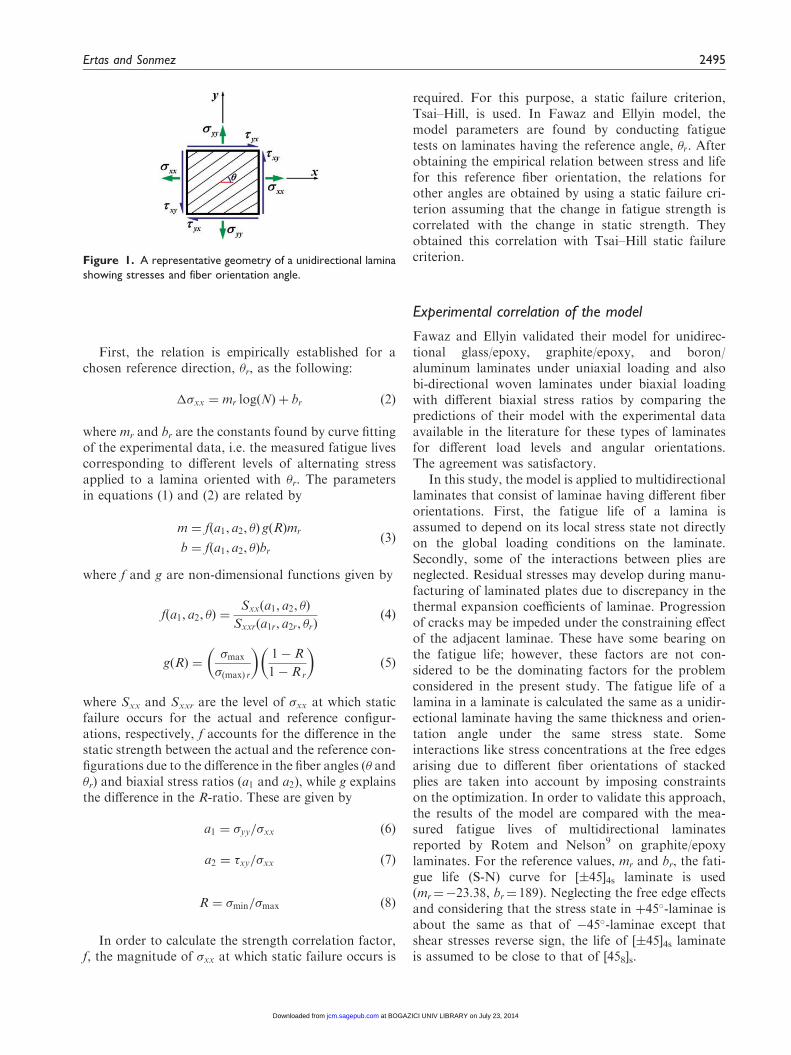
Consider a continuous fiber-reinforced lamina sub-jected to in-plane stresses, as shown in Figure 1. Fawazand Ellyin assume that a semi-log linear relationshipexists between the range of cyclic stress and the fatiguelife as the following:21
��xx ¼ m log Nð Þ þ b ð1Þ
where ��xx is the alternating normal stress along the xdirection �max � �minð Þ/2, m, and b are parametershaving values that depend on the material, the orienta-tion angle, �, and the stress state, and N is the corres-ponding number of cycles to failure.
2494 Journal of Composite Materials 48(20)
at BOGAZICI UNIV LIBRARY on July 23, 2014jcm.sagepub.comDownloaded from
First, the relation is empirically established for achosen reference direction, �r, as the following:
��xx ¼ mr log Nð Þ þ br ð2Þ
where mr and br are the constants found by curve fittingof the experimental data, i.e. the measured fatigue livescorresponding to different levels of alternating stressapplied to a lamina oriented with �r. The parametersin equations (1) and (2) are related by
m ¼ f a1, a2, �ð Þ g Rð Þmr
b ¼ f a1, a2, �ð Þbrð3Þ
where f and g are non-dimensional functions given by
f a1, a2, �ð Þ ¼Sxx a1, a2, �ð Þ
Sxxr a1r, a2r, �rð Þð4Þ
g Rð Þ ¼�max
�ðmaxÞ r
� �1� R
1� Rr
� �ð5Þ
where Sxx and Sxxr are the level of �xx at which staticfailure occurs for the actual and reference configur-ations, respectively, f accounts for the difference in thestatic strength between the actual and the reference con-figurations due to the difference in the fiber angles (� and�r) and biaxial stress ratios (a1 and a2), while g explainsthe difference in the R-ratio. These are given by
a1 ¼ �yy=�xx ð6Þ
a2 ¼ �xy=�xx ð7Þ
R ¼ �min=�max ð8Þ
In order to calculate the strength correlation factor,f, the magnitude of �xx at which static failure occurs is
required. For this purpose, a static failure criterion,Tsai–Hill, is used. In Fawaz and Ellyin model, themodel parameters are found by conducting fatiguetests on laminates having the reference angle, �r. Afterobtaining the empirical relation between stress and lifefor this reference fiber orientation, the relations forother angles are obtained by using a static failure cri-terion assuming that the change in fatigue strength iscorrelated with the change in static strength. Theyobtained this correlation with Tsai–Hill static failurecriterion.
Experimental correlation of the model
Fawaz and Ellyin validated their model for unidirec-tional glass/epoxy, graphite/epoxy, and boron/aluminum laminates under uniaxial loading and alsobi-directional woven laminates under biaxial loadingwith different biaxial stress ratios by comparing thepredictions of their model with the experimental dataavailable in the literature for these types of laminatesfor different load levels and angular orientations.The agreement was satisfactory.
In this study, the model is applied to multidirectionallaminates that consist of laminae having different fiberorientations. First, the fatigue life of a lamina isassumed to depend on its local stress state not directlyon the global loading conditions on the laminate.Secondly, some of the interactions between plies areneglected. Residual stresses may develop during manu-facturing of laminated plates due to discrepancy in thethermal expansion coefficients of laminae. Progressionof cracks may be impeded under the constraining effectof the adjacent laminae. These have some bearing onthe fatigue life; however, these factors are not con-sidered to be the dominating factors for the problemconsidered in the present study. The fatigue life of alamina in a laminate is calculated the same as a unidir-ectional laminate having the same thickness and orien-tation angle under the same stress state. Someinteractions like stress concentrations at the free edgesarising due to different fiber orientations of stackedplies are taken into account by imposing constraintson the optimization. In order to validate this approach,the results of the model are compared with the mea-sured fatigue lives of multidirectional laminatesreported by Rotem and Nelson9 on graphite/epoxylaminates. For the reference values, mr and br, the fati-gue life (S-N) curve for [�45]4s laminate is used(mr¼�23.38, br¼ 189). Neglecting the free edge effectsand considering that the stress state in þ45�-laminae isabout the same as that of �45�-laminae except thatshear stresses reverse sign, the life of [�45]4s laminateis assumed to be close to that of [458]s.
Figure 1. A representative geometry of a unidirectional lamina
showing stresses and fiber orientation angle.
Ertas and Sonmez 2495
at BOGAZICI UNIV LIBRARY on July 23, 2014jcm.sagepub.comDownloaded from

Figure 2 presents a case in which the first and lastfailure loads are different. Rotem and Nelson39 pro-vided the fatigue lives of quasi-isotropic and symmetric,[0/45/�45/90]2s, specimens subjected to different levelsof alternating stress. In order to calculate the first-plyfailure life, the stress state in each lamina is found usingclassical lamination theory; then the fatigue life of eachlamina is calculated using Fawaz and Ellyin’s model;the lowest, which is that of 90�-lamina, is taken as thefirst-ply failure life. After 90�-laminae fail, the remain-ing laminae continue to transmit the load. In order tocalculate the remaining fatigue life, a progressiveapproach is used. After the 90�-laminae fail, the loadis redistributed among the surviving laminae. For thisreason, the stress states are recalculated and the fatiguelives are reevaluated. Because, after each lamina failure,stress amplitudes change, Miner’s rule is used to deter-mine the fatigue life in the remaining laminae. Thisprocedure is repeated for several load levels and the
first and final fatigue lives versus average stress areplotted in Figure 2. For this laminate configuration,no significant difference exists between the first-plyand last-ply failure lives and the predictions arewithin the scatter of the empirical data. The reason isthat although 90�-laminae are quite weak againstnormal stresses in the x direction compared to 0�-lami-nae (74MPa versus 1630MPa strength), they are sub-jected to much lower stresses (20MPa versus 250MPa).Accordingly, 90�-laminae do not fail prematurely.
Figure 3 presents a comparison of the first-ply andlast-ply failure predictions with the experimental dataprovided by Rotem and Nelson.9 The first-ply failurepredictions turn out to be greatly conservative for thisconfiguration. Only a progressive failure approach canrepresent the actual failure behavior for such layupconfigurations. One recognizes that if the fatigue livesof the individual laminae in a laminate are close to eachother like the one shown in Figure 2, the first-ply failure
Figure 2. Comparison of the first-ply and last-ply failure predictions of Fawaz and Ellyin’s model21 with the results of Rotem and
Nelson39 on quasi-isotropic glass/epoxy laminates.
Figure 3. Comparison of the first-ply and last-ply failure predictions of Fawaz and Ellyin’s model21 with the results of Rotem and
Nelson39 on cross-ply glass/epoxy laminates.
2496 Journal of Composite Materials 48(20)
at BOGAZICI UNIV LIBRARY on July 23, 2014jcm.sagepub.comDownloaded from

approach gives acceptable predictions; but if a hugedifference exists between the lives of laminae like thecase in Figure 3, the first-ply failure approach yieldshighly conservative results. This means that it can beused in a design optimization study where layer thick-ness and orientations are optimized to maximize thefatigue strength. The layers in an optimized laminatewill then have more or less the same fatigue strength;the first and the last-failure lives will then be the same.In view of that, the first-ply failure approach is adoptedin this study, and this assumption is validated after theresults are obtained.
One should note that the model does not account forthe effects of frequency, temperature, and moisture onfatigue life. Therefore, the predictions are valid only ifthe empirical reference S-N curve, equation (2), isobtained in the same environmental conditions.
Problem statement
The problem considered in this study is to design lami-nated composites subjected to in-plane loads for max-imum fatigue life. The number of distinct laminae, n,and their thickness, to, are given. The orientation angle,�k, in each lamina is to be determined in the designprocess. Accordingly, the number of design variablesis n. The orientation angles take discrete values; inother words, they are chosen from a finite set ofangles. According to the manufacturing precision, theinterval between the consecutive angles may be 15�, 10�,5�, or even smaller.
Formulation of the objective function
Considering that after design optimization, fatiguestrengths of laminae comprising the laminate will beabout the same and thus they are expected to fail sim-ultaneously, the first-ply failure approach is adopted inthe present design optimization study rather than a pro-gressive failure approach. Then, the laminate is con-sidered to have the same fatigue life as the laminathat has the shortest fatigue life, N.
In laminate design, the number of contiguous pliesof the same orientation is limited to prevent progressionof matrix damage through the thickness and thus avoidlarge matrix cracks; the maximum thickness is experi-mentally determined and it is usually taken as four pliesfor CFRP laminates under static loading.40 Someexperimental studies41 suggest increased matrix crackgrowth for laminates with laminae containing morethan two plies. As another failure mode, edge delamin-ations tend to increase if the difference between theangles of two consecutive laminae exceeds 45�.40
These factors are taken into account in the present opti-mization procedure by imposing constraints and adding
penalty values to the objective function whenever theseconstraints are violated. Whenever a new configurationis generated by the search algorithm, these require-ments are checked; if the difference between the fiberangles of two consecutive laminae, ��, is greater 45�, apenalty value equal to ���45 is added. If the numberof plies in a lamina, nk, is larger than two, a penaltyvalue equal to 10ðni � 2Þ is added. If the differencebetween the fiber angles of consecutive laminae is lessthan 5�, the sum of the number of plies in those laminaeis also constrained not to exceed two. Considering theseconstraints, the objective function is formulated as
f ¼ � logðNÞ þ c1Xi2I
10 ni � 2ð Þ þ c2Xj2J
��j � 45� �
ð9Þ
where ni is the number of consecutive plies having thesame orientation, I is the set of laminae in which thecontiguity constraint is violated, ��j is the differencebetween the fiber angles of two consecutive laminae,J is the set of laminae in which the angle-differenceconstraint is violated, c1 and c2 are weighing factors.Because the search algorithm is constructed to minim-ize the objective function, the negative of the fatigue lifeof the laminate, N, is taken in the objective function.Besides logarithm of N is taken so that the order ofmagnitudes of the terms in the objective function areabout the same.
In order to determine N, fatigue life of each lamina iscalculated using equation (1) and the smallest of them ischosen as the fatigue life of the laminate, N.
The optimization procedure proposed in this studydoes not make use of the endurance limit of the mater-ial. A laminate configuration is considered to be morefatigue-resistant than another if the fatigue life esti-mated by the fatigue model is longer than that of theother even if the applied cyclic stress is less than theirendurance limits and actually they both have infinitefatigue life. Here we assume that the former will havea longer life in a harsher loading condition.
Optimization methodology
Optimization algorithm
In this study, a variant of SA algorithm is used.42 Thesearch algorithm is presented in Figure 4. The algo-rithm is similar to direct search simulated annealing(DSA)43 in that a set of current configurations ratherthan a single current configuration is maintained duringthe optimization process. Accordingly, unlike thestandard SA algorithm where only the neighborhoodof a single point is searched, the present algorithm
Ertas and Sonmez 2497
at BOGAZICI UNIV LIBRARY on July 23, 2014jcm.sagepub.comDownloaded from

searches the neighborhood of all the current points inthe set. At the start of the optimization process, initialconfigurations are randomly created within the designdomain by randomly selecting values for the designvariables. The number of initial configuration, M, isequal to 8(nþ 1), where n is the number of designvariables as mentioned before. The design variablesare the orientation angles of the fibers in the laminae,�i. In order to generate an initial laminate configur-ation, values among (�90, �90þ�, . . . , �2�, ��, 0,�, 2�, . . . , 90��, 90) are randomly chosen for thelamina angles, �i. Here � is the interval between con-secutive angles, which may be 1�, 5�, 10�, 15�, 30�,45�, or 90� according to the manufacturing precision.After the initial laminate configurations are randomlychosen, their objective function values are calculated.SA requires random generation of a new configurationin each iteration. For this purpose, a configuration inthe neighborhood of one of the current configurationsis randomly generated as follows: First, one of thecurrent configurations is randomly chosen. Then,
random differences are introduced to the fiber orien-tation angles.
�0k ¼ �k þ r��max ð10Þ
where �i is the fiber orientation angle in the ith layer ofthe randomly chosen current configuration; �0i is thefiber orientation angle of the ith lamina in the newlygenerated configuration; r is a randomly chosen realnumber within [�1, 1]; ��max is the maximum variationthat may be introduced to �i. �
0i is rounded to the near-
est discrete angle along which the fibers can be oriented.The lower and upper limits for �0i are �90
� and 90�,respectively. If a number greater than 90 is generatedfor �0i, 180 is subtracted from this number. If it is lessthan �90, 180 is added. Then, the structural analysis ofthe laminate is carried out using the classical laminationtheory to determine the stress state generated due to themaximum load. Since the structure is assumed to belinear, the stresses corresponding to the minimumload are obtained by reducing the calculated stressesby the minimum-to-maximum-load ratio. Using thecalculated values of the stress components, ��xx,��yy, and ��xx, the fatigue life of each lamina is esti-mated using equation (1). Then, the minimum value ischosen as the fatigue life of the laminate. Acceptabilityof a newly generated trial configuration, At, depends onthe value of its cost, ft, which is calculated by
At ¼1 if ft � fh
expðð fh � ftÞ=TkÞ if ft 4 fh
�ð11Þ
where fh is the cost (objective function value) of one ofthe high-cost current configurations; Tk is the tempera-ture parameter for the kth Markov chain. Iterationsduring which the value of the temperature (or control)parameter, Tk, is kept constant are called kth Markovchain (or inner loop). According to equation (11), everynew design having a cost lower than the cost of theworst design is accepted. But, if the cost is higher,the trial configuration may be accepted depending onthe value of At. If it is greater than a number randomlygenerated between 0 and 1, Pr, the trial configuration isaccepted, otherwise rejected. The number of iterations,L, executed in a Markow chain is calculated accordingto the formula provided by Ali et al.43:
Lk ¼ Lþ L 1� ef‘�fh� �
ð12Þ
Here
L ¼ 10n ð13Þ
where n is the number of design variables, which isequal to the number of distinct lamina angles; f‘ is
Figure 4. The main optimization procedure.
2498 Journal of Composite Materials 48(20)
at BOGAZICI UNIV LIBRARY on July 23, 2014jcm.sagepub.comDownloaded from

the value of the best current configuration, which haslowest objective function value.
The temperature parameter, T, controls the conver-gence of the optimization process just like the tempera-ture controls micro-structural changes in the physicalannealing process. At the start, the value of the tem-perature parameter is chosen to be so large that almostany arbitrary configuration is accepted. This is becausein order to prevent getting stuck into a local minimumat early stages of the optimization and search a largedesign space, the probability of acceptability must behigh. This stage resembles melting in the physicalannealing where atoms can rearrange themselvesfreely. After all the iterations in an inner loop are exe-cuted, the temperature parameter, T, is reduced, a newinner loop begins. The reduction scheme is as follows
Tk ¼ �kTk�1 ð14Þ
where Tk�1 is the temperature parameter in the (k�1)th
Markov chain and �k is temperature reduction factor.As equation (11) implies, when T is decreased, theprobability that a configuration with a higher cost isaccepted becomes lower. At low values of temperatureparameter, acceptability becomes low; thus at low tem-peratures, acceptance of worse configurations is unli-kely, just as the atoms become stable, and do nottend to change their arrangements.
In DSA, if a new configuration is accepted, itreplaces the worst configuration. The replacementscheme of DSA has one drawback that becomes espe-cially apparent with a high number of design variables.For instance, if one optimizes a laminate with 16 dis-tinct lamina angles using DSA, the number of currentconfigurations will be 8(16þ 1)¼ 136. At the initialstages of the optimization process, the current config-urations quickly gather around local minimums exceptthe worst one, which is frequently updated by higher-cost configurations at high temperatures. Because newconfigurations are generated in the neighbourhood ofthe current ones, search becomes restricted to a smallsegment of the feasible domain except for the trials inwhich the new configuration is generated around theworst current configuration, which are very infrequent.In order to remedy this, the replacement scheme ofDSA was modified. The current configurations areordered with respect to their objective function value.If a new configuration is accepted, it replaces a currentconfiguration randomly chosen among (nþ 1) worstconfigurations instead of the worst one. Thus, 7(nþ 1)of the current configurations having low cost remain inthe set unless better ones are found through iterations.The others, on the other hand, may be replaced byhigher cost configurations with a probability dependingon the temperature parameter. In this way, (nþ 1)
configurations become dispersed in the feasibledomain at high temperatures and thus a thoroughsearch of the feasible domain can be achieved. In thepresent version of the algorithm, the objective functionvalue of the best of the worst (nþ 1) current configur-ations is used for fh in equation (11).
In order to find the globally optimal design, oneshould be able to search a large solution domain. Forthis reason, instead of giving small perturbations to thecurrent configuration to obtain a new configuration inits near neighborhood, one should allow a large vari-ance in the current configurations. For this reason, themagnitude of ��max is taken as 50�. This means that theneighborhood of a current configuration where a newconfiguration is generated is initially quite large. In thisway, the solution domain can fully be searched. Thiscan also be considered as a logical consequence ofsimulating the physical annealing process, where mobil-ity of atoms is large at high temperatures, and thus theprobability that atoms may form a quite different con-figuration is high. In the present search, algorithmunlike DSA, the magnitude of ��max is not kept con-stant. ��max, thus variation in �k, is reduced as the tem-perature parameter is decreased; but the reductionscheme of the search algorithm does not directlydepend on temperature. If there is no improvementon the worst of the best 7(nþ 1) current configurationsduring a Markow chain, ��max is reduced by multiply-ing with a factor to make the searched region smallerand thus increase the likelihood of finding a betterdesign.
��0max ¼ c ��max ð15Þ
where c¼ 0.999. Reduction of the maximum variationin the optimization variables is a feature of the presentsearch algorithm that is different from DSA: Here,there is a similarity to the physical annealing process,where the mobility of atoms decreases as the tempera-ture is lowered. Reduction in the temperature should beslow enough to allow time-dependent micro-structuralchanges to occur and to reach equilibrium. In SA, non-improvement in the current set implies that furtherchanges are unlikely with the current values of ��max.For this reason, a reduction scheme different from SAor DSA algorithms is adopted for the temperature par-ameter. Instead of reducing Tk by a specific ratio, it ismade dependent on the reduction in ��max, because it isa better indication of equilibrium at a specific tempera-ture level. The temperature reduction factor, �k inequation (14), is calculated as
�k ¼�max if Lk
a=Lk 5 ��maxð Þ= ��imaxð Þ½ � þ 0:01
�min else
(ð16Þ
Ertas and Sonmez 2499
at BOGAZICI UNIV LIBRARY on July 23, 2014jcm.sagepub.comDownloaded from
where Lk is the number of trials executed in the kth
Markow chain and Lka is the number of accepted con-
figurations. Accordingly, Lka=L
k ratio is a measure ofacceptability in a Markow chain. ��max and ��imax arethe current and initial maximum variation in the laminaangles, respectively. �max and �min are taken to be0.9999 and 0.99. Through the use of this equation,the value of the temperature parameter is controlledso that acceptability of Markow chains, Lk
a=Lk,
become out equal to the ratio of the current and initialmaximum variance, ��max=��imax. When the accept-ability is higher, temperature parameter is reduced ata faster rate, �min; otherwise at a slower rate, �max. Atthe initial stages of the optimization, the right hand sideof the inequality is close to 1.0; accordingly, the tem-perature level is kept high such that the ratio of thenumber of accepted trials to the total number of trialsremains close to 1.0. When ��max approaches zero atthe end of the optimization process, temperature par-ameter also approaches zero; acceptability of a newconfiguration, At in equation (11), then comes closeto zero. Iterations are continued until the differencebetween the values of the best and the worst currentconfigurations becomes small.
Numerical results and discussions
Results were obtained for a unidirectional E-glass/epoxy fiber-reinforced material with the materialproperties given31 as E11¼ 181GPa, E22¼ 10.3GPa,G12¼ 7.17GPa, n12¼ 0.28, Xt¼�Xc¼ 1235.64MPa,Yt¼�Yc¼ 28.44MPa, and S¼ 37.95MPa. The plythickness is 0.127mm. The reference values for fatiguelife are mr¼�15.31 and br¼ 148.13 obtained for�r¼ 15�. R ratio is 0.1. The aforementioned design opti-mization algorithm was applied to laminates havingvarious lay-up configurations and subjected to differenttypes of in-plane loads.
Optimum designs obtained with unconstrainedoptimization
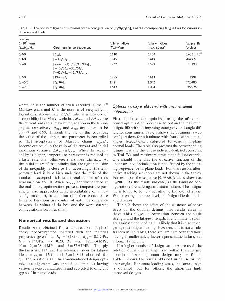
First, laminates are optimized using the aforemen-tioned optimization procedure to obtain the maximumfatigue life without imposing contiguity and angle dif-ference constraints. Table 1 shows the optimum lay-upconfigurations for a laminate with four distinct laminaangles, [�4/�4/g4/�4]s, subjected to various in-planenormal loads. The table also presents the correspondingfatigue lives and the failure indices calculated accordingto Tsai–Wu and maximum stress static failure criteria.One should note that the objective function of theunconstrained optimization is not affected by the stack-ing sequence for in-plane loads. For this reason, alter-native stacking sequences are not shown in the tables.For example, the sequence [04/90404/904]s is shown as[08/908]s. As the results indicate, all the laminate con-figurations are safe against static failure. The fatiguelife is found to be very sensitive to the level of stress.With a change in stress level, the fatigue life dramatic-ally changes.
Table 2 shows the effect of the existence of shearstress on the optimal designs. The results given inthese tables suggest a correlation between the staticstrength and the fatigue strength. If a laminate is stron-ger against static loading, it is likely that it is also stron-ger against fatigue loading. However, this is not a rule.As seen in the tables, there are laminate configurationshaving a smaller safety factor against static failure, buta longer fatigue life.
If a higher number of design variables are used, thesolution domain is enlarged and within the enlargeddomain a better optimum design may be found.Table 3 shows the results obtained using 16 distinctfiber angles. For some loading cases, the same designis obtained; but for others, the algorithm findsimproved designs.
Table 1. The optimum lay-ups of laminates with a configuration of [�4/�4/g4/�4]s and the corresponding fatigue lives for various in-
plane normal loads.
Loading
(�105 N/m)
Nxx/Nyy/Nxy Optimum lay-up sequences
Failure indices
(Tsai–Wu)
Failure indices
(max. stress)
Fatigue life
(cycles)
5/0/0 [016]s 0.010 0.100 5.633� 108
5/3/0 [�388/388]s 0.145 0.419 284,222
5/5/0 [�4/(�þ 90)4/�4/(�þ 90)4]s,
[�104/804/�304/604]s,
[�454/454/�154/754]s, . . .
0.262 0.579 11,190
5/7/0 [498/�508]s 0.355 0.663 1291
5/�5/0 [08/908]s 2.121 2.892 972,480
5/�7/0 [08/908]s 1.542 1.884 25,926
2500 Journal of Composite Materials 48(20)
at BOGAZICI UNIV LIBRARY on July 23, 2014jcm.sagepub.comDownloaded from

Table 3 also presents failure indices calculated usingTsai-Wu static failure criterion and fatigue lives of eachlamina. After the fiber orientations of the laminate areoptimized, static strengths of the laminae nearlybecome equivalent. The differences may be attributedto the discrete nature of lamina angles and thicknesses.Because fatigue life is very sensitive to stress levels, 10%difference in stress levels may result in an order of mag-nitude difference in fatigue life. For this reason, fatiguelives of laminae show much larger variance. However,in all of the optimum designs, the first ply and last plyfailure loads are the same. This justifies the use of afirst-ply-failure criterion for smooth plates in the pre-sent design optimization methodology. However, in the
optimization of notched plates, a progressive failureapproach may be a better choice.
There are also counter intuitive results. For theloading case, Nxx¼ 5� 105, Nyy¼ 2.5� 105, Nxy¼
5� 105N/m, the optimum configuration is [3814/�522]s and its fatigue life is 576,080 cycles (Table 3).When Nyy is increased to 7.5� 105N/m, the optimumconfiguration becomes [348/708] and the fatigue life ofthe optimum configuration increases to 1.729� 106
cycles (Table 2). This means that in some cases, if onecomponent of stress is increased, the algorithm mayfind a design with higher fatigue strength. The reasonfor this is that increased Nyy results in a higher level ofstress along the fiber direction in the new optimum
Table 2. The effect of shear forces on the optimum lay-ups of laminates with a configuration of [�4/�4/g4/�4] and the
corresponding fatigue lives.
Loading (�105 N/m)
Nxx/Nyy/Nxy
Optimum lay-up
sequences
Failure indices
(Tsai–Wu)
Failure indices
(max. stress)
Fatigue life
(cycles)
0/0/5 [458/�458]s 0.222 0.346 972,480
5/0/5 [314/328/�584]s 0.290 0.400 283,626
5/2.5/5 [3812/�524]s 0.318 0.504 76,212
5/5/5 [4516]s 0.040 0.199 6.700� 107
5/7.5/5 [348/708]s 0.105 0.246 1.729� 106
5/10/5 [378/808]s 0.184 0.322 84,475
5/5/2.5 [148/768]s 0.152 0.345 226,282
5/5/7.5 [�454/4512]s 0.628 0.685 1186
Table 3. The optimum lay-ups of laminates obtained using 16 distinct lamina angles and the corresponding fatigue lives for various
loadings.
Loading (�105 N/m) Nxx/Nyy/Nxy Optimum lay-up sequences Failure indices (Tsai–Wu) Fatigue life (cycles)
5/7/0 [495/�495/�503/503]s (0.356/0.356/0.352/0.352) (1296/1296/1369/1369)
5/�7/0 [07/909]s (0.346/0.289) (106,130/323,617)
5/2.5/5 [3814/�522]s (0.191/0.243) (2,001,512/576,498)
5/10/5 [367/42/808]s (0.187/0.142/0.186) (85,514/269,161/87,032)
5/5/7.5 [�452/4514]s (0.492/0.566) (17,029/5504)
Table 4. The effect of shear forces on the optimum lay-ups of laminates with a configuration of [�4/�4/g4/�4] and the corresponding
fatigue lives.
Loading (�105 N/m)
Nxx/Nyy/Nxy Optimum lay-up sequences
Failure indices
(Tsai–Wu)
Fatigue life
(cycles)
0/0/5 [�47/�45/�42/�47/�42/�45/�47/�23/22/43/46/48/43/46/48/43]s 0.265 171,738
5/2.5/5 [41/39/36/41/39/36/41/39/36/42/39/37/3/�42/�60/�55]s 0.307 118,376
5/5/2.5 [11/16/112/16/112/26/71/782/73/782/73/78]s 0.165 160,972
5/5/7.5 [�462/�59/76/47/45/42/472/42/45/47/42/45/48/43]s 0.606 1642
Ertas and Sonmez 2501
at BOGAZICI UNIV LIBRARY on July 23, 2014jcm.sagepub.comDownloaded from

configuration, but a lower stress transverse to it due toPoisson’s effect. In other words, when Nyy is increasedfrom 2.5� 105 to 7.5� 105N/m, the more damagingstress component decreases in the optimal design,while the stress components against which the laminateis much stronger increase.
If, instead of optimal laminates, quasi-isotropiclaminates having the same thickness are used underthe same conditions, most of them fail at the firstload cycle. The failure indices of the quasi-isotropiclaminates are much larger than that of the optimallaminates.
Optimum designs with contiguity and angledifference constraints
Some of the laminate designs given in Tables 1 to 3 canbe reconfigured to satisfy the constraints; for example[348/708]s can be rearranged as [342/702/342/702/342/702/342/702]s so that the laminae do not contain more thantwo plies and the angles between the neighboring lami-nae do not exceed 45�. On the other hand, for someloading cases, constraints need to be imposed.Otherwise, growth of transverse cracks and edge delam-inations, which are the factors not accounted for by thefatigue assessment model, may significantly reduce thefatigue life of the laminate. Table 4 presents the con-strained optimization results. The failure indices of theoptimum laminate designs satisfying the constraints arenot much lower than that of the designs obtained withunconstraint optimization; some of them have evenhigher values.
Conclusions
In this study, an optimization procedure, a variant ofSA, is proposed to find the globally optimum designs ofcomposite laminates subjected to given in-plane loadsfor maximum fatigue life. Fiber orientation angle ineach layer is taken as design variable. The fatigue-lifeprediction models proposed in the literature were exam-ined and compared as to their success in correlatingwith the experimental data in a wide range of loadingconditions and laminate designs. The model proposedby Fawaz and Ellyin21 accounts for the effect of fiberangle, biaxial loading, and R ratio. For this reason, thismodel is used to estimate the fatigue lives of the con-figurations generated during optimization.
The search algorithm turned out to be consistent andreliable in finding the optimum designs. The optimiza-tion process was repeated at least 10 times starting fromrandom initial configurations for each loading case. Inalmost all of these runs, the same optimum design wasfound even with a large number of optimizationvariables.
Results are also obtained by imposing contiguityconstraint, that means no lamina may contain morethan two plies, and the constraint that the differencebetween two consecutive laminae may not exceed 45�.The fatigue model does not account for these factorsaffecting fatigue life.
The fatigue strength is correlated with the staticstrength. Laminates that are stronger against staticloading are also stronger against fatigue loading.However, for a number of loading cases, some laminatedesigns were found to have longer fatigue lives in com-parison to some others; but they also have lower safetyfactors against static failure according to the chosenfailure criteria.
Fatigue life was found to be very sensitive to stresslevel. Increasing the stress level dramatically shortensthe fatigue life. Therefore, one should be more cautiousin designing structures against fatigue failure.
The first-ply and last-ply failure loads are found tobe the same for all of the optimum designs. This justi-fies the use of the first-ply failure approach in the pre-sent study.
In some loading cases, the optimal designs can becounter intuitive. Sometimes, when one component ofloading is increased, it is possible to find a laminatedesign with a longer fatigue life. Therefore, a designprocess for composite materials should not be basedon intuition or experience.
Funding
This paper is based on the work supported by TUBITAK,The Scientific and Technological Research Council ofTurkey, with code number 106M301.
Conflict of interest
None declared.
References
1. Hahn HT and Kim RY. Fatigue behavior of composite
laminate. J Compos Mater 1976; 10: 156–180.2. Adali S. Optimization of fibre reinforced composite lamin-
ates subject to fatigue loading. In: Marshall IH (ed.)Composite structures. London, UK: Elsevier Applied
Science, 1986, pp.43–55.3. Walker M. A method for optimally designing laminated
plates subject to fatigue loads for minimum weight using a
cumulative damage constraint. Compos Struct 2000; 48:213–218.
4. Harris B. Fatigue in composites: science and technology ofthe fatigue response of fibre-reinforced plastics, 2nd ed.
Cambridge, UK: Wood-head Publishing Ltd, 2008.5. Sihn S and Park JW. MAE: an integrated design tool for
failure and life prediction of composites. J Compos Mater
2008; 42: 1967–1988.6. Reifsnider KL. Fatigue of composite materials. London:
Elsevier Science Ltd, 1991.
2502 Journal of Composite Materials 48(20)
at BOGAZICI UNIV LIBRARY on July 23, 2014jcm.sagepub.comDownloaded from

7. Quaresimin M, Susmel L and Talreja R. Fatigue behav-iour and life assessment of composite laminates undermultiaxial loadings. Int J Fatigue 2010; 32: 2–16.
8. Caprino G. Predicting fatigue life of composite laminatessubjected to tension-tension fatigue. J Compos Mater2000; 34: 1334–1355.
9. Rotem A and Nelson HG. Failure of a laminated com-
posite under tension-compression fatigue loading.Compos Sci Technol 1989; 36: 45–62.
10. Wu WF, Lee LJ and Choi ST. A study of fatigue damage
and fatigue life of composite laminates. J Compos Mater1996; 30: 123–137.
11. Smith EW. Cyclic biaxial deformation and failure of a
glass fibre-reinforced composites. PhD Thesis,Cambridge University, England, 1976.
12. Sims DF and Brogdon VH. Fatigue behavior of compos-
ites under different loading modes. In: Reifsnider KL andLauraitis KN (eds) Fatigue of filamentary compositematerials, ASTM Special Technical Publication No: 636.Philadelphia: American Society for Testing and
Materials, 1977, pp.185–205.13. Rotem A. Fatigue failure of multidirectional laminate.
AIAA J 1979; 17: 271–277.
14. Rotem A and Hashin Z. Fatigue failure of angle plylaminates. AIAA J 1976; 14: 868–872.
15. Shokrieh MM and Lessard LB. Multiaxial fatigue
behaviour of unidirectional plies based on uniaxial fati-gue experiments-I. modeling. Int J Fatigue 1997; 19:201–207.
16. Bathias C. An engineering point of view about fatigue of
polymer matrix composite materials. Int J Fatigue 2006;28: 1094–1099.
17. Hashin Z. Failure criteria for unidirectional fiber com-
posites. J Appl Mech 1980; 47: 329–335.18. Kere P, Lyly M and Koski J. Using multicriterion opti-
mization for strength design of composite laminates.
Compos Struct 2003; 62: 329–333.19. Harik VM and Bogetti TA. Low cycle fatigue of compos-
ite laminates: a damage-mode-sensitive model. J Compos
Mater 2003; 37: 597–610.20. Fawaz Z and Ellyin F. A new methodology for the pre-
diction of fatigue failure in multidirectional fiber-rein-forced laminates. Compos Sci Technol 1995; 53: 47–55.
21. Fawaz Z and Ellyin F. Fatigue failure model for fiber-reinforced materials under general loading conditions.J Compos Mater 1994; 28: 1432–1451.
22. Nijssen RPL. Fatigue life prediction and strength degrad-ation of wind turbine rotor blade composites. Delft,Netherlands: Knowledge centre wind turbine materials
and constructions, 2006.23. Noda J, Nakada M and Miyano Y. Fatigue life predic-
tion under variable cyclic loading based on statisticallinear cumulative damage rule for CFRP laminates.
J Reinf Plast Compos 2007; 26: 665–680.24. Shokrieh MM and Lessard LB. Progressive fatigue
damage modeling of composite materials, part I: model-
ing. J Compos Mater 2000; 34: 1056–1080.25. Shokrieh MM and Lessard LB. Progressive fatigue
damage modeling of composite materials, part II:
material characterization and model verification. JCompos Mater 2000; 34: 1081–1115.
26. Liu Y and Mahadevan S. Probabilistic fatigue life predic-
tion of multidirectional composite laminates. ComposStruct 2008; 69: 11–19.
27. Wu FQ and Yao WX. A model of the fatigue life distri-bution of composite laminates based on their static
strength distribution. Chin J Aeronaut 2008; 21: 241–246.28. Kassapoglou C. Fatigue life prediction of composite
structures under constant amplitude loading. J Compos
Mater 2007; 41: 2737–2754.29. Ellyin F and El-Kadi H. A fatigue failure criterion for
fiber reinforced composite laminae. Compos Struct 1990;
15: 61–74.30. Epaarachchi JA and Clausen PD. An empirical model for
fatigue behavior prediction of glass fibre-reinforced plas-
tic composites for various stress ratios and test frequen-cies. Compos A Appl Sci Manuf 2003; 34: 313–326.
31. Hashin Z and Rotem A. A fatigue failure criterion forfiber reinforced materials. J Compos Mater 1973; 7:
448–464.32. Mouritz AP. A simple fatigue life model for three-
dimensional fiber-polymer composites. J Compos Mater
2006; 40: 455–469.33. Mao H and Mahadevan S. Fatigue damage
modeling of composite materials. Compos Struct 2002;
58: 405–410.34. Nyman T. Composite fatigue design methodology: a sim-
plified approach. Compos Struct 1996; 35: 183–194.35. Hwang W and Han KS. Fatigue of composites-fatigue
modulus concept and life prediction. J Compos Mater1986; 20: 154–165.
36. Vassilopoulos AP and Bedi R. Adaptive neuro-fuzzy
inference system in modelling fatigue life of multidirec-tional composite laminates. Comput Mater Sci 2008; 43:1086–1093.
37. Al-Assadi M, El Kadi H and Deiab IB. Predictingthe fatigue life of different composite materialsusing artificial neural networks. Appl Compos Mater
2010; 17: 1–14.38. Huang ZM. Micromechanical life prediction for compos-
ite laminates. Mech Mater 2001; 33: 185–199.39. Rotem A and Nelson HG. Residual strength of compos-
ite laminates subjected to tensile-compressive fatigueloading. J Compos Technol Res 1990; 12: 76–84.
40. Irisarri FX, Bassir DH, Carrere N, et al. Multiobjective
stacking sequence optimization for laminated compositestructures. Compos Sci Technol 2009; 69: 983–990.
41. Xu L-Y. Influence of stacking sequence on the transverse
matrix cracking in continuous fiber crossply laminates.J Compos Mater 1995; 29: 1337–1358.
42. Akbulut M and Sonmez FO. Design optimization oflaminated composites using a new variant of simulated
annealing. Comput Struct 2011; 89: 1712–1724.43. Ali MM, Torn A and Viitanen S. A direct search variant
of the simulated annealing algorithm for optimization
involving continuous variables. Comput Oper Res 2002;29: 87–102.
Ertas and Sonmez 2503
at BOGAZICI UNIV LIBRARY on July 23, 2014jcm.sagepub.comDownloaded from