Embed Size (px)
Citation preview

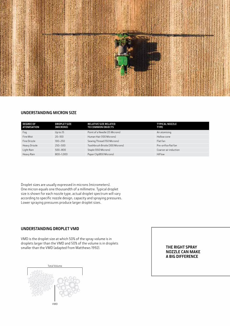
JOHN DEERE SPRAY NOZZLESTHE KEY TO SUCCESSFUL SPRAYING
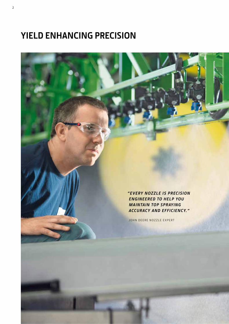
YIELD ENHANCING PRECISION
“ E VERY NOZ Z LE I S P R EC I SION ENGINEER ED TO HELP YO U MAINTAIN TOP SP R AYING ACC UR AC Y AND EFFIC IENC Y. ”
J O H N D E E R E N O Z Z L E E X P E R T
2

CONTENTSWHAT’S NEW? 05
3D Nozzle �����������������������������������������������������������������05
Low-Drift Max ����������������������������������������������������������05
Low-Drift Twin ����������������������������������������������������������05
Ultra Low-Drift Max ��������������������������������������������������05
NOZZLE BASICS 06
What You Need to Know ��������������������������������������������06
John Deere Label Information ������������������������������������07
Spray Nozzles Don’t Last Forever �������������������������������08
Spray Nozzles Tools ���������������������������������������������������09
Making the Right Choices ������������������������������������������10
SPRAY GUIDE 14
John Deere Spray Nozzle Selection Guide �������������������14
A John Deere Nozzle for every Application �����������������16
Spray Nozzle Selection Chart �������������������������������������18
BROADCAST NOZZLES 20
3D 100° �������������������������������������������������������������������22
Low-Drift Max (LDM) 120° ���������������������������������������24
Low-Drift Twin (LDT) 110° ����������������������������������������26
Ultra Low-Drift Max (ULDM) 130° �����������������������������28
Ultra Low-Drift (ULD) 120° ���������������������������������������30
GuardianAIR Twin (GAT) 110° ������������������������������������32
Low-Drift Air (LDA) 110° �������������������������������������������34
Extended Range (ER) 110° ����������������������������������������36
Extended Range Ceramic (ERC) 110° �������������������������38
Guardian (LDX) 120° �������������������������������������������������40
Straight Stream Ceramic (STC) �����������������������������������42
High Flow (HF) 140° �������������������������������������������������44
Broadcast Nozzles Index ��������������������������������������������46
SPRAY TIPS AND SPECIALTY NOZZLES 50
Boomless Nozzles (XT) ��������������������������������������������� 52
Spray Tip Only Index ������������������������������������������������� 54
John Deere offers spray nozzles for a variety of pressure ranges, flow rates and spray patterns to fit any spray application and your individual needs. Select the optimum nozzle to enhance your yield and boost your business. Discover our complete nozzle range in this guide!
3
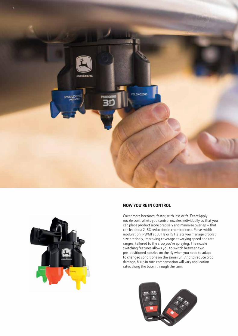
NOW YOU’RE IN CONTROL
Cover more hectares, faster, with less drift. ExactApply nozzle control lets you control nozzles individually so that you can place product more precisely and minimise overlap – that can lead to a 2–5% reduction in chemical cost. Pulse-width modulation (PWM) at 30 Hz or 15 Hz lets you manage droplet size precisely, improving coverage at varying speed and rate ranges, tailored to the crop you’re spraying. The nozzle switching features allows you to switch between two pre-positioned nozzles on the fly when you need to adapt to changed conditions on the same run. And to reduce crop damage, built-in turn compensation will vary application rates along the boom through the turn.
4

3D NOZZLE
International field trials prove it: the new 3D model reduces drift while maintaining full efficacy and coverage. Experience drift potential reduction of up to 50–75% compared to conventional flat fan nozzles.
LOW-DRIFT MAX
This nozzle is ideal for pre and post emergence applications, where drift reduction is paramount. ExactApply, Pulse Width Modulation compatibility guarantees good spray overlap even at low flow.
LOW-DRIFT TWIN
Featuring forward (30°) and rear facing (30°) fan inclines, this nozzle ensures superior coverage on the front and back of application targets and is compatible with ExactApply and Pulse Width Modulation.
ULTRA LOW-DRIFT MAX
Compared to flat fan nozzles, it features an impressive 95% reduction in drift, with a 130° wide spray angle for effective pattern overlap even at low boom heights.
Here is some of the very latest in nozzle technology available to you from John Deere.
WHAT’S NEW?
5
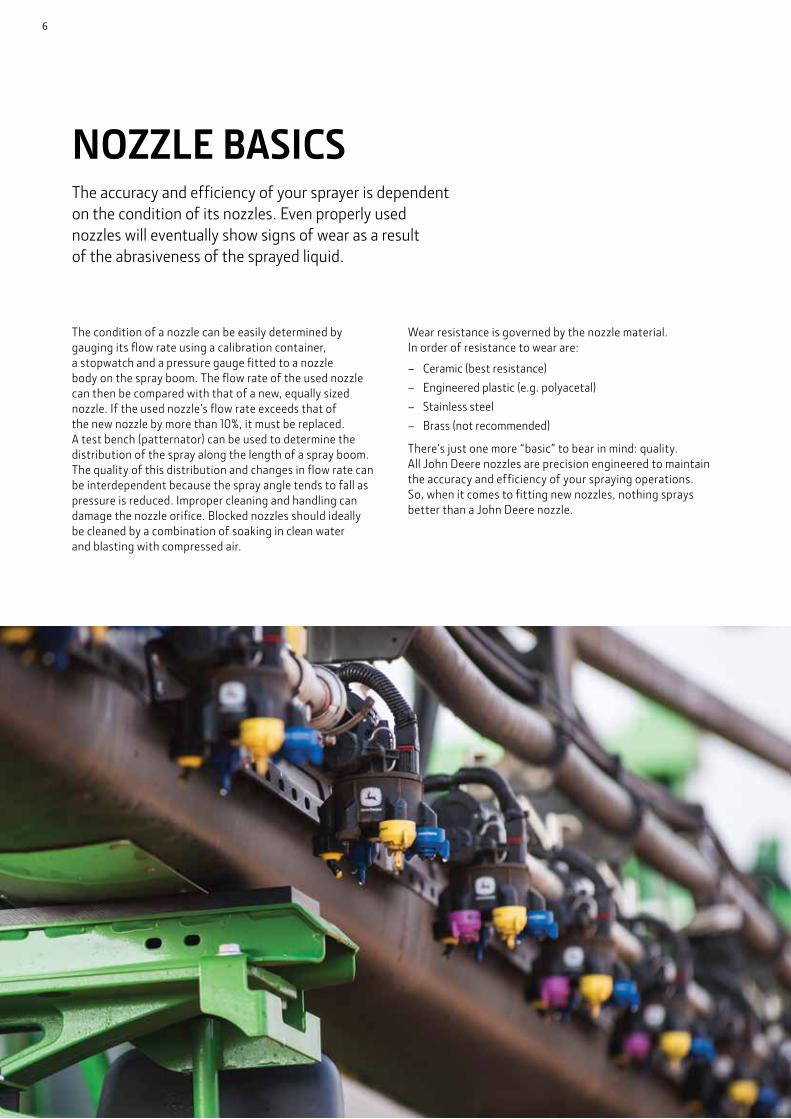
The accuracy and efficiency of your sprayer is dependent on the condition of its nozzles. Even properly used nozzles will eventually show signs of wear as a result of the abrasiveness of the sprayed liquid.
NOZZLE BASICS
The condition of a nozzle can be easily determined by gauging its flow rate using a calibration container, a stopwatch and a pressure gauge fitted to a nozzle body on the spray boom. The flow rate of the used nozzle can then be compared with that of a new, equally sized nozzle. If the used nozzle’s flow rate exceeds that of the new nozzle by more than 10%, it must be replaced. A test bench (patternator) can be used to determine the distribution of the spray along the length of a spray boom. The quality of this distribution and changes in flow rate can be interdependent because the spray angle tends to fall as pressure is reduced. Improper cleaning and handling can damage the nozzle orifice. Blocked nozzles should ideally be cleaned by a combination of soaking in clean water and blasting with compressed air.
Wear resistance is governed by the nozzle material. In order of resistance to wear are:
– Ceramic (best resistance) – Engineered plastic (e.g. polyacetal) – Stainless steel – Brass (not recommended)
There’s just one more “basic” to bear in mind: quality. All John Deere nozzles are precision engineered to maintain the accuracy and efficiency of your spraying operations. So, when it comes to fitting new nozzles, nothing sprays better than a John Deere nozzle.
6

Manufactured for / Fabriqué pour : Deere & Company, One John Deere Place, Moline, Illinois 61265
Ultra Low DriftBUSE À FAIBLE DISPERSION ULTRA1.2 L /min @ 3 BAR 0.3 US gpm @ 40 psi
PSULDQ200310GB Made in United Kingdom 20071018DY2
JOHN DEERE LABEL INFORMATION
ZONE 1 BASIC PRODUCT INFORMATION
Product name Reference flow rate and pressure Spray pattern
angle quantity, Part number, date, traceability and other codes
Tapered Fan
Even Fan
Hollow Cone
Stream
ZONE 5 STANDARD DROPLET SIZE CLASSES AT 3 BAR REFERENCE PRESSURE
Icons representing relevant droplet size (“Spray Quality”) categories of Extremely Fine, Very Fine, Fine, Medium, Coarse, Very Coarse, Extremely Coarse and Ultra Course
ZONE 6 MORE DETAILS
Web site for details and training
Liquid fertiliser
Herbicides
Plant growth
Regulators
Fungicides
Insecticides
Desiccants
ZONE 4A PRODUCT FEATURE
Twin Spray patterns
ZONE 4B PRODUCT FEATURES
Air-inducted sprays
Symbols used may vary depending on spray nozzle types.
ZONE 2 PATTERN
INDICATORS ZONE 3 USE INDICATORS
7
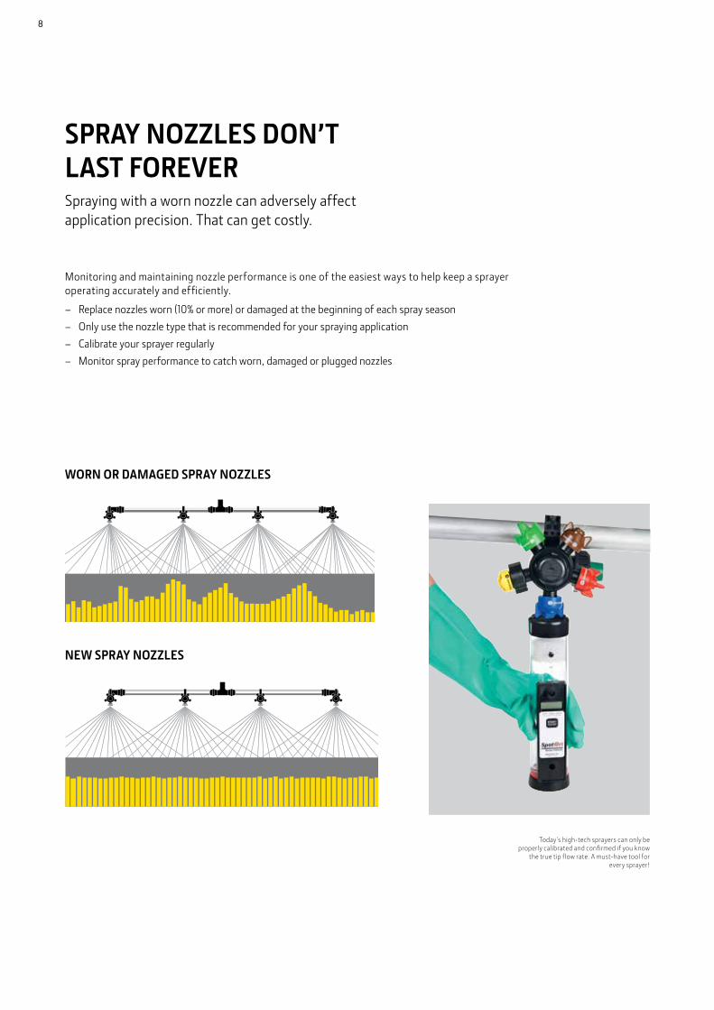
SPRAY NOZZLES DON’T LAST FOREVER
NEW SPRAY NOZZLES
WORN OR DAMAGED SPRAY NOZZLES
Spraying with a worn nozzle can adversely affect application precision. That can get costly.
Today’s high-tech sprayers can only be properly calibrated and confirmed if you know
the true tip flow rate. A must-have tool for every sprayer!
Monitoring and maintaining nozzle performance is one of the easiest ways to help keep a sprayer operating accurately and efficiently.
– Replace nozzles worn (10% or more) or damaged at the beginning of each spray season – Only use the nozzle type that is recommended for your spraying application – Calibrate your sprayer regularly – Monitor spray performance to catch worn, damaged or plugged nozzles
8

9
SPRAY NOZZLE TOOLS
SPRAY NOZZLE CALIBRATORS
These SpotOn Sprayer Calibrators quickly identify worn spray nozzle tips and accurately measure true tip flow rate. All in a simple and fast process with readings in 10 seconds or less per tip. Industry guidelines recommend spray tip replacement once flow rate exceeds that of a new tip by 10%.
PM23890
Best for flow rates below 3.8 l/min, including spray tips for herbicide and insecticide applications.
SPRAYER TIP TOOL KIT | PM28170
All the SpotOn tools a sprayer operator needs for finding worn or plugged nozzles, verifying application rate, clean plugged tips and strainers and calibrate your sprayer, all in one compact carry case.
– Spray nozzle calibrator – Gloves and goggles – Air blast tip cleaner
– Durable carry case – Tip multi-tool – Sprayer output calculator
SPOTON PAPER | PM32920
SpotOn Paper allows for quick and easy spray visualisation of:
– Spray coverage – Droplet size and uniformity – Off target application
SPRAY TIP CALIBRATION GAUGE | PMTESTKIT
The Spray Tip Calibration Pressure Gauge is attached to a cap and bayonet to test pressure at the nozzle.
THERMAL INVERSION TESTER | PM35010
The thermal inversion tester detects low level thermal inversions and air temperature at boom height as required for pesticide/herbicide applications.
SPRAY NOZZLE INSTALLATION TOOL | PS30000310
The nozzle installation tool is easy to use and light weight. It makes removing and installing nozzles faster leading to less operator fatigue.
9

MAKING THE RIGHT CHOICESSelecting the correct spray nozzle for the job at hand is essential. We have spray nozzles available for a wide range of pressures, flow rates and spray patterns.
FIRST...
First, read the product label thoroughly and look for information on droplet size, application rate, spray quality and environmental restrictions.
10

THEN…
– Check your sprayer speed – Find the proper application rate – Determine the required flow rate (LPM) or use
the application rate (L/ha) chart for the nozzle – Select the pattern type – Select nozzle size and pressure that provides
the desired flow rate and application rate – Check spray quality tables: do nozzle and
pressure create the right droplet spectrum?
1) SPRAYING TECHNIQUE
Broadcast spraying is when the entire field is to be treated. The width that each nozzle sprays, adjusted for spray overlap, is the distance between nozzles on the spray boom. Band spraying is when planted rows or unplanted gaps are treated. The width that each nozzle sprays is the width of the treated band.
2) SPRAYER SPEED
Forward speed of the spraying machine should be measured accurately. Radar or ultrasound speed sensors should be calibrated after installation or servicing. Wheel-driven speedometers should be calibrated whenever the driving surface changes, such as after cultivation. Speed can be determined if it is known how long it takes to drive a measured distance:
Improved vehicle design means that speeds up to 30 km/h are now possible. Higher speeds (15–30 km/h) improve work rates and timeliness; lower speeds (10–15 km/h) give improved canopy penetration and make spray drift control simpler.
3) APPLICATION RATE
Read the product label closely to determine an appropriate spray application rate. If a range of acceptable application rates is listed, choose a rate that best matches your situation.
4) CORRECTION FOR SPECIFIC GRAVITY OF SPRAYED LIQUID
Application rates shown in the nozzle charts in this guide are based on tests with plain water. Calculating a Correction Factor allows you to use the tables to select a nozzle for liquids that have a different specific gravity (S.G.) to water (e.g. liquid fertiliser):
Use the Correction Factor to calculate a Reference Application Rate. Look up the Reference Application Rate in the chart and the nozzle and pressure selected will apply the Target Application Rate of the higher S.G. liquid.
5) FLOW RATE
Determine the exact flow required from each nozzle by calculating:
6) NOZZLE SPACING
If your nozzle spacing differs from the spacing used in the spray nozzle application rate tables, multiply the tabulated L/HA by the conversion factor to find your actual application rate.
Example: if your nozzle spacing is 90cm, your application rate will be 0.56 times what is shown in the tables for nozzles spaced 50cm.
To calculate a conversion factor for spacing not listed, use the following formula:
‘W’ is a different measurement depending on the type of application as follows:
– Nozzle spacing (m) for broadcast spraying – Spray width (m) for single-nozzle band spraying or
boomless spraying – Row spacing (m) divided by the number of nozzles per row
for directed sprayingOr you can read the application tables throughout this guide.
SPEED IN KM/H =DISTANCE (M) X 3.6
TIME (SECONDS)
LPM =L/HA X KM/H X W
600
REFERENCE APPLICATION RATE L/HA =
TARGET APPLICATION RATE IN L/HA
CORRECTION FACTOR
CORRECTION FACTOR =1
S.G.
METRIC CONVERSION FACTOR =NOZZLE SPACING IN TABLE (CM)
YOUR NOZZLE SPACING (CM)
11

7) SPRAY FPATTERN TYPE
Flat Fan pattern
Available as a tapered spray for boom applications or an even spray for single nozzle applications. Even spray nozzles produce a narrow pattern, where spray is evenly deposited across the spray’s width. Tapered nozzles produce an elliptical spray pattern where more of the spray is deposited immediately under the tip. By overlapping tapered sprays, an even distribution across the entire boom can be obtained.
Deflect pattern
Also known as anvil or flood nozzles, deflect nozzles produce a wide-angled flat pattern when operated at low pressures (1–3 bar), These nozzles generally produce a medium to coarse, even spray.
Cone pattern
These nozzles produce either a solid circular (full cone nozzles) or a hollow circular footprint (hollow cone nozzles). Full cones are ideal for spot spraying, whereas hollow cones are used on air-assisted sprayers and directed sprays.
Other patterns
Speciality sprays call for specialty patterns, such as off-centre or streaming sprays. An off-centre pattern is used to extend spray patterns past the boom structure and streaming patterns are commonly used for fertilizer applications.
Technology – Standard or Air Induction
Along with the spray pattern, it’s important to consider the engineering behind each droplet. Standard droplets produce the traditional solid droplet. Air-induction technology creates air-filled droplets, which increase droplet retention and reduce the number of small droplets prone to drift.
Even Tapered
Anvil/Flood
Full Cone Hollow Cone
Off-Centre Streaming
Standard Droplet Air-Induction
12

8) NOZZLE SIZE AND PRESSURE
Use the flow rate tables provided throughout this guide to select the nozzle and pressure that provides the flow needed for the nozzle application.
9) SPRAY QUALITY
An important performance characteristic of spray nozzles is both the droplet size and how the droplet size varies with spraying pressure.
Fine sprays provide enhanced retention for directed spraying on the target including:
– Foliar-acting weed control – Contact-acting fungicides
and insecticides
Medium sprays are the most widely used spray type.
– Used by default by most applicators when spray quality is not defined by the label
– Systemic-acting fungicides, insecticides and herbicides
Coarse sprays are used where drift reduction is important and can give you good results especially on larger targets and with higher water volume.
– Used with systemic and soil acting fungicides, herbicides and insecticides
The droplet size classification above uses eight categories, six of which are common for agriculture and horticulture: Very Fine, Fine, Medium, Coarse, Very Coarse and Extremely Coarse. Most agrochemical applications recommend a fine, medium, or coarse spray.
* Always read the pesticide label to determine which spray quality is required.** Estimated from sample reference graph in ASABE/ANSI/ASAE Standard S572.1.
SPRAY QUALITY* SIZE OF DROPLETS VMD RANGE (MICRONS**)
COLOUR CODE RETENTION ON SMALL OR HARD TO WET TARGETS
DRIFT POTENTIAL
Extremely Fine Small <60 Purple Excellent High
Very Fine 61–105 Red Excellent
Fine 106–235 Orange Very Good
Medium 236–340 Yellow Good
Coarse 341–403 Blue Moderate
Very Coarse 404–502 Green Poor
Extremely Coarse 503–665 White Very Poor
Ultra Coarse Large >665 Black Very Poor Low
13
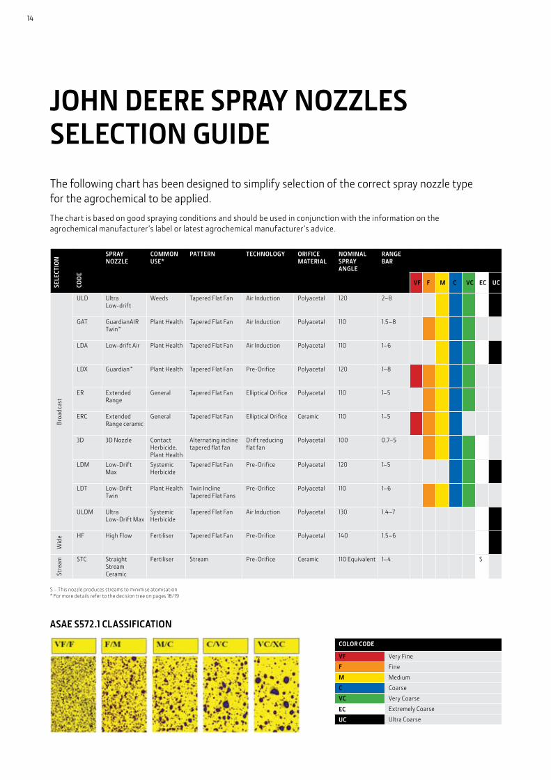
JOHN DEERE SPRAY NOZZLES SELECTION GUIDEThe following chart has been designed to simplify selection of the correct spray nozzle type for the agrochemical to be applied.The chart is based on good spraying conditions and should be used in conjunction with the information on the agrochemical manufacturer’s label or latest agrochemical manufacturer’s advice.
COLOR CODE
VF Very Fine
F Fine
M Medium
C Coarse
VC Very Coarse
EC Extremely Coarse
UC Ultra Coarse
SELE
CTIO
N
COD
E
SPRAY NOZZLE
COMMON USE*
PATTERN TECHNOLOGY ORIFICE MATERIAL
NOMINAL SPRAY ANGLE
RANGE BAR
VF F M C VC EC UC
Broa
dcas
t
ULD Ultra Low-drift
Weeds Tapered Flat Fan Air Induction Polyacetal 120 2–8
GAT GuardianAIR Twin™
Plant Health Tapered Flat Fan Air Induction Polyacetal 110 1.5–8
LDA Low-drift Air Plant Health Tapered Flat Fan Air Induction Polyacetal 110 1–6
LDX Guardian™ Plant Health Tapered Flat Fan Pre-Orifice Polyacetal 120 1–8
ER Extended Range
General Tapered Flat Fan Elliptical Orifice Polyacetal 110 1–5
ERC Extended Range ceramic
General Tapered Flat Fan Elliptical Orifice Ceramic 110 1–5
3D 3D Nozzle Contact Herbicide, Plant Health
Alternating incline tapered flat fan
Drift reducing flat fan
Polyacetal 100 0.7–5
LDM Low-Drift Max
Systemic Herbicide
Tapered Flat Fan Pre-Orifice Polyacetal 120 1–5
LDT Low-Drift Twin
Plant Health Twin Incline Tapered Flat Fans
Pre-Orifice Polyacetal 110 1–6
ULDM Ultra Low-Drift Max
Systemic Herbicide
Tapered Flat Fan Air Induction Polyacetal 130 1.4–7
Wid
e
HF High Flow Fertiliser Tapered Flat Fan Pre-Orifice Polyacetal 140 1.5–6
Stre
am
STC Straight Stream Ceramic
Fertiliser Stream Pre-Orifice Ceramic 110 Equivalent 1–4 S
S – This nozzle produces streams to minimise atomisation* For more details refer to the decision tree on pages 18/19
ASAE S572.1 CLASSIFICATION
14
DEGREE OF ATOMISATION
DROPLET SIZE (MICRONS)
RELATIVE SIZE RELATED TO COMMON OBJECTS
TYPICAL NOZZLE TYPE
Fog Up to 25 Point of a Needle (25 Microns) Air atomising
Fine Mist 20–100 Human Hair (100 Microns) Hollow cone
Fine Drizzle 100–250 Sewing Thread (150 Microns) Flat fan
Heavy Drizzle 250–500 Toothbrush Bristle (300 Microns) Pre-orifice flat fan
Light Rain 500–800 Staple (550 Microns) Coarser air induction
Heavy Rain 800–1,000 Paper Clip(850 Microns) HiFlow
UNDERSTANDING MICRON SIZE
UNDERSTANDING DROPLET VMD
VMD is the droplet size at which 50% of the spray volume is in droplets larger than the VMD and 50% of the volume is in droplets smaller than the VMD (adapted from Matthews 1992).
Droplet sizes are usually expressed in microns (micrometers). One micron equals one thousandth of a millimetre. Typical droplet size is shown for each nozzle type, actual droplet spectrum will vary according to specific nozzle design, capacity and spraying pressures. Lower spraying pressures produce larger droplet sizes.
THE RIGHT SPRAY NOZZLE CAN MAKE A BIG DIFFERENCE
VMD
Total Volume
15

A JOHN DEERE NOZZLE FOR EVERY APPLICATIONThroughout pre or post-emerge phases, our high-quality focus nozzles will deliver exactly the volumes and patterns you need for healthy crop growth. Choose the performance characteristics that suit you best.
Ideal for post-emerge application of systemic herbicide where drift reduction is paramount.
– Air-induction technology creates air-filled droplets to significantly reduce drift potential
– 130°spray angle for low boom heights and to prevent pattern collapse when using drift reducing adjuvants
Ideal for pre- and post-emerge product applications where drift reduction is paramount.
– 60°thick pattern for superior coverage
– Dual pre-orifice nozzle designed to reduce drift
– 120° spray angle for good pattern overlap and prevents pattern collapse at low percentage flow.
Ideal for pre-emerge application of systemic herbicides
– Venturi technology to greatly reduce drift
– Large air-filled droplets and unique thick pattern helps maintain spray coverage
Drift Reducing, Air Induction Drift Reducing, Air Induction Drift Reducing
Applications:
– Pre- and Post-Emerge – Systemic Herbicides
Applications:
– Pre- and Post-Emerge – Systemic Herbicides
ULTRA LOW-DRIFT MAX ULTRA LOW-DRIFT LOW-DRIFT MAX
Applications:
– Post-Emerge Systemic Herbicides
16
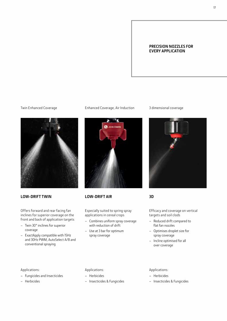
Offers forward and rear facing fan inclines for superior coverage on the front and back of application targets
– Twin 30° inclines for superior coverage
– ExactApply compatible with 15Hz and 30Hz PWM, AutoSelect A/B and conventional spraying
Especially suited to spring spray applications in cereal crops
– Combines uniform spray coverage with reduction of drift
– Use at 3 bar for optimum spray coverage
Efficacy and coverage on vertical targets and soil clods
– Reduced drift compared to flat fan nozzles
– Optimises droplet size for spray coverage
– Incline optimised for all over coverage
Twin Enhanced Coverage Enhanced Coverage, Air Induction 3 dimensional coverage
Applications:
– Fungicides and Insecticides – Herbicides
Applications:
– Herbicides – Insecticides & Fungicides
Applications:
– Herbicides – Insecticides & Fungicides
LOW-DRIFT TWIN LOW-DRIFT AIR 3D
PRECISION NOZZLES FOR EVERY APPLICATION
17

No
No
No
No
No
Yes
Yes
Yes
Yes
SPRAY NOZZLES SELECTION CHART
WHAT ARE YOU SPRAYING?
WHEN ARE YOU SPRAYING? ARE YOU USING EXACTAPPLY™ PWM SYSTEM?
Ultra Low-driftUltra Low-drift Max Low-Drift Max
No
Yes
Yes
Herbicides Weed Control
Plant growth regulators
Fungicides
Pre-Emerge
Post-Emerge
Post-Emerge
Post-Emerge
Insecticides
Desiccants
Post-Emerge
Pre-Harvest
Spray quality will vary with pressure. When using PWM system, pick a pressure that provides the right droplet spectrum for contact/system or drift control/coverage. Always follow manufacturer’s product label for recommended application rates when selecting the proper size nozzle.
18

Systemic
Systemic
Systemic
Ultra Low-Drift
Low-Drift Max
Low-Drift Max
Ultra Low-Drift
Low-Drift Twin or 3D*
Low-Drift Twin or 3D*
Low-Drift Twin or 3D*
Low-Drift Twin or 3D*
Low-Drift Max
Low-Drift Max
Low-Drift Max
Low-Drift Max
Low-Drift Max
Low-Drift Max
Low-Drift Max
Low-Drift Twin or 3D*
Low-Drift Twin or 3D*
Low-Drift Twin or 3D*
Low-Drift Twin or 3D*
Low-Drift Twin or 3D*
Low-Drift Twin or 3D*
Low-Drift Twin or 3D*
Contact
Contact
Contact
*When using the 3D and PWM at less than 30 Hz you must install the nozzles facing the same direction.
IS YOUR CHEMICAL CONTACT OR SYSTEMIC?
PRIMARY CONCERN: DRIFT PRIMARY CONCERN: COVERAGE
Low-drift Twin 3D Nozzle
Low-Drift Twin or 3D*
Low-Drift Twin or 3D*
Low-Drift Twin or 3D*
Low-Drift Twin or 3D*
Low-Drift Twin or 3D*
Low-Drift Max or Ultra Low-Drift Max
Low-Drift Max
Ultra Low-Drift Max or Ultra Low-Drift
Low-Drift Max
Low-Drift Max
Systemic
Contact
19
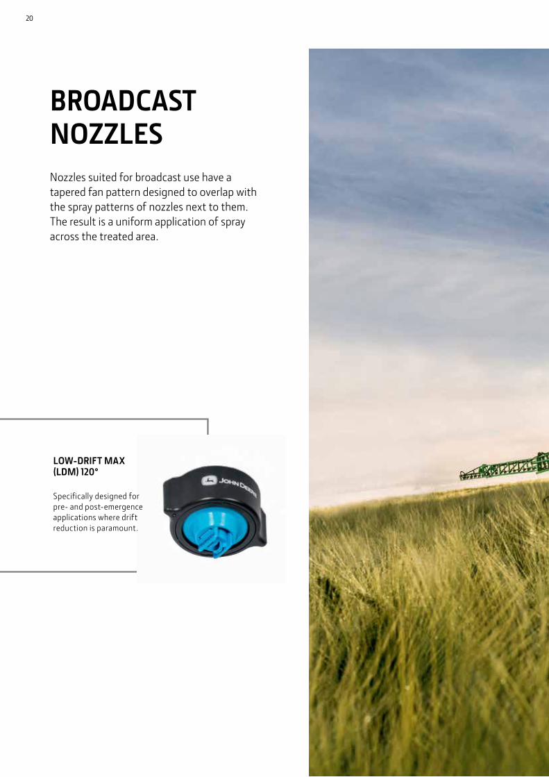
LOW-DRIFT MAX (LDM) 120°
Specifically designed for pre- and post-emergence applications where drift reduction is paramount.
BROADCAST NOZZLESNozzles suited for broadcast use have a tapered fan pattern designed to overlap with the spray patterns of nozzles next to them. The result is a uniform application of spray across the treated area.
20

21
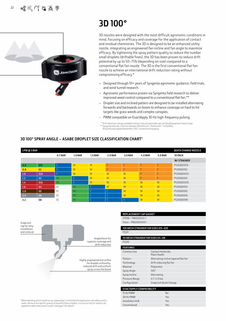
3D 100°3D nozzles were designed with the most difficult agronomic conditions in mind, focusing on efficacy and coverage for the application of contact and residual chemistries. The 3D is designed to be an enhanced utility nozzle, integrating an engineered fan incline and fan angle to maximize efficacy. By tightening the spray pattern quality to reduce the number small droplets (driftable fines), the 3D has been proven to reduce drift potential by up to 50–75% (depending on size) compared to a conventional flat fan nozzle. The 3D is the first conventional flat fan nozzle to achieve an international drift reduction rating without compromising efficacy.*
– Designed through 10+ years of Syngenta agronomic guidance, field trials, and wind tunnel research.
– Agronomic performance proven via Syngenta field research to deliver improved weed control compared to a conventional flat fan.**
– Droplet size and inclined pattern are designed to be installed alternating forwards and backwards on boom to enhance coverage on hard to hit targets like grass weeds and complex canopies.
– PWM compatible on ExactApply 30 Hz high-frequency pulsing
* Drift reduction ratings available at https://secure. pesticides. gov. uk/SprayEquipment/Search. aspx ** Syngenta UK trials. 0.6 l/ha Liberator (diflufenican + flufenacet) + 4l/ha Defy
(Prosulfacarb) applied November 2015. Conventional spraying
LPM @ 3 BAR QUICK CHANGE NOZZLE
0.7 BAR 1.0 BAR 1.5 BAR 2.0 BAR 3.0 BAR 4.0 BAR 5.0 BAR 10 PACK
W/ STRAINER
0.6 015 C M M F F F F PS3DQ00015
0.8 02 C M M F F F F PS3DQ0002
1.0 025 C M M M M F F PS3DQ00025
1.2 03 VC C M M M F F PS3DQ0003
1.4 035 VC C M M M M M PS3DQ00035
1.6 04 EC VC C M M M M PS3DQ0004
2.0 05 EC VC C C M M M PS3DQ0005
2.4 06 EC VC C C M M M PS3DQ0006
3.2 08 EC VC C C C M M PS3DQ0008
3D 100° SPRAY ANGLE – ASABE DROPLET SIZE CLASSIFICATION CHART†
REPLACEMENT CAP GASKETEPDM – PM200040-1Viton – PM200040V1
FEATURESCommon Use Contact Herbicide,
Plant HealthPattern Alternating incline tapered flat fanTechnology Drift reducing flat fanMaterial PolyacetalSpray Angle 100°Spray Incline AlternatingPressure Range 0.7–5.0 barConfiguration SnapLock Quick Change
EXACTAPPLY COMPATIBILITY15 Hz PWM No30 Hz PWM YesAutoSelect A/B YesConventional Yes
100 MESH STRAINER FOR SIZES 015–035 PS311
50 MESH STRAINER FOR SIZES 04–08PS310
Highly engineered exit orifice for droplet uniformity,
reduced drift and uniform spray scross the boom
Angled bore for superior coverage and
drift reduction
SnapLock cap for easy installation and removal
† When deciding which nozzle to use, please bear in mind that the application rate tables are for water. Because the specific gravity of liquid fertiliser is higher, a correction factor needs to be applied to select the correct nozzle. See page 11 for details.
22
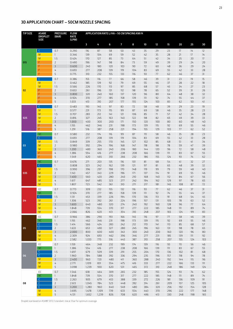
3D APPLICATION CHART – 50CM NOZZLE SPACING
Droplet size based on ASABE S572.1 standard. Use at 3 bar for optimum coverage.
TIP SIZE ASABE DROPLET SIZE
PRESSURE (BAR)
FLOW RATE (LPM)
APPLICATION RATE L/HA – 50 CM SPACING KM/H
3 4 6 7 8 10 12 15 20 25 30
015
C 0.7 0.290 116 87 58 50 43 35 29 23 17 14 12M 1 0.346 139 104 69 59 52 42 35 28 21 17 14M 1.5 0.424 170 127 85 73 64 51 42 34 25 20 17F 2 0.490 196 147 98 84 73 59 49 39 29 24 20F 3 0.600 240 180 120 103 90 72 60 48 36 29 24F 4 0.693 277 208 139 119 104 83 69 55 42 33 28F 5 0.775 310 232 155 133 116 93 77 62 46 37 31
02
C 0.7 0.386 155 116 77 66 58 46 39 31 23 19 15M 1 0.462 185 139 92 79 69 55 46 37 28 22 18M 1.5 0.566 226 170 113 97 85 68 57 45 34 27 23F 2 0.653 261 196 131 112 98 78 65 52 39 31 26F 3 0.800 320 240 160 137 120 96 80 64 48 38 32F 4 0.924 370 277 185 158 139 111 92 74 55 44 37F 5 1.033 413 310 207 177 155 124 103 83 62 50 41
025
C 0.7 0.483 193 145 97 83 72 58 48 39 29 23 19M 1 0.577 231 173 115 99 87 69 58 46 35 28 23M 1.5 0.707 283 212 141 121 106 85 71 57 42 34 28M 2 0.816 327 245 163 140 122 98 82 65 49 39 33M 3 1.000 400 300 200 171 150 120 100 80 60 48 40F 4 1.155 462 346 231 198 173 139 115 92 69 55 46F 5 1.291 516 387 258 221 194 155 129 103 77 62 52
03
VC 0.7 0.580 232 174 116 99 87 70 58 46 35 28 23C 1 0.693 277 208 139 119 104 83 69 55 42 33 28M 1.5 0.849 339 255 170 145 127 102 85 68 51 41 34M 2 0.980 392 294 196 168 147 118 98 78 59 47 39M 3 1.200 480 360 240 206 180 144 120 96 72 58 48F 4 1.386 554 416 277 238 208 166 139 111 83 67 55F 5 1.549 620 465 310 266 232 186 155 124 93 74 62
035
VC 0.7 0.676 271 203 135 116 101 81 68 54 41 32 27C 1 0.808 323 242 162 139 121 97 81 65 48 39 32M 1.5 0.990 396 297 198 170 148 119 99 79 59 48 40M 2 1.143 457 343 229 196 171 137 114 91 69 55 46M 3 1.400 560 420 280 240 210 168 140 112 84 67 56M 4 1.617 647 485 323 277 242 194 162 129 97 78 65M 5 1.807 723 542 361 310 271 217 181 145 108 87 72
04
EC 0.7 0.773 309 232 155 132 116 93 77 62 46 37 31VC 1 0.924 370 277 185 158 139 111 92 74 55 44 37C 1.5 1.131 453 339 226 194 170 136 113 91 68 54 45M 2 1.306 523 392 261 224 196 157 131 105 78 63 52M 3 1.600 640 480 320 274 240 192 160 128 96 77 64M 4 1.848 739 554 370 317 277 222 185 148 111 89 74M 5 2.066 826 620 413 354 310 248 207 165 124 99 83
05
EC 0.7 0.966 386 290 193 166 145 116 97 77 58 46 39VC 1 1.155 462 346 231 198 173 139 115 92 69 55 46C 1.5 1.414 566 424 283 242 212 170 141 113 85 68 57C 2 1.633 653 490 327 280 245 196 163 131 98 78 65M 3 2.000 800 600 400 343 300 240 200 160 120 96 80M 4 2.309 924 693 462 396 346 277 231 185 139 111 92M 5 2.582 1,033 775 516 443 387 310 258 207 155 124 103
06
EC 0.7 1.159 464 348 232 199 174 139 116 93 70 56 46VC 1 1.386 554 416 277 238 208 166 139 111 83 67 55C 1.5 1.697 679 509 339 291 255 204 170 136 102 81 68C 2 1.960 784 588 392 336 294 235 196 157 118 94 78M 3 2.400 960 720 480 411 360 288 240 192 144 115 96M 4 2.771 1,109 831 554 475 416 333 277 222 166 133 111M 5 3.098 1,239 930 620 531 465 372 310 248 186 149 124
08
EC 0.7 1.546 618 464 309 265 232 185 155 124 93 74 62VC 1 1.848 739 554 370 317 277 222 185 148 111 89 74C 1.5 2.263 905 679 453 388 339 272 226 181 136 109 91C 2 2.613 1,045 784 523 448 392 314 261 209 157 125 105C 3 3.200 1,280 960 640 549 480 384 320 256 192 154 128M 4 3.695 1,478 1,109 739 633 554 443 370 296 222 177 148M 5 4.131 1,652 1,239 826 708 620 496 413 330 248 198 165
23

LOW-DRIFT MAX (LDM) 120°This nozzle is ideal for pre and post emergence product applications, where drift reduction is paramount. ExactApply, Pulse Width Modulation compatibility enables good spray overlap even at low percentage flow.
– Dual pre-orifice nozzle designed to reduce drift – PWM compatible on ExactApply, 15 Hz and 30 Hz high-frequency pulsing – Spray quality from medium to extra coarse depending on pressure selected – 60° thick pattern for superior coverage – 120° spray angle for good pattern overlap without pattern collapse at low
percentage flow – SnapLock, Quick Change nozzle includes tip, cap, gasket and strainer
LOW-DRIFT MAX (LDM) 120° – ASABE DROPLET CLASSIFICATION CHART*
FEATURESCommon Use Systemic HerbicidePattern Tapered Flat FanTechnology Pre-OrificeMaterial PolyacetalSpray Angle 120°Pressure Range 1.5–6.0 barConfiguration Quick Change
EXACTAPPLY COMPATIBILITY15 Hz PWM Yes30 Hz PWM YesAutoSelect A/B YesConventional Yes
MINIMUM BOOM HEIGHT
NOZZLE SPACING BOOM HEIGHT35 cm 35 cm50 cm 50 cm
SERVICE PARTSEPDM – PM200040-1Viton – PM200040V1
LPM @ 3 BAR QUICK CHANGE NOZZLE
2.0 BAR 3.0 BAR 4.0 BAR 5.0 BAR 6.0 BAR 10 PACK
W/ STRAINER
1.3 03 VC VC C C C PSLDMQ2003
1.7 04 VC C C C C PSLDMQ2004
2.1 05 EC VC VC C C PSLDMQ2005
2.4 06 EC EC VC VC C PSLDMQ2006
3.2 08 EC EC EC VC C PSLDMQ2008
4.0 10 EC VC VC C C PSLDMQ2010
* When deciding which nozzle to use, please bear in mind that the application rate tables are for water. Because the specific gravity of liquid fertiliser is higher, a correction factor needs to be applied to select the correct nozzle. See page 11 for details.
Liquid flow
Snaplock cap for easy installation and removal
Non air inducted twin pre-orifice
PWM compatible
24

TIP SIZE ASABE DROPLET SIZE
PRESSURE (BAR)
FLOW RATE (LPM)
APPLICATION RATE L/HA – 50 CM SPACING KM/H
3 4 7 8 10 12 15 20 25 30
03
EC 1.5 0.83 332 249 142 125 100 83 66 50 40 33VC 2 1.06 424 318 182 159 127 106 85 64 51 42VC 3 1.29 516 387 221 194 155 129 103 77 62 52C 4 1.36 544 408 233 204 163 136 109 82 65 54C 5 1.48 592 444 254 222 178 148 118 89 71 59C 6 1.55 620 465 266 233 186 155 124 93 74 62
04
EC 1.5 1.15 460 345 197 173 138 115 92 69 55 46VC 2 1.40 560 420 240 210 168 140 112 84 67 56C 3 1.70 680 510 291 255 204 170 136 102 82 68C 4 1.73 692 519 297 260 208 173 138 104 83 69C 5 1.95 780 585 334 293 234 195 156 117 94 78C 6 2.05 820 615 351 308 246 205 164 123 98 82
05
EC 1.5 1.40 560 420 240 210 168 140 112 84 67 56EC 2 1.70 680 510 291 255 204 170 136 102 82 68VC 3 2.12 848 636 363 318 254 212 170 127 102 85VC 4 2.27 908 681 389 341 272 227 182 136 109 91C 5 2.46 984 738 422 369 295 246 197 148 118 98C 6 2.57 1028 771 441 386 308 257 206 154 123 103
06
EC 1.5 1.85 740 555 317 278 222 185 148 111 89 74EC 2 2.10 840 630 360 315 252 210 168 126 101 84EC 3 2.40 960 720 411 360 288 240 192 144 115 96VC 4 2.70 1,080 810 463 405 324 288 216 162 130 108VC 5 2.95 1,180 885 506 443 354 324 136 177 142 118C 6 3.20 1,280 960 549 480 384 354 256 192 154 128
08
EC 1.5 2.50 1000 750 429 375 300 250 200 150 120 100EC 2 2.78 1,112 834 477 417 334 278 222 167 133 111EC 3 3.20 1,280 960 549 480 384 320 256 192 154 128EC 4 3.60 1,440 1,080 617 540 432 360 288 216 173 144VC 5 3.95 1,580 1,185 677 593 474 395 316 237 190 158C 6 4.30 1,720 1,720 737 645 516 430 344 258 206 172
10
EC 1.5 3.25 300 975 557 488 390 325 260 195 156 130EC 2 3.60 1,440 1,080 617 540 432 360 288 216 173 144VC 3 4.00 1,600 1,200 686 600 480 400 320 240 192 160VC 4 4.75 1,900 1,425 814 713 570 475 380 285 228 190C 5 5.20 2,080 1,560 891 780 624 520 416 312 250 208C 6 5.65 2,260 1,695 969 848 678 565 452 339 271 226
LOW-DRIFT MAX APPLICATION CHART – 50CM NOZZLE SPACING
ASABE droplet size based on ASABE S572.1 standard. Use at 3 bar for optimum coverage.
25
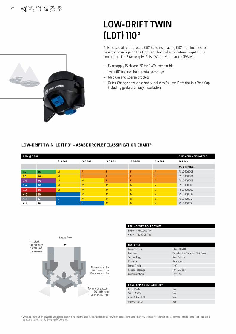
LOW-DRIFT TWIN (LDT) 110°This nozzle offers forward (30°) and rear facing (30°) fan inclines for superior coverage on the front and back of application targets. It is compatible for ExactApply, Pulse Width Modulation (PWM).
– ExactApply 15 Hz and 30 Hz PWM compatible – Twin 30° inclines for superior coverage – Medium and Coarse droplets – Quick Change nozzle assembly includes 2x Low-Drift tips in a Twin Cap
including gasket for easy installation
LOW-DRIFT TWIN (LDT) 110° – ASABE DROPLET CLASSIFICATION CHART*
LPM @ 3 BAR QUICK CHANGE NOZZLE
2.0 BAR 3.0 BAR 4.0 BAR 5.0 BAR 6.0 BAR 10 PACK
W/ STRAINER
1.2 03 M F F F F PSLDTQ1003
1.6 04 M F F F F PSLDTQ1004
2.0 05 M M F F F PSLDTQ1005
2.4 06 M M M M M PSLDTQ1006
3.2 08 M M M M M PSLDTQ1008
4.0 10 C M M M M PSLDTQ1010
4.8 12 C M M M M PSLDTQ1012
6.4 16 C C M M M PSLDTQ1016
FEATURESCommon Use Plant HealthPattern Twin Incline Tapered Flat FansTechnology Pre-OrificeMaterial PolyacetalSpray Angle 110°Pressure Range 1.0–6.0 barConfiguration FastCap
EXACTAPPLY COMPATIBILITY15 Hz PWM Yes30 Hz PWM YesAutoSelect A/B YesConventional Yes
Liquid flowSnaplock cap for easy installation and removal
REPLACEMENT CAP GASKETEPDM – PM200040-1Viton – PM200040V1
* When deciding which nozzle to use, please bear in mind that the application rate tables are for water. Because the specific gravity of liquid fertiliser is higher, a correction factor needs to be applied to select the correct nozzle. See page 11 for details.
Non air inducted twin pre-orifice
PWM compatible
Twin spray patterns 30° offset for
superior coverage
26
TIP SIZE (TWIN ASSEMBLY)
ASABE DROPLET SIZE
PRESSURE (BAR)
FLOW RATE (LPM)
APPLICATION RATE L/HA – 50 CM SPACING KM/H
3 4 6 7 8 10 12 15 20 25 30
2 X 015
M 1 0.693 277 208 139 119 104 83 69 55 42 33 28M 1.5 0.849 339 255 170 145 127 102 85 68 51 41 34M 2 0.980 392 294 196 168 147 118 98 78 59 47 39F 3 1.200 480 360 240 206 180 144 120 96 72 58 48F 4 1.386 554 416 277 238 208 166 139 111 83 67 55F 5 1.549 620 465 310 266 232 186 155 124 93 74 62F 6 1.697 679 509 339 291 255 204 170 136 102 81 68
2 X 02
M 1 0.924 370 277 185 158 139 111 92 74 55 44 37M 1.5 1.131 453 339 226 194 170 136 113 91 68 54 45M 2 1.306 523 392 261 224 196 157 131 105 78 63 52F 3 1.600 640 480 320 274 240 192 160 128 96 77 64F 4 1.848 739 554 370 317 277 222 185 148 111 89 74F 5 2.066 826 620 413 354 310 248 207 165 124 99 83F 6 2.263 905 679 453 388 339 272 226 181 136 109 91
2 X 025
M 1 1.155 462 346 231 198 173 139 115 92 69 55 46M 1.5 1.414 566 424 283 242 212 170 141 113 85 68 57M 2 1.633 653 490 327 280 245 196 163 131 98 78 65M 3 2.000 800 600 400 343 300 240 200 160 120 96 80F 4 2.309 924 693 462 396 346 277 231 185 139 111 92F 5 2.582 1,033 775 516 443 387 310 258 207 155 124 103F 6 2.828 1,131 849 566 485 424 339 283 226 170 136 113
2 X 03
C 1 1.386 554 416 277 238 208 166 139 111 83 67 55M 1.5 1.697 679 509 339 291 255 204 170 136 102 81 68M 2 1.960 784 588 392 336 294 235 196 157 118 94 78M 3 2.400 960 720 480 411 360 288 240 192 144 115 96M 4 2.771 1,109 831 554 475 416 333 277 222 166 133 111M 5 3.098 1,239 930 620 531 465 372 310 248 186 149 124M 6 3.394 1,358 1,018 679 582 509 407 339 272 204 163 136
2 X 04
C 1 1.848 739 554 370 317 277 222 185 148 111 89 74M 1.5 2.263 905 679 453 388 339 272 226 181 136 109 91M 2 2.613 1,045 784 523 448 392 314 261 209 157 125 105M 3 3.200 1,280 960 640 549 480 384 320 256 192 154 128M 4 3.695 1,478 1,109 739 633 554 443 370 296 222 177 148M 5 4.131 1,652 1,239 826 708 620 496 413 330 248 198 165M 6 4.525 1,810 1,358 905 776 679 543 453 362 272 217 181
2 X 05
C 1 2.309 924 693 462 396 346 277 231 185 139 111 92C 1.5 2.828 1,131 849 566 485 424 339 283 226 170 136 113C 2 3.266 1,306 980 653 560 490 392 327 261 196 157 131M 3 4.000 1,600 1,200 800 686 600 480 400 320 240 192 160M 4 4.619 1,848 1,386 924 792 693 554 462 370 277 222 185M 5 5.164 2,066 1,549 1,033 885 775 620 516 413 310 248 207M 6 5.657 2,263 1,697 1,131 970 849 679 566 453 339 272 226
2 X 06
C 1 2.771 1,109 831 554 475 416 333 277 222 166 133 111C 1.5 3.394 1,358 1,018 679 582 509 407 339 272 204 163 136C 2 3.919 1,568 1,176 784 672 588 470 392 314 235 188 157M 3 4.800 1,920 1,440 960 823 720 576 480 384 288 230 192M 4 5.543 2,217 1,663 1,109 950 831 665 554 443 333 266 222M 5 6.197 2,479 1,859 1,239 1,062 930 744 620 496 372 297 248M 6 6.788 2,715 2,036 1,358 1,164 1,018 815 679 543 407 326 272
2 X 08
C 1 3.695 1,478 1,109 739 633 554 443 370 296 222 177 148C 1.5 4.525 1,810 1,358 905 776 679 543 453 362 272 217 181C 2 5.226 2,090 1,568 1,045 896 784 627 523 418 314 251 209C 3 6.400 2,560 1,920 1,280 1,097 960 768 640 512 384 307 256M 4 7.390 2,956 2,217 1,478 1,267 1,109 887 739 591 443 355 296M 5 8.262 3,305 2,479 1,652 1,416 1,239 991 826 661 496 397 330M 6 9.051 3,620 2,715 1,810 1,552 1,358 1,086 905 724 543 434 362
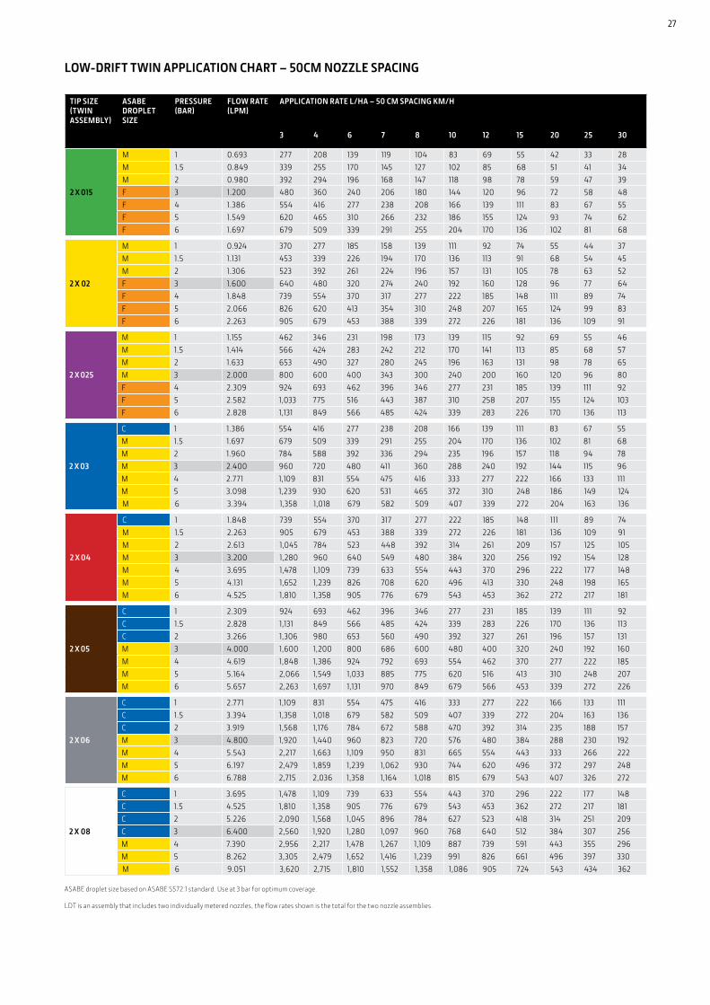
ASABE droplet size based on ASABE S572.1 standard. Use at 3 bar for optimum coverage.
LDT is an assembly that includes two individually metered nozzles, the flow rates shown is the total for the two nozzle assemblies.
LOW-DRIFT TWIN APPLICATION CHART – 50CM NOZZLE SPACING
27
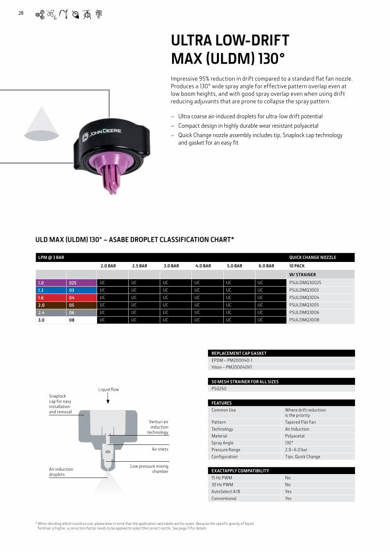
ULTRA LOW-DRIFT MAX (ULDM) 130°Impressive 95% reduction in drift compared to a standard flat fan nozzle. Produces a 130° wide spray angle for effective pattern overlap even at low boom heights, and with good spray overlap even when using drift reducing adjuvants that are prone to collapse the spray pattern.
– Ultra coarse air-induced droplets for ultra-low drift potential – Compact design in highly durable wear resistant polyacetal – Quick Change nozzle assembly includes tip, Snaplock cap technology
and gasket for an easy fit
ULD MAX (ULDM) 130° – ASABE DROPLET CLASSIFICATION CHART*
Liquid flowSnaplock cap for easy installation and removal
Air induction droplets
Venturi air induction
technology
Low pressure mixing chamber
Air inlets
LPM @ 3 BAR QUICK CHANGE NOZZLE
2.0 BAR 2.5 BAR 3.0 BAR 4.0 BAR 5.0 BAR 6.0 BAR 10 PACK
W/ STRAINER
1.0 025 UC UC UC UC UC UC PSULDMQ30025
1.2 03 UC UC UC UC UC UC PSULDMQ3003
1.6 04 UC UC UC UC UC UC PSULDMQ3004
2.0 05 UC UC UC UC UC UC PSULDMQ3005
2.4 06 UC UC UC UC UC UC PSULDMQ3006
3.0 08 UC UC UC UC UC UC PSULDMQ3008
FEATURESCommon Use Where drift reduction
is the priorityPattern Tapered Flat FanTechnology Air InductionMaterial PolyacetalSpray Angle 130°Pressure Range 2.0–6.0 barConfiguration Tips, Quick Change
EXACTAPPLY COMPATIBILITY15 Hz PWM No30 Hz PWM NoAutoSelect A/B YesConventional Yes
50 MESH STRAINER FOR ALL SIZESPS0250
REPLACEMENT CAP GASKETEPDM – PM200040-1Viton – PM200040V1
* When deciding which nozzle to use, please bear in mind that the application rate tables are for water. Because the specific gravity of liquid fertiliser is higher, a correction factor needs to be applied to select the correct nozzle. See page 11 for details
28
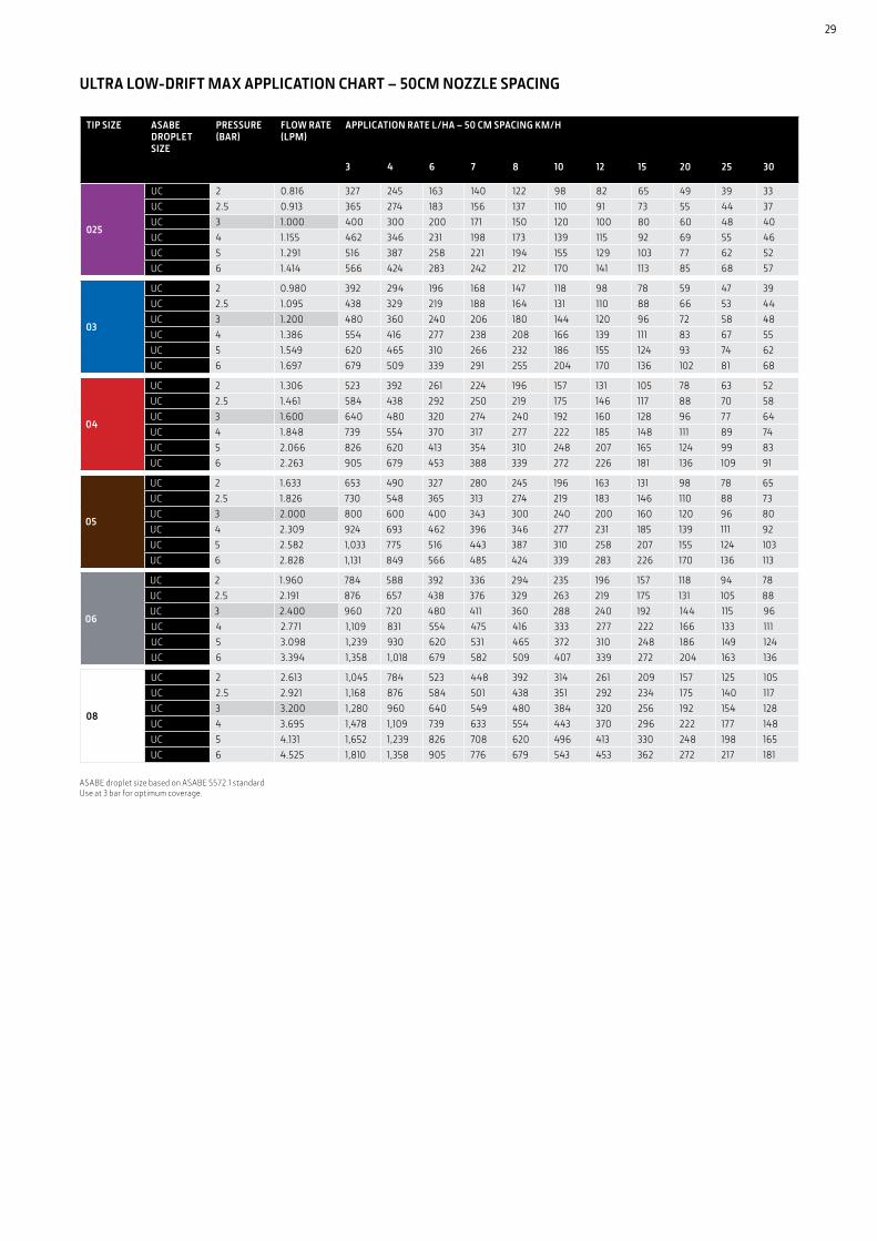
TIP SIZE ASABE DROPLET SIZE
PRESSURE (BAR)
FLOW RATE (LPM)
APPLICATION RATE L/HA – 50 CM SPACING KM/H
3 4 6 7 8 10 12 15 20 25 30
025
UC 2 0.816 327 245 163 140 122 98 82 65 49 39 33UC 2.5 0.913 365 274 183 156 137 110 91 73 55 44 37UC 3 1.000 400 300 200 171 150 120 100 80 60 48 40UC 4 1.155 462 346 231 198 173 139 115 92 69 55 46UC 5 1.291 516 387 258 221 194 155 129 103 77 62 52UC 6 1.414 566 424 283 242 212 170 141 113 85 68 57
03
UC 2 0.980 392 294 196 168 147 118 98 78 59 47 39UC 2.5 1.095 438 329 219 188 164 131 110 88 66 53 44UC 3 1.200 480 360 240 206 180 144 120 96 72 58 48UC 4 1.386 554 416 277 238 208 166 139 111 83 67 55UC 5 1.549 620 465 310 266 232 186 155 124 93 74 62UC 6 1.697 679 509 339 291 255 204 170 136 102 81 68
04
UC 2 1.306 523 392 261 224 196 157 131 105 78 63 52UC 2.5 1.461 584 438 292 250 219 175 146 117 88 70 58UC 3 1.600 640 480 320 274 240 192 160 128 96 77 64UC 4 1.848 739 554 370 317 277 222 185 148 111 89 74UC 5 2.066 826 620 413 354 310 248 207 165 124 99 83UC 6 2.263 905 679 453 388 339 272 226 181 136 109 91
05
UC 2 1.633 653 490 327 280 245 196 163 131 98 78 65UC 2.5 1.826 730 548 365 313 274 219 183 146 110 88 73UC 3 2.000 800 600 400 343 300 240 200 160 120 96 80UC 4 2.309 924 693 462 396 346 277 231 185 139 111 92UC 5 2.582 1,033 775 516 443 387 310 258 207 155 124 103UC 6 2.828 1,131 849 566 485 424 339 283 226 170 136 113
06
UC 2 1.960 784 588 392 336 294 235 196 157 118 94 78UC 2.5 2.191 876 657 438 376 329 263 219 175 131 105 88UC 3 2.400 960 720 480 411 360 288 240 192 144 115 96UC 4 2.771 1,109 831 554 475 416 333 277 222 166 133 111UC 5 3.098 1,239 930 620 531 465 372 310 248 186 149 124UC 6 3.394 1,358 1,018 679 582 509 407 339 272 204 163 136
08
UC 2 2.613 1,045 784 523 448 392 314 261 209 157 125 105UC 2.5 2.921 1,168 876 584 501 438 351 292 234 175 140 117UC 3 3.200 1,280 960 640 549 480 384 320 256 192 154 128UC 4 3.695 1,478 1,109 739 633 554 443 370 296 222 177 148UC 5 4.131 1,652 1,239 826 708 620 496 413 330 248 198 165UC 6 4.525 1,810 1,358 905 776 679 543 453 362 272 217 181
ULTRA LOW-DRIFT MAX APPLICATION CHART – 50CM NOZZLE SPACING
ASABE droplet size based on ASABE S572.1 standardUse at 3 bar for optimum coverage.
29

* When deciding which nozzle to use, please bear in mind that the application rate tables are for water. Because the specific gravity of liquid fertiliser is higher, a correction factor needs to be applied to select the correct nozzle. See page 11 for details.
ULTRA LOW-DRIFT (ULD) 120°The ideal nozzle for pre-and post-emergence applications where drift reduction is paramount. A spray pattern measuring nearly 60° front to back, and the 120° wide spray angle enable lower boom height for even less drift potential.
– Creates air-induced droplets to significantly reduce spray drift potential – Small, compact size reduces the chance of accidental breakage – Moulded from wear resistant polyacetal for increased durability – Quick Change nozzle assembly includes tip, cap and gasket for sizes
015–08, including 025
LPM @ 3 BAR QUICK CHANGE NOZZLE
2.0 BAR
2.5 BAR
3.0 BAR
3.5 BAR
4.0 BAR
4.5 BAR
5.0 BAR
5.5 BAR
6.0 BAR
6.5 BAR
7.0 BAR
7.5 BAR
8.0 BAR
10 PACK
W/ STRAINER
0.6 015 EC EC VC VC C C C C M M M M M PSULDQ20015
0.8 02 EC VC C C C M M M M M M M M PSULDQ2002
1.0 025 EC VC C C C M M M M M M M M PSULDQ20025
1.2 03 EC VC C C C M M M M M M M M PSULDQ2003
1.6 04 UC UC UC EC EC EC EC VC VC VC C C C PSULDQ2004
2.0 05 UC EC EC EC EC EC VC VC VC VC C C C PSULDQ2005
2.4 06 UC EC EC EC VC VC C C C C C C M PSULDQ2006
3.2 08 EC EC VC VC C C C C M M M M M PSULDQ2008
FEATURESCommon Use WeedsPattern Tapered Flat FanTechnology Air InductionMaterial PolyacetalSpray Angle 120°Pressure Range 2.0–8.0 barConfiguration Tips, Quick Change
EXACTAPPLY COMPATIBILITY15 Hz PWM No30 Hz PWM NoAutoSelect A/B YesConventional Yes
50 MESH STRAINER FOR ALL SIZESPS310
REPLACEMENT CAP GASKET (WITHOUT STRAINER)EPDM PM200040-1Viton PM200040V1
REPLACEMENT CAP GASKET (WITH STRAINER)PS17000255
Liquid stream
Mixing chamber
Air inclusion droplets
Air inlets
ULD 120 DEG. – ASABE DROPLET CLASSIFICATION CHART*
30

Droplet size based on ASABE S572.1 standardUse at 3 bar for optimum coverage.
ULTRA LOW-DRIFT APPLICATION CHART – 50CM NOZZLE SPACING
TIP SIZE
ASABE DROPLET SIZE
PRESSURE (BAR)
FLOW RATE (LPM)
APPLICATION RATE L/HA – 50 CM SPACING KM/H
3 4 6 7 8 10 12 15 20 25 30
015
EC 2 0.490 196 147 98 84 73 59 49 39 29 24 20VC 3 0.600 240 180 120 103 90 72 60 48 36 29 24C 4 0.693 277 208 139 119 104 83 69 55 42 33 28C 5 0.775 310 232 155 133 116 93 77 62 46 37 31M 6 0.849 339 255 170 145 127 102 85 68 51 41 34M 7 0.917 367 275 183 157 137 110 92 73 55 44 37M 8 0.980 392 294 196 168 147 118 98 78 59 47 39
02
EC 2 0.653 261 196 131 112 98 78 65 52 39 31 26VC 3 0.800 320 240 160 137 120 96 80 64 48 38 32C 4 0.924 370 277 185 158 139 111 92 74 55 44 37M 5 1.033 413 310 207 177 155 124 103 83 62 50 41M 6 1.131 453 339 226 194 170 136 113 91 68 54 45M 7 1.222 489 367 244 209 183 147 122 98 73 59 49M 8 1.306 523 392 261 224 196 157 131 105 78 63 52
025
EC 2 0.816 327 245 163 140 122 98 82 65 49 39 33VC 3 1.000 400 300 200 171 150 120 100 80 60 48 40C 4 1.155 462 346 231 198 173 139 115 92 69 55 46M 5 1.291 516 387 258 221 194 155 129 103 77 62 52M 6 1.414 566 424 283 242 212 170 141 113 85 68 57M 7 1.528 611 458 306 262 229 183 153 122 92 73 61M 8 1.633 653 490 327 280 245 196 163 131 98 78 65
03
EC 2 0.980 392 294 196 168 147 118 98 78 59 47 39VC 3 1.200 480 360 240 206 180 144 120 96 72 58 48C 4 1.386 554 416 277 238 208 166 139 111 83 67 55M 5 1.549 620 465 310 266 232 186 155 124 93 74 62M 6 1.697 679 509 339 291 255 204 170 136 102 81 68M 7 1.833 733 550 367 314 275 220 183 147 110 88 73M 8 1.960 784 588 392 336 294 235 196 157 118 94 78
04
UC 2 1.306 523 392 261 224 196 157 131 105 78 63 52UC 3 1.600 640 480 320 274 240 192 160 128 96 77 64EC 4 1.848 739 554 370 317 277 222 185 148 111 89 74EC 5 2.066 826 620 413 354 310 248 207 165 124 99 83VC 6 2.263 905 679 453 388 339 272 226 181 136 109 91C 7 2.444 978 733 489 419 367 293 244 196 147 117 98C 8 2.613 1,045 784 523 448 392 314 261 209 157 125 105
05
UC 2 1.633 653 490 327 280 245 196 163 131 98 78 65EC 3 2.000 800 600 400 343 300 240 200 160 120 96 80EC 4 2.309 924 693 462 396 346 277 231 185 139 111 92VC 5 2.582 1,033 775 516 443 387 310 258 207 155 124 103VC 6 2.828 1,131 849 566 485 424 339 283 226 170 136 113C 7 3.055 1,222 917 611 524 458 367 306 244 183 147 122C 8 3.266 1,306 980 653 560 490 392 327 261 196 157 131
06
UC 2 1.960 784 588 392 336 294 235 196 157 118 94 78EC 3 2.400 960 720 480 411 360 288 240 192 144 115 96VC 4 2.771 1,109 831 554 475 416 333 277 222 166 133 111C 5 3.098 1,239 930 620 531 465 372 310 248 186 149 124C 6 3.394 1,358 1,018 679 582 509 407 339 272 204 163 136C 7 3.666 1,466 1,100 733 628 550 440 367 293 220 176 147M 8 3.919 1,568 1,176 784 672 588 470 392 314 235 188 157
08
EC 2 1.960 1,045 784 523 448 392 314 261 209 157 125 105VC 3 2.400 1,280 960 640 549 480 384 320 256 192 154 128C 4 2.771 1,478 1,109 739 633 554 443 370 296 222 177 148C 5 3.098 1,652 1,239 826 708 620 496 413 330 248 198 165M 6 3.394 1,810 1,358 905 776 679 543 453 362 272 217 181M 7 3.666 1,955 1,466 978 838 733 587 489 391 293 235 196M 8 3.919 2,090 1,568 1,045 896 784 627 523 418 314 251 209
31

GUARDIANAIR TWIN™ (GAT) 110°GuardianAIR Twin™ spray nozzles are the best choice for applications to broad-leaved crops, tall plants and cereal ear sprays. The GAT is ideal for penetrating dense canopies with great coverage and reduced drift.
– High-coverage forward (30°) and rear facing (30°) fans help penetrate dense canopies such as vegetables and oilseed crops
– Wide speed range while maintaining consistent spray efficiency – Easy to install, locking ring and O-ring seal design – Single orifice design, wear-resistant polyacetal for durability – Quick Change nozzle assembly includes tips, cap, gasket and cage
FEATURESCommon Use Plant HealthPattern Tapered Flat FanTechnology Air InductionMaterial PolyacetalSpray Angle 110°Pressure Range 1.5–6.0 barConfiguration Quick Change
EXACTAPPLY COMPATIBILITY15 Hz PWM No30 Hz PWM NoAutoSelect A/B YesConventional Yes
REPLACEMENT CAP GASKETPM65BS205
50 MESH STRAINER FOR ALL SIZESPS0250
REPLACEMENT CAGEPS30Q3579A
LPM @ 3 BAR QUICK CHANGE NOZZLE
2.0 BAR 2.5 BAR 3.0 BAR 3.5 BAR 4.0 BAR 4.5 BAR 5.0 BAR 5.5 BAR 6.0 BAR 10 PACK
W/ STRAINER
0.8 02 C C M M M M M M M PSGAT1002
1.0 025 VC VC C C M M M M M PSGAT10025
1.2 03 VC VC C C M M M M M PSGAT1003
1.4 035 EC VC C C M M M M M PSGAT10035
1.6 04 C C M M M M M M M PSGAT1004
2.0 05 VC VC C C M M M M M PSGAT1005
2.4 06 VC VC C C C M M M M PSGAT1006
3.2 08 VC VC VC C C C C M M PSGAT1008
GAT 110 DEG.– ASABE DROPLET CLASSIFICATION CHART*
* When deciding which nozzle to use, please bear in mind that the application rate tables are for water. Because the specific gravity of liquid fertiliser is higher, a correction factor needs to be applied to select the correct nozzle. See page 11 for details.
Air inlets
Mixing chamber
Air inclusion droplets
Pre-orifice
Air inlets
Liquid flow
32

Droplet size based on ASABE S572.1 standard. Use at 3 bar for optimum coverage.
Whilst GAT nozzles have twin outlets, the flow is metered through a single orifice and as a consequence the flows given in the table are the total for the nozzle.
GUARDIANAIR TWIN APPLICATION CHART – 50CM NOZZLE SPACING
TIP SIZE
ASABE DROPLET SIZE
PRESSURE (BAR)
FLOW RATE (LPM)
APPLICATION RATE L/HA – 50 CM SPACING KM/H
3 4 5 7 8 10 12 15 20 25 30
02
C 2 0.653 261 196 131 112 98 78 65 52 39 31 26M 3 0.800 320 240 160 137 120 96 80 64 48 38 32M 4 0.924 370 277 185 158 139 111 92 74 55 44 37M 5 1.033 413 310 207 177 155 124 103 83 62 50 41M 6 1.131 453 339 226 194 170 136 113 91 68 54 45F 7 1.222 489 367 244 209 183 147 122 98 73 59 49F 8 1.306 523 392 261 224 196 157 131 105 78 63 52
025
UC 2 0.816 327 245 163 140 122 98 82 65 49 39 33VC 3 1.000 400 300 200 171 150 120 100 80 60 48 40M 4 1.155 462 346 231 198 173 139 115 92 69 55 46M 5 1.291 516 387 258 221 194 155 129 103 77 62 52M 6 1.414 566 424 283 242 212 170 141 113 85 68 57M 7 1.528 611 458 306 262 229 183 153 122 92 73 61M 8 1.633 653 490 327 280 245 196 163 131 98 78 65
03
VC 2 0.980 392 294 196 168 147 118 98 78 59 47 39C 3 1.200 480 360 240 206 180 144 120 96 72 58 48M 4 1.386 554 416 277 238 208 166 139 111 83 67 55M 5 1.549 620 465 310 266 232 186 155 124 93 74 62M 6 1.697 679 509 339 291 255 204 170 136 102 81 68M 7 1.833 733 550 367 314 275 220 183 147 110 88 73M 8 1.960 784 588 392 336 294 235 196 157 118 94 78
035
EC 2 1.143 457 343 229 196 171 137 114 91 69 55 46C 3 1.400 560 420 280 240 210 168 140 112 84 67 56M 4 1.617 647 485 323 277 242 194 162 129 97 78 65M 5 1.807 723 542 361 310 271 217 181 145 108 87 72M 6 1.980 792 594 396 339 297 238 198 158 119 95 79M 7 2.139 855 642 428 367 321 257 214 171 128 103 86M 8 2.286 914 686 457 392 343 274 229 183 137 110 91
04
VC 2 1.306 523 392 261 224 196 157 131 105 78 63 52C 3 1.600 640 480 320 274 240 192 160 128 96 77 64M 4 1.848 739 554 370 317 277 222 185 148 111 89 74M 5 2.066 826 620 413 354 310 248 207 165 124 99 83M 6 2.263 905 679 453 388 339 272 226 181 136 109 91M 7 2.444 978 733 489 419 367 293 244 196 147 117 98M 8 2.613 1,045 784 523 448 392 314 261 209 157 125 105
05
VC 2 1.633 653 490 327 280 245 196 163 131 98 78 65C 3 2.000 800 600 400 343 300 240 200 160 120 96 80M 4 2.309 924 693 462 396 346 277 231 185 139 111 92M 5 2.582 1,033 775 516 443 387 310 258 207 155 124 103M 6 2.828 1,131 849 566 485 424 339 283 226 170 136 113M 7 3.055 1,222 917 611 524 458 367 306 244 183 147 122M 8 3.266 1,306 980 653 560 490 392 327 261 196 157 131
06
EC 2 1.960 784 588 392 336 294 235 196 157 118 94 78C 3 2.400 960 720 480 411 360 288 240 192 144 115 96C 4 2.771 1,109 831 554 475 416 333 277 222 166 133 111M 5 3.098 1,239 930 620 531 465 372 310 248 186 149 124M 6 3.394 1,358 1,018 679 582 509 407 339 272 204 163 136M 7 3.666 1,466 1,100 733 628 550 440 367 293 220 176 147M 8 3.919 1,568 1,176 784 672 588 470 392 314 235 188 157
08
VC 2 2.613 1,045 784 523 448 392 314 261 209 157 125 105C 3 3.200 1,280 960 640 549 480 384 320 256 192 154 128C 4 3.695 1,478 1,109 739 633 554 443 370 296 222 177 148M 5 4.131 1,652 1,239 826 708 620 496 413 330 248 198 165M 6 4.525 1,810 1,358 905 776 679 543 453 362 272 217 181M 7 4.888 1,955 1,466 978 838 733 587 489 391 293 235 196M 8 5.226 2,090 1,568 1,045 896 784 627 523 418 314 251 209
C
33

34
LPM @ 3 BAR QUICK CHANGE NOZZLE
1.5 BAR 2.0 BAR 2.5 BAR 3.0 BAR 3.5 BAR 4.0 BAR 4.5 BAR 5.0 BAR 5.5 BAR 6.0 BAR 10 PACK
0.6 015 UC EC VC C C M M M M M PSLDAQ10015
0.8 02 EC VC C M M M M M M M PSLDAQ1002
1.0 025 EC VC C C M M M M M M PSLDAQ10025
1.2 03 UC EC VC VC C C C M M M PSLDAQ1003
1.4 035 EC VC C C C M M M M M PSLDAQ10035
1.6 04 EC VC C C C M M M M M PSLDAQ1004
2.0 05 EC EC VC C C C M M M M PSLDAQ1005
LOW-DRIFT AIR (LDA) 110°LDA nozzles offer proven spray coverage of a wide range of targets in spring applications at 3 bar pressure, regardless of nozzle size selected.
– Air-induced droplets reduce drift and increase deposition/retention – Better coverage with more drops per litre compared to other common
air-induced spray nozzles – Moulded from a wear-resistant polyacetal for increased durability – Quick Change nozzle assembly includes tip, cap and gasket – Rearwards incline compensates for sprayer forward motion for
uniform coverage
LDA 110 DEG. – ASABE DROPLET CLASSIFCIATION CHART*
FEATURESCommon Use Plant HealthPattern Tapered Flat FanTechnology Air InductionMaterial PolyacetalSpray Angle 110°Pressure Range 1.0–6.0 barConfiguration Quick Change
EXACTAPPLY COMPATIBILITY15 Hz PWM No 30 Hz PWM NoAutoSelect A/B YesConventional Yes
REPLACEMENT CAP GASKETEPDM PM200040-1Viton PM200040V1
Low pressure mixing chamber
Air inlets
Air inclusion droplets
Air inlets
Venturi
Liquid flow
* When deciding which nozzle to use, please bear in mind that the application rate tables are for water. Because the specific gravity of liquid fertiliser is higher, a correction factor needs to be applied to select the correct nozzle. See page 11 for details.
34
35
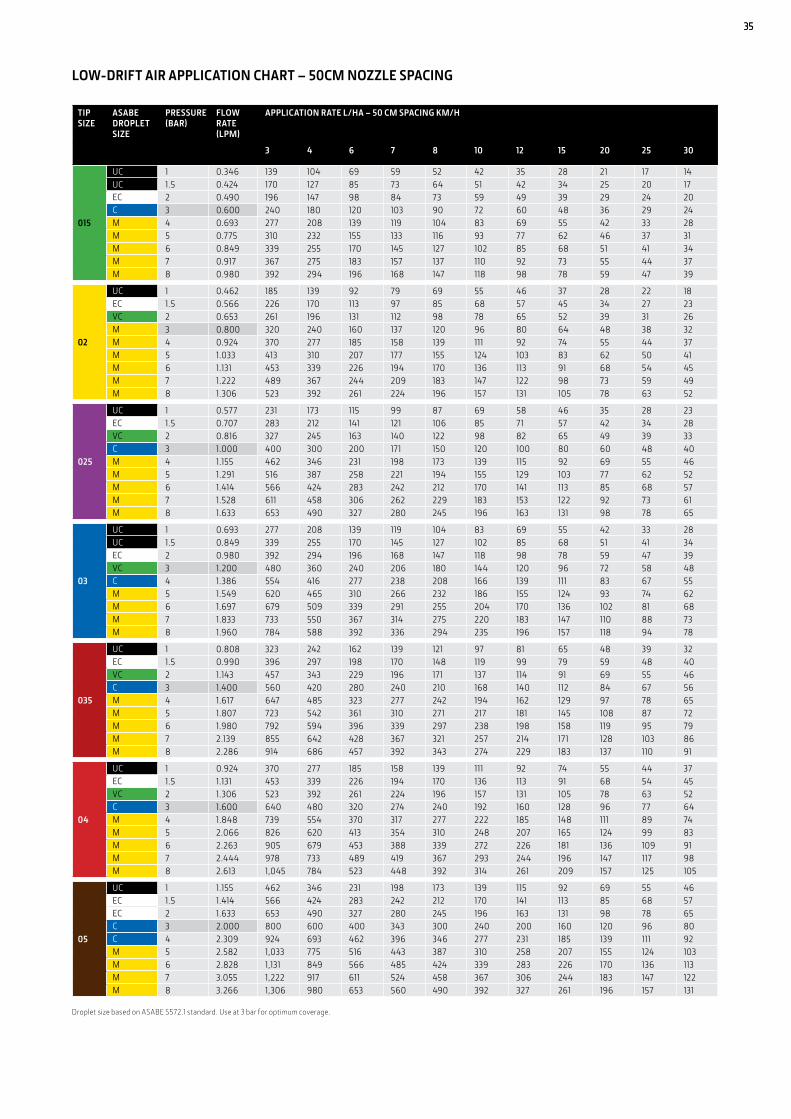
Droplet size based on ASABE S572.1 standard. Use at 3 bar for optimum coverage.
LOW-DRIFT AIR APPLICATION CHART – 50CM NOZZLE SPACING
TIP SIZE
ASABE DROPLET SIZE
PRESSURE (BAR)
FLOW RATE (LPM)
APPLICATION RATE L/HA – 50 CM SPACING KM/H
3 4 6 7 8 10 12 15 20 25 30
015
UC 1 0.346 139 104 69 59 52 42 35 28 21 17 14UC 1.5 0.424 170 127 85 73 64 51 42 34 25 20 17EC 2 0.490 196 147 98 84 73 59 49 39 29 24 20C 3 0.600 240 180 120 103 90 72 60 48 36 29 24M 4 0.693 277 208 139 119 104 83 69 55 42 33 28M 5 0.775 310 232 155 133 116 93 77 62 46 37 31M 6 0.849 339 255 170 145 127 102 85 68 51 41 34M 7 0.917 367 275 183 157 137 110 92 73 55 44 37M 8 0.980 392 294 196 168 147 118 98 78 59 47 39
02
UC 1 0.462 185 139 92 79 69 55 46 37 28 22 18EC 1.5 0.566 226 170 113 97 85 68 57 45 34 27 23VC 2 0.653 261 196 131 112 98 78 65 52 39 31 26M 3 0.800 320 240 160 137 120 96 80 64 48 38 32M 4 0.924 370 277 185 158 139 111 92 74 55 44 37M 5 1.033 413 310 207 177 155 124 103 83 62 50 41M 6 1.131 453 339 226 194 170 136 113 91 68 54 45M 7 1.222 489 367 244 209 183 147 122 98 73 59 49M 8 1.306 523 392 261 224 196 157 131 105 78 63 52
025
UC 1 0.577 231 173 115 99 87 69 58 46 35 28 23EC 1.5 0.707 283 212 141 121 106 85 71 57 42 34 28VC 2 0.816 327 245 163 140 122 98 82 65 49 39 33C 3 1.000 400 300 200 171 150 120 100 80 60 48 40M 4 1.155 462 346 231 198 173 139 115 92 69 55 46M 5 1.291 516 387 258 221 194 155 129 103 77 62 52M 6 1.414 566 424 283 242 212 170 141 113 85 68 57M 7 1.528 611 458 306 262 229 183 153 122 92 73 61M 8 1.633 653 490 327 280 245 196 163 131 98 78 65
03
UC 1 0.693 277 208 139 119 104 83 69 55 42 33 28UC 1.5 0.849 339 255 170 145 127 102 85 68 51 41 34EC 2 0.980 392 294 196 168 147 118 98 78 59 47 39VC 3 1.200 480 360 240 206 180 144 120 96 72 58 48C 4 1.386 554 416 277 238 208 166 139 111 83 67 55M 5 1.549 620 465 310 266 232 186 155 124 93 74 62M 6 1.697 679 509 339 291 255 204 170 136 102 81 68M 7 1.833 733 550 367 314 275 220 183 147 110 88 73M 8 1.960 784 588 392 336 294 235 196 157 118 94 78
035
UC 1 0.808 323 242 162 139 121 97 81 65 48 39 32EC 1.5 0.990 396 297 198 170 148 119 99 79 59 48 40VC 2 1.143 457 343 229 196 171 137 114 91 69 55 46C 3 1.400 560 420 280 240 210 168 140 112 84 67 56M 4 1.617 647 485 323 277 242 194 162 129 97 78 65M 5 1.807 723 542 361 310 271 217 181 145 108 87 72M 6 1.980 792 594 396 339 297 238 198 158 119 95 79M 7 2.139 855 642 428 367 321 257 214 171 128 103 86M 8 2.286 914 686 457 392 343 274 229 183 137 110 91
04
UC 1 0.924 370 277 185 158 139 111 92 74 55 44 37EC 1.5 1.131 453 339 226 194 170 136 113 91 68 54 45VC 2 1.306 523 392 261 224 196 157 131 105 78 63 52C 3 1.600 640 480 320 274 240 192 160 128 96 77 64M 4 1.848 739 554 370 317 277 222 185 148 111 89 74M 5 2.066 826 620 413 354 310 248 207 165 124 99 83M 6 2.263 905 679 453 388 339 272 226 181 136 109 91M 7 2.444 978 733 489 419 367 293 244 196 147 117 98M 8 2.613 1,045 784 523 448 392 314 261 209 157 125 105
05
UC 1 1.155 462 346 231 198 173 139 115 92 69 55 46EC 1.5 1.414 566 424 283 242 212 170 141 113 85 68 57EC 2 1.633 653 490 327 280 245 196 163 131 98 78 65C 3 2.000 800 600 400 343 300 240 200 160 120 96 80C 4 2.309 924 693 462 396 346 277 231 185 139 111 92M 5 2.582 1,033 775 516 443 387 310 258 207 155 124 103M 6 2.828 1,131 849 566 485 424 339 283 226 170 136 113M 7 3.055 1,222 917 611 524 458 367 306 244 183 147 122M 8 3.266 1,306 980 653 560 490 392 327 261 196 157 131
35
ExtendedRange
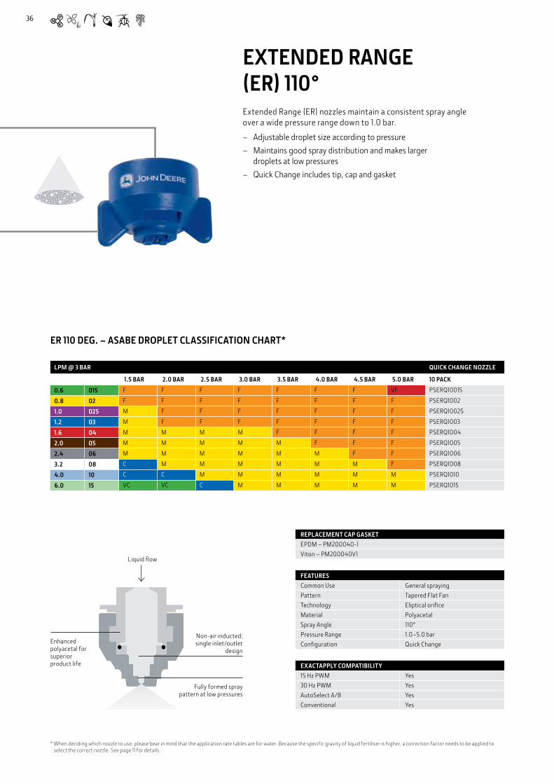
EXTENDED RANGE (ER) 110°Extended Range (ER) nozzles maintain a consistent spray angle over a wide pressure range down to 1.0 bar.
– Adjustable droplet size according to pressure – Maintains good spray distribution and makes larger
droplets at low pressures – Quick Change includes tip, cap and gasket
FEATURESCommon Use General sprayingPattern Tapered Flat FanTechnology Eliptical orificeMaterial PolyacetalSpray Angle 110°Pressure Range 1.0–5.0 barConfiguration Quick Change
EXACTAPPLY COMPATIBILITY15 Hz PWM Yes30 Hz PWM YesAutoSelect A/B YesConventional Yes
REPLACEMENT CAP GASKETEPDM – PM200040-1Viton – PM200040V1
LPM @ 3 BAR QUICK CHANGE NOZZLE
1.5 BAR 2.0 BAR 2.5 BAR 3.0 BAR 3.5 BAR 4.0 BAR 4.5 BAR 5.0 BAR 10 PACK
0.6 015 F F F F F F F VF PSERQ10015
0.8 02 F F F F F F F F PSERQ1002
1.0 025 M F F F F F F F PSERQ10025
1.2 03 M F F F F F F F PSERQ1003
1.6 04 M M M M F F F F PSERQ1004
2.0 05 M M M M M F F F PSERQ1005
2.4 06 M M M M M M F F PSERQ1006
3.2 08 C M M M M M M F PSERQ1008
4.0 10 C C M M M M M M PSERQ1010
6.0 15 VC VC C M M M M M PSERQ1015
ER 110 DEG. – ASABE DROPLET CLASSIFICATION CHART*
* When deciding which nozzle to use, please bear in mind that the application rate tables are for water. Because the specific gravity of liquid fertiliser is higher, a correction factor needs to be applied to select the correct nozzle. See page 11 for details.
Non-air inducted; single inlet/outlet
design
Fully formed spray pattern at low pressures
Enhanced polyacetal for superior product life
Liquid flow
36
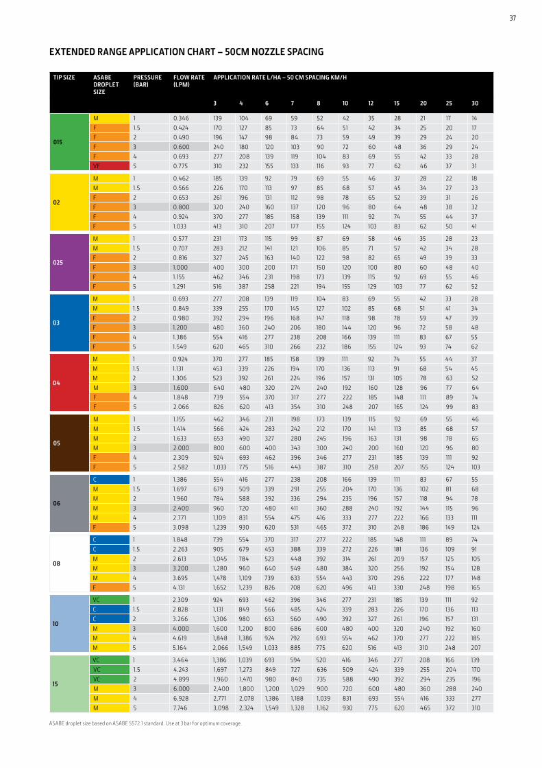
TIP SIZE ASABE DROPLET SIZE
PRESSURE (BAR)
FLOW RATE (LPM)
APPLICATION RATE L/HA – 50 CM SPACING KM/H
3 4 6 7 8 10 12 15 20 25 30
015
M 1 0.346 139 104 69 59 52 42 35 28 21 17 14F 1.5 0.424 170 127 85 73 64 51 42 34 25 20 17F 2 0.490 196 147 98 84 73 59 49 39 29 24 20F 3 0.600 240 180 120 103 90 72 60 48 36 29 24F 4 0.693 277 208 139 119 104 83 69 55 42 33 28VF 5 0.775 310 232 155 133 116 93 77 62 46 37 31
02
M 1 0.462 185 139 92 79 69 55 46 37 28 22 18M 1.5 0.566 226 170 113 97 85 68 57 45 34 27 23F 2 0.653 261 196 131 112 98 78 65 52 39 31 26F 3 0.800 320 240 160 137 120 96 80 64 48 38 32F 4 0.924 370 277 185 158 139 111 92 74 55 44 37F 5 1.033 413 310 207 177 155 124 103 83 62 50 41
025
M 1 0.577 231 173 115 99 87 69 58 46 35 28 23M 1.5 0.707 283 212 141 121 106 85 71 57 42 34 28F 2 0.816 327 245 163 140 122 98 82 65 49 39 33F 3 1.000 400 300 200 171 150 120 100 80 60 48 40F 4 1.155 462 346 231 198 173 139 115 92 69 55 46F 5 1.291 516 387 258 221 194 155 129 103 77 62 52
03
M 1 0.693 277 208 139 119 104 83 69 55 42 33 28M 1.5 0.849 339 255 170 145 127 102 85 68 51 41 34F 2 0.980 392 294 196 168 147 118 98 78 59 47 39F 3 1.200 480 360 240 206 180 144 120 96 72 58 48F 4 1.386 554 416 277 238 208 166 139 111 83 67 55F 5 1.549 620 465 310 266 232 186 155 124 93 74 62
04
M 1 0.924 370 277 185 158 139 111 92 74 55 44 37M 1.5 1.131 453 339 226 194 170 136 113 91 68 54 45M 2 1.306 523 392 261 224 196 157 131 105 78 63 52M 3 1.600 640 480 320 274 240 192 160 128 96 77 64F 4 1.848 739 554 370 317 277 222 185 148 111 89 74F 5 2.066 826 620 413 354 310 248 207 165 124 99 83
05
M 1 1.155 462 346 231 198 173 139 115 92 69 55 46M 1.5 1.414 566 424 283 242 212 170 141 113 85 68 57M 2 1.633 653 490 327 280 245 196 163 131 98 78 65M 3 2.000 800 600 400 343 300 240 200 160 120 96 80F 4 2.309 924 693 462 396 346 277 231 185 139 111 92F 5 2.582 1,033 775 516 443 387 310 258 207 155 124 103
06
C 1 1.386 554 416 277 238 208 166 139 111 83 67 55M 1.5 1.697 679 509 339 291 255 204 170 136 102 81 68M 2 1.960 784 588 392 336 294 235 196 157 118 94 78M 3 2.400 960 720 480 411 360 288 240 192 144 115 96M 4 2.771 1,109 831 554 475 416 333 277 222 166 133 111F 5 3.098 1,239 930 620 531 465 372 310 248 186 149 124
08
C 1 1.848 739 554 370 317 277 222 185 148 111 89 74C 1.5 2.263 905 679 453 388 339 272 226 181 136 109 91M 2 2.613 1,045 784 523 448 392 314 261 209 157 125 105M 3 3.200 1,280 960 640 549 480 384 320 256 192 154 128M 4 3.695 1,478 1,109 739 633 554 443 370 296 222 177 148F 5 4.131 1,652 1,239 826 708 620 496 413 330 248 198 165
10
VC 1 2.309 924 693 462 396 346 277 231 185 139 111 92C 1.5 2.828 1,131 849 566 485 424 339 283 226 170 136 113C 2 3.266 1,306 980 653 560 490 392 327 261 196 157 131M 3 4.000 1,600 1,200 800 686 600 480 400 320 240 192 160M 4 4.619 1,848 1,386 924 792 693 554 462 370 277 222 185M 5 5.164 2,066 1,549 1,033 885 775 620 516 413 310 248 207
15
VC 1 3.464 1,386 1,039 693 594 520 416 346 277 208 166 139VC 1.5 4.243 1,697 1,273 849 727 636 509 424 339 255 204 170VC 2 4.899 1,960 1,470 980 840 735 588 490 392 294 235 196M 3 6.000 2,400 1,800 1,200 1,029 900 720 600 480 360 288 240M 4 6.928 2,771 2,078 1,386 1,188 1,039 831 693 554 416 333 277M 5 7.746 3,098 2,324 1,549 1,328 1,162 930 775 620 465 372 310
ASABE droplet size based on ASABE S572.1 standard. Use at 3 bar for optimum coverage.
EXTENDED RANGE APPLICATION CHART – 50CM NOZZLE SPACING
37

38
ExtendedRange
EXTENDED RANGE CERAMIC (ERC) 110°The Extended Range Ceramic (ERC) wide pressure range ceramic spray nozzles are suited for creating numerous fine to medium droplets. The ceramic orifice of the ERC will provide long service life even when spraying abrasive chemicals.
– Adjustable droplet size according to pressure – Maintains good spray distribution and makes larger droplets
at low pressures – Quick Change includes tip, cap and gasket
ERC 110 DEG. – ASABE DROPLET CLASSIFICATION CHART*
REPLACEMENT CAP GASKETEPDM – PM200040-1Viton – PM200040V1
FEATURESCommon Use GeneralPattern Tapered Flat FanTechnology Elliptical OrificeMaterial CeramicSpray Angle 110°Pressure Range 1.5–5.0 barConfiguration Quick Change
EXACTAPPLY COMPATIBILITY15 Hz PWM Yes30 Hz PWM YesAutoSelect A/B YesConventional Yes
* When deciding which nozzle to use, please bear in mind that the application rate tables are for water. Because the specific gravity of liquid fertiliser is higher, a correction factor needs to be applied to select the correct nozzle. See page 11 for details.
Non-air inducted; single inlet/outlet
design
Fully formed spray pattern at low pressures
Enhanced polyacetal for superior product life
Liquid flow
LPM @ 3 BAR QUICK CHANGE NOZZLE
1.5 BAR 2.0 BAR 3.0 BAR 3.5 BAR 4.0 BAR 5.0 BAR 10 PACK
0.6 015 N/A F F F F F PSERCQ10015
0.8 02 N/A F F F F F PSERCQ1002
1.2 03 F F F F F F PSERCQ1003
1.6 04 M M F F F F PSERCQ1004
2.0 05 M F F F F F PSERCQ1005
2.4 06 M M M M F F PSERCQ1006
38

39
EXTENDED RANGE CERAMIC APPLICATION CHART – 50CM NOZZLE SPACING
TIP SIZE ASABE DROPLET SIZE
PRESSURE (BAR)
FLOW RATE (LPM)
APPLICATION RATE L/HA – 50 CM SPACING KM/H
3 4 6 7 8 10 12 15 20 25 30
015
N/A 1 0.346 139 104 69 59 52 42 35 28 21 17 14N/A 1.5 0.424 170 127 85 73 64 51 42 34 25 20 17F 2 0.490 196 147 98 84 73 59 49 39 29 24 20F 3 0.600 240 180 120 103 90 72 60 48 36 29 24F 4 0.693 277 208 139 119 104 83 69 55 42 33 28F 5 0.775 310 232 155 133 116 93 77 62 46 37 31
02
N/A 1 0.462 185 139 92 79 69 55 46 37 28 22 18N/A 1.5 0.566 226 170 113 97 85 68 57 45 34 27 23F 2 0.653 261 196 131 112 98 78 65 52 39 31 26F 3 0.800 320 240 160 137 120 96 80 64 48 38 32F 4 0.924 370 277 185 158 139 111 92 74 55 44 37F 5 1.033 413 310 207 177 155 124 103 83 62 50 41
03
F 1 0.693 277 208 139 119 104 83 69 55 42 33 28F 1.5 0.849 339 255 170 145 127 102 85 68 51 41 34F 2 0.980 392 294 196 168 147 118 98 78 59 47 39F 3 1.200 480 360 240 206 180 144 120 96 72 58 48F 4 1.386 554 416 277 238 208 166 139 111 83 67 55F 5 1.549 620 465 310 266 232 186 155 124 93 74 62
04
M 1 0.924 370 277 185 158 139 111 92 74 55 44 37M 1.5 1.131 453 339 226 194 170 136 113 91 68 54 45M 2 1.306 523 392 261 224 196 157 131 105 78 63 52F 3 1.600 640 480 320 274 240 192 160 128 96 77 64F 4 1.848 739 554 370 317 277 222 185 148 111 89 74F 5 2.066 826 620 413 354 310 248 207 165 124 99 83
05
M 1 1.155 462 346 231 198 173 139 115 92 69 55 46M 1.5 1.414 566 424 283 242 212 170 141 113 85 68 57F 2 1.633 653 490 327 280 245 196 163 131 98 78 65F 3 2.000 800 600 400 343 300 240 200 160 120 96 80F 4 2.309 924 693 462 396 346 277 231 185 139 111 92F 5 2.582 1,033 775 516 443 387 310 258 207 155 124 103
06
C 1 1.386 554 416 277 238 208 166 139 111 83 67 55M 1.5 1.697 679 509 339 291 255 204 170 136 102 81 68M 2 1.960 784 588 392 336 294 235 196 157 118 94 78M 3 2.400 960 720 480 411 360 288 240 192 144 115 96F 4 2.771 1,109 831 554 475 416 333 277 222 166 133 111F 5 3.098 1,239 930 620 531 465 372 310 248 186 149 124
ASABE droplet size based on ASABE S572.1 standard. Use at 3 bar for optimum coverage.
39
40
LPM @ 3 BAR QUICK CHANGE NOZZLE
1.5 BAR
2.0 BAR
2.5 BAR
3.0 BAR
3.5 BAR
4.0 BAR
4.5 BAR
5.0 BAR
5.5 BAR
6.0 BAR
6.5 BAR
7.0 BAR
7.5 BAR
8.0 BAR
10 PACK
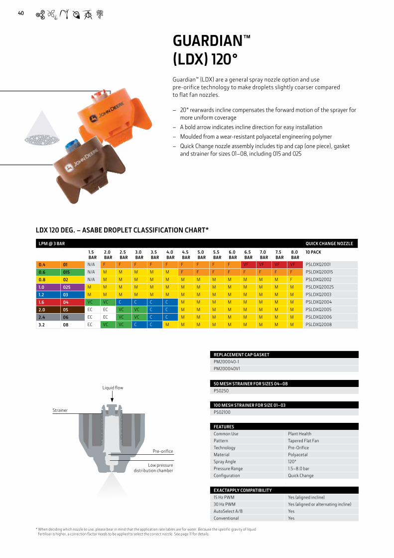
0.4 01 N/A F F F F F F F F F VF VF VF VF PSLDXQ2001
0.6 015 N/A M M M M M F F F F F F F F PSLDXQ20015
0.8 02 N/A M M M M M M M M M M M M F PSLDXQ2002
1.0 025 M M M M M M M M M M M M M M PSLDXQ20025
1.2 03 M M M M M M M M M M M M M M PSLDXQ2003
1.6 04 VC VC C C C C M M M M M M M M PSLDXQ2004
2.0 05 EC EC VC VC C C M M M M M M M M PSLDXQ2005
2.4 06 EC EC VC VC C C M M M M M M M M PSLDXQ2006
3.2 08 EC VC VC C C M M M M M M M M M PSLDXQ2008
GUARDIAN™ (LDX) 120°Guardian™ (LDX) are a general spray nozzle option and use pre-orifice technology to make droplets slightly coarser compared to flat fan nozzles.
– 20° rearwards incline compensates the forward motion of the sprayer for more uniform coverage
– A bold arrow indicates incline direction for easy installation – Moulded from a wear-resistant polyacetal engineering polymer – Quick Change nozzle assembly includes tip and cap (one piece), gasket
and strainer for sizes 01–08, including 015 and 025
LDX 120 DEG. – ASABE DROPLET CLASSIFICATION CHART*
FEATURESCommon Use Plant HealthPattern Tapered Flat FanTechnology Pre-OrificeMaterial PolyacetalSpray Angle 120°Pressure Range 1.5–8.0 barConfiguration Quick Change
EXACTAPPLY COMPATIBILITY15 Hz PWM Yes (aligned incline)30 Hz PWM Yes (aligned or alternating incline)AutoSelect A/B YesConventional Yes
50 MESH STRAINER FOR SIZES 04–08PS0250
100 MESH STRAINER FOR SIZE 01–03PS02100
REPLACEMENT CAP GASKETPM200040-1PM200040V1
* When deciding which nozzle to use, please bear in mind that the application rate tables are for water. Because the specific gravity of liquid fertiliser is higher, a correction factor needs to be applied to select the correct nozzle. See page 11 for details.
Liquid flow
Strainer
Pre-orifice
Low pressure distribution chamber
40

41
GUARDIAN APPLICATION CHART – 50CM NOZZLE SPACING
TIP SIZE ASABE DROPLET SIZE
PRESSURE (BAR)
FLOW RATE (LPM)
APPLICATION RATE L/HA – 50 CM SPACING KM/H
3 4 6 7 8 10 12 15 20 25 30
01
N/A 1.5 0.283 113 85 57 48 42 34 28 23 17 14 11F 2 0.327 131 98 65 56 49 39 33 26 20 16 13F 3 0.400 160 120 80 69 60 48 40 32 24 19 16F 4 0.462 185 139 92 79 69 55 46 37 28 22 18F 5 0.516 207 155 103 89 77 62 52 41 31 25 21F 6 0.566 226 170 113 97 85 68 57 45 34 27 23VF 7 0.611 244 183 122 105 92 73 61 49 37 29 24VF 8 0.653 261 196 131 112 98 78 65 52 39 31 26
015
N/A 1.5 0.424 170 127 85 73 64 51 42 34 25 20 17M 2 0.490 196 147 98 84 73 59 49 39 29 24 20M 3 0.600 240 180 120 103 90 72 60 48 36 29 24M 4 0.693 277 208 139 119 104 83 69 55 42 33 28F 5 0.775 310 232 155 133 116 93 77 62 46 37 31F 6 0.849 339 255 170 145 127 102 85 68 51 41 34F 7 0.917 367 275 183 157 137 110 92 73 55 44 37F 8 0.980 392 294 196 168 147 118 98 78 59 47 39
02
N/A 1.5 0.566 226 170 113 97 85 68 57 45 34 27 23M 2 0.653 261 196 131 112 98 78 65 52 39 31 26M 3 0.800 320 240 160 137 120 96 80 64 48 38 32M 4 0.924 370 277 185 158 139 111 92 74 55 44 37M 5 1.033 413 310 207 177 155 124 103 83 62 50 41M 6 1.131 453 339 226 194 170 136 113 91 68 54 45M 7 1.222 489 367 244 209 183 147 122 98 73 59 49F 8 1.306 523 392 261 224 196 157 131 105 78 63 52
025
M 1.5 0.707 283 212 141 121 106 85 71 57 42 34 28M 2 0.816 327 245 163 140 122 98 82 65 49 39 33M 3 1.000 400 300 200 171 150 120 100 80 60 48 40M 4 1.155 462 346 231 198 173 139 115 92 69 55 46M 5 1.291 516 387 258 221 194 155 129 103 77 62 52M 6 1.414 566 424 283 242 212 170 141 113 85 68 57M 7 1.528 611 458 306 262 229 183 153 122 92 73 61M 8 1.633 653 490 327 280 245 196 163 131 98 78 65
03
C 1.5 0.849 339 255 170 145 127 102 85 68 51 41 34M 2 0.980 392 294 196 168 147 118 98 78 59 47 39M 3 1.200 480 360 240 206 180 144 120 96 72 58 48M 4 1.386 554 416 277 238 208 166 139 111 83 67 55M 5 1.549 620 465 310 266 232 186 155 124 93 74 62M 6 1.697 679 509 339 291 255 204 170 136 102 81 68M 7 1.833 733 550 367 314 275 220 183 147 110 88 73M 8 1.960 784 588 392 336 294 235 196 157 118 94 78
04
VC 1.5 1.131 453 339 226 194 170 136 113 91 68 54 45VC 2 1.306 523 392 261 224 196 157 131 105 78 63 52C 3 1.600 640 480 320 274 240 192 160 128 96 77 64C 4 1.848 739 554 370 317 277 222 185 148 111 89 74M 5 2.066 826 620 413 354 310 248 207 165 124 99 83M 6 2.263 905 679 453 388 339 272 226 181 136 109 91M 7 2.444 978 733 489 419 367 293 244 196 147 117 98M 8 2.613 1,045 784 523 448 392 314 261 209 157 125 105
05
EC 1.5 1.414 566 424 283 242 212 170 141 113 85 68 57EC 2 1.633 653 490 327 280 245 196 163 131 98 78 65VC 3 2.000 800 600 400 343 300 240 200 160 120 96 80C 4 2.309 924 693 462 396 346 277 231 185 139 111 92M 5 2.582 1,033 775 516 443 387 310 258 207 155 124 103M 6 2.828 1,131 849 566 485 424 339 283 226 170 136 113M 7 3.055 1,222 917 611 524 458 367 306 244 183 147 122F 8 3.266 1,306 980 653 560 490 392 327 261 196 157 131
06
EC 1.5 1.697 679 509 339 291 255 204 170 136 102 81 68EC 2 1.960 784 588 392 336 294 235 196 157 118 94 78VC 3 2.400 960 720 480 411 360 288 240 192 144 115 96C 4 2.771 1,109 831 554 475 416 333 277 222 166 133 111M 5 3.098 1,239 930 620 531 465 372 310 248 186 149 124M 6 3.394 1,358 1,018 679 582 509 407 339 272 204 163 136M 7 3.666 1,466 1,100 733 628 550 440 367 293 220 176 147M 8 3.919 1,568 1,176 784 672 588 470 392 314 235 188 157
08
EC 1.5 2.263 905 679 453 388 339 272 226 181 136 109 91VC 2 2.613 1,045 784 523 448 392 314 261 209 157 125 105C 3 3.200 1,280 960 640 549 480 384 320 256 192 154 128M 4 3.695 1,478 1,109 739 633 554 443 370 296 222 177 148M 5 4.131 1,652 1,239 826 708 620 496 413 330 248 198 165M 6 4.525 1,810 1,358 905 776 679 543 453 362 272 217 181F 7 4.888 1,955 1,466 978 838 733 587 489 391 293 235 196F 8 5.226 2,090 1,568 1,045 896 784 627 523 418 314 251 209
Droplet size based on ASABE S572.1 standard. Use at 3 bar for optimum coverage.
41

Liquid flow
Ceramic pre-orifice
Six individual streams for even spray
distribution
Low pressure distribution chamber
S = Six Individual Steams
LPM @ 3 BAR QUICK CHANGE NOZZLE
1.5 BAR 2.0 BAR 2.5 BAR 3.0 BAR 4.0 BAR 10 PACK
0.6 015 S S S S S PSSTCQ10015
0.8 02 S S S S S PSSTCQ1002
1.2 03 S S S S S PSSTCQ1003
1.6 04 S S S S S PSSTCQ1004
2.0 05 S S S S S PSSTCQ1005
2.4 06 S S S S S PSSTCQ1006
3.2 08 S S S S S PSSTCQ1008
4.0 10 S S S S S PSSTCQ1010
6.0 15 S S S S S PSSTCQ1015
FEATURESCommon Use FertiliserPattern StreamsTechnology Pre-OrificeMaterial CeramicSpray Angle 110° EquivalentPressure Range 1.0–4.0 barConfiguration Quick Change
EXACTAPPLY COMPATIBILITY15 Hz PWM No30 Hz PWM NoAutoSelect A/B YesConventional Yes
REPLACEMENT CAP GASKET EPDM (SIZES 015–06)PM200040-1
REPLACEMENT O-RING EPDM (SIZES 08–15)PM65BS205
** When deciding which nozzle to use, please bear in mind that the application rate tables are for water. Because the specific gravity of liquid fertiliser is higher, a correction factor needs to be applied to select the correct nozzle. See page 11 for details.
STRAIGHT STREAM CERAMIC (STC)STC is an optimised solution for applying broadcast liquid fertiliser. It’s six-stream pattern* minimises foliar contact and ensures uniform coverage. The STC’s ceramic metering orifice and low-pressure distribution chamber keep the streams stable, reducing atomisation and helping to prevent leaf burn.
– Compact design provides rapid installation onto standard nozzle bodies – Distributes fertilizer more evenly than a three-stream design – Ceramic metering orifice for a reliably accurate flow distribution – Wear-resistant polyacetal promotes increased durability – Quick change nozzle includes a tip, cap, and gasket (sizes 015–06) or
a one-piece tip/cap and gasket (sizes 08–15)
STC 110 DEG. – ASABE DROPLET CLASSIFICATION CHART**
* This pattern may differ for smaller nozzle sizes
42

TIP SIZE PRESSURE (BAR)
FLOW RATE (LPM)
APPLICATION RATE L/HA – 50 CM SPACING KM/H
3 4 6 7 8 10 12 15 20 25 30
015
1 0.346 139 104 69 59 52 42 35 28 21 17 141.5 0.424 170 127 85 73 64 51 42 34 25 20 172 0.490 196 147 98 84 73 59 49 39 29 24 202.5 0.548 219 164 110 94 82 66 55 44 33 26 223 0.600 240 180 120 103 90 72 60 48 36 29 244 0.693 277 208 139 119 104 83 69 55 42 33 28
02
1 0.462 185 139 92 79 69 55 46 37 28 22 181.5 0.566 226 170 113 97 85 68 57 45 34 27 232 0.653 261 196 131 112 98 78 65 52 39 31 262.5 0.730 292 219 146 125 110 88 73 58 44 35 293 0.800 320 240 160 137 120 96 80 64 48 38 324 0.924 370 277 185 158 139 111 92 74 55 44 37
03
1 0.693 277 208 139 119 104 83 69 55 42 33 281.5 0.849 339 255 170 145 127 102 85 68 51 41 342 0.980 392 294 196 168 147 118 98 78 59 47 392.5 1.095 438 329 219 188 164 131 110 88 66 53 443 1.200 480 360 240 206 180 144 120 96 72 58 484 1.386 554 416 277 238 208 166 139 111 83 67 55
04
1 0.924 370 277 185 158 139 111 92 74 55 44 371.5 1.131 453 339 226 194 170 136 113 91 68 54 452 1.306 523 392 261 224 196 157 131 105 78 63 522.5 1.461 584 438 292 250 219 175 146 117 88 70 583 1.600 640 480 320 274 240 192 160 128 96 77 644 1.848 739 554 370 317 277 222 185 148 111 89 74
05
1 1.155 462 346 231 198 173 139 115 92 69 55 461.5 1.414 566 424 283 242 212 170 141 113 85 68 572 1.633 653 490 327 280 245 196 163 131 98 78 652.5 1.826 730 548 365 313 274 219 183 146 110 88 733 2.000 800 600 400 343 300 240 200 160 120 96 804 2.309 924 693 462 396 346 277 231 185 139 111 92
06
1 1.386 554 416 277 238 208 166 139 111 83 67 551.5 1.697 679 509 339 291 255 204 170 136 102 81 682 1.960 784 588 392 336 294 235 196 157 118 94 782.5 2.191 876 657 438 376 329 263 219 175 131 105 883 2.400 960 720 480 411 360 288 240 192 144 115 964 2.771 1,109 831 554 475 416 333 277 222 166 133 111
08
1 1.848 739 554 370 317 277 222 185 148 111 89 741.5 2.263 905 679 453 388 339 272 226 181 136 109 912 2.613 1,045 784 523 448 392 314 261 209 157 125 1052.5 2.921 1,168 876 584 501 438 351 292 234 175 140 1173 3.200 1,280 960 640 549 480 384 320 256 192 154 1284 3.695 1,478 1,109 739 633 554 443 370 296 222 177 148
10
1 2.309 924 693 462 396 346 277 231 185 139 111 921.5 2.828 1,131 849 566 485 424 339 283 226 170 136 1132 3.266 1,306 980 653 560 490 392 327 261 196 157 1312.5 3.651 1,461 1,095 730 626 548 438 365 292 219 175 1463 4.000 1,600 1,200 800 686 600 480 400 320 240 192 1604 4.619 1,848 1,386 924 792 693 554 462 370 277 222 185
15
1 3.464 1,386 1,039 693 594 520 416 346 277 208 166 1391.5 4.243 1,697 1,273 849 727 636 509 424 339 255 204 1702 4.899 1,960 1,470 980 840 735 588 490 392 294 235 1962.5 5.477 2,191 1,643 1,095 939 822 657 548 438 329 263 2193 6.000 2,400 1,800 1,200 1,029 900 720 600 480 360 288 2404 6.928 2,771 2,078 1,386 1,188 1,039 831 693 554 416 333 277
STRAIGHT STREAM CERAMIC APPLICATION CHART – 50CM NOZZLE SPACING
ASABE droplet size based on ASABE S572.1 standard. Use at 3 bar for optimum coverage.
43
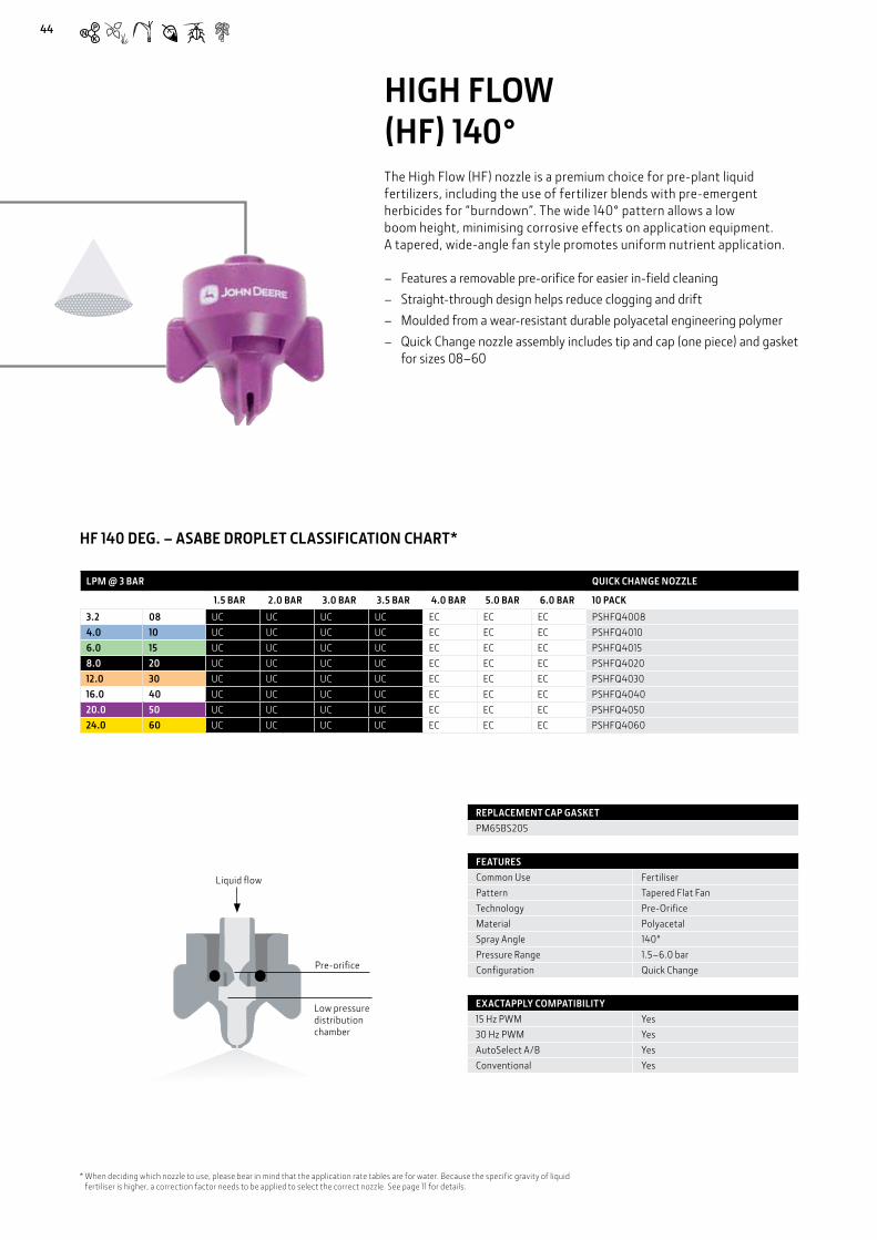
44
HIGH FLOW (HF) 140°The High Flow (HF) nozzle is a premium choice for pre-plant liquid fertilizers, including the use of fertilizer blends with pre-emergent herbicides for “burndown”. The wide 140° pattern allows a low boom height, minimising corrosive effects on application equipment. A tapered, wide-angle fan style promotes uniform nutrient application.
– Features a removable pre-orifice for easier in-field cleaning – Straight-through design helps reduce clogging and drift – Moulded from a wear-resistant durable polyacetal engineering polymer – Quick Change nozzle assembly includes tip and cap (one piece) and gasket
for sizes 08–60
LPM @ 3 BAR QUICK CHANGE NOZZLE
1.5 BAR 2.0 BAR 3.0 BAR 3.5 BAR 4.0 BAR 5.0 BAR 6.0 BAR 10 PACK
3.2 08 UC UC UC UC EC EC EC PSHFQ40084.0 10 UC UC UC UC EC EC EC PSHFQ40106.0 15 UC UC UC UC EC EC EC PSHFQ40158.0 20 UC UC UC UC EC EC EC PSHFQ402012.0 30 UC UC UC UC EC EC EC PSHFQ403016.0 40 UC UC UC UC EC EC EC PSHFQ404020.0 50 UC UC UC UC EC EC EC PSHFQ405024.0 60 UC UC UC UC EC EC EC PSHFQ4060
HF 140 DEG. – ASABE DROPLET CLASSIFICATION CHART*
FEATURESCommon Use FertiliserPattern Tapered Flat FanTechnology Pre-OrificeMaterial PolyacetalSpray Angle 140°Pressure Range 1.5–6.0 barConfiguration Quick Change
REPLACEMENT CAP GASKETPM65BS205
EXACTAPPLY COMPATIBILITY15 Hz PWM Yes30 Hz PWM YesAutoSelect A/B YesConventional Yes
* When deciding which nozzle to use, please bear in mind that the application rate tables are for water. Because the specific gravity of liquid fertiliser is higher, a correction factor needs to be applied to select the correct nozzle. See page 11 for details.
Pre-orifice
Low pressure distribution chamber
Liquid flow
44
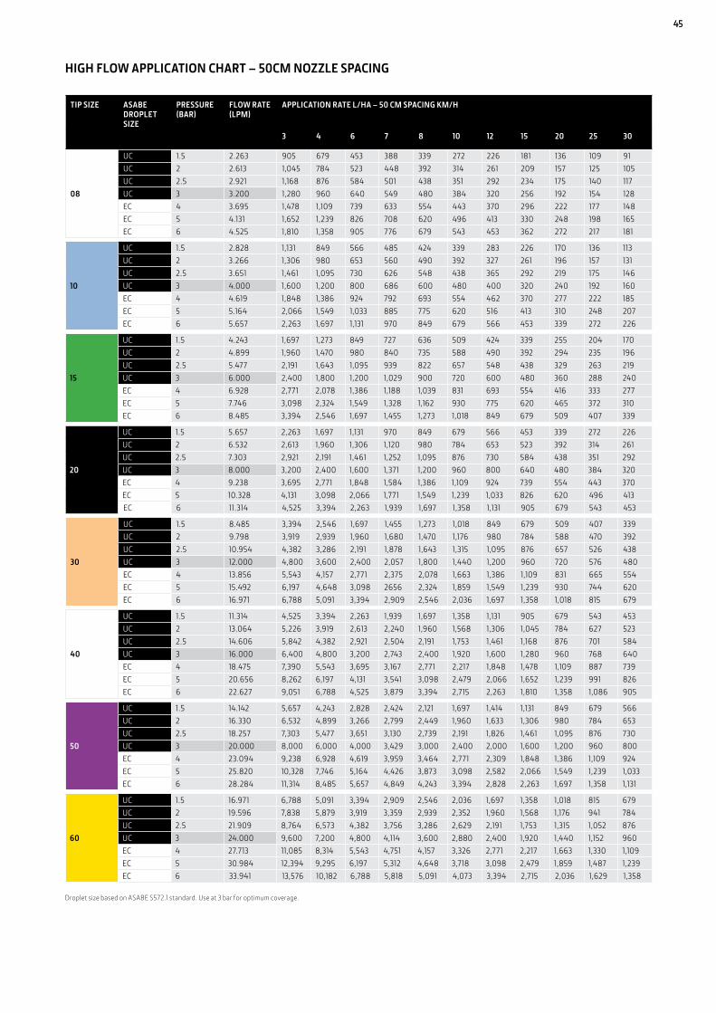
45
HIGH FLOW APPLICATION CHART – 50CM NOZZLE SPACING
Droplet size based on ASABE S572.1 standard. Use at 3 bar for optimum coverage.
TIP SIZE ASABE DROPLET SIZE
PRESSURE (BAR)
FLOW RATE (LPM)
APPLICATION RATE L/HA – 50 CM SPACING KM/H
3 4 6 7 8 10 12 15 20 25 30
08
UC 1.5 2.263 905 679 453 388 339 272 226 181 136 109 91UC 2 2.613 1,045 784 523 448 392 314 261 209 157 125 105UC 2.5 2.921 1,168 876 584 501 438 351 292 234 175 140 117UC 3 3.200 1,280 960 640 549 480 384 320 256 192 154 128EC 4 3.695 1,478 1,109 739 633 554 443 370 296 222 177 148EC 5 4.131 1,652 1,239 826 708 620 496 413 330 248 198 165EC 6 4.525 1,810 1,358 905 776 679 543 453 362 272 217 181
10
UC 1.5 2.828 1,131 849 566 485 424 339 283 226 170 136 113UC 2 3.266 1,306 980 653 560 490 392 327 261 196 157 131UC 2.5 3.651 1,461 1,095 730 626 548 438 365 292 219 175 146UC 3 4.000 1,600 1,200 800 686 600 480 400 320 240 192 160EC 4 4.619 1,848 1,386 924 792 693 554 462 370 277 222 185EC 5 5.164 2,066 1,549 1,033 885 775 620 516 413 310 248 207EC 6 5.657 2,263 1,697 1,131 970 849 679 566 453 339 272 226
15
UC 1.5 4.243 1,697 1,273 849 727 636 509 424 339 255 204 170UC 2 4.899 1,960 1,470 980 840 735 588 490 392 294 235 196UC 2.5 5.477 2,191 1,643 1,095 939 822 657 548 438 329 263 219UC 3 6.000 2,400 1,800 1,200 1,029 900 720 600 480 360 288 240EC 4 6.928 2,771 2,078 1,386 1,188 1,039 831 693 554 416 333 277EC 5 7.746 3,098 2,324 1,549 1,328 1,162 930 775 620 465 372 310EC 6 8.485 3,394 2,546 1,697 1,455 1,273 1,018 849 679 509 407 339
20
UC 1.5 5.657 2,263 1,697 1,131 970 849 679 566 453 339 272 226UC 2 6.532 2,613 1,960 1,306 1,120 980 784 653 523 392 314 261UC 2.5 7.303 2,921 2,191 1,461 1,252 1,095 876 730 584 438 351 292UC 3 8.000 3,200 2,400 1,600 1,371 1,200 960 800 640 480 384 320EC 4 9.238 3,695 2,771 1,848 1,584 1,386 1,109 924 739 554 443 370EC 5 10.328 4,131 3,098 2,066 1,771 1,549 1,239 1,033 826 620 496 413EC 6 11.314 4,525 3,394 2,263 1,939 1,697 1,358 1,131 905 679 543 453
30
UC 1.5 8.485 3,394 2,546 1,697 1,455 1,273 1,018 849 679 509 407 339UC 2 9.798 3,919 2,939 1,960 1,680 1,470 1,176 980 784 588 470 392UC 2.5 10.954 4,382 3,286 2,191 1,878 1,643 1,315 1,095 876 657 526 438UC 3 12.000 4,800 3,600 2,400 2,057 1,800 1,440 1,200 960 720 576 480EC 4 13.856 5,543 4,157 2,771 2,375 2,078 1,663 1,386 1,109 831 665 554EC 5 15.492 6,197 4,648 3,098 2656 2,324 1,859 1,549 1,239 930 744 620EC 6 16.971 6,788 5,091 3,394 2,909 2,546 2,036 1,697 1,358 1,018 815 679
40
UC 1.5 11.314 4,525 3,394 2,263 1,939 1,697 1,358 1,131 905 679 543 453UC 2 13.064 5,226 3,919 2,613 2,240 1,960 1,568 1,306 1,045 784 627 523UC 2.5 14.606 5,842 4,382 2,921 2,504 2,191 1,753 1,461 1,168 876 701 584UC 3 16.000 6,400 4,800 3,200 2,743 2,400 1,920 1,600 1,280 960 768 640EC 4 18.475 7,390 5,543 3,695 3,167 2,771 2,217 1,848 1,478 1,109 887 739EC 5 20.656 8,262 6,197 4,131 3,541 3,098 2,479 2,066 1,652 1,239 991 826EC 6 22.627 9,051 6,788 4,525 3,879 3,394 2,715 2,263 1,810 1,358 1,086 905
50
UC 1.5 14.142 5,657 4,243 2,828 2,424 2,121 1,697 1,414 1,131 849 679 566UC 2 16.330 6,532 4,899 3,266 2,799 2,449 1,960 1,633 1,306 980 784 653UC 2.5 18.257 7,303 5,477 3,651 3,130 2,739 2,191 1,826 1,461 1,095 876 730UC 3 20.000 8,000 6,000 4,000 3,429 3,000 2,400 2,000 1,600 1,200 960 800EC 4 23.094 9,238 6,928 4,619 3,959 3,464 2,771 2,309 1,848 1,386 1,109 924EC 5 25.820 10,328 7,746 5,164 4,426 3,873 3,098 2,582 2,066 1,549 1,239 1,033EC 6 28.284 11,314 8,485 5,657 4,849 4,243 3,394 2,828 2,263 1,697 1,358 1,131
60
UC 1.5 16.971 6,788 5,091 3,394 2,909 2,546 2,036 1,697 1,358 1,018 815 679UC 2 19.596 7,838 5,879 3,919 3,359 2,939 2,352 1,960 1,568 1,176 941 784UC 2.5 21.909 8,764 6,573 4,382 3,756 3,286 2,629 2,191 1,753 1,315 1,052 876UC 3 24.000 9,600 7,200 4,800 4,114 3,600 2,880 2,400 1,920 1,440 1,152 960EC 4 27.713 11,085 8,314 5,543 4,751 4,157 3,326 2,771 2,217 1,663 1,330 1,109EC 5 30.984 12,394 9,295 6,197 5,312 4,648 3,718 3,098 2,479 1,859 1,487 1,239EC 6 33.941 13,576 10,182 6,788 5,818 5,091 4,073 3,394 2,715 2,036 1,629 1,358
45

46
EXTENSION CAPS FOR INCLINE NOZZLES
For certain boom positions or when a lower nozzle position is required, Extension Caps are now available for improving the spray efficiency for nozzles with angled forward/backward inclines such as 3D nozzles.
BROADCAST NOZZLES INDEXFind what you need quickly and easily and make your list.
QUICK CHANGE NOZZLE
MESH STRAINER
REPLACEMENT CAP GASKET
10 PACK 10 PACK 40 PACK
W/ STRAINER
PS3DQ00015
PS311 (100 mesh strainer) EPDM
– PM200040-1Viton – PM200040V1
PS3DQ0002PS3DQ00025PS3DQ0003PS3DQ00035PS3DQ0004
PS310 (50 mesh strainer)
PS3DQ0005PS3DQ0006PS3DQ0008
3D NOZZLE
3D Nozzle
Low-Drift Max (LDM) 120°
LOW-DRIFT MAX (LDM) 120°
QUICK CHANGE NOZZLE
REPLACEMENT CAP GASKET
10 PACK 40 PACK
W/ STRAINERPSLDMQ2003
EPDM – PM200040-1Viton – PM200040V1
PSLDMQ2004 PSLDMQ2005 PSLDMQ2006PSLDMQ2008PSLDMQ2010
Low-Drift Twin (LDT) 110°
LOW-DRIFT TWIN (LDT) 110°
QUICK CHANGE NOZZLE
REPLACEMENT CAP GASKET
10 PACK 40 PACK
W/ STRAINERPSLDTQ1003
EPDM – PM200040-1Viton – PM200040V1
PSLDTQ1004PSLDTQ1005PSLDTQ1006PSLDTQ1008PSLDTQ1010PSLDTQ1012PSLDTQ1016
46

47
Ultra Low-drift (ULD) 120°
QUICK CHANGE NOZZLE
SPRAY TIPS CAPS 50 MESH STRAINERS
REPLACEMENT CAP GASKET (WITH STRAINER)
REPLACEMENT CAP GASKET (WITHOUT STRAINER)
10 PACK 10 PACK 10 PACK 10 PACK 40 PACK 10 PACK
W/ STRAINER
PSULDQ20015 PSULD20015 PS900015
PS310 PS17000255
EPDM – PM200040-1Viton – PM200040V1
PSULDQ2002 PSULD2002 PS90002
PSULDQ20025 PSULD20025 PS900025
PSULDQ2003 PSULD2003 PS90003
PSULDQ2004 PSULD2004 PS90004
PSULDQ2005 PSULD2005 PS90005
PSULDQ2006 PSULD2006 PS90006
PSULDQ2008 PSULD2008 PS90008
ULTRA LOW-DRIFT (ULD) 120°
GuardianAIR Twin™ (GAT) 110°
QUICK CHANGE NOZZLE
50 MESH STRAINER
REPLACEMENT CAP GASKET
10 PACK 10 PACK 10 PACK
W/ STRAINER
PSGAT1002
PS0250 PM65BS205
PSGAT10025PSGAT1003PSGAT10035PSGAT1004PSGAT1005PSGAT1006PSGAT1008
GUARDIANAIR TWIN™ (GAT) 110°
Ultra Low-Drift Max (ULDM) 130°
QUICK CHANGE NOZZLE
50 MESH STRAINER
REPLACEMENT CAP GASKET
10 PACK 10 PACK 40 PACK
W/ STRAINERPSULDMQ30025
PS0250 for all sizes
EPDM – PM200040-1Viton – PM200040V1
PSULDMQ3003PSULDMQ3004PSULDMQ3005PSULDMQ3006PSULDMQ3008
ULTRA LOW-DRIFT MAX (ULDM) 130°
47

Extended Range Ceramic (ERC) 110°
QUICK CHANGE NOZZLE
REPLACEMENT CAP GASKET
10 PACK 40 PACKPSERCQ10015
EPDM – PM200040-1Viton – PM200040V1
PSERCQ1002PSERCQ1003PSERCQ1004PSERCQ1005PSERCQ1006
EXTENDED RANGE CERAMIC (ERC) 110°
Guardian™ (LDX) 120°
GUARDIAN™ (LDX) 120°
QUICK CHANGE NOZZLE
50 MESH STRAINER
100 MESH STRAINER
REPLACEMENT CAP GASKET
10 PACK 10 PACK 10 PACK 40 PACKPSLDXQ2001
PS02100
EPDM – PM200040-1Viton – PM200040V1
PSLDXQ20015PSLDXQ2002PSLDXQ20025PSLDXQ2003PSLDXQ2004
PS0250PSLDXQ2005PSLDXQ2006PSLDXQ2008
Extended Range (ER) 110°
QUICK CHANGE NOZZLE
REPLACEMENT CAP GASKET
10 PACK 10 PACKPSERQ10015
EPDM – PM200040-1Viton – PM200040V1
PSERQ1002PSERQ10025PSERQ1003PSERQ1004PSERQ1005PSERQ1006PSERQ1008PSERQ1010PSERQ1015
EXTENDED RANGE (ER) 110°
Low-drift Air (LDA) 110°
QUICK CHANGE NOZZLE
SPRAY TIPS CAPS REPLACEMENT CAP GASKET
10 PACK 10 PACK 10 PACK 40 PACKPSLDAQ10015 PSLDA10015 PS900015
EPDM – PM200040-1Viton – PM200040V1
PSLDAQ1002 PSLDA1002 PS90002PSLDAQ10025 PSLDA10025 PS900025
PSLDAQ1003 PSLDA1003 PS90003PSLDAQ10035 PSLDA10035 PS900035PSLDAQ1004 PSLDA1004 PS90004PSLDAQ1005 PSLDA1005 PS90005
LOW-DRIFT AIR (LDA) 110°
48

High Flow (HF) 140°
QUICK CHANGE NOZZLE
REPLACEMENT CAP GASKET
10 PACK 40 PACKPSHFQ4008
PM65BS205
PSHFQ4010PSHFQ4015PSHFQ4020PSHFQ4030PSHFQ4040PSHFQ4050PSHFQ4060
HIGH FLOW (HF) 140°
Straight Stream Ceramic (STC)
QUICK CHANGE NOZZLE
REPLACEMENT
10 PACK 10 PACKPSSTCQ10015
Cap Gasket EPDM – PM200040-1Cap Gasket Viton – PM200040V1
PSSTCQ1002PSSTCQ1003PSSTCQ1004PSSTCQ1005PSSTCQ1006PSSTCQ1008
O-Ring EPDM – PM65BS205PSSTCQ1010PSSTCQ1015
STRAIGHT STREAM CERAMIC (STC)
49
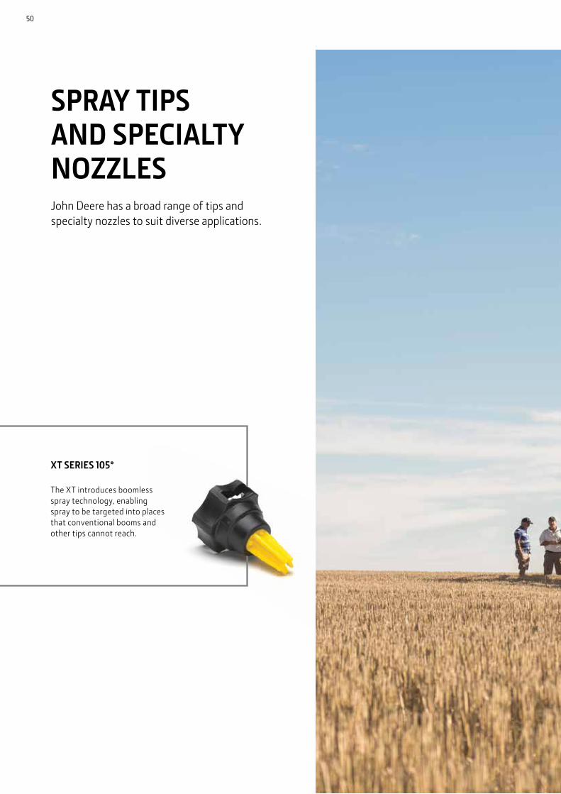
XT SERIES 105°
The XT introduces boomless spray technology, enabling spray to be targeted into places that conventional booms and other tips cannot reach.
SPRAY TIPS AND SPECIALTY NOZZLESJohn Deere has a broad range of tips and specialty nozzles to suit diverse applications.
50

51

+/- 18˚
15˚
95˚
TYPICAL SPRAY PATTERN PRODUCED BY XT SERIES
ADJUSTABLE SWATH WIDTHSwath width can be increased or decreased by adjusting the angle of the tip +/- 18 .̊
COMMON USES OF THE BOOM X TENDER SPRAY NOZZLES
Boom X Tender Spraying (last tip on the boom)
Boomless Spraying
Boomless Spraying with Centre Nozzle
BOOMLESS FLAT FAN NOZZLES – FENCE ROW/BOOMLESS (XT)The XT introduces boomless spray technology, enabling spray to be targeted into places that conventional booms and other tips cannot reach. XT delivers a uniform spray pattern over a distance of up to 4.9 metres. Ideal for weed control in forests and pasture land.
– Ideal for applications where a conventional boom cannot be used due to obstacles
– Common uses include orchard, vineyard, forestry, pasture, turf and golf course spraying, as well as maintaining rights-of-way and fence rows
– Excellent Low-drift option while extending spray reach – Large droplet size reduces spray drift and promotes spray penetration – Maintains a consistent spray swath over a pressure range of 2.0-4.0 BAR – Standard models with precision-molded polyacetal tip and threaded
stainless steel body provide excellent durability and low maintenance
52

FEATURES
Common Use Weeds
Pattern Boomless Fan
Technology Pre-Orifice
Material Stainless or Polyacetal
Spray Angle 105º
Pressure Range 2.0-4.0 BAR
Configuration Stainless, Quick Change
STAINLESS REPLACEMENT TIP KITS - INCLUDES GASKET, STAINLESS STEEL INSERT & POLYACETAL PATTERN GENERATOR
PSXTIQ10KIT
PSXTIQ20KIT
PSXTIQ24KIT
METRICS
TIP SIZE PRESSURE (BAR)
FLOW RATE (LPM)
APPLICATION RATE L/HA – 50 CM SPACING KM/H
SWATH WIDTH (M) AT 2.76 BAR 1.22 METRES HIGH
QUICK CHANGE POLYACETOL
STAINLESS STEEL
4 5 6 7 8 10 12 14 16 18 20
10 (1/4 in.)2 3.2 124 99 83 71 62 50 41 35 31 28 25
3.9 PSXTIQ103 3.9 152 121 101 87 76 61 51 43 38 34 30
4 4.6 175 140 117 100 88 70 58 50 44 39 35
20 (1/4 in.)2 6.4 201 161 134 115 101 81 67 58 50 45 40
4.8 PSXTQ20 PSXTIQ203 7.9 247 197 165 141 123 99 82 71 62 55 49
4 9.1 285 228 190 163 142 114 95 81 71 63 57
24 (1/4 in.)2 7.7 237 189 158 135 118 95 79 68 59 53 47
4.9 PSXTQ24 PSXTIQ243 9.5 290 232 193 166 145 116 97 83 73 64 58
4 10.9 335 268 223 191 167 134 112 96 84 74 67
43 (3/8 in.)2 13.9 473 378 315 270 236 189 158 135 118 105 95
4.4 PSXTQ433 17 579 463 386 331 289 232 193 165 145 129 116
4 19.6 668 535 446 382 334 267 223 191 167 149 134
53
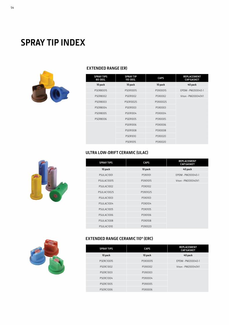
SPRAY TIPS CAPS REPLACEMENT CAP GASKET
10 pack 10 pack 40 pack
PSULAC1001 PS90101 EPDM - PM200040-1
PSULAC10015 PS901015 Viton - PM200040V1
PSULAC1002 PS90102
PSULAC10025 PS901025
PSULAC1003 PS90103
PSULAC1004 PS90104
PSULAC1005 PS90105
PSULAC1006 PS90106
PSULAC1008 PS90108
PSULAC1010 PS90020
SPRAY TIPS CAPS REPLACEMENT CAP GASKET
10 pack 10 pack 40 pack
PSERC10015 PS900015 EPDM - PM200040-1
PSERC1002 PS90002 Viton - PM200040V1
PSERC1003 PS90003
PSERC1004 PS90004
PSERC1005 PS90005
PSERC1006 PS90006
SPRAY TIPS 80-DEG.
SPRAY TIP 110-DEG. CAPS REPLACEMENT
CAP GASKET
10 pack 10 pack 10 pack 40 pack
PSER80015 PSER10015 PS900015 EPDM - PM200040-1
PSER8002 PSER1002 PS90002 Viton - PM200040V1
PSER8003 PSER10025 PS900025
PSER8004 PSER1003 PS90003
PSER8005 PSER1004 PS90004
PSER8006 PSER1005 PS90005
PSER1006 PS90006
PSER1008 PS90008
PSER1010 PS90020
PSER1015 PS90020
EXTENDED RANGE CERAMIC 110º (ERC)
EXTENDED RANGE (ER)
SPRAY TIP INDEX
ULTRA LOW-DRIFT CERAMIC (ULAC)
54
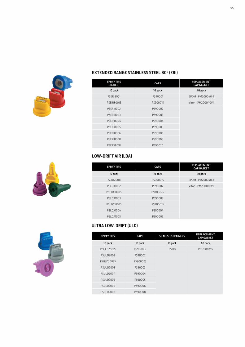
SPRAY TIPS80-DEG. CAPS REPLACEMENT
CAP GASKET
10 pack 10 pack 40 pack
PSERI8001 PS90001 EPDM - PM200040-1
PSERI80015 PS900015 Viton - PM200040V1
PSERI8002 PS90002
PSERI8003 PS90003
PSERI8004 PS90004
PSERI8005 PS90005
PSERI8006 PS90006
PSERI8008 PS90008
PSERS8010 PS90020
SPRAY TIPS CAPS REPLACEMENT CAP GASKET
10 pack 10 pack 40 pack
PSLDA10015 PS900015 EPDM - PM200040-1
PSLDA1002 PS90002 Viton - PM200040V1
PSLDA10025 PS900025
PSLDA1003 PS90003
PSLDA10035 PS900035
PSLDA1004 PS90004
PSLDA1005 PS90005
SPRAY TIPS CAPS 50 MESH STRAINERS REPLACEMENT CAP GASKET
10 pack 10 pack 10 pack 40 pack
PSULD20015 PS900015 PS310 PS17000255
PSULD2002 PS90002
PSULD20025 PS900025
PSULD2003 PS90003
PSULD2004 PS90004
PSULD2005 PS90005
PSULD2006 PS90006
PSULD2008 PS90008
ULTRA LOW-DRIFT (ULD)
EXTENDED RANGE STAINLESS STEEL 80º (ERI)
LOW-DRIFT AIR (LDA)
55

MAKE EVERY DROP COUNT.Your John Deere dealer is a nozzle expert. You can rely on them to help you choose the right nozzles to maximise your spraying operation’s performance.
JohnDeere.com.auJohnDeere.co.nz
CP8123 09/19 REPRINT
This literature has been compiled for worldwide circulation. While general information, pictures and descriptions are provided, some illustrations and text may include finance, credit, insurance, product options and accessories NOT AVAILABLE in all countries or regions. In some countries, products and accessories may require modifications or additions to ensure compliance with the local regulations of those countries. PLEASE CONTACT YOUR LOCAL DEALER FOR DETAILS. John Deere reserves the right to change specification and design of all products described in this literature without notice. John Deere’s green and yellow colour scheme, the leaping deer symbol, and JOHN DEERE are trademarks of Deere & Company. All photography and illustrations contained herein are copyrighted assets of Deere & Company.