Embed Size (px)
Citation preview

1
John Deere R4030/R4038 Sprayer/Dry BoxLubrication System Installation Guide

2
ContentsPages
Preparation/Installation Overview 3Introduction 4Purging Instruction 5Divider Valve Operation 6Components Glossary 7-8John Deere R4030/R4038 Sprayer Layout Drawing 9 Bill of Materials 10Lubrication Point Overview 11-12Pump Installation Detail 13-14Primary Valve Detail 15-16LH Front Chassis Secondary Valve Detail 17-22 RH Front Chassis Secondary Valve Detail 23-24 Rear Chassis Secondary Valve Detail 25-27 Boom Lift Secondary Valve Detail 28-34 System Primary to Dry Box Primary Routing 35 Dry Box Primary Valve Detail 36-41 Dry Box Secondary Valve Detail 42-44 Daily Walk-Around Inspection Instructions 45-46Troubleshooting 47Warranty _ 48
3
Preparation/Installation Overview
The following steps will assist the installer with a systematic approach for installing theAutomated lube system on the John Deere R4030/R4038 Sprayer. By following the stepsOutlined, a successful installation will be achieved and will increase the service life of all pins andBearings connected to the lube system.
Preparation
• Compare the bill of material with the kit contents• Clean machine thoroughly• Survey the equipment and locate all lubrication points to be serviced by the lubrication
system• Lubricate each point with a grease gun prior to removing grease fittings to assure grease
acceptance. Any points that will not accept grease must be repaired prior to system installation.
• After confirming all points will accept grease, remove all grease fittings.
Installation Overview
• Install appropriate adapters and tube fittings in lube points.• Position valve mounting brackets on machine.• Attach metering valves to previously mounted brackets.• Using tubing cutters, cut to length individual tubing feed lines from secondary valves to lube
points and make connections.• When installing feed line tubing into the Quicklinc fittings, push until firmly seated.• Neatly bundle, loom with spiral wrap provided and tie strap feed lines wherever possible to
protect from abrasion.• Size, cut and attach appropriate hose ends to all supply lines. The high-pressure hose is
used as supply lines from the pump to the primary valve and the primary to the secondary valves. It is recommended that the supply lines be routed and cut only after all valves and the electric pump have been attached to the machine. This assures the supply line is cut to the proper length. Also, allow for unrestricted movement while the machine is in motion.
• Route supply lines from the pump to primary valve and from the primary valve to the secondary valves and make connections.
• Secure supply/feed lines with tie straps, so not in harms way.• Mount pump and make electrical connections (electrical diagram included with the pump).
4
IntroductionThank you for purchasing the Quicklub® On Board Grease System for your John Deere
R4030/R4038 Sprayer. The system has been designed to increase the component life and overall productivity of your equipment, while reducing labor costs related to the traditional method of
point-by-point manual lubrication.
The system consists of the Quicklub® progressive metering valves that positively displace and meter precise amounts up to N.L.G.I. #2 shop grease down to -13°F temperature. Grease is
distributed to each connected point through high-pressure tube and hose.
This Quicklub® kit is designed to work with your John Deere R4030/R4038 Sprayer. This is a fully automated lubrication system utilizing a 24 volt DC heavy duty electric pump with integrated timer that dispenses lubricant to the progressive metering valves at timed intervals. The lubricant
is pumped to the primary metering valve, which distributes it to secondary metering valves in specific zones of service. The secondary metering valves deliver measured amounts of lubricant
proportional to each lube point in its zone.
The components are connected with lengths of high-pressure hose and tubing that are included in the kit. Contents of the kit are specifically marked to coincide with this instruction manual to
achieve a consistent and quality installation.This manual has been included with the system as an easy-to-follow guide for installation and
operation. Keep it with the equipment, as it is also a trouble-shooting manual to keep your automated lubrication system working properly.
This kit also contains Installation and Operation Instructions for the 203 series system supply pump. Please refer to this manual for detailed information on operations, maintenance, trouble shooting and technical data. If missing, please contact Lincoln and request service page form #403439.Durable and reliable, the Quicklub® On Board Grease System has been carefully designed using industry proven products to provide long and trouble-free life under the most
severe farming conditions.
For further information on this system please contact Lincoln Technical Services at 1-314-679-4200 ext. 4782# or fax 1-314-679-4357.
THIS DOCUMENT (INSTALLATION INSTRUCTIONS) IS THE EXCLUSIVE PROPERTY OF LINCOLN INDUSTRIAL CORPORATION (‘LINCOLN’). IT CONTAINS PROPRIETARY DATA
AND INFORMATION DEVELOPED AT LINCOLN’S EXPENSE AND IS FURNISHED UPON THE EXPRESS CONDITION, ACKNOWLEDGED BY THE RECIPIENT, THAT IT’S CONTENTS SHALL NOT BE DISCLOSED, COPIED OR DUPLICATED, DISSEMINATED, OR USED,
EXCEPT FOR THE PURPOSES ESTABLISHED BY WRITTEN CONTRACT OR OTHERWISE AUTHORIZED BY LINCOLN IN WRITING. LINCOLN RESERVES ALL RIGHTS UNDER
PATENT, COPYRIGHT, TRADE SECRET AND OTHER APLICABLE LAWS.® Quicklub is a registered trademark of Lincoln.

5
Cycle Indicator Pin
R2 ValveR3 Valve
PrimaryValve
SecondaryValves
Pump
Hose
Tubing
Lube Point
Prime the system to check for proper operation and leaks. This can be done using the pump or a grease gun:
Grease Gun Method:1. Hook up a grease gun to the grease zerk on the divider block.2. During the pumping process, each valve Cycle Indicator Pin should move in & out indicating grease
flow through the valve. It is recommended to continue to pump through five cycles of the Cycle Indicator Pin. Check for leaks at all fitting connections to ensure the hose & tubing connections are solid.
3. Repeat for each block including the primary.
Manual Lube from pump:1. Fill pump with grease using the grease zerk on the right side of the pump.2. Cycle the pump using the manual lube button on the touch-pad.3. Check to make sure the Cycle Indicator Pin is moving in and out on ALL divider valves4. Check that grease is flowing to each lube point. You should see a grease “donut” at each point.5. Check for leaks at all fitting connections to ensure the hose & tubing connections are solid.6. This process may take multiple manual lube cycles.
Check for leaks at all locations

6
At the heart of every Quicklub System is the metering valve or progressive distributor block, designed to positively meter the input of lubricant (oil up to NLGI #2 greases) out to the connected number of lubrication points irrespective of distance and back pressure. The inlet passageway is connected to all piston chambers at all times with only one piston free to move at any one time.
• With all pistons at the far right, lubricant from the inlet flows against the right end of piston A (fig. 1).
• Lubricant flow shifts piston A from right to left, dispensing piston A output through connecting passages to outlet 2. Piston A shift directs flow against right side of piston B (fig. 2).
• Lubricant flow shifts piston B from right to left, dispensing piston B output through valve ports of piston A and through outlet 7 (fig. 3).
• Lubricant flow shifts piston C from right to left dispensing piston C output through valve ports of piston B and through outlet 5.
• Piston C shift directs lubricant flow against right side of piston D (not illus.)
• Lubricant flow shifts piston D from right to left, dispensing piston D output through valve ports of piston C and through outlet 3.
• Piston D shift directs lubricant through connecting passage to the left side of piston A (fig. 4).
• Lubricant flow against left side of piston A begins the second half cycle which shifts pistons from left to right, dispensing lubricant through outlets 1, 8, 6 and 4 of the divider valve.
Divider Valve Operation
7
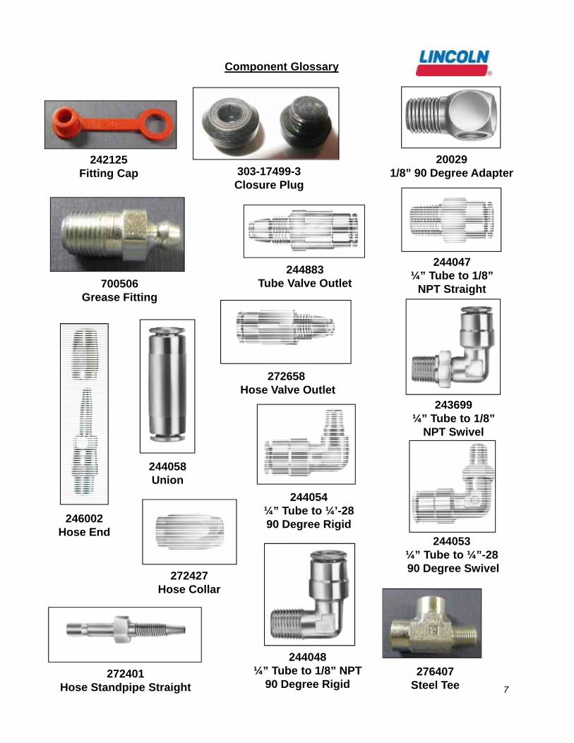
Component Glossary
242125 Fitting Cap
246002 Hose End
303-17499-3 Closure Plug
276407 Steel Tee
700506 Grease Fitting
244053¼” Tube to ¼”-2890 Degree Swivel
244054¼” Tube to ¼’-2890 Degree Rigid
244047¼” Tube to 1/8”
NPT Straight
243699¼” Tube to 1/8”
NPT Swivel
244048¼” Tube to 1/8” NPT
90 Degree Rigid
244058Union
200291/8” 90 Degree Adapter
272427 Hose Collar
244883Tube Valve Outlet
272658Hose Valve Outlet
272401 Hose Standpipe Straight

8
Component Glossary
619-27122-1 Divider Valve (6 Point)
619-26646-2 Divider Valve (8 Point)
619-26645-2 Divider Valve (10 Point)
619-26648-2Divider Valve (12 Point)
270864 PSI Relief Valve
241120 Spiral Wrap
241288 Grease Filled Hose
241054 Nylon Ties
246416 Valve Bracket
51034 & 247023Valve Mounting Nut
& Bolt
270931 P-Clamp ((3/4”)249913 P-Clamp (3/8”

9
John Deere R4030/R4038 Sprayer Lubrication System Layout
12 V
DC
Pow
er
PS
I Relief
Rea
r RH
Lowe
rS
usp
en
sion P
ost
Rig
ht F
ron
t Ch
assisS
econ
dary V
alve61
9-26845-2S
SV
10K
- 10 O
utlet
Stee
ring C
ylinder
He
ad E
nd
Plug
Plu
g
Kin
g P
in U
pper
Kin
g P
in L
ower
Left F
ront C
hassis
Plug
Boo
m Lift (W
et)
Rea
r Chassis
Plug
619-27122-1SSV6K - 6 O
utlet
Prim
ary V
alve
619-26646-2SSV8K - 8 O
utlet
Rea
r Ch
assis S
eco
nd
ary Valve
Pu
mp
940
12
Re
ar LH
Upper
Susp
ension
Po
st
Rig
ht Fro
nt Ch
assis
Re
ar LH
Lower
Susp
ension
Po
st
Fro
nt LH
Upp
erS
uspe
nsion P
ost
Fro
nt LH
Lowe
rS
usp
ension P
ost
Re
ar R
H U
pperS
uspe
nsion P
ost
Fro
nt R
H U
pper
Su
spen
sion Post
Fro
nt R
H Lo
wer
Su
spen
sion Post
Ste
ering
Clynder
Ro
d En
d
Fro
nt Upp
erS
uspe
nsion P
ost
Re
ar U
pper
Susp
ension
Po
st
Fro
nt Low
er
Susp
ension
Po
st
Rea
r Low
erS
uspe
nsion P
ost
Left F
ron
t Ch
assisS
eco
nd
ary V
alve619-2
6845-2S
SV
10K - 10 O
utlet
Stee
ring C
ylinder
He
ad E
nd
Plu
g
Plug
Kin
g Pin U
pper
Kin
g Pin Lo
wer
Ste
ering C
ylinde
rR
od E
nd
Fro
nt Up
per
Susp
ensio
n Post
Re
ar U
pper
Su
spen
sion P
ost
Fro
nt Low
erS
usp
ension P
ost
Rea
r Low
erS
uspe
nsion P
ost Left C
onveyor
Idler S
haft
Left C
onveyor
Dra
gshaft
619-26648-2SSV12K - 12 O
utlet
Dry
Bo
x P
rima
ry
Rig
ht C
onveyor
Idler S
haft
Left M
ultip
lier
Idler Sha
ft
Rig
ht Mu
ltiplierD
ragsha
ft
Left C
onve
yor
Snu
bbe
r Pulley
Plug
Rig
ht Multiplie
rIdler S
haft
Rig
ht C
onve
yorD
ragsha
ft
Left M
ultip
lierD
ragsh
aft
Dry B
ox S
econdary
Sp
inne
r Jack
Spin
ne
r Tube
Sp
inn
er Jack
619-27122-1SSV6K - 6 O
utlet
Dry B
ox S
econ
dary
Spin
ne
r Tube
Rear R
H B
oom
LiftA
rm P
ivot Up
per
Rea
r RH
Boom
Lift
Arm
Pivo
t Ce
nter
Rear R
H B
oom
LiftA
rm P
ivot L
ower
Rear LH
Boo
m Lift
Arm
Pivo
t Upp
er
Re
ar LH B
oom
LiftA
rm P
ivot C
enter
Rea
r LH
Boo
m Lift
Arm
Pivo
t Low
er
Fro
nt R
H B
oom Lift
Arm
Pivot U
pper
Fro
nt R
H B
oom
LiftA
rm P
ivot Center
Fro
nt R
H B
oom
LiftA
rm P
ivot Low
er
Fro
nt L
H B
oom
Lift
Arm
Pivot U
ppe
r
Fro
nt LH
Boom
LiftA
rm P
ivot Center
Fro
nt L
H B
oom
Lift
Arm
Pivot L
owe
r
619-26648-2SSV12K - 12 O
utlet
Bo
om
Lift S
econ
dary V
alve
Dry P
rimary (D
ry)
Plu
gP
lug
Rig
ht C
onveyor
Sn
ubb
er Pulley

10
Bill of Material
Part # Desc Qty
Pump/Acc94012 Pump 1278667 Bracket 1Valves/Acc619-27122-1 SSV 6 2619-26648-2 SSV 12 2619-26646-2 SSV 8 1619-26845-2 SSV 10 2242125 Zerk Cap 6700506 High Pressure Zerk 6246416 Valve Bracket 651304 Valve Mounting Nut 12247023 Valve Mounting Bolt 10276407 1/8" Tee 6244883 Tube Valve Outlet 52272658 Hose Valve Outlet 5303-17499-3 Valve Plug 13Hose/Fittings241288 Hose 40' 1.51246002 1/8" Swivel Hose Fitting 11272427 Hose collar 5272401 Hose Standpipe Straight 5Tube/Fit270784 Zerk-Lock Adapter 2274048 Grease Filled Tubing 8244053 1/4" tube to 1/4"-28 90 Swivel 24244054 1/4" tube to 1/4"-28 90 Rigid 4244055 1/4" tube to 1/4"-28 90 Straight 2243699 1/4" tube to 1/8" NPT 90 swivel 4244048 1/4" tube to 1/8" NPT 90 Rigid 12244047 1/4" tube to 1/8" NPT straight 6241110 Spiral Wrap 10' 15241054 Zip Ties (100) 420031 1/8" 90 deg Adptr 220029 1/8" 90 deg Adptr 313154 Adaptor 2Couplers272356 Coupler 1272357 Nipple 2272358 Couple Plug 1272359 Nipple Cap 2
11
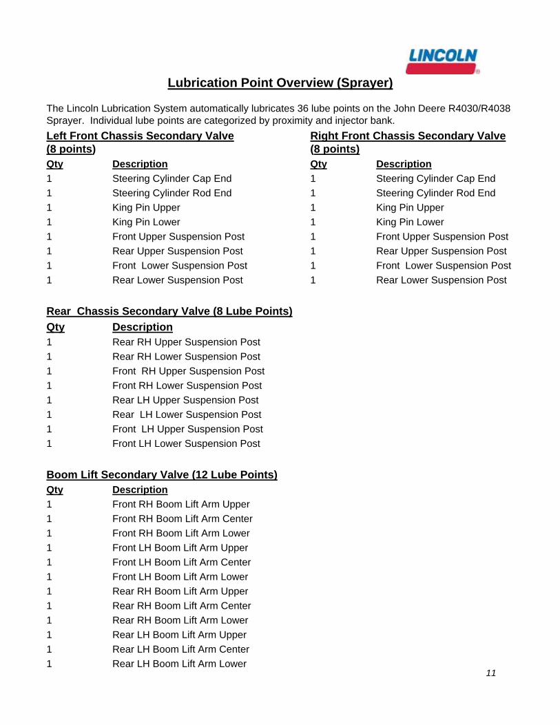
The Lincoln Lubrication System automatically lubricates 36 lube points on the John Deere R4030/R4038 Sprayer. Individual lube points are categorized by proximity and injector bank.
Left Front Chassis Secondary Valve Right Front Chassis Secondary Valve (8 points) (8 points)Qty Description Qty Description
1 Steering Cylinder Cap End 1 Steering Cylinder Cap End
1 Steering Cylinder Rod End 1 Steering Cylinder Rod End
1 King Pin Upper 1 King Pin Upper
1 King Pin Lower 1 King Pin Lower
1 Front Upper Suspension Post 1 Front Upper Suspension Post
1 Rear Upper Suspension Post 1 Rear Upper Suspension Post
1 Front Lower Suspension Post 1 Front Lower Suspension Post
1 Rear Lower Suspension Post 1 Rear Lower Suspension Post
Rear Chassis Secondary Valve (8 Lube Points)
Qty Description1 Rear RH Upper Suspension Post
1 Rear RH Lower Suspension Post
1 Front RH Upper Suspension Post
1 Front RH Lower Suspension Post
1 Rear LH Upper Suspension Post
1 Rear LH Lower Suspension Post
1 Front LH Upper Suspension Post
1 Front LH Lower Suspension Post
Boom Lift Secondary Valve (12 Lube Points)Qty Description
1 Front RH Boom Lift Arm Upper
1 Front RH Boom Lift Arm Center
1 Front RH Boom Lift Arm Lower
1 Front LH Boom Lift Arm Upper
1 Front LH Boom Lift Arm Center
1 Front LH Boom Lift Arm Lower
1 Rear RH Boom Lift Arm Upper
1 Rear RH Boom Lift Arm Center
1 Rear RH Boom Lift Arm Lower
1 Rear LH Boom Lift Arm Upper
1 Rear LH Boom Lift Arm Center
1 Rear LH Boom Lift Arm Lower
Lubrication Point Overview (Sprayer)
12
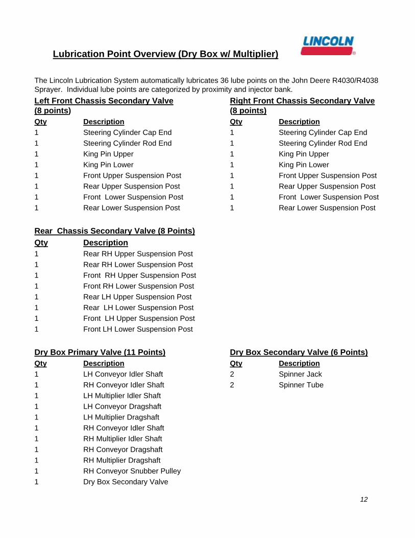
The Lincoln Lubrication System automatically lubricates 36 lube points on the John Deere R4030/R4038 Sprayer. Individual lube points are categorized by proximity and injector bank.
Left Front Chassis Secondary Valve Right Front Chassis Secondary Valve (8 points) (8 points)Qty Description Qty Description
1 Steering Cylinder Cap End 1 Steering Cylinder Cap End
1 Steering Cylinder Rod End 1 Steering Cylinder Rod End
1 King Pin Upper 1 King Pin Upper
1 King Pin Lower 1 King Pin Lower
1 Front Upper Suspension Post 1 Front Upper Suspension Post
1 Rear Upper Suspension Post 1 Rear Upper Suspension Post
1 Front Lower Suspension Post 1 Front Lower Suspension Post
1 Rear Lower Suspension Post 1 Rear Lower Suspension Post
Rear Chassis Secondary Valve (8 Points)
Qty Description1 Rear RH Upper Suspension Post
1 Rear RH Lower Suspension Post
1 Front RH Upper Suspension Post
1 Front RH Lower Suspension Post
1 Rear LH Upper Suspension Post
1 Rear LH Lower Suspension Post
1 Front LH Upper Suspension Post
1 Front LH Lower Suspension Post
Dry Box Primary Valve (11 Points) Dry Box Secondary Valve (6 Points)Qty Description Qty Description
1 LH Conveyor Idler Shaft 2 Spinner Jack
1 RH Conveyor Idler Shaft 2 Spinner Tube
1 LH Multiplier Idler Shaft
1 LH Conveyor Dragshaft
1 LH Multiplier Dragshaft
1 RH Conveyor Idler Shaft
1 RH Multiplier Idler Shaft
1 RH Conveyor Dragshaft
1 RH Multiplier Dragshaft
1 RH Conveyor Snubber Pulley
1 Dry Box Secondary Valve
Lubrication Point Overview (Dry Box w/ Multiplier)

13
Pump Settings:
Set pump “OFF” time at 60 minutes and pump “ON” time at 4 minutes for “normal” utility operation.
P203 pump to be mounted below the cab on the left hand side as facing forward. Mount the pump using 278667 pump bracket using the existing mounting holes and hardware.
Pump Installation Detail
Use these holes and hardware to mount the
bracket

14
Pump Installation Detail
Use a John Deere cable (p/n RE67013) to
connect the pump to one of the auxiliary outlets in the cab
Feed wire through this location in the
rear of the cabOutside view of the rear of the cab
Inside view of the rear of the cab

15
Primary Valve
LINC
OLN
242125
276407
700506
To P
ump (105")
246002
272427 (x4)272401 (x4)
20029
272658 (x4)
619-27122-16-P
oint Valve
Prim
ary Valve
247023 (x2)51304 (x2)
Boom Lift / Spreader Box
︵18"
︶
Left Front Chassis
︵154"
︶
Right Front C
hassis
︵132"
︶R
ear Chassis
︵70"
︶
246002 (x4)
241288 (x4)
303-17499-3 (x2)
246416
272356
272358
16
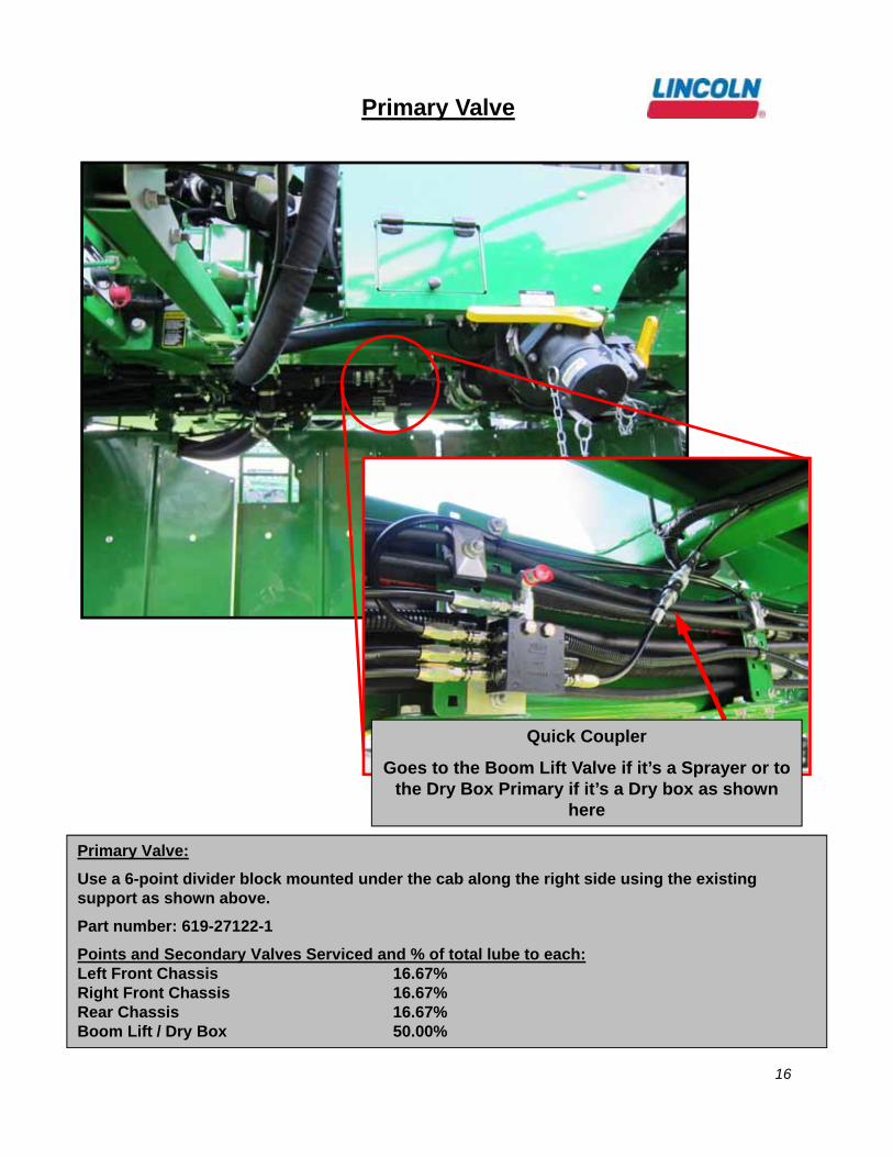
Primary Valve:
Use a 6-point divider block mounted under the cab along the right side using the existing support as shown above.
Part number: 619-27122-1
Points and Secondary Valves Serviced and % of total lube to each:Left Front Chassis 16.67%Right Front Chassis 16.67%Rear Chassis 16.67%Boom Lift / Dry Box 50.00%
Primary Valve
Quick Coupler
Goes to the Boom Lift Valve if it’s a Sprayer or to the Dry Box Primary if it’s a Dry box as shown
here

17
Left Front Chassis Secondary Valve
LINC
OLN
Rear Low
er Suspension Post
︵62"
︶
Frt Lower Suspension Post
︵62"
︶
Rear U
pper Suspension Post
︵62"
︶
Frt Upper Suspension Post
︵62"
︶
King Pin Lower
︵27"
︶
King Pin Upper
︵25"
︶
Steering Cylinder C
ap End
︵65"
︶
Steering Cylinder R
od End
︵64"
︶
619-26845-210-P
oint Valve
Left F
ron
t Ch
assisS
econ
dary V
alve
244055244053 (x4)
244054
244054
276407
242125
700506
244883 (x8)
247023 (x2)51304 (x2)
303-17499-3 (x2)
244053

18
The 10-point divider block mounted on the inside of the left wheel suspension.
Points Serviced:Suspension Post (4 points)Steering Cylinder Cap EndSteering Cylinder Rod EndKing Pin (2 points)
Left Front Chassis Secondary Valve
Mount block to the inside of this hose clamp.
Use this bolt to mount the valve
Steering Cyl Rod End
Kin Pin Upper
King Pin Lower
Steering Cyl Cap End
Suspension Post
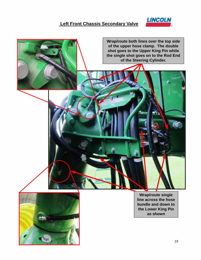
19
Left Front Chassis Secondary Valve
Wrap/route single line across the hose bundle and down to the Lower King Pin
as shown
Wrap/route both lines over the top side of the upper hose clamp. The double shot goes to the Upper King Pin while the single shot goes on to the Rod End
of the Steering Cylinder.

20
Left Front Chassis Secondary Valve
Split off into single line and wrap/route out to the Steering Cylinder
Rod End.
NOTE: Leave a loop (as shown) and secure to the post
with a zip tie

21
Left Front Chassis Secondary Valve
Follow and secure to the existing hose all the way
out to the point.
Wrap/route the Steering Cylinder Cap End along the existing hose bundle
right above the Lower King Pin point.

22
Left Front Chassis Secondary Valve
Secure bundle with P clamp using the existing
hardware shown
Wrap/route all four Suspension Post lines together and along the
existing loop as shown.

23
Right Front Chassis Secondary Valve
LINC
OLN
619
-26845-2
10-P
oint Va
lve
Rig
ht F
ron
t Ch
assisS
econ
dary V
alve
Rear Low
er Suspension Post
︵62"
︶
Frt Lower Suspension Post
︵62"
︶
Rear U
pper Suspension Post
︵62"
︶
Frt Upper Suspension Post
︵62"
︶
King Pin Lower
︵35"
︶
King Pin Upper
︵43"
︶
Steering Cylinder R
od End
︵57"
︶
Steering Cylinder C
ap End
︵65"
︶
24702
3 (x2)513
04 (x2)
242125
700506
276407
303-1
7499-3 (x2)
244
053 (x4)
2440
54
244055
244054
244053

24
The 10-point divider block mounted on the inside of the right wheel suspension.
Points Serviced:Suspension Post (4 points)Steering Cylinder Cap EndSteering Cylinder Rod EndKing Pin (2 points)
Right Front Chassis Secondary Valve
Use this bolt to mount the valve
The Right Front Chassis is identical in routing as the Left side with the exception of the King Pin Upper and Lower points which are on the back side of the King Pin.

25
Rear Chassis Secondary Valve
LINC
OLN
Frt LH Low
er Suspension Post
︵168"
︶
Frt LH U
pper Suspension Post
︵168"
︶
Rear LH
Upper Suspension Post
︵168"
︶
244053 (x8)
Rear LH
Lower Suspension Post
︵168"
︶
Frt RH
Lower Suspension Post
︵168"︶
Frt RH
Upper Suspension Post
︵168"
︶
Rear R
H U
pper Suspension Post
︵168"
︶
Rear R
H Low
er Suspension Post
︵168"
︶
276407247023 (x2)51304 (x2)
Rear C
hassis
Seco
nd
ary Valve
619-26646-28-P
oint Valve
244883 (x8)
242125
700506
26
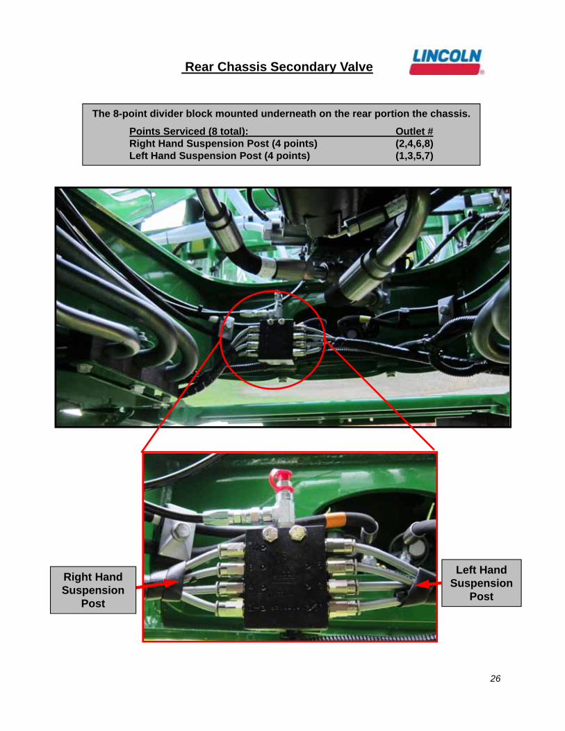
Left Hand Suspension
Post
Right Hand Suspension
Post
Rear Chassis Secondary Valve
The 8-point divider block mounted underneath on the rear portion the chassis.
Points Serviced (8 total): Outlet #Right Hand Suspension Post (4 points) (2,4,6,8)Left Hand Suspension Post (4 points) (1,3,5,7)

27
Rear Chassis Secondary Valve
Wrap/Route all four lines out both sides of the chassis here
Route the bundle along the existing hoses as shown
Route the bundle along the existing
hoses and P clip to the bracket as
shown
28
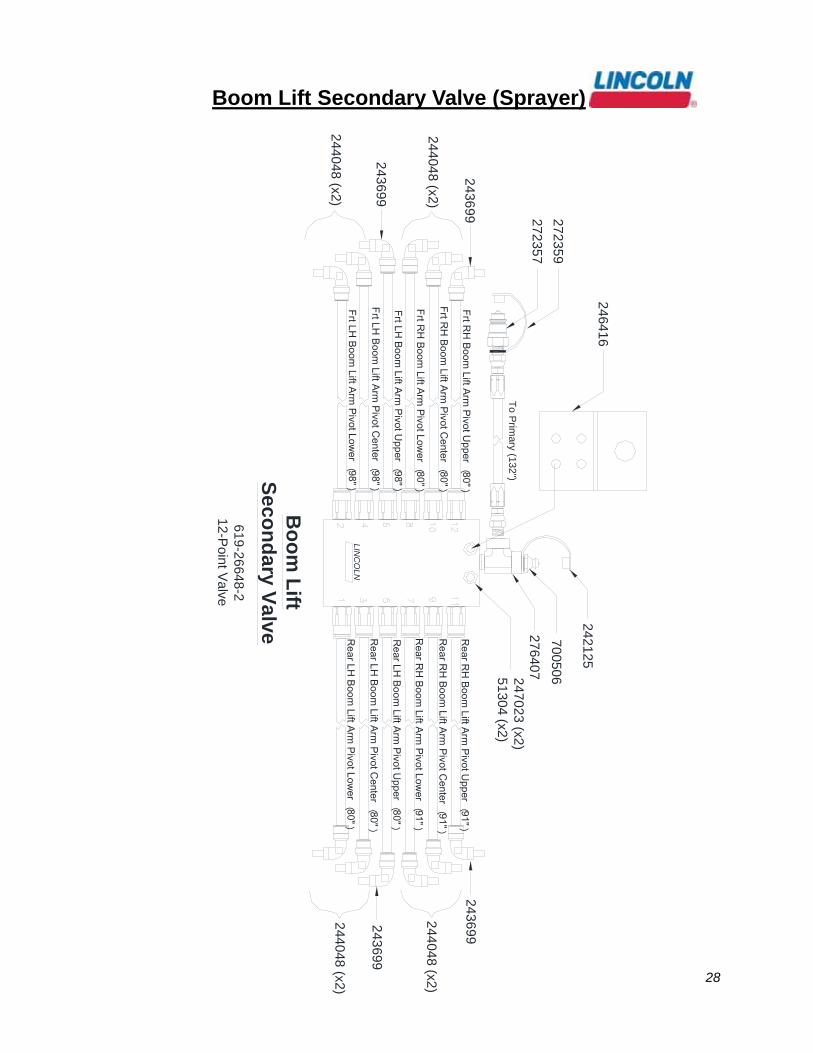
Boom Lift Secondary Valve (Sprayer)
Bo
om
Lift
Seco
nd
ary Valve
LIN
CO
LN
619-26648-2
12-Point V
alve
276407
242125
7005062
47023 (x2
)51
304 (x2)
Frt RH
Boom Lift Arm
Pivot Upper
︵80"
︶
Frt RH
Boom Lift Arm
Pivot Center
︵80"
︶
Frt RH
Boom Lift Arm
Pivot Lower
︵80"
︶
Frt LH Boom
Lift Arm Pivot U
pper
︵98"
︶
Frt LH Boom
Lift Arm Pivot C
enter
︵98"
︶
Frt LH Boom
Lift Arm Pivot Low
er︵98"
︶
Rear R
H Boom
Lift Arm Pivot U
pper
︵91"
︶
Rear R
H Boom
Lift Arm Pivot C
enter
︵91"
︶
Rear R
H Boom
Lift Arm Pivot Low
er
︵91"
︶
Rear LH
Boom Lift Arm
Pivot Upper
︵80"
︶
Rear LH
Boom Lift Arm
Pivot Center
︵80"
︶
Rear LH
Boom Lift Arm
Pivot Lower
︵80"
︶
243699
243699
243699
243699
244048
(x2)
244048
(x2)
244048
(x2)
24404
8 (x2)
246416
272357
272359
To P
rimary (132")
29
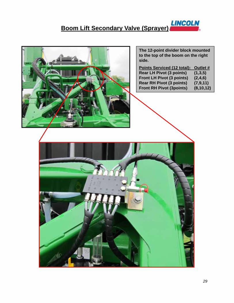
Boom Lift Secondary Valve (Sprayer)
The 12-point divider block mounted to the top of the boom on the right side.
Points Serviced (12 total): Outlet #Rear LH Pivot (3 points) (1,3,5)Front LH Pivot (3 points) (2,4,6)Rear RH Pivot (3 points) (7,9,11)Front RH Pivot (3points) (8,10,12)

30
Boom Lift Secondary Valve (Sprayer)
(Left Front Boom Pivots)
Left Front Boom Lift Arm Pivots
31
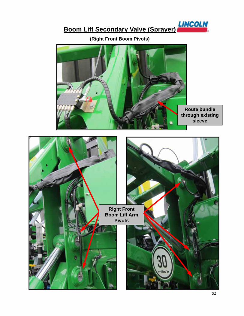
Right Front Boom Lift Arm
Pivots
Route bundle through existing
sleeve
Boom Lift Secondary Valve (Sprayer)
(Right Front Boom Pivots)
32
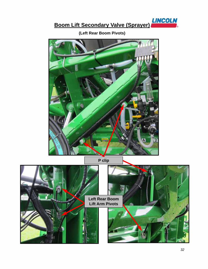
P clip
Left Rear Boom Lift Arm Pivots
Boom Lift Secondary Valve (Sprayer)
(Left Rear Boom Pivots)

33
Route bundle underneath strut and
attach to existing bundle as shown
Boom Lift Secondary Valve (Sprayer)
(Right Rear Boom Pivots)

34
Continue routing bundle along existing lines and
split off to the pivots
Boom Lift Secondary Valve (Sprayer)
(Right Rear Boom Pivots)
P clip
Right Rear Boom Lift Arm Pivots

35
System Primary to
Dry Box Primary Routing
1
2
3
4
5
6
Route up and across this support, attaching to the existing hoses
Exit from underneath the box through the
left side here.
Attach supply line along the existing metal tube
with zip ties
At the rear, route line down and
underneath with existing lines
Continue to follow the existing lines underneath
and bring supply line into the valve

36
Dry Box Primary Valve (Dry Box)
20031
2440472
0028
272658
242125
700
506
LH C
onveyor Idler Shaft
︵324"
︶
LH C
onveyor Dragshaft
︵48"
︶
*LH M
ultiplier Dragshaft
︵72"
︶
*LH C
onveyor Snubber Pulley
︵24"
︶
*RH
Multiplier Idler Shaft
︵84"
︶
RH
Conveyor D
ragshaft
︵84"
︶
*RH
Multiplier D
ragshaft
︵84"
︶
*RH
Conveyor Snubber Pulley
︵80"
︶
13154 (x2)
244048 (x2) 244
048
272357
272359
To
Prim
ary (200")
RH
Conveyor Idler Shaft
︵276"
︶
*LH M
ultiplier Idler Shaft
︵48"
︶
* Plug Points 3, 5, 8, 9, 11 and 12 With
303-17499-3 When N
ot Equipped With
A Multiplier
Dry B
ox
Prim
ary Valve
LIN
CO
LN
619-26648-212-P
oint Valve
276407
272427
272
401241288
246
002
Drybox Secondary
︵12"
︶
Mounted O
n Top Of D
ryBox Secondary Valve
244883 (x10)
2440472
0028
244047 20031
244047
24404720031
244
048

37
Dry Box Primary Valve (Dry Box)
The 12-point divider block stacked on top of the 6-point secondary block on the rear right side of the box.
Points Serviced (12 total): Outlet #Rear LH Pivot (3 points) (1,3,5)Front LH Pivot (3 points) (2,4,6)Rear RH Pivot (3 points) (7,9,11)Front RH Pivot (3points) (8,10,12)

38
Dry Box Primary Valve (Dry Box)
Right Snubber Pulley
Right Conveyor Dragshaft

39
Dry Box Primary Valve (Dry Box)
Route lines for LH Conveyor Dragshaft and
Snubber Pulley underneath and across
Left Snubber Pulley
Left Conveyor Dragshaft

40
Dry Box Primary Valve (Dry Box)
Remote manifold for the Multiplier bearings on the left side of the machine.
Left & Right Multiplier Dragshaft
Left & Right Multiplier Idler Shaft
41
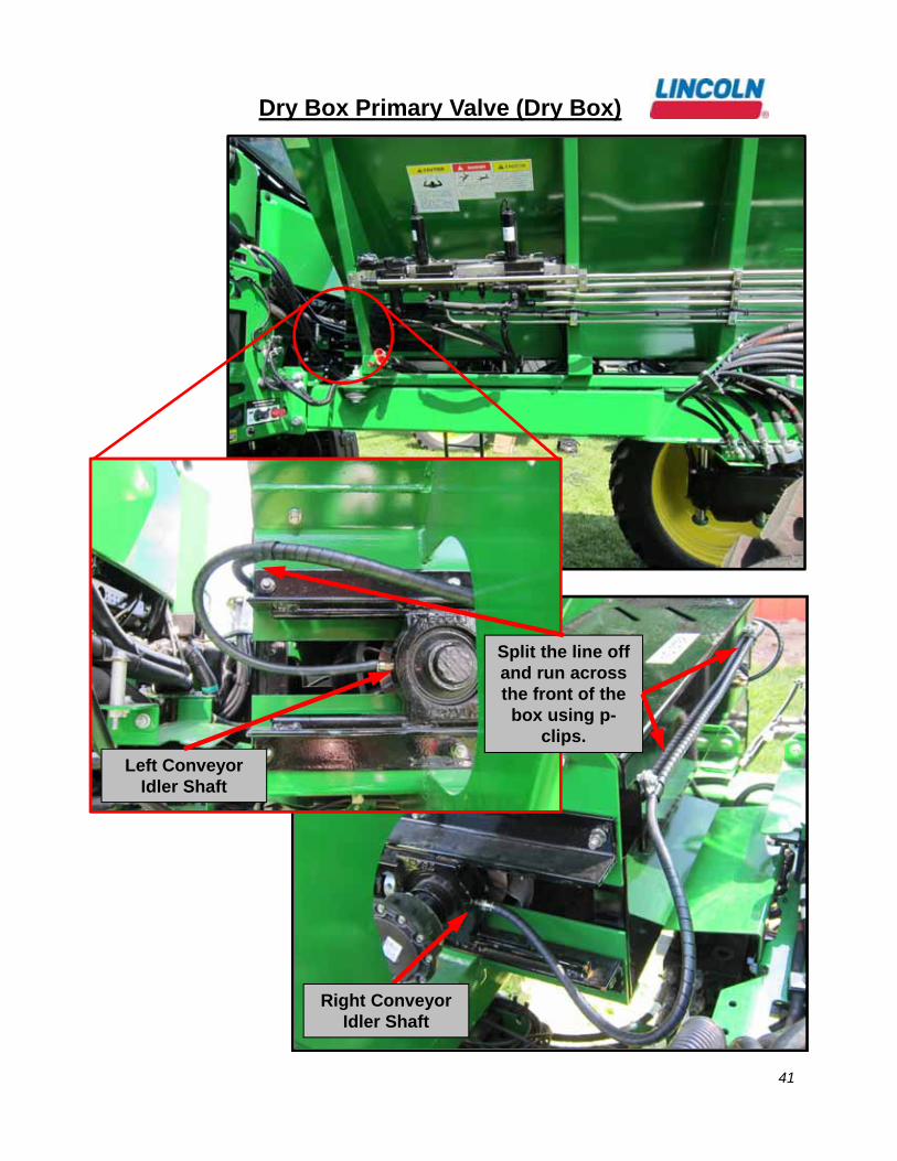
Dry Box Primary Valve (Dry Box)
Split the line off and run across the front of the box using p-
clips.
Left Conveyor Idler Shaft
Right Conveyor Idler Shaft
42
Dry Box Secondary Valve (Dry Box)
LINC
OLN
Spinner Tube
︵84"
︶
Spinner Tube
︵84"
︶
Spinner Jack
︵84"
︶Spinner Jack
︵84""︶
619-27122-16-P
oint Valve
Dry B
ox
Seco
nd
ary Valve
From
Dry B
ox Prim
ary
244053 (x4)* Points 3 & 4 Are U
sed toLubricate the Jackshaft G
ears& Tube W
hen Not Equipped
With A M
ultiplier
246416
247023 (x2)51304 (x2)
*303-17499-3
︵x2
︶

43
Dry Box Secondary Valve (Dry Box)
Mount Secondary block to bracket then
stack Primary on top of Secondary
Outlet #2 on Primary block
feeds the inlet of the Secondary
44
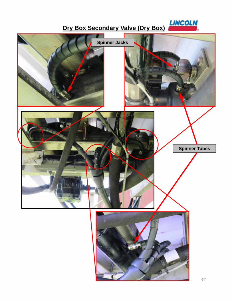
Dry Box Secondary Valve (Dry Box)
Spinner Jacks
Spinner Tubes

45
Daily Walk-Around Inspection
• The Lincoln Industrial Quicklub automated lube system components are designed, engineered, manufactured and assembled to the highest or quality standards. This lube system requires little or nor maintenance, however, to ensure maximum reliability and to realize maximum service life of all components, it is highly recommended that a daily walk-around inspection be performed.
• The daily walk-around inspection should include the following:
• Observe lubricant level in reservoir. Fill reservoir if it is low.
• Inspect high pressure relief at pump element, noting any lubricant buildup. If buildup is observed, correct this problem by determining cause of blockage.
• Inspect all valve and lube point connections to verify that no leaks are occurring.
• Inspect supply/feed lines to insure that no breaks or leaks have occurred.
• Inspect lube points to ensure that all lube points have a “fresh grease appearance.”
• Check pump operation by depressing push-button located in base of pump for two seconds to initiate a manual lube event. This will verify that pump is working (ignition switch must be on).
• Report or repair any problems found in this walk-around inspection immediately.
• NOTE: Operator to confirm operation of electric pump while machine is in service.
• NOTE: Report or repair any problem detected from daily inspection.

46
Note: Dirt and foreign material are the worst enemies of any lubricating system.Procedure
1. Use a manual pump with a gauge. Fill the pump with clean, filtered lubricant common to the system. Connect the manual pump into the inlet of the primary divider valve and slowly operate pump. If system will not cycle freely below 1,500 PSI, see Step 2.
2. With pressure on the primary as outlined in step 1, remove one at a time each supply line (if the supply lines cannot be removed, remove outlet fittings starting from the bottom and working towards the valve inlet) and attempt to operate manual pump after each line is removed. Do not exceed 2,000 PSI. If pressure drops and primary cycles freely after a line is removed then blockage is downstream in the area that is being served from that outlet. See Step 3. If all feed lines are removed and primary will not cycle, blockage is in this divider valve. Note: When a feed line of a blocked area is removed a small shot of trapped lubricant will usually surge out of this outlet as the inlet pressure on the divider valve drops. If testing in Step 2 indicates a blockage in the primary divider valve, this divider valve must be replaced.
3. Testing accomplished in Step 2 has indicated the blockage is downstream of the primary divider valve. Reinstall the feed line into the primary valve and proceed to downstream secondary divider valve and repeat step 2 on the secondary valve. If lubricant can be discharged freely through the secondary valve, the blockage is in the supply line between the primary and the secondary valve.
4. If high pressure exists on one of the secondary outlets, blockage has been located. Look for crushed line, tight bearing, improperly drilled fittings and/or lube inlet port. Correct as necessary.
Contamination
If dirt, foreign material or any other form of contamination is found as the source of the blockage, clearing the blockage will only temporarily solve contamination blockage problems. The source of the contamination must be eliminated for satisfactory service. The reservoir must be inspected and cleaned if necessary. The reservoir filling method should be reviewed to eliminate any chance of foreign material entering the reservoir during filling. All lubricating systems require filtered lubricant.
Grease Separation Blockage
If a hard wax or soap like material is found in the valve outlets, grease separation is occurring. This means that the oil is being squeezed from the grease at normal system operating pressure and the grease thickener is being deposited in the divider valve. Cleaning the divider valve will usually result in only temporarily solving the problem. Consult your lubricant supplier for recommendations on alternate lubricants and your local Lincoln Distributor to verify compatibility with centralized lubricating systems

47

48
Limited Warranty
Lincoln warrants the equipment manufactured and supplied by Lincoln to be free from defects in material and workmanship for a period of one (1) year following the date of purchase, excluding therefrom any special, extended, or limited warranty published by Lincoln. If equipment is determined to be defective during this warranty period, it will be repaired or replaced, within Lincoln’s sole discretion, without charge.
This warranty is conditioned upon the determination of a Lincoln authorized representative that the equipment is defective. To obtain repair or replacement, you must ship the equipment, transportation charges prepaid, with proof of purchase to a Lincoln Authorized Warranty and Service Center within the warranty period.
This warranty is extended to the original retail purchaser only. This warranty does not apply to equipment damaged from accident, overload, abuse, misuse, negligence, faulty installation or abrasive or corrosive material, equipment that has been altered, or equipment repaired by anyone not authorized by Lincoln. This warranty applies only to equipment installed, operated and maintained in strict accordance with the written specifications and recommendations provided by Lincoln or its authorized field personnel.
THIS WARRANTY IS EXCLUSIVE AND IS IN LIEU OF ANY OTHER WARRANTIES, EXPRESS OR IMPLIED, INCLUDING, BUT NOT LIMITED TO, THE WARRANTY OF MERCHANTIBILITY OR WARRANTY OF FITNESS FOR A PARTICULAR PURPOSE.
In no event shall Lincoln be liable for incidental or consequential damages. Lincoln’s liability for any claim for loss or damages arising out of the sale, resale or use of any Lincoln equipment shall in no event exceed the purchase price. Some jurisdictions do not allow the exclusion or limitation of incidental or consequential damages, therefore the above limitation or exclusion may not apply to you.
This warranty gives you specific legal rights. You may also have other rights that vary by jurisdiction.
Customers no located in the Western Hemisphere or East Asia: Please contact Lincoln GmbH & Co. KG, Walldorf, Germany.
Please refer to this manual for detailed information on operations, maintenance, trouble shooting and technical data. If you need additional information, please contact Lincoln Technical Services at 1-314-679-4200 ext. 4782# or fax 1-314-679-4357.To locate an authorized distributor, please visit the Lincoln distributor website at the following link:http://www.lincolnindustrial.com/asp/distributorlocator/distributors.asp?country=United+States