Embed Size (px)
Citation preview

JNET Project Life Cycle
12/24/2014 PA JNET i
Project Life Cycle
P E N N S Y L V A N I A J U S T I C E N E T W O R K
Version 0.40 12/31/2014
JNET Project Life Cycle
ii PA JNET 12/24/2014
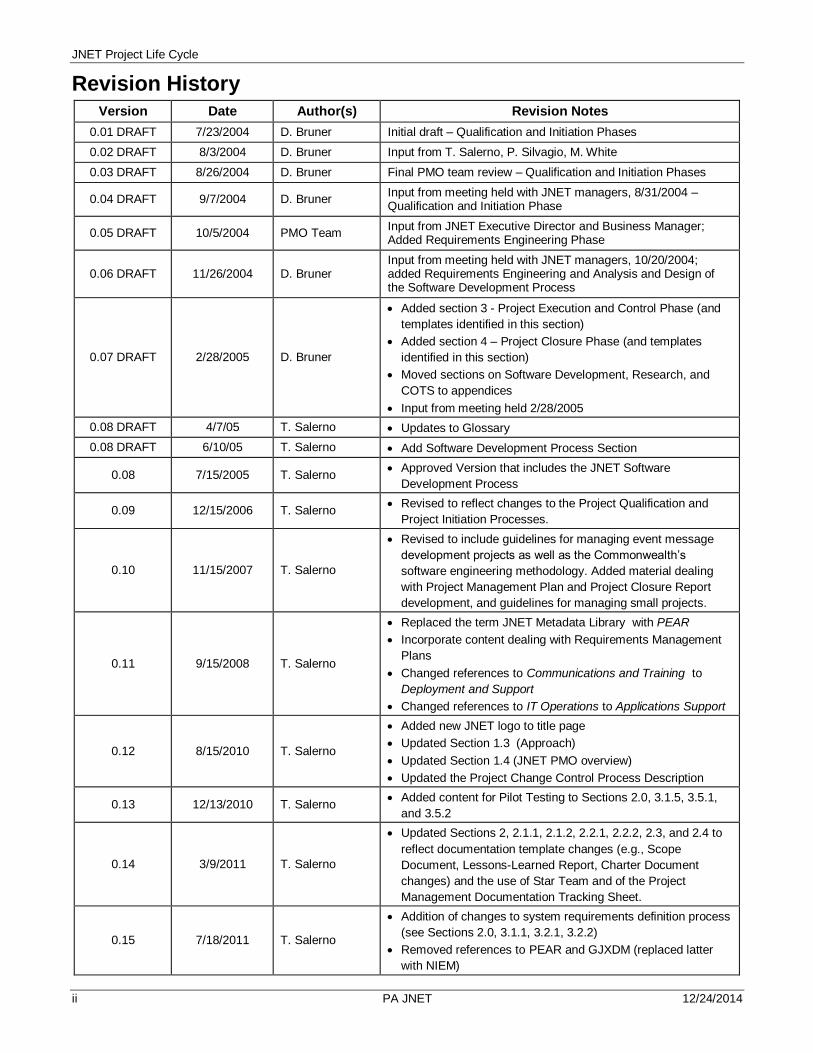
Revision History Version Date Author(s) Revision Notes
0.01 DRAFT 7/23/2004 D. Bruner Initial draft – Qualification and Initiation Phases
0.02 DRAFT 8/3/2004 D. Bruner Input from T. Salerno, P. Silvagio, M. White
0.03 DRAFT 8/26/2004 D. Bruner Final PMO team review – Qualification and Initiation Phases
0.04 DRAFT 9/7/2004 D. Bruner Input from meeting held with JNET managers, 8/31/2004 – Qualification and Initiation Phase
0.05 DRAFT 10/5/2004 PMO Team Input from JNET Executive Director and Business Manager; Added Requirements Engineering Phase
0.06 DRAFT 11/26/2004 D. Bruner Input from meeting held with JNET managers, 10/20/2004; added Requirements Engineering and Analysis and Design of the Software Development Process
0.07 DRAFT 2/28/2005 D. Bruner
Added section 3 - Project Execution and Control Phase (and
templates identified in this section)
Added section 4 – Project Closure Phase (and templates
identified in this section)
Moved sections on Software Development, Research, and
COTS to appendices
Input from meeting held 2/28/2005
0.08 DRAFT 4/7/05 T. Salerno Updates to Glossary
0.08 DRAFT 6/10/05 T. Salerno Add Software Development Process Section
0.08 7/15/2005 T. Salerno Approved Version that includes the JNET Software
Development Process
0.09 12/15/2006 T. Salerno Revised to reflect changes to the Project Qualification and
Project Initiation Processes.
0.10 11/15/2007 T. Salerno
Revised to include guidelines for managing event message
development projects as well as the Commonwealth’s
software engineering methodology. Added material dealing
with Project Management Plan and Project Closure Report
development, and guidelines for managing small projects.
0.11 9/15/2008 T. Salerno
Replaced the term JNET Metadata Library with PEAR
Incorporate content dealing with Requirements Management
Plans
Changed references to Communications and Training to
Deployment and Support
Changed references to IT Operations to Applications Support
0.12 8/15/2010 T. Salerno
Added new JNET logo to title page
Updated Section 1.3 (Approach)
Updated Section 1.4 (JNET PMO overview)
Updated the Project Change Control Process Description
0.13 12/13/2010 T. Salerno Added content for Pilot Testing to Sections 2.0, 3.1.5, 3.5.1,
and 3.5.2
0.14 3/9/2011 T. Salerno
Updated Sections 2, 2.1.1, 2.1.2, 2.2.1, 2.2.2, 2.3, and 2.4 to
reflect documentation template changes (e.g., Scope
Document, Lessons-Learned Report, Charter Document
changes) and the use of Star Team and of the Project
Management Documentation Tracking Sheet.
0.15 7/18/2011 T. Salerno
Addition of changes to system requirements definition process
(see Sections 2.0, 3.1.1, 3.2.1, 3.2.2)
Removed references to PEAR and GJXDM (replaced latter
with NIEM)

JNET Project Life Cycle
____________________________________________________________________________________________________iii PA JNET 12/24/2014
0.16 11/4/2011 T. Salerno
Removed references to Public Safety Deputy CIO
Added references to the CA2 Process in the sections dealing
with software development projects (Sections 3.2 to 3.6)
Removed references to and activities related to the obsolete
JNET Application Assessment System/Database.
0.17 12/12/2011 B. Alpaugh Updated Document to reflect SOA Projects
Added Glossary definitions for SOA references.
0.18 6/19/2012 T. Salerno
Updated various sections to reflect change in timing of
lessons-learned exercises and changes in Project Closure
Phase (i.e., made Lessons-Learned reporting optional,
modified Project Sponsor Satisfaction Survey).
Updated software development methodology to reflect
changes in CA2 process.
0.19 9/30/2013 T. Salerno
Updated link to Enterprise Project Management Methodology
(EPMM) in the Document Overview, Section 1.1.
Removed Event Message Development Section from Guide
Added the project sizing process to the Project Qualification
Phase.
Added references to Project Logs
Added PMO responsibility for new application system release
requests
Updated templates (Project Scaling, Deliverables Matrix,
Project Log, Project Communications Plan, New JNET
Application System Release Request
0.20 11/22/2013 T. Salerno
Corrected and updated out-dated information
Started section on managing JNET IT Infrastructure and
Product Upgrade Projects.
0.30 12/31/2013 T. Salerno Added Section 5 (IT Infrastructure and Product Upgrade
Projects)
0.31 2/6/2014 T. Salerno Added Project Team Member Performance Assessments to
Project Closing activities
0.40 12/31/2014 T. Salerno
Replace references to OIT-ETSO to PACS (throughout)
Updated references in Section 1.1
Added new Section 1.4 and moved JNET PMO Overview to
Section 1.5
Added optional component plans to the Project Management
Plan (pages 5, 14, 17)
Added information detail to Step 5 on page 12.
Added Stakeholder Management Plan component to Project
Management Plan content (pages 13 – 16)
Added PLC phase objectives and PMO activities on page 18
Added detail to the description of step 2 in the Project
Execution and Control process (page 21)
Added material from the Software Extension to the PMBOK
Guide Fifth Edition to Section 3.1 (page 25)
Made minor modifications to the Software Testing Process
Flow Charts and Descriptions (pages 42-44)
Modified Software Implementation Process Flowchart and
Description (pages 46-47)
Updated the Glossary

JNET Project Life Cycle
iv PA JNET 12/24/2014
Contents
REVISION HISTORY ........................................................................................................................................... II
1. INTRODUCTION ......................................................................................................................................... 1
1.1. DOCUMENT OVERVIEW .......................................................................................................................... 1 1.2. INTENDED AUDIENCE ............................................................................................................................. 1 1.3. APPROACH ........................................................................................................................................... 1 1.4. TYPICAL JNET PROJECT ROLES AND RESPONSIBILITIES ........................................................................... 2 1.5. JNET PROJECT MANAGEMENT OFFICE (PMO)......................................................................................... 2 1.6. TRACKING JNET PROJECTS ................................................................................................................... 2
2. JNET PROJECT LIFE CYCLE .................................................................................................................... 4
2.1. PROJECT QUALIFICATION PHASE .......................................................................................................... 11 2.1.1. Description – Qualification Phase ................................................................................................................. 11 2.1.2. Process Flow – Qualification Phase .............................................................................................................. 12
2.2. PROJECT INITIATION PHASE.................................................................................................................. 14 2.2.1. Description – Initiation Phase ....................................................................................................................... 14 2.2.2. Process Flow – Initiation Phase .................................................................................................................... 16
2.3. PROJECT EXECUTION AND CONTROL PHASE .......................................................................................... 19 2.3.1. Description – Execution and Control Phase .................................................................................................. 19 2.3.2. Process Flow – Execution and Control Phase ............................................................................................... 21
2.4. PROJECT CLOSURE ............................................................................................................................. 24 2.4.1. Description – Project Closure ....................................................................................................................... 24 2.4.2. Process Flow – Project Closure .................................................................................................................... 25
3. SOFTWARE DEVELOPMENT PROCESS ................................................................................................ 26
3.1 OVERVIEW OF JNET SOFTWARE DEVELOPMENT PROCESS ............................................................................ 26 3.1.1. Software Development Techniques .............................................................................................................. 26 3.1.2. Requirements Analysis................................................................................................................................. 26
3.1.2.1. What is a Requirement? ...................................................................................................................... 26 3.1.2.2. Types of Requirements ....................................................................................................................... 27
What is Requirements Engineering? ................................................................................................................................... 27 3.1.3. Software Architecture and Design................................................................................................................. 28
3.1.3.1. Typical Areas of Focus within Software Design .................................................................................... 29 3.1.3.2. Prototyping ......................................................................................................................................... 30 3.1.3.3. Design Reviews .................................................................................................................................. 30
3.1.4. Software Construction .................................................................................................................................. 31 3.1.5. Software Integration and Testing .................................................................................................................. 31 3.1.6. Software Implementation .............................................................................................................................. 32
3.2. REQUIREMENTS ENGINEERING.............................................................................................................. 33 3.2.1. Description – Requirements Engineering ...................................................................................................... 33 3.2.2. Process Flow – Requirements Engineering ................................................................................................... 34
3.3. SOFTWARE DESIGN ............................................................................................................................. 36 3.3.1. Description – Software Design...................................................................................................................... 36 3.3.2. Process Flow – Design................................................................................................................................. 37
3.4. SOFTWARE CONSTRUCTION ................................................................................................................. 39 3.4.1. Description – Software Construction ............................................................................................................. 39 3.4.2. Process Flow – Software Construction.......................................................................................................... 40
3.5. SOFTWARE TESTING ............................................................................................................................ 42 3.5.1. Description - Testing .................................................................................................................................... 42 3.5.2. Process Flow - Software Testing without Pilot ............................................................................................... 43
3.6. SOFTWARE IMPLEMENTATION ............................................................................................................... 46 3.6.1. Description - Implementation ........................................................................................................................ 46 3.6.2. Process Flow – Software Implementation ..................................................................................................... 47
4. SERVICE ORIENTED ARCHITECTURE (SOA) BASED DEVELOPMENT PROCESS .............................. 49
4.1. OVERVIEW OF JNET SOA BASED STANDARDS AND POLICY .................................................................... 49

JNET Project Life Cycle
____________________________________________________________________________________________________v PA JNET 12/24/2014
4.2. OVERVIEW OF JNET SOA BASED DEVELOPMENT PROCESS .................................................................... 49 4.2.1. Service Requestor ....................................................................................................................................... 49 4.2.2. Data Provider............................................................................................................................................... 50 4.2.3. JNET as a Service Provider.......................................................................................................................... 50
4.3. PHASES ............................................................................................................................................. 50 4.3.1. Requirements Engineering ........................................................................................................................... 51 4.3.2. Software Design .......................................................................................................................................... 51 4.3.3. Software Construction, Testing and Implementation ...................................................................................... 52
4.4. CONFIGURATION DIFFERENCES ............................................................................................................ 52 4.4.1. Business Partner Requesting Information ..................................................................................................... 53 4.4.2. Business Partner Providing Information ........................................................................................................ 55 4.4.3. JNET Applications using Web Services ........................................................................................................ 57
5. IT INFRASTRUCTURE AND PRODUCT UPGRADE PROCESS............................................................... 60
5.1. OVERVIEW .......................................................................................................................................... 60 5.2.1 Planning ...................................................................................................................................................... 60 5.3.1 Analysis ....................................................................................................................................................... 61 5.4.1 Design ......................................................................................................................................................... 62 5.5.1 Validation .................................................................................................................................................... 63 5.6.1 Production Implementation ........................................................................................................................... 64
6. GLOSSARY .................................................................................................................................................. 65

JNET Project Life Cycle
vi PA JNET 12/24/2014
This page is intentionally blank.
JNET Project Life Cycle
12/24/2014 PA JNET 1
1. Introduction
1.1. Document Overview
This document, comprised of the sections listed below, provides the guidelines and tools needed to successfully and consistently initiate, control, and deliver JNET projects:
Introduction – introduces JNET’s Project Management Office (PMO) and sources of
JNET projects to be managed through the Project Life Cycle.
Project Life Cycle (PLC) Overview – provides a high-level introduction to JNET’s tailored
PLC for different types of JNET projects.
PLC Phase Descriptions – depict the description and process flow of each of the major
PLC phases.
This methodology is based on the principles outlined within the following:
Commonwealth of Pennsylvania’s Office of Administration Information Technology (OA-
OIT) Enterprise Project Management Methodology:
https://itcentral.pa.gov/ProjectManagement/Methodologies%20Roadmaps%20and%20To
olkits/Project%20Management%20Process%20Guide%202.0.docx
The Project Management Institute’s (PMI) Project Management Body of Knowledge
(PMBoK)
1.2. Intended Audience
This document is geared towards JNET’s professional staff, and the assumption is made that the staff is familiar with project management and software development practices and procedures. This document is not an all-inclusive textbook on project management or systems development.
1.3. Approach
The PMO’s vision is to streamline processes and apply guidelines that truly add value to JNET’s project portfolio.
JNET’s PLC has been developed and released by major phases (e.g., Qualification, Initiation, etc.). Input has been solicited from staff members to tailor the guidelines to JNET’s unique needs. The PMO is striving for continuous process improvement and welcomes ongoing comments and suggestions.
This will be a living document in that initial releases will represent a foundation on which to build based on knowledge gained over time. One challenge associated with this approach is to keep all staff members informed and up-to-date. The PMO communicates through the following channels:
JNET Staff Meetings
Project Planning Meetings
Project Status Meetings and Reports
Bi-weekly Critical Path Projects Status Meetings
A central tenet of project management at JNET is to never allow process to become a roadblock
to achievement. Consequently, this PLC is intended to be a guide only, not a rigid standard. The
document suggests a set of project management documentation, but does not require that the
entire set be produced for every project. In reality, the amount of project documentation varies
from project to project, depending on duration, complexity, risk and cost. The results of a project
sizing exercise dictates which project management artifacts must be produced for any given
JNET project (ref. Section 2.1)

JNET Project Life Cycle
2 PA JNET 12/24/2014
1.4. Typical JNET Project Roles and Responsibilities
Project Sponsor (or Initiator) – Person who provides support and approvals throughout the life of the project. They may also have initiated the project. For JNET projects, it is usually the JNET Executive Director.
Stakeholder – Persons or organizations that are involved in and influence the project. Stakeholders can include the Project Sponsor, Functional Managers, the Project Manager, the project team, project product end-users, the public, and funding sources.
Project Manager – Person who has overall responsibility for managing the project from the first formal documentation of the project’s initiation to its formal conclusion,
Project Team – Team responsible for performing project tasks as defined by the Project Manager.
Functional Managers – Individuals who hire and manage the day-to-day, non-project work activities of staff assigned to various functional areas of JNET, including IT Application Development, IT Application Support, the Business Office, Communications Office, and the Budget and Administration Office. They typically fill requests of Project Managers for Project Team members, and help oversee project activities performed by their staff members.
Business Lead – Person who provides business expertise and leadership for the project. This role is typically filled by the JNET Business Manager, JNET Security Officer, or JNET Business Analyst.
Technical Lead – Person who provides technical expertise and leadership for the project. At JNET, this is usually the JNET Application Development Manager or the JNET Application Support Manager.
1.5. JNET Project Management Office (PMO)
The Pennsylvania Justice Network (JNET) has seen significant growth in a number of areas including system functionality, the number of JNET member organizations as well as the number of end users. Anticipated continued growth challenges JNET to respond to change such that the ‘status quo’ in delivering system updates is no longer adequate. JNET’s PMO was established in the year 2004 with the following objectives:
To serve as a central control point for managing JNET’s project portfolio.
To develop a JNET-tailored PLC that introduces and layers project management
techniques with software development practices.
To serve as a center for excellence to champion improvement of project management
(e.g., reduction in schedule overruns; satisfaction of project sponsors or stakeholders;
satisfaction of Project Team Members).
Since that time, the PMO has evolved and, in addition to managing JNET’s major projects and
maintaining the JNET PLC, it also:
Serves as a central resource for JNET Management to get information about its projects
and major non-project activities.
Provides Resource Allocation Planning Support—i.e., helps ensure that the right staff
resources are assigned to the right projects at the right time.
1.6. Tracking JNET Projects
JNET’s five-year Strategic Plan, the most recent version to be published in December 2014, identifies JNET’s strategic goals. JNET’s annual Business Plan identifies specific projects and links the projects to the goals in the Strategic Plan.
The Critical Path Projects List represents JNET’s project portfolio. Critical Path projects originate in a number of ways:
Projects are identified within JNET’s annual Business Plan

JNET Project Life Cycle
____________________________________________________________________________________________________3 PA JNET 12/24/2014
Project are identified through various channels to request or require JNET support of
integrated justice system (or other) mandates
Users’ requests for enhancements passing JNET’s project ranking criteria
A bi-weekly meeting is held with JNET’s Managers, Team Leads, Business Analysts and the PMO team to review priority, status, and issues for projects appearing on the Critical Path List.
Strategic
Plan
Goals Business
Plan
Projects to Achieve Goals
Critical Path
List
JNET Executive-Level Project List
‘Qualified’ User
Requests
‘Mandated’
Requests

JNET Project Life Cycle
4 PA JNET 12/24/2014
2. JNET Project Life Cycle
The JNET PLC provides a framework to consistently plan and successfully execute projects. JNET’s PLC addresses project management methodologies as well as other processes that are routinely undertaken, including:
Software Development – where JNET staff designs and implements applications,
modules, or systems supporting its integrated justice network.
Service Oriented Architecture (SOA)-Based Development – where JNET staff designs,
constructs and implements applications utilizing the Information Service Bus (ISB) using
SOA architecture.
Commercial-off-the-Shelf (COTS) Procurement and Integration – where JNET procures a
third-party vendor product and the JNET staff (or other contract staff) works to integrate
the product into JNET’s architecture.
IT Infrastructure Upgrades – where JNET staff teams with PA Compute Services (PACS)
to upgrade its major IT infrastructure, including servers, networking technology, database
management systems, desktop and mobile computers, ISB middleware and messaging
components.
The PLC addresses all aspects of typical JNET projects. The project management aspects of the major project phases remain constant regardless of the project type, while the detailed (or process-level) activities vary within the Project Execution and Control phase depending on the project type.
Project Qualification Phase
Section 2.1
Project Initiation and
Planning Phase Section 2.2
Software Development
Process Section 3
COTS Procurement
and Integration
Process TBD
SOA-Based Systems
Development Section 4
Project Closure
Section 2.4
Project Execution and Control Phase Section 2.3
IT Infrastructure
Upgrades
Section 5

JNET Project Life Cycle
____________________________________________________________________________________________________5 PA JNET 12/24/2014
The following is a summary of JNET’s PLC phases as well as inputs and outputs of each phase. Each of the phases is described in further detail in the following sections.
PLC Phase / Process Inputs Outputs
Project Life Cycle
Qualification
Commits JNET to begin the next phase of the project
JNET Annual Business Plan
Steering Committee or JAAS
Request
Governor’s Office Request
JNET Resource Allocation Plan
Project Scaling Worksheet
Project Charter
Updated Project Priority List
Updated Critical Path Projects Report
Updated Resource Allocation Plan
Updated Project Management Documentation
Tracking Sheet
Initiation and Planning
Involve all appropriate stakeholders to help develop a project management plan, define the project scope, create a work breakdown structure (WBS), and develop an initial project schedule.
Approved Project Charter
Results from project definition
meetings
Resource Allocation Plan
Project Planning Templates
o Project Management Plan
o Work Breakdown Structure
o Project Schedule
Approved Project Management Plan
o Resource Management
o Communications Management
o Schedule (Time) Management
o Scope Management
o Requirements Management (Optional)
o Configuration Management (Optional)
o Release and Deployment (Optional)
o Quality Management (Optional)
o Risk Management (Optional)
Approved Scope Document (Optional)
Deliverables Responsibility Matrix
Project Log
Approved Initial Project Schedule
Initial Lessons-Learned Report (Optional)
Updated Resource Allocation Plan
Updated Critical Path Projects Status Report

JNET Project Life Cycle
6 PA JNET 12/24/2014
PLC Phase / Process Inputs Outputs
Project Execution and Control
Provides for the completion of project tasks as well as monitoring, reporting and communicating status, progress, change and variances to the project’s scope, budget or schedule
Project Control templates- Meeting
Agenda, Meeting Minutes, Project
Log, Project Change Request Form,
Project Status Report
Project Deliverables Schedule
Work Breakdown Structure (WBS)
Resource Allocation Plan
Weekly or Bi-Weekly
o Project Schedule indicating % Complete
o Project Status Report (Optional)
o Updated Project Log
o Updated Critical Path Projects Status
Report
Monthly
o Project Status Report (required)
o Updated Resource Allocation Plan
As Required
o Meeting Agendas
o Meeting Minutes
o Change Request Form
o Updated Project Management Plan
o Updated Project Management
Documentation Tracking Sheet
End of Phase
Updated Lessons-Learned Report (Optional)
Project Closure “Lessons learned” captured during
the project
End-of-project meeting
Project Sponsor/Stakeholder
Satisfaction Survey
Lessons-Learned Report
Project Closure Report
Individual or team performance appraisals or
recognition
Updated Critical Path List
Software Development Process
Requirements Engineering
Defines user and other business processes and needs and sets expectations for an approach to testing
Requirements Management Plan
Decisions and results of discussions
relating to a Requirements Modeling
approach
Decisions and results of data
gathering activities
Decisions and results of discussions
relating to high-level test planning
Outcome of peer review of
requirements
Approved Requirements Specification
Document (RSD)
Approved Requirements Traceability Matrix
Application System Mock-Up (Optional)
Updated Project WBS/Work Plan
Software Design Approved Requirements
Specification Document (RSD)
CA2 Initiation
System Mock-Up (Optional)
Approved Design Package
Updated and Approved Requirements
Traceability Matrix
System Prototype (Optional)
Approved CA2 Initiation
Updated Project WBS/Work Plan

JNET Project Life Cycle
____________________________________________________________________________________________________7 PA JNET 12/24/2014
PLC Phase / Process Inputs Outputs
Software Construction Approved Design Package
Approved System Prototype
(Optional)
Final approved Purchase Orders for hardware
and software
Approved Application System Code
Approved Test Plan and Test Cases
Approved Deployment Document
Updated WBS/Work Plan
Software Testing Approved Application System Code
in Installed in Test Environment
Approved Test Plan and Cases
Approved Pilot Test Plan and Survey
New system release request
template
Source Code security vulnerability
scans
Approved Internal Test Results Report
Approved Pilot Test Results Report
Training Materials
Communication to End-Users and Technical
Partners
CA2 Certification
Approved Release Request
Approved Updated Deployment Document
Approved Updated Requirements Traceability
Matrix
Updated Project WBS/Work Plan
Software Implementation CA2 Accreditation Activities
Approved Release Request
Approved Updated Deployment
Document
Application Code in the PROD
Environment
Accredited Software (CA2) or Remediation
Plan
Approved Operable System in the PROD
Environment
Approved Updated Requirements Traceability
Matrix
Updated Project WBS/Work Plan

JNET Project Life Cycle
8 PA JNET 12/24/2014
PLC Phase / Process Inputs Outputs
Service Oriented Architecture (SOA)-Based Development Process
Initiation Online Web Services Access Request Form
Data Source agreements with consumers
Business process details
JNET and NIEM documents
Service security and message payload
Approved Web Services Access Request form
Service Level Agreement (new or updated)
Initial data element identification
Planning Business Requirements Gathering
Requirements Analysis
Service Orchestration Architecture
Technical Requirements
User Interface Requirements (if necessary)
Architectural Design and Security
CA2 Initiation
Business and UI Requirements Specification document
Technical requirements specification document
Design Document
Approved architectural design document
Approved CA2 Initiation – Move to Certification/Accreditation
Sample XML
Service Description Document (SDD)
Initial SSP
IEPD Data Element Dictionary
IEPD Domain Model
Execution Web Services Description Language (WSDL)
Schemas and Samples
Software Design
Software Development
Software Integration
Software Testing
CA2 Certification Activities
Design Document
User Interface
Web Service
Database
User transaction log and Audit Log
Completed Test Report
Production Deployment Completed and approved artifacts
(including deployment instructions)
Fully tested message processing components residing in the JNET Test environment
Deployment documentation
CA2 Accreditation Activities
UI deployed to Production
Web Service deployed to Production
Accredited Web Service
Application monitored by JNET Web Services Monitoring Tool
Completed SSP
COTS Integration Process (To be Developed)

JNET Project Life Cycle
____________________________________________________________________________________________________9 PA JNET 12/24/2014
IT Infrastructure and Product Upgrades
Phase Inputs Outputs
Planning Vendor information about upgrade
Current product licensing information
PACS readiness to support
infrastructure item/product
PACS resources availability (including
POC or PM)
JNET Configuration MindMap
Impacted JNET Application Systems
Identification
JNET Staff Resources Skills
Assessment
Vendor POC Identification
Vendor Resources Identification
Impacted Documentation
Identification
JNET Project Qualification Inputs (see
above)
PACS Procurement process
JNET Project Qualification Outputs (see
above)
Project Team Roster (including PACS and
vendor Staff)
Purchase order initiation (if necessary)
Analysis Project Initiation Inputs (see above)
Current infrastructure review
Current product licensing assessment
Systems analysis resource(s)
Areas of improvement targeting
System requirements and
performance metrics identification
Project Initiation Outputs (see above)
Technical (system) requirements
Specification Document
Product procurements (if necessary)
Design Technical (system) requirements
specification
Architectural design resource(s)
Review and assessment of existing
infrastructure design specifications
Consultation with PACS and/or
Vendor
Project Execution and Control inputs
(see above)
Detailed Infrastructure Design Specs
New or updated MSL Document
Detailed implementation strategy
Approved validation/test plan
Project Execution and Control Outputs (see
above)

JNET Project Life Cycle
10 PA JNET 12/24/2014
Validation Project Execution and Control
activities
Detailed implementation strategy
Approved validation/test plan
Procured infrastructure components
(if applicable)
Infrastructure components installed in
DEV and TEST environments
Deployment and Testing resources
Applications deployed to new
infrastructure components in DEV and
TEST environments
Test results report: implementation strategy
validated
Infrastructure upgrades and applications
performing reliably in DEV and TEST
Approval to proceed
Deployment Plan/Instructions
Production Implementation Project Execution and Control
activities
Deployment and Test resources
Procured infrastructure components
(if applicable)
Deployment Plan/Instructions
Infrastructure components released to
production/ops environment
Applications released to new production/ops
environment
Production checkout report
Updated JNET Configuration MindMap
Purchase order delivery
Post-Implementation Review Project Closure Inputs (see above) Project Closure Outputs (see above)

JNET Project Life Cycle
____________________________________________________________________________________________________11 PA JNET 12/24/2014
2.1. Project Qualification Phase
2.1.1. Description – Qualification Phase
The objectives of the Qualification Phase include:
Receive and consolidate ideas for undertakings relating to JNET.
Categorize incoming ideas and requests (as projects, non-project system enhancements, message-
processing requests, etc.)
Rank and prioritize proposed projects (in relation to other JNET projects).
Participants JNET Steering Committee and JNET Agency Advisory Subcommittee (JAAS)
Project Requestor and/or Project Sponsor
JNET Executive Director and Managers
JNET PMO
Activities / PMO Checklist
Schedule and conduct initial meetings with Requestors, as necessary, to gather information needed for the work products/deliverables.
Open Project Documentation Repository in Star Team
Work Product(s) / Deliverables
Project Scaling Worksheet
Project Charter –
o Abridged Version (for Level Three projects):
Project Description (Background, Objectives, Scope, Customers)
Project Roles and Responsibilities (Sponsor, PM, Stakeholders, Core Team)
Project Information (Deliverables, Assumptions, Constraints, Risks, Dependencies with Other Projects, Success Criteria)
Approval Signatures
o Comprehensive Version (for Level One or Two Projects)
Business Case (including cost savings potential and formula to be used)
JNET Strategic Plan Alignment
Project Management Team Identification (Sponsor, PM, Business Owner)
Statement of Work
Objectives
Deliverables
Preliminary Scope (what is in and out of scope)
Project Risks (including an assessment of likelihood and impact)
Assumptions
Success Criteria
General Timeline
Staffing (JNET and External)
Approval Signatures
Project Prioritization Spreadsheet
Project Review and Approval by Sponsor(s)
Updated JNET Critical Path Projects List
Updated Project Documentation Tracking Spreadsheet
Updated JNET Resource Allocation Plan

JNET Project Life Cycle
12 PA JNET 12/24/2014
Tools and Templates
Project Scaling Worksheet
JNET Project Charter (Comprehensive and Abridged versions)
Business Case Analysis
Project Prioritization Scorecard
Critical Path Projects List
2.1.2. Process Flow – Qualification Phase
1 Potential JNET Projects typically are identified via the annual Business Plan development process, via formal and informal requests from the JNET Steering Committee, JNET Agency Advisory Subcommittee, Governor’s Office, or the Secretary of Administration.
2 At the direction of the JNET Executive Director or the JNET Business Manager, the PMO reviews requests or Business Plan activities to determine disposition.
If the request is not approved to move forward, the JNET Executive Director, Business Manager, or PMO contacts the requestor to provide an update and explanation for the disposition.
1 JNET Annual
Business Plan, Steering
Committee or JAAS request
Deliverable
2 PMO reviews Business
Plan or request and Initiates preliminary
discussion with JNET Executive Director to determine disposition
7 JNET’s Executive Director and other
Project Sponsors (if any) reviews and approves the work effort as a JNET
Project
6 Project Manager
completes a project charter
Deliverables
8 PMO coordinates a
project priority scoring, and places the project on the
Critical Path Report. Opens a project in
Star Team, and updates the JNET
Resource Allocation Plan
Deliverables
4 PMO determines if
request is a potential project
3 PMO initiates discussions to
gain more information
5 Project Manager performs a project scaling exercise using the scaling
worksheet
Project Initiation
Phase

JNET Project Life Cycle
____________________________________________________________________________________________________13 PA JNET 12/24/2014
3 If JNET’s Executive Director or Business Manager approves the request to be assessed as a potential project, the PMO initiates discussions with the Requestor, as well as selected members of the JNET Office Staff, to gather the information required to complete this phase’s deliverables.
4 The PMO reviews the request to make a final determination as to whether or not the request represents a potential project, defined as a temporary endeavor undertaken to create a unique product, service, or result.
If the PMO determines that the request is not a potential project, it will report it and assign it to the IS staff as an application system enhancement request or as a system maintenance activity.
5 If the PMO determines that the request is a potential project, the PMO Lead assigns a Project Manager who in turn gathers enough information from the project planning participants to scale or size the project, using the Project Scaling Worksheet. Projects are then classified as Level One, Two, or Three. A Level Three project is considered to be the least complex; Level One the most complex. The scaling score is used as a guide to determine the amount of project management rigor applied to the project, as well as the number of required project management deliverables.
6 The Project Manager then completes an initial draft of the Project Charter. If the Project is deemed to be Level Three, an abridged version of the Charter is used. If the project is a Level One or Two, a comprehensive version of the Charter is written. After review by the PMO Lead, the Project Charter is submitted to JNET’s Executive Director and other Project Sponsors (if any) for review and approval.
7 The JNET Executive Director reviews and approves the work effort as a project to be managed through the PMO. If additional Project Sponsors are identified, they are asked to approve the Project Charter.
8 If the project is approved, the assigned Project Manager will coordinate a project prioritization exercise that involves the JNET management staff in assigning a score based on defined criteria, including: alignment with JNET goals and mission statement, urgency, impact on JNET’s operating budget, cost savings potential, agencies and number of users impacted, JNET staff resources impacted, partner agency readiness, and impact on service levels. The higher the score attained, the higher the project priority. The PM also will open a Project in Star Team, where the project documentation will be stored. The Project Management Lead will add the project to the Project Documentation Tracking spreadsheet, the Critical Path Projects Status Report and the Resource Allocation Plan.
If the project is not approved, the PMO follows up with the requestor. The project request can be retained in the repository for consideration in the next planning year.

JNET Project Life Cycle
14 PA JNET 12/24/2014
2.2. Project Initiation Phase
2.2.1. Description – Initiation Phase
The objectives of the Initiation Phase include:
Identify Project Team Members.
Thoroughly define a formal plan for managing the project.
Ensure involvement, communications, and commitment of Project Sponsors or Stakeholders who
identified the need for the project as well as JNET Project Team Members.
Participants JNET PMO
JNET Managers and Team Leads
Partner Agencies Management
Project Team Members (JNET and External)
Activities / PMO Checklist
Schedule and conduct project planning meeting(s)
Stakeholder identification and needs analysis
Prepare initial Project Management Plan that includes (at a minimum):
o Communications Management Plan
o Change Management Plan
o Issues Management Plan
Large or complex projects require, in addition to the above :
o Stakeholder Management Plan
o Resource Management Plan
o Scope Management Plan
o Risk Management Plan
o Schedule Management Plan
Optionally, small or large software systems development projects might include:
o Requirements Management Plan
o Configuration Management Plan
o Quality Management/Testing Plan
o Release and Deployment Plan
Have Communications Plan reviewed and approved by OA’s PR Staff (optional)
Prepare a Project Log
Schedule and conduct a Project Kickoff Meeting
Define Project Scope
Develop a Project Deliverables Responsibility Matrix
Conduct meetings with project stakeholders / sponsors to present, review, and gain approval of the initial Project Schedule
Conduct interim “lessons-learned” session (optional)
Update the Project Management Documentation Tracking Spreadsheet
Work Product(s) / Deliverables
Project Management Plan:
o Key Project Charter components
o Stakeholder Management (optional)
o Resource Management (optional)
o Communications Management
o Schedule (Work Plan) Management
o Scope Management (optional)
o Requirements Management (optional)
o Risk Management (optional)
o Issues Management
Project Log

JNET Project Life Cycle
____________________________________________________________________________________________________15 PA JNET 12/24/2014
o Project Charter (Level Three Projects)
o Project Schedule (Level Three Projects)
o Communications Plan (Level Three Projects)
o Project Issues and Action Items
o Project Risk Register
o Project Decisions Log
o Project Change Register
Project Kickoff Meeting:
o Team Introductions
o Sponsor(s) Statement(s)
o Project Management Plan Review
o Roles and Responsibilities
Project Scope Definition and High-Level Requirements:
o High-Level Scope Statement (from Charter)
o High-Level Functional and Operational Requirements
o Deliverables
o Affected Organizations, Systems and Processes
o Specific Exclusions from Scope
o Governance Structure and Resource Requirements
o Overall Project Risk
Initial Project Deliverables Schedule
o Deliverables and Assigned Staff Resources
o High-Level Estimates to Complete Each Deliverable
Initial Lessons-Learned Report (optional)
Updated Project Documentation Tracking spreadsheet
Updated Critical Path List
Tools and Templates
Project Charter (two versions)
Project Management Plan (optional components, depending on project size and complexity)
Project Scope Definition Enterprise Template
Project Deliverables Responsibility Matrix and High-Level Schedule Template
Lessons-Learned Report Template (optional)
Project Control Documents
o Meeting Agenda
o Meeting Minutes
o Project Log
o Project Status Report
o Change Request Form

JNET Project Life Cycle
16 PA JNET 12/24/2014
2.2.2. Process Flow – Initiation Phase
1 The assigned PM and PMO Lead review all gathered information to determine the project type:
Software Development
webMethods (SOA) Development
COTS Project
Infrastructure Upgrade
and scale:
Level Three – least complex, visible, costly
Level Two
Level One – most complex, visible, costly
The PM will customize the Project Management Plan and Schedule/Work plan based on the
Project Type and Scale.
2 The assigned PM schedules and conducts project planning meetings to review the Project Charter and start developing an optional, formal Project Scope Statement.
The PM invites JNET Managers and/or potential JNET Project Team Members to these meetings to determine who will be assigned to the project. All departments, listed below, should be represented at these early meetings to ensure the appropriate levels of resources are identified throughout the life cycle:
Business Office
Communications
Systems Development
Quality Assurance
JNET Applications Support
If external staff resources are required, it is essential that they be identified as well as a Lead or
Critical Path Project
(Approved JNET Project)
1 JNET PMO Team
Lead and assigned PM review the
project and identify the project type and
scale
2 Assigned PM
identifies potential team members and
conducts project planning meetings
4 PM schedules and conducts a Project
Kickoff Meeting
Project Execution and Control Phase
Project Management
Plan executed
3 PM develops a
Project Management
Plan Deliverable
5 PM and Project
Team define project scope
(including deliverables and
high-level requirements)
Deliverable
6 PM and Project Team produce a
Deliverables Responsibility
Matrix and high-level schedule
7 PM performs other
project startup activities

JNET Project Life Cycle
____________________________________________________________________________________________________17 PA JNET 12/24/2014
point-of-contact (POC) from the participating agency or organization. All meeting participants will
represent their functional area or area of expertise and will provide input to project definition and
planning, which addresses the following:
Task planning
Risk management
Quality management
Issues management
Documentation and deliverables
Resource management and tracking
Procurement control and reporting (if applicable)
Communications
Requirements management
Project performance evaluation
3 Based on input received during the project planning meetings, the PM drafts the Project Management Plan which describes in detail how the Project will be managed. At a minimum, for Level Three projects, the plan should include a Communications Plan, a Change Management Plan and an Issues Management Plan. Level One and Two Projects should include, in addition, plans for managing stakeholders, resources, scope, schedule, and risk. Software Systems development projects can optionally include a Requirements Management Plan, System Testing Plan, Configuration Management Plan, and Deployment and Release Management Plan.
A. Stakeholder: Identifies project stakeholders, their level of influence, expectations or requirements. It also describes how the project will communicate with them, and how they will be involved in and kept engaged in the project.
B. Resource: Defines how resources will be (or have been) selected and how their performance will be managed, and when and how they will be released from the project. Identifies Project resources by name as well as the role they play in the project. It should include mention of the Resource Allocation Planning process that is in use at JNET as well as a description of managing resources in a matrix organization such as JNET.
C. Communications: Defines how project communications will be conducted. Should identify the Project Sponsor, the Stakeholders, the Project Team and how project status, etc, will be communicated to them (medium used, frequency). The Communications Plan might or might not have to be reviewed and approved by the OA Public Relations Staff.
D. Schedule: Defines how the Project Schedule will be built. Typically, The PM works with Team Leads and Team Members to build a Work Breakdown Structure (WBS), then we ask the same individuals to estimate work effort or duration for individual tasks. Mention should be made how we factor in vacations and other planned time off, as well as the fact that individual resources might have to work on several tasks simultaneously and thus cannot devote 100% of her/his time to individual task performance. We also note how requested changes to the Schedule will be documented, their impact assessed and approved (or disapproved).
E. Scope Management: Once the scope is defined (typically, not until after requirements are defined), it must be managed. That is, Project Change Management must be employed to eliminate scope creep.
F. Quality Management/Testing Plan: For software development projects, describes how the product will be tested—i.e., types of testing, and how each type will be planned and conducted.
G. Requirements Management: Every project has requirements and they should be documented to some extent and in some format. The Project Manager and/or Business Analyst assigned to the Project will prepare a plan to defines what type of requirements will be gathered, defined, prioritized, etc., who is responsible for gathering, defining, documenting, etc., and what process will be followed.
H. Risk Management: If JNET Management and the Project Sponsor agree, risks will be managed throughout the project. Describe here the process for identifying, analyzing, prioritizing risks and for monitoring and controlling the impact of risk occurrences.
I. Issues Management: Issues (problems, roadblocks) usually arise during projects, and it is imperative that they be identified, prioritized, assigned to owners, monitored and resolved. This section describes how issues will be managed during the project. Much of the detail can be taken from the JNET PLC documentation.
J. Configuration Management: For software development projects, describes the tools and processes to be used to ensure the integrity, correctness, and completeness of each software build, as well as how source file version control is applied.

JNET Project Life Cycle
18 PA JNET 12/24/2014
K. Deployment and Release Management Plan: For software development projects, describes JNET’s general process for releasing software systems into the production environment, and if this project’s software releases will vary from that process.
4 The PM schedules and conducts a Project Kickoff Meeting with as many of the Project Team Members as have been identified to that point. All of the Project Stakeholders should be represented and the Project Sponsors should be present. A typical agenda will include a thorough review of the Project Charter and the Project Management Plan, as well as a review of the key project resources, their roles and responsibilities.
5 OPTIONAL, for Level Two and Three Projects; REQUIRED for Level One Projects: The PM coordinates the development of a detailed Project Scope Statement that includes:
o Scope Management Process
o High-Level Requirements
o Deliverables
o Timelines/Milestones
o Affected Organizations
o Affected Business Processes and Systems
o Overall Project Risk
o Governance Structure and Resource Requirements
o Specific Exclusions from Scope
The PM should ask the Project Sponsor(s) to approve the detailed Scope Statement.
6 Using the Scope Definition and list of high-level deliverables, the Project Team should build a Project Deliverables Responsibility Matrix and High-Level Schedule. Project Team members are identified as Producers, Reviewers and Approvers for each project deliverable. Then, a high-level target completion date is assigned to each deliverable.
It is important that the Project Sponsors and Stakeholders understand that this initial schedule is a rather rough estimate and the level of confidence in its accuracy is not high at this stage of the project. A more accurate schedule will be completed once requirements are fully elaborated in the Project Execution and Control Phase.
7 The PM completes other start-up activities such as creating project-specific templates for project control activities, including:
o Project Log
o Meeting Minutes
o Project Status Report
o Deliverable Acceptance Form
Particularly for projects that are long in duration, the Project Team can engage in an interim lessons-learned session in which a frank discussion and recording of what so far has gone well, what has not gone well, and suggestions for improvements.
The project moves to the Project Execution and Control Phase.

JNET Project Life Cycle
____________________________________________________________________________________________________19 PA JNET 12/24/2014
2.3. Project Execution and Control Phase
2.3.1. Description – Execution and Control Phase
The objectives of the Project Execution and Control Phase include:
Accomplish planned project work to meet project scope and objectives.
Manage projects according to the Project Management Plan.
Initiate project monitoring and reporting as project progress is tracked and deliverable reviews are
conducted. The monitoring and reporting tasks recur throughout the life of the project.
Submit deliverables for review and approval in accordance with the Project Charter and Scope
Document, and within the milestones identified in the Project Schedule.
Track and monitor project issues, action items, risks and key decisions.
Verify scope.
Ensure involvement, communications, and commitment of Project Sponsors or Stakeholders who
identified the need for the project as well as JNET Project Team Members.
Participants JNET PMO
Project Sponsors and/or Stakeholders
Project Team Members
Activities / PMO Checklist
Acquire final project team
Schedule and conduct recurring project status meetings
Update and distribute project-specific control tools on a predefined, regular basis as outlined in the Project Management Plan (Project Schedule, Issues and Action Items List, Project Status Reports, Project Risk Register, etc.)
Develop a Project Schedule or Work Plan
o Deliverables and Assigned Staff Resources
o Tasks and Sub-Tasks Needed to Produce the Deliverables
o Sequence of Tasks
o Resources Assigned to Tasks
o Resource Calendars
o Work Effort Estimates, Duration Estimates (3-Point Estimating)
o Task Dependencies
Monitor and track Change Requests through approval (or disapproval). Change Requests are used to document the need to change a project’s scope, resources, budget, or previously approved deliverables. The PM maintains a log of all submitted Change Requests (approved and disapproved) in the Project Log (for Level One Projects) or separate Project Change Request Log. Upon approval of Change Requests, all impacted project documentation (as indicated on the Change Request Form) is updated, including the Project Schedule
Facilitate conflict resolution
Measure team member performance
Produce Project Status Reports (minimum, monthly) that include:
o Deliverables Progress
o Activities Completed
o In Progress Activities
o Near Future Activities
o Decisions Made to Date
o Action Items Opened/Closed
o Risks Identified
o Changes Identified
Update the Project Management Documentation Tracking spreadsheet.
Schedule and conduct deliverable review meetings as needed.
Conduct an interim lessons-learned session (optional)

JNET Project Life Cycle
20 PA JNET 12/24/2014
Work Product(s) / Deliverables
Updated versions of Project Control Documents
o Project Schedule (refined and updated)
o Project Log
o Meeting Minutes
o Project Status Reports
Project Deliverables as specified in the approved Project Charter
Change Request Form(s) as required
Updated Lessons-Learned Report (optional)
Updated Project Documentation Tracking Spreadsheet
Updated Critical Path Project Status Report
Tools and Templates
Microsoft Outlook Calendar
Openscape Web Client
IT Central
Project Control Documents:
o Project Log (for Level One Projects)
o Issues and Action Items List
o Meeting Agenda and Minutes
o Project Status Reports
o Project Risk Register
o Deliverable Acceptance Form
o Change Request Form
o Change Request Log
Project Schedule
o General
o Software Development
o SOA-Based Systems Development

JNET Project Life Cycle
____________________________________________________________________________________________________21 PA JNET 12/24/2014
2.3.2. Process Flow – Execution and Control Phase
Project Initiation
Phase
1 PM implements
project control tools
2 Project Team
develops a Work Breakdown Structure (WBS) and detailed Project Schedule
Project Closure
6 Project is complete upon
approval / acceptance of all deliverables
3 Project Team carries out and
completes project activities, as directed
by the PM
4 PM monitors,
documents and communicates
project status and issues
5 PM and selected
Project Team Members review all project deliverables prior to submission
for approval
Change Control Process
7 If and when necessary, a
Change Request is initiated and
submitted to PM
8 Change Initiator
and PM review and define Project
Change Request
9 PM confers with
Project Sponsor and PMO Team Lead to determine next steps
10 PM and Project Team
assess and document impact of
the change
11 PM submits the
Change Request to the Project
Sponsor(s) for review and approval
Deliverable
12 PM communicates the decision to the
Project Stakeholders and implements the change (if approved)

JNET Project Life Cycle
22 PA JNET 12/24/2014
The Project Execution and Control phase is where project work is accomplished. The PM is responsible to coordinate people and other resources to carry out the plan as defined in the Project Charter and Project Schedule. Additionally, the PM ensures that project objectives are met by monitoring and measuring progress and taking corrective action when necessary. Regardless of the project type – Software Development, Infrastructure Upgrades, or COTS Implementation – the project control aspects remain consistent.
1 Project Execution and Control starts at the end of the Initiation Phase when the Project Sponsor
approves the optional Project Scope Statement and initial Project Deliverables Schedule. Using
templates, the PM will prepare appropriate control tools, including Project Issues and Action Items
List, Project Risk Register, Project Status Reports, Meeting Agendas and Meeting Minutes,
Change Requests and Change Register. (For Level One projects, these are combined in a Project
Log.)
2 Using the Scope Definition and list of high-level deliverables, the Project Team should build a Work Breakdown Structure (WBS) or a simple task list. The latter can be based on existing templates or built from scratch. The steps involved in building a WBS include identifying all tasks and sub-tasks (if any) needed to produce each deliverable, sequencing the tasks in a logical manner, and defining dependencies between tasks. For most projects, tasks are defined as work that: can be realistically and confidently estimated, cannot be logically subdivided any further, entails about 8 to 80 hours of effort, and can be completed without the need for more information.
Once that is completed, resources should be assigned to each task and those resources should be asked to estimate the work effort required to complete each task. The Project Manager will use Microsoft Project or Microsoft Excel to develop a preliminary schedule based on the WBS, resource assignments and work effort estimates.
It is important that the Project Sponsors and Stakeholders understand that the schedule will be built using rolling wave planning-- a technique which acknowledges the fact that we can see more clearly what is closer to us in proximity, and as we look further ahead, our vision becomes less clear. Thus, the initial schedule is usually a rather rough estimate and the level of confidence in its accuracy is not high at this stage of the project. Depending upon the project’s length and complexity, we may be able to plan as much as a few weeks or months in advance with a fair amount of clarity. This requires that we elaborate work packages in greater detail over time.
3 The Project Manager directs project activities as laid out in the Project Schedule/Work Plan. These
activities include but are not limited to:
Work Planning
Requirements Management
Risk and Quality Management
Issues Management
Documentation and Deliverables
Resource Management and Tracking
Procurement Control and Reporting
Communications
Project Evaluation
The Project Team Members carry out their assigned tasks and proactively alert the Project
Manager of the completion of tasks or milestones as well as any issues potentially impacting the
project. Team members are expected to regularly review the Project Schedule, Issues and Action
Items List, and Change Request Log to stay current with the project.
4 Starting at Project Execution and throughout the life of the project, the PM is responsible to
monitor, document, and communicate the following:
Performance and variances against the Project Schedule/Work Plan
Project-level issues and action items
Project Status
Change Request activities
The PM recommends corrective action – if and when necessary – to bring expected future project
performance into line with the project plan.

JNET Project Life Cycle
____________________________________________________________________________________________________23 PA JNET 12/24/2014
5 Selected members of the Project Team participate in reviews of all deliverables. Sometimes,
external stakeholders who are not part of the Project Team must be involved in deliverables
review and approval.
Optionally, the Project Team conducts an interim lessons-learned session at his point.
6 Upon acceptance of all deliverables and completion of all project tasks and activities, the project
moves to Project Closure.
7 Steps 7- 12 (above) represent the Change Management Process
Change management is required help the project team cope with changes throughout the life of
the project. Change management requirements are defined for most projects in the Project
Management Plan.
When someone involved with the project perceives the need for a change to the project’s scope, a
Change Request is initiated. The Change Request Form can be initiated by many different
sources including the Project Sponsor or Project Manager, users, technical resources, Project
Team Members, etc.
8 The initiator of the Change Request and the PM review and further define the Change Request,
and it is recorded in the Project Log or Project Change Register.
9 The PM consults with the Project Sponsor, Project Team Members, or other appropriate
individuals to determine if the change is to be acted upon and next steps.
10 If it is agreed that the Change Request is to be acted upon, the Project Manager coordinates an
assessment of the impact of the required change. Changes required to any project deliverables
are identified, and work effort to incorporate the change is estimated. The Change Request Form
is updated with the impact assessment including a recommendation of whether the Project
Schedule should be re-base lined upon approval of the Change Request.
11 The PM submits the Change Request to the Project Sponsor(s) for review and approval.
12 Upon approval of the Change Request, the PM communicates the approval of Change Request
and updates (or directs the update of) appropriate project artifacts (i.e., base lined project
schedule or deliverables). The Project Schedule is re-base lined according to agreements made
during the assessment. The change is recorded in the Project Log or Project Change Register.
JNET Project Life Cycle
24 PA JNET 12/24/2014
2.4. Project Closure
2.4.1. Description – Project Closure
The objectives of Project Closure include:
Compare the planned or anticipated project outcome with what was actually accomplished to
determine what could have been done to improve the outcome
Capture useful feedback to enable and promote a continual learning process of organizational
improvement
Release resources
Participants JNET PMO
Project Sponsor(s) and Stakeholders
JNET Managers and Team Leads (Applications Development, Quality Assurance and Testing, JNET Applications Support, Business Office)
Project Team Members (Business Office, Applications Development, Quality Assurance, JNET Applications Support)
Activities / PMO Checklist
Review project files and update the Project Management Documentation Tracking spreadsheet.
Produces a Project Lessons-Learned Report (optional)
Develop and distribute a Sponsor Satisfaction survey, compile results
Assess cost savings, calculate and document in the Critical Path Projects Status Report (Completed Projects tab)
Provide resource performance reports (formal or informal) to Functional Managers
Prepare and submit a Project Closure Report
Indicate completion info and move the project to the Closed / Completed worksheet of the Critical Path List
Update the Project Management Documentation Tracking Spreadsheet
Work Product(s) / Deliverables
Lessons-Learned Report (Optional)
Sponsor/Stakeholders Surveys
Project Team Member Performance Assessments
Project Closure Report
Updated Critical Path List
Tools and Templates
Meeting Agenda
Meeting Minutes
Lessons-Learned Report
Project Team Member Performance Assessment
Satisfaction Survey
Project Closure Report

JNET Project Life Cycle
____________________________________________________________________________________________________25 PA JNET 12/24/2014
2.4.2. Process Flow – Project Closure
1 Near the completion of the project, the Project Manager outlines a plan to communicate the conclusion of the project to stakeholders, JNET management, and all other interested parties. The PM confers with the Project Sponsor, Project Team Members, or others to determine a project closure approach based on the nature or scope of the project. Approaches can range from compiling a Lessons-Learned Report from previously-conducted (end of phase) sessions to distributing and compiling results to an end-user questionnaire or survey.
Project Teams should consider what was documented in the Project Charter, section 2.7.6, Acceptance Process and Project Closeout Criteria.
2 The Project Team conducts the agreed upon project closure activities. Results from the activities are captured so that best practices are available for future reference or integration into existing procedures and shared with appropriate staff. Decide what to do about unresolved issues and suggested but unapproved changes. Consider rolling them into the next phase of a project or into a new project.
The Project Manager also reports on the performance of individual Project Team members to their Functional Managers. The reports can be formal or informal and should include recognition/rewards for good performance as well as advice about correcting inadequate performance.
3 The Project Manager will engage a Business Analyst to perform a cost savings assessment—i.e., if the Project Charter identified cost savings potential, an assessment of actual cost savings achieved as a direct result of the project will be conducted.
4 The Project Manager prepares a Project Closure Report, using “lessons-learned” information, as well as information returned in satisfaction surveys. The Report is submitted to the Project Sponsor(s) and to the JNET Management Team.
5 The Project Manager ensures that all project documentation is properly stored and visible in the Star Team Project Management folders.
2 Project Team
conducts project closure activities
1 Project Sponsor, PM, and Project
Team plan project closeout activities
3 PM prepares and submits a Project Closure Report
Project Execution and
Control Phase
4 PM updates the
Project Management folders in Star Team
JNET Project Life Cycle
26 PA JNET 12/24/2014
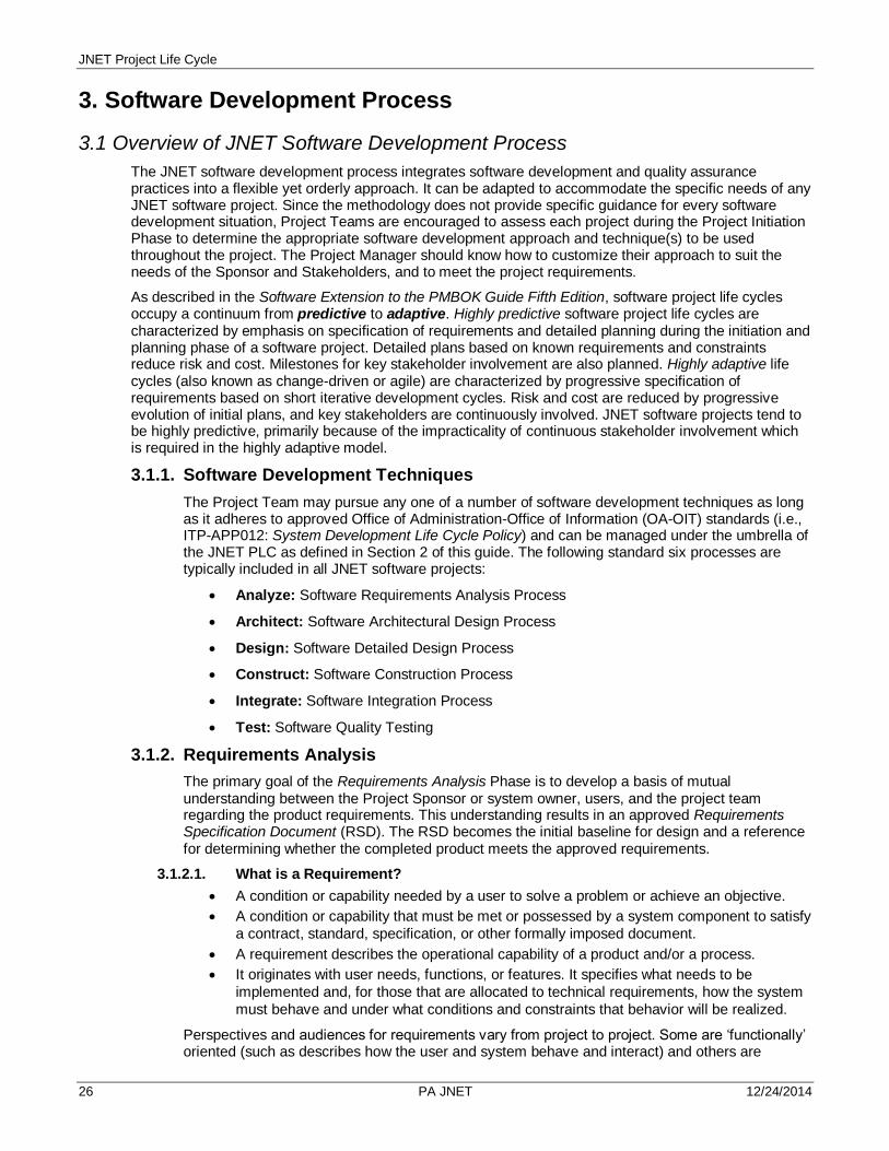
3. Software Development Process
3.1 Overview of JNET Software Development Process
The JNET software development process integrates software development and quality assurance practices into a flexible yet orderly approach. It can be adapted to accommodate the specific needs of any JNET software project. Since the methodology does not provide specific guidance for every software development situation, Project Teams are encouraged to assess each project during the Project Initiation Phase to determine the appropriate software development approach and technique(s) to be used throughout the project. The Project Manager should know how to customize their approach to suit the needs of the Sponsor and Stakeholders, and to meet the project requirements.
As described in the Software Extension to the PMBOK Guide Fifth Edition, software project life cycles occupy a continuum from predictive to adaptive. Highly predictive software project life cycles are characterized by emphasis on specification of requirements and detailed planning during the initiation and planning phase of a software project. Detailed plans based on known requirements and constraints reduce risk and cost. Milestones for key stakeholder involvement are also planned. Highly adaptive life cycles (also known as change-driven or agile) are characterized by progressive specification of requirements based on short iterative development cycles. Risk and cost are reduced by progressive evolution of initial plans, and key stakeholders are continuously involved. JNET software projects tend to be highly predictive, primarily because of the impracticality of continuous stakeholder involvement which is required in the highly adaptive model.
3.1.1. Software Development Techniques
The Project Team may pursue any one of a number of software development techniques as long as it adheres to approved Office of Administration-Office of Information (OA-OIT) standards (i.e., ITP-APP012: System Development Life Cycle Policy) and can be managed under the umbrella of the JNET PLC as defined in Section 2 of this guide. The following standard six processes are typically included in all JNET software projects:
Analyze: Software Requirements Analysis Process
Architect: Software Architectural Design Process
Design: Software Detailed Design Process
Construct: Software Construction Process
Integrate: Software Integration Process
Test: Software Quality Testing
3.1.2. Requirements Analysis
The primary goal of the Requirements Analysis Phase is to develop a basis of mutual understanding between the Project Sponsor or system owner, users, and the project team regarding the product requirements. This understanding results in an approved Requirements Specification Document (RSD). The RSD becomes the initial baseline for design and a reference for determining whether the completed product meets the approved requirements.
3.1.2.1. What is a Requirement?
A condition or capability needed by a user to solve a problem or achieve an objective.
A condition or capability that must be met or possessed by a system component to satisfy
a contract, standard, specification, or other formally imposed document.
A requirement describes the operational capability of a product and/or a process.
It originates with user needs, functions, or features. It specifies what needs to be
implemented and, for those that are allocated to technical requirements, how the system
must behave and under what conditions and constraints that behavior will be realized.
Perspectives and audiences for requirements vary from project to project. Some are ‘functionally’ oriented (such as describes how the user and system behave and interact) and others are

JNET Project Life Cycle
____________________________________________________________________________________________________27 PA JNET 12/24/2014
‘system’ oriented (such as how and when a system responds to external stimuli, operating hardware constraints, etc.).
3.1.2.2. Types of Requirements
What is Requirements Engineering?
Requirements engineering refers to all the activities involved in discovering, detailing, testing, documenting, and maintaining requirements. It includes the activities involved in understanding the business needs and transforming those into requirements that are allocated to software.
Requirements engineering involves both modeling and managing requirements. Modeling requirements involves much human interaction, investigation, and discovery. Models can be text, graphics, or a combination of both. Models communicate the requirements needed.
Requirements management establishes and maintains an infrastructure for requirements, which allows for change, and establishes practices that ensure that the right software is being developed and that it is being built correctly. Managing requirements is more technical and mechanical, although some of the management activities, such as prioritizing requirements, require direct and heavy interaction with users.
All of the Requirements Engineering concepts represented in the graphic below are addressed in JNET’s PLC.
Written from the point of view of the users or
people who must interact with the system
User language
Describes what the user gets and does not get
Owned by the Project Customers
User Requirements User requirements models
text and diagrams, data models, workflow, scenarios
Functional requirements derived from user requirement models
Derived from user or functional requirements
or may qualify functional requirements (response time, throughput, volume)
How well the solution must do it: quality from the user’s perspective (performance, speed, usability, reliability)
The being of the software OR
Non-software related requirements such as training
Owned by the development team, approved by JNET Project Sponsor
Technical Requirements Nonfunctional requirements
o User quality attributes o System constraints
language, database, platform o System requirements
audit, security
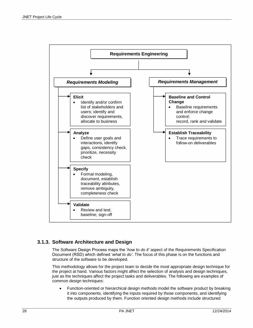
JNET Project Life Cycle
28 PA JNET 12/24/2014
3.1.3. Software Architecture and Design
The Software Design Process maps the ‘how to do it’ aspect of the Requirements Specification Document (RSD) which defined ‘what to do’. The focus of this phase is on the functions and structure of the software to be developed.
This methodology allows for the project team to decide the most appropriate design technique for the project at hand. Various factors might affect the selection of analysis and design techniques, just as the techniques affect the project tasks and deliverables. The following are examples of common design techniques:
Function-oriented or hierarchical design methods model the software product by breaking
it into components, identifying the inputs required by those components, and identifying
the outputs produced by them. Function oriented design methods include structured
Requirements Engineering
Requirements Modeling Requirements Management
Elicit
Identify and/or confirm list of stakeholders and users; identify and discover requirements, allocate to business areas
Analyze
Define user goals and interactions, identify gaps, consistency check, prioritize, necessity check
Specify
Formal modeling, document, establish traceability attributes, remove ambiguity, completeness check
Validate
Review and test; baseline; sign-off
Establish Traceability
Trace requirements to follow-on deliverables
Baseline and Control Change
Baseline requirements and enforce change control: record, rank and validate changes and follow change control processes

JNET Project Life Cycle
____________________________________________________________________________________________________29 PA JNET 12/24/2014
analysis and design. The models or used by this method include data flow diagrams, data
dictionaries, structure charts, and process specifications.
Data-oriented design methods use program structures that are derived from the data
structures. Tree diagrams are typically used to represent both the data and program
structures.
Object-oriented design methods produce a software architecture based on objects
manipulated by the system, such as the presentation layer, infrastructure, data layer, and
processing layer. The models used by this method include use case models, workflow
diagrams, business scenarios, and business rules compilation.
The chosen design technique can combine or eliminate tasks typically associated with each of the examples above.
3.1.3.1. Typical Areas of Focus within Software Design
Regardless of the chosen design technique, the following factors are typically investigated and addressed during this phase.
User Interface The user interface should be appropriate for the users, content, and operating environment of the software. Levels of interfaces for all categories of users should be addressed.
Data Model or Data Dictionary
A data model is a representation of a collection of data objects and the relationships among them. All data elements are to be included as well as detailed information about them, such as attributes, known constraints, input sources, output destinations, and known formats.
System Architecture The system architecture encompasses the technical and application architecture for software.
The technical architecture serves to provide the technical requirements (hardware, software, server configuration) for the software to work.
The application architecture serves to provide the design and layout of the requirements specific to the software system as a whole.
System Interfaces The system interface depicts how the software will interface (or interact) with other applications or systems. The following issues need to be considered when designing system interfaces:
System inputs and outputs
Method of interface
Volume and frequency of data
Platform of interfacing system
Format of data
Automatic or manual initiation of interface
Verification of data exchange
Validation of data
System Security Controls Any security or access requirements identified during Requirements Engineering phase are used to design the security controls for the software. Security controls must consider any relevant standards as specified by the Office of Administration, JNET, or regulating agency. The following need to be considered:
The users and organizations that will have access to the software and what access restrictions they will have.
Controls for the software product, such as user identification code and network access code.
Access restrictions to be applied at the system, subsystem, transaction, record, or data element levels.
Physical safeguards to protect hardware, software, or information from natural hazards and malicious acts.

JNET Project Life Cycle
30 PA JNET 12/24/2014
Capacity Planning This lays out the strategy to accommodate estimated software usage, network bandwidth, disk storage capacity, load test environment, production environment.
Conversion Planning Conversion planning is needed If the software product will replace an existing automated system. The major components to be considered include conversion procedures, an outline of the installation of new and converted data stores, conversion programming, and implementation planning.
Many factors influence data conversion including the design of the current and new system as well as the processes for data input, storage, and output. The structure of the data to be converted can limit the development of the system and affect the choice of software.
Confirmation of file integrity is required including a determination of what the output of the new system should be compared to the current system. The objective of the file conversion is the creation of new files that are complete, accurate, and ready to use. The following elements should be considered in conversion planning:
Portions of the conversion process to be performed manually
Parallel runs of the old and new systems during conversion
The function of the data in the current and new system might not always be the same and needs to be defined
The order that data is processed in the current and new system
Volume considerations such as the size of the database and the amount of data to be converted
User work and delivery schedules, time frames for reports, end-of-period procedures, or the criticality of the data might influence data conversion scheduling
Data purification tasks
Plan for the disposition of obsolete or unused data that is not converted
3.1.3.2. Prototyping
Early in the Design phase, the Project Team determines how the design will be represented to the Project Sponsor or users – through informal documentation, a prototype, or prototype iterations. Prototypes are partial models of a system. They can be built to better understand requirements and resolve requirements uncertainties, or, if they are built with a new technology that will be used for implementation, to verify the architecture and reduce technology risk. In either case, prototyping is usually an iterative process. Prototypes can be represented through ‘manual’ methods such as with paper and pens, whiteboards and markers, etc. or through review of online screen layouts to demonstrate screen content and navigational flow.
3.1.3.3. Design Reviews
Early in the Design phase, the Project Team determines the level of review of the design deliverables. The levels of review might include the following:
Peer Reviews – conducted with the Project Team Members to review each of the general
and/or detailed design deliverables to ensure that team members are in agreement to the
deliverables produced.
Walkthroughs or Structured Walkthroughs – appropriate for reviewing the technical
accuracy and completeness of general and/or detailed design deliverables and can be
conducted with various levels of formality and with different types of participants.
Critical Design Review – a formal technical review of the detailed system design to
demonstrate that the detailed system design can be implemented on the selected
platform and accounts for all software and data requirements, as well as to verify that all
design constraints (e.g., performance, interface, security, safety, resource, and reliability)
are accommodated by the proposed design.
The design reviews are focused on quality to ensure the following:
The team is following the agreed upon design approach

JNET Project Life Cycle
____________________________________________________________________________________________________31 PA JNET 12/24/2014
Adequate measures are being taken to reduce risk on technical, cost, and scheduling
issues
The performance characteristics of the design solution are acceptable
Testing will be sufficient to ensure software product correctness
The software will be maintainable
Provisions for automatic, semi-automatic, and manual recovery from hardware or
software failures are adequate
The design is:
o Complete, unambiguous, and well documented o Necessary, sufficient, and directly traceable backward to requirements and forward to
test case scenarios o Compatible with every other related specification, piece of equipment, facility, and
item of system architecture, especially regarding information flow, control, and sequencing
o Consistent with the ability of current development and user personnel o Consistent with JNET standards and guidelines
3.1.4. Software Construction
In this phase, the detailed system design is transformed into a working software product. Any hardware or software procured to support the programming effort is installed in the JNET Development (DEV) environment.
The source code is generated using the approved system design specifications. Supporting modules, including any database utilities, are coded. The source code is grouped into process able units, and all high-level language units are compiled into object code. Unit testing is performed to determine if the code satisfies the specifications and is complete, logical, and error free. Code scanning for potential Internet security vulnerabilities is also conducted during construction—as required by Commonwealth policy. The systems development management team determines which issues identified during scanning require attention, including remediation.
The operating or deployment documentation required for installing, operating, and supporting the software product through its lifecycle, is also produced in this phase. A testing strategy and detailed test cases are prepared. The acquisition and installation of the operating environment hardware and software are initiated at this point as well. The following high-level tasks should be considered, and conducted if necessary:
o Initiate procurement of hardware and software needed for the operating (Test and Production) environments
o Establish the programming environment o Write (code) programs o Conduct unit testing o Conduct code scanning for potential security vulnerabilities o Update the requirements traceability matrix o Develop test scenarios o Plan the deployment to TEST and to PRODUCTION o Produce deployment documentation and initiate deployment activities o Establish the system/integration testing environment
3.1.5. Software Integration and Testing
Software integration and testing activities focus on interfaces between and components of the software product, such as functional correctness, system stability, overall system operability,

JNET Project Life Cycle
32 PA JNET 12/24/2014
security, and performance requirements. Software integration and testing performed incrementally provides feedback on quality, errors, and design weaknesses early in the integration process.
In this phase, software components are integrated and tested to determine whether the software product meets predetermined functionality, performance, quality, interface, and security requirements. Once the software product is fully integrated, system testing is conducted to validate that the software product will operate in its intended environment, satisfies all user requirements, and is supported with complete and accurate operating documentation. After a successful system test conducted by the JNET Quality Assurance/ Test Team, either a user acceptance test (UAT) or a formal pilot test is conducted. The latter is usually conducted in the Production environment. Typical high-level tasks in this phase are:
o Conduct system and integration testing o Conduct regression testing o Report testing results o Fix bugs uncovered during testing o Update the requirements traceability matrix (optional) o Refine the deployment documentation o Prepare training materials
3.1.6. Software Implementation
Once a successful system test has been completed, preparations to place the new system into operation can begin. Most of the conversion tasks are detailed in the Deployment Document. The conversion or transition to “production” or “operational” mode is achieved using one of the following commonly-used installation strategies:
Abrupt cut-over- On a specific date, the old system is terminated and the new system is
placed into operation.
Parallel conversion – Both the old and the new system are operated for some time
period.
Location conversion – When the same system will be used at multiple locations, it is
usually converted at one location first (using either abrupt or parallel conversion). As
soon as the site has approved the system, it is farmed to the other sites.
The conversion to a production mode usually includes a validation test—i.e., running the system in a live environment, using real data. During this validation, a number of items are usually tested- (a) system performance, (b) human engineering, (c) methods and procedures, and (d) backup and
recovery. The final phase (the accreditation phase) of the CA
2 process also occurs at this point. The EISO
Team performs intrusion testing, a vulnerability assessment and penetration testing in the Production environment. An executive summary of the results is provided; the system either is accredited or a remediation plan is requested. The implementation phase typically includes user training and user documentation that guides them though the use of the new system or the old system’s new features.

JNET Project Life Cycle
____________________________________________________________________________________________________33 PA JNET 12/24/2014
3.2. Requirements Engineering
3.2.1. Description – Requirements Engineering
The objectives of Requirements Engineering include:
Capture and analyze the users’ business processes and needs.
Translate those processes and needs into formal product or system requirements.
Ensure involvement, communications, and commitment of Project Sponsors or Stakeholders who
identified the need for the project as well as JNET Project Team Members.
Participants JNET PMO
Project Sponsor(s), Stakeholders, and Representative JNET Users
JNET Managers and Team Leads (Business Office, Applications Development, Testing/Quality Assurance, JNET Applications Support)
Project Team Members
Peer Review Team (Business Office, Communications Office)
Activities / PMO Checklist
Schedule and conduct Project Team meeting to determine requirements modeling approach
Schedule and conduct requirements gathering sessions, meetings
Compile and analyze input received
Develop Requirements Specification Document (RSD)
Review with Peers (PMO, Business Office, Communications Office), the Developer(s), Tester(s), and Business Partners
Project Manager and Business Partner (if necessary) approval
Work Product(s) / Deliverables
Requirements Specification Document (RSD) (Project Team)
Application System Mock-Up (Development Team)
Optional Requirements Traceability Matrix (BA or QA Team)
Updated Project WBS/Work Plan (PMO)
Tools and Templates
Requirement Types Matrix
Requirements Specification Document (RSD) Template
Requirements Traceability Matrix Template

JNET Project Life Cycle
34 PA JNET 12/24/2014
3.2.2. Process Flow – Requirements Engineering
1 Upon approval of the Project Charter and Project Schedule, the Project Team works together to develop a requirements modeling approach for the project. The team chooses an analysis approach or technique that fits both the technical and cultural aspects of the project. No single approach is mandated; rather the decision should be based on JNET best practice, experience of the team members, and Commonwealth guidelines. The approach should consider:
The type, size, and scope of the project.
The number, location, and technical expertise of the users.
The anticipated level of involvement of the users in the data collection and analysis
process.
There are four key elements in developing a requirements analysis approach:
Determining the type of requirements that apply to the project
The Project Team reviews and completes the Requirement Types Matrix. This helps to refine
the scope of the effort as well as identify who will need to be involved in requirements
modeling.
Determining the data gathering approach and activities
1 JNET Project
Team develops a requirements
modeling approach
2 PM assigns a Project
Team Member to create a Requirements
Specification Document (RSD) based on the
agreed-upon requirements modeling
approach
3 Assigned resource gathers information needed to produce
RSD
6 PM submits the RSD
to the Key Stakeholders for
review and approval
8 Upon approval, the RSD is ‘base lined’
and Project Change
Control Process is initiated for any
change to the RSD
CA2 Initiation and
Software Design
4 Assigned resource
compiles and documents the RSD
5 Selected members of
the JNET Office review and refine the RSD
7 Project Stakeholders review and approve the
RSD
Deliverable

JNET Project Life Cycle
____________________________________________________________________________________________________35 PA JNET 12/24/2014
The team reviews the list of project participants to ensure all business and technical interests
are represented. The team also determines the type(s) of data gathering activities to solicit
and capture requirements, such as interviews, surveys, Joint Application Design (JAD)
sessions, questionnaires, or review of existing policies, procedures, training materials, and
systems.
Determining requirements analysis approach and modeling tools to be used
The team determines if any specific tools are to be employed, such as the Justice Information
Exchange Model (JIEM) tool; other data or object models; use case diagrams, text, or maps;
context diagrams; business rules; scenarios; etc.
Requirements analysis might start within this phase or in the Analysis and Design Phase. For
example, the team might decide to complete As-Is / To-Be Workflow charts within the
Requirements Phase and document them within the RSD. Other modeling techniques might
be started within the Analysis and Design Phase, such as use cases or data or object models,
and would be captured in a design document or package.
Determining how the requirements will be documented
The team determines if one or multiple documents will be used to capture user, technical,
functional, and non-functional requirements as well as the visual presentation (e.g., text
supported by graphics versus a spreadsheet). The team also determines the level at which
the requirements are captured. For example:
- High-level: provide the capability to view orders
- Low-level: orders are grouped by categories: outstanding, closed, past due
2 The Project Manager assigns a Project Team Member (usually someone serving as a Business
Analyst) to create a Requirements Specification Document (RSD) based on the agreed-upon
requirements modeling approach (Step 1). The requirements document should include sections to
correlate to the types of requirements identified on the Requirements Types Matrix and can be
used as a tool during data gathering activities.
The RSD needs to be numbered in a hierarchical numbering scheme to show decomposition of
each requirement to trace it through the remaining life cycle phases (please see step 5).
3 The JNET Business Analyst conducts data gathering activities based on the agreed-upon requirements modeling approach (Step 1).
Following data gathering activities, requirements analysis might start within this phase or might start in the Analysis and Design Phase. For example, the team might decide to complete As-Is / To-Be Workflow charts within the Requirements Phase and document them within the RSD. Other modeling techniques might be started within the Analysis and Design Phase, such as use cases or data or object models, and would be captured in a design document or package.
4 The Project’s Business Analyst compiles all notes and input captured during data gathering activities into the RSD template.
5 Selected members of the JNET Business and Communications Teams participate in a thorough (peer) review of the RSD and traceability matrix. Concurrently, a review with the Developer(s) and Tester(s) is conducted.
A key consideration in reviewing requirements is to ensure they have the following ‘SMART’1
characteristics:
Specific: without ambiguity, using consistent terminology, simple and at the appropriate level of detail.
Measurable: it is possible to verify that this requirement has been met. What tests must be performed, or what criteria must be met to verify that the requirement is met?
Attainable: technically feasible. What is your professional judgment of the technical “do-ability” of the requirement?
Realizable: realistic, given the resources. Do you have the staffing? Do you have the skill? Do you have access to the development infrastructure needed? Do you have access to the run-time infrastructure needed? Do you have enough time?
Traceable: linked from its conception through its specification to its subsequent design, implementation and test.

JNET Project Life Cycle
36 PA JNET 12/24/2014
1Mannion and Keepence, 1995
7 The Project Manager submits the RSD to the Project Sponsor/Key Stakeholder Business Partners for review and approval.
8 Upon approval, the RSD is considered base lined. From this point forward in the project, Change Control procedures are followed to add, significantly change the scope or meaning of, or delete requirements. Please refer to the Project Execution and Control Phase for further details on Change Control.
3.3. Software Design
3.3.1. Description – Software Design
The objectives of Software Design include:
To model how the software products will be built to satisfy the identified requirements.
To communicate software design information to facilitate system construction decisions and
planning.
To present the software system into design entities and describe the properties and relationships
among those entities.
Participants JNET PMO
Project Stakeholders
Project Team Members
Activities / PMO Checklist
Initiate the CA2 Process
Determine analysis and design approach, deliverables to be produced and levels of review of the deliverables
Work with the Application Development Manager to re-assess developer resource requirements and work-effort estimates
Work Product(s) / Deliverables
Design Package (Architecture and/or Development Team)
Optional System Prototype (Application Development)
Enterprise Data Center (EDC) Documentation
CA2 Approval to Proceed to Certification Phase
Updated Project WBS/Work Plan (PMO)
Tools and Templates
Use Case Diagram Template
JNET Design Template
SinglePoint App (for CA2)

JNET Project Life Cycle
____________________________________________________________________________________________________37 PA JNET 12/24/2014
3.3.2. Process Flow – Design
1 If the Commonwealth Application Certification and Accreditation process is required, the JNET CA
2 Coordinator will initiate the CA
2 Process.
The Project Team also conducts detailed analysis and review of the requirements and finalizes the business models. This might include:
Developing high-level process maps to help refine the understanding and expectations of the project’s impact on the business processes. ‘As-Is’ maps represent the current business situation and its existing infrastructure and constraints. ‘To-Be’ maps represent the situation as users would like it to be in some future implementation.
Matching business requirements to the prospective distributed application features. For example, identifying the business activities, business objects and their relationships that support the desired features. These are documented in a formal, high-level model. Also, determining the interaction between activities and objects to check their consistency and validate the model against the requirements.
NOTE: This task might have been completed in the Requirements Engineering Phase.
The Project Team selects a design technique that works well with JNET architectural and design standards. The software design technique should be based upon the unique aspects of the project, along with project and organizational constraints. Some of the issues to be addressed include:
How will the design be represented to the Project Sponsor or users – through informal documentation, a prototype, or prototype iterations?
Who will review and approve the design deliverables?
1 Project Team
conducts detailed requirements analysis
and review and (if necessary) initiates
CA2 Process
5 PM coordinates Design Package Review and
Approval
Construction
4 PM and AppDev Manager assign Project Team
Member(s) to produce the Design Package
Deliverable
2 Team members from
the Development staff determines what
technologies to use
3 Project Team assesses hardware and software
Needs

JNET Project Life Cycle
38 PA JNET 12/24/2014
The Project Team also addresses the issue of how the design will be documented (e.g., a single, encompassing Design Specification document as opposed to a number of files or documents referred to as a Design Package).
2 Project team members from the Application Development and Architecture staffs decide which system development technologies to use—i.e., define the application architecture. This task involves considering network technologies and making decisions as to how the systems’ data, processes, and interfaces are to be distributed among the business locations.
The task is accomplished by analyzing data and process models that might have been created during Requirements Engineering.
3 The purchase of any hardware and software must be initiated well in advance of the planned need for these products. This cannot begin, of course, until enough information about the ultimate design of the product. However, adequate time must be allotted in the Project Schedule for the selection, procurement, installation, testing and training associated with each purchased product.
4 The Project Team conducts detailed system design which might include the following based on the design technique chosen in Step 2:
Finalize user interface
Build data model or data dictionary
Build use case model
Build or update business process model
Design system architecture
Review capacity issues / develop capacity plan
Review integration issues / develop integration plan
Review conversion issues / develop conversion plan
Review operations and services issues / develop plan
Develop proof of concept / prototype
The results of the above design steps are captured or updated in a variety of files or documents which are incorporated into the Design Specification document or Design Package.
5 The PM ensures that the appropriate Project Stakeholders have reviewed and approved the
Design Specs.
2 JNET Project Team
Selects a Design Technique for the
Project
4 Project Team
Conducts Detailed System Design
3 Project Team
Develops General System Design (GSD)
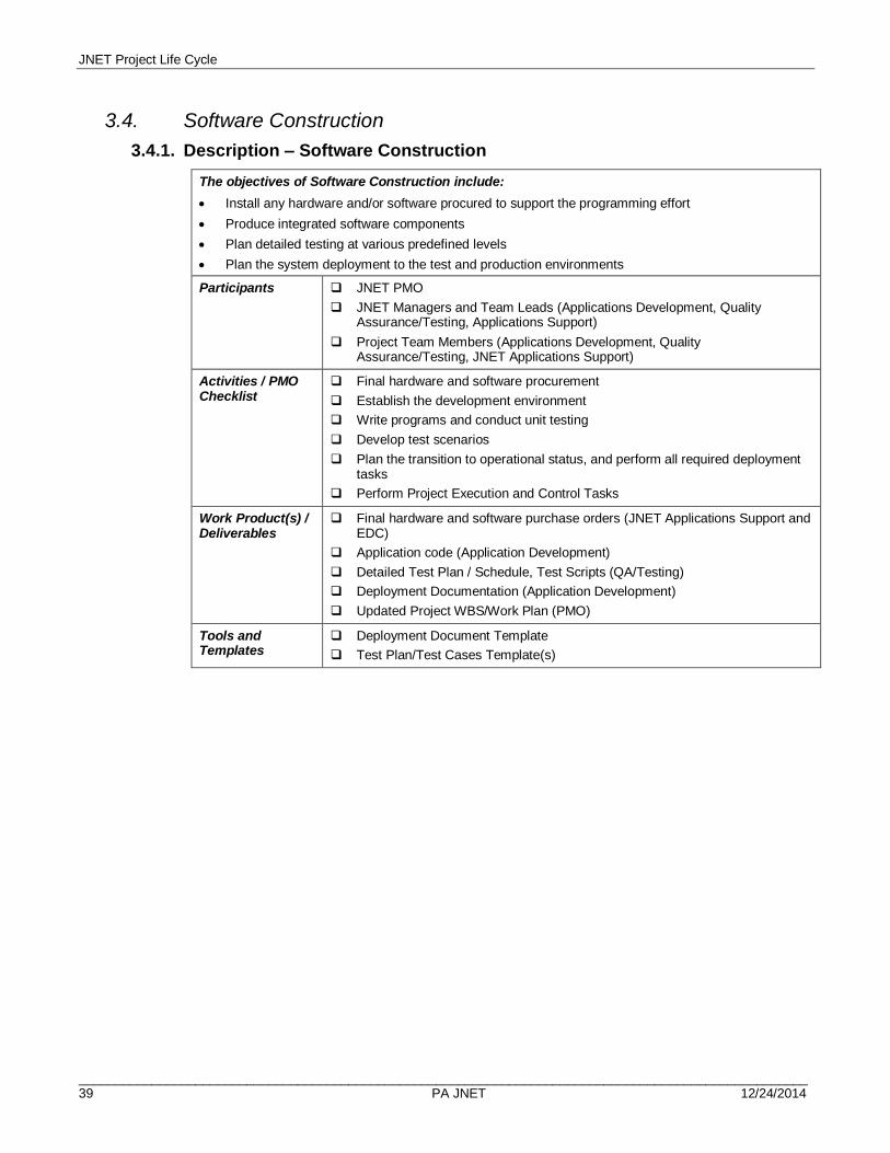
JNET Project Life Cycle
____________________________________________________________________________________________________39 PA JNET 12/24/2014
3.4. Software Construction
3.4.1. Description – Software Construction
The objectives of Software Construction include:
Install any hardware and/or software procured to support the programming effort
Produce integrated software components
Plan detailed testing at various predefined levels
Plan the system deployment to the test and production environments
Participants JNET PMO
JNET Managers and Team Leads (Applications Development, Quality Assurance/Testing, Applications Support)
Project Team Members (Applications Development, Quality Assurance/Testing, JNET Applications Support)
Activities / PMO Checklist
Final hardware and software procurement
Establish the development environment
Write programs and conduct unit testing
Develop test scenarios
Plan the transition to operational status, and perform all required deployment tasks
Perform Project Execution and Control Tasks
Work Product(s) / Deliverables
Final hardware and software purchase orders (JNET Applications Support and EDC)
Application code (Application Development)
Detailed Test Plan / Schedule, Test Scripts (QA/Testing)
Deployment Documentation (Application Development)
Updated Project WBS/Work Plan (PMO)
Tools and Templates
Deployment Document Template
Test Plan/Test Cases Template(s)

JNET Project Life Cycle
40 PA JNET 12/24/2014
3.4.2. Process Flow – Software Construction
1 If hardware and software must be purchased to meet the application system requirements, the necessary procurement activities should be performed at this time.
2 This activity involves the assembling and installation of hardware, software, communications equipment, databases and other items required to support the programming effort. Test the components to verify the operating characteristics and functionality of the hardware and software.
It is important to allot time for the project team to become familiar with any new products.
This is also a good time to review programming standards.
3 This activity involves generating source and object code, executables and scripts for the software product. Source code should be written in accordance with existing programming standards. Source code and executables should be uniquely identified and stored according to configuration management standards and procedures.
Writing programs typically includes the following:
Generating source code, executables and related scripts
Generating the physical files and database structure
Generate video screens, report generation codes and printing instructions
Generating programs to convert existing systems or data (if necessary)
Conducting preliminary testing of completed units.
2 Confirm the readiness
of the development environment
1 Perform final hardware and
software procurement activities
4 Perform Developer or
Unit Testing
8 Move the software product to the test
environment
Software Testing
3 Write program code
5 Conduct a code
review
7 Review and approve Release Request and
Deployment Documentation
(Deliverable)
6 Prepare a Detailed
Testing Plan, including Test Scenarios/Cases

JNET Project Life Cycle
____________________________________________________________________________________________________41 PA JNET 12/24/2014
4 Unit testing is used to verify the input and output for each module. Each module is tested individually and the module interface is verified for consistency with the design spec. Important processing paths through the module are tested for expected results. Error handling paths are also tested. All test results should be logged. Errors are analyzed, corrected and re-tested. The cycle is repeated until all errors have been corrected.
Whereas unit testing is generally the responsibility of the Developer, the Team Lead should be aware of the unit test results.
5 Depending on the size and complexity of the software development effort, code inspections should be conducted at successive stages of code construction. A code inspection is a static analysis technique that relies on visual examination of code to detect errors, violations of development standards, and other problems. These inspections usually are performed by an Application Team Lead, but might also be performed by experts outside the project. Ideal times for code reviews are when coding and unit testing is complete, and when the first developer-performed integration tests are complete.
6 A detailed test plan is created in this phase. The plan includes an identification of the various levels of testing that will be performed (e.g., integration and system testing, regression testing, and user acceptance testing), who is responsible for each layer of testing, how testing will be conducted, etc.
Moreover, test scenarios are created to run test scripts and scenarios based on the processes and requirements from the design package. The test scenarios might be captured in a document template or as part of a software testing toolkit.
7 The Release Request and Deployment Documents are reviewed and approved as defined by the
JNET Deployment Process.
8 Once approved, the product is moved to the JNET Test environment by the JNET Applications
Support Staff, according to the instructions in the Deployment Instructions Document.

JNET Project Life Cycle
42 PA JNET 12/24/2014
3.5. Software Testing
3.5.1. Description - Testing
The objectives of Software Testing include:
Ensuring that the system meets predetermined functional, operability, security and performance
requirements.
Providing feedback on quality, errors and design weaknesses early in the integration process.
Ensuring that the system is supported with complete and accurate operating documentation.
Ensuring that end-user communications and end-user training materials are prepared.
Participants JNET PMO
Project Sponsor(s), Stakeholders, and End Users
JNET Managers and Team Leads (Communications, Applications Development, Quality Assurance, JNET Applications Support)
Project Team Members
Enterprise Information Security Office (EISO)
Activities / PMO Checklist
Project Execution and Control Activities
Conduct System and Integration Testing
Conduct Regression Testing
Establish Acceptance Test Environment (Optional)
Conduct User Acceptance Testing (Optional)
Fix bugs uncovered during Testing
Re-Test (if necessary)
Perform source code scan using the IBM Rational AppScan tool, remediate code, and submit scan reports to EISO via the CA
2 process.
Update Requirements Traceability Matrix (Optional)
Plan a Pilot Test in Production (Optional)
Complete Training Materials
Plan End-User Communication
Refine Deployment Documentation (if necessary)
Work Product(s) / Deliverables
Internal JNET Test Report (QA/Testing)
Optional Pilot Test Survey (BA)
CA2 Certification
Training Materials (Communications/Training)
Updated Project WBS/Work Plan (PMO)
Tools and Templates
Pilot Tester Survey
Test Results Report
IBM Rational AppScan
Single Point App (for CA2)

JNET Project Life Cycle
____________________________________________________________________________________________________43 PA JNET 12/24/2014
3.5.2. Process Flow - Software Testing without Pilot
2 Developer fixes bugs
uncovered during testing, and performs source code scan for security vulnerabilities
1 Testing Team
performs testing
Implementation
3 Selected members of the Business Office
perform User Acceptance Testing
5 Review and approve Test Results Report
4 Testing Team
prepares and submits Test Results Report
Deliverable
7 Developer updates
Deployment Document
6 Trainer prepares training materials
8 PMO submits JNET
Release Request and source code scan
reports to EISO via CA
2 Process

JNET Project Life Cycle
44 PA JNET 12/24/2014
3.5.2 Process Flow - Software Testing with Pilot
1 Testing Team
performs testing
2 Developer fixes Bugs
uncovered during testing, and performs source code scan for security vulnerabilities
4 BA and
Communications Team prepare
communications to Pilot Testers
3 BA prepares and submits Pilot Test Plan for approval
Deliverable
5 BA and
Communications Team prepare online
Pilot Survey
6 BA provides the Help
Desk Staff with information needed to support Pilot Testers
7a Trainer prepares
training materials and trains Pilot Testers
9 Communications
Team sends communication to
Pilot Testers
7 Developer Updates
Deployment Document
Implementation
8 PMO submits JNET
Release Request and source code scan
reports to EISO via CA
2

JNET Project Life Cycle
____________________________________________________________________________________________________45 PA JNET 12/24/2014
1 System testing is conducted in the JNET Test environment, using test cases and the methodology described in the System Test Plan. The results of each test are recorded, and upon completion, included as part of the project test documentation stored in Star Team..
When errors are discovered, the test team leader determines the severity of the error and the necessary subsequent action. If the errors are severe, the team leader can recommend suspension of system testing until corrections are made.
2 If appropriate, minor problems can be corrected and regression tested by the Developer(s) within the time allotted for the System Test. As soon as internal testing by the QA/Test Team is completed, the Developer can perform a source code scan using the IBM Rational AppScan tool to detect any potential vulnerabilities. After the final code scan, submit the required reports for review by EISO in the CA
2
process.
3 User representatives—in many cases, these are members of the JNET Communications/Training Staff or Business Analysts/Subject-Matter Experts—participate in testing from the system owner perspective. The focus is on whether the system meets all established business and functional requirements.
If a Pilot Test is to be conducted, the Project’s Business Analyst (BA) prepares and submits a Pilot Test Plan for approval.
4 Prepare a formal Test Report. Summarize the test procedures executed, any problems that were detected and corrected, and the projected schedule for correcting any open problem reports.
If a Pilot Test is being conducted, the Communications Team and Business Analyst prepare communication to the Pilot Testers
5 The Testing Lead and Application Development Manager will review the Test Report and recommend (a) approval to proceed; or (b) approval to proceed after additional system corrections made or additional testing take place.
If a Pilot Test is being conducted, the Communications Staff and Business Analyst prepare the online Survey Form that will be used for recording survey results.
6 At this point, the Trainer will know the new system features and functions well enough to prepare training materials. Since the system implementation schedule should be established at this point, the Training Team can also start to schedule training sessions (if applicable).
If a Pilot Test is being conducted, the Business Analyst or JNET Trainer provides the JNET Help Desk with information it needs, including formal training (if required). The JNET Trainer will prepare and delver training to the Pilot Testers
7
The Developer updates Deployment Documentation.
7a If a Pilot Test is being conducted, the Training Team will prepare training materials and delver training to the Pilot Testers.
8
The PM submits a New JNET Application Release Request to move the new application system into the Production environment (ref. Star Team: JNET Document Library – Configuration and Change Management Templates – Production Release Process Artifacts – Release Management Plan_v1.0.docx)
The PM also asks JNET’s CA2 Coordinator to submit the source code scan reports to EISO.
9 If a Pilot Test is being conducted, the Communications Team will distribute a notice to the Pilot participants, the Help desk Staff and other stakeholders.

JNET Project Life Cycle
46 PA JNET 12/24/2014
3.6. Software Implementation
3.6.1. Description - Implementation
The objectives of Software Implementation include:
Ensuring that everyone who must be involved in the system installation activities are identified and
informed in advance of his or her role, as well as the target installation date(s).
Ensuring that all appropriate software quality checks have been performed and that the software is
“production-ready.”
Ensuring that an appropriate, clear communication about the software implementation is made to the
JNET user community.
A trouble-free, quick, non-disruptive installation in the JNET PROD environment.
An operational system that meets all the functional and non-functional requirements that were
established during the Requirements Engineering Phase.
Ensuring that web applications are fully accredited by the Commonwealth Application Certification
and Accreditation Process (CA2)
Participants JNET PMO
Pilot Testers (Optional)
Project Sponsor(s), Stakeholders, and End Users
JNET Managers and Team Leads
Project Team Members
EISO
PM Activities Checklist
Coordinate CA2 accreditation phase activities
Prepare and distribute a Release Request (and supporting Deployment Documentation)
Provide Deployment and Support Staff with Suggested Verbiage for End-User Communication
Prepare and Send Notice to JNET Users and Technical Partners
Install Software in the Production Environment
Validate System Operability
OPTIONAL: Conduct a Pilot Test
Work Product(s) / Deliverables
Deployment Documentation (Application Development)
CA2 Accreditation (EISO)
New JNET Application Release Request (PMO)
Communication to Pilot Testers and/or all JNET Users (Communications)
Operable System in the Production Environment (IT Staff)
OPTIONAL Pilot Test Survey and Pilot Test Results Report (BA)
Updated Project WBS/Work Plan (PMO)
Tools and Templates
OPTIONAL: Pilot Tester Survey
Release Management Plan, v.1.0 (ref. Star Team -JNET Document Library – Configuration and Change Management Templates – Production Release Process Artifacts)
Deployment Instructions/Document
Single Point System (for CA2 activities)

JNET Project Life Cycle
____________________________________________________________________________________________________47 PA JNET 12/24/2014
3.6.2. Process Flow – Software Implementation
1 The EISO Staff conducts web and host scans on the application running in the Test/Staging environment. They either pass the application to the CA
2 Finishing Phase or ask the JNET Staff to
review and respond to vulnerabilities uncovered by the scanning tools.
2 For new JNET Application System implementations or to initiate pilot testing of new application systems, the Project Manager completes and submits Release Request using the JNET New Application Release Request template. (Ref. Star Team - JNET Document Library – Configuration and Change Management Templates – Production Release Process Artifacts – Release Management Plan_v1.0.docx). The PM must ensure that all applicable items on the Release Request Checklist have been completed.
3 After the Release Request is approved and the release scheduled, the software changes are installed in the JNET Production environment according to the instructions in the Deployment Documentation.
The integrity and quality of the installed software product is verified by executing the installation tests defined in the Deployment Documentation. The test is designed to validate all functions of the software product. If the software product being installed is a modification to an existing system, all remaining functions and code that might have been affected by the new software should be tested. At a minimum, the following should be tested:
Security Functions
Integration with current software
Interfaces with other systems
2 PM prepares and submits a Release
Request for either a new application
system or a pilot test
3 Deploy the System Components to the JNET Production Environment and
Confirm Operability
4 Optional Pilot Testing
BA monitors pilot
testing and reports results
5 Optional Pilot Testing
Reach decisions
about modifying the system and go-live
date
6 Go-Live
Communications
Team informs JNET Users of System
Availability
1 EISO passes the
application through the CA
2 accreditation
review phase to the finishing phase.

JNET Project Life Cycle
48 PA JNET 12/24/2014
Any problems should be documented in a Trouble Ticket and forwarded to the appropriate resources for corrective action.
4 If a Pilot Test has been planned, The BA or Communications Team can notify the Pilot testers to start testing system functionality. The BA monitors the testing and reports results to the Development Team.
5 Based on pilot testing results, decisions about modifying the system prior to go-live are reached.
6 Once a go-live date is agreed to, the Communications Team informs all JNET users of the system’s availability, training and reference resources, etc.

JNET Project Life Cycle
____________________________________________________________________________________________________49 PA JNET 12/24/2014
4. Service Oriented Architecture (SOA) based Development Process
4.1. Overview of JNET SOA Based Standards and Policy
The primary objective of this section is to describe the process that is used to create new information exchanges via web services in the service oriented architecture. Historically, JNET message exchanges have been unique agency-to-agency transfers of information designed to meet a specific business need. However, JNET has adopted Service Oriented Architecture (SOA) which creates readily re-usable data exchanges.
SOA is an industry architectural pattern that formalizes the development of information exchanges, primarily in the form of web services. More importantly, SOA bases message exchanges on real life business practices. Rather than develop unique technology or information exchanges, SOA architecture focuses the development and deployment of services on real-world problems and needs. When services are built with an eye towards the needs of agencies and practitioners in the field, services take a more practical, business oriented, and most importantly, reusable form.
In addition to SOA, JNET has adopted the National Information Exchange Model (NIEM) and Global Reference Architecture (GRA). GRA standardizes the development and documentation of information services within the justice community. A web service built to GRA specifications will have a common documentation and design that easily facilitates sharing with external partners. NIEM predicates that all data contained within a service or exchange is consistent with national standards. All NIEM exchanges leverage these same codes, allowing for easy re-use between agencies.
Service oriented architecture is not the same as web services, however, web services are an instantiation of SOA with SOAP and Web services Description Language (WSDL). Typically, JNET uses web services as a major component of SOA.
JNET has developed JNET Web Service Security Policy documentation to ensure that the use and consumption of JNET messaging and services is secure and meets Commonwealth and JNET standards. Agencies wishing to utilize JNET's SOA are required to adhere to JNET's Web Service Security Policy when consuming or producing JNET-based services. A copy of this document is available in Star Team
by following this link: WebServicesSecurityPolicy.doc
4.2. Overview of JNET SOA Based Development Process
There are three perspectives of SOA: Service Requestor, Data Provider, and Service Agency. In some cases, JNET performs the role of one, two, or all three services. This JNET SOA lifecycle will describe the development process from all three perspectives. The following diagram will display the relationships between the three perspectives.
JNETData Provider Service RequestorService Service
4.2.1. Service Requestor
A service requestor is any organization that needs a service to obtain data. A service requestor can be another commonwealth agency, a business partner agency, or a contract agency authorized to receive data transferred by the state. A service requestor initiates a service request in writing using the JNET Web Service Request Form.

JNET Project Life Cycle
50 PA JNET 12/24/2014
4.2.2. Data Provider
A data provider is any organization that holds data and is willing to share that information with another organization. Data providers hold the data in a database or repository. The providers may be obligated to share certain data elements with other agencies as part of their ordinary business processes. Some of them may provide a web service to share that data. If they do not have a web service, JNET will have to create a web service to transfer the data.
4.2.3. JNET as a Service Provider
JNET serves as a service discovery agency when it brokers data transfers between two organizations. Currently it is rare that an agency that provides data has a web service and can directly supply the service to the requestor. In cases where JNET provides the service, it acts as a broker rather than a discovery agency. JNET brokers the requests and provides the data from the providers. In some cases, JNET owns the data and provides a service to other systems and in some cases JNET makes it available a user interface.
Criminal justice agencies rely on JNET to bridge the information gap between agency data needs and provider resources. JNET will either provide a web service for transactions or provide endpoints for customers who use web services to request and receive information. Internal services refer to the condition where customer requests JNET to build a web service to provide data. External services refer to the condition where the customer has a web service and needs JNET to provide a secure endpoint. Negotiations during the Project Qualification phase will determine the customer needs and JNET’s response to those needs. JNET operates as an SOA Competency Center and evaluates project requests or provider data on the merits of the proposal.
4.3. Phases
SOA projects can be considered a specialization of the normal software development process (ref. Section 3, above). The main difference is the introduction of a Service Model. In the traditional SDLC, the system is viewed from two aspects; a business model in the form of requirements and use cases and a technology consisting primarily of design documents.
Business Model Technology Model
SOA introduces the concept of a Service Model that bridges the gap between the Business Model and the Technology Model.
Business Model Service Model Technology Model
In GRA, the Service Model is in the form of a Service Specification Package (SSP). The SSP is a defined set of artifacts in a structured zip file. The GRA SSP specification defines many required and optional artifacts which can be found here: GRA Service Specification Guideline. The major artifacts that should be tracked in the project are listed in the table below:
Artifact Description
Service Description Document (SDD)
The SDD provides a comprehensive description of the service. It contains the following sections:
1. Service Overview 2. Business Scenarios 3. Service Interoperability Requirements 4. Additional Information 5. Service Model
Business Process Model (BPM)
Document showing the business process model for the service. Ideally this would be in the form of Business Process Modeling Notation (BPMN) however

JNET Project Life Cycle
____________________________________________________________________________________________________51 PA JNET 12/24/2014
a Visio cross-functional flow diagram is sufficient.
Information Exchange Package Definition (IEPD)
The IEPD contains the data model and NIEM schema for the service payload. Some SOA projects will reuse an existing IEPD others will require new IEPD development.
Web Service Description Language (WSDL) file
A machine readable XML representation of the service interface used by development tools to create the web service and web service clients.
Since the SSP bridges the Business and Technology Model, its development spans the Requirements Engineering and Software Design phases of the normal JNET Software Development process. The following sections are a supplement to Section 3 detailing the additional processes and deliverables for SOA projects (click here).
4.3.1. Requirements Engineering
The objectives of Requirements Engineering include:
Capture and analyze the users’ business processes and needs.
Translate those processes and needs into a service process model and information model.
Participants Service requester, Data Owner, Stakeholders, and Representative JNET Users
Business Analyst
Systems Analyst
Data Architect
Activities / PMO Checklist
Schedule business process and information modeling sessions with Business Analyst, Data Architect, Systems Analyst, data owner, service requester and other stakeholders as required.
Compile and analyze input received
Develop first half of Service Description Document (SSD)
Project Manager and Business Partner (if necessary) approval
Work Product(s) / Deliverables
Service Description Document - Sections 1 and 2
Business Process Model
IEPD - Data Element Dictionary
IEPD – Domain Model
Tools and Templates
Service Description Document (SDD) Template
4.3.2. Software Design
The objectives of Software Design include:
Translate the service business and information model into a WSDL and XML Schema.
Translate those processes and needs into a service process model and data model.
Develop the system architecture for the service solution.
Develop detailed design documentation for the webMethods and DataPower modules.
Participants Data Architect
Business or Systems Analyst
Lead Developer

JNET Project Life Cycle
52 PA JNET 12/24/2014
Activities / PMO Checklist
Data Architect completes WSDL and Schema for web service interface.
Data Architect and Systems Analyst complete SDD and SSP
Conduct SSP Review with team.
Develop Architecture Design
Review Architecture Design with team.
Develop Detail Design for webMethods and DataPower
Review Detail Design with team.
Work Product(s) / Deliverables
Complete SDD
Web Service Description Language (WSDL)
Complete IEPD (schema and mapping document)
Servicing Implementation Definition Document (SIDD)
Service Specification Package (SSP)
Architecture Design Document
Detailed Design Document (webMethods, DataPower)
Tools and Templates
Service Description Document (SDD) Template
4.3.3. Software Construction, Testing and Implementation
The software construction, testing and implementation phases mirror the normal software development process in section 3.1.4 through section 3.1.6 above. Sections 4.4.1 through section 4.4.3 (below) detail the steps for the
system development process for the SOA software development.
4.4. Configuration Differences
There are three (3) primary configuration differences managed by JNET. 1. Business Partner requesting information from JNET 2. Business Partner submitting information to JNET 3. JNET Provided Web Services User Applications
The following diagram depicts the three (3) configurations listed above

JNET Project Life Cycle
____________________________________________________________________________________________________53 PA JNET 12/24/2014
JNET
PA MAN Firewalls
External Business Partner
Requesting information
(Inactive)
Internal Business Partner
Requesting information
External Business Partner
Providing information
(Unused)
Internal Business Partner
Providing Information
Web Service
Web Service
Web Service
DataPower
Appliance
Web Service
Web Service
4.4.1. Business Partner Requesting Information
Business partner who needs information provided by JNET will make a request for data through a JNET web service using either the Event Message/Web Service Request Form (to use existing web services) or the New Event Message/Web Service Request Form (to ask JNET to develop a new web service). See diagram below. The steps outlined here assume that the request if for JNET to build a new web service.
1. Business partners request data through the JNET New Web Service Request Form. JNET senior management and staff will use the Web Service Request Form to consider the request. Some business partners are Commonwealth agencies and some business partners are outside of the Commonwealth.
2. If the requesting business partner is not a member of the Commonwealth, JNET Management may have to analyze the business needs of the external agency and determine if they are entitled to the information they are requesting. Alternatively, if the external entity is a third-party vendor for a qualified agency, JNET’s legal counsel may have to evaluate the proposal before the project starts. If that is the case, additional policy rules and approvals may be required before the project starts.
3. If the project qualifies, a JNET Project Manager will be assigned who will initiate contact with the data provider and set up a meeting to discuss the project. The data source provider will consider the project and evaluate the impact of the project and timetable against its resources. The JNET Business Analyst will begin collecting high- level business requirements. The process time decreases if the data provider has already agreed to the project objectives through prior engagement.
4. The Project Manager will begin the project and assemble the resources to complete the project initiation (ref. Section 2.2, above). He or she will provide the JNET Web Service Policy documents to the requesting business partner.
5. The Project Manager, with the assistance of the JNET Executive Director will work with the data provider to reach an agreement for the data exchange with the requestor. If there is a policy change, the Executive Director will work with the legal department to create any new policy or establish any Service Level Agreement.

JNET Project Life Cycle
54 PA JNET 12/24/2014
6. The Business Analyst will define and document functional requirements and business rules. During the requirements gathering, the Business Analyst will also review the provider’s data and determine if JNET could provide additional services to other agencies. The Systems Analyst will create technical requirements. The Systems Analyst will work with the business partner to identify the relationships and mapping. The Analysts will complete the first half of the SDD.
7. Once the business requirements (functional and business logic) and the technical requirements (system) are completed and approved, the JNET Application Support Manager will work with the Data Architect to determine the best method to connect the data source to the data requestor. The Data Architect will complete the Service Design Document including the WSDL to make the Service Specification Package. The JNET Application Support team will complete an Operational Impact Analysis to determine the level of effort needed to achieve the infrastructure goals of the project.
8. The JNET Application Development Team (webMethods and DataPower Developers) will create the design document. Using the figure below, the Application Development Team will evaluate the requesting agency’s current condition and offer a solution.
Web Service
Inquiry Event Based
Synchronous Asynchronous (Request/Reply)
JNET builds the Web ServiceJNET builds the Web Service to Receive Request and
Business Partner builds Web Service to Receive Reply
Business Partner builds Web Service
9. If the business partner needs a synchronous inquiry, JNET will build the web service once the design document and policy have been completed and approved. The business partner will have to create a web service consumer. If the business partner needs an asynchronous inquiry, JNET will build a web service to receive the request and the business partner will have to build a web service to receive the reply. If JNET provides the information through an event message, the business partner will build the web service. The Data Architect will create an architecture design document
10. During this process, the JNET Project Manager may have to clarify staff workload expectations between all parties. The PM will also work with the internal business partner to get work status reports. Once the business partner sets up their endpoint, JNET will configure the DataPower Appliance to connect to their endpoint and pass the information from the web service to the external agency. JNET may also transform the message for the endpoint.
11. JNET and the business partner will finish building the required web service components and test the design in the Test Environment. The Data Architect will create the procedure for configuring the DataPower appliance in Test and Production
12. Once all testing is complete, JNET will promote the web service to the Production Environment and complete production checkout testing. The Project Manager will advise the data provider(s) and service requestor agency of the deployment (ref. Section 3.6, above).
13. The Project Manager will close the project (ref. Section 2.4, above).

JNET Project Life Cycle
____________________________________________________________________________________________________55 PA JNET 12/24/2014
Web Service Request Form
Contact Data Provider
Assemble Resources
Architectural Design Document: Security Policy
Security Samples
Web Service Definition Language
Policy Documents
Service Level Agreements
Managed Services - Lite
Firewall policies
Data Architect Creates Design Document
[Qualified project?] No [end]
Yes
No [end]
Yes[Data Source approves?]
Analysts collects requirements
Data Elements:
Source data elements mapping
Source data endpoints
Destination data elements mapping
Operational Analysis Network diagram
Web Service Development
External HTTPS URL
External Certificate Signing Request
Signed Certificate
Configure DataPower Appliance
End to End Testing
Production Deployment
Qualified External Agency
Requesting Agency Creates Endpoint
Figure 1 –Business Partner Requesting Information
4.4.2. Business Partner Providing Information
There are two conditions under which a business partner provides information: (a) a business partner has information and they offer it to JNET or (b) JNET seeks the data provider and makes a request for the data. Regardless, JNET will create a web service to transfer the data.
1. JNET Management will evaluate the data from the business partner and will agree to build a web service to obtain the data. If this is from a request on behalf of another agency, JNET will work with both agencies to exchange data and follow the steps in 4.4.1 and 4.4.2. (see above).
2. If the project qualifies, a JNET Project Manager will be assigned who will contact the data provider and set up a meeting to discuss the project. If the provider agency already has a web service, the JNET office will work with them to connect to the DataPower appliance. The

JNET Project Life Cycle
56 PA JNET 12/24/2014
data source provider will consider the project and evaluate the impact of the project and timetable against its resources. If the data provider has already agreed to the objectives of the project through a prior engagement, the project can skip this step. The JNET Business Analyst will analyze the data and determine which connected agencies would benefit from the data.
3. If the project involves an external provider, JNET’s legal counsel may have to evaluate the proposal before the project starts. If there is a policy change, the executive director will work with the legal department to create any new policy. The additional policy rules and approval may be required before the project formally starts.
4. The PM will begin the project and assemble the rest of the resources to complete the project initiation. The Business Analyst will create functional requirements. During the requirements gathering, the BA will also include the analysis of the provider’s data and advise the team members of additional services to other agencies.
5. The data architect will provide the Web Services Security Policy document to the provider business partner, if this was not included in a prior meeting.
6. The PM, with the assistance of the Executive Director, will work with the data provider to reach an agreement for the data exchange. If there is a policy change, the executive director will work with the legal department to create any new policy or establish any Service Level Agreement (SLA). Once the policy has been completed and approved, the PM will engage the JNET team to begin analysis. The Business Analyst will assist the Data Architect to develop first half of Service Description Document (SSD).
7. The JNET Application Support Team will complete an Operational Impact Analysis to determine the level of effort needed to achieve the goals of the project. The application support team will work with the Data Architect to determine the best method to connect the data source to the data recipient. The Systems Analyst will work with the business partner to identify the relationships and mapping.
8. The Business Analyst and the Systems Analyst will build their requirements. Once the requirements (Functional, Technical, and Business Logic) are completed and approved, the data architect will complete the Service Design Document including the WSDL to make the Service Specification Package (SSP). The Data Architect will also create an architecture design document.
9. Once the network diagram and all the planning documentation and have been completed, approved, and handed off to the web service development team, they will create the design document. Using the figure below, the application development team will evaluate the requesting agency’s current condition and offer a solution.
Web Service
Inquiry Event Message
JNET builds the Web Service to JNET WSDLBusiness Partner builds Web Service to their standard
10. If JNET is requesting information from a web service provider, JNET will build a web service to the provider agency’s standards. If the provider sends information through an event message, JNET builds the web service to JNET standard. The Application Developers will use the web services WSDL to create a web service to accept the information. JNET will either send the data forward to other business partners who have requested the data or display that information in a user interface. The data architect will create the procedure for configuring the DataPower appliance in Test and Production.
11. JNET and the business partner will finish building the required web service components and test the completed software in the test environment.

JNET Project Life Cycle
____________________________________________________________________________________________________57 PA JNET 12/24/2014
12. Once all testing is complete, JNET will promote the web service to the production environment and complete Production checkout testing. The Project Manager will advise the provider agency of the deployment (ref. Section 3.6).
i. The Project Manager will close the project (ref. Section 2.4).
Data Provider offers Information
Analyze Data Provider
Assemble Resources
Architectural Design Document:
Security Samples
Policy Documents
Web Service Definition Language
Data Architect Creates Design Document
[Qualified project?] No [end]Yes
Analysts collect requirements
Data Elements:
Source data elements mapping
Source data endpoints
Destination data elements mapping
Operational Analysis Network diagram
Service Level Agreements
Managed Services - Lite
Web Service Development
Configure DataPower Appliance
End to End Testing
Production Deployment
Provider and Requesting Agencies Create Endpoints
Business Case Created
[Existing Web Service?]
No Yes
Figure 2 –Business Partner Providing Information
4.4.3. JNET Applications using Web Services
In addition to exchanging data between business partners, JNET often develops application systems that utilize web services to make requests for data. In these instances the formal JNET New Web Service Request Form is not used. The project follows the normal software development lifecycle (ref. Section 3, above). The steps included below are only those that pertain to the development and use of web services that involve exchanges with external data sources.
1. During the project qualification phase of the project, the Project Manager may have to
analyze the business needs of the intended audience of the application and provide documentation on the relative security roles that can access the information provided. The JNET Business Office, based on the recommendation of the PM and the Security Officer, will establish the minimum user provisioning credential to access the new application. The PM,

JNET Project Life Cycle
58 PA JNET 12/24/2014
with the assistance of the Executive Director will work with the data provider to reach an agreement for the data exchange.
2. During the project qualification process, all the organizations must reach an agreement on
how to handle testing. Data provider organizations can balance their needs and test system availability to the project goals. The provider organization and JNET will work together to determine the security level and training requirements a user needs in order to access the data.
3. The Data Architect will provide the security documentation to the Application Developer. The JNET application support team will complete an Operational Impact Analysis to determine the network changes and level of effort needed to achieve the goals of the project.
4. The Application Development Manager will work with the Data Architect to determine the best method to connect the data source to the data requestor. The Application Support team will complete any updates to existing Service Level Agreements.
5. Once the requirements (System, Functional, Business Logic and User Interface) are completed and approved, the Analysts will turn them over to the application development team. The Business Analyst will assist the Data Architect to complete the first half of the Service Design Document (SDD). The Data Architect will complete the Service Design Document including the WSDL to make the Service Specification Package (SSP).The Application Development team will create the design document. The Project Manager will create the work breakdown structure to identify tasks, dependencies, and resources.
6. The Project Manager will engage the JNET team to begin any development to create the web services necessary for the application and user interface.
7. The Data Architect will create an architectural design document and create the procedure for configuring the DataPower appliance in Test and Production.
8. The Application Developers access the schema and samples that they need to begin to develop the queries and web services that provide the functionality. The data owners will provide documentation on relationships and mapping schema to JNET. WebMethods Developers will begin query development to obtain the information. If there are multiple web services necessary to achieve the objectives of the project, the Application Development Team will aggregate the web services for the user interface.
9. Once the Developers complete their queries, they will build the web services. Additionally, they will build the Business Bean/Component and the data access object, if necessary. The Developer working on the user interface will begin integrating the request interface into the web service query and the results into the display interface.
10. The Project Manager will request an operational impact analysis from the application support manager to identify the firewalls, server, connectivity, and prepare for the necessary user security levels. If necessary, the application support team will create or update the Service Level Agreement.
11. In an ideal situation, the test environments and the production environments mirror each other for adequate testing results. This would allow a thorough test from requestor to provider and back. However, a test connection between every external organization’s test environments and JNET is often not possible.
12. In situations where it is not possible to test production systems with test records, the PM should arrange for a pilot test. This may mean that the PM gets preliminary approval for pilot testing and the Business Analyst recruits pilot users early in the project. The PM can outline expectations for both the data provider and the intended users. The goal is a realistic evaluation of a new application in a real environment. Historically, pilot testing has succeeded better in the production environment than in the test environment (ref. Section 3.5).
13. Since test records in a production environment could present problems for agencies that rely on production data for ordinary operations. JNET and the business partners should have testing agreements worked out as early as step 2, above.

JNET Project Life Cycle
____________________________________________________________________________________________________59 PA JNET 12/24/2014
14. Once all testing is complete, the Developers will schedule the Production deployment of the web service application and user interface.
15. Once pilot testing has completed, we will release the application to the approved JNET users.
Project Initiation
Contact Data Provider(s)
Assemble Resources
Create Design Document:
Architectural Design Document
Software Design Document
Security Policy
Security Samples
Web Service Definition Language
Creates Design Document
[Qualified project?] No [end]Yes
No [end]
Yes
[Data Sources approve?]
Analysts collects requirements
Data Elements:
Business, Functional, & UI requirements
Source data elements mapping
Source data endpoints
Operational Analysis Network diagram
Policy Documents
Service Level Agreements
Managed Services - Lite
Web Service Development
Configure DataPower Appliance
End to End Testing
Production Deployment
Figure 3 - JNET Web Services User Application
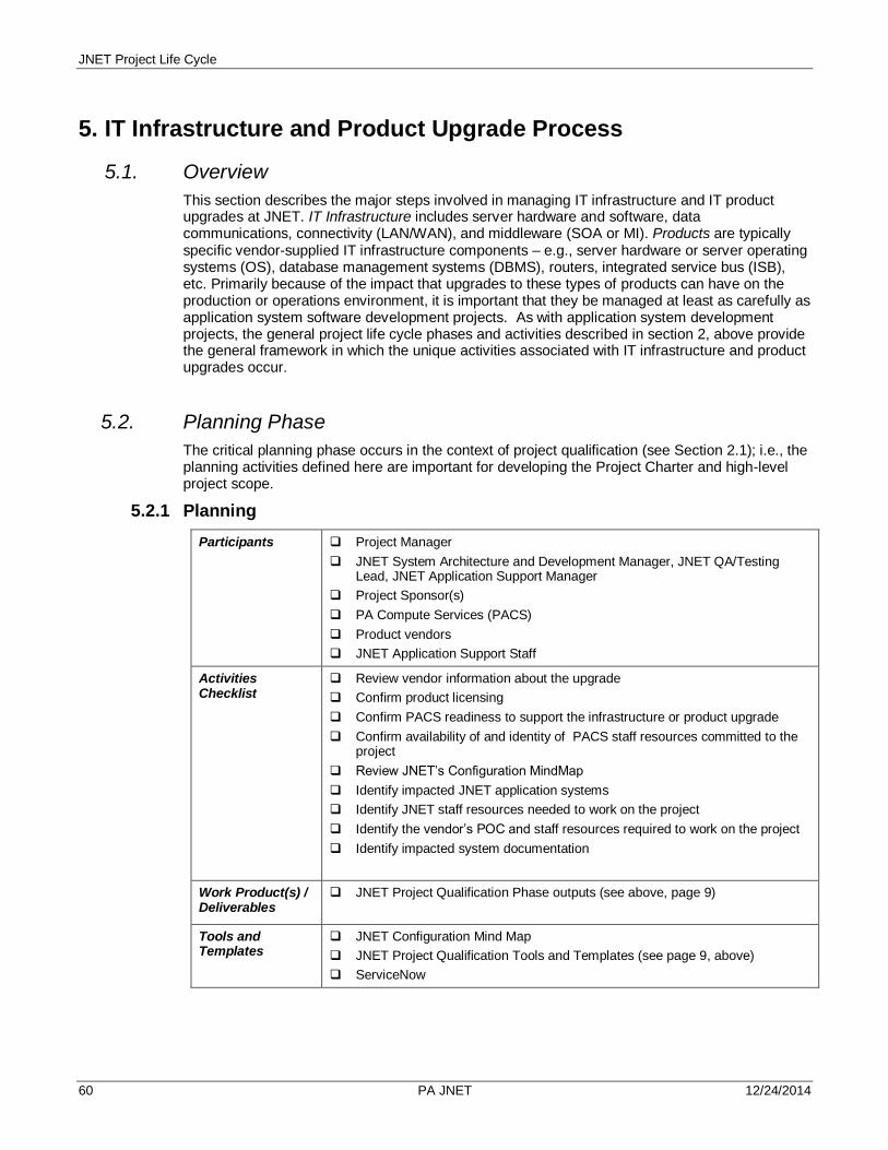
JNET Project Life Cycle
60 PA JNET 12/24/2014
5. IT Infrastructure and Product Upgrade Process
5.1. Overview
This section describes the major steps involved in managing IT infrastructure and IT product upgrades at JNET. IT Infrastructure includes server hardware and software, data communications, connectivity (LAN/WAN), and middleware (SOA or MI). Products are typically specific vendor-supplied IT infrastructure components – e.g., server hardware or server operating systems (OS), database management systems (DBMS), routers, integrated service bus (ISB), etc. Primarily because of the impact that upgrades to these types of products can have on the production or operations environment, it is important that they be managed at least as carefully as application system software development projects. As with application system development projects, the general project life cycle phases and activities described in section 2, above provide the general framework in which the unique activities associated with IT infrastructure and product upgrades occur.
5.2. Planning Phase
The critical planning phase occurs in the context of project qualification (see Section 2.1); i.e., the planning activities defined here are important for developing the Project Charter and high-level project scope.
5.2.1 Planning
Participants Project Manager
JNET System Architecture and Development Manager, JNET QA/Testing Lead, JNET Application Support Manager
Project Sponsor(s)
PA Compute Services (PACS)
Product vendors
JNET Application Support Staff
Activities Checklist
Review vendor information about the upgrade
Confirm product licensing
Confirm PACS readiness to support the infrastructure or product upgrade
Confirm availability of and identity of PACS staff resources committed to the project
Review JNET’s Configuration MindMap
Identify impacted JNET application systems
Identify JNET staff resources needed to work on the project
Identify the vendor’s POC and staff resources required to work on the project
Identify impacted system documentation
Work Product(s) / Deliverables
JNET Project Qualification Phase outputs (see above, page 9)
Tools and Templates
JNET Configuration Mind Map
JNET Project Qualification Tools and Templates (see page 9, above)
ServiceNow

JNET Project Life Cycle
____________________________________________________________________________________________________61 PA JNET 12/24/2014
5.3. Analysis Phase
The analysis activities are conducted within the project initiation framework (see Section 2.2, above). In this phase, all of the hardware, software (including application system software), communications and LAN/WAN connectivity components are thoroughly reviewed and analyzed for the upgrade’s impacts. Moreover, areas are targeted for improvement and metrics gathered to be used to assess if the target improvements have been achieved. This information is captured as technical requirements. And, if necessary, products are procured through PACS processes.
5.3.1 Analysis
Participants Project Manager
JNET System Architecture and Development Manager, JNET QA/Testing Lead, JNET Application Support Manager
PACS
Product vendors
OA Legal Staff (if required for licensing assessment)
JNET Application Support Staff
JNET Architecture and Technical Analyst(s)
Activities Checklist
Assess product licensing compliance and confirm that a sufficient number of licenses are owned.
Review and assess impacted IT infrastructure for its ability to support the upgrade
Identify and target areas for improvements
Perform a thorough risk analysis
Document technical requirements
Work Product(s) / Deliverables
Requirements Specification
Procurements
Project Initiation Phase Work Products and Deliverables (see pages 12-13)
Tools and Templates
JNET Technical Requirements Specification Template
JNET Project Initiation Tools and Templates (see page 13, above)
PACS Service Catalog
ServiceNow
5.4. Design Phase
The design phase is applicable primarily if new IT infrastructure components are being introduced that significantly affect the infrastructure design. Design phase activities are conducted within the project execution and control framework (see Section 2.3, above). The team member assigned to play the role of IT Infrastructure Architect will use the technical requirements produced in the Analysis Phase, vendor documentation, and any existing infrastructure design documents to produce detailed infrastructure design specifications. Those specs will also be provided to PACS

JNET Project Life Cycle
62 PA JNET 12/24/2014
in their required format. In addition, a detailed implementation strategy will be developed during this phase, as well as a Validation/Test Plan and Test Cases.
5.4.1 Design
Participants Project Manager
JNET System Architecture and Development Manager, JNET QA/Testing Lead, JNET Application Support Manager
PACS
Product Vendors
JNET Application Support Staff
JNET Architecture and Technical Analyst(s)
JNET QA/Tester(s)
Activities Checklist
Review technical requirements
Review existing IT infrastructure design documentation
Review existing OIT MSL Document(s)
Review vendor documentation
Produce new or revised detailed IT infrastructure design specifications
Develop upgrade implementation strategy
Develop a validation/test plan and test cases
Project execution and control activities
Work Product(s) / Deliverables
Detailed Infrastructure Design Specs (new or updated)
Upgrade Implementation Strategy
Validation/Test Plan (including Test Cases)
Project Execution and Control Phase Work Products and Deliverables (see pages 17-18)
Tools and Templates
JNET IT Infrastructure Design Document Template
Design documentation tools or templates required by PACS
JNET Test Plan and Test Cases Templates
JNET Project Execution and Control Tools and Templates (see page 18, above)
5.5 Validation Phase
Validation phase activities are conducted within the project execution and control framework (see Section 2.3, above). During this phase, the new or upgraded IT infrastructure components, as well as impacted application systems, are deployed in the JNET DEV and TEST environments, according to implementation strategy. Detailed deployment instructions are developed and documented using both the implementation strategy document and experiences gained during the actual deployments. If application systems and/or web services are impacted and must be modified, the Developers assigned to the Project make and unit test those changes n the upgraded DEV environment. The QA/Test Team then uses the Test Plan and Test Cases developed during the design phase to thoroughly test the hardware and software (including application system software) and networking components impacted by the upgrade. If test results

JNET Project Life Cycle
____________________________________________________________________________________________________63 PA JNET 12/24/2014
are positive, approval to proceed is granted. Finally, if JNET users must be notified if the impending changes, communications must be prepared at this time.
5.5.1 Validation
Participants Project Manager
JNET System Architecture and Development Manager, JNET QA/Testing Lead, JNET Application Support Manager, JNET Communications Manager
PACS
Product Vendors
JNET System Developers
JNET Application Support Staff
JNET Architecture and Technical Analyst(s)
JNET QA/Tester(s)
Activities Checklist
Review implementation strategy
Deploy infrastructure or product upgrade in JNET’s DEV and TEST Environments
Re-deploy impacted application system software and/or web services in upgraded DEV environment
Modify application systems software and/or web services as needed and unit test in the DEV environment
Produce and document detailed implementation instructions for all impacted components
Deploy modified apps to TEST
Thoroughly test/validate the changes to the infrastructure, application system software and/or web services.
Decide on date to implement in PRODUCTION
Determine if user communications are required
Project execution and control activities
Work Product(s) / Deliverables
JNET Release to TEST Request
Detailed Deployment/Implementation Plan and Instructions
Test Results Report
End-User Communications (if necessary)
Approval to implement in the PRODUCTION/Operational environment
Project Execution and Control Phase Work Products and Deliverables (see pages 17-18)
Deployment Checklist
Tools and Templates
JNET Release Request Form
JNET Deployment Instructions Template
MSL Document Template
JNET Test Results Report Template
JNET Project Execution and Control Tools and Templates (see page 18, above)

JNET Project Life Cycle
64 PA JNET 12/24/2014
5.6 Production Implementation Phase
Activities in this phase continue to be conducted under the project execution and control umbrella. Upon approval to implement the upgraded and impacted components in the operational environment, the JNET Application Support Team (and/or PACS, and/or product vendor) follows the detailed instructions developed in the validation phase to deploy to JNET’s PRODUCTION environment. The JNET QA/Test Team confirms that the implementation has been successful. If necessary, the JNET Communications Team notifies JNET Portal users and Business partners of the upgrade.
5.6.1 Production Implementation
Participants Project Manager
JNET System Architecture and Development Manager, JNET QA/Testing Lead, JNET Application Support Manager, JNET Communications Manager
PACS
Product Vendors
JNET System Developers
JNET Application Support Staff
JNET QA/Tester(s)
Activities Checklist
Submit JNET Release Request and Detailed Deployment Plan/Instructions
Schedule upgrade implementation date
Perform upgrade tasks
Perform production checkout
Notify JNET Users and Business partners (if applicable)
Project execution and control activities
Work Product(s) / Deliverables
JNET Release to PROD Request
Detailed Deployment/Implementation Plan and Instructions
Production Checkout Report
End-User Communications (if necessary)
Project Execution and Control Phase Work Products and Deliverables (see pages 17-18)
Tools and Templates
JNET Release Request Form
JNET Deployment Instructions Template
MSL Document Template
JNET Project Execution and Control Tools and Templates (see page 18, above)
5.7 Post- Implementation Review Phase
All post-implementation review activities are completed within the context of the Project Closure Activities, detailed in Section 2.4, above.

JNET Project Life Cycle
____________________________________________________________________________________________________65 PA JNET 12/24/2014
6. Glossary
Term Definition
Acceptance Criteria The criteria that a software component, product, or system must satisfy in order to be accepted by the system owner or the authorized acceptance authority.
Acceptance Testing See System Acceptance Testing
Activity A major unit of work to be completed in achieving the objective of a project. An activity incorporates a set of tasks to be completed, consumes resources, and results in work products. An activity may contain other activities in a hierarchical manner. All project activities should be described in the Project Plan.
Actor Anything that needs to interact with the system to exchange information. To the system, an actor can be a customer, user, department, organization, or another system.
Analysis See also System Analysis.
Application Enhancement See System Enhancement
Application Programs Language-based machine-readable representations of what a software process is supposed to do, or how a software process is supposed to accomplish a task.
Application System See Information System
Audit An independent examination of a work product to assess compliance with specifications, standards, quality or security requirements, contractual agreements, or other predetermined criteria.
Baseline A set of configuration items (software components and document) that has been formally reviewed and agreed upon, that serves as the basis for further development, and that can be changed only through formal change control procedures.
Baseline Plan A preliminary master project plan that includes schedule and resource assignments for the entire project.
Baseline Requirements The set of project requirements that have been approved and signed off by the system owner during the Requirements Definition Phase. The software product design is based on these requirements. The baselined requirements are placed under configuration control.
Beta Test See also Pilot Test or Validation Test.
Bug Term commonly used to describe an error or problem that has surfaced in a software program.
Bug-Fix Changes required to a program to correct a problem (or bug).
Business Analyst A systems analyst that specializes in business problem analysis and technology-independent requirements analysis.
Business Process Redesign (BPR)
Also called business process re-engineering, it is the study, analysis and redesign of fundamental business processes to reduce costs and/or improve value added to the business.
CA2 Process Commonwealth Application Accreditation and Certification—the process by
which in-house developed and purchased web-based, internet-facing application systems are assessed for security vulnerabilities.
Code Review A meeting at which software code is presented to project personnel, managers, users, or other functional areas for review, comment, or approval.

JNET Project Life Cycle
66 PA JNET 12/24/2014
Component A group of objects packaged together into one unit.
Computer-Aided Software Engineering (CASE)
The use of computers to aid in the software engineering process. May include the application of software tools for software design, requirements tracing, code production, testing, document generation, and other software engineering activities.
Configuration Control An element of configuration management consisting of the evaluation, coordination, approval/disapproval, and implementation of changes to configuration items after formal establishment of their configuration identification.
Configuration Control Board A group of people responsible for evaluating and approving/disapproving proposed changes to configuration items, and for ensuring implementation of approved changes.
Configuration Item An aggregate of hardware of software components that are designated for configuration management and treated as a single entity in the configuration management process.
Configuration Management See Software Configuration Management.
Constraint A restriction, limit, or regulation that limits a given course of action or inaction.
Cost Estimate A formal estimate of the cost to develop and support a project. Estimates should reflect all activities such as design, development, coding, distribution, service, and support of the products; staffing; training and travel expenses; subcontractor activities; contingencies; and cost for external services (e.g., technical documentation production and Quality Assurance audits and reviews).
Critical Path The sequence of dependent project tasks that have the largest sum of most likely durations. The critical path determines the earliest possible completion date of the project.
Data Flow Diagram A tool that depicts the flow of data through a system or processing performed by that system. Synonyms include bubble diagram and process model.
Data Requirements A representation of users’ data in terms of entities, attributes, relationships and rules.
Database A collection of interrelated files.
Database Administrator (DBA)
Person responsible for the database technology, database design and construction consultation, security, backup and recovery, and performance tuning.
Database Management System (DBMS)
Specialized computer software available from computer vendors that is used to create, access, control, and mange the database. Examples are Microsoft SQL Server and Oracle Database.
Deliverable A work product that is identified in the Project Plan and is formally delivered to the system owner/sponsor and other project stakeholders for review and approval.
Deployment See System Implementation.
Design See System Design.
Detailed System Design Document
A work product deliverable that describes the solution to the automation task as described by the requirements. Contains sufficient detail to provide necessary direction for writing the Program Specifications and allows developers maximum technical freedom.
Development Phase The period of time in the software lifecycle during which a software product is created from the design specifications and testing is performed on the individual software units.
Feasibility The measure of how beneficial or practical the development of an information system will be to an organization.

JNET Project Life Cycle
____________________________________________________________________________________________________67 PA JNET 12/24/2014
Feasibility Analysis The process by which feasibility is measured and assessed.
Feature Creep The uncontrolled addition of technical features to a system under development without regard to schedule and budget.
Forward Scheduling Establishes a project start date and then schedules forward from that date. Based on the planned duration of required tasks, their inter-dependencies, and the allocation of resources to complete those tasks, a projected project completion date is calculated.
Function A set of related and ongoing activities of the business. A function has no start and end; it just continuously performs its work as needed.
Functional Manager Individuals who hire and manage the day-to-day, non-project work activities of staff assigned to various functional areas of JNET, including IT Application Development, IT Application Support, the Business Office, Communications Office, Budget and Administration Office. They typically fill requests of Project Managers for Project Team members, and help oversee project activities performed by their staff members.
Functional Requirement A requirement that specifies a function that a software component, product, or system must be able to perform.
Functional Testing Testing conducted to evaluate the compliance of software product with specified functional requirements. Testing that focuses on the outputs generated in response to selected inputs and execution conditions.
Gantt Chart A simple horizontal bar chart that depicts project tasks against the calendar. Each bar represents a named project task. The tasks are listed vertically in the left-hand column. The horizontal axis is a calendar timeline.
IEPD Information Exchange Package Documentation. A written description of specific information that is exchanged between a sender and a receiver. Also includes sample XML instances and documented business rules.
Implementation Requirements
A nonfunctional requirement that supports the development and maintenance concepts and approaches in the areas of operating environment, conversion, installation, training, and documentation.
Incremental Development A software development technique in which requirements definition, design, implementation, and testing occur in an overlapping, iterative (rather than sequential) manner, resulting in incremental completion of the overall software product.
Inspection A static analysis technique that relies on visual examination of development produces to detect errors, violations of development standards, and other problems. Code inspection and design inspection are two types.
Integration Testing An orderly progression of testing in which software components are combined and tested to evaluate the interaction between them.
Interactive Analysis and Design
A development methodology that use facilitated team techniques, such as Joint Application Development or Rapid Application Development, to rapidly develop project requirements that reflect the users’ needs in terminology that the users understand. Group facilitation techniques are especially important when several user organizations have unique project requirements that are specific to their mission and goals.
Interface Requirement A nonfunctional requirement that specifies an external item with which a software product or system must interact, or that sets forth constraints on formats, timing, or other factors caused by such an interaction.
Interface Testing Testing conducted to evaluate whether software components pass data and control correctly to one another.
Joint Application Development (JAD)
A technique that complements other systems analysis and design techniques by emphasizing participative development among system owners, users, designers, and builders.

JNET Project Life Cycle
68 PA JNET 12/24/2014
Joint Requirements Planning (JRP)
A subset of JAD, it is a process whereby highly structured group meetings are conducted to analyze problems and define requirements.
Maintenance The process of supporting a software product or system after delivery to maintain operational status, correct faults, improve performance or other attributes, or adapt to a changed environment.
Methodology A collection of methods, procedures, and standards that defines an integrated synthesis of engineering approaches to the development of a work product.
Milestone An event that signifies accomplishment or completion of major deliverables during a project.
NIEM National Information Exchange Model
Nonfunctional Requirements A description of other features, characteristics and constraints that define a satisfactory system.
OA Governor’s Office of Administration. Agency of which JNET is a part.
OIT Office of Information Technology. Deputate within the Office of Administration, of which JNET is a part.
PACS PA Compute Services: a hybrid cloud-based IT infrastructure services provider for agencies under the Governor’s jurisdiction.
Performance Requirement A nonfunctional requirement that imposes conditions on a functional requirement (e.g., a requirement that specifies the speed, accuracy, or memory usage with which a given function must be performed).
PERT Chart A graphical network model that depicts a project’s tasks and the relationships between those tasks.
Phase A partition of the software lifecycle that reduces a project to manageable size and represents a meaningful and measurable set of related tasks that are performed to obtain specific work products.
Pilot Test Also called Beta Test or Validation Test, this is a test of the system running in a live environment using real data. A number of items are tested, including system performance, peak workload processing performance, human engineering, backup and recovery
PMBOK Project Management Body of Knowledge: Standards developed and published by the Project Management Institute (PMI) for the project management profession; identifies the most effective global practices in project management. In the form of a Guide, it provides a foundation that is fundamental for the universal standard practice of project management across industries, geographies and project types.
Procedure A written description of a course of action to be taken to perform a given task.
Process An ordered set of steps performed for a given purpose. Processes define or control the development of the project work products. The use of processes will ensure a consistent methodology across all platforms in producing the lifecycle deliverables.
Product See Work Product
Project A [temporary] sequence of unique, complex, and connected activities having one goal or purpose and that must be completed by a specific time, within budget, and according to specification.
Project Charter Sometimes called a Statement of Work or a Project Definition, it is a formal document that provides background information for the project request, describes the business driver, defines the project objectives, scope, project approach, major deliverables, responsibilities, and target completion dates for major milestones.
Project Folder A central repository of material pertinent to a project. Contents typically include all work products, memos, plans, technical reports, and related items.

JNET Project Life Cycle
____________________________________________________________________________________________________69 PA JNET 12/24/2014
Project Lifecycle (PLC) A methodology that governs all aspects of planning, execution and closure of projects.
Project Manager The individual with total business responsibility for all activities of a project. The Project Manager directs, controls, administers, and regulates a project.
Project Plan Either a separate document or a section of the Project Charter that describes the technical and management approach to be followed for a project. The plan typically describes the work to be done, the resources required, the methods to be used, the procedures to be followed, the schedules to be met, and the way to project will be organized. The plan includes a list of deliverable, actions required, and other key events needed to accomplish the project.
Project Team The Project Manger and all the other personnel resources assigned as the core group for a project. The project team might include representatives of partner organizations who are active participants in the project.
Prototyping A technique for developing and testing a preliminary version of the software product (either as a whole or in modular units) in order to emulate functionality without such encumbering feature as error handling, help messages, security controls, and other utilities that are not part of the design logic. This allows the project team to test the overall logic and workability of required functions and requirements meet the intended objectives. Prototyping is often used in conjunction with interactive analysis and design techniques.
Rapid Application Development (RAD)
Techniques that emphasize extensive user involvement in the rapid and evolutionary construction of working prototypes of a system to accelerate the systems development process.
Rapid Prototyping A type of prototyping in which emphasis is placed on developing prototypes earlier in the development process to permit early feedback and analysis in support of the development process.
Regression Testing Selective retesting of a software component to verify that modifications have not caused unintended effects and that the software component still complies with its specified requirements.
Requirement A condition of capability needed by a system owner and user to solve a problem or achieve an objective. A condition or capability that must be met or possessed by the software product to satisfy a contract, standard, specification, or other formally imposed documents.
Requirements Analysis The process of studying system owner and user(s) needs to arrive at a definition of system, hardware, or software requirements.
Requirements Definition Phase
The period of time in the project or software lifecycle during which the requirements for a project’s final deliverable or a software product are defined and documented.
Requirements Specification A work product deliverable that specifies the manual and automated requirements for a software product (or other project final deliverable) in non-technical language that they system owner and users can understand. Typically included are functional requirements, and non-functional requirements such as performance requirements, and interface requirements. Describes in detail what will be delivered in the product release.
Resource Leveling A strategy used to correct resource over-allocations by some combination of delaying or splitting tasks.
Risk The possibility of suffering loss.
Risk Management An approach to problem analysis that is used to identify, analyze, prioritize, and control risks.
Scope Defines the boundaries of a project—what part of the business is to be studied, analyzed, designed, constructed, implemented and ultimately

JNET Project Life Cycle
70 PA JNET 12/24/2014
improved.
Scope Creep The unexpected growth of user expectations and business requirements for a project’s final deliverable as the project progresses. The project schedule and budget can be affected by such changes.
Service Oriented Architecture (SOA)
The concept that information delivery from multiple sources is a service that can be provided either through direct user request or from a system request to distribute capabilities from different ownership domains. SOA is not limited by any specific technology. Web Services are a port of SOA using SOAP and WSDL.
Service Description Document (SDD)
A document that provides a comprehensive description of the web service and contains the following sections: Service Overview, Business Scenarios, Service Interoperability Requirements, Additional Information, and the Service Model.
SOAP The protocol specification for exchanging structured information in the implementation of Web Services in computer networks. It relies on Extensible Markup Language (XML) for its message format, and usually relies on other Application Layer protocols, most notably Hypertext Transfer Protocol (HTTP) and Simple Mail Transfer Protocol (SMTP), for message negotiation and transmission.
Slack Time The amount of delay that can be tolerated between the starting time and completion time of a task without causing a delay in the completion of an entire project.
Software Computer programs, procedures, and associated documentation and data pertaining to the operation of a software product or system.
Software Configuration Management
(1) A discipline that effectively controls and manages all modifications to a software component, product, or system. Technical and administrative processes and tools are used to identify and document the functional and physical characteristics of the configuration items, manage and track changes to those items, record and report change processing and implementation status, and verify compliance with specified requirements.
(2) A software Engineering Institute Capability Maturity Model key process that is designed to establish and maintain the integrity of the software work products throughout the system’s lifecycle.
Software Lifecycle The period of time that begins when a software product is conceived and ends when the software is retired. A network of phases and processes that function together to guide the development and maintenance of software products. Each process produces a set of deliverables as it moves through the lifecycle.
Software System A software product and the documentation, hardware, and communications needed to implement and operate the product and accomplish a specific function or set of functions. See also Information System.
Specification A document that specifies in a complete, precise, verifiable manner the requirements, design, behavior, or other characteristics of a component, product, or system.
Stakeholder Any person who has an interest in an existing or new information system. A stakeholder can be a technical or a non-technical worker.
Structured Analysis An analysis technique that uses a graphical language to build models of software products or systems. The four basic features in structured analysis are data flow diagrams, data dictionaries, procedure logic representations, and data store structuring techniques.
Structured Design A process-centered technique that transforms the structured analysis models into good software design models. A modeling tool called structure charts is used to illustrate software structure to fulfill business requirements.

JNET Project Life Cycle
____________________________________________________________________________________________________71 PA JNET 12/24/2014
System A collection of hardware, software, firmware, and documentation components organized to accomplish a specific function or set of functions.
System Development Lifecycle (SDLC) or Methodology (SDM)
The very formal and precise methodology that identifies the processes, activities, tasks, management responsibilities, and work products that are required for each software development and maintenance project. A key objective of the methodology is to provide measurable, repeatable processes to assure that project development and maintenance methodologies are consistent throughout the information systems environment.
System Enhancement Adapting an existing system to new business requirements or new design requirements. Usually initiated by system owners. Sometimes called Application Enhancement.
System Maintenance Applying upgrades or patches to the underlying production platforms on which information systems run.
System Owner The organizational unit that funds and has approval authority for a system development or system enhancement project. Typically, system owners are also system users.
System Test A test to ensure that application programs written and tested in isolation work properly when they are integrated into the total system. This test usually involves system owners, users, developers and analysts. Testing is done using test data that was previously developed by a Systems Analyst.
Systems Acceptance Test A final system test performed by end-users using real data over an extended period of time.
Systems Analyst Facilitates the development of information systems and computer applications by bridging the gap that exists between non-technical system owners and users and technical system designers and builders.
System Conversion or Implementation
The delivery of a developed and tested system into production (meaning day-to-day operation).
Systems Support The ongoing technical support for users, as well as the maintenance required to fix any errors, omissions or new requirements that may arise.
Task The smallest unit of work subject to management accountability. A task is well-defined work assignment for one or more project team members. Related tasks are usually grouped to form activities. An task is the lowest level of work division typically included in the Project Plan and Work Breakdown Structure.
Task Dependency A relationship of one task to another where the start of end date of the second task is related to the start or end date of the first task.
Test Bed An environment containing the hardware, instrumentation, simulators, software tools, and other support elements needed to conduct a test.
Test Case A set of test inputs, execution conditions, and expected results that are developed for a particular objective, such as to exercise a particular program path or to verify compliance with a specific requirement.
Test Criteria The criteria that a software component or product must meet in order to pass a given test.
Test Documentation Documentation describing plans for, or results of, the testing of a software component or product. Documents typically include test case specifications, test incident reports, test logs, test plans, test procedures, and test reports.
Test Log A chronological record of all relevant details about the execution and results of a test.

JNET Project Life Cycle
72 PA JNET 12/24/2014
Test Phase The period of time in the software lifecycle in which the components of a software product are evaluated and integrated, and the software product is evaluated to determine whether or not the requirements have been satisfied.
Test Plan A document specifying the scope, approach, resources, and schedule of intended testing activities. The plan identifies test items, the features to be tested, the testing tasks, who will do each task, and any risks requiring contingency planning.
Test Procedure Detailed instructions for the setup, execution, and evaluation of the results for a given test case.
Test Report A document that describes the conduct and results carried out for a software component or product.
Test Script As users enter test data, that data is recorded in a special type of repository as a script. Ultimately, the test script is executed against the program to test that it executes properly and also to measure the program’s response time.
Testing An activity in which a software component or product is executed under specified conditions, the results are observed and recorded, and an evaluation is made.
Total Quality Management (TQM)
Comprehensive approach to facilitating quality improvements and management within a business and its products and services.
Traceability The degree to which a relationship can be established between two or more products of the development process, especially products having a predecessor-successor relationship to one another.
Transaction Analysis A technique used to derive structured charts for a software product that will process transactions. Transaction analysis is used to divide complex data flow diagrams into smaller, simpler data flow diagrams—one for each transaction that the product or system will process. Structure charts are developed from the simple data flow diagrams. The individual structure charts for the separate transactions are then combined to form one large structure chart that is very flexible and can accommodate user changes.
Use Case A behaviorally related sequence of steps (a scenario), both automated and manual, for the purpose of completing a single business task.
Unit A separately testable element specified in the design of a computer software component. A software component that is not subdivided into other components.
Unit Testing Testing of individual hardware or software units or groups of related units. The isolated testing of each flowpath of code with each unit. The expected output from the execution of the flowpath should be identified to allow comparisons of the planned output against the actual output.
Usability The ease with which a user can learn to operate, prepare inputs for, and interpret outputs of a software product.
User The general population of individuals who use a software product or system. User activities can include data entry; read only; add, change and delete capabilities; querying; and report generations.
User Interface An interface that enables information to be passes between a user and hardware or software components of a computer system.
User Manual A document that presents the information necessary to use a software product to obtain desired results. Typically described are product or component capabilities, limitations, options, permitted inputs, expected outputs, possible error messages, and special instructions.
User Testing Two types: Functional Testing (see above) and Usability Testing which is used to uncover problems related to ease-of-use.
Validation Testing Runs the system in a live environment using real data. Also called beta testing or pilot testing.

JNET Project Life Cycle
____________________________________________________________________________________________________73 PA JNET 12/24/2014
Walkthrough An analysis technique in which a team of subject matter experts review a segment of code or documentation, ask questions, and make comments about possible errors, violations of development standards, and other problems.
Web Service The main enabling technique for SOA. Functions as middleware and as a modeling and management tool for composed business processes.
Web Services Definition Language (WSDL)
An XML format for describing network services as a set of endpoints operating on messages containing either document-oriented or procedure-oriented information. These operations and messages are described and then bound to a concrete network protocol and message format to define an endpoint. Related concrete endpoints are combined into services.
Work Breakdown Structure (WBS)
A hierarchical decomposition of a project into phases, activities and tasks.
Work Product Any tangible item that results from a project function, activity, or task. Examples of work products include process descriptions, plans, procedures, computer programs, and associated documentation, which may or may not be intended for delivery to the system owner and other project.
![WELCOME [forums.juniper.net]forums.juniper.net/jnet/attachments/jnet/SAJUG/2/1... · WELCOME . AUGUST 27TH, 2013 . Sacramento Area Juniper Users Group: #sajug](https://img.dokumen.tips/doc/110x75/5f13a7003d77ab60eb2bf121/welcome-welcome-august-27th-2013-sacramento-area-juniper-users-group-sajug.jpg)