Embed Size (px)
Citation preview

JUNE 2015
Thesis Advisor: Prof. Dr. Nadia ERDOĞAN
Faculty of Computer and Informatics
Computer Engineering Programme
Bilgisayar Mühendisliği Programı
Anabilim Dalı : Herhangi Mühendislik, Bilim
Programı : Herhangi Program
M.Sc. THESIS
Murat ÖZTÜRK
ISTANBUL TECHNICAL UNIVERSITY GRADUATE SCHOOL OF SCIENCE
ENGINEERING AND TECHNOLOGY
A DATA REPLICATION STRATEGY TO IMPROVE SYSTEM AVAILABILITY
FOR CLOUD STORAGE SYSTEMS
THIRD LINE IF NECESSARY, FIT TITLE IN THREE LINES


ISTANBUL TECHNICAL UNIVERSITY GRADUATE SCHOOL OF SCIENCE
ENGINEERING AND TECHNOLOGY
M.Sc. THESIS
Murat ÖZTÜRK
504111552
Faculty of Computer and Informatics
Computer Engineering Programme
Bilgisayar Mühendisliği Programı
Anabilim Dalı : Herhangi Mühendislik, Bilim
Programı : Herhangi Program
Thesis Advisor: Prof. Dr. Nadia ERDOĞAN
JUNE 2015
A DATA REPLICATION STRATEGY TO IMPROVE SYSTEM AVAILABILITY
FOR CLOUD STORAGE SYSTEMS
THIRD LINE IF NECESSARY, FIT TITLE IN THREE LINES


HAZİRAN 2015
İSTANBUL TEKNİK ÜNİVERSİTESİ FEN BİLİMLERİ ENSTİTÜSÜ
BULUT DEPOLAMA SİSTEMLERİ İÇİN SİSTEM ERİŞİLEBİLİRLİĞİNİ
ARTIRAN VERİ KOPYALAMA STRATEJİSİ
YÜKSEK LİSANS TEZİ
Murat ÖZTÜRK
504111552
Bilgisayar Mühendisliği Anabilim Dalı
Bilgisayar Mühendisliği Programı
Bilgisayar Mühendisliği Programı
Anabilim Dalı : Herhangi Mühendislik, Bilim
Programı : Herhangi Program
Tez Danışmanı: Prof. Dr. Nadia ERDOĞAN


iii
Thesis Advisor : Prof. Dr. Nadia ERDOĞAN ..............................
İstanbul Technical University
I ..............................
İstanbul Teknik Üniversitesi
Jury Members : Prof. Dr. Bülent ÖRENCİK .............................
Beykent University
Hava Harp Okulu
Asst. Prof. Deniz Turgay ALTILAR .............................
İstanbul Technical University
İstanbul Teknik Üniversitesi
Murat Öztürk, a M.Sc student of ITU Institute of / Graduate School of Science
Engineering and Technology student ID 504111552, successfully defended the
thesis/dissertation entitled “A DATA REPLICATION STRATEGY TO
IMPROVE SYSTEM AVAILABILITY FOR CLOUD STORAGE SYSTEMS”,
which he prepared after fulfilling the requirements specified in the associated
legislations, before the jury whose signatures are below.
STORAGE SYSTEMS” başlıklı tezini aşağıda imzaları olan jüri önünde başarı ile
sunmuştur.
Date of Submission: 4 May 2015
Date of Defense: 01 June 2015

iv

v
To my family,

vi

vii
FOREWORD
I would like to thank to my advisor Prof. Dr. Nadia Erdoğan for her technical and
intangible support during my thesis study. She was always very helpful and patient to
me. Almost every week, we had meetings on this study. Besides her
technical/theoratical knowledge, personally she is really constructive, creative and
kind person. I am extremely happy that I had a chance to work with her. I also would
like to thank to my family keeping my motivation high during this period.
May 2015
Murat Öztürk
Computer Engineer

viii

ix
TABLE OF CONTENTS
Page
FOREWORD ............................................................................................................ vii TABLE OF CONTENTS .......................................................................................... ix ABBREVIATIONS ................................................................................................... xi LIST OF TABLES .................................................................................................. xiii
SUMMARY ............................................................................................................ xvii
ÖZET ........................................................................................................................ xix
1. INTRODUCTION .............................................................................................. 1 1.1 Purpose of the Thesis ................................................................................... 3
2. RELATED WORKS .......................................................................................... 5 3. CLOUD COMPUTING ..................................................................................... 7
3.1 What is Cloud computing ? .......................................................................... 7
3.2 The Services in Cloud .................................................................................. 8 3.3 The Evolution of Cloud Computing ............................................................. 8
3.4 Cloud Formations ......................................................................................... 9 3.5 Silver Linings and Thunder Clouds ........................................................... 10
3.5.1 Advantages ............................................................................................. 10
3.5.2 Disadvantages ........................................................................................ 13 3.6 Cloud Service Models ................................................................................ 14
4. DATA STORAGE AS A SERVICE ............................................................... 17 4.1 STaaS Storage Types ................................................................................. 18
4.1.1 Structured storage................................................................................... 18 4.1.2 Block storage .......................................................................................... 19 4.1.3 Object storage......................................................................................... 19
4.2 Example STaaS Provider – Amazon S3..................................................... 21 4.3 Example STaaS Middleware – OpenStack Swift....................................... 23
4.4 Example STaaS API - CDMI ..................................................................... 23 4.5 CloudSim ................................................................................................... 25
5. STORAGE CLOUDSIM ................................................................................. 27 5.1 Architecture ................................................................................................ 27
5.1.1 User code and user interface structures .................................................. 27 5.1.2 Provided storage services ....................................................................... 28 5.1.3 Resources, resource usage and network ................................................. 29
5.2 Sequence Diagram ..................................................................................... 29 5.3 Implementation .......................................................................................... 32
5.3.1 STaaS provider models .......................................................................... 32 5.3.1.1 Internal storage models .................................................................. 34
5.3.1.1.1 Blob and blobLocators ............................................................. 34
5.3.1.1.2 Servers and hard drives ............................................................ 34
x
5.3.1.2 Object storage cloud model ............................................................ 35
5.3.2 User models ........................................................................................ 36 5.3.2.1 StorageBroker class ........................................................................ 36 5.3.2.2 UsageSequence class ...................................................................... 36
5.3.2.3 Service level aggrements ................................................................ 37 5.3.2.4 MetaStorageBroker class ................................................................ 37 5.3.2.5 Request layers ................................................................................ 38 5.3.2.6 CDMI requests ............................................................................... 39
5.3.2.6.1 Cloud discovery request ........................................................... 39
5.3.2.6.2 GET container request .............................................................. 39 5.3.2.6.3 GET object request ................................................................... 39 5.3.2.6.4 Put container request ................................................................ 40 5.3.2.6.5 Put object request – creation ..................................................... 40 5.3.2.6.6 Put object request – update ....................................................... 41
5.3.2.7 UserRequest and UserMetaRequest class ...................................... 41
5.3.3 Scenario generation ................................................................................ 42
6. SYSTEM ARCHITECTURE .......................................................................... 45 6.1 System Model ............................................................................................. 45 6.2 Disk Weighting .......................................................................................... 48 6.3 Optimum Replica Number and Replica Placement Algorithm .................. 49
7. PERFORMANCE EVALUATION ................................................................ 55 7.1 Generate Cloud GUI ................................................................................... 55
7.2 Sequence Generator GUI ........................................................................... 56 7.3 Main GUI ................................................................................................... 60 7.4 Experiments ................................................................................................ 60
8. CONCLUSION ................................................................................................. 69
REFERENCES ......................................................................................................... 71 APPENDICES .......................................................................................................... 73
APPENDIX A ........................................................................................................ 74
CURRICULUM VITAE .......................................................................................... 79

xi
ABBREVIATIONS
SLA : Service Level Aggrements
CDMI : Cloud Data ManagementInterface
STaaS : Storage as a Service
PaaS : Platform as a Service
IaaS : Infrastructure as a Service
SaaS : Software as a Service
API : Application Programming Interface
VM : Virtual Machine
DBMS : Database Management Systems
SAN : Storage Area Network

xii

xiii
LIST OF TABLES
Sayfa
Table 4.1: Comparison between Block Storage and Object Storage .................. 20
Table 4.2: Storage Prices for Amazon S3 standart storage in US ....................... 21
Table 4.3: Costs per request for Amazon S3 in US............................................. 22
Table 4.4: Traffic cost for Amazon S3 in US...................................................... 22
Table 6.1: Server-Disk pairs after sorting with sequence numbers ..................... 51
Table 6.2: Each Queue and its disks.................................................................... 52
Table 7.1: Experiment Types .............................................................................. 61

xiv

xv
LIST OF FIGURES
Sayfa
Figure 3.1 Cloud Service Models ........................................................................ 15
Figure 4.1: CDMI root container wirh multiple containers .................................. 24
Figure 4.2: CloudSim Overview ........................................................................... 25
Figure 5.1: StorageCloudSim Architecture .......................................................... 28
Figure 5.2: Sequence diagram for Storage CloudSim .......................................... 30
Figure 5.3: StorageCloudSim Class Diagram ....................................................... 33
Figure 5.4: CDMI Object, Blob and Blob Locators ............................................. 34
Figure 5.5: Server and Disk IO Limitations ......................................................... 35
Figure 5.6: Request Layers ................................................................................... 38
Figure 5.7: PutObject State Diagram .................................................................... 40
Figure 5.8: Creating user request from JAVA code ............................................. 42
Figure 5.9: XML representation of SLA of normal sequence .............................. 43
Figure 5.10: XML representation of a complete sequence ................................. 44
Figure 6.1: Failure probability definition for disk in cloud model xml ................ 45
Figure 6.2: Minimum availability definition in cloud model xml ........................ 46
Figure 6.3: Servers location definition in cloud model xml ................................. 46
Figure 6.4: Minimum availability definition in cloud model xml ........................ 47
Figure 6.5: User SLA minimum availability definition in user sequence xml ..... 48
Figure 6.6: User location definition in user sequence xml ................................... 48
Figure 6.7: Algorithm: Our strategy for replica placement .................................. 53
Figure 7.1: Generate Cloud GUI Screen............................................................... 55
Figure 7.2: Adding servers and their configuration screen................................... 56
Figure 7.3: Sequence Generator GUI Screen ....................................................... 57

xvi
Figure 7.4: Generated User Sequence file example .............................................. 59
Figure 7.5: Main Screen ........................................................................................ 60
Figure 7.6: Replica count graphic for experiment 1 ............................................. 62
Figure 7.7: Load rate graphic for experiment 1 .................................................... 63
Figure 7.8: Graphic for disk load rates as bar representation in experiment 1 ..... 64
Figure 7.9: Replica count graphic for experiment 2 ............................................. 65
Figure 7.10: Graphic for disk load rates in experiment 2 ................................... 66
Figure 7.11: Graphic for disk load rates as bar representation in experiment 2 . 67
Figure A.1: Generated Cloud file example ............................................................ 78

xvii
A DATA REPLICATION STRATEGY TO IMPROVE SYSTEM
AVAILABILITY FOR CLOUD STORAGE SYSTEMS
SUMMARY
The Cloud environment constitutes a heterogeneous and a highly dynamic
environment. The Cloud Computing provides the software and hardware
infrastructure as services using large-scale data centers. As a result, Cloud
Computing moved away the computation and data storage from the end user and
onto servers located in data centers, thereby relieving users of the burdens of
application provisioning and management and enabling them to focus on managing
of their application logic. However, failures on the data center storage nodes often
take place in cloud computing environments. As a result, the cloud environment
requires some capability for an adaptive data replication management in order to
cope with the inherent characteristic of the Cloud environment. To improve system
availability and get high fault tolerance, replicating data is a good choice. Replication
is the process of providing different replicas of the same service at different nodes. In
most of the real cloud, data replication is achieved through data resource pool, the
number of data replicas is statistically set based on history experience and is usually
less than 3. This strategy works well at most time, but it will fail at inclement times.
Replicating the data with a fixed number of its copies to multiple suitable locations
should not be an advisable choice. How to decide a reasonable number and
right/suitable locations for replicas has become a challenge in the cloud computing.
In this thesis, we present a new dynamic data replication strategy suitable for cloud
environments. Our technique provides optimum replica number and prevents the
replica number from incrementing in time. In addition, it enables the replicas to be
placed to all data center nodes in a balanced way depending on the available disk
space for a disk, expected availability of requesting cloud users, failure probability of
each node in data center servers. We also conclude that bandwidth usage can be
reduced by considering the distance between user and data center servers and
locating the replicas nearby users who requests for.

xviii

xix
BULUT DEPOLAMA SİSTEMLERİ İÇİN SİSTEM ERİŞİLEBİLİRLİĞİNİ
ARTIRAN VERİ KOPYALAMA STRATEJİSİ
ÖZET
Bulut Bilişim ortamı farklı özelliklerde olan ve oldukça dinamik bir ortamdan oluşur.
Bulut Bilişim, büyük ölçekli veri merkezlerini kullanarak yazılım ve donanım
altyapısını servisler olarak dışarıya kullanıma açmaktadır. Sonuç olarak, Bulut
Bilişim işlem ve veri depolama işini son kullanıcıdan veri merkezlerindeki
sunuculara taşımaktadır, bu sayede kullanıcıları uygulama kurulumu ve yönetimi
yüklerinden kurtarıp, kullanıcıların sadece kendi uygulamalarının mantığını
yönetmelerine odaklanmalarını sağlamaktadır. Ancak, bulut bilişim ortamlarında,
veri merkezlerinin depolama düğümlerinde sıklıkla hatalar oluşmaktadır. Sistemin
erişilebilirliğini artırmak ve yüksek oranda hata toleransı sağlamak için, verilerin
kopyasını oluşturmak iyi bir seçenektir. Kopyalama, aynı servisin farklı düğümlerde
farklı kopyalarının olmasını sağlama sürecidir. Gerçek dünyadaki bulut ortamların
çoğunda, veri kopyalama veri kaynak havuzlarıyla gerçekleştirilir, veri kopyalarının
sayısı geçmiş deneyimlere bakılarak statik olarak karar verilir ve genellikle 3’den
küçüktür. Bu strateji çoğunlukla iyi çalışır, ancak zorlu durumlarda hata verecektir.
Verilerin sabit sayıda kopyasını oluşturmak ve bunları farklı uygun lokasyonlara
koymanın tercih edilen bir yaklaşım olmaması gerekir. Mantıklı ve uygun bir sayıda
kopya oluşturmak ve bu kopyaları yerleştirmek için doğru/uygun yerleri seçmek,
bulut bilişim çevreleri için çözülmesi gereken bir sorun haline gelmiştir.
Bu tez kapsamında, bulut ortamları için geliştirdiğimiz yeni bir dinamik veri
kopyalama tekniğini sunuyoruz. Tekniğimiz, optimum kopya sayısını
sağlayabilmektedir ve zamanla kopya sayısının artmasını engellemektedir. Ayrıca,
bir disk için müsait durumdaki disk boşluğu durumu, istekte bulunan bulut ortam
kullanıcılarının talep ettikleri erişilebilirlik değeri ve ver merkezi sunucularındaki her
bir düğümün hata alma olasılıklarına bağlı olacak şekilde, kopyaları tüm veri
merkezi düğümlerine dengeli bir şekilde yerleştirilmesine imkan sağlamaktadır.
Ayrıca bu çalışmayla, bulut kullanıcıları ve veri merkezleri arasındaki uzaklığı da
göz önünde bulundurarak, ve verilerin kopyalarını isteği yapan kullanıcılara yakın
olan veri merkezlerine sunucularına yerleştirerek veri genişliği kullanımını da
azaltabileceğimiz sonucunu çıkardık.
Optimum kopya sayısını sağlayabilmek ve bu değerin zamanla artmasını engellemek
amacıyla kullandığımız yaklaşımlar genel olarak şu şekildedir;
Öncelikle yeni bir nesne depolama isteği geldiğinde, onu depolayabilecek
kadar yeri olan aday diskler çıkartılır.

xx
Aday diskler içerisinden, kullanıcı tarafından girilen istek dosyalarında
verilen readLatency değerinden daha yüksek read latency konfigürasyonuna
sahip olan diskler çıkartılır.
Bu aday diskler ağırlıklarına gore sıralanır. Her bir diskin ağırlığı, o diskin
hata verme olasılığının, içinde bulunduğu sunucunun isteği yapan kullanıcıya
uzaklığının ve diskin o andaki doluluk oranının belirlik katsayılarla çarpılıp
toplanmasından oluşan ve 1’den küçük olan bir değerdir.
İsteği yapan kullanıcıya uzaklığın ağırlık hesaplamasına dahil edilmesinin
sebebi; kullanıcının depolamak istediği nesnelerin kendisine yakın olan
sunuculardaki disklerde tutularak, bu nesnelere erişmek istendiğinde daha
yakınında olan sunuculardan getirilerek veri genişliğinin daha etkin bir
şekilde kullanılmasıdır.
Diskin o andaki doluluk oranının ağırlık hesaplamasına dahil edilmesinin
sebebi ise; hata verme olasılığı daha düşük olan disklerin hep en iyi disk
olarak seçilerek hep aynı disklerin dolmasının engellenmek istemesidir.
Çünkü, bulut sistemlerde dinamik kopyalama stratejileri konusundaki diğer
çalışmalarda olduğu gibi, sadece diskin hata verme olasılığına bakılarak
diskler içerisinde sıralama yapılırsa, her nesne depolama isteği geldiğinde,
hep hata verme olasılığı düşük olan aynı diskler seçilecektir. Böylece, iyi
disklerde yeterince yer var iken bulunan optimum kopya sayısı, iyi disklerde
yer kalmadıkça ve daha yüksek hata verme olasılığı olan diskler
kullanıldığında, keskin bir artış gösterecektir.
Disklerin ağırlıklarına göre sıralanmasından sonra, nesnenin depolanacağı
diskler sırasıyla gezilir ve depolamak amacıyla seçilir. Ancak bu esnada,
doğrudan sıralamaya gore disklere kopyaları yerleştirmek yerine, her bir
kopya için ilk olarak farklı sunucuların diskleri aranır. Çünkü, gerçek
dünyadaki sistemlerde, sunucuların diskleri homojendir , yani bir sunucunun
bütün disklerinin hata verme olasılıkları birbirinin aynısıdır. Böyle bir
sistemde, diskleri ağırlıklarına gore sıraladığımızda, aynı sunucunun farklı
diskleri en iyi diskler olarak ağırlık sıralamasında önlerde gelecektir ve diğer
sunucuların disklerinin kopyayı tutma olasılığı azalacaktır. Bu durumun iki
yönden dezavantajı bulunur; Bu dezavantajlardan biri; bir nesnenin
kopyalarını içeren disklerin sunucusu çöktüğü takdirde, o sunucu içerisindeki
bütün disklere erişim imkansız hale gelecektir, bu nedenle farklı sunucularda
kopyaları bulundurmak system erişilebilirliğini artıracaktır. Diğer dezavantaj
ise, yine aynı sunucunun disklerinin seçildiği durumda, nesne depolama
istekleri için hep daha iyi diskler seçilecektir, diğer sunucuların daha düşük
ağırlıklı diskleri boş kalacaktır. Zamanla, bir sunucudaki ağırlığı iyi olan
diskler dolduğunda, başka sunucudaki daha düşük ağırlıklı diskler tercih
edilmesi zorunlu hale gelecektir ve optimum kopya sayısının keskin bir artış
göstermesi kaçınılmaz olacaktır.
Eğer bir nesneyi depolamak için farklı sunuculardaki diskler uygun durumda
ise, her sunucudaki disk yukarıda anlatıldığı gibi kullanılacaktır. Ancak, bir
nesneyi depolamak için, belli bir anda sadece bir sunucuya ait diskler uygun
durumda ise, bu durumda erişilebilirliği bozmamak adına o sunucudaki diğer
diskler de değerlendirilir.
Nesnenin depolanacağı diskler belirlendikten sonra, bu disklere nesneler
yerleştirilir. Bu esnada belirlenen kısıtlamalardan biri de, aynı diske aynı

xxi
nesnenin birden fazla kopyasının yerleştirilmemesidir. Çünkü, disk erişilemez
duruma geldiği takdirde, aynı nesneye ait iki kopyada erişilemez hale
gelecektir ve sistem erişilebilirlğinin artması sağlanamayacaktır.
Kullanıcılar tarafından diskler üzerinde kopyaları bulunan mevcut bir nesneyi
güncellemek isteği geldiğinde, öncelikle o nesneye ait olan bütün kopyalar
disklerden silinecektir. Daha sonra tekrar, sanki sisteme gelen yeni bir nesne
depolama isteğiymiş gibi işleme konulur. Bunun yapılmasındaki amaç; bir
nesne depolama isteği geldiğinde, düşük ağırlıklara sahip diskler uygun
durumda olabilir ve o nesnenin yüksek sayıda kopyası oluşturulmuş olabilir.
Mevcut nesneyi güncelleme isteği geldiğinde ise, sistemde daha yüksek
ağırlıklı diskler müsait duruma gelmiş olabilir ve belki de o nesne için daha
az sayıda kopya oluşturmak yetebilir. Bu şekilde, bir nesneye güncelleme
isteğiyle beraber, o nesneye ilişkin tutulacak olan kopya sayısının azalabilme
olasılığını düşünerek, güncelleme isteği geldiğinde mevcut kopyalar
silinmekte ve o nesneye sisteme yeni gelen bir depolama isteği gibi
davranılmaktadır.
Sistemi test etmek ve farklı senaryoları kolayca test edebilmek amacıyla, 3 farklı
arayüz geliştirilmiştir. Ayrıca, sistemin çalışması süresince, gelen kullanıcı
isteklerine karşılık belirlenen optimum kopya sayıları ve sunuculardaki disklerin
durumları, geliştirilen grafikler ile gösterilerek, kolay karşılaştırma yapabilme ve
sistemi genel çerçeveden görme imkanı sağlanmıştır.

xxii

1
1. INTRODUCTION
Cloud computing is one of the most emerging technologies of the past few years. It
has become a significant technology trend, and many experts expect that cloud
computing will reshape information technology (IT) processes and IT marketplace. It
consists of a collection of interconnected and virtualized computing resources that are
managed to be one or more unified computing resources.
Cloud computing is a network of data centers. In a cloud environment, applications are
accessible anywhere, anytime and storage becomes available for all intents and
purposes in cloud environment. High availability, high fault tolerance and high
efficiency access to cloud data centers where failures are so normal rather than
exceptional are significant issues. Data replication allows reducing user waiting time,
speeding up access time and increasing data availability by providing the user with
different replicas of the same service, all of them with a coherent state. [1]
There are two types of data replication techniques, namely, static and dynamic. In
static data replication, the number of replicas to be created and the nodes where
replicas should be placed are decided statically during cloud system setup time. The
static replication strategies are simple to implement but not frequently used. This
strategy works well at most time, but it fails at increment times. In order to meet the
high availability, high fault tolerance and high efficiency requirement, it is necessary
to adapt changes based on user requests, storage capacity and bandwidth. And it
means that the number of data replicas and the sites to place the new replicas should
be dynamically determined according to features of the current cloud environment.
There are two important problems that must be solved in order to achieve the dynamic
data replication.
How many suitable new replicas should be created in the cloud to meet a
reasonable system availability requirement is another important issue. With the
number of new replicas increasing, the system maintanance cost will significantly

2
increase, and too many replicas may not increase availability, but bring unnecessary
spending instead.
Where the new replicas should be placed to meet the system task successfull
execution rate and bandwith consumption requirements is also an important issue to be
explored in detail.
In our proposed replication strategy, there are some factors to dynamically determine
the replica number and the places which replicas are put into. The replica number of
an object is mainly determined by the minimum expected data availability which user
requires. Another factor to decide the replica number is failure probability of disks
contained in data center servers since disks do have the different configuration
(capacity, read latency, failure probability, etc.) in data centers of a cloud environment.
In addition, we considered the disk usage during runtime while placing the replicas so
that replicas can be distributed to all data center servers in a well-balanced way.
To meet the bandwidth consumption requirements, where the new replicas should be
placed is also an important issue to be explored in detail. New replicas should be
created on near-by locations for users who generate the requests for the data. Thus, we
also considered the distance between the cloud servers and the user who generates the
request while determining the replica placement to provide minimum bandwidth
consumption.
To model cloud environments and to create user requests and requirements, Storage
CloudSim framework[2] which is a storage extension of CloudSim[3] has been used in
this study. Each cloud environment is illustrated with a cloud model file. The data
availability which cloud can provide, and server&disk configurations(such as disk
count, disk capacity/read latency/disk failure probabilities in servers, server location)
is modeled in these files. Users define their SLA requirements such as minimum
expected data availability and also object operations in request files. According to their
requirements, the best cloud model is selected and used for each requirement of user.
Our proposed algorithm works for only put and update object operations.

3
1.1 Purpose of the Thesis
In this thesis, we aim to develop a new dynamic data replication strategy for cloud
environments to increase system availability and reduce bandwidth usage by
regarding the failure probabilities and the current usage of disks and also the distance
between user requesting the data and the data center servers. We aim to find an
optimum replica number and prevent the replica number from increasing as time goes
by.

4

5
2. RELATED WORKS
There are lots of researches in the design of cloud storage. Many of these researches
are file system based storage system such as GFS[4] and HDFS[5]. These
architectures are master-slave routing paradigm. In those storage systems, replication
management is performed by using default replica number. Moreover, the load
balancing is achieved by data migration in these systems. It can cause to more
bandwidth utilization cost to the whole system.
Julia Myint and Thinn Thu Naing[6] proposed a management of data replication for pc
cluster based cloud storage system. As they think that cloud service providers use high
performance storage server as datacenter which is very expensive and reliable and
storing informating and managing its storage in a limited budget is a critical issue for a
small business as well as for large enterprises, they propose the design of cloud
storage system which utilizes a PC cluster consisting of computer machines (PCs)
operating in their university. This solution is very cost effective because any
organization or university can utilize this system over their existing desktop machines
without purchasing any extra hardware or software components. They developed a
formula to determine optimum replica number and the places which replicas are put.
The designed storage system is based on PC cluster for cloud. PC cluster is used for
data storage. Data on cloud computing is stored in PC cluster. Their system is
composed of N independent heterogeneous nodes which have different failure
probabilities and store of M different blocks. The availability of a system, α is defined
as the fraction of time that the system is available for serving user requests. For a
given α value, they calculated the optimum replica number of a data block.
R. Kingsy Grace and R. Manimegalai[13] discussed various replica replacement and
selection strategies along with their merits and demerits in data grid environment.
They also analysed the performance of these strategies with respect to different
parameters such as bandwidth consumption, access cost, scalability, execution time
and storage consumption. They evaluated the trategies based on the following aspects;
parameters used to evaluate the grid performance, architectural models (such as

6
hierarchical architecture or graph topology), assumptions made during replication and
simulation tools used. According to their summary, any replica placement and
selection strategy tries to improve one or more of the following parameters; reliability,
scalability, fault tolerance, load balancing and bandwidth conversation.
D.W. Sun et al[1] analyzed and modeled the relationship between system availability
and the number of replicas. They formulated a mathematical model to describe the
relationship among them. They also evaluated and identified the popular data. The
popular data is identified according to the temporal locality. When the popularity of a
data file passes a dynamic threshold, the replication operation is triggered. Their
formula placed replicas among data nodes in a balanced way, as well. They could
minimized cloud system bandwidth consumption and reduced bandwith consumption
by placing the popular data files closer to the users who generate the most requests for
the data. Their strategy is also developed on simulation framework and they didnt
deploy and test it on a real cloud computing.
M.K. Hussein[8] made a similar study as D.W. Sun. Their proposed strategy selects
the data files which require replication in order to improve the availability of system.
It also decides dynamically the number of replicas as well as the effective data nodes
for replication.

7
3. CLOUD COMPUTING
3.1 What is Cloud computing ?
Cloud computing is best described as ‘a model for enabling convenient, on-demand
network access to a shared pool of configurable computing resources […] that can be
rapidly provisioned and released with minimal management effort or service provider
interaction’. National Institute of Standards and Technology (NIST).
Cloud computing consists of three different types of service provision. In each case the
services are hosted remotely and accessed over a network (usually the internet)
through a customer’s web browser, rather than being installed locally on a customer’s
computer. Firstly, SaaS (software as a service) refers to the provision of software
applications in the cloud. Secondly, PaaS (platform as a service) refers to the provision
of services that enable customers to deploy, in the cloud, applications created using
programming languages and tools supported by the supplier. Thirdly, IaaS
(infrastructure as a service) refers to services providing computer processing power,
storage space and network capacity, which enable customers to run arbitrary software
(including operating systems and applications) in the cloud. These three elements are
together referred to as the cloud computing ‘stack’. This article concentrates on the
issues surrounding the provision of SaaS.
The supply of IT services in the cloud has been enabled both by the evolution of
sophisticated data centres and widespread access to improved bandwidth. These
technical advances mean that services may be hosted on machines across a wide range
of locations but, from the customer’s perspective, they simply originate in the ‘cloud’.
The cloud model enables customers to access, from any computer connected to the
internet (whether a desktop PC or a mobile device), a multitude of IT services rather
than being limited to using locally installed software and being dependent on the
storage capacity of their local computer network.
This model of IT service provision is one that is growing exponentially. It is estimated
that one third of all revenue generated in the software market today relates to the

8
delivery of cloud computing services, and that the value of the UK cloud computing
market could reach around £10.5 billion in 2014, up from £6 billion in 2010. [9]
3.2 The Services in Cloud
The multitude of IT services available in the cloud include familiar web-based email
services such as Windows Live Hotmail (Microsoft), Yahoo! Mail, Gmail (Google),
and the search engine facilities Google, Bing (Microsoft), Yahoo! and AltaVista. They
also include the social networking services of Facebook, Twitter, Friends Reunited,
Bebo, Flickr, YouTube, MySpace and LinkedIn, which provide chat, instant
messaging and file sharing services. But there are a growing number of other services
available. Two examples from different ends of the spectrum are Zynga, which
provides online gaming services, and Wikileaks, which publishes and comments on
leaked documents alleging government and corporate misconduct. These services are
often provided free of charge to the user.
There are also a range of paid-for business-orientated IT services. These are provided
by suppliers including Google, Microsoft, Amazon, Salesforce.com and Tempora.
They offer a suite of services to assist with business management. Google offers
Google Docs for word processing, Business Gmail for emails, Google Calendar for
diary management and Google Sites for website management, and it even offers
different editions of its applications for different sectors (education, governmental and
‘not for profit’). Microsoft offers Windows Azure that allows users to build and host
applications on Microsoft servers (PaaS).
Amazon Web Services (AWS) offers its Elastic Compute Cloud (Amazon EC2),
enabling customers to rent space on Amazon’s own computers from which they can
run their own applications. Tempora provides a time recording and profitability
analysis system for creative agencies and professional service firms, and
Salesforce.com provides customer relationship management solutions. [9]
3.3 The Evolution of Cloud Computing
Long before the term cloud computing was coined, software suppliers were providing
services to their customers from remote servers via internet-enabled computers. This
was called Application Service Provision (ASP) and was the original platform of IT

9
service delivery to emerge from the convergence of computing and communications in
the mid-1990s. However, the ASP model ultimately was an experiment that failed.
Firstly, it involved more complicated initial installation and configuration (at the
customer end) than is involved with today’s on-demand cloud services. Secondly, it
originated as a means of providing software on a one-to-one basis rather than on the
one-to-many (multi-tenant) basis of cloud computing, where one supplier has many
customers. Consequently, ASP lacked the huge advantage that cloud computing enjoys
of being very scalable.
The emergence of software as a service (SaaS) in around 2001 signified the beginning
of software delivery based on multi-tenant architecture involving network-based
access to software managed from a central location and removing the need for
customers to install patches or upgrades.
The term SaaS is useful because it highlights the principal difference between the
internet-based model of software provision and the more orthodox licence and
installation-based model. The latter involves a customer being granted a licence to use
a software package, while the former involves the provision of a web-based service
under a contract for services. There are considerable differences between a software
licence and a contract for services. [9]
3.4 Cloud Formations
The cloud environment is subdivided into public, private, hybrid and community
clouds. [9]
• Public clouds
They are those in which services are available to the public at large over the
internet in the manner already described in this chapter.
• A private cloud
This is essentially a private network used by one customer for whom data
security and privacy is usually the primary concern. The downside of this type of
cloud is that the customer will have to bear the significant cost of setting up and
then maintaining the network alone.

10
• Hybrid cloud
Environments are often used where a customer has requirements for a mix of
dedicated server and cloud hosting, for example if some of the data that is being
stored is of a very sensitive nature. In such circumstances the organisation may
choose to store some data on its dedicated server and less sensitive data in the
cloud. Another common reason for using hybrid clouds is where an organisation
needs more processing power than is available in-house and obtains the extra
requirement in the cloud. This is referred to as ‘cloud bursting’. Additionally,
hybrid cloud environments are often found in situations where a customer is
moving from an entirely private to an entirely public cloud setup.
• Community clouds
Usually exist where a limited number of customers with similar IT requirements
share an infrastructure provided by a single supplier. The costs of the services are
spread between the customers so this model is better, from an economic point of
view, than a single tenant arrangement. Although the cost savings are likely to be
greater in a public cloud environment, community cloud users generally benefit
from greater security and privacy, which may be important for policy reasons.
3.5 Silver Linings and Thunder Clouds
The main benefits and drawbacks of cloud computing are as follows. [9]
3.5.1 Advantages
• Access to resources
The greatest advantage of cloud computing is the access it provides to the
processing power of multiple remote computers. This enables customers to take
advantage of greater computation speed and larger storage capacity than most
organisations can provide on their premises and at a fraction of the cost.
• Mobility
Customers can access the services from almost any location in the world because
the services are web-based (and because of the advent of mobile devices). This
can enable employees to access important business tools while they are on the

11
move. For example, the employee can fill in a Tempora online timesheet whilst
on a train, providing the rest of the business with access to that data in real time.
• Easily scalable
Both the monthly subscription and ‘pay as you use’ charging models make it
easy for the amount of service being provided to be increased or decreased.
Should a customer want to increase the number of ‘seats’ included in its
subscription to Tempora or the amount of megabytes of storage space rented
from AWS, this can be done easily. The supplier simply provides access to
additional users or increases the storage space available in exchange for higher
monthly payments by the customer. The scalability of the cloud computing
model makes it especially attractive to growing organisations with varying levels
of demand for computer resources (e.g. where an organisation’s website receives
higher volumes of visitors at certain times of year).
• Data security and storage capacity
Data security is of particular importance as lapses in procedure can cause severe
financial and reputational damage. For the majority of organisations, the data
security and data storage capacity offered by data centres is far superior to that
which can be afforded in-house. This is because they specialise in the secure
storage of data.
• Cost savings
Most business-orientated cloud computing services are paid for and the payment
model is usually a rental arrangement based on monthly subscription charges
(per user or ‘seat’) or a ‘pay as you use’ system. This means that there is no large
upfront payment as there would be with the purchase of a licence in the orthodox
software licence model. Although there may be an initial setup or configuration
fee, this is usually very low by comparison.
The monthly subscription charges will also usually include support and mainte-
nance fees, which would be significantly higher in the orthodox software licence
model. Also, customers do not need to invest in secure servers because hosting is
provided by third-party data centres and is included in the subscription charge.

12
The ‘pay as you use’ system is of particular benefit to an organisation with peaks
and troughs in its demand for computing resources. It is cheaper than paying for
exclusive use of enough resources to meet peak demand when it is not required,
as is the case where all computation is carried out by an organisation in-house.
Additionally, cloud services reduce the need for an organisation to maintain in-
house expertise in their own technological infrastructure, which reduces IT costs.
Finally, cloud computing services do not represent a capital expenditure, so
customers lose less if they switch suppliers.
• Maintenance and support
The supplier will usually offer ongoing support services. However, remote
hosting of the services makes the process of maintaining and supporting the
services less intrusive for the customer. The supplier can handle backups,
updates and upgrades automatically and remotely without visiting a customer’s
site. This will generally mean that maintenance and support can be carried out
more quickly. In addition, customers are able to piggy-back on their suppliers’
upgrades in computing resources and are not locked into using infrastructure
purchased at great cost 10 years previously.
• Environmentally friendly
It has been suggested that data centres are a ‘green’ alternative to in-house
computing and this is a hotly debated topic. This is because servers in very large
data centres typically run at around 80 per cent capacity, while an in-house server
might run at five per cent capacity, to allow for peaks in resource demand; and a
server running at five per cent capacity uses only slightly less energy per hour
than one running at 80 per cent, while doing 16 times less computation.
Nevertheless, it is probable that the existence of cheap and more easily accessible
cloud computing architectures has increased the overall demand for computation,
outstripping the energy-efficiency gains that have been made in data centres. One
option is to choose a supplier that uses a data centre that makes use of solar
technology or wind cooling, or a data centre that is based in an area where local
electricity comes from a renewable energy resource.

13
• Free trials
Some suppliers offer the opportunity to trial their product for a period without
charge. This is made easier by the supplier’s ability to terminate access at the end
of the period and provides them with the opportunity to ‘hook’ the customer.
This business model is sometimes referred to as a ‘freemium’.
3.5.2 Disadvantages
• Internet reliability
Clearly where IT services are provided over the internet, lack of internet access
or slow connections will hinder access to those services. Where those services
are business-critical this can be a major problem. However, as internet access
improves, this should be a diminishing concern. Also, it should be remembered
that there is no guarantee of uninterrupted service even with locally hosted
software applications or data storage, which can be rendered inoperable by
defects or bugs.
• Dependence on the supplier
With cloud computing the customer is dependent on the supplier for day-to-day
access to the IT services rather than just for support and maintenance. If the
supplier is in financial trouble, is reliant on an unstable subcontractor or is
involved in litigation, its ability to provide the services may be affected. These
issues could leave the customer without access to business-critical systems.
However, dependence on a supplier is a common concept for most organisations
and the usual risk assessment can be carried out to mitigate that risk. Due
diligence checks on the supplier may disclose whether it is, for example, in
financial trouble and references can be sought from existing or past customers to
establish whether the supplier has a history of reliability. The customer can
always seek to include certain measures in the contract to provide protection
from the risks mentioned. Ultimately, if in too much doubt, the customer may
need to choose an alternative supplier.
As part of supplier selection, the customer should consider what steps will be
required to switch suppliers if this proves necessary. For example, what termi-
nation notice periods apply, how the customer’s data will be retrieved from the
14
supplier-controlled servers (including in what format) and what level of
migration assistance is available from the supplier. Furthermore, it is prudent to
establish what level of interruption to operations would be caused by switching
suppliers; in other words, identifying how long it would take to get up and
running with an alternative supplier.
Some cloud computing suppliers also provide IT services in the orthodox licence
model. Where this is the case, it may be possible to agree that failure of the cloud
computing service would trigger an orthodox licence of the software to be hosted on
the premises by the customer.
Finally, there are also data protection and security concerns associated with cloud
computing and these are discussed in more depth in Section 5, Security in the cloud.
3.6 Cloud Service Models
Figure 3.1 shows the layered design of Cloud computing architecture. Physical Cloud
resources along with core middleware capabilities form the basis for delivering IaaS
and PaaS. The user-level middleware aims at providing SaaS capabilities. The top
layer focuses on application services (SaaS) by making use of services provided by the
lower-layer services. PaaS/SaaS services are often developed and provided by third-
party service providers, who are different from the IaaS providers [3].
Cloud applications: This layer includes applications that are directly available to end-
users. We define end-users as the active entity that utilizes the SaaS applications over
the Internet. These applications may be supplied by the Cloud provider (SaaS
providers) and accessed by end-users either via a subscription model or on a pay-per-
use basis. Alternatively, in this layer, users deploy their own applications. In the
former case, there are applications such as Salesforce.com that supply business process
models on clouds (namely, customer relationship management software) and social
networks. In the latter, there are e-Science and e-Research applications, and Content-
Delivery Networks.

15
Figure 3.1 Cloud Service Models
User-Level middleware: This layer includes the software frameworks, such asWeb 2.0
Interfaces (Ajax, IBM Workplace), that help developers in creating rich, cost-effective
user-interfaces for browser-based applications. The layer also provides those
programming environments and composition tools that ease the creation, deployment,
and execution of applications in clouds. Finally, in this layer several frameworks that
support multi-layer applications development, such as Spring and Hibernate, can be
deployed to support applications running in the upper level.
Core middleware: This layer implements the platform-level services that provide run-
time environment for hosting and managing User-Level application services. The core
services at this layer include Dynamic SLA Management, Accounting, Billing,
Execution monitoring and management, and Pricing (are all the services to be
capitalized?). The well-known examples of services operating at this layer are Amazon
EC2, Google App Engine, and Aneka. The functionalities exposed by this layer are
accessed by both SaaS (the services represented at the top-most layer in Figure 3.1)
and IaaS (services shown at the bottom-most layer in Figure 3.1) services. Critical
functionalities that need to be realized at this layer include messaging, service
discovery, and load-balancing. These functionalities are usually implemented by

16
Cloud providers and offered to application developers at an additional premium. For
instance, Amazon offers a load-balancer and a monitoring service (Cloudwatch) for
the Amazon EC2 developers/consumers. Similarly, developers building applications
on Microsoft Azure clouds can use the .NET Service Bus for implementing message
passing mechanism.
System Level: The computing power in Cloud environments is supplied by a collection
of data centers that are typically installed with hundreds to thousands of hosts. At the
System-Level layer, there exist massive physical resources (storage servers and
application servers) that power the data centers. These servers are transparently
managed by the higher-level virtualization services and toolkits that allow sharing of
their capacity among virtual instances of servers. These VMs are isolated from each
other, thereby making fault tolerant behavior and isolated security context possible. [3]

17
4. DATA STORAGE AS A SERVICE
Like Cloud Computing, Data Storage as a service (STaaS) is a specialization of IaaS.
The term storage with respect to STaaS means non-volatile (permanent) memory with
read and write possibilities via network, which can be offered in different forms by a
Cloud provider. Most STaaS solutions offer on-line secondary storage, but tertiary off-
line or near-line solutions do exist (for example Amazon Glacier). This work focuses
on an on-line secondary storage.
Storage can be analyzed by the following characteristics:
Random vs. sequential access: Jump between specific positions in a file or
access in consecutive manner
Minimum, maximum and average read/write latency: Delay, introduced by
storage devices, that occurs before data transfer can be achieved between user
and storage medium
read/write throughput : Maximum transfer rate
Granularity: Size of accessible chunks
Reliability: Probability of spontaneous bit value change by mistake
Energy use: Power consumption during standby and performance
Storage density: Required space per megabyte
The cost per storage depends on the energy use and storage density. Many different
factors have to be considered, before building and configuring a storage system, for
example:
Geographic backups: Encounter loss of whole data centers or deletion by
mistake
Replication systems: Encounter disk failure and serve many consecutive read
requests of the same content
Anti-bit-rot mechanisms: Detect data inconsistency, caused by storage devices
or write/read operations
Total costs: Based on energy usage and storage density

18
Scalability: Prevent bottlenecks and single-points-of-failures
Encryption: Secure stored data and/or transfer between the client and the Cloud
Companies that do not have the required knowledge or money to invest in such a
storage facility, become STaaS customers. Providers guarantee certain SLAs (Service
Level Agreements, see 4.3.3), like the costs per gigabyte, the number of replicas or the
geographic availability. STaaS solutions scale-out, like the Cloud Computing
solutions, which save customers high investment costs, for example if, less storage
capacity is required than beeing bought.
Providers on the other side do not know what kind of data is stored by their customer
and how the data will be accessed. One possible scenario would be a popular website:
Very few write operations, a high burst on a specific content. Another scenario would
be a document management system: Ratio between read and write operations is close
to 1. There is no prediction, which content could be requested in the future, is
available and therefore no good caching possibilities are known. Providers can reduce
the amount of actual used space by using compression and deduplication [11]. One
infrastructure has to serve these and other possible scenarios.
4.1 STaaS Storage Types
There are basically three known types of storage types: structured, block and object
storage. Every type has different characteristics and is therefore preferred in different
use-cases.
4.1.1 Structured storage
Structured storage systems are also known as Databases. Content (or entries) follow a
schema and have a defined structure (field A of type a, followed byfield B of type b,
...). Database systems follow the client-server pattern (both can be on same machine),
which means that the server stores and manages the content. The client requests or
writes content via a specific interface (for example SQL). The biggest advantage of
this kind of storage over other storage systems is, that the server can use the content
schema to fiter, sort or compute outputs. DBMSs (database management systems) hide
the physical organization of the data, are responsible for avoiding mutual overwrites
and perform optimizations in order to retrieve data as fast as possible.

19
4.1.2 Block storage
Block storage is the kind of storage that is typically used on every personal computer:
hard disks, optical disks or magnetic tape. Devices can be only read or written on
blocks (also known as chunks of data). Except for the magnetic tape, block devices are
accessed via a file system in order to achieve random access to content. Optionally a
DBMS can provide a convenient way to organize data on the storage device.
File systems define the logical unit file that combines one or multiple blocks on a
storage device to one entity. Files can be organized hierarchically in directories. While
the mapping from file to blocks on the storage device is done by the file system, the
organization and retrieval of files from different directories, replication, backups, etc.
has to be done by the user or programs that run on top of the operating system and use
the file system. Security is enforced by the operation system in cooperation with the
file system via ags, access control lists or similar mechanisms.
Virtual file systems allow to access remote storage devices via network, for example
NAS (network attached storage), or pool multiple devices to one logical device, like
SAN (storage area network). SAN offers only block-based storage which leaves the
file system concerns to the client.
4.1.3 Object storage
The concept of object storage was introduced in the early 1990's and gains an
increasing interest in the Cloud computing community.
Object storage pools multiple physical devices together and provides one logical
medium to store and retrieve many different pieces of information (called objects).
According to [12], SAN lacks in three important aspects: “security and protection,
end-to-end management at a meaningful semantic level, and scalability (in particular
for allocation)”.
In contrast to conventional file systems, the physical location of an object is
determined by the storage controller. Like structured storage, object storage follows
the client-server pattern. Every operation has an attached credential in order to enforce
security[12]. Object storage systems can usually handle multiple users: Their stored
objects are separated from each other on the logical representation layer [11].

20
Besides user data, an object contains so called metadata [12], like timestamps,
information about the content (for example via MIME type) or number of replicas.
Objects can be accessed by their server-wide unique ID and can be created, updated,
read (complete or partially) by all authorized clients [12]. Objects may have a name,
like a filename in conventional file systems, to achieve a more convenient way for the
user to identify files.
These file names must be unique in a specified scope: This scope is either the set of all
files of one user or all objects within the same container. Containers are virtual
organization units for objects and may be hierarchical like folders on conventional file
systems. Metadata can even be attached to containers (like number of replica of every
stored object in that container) [11].
Object storage systems provide a set of capabilities (like versioning, replication, user
groups, ...), which can usually be queried by customers. [11]
Table 4.1 compares block storage to object storage, according to [13].
Table 4.1: Comparison between Block Storage and Object Storage
Block Storage Object Storage
Operations
Read block,
write block
Read object offset,
write object offset,
create object,
delete object
Security Weak,
full disk
Strong,
per object
Allocation External Internal

21
4.2 Example STaaS Provider – Amazon S3
One of the most popular object storage providers is Amazon S3.
“Amazon S3 provides a simple web services interface that can be used to store and
retrieve any amount of data, at any time, from anywhere on the web. It gives any
developer access to the same highly scalable, reliable, secure, fast, inexpensive
infrastructure that Amazon uses to run its own global network of web sites.”[14]
Developers (the users) create so-called buckets (which are equivalent to the object
containers of CDMI), which isolates the stored objects from different users. Objects
are then stored in those buckets without any additional hierarchy (no nested buckets
possible). The number of objects is not limited, but the size of one object cannot
exceed 5 petabyte. Objects are stored in three different facilities (replication) and the
backup mechanisms are designed for 99.999999999% durability and 99.99%
availability of objects over a given year.
Table 4.2: Storage Prices for Amazon S3 standart storage in US
Used storage / month Price in $/ GB
First 1 TB $0.095
Next 49 TB $0.080
Next 450 TB $0.070
Next 500 TB $0.065
Next 4000 TB $0.060
Next 5000 TB $0.055

22
Table 4.3: Costs per request for Amazon S3 in US
Operation Pricing
PUT, COPY, POST, LIST $0.005 per 1K requests
GET and all others $0.004 per 10K requests
DELETE free
All operations are passed via REST / SOAP interfaces. Object downloads can be done
via HTTP or BitTorrent. Objects can be made public so they can be accessed via
HTTP by end users without any authentication, which means that in fact the object
storage can serve as a CDN (content distribution network). Amazon calls this feature
CloudFront. Pricing depends on the region. Amazon offers currently two locations in
the US, one in the EU, three in Asia Pacific, and one in South Africa. Data will never
be transfered between regions, except the developer transfers them by himself. [14].
The total costs for a bucket depend on the region, the used space per month, amount of
transfered data and the number of different operations according to [14] are shown in
Table 4.2, 4.3 and 4.4:
Table 4.4: Traffic cost for Amazon S3 in US
Operation Type Pricing
Uploads free
Transfer out from S3 to same region free
Transfer out from S3 to different region $0.02 per GB
Transfer out from S3 to CloudFront $0.02 per GB
Transfer out from S3 to the internet $0.00 up to $0.12 per GB

23
4.3 Example STaaS Middleware – OpenStack Swift
OpenStack [15] is an open source initiative, founded in 2010 by NASA (project
Nebula) and Rackspace Hosting (Cloud Files platform). OpenStack is very popular for
developing private or community Clouds. Organizations like eBay, CERN and
Deutsche Telekom use the projects 12. One of the OpenStack projects is called Swift,
which is a STaaS system that offers basic features (storage, retrieve, deletion, updates
of objects) as well as replication, integrity audits and statistics.
Swift was designed to have no single point of failure and scale horizontally.
4.4 Example STaaS API - CDMI
The Cloud Data Management Interface (CDMI) is a standard, defined by the SNIA
(Storage Networking Industry Association). CDMI defines a RESTful HTTP interface
to access an object storage system. Export capabilities to CIFS, NFS, iSCSI, WebDav
and OCCI are generally possible, but optional. Besides objects and containers, more
advanced features like Domains and Queues are provided. The offered features can be
expressed via capabilities.
Containers are being used as simple grouping of objects for convenience and may be
hierarchical [11] as depicted in figure 4.1. The provider creates exactly one root
container for every customer (user). Users can only access their own root containers,
but can create multiple credentials for different access levels for objects inside their
root container via Domains.

24
Figure 4.1: CDMI root container wirh multiple containers
Metadata is being used to keep the storage system simple, but empowers the provider
to build quality services (like automatic, selective backups) on top of an object storage
system. The schema of metadata can be defined by the user. Containers as well as
objects do have metadata. If a new object is created, it inherits some metadata from the
container it is located in (and containers inherit metadata from the parent containers).
Metadata of an instance (container or object) may then be changed at any further time
in order to overwrite the inherited metadata. There are different types of metadata, like
HTTP (content length, content type, ...), user and storage system metadata. Such
information are key-value pairs, that are encoded as JSON strings.[11]
Queue objects are used to store values like containers, but offer access in a first-in-
first-out manner. Domain objects can be used for administrative groupings and
accounting [11]. Both kind of those objects will not be discussed or further used in this
thesis.
Every object and every container must have an URI, which is unique in scope of the
Cloud and is generated by the Cloud itself. Users then can change names of objects or
containers to assign a more expressive identifier.
In contrast to the Amazon S3 own API, CDMI offers the four HTTP request verbs
(GET, PUT, POST, DELETE).

25
CDMI was chosen for this work, because it provides all core features of a Cloud
service interface, but is not limited to a single provider (like Amazon S3). In addition,
it is a fact that CDMI is an open standard, leads to an open environment for
interoperability between different Cloud Providers. Customers can use one interface
definition to access many different Clouds. There is also a CDMI implementation for
OpenStack.
4.5 CloudSim
CloudSim is a time discrete simulation framework for Cloud computing. The
framework consists of three layers as shown in Figure 4.2 (from bottom to top):
Figure 4.2: CloudSim Overview

26
1. Core Simulation Engine: Queuing and processing of events, management of
Cloud system entities such as host, VMs, brokers, etc.
2. CloudSim: Representation of network topology, delay of messages, VM
provisioning, CPU, storage and memory allocation, etc.
3. User code: General configuration such as Cloud scenarios and user
requirements, User Broker
Users of the framework can either modify the top layer to change the scenarios to
simulate, or extend the second layer, to test different allocation policies in a Cloud
system. The user code layer defines so-called cloudlets that define a specific amount
of computation requirements (like a Cloud job). These jobs are then dispatched on
available VMs by the CloudSim layer. Communication between the entities is done
via messages that are represented as events that are sent to the core simulation engine,
which handles all events in the correct order and manages the simulated time. Events
between two remote entities are automatically delayed, if the network topology is
represented.[3]
CloudSim can simulate SAN storage, hard drives and files, that are stored on hard
drives directly or via SAN storage. But the modeling of those lacks for object storage:
File size magnitude: CloudSim models the file size in megabyte, but 90% of all
web objects fit within 16KB
Hard drive models: The hard drive models do not provide all metrics that are
required to model the read and write durations accurately.
No storage controller: CloudSim does not offer a controller that determines the
storage location of objects.
No appropriate object storage interface: No model for any STaaS interface, as
for example CDMI.

27
5. STORAGE CLOUDSIM
5.1 Architecture
The following section provides an outlook, how the existing architecture of CloudSim
will be extended, to provide a simulation environment for STaaS Clouds. Some classes
are shared with CloudSim, some are completely independent. Therefore contents of
figure 5.1, which represents the overall architecture of the modeled StaaS Cloud, will
be discussed in the following sections. Blue boxes represent components of
CloudSim, green boxes are components that are described in this work and purple
boxes are components that have to be provided by the user of the simulation
framework. [2]
5.1.1 User code and user interface structures
The user code describes the general Cloud scenario: What kind of requests shall be
simulated in which order? For classical usage of CloudSim, the user creates different
parameters, that are then converted into cloudlets and sent to the Cloud. One cloudlet
represents a single job, that cannot be divided into two jobs and is independent of
other jobs.
The similar concept for STaaS is the UsageSequence. Instances of this class define the
requirements that are demanded of the Cloud (e.g. pricing, capabilities, ...). After that,
a series of User-Cloud interactions follows (see 5.3.2.7). Possible interactions are:
Creation or deletion of a container, upload or modification or deletion or download of
an object and idle operations (see more in section 5.3.2.6). All operations within one
UsageSequence depend on each other in their given order (a download of an object
can only succeed, if it was uploaded previously to the very same Cloud).
UsageSequences are brought to a MetaStorageBroker (see 5.3.2.4), which chooses one
Cloud that matches the SLA requirements the best. For this process the
MetaStorageBroker starts multiple Cloud discovery requests (see 5.3.2.6.1) that
retrieve current capacities and capabilities of the Clouds. After all Clouds have been
discovered, the best one is chosen. The UsageSequence is then forwarded to the

28
StorageBroker (see 5.3.2.1), which then creates further CDMI requests and interacts
with the Cloud. A more detailed description of the different interactions can be found
in section 5.3.2.5. [2]
Figure 5.1: StorageCloudSim Architecture
5.1.2 Provided storage services
The services that are provided by the modeled STaaS Cloud are:
Object Storage: Storage, organization and retrieval of objects as described in
4.4.
Replica: Objects are stored multiple times on different locations. The number
of required replica can be adjusted per container. Store operations only succeed
if there is suffcient storage for all replicas of the object.

29
Storage Accounting: Every operation in the Cloud is logged. One purpose is
billing, the other is general monitoring of delay and duration of operations.
Storage Policy Enforcement: Object Replicas are stored as remotely distributed
from each other as possible to reduce the possibility of failure. Limits like the
maximum number of children or maximum object size are enforced as well. [2]
5.1.3 Resources, resource usage and network
There are two resources that are limited in the STaaS Cloud: Number of bytes that can
be stored at a given time and the available bandwidth (user to Cloud, Cloud interface
to storage server, server interface to hard disk). The total used storage capacity
changes only when an object is uploaded, deleted, modified. In contrast, the available
bandwidth changes very often during the simulation. Whenever an object is uploaded,
downloaded, modified or moved the used bandwidth will increase when the operation
starts and then decrease when the operation is finished. Multiple operations can be
executed at the same time, so the available bandwidths of the different operations
depend on each other. This is modeled with the TimawareResourceUtilization. Storage
servers and hard disks model the hardware that is used by the Cloud provider. They
model the technical details like maximum read/write throughput or the total available
capacity. Network links are modeled via BRITE topology. Messages are delayed,
depending on some fixed delay that is defined in this topology. Another crucial factor
is the size of a network transmission (upload and download of objects). This delay is
calculated based on the currently available bandwidth (timeaware resource utilization)
and the size of the message. [2]
5.2 Sequence Diagram
The sequence diagram depicted in figure 5.2 shows an example of interaction from the
User Code down to the hard disks and will be discussed in the following paragraphs.

30
Figure 5.2: Sequence diagram for Storage CloudSim

31
As described in 5.1.1 all commands have to be encapsulated in a UsageSequence. In
this case, there is only one available Cloud provider, so there is only one broker and no
need to do a cloud discovery process. This UsageSequence consists of only two
commands: The creation of a container and the upload of one object into that
container.
The broker acts on behalf of the user and is identified via the ID that is defined by the
CloudSim core simulation framework. The Cloud instance checks on every request, if
the user is already known and either rejects the request or creates a new user account
(with a new root container). On the case of a PUT container request, a new user is
created. Every other request will fail (PUT object requests require an existing
container, GET and DELETE request does not make sense at all, because there are no
container or objects of a new created user). Every container that is created by the user
is a direct child of the user's root container. Policy enforcement mechanisms will
ensure, that the user is able to create the container. The creation of a child container
requires virtually zero time, so the Cloud instance can send a success response
immediately after the container was created.
It can be seen that the PUT container request was blocking, so the broker waits until
the operation succeeds before proceeding with the next operation. This is required,
because the object shall be put into the newly created container. The Cloud instance
checks all prerequisites (does the user exist, does the target container exist, ...).
Every container in the Cloud is virtually attached to several storage servers.
Containers control where to store objects by choosing one of the attached servers. In
the simplest case, every container is attached to all servers. Another possibility would
be some regional limitations (e.g. one container can only access servers in one
geographical region). As soon as all prerequisites are met (sufficient storage and no
policy violation), the Cloud will send an acknowledgment to the broker, which
signals that the operation will succeed, but is not finished yet.
The PUT operation may be delayed, because some resources are totally occupied at
that time. In addition, the duration of the operation is calculated, which depends on the
maximum bandwidth and workload of the hard disks, server and cloud network
interface.

32
The lowermost bandwidth and longest delay specify the total delay, before the SUCC
response is sent back to the broker.
Depending on the scenario and user code, it might be useful to retrieve some statistics
and reports from the brokers and the Cloud providers. The broker can provide
information on the user level, like total duration of operations (where delay and
duration can not be distinguished) or the number of succeeded operations for the user.
The information that can be pulled from the Cloud is more detailed. There are logs
available, describing which resource was used for which purpose and how long
operations were delayed for which reason. In addition, the Cloud instance provides
these information for all users. The total costs are available per user and aggregated for
all users as well. [2]
5.3 Implementation
The previous chapter gave a brief outlook over the architecture and the interactions of
different components inside the storage cloud simulation framework, which extends
CloudSim. Storage CloudSim work extends CloudSim version 3.0.3. This chapter
covers the detailed description of the implementation of single classes and their
interaction with each other.
Figure 5.3 gives a broad overview over all important classes in this work. Green
classes represent the CDMI implementation, yellow ones the internal storage model,
blue classes represent user models and purple classes are for monitoring purposes. A
more detailed description of the single components will follow.
5.3.1 STaaS provider models
This section is about the models that are required to simulate all states, processes and
policies that are 'inside' the Cloud and invisible to the Cloud user.
STaaS Clouds do have different capabilities and characteristics that differ from each
other. Some providers might be cheaper than others, but offer less services (for
example the number of replica) by regarding CDMI Metadata features.
As described in section 4.4 the CDMI interfaced Cloud is accessed via a RESTful
interface that is based on HTTP.

33
Figure 5.3: StorageCloudSim Class Diagram

34
5.3.1.1 Internal storage models
The last section describes containers, objects and metadata, which are classes that can
be used to model requests and responses between the user and the Cloud. Models that
are required to simulate the processes inside the Cloud are described in the followed
subsections.
5.3.1.1.1 Blob and blobLocators
One blob can be seen as a file - information that is written on a physical medium. One
object has one or multiple blobs (depending on the number of replicas). Two blobs
that belong to the same object can not be stored on the same disk. Instances of
BlobLocator map one location (server and disk ID) to one object ID. Object containers
manage the locations of one object: one list of BlobLocator s are stored for each object
in a container.
5.3.1.1.2 Servers and hard drives
Every hard drive (disk) has to be attached to exactly one server. Hard drives have to
implement the interface IObjectStorageDrive, that models storage drives more
accurately than CloudSim. Capacity, used storage and blob sizes are modeled as Long,
which allows a modeling of file sizes from 1 byte to 8 Exabyte. Every disk has a
device name that has to be unique within a server system (e.g. /dev/sda1 ). Write
latency and read latency (in ms) as well as the maximal write and read throughput (in
byte / ms) can be modeled independently.
Figure 5.4: CDMI Object, Blob and Blob Locators

35
Servers manage disks and can either decide where to store a blob or store a blob to a
given disk. Therefore ObjectStorageServer provides a method to probe disks. This
operation returns all disk names that have enough capacity left to store a blob. The
method takes optionally a list of drives, that will be excluded from the disk probe, in
order to enforce the policy that no two blobs of a single object can be stored on the
same disk.
Hard drives and Servers are time-aware resources. The connection from the hard drive
to the system bus is an independent instance of the IO limitation between server and
network controller, because internal copy operations from one disk to another, within
the same server, will not use any network bandwidth.
Figure 5.5: Server and Disk IO Limitations
5.3.1.2 Object storage cloud model
This model is the the central coordination entity of the STaaS simulation. Incoming
requests from brokers are checked and executed. Every server, container and object is
coordinated by this class.
The StorageCloud enforces all policies, such as number of required replications per
object or available capabilities. Every operation can be delayed for a certain time if
any involved resource (server, hard drive, Cloud bandwidth) is not available at the
moment. Operations like GET and PUT do have a certain duration, depending on the
current workload of all involved hardware.

36
Operations are billed, depending on a pricing model, which is updated every time a
user performs an action (start request, upload object, download object, delete object).
Price models can be the one of Amazon S3 (see section 4.2) or more complex price
functions are possible. This work will focus on linear price models. Every broker (see
5.3.2.1) represents one user, whereas the ID of SimEntity is used for user
identification. The Cloud checks for each incoming request if the requesting user is
already known. If this is not the case, a new root container is created. Every other type
of request requires an existing root container. Root containers are strictly separated
from each other, and do not interfere with each other. Users can only access their own
root container.
5.3.2 User models
After describing the most important classes, which are required to model the states and
processes \inside" the Cloud, the next section will give an outlook of the classes that
represent the behavior of the user of the Cloud. [2]
5.3.2.1 StorageBroker class
The class StorageBroker represents a single user that is connected to exactly one
Cloud. The main purpose is to generate CDMI requests that are then sent as simulation
events via the CloudSim core simulation framework. The UsageSequence (5.3.2.2)
defines the order and type of the requests to be generated. Lists of all created requests
and their states (acknowledged, failed, succeeded) as well as the responses are stored
in the broker for detailed analysis after the simulation. All UserRequest s are stored in
a queue and enqueued at the end by default. Another method allows to enqueue
requests at the beginning of the queue as well. New User Request s can be generated
during runtime. The broker is able to send CDMI requests asynchronously or
synchronously (waits for response of request, before sending the next one). Another
synchronization mechanism is the barrier UserRequest. This request forces the broker
to wait until all running operations either failed of succeeded.
5.3.2.2 UsageSequence class
One UsageSequence represents a series of UserRequest s in a defined order plus an
instance of StorageCloudSLARequest. Each request may depend on previous requests.
Thus the order of the UserRequest s inside the UsageSequence is critical. No

37
dependencies between two instances of UsageSequence are allowed, therefore the
order of execution between UsageSequence s is irrelevant.
5.3.2.3 Service level aggrements
The StorageCloudSLARequest class defines requirements that have to be considered,
when the MetaStorageBroker chooses a Cloud provider. Service level agreements
(SLA) are therefore modeled as a set of predicates (SLARequirement) that can be
combined via and and or operations. Each SLARequirement provides the method
match which takes an instance of StorageCloudCharacteristics and returns either true if
the requirements are fulfilled or false otherwise. There are some predefined
SLARequirement subclasses like
SupportsCapability
DoesNotSupportCapability
MaximumCharacteristicsValue : Checks if a numeric characteristics property
(e.g. upload price per GB) does not exceed a given threshold.
MinimumCharacteristicsValue
CharacteristicMatchesString : Checks if a characteristics property matches a
given string.
5.3.2.4 MetaStorageBroker class
The meta broker can be used to run multiple UsageSequence s on different Clouds.
Therefore the MetaStorageBroker chooses the best matching Cloud for every
UsageSequence by using the SLARequirement which is attached to every
UsageSequence. Before rolling out all UserRequest s, the meta broker starts one new
instance of StorageCloudBroker for every known Cloud provider and enqueues a
UserRequest with the operation code DISCOVER_CLOUD which prompts brokers to
retrieve and store the latest available Cloud characteristics from their associated
clouds. After all discovery requests returned successfully, the StorageMetaBroker can
choose the best matching Cloud.
For this purpose, the meta broker calls the already described match function of the
StorageCloudSLARequest instance for every received cloud characeristic (see
5.3.2.3). Usually the SLA requirement are composed with and and/or or statements, so
that only a single method call of the meta broker is necessary. All Clouds that matched

38
the SLA requirement predicates are then scored, using the previously described
SLACloudRater. Scores of different rating policies are summed up for each Cloud
characteristics and then sorted by the overall score. The Cloud with the highest score
is the best matching and therefore chosen Cloud for the sequence. All brokers that are
not connected with the chosen cloud are shutdown. The UserRequest s in the
UsageSequence are then forwarded to the remaining StorageBroker instance. The meta
broker stores mappings from the ID of the UsageSequence s to the chosen Cloud ID
and associated broker ID.
5.3.2.5 Request layers
Messages between different types of entities are modeled with different classes as
shown in figure 5.6.
Figure 5.6: Request Layers
The user of the simulation creates a set of UserRequest instances and one instance of
StorageCloudSLARequest which is wrapped in a UsageSequence and sent to the
StorageCloudMetaBroker. This entity will create an instance of UserMetaRequest to
retrieve the latest Cloud characteristics such as price and available capacity. As soon
as the broker has received more UserRequest instances out of the UsageSequence it
will start to generate CDMIRequest instances that are sent towards the Cloud. The

39
Cloud itself will create multiple ScheduleEntry instances in order to store the state for
each request.
The cloud-internal messaging is done via method invokes only. The ScheduleEntry
will generate the according CDMIResponse which is then sent back to the broker.
5.3.2.6 CDMI requests
This section deals with the messages that are transmitted between StorageCloudBroker
and StorageCloud. For every kind of request there exist one class that inherits from
CdmiRequest. Requests are modeled with the generic class CdmiResponse that takes
<T extends CdmiRequest> as generic parameter.
5.3.2.6.1 Cloud discovery request
The CloudDicoveryRequest is used to request the latest instance of
StorageCloudCharacteristics in order to choose the best matching Cloud among
multiple Cloud providers. The request has no parameters. The response contains a
deep-copy of the StorageCloudCharacterstics instance of the cloud, which is
completed with the maximum available bandwidth and latency between the requesting
entity and the Cloud. The currently remaining capacity is calculated and included in
the response. This operation never fails and returns immediately. It does not trigger
any accounting mechanisms.
5.3.2.6.2 GET container request
The GetContainerRequest takes the name of the requested container as the only
parameter. The response contains the metadata of the container and the CdmiID s of
all objects that are inside the container.
5.3.2.6.3 GET object request
This request takes either the CdmiId of the object that is to be retrieved or a name of a
container plus the name of the requested object. The corresponding response contains
a deep copy of the instance of the CDMI object that is stored in the Cloud and thus
provides access to the metadata. Internal information like the location of the blobs, is
not included in the response. Thus StorageCloudSim is a simulation environment, no
real data is stored in objects. The content is reduced to the information about the
number of bytes that are required to store the object on disk.

40
5.3.2.6.4 Put container request
The PutContainerRequest takes a name and an instance of CdmiMetadata as
parameter. The metadata may be ignored, depending on the capabilities of the Cloud
by regarding CDMI Metadata features. The new container is created with a new
CdmiId, if there is no other container in the rootContainer with the same name. Some
or all servers are assigned to the new CDMI container. After that, the new created
container is returned in the response. The response is sent immediately.
5.3.2.6.5 Put object request – creation
Figure 5.7 shows the different states during the creation of a new object.
Figure 5.7: PutObject State Diagram
The PUT operation can either perform the creation of a new object, or start an update
process of an existing object. In both cases, the request carries data, that is uploaded

41
from the user to the Cloud and then stored in blobs (see 5.3.1.1.1). As for every other
operation, checks are performed before the operation starts, for example:
Existence of user
Compliance of limits (number of objects, max. size of objects), if any
Existence of container to put the object into
If either the object name that is included in the request is empty, or the name is not
given to any existing object in the target container, the request is considered as a
creation request for a new object. Otherwise it is an update of an existing object. Both
cases require sufficient storage capacities on n different disks in order to create n
replica (n is determined by the metadata of the CDMI container). If enough storage
targets could be identified, the Cloud instance will send an acknowledgement to the
user and schedule the transfer process by choosing the target devices by sorting them
according to some policy that can be defined. The default policy will sort the
StorageServer instances by the lowest number of stored blobs on the object.
The operation can fail while choosing those targets, even if there is enough storage
space left, but it is not distributed enough to store n different replica versions.
After all storage targets could be found, the delay and duration of every single transfer
operation from Cloud to server and from server to hard drive is calculated. The
slowest one determines the maximum possible speed of the upload from the user to the
Cloud. The operation is checked against the IO-limitations of the Cloud by regarding
latency models of CloudSim. The response that indicates the success of the operation
is then being sent delayed. A delete operation for objects exists, but is not described in
further detail here.
5.3.2.6.6 Put object request – update
The update of an existing object is exactly the same as the creation of an object, except
the old storage blobs are being removed, as soon as the new storage blobs have been
stored successfully. Depending on the capabilities of the Cloud, the CDMI metadata
that are included in the PUT operation, are merged into the metadata of the objects.
5.3.2.7 UserRequest and UserMetaRequest class
The previous section covered the different types of messages that are being used to
communicate between a StorageBroker and a Cloud instance. The following section is

42
about the requests that are generated by the user code and forwarded to the
StorageMetaBroker, and to the StorageBroker to model the sequence of requests
independently of any Cloud interface.
For every CloudRequest (as alredy described) exists a UserRequest operation field that
distinguishes between different requests (PUT OBJECT, PUT CONTAINER, GET
OBJECT, GET CONTAINER, DELETE CONTAINER, DELETE OBJECT, PAUSE,
WAIT).
Aside from the operation field, the UserRequest class provides fields for objectName,
containerName, objectID, rootURL, metadata, delay (in ms) and a size field.
Static methods allow the convenient creation of UserRequest instances, for example:
List<UserRequest> request = new ArrayList<>() ;
request add(UserRequest.blocking(UserRequest.putContainer("someContainer"))) ;
request.add(UserRequest.blocking(UserRequest.putObject("someContainer",
"objectName",1024)));
request.add(UserRequest.downloadObject("someContainer","objectName"));
Figure 5.8: Creating user request from JAVA code
As described in 5.3.2.2 multiple instances of UserRequest are enqueued in a
UsageSequence in addition to a SLARequest which is then forwarded to the
StorageMetaBroker.
The MetaRequest class inherits from the UserRequest class and introduces a new
operation field that prompts StorageBroker s to retrieve the latest characteristics of
their associated Cloud. By this, the StorageMetaBroker can choose the best matching
Cloud regarding specific SLA requests. The MetaRequest s are only created by the
StorageMetaBroker and then inserted at the very beginning of the UsageSequence as a
blocking request.
5.3.3 Scenario generation
In order to make simulations significant, scenarios need to include many different
requests in order to benchmark the performance of the Cloud under heavy load. To
fulfill this requirement, scenarios can be generated automatically and stored as XML

43
files (simulations are repeatable on these input data). The class
UsageSequenceGenerator creates one valid sequence of UserRequest instances.
Three statistical distributions are used, to make the UserRequest realistic:
fileSizeDistribution determines the size of objects that are created (1KB .. 1GB
uniform)
intervalDistribution determines the idle time between two requests - (5ms ..
5min uniform)
downloadProbability determines whether to download an object or not. If
sampled value exceeds 0.5, a download is started. Otherwise, an upload is
initialized - (0 .. 0.6 uniform)
SequenceFileGenerator provides a command line interface (CLI) to create XML files
of UsageSequences (see listing Figure 5.9 and 5.10). Generated sequences are put
together with matching SLAs.
<SLA> <requirements class="edu.kit.cloudSimStorage.ObjectStorageSLAs. matchingSLA.SLARequirementAND"> <a class="edu.kit.cloudSimStorage.ObjectStorageSLAs. matchingSLA.SLARequirementAND"> <a class="edu.kit.cloudSimStorage.ObjectStorageSLAs. matchingSLA.SupportsCapability" description="cdmi_create_container!" capability_key="cdmi_create_container"/> <b class="edu.kit.cloudSimStorage.ObjectStorageSLAs. matchingSLA.SupportsCapability" description="cdmi_delete_container!" capability_key="cdmi_delete_container"/> </a> <b class="edu.kit.cloudSimStorage.ObjectStorageSLAs. matchingSLA.MinimumCharactersisticValue" description="SLA available capacity>=2.9446190051E10" key="SLA available capacity" min="2.9446190051E10"/> </requirements> <ratings class="edu.kit.cloudSimStorage.ObjectStorageSLAs. ratingSLA.RateByPrice"> <description>rate 1/price for up and download and storage costs</description> </ratings> </SLA>
Figure 5.9: XML representation of SLA of normal sequence

44
<usageSequence sequenceID="0"> <SLA> <requirements class="edu.kit.cloudSimStorage.ObjectStorageSLAs. matchingSLA.SLARequirementAND"> <a class="edu.kit.cloudSimStorage.ObjectStorageSLAs. matchingSLA.SLARequirementAND"> <a class="edu.kit.cloudSimStorage.ObjectStorageSLAs. matchingSLA.SupportsCapability" description="cdmi_create_container!" capability_key="cdmi_create_container"/> <b class="edu.kit.cloudSimStorage.ObjectStorageSLAs. matchingSLA.SupportsCapability" description="cdmi_delete_container!" capability_key="cdmi_delete_container"/> </a> <b class="edu.kit.cloudSimStorage.ObjectStorageSLAs. matchingSLA.MinimumCharactersisticValue" description="SLA available capacity>=2.9446190051E10" key="SLA available capacity" min="2.9446190051E10"/> </requirements> <ratings class="edu.kit.cloudSimStorage.ObjectStorageSLAs. ratingSLA.RateByPrice"> <description>rate 1/price for up and download and storage costs</description> </ratings> </SLA> <request class="java.util.ArrayList"> <userRequest delay="0" blockingCall="true" opCode="1" size="0"> <containerName>files</containerName> <objectID>UNKNOWN</objectID> <metadata> <metadata/> </metadata> </userRequest> <userRequest delay="0" blockingCall="false" opCode="0" size="475731841"> <objectName>tr-w5co9yrb0d84s8</objectName> <containerName>files</containerName> <objectID>UNKNOWN</objectID> <metadata> <metadata> <entry> <string>cdmi_size</string> <string>475731841</string> </entry> </metadata> </metadata> </userRequest> <userRequest delay="8927" blockingCall="false" opCode="6" size="0"> <objectID>UNKNOWN</objectID> </userRequest> </request></usageSequence>
Figure 5.10: XML representation of a complete sequence

45
6. SYSTEM ARCHITECTURE
Replica placement is critical to storage system for data availability and fault tolerance.
A good data placement policy should improve data reliability, availability and network
bandwidth utilization. Therefore, we are interested in replica placement strategy to
achieve these goals. Below, we will describe our system model and algorithms to
describe our strategy. We implemented our strategy by implementing developments on
Storage CloudSim.
6.1 System Model
The cloud storage system has lots of servers containing disks with various
configurations. Disks store replicas of different objects and do not store the replicas of
the same object. We added a new tag for disk configuration to define failure
probabilities of disks of servers in cloud xml files which represent any cloud
environment.
<disks class="java.util.ArrayList">
<objectStorageDiskModel>
<drive class="edu.kit.cloudSimStorage.cloudScenarioModels.
GenericDrive" name="/dev/sda0">
<capacity>1099511627776</capacity>
<reserverdSpace>0</reserverdSpace>
<usedSpace>0</usedSpace>
<readRate>2.2020096E8</readRate>
<writeRate>2.2020096E8</writeRate>
<readLatency>8.5</readLatency>
<writeLatency>9.5</writeLatency>
<failureProbability>0.2</failureProbability>
<ioLimits class="edu.kit.cloudSimStorage.storageModel.
resourceUtilization.FirstFitAllocation"
maxRate="2.2020096E11"/>
</drive>
<name>/dev/sda0</name>
</objectStorageDiskModel>
...
</disks>
Figure 6.1: Failure probability definition for disk in cloud model xml

46
In our system, the availability which cloud system can provide is given as metadata in
cloud model files. When system processes a user request, it compares that value with
the user expected availability like the other SLA requirements and chooses the best
cloud model to dispatch the request. This cloud configuration parameter is given in
cloud xml files as shown below.
<cloudModel name="Examplecloud" location="de" rootUrl="rainy.org">
<characteristics>
<metadata>
<entry>
<string>SLA minimum availability</string>
<string>0.99</string>
</entry>
...
</metadata>
</characteristics>
...
</cloudModel >
Figure 6.2: Minimum availability definition in cloud model xml
In addition, we define location information as X and Y coordinator for server
configuration in cloud model files. We use server and user location information to
calculate the distance between cloud servers and user, so that we can choose the
closest servers to reduce bandwith usage. Server coordinate information is given in
cloud model files as seen in the following.
<servers class="java.util.ArrayList">
<objectStorageServerModel>
<name>server0</name>
<locationName>Turkey</locationName>
<coordinateX>10.0</coordinateX>
<coordinateY>12.0</coordinateY>
<ioLimitations class="edu.kit.cloudSimStorage.storageModel.
resourceUtilization.FirstFitAllocation" maxRate="1.34217728E11"/>
<disks class="java.util.ArrayList"
...
</disks>
</objecStorageServerModel>
...
</servers>
Figure 6.3: Servers location definition in cloud model xml

47
We also defined three weight parameters for our algorithm used for sorting candidates
disks to place replica. These are disk failure probability, distance and disk load rate
weights which will be described in the following section. To be able to get these
weights, we created a new tag for cloud xml files named
“weightParamsToChooseBestDisk” as shown below.
<cloudModel name="Examplecloud" location="de" rootUrl="rainy.org">
<characteristics>
...
</characteristics>
...
<weightParamsToChooseBestDisk>
<failureProbabilityWeight>0.5</failureProbabilityWeight>
<distanceWeight>0.3</distanceWeight>
<diskLoadRateWeight>0.2</diskLoadRateWeight>
</weightParamsToChooseBestDisk>
...
</cloudModel >
Figure 6.4: Minimum availability definition in cloud model xml
The expected minimum availability of the system, α is given as a SLA requirement of
user sequence and defined as the fraction of time that system is available for serving
user requests. This parameter is given in usage sequence files as AND SLA
Requirement as seen in the following.
<usageSequence sequenceID="4"> <SLA> <requirements class="edu.kit.cloudSimStorage.ObjectStorageSLAs. matchingSLA.SLARequirementAND"> <a class="edu.kit.cloudSimStorage.ObjectStorageSLAs. matchingSLA.SLARequirementAND"> <a class="edu.kit.cloudSimStorage.ObjectStorageSLAs. matchingSLA.SLARequirementAND"> <a class="edu.kit.cloudSimStorage.ObjectStorageSLAs. matchingSLA.SupportsCapability" description="cdmi_create_container!" capability_key="cdmi_create_container"/> <b class="edu.kit.cloudSimStorage.ObjectStorageSLAs. matchingSLA.SupportsCapability" description="cdmi_delete_container!" capability_key="cdmi_delete_container"/> </a> <b class="edu.kit.cloudSimStorage.ObjectStorageSLAs. matchingSLA.MinimumCharactersisticValue" description="SLA minimum availability>=0.99" key="SLA minimum availability" min="0.99"/> </a> <b class="edu.kit.cloudSimStorage.ObjectStorageSLAs. matchingSLA.MinimumCharactersisticValue" description="SLA

48
available capacity>=2.8443936932E10" key="SLA available capacity" min="2.8443936932E10"/> </requirements> <ratings class="edu.kit.cloudSimStorage.ObjectStorageSLAs. ratingSLA.RateByPrice"> <description>rate 1/price for up and download and storage costs </description> </ratings>
</SLA>
Figure 6.5: User SLA minimum availability definition in user sequence xml
Users give their location information as X and Y coordinators in sequence files. They
also define their desired read latency time to read their data from the disks of the
cloud. To be able to get user coordinates and read latency value, we created a new tag
for usage sequence files named “CommonRequestParams”.
<usageSequence sequenceID="4">
<SLA>
...
</SLA>
<CommonRequestParams>
<readLatency>10.0</readLatency>
<coordinateX>10.0</coordinateX>
<coordinateY>12.0</coordinateY>
</CommonRequestParams>
<request>
...
</request>
</usageSequence>
Figure 6.6: User location definition in user sequence xml
While considering the disks to place the replicas, if the read latency of the disk is
smaller than the desired read latency time, this disk is discarded and not included to
candidate disks to host replicas.
6.2 Disk Weighting
In our proposed system, when an update or insert object request is processed, in order
to find the optimum replica number, all available disks are choosen as a candidate to
host the replicas at first. Then, disks are sorted by their weights. Each disk has its own
weight which is the function of the percentage of current disk usage load rate (DLR),
disk failure probability (Dfp) and the distance between server containing the disk and
user requesting (Ddis).

49
The function to describe the weight of disk is shown below;
Dweight = Dfp x θ + DLR x β + Ddis x γ (1)
While θ represents the failure probability weight, β indicates the disk load rate weight
and γ is represented by distance weight defined in the cloud model files. These weights
should provide the following equation;
θ + β + γ = 1 (2)
And disk load rate (DLR) is defined as follows;
DLR =
(3)
6.3 Optimum Replica Number and Replica Placement Algorithm
The goal of replication is to increase reliability and availability by keeping the data
accessible even when failures occur in the system. It is clear that the reliability of a
system will generally increase as the number of replicas increases since more replicas
will be able to mask more failures. However, it is a key issue how the number of
replicas will affect system availability.
With replica number increasing, the management cost including storage and network
bandwidth will significantly increase. In a cloud storage system, the network
bandwidth resource is very limited and crucial to overall performance. Too much
replicas may not significantly improve availability, but bring unnecessary spending
instead.
With attention to this, we developed a model to express availability as function of
replica number which is adapted from the study described in [6]. This model is used to
determine how much minimal replica should be maintained to satisfy availability
requirement. Since the availability of the system is the complementary of the idle state
of the system, we obtain
α = 1 – P0 (4)

50
where P0 meaning that all disks have failed with failure probability fpi. Namely, it is
equal to the multiplication of all disks getting failure at any time. Thus,
P0 = fp1 x fp2 x fp3 x ….… x fpn =
nR
iifp
1 (5)
Therefore, if the probability of system availability (α) and failure probability of disks
(fpi) are known, we get the optimum replica number Ropt by using the following
equation such as
α ≤ min(1-
1
1
R
iifp , 1 -
2
1
R
iifp , …. , 1-
nR
iifp
1) (6)
According to this equation, our system calculates the optimum replica number Ropt to
satisfy expected availability with disk failure probability fpi. Our algorithm continues
until the minimum value bigger than expected availability is found. If the best disk
meets the expected availability, then replica count is determined as 1 and the best disk
is choosen to place the replica. If the best disk doesn’t meet the expected availability,
then the second best disk is included to multiplication, as well. If it is bigger than
expected availability, then the replica count is presented as 2 and the first best and the
second best disks are choosen to place the replicas. The algorithm repeats in this way.
The problem here is how to find the best disks sequentially. We give weights to the
disks as described in the former section. The weight of a disk is composed of a
function of its failure probability, its disk load rate and the distance between user
requesting and the server containing the disk. Before the algorithm starts, all disks are
sorted by their weights. However, in the beginning of the system processing, after the
sorting the disks, the initial disks belong to the same server. It means that first replicas
will be placed into the disks of the same server. We think that this is a crucial problem
since when server is down or has an issue, all replicas of the object are invalid or
unavailable. Furthermore, the best disks will be full for a while since the new replicas
will be always placed into the best disks of the cloud environment. To solve this issue,
after sorting the disks, we use the best disk of each server for each iteration. For
example; suppose that four replicas are enough to provide expected availability and
also suppose that we have available server-disk pairs as follows after sorting;
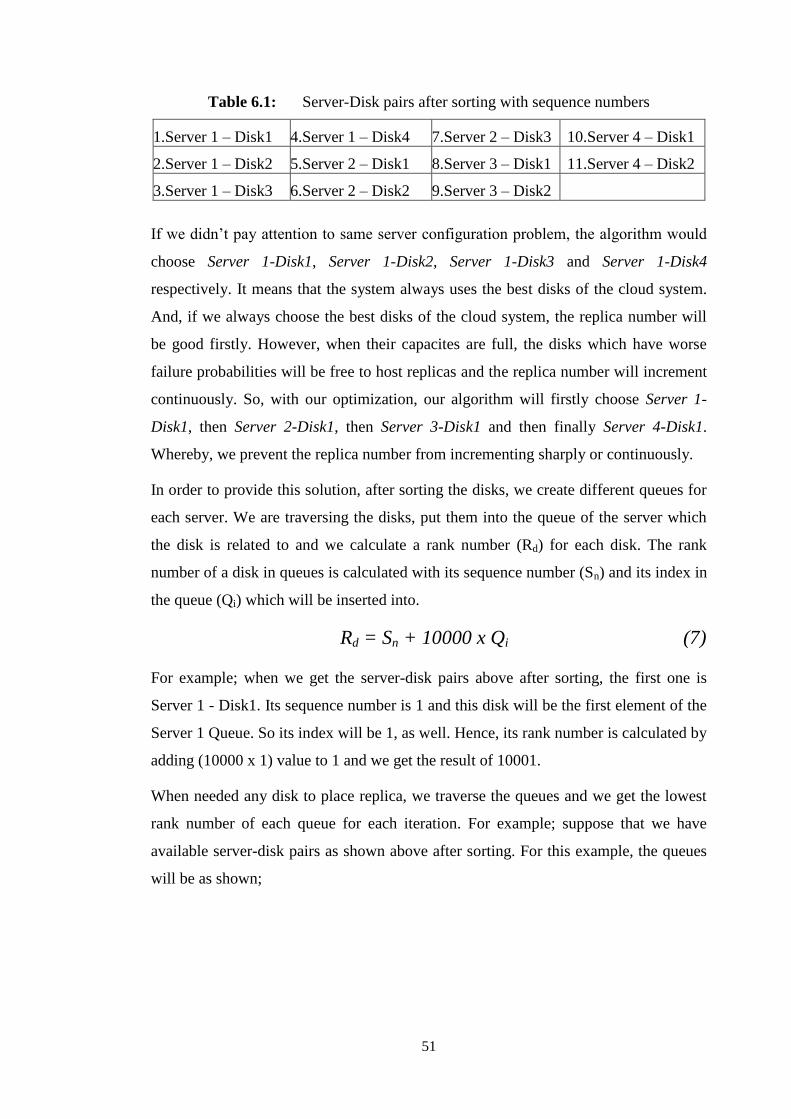
51
Table 6.1: Server-Disk pairs after sorting with sequence numbers
1.Server 1 – Disk1 4.Server 1 – Disk4 7.Server 2 – Disk3 10.Server 4 – Disk1
2.Server 1 – Disk2 5.Server 2 – Disk1 8.Server 3 – Disk1 11.Server 4 – Disk2
3.Server 1 – Disk3 6.Server 2 – Disk2 9.Server 3 – Disk2
If we didn’t pay attention to same server configuration problem, the algorithm would
choose Server 1-Disk1, Server 1-Disk2, Server 1-Disk3 and Server 1-Disk4
respectively. It means that the system always uses the best disks of the cloud system.
And, if we always choose the best disks of the cloud system, the replica number will
be good firstly. However, when their capacites are full, the disks which have worse
failure probabilities will be free to host replicas and the replica number will increment
continuously. So, with our optimization, our algorithm will firstly choose Server 1-
Disk1, then Server 2-Disk1, then Server 3-Disk1 and then finally Server 4-Disk1.
Whereby, we prevent the replica number from incrementing sharply or continuously.
In order to provide this solution, after sorting the disks, we create different queues for
each server. We are traversing the disks, put them into the queue of the server which
the disk is related to and we calculate a rank number (Rd) for each disk. The rank
number of a disk in queues is calculated with its sequence number (Sn) and its index in
the queue (Qi) which will be inserted into.
Rd = Sn + 10000 x Qi (7)
For example; when we get the server-disk pairs above after sorting, the first one is
Server 1 - Disk1. Its sequence number is 1 and this disk will be the first element of the
Server 1 Queue. So its index will be 1, as well. Hence, its rank number is calculated by
adding (10000 x 1) value to 1 and we get the result of 10001.
When needed any disk to place replica, we traverse the queues and we get the lowest
rank number of each queue for each iteration. For example; suppose that we have
available server-disk pairs as shown above after sorting. For this example, the queues
will be as shown;

52
Table 6.2: Each Queue and its disks
S1 Queue → Disk1,Rd:10001 Disk2,Rd:20002 Disk3,Rd:30003 Disk4,Rd:40004
S2 Queue → Disk1,Rd:10005 Disk2,Rd:20006 Disk3,Rd:30007
S3 Queue → Disk1,Rd:10008 Disk2,Rd:20009
S4 Queue → Disk1,Rd:10010 Disk2,Rd:20011
When needed an available disk to place replica, the queues are traversed respectively.
If one disk is required, then the disk with lowest rank is removed from server 1 queue
and replica is placed into it. If one disk is not enough to provide system availability
and two disks are required, then the disk with lowest rank is removed from server 2
queue to place the second replica. As we described above, the disks from the same
server are not preferred. However, sometimes the disks from only one server may be
left to store the object replicas. In such situation, if there are enough disks to put
replicas of the object, those disks are used.
The algorithm will continue in this way until the system availability expected by user
is satistfied. The steps of our algorithm to find the replica count and the disks to place
replica are shown as follows.
Inputs: disk failure probability (fpi) and read latency, server locations, read latency
expected by user, system availability expected by user (α), failure prob. weight,
distance weight, disk load rate weight.
Outputs: Replica count (RC) and disk list to place replicas (DL)
begin
Collect all disks with enough capacity to store object.
Remove disks with read latency which is smaller than read latency expected by user.
Calculate weights of disks.
Sort disks with their weights.
Create and fill queues with respect to disks.
Actual → 0, RC → 0, DL → {}

53
while (actual < α)
RC++
DL → {}
multiplication → 1
for (i=0; i< RC; i++)
Get the best disk Dbest from queues
Add it to DL
Multiplication * = fp of Dbest
end
Actual = 1 - multiplication
end
Return DL
end
Figure 6.7: Algorithm: Our strategy for replica placement

54

55
7. PERFORMANCE EVALUATION
While evaluating the system design performance, we developed three graphical user
interface to create inputs and to run main program in an easily way. These screens are
respectively shown as below.
7.1 Generate Cloud GUI
When you run Generate Cloud GUI, the screen will be opened with default parameters
as shown below. You can edit any parameters you want.
Figure 7.1: Generate Cloud GUI Screen
You can give your cloud name which will be name of the cloud file, location name
which will be the location of the cloud system. You can provide your failure
probability, distance and disk load rate weights which will be used for sorting

56
available disks to put the replica of an object. You can also set Minimum provided
availability which matches an SLA requirement of a user request. It determines that
this cloud can accept user requests or not.
When you click “Add New Server” button, a new row will be created on the table
shown below with default parameters. You can click any column of the row and set
your own parameters. You can add servers as much as you wish which will belong to
this cloud definition.
Figure 7.2: Adding servers and their configuration screen
You can define server names, their x and y coordinates, number of disks that they have
and failure probabilities of each disk in the server by giving your own parameters for
server.
When you click Generate button, model file representing the cloud environment is
generated on the location which is output file path given by user on the screen. For this
given parameters, the cloud model file is generated as shown in Appendix A.
7.2 Sequence Generator GUI
As explained in Storage CloudSim section, user requirements and requests are defined
in usage sequence files. In order to evaluate our system architecture, as it is diffucult to
create each sequence file manually, we developed a GUI to create automatically usage
sequence files as much as you wish to make our test easier.
When you run Usage Sequence Generator GUI, the screen will be opened with default
parameters as shown below. You can edit any parameters you want.

57
Figure 7.3: Sequence Generator GUI Screen
You can set user location as x and y coordinators. You can also set desired read
latency which represents the minimum read latency of a candidate disk to contain
user’s objects. If disk’s read latency is higher than this value given by user, the disk
will be ignored and wont be able to store the requesting user’s object.
You can also give the expected minimum availability. This is an SLA requirement
which matches the availability defined in the cloud model file. The cloud model which
meets this SLA requirement will get the requests of a user sequence file.
Number of Sequences parameter defines the number of usage sequence file with the
same parameters.
For these sample parameters, when you click Generate Sequences button, 300 usage
sequence files will be generated with the same parameters given by the screen.
An example of usage sequence files is shown below.
<usageSequence sequenceID="1"> <SLA> <requirements class="edu.kit.cloudSimStorage.ObjectStorageSLAs. matchingSLA.SLARequirementAND"> <a class="edu.kit.cloudSimStorage.ObjectStorageSLAs. matchingSLA.SLARequirementAND"> <a class="edu.kit.cloudSimStorage.ObjectStorageSLAs. matchingSLA.SLARequirementAND">

58
<a class="edu.kit.cloudSimStorage.ObjectStorageSLAs. matchingSLA.SupportsCapability" description="cdmi_create_container!" capability_key="cdmi_create_container"/> <b class="edu.kit.cloudSimStorage.ObjectStorageSLAs. matchingSLA.SupportsCapability" description="cdmi_delete_container!" capability_key="cdmi_delete_container"/> </a> <b class="edu.kit.cloudSimStorage.ObjectStorageSLAs. matchingSLA.MinimumCharactersisticValue" description="SLA minimum availability>=0.99" key="SLA minimum availability" min="0.99"/> </a> <b class="edu.kit.cloudSimStorage.ObjectStorageSLAs. matchingSLA.MinimumCharactersisticValue" description="SLA available capacity>=2.8443936932E10" key="SLA available capacity" min="2.8443936932E10"/> </requirements> <ratings class="edu.kit.cloudSimStorage.ObjectStorageSLAs. ratingSLA.RateByPrice"> <description>rate 1/price for up and download and storage costs</description> </ratings> </SLA> <CommonRequestParams> <readLatency>10.0</readLatency> <coordinateX>10.0</coordinateX> <coordinateY>12.0</coordinateY> </CommonRequestParams> <request class="java.util.ArrayList"> <userRequest delay="0" blockingCall="true" opCode="1" size="0"> <containerName>files</containerName> <objectID>UNKNOWN</objectID> <metadata> <metadata/> </metadata> </userRequest> <userRequest delay="0" blockingCall="false" opCode="0" size="8821857212"> <objectName>fa7wwt5ir8f9ncqxm</objectName> <containerName>files</containerName> <objectID>UNKNOWN</objectID> <metadata> <metadata> <entry> <string>cdmi_size</string> <string>8821857212</string> </entry> </metadata> </metadata> </userRequest> <userRequest delay="6994" blockingCall="false" opCode="6" size="0"> <objectID>UNKNOWN</objectID> </userRequest> <userRequest delay="0" blockingCall="false" opCode="0" size="3838355570"> <objectName>b7tnya2jqk</objectName> <containerName>files</containerName> <objectID>UNKNOWN</objectID>

59
<metadata> <metadata> <entry> <string>cdmi_size</string> <string>3838355570</string> </entry> </metadata> </metadata> </userRequest> <userRequest delay="8975" blockingCall="false" opCode="6" size="0"> <objectID>UNKNOWN</objectID> </userRequest> <userRequest delay="0" blockingCall="false" opCode="0" size="7222991320"> <objectName>7xdwxdd41us</objectName> <containerName>files</containerName> <objectID>UNKNOWN</objectID> <metadata> <metadata> <entry> <string>cdmi_size</string> <string>7222991320</string> </entry> </metadata> </metadata> </userRequest> <userRequest delay="2334" blockingCall="false" opCode="6" size="0"> <objectID>UNKNOWN</objectID> </userRequest> <userRequest delay="0" blockingCall="false" opCode="0" size="10635145281"> <objectName>46180f20hsh8chqhhx</objectName> <containerName>files</containerName> <objectID>UNKNOWN</objectID> <metadata> <metadata> <entry> <string>cdmi_size</string> <string>10635145281</string> </entry> </metadata> </metadata> </userRequest> <userRequest delay="7784" blockingCall="false" opCode="6" size="0"> <objectID>UNKNOWN</objectID> </userRequest> </request>
</usageSequence>
Figure 7.4: Generated User Sequence file example
As you can see above, there are some requests with different object size and object
names. These are also different from the ones in another usage sequence files.

60
7.3 Main GUI
There is no screen to run Main class in Storage CloudSim framework. Also, it is
diffucult to test the algorithm with different weights to sort disks.
This screen gets the weights to sort candidate disks to place the replica of an object.
You can set failure probability, distance and disk load rate weights from the screen.
These parameters will replace the existing parameters in cloud model file shown under
the tag <weightParamsToChooseBestDisk> since it is diffucult to change the xml file
everytime we need a different test for users.
Figure 7.5: Main Screen
When you click “Run Program”, it will replace the parameters in the cloud model file
and start the program with the cloud having these new weight parameters.
7.4 Experiments
As our proposed cloud storage system is implemented with Storage CloudSim, in
order to test our works, we created sequence files which contain the requirements of
users and their requests by using the GUI as shown in section 7.3. We also defined a
cloud model file to simulate a real cloud environment by using the screen as described
in section 7.1. Our system processes the put or update requests until there is no enough
space in the disks of the cloud environment to place replicas. If there is not enough
space, the other requests are discarded.

61
We made our experiments with only one cloud environment (thus, we created only one
cloud model file) since our aim is mainly to show how replicas are distributed to the
disks of servers and how replica number changes for each request in one cloud, not
multiple clouds. Our test cloud environment includes five servers and three disks with
the same capacity in each server. The servers have the same location coordinators with
related to our aim although we use distance weight to sort disks. Thus, even if the
locations of servers were not the same, our system could choose the servers closer to
user.
The cloud model is modeled to be able to meet the system availability as percentage of
0.9999999. Three hundred of usage sequence files have been generated for the
experiment. All of them includes an SLA requirement with minimum expected
availability as 0.9999999, so all sequences can be processed with our cloud
environment since cloud model can meet this requirement.
The failure probabilities of the disks of servers were defined as 0.0001, 0.001, 0.009,
0.03 and 0.05, namely, the failure probabilities of the disks of Server 1 are defined as
0.0001, the ones for the disks of Server 5 are defined as 0.05. All disks have the same
capacity and the same read/write latency values.
We made two different experiments shown at the table below.
Table 7.1: Experiment Types
Experiment θ β γ Same server optimization
1 1 0 0 No
2 0.5 0.3 0.2 Yes
In the experiments, we give different weights for disk failure probability, distance
between user requesting and servers and current disk load rate to sort disks in our
cloud environment as described in section 1.2. The last column of the table, same
server optimization means our optimization described in section 1.3. Namely, for the
second and consecutive disk selections to place replicas, it prefers the disks from
different servers in each iteration. After running the tests, we showed our results with
some graphics to show the efficiency of our algorithm. One of the graphics is to show

62
the replica number found for each request. The second ones are to show the load rates
of each disk for each request, so that we can see the load balancing among servers in
our cloud environment. The last ones are to display the load rates of the disks as bar
graphic. Disk load rate graphic as bar presentation shows the load rates of all disks for
every 25th
requests.
With the first experiment, we give failure probability weight as 1, so that we can see
what happens if we don’t involve the distance and disk load rate optimizations. Also,
we don’t apply the optimization with related to disk selection from the same server.
Thus, for the user requests, many of the best disks to place the replicas may belong to
the same server.
Figure 7.6: Replica count graphic for experiment 1

63
As shown in replica count graphic for experiment 1, replica count firstly starts with
two replicas. When the bests disks are full, then it becomes three replicas. When the
bests ones of remaining disks are full, then it becomes four replicas. Finally, our
system couldnt find enough disks to put replicas since replica count will sharply
increment and stopped processing user requests on 158th request.
The disk load graphic for experiment 1 as seen below shows that disk load balancing
can not be supplied among candidate disks of servers. Always the same disks store the
replicas until they have not enough space since they have always the higher weights
among all candidate disks to store each object and the other ones dont store.
Figure 7.7: Load rate graphic for experiment 1

64
Figure 7.8: Graphic for disk load rates as bar representation in experiment 1
In figure 7.7 such as 7.8, it is seen that the same disk pairs host the replicas and the
balancing cannot be provided since the same server optimization is not applied. When
the best disks are full, then replicas are placed into the best ones of the remaining
disks. It continues in this way. And there are still disks which dont have any object
replicas although some of the disks are full when the system stops processing on 158th
request. The reason why there are still empty disks which dont have any object replica
is that the system needs much more replicas after 158th request; however there are not
sufficient number of disks to place the replicas. If there were enough of disks to place
the replicas after 158th request, we could see that the replica number would sharply
increment.
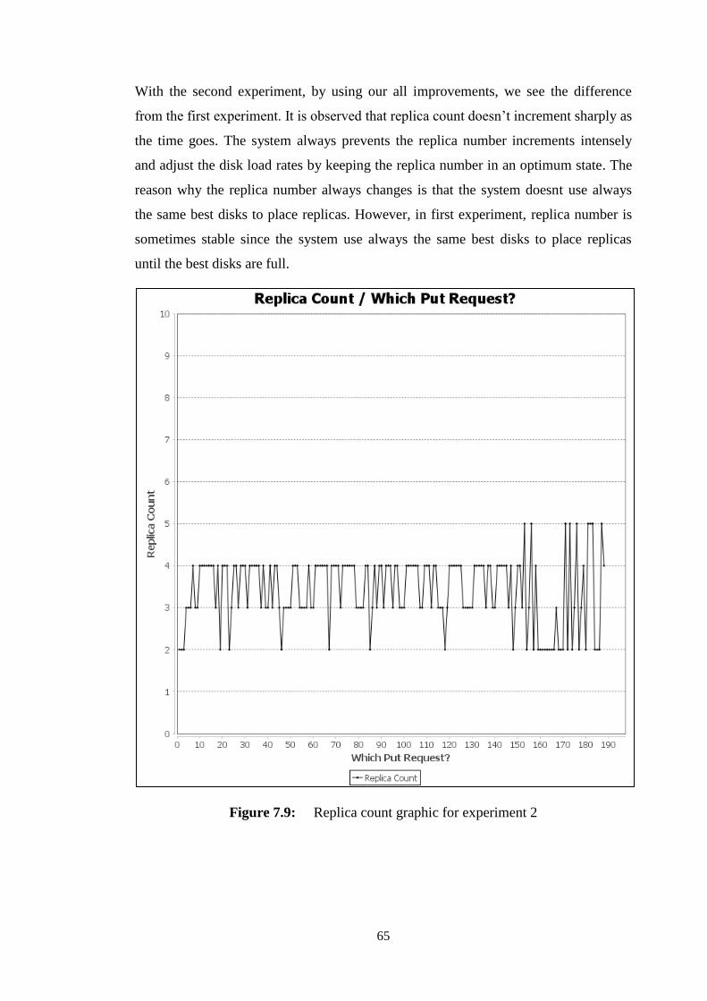
65
With the second experiment, by using our all improvements, we see the difference
from the first experiment. It is observed that replica count doesn’t increment sharply as
the time goes. The system always prevents the replica number increments intensely
and adjust the disk load rates by keeping the replica number in an optimum state. The
reason why the replica number always changes is that the system doesnt use always
the same best disks to place replicas. However, in first experiment, replica number is
sometimes stable since the system use always the same best disks to place replicas
until the best disks are full.
Figure 7.9: Replica count graphic for experiment 2

66
Furthermore, the system could process more user requests in experiment 1 than in
experiment 2 since the replica number didnt get high value and the disks could place
much more replicas in experiment 1.
Figure 7.10: Graphic for disk load rates in experiment 2
Also, the disk usage is balanced among server disks on a large scale as shown both in
figure 7.10 and 7.11. All disks get the replicas in a balanced way from the beginning
to the end of the user requests during the experiment. It is obviously seen that we
could prevent the usage of always the same bests disks when we needed to place a
replica.
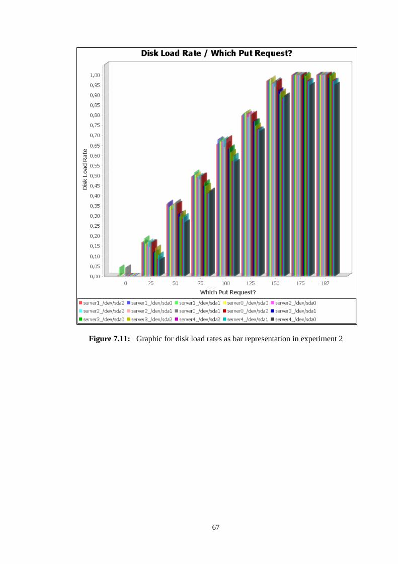
67
Figure 7.11: Graphic for disk load rates as bar representation in experiment 2

68

69
8. CONCLUSION
In this thesis, we proposed a new design for dynamic replication strategy for cloud
storage systems. Different replica placement and replica count strategies are proposed
by researchers. As our study is interested in not only system availability, but also
bandwidth usage and load balancing among servers, we performed different
optimizations which are not included in other studies. Most of the techniques proposed
are based on simulation, not on real time implementation. Implementing these
replication techniques, testing and evaluating the actual efficiency is an interesting
open problem. In future, we intent to move our works into a real cloud environment
and see how it works in real life.

70

71
REFERENCES
[1] Chang, G.R., Gao, S., Jin, L.Z., Sun, D.W., and Wang, X.W. (2012).
“Modelling a Dynamic Replication Strategy to Increase System
Availability in Cloud Environments”, Journal of Computer Science
and Technology, 27(2), pp. 256-272
[2] Jrad, F., Sturm, T., and Streit, A. (2014). “Storage CloudSim: A Simulation
Environment for Cloud Object Storage Infrastructures”, In
Proceedings of the 4th International Conference on Cloud Computing
and Services Science, pp. 186-192
[3] Beloglazov, A., Buyya, R., Calheiros, R.N., De Rose, C.A.F., and Ranjan, R.
(2011). “CloudSim: a toolkit for modeling and simulation of cloud
computing environments and evaluation of resource provisioning
algorithms”, Software Practice and Experience, 41(1), pp.23-50
[4] Ghemawat, S., Gobio, H. and Leung, S.T. (2003). “The Google File system,
ACM SIGOPS Operating Systems Review”, 37(5), pp. 29-43
[5] Chansler, R., Hairong, K., Radia, S., and Shvachko, K. (2010). “The Hadoop
distributed file system, In: Proc. the 26th Symposium on Mass
Storage Systems and Technologies”, pp. 1-10, Incline Village, NV,
USA,
[6] Myint, J., and Naing, T.T. (2011). “Management of Data Replication for PC
Cluster Based Cloud Storage System”, International Journal on Cloud
Computing: Services and Architecture(IJCCSA), Vol.1. No.3
[7] Grace, R.K., and Manimegalai, R. (2013). R., “Dynamic Replica Placement
and Selection Strategies in Data Grids, A Comprehensive Survey”,
Journal of Parallel and Distributed Computing,
[8] Hussein, M.K., and Mousa, M.H. (2012). “A Light-weight Data Replication for
Cloud Data Centers Environment”, International Journal of
Engineering and Innovative Technology(IJEIT), Volume 1, Issue 6
[9] BCS (2012). “Cloud Computing: Moving IT Out of the Office”, The Chartered
Institute for IT(Editor)
[10] Sturm, T. (2013). “Implementation of a Simulation Environment for Cloud
Object Storage Infrastructures”, Department of Informatics, Steinbuch
Centre for Computing, Karlsruhe Institute of Technology
[11] Cloud Data Management Interface (CDMI) Version 1.0.2.
[12] Azagury, A., Dreizin, V., Factor, M., Henis, E., Naor, D., Rinetzky, N.,
Rodeh, O., Satran, J., Tavory, A., and Yerushalmi, L. (2003).
“Towards an object store”, pp. 165-176.
[13] Factor, M., Meth, K., Naor, D., Rodeh, O., and Satran, J. (2005). “Object
storage: the future building block for storage systems”, pp. 119-123,.

72
[14] Amazon Inc. Amazon s3 (2013),Cloud computing storage for files, images,
videos,.[Online; accessed 17-July-2013].
[15] OpenStack Foundation (2013), Openstack open source cloud computing
software, [Online; accessed 19-Aug-2013].

73
APPENDICES
APPENDIX A: Generated Cloud File Example
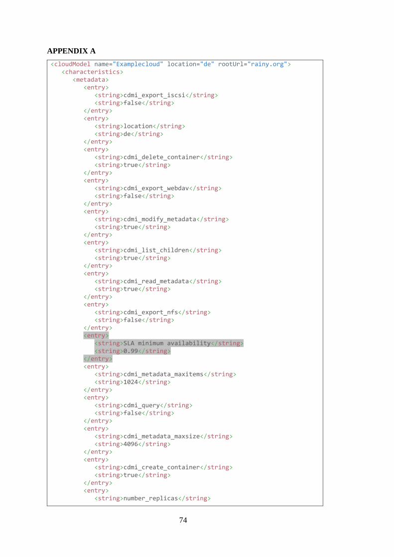
74
APPENDIX A
<cloudModel name="Examplecloud" location="de" rootUrl="rainy.org"> <characteristics> <metadata> <entry> <string>cdmi_export_iscsi</string> <string>false</string> </entry> <entry> <string>location</string> <string>de</string> </entry> <entry> <string>cdmi_delete_container</string> <string>true</string> </entry> <entry> <string>cdmi_export_webdav</string> <string>false</string> </entry> <entry> <string>cdmi_modify_metadata</string> <string>true</string> </entry> <entry> <string>cdmi_list_children</string> <string>true</string> </entry> <entry> <string>cdmi_read_metadata</string> <string>true</string> </entry> <entry> <string>cdmi_export_nfs</string> <string>false</string> </entry> <entry> <string>SLA minimum availability</string> <string>0.99</string> </entry> <entry> <string>cdmi_metadata_maxitems</string> <string>1024</string> </entry> <entry> <string>cdmi_query</string> <string>false</string> </entry> <entry> <string>cdmi_metadata_maxsize</string> <string>4096</string> </entry> <entry> <string>cdmi_create_container</string> <string>true</string> </entry> <entry> <string>number_replicas</string>

75
<string>3</string> </entry> <entry> <string>cdmi_notification</string> <string>false</string> </entry> <entry> <string>cdmi_queues</string> <string>false</string> </entry> <entry> <string>SLA download costs</string> <string>0.1</string> </entry> <entry> <string>keep_n_versions</string> <string>1</string> </entry> <entry> <string>SLA storage costs</string> <string>0.1</string> </entry> <entry> <string>cdmi_domains</string> <string>false</string> </entry> <entry> <string>SLA upload costs</string> <string>0.1</string> </entry> </metadata> </characteristics> <pricingPolicy class="edu.kit.cloudSimStorage.pricing.SimplePricing"> <centsPerUploadedGB>0.1</centsPerUploadedGB> <centsPerDownloadedGB>0.1</centsPerDownloadedGB> <centsPerStoredGBperPeriod>0.1</centsPerStoredGBperPeriod> </pricingPolicy> <weightParamsToChooseBestDisk> <failureProbabilityWeight>0.5</failureProbabilityWeight> <distanceWeight>0.3</distanceWeight> <diskLoadRateWeight>0.2</diskLoadRateWeight> </weightParamsToChooseBestDisk> <servers class="java.util.ArrayList"> <objectStorageServerModel> <name>server0</name> <locationName>Turkey</locationName> <coordinateX>10.0</coordinateX> <coordinateY>12.0</coordinateY> <ioLimitations class="edu.kit.cloudSimStorage.storageModel. resourceUtilization.FirstFitAllocation" maxRate="1.34217728E11"/> <disks class="java.util.ArrayList"> <objectStorageDiskModel> <drive class="edu.kit.cloudSimStorage.cloudScenarioModels. GenericDrive" name="/dev/sda0"> <capacity>1099511627776</capacity> <reserverdSpace>0</reserverdSpace> <usedSpace>0</usedSpace> <readRate>2.2020096E8</readRate>

76
<writeRate>2.2020096E8</writeRate> <readLatency>8.5</readLatency> <writeLatency>9.5</writeLatency> <failureProbability>0.2</failureProbability> <ioLimits class="edu.kit.cloudSimStorage.storageModel. resourceUtilization.FirstFitAllocation" maxRate="2.2020096E11"/> </drive> <name>/dev/sda0</name> </objectStorageDiskModel> <objectStorageDiskModel> <drive class="edu.kit.cloudSimStorage.cloudScenarioModels. GenericDrive" name="/dev/sda1"> <capacity>1099511627776</capacity> <reserverdSpace>0</reserverdSpace> <usedSpace>0</usedSpace> <readRate>2.2020096E8</readRate> <writeRate>2.2020096E8</writeRate> <readLatency>8.5</readLatency> <writeLatency>9.5</writeLatency> <failureProbability>0.2</failureProbability> <ioLimits class="edu.kit.cloudSimStorage.storageModel. resourceUtilization.FirstFitAllocation" maxRate="2.2020096E11"/> </drive> <name>/dev/sda1</name> </objectStorageDiskModel> <objectStorageDiskModel> <drive class="edu.kit.cloudSimStorage.cloudScenarioModels. GenericDrive" name="/dev/sda2"> <capacity>1099511627776</capacity> <reserverdSpace>0</reserverdSpace> <usedSpace>0</usedSpace> <readRate>2.2020096E8</readRate> <writeRate>2.2020096E8</writeRate> <readLatency>8.5</readLatency> <writeLatency>9.5</writeLatency> <failureProbability>0.2</failureProbability> <ioLimits class="edu.kit.cloudSimStorage.storageModel. resourceUtilization.FirstFitAllocation" maxRate="2.2020096E11"/> </drive> <name>/dev/sda2</name> </objectStorageDiskModel> </disks> </objectStorageServerModel> <objectStorageServerModel> <name>server1</name> <locationName>Turkey</locationName> <coordinateX>10.0</coordinateX> <coordinateY>12.0</coordinateY> <ioLimitations class="edu.kit.cloudSimStorage.storageModel. resourceUtilization.FirstFitAllocation" maxRate="1.34217728E11"/> <disks class="java.util.ArrayList"> <objectStorageDiskModel> <drive class="edu.kit.cloudSimStorage.cloudScenarioModels. GenericDrive" name="/dev/sda0"> <capacity>1099511627776</capacity>

77
<reserverdSpace>0</reserverdSpace> <usedSpace>0</usedSpace> <readRate>2.2020096E8</readRate> <writeRate>2.2020096E8</writeRate> <readLatency>8.5</readLatency> <writeLatency>9.5</writeLatency> <failureProbability>0.2</failureProbability> <ioLimits class="edu.kit.cloudSimStorage.storageModel. resourceUtilization.FirstFitAllocation" maxRate="2.2020096E11"/> </drive> <name>/dev/sda0</name> </objectStorageDiskModel> <objectStorageDiskModel> <drive class="edu.kit.cloudSimStorage.cloudScenarioModels. GenericDrive" name="/dev/sda1"> <capacity>1099511627776</capacity> <reserverdSpace>0</reserverdSpace> <usedSpace>0</usedSpace> <readRate>2.2020096E8</readRate> <writeRate>2.2020096E8</writeRate> <readLatency>8.5</readLatency> <writeLatency>9.5</writeLatency> <failureProbability>0.2</failureProbability> <ioLimits class="edu.kit.cloudSimStorage.storageModel. resourceUtilization.FirstFitAllocation" maxRate="2.2020096E11"/> </drive> <name>/dev/sda1</name> </objectStorageDiskModel> <objectStorageDiskModel> <drive class="edu.kit.cloudSimStorage.cloudScenarioModels. GenericDrive" name="/dev/sda2"> <capacity>1099511627776</capacity> <reserverdSpace>0</reserverdSpace> <usedSpace>0</usedSpace> <readRate>2.2020096E8</readRate> <writeRate>2.2020096E8</writeRate> <readLatency>8.5</readLatency> <writeLatency>9.5</writeLatency> <failureProbability>0.2</failureProbability> <ioLimits class="edu.kit.cloudSimStorage.storageModel. resourceUtilization.FirstFitAllocation" maxRate="2.2020096E11"/> </drive> <name>/dev/sda2</name> </objectStorageDiskModel> </disks> </objectStorageServerModel> <objectStorageServerModel> <name>server2</name> <locationName>Turkey</locationName> <coordinateX>10.0</coordinateX> <coordinateY>12.0</coordinateY> <ioLimitations class="edu.kit.cloudSimStorage.storageModel. resourceUtilization.FirstFitAllocation" maxRate="1.34217728E11"/> <disks class="java.util.ArrayList"> <objectStorageDiskModel>

78
<drive class="edu.kit.cloudSimStorage.cloudScenarioModels. GenericDrive" name="/dev/sda0"> <capacity>1099511627776</capacity> <reserverdSpace>0</reserverdSpace> <usedSpace>0</usedSpace> <readRate>2.2020096E8</readRate> <writeRate>2.2020096E8</writeRate> <readLatency>8.5</readLatency> <writeLatency>9.5</writeLatency> <failureProbability>0.2</failureProbability> <ioLimits class="edu.kit.cloudSimStorage.storageModel. resourceUtilization.FirstFitAllocation" maxRate="2.2020096E11"/> </drive> <name>/dev/sda0</name> </objectStorageDiskModel> <objectStorageDiskModel> <drive class="edu.kit.cloudSimStorage.cloudScenarioModels. GenericDrive" name="/dev/sda1"> <capacity>1099511627776</capacity> <reserverdSpace>0</reserverdSpace> <usedSpace>0</usedSpace> <readRate>2.2020096E8</readRate> <writeRate>2.2020096E8</writeRate> <readLatency>8.5</readLatency> <writeLatency>9.5</writeLatency> <failureProbability>0.2</failureProbability> <ioLimits class="edu.kit.cloudSimStorage.storageModel. resourceUtilization.FirstFitAllocation" maxRate="2.2020096E11"/> </drive> <name>/dev/sda1</name> </objectStorageDiskModel> <objectStorageDiskModel> <drive class="edu.kit.cloudSimStorage.cloudScenarioModels. GenericDrive" name="/dev/sda2"> <capacity>1099511627776</capacity> <reserverdSpace>0</reserverdSpace> <usedSpace>0</usedSpace> <readRate>2.2020096E8</readRate> <writeRate>2.2020096E8</writeRate> <readLatency>8.5</readLatency> <writeLatency>9.5</writeLatency> <failureProbability>0.2</failureProbability> <ioLimits class="edu.kit.cloudSimStorage.storageModel. resourceUtilization.FirstFitAllocation" maxRate="2.2020096E11"/> </drive> <name>/dev/sda2</name> </objectStorageDiskModel> </disks> </objectStorageServerModel> </servers> <cloudIOLimits class="edu.kit.cloudSimStorage.storageModel. resourceUtilization.UnlimitedResource"/>
</cloudModel>
Figure A.1: Generated Cloud file example

79
CURRICULUM VITAE
Name Surname: Murat ÖZTÜRK
Place and Date of Birth: Denizli, 17.11.1987
E-Mail: [email protected]
EDUCATION:
B.Sc.: Computer Engineering, Ege University
PROFESSIONAL EXPERIENCE AND REWARDS:
TAİ (06.2009 – 07.2009) Intern Software Engineer
IBTEch (07.2009 – 08.2009) Intern Software Engineer
Turkcell PAF Team (08.2009 – 10.2009) Intern Software Engineer
NETSİS (04.2010 – 06.2010) PartTime Software Engineer
Vodafone (2010- 2013) Software Development Engineer
IBTech (2013 - …) Designer
PUBLICATIONS, PRESENTATIONS AND PATENTS ON THE THESIS:
Öztürk M., and Erdoğan N., 2015: A Data Replication Strategy To Improve System
Availability For Cloud Storage Systems. International Conference on
Communication and Computing(ICC-2015) – July 9-11, 2015 Bangalore, India.

80
OTHER PUBLICATIONS, PRESENTATIONS AND PATENTS :
Öztürk M., Yenigün Y., Tunalı A.Ç., and Yaycıoğlu O.T., 2015: RESTful
Konfigurasyon Yönetimi Web Arayüzü. 6th
National Software Engineering
Symposium of Turkey – July 20, 2012 Ankara, Turkey.