Embed Size (px)
Citation preview

SUBCOURSE EDITIONSS0002 A
U S ARMY SIGNAL CENTER AND FORT GORDON
INTRODUCTION TO TACTICAL RADIOCOMMUNICATIONS
DEVELOPMENT DATE: MARCH 1993

INTRODUCTION TO TACTICAL RADIO COMMUNICATIONS
Subcourse Number SS0002
EDITION A
United States Army Signal Center and Fort GordonFort Gordon, Georgia 30905-5000
6 Credit Hours
Edition Date: March 1993
SUBCOURSE OVERVIEW
This subcourse presents the basic theory of radio operation, thedifferent types of tactical radios currently in use, and basictactical radio communications procedures.
There are no prerequisites for this subcourse.
This subcourse reflects the doctrine which was current at the time itwas prepared. In your own work situation, always refer to the latestofficial publications.
Unless otherwise stated, the masculine gender of singular pronouns isused to refer to both men and women.
TERMINAL LEARNING OBJECTIVE
ACTION: Identify and describe the basic principles of radiocommunications and apply those principles to tacticalradio communications. You will also become familiar withthe tactical radio equipment and communicationsprocedures currently in use in the field. You will alsolearn about the organization, equipment capabilities, andprocedures for the Single-Channel Ground and AirborneRadio System and improved high frequency radio systems.
CONDITION: You will be given information from this subcourse.
STANDARD: To demonstrate competency of this task, you must achievea minimum score of 70% on the subcourse examination.
i SS0002

TABLE OF CONTENTS
Section Page
Subcourse Overview ................................................. i
Administrative Instructions ...................................... iii
Grading and Certification Instructions ........................... iii
Lesson 1: Introduction to Tactical Radio Communications Theory . 1-1
Practice Exercise ................................... 1-29
Answer Key and Feedback ............................. 1-30
Lesson 2: Tactical Continuous Wave and Voice Radio Equipment ... 2-1
Practice Exercise .................................... 2-9
Answer Key and Feedback ............................. 2-12
Lesson 3: Tactical Radio Voice Operation ....................... 3-1
Practice Exercise ................................... 3-21
Answer Key and Feedback ............................. 3-22
Lesson 4: Tactical Radio Teletypewriter Equipment .............. 4-1
Practice Exercise .................................... 4-9
Answer Key and Feedback ............................. 4-10
Lesson 5: Single-Channel Ground and Airborne Radio System (SINCGARS)and Improved High Frequency Radio (IHFR) Operation ... 5-1
Practice Exercise ................................... 5-13
Answer Key and Feedback ............................. 5-14
Examination ...................................................... E-1
Appendix: List of Acronyms ....................................... A-1
Student Inquiry Sheets
ii SS0002

THIS PAGE INTENTIONALLY LEFT BLANK.
iii SS0002

THIS PAGE IS INTENTIONALLY LEFT BLANK.
iv SS0002

LESSON 1
INTRODUCTION TO TACTICAL RADIO COMMUNICATIONS THEORY
CRITICAL TASKS: 01-5878.04-0005,01-5778.07-0003, 01-5778.07-0007
OVERVIEW
LESSON DESCRIPTION:
In this lesson you will learn the basic theory of tactical radiocommunications including types of modulation (frequency modulation(FM) and amplitude modulation (AM)), transmission characteristics forvarious frequency ranges, antenna characteristics, and how to selectan antenna for a specific communications task.
TERMINAL LEARNING OBJECTIVE:
ACTIONS: a. Describe the operation of a basic frequencymodulation, amplitude modulation/double sideband, andamplitude modulation/single sideband transmitter andreceiver.
b. Define transmission characteristics of high frequency(HF), very high frequency (VHF), and ultra highfrequency (UHF) radio waves.
c. Select tactical antennas for specific tactical radiotransmission requirements.
d. Determine the antenna polarization to obtain optimumcommunications when using tactical radio sets.
e. Recognize and describe the four conditions that mustbe considered for compatibility between differentradio sets.
CONDITION: You will be given information from this lesson.
STANDARD: To demonstrate competency of the terminal learningobjective, you must achieve a minimum score of 70% on thesubcourse examination.
REFERENCES: The material contained in this lesson was derived fromthe following publication: FM 24-18.
1-1 SS0002

INTRODUCTION
The advent of modern transportation has changed the face of thebattlefield immensely. Gone are the days when the messenger couldrun through the trenches to the headquarters tent with on urgentmessage for the Officer in Charge. Today that headquarters may be asmuch as 500 miles away, and that is a little too far even for thehardiest marathon runner. We must now rely on other moresophisticated means to get messages from the front lines to the"Headquarters Tent." In addition, the introduction of aircraft tothe modern battlefield has added a third dimension to the way we mustthink about coordinating our forces.
The medium that brings all the elements of the modern battlefieldtogether and ensures a coordinated effort is radio. The radio hasbecome the central nervous system of the battlefield, keeping eachelement informed of the progress of the whole. As signal officers,it is your job to ensure that these nerves function properly andefficiently. You must be able to make the very best use of each andevery piece of equipment assigned to you and to units under yourcognizance. In order to do this you must first have a thoroughunderstanding of those capabilities, and the best place to start iswith the basics of radio communication theory.
1. Radio Waves.
Radio waves make up one portion of the electromagnetic spectrum. Weidentify a particular radio wave by its frequency. The frequency ofa radio wave is the number of oscillations the wave makes in onesecond. The unit of measurement for radio wave frequency is thehertz (Hz) or cycles per second. One hertz equals one cycle persecond. Another way to measure radio waves is by their wavelength.The wavelength of a wave is simply the distance that the wave travelsas it goes through exactly one cycle. Figure 1-1 illustrates theconcept of wavelength, and figure 1-2 shows a comparison of two wavesof different frequencies. The relationship between a wave'sfrequency and its wavelength is:
In each of these expressions, the number 300,000,000 represents thespeed of light in meters per second.
1-2 SS0002

Figure 1-1. Wavelength of a radio wave
Figure 1-2. Comparison of two waves of different frequency
2. Propagation Methods of Radio Waves.
In order to use radio waves as a communications medium, the wavesmust travel from the sending station to the receiving station. Thus,it is important that you understand something of the propagationmethods of radio waves. Electromagnetic waves travel in a straightline unless they are reflected or refracted by some outside force.In the case of radio waves, the basic paths of transmission are theground wave and the sky-wave. Figure 1-3 illustrates thesetransmission paths.
a. Three Wave Types. All ground waves fall into one of threewave types. The first type is the direct wave. Direct waves travelalong a line of sight (LOS) path. There must be a clear path betweentwo stations in order to communicate using this transmission path.Communications with aircraft, satellites, and stations within sightof each other generally take place along a direct path. The secondtype of ground wave is similar to the direct wave and is called aground reflected wave. Ground reflected waves also travel instraight lines. The difference between this type and the direct waveis that the ground reflected wave is reflected off the ground at somepoint between the sending and receiving stations. Ground reflectedwaves can sometimes interfere with a direct wave signal if both wavesarrive at the receiving station 180 degrees out of phase.
1-3 SS0002

Some of the lower frequency ranges are affected by theelectromagnetic properties of the earth's surface and will actuallybend around the curvature of the earth. These are surface waves.You can communicate with stations not in your LOS using systems thattake advantage of these lower frequencies.
Figure 1-3. Radio wave transmission paths
b. Sky-Waves. The other type of transmission path is the sky-wave. Sky-waves are waves that have been transmitted upward andreflected back to the earth by the ionosphere. The ionosphere is aseries of four layers (in daylight hours) of ion concentration in theearth's atmosphere called the D, E, Fl, and F2 regions. Figure 1-4illustrates the ionosphere regions and their approximate heightsabove the earth's surface. The D region of the ionosphere servesonly to attenuate the strength of radio waves and does not provideany useful reflection of the waves. This region fades out at night.The E region also fades at night but provides some reflection ofradio waves during the day. Sky-waves which bounce off the E regioncan provide communications up to about 2,400 kilometers (1,500miles). The F regions of the ionosphere do not fade out at night butthey do combine to form a single region. You can communicate using Fregion sky-waves over distances of over 2,400 kilometers. Thisregion is especially useful at night when the two intervening regions(D and E) have faded. The ionosphere is not constant and, therefore,sky-wave communications are not completely predictable. Theionosphere constantly undergoes variations which are classified asregular or irregular.
1-4 SS0002

Figure 1-4. Distribution of the ionosphere
(1) Regular variations. Regular variations in the ionosphereoccur as a result of the earth being a satellite of the sun androtating about its own axis. These variations are so called becausethe period of variation is fairly well known from previousobservation. You must account for these variations when you planyour communications system. There are four basic types of regularvariations, which are:
(a) Daily variations. These are caused by the rotation ofthe earth.
(b) Seasonal variations. These are caused by the seasonaltilt of the earth on its axis.
(c) 27-day variations. These are caused by the rotation ofthe sun on its axis.
1-5 SS0002
(d) 11-year variations. These are caused by the sunspotactivity cycle of the sun.
(2) Irregular variations. Irregular variations in theionosphere occur as a result of random events. Because thesevariations occur randomly, you cannot anticipate or plan for them.There are three basic types of irregular variations, which are:
(a) Sporadic E. This is caused by the E region becominghighly ionized and blocking out the reflections from the F regions.This can completely blank out sky-wave signals or it can result insignals traveling much further than you would normally expect.
(b) Sudden ionospheric disturbance (SID). This is caused bybright solar eruptions. The eruption causes abnormal ionization ofthe D region, absorbing all frequencies above approximately 1megahertz (MHz). This results in receivers seeming to go dead, andit can last for several hours. Since it is associated with the Dregion of the ionosphere, this phenomenon is limited to daylighthours and does not occur after dark.
(c) Ionospheric storms. These are caused by meteorologicaldisturbances in the ionosphere. These storms can involve the entireionosphere and can last from several hours to several days. Thisphenomenon can cause low intensity in sky-wave signals and can causea type of random "flutter fading" in sky-wave signals.
The range of sky-wave radio transmissions depends largely on thedensity of the ionospheric regions and the frequency of the radiosignal. Because the frequency of a radio wave and its energy levelare proportional, higher levels of ionization must exist in theionosphere in order to reflect the waves back to earth. As a result,there is at any given time a frequency above which radio waves willnot be reflected back to earth. This frequency is the criticalfrequency. The critical frequency is not a fixed value because thelevel of ionization in the ionosphere is constantly changing.Another limiting factor associated with the ionosphere is thecritical angle. The critical angle is that angle of incidence (angleat which the radio wave meets the ionosphere) above which the radiowave will not be reflected, but will pass through the ionosphere andbe lost in space.
Two other important terms you should understand when you are dealingwith sky-wave transmissions are skip distance and skip zone. Theskip distance is the distance that a sky-wave travels from itstransmission point to the point where it returns to the earth'ssurface. The skip zone is the area in which no usable
1-6 SS0002

radio signal can be received because it is shorter than the skipdistance but longer than the ground wave range. Figure 1-5illustrates these concepts.
Figure 1-5. Skip zone and skip distance
You can use a piece of equipment called the AN/TRQ-35(V) IonosphericSounder to determine which frequencies are best for sky-wavetransmission at any time of day or night.
3. Useful Frequencies.
The number of useful frequencies in radio communications is verylarge, spanning a range of about thirty kilohertz (30 kHz) to about300 Gigahertz (300 GHz), or 30,000 to 300,000,000,000 Hz. Since thetransmission characteristics of radio waves change as the frequencychanges, it is useful to break this wide range of frequencies intosmaller groups called bands. We divide the radio frequency (RF)spectrum into bands of frequencies which have similar transmissioncharacteristics. Table 1-1 shows these frequency bands and theirrespective frequency ranges.
1-7 SS0002

Most tactical radio sets operate within the medium frequency (MF) toUHF bands.
Table 1-1. Frequency bands
Each of these frequency bands has different transmissioncharacteristics. The frequency range of the band determines how thewaves propagate and how far they travel. Lower frequency bands (VLFand LF), for example, will travel as surface waves and as sky-waves.Frequencies in the UHF and higher ranges, on the other hand,propagate only as direct waves. The other side of the coin is that,because the wave energy is proportional to the wave frequency, lowerfrequency transmitters must use higher transmission power to get ausable signal strength. Table 1-2 shows the relative ranges andtransmission powers required for some of the frequency bands. Theseranges are approximate and do not take into account such variables asionospheric variations, antenna siting problems, and usable antennaorientation or polarization.
Table 1-2. Frequency band characteristics
1-8 SS0002

4. Forms of Radio Communications.
Radio communications can take one of several forms. Messages can bein the form of speech, data, radio teletypewriter (RATT), ortelegraphic code. Let's first consider how a radio set transmitsspeech. The frequency range of normal speech is about 50 Hz to 500Hz. Although these frequencies could be directly converted intoelectromagnetic energy and transmitted, the antenna required would beclose to 5,000 miles long! Thus, you can see that it is notpractical to conduct radio transmissions using this method. Instead,the signal used to transmit speech over radio waves is a combinationof a higher frequency carrier wave and the lower frequency modulatorwave. The sound of speech is converted to electromagnetic energy andthis signal is used to modulate the carrier signal. Using thismethod you can transmit low frequency speech signals using thetransmission characteristics of the higher frequency radio waves.There are two basic types of modulation in radio communications.
a. Frequency Modulation. The first type of modulation isfrequency modulation. In FM transmissions, the modulating signal isused to vary the frequency of the carrier wave. The rate at whichthe carrier frequency varies is equal to the frequency of the audiosignal, and the amount of deviation from the carrier frequency isequal to the amplitude of the audio signal. Thus, an FM transmissionconsists of a constant-amplitude wave with frequency varying about acentral rest frequency. Between the transmitter and receiver the FMtransmission may pick up amplitude variations due to outsideelectromagnetic interference. To compensate, most FM receivers use alimiter to exclude these amplitude variations from the receivedsignal. Because of the variances of the carrier frequency, FMtransmissions usually have fairly large bandwidths. For this reason,FM is generally used in VHF and higher frequency bands wherebandwidth is not as significant as in the lower bands.
b. Amplitude Modulation. The second type of modulation isamplitude modulation. AM is the variation of RF power output of atransmitter at an audio rate. Simply put, AM is the process ofvarying the amplitude (and thus the output energy) of the carrierwave by superimposing the signal wave on it. In an AM transmission,the rate at which the carrier amplitude varies is equal to thefrequency of the audio signal, and the amount of variation in thecarrier amplitude is equal to the amplitude of the audio signal. Inaddition to the amplitude variations of the carrier, thesuperposition of the audio signal produces new RF signals withfrequencies near that of the carrier frequency. For example, assumea 600 kHz carrier is modulated by a .1 kHz audio signal. The two newRF frequencies developed will be 600 kHz +/- .1 kHz, or 599.9 kHz and600.1 kHz. These two new frequencies are called sidebands. Thelower frequency is the lower
1-9 SS0002

sideband and the higher frequency is the upper sideband. Thus for arange of audio frequencies, the frequency range of the sidebandswould be the carrier frequency plus or minus the highest and lowestaudio frequencies. The total space occupied by both sidebands andthe carrier frequency of an AM signal is called a channel, and therange of frequencies is the channel bandwidth. Figures 1-6 and 1-7illustrate the concepts of AM, FM, and sidebands.
Figure 1-6. AM and FM wave shapes
1-10 SS0002

Figure 1-7. AM carrier with sidebands
You may have guessed from the previous information that the sidebandsof an AM transmission contain duplicate information. In fact, theentire audio signal is contained in each sideband. Because of this,we can eliminate the carrier frequency and one sideband frequencyfrom the transmitted signal and still transmit all the informationneeded for communications. This type of transmission is amplitudemodulation/single sideband (AM/SSB) and is further classified asupper sideband (AM/USB) and lower sideband (AM/LSB). Standard AMtransmission is also called AM double sideband (AM/DSB) transmission.One of the main advantages of an AM/SSB system is that by eliminatingone sideband and the carrier frequency you make room in the frequencyspectrum for extra communications channels. Other advantages of aSSB system are:
(1) AM/SSB provides greater reliability than AM/DSB.
(2) AM/SSB systems are smaller and lighter than AM/DSBsystems.
(3) AM/SSB systems provide increased output withoutincreasing antenna voltage.
(4) AM/SSB systems make it possible to operate a largernumber of radio sets without heterodyne interference (whistles andsqueals) from interfering RF carriers.
(5) AM/SSB systems can operate over longer ranges withoutloss of intelligence of the signal due to selective fading.
Because of their narrower bandwidth, AM/SSB systems are used in allfrequency ranges, but are especially useful in the HF and lowerfrequency bands.
1-11 SS0002

5. Basic Transmitter.
Now that you have learned the basic theory of radio signals, the nextthing you need to learn about is how a radio set actually converts aninput signal such as your voice into a radio signal that can travelto a distant station, and how the receiver at that station canconvert that signal back into a recognizable voice pattern. We willstart with a basic transmitter. Figure 1-8 illustrates the basiccomponents of a simple continuous wave (CW) transmitter. Thetransmitter consists of a power supply, a keying device, anoscillator, and an antenna. Let's briefly look at each of thesecomponents.
Figure 1-8. Block diagram of a simple radio transmitter
a. Power Supply. The power supply is common to all radio sets.It simply provides electrical power to all the other components inthe radio set. The power supply may consist of transformers andconvertors and may have multiple output voltages.
b. Oscillator. The oscillator is the device that actuallyproduces the RF signal to be sent. In the early days of radio, theseoscillators consisted of crystals that vibrated at a certainfrequency when stimulated by an electric current. Some older radiosets still use crystal chips in the oscillator, but most modernradios use some type of electronic appurtenance to perform thisfunction. Most tactical radio sets have oscillators that can betuned to a certain frequency or channel for transmission on thatchannel. An oscillator may also contain
1-12 SS0002

filters to limit the bandwidth of the transmission to avoidinterference with other radio sets.
c. Antenna. The antenna is nothing more than the device thatconverts RF electrical energy into radio waves that travel to thereceiving station. You will learn more about antennas later in thislesson.
d. Keying Device. The keying device is the device you use togenerate a message to be transmitted. In the CW transmitter, the keyserves to interrupt the power to the oscillator and antenna. Thus,when the key is depressed, the power is sent to the oscillator andantenna and a signal is transmitted. When the key is released, poweris interrupted and the signal stops. Using this method you can sendMorse code messages by radio.
In order to transmit messages containing something besides Morsecode, you need a transmitter with a few more components. Figure 1-9illustrates a basic radiotelephone transmitter. You can see that amicrophone and modulator have replaced the keying device, and that abuffer and an RF amplifier have been added. Let's look at each ofthese new components briefly.
Figure 1-9. Block diagram of a radiotelephone transmitter
e. Buffer. The buffer is nothing more than a series ofelectronic filters and stabilizers that take the output from theoscillator and ensure that it is as stable as possible. Since the RFsignal from the oscillator is what produces the carrier
1-13 SS0002

for the radio signal, you can see that it is extremely important forthis signal to be constant and stable.
f. Microphone and Modulator. The microphone and modulator inthis transmitter serve the same purpose as the keying device in theCW transmitter previously described. The microphone converts speechinto electrical signals and the modulator converts these signals intoan audio modulating signal. This signal can then be applied to thecarrier to produce the modulated radio wave that can be received andunderstood by a remote receiver.
g. RF Amplifier. The RF amplifier is the stage in thetransmitter where the carrier and modulating signals are combined toproduce the radio signal to be transmitted. Depending on the type oftransmitter (AM, FM, etc.), this combination of signals will take oneof the forms we discussed previously in this lesson. The amplifierthen amplifies the combined signal and sends it to the antenna fortransmission.
Transmitting a radio signal is useless unless there is a receiversomewhere to receive and understand the message. The receiver, then,is equally as important to radio communications as the transmitter.Figure 1-10 shows a typical radio receiver. As with the transmitter,we will look at each of its components individually.
Figure 1-10. Block diagram of a radio receiver
h. Receiver Antenna. The antenna on the receiver serves much thesame function that it does on the transmitter. The principaldifference is that the receiver antenna absorbs the radio waves andconverts them to an electronic signal to be used by the receiver.
1-14 SS0002

i. RF Amplifier. In most transmitters, the energy that istransmitted through the antenna is transmitted in several directions.If the receiving station is more than a small distance from thetransmitter, only a small fraction of the radiated energy of thetransmitter will reach the receiver. You can guess from this thatthe electronic signal produced by the receiver antenna will be verysmall. For this reason, receivers have an RF amplifier attached tothe antenna. The amplifier takes the incoming signal and amplifiesit to a level that can be processed by the receiver's othercomponents.
j. Detector. Once the received signal is amplified, the nextstep is to convert the modulated signal back into an audio signalthat will be intelligible to the operator. The detector is thecomponent that does this. The detector, like the modulator in thetransmitter, serves to uncouple or "demodulate" the radio signal. Inan FM receiver, this component is called a discriminator. As in thetransmitter, the exact function of the detector depends on the typeof receiver it serves.
k. Audio Amplifier. When the detector separates the audio andcarrier signals, the resulting audio signal is quite small. In orderto raise the audio signal to a usable level (one that can be heard),we use an audio amplifier between the detector and the speaker orheadphone. This amplifier simply amplifies the audio signal so thatit can drive the speaker or headphone and reproduce the sound of theoriginal transmission.
Most modern radio sets perform the functions of transmitting andreceiving in the same unit. These radios have a transmitting sectionand a receiving section which generally use the same antenna for bothfunctions, though not simultaneously. Additionally, most radio setsare designed to operate in a particular frequency band and to use aparticular type of modulation. For example, the AN/VRC-12 seriesradio set operates in the VHF band and uses frequency modulation.There are newer radio sets in use today however, that offer much moreflexibility to their users. The AN/PRC-70 series radio, for example,operates in AM, SSB, and FM modes and can transmit and receive inboth HF and VHF bands.
One very important thing you must consider when planning radiocommunications is the compatibility of the radios that will becommunicating with each other. There are four basic conditions whichyou must meet if you desire to conduct radio communications. Theyare communications range, operating frequency, method ofcommunication, and type of modulation. If two radio stations are 200miles apart and one can only transmit up to 100 miles, it cannot beheard by the other station and communications are not possible.Similarly, a VHF radio cannot communicate with an HF radio, nor an AMradio with an FM radio. A CW
1-15 SS0002
radio could transmit to a RATT radio but the receiving radio wouldnot be able to interpret the signal and would produce no output.
6. Antennas.
The object of radio communications is to be able to conveyintelligence over long distances without having to use wires to carrythe signal. The component of a radio set that makes this possible isthe antenna. You learned previously that the antenna convertselectronic signals into radio waves in a transmitter and convertsradio waves to electronic signals in a receiver. The antenna, then,is the element that takes the place of thousands of miles of wires intransferring messages from radio station to radio station. It ishelpful in learning about the various types and uses of antennas ifyou first learn some basic concepts and terminology associated withthem.
a. Antenna Gain. Antennas come in many different configurationsand some work much better for certain applications than others. Theterm we use to talk about the efficiency of an antenna is antennaGAIN. Antenna gain is simply a measure of an antenna's efficiency attransmitting or receiving certain signals. An antenna that is moreefficient is said to have a higher gain than one that is lessefficient.
b. Antenna Polarization. Another term you commonly hearassociated with antennas is polarization. Polarization refers to theorientation of the electromagnetic fields that make up a radio wave.If the fields are perpendicular to the earth's surface, the wave isvertically polarized. If the fields are parallel to the earth'ssurface, the wave is horizontally polarized. Some transmitters, mostnotably satellites, produce fields that constantly change orientationwith respect to the earth's surface. These are circularly polarizedwaves. If an antenna has a better gain in receiving or transmittinga certain type of wave, we say the antenna is polarized in a certaindirection. Thus antennas, as well as radio waves, can behorizontally, vertically, or circularly polarized. You will learnthe particular uses of each type of polarization in an antenna laterin this lesson.
c. Directional Antennas. You will learn that some types ofantennas have a higher gain in a certain direction than they do inanother. This is called the directionality of the antenna and isdependent on the type of antenna and its orientation. We callantennas of this type directional antennas. Directional antennas canbe very useful because they transmit and receive in the samedirection. You could use a directional antenna to
1-16 SS0002

prevent a signal from being intercepted by an enemy on your flank, orto prevent a particularly noisy (RF speaking) industrial area frominterfering with your reception. Another term associated withdirectional antennas is azimuth. The azimuth is the orientation ofthe directional axis of the antenna with respect to true North. Youwill measure azimuth in degrees. Azimuth can be very critical if theantenna you use is highly directional. It is important to know whereyou are in relation to the station you want to communicate with.
d.Ground Effect. Except for satellites and aircraft, all antennasare set up on or near the earth's surface. This proximity almostalways has some effect on the performance of the antenna. We callthis phenomena ground effect. If the ground that an antenna isconnected to is a good conductor, it will act like a mirror andreflect RF energy radiated downward by the antenna. If the antennais grounded (electrically attached to the ground) this can have theeffect of making the antenna behave like it is longer than itactually is. For example, you can make a quarter-wave antenna behavelike a half-wave antenna by electrically grounding it. Figure 1-11illustrates this concept.
Figure 1-11. Quarter-wave antenna connected to ground
Different types of soil may have very different conductivity levels.Damp soil near a river or in a pasture may have very goodconductivity, while dry sandy soil such as in a desert, or ice andfrozen ground, may have very poor conductivity. Sometimes you canimprove the conductivity of the soil by adding salt or other agentsto it. There are several ways to ground an antenna. You can attachit to other grounded structures or to metal rods driven into theground. You can also attach the antenna to underground systems suchas pipes.
1-17 SS0002

If you cannot sufficiently ground an antenna because of poorconductivity of the ground, you can use a device called acounterpoise. A counterpoise is a device generally made with wirethat you erect between the antenna and the ground. The counterpoiseshould be insulated from the ground. The counterpoise then acts as areflector the same way that soil of good conductivity would. Thecounterpoise is constructed in a simple geometric pattern andelectrically connected to the antenna. Figure 1-12 illustratesdifferent types of counterpoises. In order for a counterpoise to beeffective, it should be at least as large as the antenna it issupporting, and preferably larger. If a counterpoise is notpractical, you can sometimes use a large mesh screen laid over thesurface of the ground under the antenna. This is called a groundscreen.
Figure 1-12. Wire counterpoises
e. Antenna Length. The length of an antenna is a very importantfactor to consider when you are planning communications. The lengthof an antenna determines what frequencies it will transmit andreceive efficiently. Antennas have two lengths: physical length andelectrical length. Because of the reduced velocity of the radio waveon the antenna and the capacitive effect of the end of the antenna,the electrical length of the antenna is generally longer than itsphysical length. Thus, if you are designing an antenna for aspecific communications task, you must consider the wavelength of thecommunications frequency you are using and the correction factor dueto the difference in the physical and electrical length of theantenna. For frequencies between 3 and 50 MHz that correction factoris 0.95. Knowing this you can calculate the required length of yourantenna using the following formula (for half-wave antennas):
1-18 SS0002

If you desire to construct a long-wire antenna (one wavelength orlonger) then the following formula applies:
Where N is the number of half-wavelengths in the total length of theantenna.
7. Types of Antennas Used for Tactical Radio Communications.
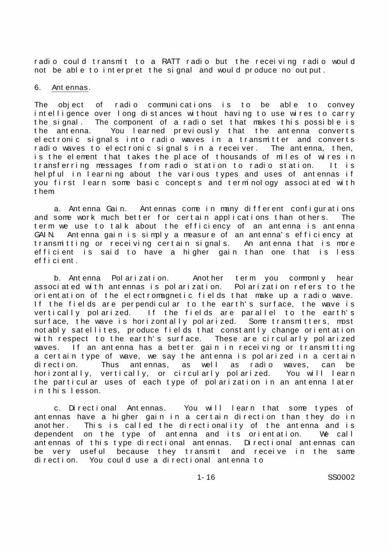
Now that you know the basic theory behind antenna operation youshould learn about the different types of antennas you may need touse in tactical radio communications. Figure 1-13 shows severaldifferent types of antennas and indicates the directionality of each.The next several paragraphs will discuss the abilities andlimitations of these antennas.
Figure 1-13. Types of antennas
1-19 SS0002
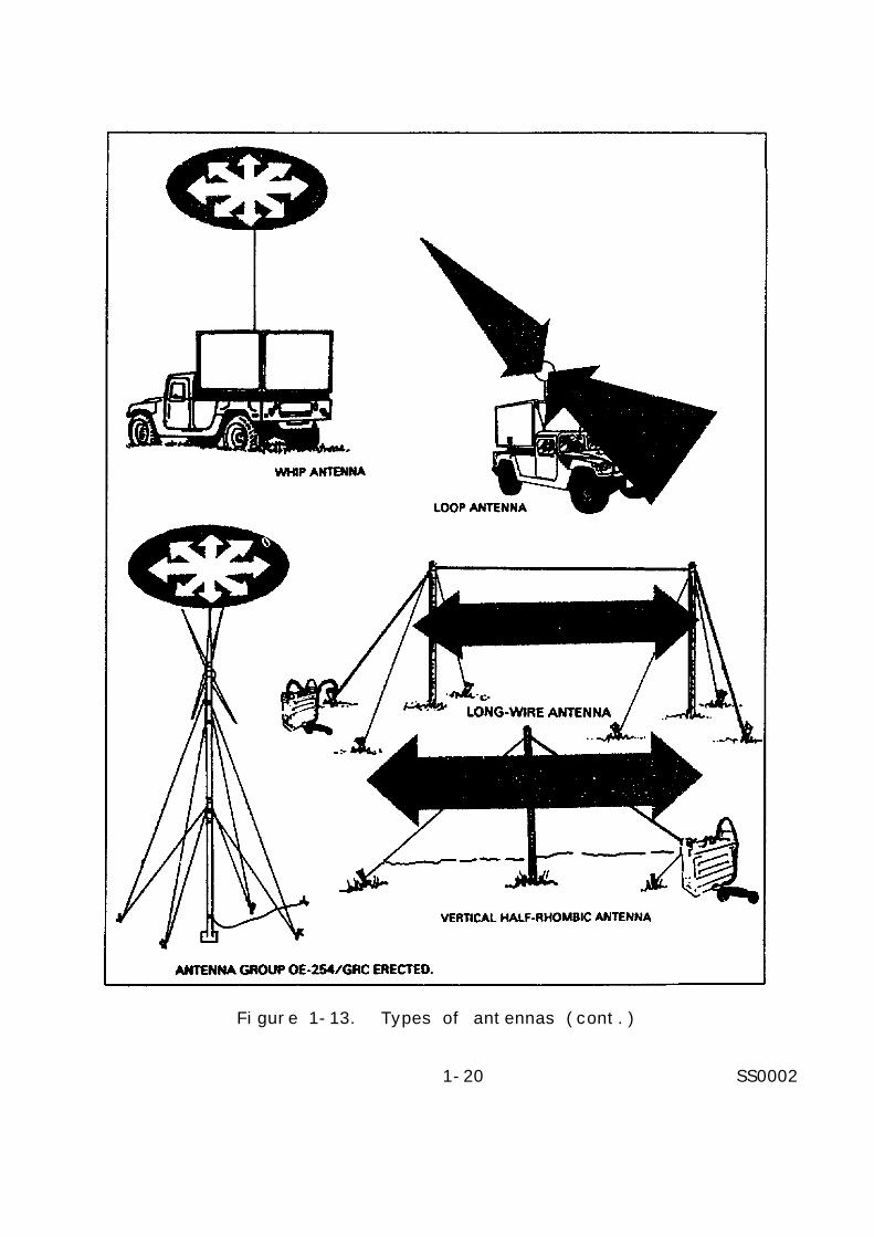
Figure 1-13. Types of antennas (cont.)
1-20 SS0002

Figure 1-13. Types of antennas (cont.)
a. Rhombic Antenna. The rhombic antenna is useful in conductingHF communications between fixed points. With the radio antenna leadattached at one apex and a terminating resistor at the opposite apex,the antenna is unidirectional and has very good directionality bothin the transmit and receive modes. This feature can be useful if youare trying to limit the signal sent to unfriendly forces or preventnoise interference of a nearby RF noise source (e.g., an industrialarea). The drawbacks associated with this antenna are that it isfairly large and not easy to set up. The wires must be the correctlengths, and the azimuth must be properly determined. Since theantenna is fixed, it is difficult to reorient it to a new azimuth tocommunicate with a different radio station.
b. Hertz Antenna. The Hertz or half-wave antenna is a commonconfiguration for field communications. This antenna is also calleda center-fed doublet. You can orient the antenna either horizontallyor vertically and the polarization of the antenna corresponds to theorientation. The antenna is directional, with the primary directionbeing perpendicular to the antenna axis. One drawback of the antennais that it transmits
1-21 SS0002

perpendicular to its axis in all directions. For example, if you aretransmitting a strong signal directly behind you to a rear element,you are also transmitting a strong signal directly in front of you topossible hostile forces. When you construct a Hertz antenna you musttake care to construct it to the proper length for the frequency youare using. Do this using the formulas previously discussed for ahalf-wave antenna. The obvious disadvantage is that the antenna istuned only for a small band of frequencies. Hertz antennas are veryportable and are easy to set up and take down. You can also changethe orientation of a Hertz antenna with minimum difficulty.
c. Marconi Antenna. If you take a vertical half-wave antenna andreplace the lower half with a conducting plane, the upper half willcontinue to radiate as a half-wave antenna even though it is only aquarter wavelength long. This type of antenna is called a Marconi orquarter-wave antenna. The conducting plane mentioned can be theground, a vehicle body, or even a shelter roof. Since it is verticalthe polarization of a quarter-wave antenna is almost always vertical.The whip and the ground plane antennas are typical examples ofMarconi antennas. The obvious advantage of the quarter-wave antennais that it is shorter than the half-wave antenna of the samefrequency. This makes the quarter-wave antenna ideal for portableapplications such as backpack and vehicular mounted radios.
d. Whip Antenna. The whip antenna is the simplest of the Marconifamily of antennas. Some whip antennas are extremely short; muchshorter than a quarter wavelength. These antennas are calledbaseloaded whip antennas and will have a coil attached to the base ofthe whip. The coil contains a conductor of sufficient length to makethe antenna a quarter-wavelength long. Theoretically, the whipantenna is an omnidirectional antenna. When attached to a vehicle,however, the radiation pattern shows a certain directionalitydepending on the placement of the antenna on the vehicle body.Figure 1-14 illustrates this concept. The whip antenna is the mostportable type of antenna and, therefore, the most widely used intactical radio communications.
e. Ground Plane Antenna. If you take a whip antenna and addhorizontal elements to the vertical radiator, the horizontal elementsact as a ground reflector or counterpoise. This configuration iscalled a ground plane antenna. You can use a ground plane antenna onany type of soil because it creates it own reflection. The groundplane antenna is omnidirectional. This makes it ideal forcommunicating with mobile units that do not stay in one place for avery long time. In some configurations, you can tune the groundplane antenna to a certain frequency by changing the length of theradiating and reflecting elements. The broadband omnidirectionalantenna system OE-254 is in common
1-22 SS0002
use today for VHF-FM tactical radio sets. It is an improvement overthe earlier ground plane antennas because it does not have to bereconfigured physically when you change radio frequencies. The OE-254 kit comes with antenna, mast, all supporting equipment needed toset it up, and all electrical connectors needed to operate it withmost tactical radio sets in use today.
Figure 1-14. Directivity of a vehicle-mounted whip antenna
f.Directional Antennas. While omnidirectional communications aregood for communicating with mobile units, they do not provide verygood communications security. Any station within range can pick upthe signal transmitted from this type of antenna. Occasionally youmay want to communicate with another station covertly. You will ofcourse use coded transmissions, but even the fact that you aresending a signal out can give away your position if you are notcareful. In this scenario the safest method of communications is touse a directional antenna. There are three basic types ofdirectional antennas that you can easily employ in a fieldenvironment. They are the long-wire antenna, the vertical half-rhombic antenna, and the V antenna.
The long-wire antenna is simply what the name implies. It is anantenna that you have constructed to a certain number of wave-lengths(using the previous formula). To obtain directionality, you connectthe radio set to one end and terminate the other end to ground with aresistor. You should always remember when choosing terminatingresistors for any antenna that the rating of the resistor should beat least half of the rated output power of the radio transmitter youare using. This will keep you from burning out the resistor. Onceyour long-wire antenna
1-23 SS0002

is configured, you orient it by pointing the terminated end towardthe azimuth of the radio station with which you are communicating.You orient the antenna horizontally and as high off the ground aspossible. The antenna will work as low as three feet from theground, but efficiency will increase as it is raised.
The vertical half-rhombic antenna is a vertically-polarizeddirectional antenna that operates between 30 and 88 MHz. It consistsof two sloping segments, each about two wavelengths long, and ahorizontal segment that acts as a counterpoise (refer to figure1-13). The antenna is easy to transport, set up, and tear down. Youcan also change the antenna azimuth quickly and easily. The use ofthe vertical half-rhombic antenna can not only providedirectionality, but also provide extended range over the OE-254antenna because it sends its energy out in only one direction.
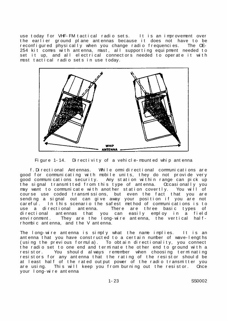
The V antenna is very similar to the rhombic antenna discussedearlier in this lesson. It consists of two horizontal legs connectedin a V with the radio set connected at the apex. The free ends areterminated in the same manner as the long-wire and vertical half-rhombic antennas. The combination of radiation patterns from the twoelements forms a central directional beam that bisects the two legs.Figure 1-15 illustrates the radiation pattern of a V antenna. Thesignal from this antenna is horizontally polarized. This makes theantenna useful in an area where there is much vertically polarized RFinterference.
You can see from this discussion that you can use the V and thevertical half-rhombic antennas to complement each other in areas ofhigh RF noise. TM 11-666 talks in detail about the configuration ofthe V antenna for various frequency ranges, but table 1-3 givesoptimum angles of separation for the antenna legs based on theirlength. Review of TM 11-666 is not required for completion of thissubcourse.
Table 1-3. Leg angle for V antennas
1-24 SS0002
You can see from this table that a longer antenna length provides anarrower beamwidth. This has the advantage of greater directionalityand the disadvantage of requiring greater accuracy in setting theantenna azimuth.
Figure 1-15. Radiation pattern of a V antenna
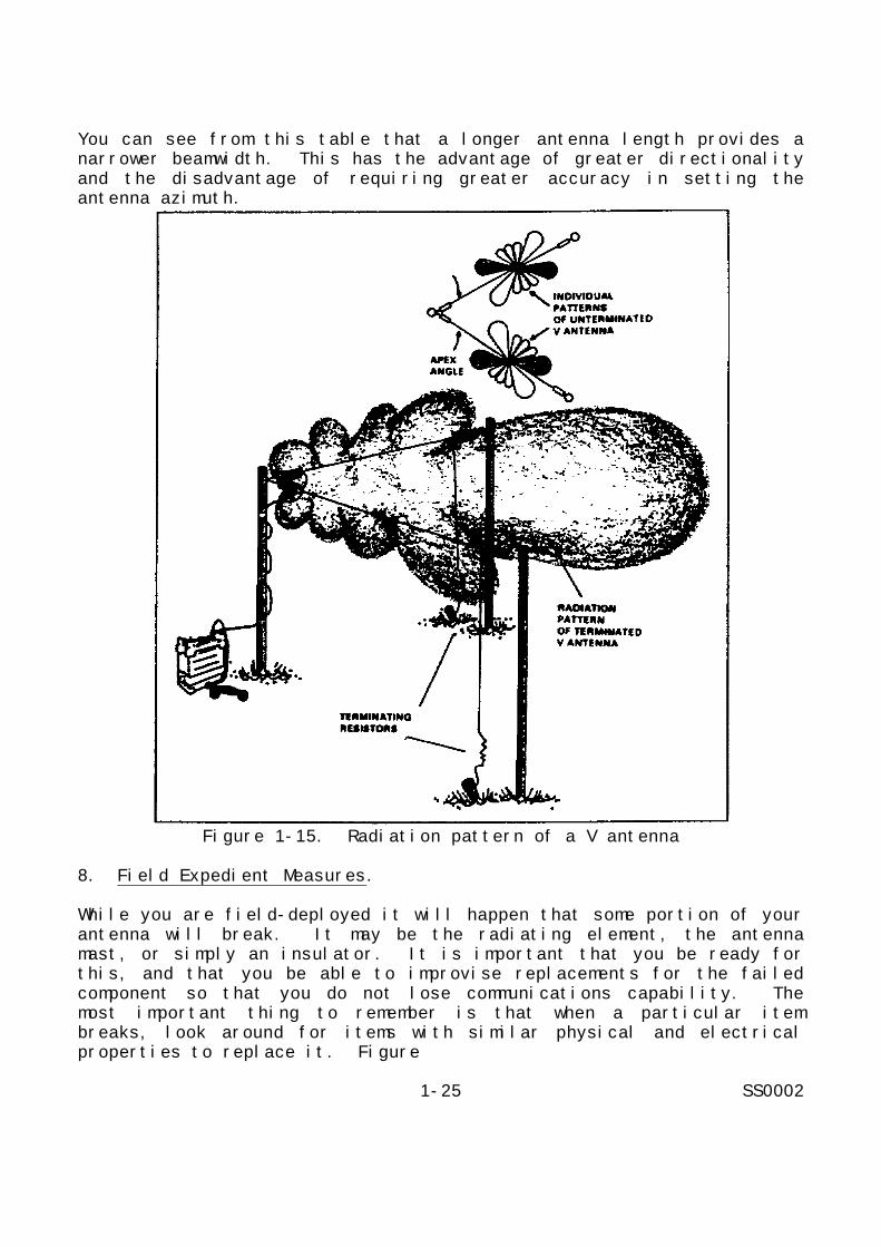
8. Field Expedient Measures.
While you are field-deployed it will happen that some portion of yourantenna will break. It may be the radiating element, the antennamast, or simply an insulator. It is important that you be ready forthis, and that you be able to improvise replacements for the failedcomponent so that you do not lose communications capability. Themost important thing to remember is that when a particular itembreaks, look around for items with similar physical and electricalproperties to replace it. Figure
1-25 SS0002

1-16 shows that a tree makes a very good replacement for a brokenantenna mast as does a wooden pole (e.g., broom handle). You cantake ordinary antenna wire and fabricate almost all the antennas youhave learned about in this section. Remember, the formulas fordetermining the length of your antenna and your field expedient canbe just as good as the original.
Figure 1-16. Field substitutes for antenna supports
Figure 1-17 will give you an idea of the wide variety of items youcan use to replace things like broken insulators. A knife or bayonetcan also serve as a good substitute for a ground stake that has beenlost or broken. You can repair a broken whip antenna by attaching alength of wire to it to make its total length a quarter wavelengthagain. Remember, the best tool to have in an emergency situation isyour imagination.
9. Improvement of Marginal Communications.
Just as you are destined to have equipment failure, so are youdestined to be in positions where communications is only marginal atbest. This may be because of terrain obstructions, interference dueto jamming or other RF noise, or even range limitations of yourequipment. The following paragraphs provide some guidance on what todo when you find yourself in this situation. Interference can becaused by many different things. Electronic jamming, industrialmachinery, air traffic, other radio sets operating in your area, hightension lines, and even solar and
1-26 SS0002

cosmic disturbances can interfere with your radio communications.One way to compensate for this is by checking your radio system forany loose connections and by making sure your radio and antenna areproperly tuned. Sometimes switching to another channel may help, butyou may also lose communications with the station you are trying tocommunicate with.
Figure 1-17. Field improvised insulators
If you can determine the source of the interference you may be ableto use a directional antenna to eliminate some of it. This will onlywork, however, if the interference source and the station you arecommunicating with are on different azimuths.
Determining the source of interference may also tell you how theinterfering signal is polarized. Most man-made RF noise isvertically polarized. Using a horizontally polarized antenna can doa lot to lessen the effect of interference. Likewise, in a forestvertically polarized waves tend to be absorbed by the trees more thanhorizontally polarized waves. RF interference caused by aircraft orcommercial radio and television transmissions, on the other hand, isusually horizontally polarized. You should use a verticallypolarized antenna if you are experiencing interference from one ofthese sources.
If you are having trouble communicating due to range fading, adirectional antenna may help. It can boost your signal in thedirection of the station you are talking to and will also increaseyour receiver sensitivity.
1-27 SS0002

If none of the previous measures improve your communications, youshould also try moving your antenna or raising or lowering yourantenna. If you are still having trouble communicating there may benothing to do but move to a different location and try again.
10. Summary.
In this lesson you have learned the basics of radio theory. You havelearned how a basic radio transmitter and receiver work and howamplitude modulation differs from frequency modulation. You havealso learned about the different types of antennas used in tacticalradio communications and how to select and use the best antenna for agiven job. In the next lesson you will learn about the differenttypes of tactical radios in use and how to select a certain radio fora certain communications task.
1-28 SS0002

LESSON 1
PRACTICE EXERCISE
The following items will test your grasp of the material covered inthis lesson. There is only one correct answer for each item. Whenyou complete the exercise, check your answer with the answer key thatfollows. If you answer any item incorrectly, study again that partof the lesson which contains the portion involved.
Situation: You are conducting training on basic radio and antennatheory.
1. Which of the following types of waves is most likely to beaffected by sunspots?
A. Sky-waves.B. Ground waves.C. Direct waves.D. Line of sight waves.
2. Which of the following statements about AM/SSB radios is NOTtrue?
A. AM/SSB provides greater reliability than AM/DSB.B. AM/SSB systems are larger and heavier than AM/DSB systems.C. AM/SSB systems provide increased output without increasing
antenna voltage.D. AM/SSB systems can operate over longer ranges without loss
of intelligence due to selective fading.
3. You are constructing a long-wire antenna three wavelengths longto communicate on a channel frequency of 29.274 MHz. How longshould you make your antenna?
A. 50.0 feet.B. 50.4 feet.C. 100.0 feet.D. 100.8 feet.
4. You are in the field and one of your antenna insulators hasbroken. Which of the following items will make the bestreplacement?
A. A shoelace.B. A tree branch.C. A plastic shirt button.D. The top from a soft drink can.
1-29 SS0002

LESSON 1
PRACTICE EXERCISE
ANSWER KEY AND FEEDBACK
Item Correct Answer and Feedback
1. A. Sky-waves.
Since sky-waves propagate by reflecting off the ionosphere,any disturbance in the ionosphere can cause a disturbance ina sky-wave transmission. The 11-year regular variations inthe ionosphere are caused by sunspots, and these variationswill affect sky-wave transmission. Since the other types ofwaves are not affected by the ionosphere, they should not beaffected by sunspots. (page 1-6, para 2b(1)(d)).
2. B. AM/SSB systems are larger and heavier than AM/DSBsystems.
In fact, one advantage of AM/SSB systems is that, becausethey electronically suppress one sideband and the Carrier,less energy is required for the same power transmission.This means that power supplies do not have to be as large,making the overall radio smaller and lighter than acomparable AM/DSB system. (page 1-11, para 4b(2)).
3. C. 100.0 feet.
Three wavelengths is six half-wavelengths. Using the formulafor long-wire antennas gives:
4. C. A plastic shirt button.
In order of preference, the items to use would be the button,then the tree branch (if it was not still green), then theshoelace. The can top or a green tree branch would not workbecause they would conduct too much current to the ground.(page 1-26, para 8).
1-30 SS0002

LESSON 2
TACTICAL CONTINUOUS WAVE AND VOICE RADIO EQUIPMENT
CRITICAL TASKS: 01-5878.04-0005,01-5778.07-0003, 01-5778.07-0007
OVERVIEW
LESSON DESCRIPTION:
In this lesson you will learn the different types of tactical radiosets currently in use and how to select a particular set for a givencommunications task.
TERMINAL LEARNING OBJECTIVE:
ACTIONS: a. Identify the tactical frequency modulation, amplitudemodulation/double sideband, and amplitudemodulation/single sideband radio sets in the field.
b. Determine which tactical radio set best meets aspecific communications requirement.
c. Select tactical radio sets that are compatible forpoint-to-point, system, and net operation.
CONDITION: You will be given information from this lesson.
STANDARD: To demonstrate competency of the terminal learningobjective, you must achieve a minimum score of 70% on thesubcourse examination.
REFERENCES: The material contained in this lesson was derived fromthe following publications: FM 24-18 and TC 24-24.
INTRODUCTION
The rapid changes in communications technology are constantlybringing new and better equipment to the market for use in the field.This lesson will present some of the equipment currently used as wellas equipment which is being phased-out. Even though a piece ofequipment may be outdated, you may still run across it in reserveunits or you may have occasion to use a piece as a backup to a failedmodern unit. It is important, therefore, that you know how thisolder equipment operates and what its capabilities are. Since thislesson is merely an overview and is in no way a complete technicaldescription of any piece of equipment, you are encouraged to read thetechnical
2-1 SS0002
manuals on each piece of equipment in order to become thoroughlyfamiliar with its capabilities. However, review of these technicalmanuals is not required for completion of this subcourse.
1. Transmitting Set AN/PRT-4, AN/PRT-4A.
TM 11-5820-549-12 details this equipment. The AN/PRT-4 and 4A arehand-held, low-power FM transmitters. These sets are generallyconsidered obsolete and are no longer in much use. They transmitover a relatively short distance in the low VHF region (47 to 57MHz). They were formerly used primarily at the squad and platoonlevel for the leader to communicate with unit personnel.
2. Receiving Set AN/PRR-9.
TM 11-5820-549-12 details this equipment. This is the receiver thatwas used in conjunction with the AN/PRT-4 transmitter in the squad orplatoon. It mounts on the soldier's helmet or webbing and has anearphone jack for quiet reception. As with the AN/PRT-4, thisequipment is obsolete.
3. Radio Sets AN/PRC-25, AN/VRC-53, and AN/GRC-125.
TM 11-5820-398-12 (PRC-25) and TM 11-5820-498-12 (VRC-53, GRC-125)details these sets. This family is the earliest group of FMtransmitter-receiver radio sets still in use. All three versionsutilize the RT-505 transmitter-receiver operating in the lower VHFband (30 to 52.95 MHz and 53 to 75.95 MHz). The PRC-25 is a portablemanpack version. The VRC-53 adds amplifier OA-3633 to make avehicular-based unit, and the GRC-125 is a portable or vehicularbased model. All three configurations are used for short-rangecommunications. This family of radio sets has no secure transmissioncapability.
4. Radio Sets AN/PRC-77, AN/VRC-64, and AN/GRC-160.
TM 11-5820-667-12 details these sets. This family of radio sets isreplacing the PRC-25, VRC-53, and GRC-125 series respectively. Thetransmission characteristics are exactly the same as the earlierradio sets. The difference is that the newer sets use transmitter-receiver RT-841 which is completely transistorized. Another featureincorporated into the new sets is the capability of secure voicetransmission using the VINSON device.
5. AN/VRC-12 Family of Radio Sets.
These sets and their components are detailed in TM 11-5820-401-12.The radio sets in the AN/VRC-12 family are short-range vehicular andfixed radio sets designed for general tactical use. They provide FMvoice communications and can be used with
2-2 SS0002

secure voice and digital data equipment using the X MODE facility.Two of the sets (AN/VRC-45 and AN/VRC-49) have retransmissioncapability. The radio sets of the AN/VRC-12 family will net witheach other and with other FM radio equipment operating in the 30 to75.95 MHz frequency range. Each of the eight configurations in thisfamily is made up of a combination of receiver-transmitters RT-246/VRC and RT-524/VRC and receiver R-442/VRC along with supportequipment.
a. Receiver-transmitter RT-246/VRC and RT-524/VRC. These tworeceiver-transmitters are the heart of the AN/VRC-12 family ofradios. They operate in two bands; Band A - 30 to 52.95 MHz, andBand B - 53 to 75.95 MHz. They are capable of transmission up toabout 41 kilometers (km). Each member of the AN/VRC-12 familycontains at least one of these units. The primary differencesbetween the two units are that the RT-246 has ten automatic channelpresets and the RT-524 has a built-in loudspeaker.
b. Receiver R-442/VRC. This receiver is used in several of theAN/VRC-12 configurations to allow monitoring one net whiletransmitting in another. The R-442 operates in the same frequencyrange as the RT-246 and RT-524.
(1) AN/VRC-12. This configuration includes one RT-246, one R-442, and two antennas. You can use this configuration to monitor onenet while you conduct communications in another. You can easilyswitch transmitting frequencies of the R-246 to transmit in the R-442's net.
(2) AN/VRC-43. This configuration consists of one RT-246 andone antenna and it is used for communications in a single radio net.
(3) AN/VRC-44. This configuration consists of one RT-246, twoR-442s, and two antennas. With this set you can communicate in onenet and monitor two additional nets. As with the VRC-12, you canchange transmitting frequency on the RT-246 and transmit into eitherof the other two nets.
(4) AN/VRC-45. This configuration consists of two RT-246s, twoantennas, and a C-2299/VRC Retransmission Cable Kit. You should usethis configuration to provide retransmission facilities for twostations that are too far apart to talk to each other directly. Youcan also use this set to retransmit information from one net intoanother net by tuning the two RT-246s to different frequencies.
(5) AN/VRC-46. This configuration uses one RT-524 and oneantenna and is essentially identical in function to the AN/VRC-43.
2-3 SS0002

(6) AN/VRC-47. This configuration uses one RT-524, one R-442,and two antennas. It functions the same way as the AN/VRC-12.
(7) AN/VRC-48. This set consists of one RT-524, two R-442s,and two antennas. It functions the same way as the AN/VRC-44.
(8) AN/VRC-49. This configuration consists of two RT-524s, twoantennas, and the C-2299/VRC. It serves the same retransmissionfunctions as the AN/VRC-45.
All the AN/VRC-12 family configurations are secure voice capable.You can secure the sets using either VINSON (KY-57) or NESTOR (KY-38)security devices.
6. Radio Set Control AN/GSA-7.
TM 11-5135-15 details this equipment. The AN/GSA-7 is an electronicswitching device. You use it to interface FM radio equipment withlocal push-to-talk wire telephone circuits. The GSA-7 is the basisof the Net Radio Interface (NRI) system. The unit acts as anautomatic keying device so that when a remote telephone operator keyshis telephone set he also keys the transmitter of the FM radio set.This allows his wire telephone message to transmit over the FMfrequency to a receiver that can also be attached to another GSA-7 toconvey the message into another wire telephone net at a remote site.You can control a radio set with the GSA-7 from as far away as 16 km(7.3 miles).
7. Control Group AN/GRA-6.
TM 11-5038 details this equipment. Occasionally you may want tolocate your radio transmitter in a site where communications aregood, but the site does not offer a good tactical position. Whenthis happens the best thing to do is set the radio up so you canoperate it remotely. The GRA-6 is the piece of equipment that allowsyou to do this. The GRA-6 consists of a local and remote unit usedat the radio site and the remote control site respectively. The twounits are connected by field wire and can be separated by up to 3.2km or 1.5 miles.
8. Radio Set Control Group AN/GRA-39B.
TM 11-5820-477-12 details this equipment. The GRA-39B is anotherremote control set similar to the GRA-6. It also is used with FMradio sets and has a range of 3.2 km. The principal differencebetween the GRA-39B and the GRA-6 is that the 39B is fullytransistorized and the 6 is not.
2-4 SS0002
9. Retransmission Cable Kit MK-456A/GRC.
This kit is used with the AN/PRC-25 and AN/PRC-77 series of radiosfor retransmission. You can also use it with the AN/VRC-12 series ifthe standard C-2299/VRC kit is unavailable.
10. Radio Set AN/GRC-19.
TM 11-5820-295-10 details this equipment. The AN/GRC-19 is a medium-power voice and continuous wave radio set designed for vehicularinstallations. It forms the central unit for several of the olderRATT sets. The GRC-19 is being phased-out of use and replaced withthe newer GRC-106 radio set. You can also use the GRC-19 to performretransmission functions. Both transmitter and receiver operate inthe HF band. The transmitter operates between 1.5 and 20 MHz, andthe receiver operates between 0.5 and 32 MHz. The AN/GRC-19 operatesin AM/DSB mode.
11. Radio Set AN/GRC-106.
TM 11-5820-520-12 details this equipment. As stated previously, theAN/GRC-106 is replacing the AN/GRC-19 in its mobile retransmissionrole. It is also the central unit for the newer family of radioteletypewriter sets currently in use. The GRC-106 operates in the HFband between 2.0 and 29.999 MHz and uses the AM/SSB mode. There aretwo basic configurations of this equipment, the GRC-106 and GRC-106A.The former uses receiver-transmitter RT-662/GRC which has a channelspacing of 1 kHz. The A variation uses receiver-transmitter RT-834/GRC which has channel spacing of 100 Hz. You can see from this thatthe A variation has ten times as many channels available as thestandard GRC-106. The AN/GRC-106 has both voice and CW capability.
12. Radio Set AN/FRC-93.
TM 11-5820-554-15 details this equipment. The FRC-93 is a commercialtype of AM/SSB (upper or lower) radio set adapted for military use.You can also perform CW communications using the FRC-93. The radioset operates in two regions of the HF band, from 3.4 to 5.0 MHz andfrom 6.5 to 30 MHz. This type of radio set uses crystal sets fortuning.
13. Radio Set AN/PRC-74.
TM 11-5820-590-12 and TM 11-5820-590-12-1 details this equipment.The AN/PRC-74 is a low-power, transistorized AM/SSB/USB radio setdesigned for voice and CW communications. The PRC-74 is configuredas a manpack and is primarily designed for communications in areaswhere LOS communications is not possible due to
2-5 SS0002
terrain or other obstructions. The AN/PRC-74 comes in fourvariations: basic, A, B, and C. The basic and A versions operatebetween 2.0 and 11.999 MHz. The B and C versions extend the upperfrequency limit to 17.999 MHz. The AN/PRC-74 adds the versatility ofbeing able to communicate with remote sites that you could notcommunicate with using the AN/PRC-25 or 77 series of FM radios.
14. Radio Set AN/PRC-70.
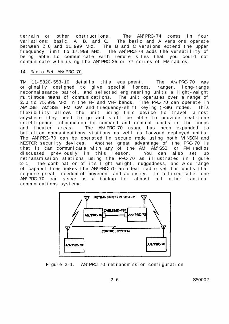
TM 11-5820-553-10 details this equipment. The AN/PRC-70 wasoriginally designed to give special forces, ranger, long-rangereconnaissance patrol, and selected engineering units a light-weightmultimode means of communications. The unit operates over a range of2.0 to 75.999 MHz in the HF and VHF bands. The PRC-70 can operate inAM/DSB, AM/SSB, FM, CW, and frequency-shift keying (FSK) modes. Thisflexibility allows the unit using this device to travel almostanywhere they need to go and still be able to provide real-timeintelligence information to command and control units in the corpsand theater areas. The AN/PRC-70 usage has been expanded tobattalion communications stations as well as forward deployed units.The AN/PRC-70 can be operated in secure mode using both VINSON andNESTOR security devices. Another great advantage of the PRC-70 isthat it can communicate with any of the AM, AM/SSB, or FM radiosdiscussed previously in this lesson. You can also set upretransmission stations using the PRC-70 as illustrated in figure2-1. The combination of its light weight, ruggedness, and wide rangeof capabilities makes the AN/PRC-70 an ideal radio set for units thatrequire great freedom of movement and activity. In a fixed site, oneAN/PRC-70 can serve as a backup for almost all other tacticalcommunications systems.
Figure 2-1. AN/PRC-70 retransmission configuration
2-6 SS0002

15. Summary.
This lesson has introduced you to the various pieces of equipmentused in tactical radio communications, along with the uses for andcapabilities of each piece of equipment. In the next lesson you willlearn the basic procedures of voice communication over tactical radiochannels.
2-7 SS0002

THIS PAGE IS INTENTIONALLY LEFT BLANK.
2-8 SS0002

LESSON 2
PRACTICE EXERCISE
The following items will test your grasp of the material covered inthis lesson. There is only one correct answer for each item. Whenyou complete the exercise, check your answer with the answer key thatfollows. If you answer any item incorrectly, study again that partof the lesson which contains the portion involved.
Situation: You are responsible for managing communications for afield exercise.
1. You are using the AN/VRC-43 set to communicate with a specialforces unit that is using the AN/PRC-70 set. The unit movesover a large hill, cutting off communications. Which of thefollowing radio sets should you use to reestablishcommunications with the unit?
A. AN/VRC-46.B. AN/GRC-106.C. AN/GRC-125.D. AN/GRC-160.
2. While the special forces unit is still on the other side of thelarge hill, it experiences a failure in its AN/PRC-70 set.Which of the following sets can the unit use to reestablishcommunications with you?
A. AN/PRT-4A.B. AN/PRC-25.C. AN/PRC-74.D. AN/PRC-77.
3. You are directed to set up a net radio interface using yourAN/VRC-12 series radio. Which of the following pieces ofauxiliary equipment should you use to accomplish this?
A. AN/GSA-7.B. AN/GRA-6.C. AN/GRC-19.D. AN/GRA-39B.
2-9 SS0002

THIS PAGE IS INTENTIONALLY LEFT BLANK.
2-10 SS0002

4. While you are in your exercise area, some civilian trucks withcitizens' band radios enter your exercise area. Which radio setshould you use to inform them that they are in a restrictedarea?
A. AN/VRC-12.B. AN/PRC-25.C. AN/FRC-93.D. AN/GRC-160.
2-11 SS0002

LESSON 2
PRACTICE EXERCISE
ANSWER KEY AND FEEDBACK
Item Correct Answer and Feedback
1. B. AN/GRC-106.
Since communications was cut off as the unit moved over thehill, you have an indication that the direct path ofcommunication is no longer available. Most VHFcommunications take place along the direct path, so you musttry another propagation path to communicate with the unit.The AN/GRC-106 is an HF radio, so it can use the sky-wavetransmission path. The AN/PRC-70 has the capability tocommunicate in both HF and VHF bands and using both AM and FMmodes. This feature makes it capable of taking advantage ofwhatever communications paths and equipment are available.(page 2-5, para 11).
2. C. AN/PRC-74.
The unit is still out of the range of a VHF line-of-sightradio. If their AN/PRC-70 fails, they must use some other HFAM radio set. The AN/PRC-74 is the only choice that matchesthose criteria. (page 2-5, para 13).
3. A. AN/GSA-7.
The AN/GSA-7 is a switching device designed to provide NRIfor AN/VRC-12 series radios. The AN/GRA-6 and GRA-39B areboth remote radio control devices and the AN/GRC-19 is an AMradio set. (page 2-4, para 6).
4. C. AN/FRC-93.
The AN/FRC-93 is a military derivative of the commercialcitizens' band radio. The other choices are all VHF radiosand would not be compatible with the truck's radios. (page2-5, para 12).
2-12 SS0002

LESSON 3
TACTICAL RADIO VOICE OPERATION
CRITICAL TASKS: 01-5878.04-0005,01-5778.07-0003, 01-5778.07-0007
OVERVIEW
LESSON DESCRIPTION:
In this lesson you will learn the basic procedures for operating avoice radio including: operating rules, phonetic alphabet, correctpronunciation, procedure sign (PROSIGN) usage, authenticationprocedures, and operations within a radio network.
TERMINAL LEARNING OBJECTIVE:
ACTIONS: a. Describe the necessity for using proper radiotelephoneprocedures.
b. Define the uses of the phonetic alphabet and thenumerical pronunciation.
c. Describe the use and meaning of the more commonly usedPROSIGNs.
d. Define the necessity for and give examples ofauthentication.
e. Describe the procedures for opening and closing a netusing authentication.
CONDITION: You will be given information from this lesson.
STANDARD: To demonstrate competency of the terminal learningobjective, you must achieve a minimum score of 70% on thesubcourse examination.
REFERENCES: The material contained in this lesson was derived fromthe following publications: FM 11-32, FM 11-50, FM 24-18,and SOI KTV 1600 C Supplemental Instructions.
INTRODUCTION
The tactical effectiveness of any communications equipment is nogreater than the skill of the operators. By the same token, the mostefficient communications within a net or command is
3-1 SS0002

attained when the operators habitually use proper procedures intransmitting and receiving messages. This lesson will introduce youto the basic procedures and protocol associated with tactical radiocommunications.
1. Preparations.
Before attempting any communication, there are certain preparationsthat any operator should perform. These preparations ensure that theequipment is properly set up, that the operator is familiar with theoperation of the equipment, and that the operator is familiar withthe signal operation instructions and proper communicationsprocedures.
2. Equipment Checkout.
Before operating any piece of radio equipment you should be certainit is properly configured and that you are familiar with itsoperation. The equipment technical manual is the best place to beginwhen you check an equipment configuration. The technical manual willhave directions, diagrams, and procedures for aligning and operatingthe equipment. If the technical manual is not available, you shouldat least have some sort of abbreviated checklist that you can use toverify the setup of your system. Things to check should includetuning, power settings, ensuring all connections are tight andinsulated, and ensuring that all components of your communicationssystem can handle the power output of the transmitter.
3. Signal Operation Instructions.
The SOI and the standing operating procedures (SOPs) containinstructions pertaining to radio communications. The SOP is astandard document that governs the routine signal operations of aunit. It should include such items as communications systemspriorities and general guidance on communications protocol. The SOIis a unit-specific document that deals with actual communicationsorganizations in much more detail. The SOI contains such informationas organization of stations into radio nets, assigning of net controlstations (NCSs), and assigning of primary and alternate operatingfrequencies for each net. The SOI also provides guidance onauthentication procedures and other communications security measures.FM 24-16 provides additional information about the SOP and FM 24-35provides additional information on the SOI. Review of these manualsis not required for completion of this subcourse.
4. Phonetic Alphabet.
If radio communication was as clear and understandable as face-to-face communication, there would be no need to use special
3-2 SS0002

procedures when talking on the radio. Radio communications, however,can vary widely from extremely clear to barely intelligible. Becauseof this, there are certain rules of pronunciation when you aretalking on a radio circuit. The phonetic alphabet employs theserules. Many times during radio communications you may need to sayletters or numbers in the course of conversation. For example, callsigns (which will be discussed later in this lesson) are made up ofletters and numbers. If you only pronounce the name of the letter ornumber, the operator on the other end could confuse it with anotherletter or number. Spoken, the letter B sounds very much like P, V,or D. Likewise, the numbers nine and five often sound alike. Thephonetic alphabet was designed to eliminate this confusion. Eachletter and number has a distinct and understandable word associatedwith it. Tables 3-1 and 3-2 list the letters and numbers and theirphonetic pronunciation.
Table 3-1. Phonetic alphabet
As you can see, in each instance the emphasized syllable isunderlined. For example, the letters BPV would be pronounced "BravoPapa Victor." The use of the phonetic alphabet makes the lettersclear to the receiving operator.
5. Procedure Words and Procedure Signs.
Along with being understood in radio transmissions, another veryimportant point is that messages be as brief as possible. Lengthymessages run the risk of becoming garbled at some point and losingthe meaning of the message. In today's world of electroniccountermeasures and electronic homing devices, the less time a radiostation is transmitting, the less likely it is
3-3 SS0002

to be discovered and targeted by enemy forces. In order tostandardize certain common phrases used in radio transmissions, a setof procedure words (PROWORDs) has been devised and is recognized as astandard in radio communications. The same factors that make itdesirable for spoken messages to be short and concise also apply totypewritten messages. Most PROWORDs have a corresponding PROSIGN tohelp abbreviate teletype messages. Table 3-3 lists some commonPROWORDs and their corresponding PROSIGNs and meanings. Where noPROSIGN is listed there is not a common PROSIGN associated with thatPROWORD.
Table 3-2. Number pronunciation guide
Table 3-3. PROWORDs and PROSIGNs
3-4 SS0002

Table 3-3. PROWORDs and PROSIGNs (cont.)
3-5 SS0002

Table 3-3. PROWORDs and PROSIGNs (cont.)
3-6 SS0002

Table 3-3. PROWORDs and PROSIGNs (cont.)
3-7 SS0002

Table 3-3. PROWORDs and PROSIGNs (cont.)
3-8 SS0002

Table 3-3. PROWORDs and PROSIGNs (cont.)
3-9 SS0002
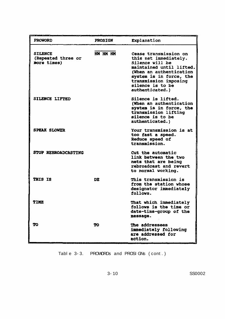
Table 3-3. PROWORDs and PROSIGNs (cont.)
3-10 SS0002

Table 3-3. PROWORDs and PROSIGNs (cont.)
3-11 SS0002

Table 3-3. PROWORDs and PROSIGNs (cont.)
When you are conducting radio communications it is important that youand your operators use the proper PROWORDs and PROSIGNs so that yourmessages will be clear and concise to the receiving station.
6. Call Signs.
In radio communications it is not only important to know what is in amessage, but it is also important to know who sent the message. Asystem of CALL SIGNS has been developed so that stations can identifythemselves and to the stations they are talking. A call signnormally consists of a three-character letter-number-letter basiccall sign followed by a two-digit suffix. If the command issuingcall signs has more than 99 users, an expander letter may appearafter the suffix. This total of five or six characters is called thecomplete call sign. The last letter of the basic call sign plus thetwo suffix numbers (and expander letter if applicable) is called theabbreviated call sign and should be used except when entering a netor when requested by the net control station. The following is anexample of a complete and abbreviated call sign.
Complete call sign - C 3 T 8 5
Abbreviated call sign - T 8 5
Always pronounce call signs phonetically. For example, the abovecomplete call sign should be pronounced "Charlie tree tango ait fife"and the abbreviated call sign "Tango ait fife." Your command willissue call signs in its SOI. Each call sign will have a certainduration, usually 24 hours.
3-12 SS0002
7. Authentication.
You have many means of Secure communications at your disposal. It isnot unreasonable to suspect, however that an enemy might somehow beable to break into your net and provide misinformation or give falseorders. The SOI provides a transmission authentication system toprevent this. The only authentication systems authorized for use arethose produced by the National Security Agency (NSA) and provided inyour SOI supplement. The SOI will also define the period of validityfor each authentication system. There are two types ofauthentication: challenge and reply authentication and transmissionauthentication. You should conduct authentication on your net whenany of the following circumstances occur.
a. When any station suspects imitative deception on any circuit.For example, when contacting a station following one or moreunsuccessful attempts to contact that station.
b. When any station is challenged or requested to authenticate.This is not to be interpreted as requiring stations to break animposed silence for the sole purpose of authenticating.
c. When directing radio silence, listening silence, or requiringa station to break an imposed silence (this requires the use oftransmission authentication).
d. When transmitting contact and amplifying reports in plainlanguage.
e. When transmitting operating instructions that affect themilitary situation. For example, closing down a station or watch,changing frequency other than normal scheduled changes, directingestablishment of a special communications guard, requesting artilleryfire support, and directing relocation of units.
f. When transmitting a plain language cancellation.
g. When making initial radio contact or resuming contact afterprolonged interruptions.
h. When transmitting to a station that is under radio listeningsilence.
i. When authorized to transmit a classified message in the clear.
j. When forced, because of no response by the called station, tosend a message in the blind (transmission authentication).
3-13 SS0002

8. Challenge and Reply.
Whenever possible, you should use challenge and reply authenticationas it can validate both the transmitting and receiving stations.Figure 3-1 is a reproduction of the challenge and reply andtransmission authentication tables. Refer to this figure in thefollowing discussion of authentication procedures. When two stationsestablish radio contact, the station being called should always issuethe first challenge. This prevents an enemy from entering your netjust to get a valid authentication to use in another net. When thecalled station has challenged and the calling station has replied,the calling station should challenge in order to also validate thecalled station. The following paragraphs detail the challenge andreply process. For illustration purposes, assume that station M21 iscalling station M35.
M21 issues the call "Mike tree fife, this is mike too wun, over."This establishes the identities of both the calling and the calledstations.
M35 must now issue an authentication challenge. Looking at thechallenge and reply system, he chooses a letter from the far leftcolumn. This is the line indicator column. He then chooses anotherletter from the row indicated by the first letter he chose. Thesetwo letters make up the challenge. Thus, his transmission would be"Mike too wun, this is mike tree fife, authenticate delta golf,over." M35 has chosen delta and golf as his two letters tochallenge.
M21 must now reply to the challenge and issue a challenge of his own.To reply, he must have the same table as M35. He looks up the letterDelta in the left-hand column. He then looks up the letter Golf inDelta's row (row 4 in this case). His reply should be the letterdirectly beneath Golf on the table. In this case it would be Bravo.He then chooses two different letters to issue as a counter challengeto M35. His transmission should be "Mike tree fife, this is mike toowun, I authenticate bravo, authenticate yankee victor, over."
M35 must now respond to M21's challenge. He looks up yankee on hisauthentication table, and then finds victor in yankee's row. Sinceyankee is the last row on the table he gets the reply from the firstrow on the table as if it wrapped around. His reply letter, then, istango, and his transmission is "Mike too wun, this is mike tree fife,I authenticate tango, over." At this point, both stations haveauthenticated and they may continue to communicate and pass whatevertraffic they need to pass.
3-14 SS0002

Figure 3-1. Authentication tables
3-15 SS0002

9. Transmission Authentication.
You should only use transmission authentication when the station youare calling cannot answer because of some problem or silencecondition that has been imposed. The transmission authenticationsystem is based on the second table in figure 3-1. The tableconsists of 40 numbered columns of five, two-character combinations.Each station will be assigned certain columns to use if transmissionauthentication is necessary. When you need to use this system, youtake the first column you are assigned and use the first two-character combination in that column that you have not already used.Those two characters then become the authentication for the message.Once used, you cross out the particular authentication code so thatyou do not reuse it. If you need to send another transmissionauthentication, you use the next code in the column. For example,you are assigned column 33 and have already sent two transmissionauthentication messages. Your next transmission authentication codewould be OX. Your authenticated transmission should be "(Call sign),this is (your call sign), authentication is oscar xray, (yourmessage), out." You would not end a transmission authenticatedmessage with "over," because that would imply that the other stationshould reply. If the other station could reply, you should usechallenge and reply authentication instead.
10. Radio Nets.
A group of radio stations that communicate on the same frequency iscalled a network or net. Radio stations are generally divided intonets according to the function that each station serves within thecommand. Figure 3-2 shows a typical HF operations voice net andfigure 3-3 shows a VHF tactical employment division commandoperations net. The station in charge of maintaining the net iscalled the NCS and is usually a station in a superior unitcommunicating with stations in one or more subordinate units. Eachstation on a particular net will have its own unique call sign. Thenet will also have a call sign which is the basic call sign of theNCS. Thus, for a net whose NCS is A6V58, the net call sign would beA6V. Nets will be assigned on a command level, along with call signsfor each net station.
11. Opening a Net.
The NCS is responsible for opening and closing the net. Normallyupon initial opening or reopening of the net the NCS will initiateauthentication procedures. The following paragraphs detail thisprocess.
3-16 SS0002

Figure 3-2. Typical HF operations voice net
a. The NCS will call the stations on the net using the net callsign and will issue the first authentication challenge using thechallenge and reply system.
b. The station with the first call sign in alphabetical orderwill answer the NCS's call and reply to the challenge. He will thenissue a challenge to the NCS.
c. The NCS will reply to the first station's challenge and issuea second challenge.
d. The station with the next alphabetical call sign will reply tothe NCS's second challenge and issue a challenge of his own.
e. The station with the third alphabetical call sign will replyto the challenge issued by the second station and will issue achallenge to the fourth station.
3-17 SS0002

Figure 3-3. Tactical employment division command operationsnet VHF/FM
f. This process will continue until the last station inalphabetical order has replied to a challenge. The last station willnot issue a challenge of his own.
g. Once all stations have authenticated, the NCS will issueinstructions on the operation of the net.
12. Closing a Net.
As in opening a net, the NCS is also responsible for closing the net.When opening the net you recall that all stations were required toauthenticate. When you close down a net, however, only the stationordering the net to close is required to authenticate. This isbecause the net will not be operating and it is
3-18 SS0002

only necessary to determine if the order to close down is necessary.The procedure for closing the net is outlined in the followingparagraphs.
a. The NCS calls the net and issues the order to close down thenet.
b. The first alphabetical station calls the NCS and issues anauthentication challenge.
c. The NCS replies to the authentication challenge.
d. The stations, in alphabetical order, will call the net andacknowledge the order to shut down.
e. Once all stations have receipted the order, stations may shutdown.
13. Summary.
In this lesson you have learned the basic organization and proceduresfor operating voice tactical radios. The next lesson will introduceyou to radio teletypewriter equipment and procedures.
3-19 SS0002

THIS PAGE IS INTENTIONALLY LEFT BLANK.
3-20 SS0002

LESSON 3
PRACTICE EXERCISE
The following items will test your grasp of the material covered inthis lesson. There is only one correct answer for each item. Whenyou complete the exercise, check your answer with the answer key thatfollows. If you answer any item incorrectly, study again that partof the lesson which contains the portion involved.
Situation: You are the NCS for a communications exercise. Use theauthentication tables in figure 3-1 in answering the following items.
1. Which of the following documents should you consult to determinethe assigned call signs for the exercise?
A. The SOI.B. The SOP.C. FM 11-32.D. FM 24-18.
2. You are opening your net using authentication. You issue thechallenge "Authenticate Juliett Victor." What reply do youexpect?
A. "I authenticate Tango."B. "I authenticate Bravo."C. "I authenticate Foxtrot.”D. "I authenticate Juliett Victor as Tango."
3. You are assigned column six on the transmission authenticationtable. What authentication will you use to order radio silenceon your net?
A. Alfa Alfa.B. Charlie Kilo.C. Golf Uniform.D. Six Alfa Alfa.
4. You are in the middle of a transmission and realize that youhave made a mistake and passed an incorrect piece of data. WhatPROWORD should you use to indicate this to the rest of the net?
A. Break.B. Correction.C. I say again.D. Do not answer.
3-21 SS0002
LESSON 3
PRACTICE EXERCISE
ANSWER KEY AND FEEDBACK
Item Correct Answer and Feedback
1. A. The SOI.
The SOI contains unit-specific information pertaining tocommunications. It will contain call signs, authenticationtables, and any special instructions concerningcommunications within your unit. (page 3-2, para 3).
2. C. "I authenticate Foxtrot."
Look up Juliett in the leftmost column on the challenge andreply authentication table. Find Victor in Juliett's row.The letter directly below Victor is Foxtrot. Therefore,responses A and B are incorrect. Response D is self-authentication and is a breach of security. (page 3-14, para8).
3. A. Alfa Alfa.
Since this is the first time you have used transmissionauthentication, you look up the first code in the column youhave been assigned to use. If you looked at the challengeand reply table instead of the transmission authenticationtable, you probably chose letter C as your answer. Answer Dis also considered self-authentication. (page 3-16, para 9).
4. B. Correction.
Correction is the appropriate PROWORD to use if you make amistake during a transmission. After using the PROWORD, youcontinue with the last correct information in yourtransmission. (page 3-5, table 3-3).
3-22 SS0002

LESSON 4
TACTICAL RADIO TELETYPEWRITER EQUIPMENT
CRITICAL TASKS: 01-5878.04-0005,01-5778.07-0003, 01-5778.07-0007
OVERVIEW
LESSON DESCRIPTION:
In this lesson you will learn the principles of radio teletypewriteroperations and will become familiar with the components andcharacteristics of various radio teletypewriter sets.
TERMINAL LEARNING OBJECTIVE:
ACTIONS: a. Define the basic principles of tactical radioteletypewriter communications.
b. Describe the most popular tactical radioteletypewriter sets in the field.
c. Determine which tactical radio teletypewriter set bestmeets a specific communications requirement.
d. Select the tactical radio teletypewriter sets that arecompatible for point-to-point net operation.
e. Describe how to open and close a radio teletypewriternet using authentication.
CONDITION: You will be given information from this lesson.
STANDARD: To demonstrate competency of the terminal learningobjective, you must achieve a minimum score of 70% on thesubcourse examination.
REFERENCES: The material contained in this lesson was derived fromthe following publication: FM 24-18 and TC 24-24.
INTRODUCTION
While voice communications is essential to the rapid dissemination ofvital information in a tactical situation, you may also have the needto send hardcopy (paper) messages from time to time in your duties asa signal officer. It 'is important, then, that you have some meansof transmitting this hardcopy message
4-1 SS0002

from one point to another. The equipment you will use for this isradio teletypewriter equipment.
1. Theory of RATT Operation.
RATT systems operate on a system of electronic pulses. Each RATTunit consists of a keyboard, transmitter, receiver, and printercombination. The keyboard converts the keystrokes entered by theoperator into electronic pulses. Each character transmitted isactually made up of a start pulse, five intelligence pulses, and astop pulse. All the pulses are 22 milliseconds in duration exceptfor the stop pulse which is 31 milliseconds. The intelligence pulsesare a combination of spacing impulses and marking impulses.Depending on the combination of these two types, the receiver-printerwill decode the signal and print the corresponding character. Figure4-1 shows the combinations of intelligence pulses for each characterin the RATT character set. In most RATT sets, the marking andspacing impulses are transmitted on slightly different frequencies.This is called frequency-shift keying. FSK has an advantage in thatit does not require any carrier modulation. Thus, RATT equipment cantransmit messages more clearly in marginal conditions than voiceradio. Figure 4-1 also shows the perforated tape that some RATTequipment uses. The perforated tape allows you to pre-record amessage on the tape and then transmit it by running the tape throughthe RATT transmitter. Likewise, the receiver can print out onperforated tape if necessary. The perforated tape acts like a backupto the regular printer. Most RATT equipment also has voicecommunications capability built in so you have another backup forensuring that messages are received.
2. RATT Equipment.
The following paragraphs present an overview of some of the morepopular RATT equipment currently in use. As with the section onvoice equipment, some of the RATT equipment may no longer be in usein regular units but may be used by some reserve units. Again, thiscourse is not designed to teach you every aspect of each piece ofequipment, and you are encouraged to read the technical manualsreferenced for the various equipment presented. However, review ofthe technical manuals is not required for successful completion ofthis subcourse. Table 4-1 is a comparison of operating frequenciesfor each of the different pieces of equipment discussed. Whennetting old and new equipment, you must take into consideration theoperating frequencies of the equipment with which you are trying tocommunicate.
4-2 SS0002

Figure 4-1. Teletypewriter code character set and standardstart-stop, five-unit code chart
4-3 SS0002

Table 4-1. Comparison of operating frequencies
a. Teletypewriter Set AN/PGC-1. TM 11-5815-206-12 details thisequipment. The PGC-1 is the most basic RATT system currently in use.It is a small transportable unit consisting of a keyboard and aprinting device. The PGC-1 is used in fixed and transportableconfigurations.
b. Teletypewriter Set AN/FGC-20. TM 11-5815-200-12 details thisequipment. The FGC-20 is similar to the PGC-1 with the exception ofbeing larger and more durable. This unit is found primarily in fixedsites where portability is not a requirement.
c. Radio Teletypewriter Sets AN/GRC-46, AN/VSC-1, and AN/VRC-29.TM 11-5815-204-10 details this equipment. The GRC-46, VSC-1, andVRC-29 are older RATT sets that are used in mobile communicationsapplications. They all use the AN/GRC-19 radio set as the basictransmitter-receiver, and they have the same operating frequenciesand modes as that unit. The Army is replacing these units with theAN/GRC-106 based RATT sets.
(1) GRC-46. The GRC-46 consists of one GRC-19 and twoteletypewriter units. One of these units is a tape reperforator typeunit. The GRC-46 is shelter-housed and found in 3/4-ton mobilecommunications stations.
(2) VRC-29. The VRC-29 is identical to the GRC-46 except thatit is not shelter-housed. This version is carried in armoredpersonnel carriers (APCs).
4-4 SS0002

(3) VSC-1. The VSC-1 contains the AN/GRC-19 and a singleteletypewriter (non-reperforating). This set is designed to belightweight and is carried in jeeps.
d. Radio Set AN/GRC-26D. TM 11-5820-256-10 details thisequipment. The GRC-26D is a high-power RATT station designed for usein fixed, semifixed, or mobile applications. The set consists of atransmitter, two receivers, and three teletypewriters. The GRC-26Doperates in the same frequency bands and operational modes as theGRC-46 family. In its mobile configuration, the GRC-26D is shelter-mounted in a 2½ ton vehicle. The GRC-26D is generally consideredobsolete and has been replaced in regular units by the GRC-106 basedAN/GRC-122.
e. Radio Teletypewriter Sets AN/GRC-122, AN/GRC-142, AN/VSC-2,and AN/VSC-3. TM 11-5815-334-12, TM 11-5815-331-14, and TM 11-5815-332-14 details this equipment. These RATT sets are replacing theolder AN/GRC-19 based systems described previously. They are basedon the more modern and versatile AN/GRC-106 transmitter-receiver, andthey have the same frequency and mode characteristics as thatequipment. The following paragraphs briefly discuss the differencesin each of these pieces of equipment.
(1) AN/GRC-122. The GRC-122 has replaced the AN/GRC-26D as thelong-distance shelter mounted RATT station for fixed, semifixed, andmobile applications. It consists of two receiver-transmitters andthree teletypewriters. The GRC-122 is much lighter than the GRC-26Dand can be carried on a 3/4 ton vehicle.
(2) AN/GRC-142. The GRC-142 is replacing the AN/GRC-46 in the3/4 ton vehicular installations. In addition to the ability to useAM/SSB, the GRC-142 also has the added ability to perform securevoice communications which the older equipment does not. The GRC-142consists of one receiver-transmitter and two teletypewriter units.
(3) AN/VSC-3. The VSC-3 is replacing the AN/VRC-29 forinstallation in armored personnel carriers. The set consists of onereceiver-transmitter and two teletypewriters. Except for beingshelter-mounted, the VSC-3 is essentially identical to the GRC-142.
(4) AN/VSC-2. The VSC-2 is replacing the VSC-1 as the jeep-mounted version of the RATT set. Like its predecessor, the VSC-2consists of a receiver-transmitter and a non-reperforatingteletypewriter. As with the more robust members of its family, theVSC-2 is capable of AM/SSB secure voice communications.
4-5 SS0002

3. RATT Network Communications.
As with voice radios, RATT stations are set up in networks accordingto the station's function within the command. The SOI and unitcommand structure will designate how these nets are set up. Theprocedures for communicating on a RATT net are very similar to thosefor communicating on a voice net. Proper training of operators andadherence to procedures are, if anything, more crucial in RATTcommunications. PROSIGNs must be used whenever possible to minimizethe size and length of messages. Table 3-3 in lesson 3 lists most ofthe common PROSIGNs. Table 4-2 lists some additional PROSIGNs thatare unique to RATT communications.
Table 4-2. Additional PROSIGNs
4. RATT Authentication and Net Procedures.
You should use authentication procedures for RATT communications justas you would for voice. The same rules of challenge and reply andtransmission authentication apply. The one difference inauthentication procedures between the two systems is that, in RATTcommunications, the reply to a challenge is sent twice. Thefollowing paragraphs illustrate opening and closing a RATT net usingchallenge and reply authentication.
The NCS calls the net, tells them to tune their radios, and asks howeach station copies his transmission. His transmission is: "(Netcall sign) DE (NCS call sign) ZRC2 INT ZBK K." The voice equivalentwould be: "(Net call sign) this is (NCS call sign) net now, how doyou copy me, over." You can see that the use of PROSIGNssignificantly shortens the message and reduces the possibility oftypographical errors.
The first substation in alphabetical order calls the NCS and reportsthat he reads the NCS clear or garbled. He then asks
4-6 SS0002

the NCS how he copies the substation's transmission. Histransmission is: "(NCS call sign) DE (station call sign) ZBK1 INTZBK K."
The NCS answers that he reads the substation clear or garbled andtells the substation to standby. His transmission is: "(Station callsign) DE (NCS call sign) ZBK1 (or ZBK2 if garbled) ZUJ AR." He endshis transmission with the PROSIGN for "Out" to indicate that he doesnot want the substation to reply.
The second substation in alphabetical order repeats the aboveprocedure, and so on for the third and any additional substations onthe net. When all stations have established contact with the NCS,the NCS will open the net using authentication. His transmission is:"(Net call sign) DE (NCS call sign) INT ZNB A J K." The NCS in thiscase has chosen A and J as his first authentication challenge.
The first substation in alphabetical order replies to the NCS'schallenge and issues a counter challenge to the NCS. Histransmission would be: "(NCS call sign) DE (Station call sign) ZNB FF INT ZNB P L K." Notice that the first substation transmitted thereply F twice in keeping with RATT procedures.
The remainder of the authentication process is like the sameprocedure in voice net operations. The NCS replies and issues a newchallenge. The second substation replies to the challenge and issuesanother challenge that is replied to by the third substation and soon. When all substations have authenticated, the NCS will issueinstructions on how the net will operate and pass message traffic.
When the net is ready to close down, the NCS will issue the closedown order. His transmission will be: "(Net call sign) DE (NCS callsign) ZKJ1 K." As in voice operations, the first substation willchallenge the NCS and the NCS will reply, validating the order toclose the net. Each substation will then call the NCS inalphabetical order and acknowledge the order to close the net. Whenthe last substation has acknowledged the close down order, allstations may secure their RATT stations.
5. Summary.
In this lesson you have learned about the operation of RATT systems.You have also learned about the main RATT systems currently in usefor tactical radio communications and about the basic communicationsprocedures associated with RATT communications. In the next lessonyou will learn about some of the most modern tactical radio equipmentcurrently in use.
4-7 SS0002

THIS PAGE IS INTENTIONALLY LEFT BLANK.
4-8 SS0002

LESSON 4
PRACTICE EXERCISE
The following items will test your grasp of the material covered inthis lesson. There is only one correct answer for each item. Whenyou complete the exercise, check your answer with the answer key thatfollows. If you answer any item incorrectly, study again that partof the lesson which contains the portion involved.
Situation: You are communicating via RATT. Use the authenticationtables in figure 3-1 to answer the following items.
1. You are communicating with an armored personnel vehicle. Whichof the following sets should he be using?
A. AN/VSC-2.B. AN/VSC-3.C. AN/GRC-122.D. AN/GRC-142.
2. You have just received a replacement radio set for your oldAN/GRC-26D. What radio set did you receive?
A. AN/VSC-2.B. AN/VSC-3.C. AN/GRC-122.D. AN/GRC-142.
3. You are communicating with another station when you receive thetransmission INT ZBSHDYTKWU12483 XDSGDJ TWG DKJ. What do youreply?
A. INT ZBK.B. ZBK1.C. ZBK2.D. ZUJ.
4. You are opening your RATT net. What PROSIGN should you use totell the net stations to tune to your signal?
A. INT ZBK.B. ZRC2.C. ZBK2.D. ZBK1.
4-9 SS0002
LESSON 4
PRACTICE EXERCISE
ANSWER KEY AND FEEDBACK
Item Correct Answer and Feedback
1. B. AN/VSC-3.
The AN/VSC-3 is the armored personnel carrier version of thenewer AN/GRC-106 based RATT sets. (page 4-5, para 2e(3)).
2. C. AN/GRC-122.
The AN/GRC-122 is the GRC-106 based replacement equipment forthe older AN/GRC-26D. (page 4-5, para 2e(1)).
3. C. ZBK2.
You have received a garbled transmission. You transmit ZBK2to tell the station calling you that his transmission wasgarbled. This allows him to retransmit the message ifnecessary. (page 4-6, table 4-2).
4. B. ZRC2.
ZRC2 is the PROSIGN for net now. It means for the radiostations to tune to your frequency and prepare to enter thenet. {page 4-6, para 4).
4-10 SS0002

LESSON 5
SINGLE-CHANNEL GROUND AND AIRBORNE RADIO SYSTEM (SINCGARS)AND IMPROVED HIGH FREQUENCY RADIO (IHFR) OPERATION
CRITICAL TASKS: 01-5878.04-0005,01-5778.07-0003, 01-5778.07-0007
OVERVIEW
LESSON DESCRIPTION:
In this lesson you will learn about the newest generation of tacticalradio equipment (SINCGARS and IHFR) including equipment capabilitiesand characteristics, equipment selection and configuration, and therole of this equipment within the Army Tactical Command and ControlSystems.
TERMINAL LEARNING OBJECTIVE:
ACTIONS: a. Describe the purpose of combat net radio (CNR) insupport of Army Tactical Command and Control Systems.
b. Describe the purposes and capabilities of SINCGARS andIHFR.
c. Identify the planning/management factors for single-channel radios.
d. Describe CNR nets and equipment placements withinsignal organization command posts (CPs).
CONDITION: You will be given information from this lesson.
STANDARD: To demonstrate competency of the terminal learningobjective, you must achieve a minimum score of 70% on thesubcourse examination.
REFERENCES: The material contained in this lesson was derived fromthe following publication: FM 11-32.
INTRODUCTION
Advances in electronic technology have brought about many changes inthe way we view communications in a very short time. New productsare constantly being developed to enhance the various aspects ofradio communications. In addition, we have made great progress ineffectively integrating electronic counter-countermeasurestechnologies into radio equipment. This makes the vital command andcontrol (C2) functions of radio more
5-1 SS0002

survivable in an RF hostile environment. The introduction offrequency hopping (FH) equipment allows us to transmit messages overa spread RF spectrum. This ability degrades the enemy forces'abilities to locate, monitor, jam, or destroy friendly radio systems.As these new technologies become field operational, they arereplacing the older single-channel radio systems. The new systemsprovide the maneuver force commander with a reliable multifaceted C2communications system. The new radio equipment gives him acombination of HF, VHF, and UHF communications capabilities. Thisprovides him with three separate systems, each capable of using adifferent transmission path to pass the same information. The resultis that the probability of any one system operating under any adverseRF conditions is greatly enhanced, directly enhancing force C2functions.
1. Combat Net Radio.
The new radio systems being brought into use demand a new structurefor communications. The combat net radio (CNR) network was designedto integrate and take full advantage of the enhancements in modernradio technology in support of C2. The CNR net is based around threebasic radio systems, each with its own distinctive capabilities andcharacteristics. The three systems are: improved high frequencyradio, Single-Channel Ground and Airborne Radio System, and single-channel tactical satellite (TACSAT). This subcourse deals with IHFRand SINCGARS systems. Subcourse SS 0060 explains the TACSAT system,however, review of SS 0060 is not required for completion of thissubcourse.
2. The Role of CNR.
The primary role of the CNR network is voice communications for C2.It also performs a secondary role as a backup for data transmissionwhen requirements exceed the capacity of the Army Data DistributionSystem or Mobile Subscriber Equipment services. In CNR networks,voice C2 information has priority except when SINCGARS is used withthe Tactical Fire Direction System or Advanced Field ArtilleryTactical Data System.
3. CNR Network Structure.
The CNR system generally establishes three categories of VHF-FMnetworks. They are C2, Administrative/Logistics, and Intelligence.The C2 network (the primary CNR net) is subdivided into functionalareas of maneuver, fire support, aviation, air defense artillery(ADA), and engineers. Figure 5-1 shows the typical network structurefor the division or brigade level.
5-2 SS0002

Figure 5-1. Radio net structure
5-3 SS0002

4. SINCGARS.
SINCGARS equipment is replacing the AN/PRC-77 and AN/VRC-12 seriesequipment currently in use. SINCGARS is a modular system, allowingcomponents of one piece of equipment to serve as replacements foranother. This feature provides increased reliability ofcommunications overall. SINCGARS has two basic modes ofcommunication: single-channel or FH. In the single-channel mode, itcan communicate with any of the older VHF-FM equipment currently inuse. In this mode, SINCGARS equipment can hold up to eight single-channel frequencies. The SOP will generally specify what frequencieswill be stored.
When you shift the SINCGARS equipment to FH mode, it shifts operatingfrequencies about 100 times per second in the 30-87.975 MHz range.The audio signal is then modulated on the shifting carrier to producean output signal that moves about the VHF spectrum. This "hopping"of the frequency makes the signal very difficult for enemy forces todetect, locate, or jam. If the changing of frequencies wascompletely random, there would be no way for two sets to communicate.The receiving set has to change frequencies in the same manner as thetransmitter. To accomplish this synchronous frequency hopping, theSINCGARS equipment stores up to six separate hopsets. Each hopset isa code that tells the unit how and when to change frequencies in arepeating pattern.
In order to establish communications, two stations would make contactin single-channel mode and then switch to their designated hopset toconduct FH operations. As with the single-channel presets, the SOPdefines the hopsets to be stored. One additional feature of SINCGARSequipment that makes it better than its predecessors is the abilityto control output power of the unit. You can change power settingsto transmit from 300 meters to 35 km (22 mi). This feature isadvantageous both in field applications where detection isundesirable and in command post applications where many radios areoperated simultaneously. You should always take care to operate atthe minimum power required to ensure effective communications. Thefollowing paragraphs will describe the components and some of thevarious configurations of SINCGARS equipment.
a. Receiver-Transmitters RT-1523 and RT-1439. All ground-basedSINCGARS configurations use either the RT-1523 or the RT-1439 as thebasic component. Both units transmit and receive between 30 and87.975 MHz. Both units are capable of FM, FSK, FH, and digital datainput modes of operation. The RT-1523 has an internal integratedcommunications security (ICON) module built into it. The RT-1439 isa non-ICON radio but it can be secured using the KY-57 VINSON securedevice. As
5-4 SS0002

stated previously, both units can store up to eight single-channelpresets and six hopsets. Two of the eight single channel frequenciesare the manual and cue frequencies. The manual frequency is thefrequency that stations will establish communications on to activatethe network. After communications have been established, stationswill shift to the designated frequency hopset. Once the network hasbeen established, a station desiring to enter the net will contactthe net on its cue frequency. The net control station must thenshift to the cue frequency to communicate with the new station andinform him of the frequency hopset parameters to use to join the net.Figure 5-2 shows the receiver-transmitter and its supportingcomponents in a typical mobile installation.
b. Manpack Radio AN/PRC-119. This SINCGARS manpack radio isreplacing the AN/PRC-25 and AN/PRC-77 manpack radios currently inuse. The unit consists of one receiver-transmitter and a batterypack. If you use the RT-1439 then you must also use the VINSONsecurity device. Figure 5-3 shows the various parts of the PRC-119configuration.
c. Vehicular Short-Range Radio AN/VRC-87. The VRC-87 isreplacing the AN/GRC-53 and AN/GRC-64 as the short-range vehiculartactical radio. This unit is essentially the same as the PRC-119with extra cabling and no battery.
d. Dismountable Short-Range Radio AN/VRC-88. The VRC-88 adds thecomponents to the VRC-87 necessary to make it a portable unit. Thisunit is replacing the AN/GRC-125 and AN/GRC-160.
e. Vehicular Long-Range/Short-Range Radio AN/VRC-89. The VRC-89adds a second receiver-transmitter and a power amplifier to the VRC-87 configuration. This configuration allows the unit to monitor onenet while communicating in another. This configuration is replacingthe AN/VRC-12 and AN/VRC-47 configurations. Figure 5-4 shows theSINCGARS equipment in the VRC-89 configuration.
f. Vehicular Long-Range Radio AN/VRC-90. The VRC-90 isessentially a VRC-87 with a power amplifier added for long-rangecapability. The VRC-90 is replacing the AN/VRC-43 and AN/VRC-46.
g. Vehicular Short-Range/Long-Range dismountable radio AN/VRC-91.This unit is essentially identical to the VRC-89 except that it addsthe necessary components to be operated as a manpack radio, providingmanpack long-range capability. The VRC-91 does not replace anycurrent equipment. The closest current configuration would be anAN/PRC-77 and either a VRC-43 or a VRC-46 in the same vehicle.
5-5 SS0002

Figure 5-2. Radio set components
5-6 SS0002

Figure 5-3. Manpack radio AN/PRC-119
h. Vehicular Dual Long-Range/Retransmission Radio AN/VRC-92. TheVRC-92 replaces the AN/VRC-45 and AN/VRC-49 as the vehicular stationcapable of acting as a retransmission station. It is the same as theAN/VRC-89 with an additional power amplifier. This configurationprovides high-power capability for both receiver-transmitters.
5-7 SS0002

Figure 5-4. Vehicular long-range/short-range radio AN/VRC-89
i.Intravehicular Control Unit IVRCU C-11291. This device allowsthe operator to control up to three separate radios in armoredvehicles. It can control all radio functions and can be used withICOM and non-ICOM radios. The unit can also be set up so that threedifferent operators can control the radio from their respectivepositions in the vehicle.
j.SINCGARS Remote Control Unit (SRCU). This device allows you toremotely operate your radio from up to 4 km (2.4 mi) away. The SRCUallows for secure remote operation including the control lines fromthe radio to the SRCU. It also provides intercom facilities betweenthe radio and the remote site. All radio functions can be controlledremotely with the SRCU. The AN/GRA-39 can also be used to remotelycontrol SINCGARS radios, but it only allows remote keying of theradio set.
k.Data Fill Devices MX-10579 and MX-18290. Data fill devicescontain hopset and transmission security key (TSK) information foruse with SINCGARS in FH mode. The TSK information actually tells theunit how to control the frequency hopping sequence. The MX-10579holds up to 13 hopsets and 2 TSKs and you must use it with non-ICOMradios only. The MX-18290 holds 13 hopsets and 6 TSKs. Currently,you must have two fill devices to operate a secure SINCGARS radio inFH mode. One fill
5-8 SS0002

device is needed to load the radio and the second loads the securitydevice (VINSON or ICOM).
l. VINSON and ICOM Secure Devices. Secure devices provide themeans for secure voice communications between remote stations. TheICOM device is built into the ICOM transmitter. It contains onetraffic encryption key (TEK) for each hopset. This means that inaddition to frequency changing constantly, the information beingpassed is also encrypted. The VINSON device is an external deviceand is used with the non-ICOM radios. It has six preset positions,five for TEKs and one for a key encryption key (KEK). The five TEKsused with the radio allow secure operations in up to five differentnetworks at one time. The KEK allows the VINSON device to be loadedby over-the-air (radio transmission) fill. In other words, severalfield units could carry VINSON devices and not carry any encryptioncodes. A transmitter located at a safe location could transmit theTEK information to all field units simultaneously. Thus, the unitscould set up secure networks without carrying any cryptographic codeswith them. Both the VINSON device and the ICOM radio set areconsidered cryptographic material and should be destroyed if a unitpossessing them is overrun.
5. IHER.
The IHFR system is another new-technology modular system beingintroduced into operation. The system is designed to replace theAN/PRC-70, AN/PRC-74, and AN/GRC-106 systems currently in operation.The following paragraphs describe the major components andconfigurations for IHFR equipment.
a. Receiver-Transmitter RT-1209. The heart of the IHFR system,RT-1209 is an AM/SSB (USB or LSB) radio set. It is compatible withthe AM/SSB sets currently in use but is not directly compatible withthe older AM/DSB equipment. An experienced DSB operator may still beable to pick up the SSB transmissions however. The RT-1209 operatesbetween 2 and 30 MHz in the HF band.
b. Manpack Radio AN/PRC-104A. This portable unit will replacethe AN/PRC-70 and AN/PRC-74 radios currently in use. It consists ofa basic receiver-transmitter and support equipment. The PRC-104Aalso uses a tunable antenna and has an automatic antenna tuningfeature built into the unit.
c. Low-Power Vehicular/Manpack Radio AN/GRC-213. Shown in figure5-5, the GRC-213 combines the features of the older GRC-106 into aunit capable of vehicular or manpack use. Depending on theapplication, different amplifiers, power supplies, and antennas areattached. An important note on these radio sets is that youroperators should always avoid excessive keying
5-9 SS0002

of the radio. The low-power IHFR radio has a maximum key down timeof one minute and a ratio of one minute transmit to nine minutesreceive. Exceeding this key down time can damage the radio set.
Figure 5-5. Radio set AN/GRC-213
d. High-Power Vehicle Radio AN/GRC-193A. The GRC-193A is a basicRT-1209 with a high-power supply and support components. Figure 5-6illustrates this configuration. The AN/GRC-193A is replacing theAN/GRC-106.
6. Siting Considerations.
A CP in a modern battlefield scenario is a central clearing house forinformation. Many radio sets are operated in a relatively smallgeographical area. It stands to reason that these various radioswill, from time to time, interfere with each other. The variouscombinations of SINCGARS, IHFR, and Mobile Subscriber RadiotelephoneTerminal/Radio Access Unit (MSRT/RAU) equipment produce interferencein three basic categories: IHFR to IHFR, SINCGARS to SINCGARS, andSINCGARS to MSRT/RAU. Since IHFR operates in a different frequencyband, it is not likely that you will experience interference betweenit and either of the other two systems. Interference you experienceas a result of having co-located radio sets is called cositeinterference. There are three basic methods of controllingcommunications and managing the CP so that cosite interference isminimized. They
5-10 SS0002

are spectrum sharing, antenna separation, and network time sharing.The following paragraphs describe each of these methods.
Figure 5-6. Radio set AN/GRC-193A
a. Spectrum Sharing. The Battlefield Spectrum Manager (BSM) isresponsible for providing spectrum sharing to minimize cositeinterference. In the case of SINCGARS and MSRT/RAU systems, he mustensure that different hopsets operate on different frequencies andthat MSRT/RAU frequencies are not included in any SINCGARS hopset.The particular pattern for spectrum sharing depends on thetransmission requirements and the RF conditions that exist at the CP.The BSM has overall responsibility to correct any interferenceproblems that arise from co-located radio sets.
b. Antenna Separation and Network Time Sharing. Each commandshould decide on an individual basis when to use antenna separationand time sharing as a means of minimizing cosite interference. In astrategic CP that is fixed in one position, it may be possible toplan out antenna separation schemes and
5-11 SS0002

remotely locate the antennas that are most likely to interfere witheach other. On the other hand, in a tactical CP that moves fairlyoften, it may not be feasible to remotely locate antennas due to thetime required to set up all the equipment. In the latter case youmay want to use just network time sharing, having the frequenciesthat are close enough to produce interference operate at differenttimes of day. The preferred method of reducing cosite interferenceis to combine some form of antenna separation and network timesharing.
7. Summary.
In this lesson you have learned some of the basic information abouttwo of the newest tactical radio systems the Army will introduce intofield operations. You have also learned about the net structure andsome of the basic problems you may encounter using this equipment.
5-12 SS0002

LESSON 5
PRACTICE EXERCISE
The following items will test your grasp of the material covered inthis lesson. There is only one correct answer for each item. Whenyou complete the exercise, check your answer with the answer key thatfollows. If you answer any item incorrectly, study again that partof the lesson which contains the portion involved.
Situation: You are in charge of implementing the new CNR equipmentfor your unit.
1. Using your SINCGARS equipment, how many different FH nets canyou communicate in without having to reload your radio set?
A. Four.B. Five.C. Six.D. Eight.
2. You are sending a unit into the field to test a new ICOM radioset. What is the maximum number of frequency hopsets they cancarry using only the radio and one MX-18290 device?
A. 21.B. 19.C. 13.D. 6.
3. You must issue replacement radios for a special forces unit.Which of the following sets should you issue?
A. AN/PRC-119.B. AN/PRC-104A.C. AN/VRC-92.D. AN/VRC-90.
4. Which of the following radio sets should you use to replace yourAN/GRC-106 set?
A. AN/GRC-193A.B. AN/GRC-213.C. AN/PRC-104.D. AN/PRC-119.
5-13 SS0002

LESSON 5
PRACTICE EXERCISE
ANSWER KEY AND FEEDBACK
Item Correct Answer and Feedback
1. C. Six.
Both the ICOM and non-ICOM versions of the SINCGARStransmitter are capable of holding six frequency hopsets foruse in the radio. This would allow you to talk in sixdifferent FH nets using a different hopset in each net.(page 5-4, para 4).
2. B. 19.
The SINCGARS radio can carry 6 hopsets loaded. The MX-18290can carry 13 hopsets. If you carried both pieces ofequipment, you could carry up to 19 different hopsets. Animportant factor to remember is that once you load a hopsetfrom the MX-18290 into the SINCGARS radio, you would lose theability to use the hopset that had been previously stored inthat position. (page 5-9, para 4k).
3. B. AN/PRC-104A.
The AN/PRC-104 is replacing all of the older AM/DSB andAM/SSB manpacks. It is also replacing the AN/PRC-70multimode radio set currently carried by special forcesunits. (page 5-9, para 5b).
4. A. AN/GRC-193A.
The AN/GRC-193A is the IHFR replacement set for the olderAN/GRC-106 unit. (page 5-10, para 5d).
5-14 SS0002