Embed Size (px)
Citation preview
Nagendra Kumar, CCIE
Introduction to MPLS VPN
© 2011 Cisco and/or its affiliates. All rights reserved. 2
Agenda
Introduction to MPLS VPN • MPLS VPN Architecture
• Control Plane Functionality
• Data Plane Functionality
• Basic Configuration
MPLS VPN Troubleshooting Overview Summary
MPLS VPNs Layer 3

© 2011 Cisco and/or its affiliates. All rights reserved. 4
What Is a Virtual Private Network?
VPN is a set of sites or groups which are allowed to communicate with each other
VPN is defined by a set of administrative policies • Policies established by VPN customers • Policies could be implemented completely by VPN service providers
Flexible inter-site connectivity • Ranging from complete to partial mesh
Sites may be either within the same or in different organizations • VPN can be either intranet or extranet
Site may be in more than one VPN • VPNs may overlap
Not all sites have to be connected to the same service provider • VPN can span multiple providers
© 2011 Cisco and/or its affiliates. All rights reserved. 5
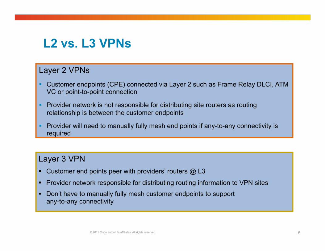
L2 vs. L3 VPNs
Layer 2 VPNs Customer endpoints (CPE) connected via Layer 2 such as Frame Relay DLCI, ATM
VC or point-to-point connection
Provider network is not responsible for distributing site routers as routing relationship is between the customer endpoints
Provider will need to manually fully mesh end points if any-to-any connectivity is required
Layer 3 VPN Customer end points peer with providers’ routers @ L3
Provider network responsible for distributing routing information to VPN sites
Don’t have to manually fully mesh customer endpoints to support any-to-any connectivity
Layer 3 VPNs
© 2011 Cisco and/or its affiliates. All rights reserved. 7
VPN A
VPN B
VPN C VPN A VPN B VPN C
VPN A
VPN B
VPN C VPN A
VPN C VPN B
Hosting
Multicast
VoIP Intranet
Extranet
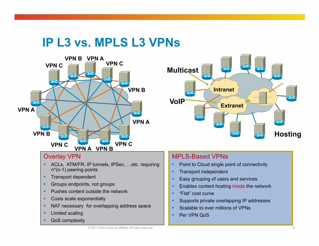
IP L3 vs. MPLS L3 VPNs
Overlay VPN ACLs, ATM/FR, IP tunnels, IPSec, …etc. requiring
n*(n-1) peering points Transport dependent Groups endpoints, not groups Pushes content outside the network Costs scale exponentially NAT necessary for overlapping address space Limited scaling QoS complexity
MPLS-Based VPNs Point to Cloud single point of connectivity Transport independent Easy grouping of users and services Enables content hosting inside the network “Flat” cost curve Supports private overlapping IP addresses Scalable to over millions of VPNs Per VPN QoS
© 2011 Cisco and/or its affiliates. All rights reserved. 8
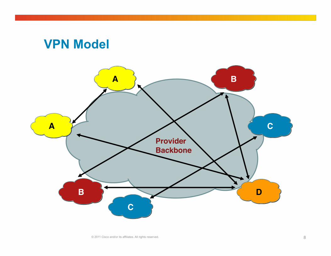
VPN Model
A! B!
C!D!B!
A! C!Provider !Backbone!

© 2011 Cisco and/or its affiliates. All rights reserved. 9
MPLS VPN Architecture
Layer 3 MPLS Backbone!
Provider (P) LSRs!
Provider Edge (PE) Label Switch Router (LSRs)!
Customer Edge (CE)! Customer Edge (CE)!
VRF interface!VRF interface!
© 2011 Cisco and/or its affiliates. All rights reserved. 10
MPLS VPN Building Blocks
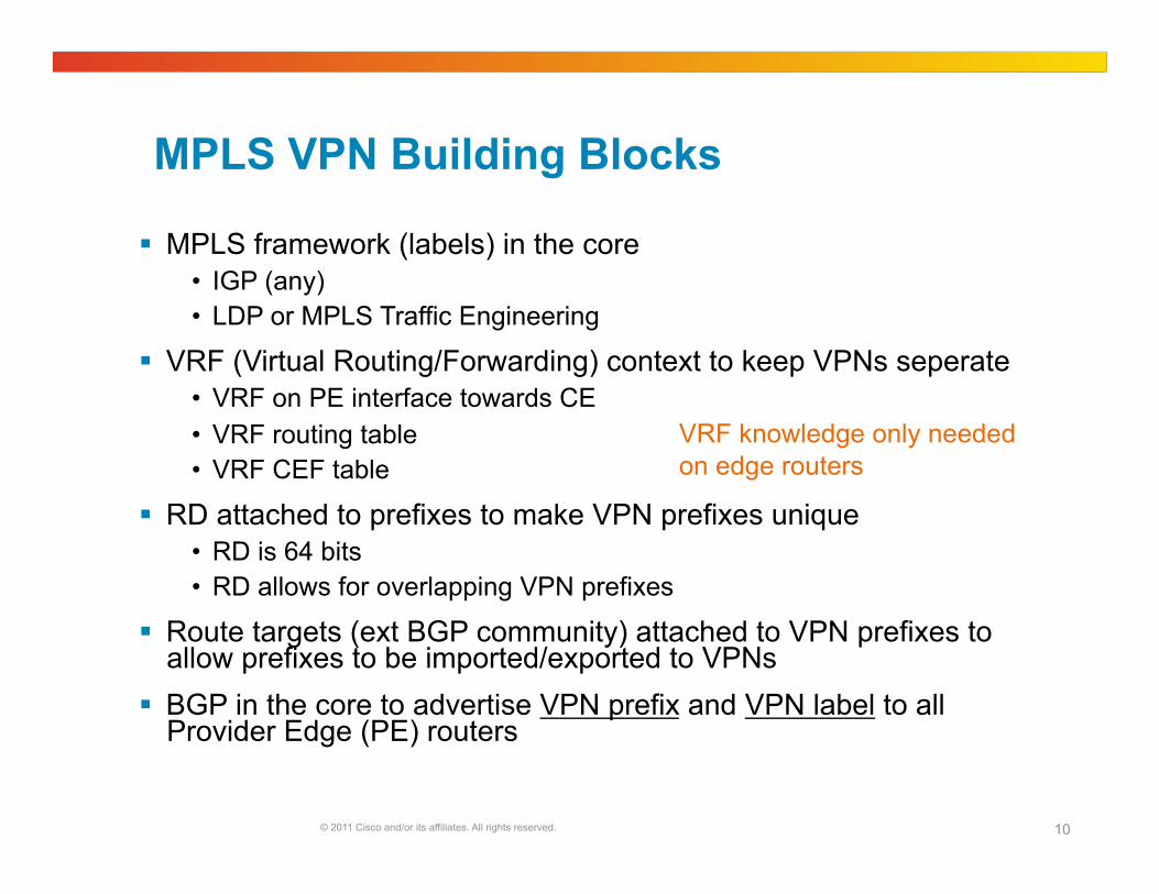
MPLS framework (labels) in the core • IGP (any) • LDP or MPLS Traffic Engineering
VRF (Virtual Routing/Forwarding) context to keep VPNs seperate • VRF on PE interface towards CE • VRF routing table • VRF CEF table
RD attached to prefixes to make VPN prefixes unique • RD is 64 bits • RD allows for overlapping VPN prefixes
Route targets (ext BGP community) attached to VPN prefixes to allow prefixes to be imported/exported to VPNs
BGP in the core to advertise VPN prefix and VPN label to all Provider Edge (PE) routers
VRF knowledge only needed on edge routers
© 2011 Cisco and/or its affiliates. All rights reserved. 11
VRF
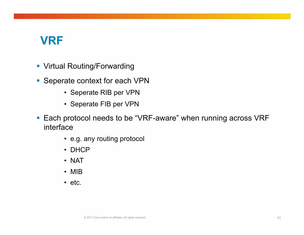
Virtual Routing/Forwarding
Seperate context for each VPN • Seperate RIB per VPN
• Seperate FIB per VPN
Each protocol needs to be “VRF-aware” when running across VRF interface
• e.g. any routing protocol • DHCP • NAT • MIB • etc.
© 2011 Cisco and/or its affiliates. All rights reserved. 12
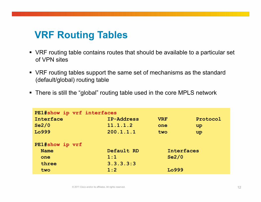
VRF Routing Tables VRF routing table contains routes that should be available to a particular set
of VPN sites
VRF routing tables support the same set of mechanisms as the standard (default/global) routing table
There is still the “global” routing table used in the core MPLS network
PE1#show ip vrf interfaces Interface IP-Address VRF Protocol Se2/0 11.1.1.2 one up Lo999 200.1.1.1 two up
PE1#show ip vrf Name Default RD Interfaces one 1:1 Se2/0 three 3.3.3.3:3 two 1:2 Lo999
© 2011 Cisco and/or its affiliates. All rights reserved. 13
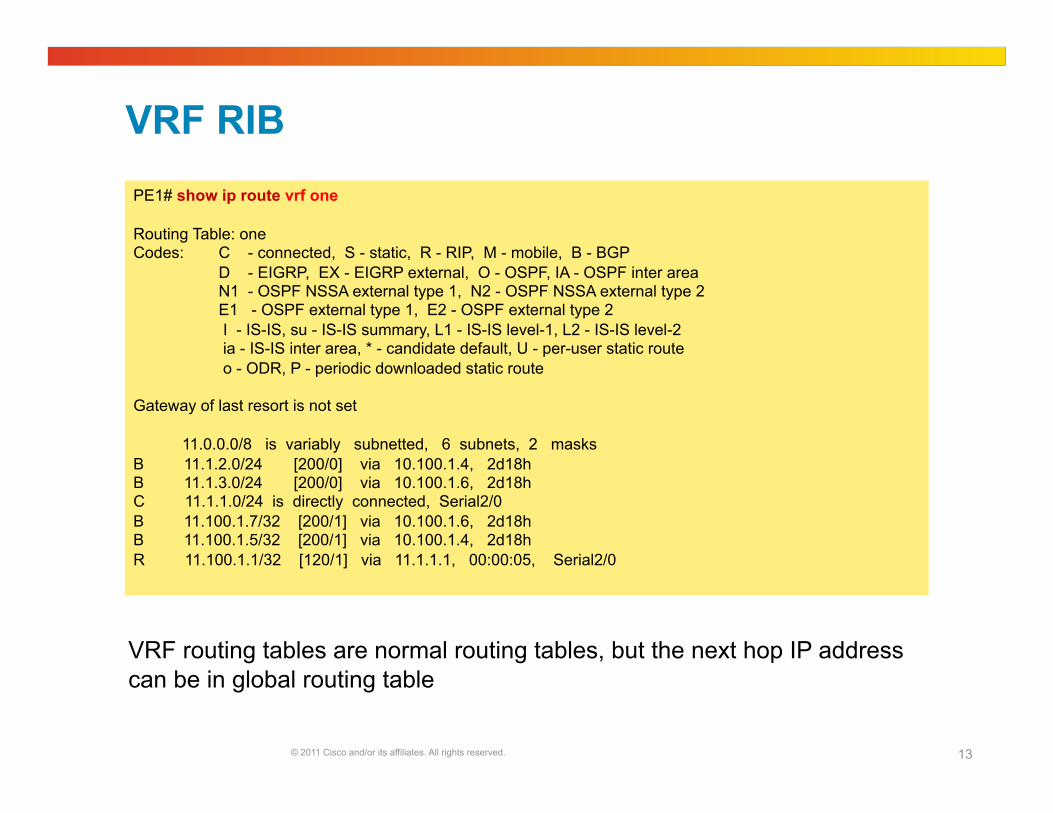
VRF RIB PE1# show ip route vrf one
Routing Table: one Codes: C - connected, S - static, R - RIP, M - mobile, B - BGP D - EIGRP, EX - EIGRP external, O - OSPF, IA - OSPF inter area N1 - OSPF NSSA external type 1, N2 - OSPF NSSA external type 2 E1 - OSPF external type 1, E2 - OSPF external type 2 I - IS-IS, su - IS-IS summary, L1 - IS-IS level-1, L2 - IS-IS level-2 ia - IS-IS inter area, * - candidate default, U - per-user static route o - ODR, P - periodic downloaded static route
Gateway of last resort is not set
11.0.0.0/8 is variably subnetted, 6 subnets, 2 masks B 11.1.2.0/24 [200/0] via 10.100.1.4, 2d18h B 11.1.3.0/24 [200/0] via 10.100.1.6, 2d18h C 11.1.1.0/24 is directly connected, Serial2/0 B 11.100.1.7/32 [200/1] via 10.100.1.6, 2d18h B 11.100.1.5/32 [200/1] via 10.100.1.4, 2d18h R 11.100.1.1/32 [120/1] via 11.1.1.1, 00:00:05, Serial2/0
VRF routing tables are normal routing tables, but the next hop IP address can be in global routing table
© 2011 Cisco and/or its affiliates. All rights reserved. 14
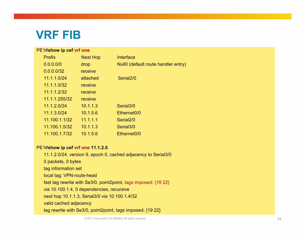
VRF FIB PE1#show ip cef vrf one
Prefix Next Hop Interface 0.0.0.0/0 drop Null0 (default route handler entry) 0.0.0.0/32 receive 11.1.1.0/24 attached Serial2/0 11.1.1.0/32 receive 11.1.1.2/32 receive 11.1.1.255/32 receive 11.1.2.0/24 10.1.1.3 Serial3/0 11.1.3.0/24 10.1.5.6 Ethernet0/0 11.100.1.1/32 11.1.1.1 Serial2/0 11.100.1.5/32 10.1.1.3 Serial3/0 11.100.1.7/32 10.1.5.6 Ethernet0/0
PE1#show ip cef vrf one 11.1.2.0 11.1.2.0/24, version 9, epoch 0, cached adjacency to Serial3/0 0 packets, 0 bytes
tag information set local tag: VPN-route-head fast tag rewrite with Se3/0, point2point, tags imposed: {19 22} via 10.100.1.4, 0 dependencies, recursive next hop 10.1.1.3, Serial3/0 via 10.100.1.4/32 valid cached adjacency tag rewrite with Se3/0, point2point, tags imposed: {19 22}
© 2011 Cisco and/or its affiliates. All rights reserved. 15
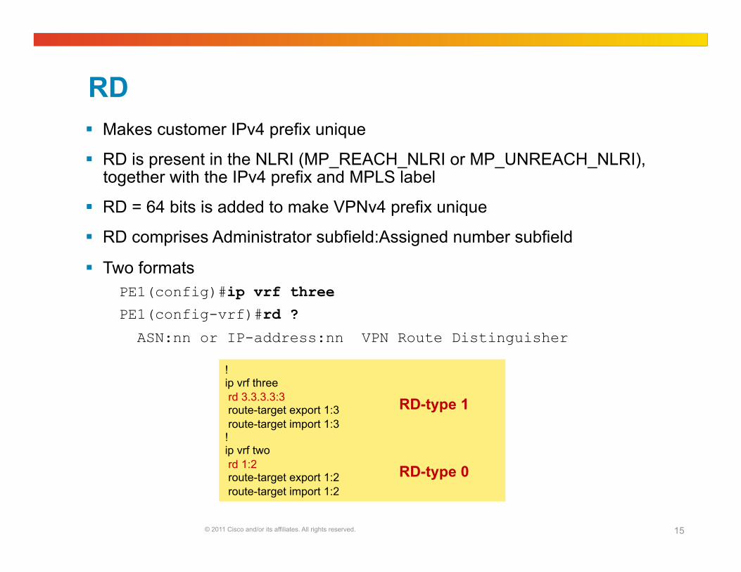
RD Makes customer IPv4 prefix unique
RD is present in the NLRI (MP_REACH_NLRI or MP_UNREACH_NLRI), together with the IPv4 prefix and MPLS label
RD = 64 bits is added to make VPNv4 prefix unique
RD comprises Administrator subfield:Assigned number subfield
Two formats PE1(config)#ip vrf three
PE1(config-vrf)#rd ?
ASN:nn or IP-address:nn VPN Route Distinguisher
! ip vrf three rd 3.3.3.3:3 route-target export 1:3 route-target import 1:3 ! ip vrf two rd 1:2 route-target export 1:2 route-target import 1:2
RD-type 0
RD-type 1
© 2011 Cisco and/or its affiliates. All rights reserved. 16
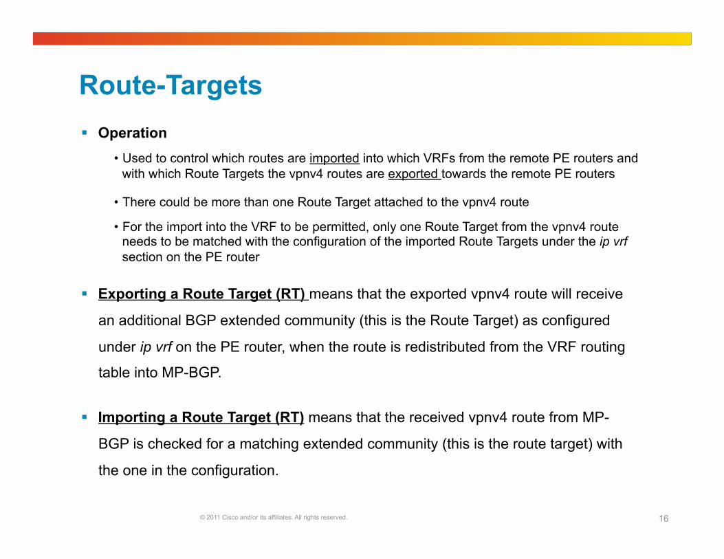
Route-Targets Operation
• Used to control which routes are imported into which VRFs from the remote PE routers and with which Route Targets the vpnv4 routes are exported towards the remote PE routers
• There could be more than one Route Target attached to the vpnv4 route
• For the import into the VRF to be permitted, only one Route Target from the vpnv4 route needs to be matched with the configuration of the imported Route Targets under the ip vrf section on the PE router
Exporting a Route Target (RT) means that the exported vpnv4 route will receive
an additional BGP extended community (this is the Route Target) as configured
under ip vrf on the PE router, when the route is redistributed from the VRF routing
table into MP-BGP.
Importing a Route Target (RT) means that the received vpnv4 route from MP-
BGP is checked for a matching extended community (this is the route target) with
the one in the configuration.
© 2011 Cisco and/or its affiliates. All rights reserved. 17
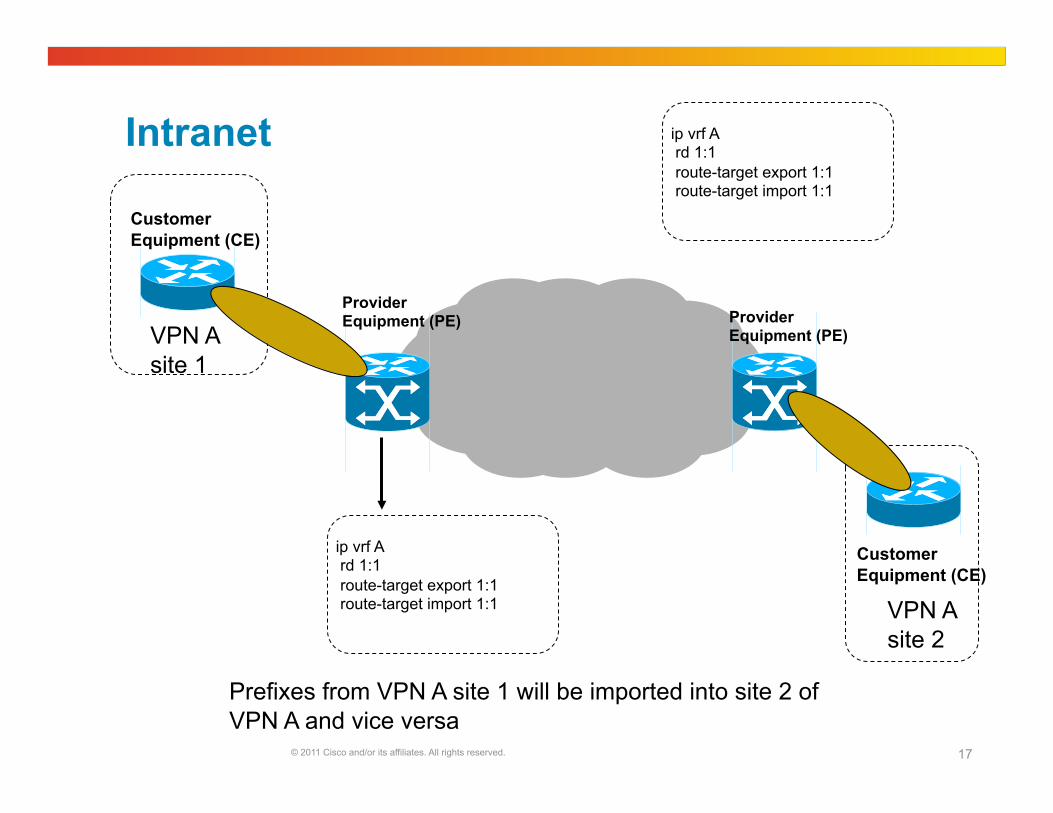
Intranet
Customer Equipment (CE)
Customer Equipment (CE)
VPN A site 1
Provider Equipment (PE) Provider
Equipment (PE)
VPN A site 2
ip vrf A rd 1:1 route-target export 1:1 route-target import 1:1
Prefixes from VPN A site 1 will be imported into site 2 of VPN A and vice versa
ip vrf A rd 1:1 route-target export 1:1 route-target import 1:1

© 2011 Cisco and/or its affiliates. All rights reserved. 18
Extranet
Customer Equipment (CE)
Customer Equipment (CE)
VPN A site 1
Provider Equipment (PE) Provider
Equipment (PE)
VPN B site 1
ip vrf A rd 1:1 route-target export 1:1 route-target import 1:1
ip vrf B rd 1:2 route-target export 1:2 route-target import 1:2
Prefixes from VPN A site 1 will be imported into site 1 of VPN B and vice versa
route-target import 1:1
route-target import 1:2
© 2011 Cisco and/or its affiliates. All rights reserved. 19
Role of BGP
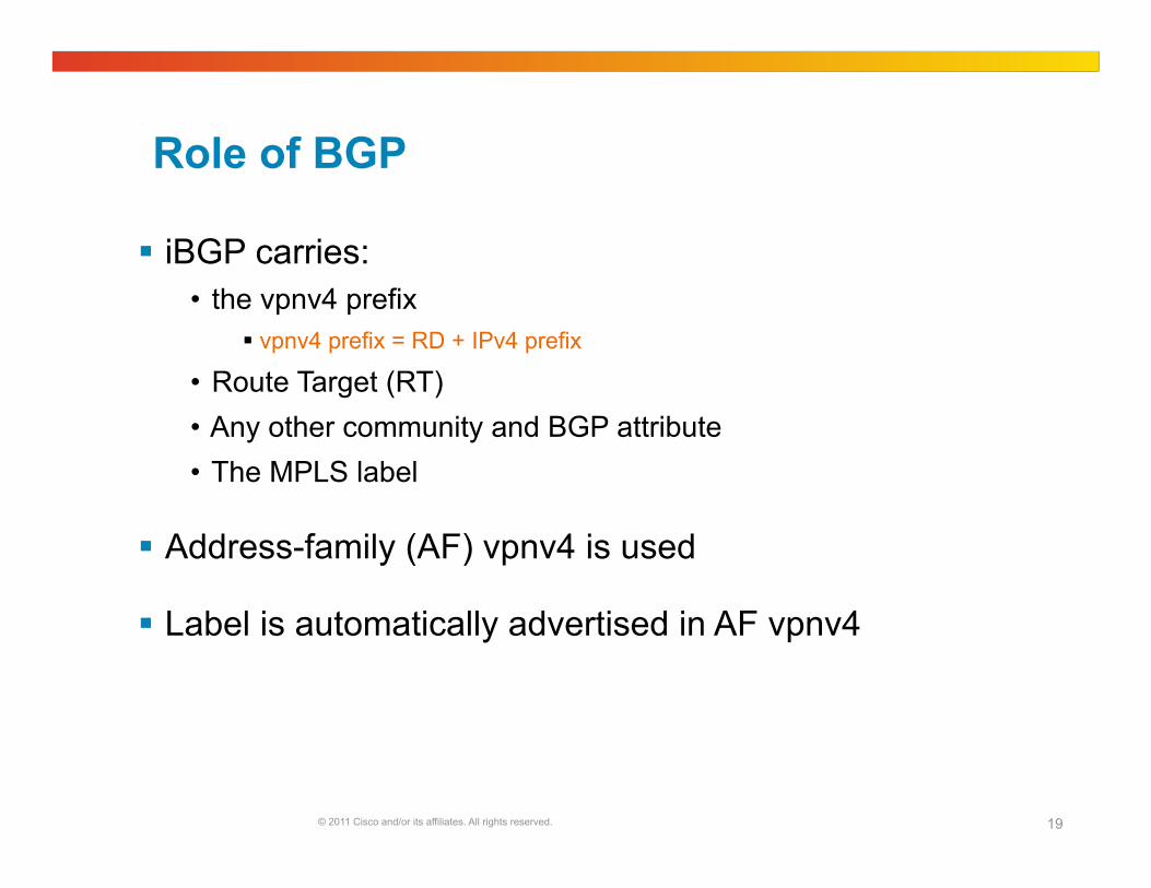
iBGP carries: • the vpnv4 prefix
vpnv4 prefix = RD + IPv4 prefix
• Route Target (RT) • Any other community and BGP attribute • The MPLS label
Address-family (AF) vpnv4 is used
Label is automatically advertised in AF vpnv4
© 2011 Cisco and/or its affiliates. All rights reserved. 20
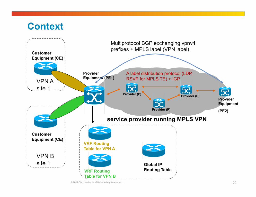
Context
Customer Equipment (CE)
Customer Equipment (CE)
VPN A site 1
VPN B site 1
service provider running MPLS VPN
Global IP Routing Table
VRF Routing Table for VPN A
VRF Routing Table for VPN B
Provider Equipment (PE1)
A label distribution protocol (LDP, RSVP for MPLS TE) + IGP
Multiprotocol BGP exchanging vpnv4 prefixes + MPLS label (VPN label)
Provider Equipment
(PE2) Provider (P)
Provider (P) Provider (P)
© 2011 Cisco and/or its affiliates. All rights reserved. 21
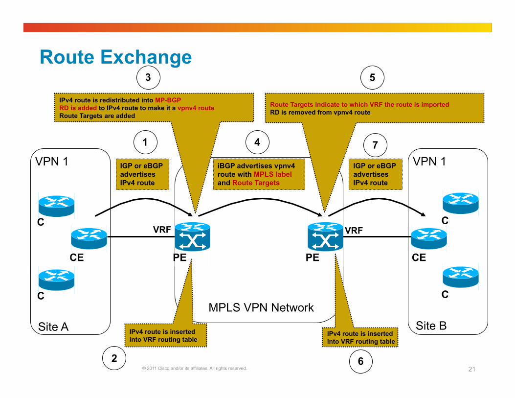
Route Exchange
PE
MPLS VPN Network
PE CE CE
C
C
C
C
VPN 1 VPN 1
Site B Site A
VRF VRF
IGP or eBGP advertises IPv4 route
1
IPv4 route is redistributed into MP-BGP RD is added to IPv4 route to make it a vpnv4 route Route Targets are added
3
Route Targets indicate to which VRF the route is imported RD is removed from vpnv4 route
5
IGP or eBGP advertises IPv4 route
7
iBGP advertises vpnv4 route with MPLS label and Route Targets
4
IPv4 route is inserted into VRF routing table
2
IPv4 route is inserted into VRF routing table
6
© 2011 Cisco and/or its affiliates. All rights reserved. 22
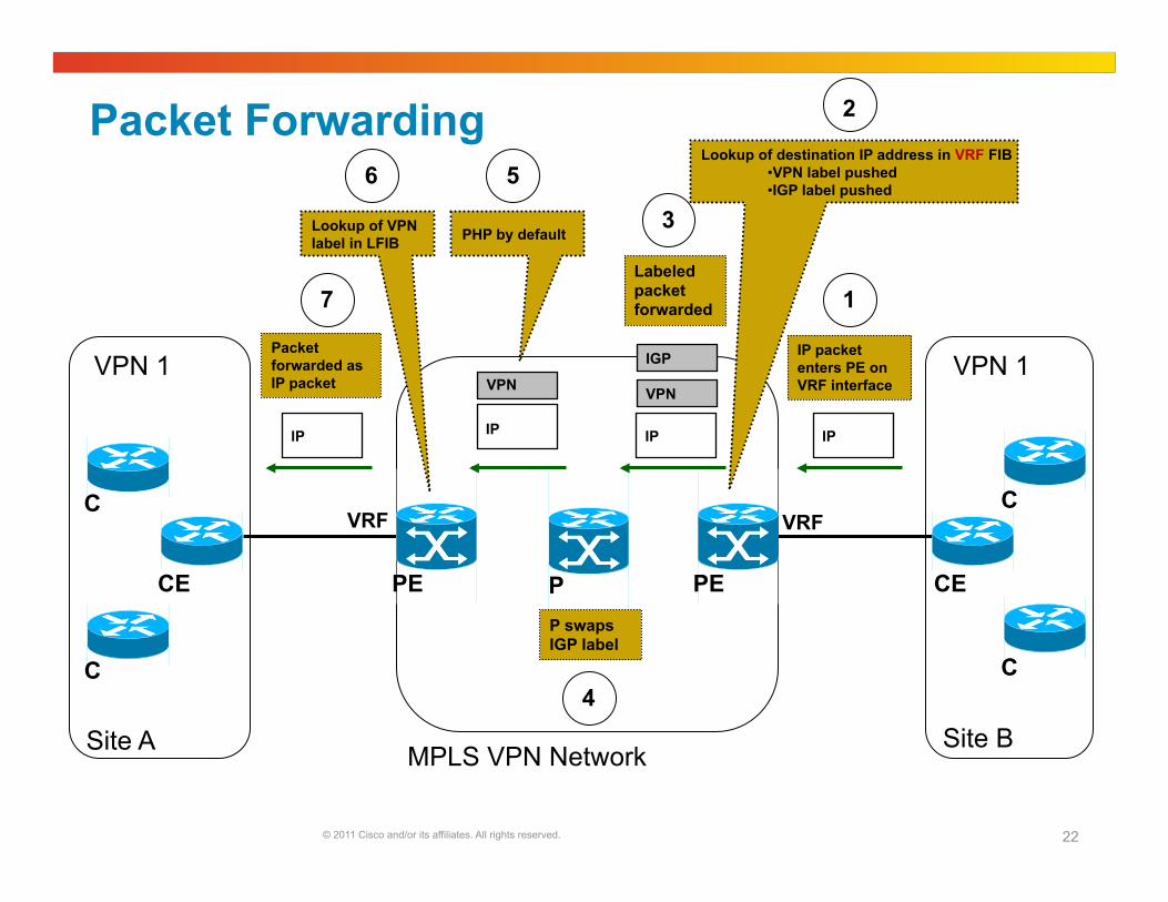
Packet Forwarding
PE
MPLS VPN Network
PE CE CE
C
C
C
C
VPN 1 VPN 1
Site B Site A
VRF VRF
IP
IP packet enters PE on VRF interface
1
Lookup of destination IP address in VRF FIB • VPN label pushed • IGP label pushed
2
IP
VPN
IGP
Labeled packet forwarded
3
P swaps IGP label
4
P
IP
Packet forwarded as IP packet
7
IP
VPN
PHP by default
5
Lookup of VPN label in LFIB
6
© 2011 Cisco and/or its affiliates. All rights reserved. 23
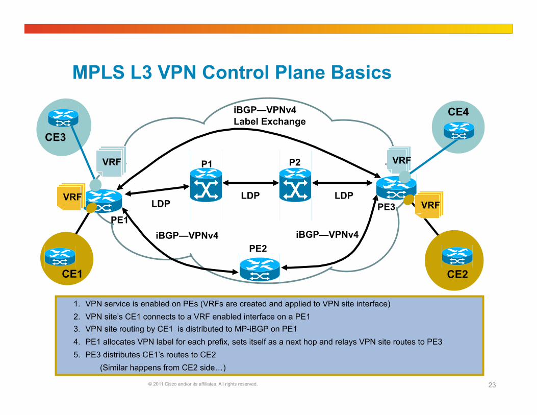
MPLS L3 VPN Control Plane Basics
VRF VRF
LDP LDP LDP
PE1 PE3
PE2
CE1
CE4
CE3
1. VPN service is enabled on PEs (VRFs are created and applied to VPN site interface) 2. VPN site’s CE1 connects to a VRF enabled interface on a PE1 3. VPN site routing by CE1 is distributed to MP-iBGP on PE1 4. PE1 allocates VPN label for each prefix, sets itself as a next hop and relays VPN site routes to PE3 5. PE3 distributes CE1’s routes to CE2
(Similar happens from CE2 side…)
CE2
iBGP—VPNv4 iBGP—VPNv4
iBGP—VPNv4 Label Exchange
P1 P2
VRF VRF
© 2011 Cisco and/or its affiliates. All rights reserved. 24
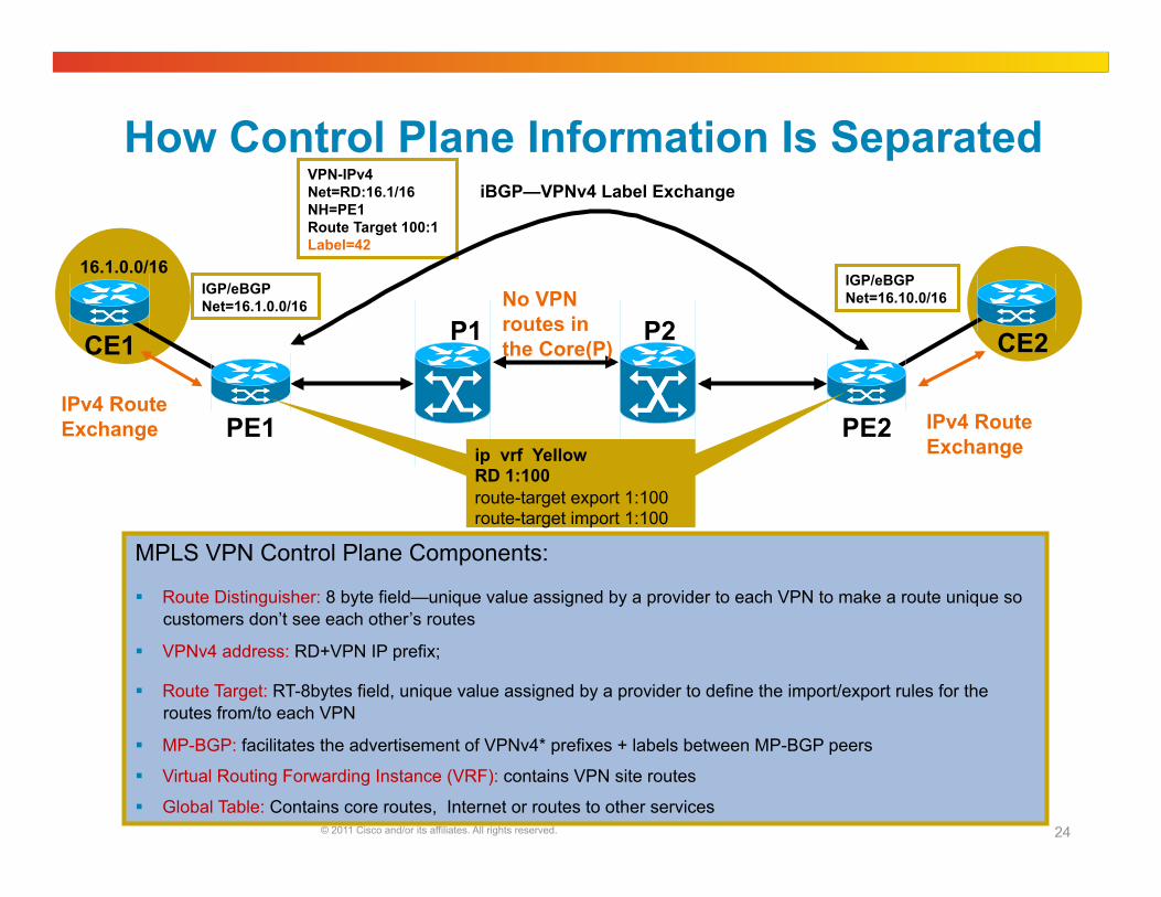
How Control Plane Information Is Separated
MPLS VPN Control Plane Components:
Route Distinguisher: 8 byte field—unique value assigned by a provider to each VPN to make a route unique so customers don’t see each other’s routes
VPNv4 address: RD+VPN IP prefix;
Route Target: RT-8bytes field, unique value assigned by a provider to define the import/export rules for the routes from/to each VPN
MP-BGP: facilitates the advertisement of VPNv4* prefixes + labels between MP-BGP peers
Virtual Routing Forwarding Instance (VRF): contains VPN site routes
Global Table: Contains core routes, Internet or routes to other services
PE1
P1 P2
PE2
CE2 CE1
16.1.0.0/16
IPv4 Route Exchange
IGP/eBGP Net=16.1.0.0/16
IGP/eBGP Net=16.10.0/16 No VPN
routes in the Core(P)
VPN-IPv4 Net=RD:16.1/16 NH=PE1 Route Target 100:1 Label=42
ip vrf Yellow RD 1:100 route-target export 1:100 route-target import 1:100
iBGP—VPNv4 Label Exchange
IPv4 Route Exchange
© 2011 Cisco and/or its affiliates. All rights reserved. 25
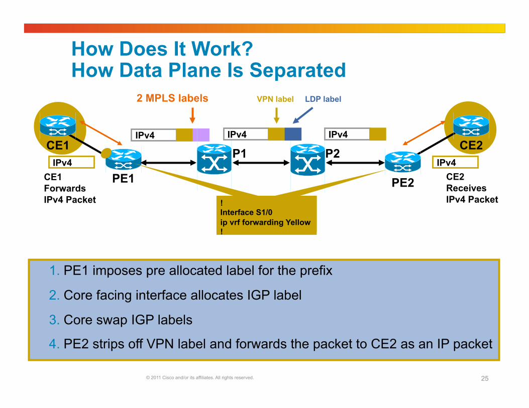
How Does It Work? How Data Plane Is Separated
1. PE1 imposes pre allocated label for the prefix
2. Core facing interface allocates IGP label
3. Core swap IGP labels
4. PE2 strips off VPN label and forwards the packet to CE2 as an IP packet
CE1 Forwards IPv4 Packet
IPv4
IPv4
PE1 PE2
CE2 CE1 IPv4 IPv4
IPv4 CE2 Receives IPv4 Packet !
Interface S1/0 ip vrf forwarding Yellow !
P1 P2
2 MPLS labels VPN label LDP label

© 2011 Cisco and/or its affiliates. All rights reserved. 26
Config on PE Router ip vrf one rd 1:1 route-target export 1:1 route-target import 1:1 ! interface FastEthernet2/1 ip vrf forwarding one ip address 99.1.1.2 255.255.255.0 ! router ospf 100 vrf one log-adjacency-changes redistribute bgp 1 metric 10 subnets network 99.1.1.0 0.0.0.255 area 0 ! router bgp 1 bgp log-neighbor-changes neighbor 11.100.100.4 remote-as 1 neighbor 11.100.100.4 update-source Loopback0 ! address-family ipv4 no synchronization neighbor 11.100.100.4 activate neighbor 11.100.100.4 send-community both exit-address-family ! address-family vpnv4 neighbor 11.100.100.4 activate neighbor 11.100.100.4 send-community both exit-address-family ! address-family ipv4 vrf one redistribute connected redistribute ospf 100 vrf one exit-address-family
Definition of VRF
Assigning CE-facing interface to VRF
Confiuring BGP vpnv4 peering
(to all other PEs or RRs)
Configuring VRF BGP (redistribution)
PE-CE routing protocol
© 2011 Cisco and/or its affiliates. All rights reserved. 27
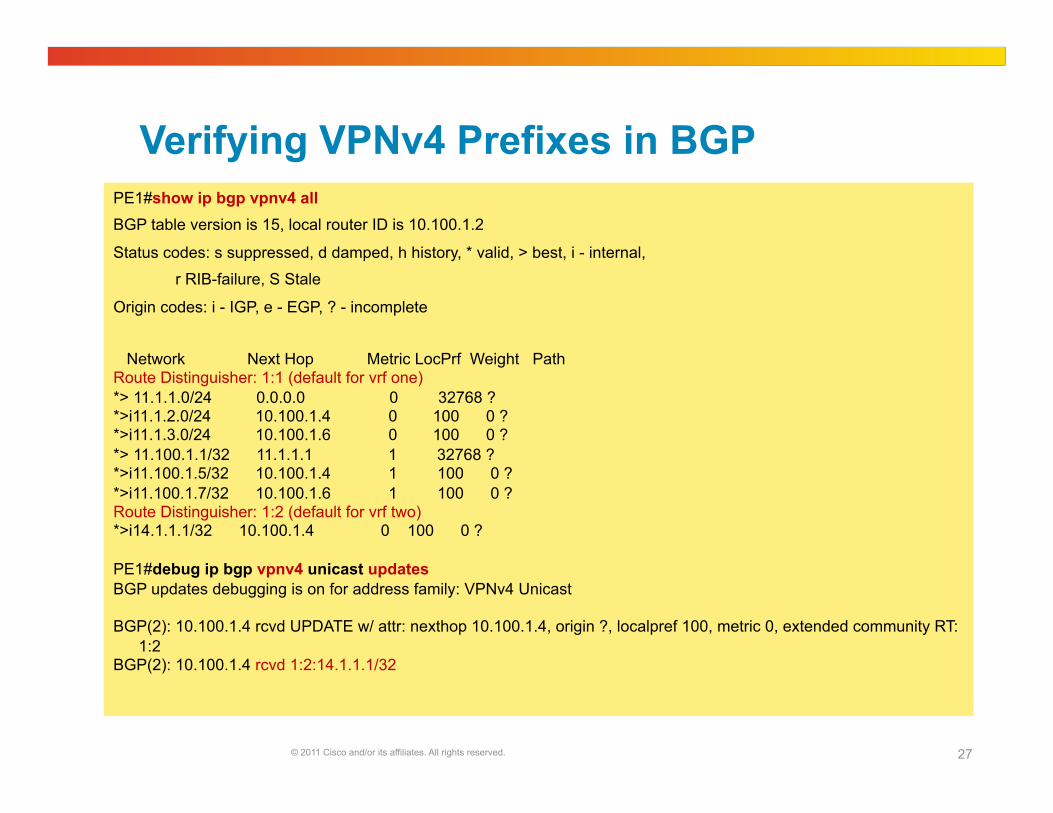
Verifying VPNv4 Prefixes in BGP PE1#show ip bgp vpnv4 all BGP table version is 15, local router ID is 10.100.1.2
Status codes: s suppressed, d damped, h history, * valid, > best, i - internal,
r RIB-failure, S Stale
Origin codes: i - IGP, e - EGP, ? - incomplete
Network Next Hop Metric LocPrf Weight Path Route Distinguisher: 1:1 (default for vrf one) *> 11.1.1.0/24 0.0.0.0 0 32768 ? *>i11.1.2.0/24 10.100.1.4 0 100 0 ? *>i11.1.3.0/24 10.100.1.6 0 100 0 ? *> 11.100.1.1/32 11.1.1.1 1 32768 ? *>i11.100.1.5/32 10.100.1.4 1 100 0 ? *>i11.100.1.7/32 10.100.1.6 1 100 0 ? Route Distinguisher: 1:2 (default for vrf two) *>i14.1.1.1/32 10.100.1.4 0 100 0 ?
PE1#debug ip bgp vpnv4 unicast updates BGP updates debugging is on for address family: VPNv4 Unicast
BGP(2): 10.100.1.4 rcvd UPDATE w/ attr: nexthop 10.100.1.4, origin ?, localpref 100, metric 0, extended community RT:1:2
BGP(2): 10.100.1.4 rcvd 1:2:14.1.1.1/32
© 2011 Cisco and/or its affiliates. All rights reserved. 28
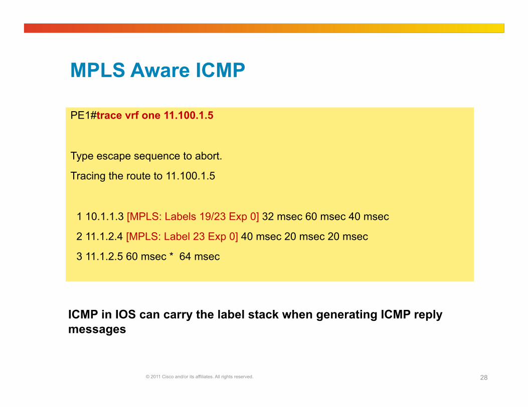
MPLS Aware ICMP
PE1#trace vrf one 11.100.1.5
Type escape sequence to abort.
Tracing the route to 11.100.1.5
1 10.1.1.3 [MPLS: Labels 19/23 Exp 0] 32 msec 60 msec 40 msec
2 11.1.2.4 [MPLS: Label 23 Exp 0] 40 msec 20 msec 20 msec
3 11.1.2.5 60 msec * 64 msec
ICMP in IOS can carry the label stack when generating ICMP reply messages
© 2011 Cisco and/or its affiliates. All rights reserved. 29
PE-CE Routing Protocols
Connected
Static
RIPv2
OSPF
EIGRP
eBGP
© 2011 Cisco and/or its affiliates. All rights reserved. 30
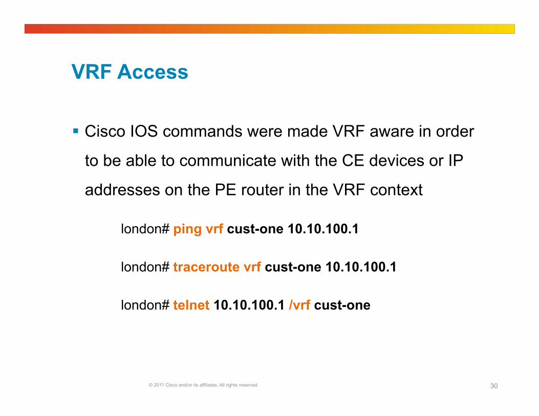
VRF Access
Cisco IOS commands were made VRF aware in order
to be able to communicate with the CE devices or IP
addresses on the PE router in the VRF context
london# ping vrf cust-one 10.10.100.1
london# traceroute vrf cust-one 10.10.100.1
london# telnet 10.10.100.1 /vrf cust-one
© 2011 Cisco and/or its affiliates. All rights reserved. 31
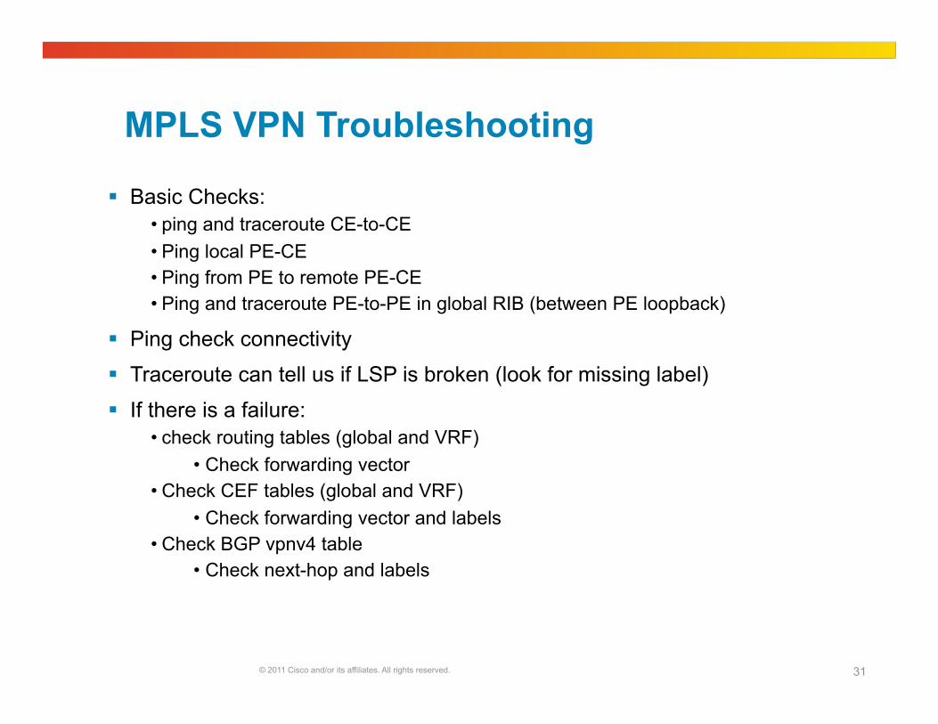
MPLS VPN Troubleshooting
Basic Checks: • ping and traceroute CE-to-CE • Ping local PE-CE • Ping from PE to remote PE-CE • Ping and traceroute PE-to-PE in global RIB (between PE loopback)
Ping check connectivity
Traceroute can tell us if LSP is broken (look for missing label)
If there is a failure: • check routing tables (global and VRF)
• Check forwarding vector • Check CEF tables (global and VRF)
• Check forwarding vector and labels • Check BGP vpnv4 table
• Check next-hop and labels
© 2011 Cisco and/or its affiliates. All rights reserved. 32
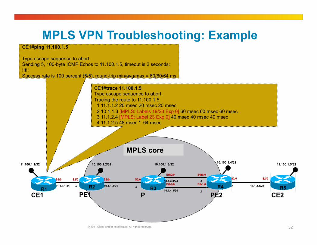
MPLS VPN Troubleshooting: Example
10.100.1.3/32
R3 R2 R1
10.1.0.0/16
11.100.1.1/32 10.100.1.2/32
R1 R2 R3 R5
10.100.1.4/32
R4 R6
11.100.1.5/32
R5 11.1.1.1/24 .2 11.1.2.5/24 .4 10.1.1.2/24 .3
.4
.4
10.1.3.3/24
10.1.4.3/24
S2/0 S2/0 S3/0 S3/0 S2/0 S2/0 Eth0/0 Eth0/0
Eth1/0 Eth1/0
MPLS core
CE1#ping 11.100.1.5
Type escape sequence to abort. Sending 5, 100-byte ICMP Echos to 11.100.1.5, timeout is 2 seconds: !!!!! Success rate is 100 percent (5/5), round-trip min/avg/max = 60/60/64 ms
CE1#trace 11.100.1.5 Type escape sequence to abort. Tracing the route to 11.100.1.5 1 11.1.1.2 20 msec 20 msec 20 msec 2 10.1.1.3 [MPLS: Labels 19/23 Exp 0] 60 msec 60 msec 60 msec 3 11.1.2.4 [MPLS: Label 23 Exp 0] 40 msec 40 msec 40 msec 4 11.1.2.5 48 msec * 64 msec
PE1 PE2 P CE1 CE2

© 2011 Cisco and/or its affiliates. All rights reserved. 33
MPLS core
MPLS VPN Troubleshooting: Example
10.100.1.3/32
R3 R2 R1
10.1.0.0/16
11.100.1.1/32 10.100.1.2/32
R1 R2 R3 R5
10.100.1.4/32
R4 R6
11.100.1.5/32
R5 11.1.1.1/24 .2 11.1.2.5/24 .4 10.1.1.2/24 .3
.4
.4
10.1.3.3/24
10.1.4.3/24
S2/0 S2/0 S3/0 S3/0 S2/0 S2/0 Eth0/0 Eth0/0
Eth1/0 Eth1/0
PE1#ping vrf one 11.100.1.5
Type escape sequence to abort. Sending 5, 100-byte ICMP Echos to 11.100.1.5, timeout is 2 seconds: !!!!! Success rate is 100 percent (5/5), round-trip min/avg/max = 40/52/72 ms
PE1#trace vrf one 11.100.1.5
Type escape sequence to abort. Tracing the route to 11.100.1.5
1 10.1.1.3 [MPLS: Labels 19/23 Exp 0] 32 msec 60 msec 40 msec 2 11.1.2.4 [MPLS: Label 23 Exp 0] 40 msec 20 msec 20 msec 3 11.1.2.5 60 msec * 64 msec
PE1 PE2 P CE1 CE2

© 2011 Cisco and/or its affiliates. All rights reserved. 34
MPLS core
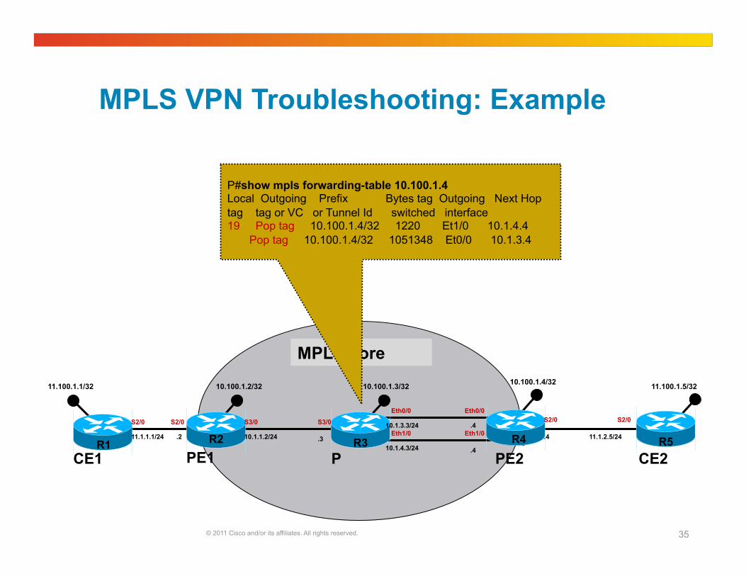
MPLS VPN Troubleshooting: Example
10.100.1.3/32
R3 R2 R1
10.1.0.0/16
11.100.1.1/32 10.100.1.2/32
R1 R2 R3 R5
10.100.1.4/32
R4 R6
11.100.1.5/32
R5 11.1.1.1/24 .2 11.1.2.5/24 .4 10.1.1.2/24 .3
.4
.4
10.1.3.3/24
10.1.4.3/24
S2/0 S2/0 S3/0 S3/0 S2/0 S2/0 Eth0/0 Eth0/0
Eth1/0 Eth1/0
PE1#show ip cef vrf one 11.100.1.5 11.100.1.5/32, version 10, epoch 0, cached adjacency to Serial3/0 0 packets, 0 bytes tag information set local tag: VPN-route-head fast tag rewrite with Se3/0, point2point, tags imposed: {19 23} via 10.100.1.4, 0 dependencies, recursive next hop 10.1.1.3, Serial3/0 via 10.100.1.4/32 valid cached adjacency tag rewrite with Se3/0, point2point, tags imposed: {19 23}
PE1#show ip cef 10.100.1.4 10.100.1.4/32, version 20, epoch 0, cached adjacency to Serial3/0 0 packets, 0 bytes tag information set, shared local tag: 23 fast tag rewrite with Se3/0, point2point, tags imposed: {19} via 10.1.1.3, Serial3/0, 2 dependencies next hop 10.1.1.3, Serial3/0 valid cached adjacency tag rewrite with Se3/0, point2point, tags imposed: {19}
PE1#show ip bgp vpnv4 vrf one 11.100.1.5 BGP routing table entry for 1:1:11.100.1.5/32, version 12 Paths: (1 available, best #1, table one) Not advertised to any peer Local 10.100.1.4 (metric 75) from 10.100.1.4 (10.100.1.4) Origin incomplete, metric 0, localpref 100, valid, internal, best Extended Community: RT:1:1 mpls labels in/out nolabel/23
BGP next-hop
PE1 PE2 P CE1 CE2
© 2011 Cisco and/or its affiliates. All rights reserved. 35
MPLS core
MPLS VPN Troubleshooting: Example
10.100.1.3/32
R3 R2 R1
10.1.0.0/16
11.100.1.1/32 10.100.1.2/32
R1 R2 R3 R5
10.100.1.4/32
R4 R6
11.100.1.5/32
R5 11.1.1.1/24 .2 11.1.2.5/24 .4 10.1.1.2/24 .3
.4
.4
10.1.3.3/24
10.1.4.3/24
S2/0 S2/0 S3/0 S3/0 S2/0 S2/0 Eth0/0 Eth0/0
Eth1/0 Eth1/0
P#show mpls forwarding-table 10.100.1.4 Local Outgoing Prefix Bytes tag Outgoing Next Hop tag tag or VC or Tunnel Id switched interface 19 Pop tag 10.100.1.4/32 1220 Et1/0 10.1.4.4 Pop tag 10.100.1.4/32 1051348 Et0/0 10.1.3.4
PE1 PE2 P CE1 CE2

© 2011 Cisco and/or its affiliates. All rights reserved. 36
MPLS VPN Troubleshooting: Example
10.100.1.3/32
R3 R2 R1
10.1.0.0/16
11.100.1.1/32 10.100.1.2/32
R1 R2 R3 R5
10.100.1.4/32
R4 R6
11.100.1.5/32
R5 11.1.1.1/24 .2 11.1.2.5/24 .4 10.1.1.2/24 .3
.4
.4
10.1.3.3/24
10.1.4.3/24
S2/0 S2/0 S3/0 S3/0 S2/0 S2/0 Eth0/0 Eth0/0
Eth1/0 Eth1/0
MPLS core
PE2#show mpls forwarding-table labels 23 Local Outgoing Prefix Bytes Label Outgoing Next Hop Label Label or VC or Tunnel Id Switched interface 23 No Label 11.100.1.5/32[V] 0 Se2/0 point2point
PE1 PE2 P CE1 CE2

© 2011 Cisco and/or its affiliates. All rights reserved. 37
MPLS VPN Troubleshooting: Example Debugging Control plane
10.100.1.3/32
R3 R2 R1
10.1.0.0/16
11.100.1.1/32 10.100.1.2/32
R1 R2 R3 R5
10.100.1.4/32
R4 R6
11.100.1.5/32
R5 11.1.1.1/24 .2 11.1.2.5/24 .4 10.1.1.2/24 .3
.4
.4
10.1.3.3/24
10.1.4.3/24
S2/0 S2/0 S3/0 S3/0 S2/0 S2/0 Eth0/0 Eth0/0
Eth1/0 Eth1/0
MPLS core
PE1#debug ip bgp vpnv4 unicast updates BGP updates debugging is on for address family: VPNv4 Unicast PE1#show debug IP routing: BGP updates debugging is on for address family: VPNv4 Unicast
PE2#debug ip bgp vpnv4 unicast updates BGP updates debugging is on for address family: VPNv4 Unicast
PE2#show debug IP routing: BGP updates debugging is on for address family: VPNv4 Unicast
PE1#debug ip routing vrf one IP routing debugging is on for VRF one PE1#show debug IP routing: IP routing debugging is on for VRF one
PE2#debug ip routing vrf one IP routing debugging is on for VRF one PE2#show debug IP routing: IP routing debugging is on for VRF one
CE1#debug ip routing IP routing debugging is on CE1#show debug IP routing: IP routing debugging is on
CE2#debug ip routing IP routing debugging is on CE2#show debug IP routing: IP routing debugging is on
PE1 PE2 P CE1 CE2
Summary
© 2011 Cisco and/or its affiliates. All rights reserved. 39
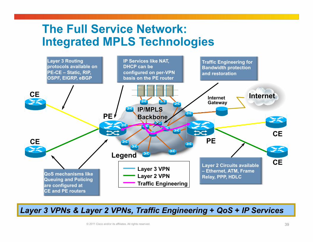
The Full Service Network: Integrated MPLS Technologies
Layer 3 VPNs & Layer 2 VPNs, Traffic Engineering + QoS + IP Services
CE
PE
PE CE
CE QoS mechanisms like Queuing and Policing are configured at CE and PE routers
Layer 3 Routing protocols available on PE-CE – Static, RIP, OSPF, EIGRP, eBGP
CE
Layer 2 Circuits available – Ethernet, ATM, Frame Relay, PPP, HDLC
IP Services like NAT, DHCP can be configured on per-VPN basis on the PE router
Layer 3 VPN Layer 2 VPN Traffic Engineering
Legend
Traffic Engineering for Bandwidth protection and restoration
Internet Gateway
Internet
If you have additional questions, you can ask them to Nagendra here:
https://supportforums.cisco.com/community/netpro/ask-the-expert
He will be answering from August 17th to August 26th.
© 2011 Cisco and/or its affiliates. All rights reserved. 41
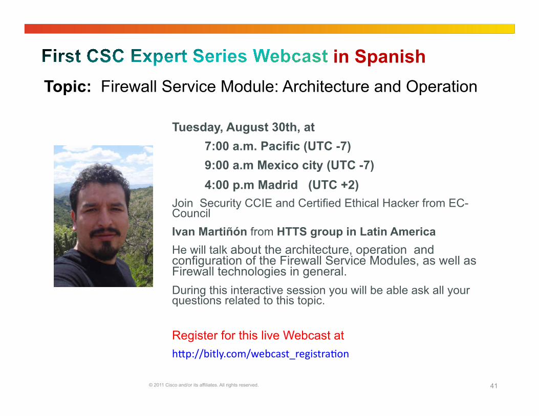
in Spanish
Tuesday, August 30th, at 7:00 a.m. Pacific (UTC -7) 9:00 a.m Mexico city (UTC -7) 4:00 p.m Madrid (UTC +2)
Join Security CCIE and Certified Ethical Hacker from EC-Council Ivan Martiñón from HTTS group in Latin America He will talk about the architecture, operation and configuration of the Firewall Service Modules, as well as Firewall technologies in general. During this interactive session you will be able ask all your questions related to this topic.
Register for this live Webcast at h"p://bitly.com/webcast_registra6on
Topic: Firewall Service Module: Architecture and Operation
© 2011 Cisco and/or its affiliates. All rights reserved. 42
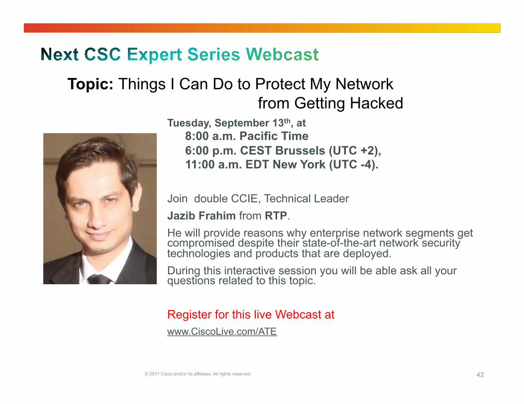
Tuesday, September 13th, at 8:00 a.m. Pacific Time 6:00 p.m. CEST Brussels (UTC +2), 11:00 a.m. EDT New York (UTC -4).
Join double CCIE, Technical Leader Jazib Frahim from RTP. He will provide reasons why enterprise network segments get compromised despite their state-of-the-art network security technologies and products that are deployed. During this interactive session you will be able ask all your questions related to this topic.
Register for this live Webcast at www.CiscoLive.com/ATE
Topic: Things I Can Do to Protect My Network from Getting Hacked
© 2011 Cisco and/or its affiliates. All rights reserved. 43
If you speak Polish, Japanese, or Spanish, we invite you to ask your questions and collaborate in your language.
• Spanish https://supportforums.cisco.com/community/spanish
• Polish https://supportforums.cisco.com/community/ etc/netpro-polska
• Japanese https://supportforums.cisco.com/community/csc-japan
We’re also running a pilot for Russian and Portuguese. You can register at the following links
• Russian: https://www.ciscofeedback.vovici.com/se.ashx?s=6A5348A712220E19
• Portuguese: https://www.ciscofeedback.vovici.com/se.ashx?s=6A5348A77EE5C0B7