Embed Size (px)
Citation preview
© 2011 Cisco and/or its affiliates. All rights reserved. Cisco PublicBRKMPL-2105 22
The Prerequisites
Must understand basic IP routing Familiar with MPLS architectures Familiar with MPLS applications Some level of MPLS network design/
deployment experience
2

© 2011 Cisco and/or its affiliates. All rights reserved. Cisco PublicBRKMPL-2105 33
Goal
Explore Inter-AS MPLS VPN use cases Discuss various architectures that facilitate support of
MPLS VPN services in Inter-AS environment Highlight some of the key differences between IOS and
IOS XR Introduce some of the key commands in IOS or IOS XR For full configuration examples please refer to
www.cisco.com
3
© 2011 Cisco and/or its affiliates. All rights reserved. Cisco PublicBRKMPL-2105 4
Agenda
Inter-AS NetworksInter-AS Connectivity ModelsInter-AS L3 VPNsInter-AS L2VPNsInter-AS Multicast VPNs
Carrier Supporting Carrier
CSC Service ModelsMPLS L3 VPNsMulticast VPNsMPLS L2 VPNs
Inter-AS RSVP-TE
© 2011 Cisco and/or its affiliates. All rights reserved. Cisco PublicBRKMPL-2105 55
Inter-AS MPLS Service Use Cases
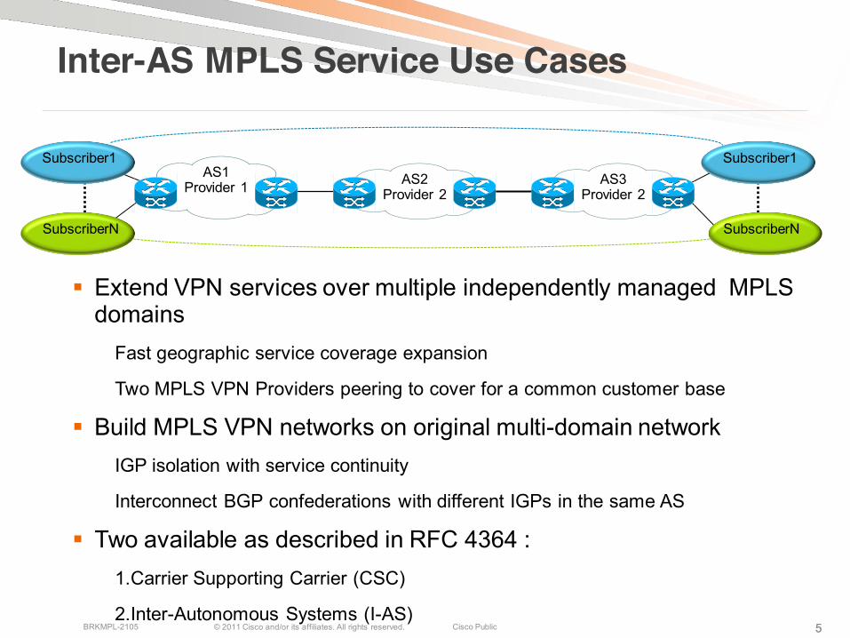
Extend VPN services over multiple independently managed MPLSdomains
Fast geographic service coverage expansion
Two MPLS VPN Providers peering to cover for a common customer base
Build MPLS VPN networks on original multi-domain networkIGP isolation with service continuity
Interconnect BGP confederations with different IGPs in the same AS
Two available as described in RFC 4364 :1.Carrier Supporting Carrier (CSC)
2.Inter-Autonomous Systems (I-AS)
AS3Provider 2
AS2Provider 2
AS1Provider 1
Subscriber1Subscriber1
SubscriberN SubscriberN
5
© 2011 Cisco and/or its affiliates. All rights reserved. Cisco PublicBRKMPL-2105 6
Carrier Supporting Carrier vs. Inter-AS
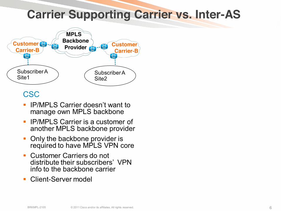
CSC IP/MPLS Carrier doesn’t want to
manage own MPLS backbone IP/MPLS Carrier is a customer of
another MPLS backbone provider Only the backbone provider is
required to have MPLS VPN core Customer Carriers do not
distribute their subscribers’ VPNinfo to the backbone carrier
Client-Server model
Inter-AS Single SP POPs not available in
all geographical areas required by their subscribers/customers
SPs provide services to the common customer base
Both SPs must support MPLSVPNs
Subscribers’ VPN information distributed to peering SPs’ network
Peer-Peer model
MPLS Backbone ProviderCustomer
Carrier-BCustomer Carrier-B
Subscriber A Site1
Subscriber A Site2
Subscriber A Site1 Subscriber A
Site2
Provider-A Provider-BASBR-A ASBR-B
6
© 2011 Cisco and/or its affiliates. All rights reserved. Cisco PublicBRKMPL-2105 7
Inter-AS L3 VPNsOverview

© 2011 Cisco and/or its affiliates. All rights reserved. Cisco PublicBRKMPL-2105 8
Extending VPN services over Inter-AS networks
VPN-R1 VPN-R2
PE22
CE2 CE1
AS #1 AS #2PE11
MP-eBGP for VPNv4(Option B)
Multihop MP-eBGPbetween RRs
(Option C)MP-eBGP+Labels
Back-to-Back VRFs(Option A)
ASBR1 ASBR2
•VPN Sites attached to different MPLS VPN Service Providers•How do you distribute and share VPN routes between ASs
© 2011 Cisco and/or its affiliates. All rights reserved. Cisco PublicBRKMPL-2105 99
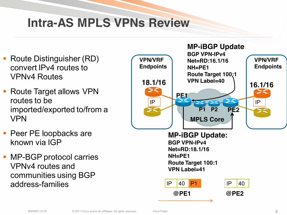
Intra-AS MPLS VPNs Review
Route Distinguisher (RD) convert IPv4 routes to VPNv4 Routes
Route Target allows VPNroutes to be imported/exported to/from a VPN
Peer PE loopbacks are known via IGP
MP-BGP protocol carries VPNv4 routes and communities using BGPaddress-families
MPLS CorePE2
PE1
P1
MP-iBGP UpdateBGP VPN-IPv4Net=RD:16.1/16NH=PE1Route Target 100:1VPN Label=40
MP-iBGP Update:BGP VPN-IPv4Net=RD:18.1/16NH=PE1Route Target 100:1VPN Label=41
18.1/16 16.1/16
P2
VPN/VRFEndpoints
VPN/VRFEndpoints
IP IP
IP 40 P1
@PE1IP 40
@PE2
© 2011 Cisco and/or its affiliates. All rights reserved. Cisco PublicBRKMPL-2105 1010
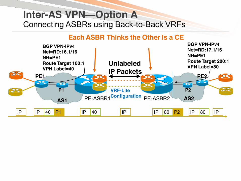
Each ASBR Thinks the Other Is a CE
Inter-AS VPN—Option AConnecting ASBRs using Back-to-Back VRFs
Two providers prefer not to share MPLS link
One logical interface per VPN/VRF on directly connected ASBRs;
Packet is forwarded as an IP packet between the ASBRs
Link may use any supported PE-CE routing protocol
IP QoS policies negotiated and configured manually on the ASBRs
Option A is the most secure and easiest to provision
May not be easy to manage as #s of VPNs grow
AS1 PE-ASBR1
PE1P1
Unlabeled IP Packets
AS2PE-ASBR2
PE2
P2P1
IP IP 40 P1 IP 40 IP IPIP 80 P2 IP 80
10
VRF-LiteConfiguration
BGP VPN-IPv4Net=RD:16.1/16NH=PE1Route Target 100:1VPN Label=40
BGP VPN-IPv4Net=RD:17.1/16NH=PE1Route Target 200:1VPN Label=80
© 2011 Cisco and/or its affiliates. All rights reserved. Cisco PublicBRKMPL-2105 1111
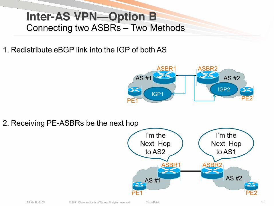
1. Redistribute eBGP link into the IGP of both AS
Inter-AS VPN—Option BConnecting two ASBRs – Two Methods
ASBR1 ASBR2
PE1 PE2
AS #1 AS #2
IGP2IGP1
11
ASBR1 ASBR2
PE1 PE2
AS #1 AS #2
I’m the Next Hop
to AS2
I’m the Next Hop
to AS1
2. Receiving PE-ASBRs be the next hop
© 2011 Cisco and/or its affiliates. All rights reserved. Cisco PublicBRKMPL-2105 12
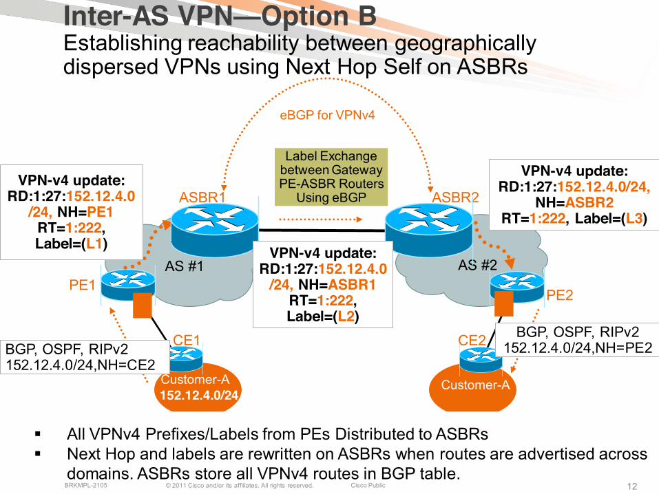
AS #1 AS #2PE1
PE2
Customer-A
CE1 CE2
Customer-A
ASBR1
152.12.4.0/24
BGP, OSPF, RIPv2 152.12.4.0/24,NH=CE2
VPN-v4 update:RD:1:27:152.12.4.0
/24, NH=PE1RT=1:222, Label=(L1)
VPN-v4 update:RD:1:27:152.12.4.0/24,
NH=ASBR2RT=1:222, Label=(L3)
BGP, OSPF, RIPv2 152.12.4.0/24,NH=PE2
Inter-AS VPN—Option BEstablishing reachability between geographically dispersed VPNs using Next Hop Self on ASBRs
ASBR2
All VPNv4 Prefixes/Labels from PEs Distributed to ASBRs Next Hop and labels are rewritten on ASBRs when routes are advertised across
domains. ASBRs store all VPNv4 routes in BGP table.
VPN-v4 update:RD:1:27:152.12.4.0
/24, NH=ASBR1RT=1:222, Label=(L2)
eBGP for VPNv4
Label Exchangebetween GatewayPE-ASBR Routers
Using eBGP
© 2011 Cisco and/or its affiliates. All rights reserved. Cisco PublicBRKMPL-2105 12
© 2011 Cisco and/or its affiliates. All rights reserved. Cisco PublicBRKMPL-2105 1313
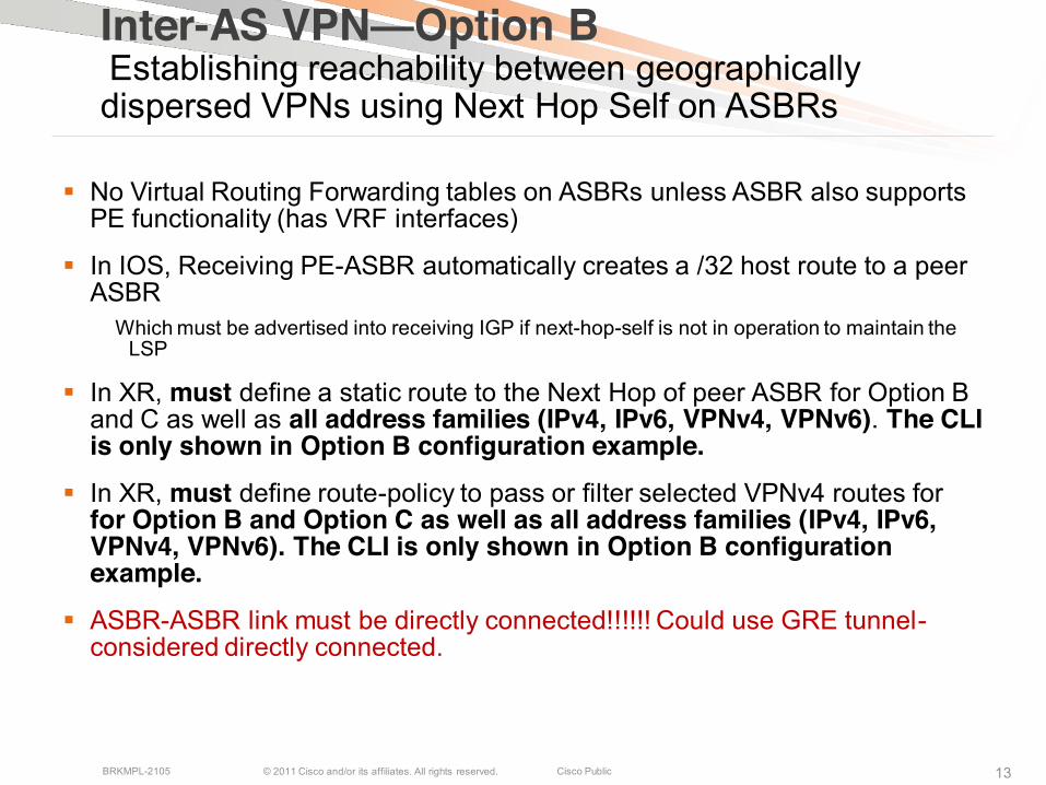
Inter-AS VPN—Option BEstablishing reachability between geographically dispersed VPNs using Next Hop Self on ASBRs
No Virtual Routing Forwarding tables on ASBRs unless ASBR also supports PE functionality (has VRF interfaces)
In IOS, Receiving PE-ASBR automatically creates a /32 host route to a peer ASBR
Which must be advertised into receiving IGP if next-hop-self is not in operation to maintain the LSP
In XR, must define a static route to the Next Hop of peer ASBR for Option B and C as well as all address families (IPv4, IPv6, VPNv4, VPNv6). The CLIis only shown in Option B configuration example.
In XR, must define route-policy to pass or filter selected VPNv4 routes for for Option B and Option C as well as all address families (IPv4, IPv6, VPNv4, VPNv6). The CLI is only shown in Option B configuration example.
ASBR-ASBR link must be directly connected!!!!!! Could use GRE tunnel-considered directly connected.
© 2011 Cisco and/or its affiliates. All rights reserved. Cisco PublicBRKMPL-2105 14
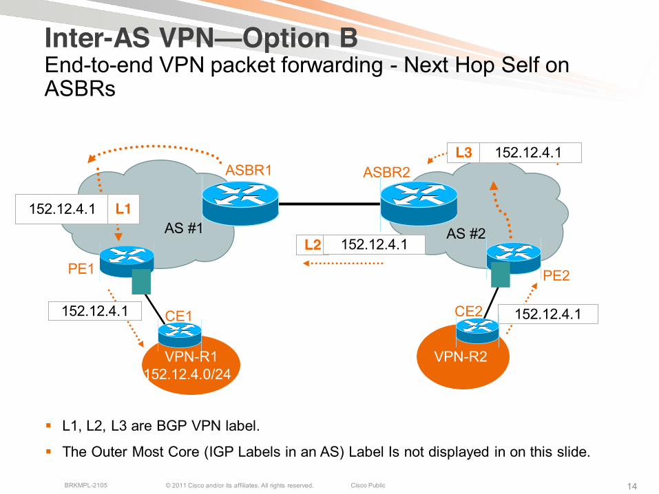
ASBR1 ASBR2
152.12.4.1
152.12.4.1L3
L2 152.12.4.1
152.12.4.1 L1
152.12.4.1
PE1
VPN-R1
CE1
152.12.4.0/24
PE2
CE2
VPN-R2
Inter-AS VPN—Option BEnd-to-end VPN packet forwarding - Next Hop Self on ASBRs
AS #1 AS #2
L1, L2, L3 are BGP VPN label.
The Outer Most Core (IGP Labels in an AS) Label Is not displayed in on this slide.
© 2011 Cisco and/or its affiliates. All rights reserved. Cisco PublicBRKMPL-2105 15
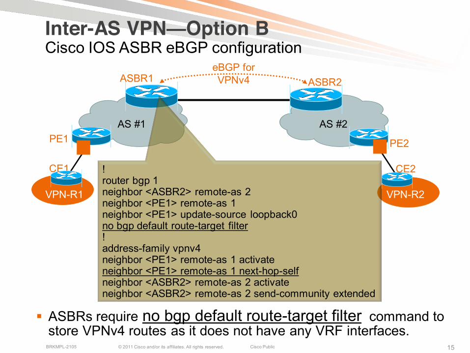
Inter-AS VPN—Option BCisco IOS ASBR eBGP configuration
PE1 PE2
AS #1 AS #2
CE1
VPN-R1 VPN-R2
CE2
ASBR1 ASBR2eBGP for VPNv4
!router bgp 1neighbor <ASBR2> remote-as 2neighbor <PE1> remote-as 1neighbor <PE1> update-source loopback0no bgp default route-target filter!address-family vpnv4neighbor <PE1> remote-as 1 activateneighbor <PE1> remote-as 1 next-hop-selfneighbor <ASBR2> remote-as 2 activateneighbor <ASBR2> remote-as 2 send-community extended
ASBRs require no bgp default route-target filter command to store VPNv4 routes as it does not have any VRF interfaces.
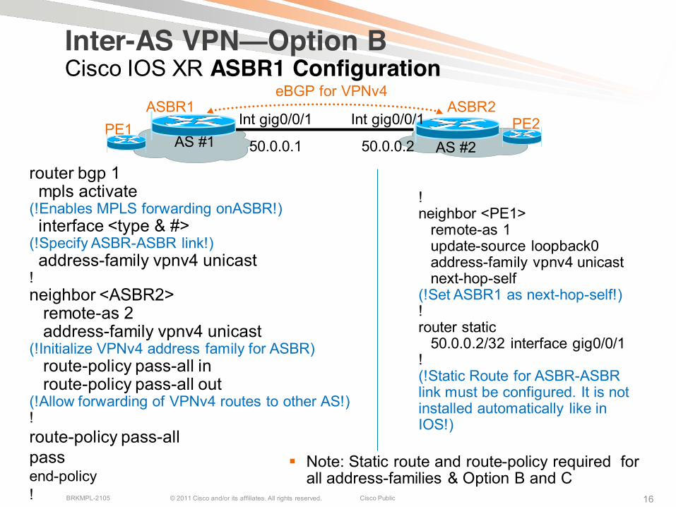
© 2011 Cisco and/or its affiliates. All rights reserved. Cisco PublicBRKMPL-2105 16
!neighbor <PE1>
remote-as 1update-source loopback0address-family vpnv4 unicastnext-hop-self
(!Set ASBR1 as next-hop-self!)!router static
50.0.0.2/32 interface gig0/0/1 !(!Static Route for ASBR-ASBRlink must be configured. It is not installed automatically like in IOS!)
PE1 PE2AS #1 AS #2
ASBR1 ASBR2eBGP for VPNv4
Int gig0/0/1
50.0.0.1
Int gig0/0/1
50.0.0.2
Inter-AS VPN—Option BCisco IOS XR ASBR1 Configuration
router bgp 1mpls activate
(!Enables MPLS forwarding onASBR!)interface <type & #>
(!Specify ASBR-ASBR link!)address-family vpnv4 unicast
!neighbor <ASBR2>
remote-as 2address-family vpnv4 unicast
(!Initialize VPNv4 address family for ASBR)route-policy pass-all inroute-policy pass-all out
(!Allow forwarding of VPNv4 routes to other AS!)!route-policy pass-allpassend-policy!
Note: Static route and route-policy required for all address-families & Option B and C

© 2011 Cisco and/or its affiliates. All rights reserved. Cisco PublicBRKMPL-2105 1717
Inter-AS VPN—Option CMultihop eBGP VPNv4 Between RRs for better scale
Route Reflectors exchange VPNv4 routes
ASBRs Exchange PE loopbacks (IPv4) with labels as these are BGP NH addresses
Eliminates LFIB duplication at ASBRs. ASBRsdon’t hold VPNv4 prefix/label info.
Two Options for Label Distribution for BGP NHAddresses for PEs in each domain:
1. BGP IPv4 + Labels (RFC3107) – most preferred & recommended
2. IGP + LDP
PE1
AS #2ASBR2
eBGPIPv4 + Labels
IGP + LDP
RR2RR1Exchange
VPNv4Routes
ASBR1
PE2
AS #1
BGP exchange Label Advertisement Capability -Enables end-end LSP Paths
Subsequent Address Family Identifier (SAFI value 4) field is used to indicate that the NLRIcontains a label
Disable Next-hop-self on eBGP RRs (peers)
© 2011 Cisco and/or its affiliates. All rights reserved. Cisco PublicBRKMPL-2105 18
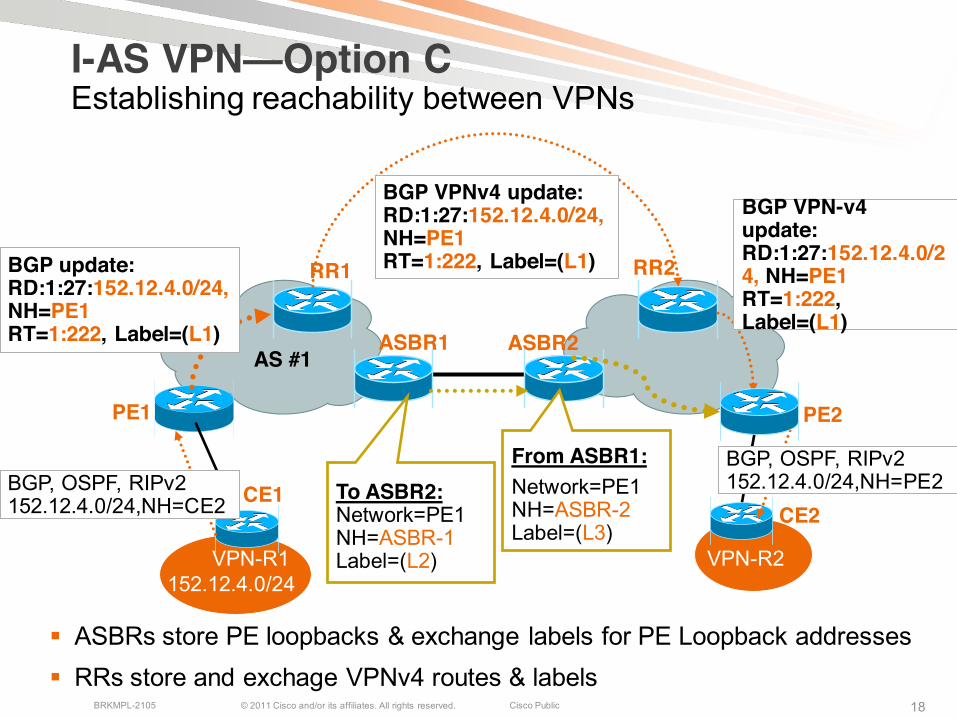
VPN-R1
CE1CE2
VPN-R2
ASBR1
RR2
ASBR2
BGP, OSPF, RIPv2 152.12.4.0/24,NH=CE2
BGP VPNv4 update:RD:1:27:152.12.4.0/24,NH=PE1RT=1:222, Label=(L1)
BGP VPN-v4 update:RD:1:27:152.12.4.0/24, NH=PE1RT=1:222, Label=(L1)
BGP, OSPF, RIPv2 152.12.4.0/24,NH=PE2
PE1 PE2
I-AS VPN—Option CEstablishing reachability between VPNs
AS #1
BGP update:RD:1:27:152.12.4.0/24,NH=PE1RT=1:222, Label=(L1)
To ASBR2:Network=PE1NH=ASBR-1Label=(L2)
From ASBR1:Network=PE1 NH=ASBR-2Label=(L3)
152.12.4.0/24
RR1
ASBRs store PE loopbacks & exchange labels for PE Loopback addresses RRs store and exchage VPNv4 routes & labels
© 2011 Cisco and/or its affiliates. All rights reserved. Cisco PublicBRKMPL-2105 19
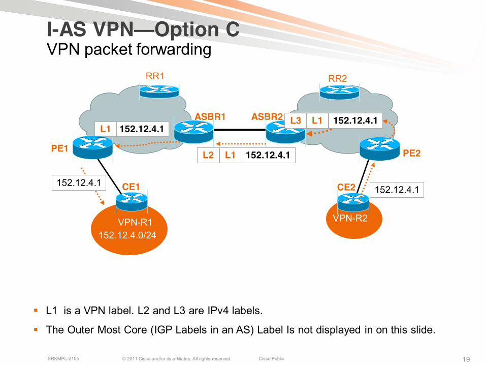
I-AS VPN—Option CVPN packet forwarding
VPN-R1
CE1 CE2
VPN-R2
ASBR1
RR2
ASBR2
RR1
PE1
152.12.4.1
L2 L1 152.12.4.1
152.12.4.1
PE2
L1L3 152.12.4.1152.12.4.1L1
152.12.4.0/24
L1 is a VPN label. L2 and L3 are IPv4 labels.
The Outer Most Core (IGP Labels in an AS) Label Is not displayed in on this slide.

© 2011 Cisco and/or its affiliates. All rights reserved. Cisco PublicBRKMPL-2105 20
ASBR1
RR2
ASBR2
RR1
PE1PE2
I-AS VPN—Option CIPv4+Label, Cisco IOS Configuration
!address-family ipv4neighbor <RR1> activateneighbor <RR1> send-label!
!router bgp 1neighbor <RR2> ebgp-multihop 255!address-family ipv4neighbor <RR2> activate
neighbor <PE1> activateneighbor <PE1> send-label
neighbor <ASBR1> activateneighbor <ASBR1> send-label!address-family vpnv4neighbor <RR2> next-hop-unchangedexit-address-family!
!address-family ipv4neighbor <ASBR2> activateneighbor <ASBR2> send-label
neighbor <RR1> activateneighbor <RR1> next-hop-selfneighbor <RR1> send-label!
AS #1
© 2011 Cisco and/or its affiliates. All rights reserved. Cisco PublicBRKMPL-2105 21
ASBR1
RR2
ASBR2
RR1
PE1PE2
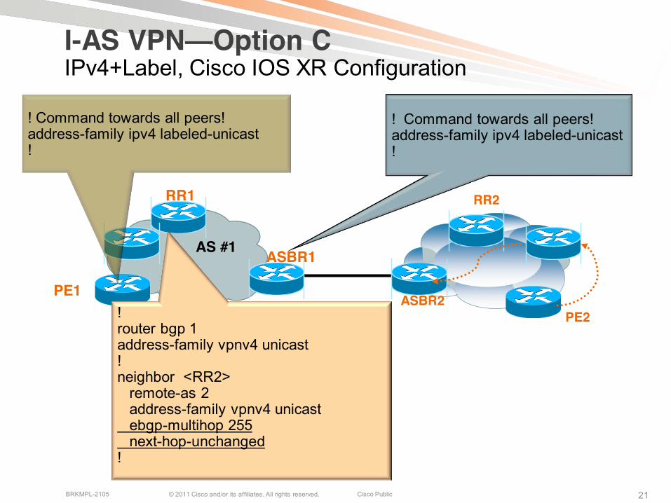
I-AS VPN—Option CIPv4+Label, Cisco IOS XR Configuration
! Command towards all peers!address-family ipv4 labeled-unicast!
!router bgp 1address-family vpnv4 unicast!neighbor <RR2>
remote-as 2address-family vpnv4 unicastebgp-multihop 255next-hop-unchanged
!
! Command towards all peers!address-family ipv4 labeled-unicast!
AS #1

© 2011 Cisco and/or its affiliates. All rights reserved. Cisco PublicBRKMPL-2105 2222
Inter-AS Multipath Load Balance Options
Support VPNv4 and label negotiated IPv4 eBGP sessions between loopbacks of directly connected routers w/o the use of LDP on the connecting interfaces
Consider the three topologies –Designated by Topo-1, Topo-2, Topo-3
Load balancing for Inter-AS sub-cases with:
1. Interface Peering2. Loopback peering3. IPv4 + Label4. VPNv4 + Label
ASBR1
ASBR1
ASBR3
ASBR2
ASBR2
Topo-1
Topo-2
Topo-3
AS1 AS2
ASBR1
ASBR3ASBR4
ASBR2

© 2011 Cisco and/or its affiliates. All rights reserved. Cisco PublicBRKMPL-2105 23
Inter-AS Loopback Peering for Directly Connected ASBRs
HOSTNAME ASBR2 (IOS configuration)!interface e0/0ip address 168.192.0.2 255.255.255.252 mpls bgp forwarding ! Enable BGP forwarding on connecting interfaces
!interface e2/0ip address 168.192.2.2 255.255.255.252 mpls bgp forwarding!router bgp 2neighbor 10.10.10.10 remote-as 1neighbor 10.10.10.10 disable-connected-check neighbor 10.10.10.10 update-source Loopback0!
PE2PE1 AS #1 AS #2
RR2RR1
ASBR-1 ASBR-2
E0/0: 168.192.0.1
E2/0: 168.192.2.1
L0:10.20.20.20/32L0:10.10.10.10
E2/0: 168.192.2.2
E0/0: 168.192.0.2
Create loopback interfaces on directly connected ASBRs
!address-family vpnv4neighbor 10.10.10.10 activate neighbor 10.10.10.10 send-community extended !ip route 10.10.10.10 255.255.255 e0/0 168.192.0.1 ip route 10.10.10.10 255.255.255 e2/0 168.192.2.1! Configure /32 static routes to the eBGP neighbor
loopback address
© 2011 Cisco and/or its affiliates. All rights reserved. Cisco PublicBRKMPL-2105 2424
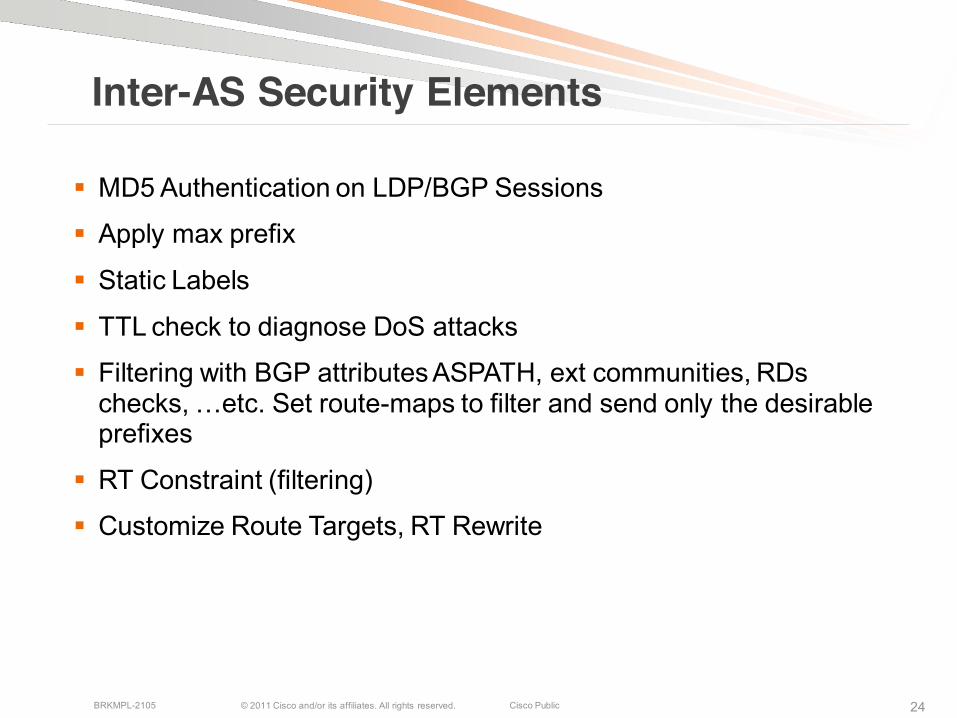
Inter-AS Security Elements
MD5 Authentication on LDP/BGP Sessions
Apply max prefix
Static Labels
TTL check to diagnose DoS attacks
Filtering with BGP attributes ASPATH, ext communities, RDs checks, …etc. Set route-maps to filter and send only the desirable prefixes
RT Constraint (filtering)
Customize Route Targets, RT Rewrite
© 2011 Cisco and/or its affiliates. All rights reserved. Cisco PublicBRKMPL-2105 2525
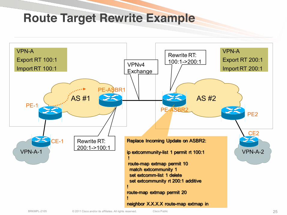
Route Target Rewrite Example
VPN-A-1 VPN-A-2
PE-1PE2
CE2
PE-ASBR1
PE-ASBR2
CE-1
AS #1 AS #2
VPN-AExport RT 100:1Import RT 100:1
VPN-AExport RT 200:1Import RT 200:1
Rewrite RT:200:1->100:1
Rewrite RT:100:1->200:1VPNv4
Exchange
Replace Incoming Update on ASBR2:
ip extcommunity-list 1 permit rt 100:1 ! route-map extmap permit 10 match extcommunity 1 set extcomm-list 1 delete set extcommunity rt 200:1 additive
! route-map extmap permit 20 !neighbor X.X.X.X route-map extmap in

© 2011 Cisco and/or its affiliates. All rights reserved. Cisco PublicBRKMPL-2105 2626
Inter-AS L3VPN Summary Three models: Option A, B, and C
Option A is the most secured, least invasive. Support granular QoS.
Option B, more scalable than Option-A for high numbers of VRFs. more adoptable by different provider corporations• Less invasive than Option C, More invasive than Option A
•More scalable than Option-A if have high numbers of VRFs
•Use eBGP for ASBR peering
•ASBRs store VPNv4 routes and allocate labels for VPN prefixes
Option C, most scalable, most invasive, mostly deployed in a single service provider’s multi-AS network•Use ASBRs to handle IPv4 PE loopbacks
•Route Reflectors exchange VPNv4 routes

© 2011 Cisco and/or its affiliates. All rights reserved. Cisco PublicBRKMPL-2105 27
Inter-AS IPV6 VPNs
© 2011 Cisco and/or its affiliates. All rights reserved. Cisco PublicBRKMPL-2105 28
ASBR1 ASBR2
6VPE1
VPN-R1
CE16VPE2
CE2
VPN-R2
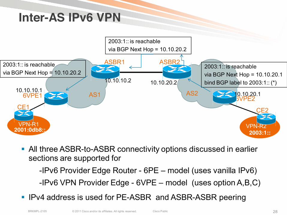
Inter-AS IPv6 VPN
2001:0db8:: 2003:1::
10.10.20.2
AS1 AS210.10.10.110.10.20.1
2003:1:: is reachable via BGP Next Hop = 10.10.20.1 bind BGP label to 2003:1:: (*)
All three ASBR-to-ASBR connectivity options discussed in earlier sections are supported for
-IPv6 Provider Edge Router - 6PE – model (uses vanilla IPv6)-IPv6 VPN Provider Edge - 6VPE – model (uses option A,B,C)
IPv4 address is used for PE-ASBR and ASBR-ASBR peering
2003:1:: is reachable via BGP Next Hop = 10.10.20.2
10.10.10.2
2003:1:: is reachable via BGP Next Hop = 10.10.20.2
© 2011 Cisco and/or its affiliates. All rights reserved. Cisco PublicBRKMPL-2105 29
ASBR1 ASBR2
6VPE1
VPN-R1
CE16VPE2
CE2
VPN-R2
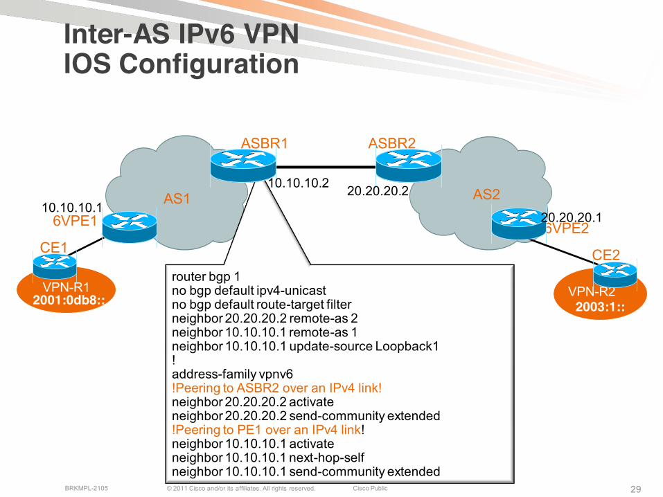
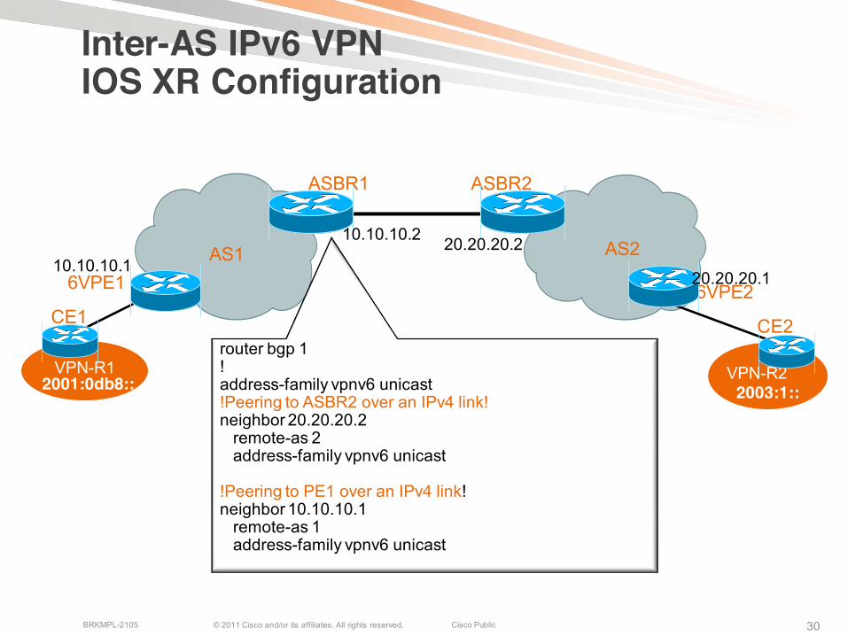
Inter-AS IPv6 VPNIOS Configuration
2001:0db8:: 2003:1::
router bgp 1no bgp default ipv4-unicastno bgp default route-target filter neighbor 20.20.20.2 remote-as 2neighbor 10.10.10.1 remote-as 1 neighbor 10.10.10.1 update-source Loopback1! address-family vpnv6!Peering to ASBR2 over an IPv4 link! neighbor 20.20.20.2 activate neighbor 20.20.20.2 send-community extended !Peering to PE1 over an IPv4 link!neighbor 10.10.10.1 activate neighbor 10.10.10.1 next-hop-self neighbor 10.10.10.1 send-community extended
20.20.20.2AS1 AS210.10.10.1
20.20.20.1
10.10.10.2
© 2011 Cisco and/or its affiliates. All rights reserved. Cisco PublicBRKMPL-2105 30
ASBR1 ASBR2
6VPE1
VPN-R1
CE16VPE2
CE2
VPN-R2
Inter-AS IPv6 VPNIOS XR Configuration
2001:0db8:: 2003:1::
router bgp 1! address-family vpnv6 unicast!Peering to ASBR2 over an IPv4 link! neighbor 20.20.20.2
remote-as 2address-family vpnv6 unicast
!Peering to PE1 over an IPv4 link!neighbor 10.10.10.1
remote-as 1address-family vpnv6 unicast
20.20.20.2AS1 AS210.10.10.1
20.20.20.1
10.10.10.2
© 2011 Cisco and/or its affiliates. All rights reserved. Cisco PublicBRKMPL-2105 31
Inter-AS L2 VPNs
© 2011 Cisco and/or its affiliates. All rights reserved. Cisco PublicBRKMPL-2105 3232
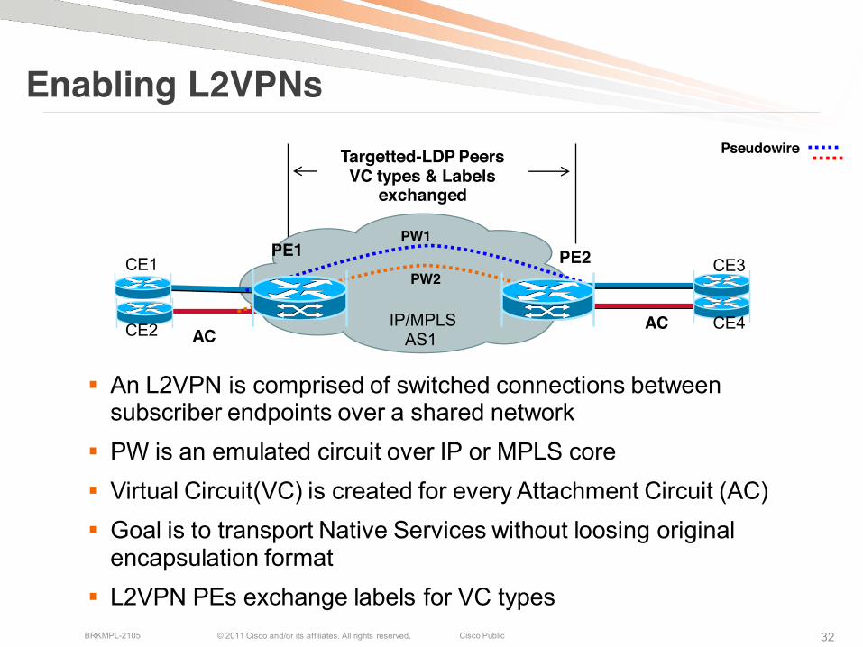
Enabling L2VPNsPseudowireTargetted-LDP Peers
VC types & Labels exchanged
An L2VPN is comprised of switched connections between subscriber endpoints over a shared network
PW is an emulated circuit over IP or MPLS core Virtual Circuit(VC) is created for every Attachment Circuit (AC) Goal is to transport Native Services without loosing original
encapsulation format L2VPN PEs exchange labels for VC types
IP/MPLSAS1
PE2PW2
PE1
AC
CE1
PW1
ACCE2
CE3
CE4
© 2011 Cisco and/or its affiliates. All rights reserved. Cisco PublicBRKMPL-2105 3333
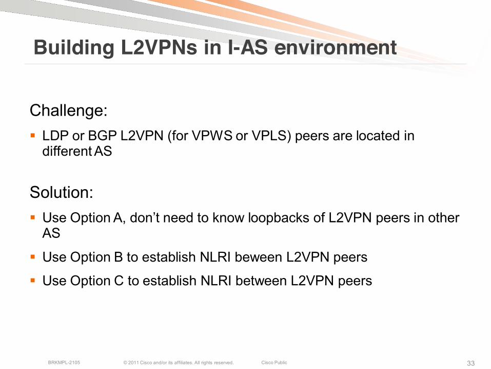
Building L2VPNs in I-AS environment
Challenge: LDP or BGP L2VPN (for VPWS or VPLS) peers are located in
different AS
Solution: Use Option A, don’t need to know loopbacks of L2VPN peers in other
AS
Use Option B to establish NLRI beween L2VPN peers
Use Option C to establish NLRI between L2VPN peers

© 2011 Cisco and/or its affiliates. All rights reserved. Cisco PublicBRKMPL-2105 3434
Inter-AS L2VPNMultiple PW Segments Using Option A
Any Transport over MPLS is a point-to-point L2VPN service
Need T-LDP sessions to build a PW. Need an IP address to build T-LDP session.
One PW/AC (AC types: Ethernet, VLAN, PPP, ATM, TDM, FR, HDLC)
Clear demarcation between ASs
PE-ASBR exchange PW (VC) label
Granular QoS control between ASBRs
IP/MPLSAS1
ASBR1 ASBR2
IP/MPLSAS2
..PW2
PW2PE1 PE2
ACAC
CE2CE1
PW1 PW1
AC
PL 40 PL 40 PL 80 PL 80
Pseudowire
PW LabelPL = Payload
T-LDP Peers
VC type & Label
T-LDP Peers
VC type & Label

© 2011 Cisco and/or its affiliates. All rights reserved. Cisco PublicBRKMPL-2105 3535
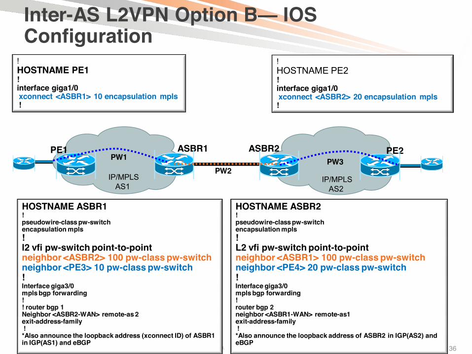
Inter-AS L2VPNMultihop PW Using Option B
PE and P devices do not learn remote PW endpoint addresses
Only PW endpoint address (ASBR) leaked between ASs
ASBRs swap PW (Virtual Circuit) Label
ASBR1 ASBR2PW1 PW3
PE1 PE2PW2
IP/MPLSAS1
IP/MPLSAS2
PL 40 PL 80 PL 80PL 10PL 40
T-LDP Peers T-LDP
Peers
T-LDPPeers
PW LabelsPL = Payload
© 2011 Cisco and/or its affiliates. All rights reserved. Cisco PublicBRKMPL-2105 36
Inter-AS L2VPN Option B— IOSConfiguration
!HOSTNAME PE1!interface giga1/0xconnect <ASBR1> 10 encapsulation mpls!
!HOSTNAME PE2!interface giga1/0xconnect <ASBR2> 20 encapsulation mpls!
HOSTNAME ASBR1!pseudowire-class pw-switchencapsulation mpls!l2 vfi pw-switch point-to-pointneighbor <ASBR2> 100 pw-class pw-switchneighbor <PE3> 10 pw-class pw-switch!Interface giga3/0mpls bgp forwarding!! router bgp 1Neighbor <ASBR2-WAN> remote-as 2exit-address-family! *Also announce the loopback address (xconnect ID) of ASBR1in IGP(AS1) and eBGP
HOSTNAME ASBR2!pseudowire-class pw-switchencapsulation mpls!L2 vfi pw-switch point-to-pointneighbor <ASBR1> 100 pw-class pw-switchneighbor <PE4> 20 pw-class pw-switch!Interface giga3/0mpls bgp forwarding!router bgp 2neighbor <ASBR1-WAN> remote-as1exit-address-family! *Also announce the loopback address of ASBR2 in IGP(AS2) and eBGP
ASBR1 ASBR2PW1 PW3
PE1 PE2
PW2IP/MPLS
AS1IP/MPLS
AS2
© 2011 Cisco and/or its affiliates. All rights reserved. Cisco PublicBRKMPL-2105 3737
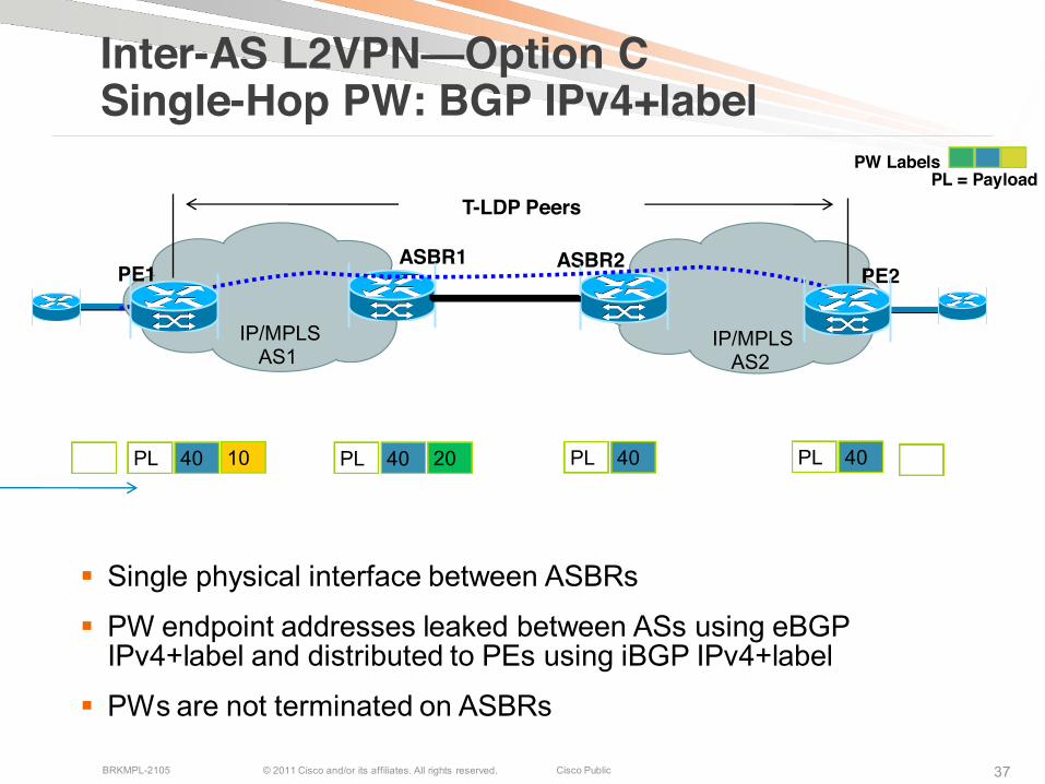
Inter-AS L2VPN—Option C Single-Hop PW: BGP IPv4+label
Single physical interface between ASBRs
PW endpoint addresses leaked between ASs using eBGPIPv4+label and distributed to PEs using iBGP IPv4+label
PWs are not terminated on ASBRs
ASBR1 ASBR2PE1 PE2
IP/MPLSAS1
IP/MPLSAS2
T-LDP Peers
1040PL 2040PL 40PL40PL
PW LabelsPL = Payload

© 2011 Cisco and/or its affiliates. All rights reserved. Cisco PublicBRKMPL-2105 38
Inter-AS AToM Option C—Configuration
HOSTNAME ASBR1! Activate IPv4 label capability !router bgp 1!address-family ipv4neighbor <PE3> send-labelneighbor <ASBR-2> send-labelexit-address-family!
HOSTNAME ASBR2! Activate IPv4 label capability !router bgp 2!address-family ipv4neighbor <PE4> send-labelneighbor <ASBR-1> send-labelexit-address-family!
HOSTNAME PE4!interface Gig1/1/1xconnect <PE3> 100 encapsulation mpls!! Activate IPv4 label capability !router bgp 2!address-family ipv4neighbor <ASBR-2> send-labelexit-address-family!
HOSTNAME PE3!interface Gig1/1/1xconnect <PE4> 100 encapsulation mpls! ! Activate IPv4 label capability !router bgp 1!address-family ipv4neighbor <ASBR-1> send-labelexit-address-family!
ASBR1 ASBR2PE3 PE4
IP/MPLSAS1
IP/MPLSAS2
T-LDP Peers
IntGig1/1/1
IntGig1/1/1
Notice PW configuration remains the same as in
intra-AS network
© 2011 Cisco and/or its affiliates. All rights reserved. Cisco PublicBRKMPL-2105 3939
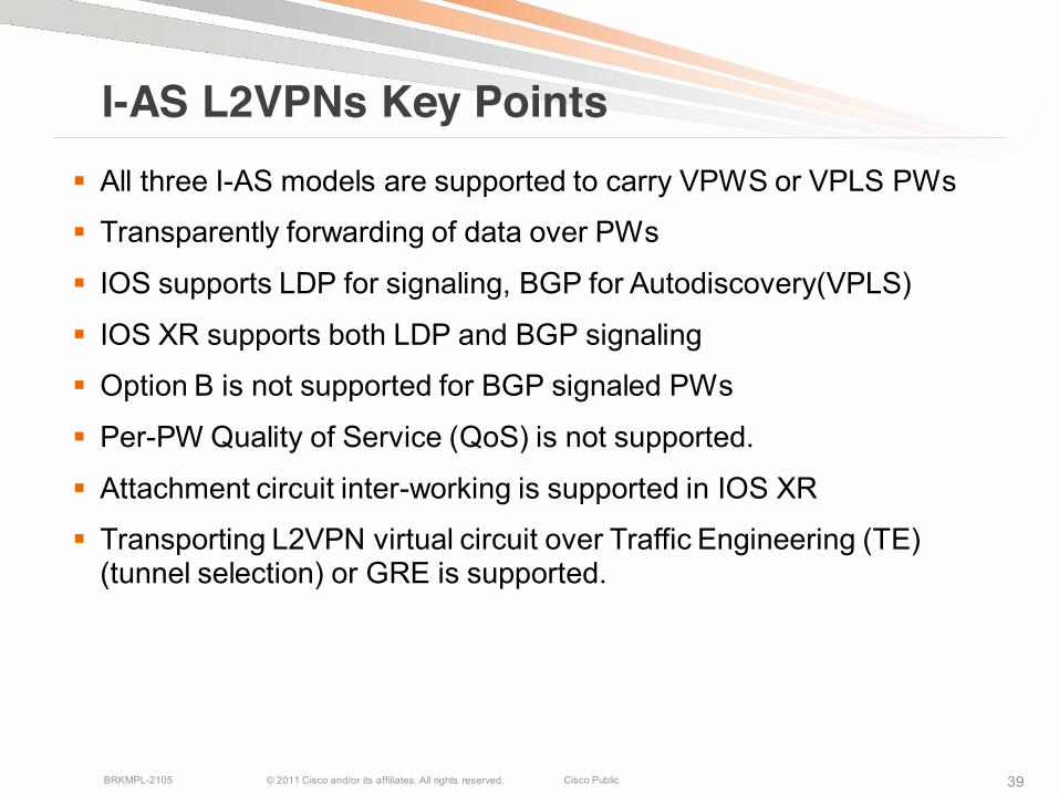
I-AS L2VPNs Key Points All three I-AS models are supported to carry VPWS or VPLS PWs
Transparently forwarding of data over PWs
IOS supports LDP for signaling, BGP for Autodiscovery(VPLS)
IOS XR supports both LDP and BGP signaling
Option B is not supported for BGP signaled PWs
Per-PW Quality of Service (QoS) is not supported.
Attachment circuit inter-working is supported in IOS XR
Transporting L2VPN virtual circuit over Traffic Engineering (TE) (tunnel selection) or GRE is supported.
© 2011 Cisco and/or its affiliates. All rights reserved. Cisco PublicBRKMPL-2105 40
Inter-AS mVPNs
© 2011 Cisco and/or its affiliates. All rights reserved. Cisco PublicBRKMPL-2105 4141
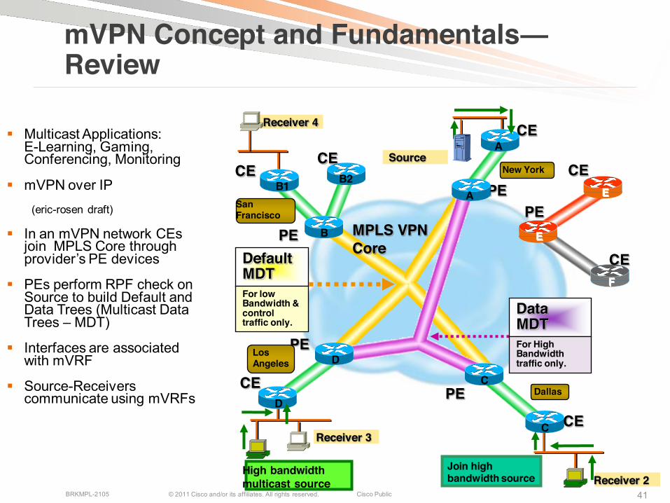
mVPN Concept and Fundamentals—Review
Multicast Applications: E-Learning, Gaming, Conferencing, Monitoring
mVPN over IP
(eric-rosen draft)
In an mVPN network CEsjoin MPLS Core through provider’s PE devices
PEs perform RPF check on Source to build Default and Data Trees (Multicast Data Trees – MDT)
Interfaces are associated with mVRF
Source-Receivers communicate using mVRFs
Receiver 4
B1
D
F
CE
A
CE
CE
High bandwidth multicast source
Receiver 3
Receiver 2
C
CE
CE
MPLS VPNCore
CE
Source
E
PEBPE
PE
E
PEA
PED
C
Join highbandwidth source
CE
DataMDTFor High Bandwidth traffic only.
DefaultMDTFor low Bandwidth & control traffic only.
B2
San Francisco
Los Angeles
Dallas
New York
© 2011 Cisco and/or its affiliates. All rights reserved. Cisco PublicBRKMPL-2105 4242
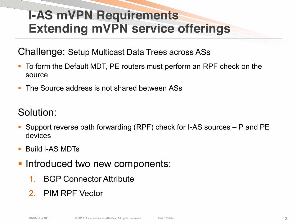
I-AS mVPN RequirementsExtending mVPN service offerings
Challenge: Setup Multicast Data Trees across ASs
To form the Default MDT, PE routers must perform an RPF check on the source
The Source address is not shared between ASs
Solution: Support reverse path forwarding (RPF) check for I-AS sources – P and PE
devices
Build I-AS MDTs
Introduced two new components:1. BGP Connector Attribute
2. PIM RPF Vector

© 2011 Cisco and/or its affiliates. All rights reserved. Cisco PublicBRKMPL-2105 4343
PE1 AS #1 AS #2
CE1
VPN-A1 VPN-A2CE4
ASBR1 ASBR2
MDTs
RPF Check with Option B and Option C
For Option B(eBGP between ASBRs): Use BGP Connector Attribute to RPF to source that is reachable via PE router in remote AS
Preserves identity of a PE router originating a VPNv4 Prefix
Receiving PEs in the remote AS use RPF Connector to resolve RPF
P11PE2
For Option B and C: Use PIM RPF Vector to help P routers build an I-AS MDT to Source PEs in remote AS
Leverage BGP MDT SAFI on ASBRs and receiver PEs to insert the RPF Vector needed to build an I-AS MDT to source PEs in remote ASs

© 2011 Cisco and/or its affiliates. All rights reserved. Cisco PublicBRKMPL-2105 44
PE1 PE2AS #1 AS #2
CE2
VPN-A1VPN-A2
CE-4
ASBR1
MDTs
I-AS MVPN MDT Establishment for Option Busing BGP connector attribute
P11
BGP VPNv4 Update from PE2 to ASBR2RD 1:1, Prefix 152.12.4.0/24 NH PE2, CONN PE2
BGP MDT SAFI Update (Source and Group)RD1:1, Prefix PE2, MDT 232.1.1.1, NH PE2
From ASBR2 to ASBR1RD 1:1, Prefix 152.12.4.0/24 NH ASBR2, CONN PE2
BGP MDT SAFI UpdateRD1:1, Prefix PE2, MDT 232.1.1.1, NH ASBR2
ASBR2
1.
2.
From ASBR1 to PE1RD 1:1, Prefix 152.12.4.0/24 NH ASBR1, CONN PE2
BGP MDT SAFI UpdateRD1:1, Prefix PE2, MDT 232.1.1.1, NH ASBR1
3.
© 2011 Cisco and/or its affiliates. All rights reserved. Cisco PublicBRKMPL-2105 45
PE1 PE2
AS #1 AS #2
ASBR1
MDTs
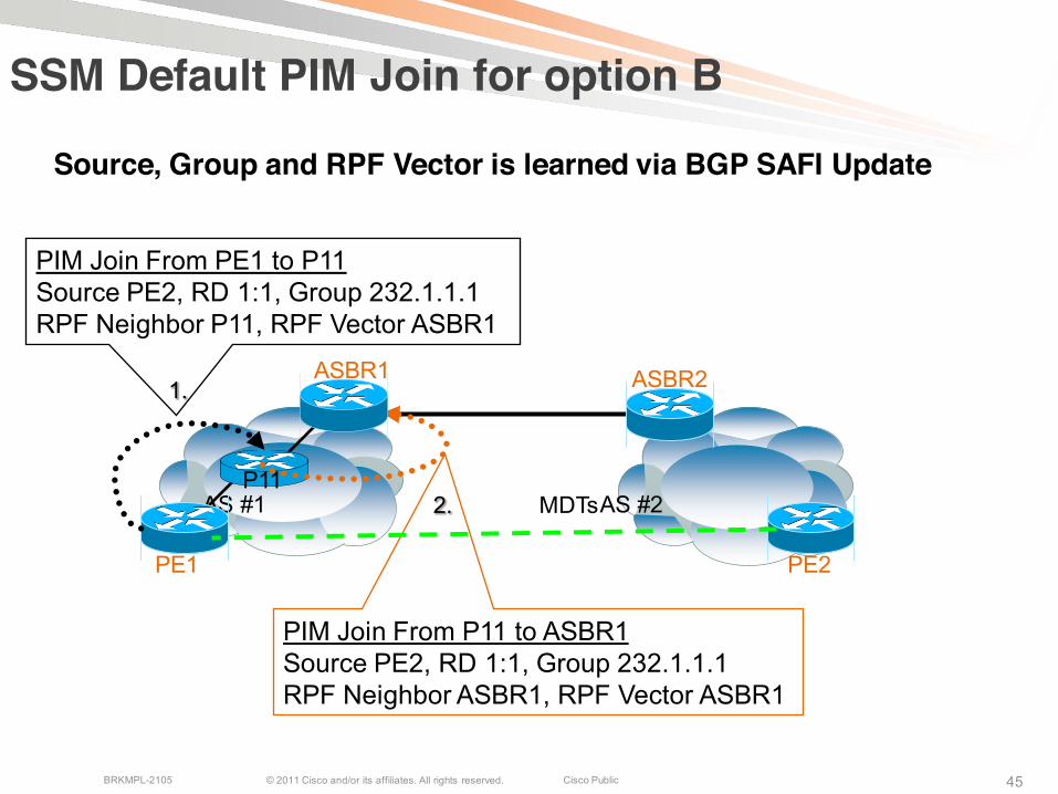
SSM Default PIM Join for option B
P11
PIM Join From P11 to ASBR1Source PE2, RD 1:1, Group 232.1.1.1RPF Neighbor ASBR1, RPF Vector ASBR1
ASBR2
2.
PIM Join From PE1 to P11Source PE2, RD 1:1, Group 232.1.1.1RPF Neighbor P11, RPF Vector ASBR1
1.
Source, Group and RPF Vector is learned via BGP SAFI Update
© 2011 Cisco and/or its affiliates. All rights reserved. Cisco PublicBRKMPL-2105 46
PE1 PE2AS #1 AS #2
ASBR1
MDTs
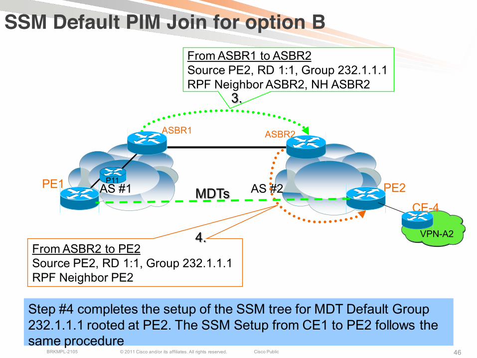
SSM Default PIM Join for option B
P11
From ASBR2 to PE2Source PE2, RD 1:1, Group 232.1.1.1RPF Neighbor PE2
ASBR2
4.
From ASBR1 to ASBR2Source PE2, RD 1:1, Group 232.1.1.1RPF Neighbor ASBR2, NH ASBR2
3.
Step #4 completes the setup of the SSM tree for MDT Default Group 232.1.1.1 rooted at PE2. The SSM Setup from CE1 to PE2 follows the same procedure
VPN-A2
CE-4
© 2011 Cisco and/or its affiliates. All rights reserved. Cisco PublicBRKMPL-2105 47
PE1PE2AS #1 AS #2
ASBR1
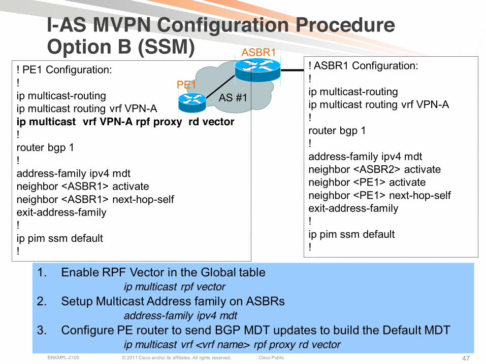
I-AS MVPN Configuration Procedure Option B (SSM)
ASBR2
1. Enable RPF Vector in the Global tableip multicast rpf vector
2. Setup Multicast Address family on ASBRsaddress-family ipv4 mdt
3. Configure PE router to send BGP MDT updates to build the Default MDT ip multicast vrf <vrf name> rpf proxy rd vector
CE-4
! PE1 Configuration:!ip multicast-routingip multicast routing vrf VPN-Aip multicast vrf VPN-A rpf proxy rd vector!router bgp 1!address-family ipv4 mdtneighbor <ASBR1> activateneighbor <ASBR1> next-hop-selfexit-address-family!ip pim ssm default!
! ASBR1 Configuration:!ip multicast-routingip multicast routing vrf VPN-A!router bgp 1!address-family ipv4 mdtneighbor <ASBR2> activateneighbor <PE1> activateneighbor <PE1> next-hop-selfexit-address-family!ip pim ssm default!
© 2011 Cisco and/or its affiliates. All rights reserved. Cisco PublicBRKMPL-2105 48
Agenda
Inter-AS NetworksInter-AS Connectivity ModelsInter-AS L3 VPNsInter-AS L2VPNsInter-AS Multicast VPNs
Carrier Supporting Carrier
CSC Service ModelsMPLS L3 VPNsMulticast VPNsMPLS L2 VPNs
Inter-AS RSVP-TE

© 2011 Cisco and/or its affiliates. All rights reserved. Cisco PublicBRKMPL-2105 4949
Carrier Supporting Carrier Use Cases
San FranciscoTier 2 or 3 ISP
Site 1
San FranciscoTier 2 or 3 ISP
Site 1
MPLS NWMPLS NW
How can Tier 2 or Tier 3 MPLS VPN service providers interconnect remote sites without self managing own MPLS WAN
MPLSBackbone
How can a corporation (enterprise network) MPLS VPN service providers interconnect remote sites without self managing own MPLS WAN
New YorkEnterprise MPLSVPN NW
Las VegasEnterprise MPLSVPN NW
MPLSBackbone
© 2011 Cisco and/or its affiliates. All rights reserved. Cisco PublicBRKMPL-2105 5050
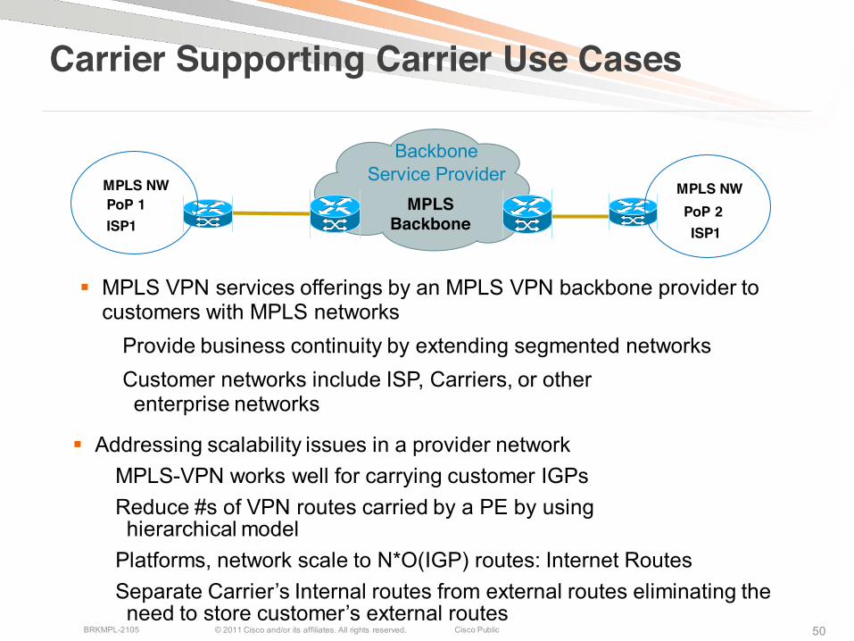
Carrier Supporting Carrier Use Cases
Addressing scalability issues in a provider networkMPLS-VPN works well for carrying customer IGPsReduce #s of VPN routes carried by a PE by using hierarchical model
Platforms, network scale to N*O(IGP) routes: Internet RoutesSeparate Carrier’s Internal routes from external routes eliminating the need to store customer’s external routes
MPLSBackbone
Backbone Service Provider
PoP 1MPLS NWMPLS NW
PoP 2
MPLS VPN services offerings by an MPLS VPN backbone provider to customers with MPLS networks
Provide business continuity by extending segmented networks Customer networks include ISP, Carriers, or other enterprise networks
ISP1 ISP1
© 2011 Cisco and/or its affiliates. All rights reserved. Cisco PublicBRKMPL-2105 51
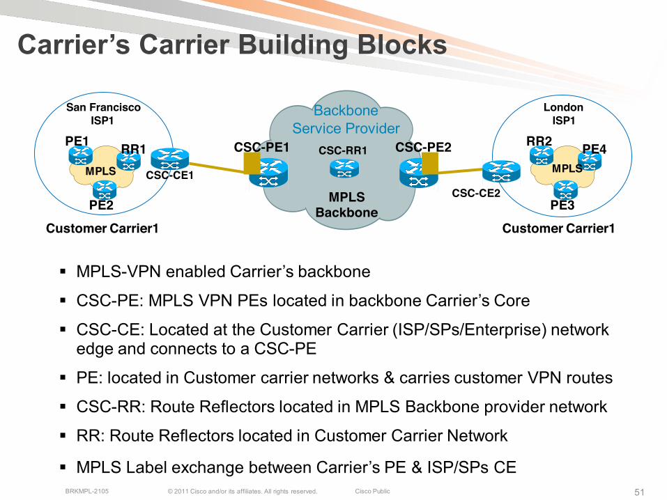
Carrier’s Carrier Building Blocks
MPLS-VPN enabled Carrier’s backbone
CSC-PE: MPLS VPN PEs located in backbone Carrier’s Core
CSC-CE: Located at the Customer Carrier (ISP/SPs/Enterprise) network edge and connects to a CSC-PE
PE: located in Customer carrier networks & carries customer VPN routes
CSC-RR: Route Reflectors located in MPLS Backbone provider network
RR: Route Reflectors located in Customer Carrier Network
MPLS Label exchange between Carrier’s PE & ISP/SPs CE
MPLS Backbone
CSC-PE1 CSC-PE2
CSC-CE2
Backbone Service Provider
CSC-CE1
San FranciscoISP1
LondonISP1
PE1 RR1
PE2
RR2 PE4
PE3
MPLSMPLS
CSC-RR1
Customer Carrier1 Customer Carrier1
© 2011 Cisco and/or its affiliates. All rights reserved. Cisco PublicBRKMPL-2105 52
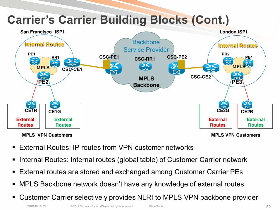
Carrier’s Carrier Building Blocks (Cont.)
External Routes: IP routes from VPN customer networks
Internal Routes: Internal routes (global table) of Customer Carrier network
External routes are stored and exchanged among Customer Carrier PEs
MPLS Backbone network doesn’t have any knowledge of external routes
Customer Carrier selectively provides NLRI to MPLS VPN backbone provider
MPLS Backbone
CSC-PE1 CSC-PE2
CSC-CE2
Backbone Service Provider
CSC-CE1
San Francisco ISP1 London ISP1
PE1RR1
PE2
RR2PE4
PE3
MPLSMPLS
CSC-RR1
CE1R CE1G
MPLS VPN Customers
External Routes
External Routes
CE2G CE2R
MPLS VPN Customers
External Routes
External Routes
Internal Routes Internal Routes
© 2011 Cisco and/or its affiliates. All rights reserved. Cisco PublicBRKMPL-2105 53
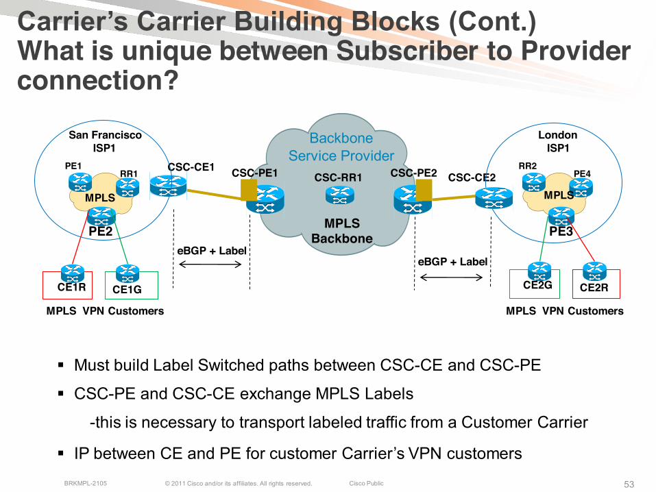
Carrier’s Carrier Building Blocks (Cont.)What is unique between Subscriber to Provider connection?
Must build Label Switched paths between CSC-CE and CSC-PE
CSC-PE and CSC-CE exchange MPLS Labels
-this is necessary to transport labeled traffic from a Customer Carrier
IP between CE and PE for customer Carrier’s VPN customers
MPLS Backbone
CSC-PE1 CSC-PE2 CSC-CE2
Backbone Service Provider
CSC-CE1
San FranciscoISP1
LondonISP1
PE1RR1
PE2
RR2PE4
PE3
MPLSMPLS
CSC-RR1
CE1R CE1G CE2G CE2R
eBGP + LabeleBGP + Label
MPLS VPN Customers MPLS VPN Customers
© 2011 Cisco and/or its affiliates. All rights reserved. Cisco PublicBRKMPL-2105 5454
CSC Building Blocks (Cont.)
Control Plane configuration is similar to single domain MPLS VPN CSC-CE to CSC-PE is a VPN link to exchange Customer Carrier’s
internal routes. These routes are redistributed into the BSP’s CSC-PE using:
1. Static Routes OR 2. Dynamic IGP OR 3. eBGP
Customer Carriers don’t exchange their Subscribers’ (external) VPN routes with the Backbone Service Provider
CSC-PE-to-CSC-CE links extend Label Switching Path using:1. IGP+LDP2. eBGPv4 + Labels
© 2011 Cisco and/or its affiliates. All rights reserved. Cisco PublicBRKMPL-2105 5555
Carrier Supporting Carrier Models
1. Customer Carrier Is Running IP Only-similar to basic MPLS L3 VPN environment
2. Customer Carrier Is Running MPLS-LSP is established between CSC-CE and CSC-PE
-Customer carrier is VPN subscriber of MPLS VPN backbone provider
3. Customer Carrier Supports MPLS VPNs-LSP is established between CSC-CE and CSC-PE
-Customer carrier is VPN subscriber of MPLS VPN backbone provider
-True hierarchical VPN model
© 2011 Cisco and/or its affiliates. All rights reserved. Cisco PublicBRKMPL-2105 5656
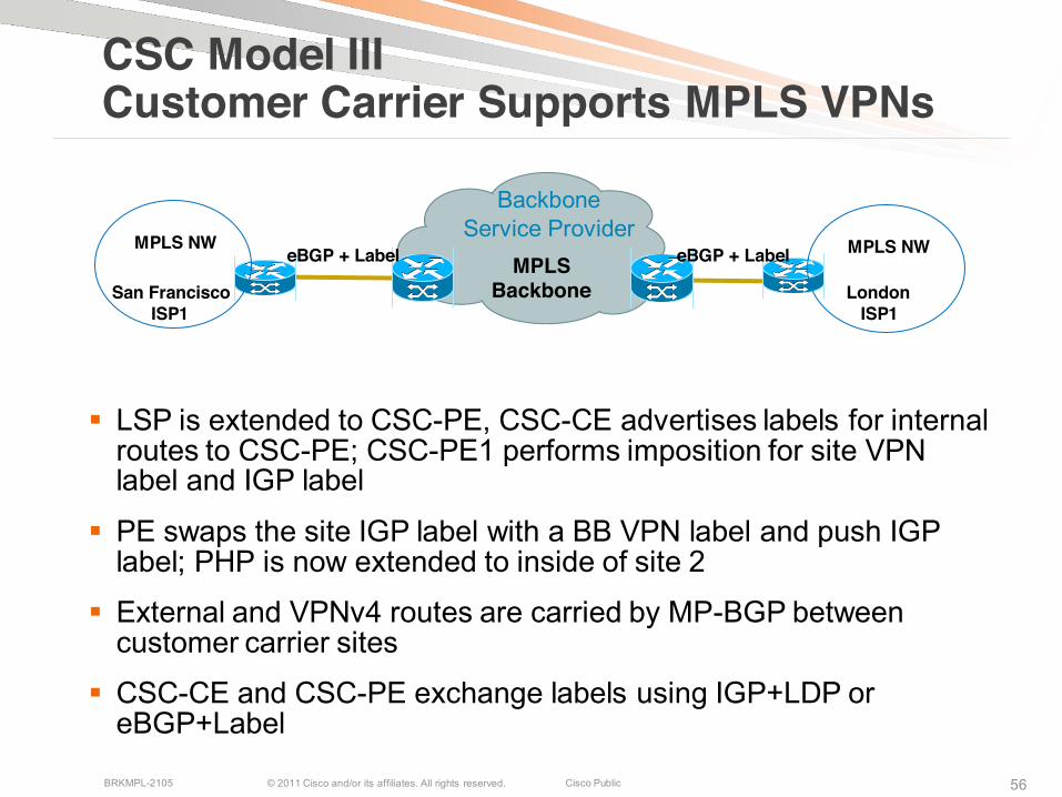
CSC Model IIICustomer Carrier Supports MPLS VPNs
LSP is extended to CSC-PE, CSC-CE advertises labels for internal routes to CSC-PE; CSC-PE1 performs imposition for site VPNlabel and IGP label
PE swaps the site IGP label with a BB VPN label and push IGPlabel; PHP is now extended to inside of site 2
External and VPNv4 routes are carried by MP-BGP between customer carrier sites
CSC-CE and CSC-PE exchange labels using IGP+LDP or eBGP+Label
MPLS Backbone
Backbone Service Provider
San FranciscoISP1
LondonISP1
MPLS NWMPLS NWeBGP + Label eBGP + Label
© 2011 Cisco and/or its affiliates. All rights reserved. Cisco PublicBRKMPL-2105 57
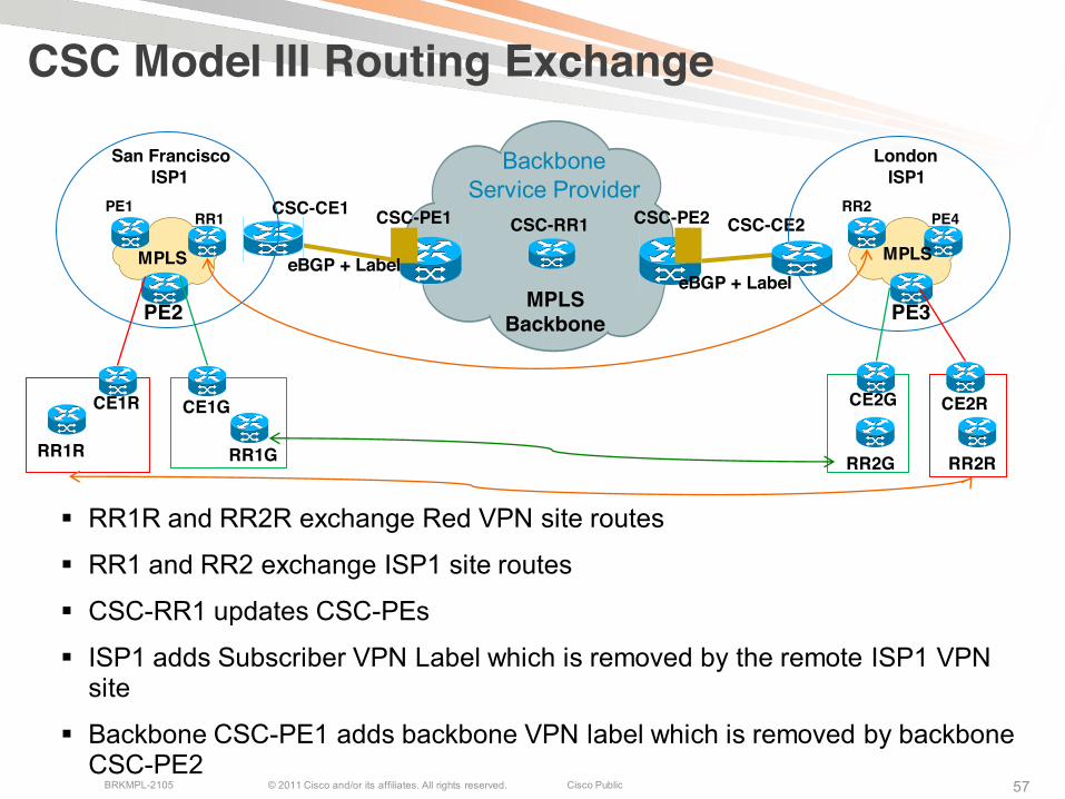
CSC Model III Routing Exchange
RR1R and RR2R exchange Red VPN site routes
RR1 and RR2 exchange ISP1 site routes
CSC-RR1 updates CSC-PEs
ISP1 adds Subscriber VPN Label which is removed by the remote ISP1 VPNsite
Backbone CSC-PE1 adds backbone VPN label which is removed by backbone CSC-PE2
MPLS Backbone
CSC-PE1 CSC-PE2 CSC-CE2
Backbone Service Provider
CSC-CE1
San FranciscoISP1
LondonISP1
PE1RR1
PE2
RR2PE4
PE3
MPLSMPLS
CSC-RR1
CE1R CE1G CE2G CE2R
RR1RRR2RRR2GRR1G
eBGP + LabeleBGP + Label
© 2011 Cisco and/or its affiliates. All rights reserved. Cisco PublicBRKMPL-2105 58
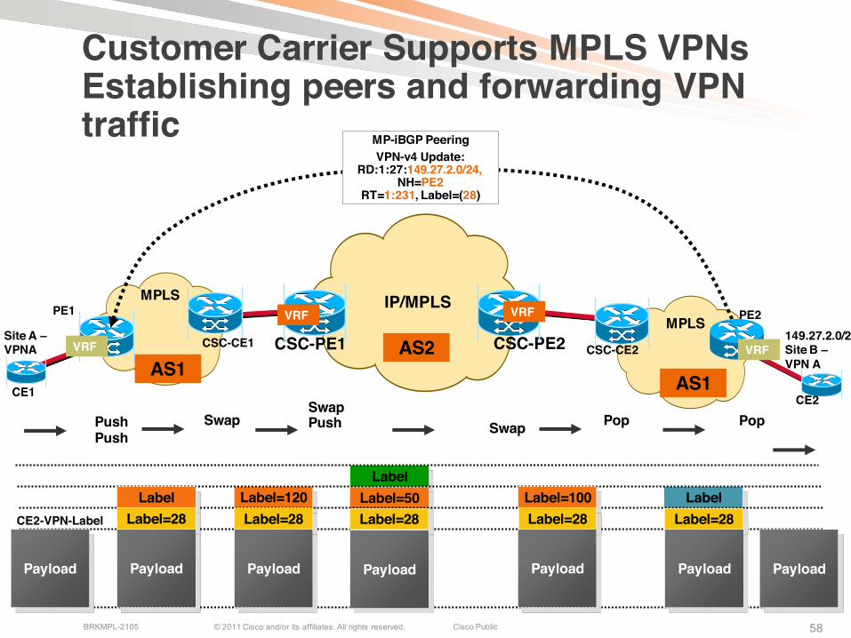
Customer Carrier Supports MPLS VPNsEstablishing peers and forwarding VPNtraffic
CSC-PE1 CSC-PE2
PE1
Site A –VPNA
149.27.2.0/24Site B –VPN A
CE1 CE2
MP-iBGP PeeringVPN-v4 Update:
RD:1:27:149.27.2.0/24,NH=PE2
RT=1:231, Label=(28)
PE2VRF VRFIP/MPLS
VRF CSC-CE2CSC-CE1
LabelLabel=120Label
Label=50 Label=100
SwapPushPush Swap Pop
LabelLabel=28
Payload
Label=28
Payload
Label=28
PayloadPayload
Label=28
Payload
SwapPush
Label=28
Payload
Pop
Payload
CE2-VPN-Label
AS1AS1
AS2
MPLS
MPLS
VRF
© 2011 Cisco and/or its affiliates. All rights reserved. Cisco PublicBRKMPL-2105 59
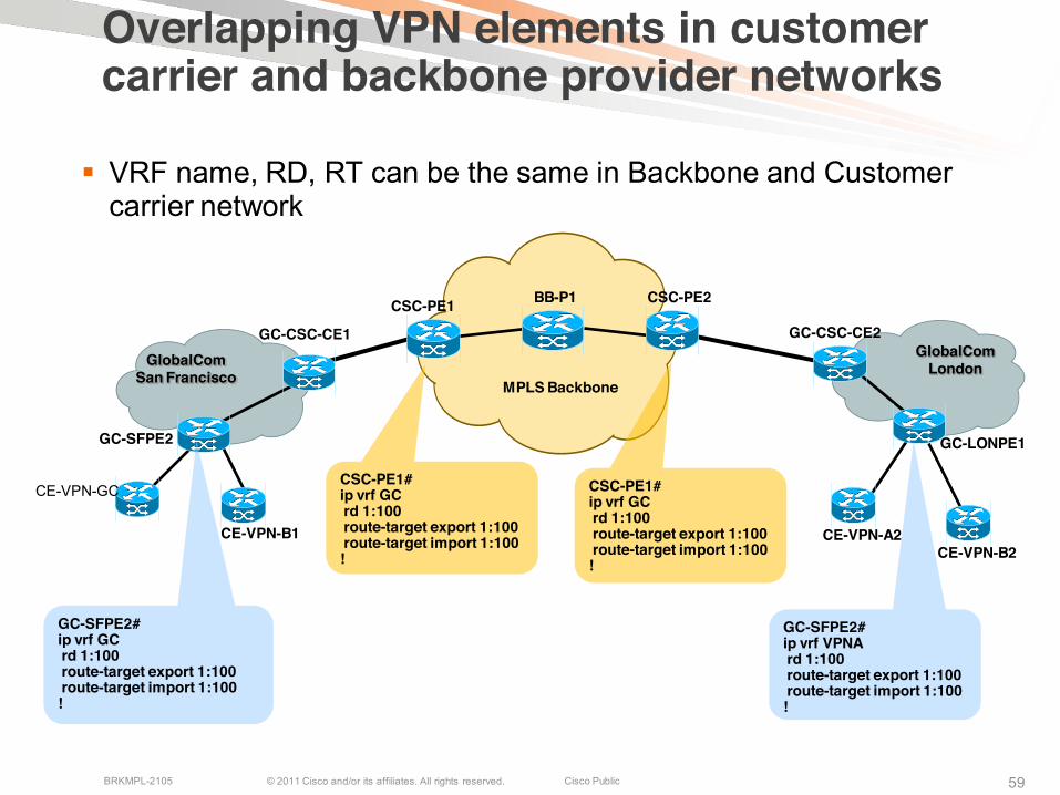
Overlapping VPN elements in customer carrier and backbone provider networks
MPLS Backbone
CSC-PE1 CSC-PE2
GlobalComSan Francisco
GlobalComLondon
GC-CSC-CE1 GC-CSC-CE2
GC-LONPE1GC-SFPE2
CE-VPN-GC
CE-VPN-B1 CE-VPN-A2CE-VPN-B2
BB-P1
CSC-PE1#ip vrf GCrd 1:100route-target export 1:100route-target import 1:100!
CSC-PE1#ip vrf GCrd 1:100route-target export 1:100route-target import 1:100!
GC-SFPE2#ip vrf GCrd 1:100route-target export 1:100route-target import 1:100!
GC-SFPE2#ip vrf VPNArd 1:100route-target export 1:100route-target import 1:100!
VRF name, RD, RT can be the same in Backbone and Customer carrier network
© 2011 Cisco and/or its affiliates. All rights reserved. Cisco PublicBRKMPL-2105 6060
CSC Security Elements
MD5 authentication on LDP/BGP sessions
Applying max prefix limits per VRF
Use of static labels between CSC-CE and CSC-PE
Route Filtering…Customer Carrier may not want to send all the internal routes to MPLS VPNbackbone provider…
Use Route-maps (IOS) with match and set capabilities in route-maps
Use route-policy (XR) to control route distribution & filter routes
© 2011 Cisco and/or its affiliates. All rights reserved. Cisco PublicBRKMPL-2105 6161
Services support over a CSC network
MPLS IPV4 VPNs
MPLS IPV6 VPNs
mVPNs-for PIM require native multicast in the provider network
RSVP-TE
MPLS L2VPNs
© 2011 Cisco and/or its affiliates. All rights reserved. Cisco PublicBRKMPL-2105 62
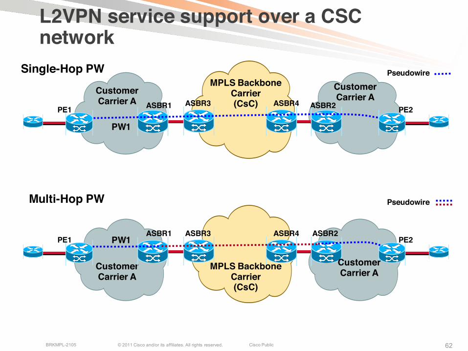
Customer Carrier A
ASBR1 ASBR2PW1PE1 PE2
ASBR3 ASBR4
L2VPN service support over a CSC network
ASBR1 ASBR2
PW1
PE1 PE2ASBR3 ASBR4
Multi-Hop PW
Single-Hop PW Pseudowire
Pseudowire
MPLS Backbone Carrier(CsC)
MPLS Backbone Carrier(CsC)
Customer Carrier A
Customer Carrier A
Customer Carrier A
© 2011 Cisco and/or its affiliates. All rights reserved. Cisco PublicBRKMPL-2105 6363
Best Practice Recommendations
Do not use Static default routes on CSC-CEEnd-End LSP is required across the VPN and MPLS VPN backbone
Use dynamic protocol instead of static on CSC-CE – CSC-PE link preferably eBGP+IPv4 Labels
Set Next-Hop-Self on ASBRs carrying external routes
If using IGP on CSC-CE routers, use filters to limit incoming routes from the CSC-PE side
If using RRs in customer carrier network, set next-hop-unchanged on RRs
© 2011 Cisco and/or its affiliates. All rights reserved. Cisco PublicBRKMPL-2105 6464
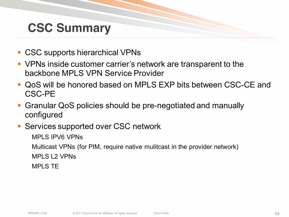
CSC Summary
CSC supports hierarchical VPNs VPNs inside customer carrier’s network are transparent to the
backbone MPLS VPN Service Provider QoS will be honored based on MPLS EXP bits between CSC-CE and
CSC-PE Granular QoS policies should be pre-negotiated and manually
configured Services supported over CSC network
MPLS IPV6 VPNsMulticast VPNs (for PIM, require native mulitcast in the provider network)MPLS L2 VPNsMPLS TE
© 2011 Cisco and/or its affiliates. All rights reserved. Cisco PublicBRKMPL-2105 65
Agenda
Inter-AS NetworksInter-AS Connectivity ModelsInter-AS L3 VPNsInter-AS L2VPNsInter-AS Multicast VPNs
Carrier Supporting Carrier
CSC Service ModelsMPLS L3 VPNsMulticast VPNsMPLS L2 VPNs
Inter-AS RSVP-TE
© 2011 Cisco and/or its affiliates. All rights reserved. Cisco PublicBRKMPL-2105 66
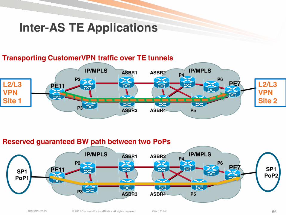
Inter-AS TE Applications
IP/MPLS ASBR1 ASBR2 IP/MPLS
PE11 PE7
ASBR3 ASBR4
P2
P3
P4
P5
P6
SP1PoP1
SP1PoP2
Reserved guaranteed BW path between two PoPs
IP/MPLS ASBR1 ASBR2 IP/MPLS
PE11 PE7
ASBR3 ASBR4
P2
P3
P4
P5
P6
Transporting CustomerVPN traffic over TE tunnels
L2/L3VPNSite 1
L2/L3VPNSite 2
© 2011 Cisco and/or its affiliates. All rights reserved. Cisco PublicBRKMPL-2105 67
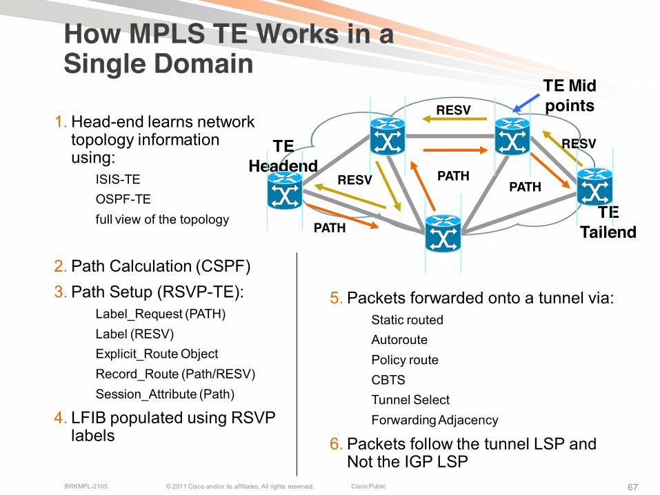
How MPLS TE Works in a Single Domain
1. Head-end learns network topology information using:
ISIS-TEOSPF-TEfull view of the topology
2. Path Calculation (CSPF)3. Path Setup (RSVP-TE):
Label_Request (PATH)Label (RESV)Explicit_Route ObjectRecord_Route (Path/RESV)Session_Attribute (Path)
4. LFIB populated using RSVP labels
5. Packets forwarded onto a tunnel via:Static routedAutoroutePolicy routeCBTS Tunnel SelectForwarding Adjacency
6. Packets follow the tunnel LSP and Not the IGP LSP
TE Headend
TE TailendPATH
PATHPATH
RESV
RESV
RESV
TE Mid points

© 2011 Cisco and/or its affiliates. All rights reserved. Cisco PublicBRKMPL-2105 6868
Inter-Domain Traffic Engineering
Challenge:
Head end and Tail end are located in different domains
IGP information is not shared between domains
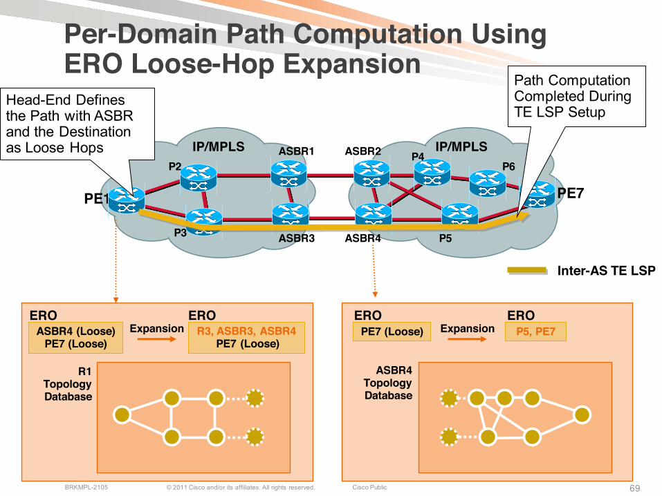
Head end lacks the knowledge of complete network topology to perform path computation
Solution:
Use Explicit Route Object (ERO) Loose Hop Expansion, Node-id, and Path re-evaluation request/reply Flags to provide per-domain path computation at the head-end + RSVP Policy Control and Confidentiality
RFCs: 3209, 4736, 4561, …etc.draft-ietf-ccamp-inter-domain-rsvp-te-06.txt draft-ietf-ccamp-inter-domain-pd-path-comp-05.txt
http://www.cisco.com/go/mpls
© 2011 Cisco and/or its affiliates. All rights reserved. Cisco PublicBRKMPL-2105 69
Per-Domain Path Computation Using ERO Loose-Hop Expansion
IP/MPLS ASBR1 ASBR2 IP/MPLS
PE11 PE7
ASBR3 ASBR4
P2
P3
P4
P5
P6
ASBR4 (Loose) PE7 (Loose)
R3, ASBR3, ASBR4PE7 (Loose)
R1 Topology Database
ERO EROExpansion
ERO EROP5, PE7PE7 (Loose)
ASBR4 Topology Database
Expansion
Inter-AS TE LSP
Head-End Defines the Path with ASBR and the Destination as Loose Hops
Path Computation Completed During TE LSP Setup
© 2011 Cisco and/or its affiliates. All rights reserved. Cisco PublicBRKMPL-2105 7070
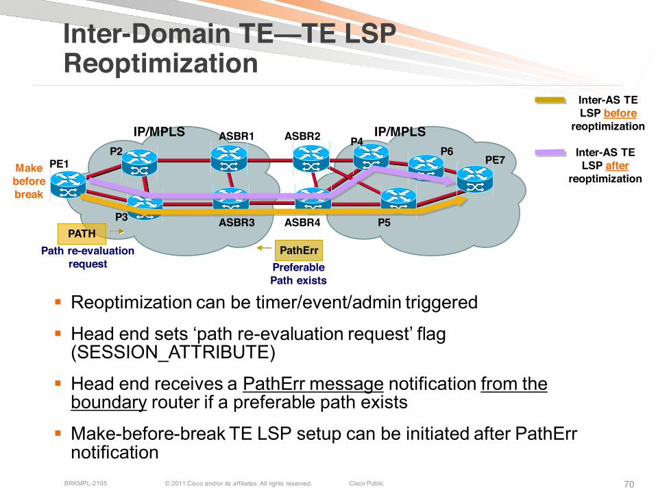
Inter-Domain TE—TE LSP Reoptimization
Reoptimization can be timer/event/admin triggered
Head end sets ‘path re-evaluation request’ flag (SESSION_ATTRIBUTE)
Head end receives a PathErr message notification from the boundary router if a preferable path exists
Make-before-break TE LSP setup can be initiated after PathErr notification
IP/MPLS ASBR1 ASBR2 IP/MPLS
PE1 PE7
ASBR3 ASBR4
P2
P3
P4
P5
P6 Inter-AS TE LSP after
reoptimization
Inter-AS TE LSP before
reoptimization
Make before break
Path re-evaluation request Preferable
Path exists
PATHPathErr
© 2011 Cisco and/or its affiliates. All rights reserved. Cisco PublicBRKMPL-2105 7171
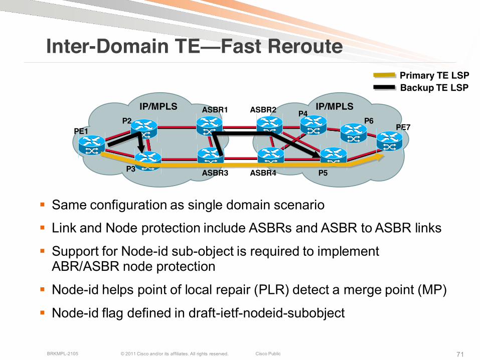
Inter-Domain TE—Fast Reroute
Same configuration as single domain scenario
Link and Node protection include ASBRs and ASBR to ASBR links
Support for Node-id sub-object is required to implement ABR/ASBR node protection
Node-id helps point of local repair (PLR) detect a merge point (MP)
Node-id flag defined in draft-ietf-nodeid-subobject
IP/MPLS ASBR1 ASBR2 IP/MPLS
PE1 PE7
ASBR3 ASBR4
P2
P3
P4
P5
P6
Primary TE LSPBackup TE LSP
© 2011 Cisco and/or its affiliates. All rights reserved. Cisco PublicBRKMPL-2105 7272
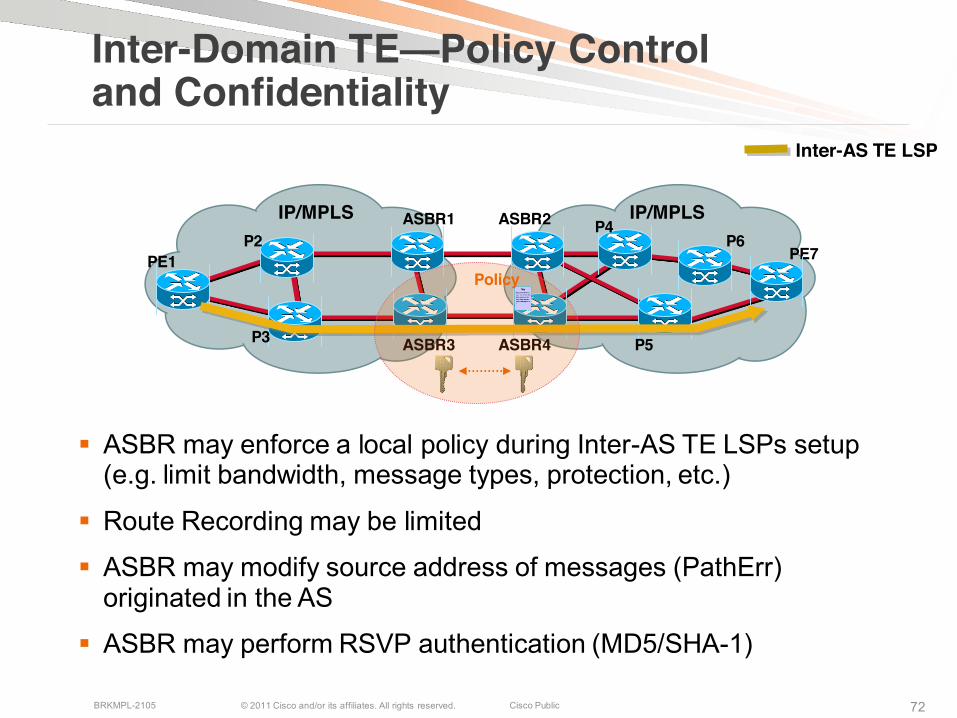
Inter-Domain TE—Policy Control and Confidentiality
ASBR may enforce a local policy during Inter-AS TE LSPs setup (e.g. limit bandwidth, message types, protection, etc.)
Route Recording may be limited
ASBR may modify source address of messages (PathErr) originated in the AS
ASBR may perform RSVP authentication (MD5/SHA-1)
IP/MPLS ASBR1 ASBR2 IP/MPLS
PE1 PE7
ASBR3 ASBR4
P2
P3
P4
P5
P6
Inter-AS TE LSP
Policy

© 2011 Cisco and/or its affiliates. All rights reserved. Cisco PublicBRKMPL-2105 73
Configuring Inter-AS Tunnels (Cisco IOS)
Loose-hop path
List of ASBRsas loose hops
Static route mapping IP traffic to Tunnel1
mpls traffic-eng tunnels!interface Tunnel1ip unnumbered Loopback0
no ip directed-broadcasttunnel destination 172.31.255.5tunnel mode mpls traffic-engtunnel mpls traffic-eng priority 7 7tunnel mpls traffic-eng bandwidth 1000tunnel mpls traffic-eng path-option 10 explicit name LOOSE-PATH
! ip route 172.31.255.5 255.255.255.255 Tunnel1! ip explicit-path name LOOSE-PATH enable
next-address loose 172.24.255.1next-address loose 172.31.255.1
!
© 2011 Cisco and/or its affiliates. All rights reserved. Cisco PublicBRKMPL-2105 74
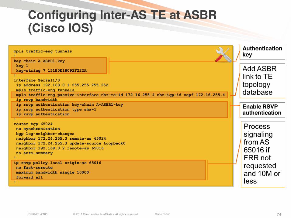
Configuring Inter-AS TE at ASBR (Cisco IOS)
Process signaling from AS 65016 if FRR not requested and 10M or less
Add ASBR link to TE topology database
Authentication key
Enable RSVP authentication
mpls traffic-eng tunnels!key chain A-ASBR1-keykey 1 key-string 7 151E0E18092F222A
!interface Serial1/0ip address 192.168.0.1 255.255.255.252mpls traffic-eng tunnelsmpls traffic-eng passive-interface nbr-te-id 172.16.255.4 nbr-igp-id ospf 172.16.255.4ip rsvp bandwidthip rsvp authentication key-chain A-ASBR1-keyip rsvp authentication type sha-1ip rsvp authentication
!router bgp 65024no synchronizationbgp log-neighbor-changesneighbor 172.24.255.3 remote-as 65024neighbor 172.24.255.3 update-source Loopback0neighbor 192.168.0.2 remote-as 65016no auto-summary
!ip rsvp policy local origin-as 65016no fast-reroutemaximum bandwidth single 10000forward all
!
© 2011 Cisco and/or its affiliates. All rights reserved. Cisco PublicBRKMPL-2105 75
Inter-AS Session Summary

© 2011 Cisco and/or its affiliates. All rights reserved. Cisco PublicBRKMPL-2105 7676
Let’s Summarize
MPLS VPNs model A, B and C have been deployed to support VPNs among Service Providers and within a single Service Provider’s multi-AS networks
MPLS L2 VPNs, L3VPNs (IPv4, IPv6, and multicast VPNs) are supported in multi-domain environment
MPLS TE is also supported in multi-area or multi-AS networks
QoS policies across the ASBRs need to be agreed by the partners
Inter-AS: Extending VPN Boundaries
MPLS Backbone Provider
Customer Carrier-B
Customer Carrier-B
Subscriber A Site1
Subscriber A Site1
Subscriber A Site1 Subscriber A
Site2
Provider-A Provider-BASBR-A ASBR-B
CSC: Hierarchical VPNs

© 2011 Cisco and/or its affiliates. All rights reserved. Cisco PublicBRKMPL-2105 7777
Other related Sessions
BRKMPL-1101 Introduction to MPLS
BRKMPL-2001 Implementation and Utilization of Layer 2 VPN Technologies
BRKMPL-2102 Deploying IP/MPLS VPNs
BRKMPL-2103 Design considerations for enterprise WAN migrating to subscribed MPLS VPN services
BRKMPL-2104 Deploying MPLS Traffic Engineering
BRKMPL-2107 Data Center deployments with MPLS on NX-OS (Nexus 7000)
BRKMPL-2108 Global WAN Redesign Case Study
BRKMPL-3101 Advanced Topics and Future Directions in MPLS
BRKMPL-3102 Designing NGN Networks for Scale, Resiliency and Reliability
77
© 2011 Cisco and/or its affiliates. All rights reserved. Cisco PublicBRKMPL-2105 7878
Other related Sessions
LTRMPL-2104 Implementing MPLS in Service Provider Networks: Introduction
LTRMPL-2105 Implementing MPLS in Service Provider Networks
LTRMPL-2106 Enterprise Network Virtualization using IP and MPLSTechnologies
TECVIR-2003 Enterprise Network Virtualization
TECMPL-3001 Layer 2 Virtual Private Networks - Converged IP/MPLSNetwork
78

© 2011 Cisco and/or its affiliates. All rights reserved. Cisco PublicBRKMPL-2105 79
Meet the Engineer
To make the most of your time at Networkers at Cisco Live 2010, schedule a Face-to-Face Meeting with top Cisco Engineers
Designed to provide a “big picture” perspective as well as “in-depth” technology discussions, these Face-to-Face meetings will provide fascinating dialogue and a wealth ofvaluable insights and ideas
Visit the Meeting Centre reception desk located in the Meeting Centre in World of Solutions
© 2011 Cisco and/or its affiliates. All rights reserved. Cisco PublicBRKMPL-2105 8080
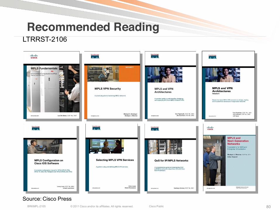
Source: Cisco Press
Recommended ReadingLTRRST-2106

© 2011 Cisco and/or its affiliates. All rights reserved. Cisco PublicBRKMPL-2105 81
Complete Your Online Session Evaluation
Receive 25 Cisco Preferred Access points for each session evaluation you complete.
Give us your feedback and you could win fabulous prizes. Points are calculated on a daily basis. Winners will be notified by email after July 22nd.
Complete your session evaluation online now (open a browser through our wireless network to access our portal) or visit one of the Internet stations throughout the Convention Center.
Don’t forget to activate your Cisco Live and Networkers Virtual account for access to all session materials, communities, and on-demand and live activities throughout the year. Activate your account at any internet station or visit www.ciscolivevirtual.com.

© 2011 Cisco and/or its affiliates. All rights reserved. Cisco PublicBRKMPL-2105 8282
Visit the Cisco Store for Related Titles
http://theciscostores.com
© 2011 Cisco and/or its affiliates. All rights reserved. Cisco PublicBRKMPL-2105 83
Inter-AS mVPNs Option C
© 2011 Cisco and/or its affiliates. All rights reserved. Cisco PublicBRKMPL-2105 85
PE1
PE2
AS #1 AS #2
ASBR1
MDTsP11
ASBR2
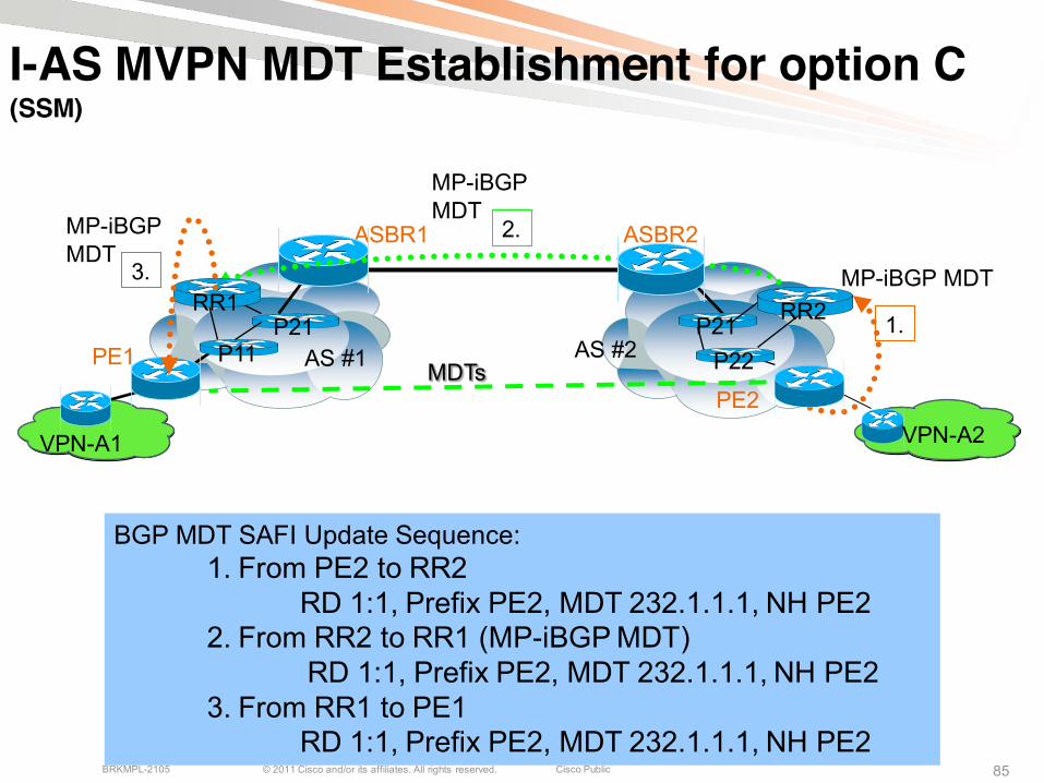
BGP MDT SAFI Update Sequence:1. From PE2 to RR2
RD 1:1, Prefix PE2, MDT 232.1.1.1, NH PE22. From RR2 to RR1 (MP-iBGP MDT)
RD 1:1, Prefix PE2, MDT 232.1.1.1, NH PE23. From RR1 to PE1
RD 1:1, Prefix PE2, MDT 232.1.1.1, NH PE2
VPN-A2
I-AS MVPN MDT Establishment for option C
P21RR1
P21P22
RR2 1.
2.
MP-iBGP MDT
VPN-A1
MP-iBGP MDT3.
MP-iBGP MDT
(SSM)
© 2011 Cisco and/or its affiliates. All rights reserved. Cisco PublicBRKMPL-2105 86
PE1PE2
AS #1 AS #2
ASBR1
MDTsP11
ASBR2
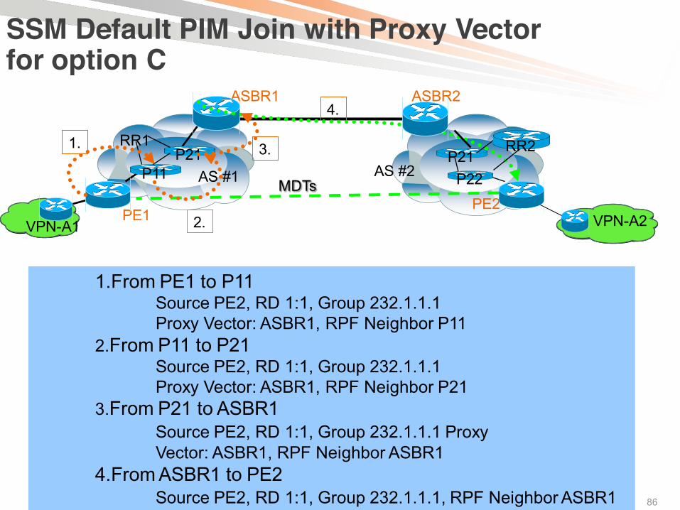
1.From PE1 to P11Source PE2, RD 1:1, Group 232.1.1.1 Proxy Vector: ASBR1, RPF Neighbor P11
2.From P11 to P21Source PE2, RD 1:1, Group 232.1.1.1 Proxy Vector: ASBR1, RPF Neighbor P21
3.From P21 to ASBR1Source PE2, RD 1:1, Group 232.1.1.1 Proxy Vector: ASBR1, RPF Neighbor ASBR1
4.From ASBR1 to PE2Source PE2, RD 1:1, Group 232.1.1.1, RPF Neighbor ASBR1
VPN-A2
P21RR1
P21P22
RR23.
2.VPN-A1
1.
SSM Default PIM Join with Proxy Vector for option C
4.
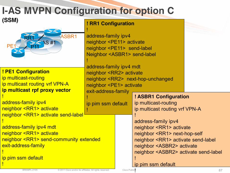
© 2011 Cisco and/or its affiliates. All rights reserved. Cisco PublicBRKMPL-2105 87
PE1AS #1 AS #2
ASBR1
I-AS MVPN Configuration for option C
P11
ASBR2
! PE1 Configurationip multicast-routingip multicast routing vrf VPN-Aip multicast rpf proxy vector!address-family ipv4neighbor <RR1> activateneighbor <RR1> activate send-label!address-family ipv4 mdtneighbor <RR1> activateneighbor <RR1> send-community extendedexit-address-family!ip pim ssm default!
RR1 RR2
! RR1 Configuration!address-family ipv4neighbor <PE11> activateneighbor <PE11> send-labelNeighbor <ASBR1> send-label!address-family ipv4 mdtneighbor <RR2> activateneighbor <RR2> next-hop-unchanged neighbor <PE1> activateexit-address-family!ip pim ssm default!
! ASBR1 Configurationip multicast-routingip multicast routing vrf VPN-A!address-family ipv4neighbor <RR1> activateneighbor <RR1> next-hop-selfneighbor <RR1> activate send-labelneighbor <ASBR2> activateneighbor <ASBR2> activate send-label!ip pim ssm default!
(SSM)