Embed Size (px)
Citation preview

1
1Introduction to Informix Dynamic Server
In this Chapter
Understanding the server’s architecture
Defi nition of key terms
By virtue of the fact that you’re reading this book, either you are new to Informix Dynamic Server (IDS) or you’re migrating from an earlier version of the data server
and want to know how to use and manage the new functionality available to you. In either case, you’re in for a good learning experience. There’s a lot involved in understanding how this database server operates and how to make it perform in your particular environment.
The intent of this book is to make the learning process easier by distilling for you what you really need to know to confi gure, run, and tune a database environment using Informix Dynamic Server. Although at fi rst glance IDS may seem similar to other data server products, this server is in fact unlike any other. It won’t take you long to see that IDS is far more advanced technologically as well as more stable, easier to administer, and more robust than competing servers.
IDS 11, the focus of this book, is both very much like earlier versions of the product and also radically different. Version 11 incorporates signifi cant new technology built on a completely modifi ed server architecture introduced with IDS 9.1. Yet for all the changes, the server is still managed and operates as before—in many cases, it’s even easier to administer!
Today’s IDS is not a “regular” data server as many people might classify it; rather, it is an “object-relational” server. IDS includes high-performance core server technology developed in the early 1990s to take advantage of emerging symmetric multiprocessing (SMP) and massively parallel processing (MPP) technology, and it has been continually

2
Chapter 1: Introduction to Informix Dynamic Server
enhanced since then. The biggest enhancement was the addition of object-oriented database functionality throughout the server in 1995. This feature completely changed how DBAs and application developers can and should model and use data within their databases and applications. IDS now offers many more tools and options than the standard, relational-only data servers.
This chapter introduces the architecture of the data server and its three main components. We’ll also go over some key terminology that is either unique to Informix Dynamic Server or has a new or different meaning when used with this product. By the end of the chapter, you should understand why the product has the name it does, what a thread is, and what the fundamental components of the data server are.
This book assumes you have some level of familiarity with the SQL language and with standard relational and object-oriented database concepts. However, we won’t engage in a heavy bits-and-bytes discussion. If you need that level of detail, consult the documentation accompanying your distribution of the software or visit IBM’s Informix Web site.
What Is Informix Dynamic Server?
Informix Dynamic Server is a data server—or, to use a marketing buzzword, an object- relational database management system (ORDBMS). The server can work both with “standard” (or relational) data types, such as character and numeric values, and with object-oriented data types. This new technology is an extension to the ability the server has had for years to store nonnumeric or non-ASCII data in binary large objects (BLOBs). Today, IDS can do more than just write the binary stream to disk as it does with simple BLOBs. Using the appropriate functions, you can not only store the data “object” but also manipulate, search, alter, and correlate it; you can execute any operation against it that makes sense for the data and is provided by the function. This new functionality and associated data type support is commonly referred to as extensibility and extensible data types.
In general terms, though, the server’s job is to provide an environment whereby data can be stored, retrieved, changed, and deleted in such a way that data itself is not lost, compromised, or modifi ed outside the rules established by the data server or the data-base administrator. IDS contains both logical and physical mechanisms to accomplish these tasks.
From a logical point of view, IDS provides the ability to set rules and conditions governing not only the acceptable range of values for a column in a table but also where a row will be stored on disk. You can specify the conditions that must exist for data elements in the row to be modifi ed or deleted. You can set up procedures to be invoked automatically and execute specifi c database actions to enforce still other rules when data in a table or column is added, modifi ed, or deleted.
3
From a physical point of view, IDS keeps a series of logs that record changes made to data as they occur and provides a locking mechanism you can use to ensure that data requested by one user session can’t be changed or deleted by another. The data server can create copies, in whole or in part, of database environments, either within the same physical server or on a separate server, to minimize the impact of a physical server failure, to distribute/collect data between database environments, to enable load balancing, or to provide continuous availability of data services. Last, IDS provides the ability to create backups of database environments that can be used to restore some or all of a database environment should a mechanical failure or user error occur. You can even confi gure the restore to stop at a specifi c point in time so the user error doesn’t recur, permitting full data recovery up to the moment the operation took place. Other recently added functionality enables restoring a backup created on one physical server to another physical server even if the second server isn’t using the same operating system (O/S).
Built on the widely heralded Dynamic Scalable Architecture (DSA), the IDS data server was designed to run on, and take advantage of, today’s computer systems with multiple physical CPUs and larger memory stores. In fact, fi eld studies have shown that as more physical resources (e.g., CPUs) are added to the system, IDS performance increases linearly.
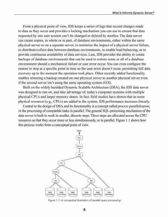
Central to the design of DSA and its functionality is a concept called process parallelization, or the processing of compatible tasks in parallel. The general SQL-processing mechanism of the data server is built to work in smaller, discrete steps. These steps are allocated across the CPU resources so that they occur more or less simultaneously, or in parallel. Figure 1.1 shows how this process works from a conceptual point of view.
Figure 1.1: A conceptual illustration of parallel query processing
What Is Informix Dynamic Server ?

4
Chapter 1: Introduction to Informix Dynamic Server
The fi gure illustrates how a query might be executed in parallel. At the beginning of the process, a series of disk reads occurs. The results from this step, and from every other in the process, are passed in real time up the processing ladder of functional operations. At each level of the process, there are fewer rows to work with, and the results generated by each operation are joined with the results of the other operations at the same level. Eventually, the data server returns the fi nal result to the application in what amounts to signifi cantly less time than if the query process executed the steps serially, waiting for each step to be completed before beginning the next step, and with larger amounts of data.
In addition to processing SQL operations more quickly, IDS executes most administrative functions—such as building indexes, updating database statistical information, and checking and potentially repairing the database system after a failure—in parallel as well. This type of functionality brings with it the responsibility to monitor and tune for it. As the data server administrator, you must set the resource limitations within which parallel processing of queries and other activities must occur. Look for coverage of this topic and other advanced tuning operations in the companion to this book, Administering Informix Dynamic Server, Advanced Topics.
Another key feature of IDS’s architecture is the ability of the server to allocate and release physical server resources dynamically when necessary. For example, you might confi gure an IDS database environment to use x MB of system RAM, y data locks, and so on when the database environment starts. If the data processing load spikes, IDS will try to secure more system resources (e.g., memory) to handle the increased load rather than fail due to insuffi cient resources. Knowing that IDS’s attempt to obtain additional system resources is not unbounded, you can set explicit boundaries to the resources that the data-base environment can take from the system.
Finally, you can adjust most IDS database environment confi guration parameters while the database environment is online and processing user transactions. IBM continues to enhance this functionality with every release of the data server, and it is nearly complete now. IDS’s ability to intelligently self-manage required resources and be administered without interruption accounts for the word “dynamic” in the product’s name.
With the addition of object-oriented technology, IDS delivers proven functionality that effi ciently integrates new and complex data types directly into the database. It handles time-series, spatial, geodetic, Extensible Markup Language (XML), video, image, and other user-defi ned data side by side with traditional legacy data to meet today’s most rigorous data and business demands. IDS is also a development-neutral environment that supports a comprehensive array of application development tools for rapid deployment of applications under Linux, Unix, Apple Mac OS X, and Microsoft Windows operating environments.
5
The Informix Dynamic Server Model
Data server architecture is a signifi cant differentiator and contributor to IDS’s performance, scalability, and ability to support new data types and processing requirements. Nearly all data servers available today use an older technological design that requires each database operation for an individual user (e.g., read, sort, write, communications tasks) to invoke a separate operating system process. This architecture worked well when database sizes and user counts were relatively small. Today, these types of servers spawn many hundreds, even thousands, of individual processes that the operating system must create, queue, schedule, manage/control, and then terminate when they’re no longer needed. Given that, generally speaking, any individual system CPU can work on only one thing at a time—and that the operating system must work on each process before returning to the top of the queue—this data server architecture creates an environment in which individual database operations must wait for one or more passes through the queue to complete their task. Scalability with this type of architecture has nothing to do with the software; it depends entirely on the speed of the processor—how fast it can work through the queue before it starts over again.
As I mentioned in the previous section, the Dynamic Scalable Architecture on which Informix Dynamic Server is built was designed to work with multiple physical CPUs and larger memory stores to create an operating environment with greater data server performance and improved stability. The DSA includes built-in multithreading and parallel-processing capabilities, dynamic and self-tuning shared memory components, and intelligent logical data storage capabilities, supporting the most effi cient use of all available system resources. Three major functional components make up the architectural model for Informix Dynamic Server:
● The processor component
● The shared memory component
● The disk component
Let’s look at each of these pieces individually.
The Processor Component
IDS provides the unique ability to scale the database environment by employing a dynamically confi gurable pool of data server processes called virtual processors (VPs). (Look for a in-depth explanation of exactly how VPs work in Administering Informix Dynamic Server, Advanced Topics.) As you saw in Figure 1.1, IDS takes a database operation such as a sorted data query and segments it into task-oriented subtasks
The Informix Dynamic Server Model

6
Chapter 1: Introduction to Informix Dynamic Server
(data scan, join, group, sort) for rapid processing by virtual processors that specialize in each type of subtask. VPs mimic the functionality of the hardware CPUs in that they schedule and manage user requests using multiple, concurrent threads. Figure 1.2 illustrates how IDS’s pool of virtual processors operate.
Figure 1.2: IDS virtual processor pool

7
A thread represents a discrete task within a data server process. Multiple threads can execute simultaneously, in parallel, across the pool of virtual processors. Unlike a CPU process-based (or single-threaded) engine, which leaves each task on the system CPU for its given unit of time (even if no work can be done, thus wasting processing time), IDS’s virtual processors are multithreaded. As a consequence, when a thread either is waiting for a resource or has completed its task, a thread switch occurs and the virtual processor immediately begins work on another thread. As a result, precious CPU processing power is used to satisfy as many user requests as possible in the given amount of time. Figure 1.3 illustrates this capability, known as fan-in parallelism.
Figure 1.3: Fan-in parallelism
The Informix Dynamic Server Model

8
Chapter 1: Introduction to Informix Dynamic Server
Not only can one virtual processor respond to multiple user requests in any given unit of time, as this fi gure illustrates, but one user request also can be distributed across multiple virtual processors. For example, with a processing-intensive request such as a multitable join, the data server divides the task into multiple subtasks and then spreads these subtasks across all available virtual processors. With the ability to distribute tasks, the request is completed more quickly. Figure 1.4 illustrates this capability, referred to as fan-out parallelism.
Figure 1.4: Fan-out parallelism

9
The net effect of IDS’s two types of parallelism is more work being accomplished more quickly than with single-threaded architectures. In other words, the data server is faster.
Because threads aren’t statically assigned to virtual processors, load balancing occurs dynamically within IDS. Outstanding requests are serviced by the fi rst available virtual processor, balancing the workload across all available resources. For effi cient execution and versatile tuning, you can group VPs into classes, each optimized for a particular function. Figure 1.5 illustrates this capability, showing VPs optimized for CPU operations, disk I/O, communications, administrative, and other tasks.
The design of IDS’s VPs also includes administrative access, resulting in the ability to easily look at and analyze the activities requested by users and the data server. With single-threaded servers, each operation is a separate and independent operating system process with its own data stack, instruction cache, and other O/S overhead, making it diffi cult to build a comprehensive view of what’s happening inside the data server. In contrast, IDS’s onstat and oncheck administrative utilities gather information from the
Figure 1.5: IDS virtual processors optimized for specifi c functions
The Informix Dynamic Server Model

10
Chapter 1: Introduction to Informix Dynamic Server
database environment’s shared resources and can easily display who is doing what and how much of an impact it’s having on the system.
You can confi gure the database environment with the appropriate number of VPs in each class to handle the expected workload for that environment. You can even defi ne custom VPs to be used only for specifi c functions. Called user-defi ned virtual processors (UDVPs), these VPs have the same processing power as the database environment’s core CPU VPs but are isolated from operating on core functionality. With this separation, if the user function that a UDVP is executing “misbehaves,” the function can’t intentionally or unintentionally cause an abnormal shutdown.
If necessary, you can also adjust the number and type of VPs while the database environment is online, without interrupting database operations—for example, to handle different load mixes or occasional periods of heavy activity. In Linux, Mac OS X, and Unix systems, the use of multithreaded virtual processors signifi cantly reduces the number of O/S processes, requiring less context switching as a result. Windows systems implement VPs as threads to take advantage of the inherent multithreading capability of the operating system. Because IDS includes its own threading capability for servicing client requests, it requires fewer Windows threads, reducing the system thread-scheduling overhead and providing better throughput.
In making full use of the hardware processing cycles, IDS needs less hardware power to achieve performance comparable to or better than that of other database servers. In fact, real-world tests and customer experiences indicate IDS needs only 25 percent to 40 percent of the hardware resources to meet or exceed the performance characteristics of single-threaded or process-based data servers. This effi ciency means your business can save money on hardware purchases as well as on ongoing maintenance.
The Shared Memory Component
With the consolidation of tasks and processes into VPs, all the memory used by the data server is consolidated as well. This large, single block of shared memory enables IDS to transfer data easily among the VPs. It also lets other user connections determine whether the data they need has already been queried by another user and can be used for their request, rather than having to go out to disk to get it. The memory inside this block is used and reused as needed to process user connections. When a user session terminates, the thread-specifi c memory for the session is freed and reused by another session.
If the database environment requires more memory to process its workload, the data server allocates additional blocks of memory dynamically from the operating system until it reaches the limit set during the database environment’s confi guration. When the

11
need for the additional memory is gone, the additional segments of memory are released. You can make similar changes manually while the database environment is running. This ability to dynamically add and release memory helps eliminate down time to retune the environment as the workload increases and decreases. Released memory is returned to the general O/S pool for use by other processes, further enhancing the effi ciency of the server’s use of shared memory.
Four areas, or portions, make up Informix Dynamic Server’s shared memory component:
● The resident portion
● The virtual portion
● The message portion
● The virtual-extension portion
When you start a database environment, at least two, and possibly all four, portions are allocated, according to the shared memory and connection confi guration parameters set during the initialization process and the server functionality used. Chapter 4 provides more information about the shared memory confi guration parameters. The following sections briefl y describe the portions of the IDS shared memory component.
The Resident Portion
The resident portion of IDS’s shared memory contains, among other things, general database environment information and the buffer pool that holds data operated on by user or database environment activities. Several system-wide structures are maintained in this part of shared memory. The logical and physical log buffer caches are here, as well as the system tables, which maintain information about chunks, dbspaces, locks, user connections, transactions, and mirrors. The system tables are accessible to queries through the System Monitoring Interface (which you’ll learn about in Chapter 4). If you’ve enabled High- Availability Data Replication (HDR), the replication buffer is also stored in the resident portion of shared memory. You’ll fi nd more details on HDR as well as Enterprise Replication in Administering Informix Dynamic Server, Advanced Topics.
The biggest part of the resident portion consists of the data buffers used to store queried or modifi ed data for user applications. Depending on the types of operations executed, these buffers can help eliminate a lot of disk I/O. When users request data, the data server fi rst tries to locate the data in the buffer pool to avoid unnecessary disk I/Os. Depending on the characteristics of the database workload, increasing the buffer pool size can signifi cantly reduce the number of disk accesses, which in turn can considerably improve performance, particularly for online transaction processing (OLTP) applications.
The Informix Dynamic Server Model
12
Chapter 1: Introduction to Informix Dynamic Server
IDS holds frequently used table or index data in the buffer pool using a scorecard system. As each element is used, its score increases. Part of the buffer system holds the high-score elements, while the remainder holds less frequently used data. This segmentation of high- and low-use data is completely transparent to the application, which experiences in-memory response times regardless of which part of the buffer pool contains the requested element. As data elements are used less often, they are migrated from the high-use to the low-use portion. Data buffers in this area are fl ushed and reused through a fi rst-in, fi rst-out (FIFO) process.
Before IDS 10, all buffers were the same size: either 2 KB or 4 KB, depending on the operating system. The buffers were the same size as the “pages” on disk, permitting a buffer to cache one disk page. IDS 10 provided the ability to defi ne regular data dbspaces with varying page sizes in multiples of the default page size up to 16 KB in size. To continue caching one page to a buffer, the data server will allocate a buffer pool for each page size in the resident portion of shared memory if you create dbspaces with different page sizes. Only one set of buffers will exist for each page size, though, so if you create three dbspaces using an 8 KB page size, they will share one 8 KB buffer pool.
The BUFFERPOOL, BUFFERS, LRU (Least Recently Used), and other confi guration parameters determine the number of buffers and how they are allocated. With the addition of recovery time objectives, the data server itself can manage these parameters for you, eliminating work you used to do in earlier IDS versions.
Because the resident portion holds end-user data, it will always exist in every IDS database environment.
The Virtual Portion
The virtual portion of shared memory contains thread stacks, or thread-specifi c instructions, for the processing of each thread. Along with the thread stacks, IDS maintains pointers to the data that the thread is using in the buffer pool of the resident portion. The virtual portion of shared memory contains pools of memory for the following tasks and items:
● Sorting data
● Caching database dictionaries that hold information about the tables and indexes in the environment’s databases
● Caches from user-defi ned routines
● The big buffer pools for the asynchronous I/O (AIO) VPs
● Storage of compiled versions of stored procedures
13
● The “global” pool to handle network protocol–based application communications
● Some memory-based tables used to monitor various aspects of the environment
The virtual portion also holds cached disk-access plans for the IDS cost-based optimizer. In most OLTP environments, the same SQL operations are executed throughout the processing day, albeit with slightly different variable conditions (e.g., customer number, invoice number). Each time an SQL operation is executed, the data server optimizer must determine the fastest way to access the data. Obviously, if the data is already cached in the buffer system, it is retrieved from there; if it is not, disk access is required. When this occurs, the optimizer has to decide on the quickest way to get the requested data. It needs to evaluate whether an index exists that points directly to the requested data or whether the data has been intelligently partitioned on disk, restricting the potential number of dbspaces to look through. When joining data from several tables, the optimizer evaluates which table will provide the data the others will join to, and so on. Although not really noticeable to users, these tasks take time to execute and affect response time.
Informix Dynamic Server provides a caching mechanism whereby data I/O plans can be stored for reuse by subsequent executions of the same operation. Called, appropriately enough, the SQL statement cache, this allocation of memory stores the SQL statement and the optimizer’s determination of the fastest way to execute the operation. You can confi gure the size of this cache as well as when an individual SQL operation is cached (e.g., the fi rst time, after two executions). To prevent fi lling the cache with single-use operations, most confi gurations cache an operation after it has been executed three or more times. You can also fl ush the cache so the query plans are refreshed if needed while processing continues. You would take this step after execution of the update statistics commands, for example.
Another interesting component of the virtual portion is the big buffer pool. Earlier versions of the data server had two types of buffers: regular and big. The regular buffers acted much as the buffers stored in the resident portion of IDS do now, but for every 100 regular buffers, earlier versions of the data server would allocate a single big buffer. The big buffer was eight data pages in size and was used to buffer large sequential reads or large writes, such as simple BLOB writes.
Today, a big buffer is allocated for each AIO VP. The buffer’s size varies by operating system, but at 32 pages it is signifi cantly larger than in earlier IDS versions. This larger size enables the big buffer to more effi ciently service the sorting of writes during a check-point or the reading in of larger amounts of data for complicated analytical queries. Once data is read into the big buffer, it is reallocated to the regular buffer pool in the resident portion of shared memory for actual use. Because of the potential size of a simple BLOB, IDS handles the reading or writing of this type of object through the big buffer rather than
The Informix Dynamic Server Model
14
Chapter 1: Introduction to Informix Dynamic Server
through the regular buffer pool. (We’ll review some of this terminology, including data page, checkpoint, and BLOB, later in the chapter.)
The virtual portion of shared memory expands and contracts as needed depending on the amount of memory required to accomplish its tasks—this is the dynamic portion of shared memory I spoke of earlier. You set the initial size of the virtual portion using the SHMVIRTSIZE confi guration parameter. The SHMADD parameter controls the size of the additional segments added to this portion of shared memory. A third parameter, SHMTOTAL, controls the total amount of shared memory the database environment can allocate (which includes both portions).
The virtual portion of shared memory will always exist in every IDS database environment.
The Message Portion
Unlike the two portions of shared memory we’ve just covered, the message portion is created only if a co-resident application connection protocol is activated for the database environment. The message portion contains the buffers for exchanging information to and from local client applications running on the same physical server and connecting to the database environment via a shared memory connection.
You must defi ne every connection protocol you want to use to connect to databases managed by IDS. If you’ve enabled a shared memory connection protocol, local appli cations connecting to the database server through this protocol leave messages requesting data or other actions and retrieve data or confi rmation messages from previous requests in the message portion of IDS shared memory. This same type of communications process occurs for network protocol–based application connections, although not through this part of shared memory. (I’ll explain this point further in conjunction with the NETTYPE confi guration parameter in Chapter 4. Briefl y, with connections based on network protocols, the listener thread passes messages and data to and from the global pool in the virtual portion of shared memory.)
The Virtual-Extension Portion
The virtual-extension portion of shared memory performs two functions. First, if a DataBlade or a user-defi ned routine (UDR) is executing against a UDVP, the data server isolates the data for these functions from the rest of the buffer pools. In doing so, it protects the main pools from potential corruption should the UDR misbehave and either execute a command detrimental to the health of the database environment or just die and corrupt the buffer structure. IDS creates and maintains the buffer pools to cache data for these functions in the virtual-extension portion of shared memory.

15
As I noted previously, if the virtual portion needs to expand, it tries to dynamically request additional memory from the operating system. Additional memory for the virtual-extension portion is created in and managed through the virtual portion, and it, too, dynamically expands and contracts as needed.
Depending on the current workload and functionality used, the virtual-extension portion may or may not exist in an IDS environment.
The Disk Component
In most installations of Informix Dynamic Server on Unix and similar operating systems, the data server itself, rather than the O/S, manages all interactions between the disks storing data and the database environment. The data storage elements are usually built using disk partitions devoid of a fi le system, known as raw disk space.
By their very nature, storage elements created in Unix raw space are guaranteed to be contiguous. The data server reads from and writes to these disks through Direct Memory Access (DMA) calls and Raw Sequential Access Method (RSAM) mechanisms. Because RSAM mechanisms are so much better suited to database-oriented disk activity than the Unix fi le system and its series of write buffers, signifi cantly better performance has been achieved by letting the data server, rather than the operating system, manage database disk operations. Performance improves even more if the O/S supports kernel asynchronous I/O (KAIO), or the ability to process several I/O operations at the same time without having to wait for a response back from the I/O subsystem.
Database storage elements can also be created using regular O/S fi le system fi les, space referred to as cooked space. Using cooked space does not guarantee, however, that the disk blocks used to create the storage element(s) will be contiguous; in fact, you can be assured they will not be. This characteristic does have an impact on the overall performance of disk-oriented activities.
Some operating systems, such as Windows, use unbuffered and noncached I/O to communicate with cooked disk spaces. As a result, although you can use raw disk space in a Windows environment, doing so provides no signifi cant performance benefi t. With IDS 11, support for using O/S-based unbuffered I/O is expanding to other operating systems. For those environments that need the ability to manage all aspects of disk use with standard fi le system tools, this functionality (if supported on your port of the data server) may be able to provide near raw-disk speed with fl at-fi le-based chunks and dbspaces.
Truth be told, this functionality is not exclusive to IDS. Although some data servers support only cooked storage elements created in fi le systems, others support both raw and cooked. Where IDS shines is in its ability to intelligently distribute data based on rules
The Informix Dynamic Server Model

16
Chapter 1: Introduction to Informix Dynamic Server
within the disk subsystem. IDS supports a number of partitioning schemes to improve the ability to quickly isolate and retrieve or modify data. This same functionality also permits much higher data availability, concurrency, and the easy management of older, less-used data (sometimes called data life-cycle management).
Several physical and logical divisions occur with disk drives to actually make up this component of the engine. To put these elements in their proper context, I need to introduce some additional terms. The next section covers these key words and some others you need to know to understand the data server’s disk component. Chapter 3 provides an in-depth continuation of the discussion of this component.
Key Terminology
Throughout this book, I’ll be using some key terms and phrases that either are unique to Informix Dynamic Server or have new or different meanings as far as this product is concerned. Before we go too much further, let me defi ne some of the more common keywords I haven’t used yet and describe how they apply to IDS. As you read the book, it might appear as though many of these keywords are, or could be, used interchangeably. This is not the case. To avoid ambiguity in terms of scope or precision, I will be careful to use the proper term in the proper context. I will also refrain from using computational slang that might be misleading, especially to those who are new to using this product.
Throughout the book, I’ll be referring to “instances” and occasionally to a “data server.” A data server is the compiled source code that you purchased a license for and which is loaded on your physical server; it is Informix Dynamic Server. This server contains all the utilities and programs to create, secure, administer, and connect database services to end-user applications. In terms of administration and tuning, you do very little, if anything, with the data server itself. With proper fi le system management and environmental variable handling, it is possible and quite common to have more than one version of the IDS data server installed on a physical server. You’ll learn more about this topic in Chapter 3.
An instance, on the other hand, is a unique working or run-time environment that you create to host a collection of databases to which end users may or may not have access, depending on the instance rules or database-level security enabled. Up to this point in the book, I’ve been using the term “database environment” in place of the word “instance.” Instances, and databases for that matter, are tuned for performance and throughput. Any changes you make to the general operating environment of a database are made at the instance level. The data server provides the operational code and maintains the general overhead as defi ned by the instance’s confi guration parameters.

17
A single physical server, with one version of the data server installed, can support multiple instances. Each instance has its own unique set of confi guration parameters, memory space, and disk allocation; it does not share these things with other instances on the same physical server.
Physical Elements
To better understand how the physical elements combine to create logical structures, look at Figure 1.6. In this diagram, solid lines represent physical elements, while dashed lines portray logical structures.
The basic physical element of an instance is called a data page, or simply a page. A data page has a fi xed size called the page size; the page size is the smallest amount of data read or written from or to disk. As I mentioned previously, every port of IDS has an initial or default page size, which will be either 2 KB or 4 KB depending on the operating system. Most of IDS’s monitoring and reporting utilities that display disk space usage list the space in pages rather than in kilobytes or megabytes. When converting to “real” numbers, you can simply multiply the number of pages by 2 (or 4, 6, 8, 12, or 16) to get an approximate size in megabytes.
Figure 1.6: Physical and logical structures in an IDS instance
Key Terminology
18
Chapter 1: Introduction to Informix Dynamic Server
While data is read and written in pages, the smallest piece of disk you can work with from an administrative point of view is called a chunk. From a physical standpoint, a chunk is usually an entire disk partition, although it can be a smaller but logically contiguous portion of a single disk partition (as I’ll explain in Chapter 5). If you’re using cooked space to create storage locations, a chunk is an individual fl at fi le. From a logical point of view, a chunk is a collection of data pages and is the basic building block for creating, or adding to, dbspaces.
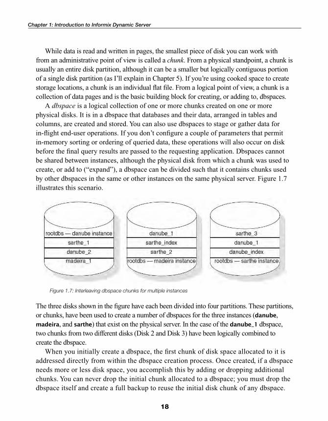
A dbspace is a logical collection of one or more chunks created on one or more physical disks. It is in a dbspace that databases and their data, arranged in tables and columns, are created and stored. You can also use dbspaces to stage or gather data for in-fl ight end-user operations. If you don’t confi gure a couple of parameters that permit in-memory sorting or ordering of queried data, these operations will also occur on disk before the fi nal query results are passed to the requesting application. Dbspaces cannot be shared between instances, although the physical disk from which a chunk was used to create, or add to (“expand”), a dbspace can be divided such that it contains chunks used by other dbspaces in the same or other instances on the same physical server. Figure 1.7 illustrates this scenario.
The three disks shown in the fi gure have each been divided into four partitions. These partitions, or chunks, have been used to create a number of dbspaces for the three instances (danube, madeira, and sarthe) that exist on the physical server. In the case of the danube_1 dbspace, two chunks from two different disks (Disk 2 and Disk 3) have been logically combined to create the dbspace.
When you initially create a dbspace, the fi rst chunk of disk space allocated to it is addressed directly from within the dbspace creation process. Once created, if a dbspace needs more or less disk space, you accomplish this by adding or dropping additional chunks. You can never drop the initial chunk allocated to a dbspace; you must drop the dbspace itself and create a full backup to reuse the initial disk chunk of any dbspace.
Figure 1.7: Interleaving dbspace chunks for multiple instances

19
So, an instance is a completely standalone data-processing environment with a collection of dbspaces containing databases that store data in a relational order of tables and columns, temporary work areas, and precompiled functions (called stored procedures or user-defi ned routines) that can be called either by an end user or by the instance itself to manipulate data. As you’ll see in the chapters that follow, an instance has its own logical name by which it is known on the network and has its own confi guration parameters that determine, to a certain degree, how the instance will operate.
Instance Elements
A couple of structures inside an instance are critical to the overall health and stability of the instance itself. The rootdbs is the core dbspace for the instance. This dbspace contains all the instance-wide overhead information and will be used as a last resort for some operations if suffi cient space is not available in other instance dbspaces. Corruption in the rootdbs renders the entire instance inaccessible; the same is true for the physical and logical logs.
The physical log holds the “before image” of data prior to it’s being changed. If the instance needs to reverse a change that an application has made to data, it uses the information stored in this log. The logical log holds some before images of the data, but it also records the changes made to the data and whether those changes were actually written to disk. Without these two types of logs, the instance cannot function.
Database Terms
You probably already have a good idea of what a relational database is and how one is structured from a conceptual point of view. You understand that data elements are stored in columns and that a series of one or more columns creates a row. Rows of data are grouped together in tables, and important, or key, columns can be used to create fast access paths into the data called indexes.
In addition to the character and numeric data types common to all relational databases, you also have the capability of using “nonstandard,” or what in the IDS world are called extensible, data types. With these types, you can now create, manipulate, and analyze nonnumeric or non-ASCII data directly within the data server and its instances. You can create data types of your own design to meet your own unique applications or needs. With IDS’s object orientation, elements from as small as a column to as large as a table can have various elements of inheritance and other functionality attached to them that are not possible in purely relational data servers. With this capability, you can analyze traditional data elements in new and exciting ways that are not easily accomplished under the restrictions of the relational database model.
Key Terminology

20
Chapter 1: Introduction to Informix Dynamic Server
IDS also has special, proprietary structures called binary large objects, or BLOBs. There are two types of BLOBs: simple and smart. Simple BLOBs are black-box data types as far as the data server is concerned. At a table level, references to where a BLOB is stored on disk exist, but there is no inherent defi nition of, or interface into, the BLOB other than the descriptive information you choose to add in regular character columns for a row of data. Smart BLOBs, on the other hand, consist of data types the data server can intelligently manipulate using functionality that has been added to the instance. This additional functionality could come from a DataBlade, a Bladelet, or your own UDRs. (We’ll discuss DataBlades, Bladelets, and the object-oriented data types in much greater detail in the next chapter.)
The advantage of BLOBs is that a large amount of contiguous information or nonstandard data can be stored together rather than being broken up into fi xed-length amounts, as required with standard data types. You can handle BLOBs differently than regular data types when storing them on disk as well. You can create one or more specially tuned dbspaces, called BLOBspaces, to store BLOBs. As with BLOBs, there are two kinds of BLOBspaces: simple BLOBspaces (usually just called BLOBspaces) and smart BLOB-spaces. BLOBspaces are not too different from standard dbspaces, particularly now that you can create standard dbspaces with varying page sizes. BLOBspaces were the fi rst to have this page size variability so that BLOBs could be stored on a single BLOB-page. Smart BLOBspaces differ slightly in that while the smart BLOBs they contain are referenced from the base table, the actual storage and retrieval of smart BLOB data is managed through metadata created and stored within the smart BLOBspace. Chapter 5 provides more information about creating both types of BLOBspaces.
The BLOB data itself, whether simple or smart, generally falls into one of two orientations: text or true binary. Text-oriented BLOBs, as their name implies, are mainly character in nature and are represented as documents in some form. I’ve worked with instances where word-processing documents, with all their control codes, were stored as a single row in a table in a column defi ned as a simple BLOB data type. When a row was selected out of the table, the BLOB column was passed as a parameter to a shell script that invoked the word-processing program. To save the document inside the database, the user invoked a macro that passed the document back to the database for storage using an insert or update SQL command.
You can use the same type of interaction with BLOBs that are binary in nature. A binary BLOB is any other piece of nonstandard data to be stored in the database. This data could be a digitized sound sample, digitized images or video, or anything else digitally created outside the database environment that you need to store. As with the word-processing documents I stored as BLOBs, the application would be completely responsible for receiving and manipulating the binary BLOB data stream as it comes out of the table.

21
As I discussed earlier, tables to store data within an IDS instance reside in dbspaces created with chunks that can have two different disk formats: raw or cooked. Raw space refers to disk partitions that have no fi le system on them, while cooked space does have a standard fi le system in place.
A grouping of a table’s rows is called a table extent, commonly referred to as an extent. Based on the number of rows you anticipate a table will need to hold, you can create an extent large enough to hold all those rows in a logically contiguous state. Due to the very nature of cooked fi le space, however, the rows won’t be physically contiguous as happens when you create a table using raw space. If the table extent fi lls up with data and more disk space is required, the table will add another extent, although it may not be contiguous to the initial extent if there are other tables in the same dbspace. Figure 1.8 shows an example of creating additional extents that are not contiguous but are separated by extents of other tables, a process known as interleaving. (You’ll learn more about table extents and interleaving in Chapter 3.)
Although you will never have truly contiguous extents with cooked space, too many inter-leaved extents will cause a thrashing condition to occur when reading data. In Chapter 8, you’ll learn about a command you can run to show how much interleaving is occurring in a dbspace so you can take steps to reduce it if necessary.
When a table is created in Informix Dynamic Server, it can either reside completely in one dbspace or be split up into different dbspaces, depending on rules you set up. This
Figure 1.8: Interleaving table extents
Key Terminology
22
Chapter 1: Introduction to Informix Dynamic Server
process is called fragmenting or partitioning a table. Tables aren’t the only objects that can be partitioned; indexes have partitioning options as well. Intelligently partitioning table and index data can result in tremendous performance increases as the data server’s ability to parallelize operations is maximized. Chapter 5 explains the process of partitioning tables and indexes in much greater detail.
Types of Database Environments
Database environments themselves fall into two broad categories to which I will refer frequently in this book. Online transaction processing, or OLTP, environments are usually very disk read and write intensive. They typically serve many users executing limited and focused database actions and (depending on the processing environment) requiring almost instantaneous response times. Most general business workfl ow applications are OLTP oriented—such as order taking and processing, payroll modifi cations, and shipping and receiving functions. IDS is particularly well suited to the OLTP processing environment.
Online analytical processing (OLAP) or decision support systems (DSS) environments are characterized by fewer total users but much larger data stores, more complex queries covering longer time periods, and less stringent response requirements. Another common term is a data warehouse, or in smaller, more focused data sets, a data mart. Transitional repositories, where data is staged and somewhat condensed, are called operational data stores (ODSs). Although IDS’s true strength lies in OLTP processing, many customers use IDS for data warehousing and other analytical repositories due to its storage scalability, extensive data typing, hardware effi ciency, performance, and attractive administrative costs.
Transactions
Sometimes, several database actions have to occur as a matched set, or else all actions must be reversed. Such a group of actions is called a transaction. A commonly used example of a transaction is the transfer of money in a bank. Say you need to transfer money from your savings account to your checking account. For the transfer to be com-pleted successfully, the sum of money to be transferred needs to be both debited from the balance of the savings account and credited to the checking account. These two actions balance the transaction fi nancially. Should either the debit or the credit action fail, both actions must be reversed and the account balances restored to their original values.
When I introduced the concept of the rootdbs, I noted that the IDS data server tracks changes made to data as part of a transaction using two components it saves to disk: the physical and logical logs. The physical log stores the original values of the data that is about to change. In transactions in which data is modifi ed or deleted, the data server
23
copies this information, along with the changes made, to the current logical log on a regular basis. Using our banking example, when both changes of the transaction are completed, the transaction is said to be committed. The original values and the changes made are written to the logical logs and marked as completed. If one part of the update process fails, the server rolls back the transaction and uses the original values stored in the physical log to return the data to its original state.
Checkpoints
Information stored in shared memory must periodically be written to disk. This activity helps ensure data persistence in the event of a failure that compromises the instance’s ability to function. In some cases, data writes to disk occur automatically at the end of a task; in others, the writes occur as part of a checkpoint. During a checkpoint, data on disk is updated to refl ect what is in shared memory. In earlier IDS versions, all other database activity was briefl y suspended during a checkpoint in order to accurately capture some critical instance information and write the data to disk. With IDS 11, this suspension time has been signifi cantly reduced, to almost nonexistence. In fact, it is now common for users not to notice any interruption to instance operations.
At the end of the checkpoint, the instance is said to be in a logically consistent state—that is, the data stored on disk accurately refl ects what its true value should be. Look for a more detailed explanation of what a checkpoint is and what occurs during a checkpoint in Administering Informix Dynamic Server, Advanced Topics.
Summary
This chapter described the general architecture of Informix Dynamic Server and reviewed some basic terms in the context in which they are used with this data server. You should now understand what the three basic architectural components of IDS are, how the data server’s shared memory operates, and the structures each portion contains. You should be familiar with the basic terminology, including the difference between a data server and an instance as well as what a chunk or dbspace is. You should know the basic differences between OLTP and OLAP environments, what BLOBs and a transaction are, and what a checkpoint does.
I’ve mentioned several times that IDS differs from other data servers on the market today from an architectural as well as a functional perspective. This chapter discussed some of the architectural differences. In Chapter 2, we focus on the functional enhancements available in Informix Dynamic Server through the integration of Illustra’s object-oriented database technology with IDS’s Dynamic Scalable Architecture.
Summary