Embed Size (px)
Citation preview
Informix DataStage
Developer’s Guide
Version 3.5April 1999Part No. 000-5443
ii Informix DataStage Developer’s Guide
Published by INFORMIX Press Informix Corporation4100 Bohannon DriveMenlo Park, CA 94025-1032
© 1999 Informix Corporation. All rights reserved. The following are trademarks of Informix Corporation or itsaffiliates:
Answers OnLineTM; CBT StoreTM; C-ISAM; Client SDKTM; ContentBaseTM; Cyber PlanetTM; DataBlade; DataDirectorTM; Decision FrontierTM; Dynamic Scalable ArchitectureTM; Dynamic ServerTM; Dynamic ServerTM,Developer EditionTM; Dynamic ServerTM with Advanced Decision Support OptionTM; Dynamic ServerTM withExtended Parallel OptionTM; Dynamic ServerTM with MetaCube ROLAP Option; Dynamic ServerTM withUniversal Data OptionTM; Dynamic ServerTM with Web Integration OptionTM; Dynamic ServerTM, WorkgroupEditionTM; FastStartTM; 4GL for ToolBusTM; If you can imagine it, you can manage itSM; Illustra; INFORMIX;Informix Data Warehouse Solutions... Turning Data Into Business AdvantageTM; INFORMIX-EnterpriseGateway with DRDA; Informix Enterprise MerchantTM; INFORMIX-4GL; Informix-JWorksTM; InformixLink;Informix Session ProxyTM; InfoShelfTM; InterforumTM; I-SPYTM; MediazationTM; MetaCube; NewEraTM;ON-BarTM; OnLine Dynamic ServerTM; OnLine for NetWare; OnLine/Secure Dynamic ServerTM; OpenCase;ORCATM; Regency Support; Solution Design LabsSM; Solution Design ProgramSM; SuperView; UniversalDatabase ComponentsTM; Universal Web ConnectTM; ViewPoint; VisionaryTM; Web Integration SuiteTM. TheInformix logo is registered with the United States Patent and Trademark Office. The DataBlade logo isregistered with the United States Patent and Trademark Office.
DataStage is a registered trademark of Ardent Software, Inc. UniVerse and Ardent are trademarks of ArdentSoftware, Inc.
Documentation Team: Oakland Editing and Production
GOVERNMENT LICENSE RIGHTS
Software and documentation acquired by or for the US Government are provided with rights as follows:(1) if for civilian agency use, with rights as restricted by vendor’s standard license, as prescribed in FAR 12.212;(2) if for Dept. of Defense use, with rights as restricted by vendor’s standard license, unless superseded by anegotiated vendor license, as prescribed in DFARS 227.7202. Any whole or partial reproduction of software ordocumentation marked with this legend must reproduce this legend.
Table of Contents iii
Table of ContentsPrefaceOrganization of This Manual ....................................................................................xiiiDocumentation Conventions ..................................................................................... xvDataStage Documentation ......................................................................................... xvi
Chapter 1. IntroductionAbout Data Warehousing .......................................................................................... 1-1
Operational Databases Versus Data Warehouses ............................................ 1-2Constructing the Data Warehouse ..................................................................... 1-2Defining the Data Warehouse ............................................................................ 1-3Data Extraction ..................................................................................................... 1-3Data Aggregation ................................................................................................. 1-3Data Transformation ............................................................................................ 1-3Advantages of Data Warehousing ..................................................................... 1-4
Main Features in DataStage ....................................................................................... 1-4
Chapter 2. About DataStageHow DataStage Is Packaged ...................................................................................... 2-1
Client Components .............................................................................................. 2-1Server Components ............................................................................................. 2-2
DataStage Projects ....................................................................................................... 2-2DataStage Jobs ............................................................................................................. 2-2DataStage Terms and Concepts ................................................................................. 2-4
Chapter 3. Your First DataStage ProjectSetting Up Your Project .............................................................................................. 3-2
Starting the DataStage Manager ........................................................................ 3-2Defining Table Definitions .................................................................................. 3-4Assigning Data Elements .................................................................................... 3-6
Creating a Job .............................................................................................................. 3-6Developing a Job ......................................................................................................... 3-8
Adding Stages ...................................................................................................... 3-8Linking Stages ...................................................................................................... 3-9
iv DataStage Developer’s Guide
Editing the Stages ......................................................................................................3-10Editing the UniVerse Stage ............................................................................... 3-11Editing the Transformer Stage ..........................................................................3-15Editing the Sequential File Stage ......................................................................3-19
Compiling a Job .........................................................................................................3-20Running a Job .............................................................................................................3-21Analyzing Your Data Warehouse ............................................................................3-22
Chapter 4. Setting Up a ProjectAssessing Your Data ...................................................................................................4-1Creating the Data Warehouse ....................................................................................4-2The DataStage Manager .............................................................................................4-2
Starting the DataStage Manager ........................................................................4-2The DataStage Manager Window ......................................................................4-3Using the DataStage Manager ............................................................................4-6Choosing an Alternative Project ........................................................................4-8Customizing the Tools Menu ..............................................................................4-8Exiting the DataStage Manager ........................................................................4-10
Table Definitions ........................................................................................................4-10Importing a Table Definition ............................................................................4-10The Table Definition Dialog Box ......................................................................4-20Manually Entering a Table Definition .............................................................4-24Viewing or Modifying a Table Definition .......................................................4-27Using the Data Browser .....................................................................................4-28
Stored Procedure Definitions ...................................................................................4-30Importing a Stored Procedure Definition .......................................................4-31The Table Definition Dialog Box for Stored Procedures ...............................4-32Manually Entering a Stored Procedure Definition ........................................4-34Viewing or Modifying a Stored Procedure Definition ..................................4-36
Data Elements ............................................................................................................4-37Creating Data Elements .....................................................................................4-38Assigning Data Elements ..................................................................................4-40Viewing or Editing Data Elements ..................................................................4-41Built-in Data Elements .......................................................................................4-42
External ActiveX (OLE) Functions ..........................................................................4-43Importing External ActiveX (OLE) Functions ................................................4-43
Table of Contents v
Chapter 5. Developing a JobThe DataStage Designer ............................................................................................. 5-1
Starting the DataStage Designer ........................................................................ 5-1The DataStage Designer Window ...................................................................... 5-3Creating a Job ....................................................................................................... 5-8Opening a Job ....................................................................................................... 5-9Saving a Job .......................................................................................................... 5-9Exiting the DataStage Designer ....................................................................... 5-10
Stages .......................................................................................................................... 5-11Built-in Stages ..................................................................................................... 5-11Plug-in Stages ..................................................................................................... 5-12
Developing the Job Design ...................................................................................... 5-12Adding Stages .................................................................................................... 5-12Moving Stages .................................................................................................... 5-14Renaming Stages ................................................................................................ 5-14Deleting Stages ................................................................................................... 5-14Links .................................................................................................................... 5-15Linking Stages .................................................................................................... 5-16Editing Stages ..................................................................................................... 5-17Using the Data Browser .................................................................................... 5-23The Job Run Options Dialog Box ..................................................................... 5-25
Containers .................................................................................................................. 5-27Creating a Container ......................................................................................... 5-27Adding a Container Stage ................................................................................ 5-28Viewing or Modifying a Container ................................................................. 5-28Using Input and Output Stages ....................................................................... 5-28
Job Properties ............................................................................................................. 5-30Specifying Job Parameters ....................................................................................... 5-32
Parameter Types ................................................................................................. 5-33Parameter Defaults ............................................................................................ 5-34Defining Job Parameters ................................................................................... 5-34Editing Job Parameters ...................................................................................... 5-34Deleting Job Parameters .................................................................................... 5-35Using Job Parameters ........................................................................................ 5-35
Job Control Routines ................................................................................................. 5-37Specifying Designer Options ................................................................................... 5-39
vi DataStage Developer’s Guide
Chapter 6. ODBC StagesDefining the Connection .............................................................................................6-2
ODBC Connection Parameters ...........................................................................6-3Defining ODBC Input Data ........................................................................................6-4
Using a Generated Query ...................................................................................6-6Using a User-defined SQL Statement ................................................................6-7Using a Stored Procedure ....................................................................................6-8
Defining ODBC Output Data .....................................................................................6-9Key Fields ............................................................................................................ 6-11Using a Generated Query ................................................................................. 6-11Using a User-defined SQL Statement ..............................................................6-16Using a Stored Procedure ..................................................................................6-17
Chapter 7. UniVerse StagesDefining the Connection ............................................................................................7-2
UniVerse Connection Parameters ......................................................................7-3Defining UniVerse Input Data ...................................................................................7-4
Using a Generated Query ...................................................................................7-6Using a User-defined SQL Statement ................................................................7-7
Defining UniVerse Output Data ................................................................................7-8Key Fields ............................................................................................................7-10Using a Generated Query .................................................................................7-10Using a User-defined SQL Statement ..............................................................7-14
Chapter 8. UniData StagesDefining UniData Input Data ....................................................................................8-3Defining UniData Output Data .................................................................................8-4
Chapter 9. Hashed File StagesDefining Hashed File Input Data ..............................................................................9-3Defining Hashed File Output Data ...........................................................................9-5
Chapter 10. Sequential File StagesDefining Sequential File Input Data .......................................................................10-2Defining Sequential File Output Data ....................................................................10-5
Table of Contents vii
Chapter 11. Transformer StagesTransformer Editor Components ............................................................................ 11-2
Toolbar ................................................................................................................. 11-2Link Area ............................................................................................................. 11-2Metadata Area .................................................................................................... 11-2Shortcut Menus .................................................................................................. 11-3
Transformer Stage Basic Concepts .......................................................................... 11-4Input Links .......................................................................................................... 11-4Output Links ...................................................................................................... 11-4Before-stage and After-stage Routines ........................................................... 11-5
Editing Transformer Stages ..................................................................................... 11-6Using Drag and Drop ........................................................................................ 11-6Specifying the Primary Input Link .................................................................. 11-7Creating and Deleting Columns ...................................................................... 11-7Moving Columns Within a Link ...................................................................... 11-8Editing Column Metadata ................................................................................ 11-8Defining Output Column Derivations ............................................................ 11-8Defining Input Column Key Expressions ...................................................... 11-9Specifying Before-stage and After-stage Subroutines ................................ 11-10Defining Constraints and Handling Rejects .................................................11-11
The DataStage Expression Editor ......................................................................... 11-12Entering Expressions ....................................................................................... 11-13Completing Variable Names .......................................................................... 11-13Validating the Expression ............................................................................... 11-14Exiting the Expression Editor ......................................................................... 11-14Configuring the Expression Editor ................................................................ 11-14
Transforms ............................................................................................................... 11-14
Chapter 12. Aggregator StagesBefore-stage and After-stage Subroutines ............................................................. 12-2Defining Aggregator Input Data ............................................................................. 12-3
Defining the Input Column Sort Order .......................................................... 12-4Defining Aggregator Output Data ......................................................................... 12-5
Aggregating Data ............................................................................................... 12-7The AGGREGATOR Plug-in ................................................................................... 12-9
viii DataStage Developer’s Guide
Chapter 13. Plug-ins and Plug-in StagesPlug-ins .......................................................................................................................13-1
Registering a Plug-in Definition .......................................................................13-2Removing a Registered Plug-in ........................................................................13-4Installing a Plug-in .............................................................................................13-4Packaging a Plug-in ...........................................................................................13-4Using a Plug-in ...................................................................................................13-4
Plug-in Stages .............................................................................................................13-5Before-stage and After-stage Subroutines ......................................................13-6Defining Plug-in Input Data .............................................................................13-7Defining Plug-in Output Data ..........................................................................13-8Editing Properties ...............................................................................................13-9
Chapter 14. BCPLoad StagesOverview ....................................................................................................................14-1Before You Start .........................................................................................................14-2Table Definitions ........................................................................................................14-3SQL Data Types .........................................................................................................14-3The BCPLoad Plug-in Definition ............................................................................14-4
Stage Properties ..................................................................................................14-4Using the BCPLoad Stage .........................................................................................14-5Editing the BCPLoad Stage ......................................................................................14-6
Using Job Parameters .........................................................................................14-6Using Stored Procedures ...................................................................................14-7
The BCPLoad Demo ................................................................................................14-10
Chapter 15. Orabulk StagesUsing the Orabulk Stage ...........................................................................................15-1
Renaming Columns and Converting Values ..................................................15-2Integrity Constraints ..........................................................................................15-2Cleaning and Validating Data ..........................................................................15-2
Specifying the Stage Properties ...............................................................................15-3Loading the Files into Oracle ...................................................................................15-4
Running sqlldr .....................................................................................................15-5Errors and Bad Rows .........................................................................................15-6Empty and Null Values .....................................................................................15-6
Table of Contents ix
Chapter 16. Programming in DataStageProgramming Components ..................................................................................... 16-2
Routines ............................................................................................................... 16-2Functions ............................................................................................................. 16-3Expressions ......................................................................................................... 16-4Subroutines ......................................................................................................... 16-4Macros ................................................................................................................. 16-4
Routine Dialog Box ................................................................................................... 16-5Creating a Routine .................................................................................................... 16-8
Entering Code ..................................................................................................... 16-9Saving Code ........................................................................................................ 16-9Compiling Code ............................................................................................... 16-10Testing a Routine .............................................................................................. 16-11Using Find and Replace .................................................................................. 16-12
Viewing and Editing a Routine ............................................................................. 16-15Copying a Routine .................................................................................................. 16-15Renaming a Routine ............................................................................................... 16-15
Chapter 17. Debugging, Compiling, and Releasing a JobThe DataStage Debugger ......................................................................................... 17-1Compiling a Job ......................................................................................................... 17-5
Compilation Checks .......................................................................................... 17-6Successful Compilation ..................................................................................... 17-6Troubleshooting ................................................................................................. 17-6
Releasing a Job ........................................................................................................... 17-7
Chapter 18. Reporting and PrintingReporting .................................................................................................................... 18-1
The Reporting Tool ............................................................................................ 18-1The Documentation Tool .................................................................................. 18-4
Printing from the Designer ...................................................................................... 18-8Producing a Printout ......................................................................................... 18-9Changing the Printer Setup .............................................................................. 18-9

x DataStage Developer’s Guide
Chapter 19. Importing, Exporting, and Packaging JobsUsing Import ..............................................................................................................19-1Using Export ..............................................................................................................19-3Using the Packager Wizard ......................................................................................19-6
Appendix A. Built-in Transforms and RoutinesBuilt-in Transforms .....................................................................................................A-1
Transforms Resulting in String ..........................................................................A-2Transforms Resulting in Date ............................................................................A-2Transform Resulting in Time .............................................................................A-4Transform Resulting in TIMESTAMP ..............................................................A-5Transform Resulting in DATE.TAG ..................................................................A-5Transforms Resulting in WEEK.TAG ...............................................................A-5Transforms Resulting in MONTH.TAG ...........................................................A-6Transforms Resulting in QUARTER.TAG ........................................................A-6Transforms Resulting in YEAR.TAG ................................................................A-7
Built-in Routines .........................................................................................................A-7Built-in Before/After Subroutines ....................................................................A-8Example Transform Functions ..........................................................................A-8
Appendix B. Editing GridsGrids ............................................................................................................................. B-1Navigating in the Grid ............................................................................................... B-2Editing in the Grid ...................................................................................................... B-3
Adding Rows ....................................................................................................... B-4Deleting Rows ...................................................................................................... B-4
Appendix C. TroubleshootingCannot Start DataStage Clients ................................................................................C-1Problems While Working with UniData .................................................................C-1
Connecting to UniData Databases ....................................................................C-1Importing UniData Metadata ............................................................................C-2Using the UniData Stage ....................................................................................C-2
Problems with the Documentation Tool .................................................................C-2Installing the Documentation Tool ...................................................................C-2Using Plug-in Reports ........................................................................................C-3
Table of Contents xi
Problems Running Jobs ............................................................................................. C-3Job Compiles Successfully but Will Not Run .................................................. C-3Job from Previous DataStage Release Will Not Run ...................................... C-3
Miscellaneous Problems ............................................................................................ C-3Turning Grid Lines On and Off ........................................................................ C-3Landscape Printing ............................................................................................. C-3Browsing for Directories .................................................................................... C-3
Index

xii DataStage Developer’s Guide
Preface xiii
Preface
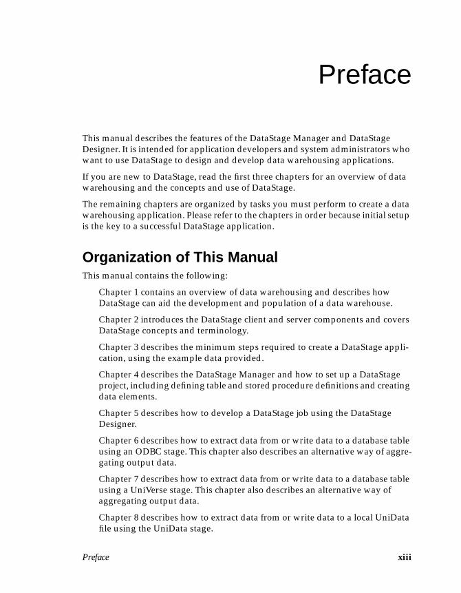
This manual describes the features of the DataStage Manager and DataStageDesigner. It is intended for application developers and system administrators whowant to use DataStage to design and develop data warehousing applications.
If you are new to DataStage, read the first three chapters for an overview of datawarehousing and the concepts and use of DataStage.
The remaining chapters are organized by tasks you must perform to create a datawarehousing application. Please refer to the chapters in order because initial setupis the key to a successful DataStage application.
Organization of This ManualThis manual contains the following:
Chapter 1 contains an overview of data warehousing and describes howDataStage can aid the development and population of a data warehouse.
Chapter 2 introduces the DataStage client and server components and coversDataStage concepts and terminology.
Chapter 3 describes the minimum steps required to create a DataStage appli-cation, using the example data provided.
Chapter 4 describes the DataStage Manager and how to set up a DataStageproject, including defining table and stored procedure definitions and creatingdata elements.
Chapter 5 describes how to develop a DataStage job using the DataStageDesigner.
Chapter 6 describes how to extract data from or write data to a database tableusing an ODBC stage. This chapter also describes an alternative way of aggre-gating output data.
Chapter 7 describes how to extract data from or write data to a database tableusing a UniVerse stage. This chapter also describes an alternative way ofaggregating output data.
Chapter 8 describes how to extract data from or write data to a local UniDatafile using the UniData stage.
xiv DataStage Developer’s Guide
Chapter 9 describes how to extract data from or write data to a local UniVersefile using the Hashed File stage.
Chapter 10 describes how to extract data from or write data to a sequential fileusing the Sequential File stage.
Chapter 11 describes how to transform (convert) data using a Transformerstage.
Chapter 12 describes how to aggregate output data using the Aggregatorstage.
Chapter 13 introduces Plug-ins and describes how to create and use them in aPlug-in stage.
Chapter 14 describes how to bulk load data into a Microsoft SQL Server orSybase database table using the BCPLoad Plug-in stage.
Chapter 15 describes how to bulk load data into an Oracle database table usingthe Orabulk Plug-in stage.
Chapter 16 describes how to write and test BASIC routines that are used asbefore-subroutines and after-subroutines or transform functions.
Chapter 17 describes how to debug, compile, and release a DataStage job.
Chapter 18 covers how to generate reports from the DataStage Manager andDesigner, and how to print from the DataStage Manager and Designer.
Chapter 19 describes how to import and export DataStage componentsbetween development environments, and how to package jobs for deploymentto other systems.
Appendix A describes the built-in transforms and routines supplied withDataStage.
Appendix B covers how to navigate and edit the grids that appear in manyDataStage dialog boxes.
Appendix C gives troubleshooting advice.
Preface xv
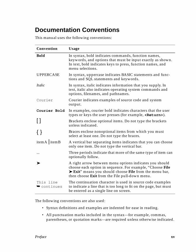
Documentation ConventionsThis manual uses the following conventions:
The following conventions are also used:
• Syntax definitions and examples are indented for ease in reading.
• All punctuation marks included in the syntax—for example, commas,parentheses, or quotation marks—are required unless otherwise indicated.
Convention Usage
Bold In syntax, bold indicates commands, function names,keywords, and options that must be input exactly as shown.In text, bold indicates keys to press, function names, andmenu selections.
UPPERCASE In syntax, uppercase indicates BASIC statements and func-tions and SQL statements and keywords.
Italic In syntax, italic indicates information that you supply. Intext, italic also indicates operating system commands andoptions, filenames, and pathnames.
Courier Courier indicates examples of source code and systemoutput.
Courier Bold In examples, courier bold indicates characters that the usertypes or keys the user presses (for example, <Return> ).
[ ] Brackets enclose optional items. Do not type the bracketsunless indicated.
{ } Braces enclose nonoptional items from which you mustselect at least one. Do not type the braces.
itemA | itemB A vertical bar separating items indicates that you can chooseonly one item. Do not type the vertical bar.
... Three periods indicate that more of the same type of item canoptionally follow.
➤ A right arrow between menu options indicates you shouldchoose each option in sequence. For example, “Choose File➤ Exit” means you should choose File from the menu bar,then choose Exit from the File pull-down menu.
This line➥ continues
The continuation character is used in source code examplesto indicate a line that is too long to fit on the page, but mustbe entered as a single line on screen.
xvi DataStage Developer’s Guide
• Syntax lines that do not fit on one line in this manual are continued onsubsequent lines. The continuation lines are indented. When enteringsyntax, type the entire syntax entry, including the continuation lines, on thesame input line.
DataStage DocumentationDataStage documentation includes the following:
DataStage Developer’s Guide: This guide describes the DataStage Managerand Designer, and how to create, design, and develop a DataStage application.
DataStage Operator’s Guide: This guide describes the DataStage Director andhow to validate, schedule, run, and monitor DataStage applications.
DataStage Administrator’s Guide: This guide describes DataStage setup,routine housekeeping, and administration.
These guides are also available online in PDF format. You can read them with theAdobe Acrobat Reader supplied with DataStage. See DataStage Installation Instruc-tions in the DataStage CD jewel case for details on installing the manuals and theAdobe Acrobat Reader.
Introduction 1-1
1Introduction
This chapter is an overview of data warehousing and DataStage.
The last few years have seen the continued growth of IT (information technology)and the requirement of organizations to make better use of the data they have attheir disposal. This involves analyzing data in active databases and comparing itwith data in archive systems.
Although offering the advantage of a competitive edge, the cost of consolidatingdata into a data mart or data warehouse was high. It also required the use of datawarehousing tools from a number of vendors and the skill to create a datawarehouse.
Developing a data warehouse or data mart involves design of the data warehouseand development of operational processes to populate and maintain it. In additionto the initial setup, you must be able to handle on-going evolution to accommodatenew data sources, processing, and goals.
DataStage from Ardent simplifies the data warehousing process. It is an integratedproduct that supports extraction of the source data, cleansing, decoding, transfor-mation, integration, aggregation, and loading of target databases.
Although primarily aimed at data warehousing environments, DataStage can alsobe used in any data handling, data migration, or data reengineering projects.
About Data WarehousingThe aim of data warehousing is to make more effective use of the data available inan organization and to aid decision-making processes.
A data warehouse is a central integrated database containing data from all theoperational sources and archive systems in an organization. It contains a copy oftransaction data specifically structured for query analysis. This database can beaccessed by all users, ensuring that each group in an organization is accessingvaluable, stable data.
1-2 DataStage Developer’s Guide
A data warehouse is a “snapshot” of the operational databases combined with datafrom archives. The data warehouse can be created or updated at any time, withminimum disruption to operational systems. Any number of analyses can beperformed on the data, which would otherwise be impractical on the operationalsources.
Operational Databases Versus Data WarehousesOperational databases are usually accessed by many concurrent users. The data inthe database changes quickly and often. It is very difficult to obtain an accuratepicture of the contents of the database at any one time.
Because operational databases are task oriented, for example, stock inventorysystems, they are likely to contain “dirty” data. The high throughput of data intooperational databases makes it difficult to trap mistakes or incomplete entries.However, you can cleanse data before loading it into a data warehouse, ensuringthat you store only “good” complete records.
Constructing the Data WarehouseA data warehouse is created by extracting data from one or more operational data-bases. The data is transformed to eliminate inconsistencies, aggregated tosummarize data, and loaded into the data warehouse. The end result is a dedicateddatabase which contains stable, nonvolatile, integrated data. This data also repre-sents a number of time variants (for example, daily, weekly, or monthly values),allowing the user to analyze trends in the data.
The data in a data warehouse is classified based on the subjects of interest to theorganization. For a bank, these subjects may be customer, account number, andtransaction details. For a retailer, these may include product, price, quantity sold,and order number.
Each data warehouse includes detailed data. However, where only a portion of thisdetailed data is required, a data mart may be more suitable. A data mart is gener-ated from the data contained in the data warehouse and contains focused data thatis frequently accessed or summarized, for example, sales or marketing data.
The person who constructs the data warehouse must know the needs of users whowill use the data warehouse or data marts. This means knowing the data containedin each operational database and how each database is related (if at all).
Introduction 1-3
Defining the Data WarehouseDefining the warehouse is one of the first steps in creating a data warehouse. Thedefinition describes the content of the data warehouse by specifying the dataelements and any transforms (conversions) required before the data is stored. Thedefinition of the data warehouse is described in terms of metadata. Metadata isdata about the data you are handling – typically a set of column definitionsdescribing the structure of the data.
Metadata can be created using the schemas or subschemas that are used to definethe operational databases. Although metadata can be difficult to define and be atime-consuming process, it holds the key to a successful data warehouse.
Data ExtractionThe data in operational or archive systems is the primary source of data for thedata warehouse. Operational databases can be indexed files, networked databases,or relational database systems. Data extraction is the process used to obtain datafrom operational sources, archives, and external data sources.
Data AggregationAn operational data source usually contains records of individual transactionssuch as product sales. If the user of a data warehouse only needs a summed total,you can reduce records to a more manageable number by aggregating the data.
The summed (aggregated) total is stored in the data warehouse. Because thenumber of records stored in the data warehouse is greatly reduced, it is easier forthe end user to browse and analyze the data.
Data TransformationBecause the data in a data warehouse comes from many sources, the data may bein different formats or be inconsistent. Transformation is the process that convertsdata to a required definition and value.
Data is transformed using routines based on a transformation rule, for example,product codes can be mapped to a common format using a transformation rulethat applies only to product codes.
After data has been transformed it can be loaded into the data warehouse in arecognized and required format.
1-4 DataStage Developer’s Guide
Advantages of Data WarehousingA data warehousing strategy provides the following advantages:
• Capitalizes on the potential value of the organization’s information
• Improves the quality and accessibility of data
• Combines valuable archive data with the latest data in operational sources
• Increases the amount of information available to users
• Reduces the requirement of users to access operational data
• Reduces the strain on IT departments, as they can produce one database toserve all user groups
• Allows new reports and studies to be introduced without disrupting opera-tional systems
• Promotes users to be self sufficient
Main Features in DataStageDataStage has the following features to aid the design and processing required tobuild a data warehouse:
• Uses graphical design tools. With simple point and click techniques youcan draw a scheme to represent your processing requirements.
• Extracts data from any number or types of database.
• Handles all the metadata definitions required to define your data ware-house. You can view and modify the table definitions at any point duringthe design of your application.
• Aggregates data. You can modify SQL SELECT statements used to extractdata.
• Transforms data. DataStage has a set of predefined transforms and func-tions you can use to convert your data. You can easily extend thefunctionality by defining your own transforms to use.
• Loads the data warehouse.
DataStage consists of a number of client and server components. For more infor-mation, see “Client Components” on page 2-1 and “Server Components” onpage 2-2.
About DataStage 2-1
2About DataStage
DataStage is a tool set for designing, developing, and running applications thatpopulate one or more tables in a data warehouse or data mart.
This chapter provides:
• A basic introduction to DataStage components and concepts• A description of the DataStage terms used throughout this manual
How DataStage Is PackagedDataStage consists of client and server components. The client and server compo-nents installed depend on the edition of DataStage you have purchased. DataStageis packaged in two ways:
• Developer’s Edition. Used by developers to design, develop, and createexecutable DataStage jobs. Contains all the client and server componentsdescribed next.
• Operator’s Edition. Used by operators to validate, schedule, run, andmonitor executable DataStage jobs. Contains the DataStage Director andServer components. The DataStage Director and the operator’s role aredescribed in DataStage Operator’s Guide.
Client ComponentsDataStage has four client components which are installed on any PC runningWindows 95 or Windows NT 4.0:
• DataStage Designer. A design interface used to create DataStage applica-tions (known as jobs). Each job specifies the data sources, the transformsrequired, and the destination of the data. Jobs are compiled to createexecutables that are scheduled by the Director and run by the Server.
2-2 DataStage Developer’s Guide
• DataStage Director. A user interface used to validate, schedule, run, andmonitor DataStage jobs.
• DataStage Manager. A user interface used to view and edit the contents ofthe Repository.
• DataStage Administrator. A user interface used to set up DataStage users,create and move projects, and set up purging criteria.
Server ComponentsThere are three server components:
• Repository. A central store that contains all the information required tobuild a data mart or data warehouse.
• DataStage Server. Runs executable jobs that extract, transform, and loaddata into a data warehouse.
• DataStage Package Installer. A user interface used to install packagedDataStage jobs and Plug-ins.
DataStage ProjectsYou always enter DataStage through a DataStage project. When you start aDataStage client you are prompted to attach to a project. Each project contains:
• DataStage jobs.
• Built-in components. These are predefined components used in a job.
• User-defined components. These are customized components createdusing the DataStage Manager. Each user-defined component performs aspecific task in a job.
A complete project may contain several jobs and user-defined components.
DataStage JobsDataStage jobs consist of individual stages. Each stage describes a particular data-base or process. For example, one stage may extract data from a data source, whileanother transforms it. Stages are added to a job and linked together using theDesigner.

About DataStage 2-3
There are two types of stage:
• Built-in stages. Supplied with DataStage and used for extracting, aggre-gating, transforming, or writing data.
• Plug-in stages. Additional stages defined in the DataStage Manager toperform tasks that the built-in stages do not support.
The following diagram represents one of the simplest jobs you could have: a datasource, a transformer (conversion) stage, and the final database. The links betweenthe stages represent the flow of data into or out of a stage.
You must specify the data you want at each stage, and how it is handled. Forexample, do you want all the columns in the source data, or only a select few?Should the data be aggregated or converted before being passed on to the nextstage?
Project-wide data properties determine the possible operations on your data.These properties are available to all the jobs in your project and consist of:
• Table definitions. These specify the data you want. Each table definitioncontains:
– Information about the table or file that holds the data records.– A description of the individual columns.
• Data elements. Each data element describes one type of data that can bestored in a column. The data element associated with a column defines theoperations that can be carried out on that column. DataStage has numerouspredefined data elements representing commonly required data types (forexample, date, time, number, string), but you can also define your ownspecial data elements.
• Transforms. These convert and cleanse your data by transforming it into aformat you want to save and use in your final warehouse.
2-4 DataStage Developer’s Guide
An executable job is created when you compile a job design. When the job is run,the processing stages described in the job design are performed using the dataproperties you defined. Executable jobs can be packaged for use on otherDataStage systems.
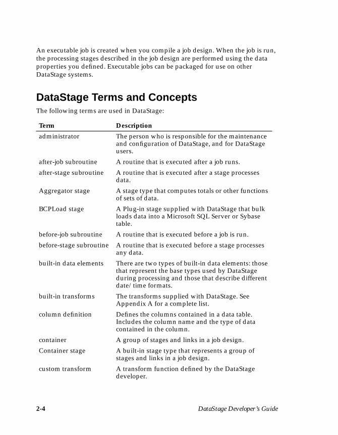
DataStage Terms and ConceptsThe following terms are used in DataStage:
Term Description
administrator The person who is responsible for the maintenanceand configuration of DataStage, and for DataStageusers.
after-job subroutine A routine that is executed after a job runs.
after-stage subroutine A routine that is executed after a stage processesdata.
Aggregator stage A stage type that computes totals or other functionsof sets of data.
BCPLoad stage A Plug-in stage supplied with DataStage that bulkloads data into a Microsoft SQL Server or Sybasetable.
before-job subroutine A routine that is executed before a job is run.
before-stage subroutine A routine that is executed before a stage processesany data.
built-in data elements There are two types of built-in data elements: thosethat represent the base types used by DataStageduring processing and those that describe differentdate/time formats.
built-in transforms The transforms supplied with DataStage. SeeAppendix A for a complete list.
column definition Defines the columns contained in a data table.Includes the column name and the type of datacontained in the column.
container A group of stages and links in a job design.
Container stage A built-in stage type that represents a group ofstages and links in a job design.
custom transform A transform function defined by the DataStagedeveloper.
About DataStage 2-5
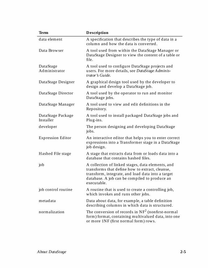
data element A specification that describes the type of data in acolumn and how the data is converted.
Data Browser A tool used from within the DataStage Manager orDataStage Designer to view the content of a table orfile.
DataStageAdministrator
A tool used to configure DataStage projects andusers. For more details, see DataStage Adminis-trator’s Guide.
DataStage Designer A graphical design tool used by the developer todesign and develop a DataStage job.
DataStage Director A tool used by the operator to run and monitorDataStage jobs.
DataStage Manager A tool used to view and edit definitions in theRepository.
DataStage PackageInstaller
A tool used to install packaged DataStage jobs andPlug-ins.
developer The person designing and developing DataStagejobs.
Expression Editor An interactive editor that helps you to enter correctexpressions into a Transformer stage in a DataStagejob design.
Hashed File stage A stage that extracts data from or loads data into adatabase that contains hashed files.
job A collection of linked stages, data elements, andtransforms that define how to extract, cleanse,transform, integrate, and load data into a targetdatabase. A job can be compiled to produce anexecutable.
job control routine A routine that is used to create a controlling job,which invokes and runs other jobs.
metadata Data about data, for example, a table definitiondescribing columns in which data is structured.
normalization The conversion of records in NF2 (nonfirst-normalform) format, containing multivalued data, into oneor more 1NF (first normal form) rows.
Term Description
2-6 DataStage Developer’s Guide
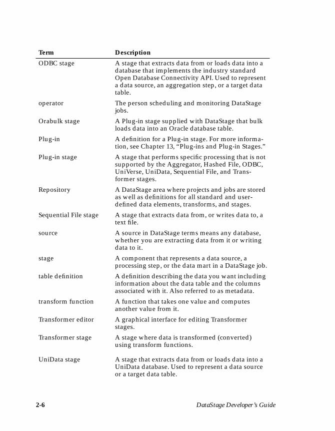
ODBC stage A stage that extracts data from or loads data into adatabase that implements the industry standardOpen Database Connectivity API. Used to representa data source, an aggregation step, or a target datatable.
operator The person scheduling and monitoring DataStagejobs.
Orabulk stage A Plug-in stage supplied with DataStage that bulkloads data into an Oracle database table.
Plug-in A definition for a Plug-in stage. For more informa-tion, see Chapter 13, “Plug-ins and Plug-in Stages.”
Plug-in stage A stage that performs specific processing that is notsupported by the Aggregator, Hashed File, ODBC,UniVerse, UniData, Sequential File, and Trans-former stages.
Repository A DataStage area where projects and jobs are storedas well as definitions for all standard and user-defined data elements, transforms, and stages.
Sequential File stage A stage that extracts data from, or writes data to, atext file.
source A source in DataStage terms means any database,whether you are extracting data from it or writingdata to it.
stage A component that represents a data source, aprocessing step, or the data mart in a DataStage job.
table definition A definition describing the data you want includinginformation about the data table and the columnsassociated with it. Also referred to as metadata.
transform function A function that takes one value and computesanother value from it.
Transformer editor A graphical interface for editing Transformerstages.
Transformer stage
UniData stage
A stage where data is transformed (converted)using transform functions.
A stage that extracts data from or loads data into aUniData database. Used to represent a data sourceor a target data table.
Term Description
About DataStage 2-7
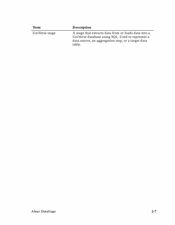
UniVerse stage A stage that extracts data from or loads data into aUniVerse database using SQL. Used to represent adata source, an aggregation step, or a target datatable.
Term Description

2-8 DataStage Developer’s Guide
Your First DataStage Project 3-1
3Your First
DataStage Project
This chapter describes the steps you need to follow to create your first data ware-house, using the sample data provided. The example uses a UniVerse table calledEXAMPLE1, which is automatically copied into your DataStage project duringserver installation.
EXAMPLE1 represents an SQL table from a wholesaler who deals in car parts. Itcontains details of the wheels they have in stock. There are approximately 255 rowsof data and four columns:
• CODE. The product code for each type of wheel.
• PRODUCT. A text description of each type of wheel.
• DATE. The date new wheels arrived in stock (given in terms of year,month, and day).
• QTY. The number of wheels in stock.
The aim of this example is to develop and run a DataStage job that:
• Extracts the data from the file.
• Converts (transforms) the data in the DATE column from a complete date(YYYY-MM-DD) stored in internal data format, to a year and month(YYYY-MM) stored as a string.
• Loads data from the DATE, CODE, and QTY columns into a data ware-house. The data warehouse is a sequential file that is created when you runthe job.
To load a data mart or data warehouse, you must do the following:
• Set up your project• Create a job
3-2 DataStage Developer’s Guide
• Develop the job• Edit the stages in the job• Compile the job• Run the job
This chapter describes the minimum tasks required to create a DataStage job. In theexample, you will use the built-in settings and options supplied with DataStage.However, because DataStage allows you to customize and extend the built-in func-tionality provided, it is possible to perform additional processing at each step.Where this is possible, additional procedures are listed under a section calledAdvanced Procedures. These advanced procedures are discussed in detail in subse-quent chapters.
Setting Up Your ProjectBefore you create any DataStage jobs, you must set up your project by enteringinformation about your data. This includes the name and location of the tables orfiles holding your data and a definition of the columns they contain.
Information is stored in table definitions in the Repository and is entered using theDataStage Manager. The easiest way to enter a table definition is to import directlyfrom the source data.
In this example, you need a table definition for EXAMPLE1.
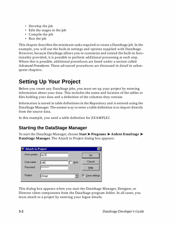
Starting the DataStage ManagerTo start the DataStage Manager, choose Start ➤ Programs ➤ Ardent DataStage ➤DataStage Manager. The Attach to Project dialog box appears:
This dialog box appears when you start the DataStage Manager, Designer, orDirector client components from the DataStage program folder. In all cases, youmust attach to a project by entering your logon details.
Your First DataStage Project 3-3
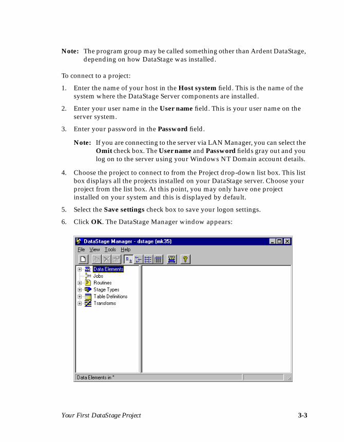
Note: The program group may be called something other than Ardent DataStage,depending on how DataStage was installed.
To connect to a project:
1. Enter the name of your host in the Host system field. This is the name of thesystem where the DataStage Server components are installed.
2. Enter your user name in the User name field. This is your user name on theserver system.
3. Enter your password in the Password field.
Note: If you are connecting to the server via LAN Manager, you can select theOmit check box. The User name and Password fields gray out and youlog on to the server using your Windows NT Domain account details.
4. Choose the project to connect to from the Project drop-down list box. This listbox displays all the projects installed on your DataStage server. Choose yourproject from the list box. At this point, you may only have one projectinstalled on your system and this is displayed by default.
5. Select the Save settings check box to save your logon settings.
6. Click OK. The DataStage Manager window appears:
3-4 DataStage Developer’s Guide
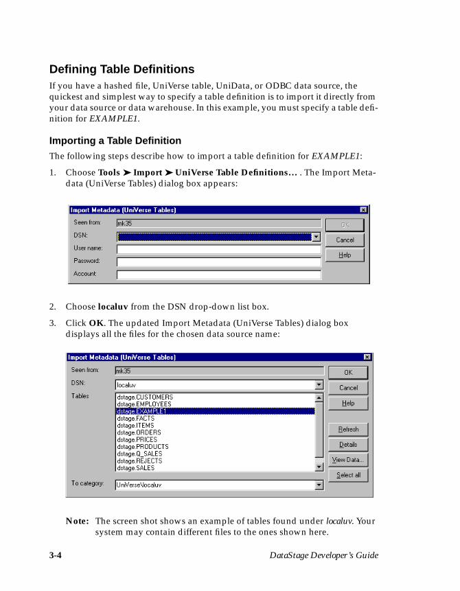
Defining Table DefinitionsIf you have a hashed file, UniVerse table, UniData, or ODBC data source, thequickest and simplest way to specify a table definition is to import it directly fromyour data source or data warehouse. In this example, you must specify a table defi-nition for EXAMPLE1.
Importing a Table DefinitionThe following steps describe how to import a table definition for EXAMPLE1:
1. Choose Tools ➤ Import ➤ UniVerse Table Definitions… . The Import Meta-data (UniVerse Tables) dialog box appears:
2. Choose localuv from the DSN drop-down list box.
3. Click OK. The updated Import Metadata (UniVerse Tables) dialog boxdisplays all the files for the chosen data source name:
Note: The screen shot shows an example of tables found under localuv. Yoursystem may contain different files to the ones shown here.
Your First DataStage Project 3-5
4. Select project.EXAMPLE1 from the Tables list box, where project is the nameof your DataStage project.
5. Click OK. The column information from EXAMPLE1 is imported intoDataStage. A table definition is created and is stored under the Table Defini-tions ➤ UniVerse ➤ localuv branch in the Repository. The DataStageManager window updates to display the new table definition entry in thedisplay area.
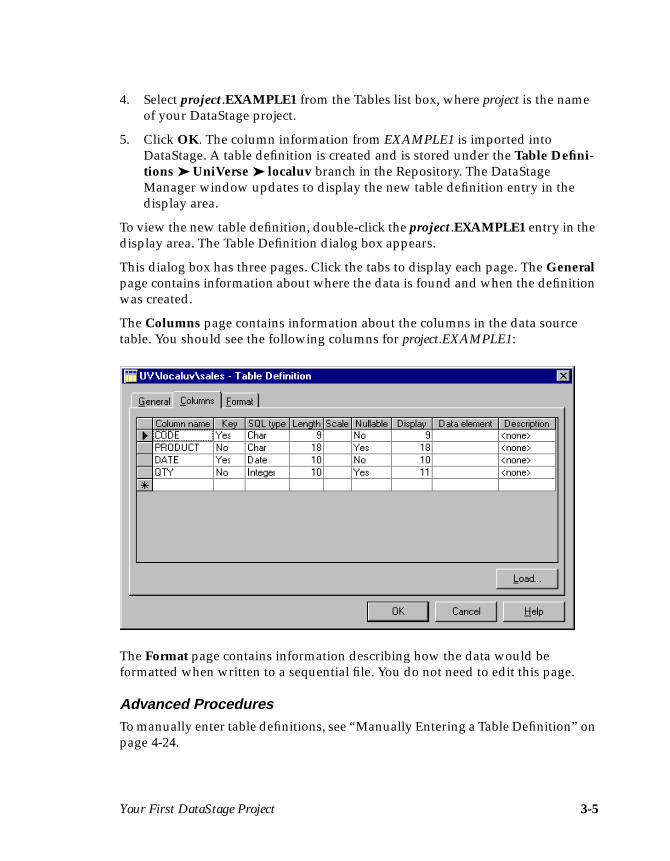
To view the new table definition, double-click the project.EXAMPLE1 entry in thedisplay area. The Table Definition dialog box appears.
This dialog box has three pages. Click the tabs to display each page. The Generalpage contains information about where the data is found and when the definitionwas created.
The Columns page contains information about the columns in the data sourcetable. You should see the following columns for project.EXAMPLE1:
The Format page contains information describing how the data would beformatted when written to a sequential file. You do not need to edit this page.
Advanced ProceduresTo manually enter table definitions, see “Manually Entering a Table Definition” onpage 4-24.
3-6 DataStage Developer’s Guide
Assigning Data ElementsA DataStage data element describes more precisely the kind of data that canappear in a given column. When you import a table definition, no DataStage dataelements are set. You can apply a DataStage data element to give more meaning toa particular column and to specify a transform to use. Transforms are defined suchthat they convert one data element to another.
In this example, to transform the data in the DATE column, you assign a DataStagedata element. Initially you assign the Date type. (Later, in the Transformer stage,you will assign a MONTH.TAG data element to the output column to specify thatthe transform produces a string of the format YYYY-MM.)
Note: If the data in the other columns required transforming, you could assignDataStage data elements to these columns too.
To assign a data element:
1. Click the Data element cell for the DATE row in the Columns grid.
2. Choose Date from the Data element drop-down list box.
3. Click OK to save the table definition and to close the Table Definition dialogbox.
Advanced ProceduresFor more advanced procedures, see the following topics in Chapter 4:
• “Creating Data Elements” on page 4-38• “Assigning Data Elements” on page 4-40
Creating a JobWhen a DataStage project is installed, it is empty and you must create the jobs youneed. Each DataStage job can load one or more data tables in the final data ware-house. The number of jobs you have in a project depends on your data sources andhow often you want to extract data or load the data warehouse.
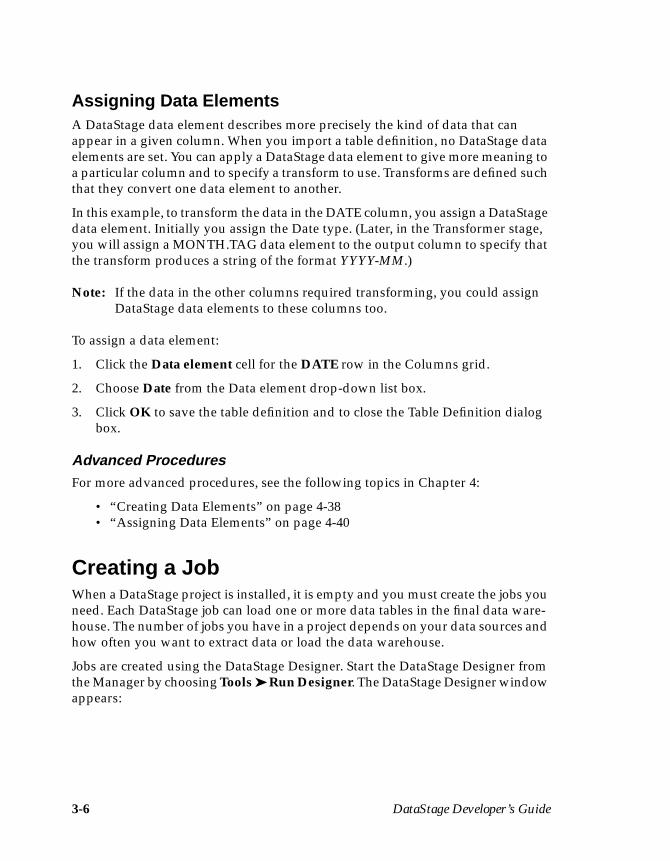
Jobs are created using the DataStage Designer. Start the DataStage Designer fromthe Manager by choosing Tools ➤ Run Designer. The DataStage Designer windowappears:
Your First DataStage Project 3-7
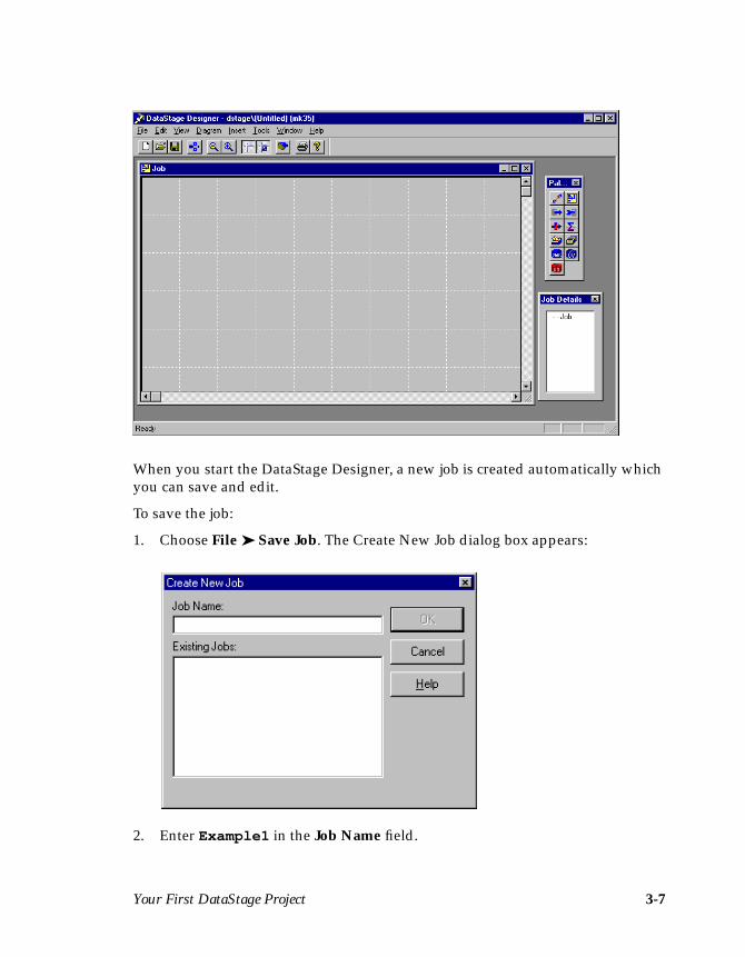
When you start the DataStage Designer, a new job is created automatically whichyou can save and edit.
To save the job:
1. Choose File ➤ Save Job. The Create New Job dialog box appears:
2. Enter Example1 in the Job Name field.
3-8 DataStage Developer’s Guide
3. Click OK to save the job. The DataStage Designer window is updated todisplay the name of the saved job.
Developing a JobJobs are designed and developed using the Designer. The job design is developedin the Diagram window (the one with grid lines). Each data source, the data ware-house, and each processing step is represented by a stage in the job design. Thestages are linked together to show the flow of data.
This example requires three stages:
• A UniVerse stage to represent EXAMPLE1 (the data source)
• A Transformer stage to convert the data in the DATE column from a YYYY-MM-DD date in internal date format to a string giving just year and month(YYYY-MM)
• A Sequential File stage to represent the file created at run time (the datawarehouse in this example)
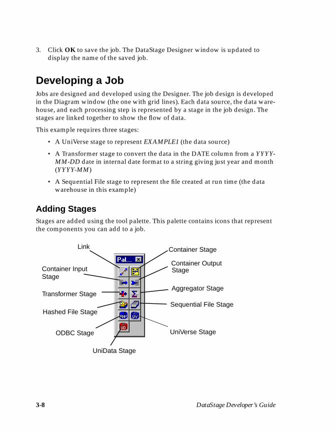
Adding StagesStages are added using the tool palette. This palette contains icons that representthe components you can add to a job.
Container Output
Aggregator Stage
Sequential File Stage
Stage
Link
Container InputStage
Hashed File Stage
Transformer Stage
Container Stage
ODBC Stage UniVerse Stage
UniData Stage
Your First DataStage Project 3-9
To add a stage:
1. Click the stage icon on the tool palette that represents the stage type you wantto add.
2. Click in the Diagram window where you want the stage to be positioned. Thestage appears in the Diagram window as a square.
We recommend that you position your stages as follows:
• Data sources on the left• Data warehouse on the right• Transformer stage in the center
When you add stages, they are automatically assigned default names. Thesenames are based on the type of stage and the number of the item in the Diagramwindow. You can use the default names in the example.
Once all the stages are in place, you can link them together to show the flow ofdata.
Linking StagesYou need to add two links:
• One between the UniVerse and Transformer stages• One between the Transformer and Sequential File stages
Links are always made in the direction the data will flow, that is, usually left toright. When you add links, they are assigned default names. You can use thedefault names in the example.
To add a link:
1. Click the Link icon on the tool palette.
2. Click the first stage and drag the link to the Transformer stage. The linkappears as soon as you release the mouse button.
3. Click the Link icon on the tool palette again.
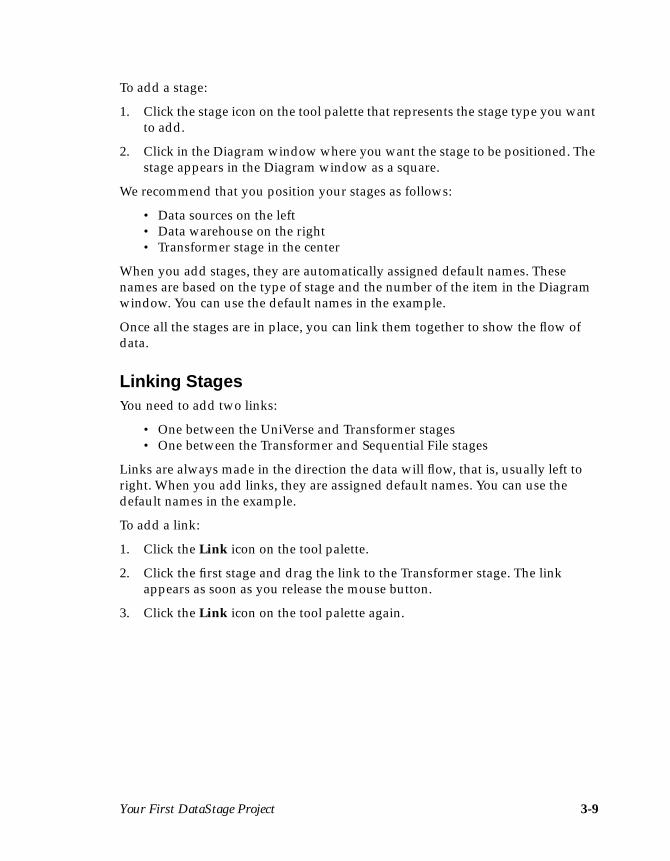
3-10 DataStage Developer’s Guide
4. Click the Transformer stage and drag the link to the Sequential File stage. Thefollowing screen shows how the Diagram window looks when you haveadded the stages and links:
5. Save the job design by choosing File ➤ Save Job.
Keep the Designer open as you will need it for the next step.
Advanced ProceduresFor more advanced procedures, see the following topics in Chapter 5:
• “Plug-in Stages” on page 5-12• “Moving Stages” on page 5-14• “Renaming Stages” on page 5-14• “Deleting Stages” on page 5-14• “Containers” on page 5-27• “Specifying Job Parameters” on page 5-32
Editing the StagesYour job design currently displays the stages and the links between them. Youmust edit each stage in the job to specify the data to use and what to do with it.Stages are edited in the job design by double-clicking each stage in turn. Each stagetype has its own editor.
Your First DataStage Project 3-11
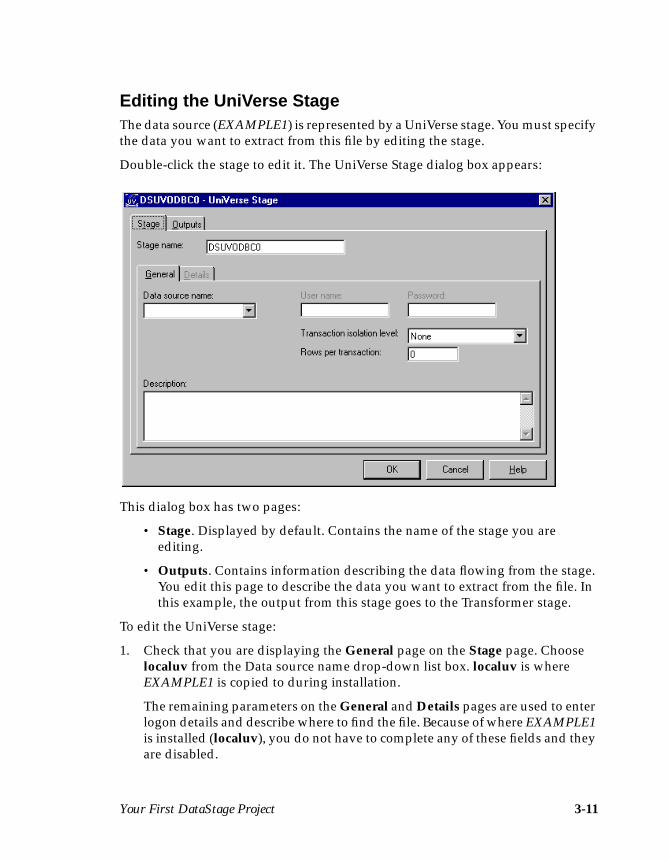
Editing the UniVerse StageThe data source (EXAMPLE1) is represented by a UniVerse stage. You must specifythe data you want to extract from this file by editing the stage.
Double-click the stage to edit it. The UniVerse Stage dialog box appears:
This dialog box has two pages:
• Stage. Displayed by default. Contains the name of the stage you areediting.
• Outputs. Contains information describing the data flowing from the stage.You edit this page to describe the data you want to extract from the file. Inthis example, the output from this stage goes to the Transformer stage.
To edit the UniVerse stage:
1. Check that you are displaying the General page on the Stage page. Chooselocaluv from the Data source name drop-down list box. localuv is whereEXAMPLE1 is copied to during installation.
The remaining parameters on the General and Details pages are used to enterlogon details and describe where to find the file. Because of where EXAMPLE1is installed (localuv), you do not have to complete any of these fields and theyare disabled.
3-12 DataStage Developer’s Guide
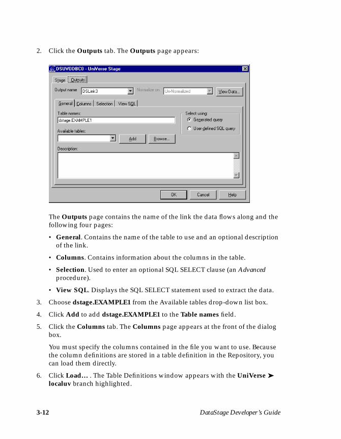
2. Click the Outputs tab. The Outputs page appears:
The Outputs page contains the name of the link the data flows along and thefollowing four pages:
• General. Contains the name of the table to use and an optional descriptionof the link.
• Columns. Contains information about the columns in the table.
• Selection. Used to enter an optional SQL SELECT clause (an Advancedprocedure).
• View SQL. Displays the SQL SELECT statement used to extract the data.
3. Choose dstage.EXAMPLE1 from the Available tables drop-down list box.
4. Click Add to add dstage.EXAMPLE1 to the Table names field.
5. Click the Columns tab. The Columns page appears at the front of the dialogbox.
You must specify the columns contained in the file you want to use. Becausethe column definitions are stored in a table definition in the Repository, youcan load them directly.
6. Click Load… . The Table Definitions window appears with the UniVerse ➤localuv branch highlighted.
Your First DataStage Project 3-13
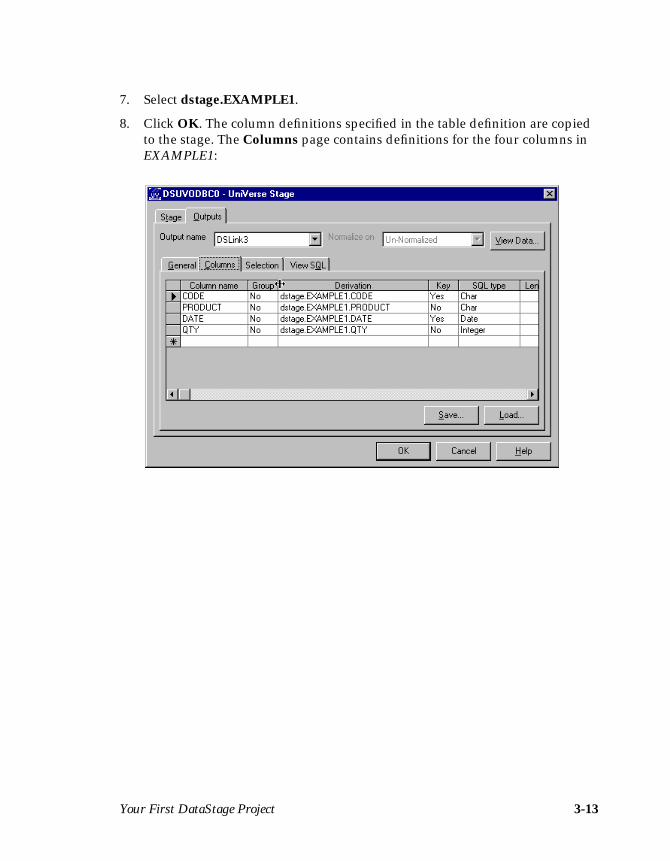
7. Select dstage.EXAMPLE1.
8. Click OK. The column definitions specified in the table definition are copiedto the stage. The Columns page contains definitions for the four columns inEXAMPLE1:
3-14 DataStage Developer’s Guide
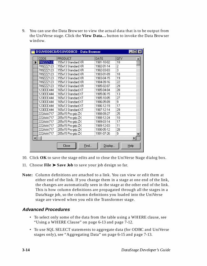
9. You can use the Data Browser to view the actual data that is to be output fromthe UniVerse stage. Click the View Data… button to invoke the Data Browserwindow.
10. Click OK to save the stage edits and to close the UniVerse Stage dialog box.
11. Choose File ➤ Save Job to save your job design so far.
Note: Column definitions are attached to a link. You can view or edit them ateither end of the link. If you change them in a stage at one end of the link,the changes are automatically seen in the stage at the other end of the link.This is how column definitions are propagated through all the stages in aDataStage job, so the column definitions you loaded into the UniVersestage are viewed when you edit the Transformer stage.
Advanced Procedures
• To select only some of the data from the table using a WHERE clause, see“Using a WHERE Clause” on page 6-13 and page 7-12.
• To use SQL SELECT statements to aggregate data (for ODBC and UniVersestages only), see “Aggregating Data” on page 6-15 and page 7-13.

Your First DataStage Project 3-15
Editing the Transformer StageThe Transformer stage performs any data conversion required before the data isoutput to another stage in the job design. In this example, the Transformer stage isused to convert the data in the DATE column from a YYYY-MM-DD date ininternal date format to a string giving just the year and month (YYYY-MM).
There are two links in this stage:
• The input from the data source (EXAMPLE1)• The output to the Sequential File stage
Double-click the stage to edit it. The Transformer Editor appears:
Input columns are shown on the left, output columns on the right. The upper panesshow the columns together with derivation details, the lower panes show thecolumn metadata. In this case, input columns have already been defined for inputlink DSLink3. No output columns have been defined for output link DSLink4, sothe right panes are blank.
The next steps are to define the columns that will be output by the Transformerstage, and to specify the transform that will enable the stage to convert the typeand format of dates before they are output.
1. Working in the upper-left pane of the Transformer Editor, select the inputcolumns that you want to derive output columns from. Point and click on theCODE, DATE, and QTY columns while holding down the Ctrl key.
3-16 DataStage Developer’s Guide
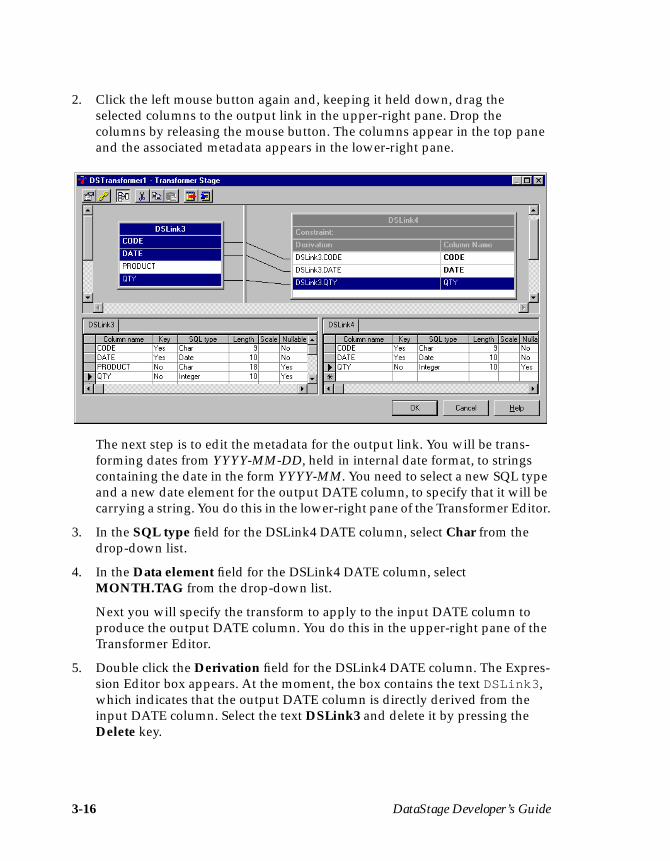
2. Click the left mouse button again and, keeping it held down, drag theselected columns to the output link in the upper-right pane. Drop thecolumns by releasing the mouse button. The columns appear in the top paneand the associated metadata appears in the lower-right pane.
The next step is to edit the metadata for the output link. You will be trans-forming dates from YYYY-MM-DD, held in internal date format, to stringscontaining the date in the form YYYY-MM. You need to select a new SQL typeand a new date element for the output DATE column, to specify that it will becarrying a string. You do this in the lower-right pane of the Transformer Editor.
3. In the SQL type field for the DSLink4 DATE column, select Char from thedrop-down list.
4. In the Data element field for the DSLink4 DATE column, selectMONTH.TAG from the drop-down list.
Next you will specify the transform to apply to the input DATE column toproduce the output DATE column. You do this in the upper-right pane of theTransformer Editor.
5. Double click the Derivation field for the DSLink4 DATE column. The Expres-sion Editor box appears. At the moment, the box contains the text DSLink3 ,which indicates that the output DATE column is directly derived from theinput DATE column. Select the text DSLink3 and delete it by pressing theDelete key.

Your First DataStage Project 3-17
6. Right-click in the Expression Editor box to invoke the Suggest Operandmenu.
7. Select DS Transform… from the menu. The Expression Editor then displaysthe transforms that are applicable to the MONTH.TAG data element:

3-18 DataStage Developer’s Guide
8. Select the MONTH.TAG transform. It appears in the Expression Editor boxwith the argument field [%Arg1%] highlighted.
9. Right-click to invoke the Suggest Operand menu again. This time, selectInput Column. A list of available input columns appears.
10. Select DSLink3.DATE. This then becomes the argument for the transform.
11. Click OK to save the changes and exit the Transformer Editor.
Advanced ProceduresTo create and use custom transforms, see “Transforms” on page 11-14.
Your First DataStage Project 3-19
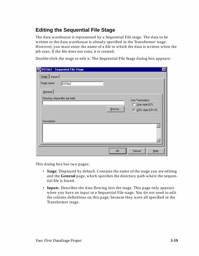
Editing the Sequential File StageThe data warehouse is represented by a Sequential File stage. The data to bewritten to the data warehouse is already specified in the Transformer stage.However, you must enter the name of a file to which the data is written when thejob runs. If the file does not exist, it is created.
Double-click the stage to edit it. The Sequential File Stage dialog box appears:
This dialog box has two pages:
• Stage. Displayed by default. Contains the name of the stage you are editingand the General page, which specifies the directory path where the sequen-tial file is found.
• Inputs. Describes the data flowing into the stage. This page only appearswhen you have an input to a Sequential File stage. You do not need to editthe column definitions on this page, because they were all specified in theTransformer stage.
3-20 DataStage Developer’s Guide
To edit the Sequential File stage:
1. Enter the directory path where the new file will be created in the Directorywhere files are held field. By default, this field is empty. If you leave it empty,the default installation directory is used. If you want to choose an alternativedirectory, click Browse… to search the DataStage server for a suitable direc-tory path.
2. Click the Inputs tab. The Inputs page appears. This page contains:
• The name of the link. This is automatically set to the link name used in thejob design.
• General page. Contains the name of the file, an optional description of thelink, and update action choices. You can use the default settings for thisexample, but you must enter a file name.
• Format page. Determines how the data is written to the file. In thisexample, the data is written using the default settings, that is, as a comma-delimited file.
• Columns page. Contains the column definitions for the data you want toextract. This page contains the column definitions specified in the Trans-former stage’s output link.
3. Enter the name of the text file you want to create in the File name field, forexample, MyFile.txt .
4. Click OK to close the Sequential File Stage dialog box.
5. Choose File ➤ Save Job to save the job design.
The job design is now complete and ready to be compiled.
Compiling a JobWhen you finish your design you must compile it to create an executable job. Jobsare compiled using the Designer. To compile the job, do one of the following:
• Choose File ➤ Compile.• Click the Compile icon on the toolbar.
Your First DataStage Project 3-21
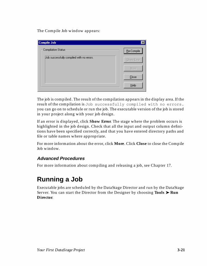
The Compile Job window appears:
The job is compiled. The result of the compilation appears in the display area. If theresult of the compilation is Job successfully compiled with no errors.you can go on to schedule or run the job. The executable version of the job is storedin your project along with your job design.
If an error is displayed, click Show Error. The stage where the problem occurs ishighlighted in the job design. Check that all the input and output column defini-tions have been specified correctly, and that you have entered directory paths andfile or table names where appropriate.
For more information about the error, click More. Click Close to close the CompileJob window.
Advanced ProceduresFor more information about compiling and releasing a job, see Chapter 17.
Running a JobExecutable jobs are scheduled by the DataStage Director and run by the DataStageServer. You can start the Director from the Designer by choosing Tools ➤ RunDirector.

3-22 DataStage Developer’s Guide
When the Director is started, the DataStage Director window appears with thestatus of all the jobs in your project:
Highlight your job in the Job name column. To run the job, choose Job ➤ Run Nowor click the Run icon on the toolbar. The Job Run Options dialog box appears andallows you to specify any parameter values and to specify any job run limits.Supply the required information, then click Run. The status changes to Running.When the job is complete, the status changes to Finished.
Choose File ➤ Exit to close the DataStage Director window.
Refer to DataStage Operator’s Guide for more information about scheduling andrunning jobs.
Advanced ProceduresIt is possible to run a job from within another job. For more information, see “JobControl Routines” on page 5-37.
Analyzing Your Data WarehouseWhen you have data in your data mart or data warehouse, you can use any BI(business intelligence) tool (for example, Cognos Impromptu or PowerPlay) toanalyze and report on the data.
In the example, you can confirm that the data was converted and loaded correctlyby viewing your text file using the Windows WordPad. (Alternatively, you coulduse the built-in Data Browser to view the data from the Outputs page of the
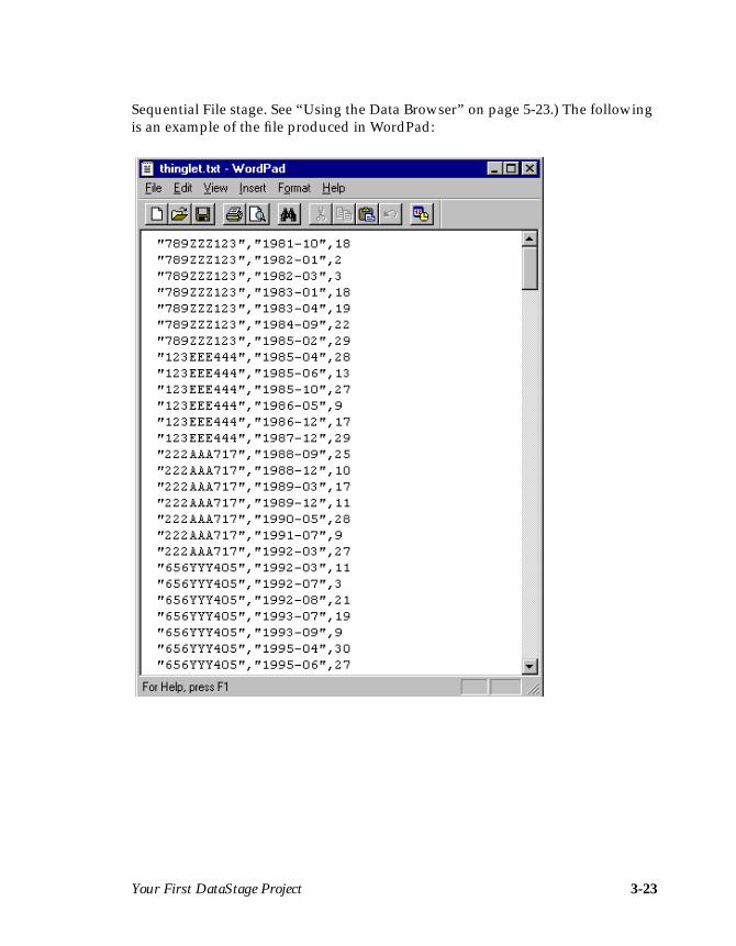
Your First DataStage Project 3-23
Sequential File stage. See “Using the Data Browser” on page 5-23.) The followingis an example of the file produced in WordPad:

3-24 DataStage Developer’s Guide

Setting Up a Project 4-1
4Setting Up a Project
This chapter describes how to set up your project using the DataStage Managerbefore you start to develop DataStage jobs.
Note: Before users can develop or run DataStage applications, you must definewho has access to the DataStage projects. This configuration is done usingthe DataStage Administrator. For more information, see DataStage Admin-istrator’s Guide.
Before you develop any DataStage job, you must plan and set up your project. Thisincludes:
• Assessing your data• Creating the data warehouse
You can then use the DataStage Manager to:
• Import, create, and edit table definitions• Import, create, and edit stored procedure definitions• Create, edit, and assign data elements
Assessing Your DataBefore you design your application you must assess your data. DataStage jobs canbe complex and so it is advisable to consider the following before starting a job:
• The number and type of data sources. You need a stage for each data sourceyou want to access. For each different type of data source you need adifferent type of stage.
• The location of the data. Is your data on a networked disk or a tape? Youmay find that if your data is on a tape, you need to arrange for a Plug-instage to extract the data.
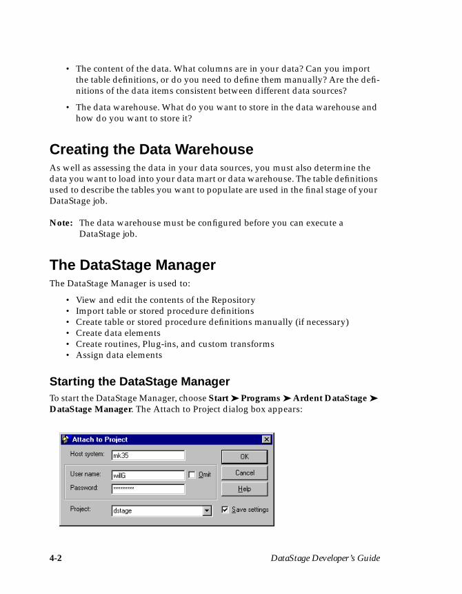
4-2 DataStage Developer’s Guide
• The content of the data. What columns are in your data? Can you importthe table definitions, or do you need to define them manually? Are the defi-nitions of the data items consistent between different data sources?
• The data warehouse. What do you want to store in the data warehouse andhow do you want to store it?
Creating the Data WarehouseAs well as assessing the data in your data sources, you must also determine thedata you want to load into your data mart or data warehouse. The table definitionsused to describe the tables you want to populate are used in the final stage of yourDataStage job.
Note: The data warehouse must be configured before you can execute aDataStage job.
The DataStage ManagerThe DataStage Manager is used to:
• View and edit the contents of the Repository• Import table or stored procedure definitions• Create table or stored procedure definitions manually (if necessary)• Create data elements• Create routines, Plug-ins, and custom transforms• Assign data elements
Starting the DataStage ManagerTo start the DataStage Manager, choose Start ➤ Programs ➤ Ardent DataStage ➤DataStage Manager. The Attach to Project dialog box appears:
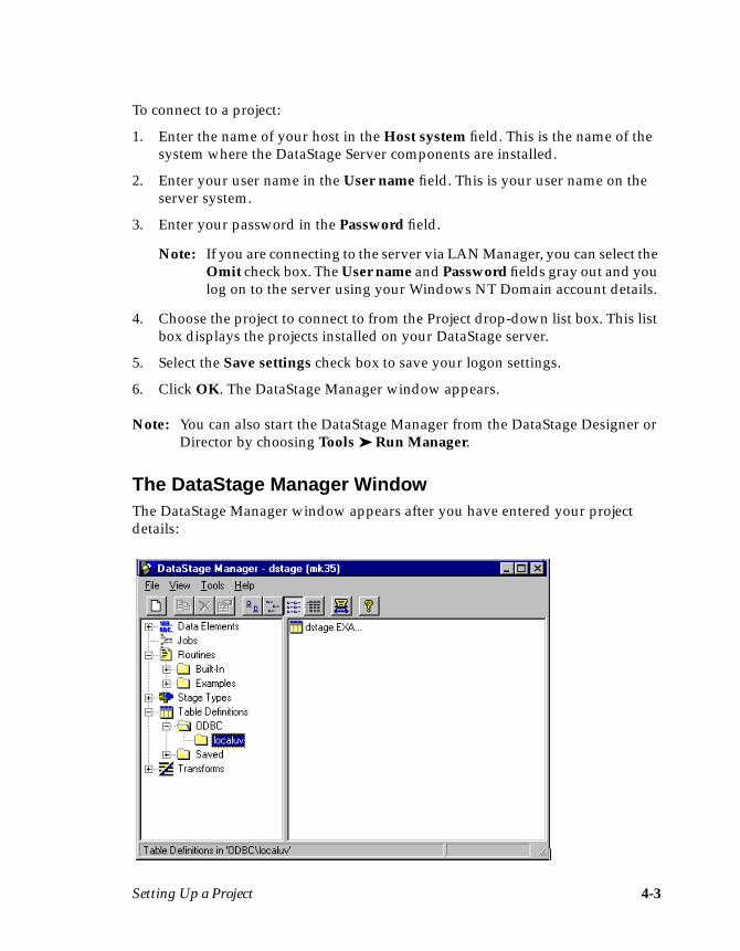
Setting Up a Project 4-3
To connect to a project:
1. Enter the name of your host in the Host system field. This is the name of thesystem where the DataStage Server components are installed.
2. Enter your user name in the User name field. This is your user name on theserver system.
3. Enter your password in the Password field.
Note: If you are connecting to the server via LAN Manager, you can select theOmit check box. The User name and Password fields gray out and youlog on to the server using your Windows NT Domain account details.
4. Choose the project to connect to from the Project drop-down list box. This listbox displays the projects installed on your DataStage server.
5. Select the Save settings check box to save your logon settings.
6. Click OK. The DataStage Manager window appears.
Note: You can also start the DataStage Manager from the DataStage Designer orDirector by choosing Tools ➤ Run Manager.
The DataStage Manager WindowThe DataStage Manager window appears after you have entered your projectdetails:
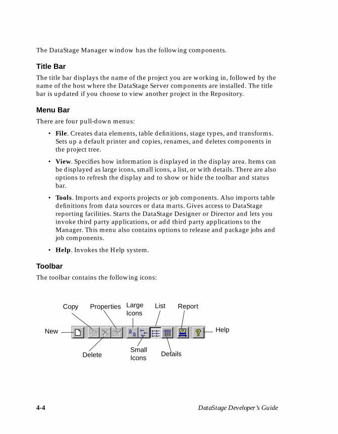
4-4 DataStage Developer’s Guide
The DataStage Manager window has the following components.
Title BarThe title bar displays the name of the project you are working in, followed by thename of the host where the DataStage Server components are installed. The titlebar is updated if you choose to view another project in the Repository.
Menu BarThere are four pull-down menus:
• File. Creates data elements, table definitions, stage types, and transforms.Sets up a default printer and copies, renames, and deletes components inthe project tree.
• View. Specifies how information is displayed in the display area. Items canbe displayed as large icons, small icons, a list, or with details. There are alsooptions to refresh the display and to show or hide the toolbar and statusbar.
• Tools. Imports and exports projects or job components. Also imports tabledefinitions from data sources or data marts. Gives access to DataStagereporting facilities. Starts the DataStage Designer or Director and lets youinvoke third party applications, or add third party applications to theManager. This menu also contains options to release and package jobs andjob components.
• Help. Invokes the Help system.
ToolbarThe toolbar contains the following icons:
New
Copy
Delete
Properties LargeIcons
SmallIcons
List
Details
Report
Help
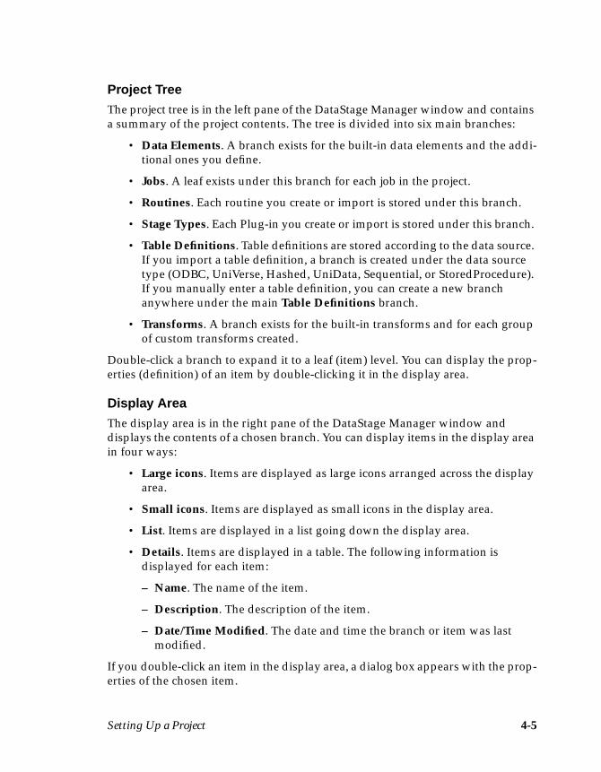
Setting Up a Project 4-5
Project TreeThe project tree is in the left pane of the DataStage Manager window and containsa summary of the project contents. The tree is divided into six main branches:
• Data Elements. A branch exists for the built-in data elements and the addi-tional ones you define.
• Jobs. A leaf exists under this branch for each job in the project.
• Routines. Each routine you create or import is stored under this branch.
• Stage Types. Each Plug-in you create or import is stored under this branch.
• Table Definitions. Table definitions are stored according to the data source.If you import a table definition, a branch is created under the data sourcetype (ODBC, UniVerse, Hashed, UniData, Sequential, or StoredProcedure).If you manually enter a table definition, you can create a new branchanywhere under the main Table Definitions branch.
• Transforms. A branch exists for the built-in transforms and for each groupof custom transforms created.
Double-click a branch to expand it to a leaf (item) level. You can display the prop-erties (definition) of an item by double-clicking it in the display area.
Display AreaThe display area is in the right pane of the DataStage Manager window anddisplays the contents of a chosen branch. You can display items in the display areain four ways:
• Large icons. Items are displayed as large icons arranged across the displayarea.
• Small icons. Items are displayed as small icons in the display area.
• List. Items are displayed in a list going down the display area.
• Details. Items are displayed in a table. The following information isdisplayed for each item:
– Name. The name of the item.
– Description. The description of the item.
– Date/Time Modified. The date and time the branch or item was lastmodified.
If you double-click an item in the display area, a dialog box appears with the prop-erties of the chosen item.
4-6 DataStage Developer’s Guide
Shortcut MenusThere are a number of shortcut menus available which you display by clicking theright mouse button. There are three types of menu:
• Branch level. Appears when you click the display area (not an item) or theproject tree. Use this menu to refresh the display or to create a new itemunder the chosen branch.
• Item level. Appears when you click a highlighted item in the display area.Use this menu to copy, rename, delete, or display the properties of thechosen item.
• Grid level. Appears when you are editing a grid. Use this menu to edit,insert, or delete a row.
Using the DataStage ManagerThe DataStage Manager provides a means of viewing and managing the contentsof the Repository. You can use the DataStage Manager to:
• Create items• Rename items• View and edit item properties• Delete items• Copy items
Creating Items in the RepositoryYou can create new data elements, table definitions, transforms, or Plug-ins. Tocreate a new item, select the top-level branch in the project tree and do one of thefollowing:
• Choose File ➤ New. The New option describes the selected item, forexample, File ➤ New Transform… .
• Choose New… from the shortcut menu.
• Click the New icon on the toolbar.
A dialog box appears for you to enter the properties of the new item. Click OK tosave the new item. A leaf is created for the item in the project tree.
Renaming Items in the RepositoryYou can rename any of the items in the project tree, except for the top-levelbranches, jobs, and built-in items.
Setting Up a Project 4-7
To rename an item, select it in the display area and do one of the following:
• Click the item again. An edit box appears and you can enter a differentname or edit the existing one. Save the new name by pressing Enter or byclicking outside the edit box.
• Double-click the item. A properties dialog box appears and you can editthe field containing the item’s name. Click OK to save the new name.
• Choose Rename from the shortcut menu. An edit box appears and you canenter a different name or edit the existing one. Save the new name bypressing Enter or by clicking outside the edit box.
Viewing or Editing Items in the RepositoryYou can view or edit the properties of any item in the project tree.
Note: You cannot edit the properties of built-in items.
To view or edit the properties of an item, select the item in the display area and doone of the following:
• Choose File ➤ Properties…• Choose Properties… from the shortcut menu• Double-click the item in the display area• Click the Properties icon on the toolbar
A dialog box appears with the item’s properties. The content of the dialog boxdepends on the type of item you are viewing or editing. Click OK to save anychanges and to close the dialog box.
Deleting Items in the RepositoryYou can delete any item in the project tree, except the built-in items.
CAUTION: You must be absolutely certain you want to remove an item in theRepository before you delete it. If it is used by another item in theproject, your jobs will fail to compile.
To delete an item, select it in the display area and do one of the following:
• Choose File ➤ Delete.• Click the Delete icon on the toolbar.
A message box appears. Click Yes to delete the item.
4-8 DataStage Developer’s Guide
Copying Items in the RepositoryYou can copy items in the same branch in the project tree. To copy an item, selectthe item in the display area and do one of the following:
• Choose File ➤ Copy.• Choose Copy from the shortcut menu.• Click the Copy icon on the toolbar.
The item is copied and a new item is created under the same branch in the projecttree. By default, the name of the copy is called CopyOfXXX, where XXX is thename of the chosen item. An edit box appears allowing you to rename the copyimmediately.
Choosing an Alternative ProjectWhen you start the DataStage Manager, the project specified in the Attach toProject dialog box is opened. You can choose to view any DataStage project in theDataStage Manager.
To choose an alternative project:
1. Choose File ➤ Open Project… . The Open Project dialog box appears.
2. Choose the project you want to open from the Projects list box. This list boxcontains all the DataStage projects on the DataStage server (specified in theHost system field).
3. Click OK to open the chosen project. The DataStage Manager window isupdated and displays the contents of the new project.
To open a project on a different DataStage server, click New host… . The Attach toProject dialog box appears. You must enter the name of the DataStage server andyour logon details before choosing the project from the Project drop-down list box.Click OK to open the chosen project. The DataStage Manager window is updatedand displays the contents of the new project.
Customizing the Tools MenuYou can configure the DataStage Manager so that you can invoke third party appli-cations from the Tools menu. To configure the menu:
1. Choose Tools ➤ Custom ➤ Customize… . The Customize dialog boxappears.
2. Click the Add… button to display the Add Tool dialog box.
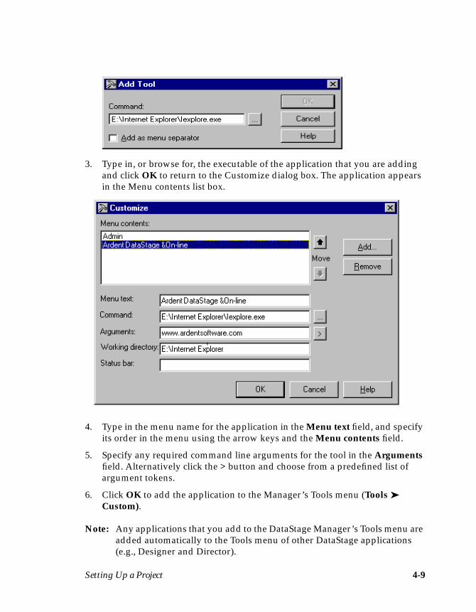
Setting Up a Project 4-9
3. Type in, or browse for, the executable of the application that you are addingand click OK to return to the Customize dialog box. The application appearsin the Menu contents list box.
4. Type in the menu name for the application in the Menu text field, and specifyits order in the menu using the arrow keys and the Menu contents field.
5. Specify any required command line arguments for the tool in the Argumentsfield. Alternatively click the > button and choose from a predefined list ofargument tokens.
6. Click OK to add the application to the Manager’s Tools menu (Tools ➤Custom).
Note: Any applications that you add to the DataStage Manager’s Tools menu areadded automatically to the Tools menu of other DataStage applications(e.g., Designer and Director).

4-10 DataStage Developer’s Guide
Exiting the DataStage ManagerTo exit the DataStage Manager, choose File ➤ Exit from the DataStage Managerwindow.
Table DefinitionsTable definitions are the key to your DataStage project and specify the data to beused at each stage of a DataStage job. Table definitions are stored in the Repositoryand are shared by all the jobs in a project. You need, as a minimum, table defini-tions for each data source and one for each data target in the data mart.
You can import, create, or edit a table definition using the DataStage Manager.
You can use the Data Browser to view the actual data in data sources from whichyou are importing table definitions.
Importing a Table DefinitionThe easiest way to specify a table definition is to import it directly from the sourceor target database. A new table definition is created and the properties are auto-matically filled in with the details of your data source or data mart.
You can import table definitions from an ODBC data source, a UniVerse table, ahashed (UniVerse) file, a UniData file, a sequential file, or some types of Plug-in.
Importing from an ODBC Data SourceTo import a table definition from a database via an ODBC connection:
1. Start the DataStage Manager and enter your logon details in the Attach toProject dialog box. The DataStage Manager window appears.
2. Choose Tools ➤ Import… ➤ ODBC Table Definitions… . The Import Meta-data (ODBC) dialog box appears:
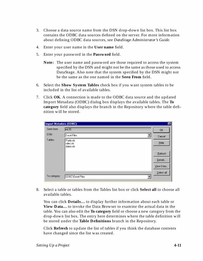
Setting Up a Project 4-11
3. Choose a data source name from the DSN drop-down list box. This list boxcontains the ODBC data sources defined on the server. For more informationabout defining ODBC data sources, see DataStage Administrator’s Guide.
4. Enter your user name in the User name field.
5. Enter your password in the Password field.
Note: The user name and password are those required to access the systemspecified by the DSN and might not be the same as those used to accessDataStage. Also note that the system specified by the DSN might notbe the same as the one named in the Seen From field.
6. Select the Show System Tables check box if you want system tables to beincluded in the list of available tables.
7. Click OK. A connection is made to the ODBC data source and the updatedImport Metadata (ODBC) dialog box displays the available tables. The Tocategory field also displays the branch in the Repository where the table defi-nition will be stored.
8. Select a table or tables from the Tables list box or click Select all to choose allavailable tables.
You can click Details… to display further information about each table orView Data… to invoke the Data Browser to examine the actual data in thetable. You can also edit the To category field or choose a new category from thedrop-down list box. The entry here determines where the table definition willbe stored under the Table Definitions branch in the Repository.
Click Refresh to update the list of tables if you think the database contentshave changed since the list was created.
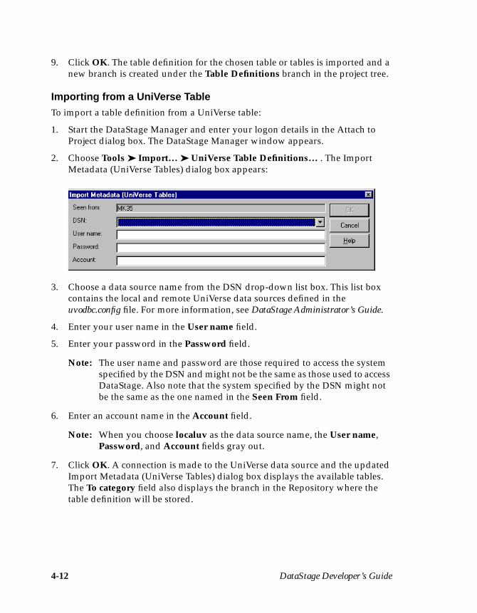
4-12 DataStage Developer’s Guide
9. Click OK. The table definition for the chosen table or tables is imported and anew branch is created under the Table Definitions branch in the project tree.
Importing from a UniVerse TableTo import a table definition from a UniVerse table:
1. Start the DataStage Manager and enter your logon details in the Attach toProject dialog box. The DataStage Manager window appears.
2. Choose Tools ➤ Import… ➤ UniVerse Table Definitions… . The ImportMetadata (UniVerse Tables) dialog box appears:
3. Choose a data source name from the DSN drop-down list box. This list boxcontains the local and remote UniVerse data sources defined in theuvodbc.config file. For more information, see DataStage Administrator’s Guide.
4. Enter your user name in the User name field.
5. Enter your password in the Password field.
Note: The user name and password are those required to access the systemspecified by the DSN and might not be the same as those used to accessDataStage. Also note that the system specified by the DSN might notbe the same as the one named in the Seen From field.
6. Enter an account name in the Account field.
Note: When you choose localuv as the data source name, the User name,Password, and Account fields gray out.
7. Click OK. A connection is made to the UniVerse data source and the updatedImport Metadata (UniVerse Tables) dialog box displays the available tables.The To category field also displays the branch in the Repository where thetable definition will be stored.
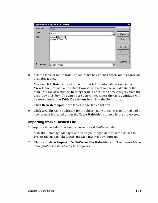
Setting Up a Project 4-13
8. Select a table or tables from the Tables list box or click Select all to choose allavailable tables.
You can click Details… to display further information about each table orView Data… to invoke the Data Browser to examine the actual data in thetable. You can also edit the To category field or choose a new category from thedrop-down list box. The entry here determines where the table definition willbe stored under the Table Definitions branch in the Repository.
Click Refresh to update the tables in the Tables list box.
9. Click OK. The table definition for the chosen table or tables is imported and anew branch is created under the Table Definitions branch in the project tree.
Importing from a Hashed FileTo import a table definition from a hashed (local UniVerse) file:
1. Start the DataStage Manager and enter your logon details in the Attach toProject dialog box. The DataStage Manager window appears.
2. Choose Tools ➤ Import… ➤ UniVerse File Definitions… . The Import Meta-data (UniVerse Files) dialog box appears:
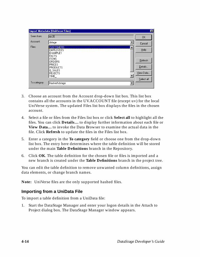
4-14 DataStage Developer’s Guide
3. Choose an account from the Account drop-down list box. This list boxcontains all the accounts in the UV.ACCOUNT file (except uv) for the localUniVerse system. The updated Files list box displays the files in the chosenaccount.
4. Select a file or files from the Files list box or click Select all to highlight all thefiles. You can click Details… to display further information about each file orView Data… to invoke the Data Browser to examine the actual data in thefile. Click Refresh to update the files in the Files list box.
5. Enter a category in the To category field or choose one from the drop-downlist box. The entry here determines where the table definition will be storedunder the main Table Definitions branch in the Repository.
6. Click OK. The table definition for the chosen file or files is imported and anew branch is created under the Table Definitions branch in the project tree.
You can edit the table definition to remove unwanted column definitions, assigndata elements, or change branch names.
Note: UniVerse files are the only supported hashed files.
Importing from a UniData FileTo import a table definition from a UniData file:
1. Start the DataStage Manager and enter your logon details in the Attach toProject dialog box. The DataStage Manager window appears.

Setting Up a Project 4-15
2. Choose Tools ➤ Import… ➤ UniData File Definitions… . The Import Meta-data (Unidata Files) dialog box appears:
3. Enter the name of the host where the UniData files are located in the Serverfield.
4. Enter your user name in the User name field.
5. Enter your password in the Password field.
6. Click the Database drop-down list box to populate it with the names ofUniData databases on that server.
7. Choose a database and click OK. The updated Import Metadata (UnidataFiles) dialog box displays a list of available UniData files and tables.
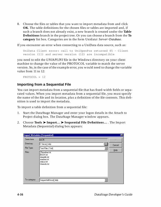
4-16 DataStage Developer’s Guide
8. Choose the files or tables that you want to import metadata from and clickOK. The table definitions for the chosen files or tables are imported and, ifsuch a branch does not already exist, a new branch is created under the TableDefinitions branch in the project tree. Or you can choose a branch from the Tocategory list box. Categories are in the form Unidata\Server>Database.
If you encounter an error when connecting to a UniData data source, such as:
UniData Client error: call to UniOpenPos returned 45 - Clientversion (11) and server version (12) are incompatible
you need to edit the UNIAPI.INI file in the Windows directory on your clientmachine to change the value of the PROTOCOL variable to match the serverversion. So, in the case of the example error, you would need to change the variablevalue from 11 to 12:
PROTOCOL = 12
Importing from a Sequential FileYou can import metadata from a sequential file that has fixed-width fields or sepa-rated values. When you import metadata from a sequential file, you must specifythe name of the file and its location, plus a definition of the file contents. This defi-nition is used to import the metadata.
To import a table definition from a sequential file:
1. Start the DataStage Manager and enter your logon details in the Attach toProject dialog box. The DataStage Manager window appears.
2. Choose Tools ➤ Import… ➤ Sequential File Definitions… . The ImportMetadata (Sequential) dialog box appears:
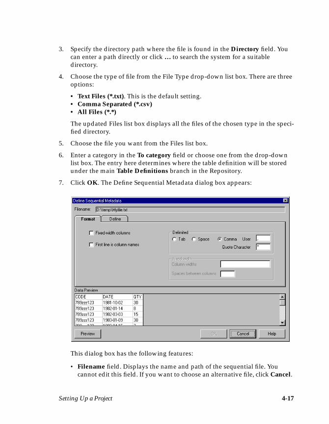
Setting Up a Project 4-17
3. Specify the directory path where the file is found in the Directory field. Youcan enter a path directly or click … to search the system for a suitabledirectory.
4. Choose the type of file from the File Type drop-down list box. There are threeoptions:
• Text Files (*.txt). This is the default setting.• Comma Separated (*.csv)• All Files (*.*)
The updated Files list box displays all the files of the chosen type in the speci-fied directory.
5. Choose the file you want from the Files list box.
6. Enter a category in the To category field or choose one from the drop-downlist box. The entry here determines where the table definition will be storedunder the main Table Definitions branch in the Repository.
7. Click OK. The Define Sequential Metadata dialog box appears:
This dialog box has the following features:
• Filename field. Displays the name and path of the sequential file. Youcannot edit this field. If you want to choose an alternative file, click Cancel.
4-18 DataStage Developer’s Guide
The Import Metadata (Sequential) dialog box reappears and you canspecify a different directory or file.
• Format page. Displayed by default. Contains options that define how thefile is formatted. There are two check boxes on the left of this page:
– Fixed-width columns. Specifies whether the file contains fixed-widthcolumns. The setting for this check box determines the options availableon the rest of the page. When this check box is cleared (the default setting)the options in the Delimited area are available. Select this check box if thefile contains fixed-width columns. You must then use the options in theFixed width area to define the column widths.
– First line is column names. Specifies that the first data row in the filecontains the column names. This check box is cleared by default. Selectthis check box if the first line contains column names.
The rest of this page is divided into two areas:
– Delimited. The options in this area are available only if the Fixed-widthcolumns check box is cleared. The option buttons Tab, Space, andComma (the default) specify how the fields are separated. To specify analternative separation character, enter it in the User field. If values arequoted, enter the quote character in the Quote Character field. You canenter a number from 0 to 255 in the User or Quote Character fields torepresent the ASCII code for the character you want to use.
– Fixed width. The options in this area are available only if the Fixed-widthcolumns check box is selected. Enter the width for each column in theColumn widths field. Widths are entered using the format n,n,n…n,where n is the width of the column. You must have an entry for eachcolumn in the file. Specify the space between the columns by entering avalue in the Spaces between columns field.
• Define page. Displays the column definition for each column in the file. Ifthe first row in the file contains the column names, these are displayed inthe Column name column, otherwise, default column names are assigned.You can edit any of the values in the grid. For more information aboutediting grids, see Appendix B, “Editing Grids.”
• Data Preview grid. This grid displays the first 10 rows of data in the chosenfile using the options specified on the Format page. Click Preview toupdate the Data Preview grid using the format options you selected.
8. Complete the relevant details on the Format page and fine tune the SQL prop-erties on the Define page.
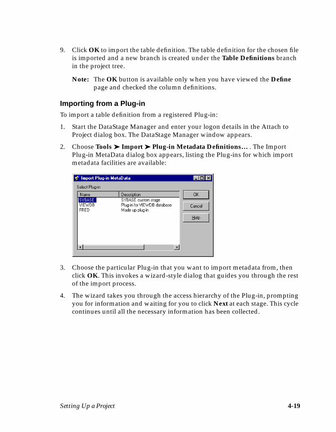
Setting Up a Project 4-19
9. Click OK to import the table definition. The table definition for the chosen fileis imported and a new branch is created under the Table Definitions branchin the project tree.
Note: The OK button is available only when you have viewed the Definepage and checked the column definitions.
Importing from a Plug-inTo import a table definition from a registered Plug-in:
1. Start the DataStage Manager and enter your logon details in the Attach toProject dialog box. The DataStage Manager window appears.
2. Choose Tools ➤ Import ➤ Plug-in Metadata Definitions… . The ImportPlug-in MetaData dialog box appears, listing the Plug-ins for which importmetadata facilities are available:
3. Choose the particular Plug-in that you want to import metadata from, thenclick OK. This invokes a wizard-style dialog that guides you through the restof the import process.
4. The wizard takes you through the access hierarchy of the Plug-in, promptingyou for information and waiting for you to click Next at each stage. This cyclecontinues until all the necessary information has been collected.
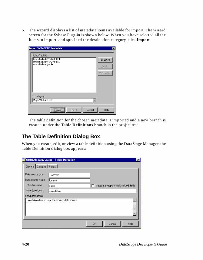
4-20 DataStage Developer’s Guide
5. The wizard displays a list of metadata items available for import. The wizardscreen for the Sybase Plug-in is shown below. When you have selected all theitems to import, and specified the destination category, click Import.
The table definition for the chosen metadata is imported and a new branch iscreated under the Table Definitions branch in the project tree.
The Table Definition Dialog BoxWhen you create, edit, or view a table definition using the DataStage Manager, theTable Definition dialog box appears:
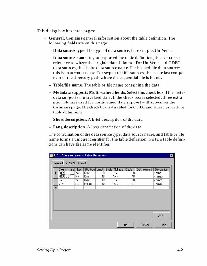
Setting Up a Project 4-21
This dialog box has three pages:
• General. Contains general information about the table definition. Thefollowing fields are on this page:
– Data source type. The type of data source, for example, UniVerse.
– Data source name. If you imported the table definition, this contains areference to where the original data is found. For UniVerse and ODBCdata sources, this is the data source name. For hashed file data sources,this is an account name. For sequential file sources, this is the last compo-nent of the directory path where the sequential file is found.
– Table/file name. The table or file name containing the data.
– Metadata supports Multi-valued fields. Select this check box if the meta-data supports multivalued data. If the check box is selected, three extragrid columns used for multivalued data support will appear on theColumns page. The check box is disabled for ODBC and stored proceduretable definitions.
– Short description. A brief description of the data.
– Long description. A long description of the data.
The combination of the data source type, data source name, and table or filename forms a unique identifier for the table definition. No two table defini-tions can have the same identifier.

4-22 DataStage Developer’s Guide
• Columns. Contains a grid displaying the column definitions for eachcolumn in the table definition. The grid has the following columns:
– Column name. The name of the column.
– Key. Indicates whether the column is part of the primary key.
– SQL type. The SQL data type.
– Length. The data precision. This is the length for CHAR data and themaximum length for VARCHAR data.
– Scale. The data scale factor.
– Nullable. Specifies whether the column can contain null values.
– Display. The maximum number of characters required to display thecolumn data.
– Data element. The type of data in the column.
– Description. A text description of the column.
The following columns appear if you selected the Metadata supportsMulti-valued fields check box on the General page:
– Association. The name of the association (if any) that the column belongsto.
– Position. The field number.
– Type. The nesting type, which can be S, M, MV, or MS.
The Columns page for each link also contains a Load… button. This loads(copies) the column definitions from a table definition elsewhere in theRepository.
A shortcut menu available in grids allows you to edit a cell, delete a row, oradd a row.
For more information about editing a grid, see Appendix B, “EditingGrids.”
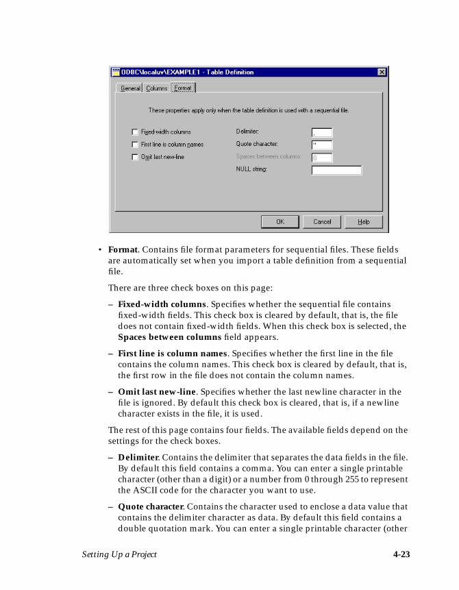
Setting Up a Project 4-23
• Format. Contains file format parameters for sequential files. These fieldsare automatically set when you import a table definition from a sequentialfile.
There are three check boxes on this page:
– Fixed-width columns. Specifies whether the sequential file containsfixed-width fields. This check box is cleared by default, that is, the filedoes not contain fixed-width fields. When this check box is selected, theSpaces between columns field appears.
– First line is column names. Specifies whether the first line in the filecontains the column names. This check box is cleared by default, that is,the first row in the file does not contain the column names.
– Omit last new-line. Specifies whether the last newline character in thefile is ignored. By default this check box is cleared, that is, if a newlinecharacter exists in the file, it is used.
The rest of this page contains four fields. The available fields depend on thesettings for the check boxes.
– Delimiter. Contains the delimiter that separates the data fields in the file.By default this field contains a comma. You can enter a single printablecharacter (other than a digit) or a number from 0 through 255 to representthe ASCII code for the character you want to use.
– Quote character. Contains the character used to enclose a data value thatcontains the delimiter character as data. By default this field contains adouble quotation mark. You can enter a single printable character (other
4-24 DataStage Developer’s Guide
than a digit) or a number from 0 through 255 to represent the ASCII codefor the character you want to use.
– Spaces between columns. Specifies the number of spaces used betweenthe columns in the file. This field appears when you select Fixed-widthcolumns.
– NULL string. Contains characters that are written to the file when acolumn contains SQL null values.
Manually Entering a Table DefinitionIf you are unable to import the table definitions for your source or target data, youmust enter this information manually.
To manually enter table definition properties, you must first create a new tabledefinition. You can then enter suitable settings for the general properties beforespecifying the column definitions. You only need to specify file format settings fora sequential file table definition.
Creating a Table DefinitionTo create a table definition:
1. Start the DataStage Manager and enter your logon details in the Attach toProject dialog box. The DataStage Manager window appears.
2. Select the Table Definitions branch and do one of the following:
• Choose File ➤ New Table Definition… .• Choose New Table Definition… from the shortcut menu.• Click the New icon on the toolbar.
The Table Definition dialog box appears. You must enter suitable values in thefields on the General page.
3. Enter the type of data source in the Data source type field. The name enteredhere determines how the definition will be stored under the Table Defini-tions branch.
4. Enter the name of the data source in the Data source name field. This formsthe second part of the table definition identifier and is the name of the branchcreated under the data source type branch.
5. Enter the name of the table or file containing the data in the Table/file namefield. This is the last part of the table definition identifier and is the name ofthe leaf created under the data source branch.

Setting Up a Project 4-25
6. Select the Metadata supports Multi-valued fields check box if the metadatasupports multivalued data.
7. Enter a brief description of the data in the Short description field. This is anoptional field. The text entered here is displayed when you choose View ➤Details from the DataStage Manager window.
8. Enter a more detailed description of the data in the Long description field.This is an optional field.
9. Click the Columns tab. The Columns page appears at the front of the TableDefinition dialog box. You can now enter or load column definitions for yourdata.
Entering Column DefinitionsYou can enter column definitions directly in the Columns grid. To add a newcolumn definition, you must edit the empty row (indicated by a star) in theColumns grid.
1. Click the first cell in the row (Column name) and enter the name of thecolumn you want to add. This is the minimum requirement for adding a newcolumn definition. You can then click the other cells you want to edit, or pressTab to move between the cells. For more information about adding anddeleting rows, or moving between the cells of a grid, see Appendix B,“Editing Grids.”
2. Specify whether this column is a key column. If it is, choose Y from the drop-down list in the Key cell.
3. Specify the SQL data type by choosing an appropriate type from the drop-down list in the SQL type cell.
4. Enter an appropriate value for the data precision in the Length cell.
5. Enter an appropriate data scale factor in the Scale cell.
6. Specify whether the column can contain null values by choosing an appro-priate option from the drop-down list in the Nullable cell.
7. Enter the maximum number of characters required to display the columndata in the Display cell.
8. Choose the type of data the column contains from the drop-down list in theData element cell. This list contains all the built-in data elements suppliedwith DataStage and any additional data elements you have defined. You donot need to edit this cell to create a column definition. You can assign a dataelement at any point during the development of your job. For more informa-tion, see “Assigning Data Elements” on page 4-40.
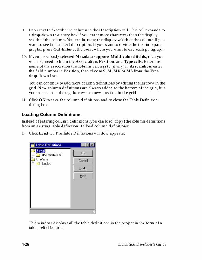
4-26 DataStage Developer’s Guide
9. Enter text to describe the column in the Description cell. This cell expands toa drop-down text entry box if you enter more characters than the displaywidth of the column. You can increase the display width of the column if youwant to see the full text description. If you want to divide the text into para-graphs, press Ctrl-Enter at the point where you want to end each paragraph.
10. If you previously selected Metadata supports Multi-valued fields, then youwill also need to fill in the Association, Position, and Type cells. Enter thename of the association the column belongs to (if any) in Association, enterthe field number in Position, then choose S, M, MV or MS from the Typedrop-down list.
You can continue to add more column definitions by editing the last row in thegrid. New column definitions are always added to the bottom of the grid, butyou can select and drag the row to a new position in the grid.
11. Click OK to save the column definitions and to close the Table Definitiondialog box.
Loading Column DefinitionsInstead of entering column definitions, you can load (copy) the column definitionsfrom an existing table definition. To load column definitions:
1. Click Load… . The Table Definitions window appears:
This window displays all the table definitions in the project in the form of atable definition tree.
Setting Up a Project 4-27
2. Double-click the appropriate branch to display the table definitions available.
3. Select the table definition you want to use.
Note: You can use the Find… button to enter the name of the table definitionyou want. The table definition is automatically highlighted in the treewhen you click OK.
4. Click OK. The column definitions from the chosen table definition are copiedinto your new table definition.
5. Save the table definition by clicking OK.
You can edit the table definition to remove unwanted column definitions, assigndata elements, or change branch names.
Viewing or Modifying a Table DefinitionYou can view or modify any table definition in your project. To view a table defi-nition, select it in the display area and do one of the following:
• Choose File ➤ Properties… .• Choose Properties… from the shortcut menu.• Double-click the table definition in the display area.• Click the Properties icon on the toolbar.
The Table Definition dialog box appears. You can edit any of the column definitionproperties or delete unwanted definitions.
Editing Column DefinitionsTo edit a column definition in the grid, click the cell you want to change. The wayyou edit the cell depends on the cell contents. If the cell contains a drop-down list,choose an alternative option from the drop-down list. If the cell contains text, youcan start typing to change the value, or press F2 or choose Edit cell… from theshortcut menu to put the cell into edit mode.
For more information about adding and deleting rows, or moving between thecells of a grid, see Appendix B, “Editing Grids.”
Deleting Column DefinitionsWhen you import a table definition, all the column definitions in the data table areimported. Also, when you load column definitions, all the column definitions inthe existing table definition are copied.
4-28 DataStage Developer’s Guide
If you do not want to extract the data in a particular column, or do not want towrite data to a particular column in the data mart, you must delete the corre-sponding column definition.
Unwanted column definitions can be easily removed from the Columns grid. Todelete a column definition, click any cell in the row you want to remove and pressthe Delete key or choose Delete row… from the shortcut menu. Click OK to saveany changes and to close the Table Definition dialog box.
To delete several column definitions at once, hold down the Ctrl key and click inthe row selector column for the rows you want to remove. Press the Delete key orchoose Delete row… from the shortcut menu to remove the selected rows.
Using the Data BrowserWhen importing table definitions from a data source, you can view the actual datain the tables using the Data Browser. The Data Browser can be used whenimporting table definitions from the following sources:
• ODBC table• UniVerse table• Hashed (UniVerse) file• UniData file• Some types of Plug-in
Note: Sequential files can be viewed through standard Windows tools, such asWordPad.
The Data Browser is invoked by clicking the View Data… button on the ImportMetadata dialog box. The Data Browser window appears:
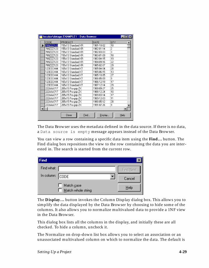
Setting Up a Project 4-29
The Data Browser uses the metadata defined in the data source. If there is no data,a Data source is empty message appears instead of the Data Browser.
You can view a row containing a specific data item using the Find… button. TheFind dialog box repositions the view to the row containing the data you are inter-ested in. The search is started from the current row.
The Display… button invokes the Column Display dialog box. This allows you tosimplify the data displayed by the Data Browser by choosing to hide some of thecolumns. It also allows you to normalize multivalued data to provide a 1NF viewin the Data Browser.
This dialog box lists all the columns in the display, and initially these are allchecked. To hide a column, uncheck it.
The Normalize on drop-down list box allows you to select an association or anunassociated multivalued column on which to normalize the data. The default is

4-30 DataStage Developer’s Guide
Un-Normalized, and choosing Un-Normalized will display the data in NF2 formwith each row shown on a single line. Alternatively you can select Un-Normalize(formatted), which displays multivalued rows split over several lines.
In the example, the Data Browser would display all columns except TaxRate. Theview would be normalized on the association Assoc1.
Stored Procedure DefinitionsIf you are accessing data from or writing data to a database via an ODBC connec-tion, you can use a stored procedure to define the data to use. A stored procedurecan:
• Have associated parameters, which may be input or output• Return a value (like a function call)• Create a result set in the same way as an SQL SELECT statement
Note: DataStage supports the use of stored procedures with or without inputarguments and the creation of a result set, but does not support outputarguments or return values. A stored procedure may have a return valuedefined, but it is ignored at run time. A stored procedure may not haveoutput parameters.
The definition for a stored procedure (including the associated parameters andmetadata) can be stored in the Repository. These stored procedure definitions canbe used when you edit an ODBC or UniVerse stage in your job design. For moreinformation about developing a job, see Chapter 5, “Developing a Job.” For more
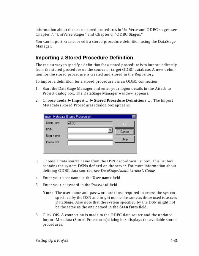
Setting Up a Project 4-31
information about the use of stored procedures in UniVerse and ODBC stages, seeChapter 7, “UniVerse Stages” and Chapter 6, “ODBC Stages.”
You can import, create, or edit a stored procedure definition using the DataStageManager.
Importing a Stored Procedure DefinitionThe easiest way to specify a definition for a stored procedure is to import it directlyfrom the stored procedure on the source or target ODBC database. A new defini-tion for the stored procedure is created and stored in the Repository.
To import a definition for a stored procedure via an ODBC connection:
1. Start the DataStage Manager and enter your logon details in the Attach toProject dialog box. The DataStage Manager window appears.
2. Choose Tools ➤ Import… ➤ Stored Procedure Definitions… . The ImportMetadata (Stored Procedures) dialog box appears:
3. Choose a data source name from the DSN drop-down list box. This list boxcontains the system DSNs defined on the server. For more information aboutdefining ODBC data sources, see DataStage Administrator’s Guide.
4. Enter your user name in the User name field.
5. Enter your password in the Password field.
Note: The user name and password are those required to access the systemspecified by the DSN and might not be the same as those used to accessDataStage. Also note that the system specified by the DSN might notbe the same as the one named in the Seen from field.
6. Click OK. A connection is made to the ODBC data source and the updatedImport Metadata (Stored Procedures) dialog box displays the available storedprocedures:
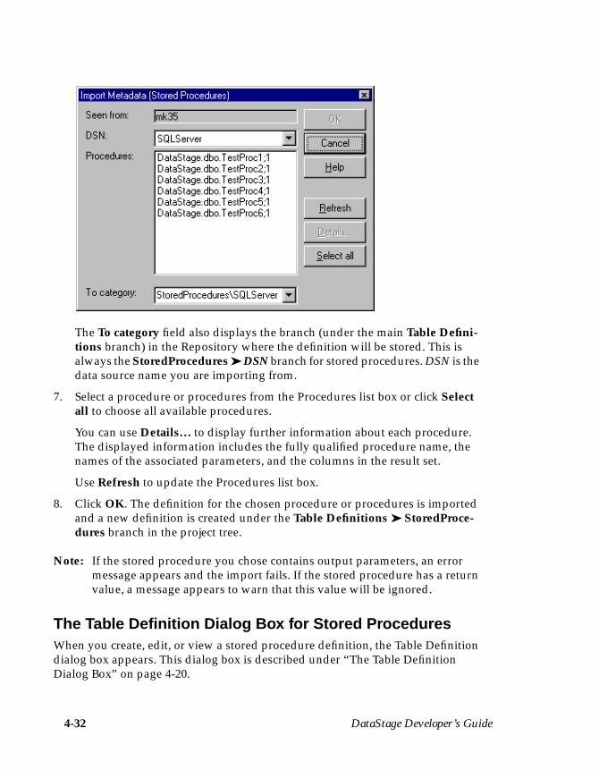
4-32 DataStage Developer’s Guide
The To category field also displays the branch (under the main Table Defini-tions branch) in the Repository where the definition will be stored. This isalways the StoredProcedures ➤ DSN branch for stored procedures. DSN is thedata source name you are importing from.
7. Select a procedure or procedures from the Procedures list box or click Selectall to choose all available procedures.
You can use Details… to display further information about each procedure.The displayed information includes the fully qualified procedure name, thenames of the associated parameters, and the columns in the result set.
Use Refresh to update the Procedures list box.
8. Click OK. The definition for the chosen procedure or procedures is importedand a new definition is created under the Table Definitions ➤ StoredProce-dures branch in the project tree.
Note: If the stored procedure you chose contains output parameters, an errormessage appears and the import fails. If the stored procedure has a returnvalue, a message appears to warn that this value will be ignored.
The Table Definition Dialog Box for Stored ProceduresWhen you create, edit, or view a stored procedure definition, the Table Definitiondialog box appears. This dialog box is described under “The Table DefinitionDialog Box” on page 4-20.
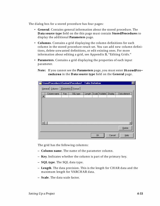
Setting Up a Project 4-33
The dialog box for a stored procedure has four pages:
• General. Contains general information about the stored procedure. TheData source type field on the this page must contain StoredProcedures todisplay the additional Parameters page.
• Columns. Contains a grid displaying the column definitions for eachcolumn in the stored procedure result set. You can add new column defini-tions, delete unwanted definitions, or edit existing ones. For moreinformation about editing a grid, see Appendix B, “Editing Grids.”
• Parameters. Contains a grid displaying the properties of each inputparameter.
Note: If you cannot see the Parameters page, you must enter StoredPro-cedures in the Data source type field on the General page.
The grid has the following columns:
– Column name. The name of the parameter column.
– Key. Indicates whether the column is part of the primary key.
– SQL type. The SQL data type.
– Length. The data precision. This is the length for CHAR data and themaximum length for VARCHAR data.
– Scale. The data scale factor.
4-34 DataStage Developer’s Guide
– Nullable. Specifies whether the column can contain null values.
– Display. The maximum number of characters required to display thecolumn data.
– Data element. The type of data in the column.
– Description. A text description of the column.
• Format. Contains file format parameters for sequential files. This page isnot used for a stored procedure definition.
Manually Entering a Stored Procedure DefinitionIf you are unable to import the definition for your stored procedure, you mustenter this information manually.
To manually enter a stored procedure definition, first create the definition usingthe DataStage Manager. You can then enter suitable settings for the general prop-erties, before specifying definitions for the columns in the result set and the inputparameters.
Note: You do not need to edit the Format page for a stored procedure definition.
Creating a Stored Procedure DefinitionTo create a stored procedure definition:
1. Start the DataStage Manager and enter your logon details in the Attach toProject dialog box. The DataStage Manager window appears.
2. Select the Table Definitions branch and do one of the following:
• Choose File ➤ New Table Definition… .• Choose New Table Definition… from the shortcut menu.• Click the New icon on the toolbar.
The Table Definition dialog box appears. You must enter suitable values in thefields on the General page.
3. Enter StoredProcedures in the Data source type field. This specifies thatthe new definition will be stored under the Table Definitions ➤ StoredProce-dures branch in the Repository. The Parameters page appears in the TableDefinition dialog box.
4. Enter the name of the data source in the Data source name field. This formsthe second part of the table definition identifier and is the name of the branchcreated under the data source type branch.
Setting Up a Project 4-35
5. Enter the name of the procedure in the Procedure name field. This is the lastpart of the table definition identifier and is the name of the leaf created underthe data source branch.
6. Enter a brief description of the data in the Short description field. This is anoptional field. The text entered here is displayed when you choose View ➤Details from the DataStage Manager window.
7. Enter a detailed description of the data in the Long description field.
8. Specify the column definitions for the result set on the Columns page and theinput parameters (if any) for the stored procedure on the Parameters page.
Specifying Column Definitions for the Result SetTo specify the column definitions for the result set, click the Columns tab in theTable Definition dialog box. The Columns page appears at the front of the TableDefinition dialog box. You can now enter or load column definitions. For moreinformation, see “Entering Column Definitions” on page 4-25 and “LoadingColumn Definitions” on page 4-26.
Note: You do not need a result set if the stored procedure is used for input(writing to a database). However, in this case, you must have inputparameters.
Specifying Input ParametersTo specify input parameters for the stored procedure, click the Parameters tab inthe Table Definition dialog box. The Parameters page appears at the front of theTable Definition dialog box.
Parameter definitions are entered directly in the Parameters grid. To add a newparameter definition, you must edit the empty row (indicated by a star) in theParameters grid:
1. Click the first cell in the row (Column name) and enter the name of theparameter you want to add. This is the minimum requirement for adding anew parameter definition. Click the other cells you want to edit, or press Tabto move between the cells. For more information about adding and deletingrows, or moving between the cells of a grid, see Appendix B, “Editing Grids.”
2. Specify the SQL data type by choosing an appropriate type from the drop-down list in the SQL type cell.
3. Enter an appropriate value for the data precision in the Length cell.
4. Enter an appropriate data scale factor in the Scale cell.
4-36 DataStage Developer’s Guide
5. Specify whether the parameter can contain null values by choosing an appro-priate option from the drop-down list in the Nullable cell.
6. Enter the maximum number of characters required to display the parameterdata in the Display cell.
7. Choose the type of data the column contains from the drop-down list in theData element cell. This list contains all the built-in data elements suppliedwith DataStage and any additional data elements you have defined. You donot need to edit this cell to create a column definition. You can assign a dataelement at any point during the development of your job. For more informa-tion, see “Assigning Data Elements” on page 4-40.
8. Enter text to describe the column in the Description cell. This cell expands toa drop-down text entry box if you enter more characters than the displaywidth of the column. You can increase the display width of the column if youwant to see the full text description.
You can continue to add more parameter definitions by editing the last row inthe grid. New parameters are always added to the bottom of the grid, but youcan select and drag the row to a new position in the grid.
9. Click OK to save and close the Table Definition dialog box.
Viewing or Modifying a Stored Procedure DefinitionYou can view or modify any stored procedure definition in your project. To view astored procedure definition, select it in the display area and do one of thefollowing:
• Choose File ➤ Properties… .• Choose Properties… from the shortcut menu.• Double-click the stored procedure definition in the display area.• Click the Properties icon on the toolbar.
The Table Definition dialog box appears. You can edit or delete any of the columnor parameter definitions.
Editing Column or Parameter DefinitionsYou can edit the settings for a column or parameter definition by editing directlyin the Columns or Parameters grid. To edit a definition, click the cell you want tochange. The way you edit the cell depends on the cell contents. If the cell containsa drop-down list, choose an alternative option from the drop-down list. If the cellcontains text, you can start typing to change the value, or press F2 or choose Editcell… from the shortcut menu to put the cell into edit mode.
Setting Up a Project 4-37
For more information about adding and deleting rows, or moving between thecells of a grid, see Appendix B, “Editing Grids.”
Deleting Column or Parameter DefinitionsWhen you import a stored procedure definition, all the column definitions speci-fied for the result set are imported. Also, when you load column definitions, all thecolumn definitions in the existing table definition are copied.
If you do not want to extract or write the data in a particular column or use a partic-ular input parameter, you must delete the corresponding definition.
Unwanted column or parameter definitions can be easily removed from theColumns or Parameters grid. To delete a column or parameter definition, click anycell in the row you want to remove and press the Delete key or choose Deleterow… from the shortcut menu. Click OK to save any changes and to close the TableDefinition dialog box.
To delete several column or parameter definitions at once, hold down the Ctrl keyand click in the row selector column for the rows you want to remove. Press theDelete key or choose Delete row… from the shortcut menu to remove the selectedrows.
Data ElementsEach column definition may have a data element assigned to it. A data element spec-ifies the type of data a column contains, which in turn determines the transformsthat can be applied in a Transformer stage.
You can choose to use any of the data elements supplied with DataStage, or youcan create and use data elements specific to your application. For a list of the built-in data elements available, see “Built-in Data Elements” on page 4-42.
Application-specific data elements allow you to describe the data in a particularcolumn in more detail. The more information you supply to DataStage about yourdata, the more DataStage can help to define the processing needed in each Trans-former stage.
For example, if you have a column containing a numeric product code, you mightassign it the built-in data element Number. There is a range of built-in transformsassociated with this data element. However, all of these would be unsuitable, as itis unlikely that you would want to perform a calculation on a product code. In thiscase, you could create a new data element called PCode.
4-38 DataStage Developer’s Guide
Each data element has its own specific set of transforms which relate it to otherdata elements. When the data elements associated with the columns of a targettable are not the same as the data elements of the source data, you must ensure thatyou have the transforms needed to convert the data as required. For each targetcolumn, you should have either a source column with the same data element, or asource column that you can convert to the required data element.
For example, suppose that the target table requires a product code using the dataelement PCode, but the source table holds product data using an older productnumbering scheme. In this case, you could create a separate data element for old-format product codes called Old_PCode, and you then create a custom transformto link the two data elements; that is, its source data element is Old_PCode, whileits target data element is PCode. This transform, which you could callConvert_PCode, would convert an old product code to a new product code. See“Transforms” on page 11-14 for details on how to use and create customtransforms.
A data element can also be used to “stamp” a column with SQL properties whenyou manually create a table definition or define a column definition for a link in ajob. For details on how to edit the column definition for a link, see “EditingColumn Definitions” on page 5-19.
Creating Data ElementsTo create a data element:
1. Start the DataStage Manager and enter your logon details in the Attach toProject dialog box. The DataStage Manager window appears.
2. Select the Data Elements branch in the project tree and do one of thefollowing:
• Choose File ➤ New Data Element… .• Choose New Data Element… from the shortcut menu.• Click the New icon on the toolbar.
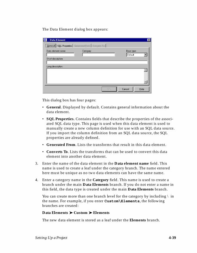
Setting Up a Project 4-39
The Data Element dialog box appears:
This dialog box has four pages:
• General. Displayed by default. Contains general information about thedata element.
• SQL Properties. Contains fields that describe the properties of the associ-ated SQL data type. This page is used when this data element is used tomanually create a new column definition for use with an SQL data source.If you import the column definition from an SQL data source, the SQLproperties are already defined.
• Generated From. Lists the transforms that result in this data element.
• Converts To. Lists the transforms that can be used to convert this dataelement into another data element.
3. Enter the name of the data element in the Data element name field. Thisname is used to create a leaf under the category branch. The name enteredhere must be unique as no two data elements can have the same name.
4. Enter a category name in the Category field. This name is used to create abranch under the main Data Elements branch. If you do not enter a name inthis field, the data type is created under the main Data Elements branch.
You can create more than one branch level for the category by including \ inthe name. For example, if you enter Custom\Elements , the followingbranches are created:
Data Elements ➤ Custom ➤ Elements
The new data element is stored as a leaf under the Elements branch.
4-40 DataStage Developer’s Guide
5. Choose the most appropriate base data type from the Base type drop-downlist box. The base types are the fundamental data types used internally byDataStage for processing.
There are five base types:
• Date. The column contains a date, represented in DataStage internalformat. There are many built-in transforms available to convert dates tocharacter strings. See Appendix A, “Built-in Transforms and Routines,” fora list of the built-in transforms available.
• Number. The column contains a numeric value.
• String. The column contains data as a string of characters. DataStage inter-prets the string as a number if needed.
• Time. The column contains data as a time.
• Default. The data has an SQL data type already assigned and the mostappropriate base type is used.
6. Enter a brief description of the data in the Short description field. This is anoptional field. The text entered here is displayed when you choose View ➤Details from the DataStage Manager window or print a data elements report.
7. Enter a detailed description of the data in the Long description field. This isan optional field. This description is displayed only when you view the prop-erties of a data element.
8. Click OK to save the data element and to close the Data Element dialog box.You must edit your table definition to assign this new data element.
Assigning Data ElementsIf you created a new data element or you want to use one of the data elementssupplied with DataStage, you need to assign it. Data elements are assigned byediting the column definitions. If you want to set up the data elements before youdevelop your job, you can edit the column definitions in the table definition.
To assign a data element:
1. Start the DataStage Manager and enter your project details in the Attach toProject dialog box. The DataStage Manager window appears.
2. Expand the Table Definitions branch until you can see the table definitionyou want to edit in the display area.
Setting Up a Project 4-41
3. Select the table definition and do one of the following:
• Choose File ➤ Properties… .• Choose Properties… from the shortcut menu.• Double-click the table definition in the display area.• Click the Properties icon on the toolbar.
The Table Definition dialog box appears.
4. Click the Columns tab. The Columns page appears at the front of the TableDefinition dialog box.
5. Click the Data element cell for the column definition you want to edit.
6. Choose the data element you want to use from the drop-down list. This listcontains all the built-in data elements supplied with DataStage and any dataelements you created. For a description of the built-in data elements suppliedwith DataStage, see “Built-in Data Elements” on page 4-42.
7. Click OK to save the column definition and to close the Table Definitiondialog box.
Note: You can assign data elements at any point during the development of yourjob. For details on how to edit column definitions, see “Editing ColumnDefinitions” on page 5-19.
Viewing or Editing Data ElementsYou can view the properties of any data element in your project. To view the prop-erties of a data element, select it in the display area and do one of the following:
• Choose File ➤ Properties… .• Choose Properties… from the shortcut menu.• Double-click the data element in the display area.• Click the Properties icon on the toolbar.
The Data Element dialog box appears. Click OK to close the dialog box.
If you are viewing the properties of a data element that you created, you can editany of the fields on the General or SQL Properties page. The changes are savedwhen you click OK.
If you are viewing the properties of a built-in data element, you cannot edit any ofthe settings on the General or SQL Properties page.
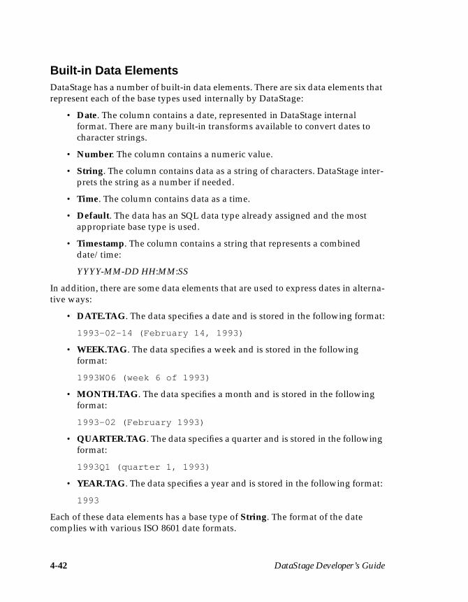
4-42 DataStage Developer’s Guide
Built-in Data ElementsDataStage has a number of built-in data elements. There are six data elements thatrepresent each of the base types used internally by DataStage:
• Date. The column contains a date, represented in DataStage internalformat. There are many built-in transforms available to convert dates tocharacter strings.
• Number. The column contains a numeric value.
• String. The column contains data as a string of characters. DataStage inter-prets the string as a number if needed.
• Time. The column contains data as a time.
• Default. The data has an SQL data type already assigned and the mostappropriate base type is used.
• Timestamp. The column contains a string that represents a combineddate/time:
YYYY-MM-DD HH:MM:SS
In addition, there are some data elements that are used to express dates in alterna-tive ways:
• DATE.TAG. The data specifies a date and is stored in the following format:
1993-02-14 (February 14, 1993)
• WEEK.TAG. The data specifies a week and is stored in the followingformat:
1993W06 (week 6 of 1993)
• MONTH.TAG. The data specifies a month and is stored in the followingformat:
1993-02 (February 1993)
• QUARTER.TAG. The data specifies a quarter and is stored in the followingformat:
1993Q1 (quarter 1, 1993)
• YEAR.TAG. The data specifies a year and is stored in the following format:
1993
Each of these data elements has a base type of String. The format of the datecomplies with various ISO 8601 date formats.
Setting Up a Project 4-43
You can view the properties of these data elements. You cannot edit them.
External ActiveX (OLE) FunctionsDataStage provides you with the ability to call external ActiveX (OLE) functionswhich have been installed on the DataStage server. These functions can then beused when you define custom transforms.
To use this facility, you need an automation server that exposes functions via theIDispatch interface and which has an associated type library. This can be achievedvia a number of development tools, including Visual Basic.
The first step in using external functions is importing them into the DataStageRepository. The action of importing an external function creates a DataStageroutine containing code which calls the external function. The code uses aDataStage BASIC function that accepts only certain data types. These data typesare defined in the DSOLETYPES.H file in the dsinclude directory for each projectand are listed in the DataStage Developer’s Help.
Once imported, you can then call the functions when you define a customtransform.
Note that this facility is only available on Windows NT servers.
Importing External ActiveX (OLE) FunctionsTo import ActiveX (OLE) functions:
1. Start the DataStage Manager and enter your logon details in the Attach toProject dialog box. The DataStage Manager window appears.
2. Choose Tools ➤ Import ➤ External Function Definitions. The Import Trans-form Functions Definitions Wizard appears and prompts you to supply thepathname of the file containing the transforms to be imported. This willnormally be a DLL file and must have already been installed on the servermachine.
3. Enter or browse for the pathname, then click Next. The wizard queries thespecified DLL file to establish what automation classes it contains andpresents these in a drop-down list.
4. Select an automation class and click Next. The wizard interrogates the auto-mation class to obtain details of the suitable functions it supports. It thendisplays these.

4-44 DataStage Developer’s Guide
5. Select the functions that you want to import and specify the Repository cate-gory under which the functions will appear (the default is Routines ➤ classname). Click Next. The wizard displays the details of the proposed import.
6. If you are happy with the details, click Import. DataStage starts to generatethe required routines and displays a progress bar. On completion a summaryscreen appears.
7. Click Finish to exit the wizard.

Developing a Job 5-1
5Developing a Job
This chapter describes the DataStage Designer, DataStage stages, how to developa job, and how to specify job properties.
A DataStage job populates one or more tables in the target database. There is nolimit to the number of jobs you can create in a DataStage project.
Jobs are designed and developed using the DataStage Designer. A job designcontains:
• Stages to represent the processing steps required• Links between the stages to represent the flow of data
Before you start to develop your job, you must plan and set up your project. Thisis described in Chapter 4, “Setting Up a Project.”
Note: If you want to use the reporting tool described in Chapter 18, “Reportingand Printing,” you should ensure that the names of your DataStage compo-nents (jobs, stage, links etc.) do not exceed 64 characters.
The DataStage DesignerThe DataStage Designer is installed by default in the Ardent DataStage programfolder in the Windows Program Manager.
Starting the DataStage DesignerTo start the DataStage Designer, choose Start ➤ Programs ➤ Ardent DataStage ➤DataStage Designer.
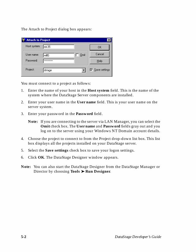
5-2 DataStage Developer’s Guide
The Attach to Project dialog box appears:
You must connect to a project as follows:
1. Enter the name of your host in the Host system field. This is the name of thesystem where the DataStage Server components are installed.
2. Enter your user name in the User name field. This is your user name on theserver system.
3. Enter your password in the Password field.
Note: If you are connecting to the server via LAN Manager, you can select theOmit check box. The User name and Password fields gray out and youlog on to the server using your Windows NT Domain account details.
4. Choose the project to connect to from the Project drop-down list box. This listbox displays all the projects installed on your DataStage server.
5. Select the Save settings check box to save your logon settings.
6. Click OK. The DataStage Designer window appears.
Note: You can also start the DataStage Designer from the DataStage Manager orDirector by choosing Tools ➤ Run Designer.
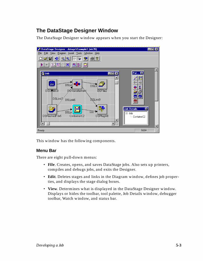
Developing a Job 5-3
The DataStage Designer WindowThe DataStage Designer window appears when you start the Designer:
This window has the following components.
Menu BarThere are eight pull-down menus:
• File. Creates, opens, and saves DataStage jobs. Also sets up printers,compiles and debugs jobs, and exits the Designer.
• Edit. Deletes stages and links in the Diagram window, defines job proper-ties, and displays the stage dialog boxes.
• View. Determines what is displayed in the DataStage Designer window.Displays or hides the toolbar, tool palette, Job Details window, debuggertoolbar, Watch window, and status bar.
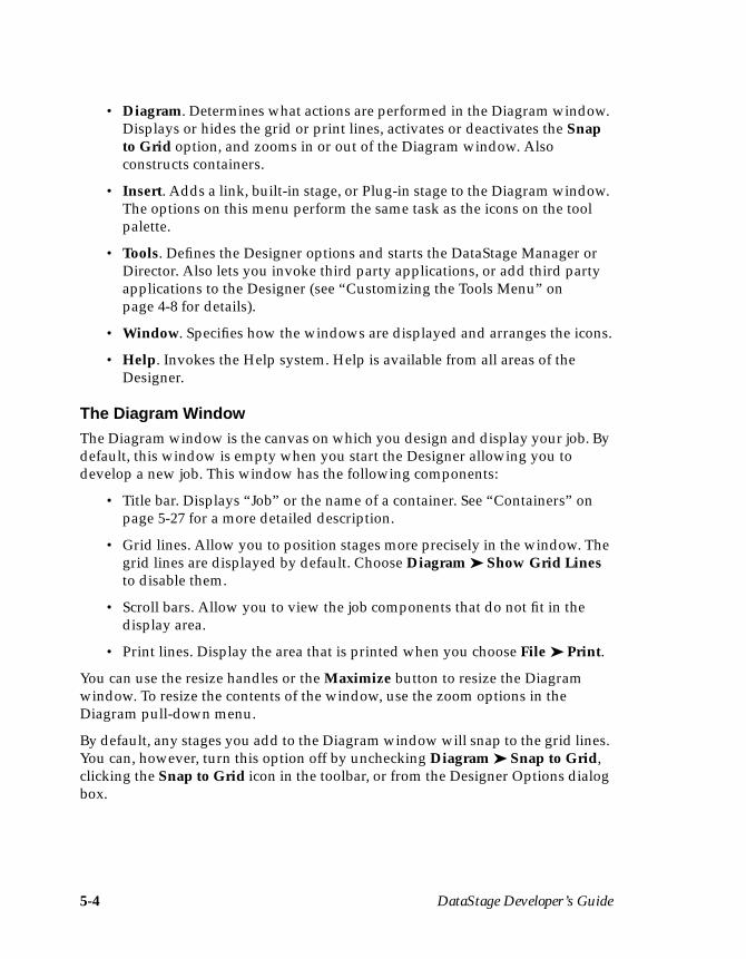
5-4 DataStage Developer’s Guide
• Diagram. Determines what actions are performed in the Diagram window.Displays or hides the grid or print lines, activates or deactivates the Snapto Grid option, and zooms in or out of the Diagram window. Alsoconstructs containers.
• Insert. Adds a link, built-in stage, or Plug-in stage to the Diagram window.The options on this menu perform the same task as the icons on the toolpalette.
• Tools. Defines the Designer options and starts the DataStage Manager orDirector. Also lets you invoke third party applications, or add third partyapplications to the Designer (see “Customizing the Tools Menu” onpage 4-8 for details).
• Window. Specifies how the windows are displayed and arranges the icons.
• Help. Invokes the Help system. Help is available from all areas of theDesigner.
The Diagram WindowThe Diagram window is the canvas on which you design and display your job. Bydefault, this window is empty when you start the Designer allowing you todevelop a new job. This window has the following components:
• Title bar. Displays “Job” or the name of a container. See “Containers” onpage 5-27 for a more detailed description.
• Grid lines. Allow you to position stages more precisely in the window. Thegrid lines are displayed by default. Choose Diagram ➤ Show Grid Linesto disable them.
• Scroll bars. Allow you to view the job components that do not fit in thedisplay area.
• Print lines. Display the area that is printed when you choose File ➤ Print.
You can use the resize handles or the Maximize button to resize the Diagramwindow. To resize the contents of the window, use the zoom options in theDiagram pull-down menu.
By default, any stages you add to the Diagram window will snap to the grid lines.You can, however, turn this option off by unchecking Diagram ➤ Snap to Grid,clicking the Snap to Grid icon in the toolbar, or from the Designer Options dialogbox.

Developing a Job 5-5
ToolbarThe toolbar contains the following icons:
The toolbar appears under the menu bar by default, but you can drag and drop itanywhere on the screen. If you move the toolbar to the edge of the DataStageDesigner window, it attaches to the side of the window. Alternatively, you can hidethe toolbar by choosing View ➤ Toolbar.
Tool PaletteThe tool palette contains icons that represent the components you can add to yourjob design:
Help
Plug-in Stage
Grid Lines
Snap to GridZoom In
Zoom OutSave
CompileOpen Job
New Job
Container Output
Aggregator Stage
Sequential File Stage
Stage
Link
Container InputStage
Hashed File Stage
Transformer Stage
Container Stage
ODBC Stage UniVerse Stage
UniData Stage

5-6 DataStage Developer’s Guide
To add a stage to the Diagram window, choose it from the tool palette and click theDiagram window. The stage is added at the insertion point in the Diagramwindow.
To link two stages, choose the Link icon. Click the first stage, then drag the mouseto the second stage. The stages are linked when you release the mouse button.
The tool palette appears in the DataStage Designer window by default, but you canmove it anywhere on the screen. You can hide the tool palette by choosing View ➤Palette.
The Job Details WindowThe Job Details window appears when you choose View ➤ Job Details. If you areusing containers in your job design, it lists the containers that make up the job.
Double-click the name of a container in the list to display the component stages ina Diagram window. If you choose a container from the list which is alreadydisplayed in a Diagram window, the window appears at the front of the screen.
The Job Details window appears by default in the DataStage Designer window, butyou can move it anywhere on the screen. You can hide the Job Details window bychoosing View ➤ Job Details again.
Status BarThe status bar appears at the bottom of the DataStage Designer window. Itdisplays one-line help for the window components and information on the currentstate of job operations, for example, compilation. You can hide the status bar bychoosing View ➤ Status Bar.
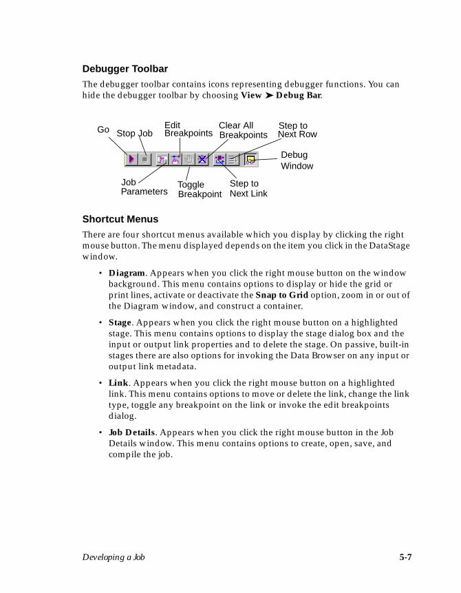
Developing a Job 5-7
Debugger ToolbarThe debugger toolbar contains icons representing debugger functions. You canhide the debugger toolbar by choosing View ➤ Debug Bar.
Shortcut MenusThere are four shortcut menus available which you display by clicking the rightmouse button. The menu displayed depends on the item you click in the DataStagewindow.
• Diagram. Appears when you click the right mouse button on the windowbackground. This menu contains options to display or hide the grid orprint lines, activate or deactivate the Snap to Grid option, zoom in or out ofthe Diagram window, and construct a container.
• Stage. Appears when you click the right mouse button on a highlightedstage. This menu contains options to display the stage dialog box and theinput or output link properties and to delete the stage. On passive, built-instages there are also options for invoking the Data Browser on any input oroutput link metadata.
• Link. Appears when you click the right mouse button on a highlightedlink. This menu contains options to move or delete the link, change the linktype, toggle any breakpoint on the link or invoke the edit breakpointsdialog.
• Job Details. Appears when you click the right mouse button in the JobDetails window. This menu contains options to create, open, save, andcompile the job.
Go Stop Job
Job
Edit
ToggleParameters Breakpoint
BreakpointsClear AllBreakpoints
Step toNext Link
Step toNext Row
DebugWindow
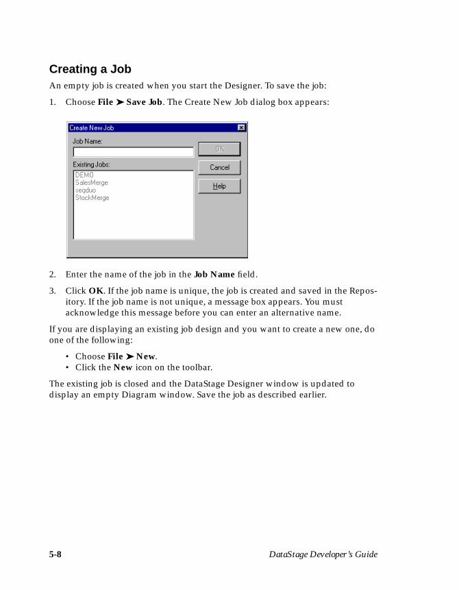
5-8 DataStage Developer’s Guide
Creating a JobAn empty job is created when you start the Designer. To save the job:
1. Choose File ➤ Save Job. The Create New Job dialog box appears:
2. Enter the name of the job in the Job Name field.
3. Click OK. If the job name is unique, the job is created and saved in the Repos-itory. If the job name is not unique, a message box appears. You mustacknowledge this message before you can enter an alternative name.
If you are displaying an existing job design and you want to create a new one, doone of the following:
• Choose File ➤ New.• Click the New icon on the toolbar.
The existing job is closed and the DataStage Designer window is updated todisplay an empty Diagram window. Save the job as described earlier.
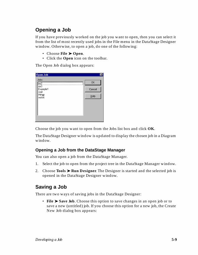
Developing a Job 5-9
Opening a JobIf you have previously worked on the job you want to open, then you can select itfrom the list of most recently used jobs in the File menu in the DataStage Designerwindow. Otherwise, to open a job, do one of the following:
• Choose File ➤ Open.• Click the Open icon on the toolbar.
The Open Job dialog box appears:
Choose the job you want to open from the Jobs list box and click OK.
The DataStage Designer window is updated to display the chosen job in a Diagramwindow.
Opening a Job from the DataStage ManagerYou can also open a job from the DataStage Manager.
1. Select the job to open from the project tree in the DataStage Manager window.
2. Choose Tools ➤ Run Designer. The Designer is started and the selected job isopened in the DataStage Designer window.
Saving a JobThere are two ways of saving jobs in the DataStage Designer:
• File ➤ Save Job. Choose this option to save changes in an open job or tosave a new (untitled) job. If you choose this option for a new job, the CreateNew Job dialog box appears:
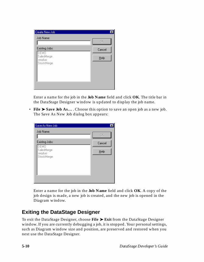
5-10 DataStage Developer’s Guide
Enter a name for the job in the Job Name field and click OK. The title bar inthe DataStage Designer window is updated to display the job name.
• File ➤ Save Job As… . Choose this option to save an open job as a new job.The Save As New Job dialog box appears:
Enter a name for the job in the Job Name field and click OK. A copy of thejob design is made, a new job is created, and the new job is opened in theDiagram window.
Exiting the DataStage DesignerTo exit the DataStage Designer, choose File ➤ Exit from the DataStage Designerwindow. If you are currently debugging a job, it is stopped. Your personal settings,such as Diagram window size and position, are preserved and restored when younext use the DataStage Designer.
Developing a Job 5-11
StagesA job consists of stages linked together which describe the flow of data from a datasource to a final data warehouse. A stage usually has at least one data input andone data output. However, some stages can accept more than one data input, andoutput to more than one stage.
DataStage has several built-in stage types that are used to represent data sources,data marts, or conversion stages. These stages are either Passive or Active stages.A Passive stage handles access to databases for the extraction or writing of data.Active stages model the flow of data and provide mechanisms for combining datastreams, aggregating data, and converting data from one data type to another.
As well as using the built-in stage types, you can also use Plug-in stages for specificoperations that the built-in stages do not support.
Stages and links can be grouped together to form a container. A container is repre-sented by a Container stage. The links to and from a container are represented byContainer Input and Container Output stages.
Each stage type has a set of predefined and editable properties. These propertiesare viewed or edited using stage editors. A stage editor exists for each stage typeand these are described in detail in individual chapters.
At this point in your job development you need to decide which stage types to usein your job design.
Built-in StagesThese are the following built-in stage types:
• Aggregator. Classifies incoming data into groups, computes totals andother summary functions for each group, and passes them to another stagein the job. This is an active stage.
• Hashed File. Extracts data from or loads data into databases that containhashed files. Also acts as an intermediate stage for quick lookups. This is apassive stage.
• ODBC. Extracts data from or loads data into databases that support theindustry standard Open Database Connectivity API. This stage is also usedas an intermediate stage for aggregating data. This is a passive stage.
• UniVerse. Extracts data from or loads data into UniVerse databases. Thisstage is also used as an intermediate stage for aggregating data. This is apassive stage.
5-12 DataStage Developer’s Guide
• UniData. Extracts data from or loads data into UniData databases. This is apassive stage.
• Sequential File. Extracts data from, or loads data into, operating systemtext files. This is a passive stage.
• Transformer. Receives incoming data, transforms it in a variety of ways,and outputs it to another stage in the job. This is an active stage.
• Container. Represents a group of stages and links. The group is replaced bya single Container stage in the Diagram window.
• Container Input and Output. Represent the interface that links a containerstage to the rest of the job design.
Containers, Container stages, and Input and Output stages are described under“Containers” on page 5-27.
Plug-in StagesYou may find that the built-in stage types do not meet all your requirements fordata extraction or transformation. In this case, you need to use a Plug-in stage. Thefunction and properties of a Plug-in stage are determined by the particular Plug-in specified when the stage is inserted. Plug-ins are written to perform specifictasks, for example, to bulk load data into a data mart.
There are two Plug-ins installed with DataStage: the BCPLoad Plug-in and theOrabulk Plug-in. These are described in Chapter 14 and Chapter 15 respectively. Arange of other Plug-ins are supplied with DataStage for you to install if required.Alternatively, you can write your own Plug-ins. For more information, seeChapter 13.
Developing the Job DesignJobs are designed and developed in the Diagram window. Stages are added andlinked together using the tool palette. You can add, move, rename, delete, link, oredit stages in a job design.
Adding StagesThere is no limit to the number of stages you can add to a job. We recommend youposition the stages as follows in the Diagram window:
• Data sources on the left• Data warehouse on the right• Transformer stages in the middle of the diagram

Developing a Job 5-13
Add a stage for each data source and one for the final data mart. Add Transformerstages to convert incoming data and to output the result to another stage in the job.To add a stage:
1. Do one of the following:
• Choose the stage from the Insert menu.• Click the stage icon on the tool palette.
2. Click in the Diagram window where you want to position the stage. The stageappears as a square in the Diagram window.
Each stage is given a default name which you can change if required (see“Renaming Stages” on page 5-14).
If you want to add more than one stage of a particular type, press Shift beforeclicking the icon on the tool palette. You can continue to click the Diagram windowwithout having to reselect the icon. Release the Shift key when you have addedthe stages you need; press Esc if you change your mind.
Adding Plug-in StagesPlug-in stages cannot be added to the Diagram window using the tool palette. Toadd a Plug-in stage:
1. Do one of the following to display the Plug-In Stage dialog box:
• Choose Insert ➤ Plug-in… .• Click the Plug-in Stage icon on the toolbar.
2. Select the Plug-in to use from the list box. This list box contains all the Plug-ins defined in your project. The Plug-in you choose determines the propertiesof the Plug-in stage.
3. Click OK.
5-14 DataStage Developer’s Guide
4. Click in the Diagram window where you want to position the stage. The stageis added to the Diagram window, which you can edit to define the input andoutput data.
Moving StagesOnce positioned, stages can be moved by clicking and dragging them to a newlocation in the Diagram window. If you have grid lines displayed and the Snap toGrid option activated, the stage is attached to the nearest grid position when yourelease the mouse button. If stages are linked together, the link is maintained whenyou move a stage.
Renaming StagesThere are two ways to rename a stage; you can either replace its name entirely oredit the existing name.
To enter a new name:
1. Select the stage in the Diagram window.
2. Type in the new name; as soon as you start typing an edit box appears overthe current name showing the characters being typed.
3. Press Enter or click outside the stage to accept the edit. The stage name ischanged in the Diagram window.
To modify a stage name:
1. Select the stage in the diagram window.
2. Choose Edit ➤ Rename, choose Rename from the shortcut menu, or pressCtrl-R. An edit box appears over the existing name.
3. Make the required changes in the edit box.
4. Press Enter or click outside the stage to accept the edit. The stage name ischanged in the Diagram window.
Deleting StagesStages can be deleted from the Diagram window. Choose one or more stages anddo one of the following:
• Press the Delete key.• Choose Edit ➤ Delete.• Choose Delete from the shortcut menu.
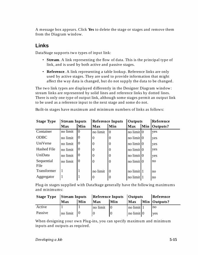
Developing a Job 5-15
A message box appears. Click Yes to delete the stage or stages and remove themfrom the Diagram window.
LinksDataStage supports two types of input link:
• Stream. A link representing the flow of data. This is the principal type oflink, and is used by both active and passive stages.
• Reference. A link representing a table lookup. Reference links are onlyused by active stages. They are used to provide information that mightaffect the way data is changed, but do not supply the data to be changed.
The two link types are displayed differently in the Designer Diagram window:stream links are represented by solid lines and reference links by dotted lines.There is only one type of output link, although some stages permit an output linkto be used as a reference input to the next stage and some do not.
Built-in stages have maximum and minimum numbers of links as follows:
Plug-in stages supplied with DataStage generally have the following maximumsand minimums:
When designing your own Plug-ins, you can specify maximum and minimuminputs and outputs as required.
Stage Type Stream Inputs Reference Inputs Outputs ReferenceMax Min Max Min Max Min Outputs?
Container no limit 0 no limit 0 no limit 0 yes
ODBC no limit 0 0 0 no limit 0 yesUniVerse no limit 0 0 0 no limit 0 yesHashed File no limit 0 0 0 no limit 0 yes
UniData no limit 0 0 0 no limit 0 yesSequentialFile
no limit 0 0 0 no limit 0 no
Transformer 1 1 no limit 0 no limit 1 noAggregator 1 1 0 0 no limit 1 no
Stage Type Stream Inputs Reference Inputs Outputs ReferenceMax Min Max Min Max Min Outputs?
Active 1 1 no limit 0 no limit 1 no
Passive no limit 0 0 0 no limit 0 yes
5-16 DataStage Developer’s Guide
Linking StagesYou can link stages in three ways:
• Using the Link icon. Choose the Link icon from the tool palette. Click thefirst stage and drag the link to the second stage. The link is made when yourelease the mouse button.
• Choosing Insert ➤ Link. Click the first stage and drag the link to thesecond stage. The link is made when you release the mouse button.
• Using the mouse. Select the first stage. Position the mouse cursor on theedge of a stage until the mouse cursor changes to a circle. Click and dragthe mouse to the other stage. The link is made when you release the mousebutton.
Each link is given a default name which you can change.
Moving LinksOnce positioned, a link (and its associated metadata) can be moved to a new loca-tion in the Diagram window. You can choose a new source or destination for thelink, but not both. To move a link:
1. Click the link to move in the Diagram window. The link is highlighted.
2. Click on the box at the end you wish to move and drag the end to its newlocation.
Deleting LinksLinks can be deleted from the Diagram window. Choose the link and do one of thefollowing:
• Press the Delete key.• Choose Edit ➤ Delete.• Choose Delete from the shortcut menu.
A message box appears. Click Yes to delete the link. The link is removed from theDiagram window.
Note: Metadata is associated with a link, not a stage. If you delete a link, the asso-ciated metadata is deleted too. If you want to retain the metadata you havedefined, do not delete the link; move it instead.
Developing a Job 5-17
Renaming LinksThere are two ways to rename a link; you can either replace its name entirely oredit the existing name.
To enter a new name:
1. Select the link in the Diagram window.
2. Type the new name. As soon as you start typing, an edit box appears over thecurrent name showing the characters being typed.
3. Press Enter or click outside the link to accept the edit. The link name ischanged in the Diagram window.
To modify a link name:
1. Select the link in the Diagram window.
2. Choose Edit ➤ Rename, choose Rename from the shortcut menu, or pressCtrl-R. An edit box appears over the existing name.
3. Make the required changes in the edit box.
4. Press Enter or click outside the link to accept the edit. The link name ischanged in the Diagram window.
Dealing with Multiple LinksIf you have multiple links from one stage to another, you may want to resize thestages in order to make the links clearer by spreading them out. Do this byselecting each stage and dragging on one of the sizing handles in the boundingbox.
Editing StagesWhen you have added the stages and links to the Diagram window, you must editthe stages to specify the data you want to use and any aggregations or conversionsrequired.
Data arrives into a stage on an input link and is output from a stage on an outputlink. The properties of the stage, the data on each input and output link, and anyaggregation or transforms required are specified using a stage editor.
To edit a stage, do one of the following:
• Double-click the stage in the Diagram window.• Select the stage and choose Properties… from the shortcut menu.• Choose Edit ➤ Rename.
5-18 DataStage Developer’s Guide
A dialog box appears. The content of this dialog box depends on the type of stageyou are editing. See the individual stage chapters for a detailed description of thestage dialog box.
The data on a link is specified using column definitions. The column definitions fora link are specified by editing a stage at either end of the link.
Column definitions are entered and edited identically for each stage type.
Specifying Column DefinitionsEach stage dialog box has a page for data inputs and/or data outputs (dependingon what links are present on the stage). The data flowing along each input oroutput link is specified using column definitions. The column definitions aredisplayed in a grid on the Columns page for each link.
The Columns grid has a row for each column definition and always has thefollowing entries:
• Column name. The name of the column.
• Key. Indicates whether the column is part of the primary key.
• SQL type. The SQL data type.
• Length. The data precision. This is the length for CHAR data and themaximum length for VARCHAR data.
• Scale. The data scale factor.
• Nullable. Specifies whether the column can contain null values.
• Display. The maximum number of characters required to display thecolumn data.
• Data element. The type of data in the column.
• Description. A text description of the column.
The grid may contain additional entries, depending on the type of stage you areediting. Specifically, stages that permit aggregating of output data (ODBC andUniVerse stages) also contain the following:
• Group. Choose Yes to specify that you want to group by this column.
• Derivation. Allows you to specify that you want to summarize using thiscolumn.
Developing a Job 5-19
Stages that support multivalued data (UniVerse, UniData, and Hashed File) alsocontain:
• Association. The name of the association (if any) that the column belongsto.
• Position. The field number.
• Type. The nesting type, which can be S, M, MV, or MS.
Some entries contain text (which you can edit) and others have a drop-down listcontaining all the available options for the cell.
You can edit the grid to add new column definitions or change values for existingdefinitions. For a detailed description of how to edit a grid, see Appendix B,“Editing Grids.” Any changes are saved when you save your job design.
The Columns page for each link also contains the following buttons which you canuse to edit the column definitions:
• Save… . Saves column definitions as a table definition in the Repository.
• Load… . Loads (copies) the column definitions from a table definition inthe Repository.
Editing Column DefinitionsYou can edit the column definitions for any input or output link. Do this by editingthe Columns grid.
To edit a column definition, click the cell you want to change. The way you edit thecell depends on the cell contents. If the cell contains a drop-down list, choose analternative option from the drop-down list. If the cell contains text, you can starttyping to change the value, or press F2 or choose Edit cell… from the shortcutmenu to put the cell into edit mode.
Some cells are complex, and require more than one piece of information. The Deri-vation column in the Aggregator stage output link is an example of this. In the caseof complex cells, editing will invoke a dialog box, allowing you to supply therequired information.
Inserting Column DefinitionsIf you want to create a new output column or write to a table that does not have atable definition, you can manually enter column definitions by editing the columnsgrid.
To add a new column at the bottom of the grid, edit the empty row (indicated by astar).
5-20 DataStage Developer’s Guide
To add a new column between existing rows, position the cursor in the row belowthe desired position and press the Insert key or choose Insert row… from theshortcut menu.
In either case, you can select and drag the new row to a new position in the grid.
For more information about adding and deleting rows, or moving between thecells of a grid, see Appendix B, “Editing Grids.”
Deleting Column DefinitionsIf you have a column definition you do not want, you can delete it. Unwantedcolumn definitions can arise if you load column definitions from a table definitionin the Repository (see “Loading Column Definitions” on page 5-21).
To delete a column definition, click anywhere in the row you want to remove andpress the Delete key or choose Delete row… from the shortcut menu. The columndefinition is removed from the grid. Click OK to close the Stage dialog box.Changes are saved when you save your job design.
If you want to delete more than one column definition at once, press Ctrl and clickin the row selector column for the rows you want to remove. Press the Delete keyor choose Delete row… from the shortcut menu to remove the selected columndefinitions.
Saving Column DefinitionsIf you edit column definitions or insert new definitions, you can save them in atable definition in the Repository. You can then load the definitions into otherstages in your job design.
To save the column definitions:
1. Click Save… . The Save Table Definition dialog box appears:
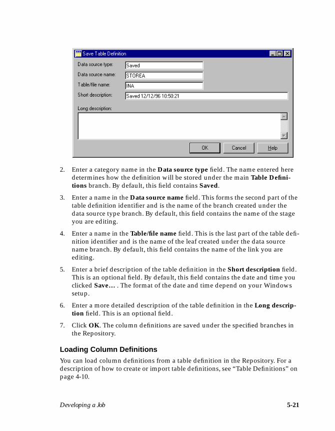
Developing a Job 5-21
2. Enter a category name in the Data source type field. The name entered heredetermines how the definition will be stored under the main Table Defini-tions branch. By default, this field contains Saved.
3. Enter a name in the Data source name field. This forms the second part of thetable definition identifier and is the name of the branch created under thedata source type branch. By default, this field contains the name of the stageyou are editing.
4. Enter a name in the Table/file name field. This is the last part of the table defi-nition identifier and is the name of the leaf created under the data sourcename branch. By default, this field contains the name of the link you areediting.
5. Enter a brief description of the table definition in the Short description field.This is an optional field. By default, this field contains the date and time youclicked Save… . The format of the date and time depend on your Windowssetup.
6. Enter a more detailed description of the table definition in the Long descrip-tion field. This is an optional field.
7. Click OK. The column definitions are saved under the specified branches inthe Repository.
Loading Column DefinitionsYou can load column definitions from a table definition in the Repository. For adescription of how to create or import table definitions, see “Table Definitions” onpage 4-10.
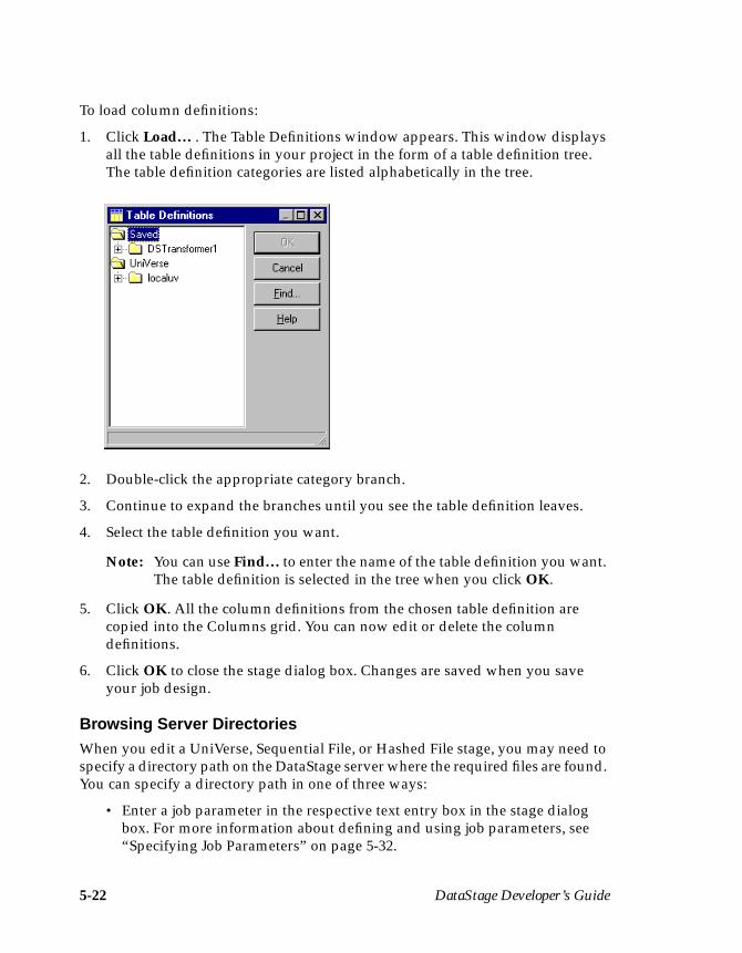
5-22 DataStage Developer’s Guide
To load column definitions:
1. Click Load… . The Table Definitions window appears. This window displaysall the table definitions in your project in the form of a table definition tree.The table definition categories are listed alphabetically in the tree.
2. Double-click the appropriate category branch.
3. Continue to expand the branches until you see the table definition leaves.
4. Select the table definition you want.
Note: You can use Find… to enter the name of the table definition you want.The table definition is selected in the tree when you click OK.
5. Click OK. All the column definitions from the chosen table definition arecopied into the Columns grid. You can now edit or delete the columndefinitions.
6. Click OK to close the stage dialog box. Changes are saved when you saveyour job design.
Browsing Server DirectoriesWhen you edit a UniVerse, Sequential File, or Hashed File stage, you may need tospecify a directory path on the DataStage server where the required files are found.You can specify a directory path in one of three ways:
• Enter a job parameter in the respective text entry box in the stage dialogbox. For more information about defining and using job parameters, see“Specifying Job Parameters” on page 5-32.

Developing a Job 5-23
• Enter the directory path directly in the respective text entry box in the Stagedialog box.
• Use Browse… .
If you use Browse…, the Browse directories dialog box appears. This dialog boxhas the following features:
• Directory on field. Displays the directory path. This field is automaticallyupdated with the drive and directory you choose. You can also enter adirectory path directly in this field.
• Directory list. Displays the directories on the chosen drive. Double-clickthe directory you want. Double-click .. to move up a level in the directorystructure.
• Drive on list (only shown when connected to a Windows NT server).Displays the mounted drives on the DataStage server. Choose the driveyou want from the drop-down list. The Directory list box is automaticallyupdated when you choose a drive.
• OK button. Accepts the directory path in the Directory on field and closesthe Browse directories dialog box.
• Cancel button. Closes the dialog box without specifying a directory path.
• Help button. Invokes the Help system.
Using the Data BrowserYou can browse the data associated with the input or output links of any built-inpassive stage. The Data Browser is invoked by clicking the View Data… buttonfrom a Stage Inputs or Outputs page, or by choosing the View link Data… optionfrom the shortcut menu. The Data Browser window appears:
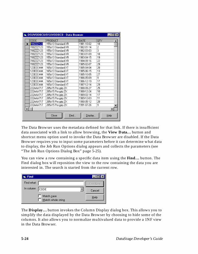
5-24 DataStage Developer’s Guide
The Data Browser uses the metadata defined for that link. If there is insufficientdata associated with a link to allow browsing, the View Data… button andshortcut menu option used to invoke the Data Browser are disabled. If the DataBrowser requires you to input some parameters before it can determine what datato display, the Job Run Options dialog appears and collects the parameters (see“The Job Run Options Dialog Box” page 5-25).
You can view a row containing a specific data item using the Find… button. TheFind dialog box will reposition the view to the row containing the data you areinterested in. The search is started from the current row.
The Display… button invokes the Column Display dialog box. This allows you tosimplify the data displayed by the Data Browser by choosing to hide some of thecolumns. It also allows you to normalize multivalued data to provide a 1NF viewin the Data Browser.
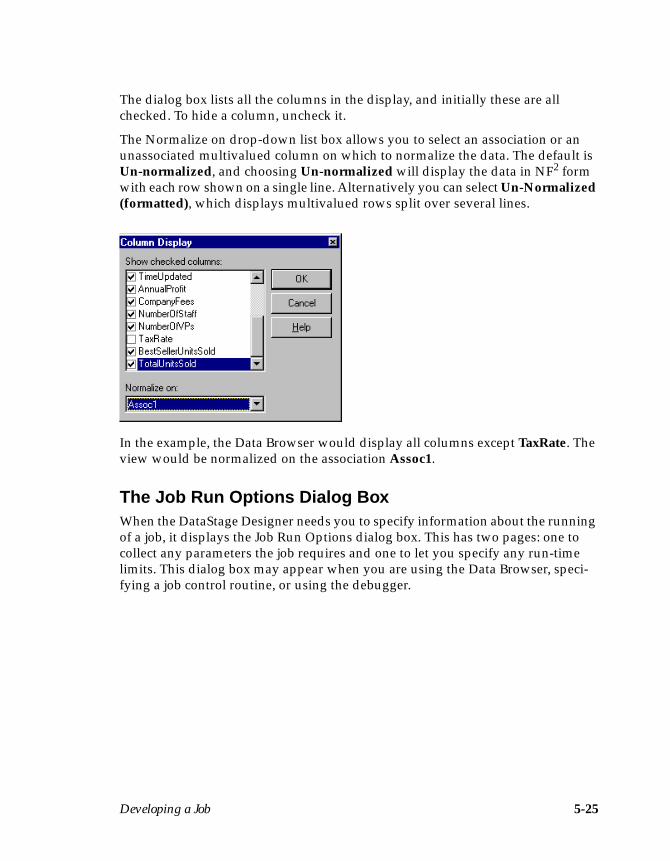
Developing a Job 5-25
The dialog box lists all the columns in the display, and initially these are allchecked. To hide a column, uncheck it.
The Normalize on drop-down list box allows you to select an association or anunassociated multivalued column on which to normalize the data. The default isUn-normalized, and choosing Un-normalized will display the data in NF2 formwith each row shown on a single line. Alternatively you can select Un-Normalized(formatted), which displays multivalued rows split over several lines.
In the example, the Data Browser would display all columns except TaxRate. Theview would be normalized on the association Assoc1.
The Job Run Options Dialog BoxWhen the DataStage Designer needs you to specify information about the runningof a job, it displays the Job Run Options dialog box. This has two pages: one tocollect any parameters the job requires and one to let you specify any run-timelimits. This dialog box may appear when you are using the Data Browser, speci-fying a job control routine, or using the debugger.
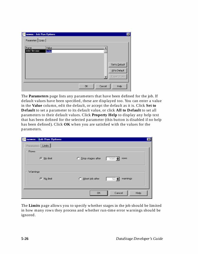
5-26 DataStage Developer’s Guide
The Parameters page lists any parameters that have been defined for the job. Ifdefault values have been specified, these are displayed too. You can enter a valuein the Value column, edit the default, or accept the default as it is. Click Set toDefault to set a parameter to its default value, or click All to Default to set allparameters to their default values. Click Property Help to display any help textthat has been defined for the selected parameter (this button is disabled if no helphas been defined). Click OK when you are satisfied with the values for theparameters.
The Limits page allows you to specify whether stages in the job should be limitedin how many rows they process and whether run-time error warnings should beignored.
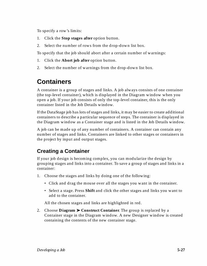
Developing a Job 5-27
To specify a row’s limits:
1. Click the Stop stages after option button.
2. Select the number of rows from the drop-down list box.
To specify that the job should abort after a certain number of warnings:
1. Click the Abort job after option button.
2. Select the number of warnings from the drop-down list box.
ContainersA container is a group of stages and links. A job always consists of one container(the top-level container), which is displayed in the Diagram window when youopen a job. If your job consists of only the top-level container, this is the onlycontainer listed in the Job Details window.
If the DataStage job has lots of stages and links, it may be easier to create additionalcontainers to describe a particular sequence of steps. The container is displayed inthe Diagram window as a Container stage and is listed in the Job Details window.
A job can be made up of any number of containers. A container can contain anynumber of stages and links. Containers are linked to other stages or containers inthe project by input and output stages.
Creating a ContainerIf your job design is becoming complex, you can modularize the design bygrouping stages and links into a container. To save a group of stages and links in acontainer:
1. Choose the stages and links by doing one of the following:
• Click and drag the mouse over all the stages you want in the container.
• Select a stage. Press Shift and click the other stages and links you want toadd to the container.
All the chosen stages and links are highlighted in red.
2. Choose Diagram ➤ Construct Container. The group is replaced by aContainer stage in the Diagram window. A new Designer window is createdcontaining the contents of the new container stage.
5-28 DataStage Developer’s Guide
Adding a Container StageIf you want to describe a series of processing steps in a contained group, you canadd a Container stage to your job design. The Container stage is edited to includethe stages and links required.
To add a Container stage, do one of the following:
• Choose Insert ➤ Container.• Click the Container icon on the tool palette.
A Container stage is added to the Diagram window and the container name isadded to the Job Details window.
Viewing or Modifying a ContainerTo view or modify the stages or links in a container, do one of the following:
• Double-click the container stage in the Diagram window.• Double-click the container name in the Job Details window.• Select the container and choose Edit ➤ Properties… .• Select the container and choose Properties… from the shortcut menu.
Another Diagram window appears with the contents of the container. You can tilethe Diagram windows so that the container is displayed beneath the mainDiagram window.
You can edit the stages and links in a container in the same way you do for the top-level container.
Click the Close button to close the Diagram window for the container.
Using Input and Output StagesWhen you use containers in a job design, a link is displayed going in to or out ofthe container. However, it is not apparent which stage in the container forms theother end of the link.
The link between a stage and a container is represented in the container Diagramwindow by a Container Input or Output stage.
The way in which the Container Input and Output stages are used depends onwhether you create or add a container:
• If you create a container, the input and output stages are automaticallyadded. The link between the input or output stage and the stage in thecontainer has the same name as the link in the main Diagram window.
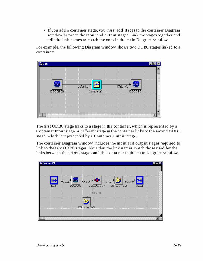
Developing a Job 5-29
• If you add a container stage, you must add stages to the container Diagramwindow between the input and output stages. Link the stages together andedit the link names to match the ones in the main Diagram window.
For example, the following Diagram window shows two ODBC stages linked to acontainer:
The first ODBC stage links to a stage in the container, which is represented by aContainer Input stage. A different stage in the container links to the second ODBCstage, which is represented by a Container Output stage.
The container Diagram window includes the input and output stages required tolink to the two ODBC stages. Note that the link names match those used for thelinks between the ODBC stages and the container in the main Diagram window.
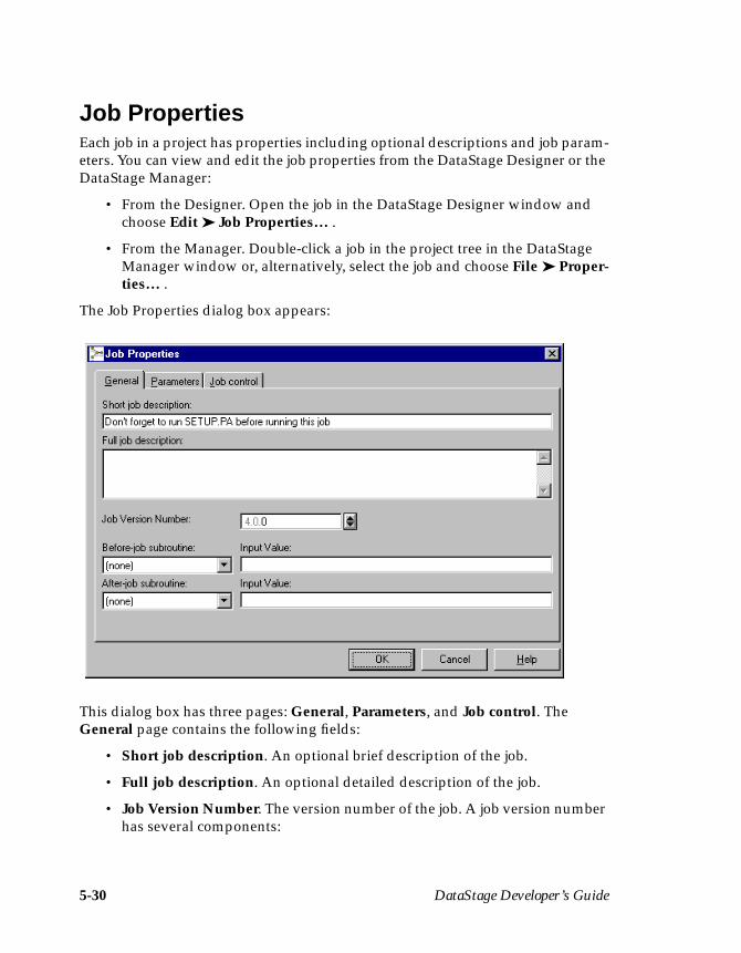
5-30 DataStage Developer’s Guide
Job PropertiesEach job in a project has properties including optional descriptions and job param-eters. You can view and edit the job properties from the DataStage Designer or theDataStage Manager:
• From the Designer. Open the job in the DataStage Designer window andchoose Edit ➤ Job Properties… .
• From the Manager. Double-click a job in the project tree in the DataStageManager window or, alternatively, select the job and choose File ➤ Proper-ties… .
The Job Properties dialog box appears:
This dialog box has three pages: General, Parameters, and Job control. TheGeneral page contains the following fields:
• Short job description. An optional brief description of the job.
• Full job description. An optional detailed description of the job.
• Job Version Number. The version number of the job. A job version numberhas several components:
Developing a Job 5-31
– The version number: N.n.n. This number checks the compatibility of thejob with the version of DataStage installed. This number is automaticallyset when DataStage is installed and cannot be edited.
– The release number: n.N.n. This number is automatically incrementedevery time you release a job. For more information about releasing jobs,see “Releasing a Job” on page 17-7.
– The bug fix number: n.n.N. This number reflects minor changes to the jobdesign or properties. To change this number, select it and enter a newvalue directly or use the arrow buttons to increase the number.
• Before-job subroutine and Input Value. Optionally contain the name (andinput parameter value) of a subroutine that is executed before the job runs.For example, you can specify a routine that prepares the data beforeprocessing starts.
Choose a routine from the drop-down list box. This list box contains all thebuilt routines defined as a Before/After Subroutine under the Routinesbranch in the Repository. Enter an appropriate value for the routine’s inputargument in the Input Value field.
If you use a routine that is defined in the Repository, but which was editedand not compiled, a warning message reminds you to compile the routinewhen you close the Job Properties dialog box.
If you installed or imported a job, the Before-job subroutine field mayreference a routine which does not exist on your system. In this case, awarning message appears when you close the Job Properties dialog box.You must install or import the “missing” routine or choose an alternativeone to use.
• After-job subroutine and Input Value. Optionally contain the name (andinput parameter value) of a subroutine that is executed after the job hasfinished. For example, you can specify a routine that sends an electronicmessage when the job finishes.
Choose a routine from the drop-down list box. This list box contains all thebuilt routines defined as a Before/After Subroutine under the Routinesbranch in the Repository. Enter an appropriate value for the routine’s inputargument in the Input Value field.
If you use a routine that is defined in the Repository, but which was editedbut not compiled, a warning message reminds you to compile the routinewhen you close the Job Properties dialog box.
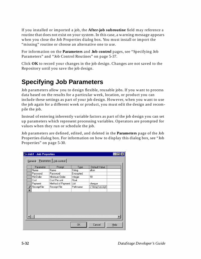
5-32 DataStage Developer’s Guide
If you installed or imported a job, the After-job subroutine field may reference aroutine that does not exist on your system. In this case, a warning message appearswhen you close the Job Properties dialog box. You must install or import the“missing” routine or choose an alternative one to use.
For information on the Parameters and Job control pages, see “Specifying JobParameters” and “Job Control Routines” on page 5-37.
Click OK to record your changes in the job design. Changes are not saved to theRepository until you save the job design.
Specifying Job ParametersJob parameters allow you to design flexible, reusable jobs. If you want to processdata based on the results for a particular week, location, or product you caninclude these settings as part of your job design. However, when you want to usethe job again for a different week or product, you must edit the design and recom-pile the job.
Instead of entering inherently variable factors as part of the job design you can setup parameters which represent processing variables. Operators are prompted forvalues when they run or schedule the job.
Job parameters are defined, edited, and deleted in the Parameters page of the JobProperties dialog box. For information on how to display this dialog box, see “JobProperties” on page 5-30.

Developing a Job 5-33
The Job Parameters grid has the following columns:
• Parameter. The name of the parameter.• Prompt. Text used as the field name in the run-time dialog box.• Type. The type of the parameter (to enable validation)• Default Value. The default setting for the parameter.• Help Text. The text that appears if a user clicks Property Help in the Job
Run Options dialog box when running the job.
Parameter TypesSpecify the type of the parameter by choosing one of the following from the drop-down list:
• String. The default type.
• Encrypted. Used to specify a password. The default value is set by double-clicking the Default Value cell to invoke the Setup Password dialog box.Type the password in the Encrypted String field and retype it in theConfirm Encrypted String field. It is displayed as asterisks.
• Integer. Long int (–2147483648 to +2147483647).
• Float. Double (1.79769313486232E308 to –4.94065645841247E–324 and4.94065645841247E–324 to –1.79769313486232E308).
• Pathname. Enter a default pathname or filename by typing it into DefaultValue or double-click the Default Value cell to invoke the Browse dialogbox.
• List. A list of valid string variables. To set up a list, double-click the DefaultValue cell to invoke the Set Defaults dialog box. Build up a list by typing ineach item into the Value field then clicking Add. The item then appears inthe List box. To remove an item, select it in the List box and click Remove.Select one of the items from the Set Default drop-down list box to be thedefault.

5-34 DataStage Developer’s Guide
• Date. Date in the ISO format yyy-mm-dd.
• Time. Time in the format hh:mm:ss.
DataStage uses the parameter type to validate any values that are subsequentlysupplied for that parameter, be it in the Director or the Designer.
Parameter DefaultsYou can supply default values for parameters, which are used unless another valueis specified when the job is run. For most parameter types, you simply type anappropriate default value into the Default Value cell. When specifying a passwordor a list variable, double-click the Default Value cell to invoke further dialog boxeswhich allow you to supply defaults.
Defining Job ParametersJob parameters are defined by editing the empty row (indicated by a star) in theJob Parameters grid. For more information about adding and deleting rows, ormoving between the cells of a grid, see Appendix B, “Editing Grids.”
When you have added all the job parameters you need, click OK to close the JobProperties dialog box.
Editing Job ParametersYou can edit any existing job parameter definition. To edit a job parameter, click thecell you want to change. The way you edit the cell depends on the cell contents. Ifthe cell contains a drop-down list, choose an alternative option from the drop-down list.
Developing a Job 5-35
If the cell contains text, you can start typing to change the value or press F2 to putthe cell into edit mode. When you finish making any changes, click OK to close theJob Properties dialog box.
Deleting Job ParametersYou can delete any of the job parameters defined in the Job Properties dialog box.
CAUTION: Before you remove a job parameter definition you must make surethat you remove the references to this parameter in your job design.If you do not do this, your job may fail to run.
To delete a job parameter definition:
1. Click anywhere in the row for the job parameter you want to remove andpress the Delete key or choose Delete row from the shortcut menu. Amessage box appears.
2. Click Yes to delete the job parameter.
3. Click OK to close the Job Properties dialog box.
To delete more than one job parameter at once, press Ctrl and click in the rowselector column for the rows you want to remove, then press the Delete key orchoose Delete row… from the shortcut menu. A message box appears. Click Yesto delete the parameters.
Using Job ParametersTo use the defined job parameters, you must specify them when you edit a stage.When you edit a field that you wish to use a parameter for, enter #Param#, whereParam is the name of the job parameter. The string #Param# is replaced by the valuefor the job parameter when the job is run. (For more details about editing stages,see “Editing Stages” on page 5-17.)
A job parameter can be used in any stage or link property, for example:
• In Transformer stages. You can use job parameters in the following fieldswhen you edit a Transformer stage:
– Key Expression cell of a reference input link
– Constraint on an output link.
– Derivation cell of an output link.
5-36 DataStage Developer’s Guide
You can use the Expression Editor to insert a job parameter in these fields.For information about the Expression Editor, see “The DataStage Expres-sion Editor” on page 11-12.
• In Sequential File stages. You can use job parameters in the following fieldsin the Sequential File Stage dialog box:
– Directory where files are held field on the Stage page– File name field on the Inputs or Outputs page
• In ODBC or UniVerse stages. You can use job parameters in the followingfields in the Stage dialog box:
– Data source name field on the General page on the Stage page
– User name and Password fields on the General page on the Stage page
– Account name or Use directory path fields on the Details page on theStage page (UniVerse Stage only)
– Table name field on the General page on the Inputs or Outputs page
– WHERE clause field on the Selection page on the Outputs page
– Value cell on the Parameters page, which appears in the Outputs pagewhen you use a stored procedure (ODBC Stage only)
– Expression field on the Derivation dialog box, invoked from the Deriva-tion column in the Outputs page of a UniVerse or ODBC Stage dialog box
• In Hashed File stages. You can use job parameters in the following fields inthe Hashed File Stage dialog box:
– Use account name or Use directory path fields on the Stage page– File name field on the General page on the Inputs or Outputs page
• In UniData stages. You can use job parameters in the following fields in theUniData Stage dialog box:
– Server, Database, User name, and Password fields on the Stage page– File name field on the General page on the Inputs or Outputs page
• Before and After Subroutines. You can use job parameters to specify argu-ment values for before and after subroutines.
Note: You can also use job parameters in the Property name field on the Proper-ties page in the Stage Type dialog box when you create a Plug-in. For moreinformation, see “Registering a Plug-in Definition” on page 13-2.

Developing a Job 5-37
Job Control RoutinesA job control routine provides the means of controlling other jobs from within thecurrent job. A set of one or more jobs can be validated, run, reset, stopped, andscheduled in much the same way as the current job can be. You can, if required, setup a job whose only function is to control a set of other jobs.
To control other jobs in this way, you must define a job control routine in the Jobcontrol page of the Job Properties dialog box. The routine uses a set of BASIC func-tions provided for the purpose. For more information about these routines, seeDataStage Developer’s Help. The Job control page provides a basic editor to letyou construct a job control routine using the functions.
The toolbar contains buttons for cutting, copying, pasting, and formatting code,and for activating Find (and Replace). The main part of this page consists of amultiline text box with scroll bars. The Add job field provides a drop-down list boxof all the jobs in the current project. When you select a compiled job from the listand click Add, the Job Run Options dialog box appears, allowing you to specifyany parameters or run-time limits to apply when the selected job is run (see “TheJob Run Options Dialog Box” page 5-25). When you click OK in the Job RunOptions dialog box, you return to the Job control page, where you will find thatDataStage has added job control code for the selected job. The code sets anyrequired job parameters and/or limits, runs the job, waits for it to finish, then testsfor success.
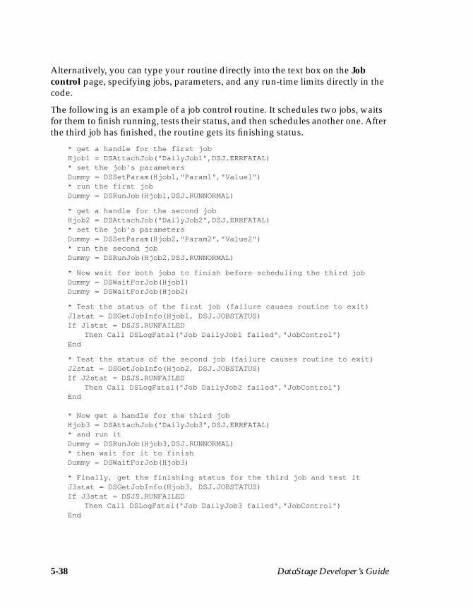
5-38 DataStage Developer’s Guide
Alternatively, you can type your routine directly into the text box on the Jobcontrol page, specifying jobs, parameters, and any run-time limits directly in thecode.
The following is an example of a job control routine. It schedules two jobs, waitsfor them to finish running, tests their status, and then schedules another one. Afterthe third job has finished, the routine gets its finishing status.
* get a handle for the first jobHjob1 = DSAttachJob("DailyJob1",DSJ.ERRFATAL)* set the job's parametersDummy = DSSetParam(Hjob1,"Param1","Value1")* run the first jobDummy = DSRunJob(Hjob1,DSJ.RUNNORMAL)
* get a handle for the second jobHjob2 = DSAttachJob("DailyJob2",DSJ.ERRFATAL)* set the job's parametersDummy = DSSetParam(Hjob2,"Param2","Value2")* run the second jobDummy = DSRunJob(Hjob2,DSJ.RUNNORMAL)
* Now wait for both jobs to finish before scheduling the third jobDummy = DSWaitForJob(Hjob1)Dummy = DSWaitForJob(Hjob2)
* Test the status of the first job (failure causes routine to exit)J1stat = DSGetJobInfo(Hjob1, DSJ.JOBSTATUS)If J1stat = DSJS.RUNFAILED
Then Call DSLogFatal("Job DailyJob1 failed","JobControl")End
* Test the status of the second job (failure causes routine to exit)J2stat = DSGetJobInfo(Hjob2, DSJ.JOBSTATUS)If J2stat = DSJS.RUNFAILED
Then Call DSLogFatal("Job DailyJob2 failed","JobControl")End
* Now get a handle for the third jobHjob3 = DSAttachJob("DailyJob3",DSJ.ERRFATAL)* and run itDummy = DSRunJob(Hjob3,DSJ.RUNNORMAL)* then wait for it to finishDummy = DSWaitForJob(Hjob3)
* Finally, get the finishing status for the third job and test itJ3stat = DSGetJobInfo(Hjob3, DSJ.JOBSTATUS)If J3stat = DSJS.RUNFAILED
Then Call DSLogFatal("Job DailyJob3 failed","JobControl")End
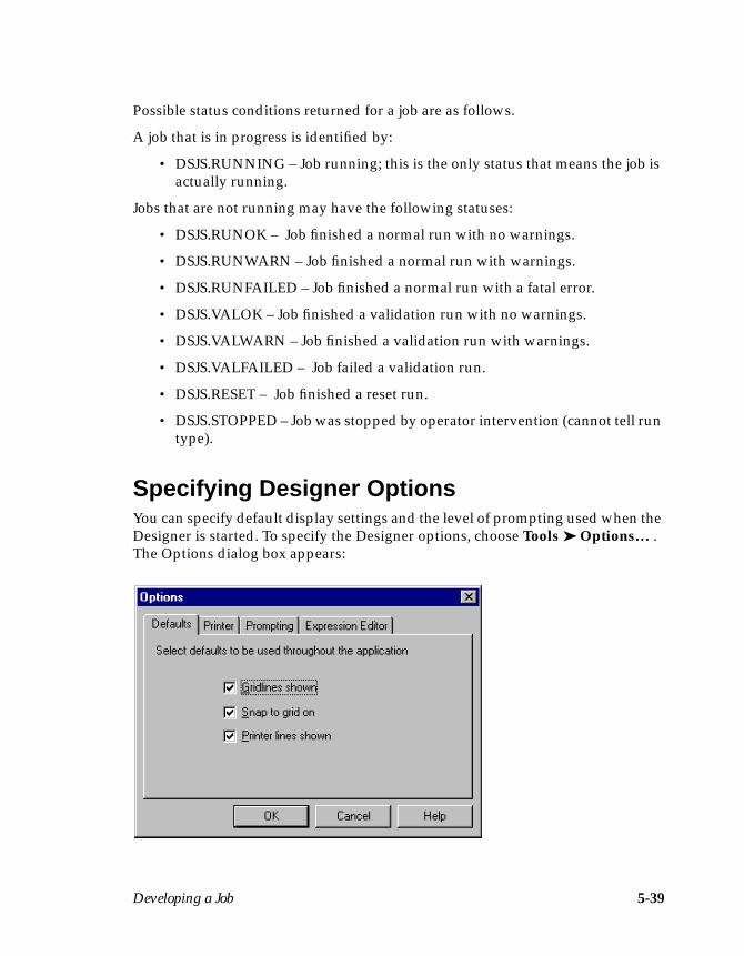
Developing a Job 5-39
Possible status conditions returned for a job are as follows.
A job that is in progress is identified by:
• DSJS.RUNNING – Job running; this is the only status that means the job isactually running.
Jobs that are not running may have the following statuses:
• DSJS.RUNOK – Job finished a normal run with no warnings.
• DSJS.RUNWARN – Job finished a normal run with warnings.
• DSJS.RUNFAILED – Job finished a normal run with a fatal error.
• DSJS.VALOK – Job finished a validation run with no warnings.
• DSJS.VALWARN – Job finished a validation run with warnings.
• DSJS.VALFAILED – Job failed a validation run.
• DSJS.RESET – Job finished a reset run.
• DSJS.STOPPED – Job was stopped by operator intervention (cannot tell runtype).
Specifying Designer OptionsYou can specify default display settings and the level of prompting used when theDesigner is started. To specify the Designer options, choose Tools ➤ Options… .The Options dialog box appears:

5-40 DataStage Developer’s Guide
This dialog box has four pages:
• Defaults. Determines the actions set in the Diagram window when youstart the Designer. There are three check boxes on this page:
– Gridlines shown– Snap to grid on– Printer lines shown
These check boxes are selected by default. Clear the check box you do notwant to set on startup.
• Printer. Specifies the printing orientation. When you choose File ➤ Print,the default printing orientation is determined by the setting on this page.You can choose portrait or landscape orientation. To use portrait, select thePortrait orientation check box. The default setting for this option isunchecked, i.e., landscape orientation is used.
• Prompting. Determines the level of prompting displayed when you deletea stage or link in a job design. This page has options for deleting a link andoptions for deleting a stage or a container.
The following options describe the action that occurs when you delete alink:
– Always prompt. You are always prompted to confirm the deletion.
– Never prompt. The chosen link or links are deleted without any confir-mation. If you choose this option, containers (and the stages and links inthem) are deleted without prompting.
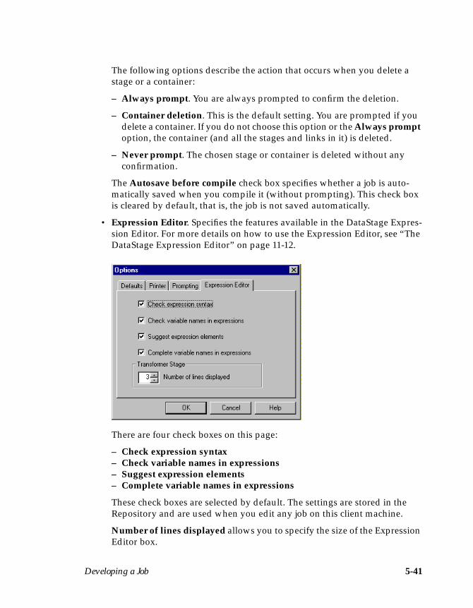
Developing a Job 5-41
The following options describe the action that occurs when you delete astage or a container:
– Always prompt. You are always prompted to confirm the deletion.
– Container deletion. This is the default setting. You are prompted if youdelete a container. If you do not choose this option or the Always promptoption, the container (and all the stages and links in it) is deleted.
– Never prompt. The chosen stage or container is deleted without anyconfirmation.
The Autosave before compile check box specifies whether a job is auto-matically saved when you compile it (without prompting). This check boxis cleared by default, that is, the job is not saved automatically.
• Expression Editor. Specifies the features available in the DataStage Expres-sion Editor. For more details on how to use the Expression Editor, see “TheDataStage Expression Editor” on page 11-12.
There are four check boxes on this page:
– Check expression syntax– Check variable names in expressions– Suggest expression elements– Complete variable names in expressions
These check boxes are selected by default. The settings are stored in theRepository and are used when you edit any job on this client machine.
Number of lines displayed allows you to specify the size of the ExpressionEditor box.

5-42 DataStage Developer’s Guide
Click OK to save any changes and to close the Options dialog box. The chosensettings take effect immediately.

ODBC Stages 6-1
6ODBC Stages
ODBC stages are used to represent a database that supports the industry standardOpen Database Connectivity API. You can use an ODBC stage to extract, write, oraggregate data.
Each ODBC stage can have any number of inputs or outputs. Input links specifythe data you are writing. Output links specify the data you are extracting and anyaggregations required.
You can specify the data on an input or output link using an SQL statementconstructed by DataStage, a user-defined query, or a stored procedure.
When you edit an ODBC stage, the ODBC Stage dialog box appears:
6-2 DataStage Developer’s Guide
This dialog box can have up to three pages (depending on whether there are inputsto and outputs from the stage):
• Stage. Displays the name of the stage you are editing. You can enter text todescribe the purpose of the stage in the Description field. The Generalpage defines the data source name and connection type. You can connect toan ODBC data source. For details see “Defining the Connection.”
Note: You cannot change the name of the stage from this dialog box. Fordetails on how to change stage names, see “Renaming Stages” onpage 5-14.
• Inputs. This page is displayed only if you have an input link to this stage.Specifies the SQL table or stored procedure to use and the associatedcolumn definitions for each data input link. This page also specifies howdata is written and contains the SQL statement or call syntax used to writethe data.
• Outputs. This page is displayed only if you have an output link to thisstage. Specifies the SQL tables or stored procedure to use and the associ-ated column definitions for each data output link. This page also containsthe SQL SELECT statement or call syntax used to extract the data.
You must perform the following steps to edit an ODBC stage:
1. Define the connection.
2. Define the data on the input links.
3. Define the data on the output links.
These steps are performed in the ODBC Stage dialog box. Click OK to close thisdialog box. Changes are saved when you save the job design.
Defining the ConnectionTo connect to an ODBC data source, you must install and configure a suitableODBC driver on your system. For more information, see DataStage Administrator’sGuide.
ODBC Stages 6-3
ODBC Connection ParametersThe ODBC connection parameters are set on the General page on the Stage page.To connect to an ODBC data source:
1. Choose the data source name from the Data source name drop-down list box.This drop-down list box contains all the data sources defined under the TableDefinitions ➤ ODBC branch in the Repository.
Note: If the data source name you want is not listed, enter the name in theData source name field or define a table definition. For details on howto import or create a table definition, see Chapter 4, “Setting Up aProject.”
You can also enter a job parameter in this field. For details on how to defineand use job parameters, see “Specifying Job Parameters” on page 5-32.
2. Enter the name to use to connect to the data source in the User name field.(You can also enter a job parameter in this field.)
3. Enter the password to use in the Password field. (You can also enter a jobparameter in this field.)
Note: Certain ODBC drivers allow you to specify the user name and pass-word to use on connection. If you are connecting to an ODBC datausing a driver that has a user name and password already specified,you do not need to enter a user name and password on the Generalpage.
4. Choose an appropriate transaction isolation level to use from the Transactionisolation level drop-down list box.
5. Enter a suitable value in the Rows per transaction field. This is the number ofrows written before the data is committed to the data table. The default valueis 0, that is, all the rows are written before being committed to the data table.
6. Enter a suitable value in the Parameter array size field. This is the number ofrows written at a time. The default is 1, that is, each row is written in a sepa-rate operation.
7. Enter an optional description of the ODBC stage in the Description field.
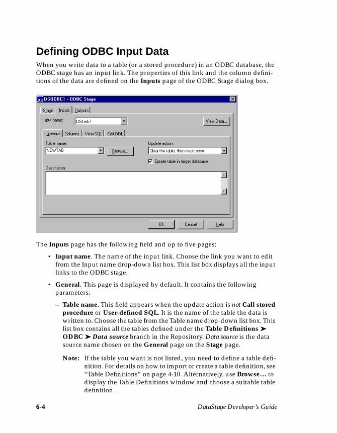
6-4 DataStage Developer’s Guide
Defining ODBC Input DataWhen you write data to a table (or a stored procedure) in an ODBC database, theODBC stage has an input link. The properties of this link and the column defini-tions of the data are defined on the Inputs page of the ODBC Stage dialog box.
The Inputs page has the following field and up to five pages:
• Input name. The name of the input link. Choose the link you want to editfrom the Input name drop-down list box. This list box displays all the inputlinks to the ODBC stage.
• General. This page is displayed by default. It contains the followingparameters:
– Table name. This field appears when the update action is not Call storedprocedure or User-defined SQL. It is the name of the table the data iswritten to. Choose the table from the Table name drop-down list box. Thislist box contains all the tables defined under the Table Definitions ➤ODBC ➤ Data source branch in the Repository. Data source is the datasource name chosen on the General page on the Stage page.
Note: If the table you want is not listed, you need to define a table defi-nition. For details on how to import or create a table definition, see“Table Definitions” on page 4-10. Alternatively, use Browse… todisplay the Table Definitions window and choose a suitable tabledefinition.

ODBC Stages 6-5
You can also enter a job parameter in this field. For details on how todefine and use job parameters, see “Specifying Job Parameters” onpage 5-32.
– Procedure name. This field appears only when the update action is Callstored procedure. It is the name of the procedure the data is written to.Choose the stored procedure you want to use from the drop-down listbox. This list box contains all the stored procedures defined under theTable Definitions ➤ StoredProcedures branch in the Repository for thespecified DSN.
Note: If the stored procedure you want is not listed, you need to defineit. For details on how to import or create a stored procedure defi-nition, see “Stored Procedure Definitions” on page 4-30.Alternatively, use Browse… to search for the stored procedureyou want.
– Update action. Specifies how the data is written. Choose the option youwant from the drop-down list box:
Clear the table, then insert rows. Deletes the contents of the table andadds the new rows.
Insert rows without clearing. Inserts the new rows in the table.
Replace existing rows completely. Deletes the existing rows, then addsthe new rows to the table.
Update existing rows only. Updates the existing data rows. Any rows inthe data that do not exist in the table are ignored.
Insert new or update existing rows. New rows are added or, if the insertfails, the existing rows are updated.
Update existing or insert new rows. The existing data rows are updatedor, if this fails, new rows are added.
Call stored procedure. Writes the data using a stored procedure. Whenyou select this option, the Procedure name field appears.
User-defined SQL. Writes the data using a user-defined SQL statement.When you select this option, the View SQL page is replaced by the EnterSQL page.
– Create table in target database. Select this check box if you want to auto-matically create a table in the target database at run time. A table iscreated based on the defined column set for this stage. If you select thisoption, an additional page, Edit DDL, appears. This shows the SQLCREATE statement to be used for table generation.

6-6 DataStage Developer’s Guide
– Description. Contains an optional description of the input link.
• Columns. Contains the column definitions for the data written to the tableor file. If you are using a stored procedure, the column definitions representthe stored procedure input parameters. You must have at least the samenumber of column definitions as expected parameters. The column defini-tions are used in the order they appear in the Columns grid. For adescription of how to enter and edit column definitions, see “SpecifyingColumn Definitions” on page 5-18.
• View SQL. Displays the SQL statement or stored procedure call syntaxused to write the data. You cannot edit this statement, but you can useCopy to copy it to the Clipboard for use elsewhere.
• Enter SQL. Displays the user-defined SQL statement. This page appearsonly when you set the update action to User-defined SQL.
• Edit DDL. This page appears if you have chosen to automatically generatea table at run time by selecting the Create table in target database checkbox on the General page. It displays the SQL CREATE statement that willbe used to create the table. To generate the statement, click the Create DDLbutton. DataStage will connect to the target database and generate thestatement. (Note that, if you are creating a table in a Sybase database, theSybase database needs to have the “Data definition language in transac-tion” option set.) You can edit the statement on this page to make anyrequired changes. This page also allows you to specify that any existingtable by this name should be dropped first. If you do not select this option,and such a table already exists in the target database, then the create willfail.
Click the View Data… button to invoke the Data Browser. This enables you to lookat the data associated with the input link. For a description of the Data Browser, see“Using the Data Browser” on page 5-23.
Using a Generated QueryYou can write data to an SQL table using an SQL statement constructed byDataStage. When you specify the table and the column definitions to use, the SQLstatement is automatically constructed and can be viewed on the View SQL page.
To use a generated query:
1. Choose a table from the Table name drop-down list box on the General page.
ODBC Stages 6-7
2. Specify how you want the data to be written by choosing a suitable optionfrom the Update action drop-down list box. There are six options for a gener-ated query:
• Clear the table, then insert rows• Insert rows without clearing• Replace existing rows completely• Update existing rows only• Insert new or update existing rows• Update existing or insert new rows
See page 6-5 for a description of each update action.
3. Enter an optional description of the input link in the Description field.
4. Click the Columns tab. The Columns page appears at the front of the Inputspage.
5. Edit the Columns grid to specify column definitions for the columns youwant to write. For more information, see “Specifying Column Definitions” onpage 5-18.
The SQL statement is automatically constructed using your chosen updateaction and the columns you have specified. You can now optionally view thisSQL statement.
6. Click the View SQL tab. The View SQL page appears at the front of theInputs page.
7. Click OK to close the ODBC Stage dialog box. Changes are saved when yousave your job design.
Using a User-defined SQL StatementInstead of writing data using an SQL statement constructed by DataStage, you canenter your own SQL statement for each ODBC input link.
To enter an SQL statement:
1. Choose User-defined SQL from the Update action drop-down list box. TheView SQL page is replaced with the Enter SQL page.
2. Click the Columns tab. The Columns page appears at the front of the Inputspage.
3. Edit the Columns grid to specify column definitions for the columns youwant to write. For more information, see “Specifying Column Definitions” onpage 5-18.
6-8 DataStage Developer’s Guide
4. Click the Enter SQL tab. The Enter SQL page appears at the front of theInputs page.
5. Enter the SQL statement you want to use. This statement must contain thetable name, the type of update action you want to perform, and the columnsyou want to write.
Note: You must also ensure that the statement contains the correct number of? parameter markers. You must have a parameter marker for eachcolumn you have defined on the Columns page.
6. Click OK to close the ODBC Stage dialog box. Changes are saved when yousave your job design.
Using a Stored ProcedureInstead of writing data to a table using an SQL statement, you can write data to astored procedure. The columns you define are bound (in order) to the input param-eters in the stored procedure. The call syntax used to write the data is constructedby DataStage and can be viewed on the View SQL page.
The procedure is called once for each row of data presented to the input link.
To use a stored procedure:
1. Choose Call stored procedure from the Update action drop-down list box onthe General page. The Table name drop-down list box is replaced by theProcedure name drop-down list box.
2. Choose the stored procedure from the Procedure name drop-down list box.
3. Enter an optional description of the input link in the Description field.
4. Click the Columns tab. The Columns page appears at the front of the Inputspage.
5. Edit the Columns grid to specify column definitions. For more information,see “Specifying Column Definitions” on page 5-18. The column definitionsare used as the input parameters to the stored procedure. You must have atleast the same number of column definitions as the number of expected inputparameters.
The call statement is automatically constructed using the stored procedurename and the columns you have specified. You can now optionally view thisSQL statement.
6. Click the View SQL tab. The View SQL page appears at the front of theInputs page.
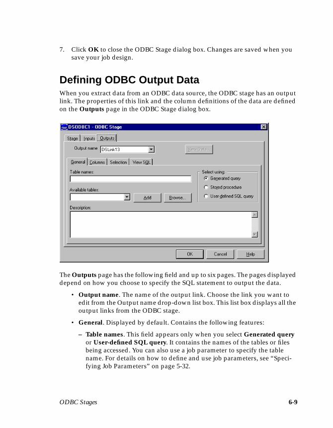
ODBC Stages 6-9
7. Click OK to close the ODBC Stage dialog box. Changes are saved when yousave your job design.
Defining ODBC Output DataWhen you extract data from an ODBC data source, the ODBC stage has an outputlink. The properties of this link and the column definitions of the data are definedon the Outputs page in the ODBC Stage dialog box.
The Outputs page has the following field and up to six pages. The pages displayeddepend on how you choose to specify the SQL statement to output the data.
• Output name. The name of the output link. Choose the link you want toedit from the Output name drop-down list box. This list box displays all theoutput links from the ODBC stage.
• General. Displayed by default. Contains the following features:
– Table names. This field appears only when you select Generated queryor User-defined SQL query. It contains the names of the tables or filesbeing accessed. You can also use a job parameter to specify the tablename. For details on how to define and use job parameters, see “Speci-fying Job Parameters” on page 5-32.
6-10 DataStage Developer’s Guide
– Available tables. This drop-down list box appears only when you selectGenerated query or User-defined SQL query. It displays the names ofthe available tables or files that have definitions in the Repository.
– Add. This button appears only when you select Generated query orUser-defined SQL query. It adds a table from the Available tables drop-down list box to the Table names field.
– Stored procedure name. This drop-down list box is available only whenyou select Stored procedure. It displays the name of the stored procedureyou want to use. This drop-down list box displays all the stored proce-dure definitions under the Table Definitions ➤ StoredProcedures ➤DSN branch in the Repository.
– Apply. This button appears only when you select Stored procedure. Itupdates the Columns and Parameters pages with the settings for thechosen stored procedure.
– Generated query. This is the default setting. When this option is selected,the Selection and View SQL pages appear. It specifies that the data isextracted using an SQL statement constructed by DataStage.
– Stored procedure. Specifies that the data is extracted using a storedprocedure. When this option is selected, the View SQL and Parameterspages appear.
– User-defined SQL query. Specifies that the data is extracted using a user-defined SQL query. When this option is selected, the SQL Query pageappears.
– Description. Contains an optional description of the output link.
– Browse… . Displays the Table Definitions window, allowing you tochoose a suitable table or stored procedure definition.
• Columns. Contains the column definitions for the data being output on thechosen link. For a description of how to enter and edit column definitions,see “Specifying Column Definitions” on page 5-18. Also specifies whichcolumns are aggregated.
• Selection. This page appears when you select Generated query. It containsoptional SQL SELECT clauses for the conditional extraction of data.
• View SQL. This page appears when you select Generated query or Storedprocedure. It displays the SQL statement used to extract the data from thechosen table or tables. The SQL statement exists in two forms and you canchoose which one to display:
ODBC Stages 6-11
– SQL for reference inputs. Choose this to view the SQL statement usedwhen this link is a reference input to a Transformer stage.
– SQL for primary inputs. Choose this to view the SQL statement used inall other cases.
You cannot edit the SQL statement, but you can use Copy to copy it to theClipboard for use elsewhere.
• Parameters. Contains the input parameters for a chosen stored procedure.This page appears when you select Stored procedure.
• SQL Query. Contains a user-defined SQL query. This page appears whenyou select User-defined SQL query. This page is divided into two areas:
– SQL for primary inputs. Contains a user-defined SQL query for a linkthat is a primary input to a Transformer stage, or an input to any othertype of stage.
– SQL for reference inputs. Contains a user-defined SQL query for a linkthat is a reference input to a Transformer stage.
Click the View Data… button to invoke the Data Browser. This enables you to lookat the data associated with the output link. For a description of the Data Browser,see “Using the Data Browser” on page 5-23.
Key FieldsThe column definitions for output links contain a key field. Key fields are used tojoin primary and reference inputs to a Transformer stage. For details on how keyfields are specified and used, see “Defining Input Column Key Expressions” onpage 11-9.
Using a Generated QueryWhen you select Generated query, data is extracted from an ODBC data sourceusing an SQL SELECT statement constructed by DataStage. SQL SELECT state-ments have the following syntax:
SELECT clause FROM clause[WHERE clause][GROUP BY clause][HAVING clause][ORDER BY clause];
6-12 DataStage Developer’s Guide
When you specify the tables to use and the columns to be output from the ODBCstage, the SQL SELECT statement is automatically constructed and can be viewedby clicking the View SQL tab on the Outputs page.
Note: The View SQL page appears only when you select Generated query orStored procedure from the General page on the Outputs page.
For example, if you extract the columns Name, Address, and Phone from a tablecalled Table1, the SQL statement displayed on the View SQL page is:
SELECT Name, Address, Phone FROM Table1;
The SELECT and FROM clauses are the minimum required and are automaticallygenerated by DataStage. However, you can use any of these SQL SELECT clauses:
If you want to use the additional SQL SELECT clauses, you must enter them on theSelection page on the Outputs page:
SELECT clause Specifies the columns to select from the database.
FROM clause Specifies the tables containing the selected columns.
WHERE clause Specifies the criteria that rows must meet to be selected.
GROUP BY clause Groups rows to summarize results. See “AggregatingData” for a description of how this clause is used.
HAVING clause Specifies the criteria that grouped rows must meet to beselected. See “Aggregating Data” for a description of howthis clause is used.
ORDER BY clause Sorts selected rows.
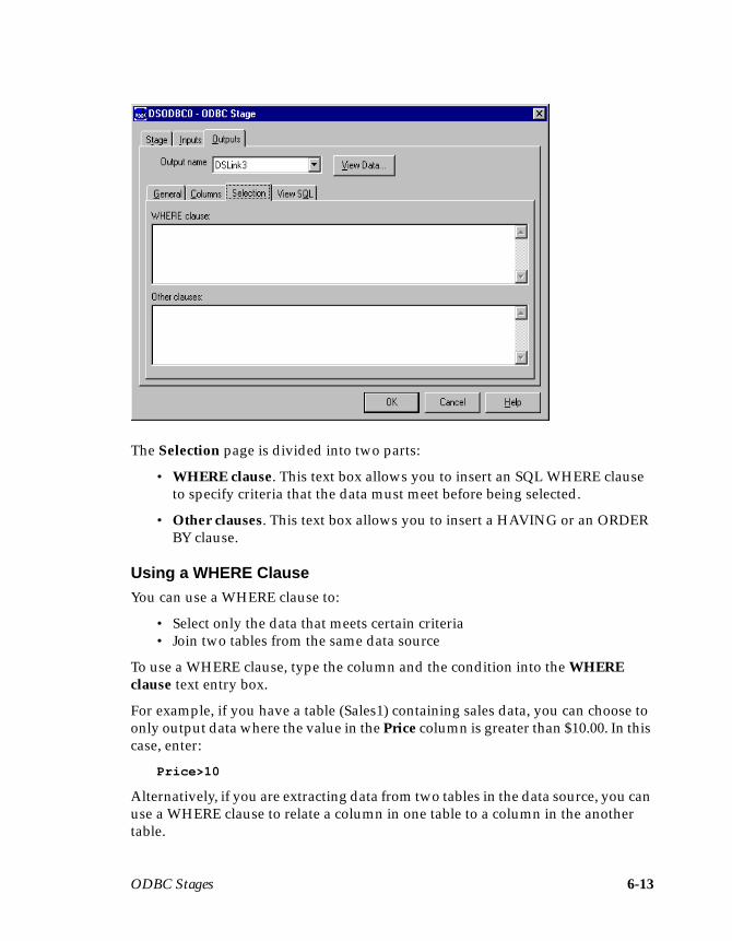
ODBC Stages 6-13
The Selection page is divided into two parts:
• WHERE clause. This text box allows you to insert an SQL WHERE clauseto specify criteria that the data must meet before being selected.
• Other clauses. This text box allows you to insert a HAVING or an ORDERBY clause.
Using a WHERE ClauseYou can use a WHERE clause to:
• Select only the data that meets certain criteria• Join two tables from the same data source
To use a WHERE clause, type the column and the condition into the WHEREclause text entry box.
For example, if you have a table (Sales1) containing sales data, you can choose toonly output data where the value in the Price column is greater than $10.00. In thiscase, enter:
Price>10
Alternatively, if you are extracting data from two tables in the data source, you canuse a WHERE clause to relate a column in one table to a column in the anothertable.

6-14 DataStage Developer’s Guide
For example, Table1 contains the columns Pcode, OrderNo, and SaleDate andTable2 contains Pcode, CustNo, Quantity, and Cost. You can use the WHEREclause to join the two tables together by the related column. In this case, the columnis Pcode and you enter:
Table1.Pcode = Table2.Pcode
Note: Only one column definition called Pcode is loaded or inserted into the gridon the Columns page.
You can also use a job parameter in the WHERE clause. For details on how todefine and use job parameters, see “Specifying Job Parameters” on page 5-32.
The SQL SELECT statement is automatically updated to include the WHEREclause. Click the View SQL tab to display the statement.
Using a HAVING ClauseIf you use an ODBC stage to aggregate data, you can use a HAVING clause tospecify conditions the grouped data must meet before it is selected. For more infor-mation about using an ODBC stage to aggregate data, see “Aggregating Data.”
To use a HAVING clause, enter the clause, column, and condition into the Otherclauses text entry box on the Selection page on the Outputs page.
For example, you could choose to only output summed quantities that are greaterthan or equal to 1000. In this case you enter:
HAVING SUM(QtySold)>=1000
The SQL SELECT statement is updated automatically. Click the View SQL tab todisplay the statement.
You can also use a job parameter in the HAVING clause. For details on how todefine and use job parameters, see “Specifying Job Parameters” on page 5-32.
Using an ORDER BY ClauseYou can sort data based on a chosen column by including an ORDER BY clause inthe SELECT statement. Records are sorted by data in the chosen column beforebeing output. You can specify a column name or a column position and whether tosort in ascending or descending order.
To use an ORDER BY clause, enter the clause, column, and condition into theOther clauses text entry box on the Selection page on the Outputs page.
For example, if your table contains a Name column, you may want to sort thecolumn alphabetically (A to Z). In this case you enter:
ORDER BY Name ASC
ODBC Stages 6-15
The SQL SELECT statement is updated automatically. Click the View SQL tab todisplay the statement.
Aggregating DataIf you are using a generated query, you can use an ODBC stage to aggregate dataat the source instead of using an intermediate Aggregator stage. By aggregatingdata you can add values in a particular column for all data records in a table. Thissummed total is then output from the stage.
You can aggregate data in two ways:
• Using an Aggregator stage. For more information, see Chapter 12, “Aggre-gator Stages.”
• Using an ODBC stage.
If you aggregate data using an ODBC stage, the columns to group by and sumtogether are also specified by the SQL SELECT statement. To specify the columnsto group by and summarize, you must edit the column definitions in the Columnsgrid on the Columns page. For more information about editing column defini-tions, see “Specifying Column Definitions” on page 5-18.
For example, if you have a sales database (Sales1) it may contain the followingcolumns: Product, SaleDate, and QtySold. If this database is updated daily, youhave a record of how many of each product are sold each day. However, if youwant to know how many of each product were sold since 01/01/96 you need tospecify a WHERE clause for the SaleDate and group (and summarize) the data.
Because you want the total for each product, you need to group all the occurrencesof the same value in the Product column and sum the value in the QtySoldcolumn.
To group by a column, click in the Group cell for the column definition you wantto group by and choose Yes from the drop-down list. In the example, you wouldchoose the Product column to edit
To summarize a column, edit the Derivation cell for the column you want to aggre-gate (using SUM or COUNT). The Derivation cell contains by default the name ofthe table and column in the format tablename.columnname. You can edit this cell toadd SUM or COUNT. In the example, you would edit the Derivation cell for theQtySold column. The resulting expression would be SUM(Sales1.QtySold).
When you group by or summarize columns, the SQL statement is automaticallyupdated to include the GROUP BY clause and the aggregation expression. To viewthe SQL statement, click the View SQL tab on the Outputs page.
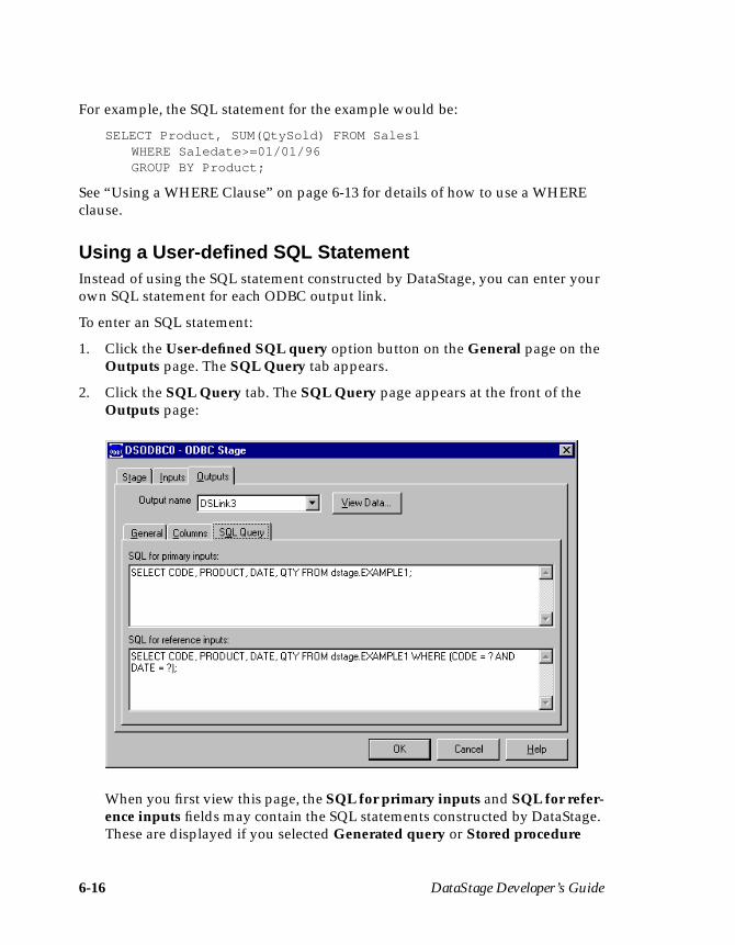
6-16 DataStage Developer’s Guide
For example, the SQL statement for the example would be:
SELECT Product, SUM(QtySold) FROM Sales1WHERE Saledate>=01/01/96GROUP BY Product;
See “Using a WHERE Clause” on page 6-13 for details of how to use a WHEREclause.
Using a User-defined SQL StatementInstead of using the SQL statement constructed by DataStage, you can enter yourown SQL statement for each ODBC output link.
To enter an SQL statement:
1. Click the User-defined SQL query option button on the General page on theOutputs page. The SQL Query tab appears.
2. Click the SQL Query tab. The SQL Query page appears at the front of theOutputs page:
When you first view this page, the SQL for primary inputs and SQL for refer-ence inputs fields may contain the SQL statements constructed by DataStage.These are displayed if you selected Generated query or Stored procedure
ODBC Stages 6-17
before selecting User-defined SQL query. You can modify or overwrite eachstatement to construct your own SQL query or call to a stored procedure.
The entries in these fields depend on whether the output is a primary input toa stage or a reference input to a Transformer stage:
• If the output is a primary input to any stage, whether or not it is a Trans-former stage, edit the SQL for primary inputs field. The SQL query mustcontain the same number of columns (and column names) as the SQL state-ment constructed by DataStage.
You must ensure that the table definitions for the output link are correctand represent the columns that are expected. The result set generated fromthis statement returns at least one row.
Note: If more than one result set is produced, only the first set is used.
• If the output is a reference input to a Transformer stage, edit the SQL forreference inputs field. The SQL query must contain the same number ofcolumns as the SQL statement constructed by DataStage. You must ensurethat the table definitions for the output link are correct and represent thecolumns that are expected. The statement must have the same number ofparameter values (?) as key columns on the link. The result set generatedby this statement or procedure contains at most one row.
3. Click OK to close the ODBC Stage dialog box. Changes are saved when yousave your job design.
Using a Stored ProcedureInstead of using a user-defined SQL statement or one constructed by DataStage,you can use a stored procedure to define the data you want to extract for eachODBC output link.
The way in which you use a stored procedure depends on whether the output linkis a primary input to another stage or a reference input to a Transformer stage.
Note: If the output from a stored procedure is used as a reference input to a Trans-former stage, you may experience some loss of performance when the jobis run.
Using a Stored Procedure for a Primary InputIf the ODBC output is a primary input to another stage in the job design, you mustspecify values for the stored procedure’s parameters. To use a stored procedure fora primary input:
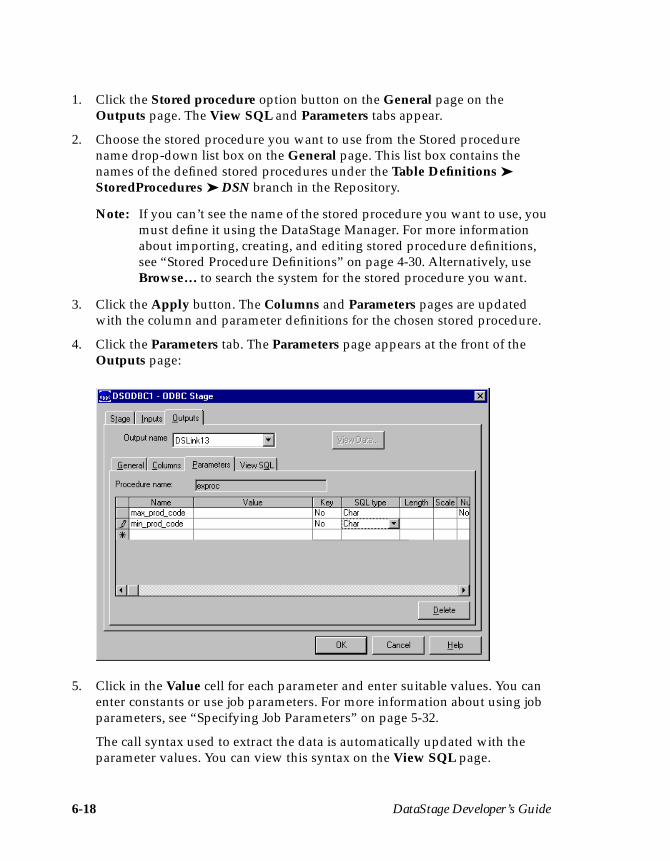
6-18 DataStage Developer’s Guide
1. Click the Stored procedure option button on the General page on theOutputs page. The View SQL and Parameters tabs appear.
2. Choose the stored procedure you want to use from the Stored procedurename drop-down list box on the General page. This list box contains thenames of the defined stored procedures under the Table Definitions ➤StoredProcedures ➤ DSN branch in the Repository.
Note: If you can’t see the name of the stored procedure you want to use, youmust define it using the DataStage Manager. For more informationabout importing, creating, and editing stored procedure definitions,see “Stored Procedure Definitions” on page 4-30. Alternatively, useBrowse… to search the system for the stored procedure you want.
3. Click the Apply button. The Columns and Parameters pages are updatedwith the column and parameter definitions for the chosen stored procedure.
4. Click the Parameters tab. The Parameters page appears at the front of theOutputs page:
5. Click in the Value cell for each parameter and enter suitable values. You canenter constants or use job parameters. For more information about using jobparameters, see “Specifying Job Parameters” on page 5-32.
The call syntax used to extract the data is automatically updated with theparameter values. You can view this syntax on the View SQL page.

ODBC Stages 6-19
6. Click OK to close the ODBC Stage dialog box. Changes are saved when yousave your job design.
When the job runs, the stored procedure is called once with the given parametervalues. The result set generated should contain at least one row.
Using a Stored Procedure for a Reference InputIf the ODBC output is a reference input to a Transformer stage, you must check thatthere is a parameter definition for each key column on the output link. When thejob is run, the parameter values are set to the values in the corresponding keycolumns. To use a stored procedure for a reference input:
1. Click the Stored procedure option button on the General page on theOutputs page. The View SQL and Parameters tabs appear.
2. Choose the stored procedure you want to use from the Stored procedurename drop-down list box. This list box contains the names of the definedstored procedures under the Table Definitions ➤ StoredProcedures ➤ DSNbranch in the Repository.
Note: If you can’t see the name of the stored procedure you want to use, youmust define it using the DataStage Manager. For more informationabout importing, creating, and editing stored procedure definitions,see “Stored Procedure Definitions” on page 4-30. Alternatively, useBrowse… to search the system for the stored procedure you want.
3. Click the Apply button. The Columns and Parameters pages are updatedwith the column and parameter definitions for the chosen stored procedure.
4. Click the Parameters tab. The Parameters page appears at the front of theOutputs page.
5. Check that there is a parameter definition for each key column specified onthe Columns page.
The call syntax used to extract the data is automatically updated. You can viewthis syntax on the View SQL page.
6. Click OK to close the ODBC Stage dialog box. Changes are saved when yousave your job design.
When the job runs, the stored procedure is called once for each row on the outputlink. The values in the key columns on the Columns page are bound to the storedprocedure parameters. The result set generated should contain at least one row.The columns in the result set should match the column definitions on the outputlink.

6-20 DataStage Developer’s Guide
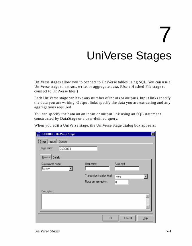
UniVerse Stages 7-1
7UniVerse Stages
UniVerse stages allow you to connect to UniVerse tables using SQL. You can use aUniVerse stage to extract, write, or aggregate data. (Use a Hashed File stage toconnect to UniVerse files.)
Each UniVerse stage can have any number of inputs or outputs. Input links specifythe data you are writing. Output links specify the data you are extracting and anyaggregations required.
You can specify the data on an input or output link using an SQL statementconstructed by DataStage or a user-defined query.
When you edit a UniVerse stage, the UniVerse Stage dialog box appears:
7-2 DataStage Developer’s Guide
This dialog box can have up to three pages (depending on whether there are inputsto and outputs from the stage):
• Stage. Displays the name of the stage you are editing. You can enter text todescribe the purpose of the stage in the Description field. The Generalpage defines the data source name. You can connect to a UniVerse datasource. For details on these connections types, see “Defining the Connec-tion” on page 7-2.
Note: You cannot change the name of the stage from this dialog box. Fordetails on how to change stage names, see “Renaming Stages” onpage 5-14.
• Inputs. This page is displayed only if you have an input link to this stage.Specifies the UniVerse table to use and the associated column definitionsfor each data input link. This page also specifies how data is written andcontains the SQL statement or call syntax used to write the data.
• Outputs. This page is displayed only if you have an output link to thisstage. Specifies the UniVerse tables to use and the associated column defini-tions for each data output link. This page also contains the SQL SELECTstatement or call syntax used to extract the data.
You must perform the following steps to edit a UniVerse stage:
1. Define the connection.
2. Define the data on the input links.
3. Define the data on the output links.
These steps are performed in the UniVerse Stage dialog box. Click OK to close thisdialog box. Changes are saved when you save the job design.
Defining the ConnectionThe UniVerse connection parameters are set on the General page on the Stagepage. To connect to a UniVerse data source, the data source must be configured inthe uvodbc.config file. For more information, see DataStage Administrator’s Guide.
UniVerse Stages 7-3
UniVerse Connection ParametersThe UniVerse connection parameters are set on the General and Details pages onthe Stage page. To connect to a UniVerse data source:
1. Choose the data source name from the Data source name drop-down list box.This drop-down list box contains all the data sources defined under the TableDefinitions ➤ UniVerse branch in the Repository.
Note: If the data source name you want is not listed, you can either enter thename in the Data source name field or define a table definition. Fordetails on how to import or create a table definition, see Chapter 4,“Setting Up a Project.”
You can also enter a job parameter in this field. For details on how to defineand use job parameters, see “Specifying Job Parameters” on page 5-32.
2. Enter the user name to use in the User name field. You can enter a job param-eter here, in the form #parameter#.
3. Enter the password to use in the Password field. You can enter a job param-eter here, in the form #parameter#, but it will be displayed as asterisks.
Note: If you are connecting to a remote UniVerse system using LANManager, or accessing a data file in localuv, you do not need to enter auser name and password. In the case of localuv data sources, the Username and Password fields are disabled.
4. Choose an appropriate transaction isolation level to use from the Transactionisolation level drop-down list box.
5. Enter an optional description of the UniVerse stage in the Description field.
6. If you are using a DSN other than localuv, click the Details tab. The Detailspage appears at the front of the Stage page.
7. Specify where to find the file to use by clicking the appropriate option button:
• Use account name. Enter the account name in the Account name field.
• Use directory path. Enter the directory path where the file is stored in theDirectory path field or use Browse… to search the system for a suitabledirectory. For more information about using Browse…, see “BrowsingServer Directories” on page 5-22.
Note: If you are accessing a file on localuv, you do not need to specify anaccount or directory path, and the Details tab is disabled.

7-4 DataStage Developer’s Guide
You can use a job parameter in any of the fields described in steps 1, 2, 3, 4, and 7.For details on how to define and use job parameters, see “Specifying Job Parame-ters” on page 5-32.
Defining UniVerse Input DataWhen you write data to a table in a UniVerse database, the UniVerse stage has aninput link. The properties of this link and the column definitions of the data aredefined on the Inputs page of the UniVerse Stage dialog box.
The Inputs page has the following field and up to five pages:
• Input name. The name of the input link. Choose the link you want to editfrom the Input name drop-down list box. This list box displays all the inputlinks to the UniVerse stage.
• General. This page is displayed by default. It contains the followingparameters:
– Table name. The name of the table or UniVerse file the data is written to.Choose the table or file from the Table name drop-down list box. This listbox contains all the tables defined under the Table Definitions ➤

UniVerse Stages 7-5
UniVerse ➤ Data source branch in the Repository. Data source is the datasource name chosen on the General page on the Stage page.
Note: If the table you want is not listed, you need to define a table defi-nition. For details on how to import or create a table definition, see“Table Definitions” on page 4-10. Alternatively, use Browse… todisplay the Table Definitions window and choose a suitable tabledefinition.
You can also enter a job parameter in this field. For details on how todefine and use job parameters, see “Specifying Job Parameters” onpage 5-32.
This field appears when the update action is not User-defined SQL.
– Update action. Specifies how the data is written. Choose the option youwant from the drop-down list box:
Clear the table, then insert rows. Deletes the contents of the table andadds the new rows.
Insert rows without clearing. Inserts the new rows in the table.
Replace existing rows completely. Deletes the existing rows, then addsthe new rows to the table.
Update existing rows only. Updates the existing data rows. Any rows inthe data that do not exist in the table are ignored.
Update existing rows or insert new ones. The existing data rows areupdated and new rows are added.
User-defined SQL. The data is written using a user-defined SQL state-ment. When you select this option, the View SQL page is replaced by theEnter SQL page.
– Create table in target database. Select this check box if you want to auto-matically create a table in the target database at run time. A table iscreated based on the defined column set for this stage. If you select thisbox, an additional page, Edit DDL, appears. This shows the SQLCREATE statement to be used for table generation.
– Description. Contains an optional description of the input link.
• Columns. Contains the column definitions for the data written to the tableor file. The column definitions are used in the order they appear in theColumns grid. For a description of how to enter and edit column defini-tions, see “Specifying Column Definitions” on page 5-18.
7-6 DataStage Developer’s Guide
• View SQL. Displays the SQL statement call syntax used to write the data.You cannot edit this statement, but you can use Copy to copy it to the Clip-board for use elsewhere. (This page is not displayed if the update action isUser-defined SQL.)
• Enter SQL. Displays the user-defined SQL statement. This page appearsonly when you set the update action to User-defined SQL.
• Edit DDL. This page appears if you have chosen to automatically generatea table at run time by selecting the Create table in target database checkbox on the General page. It displays the SQL CREATE statement that willbe used to create the table. To generate the statement, click the Create DDLbutton. DataStage will connect to the target database and generate thestatement. You can edit the statement on this page to make any requiredchanges. This page also allows you to specify that any existing table by thisname should be dropped first. If you do not select this option, and such atable already exists in the target database, then the create will fail.
Click the View Data… button to invoke the Data Browser. This enables you to lookat the data associated with the input link. For a description of the Data Browser, see“Using the Data Browser” on page 5-23.
Using a Generated QueryYou can write data to a UniVerse table using an SQL statement constructed byDataStage. When you specify the table and the column definitions to use, the SQLstatement is automatically constructed and can be viewed on the View SQL page.
To use a generated query:
1. Choose a table from the Table name drop-down list box on the General page.
2. Specify how you want the data to be written by choosing a suitable optionfrom the Update action drop-down list box. There are five options for a gener-ated query:
• Clear the table, then insert rows• Insert rows without clearing• Replace existing rows completely• Update existing rows only• Update existing rows or insert new ones
See page 7-5 for a description of each update action.
3. Enter an optional description of the input link in the Description field.
4. Click the Columns tab. The Columns page appears at the front of the Inputspage.
UniVerse Stages 7-7
5. Edit the Columns grid to specify column definitions for the columns youwant to write. For more information, see “Specifying Column Definitions” onpage 5-18.
The SQL statement is automatically constructed using your chosen updateaction and the columns you have specified. You can now optionally view thisSQL statement.
6. Click the View SQL tab. The View SQL page appears at the front of theInputs page.
7. Click OK to close the UniVerse Stage dialog box. Changes are saved whenyou save your job design.
Using a User-defined SQL StatementInstead of writing data using an SQL statement constructed by DataStage, you canenter your own SQL statement for each UniVerse input link.
To enter an SQL statement:
1. Choose User-defined SQL from the Update action drop-down list box on theGeneral page. The View SQL tab is replaced with the Enter SQL tab.
2. Click the Columns tab. The Columns page appears at the front of the Inputspage.
3. Edit the Columns grid to specify column definitions for the columns youwant to write. For more information, see “Specifying Column Definitions” onpage 5-18.
4. Click the Enter SQL tab. The Enter SQL page appears at the front of theInputs page.
5. Enter the SQL statement you want to use. This statement must contain thetable name, the type of update action you want to perform, and the columnsyou want to write.
Note: You must also ensure that the statement contains the correct number of? parameter markers. You must have a parameter marker for eachcolumn you have defined on the Columns page.
6. Click OK to close the UniVerse Stage dialog box. Changes are saved whenyou save your job design.
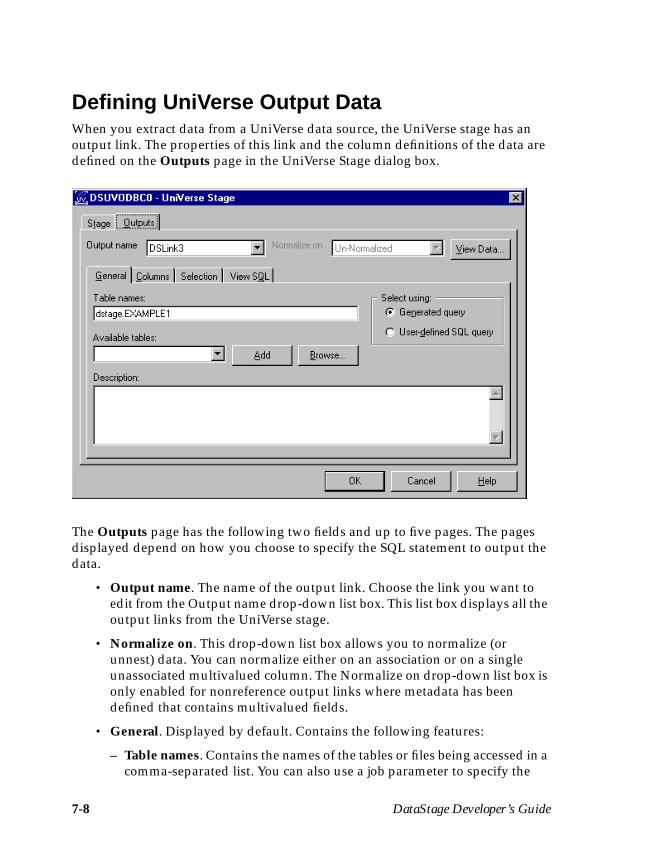
7-8 DataStage Developer’s Guide
Defining UniVerse Output DataWhen you extract data from a UniVerse data source, the UniVerse stage has anoutput link. The properties of this link and the column definitions of the data aredefined on the Outputs page in the UniVerse Stage dialog box.
The Outputs page has the following two fields and up to five pages. The pagesdisplayed depend on how you choose to specify the SQL statement to output thedata.
• Output name. The name of the output link. Choose the link you want toedit from the Output name drop-down list box. This list box displays all theoutput links from the UniVerse stage.
• Normalize on. This drop-down list box allows you to normalize (orunnest) data. You can normalize either on an association or on a singleunassociated multivalued column. The Normalize on drop-down list box isonly enabled for nonreference output links where metadata has beendefined that contains multivalued fields.
• General. Displayed by default. Contains the following features:
– Table names. Contains the names of the tables or files being accessed in acomma-separated list. You can also use a job parameter to specify the
UniVerse Stages 7-9
table name. For details on how to define and use job parameters, see“Specifying Job Parameters” on page 5-32.
– Available tables. Displays the names of the available tables or files thathave definitions in the Repository.
– Add. Adds a table from the Available tables drop-down list box to theTable names field.
– Generated query. Specifies that the data is extracted using an SQL state-ment constructed by DataStage. This is the default setting. When thisoption is selected, the Selection and View SQL pages appear.
– User-defined SQL query. Specifies that the data is extracted using a user-defined SQL query. When this option is selected, the SQL Query pageappears.
– Description. Contains an optional description of the output link.
– Browse… . Displays the Table Definitions window, allowing you tochoose a suitable table or stored procedure definition.
• Columns. Contains the column definitions for the data being output on thechosen link. For a description of how to enter and edit column definitions,see “Specifying Column Definitions” on page 5-18. Also specifies whichcolumns are aggregated.
• Selection. Contains optional SQL SELECT clauses for the conditionalextraction of data. This page appears when you select Generated query.
• View SQL. Displays the SQL statement used to extract the data from thechosen table or tables. This page appears when you select Generatedquery. The SQL statement exists in two forms and you can choose whichone to display:
– SQL for reference inputs. Choose this to view the SQL statement usedwhen this link is a reference input to a Transformer stage.
– SQL for primary inputs. Choose this to view the SQL statement used inall other cases.
You cannot edit the SQL statement, but you can use Copy to copy it to theClipboard for use elsewhere.
• SQL Query. Contains a user-defined SQL query. This page appears whenyou select User-defined SQL query. This page is divided into two areas:
– SQL for primary inputs. Contains a user-defined SQL query for a linkthat is a primary input to a Transformer stage, or an input to any othertype of stage.
7-10 DataStage Developer’s Guide
– SQL for reference inputs. Contains a user-defined SQL query for a linkthat is a reference input to a Transformer stage.
Click the View Data… button to invoke the Data Browser. This enables you to lookat the data associated with the input link. For a description of the Data Browser, see“Using the Data Browser” on page 5-23.
Key FieldsThe column definitions for output links contain a key field. Key fields are used tojoin primary and reference inputs to a Transformer stage. For details on how keyfields are specified and used, see “Defining Input Column Key Expressions”onpage 11-9.
Using a Generated QueryWhen you select Generated query, data is extracted from a UniVerse data sourceusing an SQL SELECT statement constructed by DataStage. SQL SELECT state-ments have the following syntax:
SELECT clause FROM clause[WHERE clause][GROUP BY clause][HAVING clause][ORDER BY clause];
When you specify the tables to use and the columns to be output from the UniVersestage, the SQL SELECT statement is automatically constructed and can be viewedby clicking the View SQL tab on the Outputs page.
Note: The View SQL page appears only when you select Generated query on theGeneral page on the Outputs page.
For example, if you extract the columns Name, Address, and Phone from a tablecalled Table1, the SQL statement displayed on the View SQL page is:
SELECT Name, Address, Phone FROM Table1;
The SELECT and FROM clauses are the minimum required and are automaticallygenerated by DataStage. However, you can use any of these SQL SELECT clauses:
SELECT clause Specifies the columns to select from the database.
FROM clause Specifies the tables containing the selected columns.
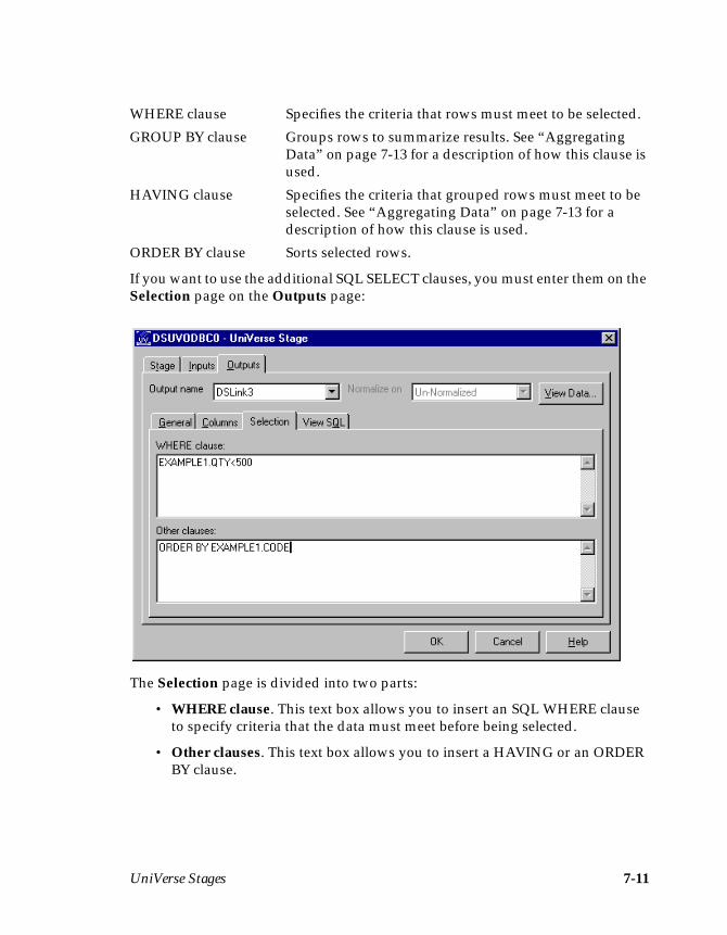
UniVerse Stages 7-11
If you want to use the additional SQL SELECT clauses, you must enter them on theSelection page on the Outputs page:
The Selection page is divided into two parts:
• WHERE clause. This text box allows you to insert an SQL WHERE clauseto specify criteria that the data must meet before being selected.
• Other clauses. This text box allows you to insert a HAVING or an ORDERBY clause.
WHERE clause Specifies the criteria that rows must meet to be selected.
GROUP BY clause Groups rows to summarize results. See “AggregatingData” on page 7-13 for a description of how this clause isused.
HAVING clause Specifies the criteria that grouped rows must meet to beselected. See “Aggregating Data” on page 7-13 for adescription of how this clause is used.
ORDER BY clause Sorts selected rows.
7-12 DataStage Developer’s Guide
Using a WHERE ClauseYou can use a WHERE clause to:
• Select only the data that meets certain criteria• Join two tables from the same data source
To use a WHERE clause, type the column and the condition into the WHEREclause text entry box.
For example, if you have a table (Sales1) containing sales data, you can choose toonly output data where the value in the Price column is greater than $10.00. In thiscase, enter:
Price>10
Alternatively, if you are extracting data from two tables in the data source, you canuse a WHERE clause to relate a column in one table to a column in the anothertable.
For example, Table1 contains the columns Pcode, OrderNo, and SaleDate andTable2 contains Pcode, CustNo, Quantity, and Cost. You can use the WHEREclause to join the two tables together by the related column. In this case, the columnis Pcode and you enter:
Table1.Pcode = Table2.Pcode
Note: Only one column definition called Pcode is loaded or inserted into the gridon the Columns page.
You can also use a job parameter in the WHERE clause. For details on how todefine and use job parameters, see “Specifying Job Parameters” on page 5-32.
The SQL SELECT statement is automatically updated to include the WHEREclause. Click the View SQL tab to display the statement.
Using a HAVING ClauseIf you use a UniVerse stage to aggregate data, you can use a HAVING clause tospecify conditions the grouped data must meet before it is selected. For more infor-mation about using a UniVerse stage to aggregate data, see “Aggregating Data” onpage 7-13.
To use a HAVING clause, enter the clause, column, and condition into the Otherclauses text entry box on the Selection page on the Outputs page.
For example, you could choose to only output summed quantities that are greaterthan or equal to 1000. In this case you enter:
HAVING SUM(QtySold)>=1000
UniVerse Stages 7-13
The SQL SELECT statement is updated automatically. Click the View SQL tab todisplay the statement.
You can also use a job parameter in the HAVING clause. For details on how todefine and use job parameters, see “Specifying Job Parameters” on page 5-32.
Using an ORDER BY ClauseYou can sort data based on a chosen column by including an ORDER BY clause inthe SELECT statement. Records are sorted by data in the chosen column beforebeing output. You can specify a column name or a column position and whether tosort in ascending or descending order.
To use an ORDER BY clause, enter the clause, column, and condition into theOther clauses text entry box on the Selection page on the Outputs page.
For example, if your table contains a Name column, you may want to sort thecolumn alphabetically (A to Z). In this case you enter:
ORDER BY Name ASC
The SQL SELECT statement is updated automatically. Click the View SQL tab todisplay the statement.
Aggregating DataIf you are using a generated query, you can use a UniVerse stage to aggregate dataat the source instead of using an intermediate Aggregator stage. By aggregatingdata you can add values in a particular column for all data records in a table. Thissummed total is then output from the stage.
You can aggregate data in two ways:
• Using an Aggregator stage. For more information, see Chapter 12, “Aggre-gator Stages.”
• Using a UniVerse stage.
If you aggregate data using a UniVerse stage, the columns to group by and sumtogether are also specified by the SQL SELECT statement. To specify the columnsto group by and summarize, you must edit the column definitions in the Columnsgrid on the Columns page. For more information about editing column defini-tions, see “Specifying Column Definitions” on page 5-18.

7-14 DataStage Developer’s Guide
For example, if you have a sales database (Sales1) it may contain the followingcolumns: Product, SaleDate, and QtySold. If this database is updated daily, youhave a record of how many of each product are sold each day. However, if youwant to know how many of each product were sold since 01/01/96 you need tospecify a WHERE clause for the SaleDate and group (and summarize) the data.
Because you want the total for each product, you need to group all the occurrencesof the same value in the Product column and sum the value in the QtySoldcolumn.
To group by a column, click in the Group cell for the column definition you wantto group by and choose Yes from the drop-down list. In the example, you wouldchoose the Product column to edit
To summarize a column, click in the Derivation cell for the column you want toaggregate (using SUM or COUNT). The Derivation cell contains by default thename of the table and column in the format tablename.columnname. You can edit thiscell to add SUM or COUNT. In the example, you would edit the Derivation cell forthe QtySold column. The resulting expression would be SUM(Sales1.QtySold).
When you group by or summarize columns, the SQL statement is automaticallyupdated to include the GROUP BY clause and the aggregation expression. To viewthe SQL statement, click the View SQL tab on the Outputs page.
For example, the SQL statement for the example would be:
SELECT Product, SUM(QtySold) FROM Sales1WHERE Saledate>=01/01/96GROUP BY Product;
See “Using a WHERE Clause” on page 7-12 for details of how to use a WHEREclause.
Using a User-defined SQL StatementInstead of using the SQL statement constructed by DataStage, you can enter yourown SQL statement for each UniVerse output link.
To enter an SQL statement:
1. Click the User-defined SQL query option on the General page on theOutputs page. The SQL Query tab appears.
2. Click the SQL Query tab. The SQL Query page appears at the front of theOutputs page:
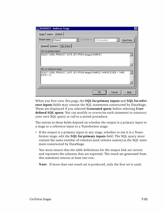
UniVerse Stages 7-15
When you first view this page, the SQL for primary inputs and SQL for refer-ence inputs fields may contain the SQL statements constructed by DataStage.These are displayed if you selected Generated query before selecting User-defined SQL query. You can modify or overwrite each statement to constructyour own SQL query or call to a stored procedure.
The entries in these fields depend on whether the output is a primary input toa stage or a reference input to a Transformer stage:
• If the output is a primary input to any stage, whether or not it is a Trans-former stage, edit the SQL for primary inputs field. The SQL query mustcontain the same number of columns (and column names) as the SQL state-ment constructed by DataStage.
You must ensure that the table definitions for the output link are correctand represent the columns that are expected. The result set generated fromthis statement returns at least one row.
Note: If more than one result set is produced, only the first set is used.

7-16 DataStage Developer’s Guide
• If the output is a reference input to a Transformer stage, edit the SQL forreference inputs field. The SQL query must contain the same number ofcolumns as the SQL statement constructed by DataStage. You must ensurethat the table definitions for the output link are correct and represent thecolumns that are expected. The statement must have the same number ofparameter values (?) as key columns on the link. The result set generatedby this statement or procedure contains at most one row.
3. Click OK to close the UniVerse Stage dialog box. Changes are saved whenyou save your job design.
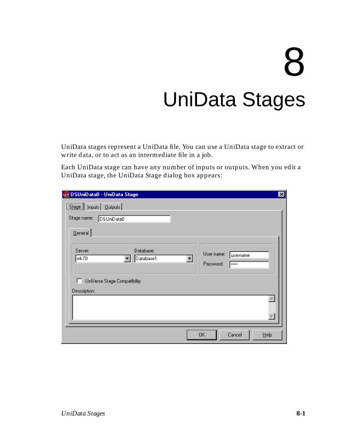
UniData Stages 8-1
8UniData Stages
UniData stages represent a UniData file. You can use a UniData stage to extract orwrite data, or to act as an intermediate file in a job.
Each UniData stage can have any number of inputs or outputs. When you edit aUniData stage, the UniData Stage dialog box appears:
8-2 DataStage Developer’s Guide
This dialog box can have up to three pages (depending on whether there are inputsto and outputs from the stage):
• Stage. Displays the name of the stage you are editing. This page has aGeneral page, where you can enter text to describe the purpose of the stagein the Description field and specify where the data files are by selecting adata source name and supplying logon details for the server where the datasource is located.
– Server. Choose a server name from the drop-down list, or type a servername. The list is populated from the Table Definitions ➤ UniDatabranch in the Manager. You can use a job parameter in this field. Fordetails on how to define and use job parameters, see “Specifying JobParameters” on page 5-32.
– Database. Choose a database from the drop-down list, or type a databasename. The list is populated from the Table Definitions ➤ UniDatabranch in the Manager. You can use a job parameter in this field.
– User name. Enter the user name to be used for logging on to the server.You can use a job parameter in this field.
– Password. Enter the password to be used for logging on to the server. Youcan use a job parameter in this field.
– UniVerse Stage Compatibility. Select this check box to ensure that anyjob conversions will work correctly. With this option selected, the date ortime will be represented in ISO format (depending on the Extended type)and numerics will be scaled according to the metadata. (The job conver-sion utility is a special standalone tool – it is not available within theDataStage Designer.)
Note: You cannot change the name of the stage from this dialog box. Fordetails on how to change stage names, see “Renaming Stages” onpage 5-14.
• Inputs. This page is displayed only if you have an input link to this stage.Specifies the data file to use and the associated column definitions for eachdata input link. This page also specifies how data is written to the data file.
• Outputs. This page is displayed only if you have an output link to thisstage. Specifies the data file to use and the associated column definitionsfor each data output link.
Click OK to close this dialog box. Changes are saved when you save the job.
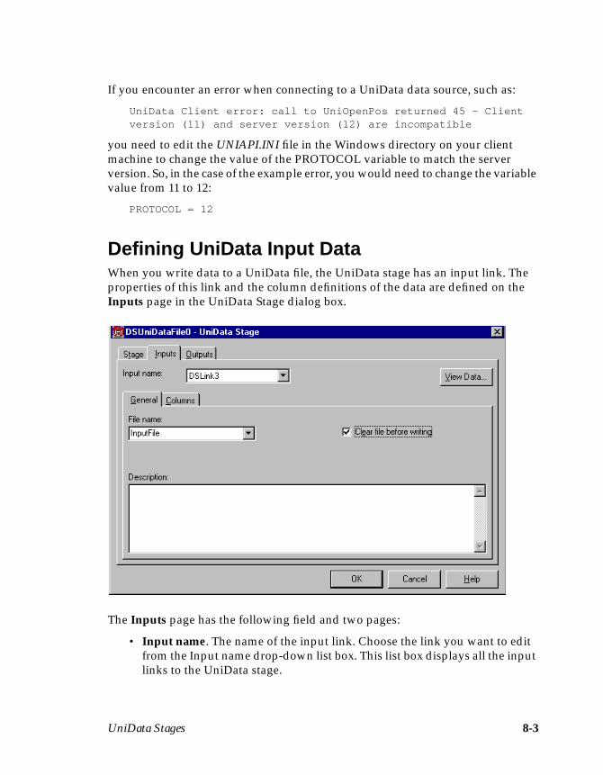
UniData Stages 8-3
If you encounter an error when connecting to a UniData data source, such as:
UniData Client error: call to UniOpenPos returned 45 - Clientversion (11) and server version (12) are incompatible
you need to edit the UNIAPI.INI file in the Windows directory on your clientmachine to change the value of the PROTOCOL variable to match the serverversion. So, in the case of the example error, you would need to change the variablevalue from 11 to 12:
PROTOCOL = 12
Defining UniData Input DataWhen you write data to a UniData file, the UniData stage has an input link. Theproperties of this link and the column definitions of the data are defined on theInputs page in the UniData Stage dialog box.
The Inputs page has the following field and two pages:
• Input name. The name of the input link. Choose the link you want to editfrom the Input name drop-down list box. This list box displays all the inputlinks to the UniData stage.
8-4 DataStage Developer’s Guide
• General. Displayed by default and contains the following fields andoptions:
– File name. The name of the file the data is written to. You can use a jobparameter to represent the file created during run time (see page 5-32 formore details), choose the file from the File name drop-down list box, orenter a file name. This list box contains all the files defined under theTable Definitions ➤ UniData ➤ Server ➤ Database branch in theManager.
Note: If the file you want is not listed, you may need to define a tabledefinition. For details on how to create a table definition, seeChapter 4, “Setting Up a Project.”
– Clear file before writing. If you select this check box, the existing file iscleared and new data records are written to the empty file. This check boxis cleared by default.
– Description. Contains an optional description of the input link.
• Columns. Contains the column definitions for the data written to the file.For a description of how to enter and edit column definitions, see “Speci-fying Column Definitions” on page 5-18.
Note: If you are using metadata that does not specify column positions,then the first column definition describes the UniData file’s key field.The remaining columns are ordered according to their position in thefile. Do not reorder the column definitions in the grid unless you arecertain you understand the consequences of your action.
Click the View Data… button to invoke the Data Browser. This enables you to lookat the data associated with the input link. For a description of the Data Browser, see“Using the Data Browser” on page 5-23.
Defining UniData Output DataWhen you extract data from a UniData file, the UniData stage has an output link.The properties of this link and the column definitions of the data are defined on theOutputs page in the UniData Stage dialog box.
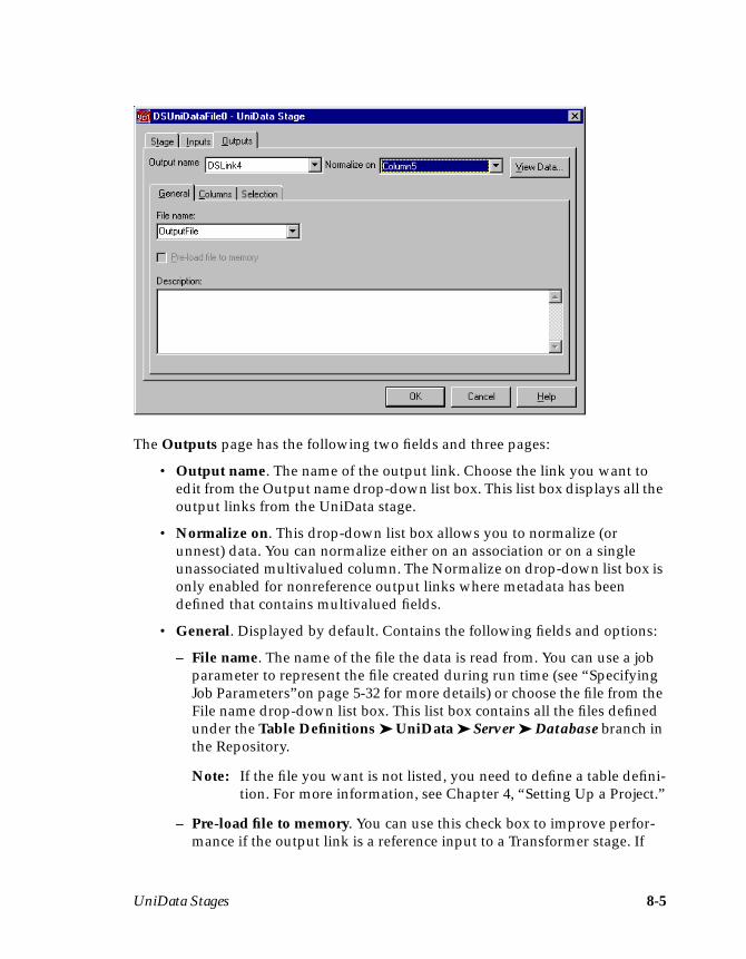
UniData Stages 8-5
The Outputs page has the following two fields and three pages:
• Output name. The name of the output link. Choose the link you want toedit from the Output name drop-down list box. This list box displays all theoutput links from the UniData stage.
• Normalize on. This drop-down list box allows you to normalize (orunnest) data. You can normalize either on an association or on a singleunassociated multivalued column. The Normalize on drop-down list box isonly enabled for nonreference output links where metadata has beendefined that contains multivalued fields.
• General. Displayed by default. Contains the following fields and options:
– File name. The name of the file the data is read from. You can use a jobparameter to represent the file created during run time (see “SpecifyingJob Parameters”on page 5-32 for more details) or choose the file from theFile name drop-down list box. This list box contains all the files definedunder the Table Definitions ➤ UniData ➤ Server ➤ Database branch inthe Repository.
Note: If the file you want is not listed, you need to define a table defini-tion. For more information, see Chapter 4, “Setting Up a Project.”
– Pre-load file to memory. You can use this check box to improve perfor-mance if the output link is a reference input to a Transformer stage. If

8-6 DataStage Developer’s Guide
selected, the UniData file is read into memory when the job is run. Thischeck box is cleared by default.
– Description. Contains an optional description of the output link.
• Columns. Contains the column definitions for the data on the chosenoutput link. For a description of how to enter or edit column definitions,see “Specifying Column Definitions” on page 5-18.
Note: If you are using metadata that does not specify column positions,then the first column definition describes the UniData file’s key field.The remaining columns are ordered according to their position in thefile. Do not reorder the column definitions in the grid unless you arecertain you understand the consequences of your action.
• Selection. Contains optional SQL SELECT clauses for the conditionalextraction of data from a file.
Click the View Data… button to invoke the Data Browser. This enables you to lookat the data associated with the output link. For a description of the Data Browser,see “Using the Data Browser” on page 5-23.
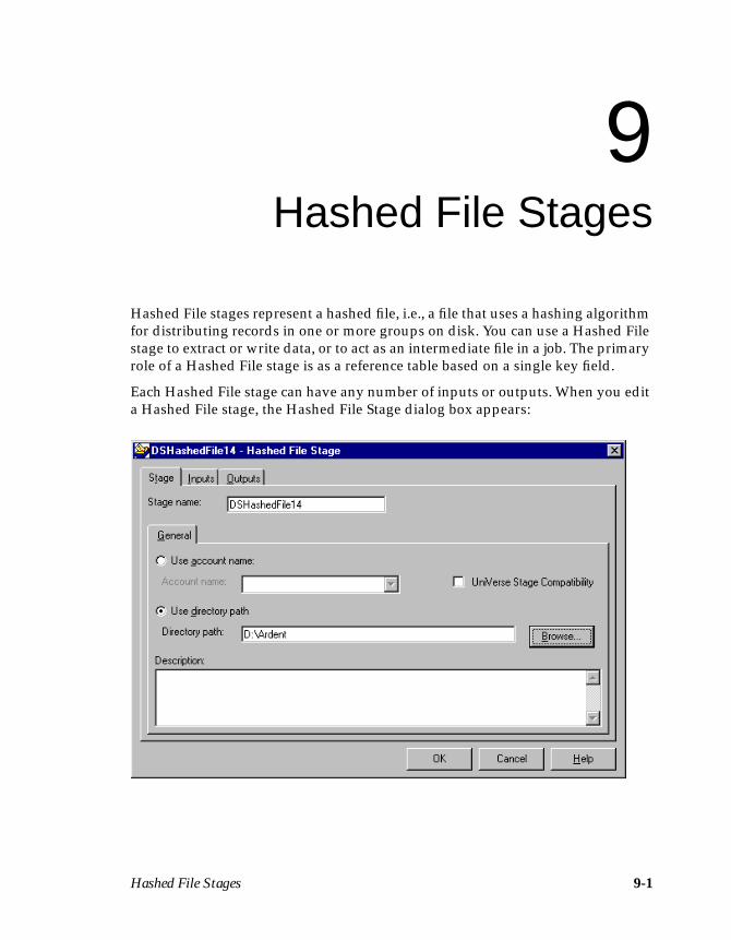
Hashed File Stages 9-1
9Hashed File Stages
Hashed File stages represent a hashed file, i.e., a file that uses a hashing algorithmfor distributing records in one or more groups on disk. You can use a Hashed Filestage to extract or write data, or to act as an intermediate file in a job. The primaryrole of a Hashed File stage is as a reference table based on a single key field.
Each Hashed File stage can have any number of inputs or outputs. When you edita Hashed File stage, the Hashed File Stage dialog box appears:

9-2 DataStage Developer’s Guide
This dialog box can have up to three pages (depending on whether there are inputsto and outputs from the stage):
• Stage. Displays the name of the stage you are editing. This page has aGeneral page, where you can enter text to describe the purpose of the stagein the Description field and specify where the data files are by clicking oneof the option buttons:
– Use account name. If you choose this option, you must choose the nameof the account from the Account name drop-down list box. This list boxcontains all the accounts defined under the Table Definitions ➤ Hashedbranch in the DataStage Manager. If the account you want is not listed,you need to define a table definition. For details on how to create a tabledefinition, see Chapter 4, “Setting Up a Project.” Alternatively, you canenter an account name or use a job parameter. For details on how to defineand use job parameters, see “Specifying Job Parameters” on page 5-32.
– Use directory path. If you choose this option, you must specify a direc-tory path containing the data file. The directory must be a UniVerseaccount and is used for UniVerse accounts that do not appear in theUV.ACCOUNT file. The directory is specified in the Directory path field.You can enter a path directly, click Browse… to search the system for asuitable directory, or use a job parameter. For more information aboutusing Browse…, see “Browsing Server Directories” on page 5-22.
– UniVerse Stage Compatibility. Select this check box to ensure that anyjob conversions will work correctly. With this option selected, the date ortime will be represented in ISO format (depending on the Extended type)and numerics will be scaled according to the metadata. (The job conver-sion utility is a special standalone tool – it is not available within theDataStage Designer.)
Note: You cannot change the name of the stage from this dialog box. Fordetails on how to change stage names, see “Renaming Stages” onpage 5-14.
• Inputs. This page is only displayed if you have an input link to this stage.Specifies the data file to use and the associated column definitions for eachdata input link. This page also specifies how data is written to the data file.
• Outputs. This page is only displayed if you have an output link to thisstage. Specifies the data file to use and the associated column definitionsfor each data output link.
Click OK to close this dialog box. Changes are saved when you save the job.
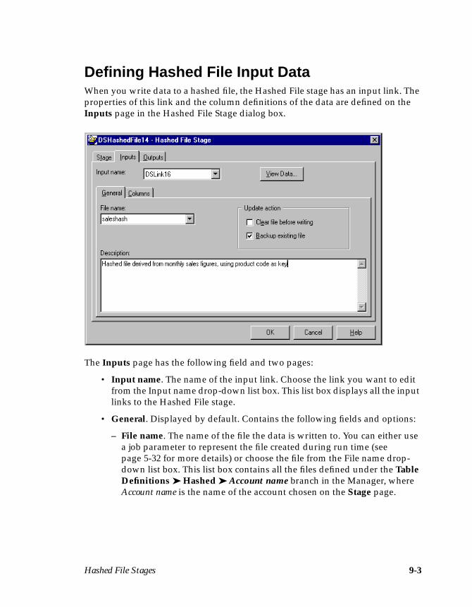
Hashed File Stages 9-3
Defining Hashed File Input DataWhen you write data to a hashed file, the Hashed File stage has an input link. Theproperties of this link and the column definitions of the data are defined on theInputs page in the Hashed File Stage dialog box.
The Inputs page has the following field and two pages:
• Input name. The name of the input link. Choose the link you want to editfrom the Input name drop-down list box. This list box displays all the inputlinks to the Hashed File stage.
• General. Displayed by default. Contains the following fields and options:
– File name. The name of the file the data is written to. You can either usea job parameter to represent the file created during run time (seepage 5-32 for more details) or choose the file from the File name drop-down list box. This list box contains all the files defined under the TableDefinitions ➤ Hashed ➤ Account name branch in the Manager, whereAccount name is the name of the account chosen on the Stage page.
9-4 DataStage Developer’s Guide
Note: If the file you want is not listed, you may need to define a table defi-nition. For details on how to create a table definition, see Chapter 4,“Setting Up a Project.”
– Clear file before writing. If you select this check box, the existing file iscleared and new data records are written to the empty file. This check boxis cleared by default.
– Backup existing file. If you select this check box, a backup copy of theexisting file is made before the new data records are written to the file.The backup can be used to reset the file if a job is stopped or aborted atrun time. See DataStage Operator’s Guide for more details. This check boxis cleared by default.
– Description. Contains an optional description of the input link.
• Columns. Contains the column definitions for the data written to the file.For a description of how to enter and edit column definitions, see “Speci-fying Column Definitions” on page 5-18.
Note: If you are using metadata that does not specify column positions,then the first column definition describes the hashed file’s key field.The remaining columns are ordered according to their position in thefile. Do not reorder the column definitions in the grid unless you arecertain you understand the consequences of your action.
Click the View Data… button to invoke the Data Browser. This enables you to lookat the data associated with the input link. For a description of the Data Browser, see“Using the Data Browser” on page 5-23.
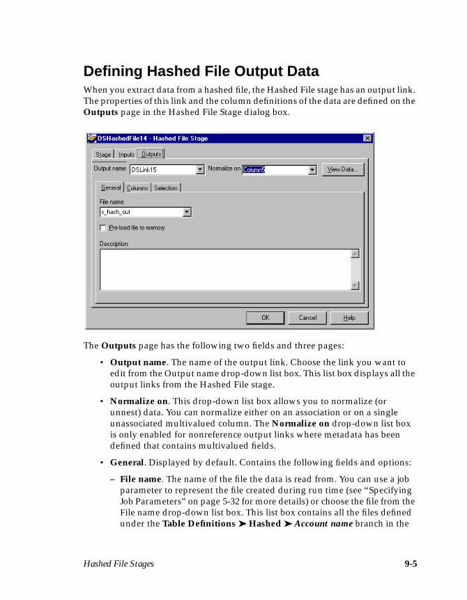
Hashed File Stages 9-5
Defining Hashed File Output DataWhen you extract data from a hashed file, the Hashed File stage has an output link.The properties of this link and the column definitions of the data are defined on theOutputs page in the Hashed File Stage dialog box.
The Outputs page has the following two fields and three pages:
• Output name. The name of the output link. Choose the link you want toedit from the Output name drop-down list box. This list box displays all theoutput links from the Hashed File stage.
• Normalize on. This drop-down list box allows you to normalize (orunnest) data. You can normalize either on an association or on a singleunassociated multivalued column. The Normalize on drop-down list boxis only enabled for nonreference output links where metadata has beendefined that contains multivalued fields.
• General. Displayed by default. Contains the following fields and options:
– File name. The name of the file the data is read from. You can use a jobparameter to represent the file created during run time (see “SpecifyingJob Parameters” on page 5-32 for more details) or choose the file from theFile name drop-down list box. This list box contains all the files definedunder the Table Definitions ➤ Hashed ➤ Account name branch in the
9-6 DataStage Developer’s Guide
Repository, where Account name is the name of the account chosen on theStage page.
Note: If the file you want is not listed, you need to define a table defini-tion. For more information, see Chapter 4, “Setting Up a Project.”
– Pre-load file to memory. You can use this check box to improve perfor-mance if the output link is a reference input to a Transformer stage. Ifselected, the hashed file is read into memory when the job is run. Thischeck box is cleared by default.
– Description. Contains an optional description of the output link.
• Columns. Contains the column definitions for the data on the chosenoutput link. For a description of how to enter or edit column definitions,see “Specifying Column Definitions” in page 5-18.
Note: If you are using metadata that does not specify column positions,then the first column definition describes the hashed file’s key field.The remaining columns are ordered according to their position in thefile. Do not reorder the column definitions in the grid unless you arecertain you understand the consequences of your action.
• Selection. Contains optional SQL SELECT clauses for the conditionalextraction of data from a file. This page is only available if you have speci-fied the hashed file by account name, rather than directory path, on theStage page.
Click the View Data… button to invoke the Data Browser. This enables you to lookat the data associated with the output link. For a description of the Data Browser,see “Using the Data Browser” on page 5-23.
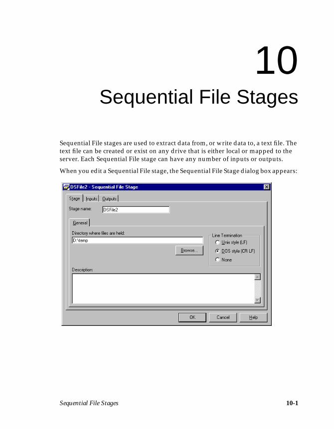
Sequential File Stages 10-1
10Sequential File Stages
Sequential File stages are used to extract data from, or write data to, a text file. Thetext file can be created or exist on any drive that is either local or mapped to theserver. Each Sequential File stage can have any number of inputs or outputs.
When you edit a Sequential File stage, the Sequential File Stage dialog box appears:
10-2 DataStage Developer’s Guide
This dialog box can have up to three pages (depending on whether there are inputsto and outputs from the stage):
• Stage. Displays the name of the stage you are editing. You can enter anoptional description of the stage in the Description field. You must choosethe directory containing the files you want to read or write to.
The operating system directory is specified in the Directory where files areheld field. You can edit this field in two ways:
– Enter the directory path in the field. You can also include a job parameterin the directory path. For details of how to define and use job parameters,see “Specifying Job Parameters” on page 5-32.
– Click Browse… . The Browse directories dialog box appears. Expand thefile system to display the directory you want. Highlight the directory andclick OK. The Directory where files are held field is updated with thechosen directory. For more information about using Browse…, see“Browsing Server Directories” on page 5-22.
The line termination options let you set the type of line terminator to use inthe Sequential File stage. By default, line termination matches the typeused on your DataStage server. To change the value, select one of Unixstyle (LF), DOS style (CR LF), or None.
Note: You cannot change the name of the stage from this dialog box. Fordetails on changing stage names, see “Renaming Stages” onpage 5-14.
• Inputs. Contains information about the file formats and column definitionsfor each data input link. This page is displayed only if you have an inputlink to this stage.
• Outputs. Contains information about the file format and column defini-tions for the data output links. This page is displayed only if you have anoutput link to this stage.
Click OK to close this dialog box. Changes are saved when you save the job.
Defining Sequential File Input DataWhen you write data to a sequential file, the Sequential File stage has an input link.The properties of this link and the column definitions of the data are defined on theInputs page in the Sequential File Stage dialog box.
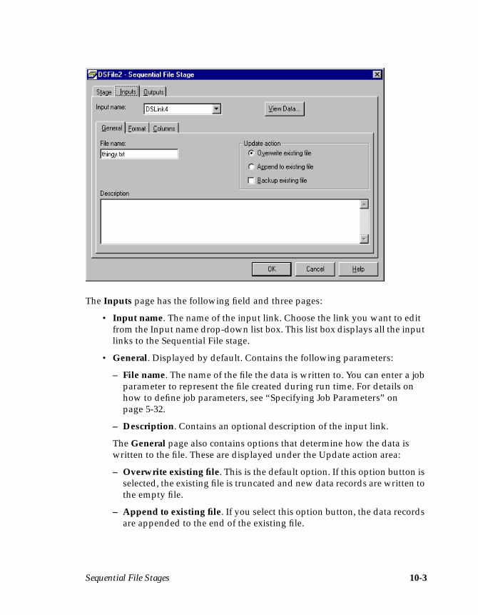
Sequential File Stages 10-3
The Inputs page has the following field and three pages:
• Input name. The name of the input link. Choose the link you want to editfrom the Input name drop-down list box. This list box displays all the inputlinks to the Sequential File stage.
• General. Displayed by default. Contains the following parameters:
– File name. The name of the file the data is written to. You can enter a jobparameter to represent the file created during run time. For details onhow to define job parameters, see “Specifying Job Parameters” onpage 5-32.
– Description. Contains an optional description of the input link.
The General page also contains options that determine how the data iswritten to the file. These are displayed under the Update action area:
– Overwrite existing file. This is the default option. If this option button isselected, the existing file is truncated and new data records are written tothe empty file.
– Append to existing file. If you select this option button, the data recordsare appended to the end of the existing file.
10-4 DataStage Developer’s Guide
– Backup existing file. If you select this check box, a backup copy of theexisting file is taken. The new data records are written based on whetheryou chose to append to or overwrite the existing file.
Note: The backup can be used to reset the file if a job is stopped oraborted at run time. See DataStage Operator’s Guide for moredetails.
• Format. Contains parameters that determine the format of the data in thefile. There are three check boxes:
– Fixed-width columns. If you select this check box, the data is written tothe file in fixed-width columns. The width of each column is specified bythe SQL display size (set in the Display column in the Columns grid).This option is cleared by default.
– First line is column names. Select this check box if the first row of data inthe file contains column names. This option is cleared by default, that is,the first row in the file contains data.
– Omit last new-line. Select this check box if you want to remove the lastnewline character in the file. This option is cleared by default, i.e., thenewline character is not removed.
There are four fields on the Format page:
– Delimiter. Contains the delimiter that separates the data fields in the file.By default this field contains a comma. You can enter a single printablecharacter (other than a digit) or a number from 0 through 255 to representthe ASCII code for the character you want to use.
– Quote character. Contains the character used to enclose a data value thatcontains the delimiter character as data. By default this field contains adouble quotation mark. You can enter a single printable character (otherthan a digit) or a number from 1 through 255 to represent the ASCII codefor the character you want to use. You can suppress the quote characterby entering 0.
– Spaces between columns. This field is only active when you select theFixed-width columns check box. Contains a number to represent thenumber of spaces used between columns.
– NULL string. Contains characters that are written to the file when acolumn contains an SQL NULL.
• Columns. Contains the column definitions for the data on the chosen inputlink. For a description of how to enter and edit column definitions, see“Specifying Column Definitions”on page 5-18.
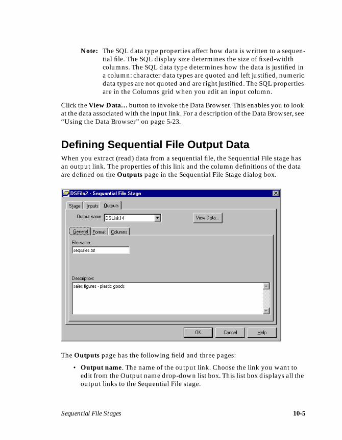
Sequential File Stages 10-5
Note: The SQL data type properties affect how data is written to a sequen-tial file. The SQL display size determines the size of fixed-widthcolumns. The SQL data type determines how the data is justified ina column: character data types are quoted and left justified, numericdata types are not quoted and are right justified. The SQL propertiesare in the Columns grid when you edit an input column.
Click the View Data… button to invoke the Data Browser. This enables you to lookat the data associated with the input link. For a description of the Data Browser, see“Using the Data Browser” on page 5-23.
Defining Sequential File Output DataWhen you extract (read) data from a sequential file, the Sequential File stage hasan output link. The properties of this link and the column definitions of the dataare defined on the Outputs page in the Sequential File Stage dialog box.
The Outputs page has the following field and three pages:
• Output name. The name of the output link. Choose the link you want toedit from the Output name drop-down list box. This list box displays all theoutput links to the Sequential File stage.
10-6 DataStage Developer’s Guide
• General. Displayed by default. There are two fields:
– File name. The name of the file the data is extracted from. You can entera job parameter to represent the file created during run time. For detailson how to define job parameters, see “Specifying Job Parameters” onpage 5-32.
– Description. Contains an optional description of the output link.
• Format. Contains parameters that determine the format of the data in thefile. There are two check boxes:
– Fixed-width columns. If you select this check box, the data is extractedfrom the file in fixed-width columns. The width of each column is speci-fied by the SQL display size (set in the Display column in the Columnsgrid). This option is cleared by default.
– First line is column names. Select this check box if the first row of data inthe file contains column names. This option is cleared by default, that is,the first row in the file contains data.
There are four fields on the Format page:
– Delimiter. Contains the delimiter that separates the data fields in the file.By default this field contains a comma. You can enter a single printablecharacter (other than a digit) or a number 0 through 255 to represent theASCII code for the character you want to use.
– Quote character. Contains the character used to enclose a data value thatcontains the delimiter character as data. By default this field contains adouble quotation mark. You can enter a single printable character (otherthan a digit) or a number 0 through 255 to represent the ASCII code forthe character you want to use.
– Spaces between columns. This field is only active when you select theFixed-width columns check box. Contains a number to represent thenumber of spaces used between columns.
– NULL string. Contains characters which, when encountered in a sequen-tial file being read, are interpreted as the SQL NULL value.
• Columns. Contains the column definitions for the data on the chosenoutput link. For a description of how to enter and edit column definitions,see “Specifying Column Definitions” on page 5-18.
Click the View Data… button to invoke the Data Browser. This enables you to lookat the data associated with the output link. For a description of the Data Browser,see “Using the Data Browser” on page 5-23.
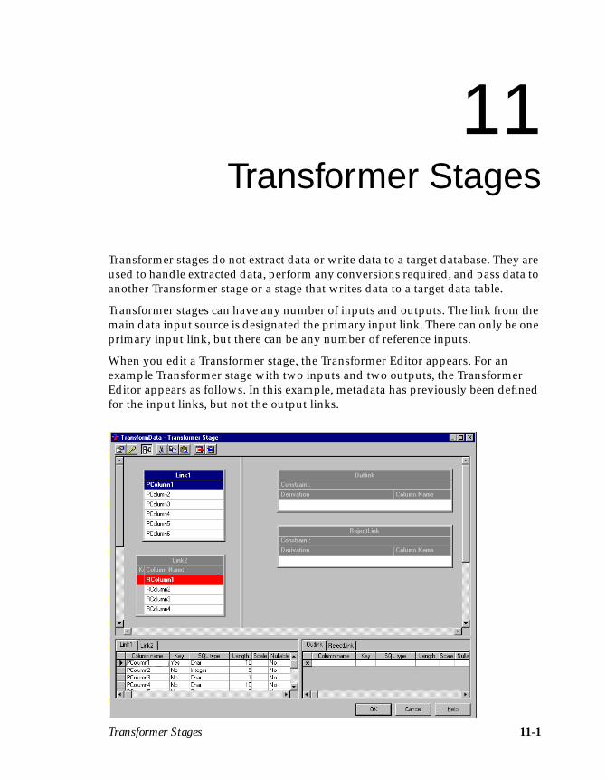
Transformer Stages 11-1
11Transformer Stages
Transformer stages do not extract data or write data to a target database. They areused to handle extracted data, perform any conversions required, and pass data toanother Transformer stage or a stage that writes data to a target data table.
Transformer stages can have any number of inputs and outputs. The link from themain data input source is designated the primary input link. There can only be oneprimary input link, but there can be any number of reference inputs.
When you edit a Transformer stage, the Transformer Editor appears. For anexample Transformer stage with two inputs and two outputs, the TransformerEditor appears as follows. In this example, metadata has previously been definedfor the input links, but not the output links.
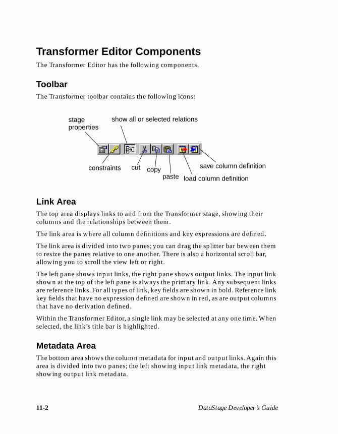
11-2 DataStage Developer’s Guide
Transformer Editor ComponentsThe Transformer Editor has the following components.
ToolbarThe Transformer toolbar contains the following icons:
Link AreaThe top area displays links to and from the Transformer stage, showing theircolumns and the relationships between them.
The link area is where all column definitions and key expressions are defined.
The link area is divided into two panes; you can drag the splitter bar beween themto resize the panes relative to one another. There is also a horizontal scroll bar,allowing you to scroll the view left or right.
The left pane shows input links, the right pane shows output links. The input linkshown at the top of the left pane is always the primary link. Any subsequent linksare reference links. For all types of link, key fields are shown in bold. Reference linkkey fields that have no expression defined are shown in red, as are output columnsthat have no derivation defined.
Within the Transformer Editor, a single link may be selected at any one time. Whenselected, the link’s title bar is highlighted.
Metadata AreaThe bottom area shows the column metadata for input and output links. Again thisarea is divided into two panes; the left showing input link metadata, the rightshowing output link metadata.
stageproperties
show all or selected relations
constraints cut copypaste load column definition
save column definition
Transformer Stages 11-3
The metadata for each link is shown in a grid contained within a tabbed page. Clickthe tab to bring the required link to the front. That link is also selected in the linkarea.
If you select a link in the link area, its metadata page is brought to the frontautomatically.
You can edit the grids to change the column metadata on any of the links. You canalso add and delete metadata.
Shortcut MenusThe Transformer Editor shortcut menus are invoked by right-clicking the links inthe links area.
There are two slightly different menus, depending on whether you right-click aninput link or an output link. The input link menu offers you operations on keyexpressions; the output link menu offers you operations on derivations.
The shortcut menu enables you to:
• Edit, validate, or clear a key expression or derivation.• Append a new column to the selected link.• Find a particular column.• Select all columns on a link.• Insert or delete columns.• Cut, copy, and paste a column or a key expression or a derivation.
If you invoke the menu from a link header, you can:
• Invoke the Properties dialog box to enter a description of the link.
• Invoke the Constraints dialog box to specify a constraint (only available foroutput links).
Right-clicking in the links area background invokes the background shortcutmenu. This menu allows you to invoke the Stage Properties dialog box in order tospecify a before- or after-stage subroutine, or the Constraints dialog box in orderto specify a constraint for the selected output link. This menu also allows you totoggle between viewing link relations for all links, or for the selected link only.
Right-clicking in the metadata area of the Transformer Editor invokes the standardgrid editing shortcut menus.
11-4 DataStage Developer’s Guide
Transformer Stage Basic ConceptsWhen you first edit a Transformer stage, it is likely that you will have alreadydefined what data is input to the stage on the input links. You will use the Trans-former Editor to define the data that will be output by the stage and how it will betransformed. (You can define input data using the Transformer Editor if required.)
This section explains some of the basic concepts of using a Transformer stage.
Input LinksThe main data source is joined to the Transformer stage via the primary link, butthe stage can also have any number of reference input links.
A reference link represents a table lookup. These are used to provide informationthat might affect the way the data is changed, but do not supply the actual data tobe changed.
Reference input columns can be designated as key fields. You can specify keyexpressions that are used to evaluate the key fields. The most common use for thekey expression is to specify an equijoin, which is a link between a primary linkcolumn and a reference link column. For example, if your primary input datacontains names and addresses, and a reference input contains names and phonenumbers, the reference link name column is marked as a key field and the keyexpression refers to the primary link’s name column. During processing, the namein the primary input is looked up in the reference input. If the names match, thereference data is consolidated with the primary data. If the names do not match,i.e., there is no record in the reference input whose key matches the expressiongiven, all the columns specified for the reference input are set to the null value.
Output LinksYou can have any number of output links from your Transformer stage.
You may want to pass some data straight through the Transformer stage unaltered,but it’s likely that you’ll want to transform data from some input columns beforeoutputting it from the Transformer stage.
You can specify such an operation by entering a BASIC expression or by selectinga transform function to apply to the data. DataStage has many built-in transforms,or you can define your own custom transforms that are stored in the Repositoryand can be reused as required.
Transformer Stages 11-5
The source of an output link column is defined in that column’s Derivation cellwithin the Transformer Editor. You can use the Expression Editor to enter expres-sions or transforms in this cell. You can also simply drag an input column to anoutput column’s Derivation cell, to pass the data straight through the Transformerstage.
In addition to specifying derivation details for individual output columns, you canalso specify constraints that operate on entire output links. A constraint is a BASICexpression that specifies criteria that data must meet before it can be passed to theoutput link. You can also specify a reject link, which is an output link that carriesall the data not output on other links, that is, columns that have not met the criteria.
Each output link is processed in turn. If the constraint expression evaluates toTRUE for an input row, the data row is output on that link. Conversely, if aconstraint expression evaluates to FALSE for an input row, the data row is notoutput on that link.
Constraint expressions on different links are independent. If you have more thanone output link, an input row may result in a data row being output from some,none, or all of the output links.
For example, if you consider the data that comes from a paint shop, it could includeinformation about any number of different colors. If you want to separate thecolors into different files, you would set up different constraints. You could outputthe information about green and blue paint on LinkA, red and yellow paint onLinkB, and black paint on LinkC.
When an input row contains information about yellow paint, the LinkA constraintexpression evaluates to FALSE and the row is not output on LinkA. However, theinput data does satisfy the constraint criterion for LinkB and the rows are outputon LinkB.
If the input data contains information about white paint, this does not satisfy anyconstraint and the data row is not output on Links A, B or C, but will be output onthe reject link. The reject link is used to route data to a table or file that is a “catch-all” for rows that are not output on any other link. The table or file containing theserejects is represented by another stage in the job design.
Before-stage and After-stage RoutinesBecause the Transformer stage is an active stage type, you can specify routines tobe executed before or after the stage has processed the data. For example, youmight use a before-stage routine to prepare the data before processing starts. Youmight use an after-stage routine to send an electronic message when the stage hasfinished.
11-6 DataStage Developer’s Guide
Editing Transformer StagesThe Transformer Editor enables you to perform the following operations on aTransformer stage:
• Create new columns on a link• Delete columns from within a link• Move columns within a link• Edit column metadata• Define output column derivations• Define input column key expressions• Specify before- and after-stage subroutines• Define link constraints and handle rejects
Using Drag and DropMany of the Transformer stage edits can be made simpler by using the TransformerEditor’s drag and drop functionality. You can drag columns from any link to anyother link. Common uses are:
• Copying input columns to output links• Moving columns within a link• Copying derivations in output links• Copying key expressions in input links
To use drag and drop:
1. Click the source cell to select it.
2. Click the selected cell again and, without releasing the mouse button, dragthe mouse pointer to the desired location within the target link. An insertpoint appears on the target link to indicate where the new cell will go.
3. Release the mouse button to drop the selected cell.
You can drag and drop multiple columns, key expressions, or derivations. Use thestandard Explorer keys when selecting the source column cells, then proceed as fora single cell.
You can add a column to the end of an existing derivation or key expression byholding down the Ctrl key as you drag the column.
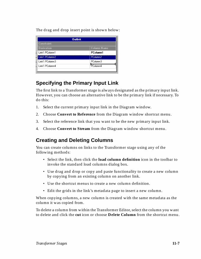
Transformer Stages 11-7
The drag and drop insert point is shown below:
Specifying the Primary Input LinkThe first link to a Transformer stage is always designated as the primary input link.However, you can choose an alternative link to be the primary link if necessary. Todo this:
1. Select the current primary input link in the Diagram window.
2. Choose Convert to Reference from the Diagram window shortcut menu.
3. Select the reference link that you want to be the new primary input link.
4. Choose Convert to Stream from the Diagram window shortcut menu.
Creating and Deleting ColumnsYou can create columns on links to the Transformer stage using any of thefollowing methods:
• Select the link, then click the load column definition icon in the toolbar toinvoke the standard load columns dialog box.
• Use drag and drop or copy and paste functionality to create a new columnby copying from an existing column on another link.
• Use the shortcut menus to create a new column definition.
• Edit the grids in the link’s metadata page to insert a new column.
When copying columns, a new column is created with the same metadata as thecolumn it was copied from.
To delete a column from within the Transformer Editor, select the column you wantto delete and click the cut icon or choose Delete Column from the shortcut menu.
11-8 DataStage Developer’s Guide
Moving Columns Within a LinkYou can move columns within a link using either drag and drop or cut and paste.Select the required column, then drag it to its new location, or cut it and paste it inits new location.
Editing Column MetadataYou can edit column metadata from within the grid in the bottom of the Trans-former Editor. Select the page for the link metadata that you want to edit, then usethe standard DataStage edit grid controls.
The metadata shown does not include column derivations or key expressions,since these are edited in the links area.
Defining Output Column DerivationsYou can define the derivation of output columns from within the TransformerEditor in three ways:
• If you require an output column to be directly derived from an inputcolumn, with no transformations performed, then you can use drag anddrop or copy and paste to copy an input column to an output link. Theoutput columns will have the same names as the input columns fromwhich they were derived.
• You may need one output link column derivation to be the same as anotheroutput link column derivation. In this case you can use drag and drop orcopy and paste to copy the derivation cell from one column to another.
• In many cases you will need to transform data before deriving an outputcolumn from it. For these purposes you can use the Expression Editor. Todisplay the Expression Editor, double-click on the required output linkcolumn Derivation cell. (You can also invoke the Expression Editor usingthe shortcut menu or the shortcut keys.)
If a derivation is displayed in red it means that the Transformer Editor considers itincorrect. (In some cases this may simply mean that the derivation does not meetthe strict usage pattern rules of the DataStage engine, but will actually functioncorrectly.)
Once an output link column has a derivation defined that contains any input linkcolumns, then a relationship line is drawn between the input column and theoutput column, as shown in the following example. This is a simple example; therecan be multiple relationship lines either in or out of columns. You can choosewhether to view the relationships for all links, or just the relationships for theselected links, using the icon in the toolbar.

Transformer Stages 11-9
Defining Input Column Key ExpressionsYou can define key expressions for key fields of reference inputs. This is similar todefining derivations for output columns.
In most cases a key expression will be an equijoin from a primary input linkcolumn. You can specify an equijoin in two ways:
• Use drag and drop to drag a primary input link column to the appropriatekey expression cell.
• Use copy and paste to copy a primary input link column and paste it on theappropriate key expression cell.
A relationship link is drawn between the primary input link column and the keyexpression.
You can also use drag and drop or copy and paste to copy an existing key expres-sion to another input column, and you can drag or copy multiple selections.
If you require a more complex expression than an equijoin, then you can double-click the required key expression cell to invoke the Expression Editor.
If a key expression is displayed in red it means that the Transformer Editorconsiders it incorrect. (In some cases this may simply mean that the key expressiondoes not meet the strict usage pattern rules of the DataStage engine, but will actu-ally function correctly.)
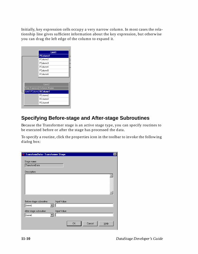
11-10 DataStage Developer’s Guide
Initially, key expression cells occupy a very narrow column. In most cases the rela-tionship line gives sufficient information about the key expression, but otherwiseyou can drag the left edge of the column to expand it.
Specifying Before-stage and After-stage SubroutinesBecause the Transformer stage is an active stage type, you can specify routines tobe executed before or after the stage has processed the data.
To specify a routine, click the properties icon in the toolbar to invoke the followingdialog box:

Transformer Stages 11-11
The dialog box contains the following fields:
• Before-stage subroutine and Input Value. Contain the name (and value) ofa subroutine that is executed before the stage starts to process any data.
• After-stage subroutine and Input Value. Contain the name (and value) ofa subroutine that is executed after the stage has processed the data.
Choose a routine from the drop-down list box. This list box contains all the builtroutines defined as a Before/After Subroutine under the Routines branch in theRepository. Enter an appropriate value for the routine’s input argument in theInput Value field.
If you choose a routine that is defined in the Repository, but which was edited butnot compiled, a warning message reminds you to compile the routine when youclose the Transformer stage dialog box.
If you installed or imported a job, the Before-stage subroutine or After-stagesubroutine field may reference a routine that does not exist on your system. In thiscase, a warning message appears when you close the dialog box. You must installor import the “missing” routine or choose an alternative one to use.
If you edit a job created using Release 1 of DataStage, the Before-stage subroutineor After-stage subroutine field may contain the name of a routine created atRelease 1. When DataStage is upgraded, these routines are identified and automat-ically renamed. For example, if you used a before-stage subroutine calledBeforeSubr, this appears as BeforeSubr\<Rev1> in the Before-stage subroutinefield. You can continue to use these routines. However, because you could notspecify input values for routines at Release 1 of DataStage, the Input Value fieldgrays out when you use one of these “old” routines.
Defining Constraints and Handling RejectsYou can define limits for output data by specifying a constraint. Constraints areBASIC expressions and you can specify a constraint for each output link from aTransformer stage. You can also specify that a particular link is to act as a rejectlink. Reject links output rows that have not been written on any other output linksfrom the transformer stage.
To define a constraint or specify a reject link, do one of the following:
• Select an output link and click the constraints icon.• Double-click the output link’s constraint entry field.• Choose Constraints from the background or header shortcut menus.
A dialog box appears which allows you either to define constraints for any of theTransformer output links or to define a link as a reject link.
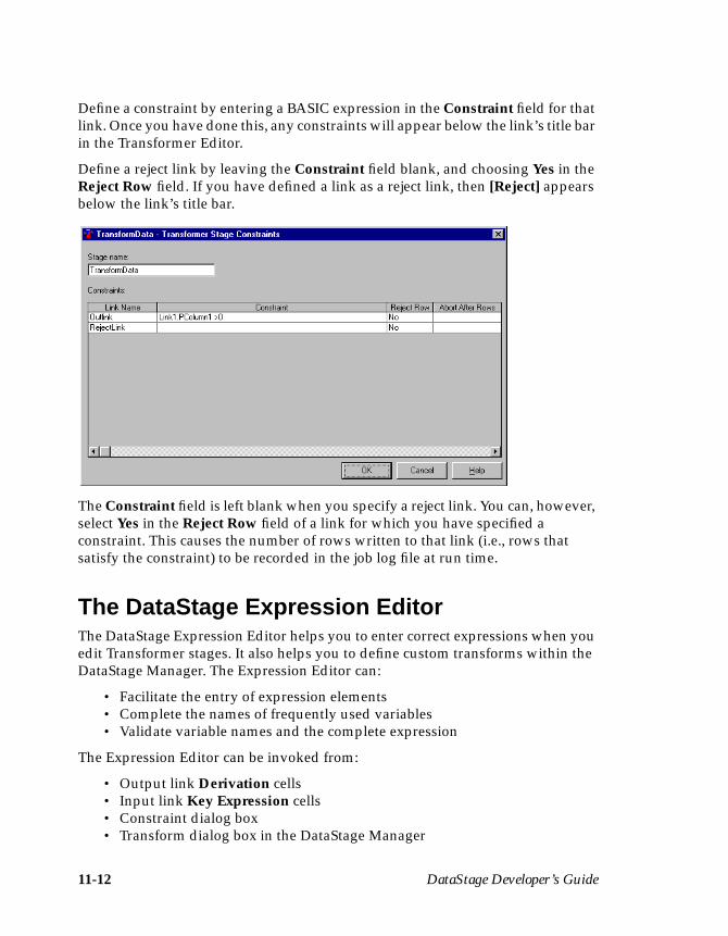
11-12 DataStage Developer’s Guide
Define a constraint by entering a BASIC expression in the Constraint field for thatlink. Once you have done this, any constraints will appear below the link’s title barin the Transformer Editor.
Define a reject link by leaving the Constraint field blank, and choosing Yes in theReject Row field. If you have defined a link as a reject link, then [Reject] appearsbelow the link’s title bar.
The Constraint field is left blank when you specify a reject link. You can, however,select Yes in the Reject Row field of a link for which you have specified aconstraint. This causes the number of rows written to that link (i.e., rows thatsatisfy the constraint) to be recorded in the job log file at run time.
The DataStage Expression EditorThe DataStage Expression Editor helps you to enter correct expressions when youedit Transformer stages. It also helps you to define custom transforms within theDataStage Manager. The Expression Editor can:
• Facilitate the entry of expression elements• Complete the names of frequently used variables• Validate variable names and the complete expression
The Expression Editor can be invoked from:
• Output link Derivation cells• Input link Key Expression cells• Constraint dialog box• Transform dialog box in the DataStage Manager

Transformer Stages 11-13
Entering ExpressionsWhenever the insertion point is in an expression box, you can use the ExpressionEditor to suggest the next element in your expression. Do this by right-clicking thebox, or by clicking the Suggest button to the right of the box. This invokes theSuggest Operand or Suggest Operator menu. Which menu appears depends oncontext, i.e., whether you should be entering an operand or an operator as the nextexpression element.
You will be offered a different selection on the Suggest Operand menu dependingon whether you are defining key expressions, derivations and constraints, or acustom transform. The Suggest Operator menu is always the same.
Completing Variable NamesThe Expression Editor stores variable names. When you enter a variable name youhave used before, you can type the first few characters, then press F5. The Expres-sion Editor completes the variable name for you.
If you enter the name of an input link followed by a period, for example,DailySales. , the Expression Editor displays a list of the column names of thatlink. If you continue typing, the list selection changes to match what you type. Youcan also select a column name using the mouse. Enter a selected column name intothe expression by pressing Tab or Enter. Press Esc to dismiss the list withoutselecting a column name.
Suggest Operand
Transformer Stage
Suggest Operand
Defining CustomMenu Menu
Transforms
Suggest Operator Menu
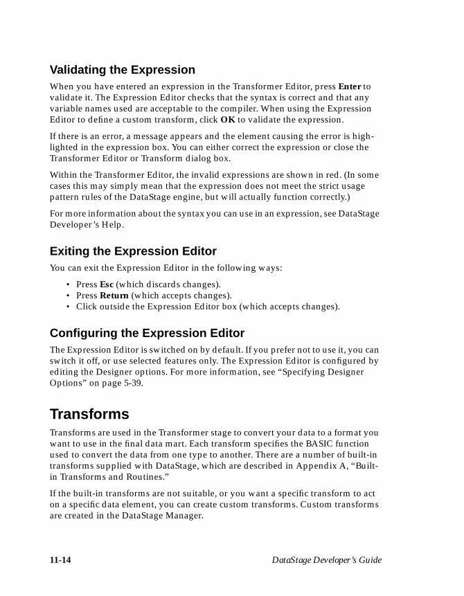
11-14 DataStage Developer’s Guide
Validating the ExpressionWhen you have entered an expression in the Transformer Editor, press Enter tovalidate it. The Expression Editor checks that the syntax is correct and that anyvariable names used are acceptable to the compiler. When using the ExpressionEditor to define a custom transform, click OK to validate the expression.
If there is an error, a message appears and the element causing the error is high-lighted in the expression box. You can either correct the expression or close theTransformer Editor or Transform dialog box.
Within the Transformer Editor, the invalid expressions are shown in red. (In somecases this may simply mean that the expression does not meet the strict usagepattern rules of the DataStage engine, but will actually function correctly.)
For more information about the syntax you can use in an expression, see DataStageDeveloper’s Help.
Exiting the Expression EditorYou can exit the Expression Editor in the following ways:
• Press Esc (which discards changes).• Press Return (which accepts changes).• Click outside the Expression Editor box (which accepts changes).
Configuring the Expression EditorThe Expression Editor is switched on by default. If you prefer not to use it, you canswitch it off, or use selected features only. The Expression Editor is configured byediting the Designer options. For more information, see “Specifying DesignerOptions” on page 5-39.
TransformsTransforms are used in the Transformer stage to convert your data to a format youwant to use in the final data mart. Each transform specifies the BASIC functionused to convert the data from one type to another. There are a number of built-intransforms supplied with DataStage, which are described in Appendix A, “Built-in Transforms and Routines.”
If the built-in transforms are not suitable, or you want a specific transform to acton a specific data element, you can create custom transforms. Custom transformsare created in the DataStage Manager.
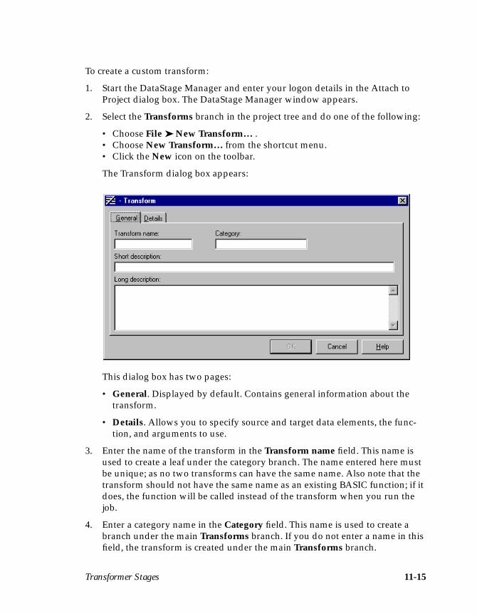
Transformer Stages 11-15
To create a custom transform:
1. Start the DataStage Manager and enter your logon details in the Attach toProject dialog box. The DataStage Manager window appears.
2. Select the Transforms branch in the project tree and do one of the following:
• Choose File ➤ New Transform… .• Choose New Transform… from the shortcut menu.• Click the New icon on the toolbar.
The Transform dialog box appears:
This dialog box has two pages:
• General. Displayed by default. Contains general information about thetransform.
• Details. Allows you to specify source and target data elements, the func-tion, and arguments to use.
3. Enter the name of the transform in the Transform name field. This name isused to create a leaf under the category branch. The name entered here mustbe unique; as no two transforms can have the same name. Also note that thetransform should not have the same name as an existing BASIC function; if itdoes, the function will be called instead of the transform when you run thejob.
4. Enter a category name in the Category field. This name is used to create abranch under the main Transforms branch. If you do not enter a name in thisfield, the transform is created under the main Transforms branch.
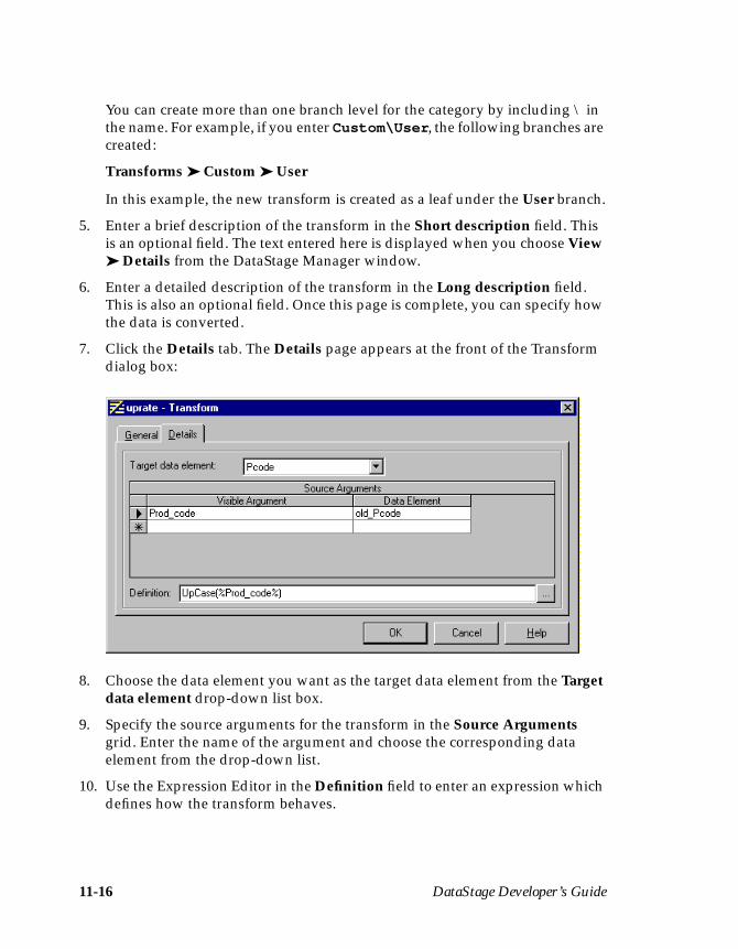
11-16 DataStage Developer’s Guide
You can create more than one branch level for the category by including \ inthe name. For example, if you enter Custom\User , the following branches arecreated:
Transforms ➤ Custom ➤ User
In this example, the new transform is created as a leaf under the User branch.
5. Enter a brief description of the transform in the Short description field. Thisis an optional field. The text entered here is displayed when you choose View➤ Details from the DataStage Manager window.
6. Enter a detailed description of the transform in the Long description field.This is also an optional field. Once this page is complete, you can specify howthe data is converted.
7. Click the Details tab. The Details page appears at the front of the Transformdialog box:
8. Choose the data element you want as the target data element from the Targetdata element drop-down list box.
9. Specify the source arguments for the transform in the Source Argumentsgrid. Enter the name of the argument and choose the corresponding dataelement from the drop-down list.
10. Use the Expression Editor in the Definition field to enter an expression whichdefines how the transform behaves.
Transformer Stages 11-17
11. Click OK to save the transform and close the Transform dialog box. The newtransform appears in the project tree under the specified branch.
You can then use the new transform from within the Transformer Editor.

11-18 DataStage Developer’s Guide

Aggregator Stages 12-1
12Aggregator Stages
Aggregator stages classify data rows from a single input link into groups andcompute totals or other aggregate functions for each group. The summed totals foreach group are output from the stage via an output link.
If you want to aggregate the input data in a number of different ways, you canhave several output links, each specifying a different set of properties to definehow the input data is grouped and summarized.
When you edit an Aggregator stage, the Aggregator Stage dialog box appears:
12-2 DataStage Developer’s Guide
This dialog box has three pages:
• Stage. Displays the name of the stage you are editing. This page has aGeneral page which contains an optional description of the stage andnames of before- and after-stage routines. For more details about theseroutines, see “Before-stage and After-stage Subroutines” on page 12-2.
Note: You cannot change the name of the stage from this window. Fordetails on how to change stage names, see “Renaming Stages” onpage 5-14.
• Inputs. Specifies the column definitions for the data input link.
• Outputs. Specifies the column definitions for the data output link.
Click OK to close this dialog box. Changes are saved when you save the job.
Before-stage and After-stage SubroutinesThe General page on the Stage page contains optional fields that allow you todefine routines to use which are executed before or after the stage has processedthe data.
• Before-stage subroutine and Input Value. Contain the name (and value) ofa subroutine that is executed before the stage starts to process any data. Forexample, you can specify a routine that prepares the data before processingstarts.
• After-stage subroutine and Input Value. Contain the name (and value) ofa subroutine that is executed after the stage has processed the data. Forexample, you can specify a routine that sends an electronic message whenthe stage has finished.
Choose a routine from the drop-down list box. This list box contains all theroutines defined as a Before/After Subroutine under the Routines branch in theRepository. Enter an appropriate value for the routine’s input argument in theInput Value field.
If you choose a routine that is defined in the Repository, but which was edited butnot compiled, a warning message reminds you to compile the routine when youclose the Aggregator Stage dialog box.
If you installed or imported a job, the Before-stage subroutine or After-stagesubroutine field may reference a routine that does not exist on your system. In thiscase, a warning message appears when you close the Aggregator Stage dialog box.You must install or import the “missing” routine or choose an alternative one touse.
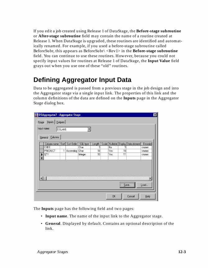
Aggregator Stages 12-3
If you edit a job created using Release 1 of DataStage, the Before-stage subroutineor After-stage subroutine field may contain the name of a routine created atRelease 1. When DataStage is upgraded, these routines are identified and automat-ically renamed. For example, if you used a before-stage subroutine calledBeforeSubr, this appears as BeforeSubr\<Rev1> in the Before-stage subroutinefield. You can continue to use these routines. However, because you could notspecify input values for routines at Release 1 of DataStage, the Input Value fieldgrays out when you use one of these “old” routines.
Defining Aggregator Input DataData to be aggregated is passed from a previous stage in the job design and intothe Aggregator stage via a single input link. The properties of this link and thecolumn definitions of the data are defined on the Inputs page in the AggregatorStage dialog box.
The Inputs page has the following field and two pages:
• Input name. The name of the input link to the Aggregator stage.
• General. Displayed by default. Contains an optional description of thelink.
12-4 DataStage Developer’s Guide
• Columns. Contains a grid displaying the column definitions for the databeing written to the stage, and an optional sort order.
– Column name. The name of the column.
– Sort. Displays the sort key position of the column, if sorting is enabled.For more information, see “Defining the Input Column Sort Order” onpage 12-4.
– Sort Order. Specifies the sort order. This field is blank by default, that is,there is no sort order. Choose Ascending for ascending order,Descending for descending order, or Ignore if you do not want the orderto be checked.
– SQL type. The SQL data type.
– Length. The data precision. This is the length for CHAR data and themaximum length for VARCHAR data.
– Scale. The data scale factor.
– Nullable. Specifies whether the column can contain null values.
– Display. The maximum number of characters required to display thecolumn data.
– Data element. The type of data in the column.
– Description. A text description of the column.
For a description of how to enter and edit column definitions, see “Speci-fying Column Definitions” on page 5-18.
Defining the Input Column Sort OrderWhen the Aggregator stage collates input data for aggregating, it is stored inmemory. If one or more group columns in the input data are sorted, this can greatlyimprove the way in which the Aggregator stage handles the data.
Sorted input data can be output from an ODBC or UniVerse stage (using anORDER BY clause in the SQL statement) or a Sequential File stage.
To use sorted input data, you can use the additional column properties in the InputColumn dialog box.
Enter a number in the Sort column specifying the position that column has in thesort key. For example, if the input data was sorted on a date then on a product code,the sort key position for the date column would 1 and the sort key position for theproduct code column would be 2. A value of 1 always indicates the most signifi-cant key. If you do not specify a value in this field, the column is added to the end
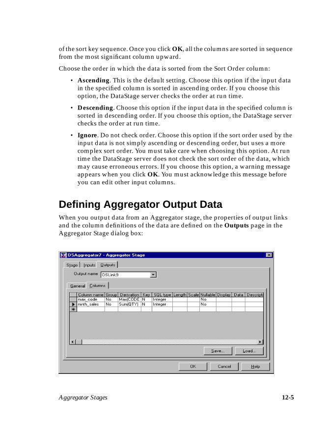
Aggregator Stages 12-5
of the sort key sequence. Once you click OK, all the columns are sorted in sequencefrom the most significant column upward.
Choose the order in which the data is sorted from the Sort Order column:
• Ascending. This is the default setting. Choose this option if the input datain the specified column is sorted in ascending order. If you choose thisoption, the DataStage server checks the order at run time.
• Descending. Choose this option if the input data in the specified column issorted in descending order. If you choose this option, the DataStage serverchecks the order at run time.
• Ignore. Do not check order. Choose this option if the sort order used by theinput data is not simply ascending or descending order, but uses a morecomplex sort order. You must take care when choosing this option. At runtime the DataStage server does not check the sort order of the data, whichmay cause erroneous errors. If you choose this option, a warning messageappears when you click OK. You must acknowledge this message beforeyou can edit other input columns.
Defining Aggregator Output DataWhen you output data from an Aggregator stage, the properties of output linksand the column definitions of the data are defined on the Outputs page in theAggregator Stage dialog box:
12-6 DataStage Developer’s Guide
The Outputs page has the following field and two pages:
• Output name. The name of the output link. Choose the link to edit from theOutput name drop-down list box. This list box displays all the output linksfrom the stage.
• General. Displayed by default. Contains an optional description of thelink.
• Columns. Contains a grid displaying the column definitions for the databeing output from the stage. The grid has the following columns:
– Column name. The name of the column.
– Group. Specifies whether to group by the data in the column. Choose Yesto group by the column.
– Derivation. Contains an expression specifying how the data is aggre-gated. This is a complex cell, requiring more than one piece ofinformation. Double-clicking on the cell invokes the Derivation dialogbox. For more information, see “Aggregating Data” on page 12-7.
– Key. Indicates whether the column is part of the primary key.
– SQL type. The SQL data type.
– Length. The data precision. This is the length for CHAR data and themaximum length for VARCHAR data.
– Scale. The data scale factor.
– Nullable. Specifies whether the column can contain null values.
– Display. The maximum number of characters required to display thecolumn data.
– Data element. The type of data in the column.
– Description. A text description of the column.
For a description of how to enter and edit column definitions, see “Speci-fying Column Definitions” on page 5-18.
Aggregator Stages 12-7
Aggregating DataThe data sources you are extracting data from can contain many thousands of rowsof data. For example, the data in a sales database can contain information abouteach transaction or sale. You could pass all this data into your data warehouse.However, this would mean you would have to search through large volumes ofdata in the data warehouse before you get the results you need.
If you only want summary information, for example, the total of product A soldsince 01/01/96, you can aggregate your data and only pass the summed total tothe data warehouse. This reduces the amount of data you store in the data ware-house, speeds up the time taken to find the data you want, and ensures the datawarehouse stores data in a format you need.
The Aggregator stage allows you to group by or summarize any columns on anyof the output links.
Note: Every column output from an Aggregator stage must be either grouped byor summarized.
A group of input data is a set of input rows that share the same values for all thegrouped by columns. For example, if your sales database contained informationabout three different products A, B, and C, you could group by the Productcolumn. All the information about product A would be grouped together, aswould all the information for products B and C.
By summarizing data, you can perform basic calculations on the values in a partic-ular column. The actions you can perform depend on the SQL data type of theselected column.
For numeric SQL data types you can perform the following actions:
• Minimum. Returns the lowest value in the column.
• Maximum. Returns the highest value in the column.
• Count. Counts the number of values in the column.
• Sum. Totals the values in the column.
• Average. Averages the values in the column.
• Standard deviation. Returns the standard deviation for the values in thecolumn.
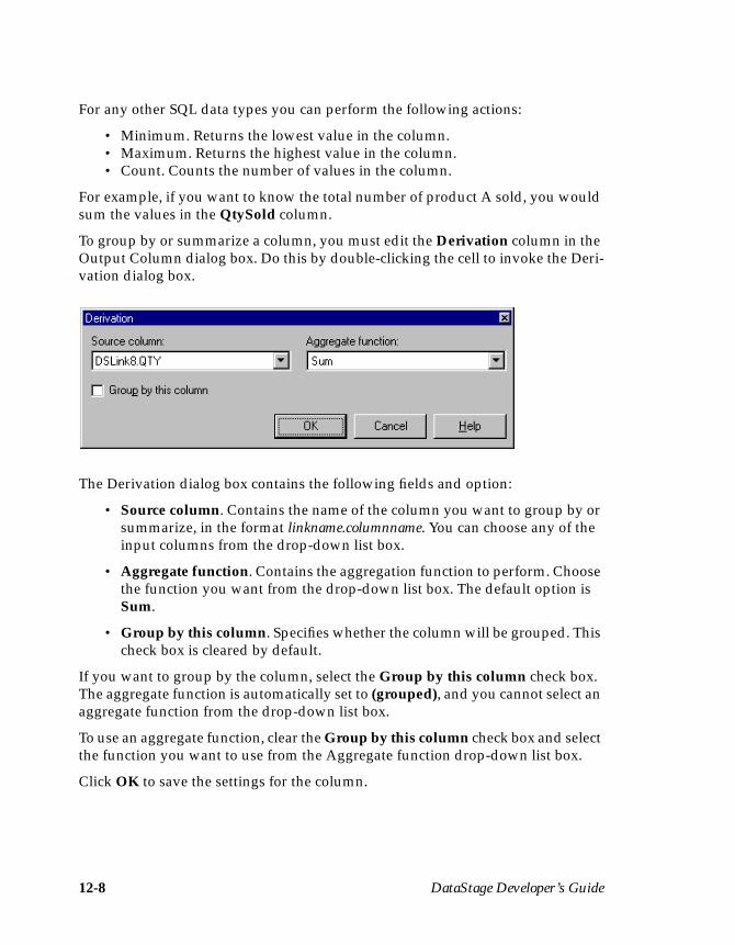
12-8 DataStage Developer’s Guide
For any other SQL data types you can perform the following actions:
• Minimum. Returns the lowest value in the column.• Maximum. Returns the highest value in the column.• Count. Counts the number of values in the column.
For example, if you want to know the total number of product A sold, you wouldsum the values in the QtySold column.
To group by or summarize a column, you must edit the Derivation column in theOutput Column dialog box. Do this by double-clicking the cell to invoke the Deri-vation dialog box.
The Derivation dialog box contains the following fields and option:
• Source column. Contains the name of the column you want to group by orsummarize, in the format linkname.columnname. You can choose any of theinput columns from the drop-down list box.
• Aggregate function. Contains the aggregation function to perform. Choosethe function you want from the drop-down list box. The default option isSum.
• Group by this column. Specifies whether the column will be grouped. Thischeck box is cleared by default.
If you want to group by the column, select the Group by this column check box.The aggregate function is automatically set to (grouped), and you cannot select anaggregate function from the drop-down list box.
To use an aggregate function, clear the Group by this column check box and selectthe function you want to use from the Aggregate function drop-down list box.
Click OK to save the settings for the column.
Aggregator Stages 12-9
The AGGREGATOR Plug-inAt DataStage Release 1.0, aggregation was performed using the AGGREGATORPlug-in. This Plug-in is no longer available and is superseded by the built-inAggregator stage. During installation, any jobs that used the AGGREGATOR Plug-in are converted to use the built-in Aggregator stage instead. You do not need torecompile your job to use the Aggregator stage.

12-10 DataStage Developer’s Guide
Plug-ins and Plug-in Stages 13-1
13Plug-ins and Plug-in
Stages
This chapter describes how to create a Plug-in and use a Plug-in stage in your jobdesign.
You may find that the built-in stage types do not meet all your requirements fordata extraction and transformation. If this is the case, you need to write a Plug-in,which can then be used in a Plug-in stage in your job design.
Plug-insPlug-ins are written to perform specific tasks that the built-in stages do notsupport, for example:
• Custom aggregations• Control of external devices (for example, tape drives)• Access to external programs
Two Plug-ins are automatically installed with DataStage:
• BCPLoad. The BCPLoad Plug-in bulk loads data into a single table in aMicrosoft SQL Server (Release 6 or 6.5) or Sybase (System 10 or 11) data-base. For more information about this Plug-in, see Chapter 14, “BCPLoadStages.”
• Orabulk. The Orabulk Plug-in generates control and data files for bulkloading into a single table on an Oracle target database. The files are suit-able for loading into the target database using the Oracle command sqlldr.For more information about this Plug-in, see Chapter 15, “Orabulk Stages.”
Other Plug-ins are supplied with DataStage, but must be explicitly installed.
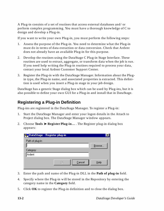
13-2 DataStage Developer’s Guide
A Plug-in consists of a set of routines that access external databases and/orperform complex programming. You must have a thorough knowledge of C todesign and develop a Plug-in.
If you want to write your own Plug-in, you must perform the following steps:
1. Assess the purpose of the Plug-in. You need to determine what the Plug-inmust do in terms of data extraction or data conversion. Check that Ardentdoes not already have an available Plug-in for this purpose.
2. Develop the routines using the DataStage C Plug-in Stage Interface. Theseroutines are used to extract, aggregate, or transform data when the job is run.If you need help writing the Plug-in routines required to process your data,contact your local Ardent Customer Support Center.
3. Register the Plug-in with the DataStage Manager. Information about the Plug-in type, the Plug-in name, and associated properties is extracted. This defini-tion is used when you insert a Plug-in stage in your job design.
DataStage has a generic Stage dialog box which can be used by Plug-ins, but it isalso possible to define your own GUI for a Plug-in and install that in DataStage.
Registering a Plug-in DefinitionPlug-ins are registered in the DataStage Manager. To register a Plug-in:
1. Start the DataStage Manager and enter your logon details in the Attach toProject dialog box. The DataStage Manager window appears.
2. Choose Tools ➤ Register Plug-in… . The Register plug-in dialog boxappears:
3. Enter the path and name of the Plug-in DLL in the Path of plug-in field.
4. Specify where the Plug-in will be stored in the Repository by entering thecategory name in the Category field.
5. Click OK to register the Plug-in definition and to close the dialog box.

Plug-ins and Plug-in Stages 13-3
Once the Plug-in has been registered with the Manager, you can view its details inthe Stage Type dialog box. To do this, click the Plug-in icon in the Manager displayarea and do one of the following:
• Choose File ➤ Properties… .• Choose Properties… from the shortcut menu.• Double-click the Plug-in in the display area.• Click the Properties icon on the toolbar.
Note that the Plug-in definition is read-only; you cannot change any of the details.The only exception to this is a Plug-in that you added under an earlier version ofDataStage.
This dialog box has five pages:
• General. Contains the name and type of the Plug-in and optional short andlong descriptions. This page also contains the name and path of the Plug-inDLL, and specifies whether the Plug-in supports metadata import or databrowsing.
• Links. Contains information about what type of links can connect to thePlug-in stage as inputs and the maximum and minimum number of linksallowed.
• Creator. Displays information about the creator and the version of thePlug-in.
13-4 DataStage Developer’s Guide
• Properties. Specifies properties for the stage and the input and outputlinks.
• Dependencies. Specifies the dependent DLLs.
Removing a Registered Plug-inTo remove a Plug-in that you have previously registered:
1. Select the Plug-in in the DataStage Manager display area.
2. Choose Tools ➤ Unregister Plug-in.The Plug-in is removed.
Installing a Plug-inIf a third party supplies you with a Plug-in, you need to install this into yourRepository. Plug-ins are supplied in a package. For details on how to install apackage, see DataStage Administrator’s Guide.
Packaging a Plug-inIf you have written a Plug-in that you want to distribute to users on otherDataStage systems, you need to package it. For details on how to package a Plug-in for deployment, see Chapter 19, “Importing, Exporting, and Packaging Jobs.”
Using a Plug-inYou can use a Plug-in by inserting a Plug-in stage in your job design. Plug-in stagesare used the same way as built-in stages. However, when you insert a Plug-instage, you are prompted to choose the Plug-in to use. For details of how to includea Plug-in stage in your job design, see “Adding Plug-in Stages” on page 5-13.
The Plug-in you choose determines the function and properties of the Plug-instage. When you have chosen a Plug-in, you can edit the stage to define the dataflowing into, through, or from it.
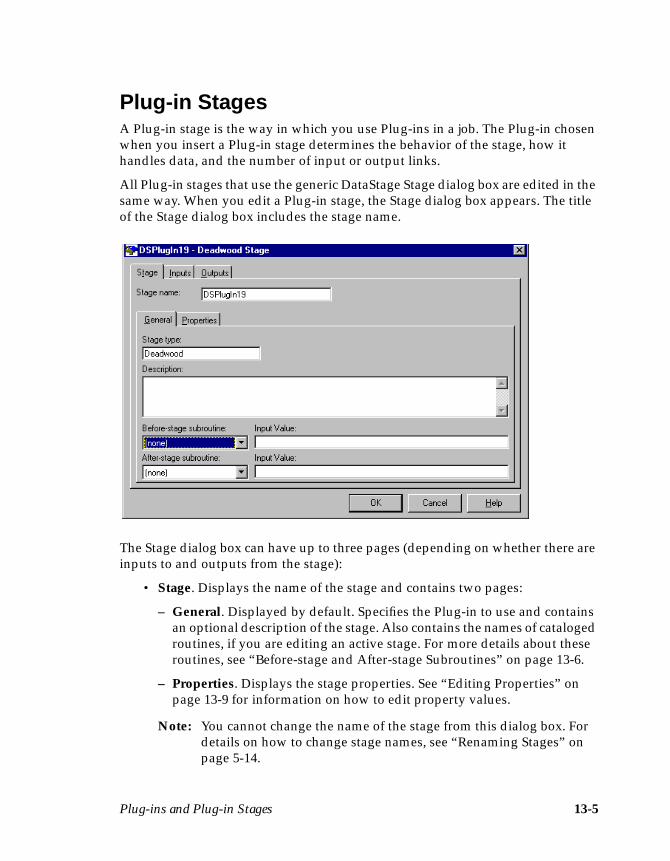
Plug-ins and Plug-in Stages 13-5
Plug-in StagesA Plug-in stage is the way in which you use Plug-ins in a job. The Plug-in chosenwhen you insert a Plug-in stage determines the behavior of the stage, how ithandles data, and the number of input or output links.
All Plug-in stages that use the generic DataStage Stage dialog box are edited in thesame way. When you edit a Plug-in stage, the Stage dialog box appears. The titleof the Stage dialog box includes the stage name.
The Stage dialog box can have up to three pages (depending on whether there areinputs to and outputs from the stage):
• Stage. Displays the name of the stage and contains two pages:
– General. Displayed by default. Specifies the Plug-in to use and containsan optional description of the stage. Also contains the names of catalogedroutines, if you are editing an active stage. For more details about theseroutines, see “Before-stage and After-stage Subroutines” on page 13-6.
– Properties. Displays the stage properties. See “Editing Properties” onpage 13-9 for information on how to edit property values.
Note: You cannot change the name of the stage from this dialog box. Fordetails on how to change stage names, see “Renaming Stages” onpage 5-14.
13-6 DataStage Developer’s Guide
• Inputs. Contains information about the column definitions for each datainput link and specifies the input link properties. For more information, see“Defining Plug-in Input Data” on page 13-7.
• Outputs. Contains information about the column definitions for each dataoutput link and specifies the output link properties. For more information,see “Defining Plug-in Output Data” on page 13-8.
Before-stage and After-stage SubroutinesIf you are editing an active type of Plug-in stage, the General page on the Stagepage contains additional fields. These optional fields allow you to define routinesto use which are executed before or after the stage has processed the data:
• Before-stage subroutine and Input Value. Contain the name (and value) ofa subroutine that is executed before the stage starts to process any data. Forexample, you can specify a routine that prepares the data before processingstarts.
• After-stage subroutine and Input Value. Contain the name (and value) ofa subroutine that is executed after the stage has processed the data. Forexample, you can specify a routine that sends an electronic message whenthe stage has finished.
Choose a routine from the drop-down list box. This list box contains all the builtroutines defined as a Before/After Subroutine under the Routines branch in theRepository. Enter an appropriate value for the routine’s input argument in theInput Value field.
If you choose a routine that is defined in the Repository, but which was edited butnot compiled, a warning message reminds you to compile the routine when youclose the Stage dialog box.
If you installed or imported a job, the Before-stage subroutine or After-stagesubroutine field may reference a routine that does not exist on your system. In thiscase, a warning message appears when you close the Stage dialog box. You mustinstall or import the “missing” routine or choose an alternative one to use.
If you edit a job created using Release 1 of DataStage, the Before-stage subroutineor After-stage subroutine field may contain the name of a routine created atRelease 1. When DataStage is upgraded, these routines are identified and automat-ically renamed. For example, if you used a before-stage subroutine calledBeforeSubr, this appears as BeforeSubr\<Rev1> in the Before-stage subroutinefield. You can continue to use these routines. However, because you could notspecify input values for routines at Release 1 of DataStage, the Input Value fieldgrays out when you use one of these “old” routines.
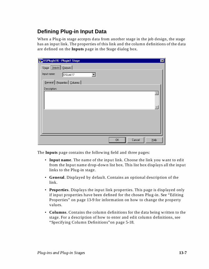
Plug-ins and Plug-in Stages 13-7
Defining Plug-in Input DataWhen a Plug-in stage accepts data from another stage in the job design, the stagehas an input link. The properties of this link and the column definitions of the dataare defined on the Inputs page in the Stage dialog box.
The Inputs page contains the following field and three pages:
• Input name. The name of the input link. Choose the link you want to editfrom the Input name drop-down list box. This list box displays all the inputlinks to the Plug-in stage.
• General. Displayed by default. Contains an optional description of thelink.
• Properties. Displays the input link properties. This page is displayed onlyif input properties have been defined for the chosen Plug-in. See “EditingProperties” on page 13-9 for information on how to change the propertyvalues.
• Columns. Contains the column definitions for the data being written to thestage. For a description of how to enter and edit column definitions, see“Specifying Column Definitions”on page 5-18.
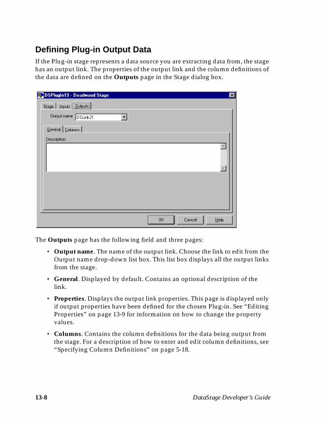
13-8 DataStage Developer’s Guide
Defining Plug-in Output DataIf the Plug-in stage represents a data source you are extracting data from, the stagehas an output link. The properties of the output link and the column definitions ofthe data are defined on the Outputs page in the Stage dialog box.
The Outputs page has the following field and three pages:
• Output name. The name of the output link. Choose the link to edit from theOutput name drop-down list box. This list box displays all the output linksfrom the stage.
• General. Displayed by default. Contains an optional description of thelink.
• Properties. Displays the output link properties. This page is displayed onlyif output properties have been defined for the chosen Plug-in. See “EditingProperties” on page 13-9 for information on how to change the propertyvalues.
• Columns. Contains the column definitions for the data being output fromthe stage. For a description of how to enter and edit column definitions, see“Specifying Column Definitions” on page 5-18.
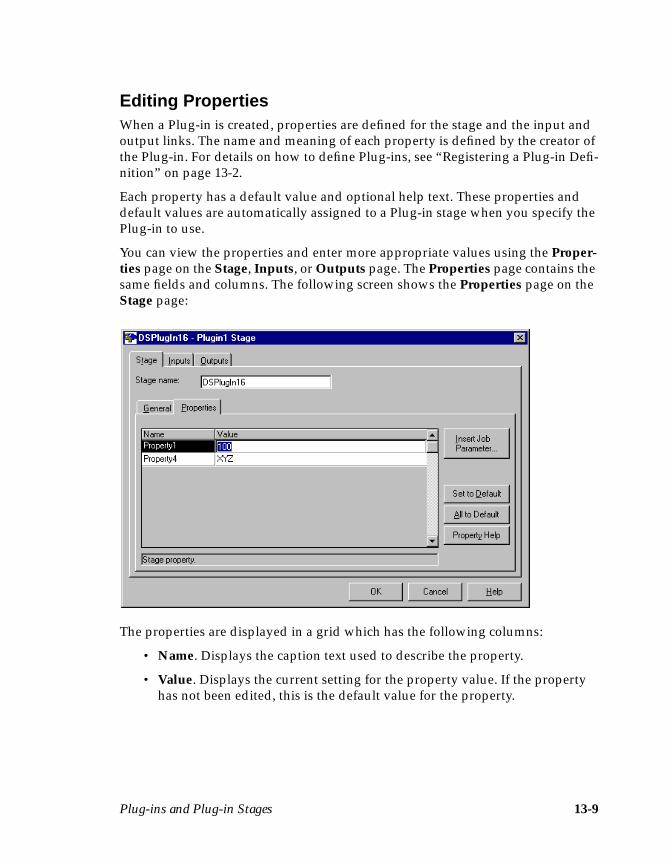
Plug-ins and Plug-in Stages 13-9
Editing PropertiesWhen a Plug-in is created, properties are defined for the stage and the input andoutput links. The name and meaning of each property is defined by the creator ofthe Plug-in. For details on how to define Plug-ins, see “Registering a Plug-in Defi-nition” on page 13-2.
Each property has a default value and optional help text. These properties anddefault values are automatically assigned to a Plug-in stage when you specify thePlug-in to use.
You can view the properties and enter more appropriate values using the Proper-ties page on the Stage, Inputs, or Outputs page. The Properties page contains thesame fields and columns. The following screen shows the Properties page on theStage page:
The properties are displayed in a grid which has the following columns:
• Name. Displays the caption text used to describe the property.
• Value. Displays the current setting for the property value. If the propertyhas not been edited, this is the default value for the property.
13-10 DataStage Developer’s Guide
There are four buttons on this page:
• Insert Job Parameter… . Allows you to insert a job parameter as the valuefor a chosen property. When you click this button, a list appears displayingthe currently defined job parameters. Choose one from the list. If youcannot see the job parameter you want, click (New…) to define a new one.The Job Parameters dialog box appears. For more information about thisdialog box and how to define a job parameter, see “Parameter Types” onpage 5-33. You can also insert a job parameter using the F9 key.
• Set to Default. Sets the value for the chosen property to the default value.This button is only active when you choose a property to edit.
• All to Default. Sets the values for all properties to the default values.
• Property Help. Displays the help text supplied by the creator of the Plug-in, if there is any. This button is only active when you choose a property toedit.
You can edit the value for any properties listed in the grid. Click OK to save thesettings and to close the Stage dialog box.
BCPLoad Stages 14-1
14BCPLoad Stages
The BCPLoad stage is a passive Plug-in stage supplied by Ardent. It bulk loadsdata into a single table in a Microsoft SQL Server (Release 6.0 or 6.5) or Sybase(System 10 or 11) database. The files are loaded into the target database using thebulk copy API.
By default, the BCPLoad stage is configured to bulk load data into a Microsoft SQLServer. You can configure the BCPLoad stage properties to bulk load data into aSybase SQL Server table using the Sybase DBLIB or CTLIB client libraries.
Note: The client libraries used by the BCPLoad stage are not supplied as part ofDataStage. You must obtain these libraries from your DBMS vendor andensure they are installed and configured on your system before attemptingto use the BCPLoad stage.
There is one input link to this stage which provides a sequence of rows to load intothe SQL Server or Sybase database table. The metadata for each input columndetermines how it is loaded. There are no output links from this stage type.
OverviewMicrosoft SQL Server and Sybase have a utility called BCP (Bulk Copy Program).This command line utility copies SQL Server data to or from an operating systemfile in a user-specified format. BCP uses the bulk copy API in the SQL Server clientlibraries.
By using BCP, you can load large volumes of data into a table without recordingeach insert in a log file. You can run BCP manually from a command line usingcommand line options (switches). A format (.fmt) file is created which is used toload the data into the database.

14-2 DataStage Developer’s Guide
The BCPLoad stage uses the same API that BCP does, but loads data directlywithout the need for a format file. The command line switches are set using stageproperties.
Because this version of the BCPLoad stage supports both Microsoft SQL Serverand Sybase, only BCP switches common to both servers have been included asstage properties. The following command line switches are not supported forMicrosoft SQL Server:
• –T, trusted connection• –q, quote identifiers
The following command line switches are not supported for Sybase:
• –I, interface file• –J, the client character set• –q, the data character set
For more information about the BCP switches that can be set, see “Stage Proper-ties” on page 14-4.
The BCPLoad stage does not support the loading of native data files.
Before You StartBefore you can use the BCPLoad stage you must:
• Install and configure the SQL Server or Sybase client software. TheBCPLoad stage uses the BCP API in the DBLIB/CTLIB and NetLIB clientlibraries. You must ensure that these components are installed on theDataStage server which is acting as a client to the SQL Server DBMS. Seethe documentation supplied with your DBMS for more details.
• Use one of the client tools (for example, ISQLW in the case of MicrosoftSQL Server or WISQL32 for Sybase) to ensure that the connectivitybetween the DataStage server and the SQL Server host is operational.
• Create the table in the database on the SQL Server.
• Configure your database to use the fast copy (bulk load) option. By usingthis option, the data is loaded without each insert being recorded in a logfile. If you do not specify this setting, all transactions are logged, slowingdown the rate at which data is loaded. The fast copy option can beswitched on by a stored procedure. For more information about usingstored procedures, see “Using Stored Procedures” on page 14-7.
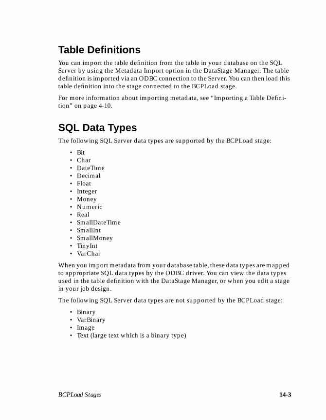
BCPLoad Stages 14-3
Table DefinitionsYou can import the table definition from the table in your database on the SQLServer by using the Metadata Import option in the DataStage Manager. The tabledefinition is imported via an ODBC connection to the Server. You can then load thistable definition into the stage connected to the BCPLoad stage.
For more information about importing metadata, see “Importing a Table Defini-tion” on page 4-10.
SQL Data TypesThe following SQL Server data types are supported by the BCPLoad stage:
• Bit• Char• DateTime• Decimal• Float• Integer• Money• Numeric• Real• SmallDateTime• SmallInt• SmallMoney• TinyInt• VarChar
When you import metadata from your database table, these data types are mappedto appropriate SQL data types by the ODBC driver. You can view the data typesused in the table definition with the DataStage Manager, or when you edit a stagein your job design.
The following SQL Server data types are not supported by the BCPLoad stage:
• Binary• VarBinary• Image• Text (large text which is a binary type)
14-4 DataStage Developer’s Guide
The BCPLoad Plug-in DefinitionWhen the BCPLoad Plug-in is installed, it is stored under Stage Types ➤ Ardentin the Repository. You can view the definition of this Plug-in using the DataStageManager, but you cannot edit it. When you choose to view the definition, the StageType dialog box appears. There are five pages in this dialog box:
• General. Specifies where the BCPLoad Plug-in is installed and contains adescription of the stage.
• Links. Specifies the type of input links which can connect to a BCPLoadstage and gives the maximum and minimum links allowed.
• Creator. Contains information about the creator of this stage.
• Properties. Contains the stage properties for the BCPLoad stage with suit-able default settings. For a list of the properties, see “Stage Properties” onpage 14-4.
• Dependencies. Contains the name of any DLLs used by the Plug-in.
Stage PropertiesThe following properties are defined for the BCPLoad stage. You can view them onthe Properties page in the Stage Type dialog box and change them when you editthe stage instance.
• SQL-Server Name. The name of the SQL Server to connect to. This prop-erty corresponds to the BCP –S switch. This property is optional and has nodefault value. If you leave this property blank in the stage instance, thestage assumes the SQL Server resides on the same machine as theDataStage Server.
• User ID. The logon name of the SQL user. This property corresponds to theBCP –U option. There is no default value for this property. You must enterthe name of the user when you edit the stage instance.
• Password. The password of the SQL user. This property corresponds to theBCP –P option. There is no default value for this property. You must enter apassword when you edit the stage instance.
• Database Name. The name of the database to use on the SQL Server. Thisproperty has no default value. You must enter the name of the databasewhen you edit the stage instance.
• Table Name. The name of the table to load data into. This property has nodefault value. You must enter the name of the table to use when you editthe stage instance.

BCPLoad Stages 14-5
• Before Load Stored Procedure. The name of a stored procedure that isexecuted before the database table is loaded. This property is optional andhas no default value. For more information about using a before-loadstored procedure, see “Using Stored Procedures” on page 14-7.
• After Load Stored Procedure. The name of a stored procedure that isexecuted after the database table is loaded. This property is optional andhas no default value. For more information about using an after-loadstored procedure, see “Using Stored Procedures” on page 14-7.
• Batch Size. The number of rows to include in the BCP batch. This propertycorresponds to the BCP –b option. The default setting for this property is 0,that is, all the data rows are treated in one batch. If an error occurs, all rowsare rolled back.
• Packet Size. The number of bytes per network packet sent to and from theserver. The default value is 4096. When you edit the stage instance, you canenter any number from 512 through 65535.
• Use Source Identity Data. This property corresponds to the BCP /Eswitch. Setting this property tells the SQL Server to use the identity valuesthat are passed to it by the BCPLoad stage, to populate the correspondingidentity column in the SQL Server table.
• Date Format. This property provides a workaround to the problem thatMicrosoft SQL Server has with dates in YMD format. If your target tablehas a date column and your data has dates in YMD format, a conversion isrequired for the date to load successfully. By setting this property to ymd,dates are automatically converted during loading to a format thatMicrosoft SQL Server accepts.
• Client Library. The type of client library to use. The default setting isMSDBLIB (the Microsoft DBLibrary). Other valid settings are SYBDBLIBfor the Sybase DBLibrary and SYBCTLIB for the Sybase CTLibrary.
Using the BCPLoad StageThe BCPLoad Plug-in is preinstalled and can be used immediately. To use thisPlug-in, you must insert a Plug-in stage in your job design:
1. Start the DataStage Designer and open your job design.
2. Click the Plug-in Stage icon on the toolbar. The Plug-in Stage dialog boxappears listing all the Plug-ins installed on the DataStage Server.
3. Choose BCPLoad from the list box and click OK.
14-6 DataStage Developer’s Guide
4. Click in the Diagram window where you want to position the stage.
Link an output from a relevant stage in the job design to the input of the BCPLoadstage.
Editing the BCPLoad StageThe BCPLoad stage is edited in the same way as any other DataStage stage. Whenyou edit this stage, the BCPLoad Stage dialog box appears. This dialog box has twopages:
• Stage. Contains the name of the stage you are editing. This page has twopages:
– General. Contains an optional description of the stage and the stage type(BCPLoad).
– Properties. Contains the stage properties and their current values. Youcan edit the settings for the stage properties or specify job parameters. Formore information about using job parameters on this page, see “Using JobParameters” on page 14-6.
• Inputs. Contains the name of the input link. This page has two pages:
– General. Contains an optional description of the link.
– Columns. Contains the column definitions for the data you are loadinginto your database table. The column definitions on this page are speci-fied by the metadata defined on the output link of the connected stage.For a description of how to enter and edit column definitions, see “Spec-ifying Column Definitions” on page 5-18.
Using Job ParametersYou can use job parameters for any of the stage properties in the BCPLoad stage.For a description of each of these properties, see “Stage Properties” on page 14-4.
When you validate or run the job, you are prompted to enter suitable values for theproperties.
To use a job parameter:
1. Define the job parameter. For more details about defining job parameters, see“Parameter Types” on page 5-33.
2. Click the Properties tab on the Stage page in the BCPLoad Stage dialog box.The Properties page appears at the front of the Stage page.
BCPLoad Stages 14-7
3. Click the Value cell for the property you want to edit.
4. Click Insert Job Parameter… or press F9. A list appears displaying thecurrently defined job parameters. Choose one from the list, or choose New toinvoke the Job Properties dialog box to define a new parameter.
5. Click OK to close the BCPLoad Stage dialog box. Any changes are savedwhen you save your job design.
Using Stored ProceduresYou can enter the name of a stored procedure to execute before or after loading thedatabase. Before-load stored procedures can be used to perform tasks such asdropping indexes and turning on the database bulk copy option. After-load storedprocedures can be used to turn off the bulk copy option and recreate any indexes.For a detailed description of how to write a stored procedure, see the SQL Serverdocumentation.
The stored procedure name is entered as the value for the Before Load StoredProcedure or After Load Stored Procedure stage property. As well as entering thename of a stored procedure you can also include parameter values. To enterparameters for the stored procedure, use the following format in the Value field onthe Properties page on the Stage page:
procedurename P1, P2, P3, …, Pn
procedurename is the name of the stored procedure. P1…Pn are parameter values,in the order expected by the stored procedure. Note that string values must bequoted.
If you want to return messages from a stored procedure and write them to the joblog file, you can use the output parameters DSSeverity and DSMessage. Theseparameters return messages to the job log file with an appropriate severity. Thetype of message written to the job log file depends on the value returned by theDSSeverity parameter:
• Return value of 0. Nothing is written.
• Return value of 1. An informational message is written.
• Return value of 2. A warning message is written.
• Return value of 3. A fatal message is written. The DataStage job aborts andany return values from the stored procedure other than the DataStageexpected output parameters, are ignored.
For more information about the job log file, see DataStage Operator’s Guide.
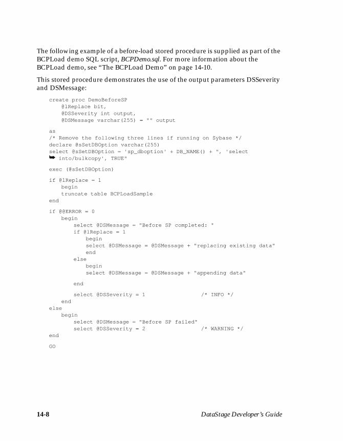
14-8 DataStage Developer’s Guide
The following example of a before-load stored procedure is supplied as part of theBCPLoad demo SQL script, BCPDemo.sql. For more information about theBCPLoad demo, see “The BCPLoad Demo” on page 14-10.
This stored procedure demonstrates the use of the output parameters DSSeverityand DSMessage:
create proc DemoBeforeSP@lReplace bit,@DSSeverity int output,@DSMessage varchar(255) = "" output
as/* Remove the following three lines if running on Sybase */declare @sSetDBOption varchar(255)select @sSetDBOption = 'sp_dboption' + DB_NAME() + ", 'select➥ into/bulkcopy', TRUE"
exec (@sSetDBOption)
if @lReplace = 1begintruncate table BCPLoadSample
end
if @@ERROR = 0begin
select @DSMessage = "Before SP completed: "if @lReplace = 1
beginselect @DSMessage = @DSMessage + "replacing existing data"end
elsebeginselect @DSMessage = @DSMessage + "appending data"
end
select @DSSeverity = 1 /* INFO */end
elsebegin
select @DSMessage = "Before SP failed"select @DSSeverity = 2 /* WARNING */
end
GO

BCPLoad Stages 14-9
To use this stored procedure, enter DemoBeforeSP 1,DSSeverity,DSMessageas the value for the Before Load Stored Procedure property when you edit thestage instance:
To use existing stored procedures, enter the name of the stored procedure andappropriate parameter values as the value for the Before Load Stored Procedureor After Load Stored Procedure property.
For example, say your stored procedure includes the following:
create proc sp_TrustyDebuggedProcedure@strTableName char(30),@strSurname char(30),@iRowCount int = 0 output
as
...
...
...
If you want to use this procedure as a before-load procedure, you would entersp_TrustyDebuggedProcedure " Table1 " , " Smith " in the Value field for theBefore Load Stored Procedure property. “Table1” and “Smith” are passed in asstrTableName and strSurname respectively.
14-10 DataStage Developer’s Guide
If you want to modify an existing stored procedure to return a severity warningand an error message, the create procedure needs to be modified to include the twooutput parameters DSSeverity and DSMessage. In the earlier example, the createprocedure would become:
create proc sp_TrustyDebuggedProcedure@strTableName char(30),@strSurname char(30),@iRowCount int = 0 output,@DSSeverity int output,@DSMessage varchar(255) = "" output
as
...
.../* Somewhere in the procedure set appropriate values for DSSeverityand DSMessage*/
In this case, you would enter the following in the Value field for the Before LoadStored Procedure:
sp_TrustyDebuggedProcedure "Table1","Smith",0,DSSeverity,DSMessage
You can include job parameters to represent the value of a stored procedure param-eter. To use job parameters in the earlier example, you would enter the followingin the Value field for the Before Load Stored Procedure:
sp_TrustyDebuggedProcedure #Table#,#Name#,0,DSSeverity,DSMessage
Table and Name are the names of two defined job parameters.
The BCPLoad DemoAs well as the BCPLoad Plug-in itself and example stored procedures, a BCPLoaddemo is also supplied. The demo is designed to show how the BCPLoad stageworks, using a simple three-stage job design.
The demo comprises three files which are found in the \BCPDEMO directory onthe DataStage CD:
• BCPDemo.txt. An exported job with associated table definitions.
• BCPDemo.sql. An SQL script that creates a demo target table in a chosendatabase on your SQL Server.
• BCPDemo.csv. A sequential file containing 5000 rows of sample data.
The BCPLoad demo job has three stages: a Sequential File stage (for the sampledata), a Transformer stage for mapping column names from the source data to thecolumn names in the target table, and a BCPLoad stage for bulk loading the datainto the target table.
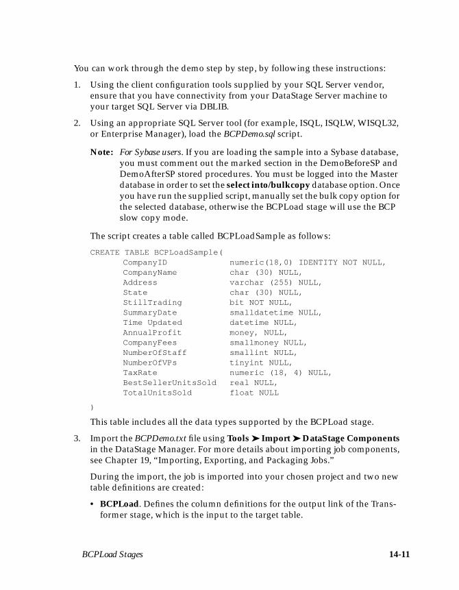
BCPLoad Stages 14-11
You can work through the demo step by step, by following these instructions:
1. Using the client configuration tools supplied by your SQL Server vendor,ensure that you have connectivity from your DataStage Server machine toyour target SQL Server via DBLIB.
2. Using an appropriate SQL Server tool (for example, ISQL, ISQLW, WISQL32,or Enterprise Manager), load the BCPDemo.sql script.
Note: For Sybase users. If you are loading the sample into a Sybase database,you must comment out the marked section in the DemoBeforeSP andDemoAfterSP stored procedures. You must be logged into the Masterdatabase in order to set the select into/bulkcopy database option. Onceyou have run the supplied script, manually set the bulk copy option forthe selected database, otherwise the BCPLoad stage will use the BCPslow copy mode.
The script creates a table called BCPLoadSample as follows:
CREATE TABLE BCPLoadSample(CompanyID numeric(18,0) IDENTITY NOT NULL,CompanyName char (30) NULL,Address varchar (255) NULL,State char (30) NULL,StillTrading bit NOT NULL,SummaryDate smalldatetime NULL,Time Updated datetime NULL,AnnualProfit money, NULL,CompanyFees smallmoney NULL,NumberOfStaff smallint NULL,NumberOfVPs tinyint NULL,TaxRate numeric (18, 4) NULL,BestSellerUnitsSold real NULL,TotalUnitsSold float NULL
)
This table includes all the data types supported by the BCPLoad stage.
3. Import the BCPDemo.txt file using Tools ➤ Import ➤ DataStage Componentsin the DataStage Manager. For more details about importing job components,see Chapter 19, “Importing, Exporting, and Packaging Jobs.”
During the import, the job is imported into your chosen project and two newtable definitions are created:
• BCPLoad. Defines the column definitions for the output link of the Trans-former stage, which is the input to the target table.
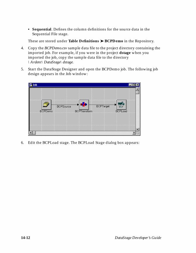
14-12 DataStage Developer’s Guide
• Sequential. Defines the column definitions for the source data in theSequential File stage.
These are stored under Table Definitions ➤ BCPDemo in the Repository.
4. Copy the BCPDemo.csv sample data file to the project directory containing theimported job. For example, if you were in the project dstage when youimported the job, copy the sample data file to the directory\Ardent\DataStage\dstage.
5. Start the DataStage Designer and open the BCPDemo job. The following jobdesign appears in the Job window:
6. Edit the BCPLoad stage. The BCPLoad Stage dialog box appears:
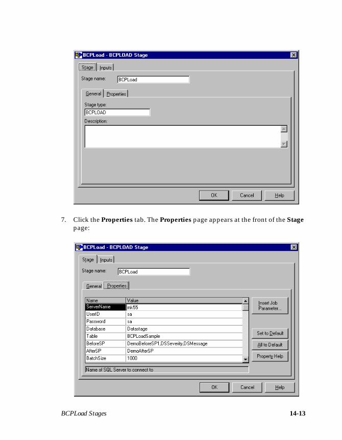
BCPLoad Stages 14-13
7. Click the Properties tab. The Properties page appears at the front of the Stagepage:
14-14 DataStage Developer’s Guide
Edit the following properties to set appropriate values:
• SQL-Server Name• User ID• Password (if required)• Database Name• Table Name
8. Click OK to close the BCPLoad Stage dialog box.
9. Recompile the job to use the new settings.
10. Start the DataStage Director and run the job. You can use a Monitor windowto monitor the rows being written. For more information, see DataStage Oper-ator’s Guide.

Orabulk Stages 15-1
15Orabulk Stages
The Orabulk stage is a Plug-in stage supplied by Ardent. It generates control anddata files for bulk loading into a single table on an Oracle target database. The filesare suitable for loading into the target database using the Oracle command sqlldr.
One input link provides a sequence of rows to load into an Oracle table. Themetadata for each input column determines how it is loaded. One optional outputlink provides a copy of all input rows to allow easy combination of this stage withother stages.
Using the Orabulk StageThe Orabulk Plug-in is preinstalled and can be used immediately. To use this Plug-in, you must insert a Plug-in stage in your job design:
1. Start the DataStage Designer and open your job design.
2. Click the Plug-in Stage icon on the toolbar. The Plug-in Stage dialog boxappears with a list of the Plug-ins installed on the DataStage server.
3. Choose Orabulk from the list box and click OK.
4. Click in the Diagram window where you want to position the stage.
Link an output from the relevant stage to the input of the Orabulk stage. Theoutput should deliver a sequence of rows. To store these rows or to process themfurther, link the output of this stage to an input of another stage. Otherwise, leavethe output of this stage unconnected.
15-2 DataStage Developer’s Guide
Renaming Columns and Converting ValuesYou cannot rename columns or convert values during an Orabulk stage. You mustdo this in an earlier stage. The column names of the input rows must match thecolumn names in the target Oracle table. See the description of the NAMEMAPstage property in “Specifying the Stage Properties” on page 15-3 for a way to mapcharacters in a column name. The data types of the columns should alsocorrespond.
Integrity ConstraintsValues for columns should satisfy any integrity constraints that will be active in theOracle database when the data is loaded, for example, values that must be nonnull,or unique, or must already exist in other tables. Otherwise, some rows may berejected when the sqlldr command is run.
Cleaning and Validating DataThe Orabulk stage does not validate data values, but it does clean up some datavalues to match the length, precision, or scale of the data type. For example, CHARand VARCHAR values are truncated on the right. DECIMAL and NUMERICvalues are rounded to their specified scale. If you want to clean data to ensure thatit matches the integrity constraints of the target table, you must do so in an earlierstage.
Orabulk Stages 15-3
Specifying the Stage PropertiesYou can specify the following properties in addition to the standard stageproperties:
Property Description
Control file name A local pathname for the Oracle sqlldr control file.
• If no value is specified, the control information is outputat the start of the data file. If there is more than one datafile, each data file gets a copy of the same controlinformation.
• If a pathname is specified, a single control file is gener-ated which can be used with any of the data filesgenerated. If the pathname has no suffix, sqlldr adds thesuffix .ctl to the pathname.
If a control file already exists, it is truncated beforeprocessing; if a control file does not exist, it is created.
Data file name A local pathname for the Oracle sqlldr data file. If thepathname has no suffix, sqlldr adds the suffix .dat to thepathname. If there is more than one data file, the files aresequentially numbered, for example, datafile1, datafile2, andso on. You can specify a position for the numbering byincluding a % character in the file name. For example, thevalue data%file produces files named data1file, data2file,and so on. If a data file already exists, it is truncated beforeprocessing; if a data file does not exist, it is created.
Oracle tablename
The name of the target table that the files are loaded into onthe Oracle database. This value must be identical to thetarget table name.
Loading mode One of the following values:
INSERT Inserts the rows into the table. It can be usedonly if the target table is empty.
APPEND Appends new rows to the table if they do notconflict with existing tables.
REPLACE Deletes existing rows in the table, using anSQL DELETE statement, before inserting thenew rows.
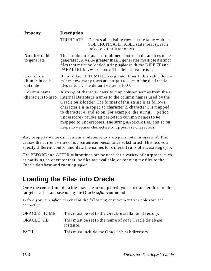
15-4 DataStage Developer’s Guide
Any property value can contain a reference to a job parameter as #param#. Thiscauses the current value of job parameter param to be substituted. This lets youspecify different control and data file names for different runs of a DataStage job.
The BEFORE and AFTER subroutines can be used for a variety of purposes, suchas notifying an operator that the files are available, or copying the files to theOracle database and running sqlldr.
Loading the Files into OracleOnce the control and data files have been completed, you can transfer them to thetarget Oracle database using the Oracle sqlldr command.
Before you run sqlldr, check that the following environment variables are setcorrectly:
TRUNCATE Deletes all existing rows in the table with anSQL TRUNCATE TABLE statement (OracleRelease 7.1 or later only).
Number of filesto generate
The number of data, or combined control and data files to begenerated. A value greater than 1 generates multiple distinctfiles that must be loaded using sqlldr with the DIRECT andPARALLEL keywords only. The default value is 1.
Size of rowchunks in eachdata file
If the value of NUMFILES is greater than 1, this value deter-mines how many rows are output to each of the distinct datafiles in turn. The default value is 1000.
Column namecharacters to map
A string of character pairs to map column names from theirinternal DataStage names to the column names used by theOracle bulk loader. The format of this string is as follows:character 1 is mapped to character 2, character 3 is mappedto character 4, and so on. For example, the string ._ (periodunderscore), causes all periods in column names to bemapped to underscores. The string aAbBcCdDeE and so onmaps lowercase characters to uppercase characters.
ORACLE_HOME This must be set to the Oracle installation directory.
ORACLE_SID This must be set to the name of your Oracle databaseinstance.
PATH This must include the Oracle bin subdirectory.
Property Description
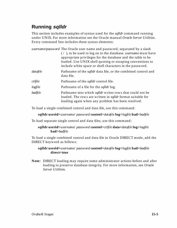
Orabulk Stages 15-5
Running sqlldrThis section includes examples of syntax used for the sqlldr command runningunder UNIX. For more information see the Oracle manual Oracle Server Utilities.Every command line includes these syntax elements:
To load a single combined control and data file, use this command:
sqlldr userid=username/password control=datafile log=logfile bad=badfile
To load separate single control and data files, use this command:
sqlldr userid=username/password control=ctlfile data=datafile log=logfilebad=badfile
To load a single combined control and data file in Oracle DIRECT mode, add theDIRECT keyword as follows:
sqlldr userid=username/password control=datafile log=logfile bad=badfiledirect=true
Note: DIRECT loading may require some administrator actions before and afterloading to preserve database integrity. For more information, see OracleServer Utilities.
username/password The Oracle user name and password, separated by a slash( / ), to be used to log on to the database. username must haveappropriate privileges for the database and the table to beloaded. Use UNIX shell quoting or escaping conventions toinclude white space or shell characters in the password.
datafile Pathname of the sqlldr data file, or the combined control anddata file.
ctlfile Pathname of the sqlldr control file.
logfile Pathname of a file for the sqlldr log.
badfile Pathname into which sqlldr writes rows that could not beloaded. The rows are written in sqlldr format suitable forloading again when any problem has been resolved.
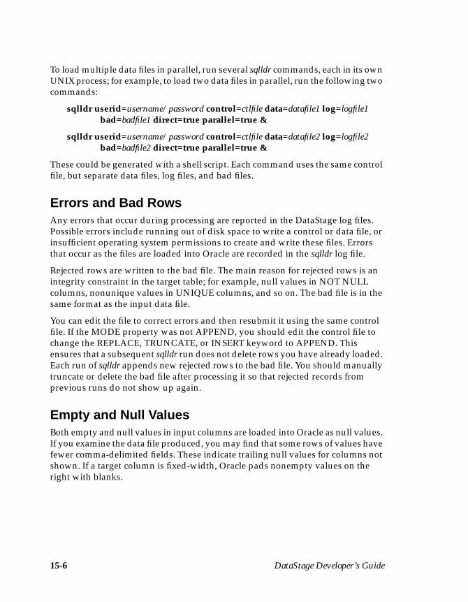
15-6 DataStage Developer’s Guide
To load multiple data files in parallel, run several sqlldr commands, each in its ownUNIX process; for example, to load two data files in parallel, run the following twocommands:
sqlldr userid=username/password control=ctlfile data=datafile1 log=logfile1bad=badfile1 direct=true parallel=true &
sqlldr userid=username/password control=ctlfile data=datafile2 log=logfile2bad=badfile2 direct=true parallel=true &
These could be generated with a shell script. Each command uses the same controlfile, but separate data files, log files, and bad files.
Errors and Bad RowsAny errors that occur during processing are reported in the DataStage log files.Possible errors include running out of disk space to write a control or data file, orinsufficient operating system permissions to create and write these files. Errorsthat occur as the files are loaded into Oracle are recorded in the sqlldr log file.
Rejected rows are written to the bad file. The main reason for rejected rows is anintegrity constraint in the target table; for example, null values in NOT NULLcolumns, nonunique values in UNIQUE columns, and so on. The bad file is in thesame format as the input data file.
You can edit the file to correct errors and then resubmit it using the same controlfile. If the MODE property was not APPEND, you should edit the control file tochange the REPLACE, TRUNCATE, or INSERT keyword to APPEND. Thisensures that a subsequent sqlldr run does not delete rows you have already loaded.Each run of sqlldr appends new rejected rows to the bad file. You should manuallytruncate or delete the bad file after processing it so that rejected records fromprevious runs do not show up again.
Empty and Null ValuesBoth empty and null values in input columns are loaded into Oracle as null values.If you examine the data file produced, you may find that some rows of values havefewer comma-delimited fields. These indicate trailing null values for columns notshown. If a target column is fixed-width, Oracle pads nonempty values on theright with blanks.
Programming in DataStage 16-1
16Programmingin DataStage
This chapter describes the programming tasks that you can perform in DataStage.At the heart of all programming in DataStage is the BASIC language. For moreinformation about BASIC syntax, see “Syntax Help for Functions and Statements”in DataStage Developer’s Help.
There are several areas within DataStage where you may need to enter some code:
• Defining custom transforms. The function specified in a transform defini-tion converts the data in a chosen column. See “Transforms” on page 11-14for details.
• Defining custom routines to use as building blocks within other program-ming tasks. For example, you may define a routine which will then bereused by several custom transforms. This chapter tells you how to view,edit, and create your own BASIC routines using the DataStage Manager.
• Defining derivations, key expressions, and constraints while editing aTransformer stage. See “The DataStage Expression Editor” on page 11-12for details.
• Defining before-stage and after-stage subroutines. These subroutinesperform an action before or after a stage has processed data. These subrou-tines can be specified for Aggregator, Transformer, and some Plug-instages. See Chapter 11, Chapter 12, and Chapter 13 for details.
• Defining before-job and after-job subroutines. These subroutines performan action before or after a job is run and are set as job properties. For moreinformation, see “Job Properties” on page 5-30.
• Defining job control routines. These subroutines can be used to controlother jobs from within the current job. For more information, see “Job Prop-erties” on page 5-30.
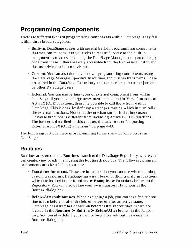
16-2 DataStage Developer’s Guide
Programming ComponentsThere are different types of programming components within DataStage. They fallwithin three broad categories:
• Built-in. DataStage comes with several built-in programming componentsthat you can reuse within your jobs as required. Some of the built-incomponents are accessible using the DataStage Manager, and you can copycode from these. Others are only accessible from the Expression Editor, andthe underlying code is not visible.
• Custom. You can also define your own programming components usingthe DataStage Manager, specifically routines and custom transforms. Theseare stored in the DataStage Repository and can be reused for other jobs andby other DataStage users.
• External. You can use certain types of external component from withinDataStage. If you have a large investment in custom UniVerse functions orActiveX (OLE) functions, then it is possible to call these from withinDataStage. This is done by defining a wrapper routine which in turn callsthe external functions. Note that the mechanism for including customUniVerse functions is different from including ActiveX (OLE) functions.The former is described in this chapter, the latter under “ImportingExternal ActiveX (OLE) Functions” on page 4-43.
The following sections discuss programming terms you will come across inDataStage.
RoutinesRoutines are stored in the Routines branch of the DataStage Repository, where youcan create, view or edit them using the Routine dialog box. The following programcomponents are classified as routines:
• Transform functions. These are functions that you can use when definingcustom transforms. DataStage has a number of built-in transform functionswhich are located in the Routines ➤ Examples ➤ Functions branch of theRepository. You can also define your own transform functions in theRoutine dialog box.
• Before/After subroutines. When designing a job, you can specify a subrou-tine to run before or after the job, or before or after an active stage.DataStage has a number of built-in before/after subroutines, which arelocated in the Routines ➤ Built-in ➤ Before/After branch in the Reposi-tory. You can also define your own before/after subroutines using theRoutine dialog box.
Programming in DataStage 16-3
• Custom UniVerse functions. These are specialized BASIC functions thathave been defined outside DataStage. Using the Routine dialog box, youcan get DataStage to create a wrapper that enables you to call these func-tions from within DataStage. These functions are stored under theRoutines branch in the Repository. You specify the category when youcreate the routine.
• ActiveX (OLE) functions. You can use ActiveX (OLE) functions asprogramming components within DataStage. Such functions are madeaccessible to DataStage by importing them. This creates a wrapper thatenables you to call the functions. After import, you can view and edit theBASIC wrapper using the Routine dialog box. By default, such functionsare located in the Routines ➤ Class name branch in the Repository, but youcan specify your own category when importing the functions.
When using the Expression Editor, all of these components appear under the DSRoutines… command on the Suggest Operand menu.
A special case of routine is the job control routine. Such a routine is used to set upa DataStage job that controls other DataStage jobs. Job control routines are speci-fied in the Job control page on the Job Properties dialog box. Job control routinesare not stored under the Routines branch in the Repository.
FunctionsFunctions take arguments and return a value. The word “function” is applied tomany components in DataStage:
• BASIC functions. These are one of the fundamental building blocks of theBASIC language. When using the Expression Editor, you can access theBASIC functions via the Function… command on the Suggest Operandmenu.
• DataStage BASIC functions. These are special BASIC functions that arespecific to DataStage. These are mostly used in job control routines.DataStage functions begin with DS to distinguish them from generalBASIC functions. When using the Expression Editor, you can access theDataStage BASIC functions via the DS Functions… command on theSuggest Operand menu.
The following items, although called “functions”, are classified as routines and aredescribed under “Routines” on page 16-2. When using the Expression Editor, theyall appear under the DS Routines… command on the Suggest Operand menu.
• Transform functions• Custom UniVerse functions• ActiveX (OLE) functions
16-4 DataStage Developer’s Guide
ExpressionsAn expression is an element of code that defines a value. The word “expression” isused both as a specific part of BASIC syntax, and to describe portions of code thatyou can enter when defining a job. Areas of DataStage where you can use suchexpressions are:
• Defining breakpoints in the debugger
• Defining column derivations, key expressions and constraints in Trans-former stages
• Defining a custom transform
In each of these cases the DataStage Expression Editor guides you as to whatprogramming elements you can insert into the expression.
SubroutinesA subroutine is a set of instructions that perform a specific task. Subroutines do notreturn a value. The word “subroutine” is used both as a specific part of BASICsyntax, but also to refer particularly to before/after subroutines which carry outtasks either before or after a job or an active stage. DataStage has many built-inbefore/after subroutines, or you can define your own.
Before/after subroutines are included under the general routine classification asthey are accessible under the Routines branch in the Repository.
MacrosDataStage has a number of built-in macros. These can be used in expressions, jobcontrol routines, and before/after subroutines. The available macros are concernedwith ascertaining job status.
When using the Expression Editor, they all appear under the DS Macro…command on the Suggest Operand menu.
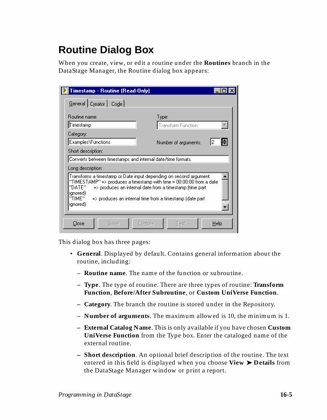
Programming in DataStage 16-5
Routine Dialog BoxWhen you create, view, or edit a routine under the Routines branch in theDataStage Manager, the Routine dialog box appears:
This dialog box has three pages:
• General. Displayed by default. Contains general information about theroutine, including:
– Routine name. The name of the function or subroutine.
– Type. The type of routine. There are three types of routine: TransformFunction, Before/After Subroutine, or Custom UniVerse Function.
– Category. The branch the routine is stored under in the Repository.
– Number of arguments. The maximum allowed is 10, the minimum is 1.
– External Catalog Name. This is only available if you have chosen CustomUniVerse Function from the Type box. Enter the cataloged name of theexternal routine.
– Short description. An optional brief description of the routine. The textentered in this field is displayed when you choose View ➤ Details fromthe DataStage Manager window or print a report.
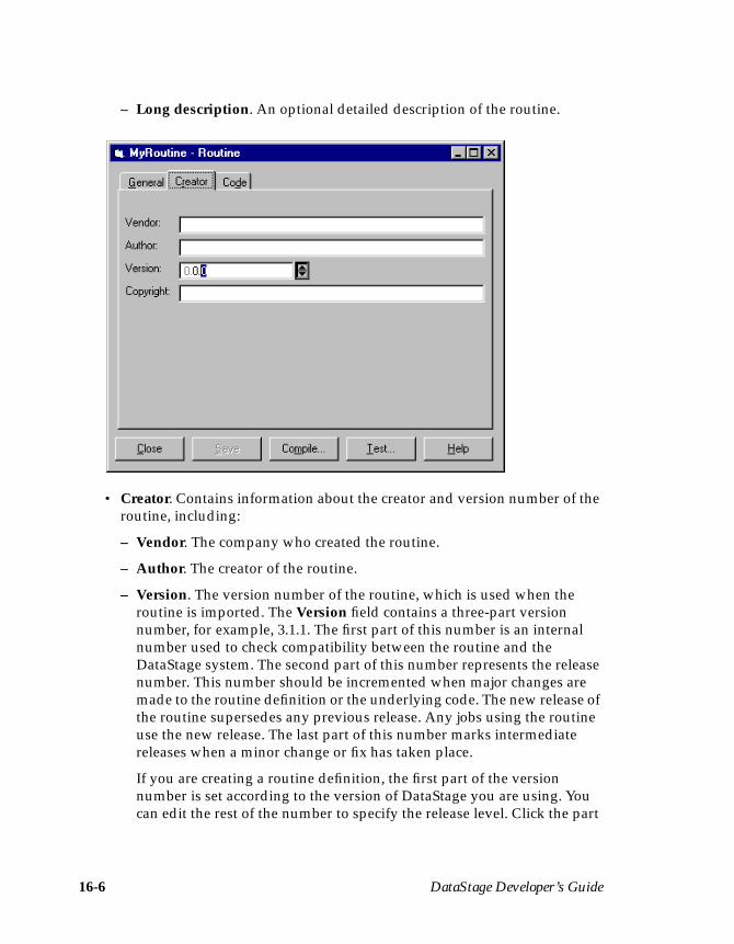
16-6 DataStage Developer’s Guide
– Long description. An optional detailed description of the routine.
• Creator. Contains information about the creator and version number of theroutine, including:
– Vendor. The company who created the routine.
– Author. The creator of the routine.
– Version. The version number of the routine, which is used when theroutine is imported. The Version field contains a three-part versionnumber, for example, 3.1.1. The first part of this number is an internalnumber used to check compatibility between the routine and theDataStage system. The second part of this number represents the releasenumber. This number should be incremented when major changes aremade to the routine definition or the underlying code. The new release ofthe routine supersedes any previous release. Any jobs using the routineuse the new release. The last part of this number marks intermediatereleases when a minor change or fix has taken place.
If you are creating a routine definition, the first part of the versionnumber is set according to the version of DataStage you are using. Youcan edit the rest of the number to specify the release level. Click the part
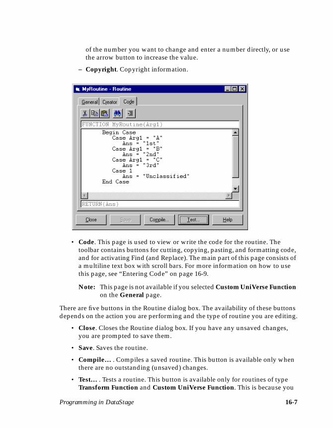
Programming in DataStage 16-7
of the number you want to change and enter a number directly, or usethe arrow button to increase the value.
– Copyright. Copyright information.
• Code. This page is used to view or write the code for the routine. Thetoolbar contains buttons for cutting, copying, pasting, and formatting code,and for activating Find (and Replace). The main part of this page consists ofa multiline text box with scroll bars. For more information on how to usethis page, see “Entering Code” on page 16-9.
Note: This page is not available if you selected Custom UniVerse Functionon the General page.
There are five buttons in the Routine dialog box. The availability of these buttonsdepends on the action you are performing and the type of routine you are editing.
• Close. Closes the Routine dialog box. If you have any unsaved changes,you are prompted to save them.
• Save. Saves the routine.
• Compile… . Compiles a saved routine. This button is available only whenthere are no outstanding (unsaved) changes.
• Test… . Tests a routine. This button is available only for routines of typeTransform Function and Custom UniVerse Function. This is because you
16-8 DataStage Developer’s Guide
cannot test before-subroutines and after-subroutines in isolation. Thisbutton is active only when the routine has compiled or referencedsuccessfully.
• Help. Invokes the Help system.
Creating a RoutineTo create a new routine, select the Routines branch in the DataStage Managerwindow and do one of the following:
• Choose File ➤ New Routine… .• Choose New Routine… from the shortcut menu.• Click the New icon on the toolbar.
The Routine dialog box appears. On the General page:
1. Enter the name of the function or subroutine in the Routine name field. Thisshould not be the same as any BASIC function name.
2. Choose the type of routine you want to create from the Type drop-down listbox. There are three options:
• Transform Function. Choose this if you want to create a routine for aTransform definition.
• Before/After Subroutine. Choose this if you want to create a routine for abefore-stage or after-stage subroutine or a before-job or after-jobsubroutine.
• Custom UniVerse Function. Choose this if you want to refer to an externalroutine, rather than define one in this dialog. If you choose this, the Codepage will not be available.
3. Enter a category name in the Category field. This name is used to create abranch under the main Routines branch. If you do not enter a name in thisfield, the routine is created under the main Routines branch.
4. Specify the number of arguments in the Number of arguments box. Thenumber of arguments is set to 2 (and cannot be edited) for a routine type ofBefore/After Subroutine. The number of arguments is set to 1 by default for aroutine type of Transform Function or External Function, but you canincrease this number using the arrow buttons.
5. Enter a brief description of the routine in the Short description field. This isan optional field. The text entered here is displayed when you choose View ➤Details from the DataStage Manager window.

Programming in DataStage 16-9
6. Enter a more detailed description of the routine in the Long description field.This is also an optional field.
Once this page is complete, you can enter creator information on the Creator page,but this is optional. You must then enter your code on the Code page.
Entering CodeYou can enter or edit code for a routine on the Code page in the Routine dialog box.
The first field on this page displays the routine name and the number of argu-ments. If you want to change these properties, you must edit the fields on theGeneral page.
The main part of this page contains a multiline text entry box, in which you mustenter your code. To enter code, click in the box and start typing. You can use thefollowing standard Windows edit functions in this text box:
• Delete using the Del key• Cut using Ctrl-X• Copy using Ctrl-C• Paste using Ctrl-V• Go to the end of the line using the End key• Go to the beginning of the line using the Home key• Select text by clicking and dragging or double-clicking
Some of these edit functions are included in a shortcut menu which you candisplay by clicking the right mouse button. You can also cut, copy, and paste codeusing the icons in the toolbar.
Your code must only contain BASIC functions and statements supported byDataStage. If you are unsure of the supported functions and statements, or thecorrect syntax to use, see DataStage Developer’s Help for a complete list ofsupported DataStage BASIC functions.
If you want to format your code, click the Format icon on the toolbar.
The last field on this page displays the return statement for the function or subrou-tine. You cannot edit this field.
Saving CodeWhen you have finished entering or editing your code, the routine must be saved.A routine cannot be compiled or tested if it has not been saved. To save a routine,click Save in the Routine dialog box. The routine properties (its name, description,number of arguments, and creator information) and the associated code are savedin the Repository.
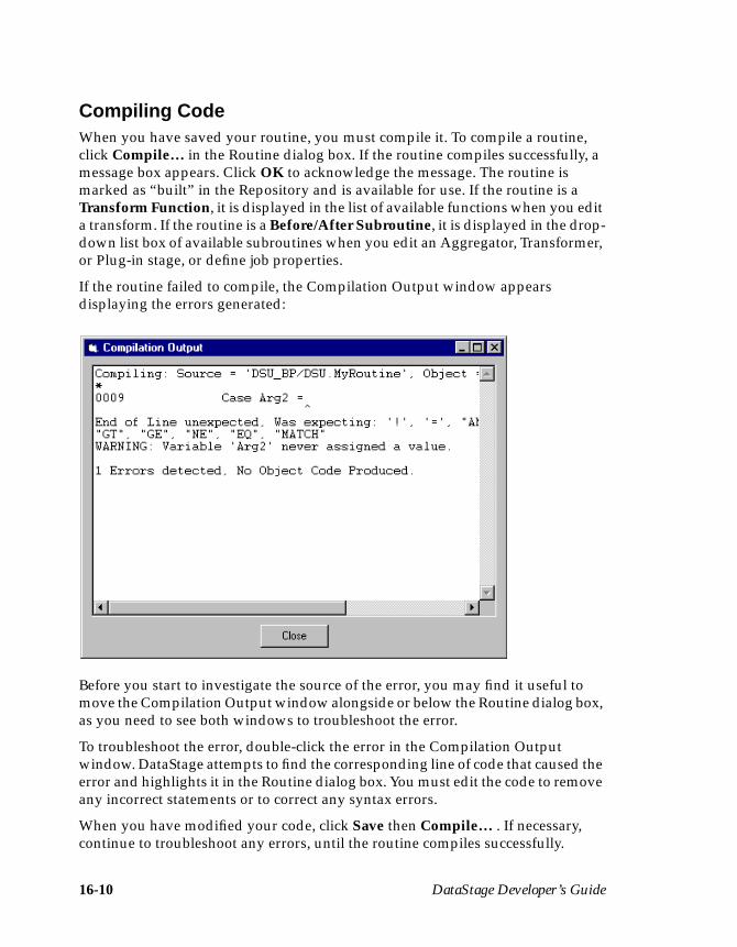
16-10 DataStage Developer’s Guide
Compiling CodeWhen you have saved your routine, you must compile it. To compile a routine,click Compile… in the Routine dialog box. If the routine compiles successfully, amessage box appears. Click OK to acknowledge the message. The routine ismarked as “built” in the Repository and is available for use. If the routine is aTransform Function, it is displayed in the list of available functions when you edita transform. If the routine is a Before/After Subroutine, it is displayed in the drop-down list box of available subroutines when you edit an Aggregator, Transformer,or Plug-in stage, or define job properties.
If the routine failed to compile, the Compilation Output window appearsdisplaying the errors generated:
Before you start to investigate the source of the error, you may find it useful tomove the Compilation Output window alongside or below the Routine dialog box,as you need to see both windows to troubleshoot the error.
To troubleshoot the error, double-click the error in the Compilation Outputwindow. DataStage attempts to find the corresponding line of code that caused theerror and highlights it in the Routine dialog box. You must edit the code to removeany incorrect statements or to correct any syntax errors.
When you have modified your code, click Save then Compile… . If necessary,continue to troubleshoot any errors, until the routine compiles successfully.
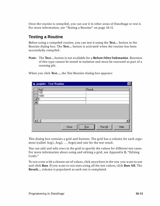
Programming in DataStage 16-11
Once the routine is compiled, you can use it in other areas of DataStage or test it.For more information, see “Testing a Routine” on page 16-11.
Testing a RoutineBefore using a compiled routine, you can test it using the Test… button in theRoutine dialog box. The Test… button is activated when the routine has beensuccessfully compiled.
Note: The Test… button is not available for a Before/After Subroutine. Routinesof this type cannot be tested in isolation and must be executed as part of arunning job.
When you click Test…, the Test Routine dialog box appears:
This dialog box contains a grid and buttons. The grid has a column for each argu-ment (called Arg1, Arg2, … Argn) and one for the test result.
You can add and edit rows in the grid to specify the values for different test cases.For more information about using and editing a grid, see Appendix B, “EditingGrids.”
To run a test with a chosen set of values, click anywhere in the row you want to useand click Run. If you want to run tests using all the test values, click Run All. TheResult… column is populated as each test is completed.
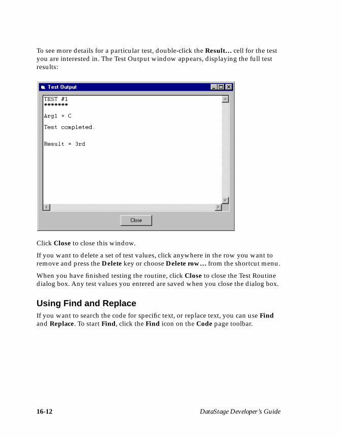
16-12 DataStage Developer’s Guide
To see more details for a particular test, double-click the Result… cell for the testyou are interested in. The Test Output window appears, displaying the full testresults:
Click Close to close this window.
If you want to delete a set of test values, click anywhere in the row you want toremove and press the Delete key or choose Delete row… from the shortcut menu.
When you have finished testing the routine, click Close to close the Test Routinedialog box. Any test values you entered are saved when you close the dialog box.
Using Find and ReplaceIf you want to search the code for specific text, or replace text, you can use Findand Replace. To start Find, click the Find icon on the Code page toolbar.
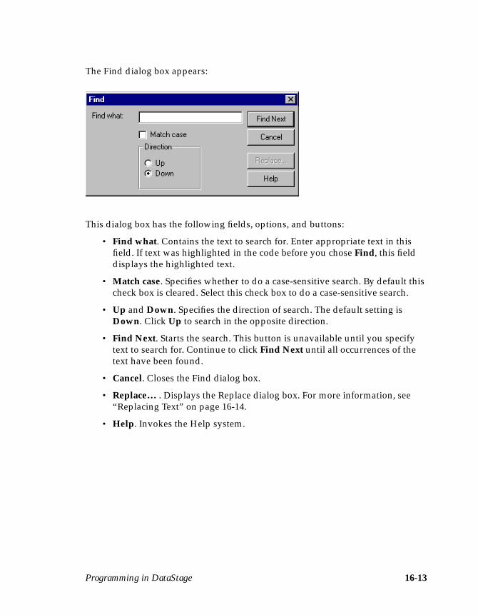
Programming in DataStage 16-13
The Find dialog box appears:
This dialog box has the following fields, options, and buttons:
• Find what. Contains the text to search for. Enter appropriate text in thisfield. If text was highlighted in the code before you chose Find, this fielddisplays the highlighted text.
• Match case. Specifies whether to do a case-sensitive search. By default thischeck box is cleared. Select this check box to do a case-sensitive search.
• Up and Down. Specifies the direction of search. The default setting isDown. Click Up to search in the opposite direction.
• Find Next. Starts the search. This button is unavailable until you specifytext to search for. Continue to click Find Next until all occurrences of thetext have been found.
• Cancel. Closes the Find dialog box.
• Replace… . Displays the Replace dialog box. For more information, see“Replacing Text” on page 16-14.
• Help. Invokes the Help system.
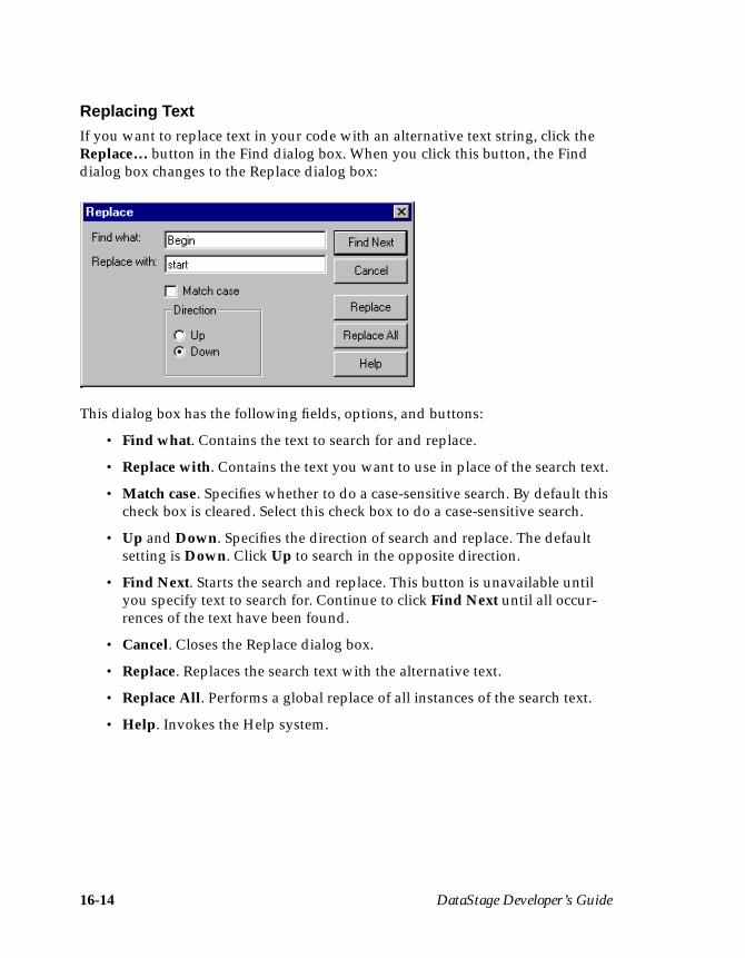
16-14 DataStage Developer’s Guide
Replacing TextIf you want to replace text in your code with an alternative text string, click theReplace… button in the Find dialog box. When you click this button, the Finddialog box changes to the Replace dialog box:
This dialog box has the following fields, options, and buttons:
• Find what. Contains the text to search for and replace.
• Replace with. Contains the text you want to use in place of the search text.
• Match case. Specifies whether to do a case-sensitive search. By default thischeck box is cleared. Select this check box to do a case-sensitive search.
• Up and Down. Specifies the direction of search and replace. The defaultsetting is Down. Click Up to search in the opposite direction.
• Find Next. Starts the search and replace. This button is unavailable untilyou specify text to search for. Continue to click Find Next until all occur-rences of the text have been found.
• Cancel. Closes the Replace dialog box.
• Replace. Replaces the search text with the alternative text.
• Replace All. Performs a global replace of all instances of the search text.
• Help. Invokes the Help system.
Programming in DataStage 16-15
Viewing and Editing a RoutineYou can view and edit any user-written functions and subroutines in your project.To view or modify a function or subroutine, select the function or subroutine in thedisplay area and do one of the following:
• Choose File ➤ Properties… .• Choose Properties… from the shortcut menu.• Click the Properties icon on the toolbar.• Double-click the function or subroutine in the display area.
The Routine dialog box appears. You can edit any of the fields and options on anyof the pages. If you make any changes, you must save, compile, and test the codebefore closing the Routine dialog box. See earlier in this chapter for moreinformation.
Copying a RoutineYou can copy an existing routine using the DataStage Manager. To copy a routine,select it in the display area and do one of the following:
• Choose File ➤ Copy.• Choose Copy from the shortcut menu.• Click the Copy icon on the toolbar.
The routine is copied and a new routine is created under the same branch in theproject tree. By default, the name of the copy is called CopyOfXXX, where XXX isthe name of the chosen routine. An edit box appears allowing you to rename thecopy immediately. The new routine must be compiled before it can be used.
Renaming a RoutineYou can rename any of the existing routines using the DataStage Manager. Torename an item, select it in the display area and do one of the following:
• Click the routine again. An edit box appears and you can enter a differentname or edit the existing one. Save the new name by pressing Enter or byclicking outside the edit box.
• Choose File ➤ Rename. An edit box appears and you can enter a differentname or edit the existing one. Save the new name by pressing Enter or byclicking outside the edit box.
16-16 DataStage Developer’s Guide
• Choose Rename from the shortcut menu. An edit box appears and you canenter a different name or edit the existing one. Save the new name bypressing Enter or by clicking outside the edit box.
• Double-click the routine. The Routine dialog box appears and you can editthe Routine name field. Click Save, then Close.
Debugging, Compiling, and Releasing a Job 17-1
17Debugging, Compiling,
and Releasing a Job
This chapter describes how to create and release an executable job. When you haveedited all the stages in a job design, you can create an executable job by compilingyour job design. The debugger helps you to iron out any problems in your design.The job can then be validated and run using the DataStage Director.
If you want to ship the executable job to another DataStage system, you mustrelease the job before packaging it for deployment. For more information aboutpackaging a job, see Chapter 19, “Importing, Exporting, and Packaging Jobs.”
The DataStage DebuggerThe DataStage debugger provides basic facilities for testing and debugging yourjob designs. The debugger is run from the DataStage Designer. It can be used froma number of places within the Designer:
• The Debug menu (File ➤ Debug)• Debugger toolbar• Shortcut menu (some items)
The debugger enables you to set breakpoints on the links in your job. When yourun the job in debug mode, the job will stop when it reaches a breakpoint. You canthen step to the next action (reading or writing) on that link, or step to theprocessing of the next row of data (which may be on the same link or another link).
Any breakpoints you have set remain if the job is closed and reopened. Break-points are validated when the job is compiled, and remain valid if the link to whichit belongs is moved, or has either end moved, or is renamed. If, however, a link isdeleted and another of the same name created, the new link does not inherit thebreakpoint. Breakpoints are not inherited when a job is saved under a differentname, exported, or upgraded.
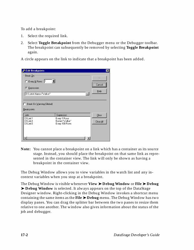
17-2 DataStage Developer’s Guide
To add a breakpoint:
1. Select the required link.
2. Select Toggle Breakpoint from the Debugger menu or the Debugger toolbar.The breakpoint can subsequently be removed by selecting Toggle Breakpointagain.
A circle appears on the link to indicate that a breakpoint has been added.
Note: You cannot place a breakpoint on a link which has a container as its sourcestage. Instead, you should place the breakpoint on that same link as repre-sented in the container view. The link will only be shown as having abreakpoint in the container view.
The Debug Window allows you to view variables in the watch list and any in-context variables when you stop at a breakpoint.
The Debug Window is visible whenever View ➤ Debug Window or File ➤ Debug➤ Debug Window is selected. It always appears on the top of the DataStageDesigner window. Right-clicking in the Debug Window invokes a shortcut menucontaining the same items as the File ➤ Debug menu. The Debug Window has twodisplay panes. You can drag the splitter bar between the two panes to resize themrelative to one another. The window also gives information about the status of thejob and debugger.

Debugging, Compiling, and Releasing a Job 17-3
The upper pane shows local variables. Before debugging starts, all the columns onall the links in the job are displayed, and all are marked “Out of context”. Duringdebugging, the pane shows only the variables that are in context when the job isstopped at a breakpoint. It displays the names and values of any variablescurrently in context and you can add any of these variables to the watch list, whichmaintains a record of selected variables for as long as required.
The lower pane displays variables in the watch list. When variables are in context,their values are displayed and updated at every breakpoint. When variables areout of context, they are marked “Out of context”. The watch list is saved betweensessions.
To add a variable to the watch list:
1. Select the variable name in the upper pane of the Debug Window.
2. Click Add Watch. The variable will be added to the watch list and will appearin the lower pane.
To delete variables from the watch list, select the variables and click RemoveWatch.
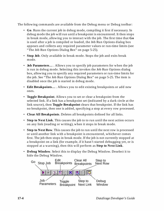
17-4 DataStage Developer’s Guide
The following commands are available from the Debug menu or Debug toolbar:
• Go. Runs the current job in debug mode, compiling it first if necessary. Indebug mode the job will run until a breakpoint is encountered. It then stopsin break mode, allowing you to interact with the job. The first time that Gois used after a job is compiled or loaded, the Job Run Options dialog boxappears and collects any required parameter values or run-time limits (see“The Job Run Options Dialog Box” on page 5-25).
• Stop Job. Only available in break mode. Stops the job and exits breakmode.
• Job Parameters… . Allows you to specify job parameters for when the jobis run in debug mode. Selecting this invokes the Job Run Options dialogbox, allowing you to specify any required parameters or run-time limits forthe job. See “The Job Run Options Dialog Box” on page 5-25. The item isdisabled once the job is started in debug mode.
• Edit Breakpoints… . Allows you to edit existing breakpoints or add newones.
• Toggle Breakpoint. Allows you to set or clear a breakpoint from theselected link. If a link has a breakpoint set (indicated by a dark circle at thelink source), then Toggle Breakpoint clears that breakpoint. If the link hasno breakpoint, then one is added, specifying a stop at every row processed.
• Clear All Breakpoints. Deletes all breakpoints defined for all links.
• Step to Next Link. This causes the job to to run until the next action occurson any link (reading or writing), when it stops in break mode.
• Step to Next Row. This causes the job to run until the next row is processedor until another link with a breakpoint is encountered, whichever comesfirst. The job then stops in break mode. If the job is not currently stopped ata breakpoint on a link (for example, if it hasn’t started debugging yet, or isstopped at a warning), then this will perform as Step to Next Link.
• Debug Window. Select this to display the Debug Window. Deselect it tohide the Debug Window.
Go Stop Job
Job
Edit
ToggleParameters Breakpoint
BreakpointsClear AllBreakpoints
Step toNext Link
Step toNext Row
DebugWindow
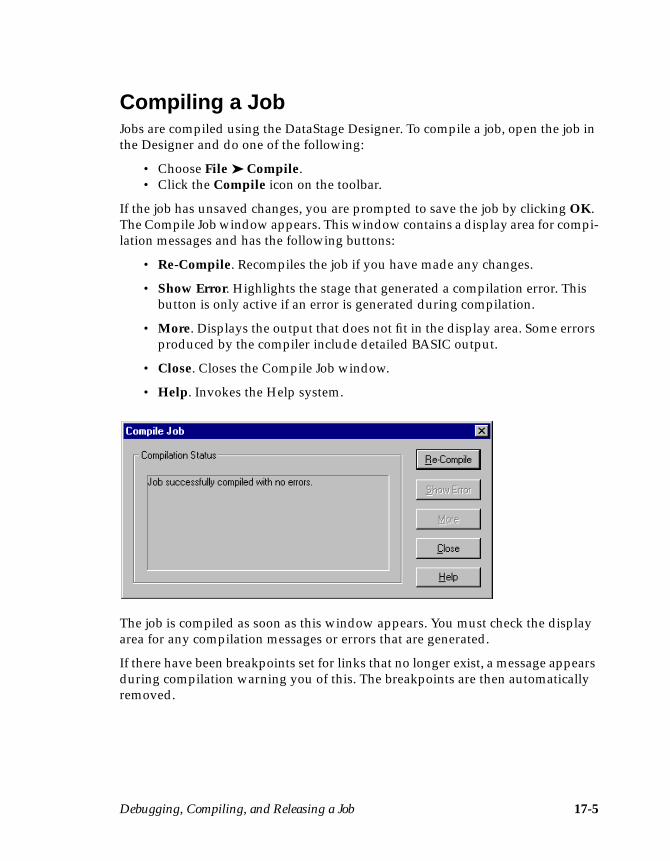
Debugging, Compiling, and Releasing a Job 17-5
Compiling a JobJobs are compiled using the DataStage Designer. To compile a job, open the job inthe Designer and do one of the following:
• Choose File ➤ Compile.• Click the Compile icon on the toolbar.
If the job has unsaved changes, you are prompted to save the job by clicking OK.The Compile Job window appears. This window contains a display area for compi-lation messages and has the following buttons:
• Re-Compile. Recompiles the job if you have made any changes.
• Show Error. Highlights the stage that generated a compilation error. Thisbutton is only active if an error is generated during compilation.
• More. Displays the output that does not fit in the display area. Some errorsproduced by the compiler include detailed BASIC output.
• Close. Closes the Compile Job window.
• Help. Invokes the Help system.
The job is compiled as soon as this window appears. You must check the displayarea for any compilation messages or errors that are generated.
If there have been breakpoints set for links that no longer exist, a message appearsduring compilation warning you of this. The breakpoints are then automaticallyremoved.
17-6 DataStage Developer’s Guide
Compilation ChecksDuring compilation, the following criteria in the job design are checked:
• Primary Input. If you have more than one input link to a Transformerstage, the compiler checks that one is defined as the primary input link.
• Reference Input. If you have reference inputs defined in a Transformerstage, the compiler checks that these are not from sequential files.
• Key Expressions. If you have key fields specified in your column defini-tions, the compiler checks that there are key expressions joining the datatables.
• Transforms. If you have specified a transform, the compiler checks that thisis a suitable transform for the data type.
Successful CompilationIf the Compile Job window displays the message Job successfullycompiled with no errors. you can:
• Validate the job• Run or schedule the job• Release the job• Package the job for deployment on other DataStage systems
Jobs are validated and run using the DataStage Director. See DataStage Operator’sGuide for more information.
TroubleshootingIf the Compile Job window displays an error, you can use the Show Error buttonto troubleshoot your job design. When you click the Show Error button, the stagethat contains the first error in the design is highlighted. You must edit the stage tochange any incorrect settings and recompile.
The process of troubleshooting compilation errors is an iterative process. You mustrefine each “problem” stage until the job compiles successfully.
Debugging, Compiling, and Releasing a Job 17-7
Releasing a JobIf you are developing a job for users on another DataStage system, you must labelthe job as ready for deployment before you can package it. For more informationabout packaging a job, see Chapter 19, “Importing, Exporting, and PackagingJobs.”
To label a job for deployment, you must release it. A job is ready for release whenit has been compiled and validated successfully.
Jobs are released using the DataStage Manager. To release a job:
1. Start the DataStage Manager and enter your logon details in the Attach toProject dialog box.
2. Double-click the Jobs branch in the project tree.
3. Select the job you want to release in the display area.
4. Choose Tools ➤ Release job. Note that the job must not be open in theDataStage Designer or Director.
A physical copy of the chosen job is made (along with all the routines and coderequired to run the job). The released job is automatically assigned a name andversion number using the format jobname%reln.n.n. jobname is the name of the jobyou chose to release and n.n.n is the version number.
You can use the Designer to view the design of a released job. However, if you editthe job design you cannot save the changes. The metadata and settings displayedin the job design are stored as part of the released job and these may not match theinformation currently held in the Repository. This is especially true if you devel-oped the table definitions, transforms, routines, or job design after the job wasreleased.
If you want to develop and enhance a job design, you must edit the original job. Touse the changes you have made, you must release the job again.
Note: Released jobs cannot be copied or renamed using the Manager.

17-8 DataStage Developer’s Guide

Reporting and Printing 18-1
18Reporting and Printing
This chapter describes how to generate reports from the DataStage Manager. It alsodescribes how to print from the Designer.
ReportingThe DataStage Reporting Tool is flexible and allows you to generate reports atvarious levels within a project, for example, entire job, single stage, set of stages,etc.
Information generated for reporting purposes is stored in a relational database onthe DataStage client. This information can then be used to print a report, write areport to a file, or be interrogated by a third-party tool.
A Microsoft MS Access database is provided on the DataStage client for thispurpose. It offers a number of predefined report formats for you to choose from.You can extend or customize this database, or use some other SQL database forthese purposes. It is possible to target any SQL database which is supported by aLevel 2-compliant ODBC driver on the client machine. Create database scripts formost popular databases are provided in the main client directory on the DataStageclient (by default, \ardent\datastage\clients).
The Reporting ToolThe DataStage Reporting Tool is invoked by choosing Tools ➤ Reporting Assis-tant… from the DataStage Manager. The Reporting Assistant dialog box appears.This dialog box has two pages: Schema Update and Update Options.
Note: If you want to use the Reporting Tool you should ensure that the names ofyour DataStage components (jobs, stage, links etc.) do not exceed 64characters.
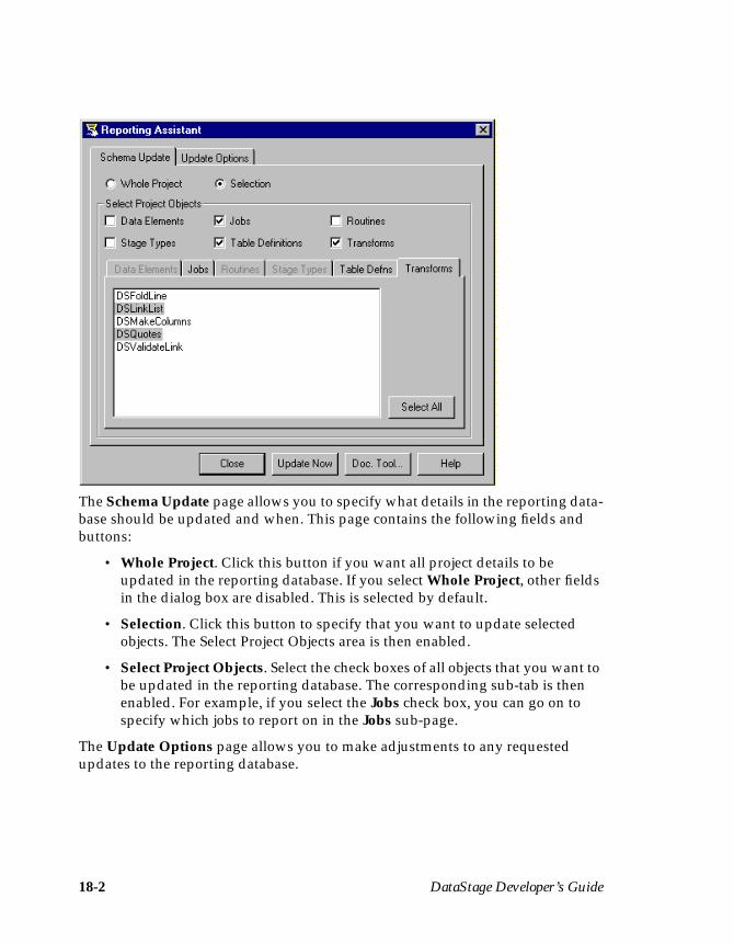
18-2 DataStage Developer’s Guide
The Schema Update page allows you to specify what details in the reporting data-base should be updated and when. This page contains the following fields andbuttons:
• Whole Project. Click this button if you want all project details to beupdated in the reporting database. If you select Whole Project, other fieldsin the dialog box are disabled. This is selected by default.
• Selection. Click this button to specify that you want to update selectedobjects. The Select Project Objects area is then enabled.
• Select Project Objects. Select the check boxes of all objects that you want tobe updated in the reporting database. The corresponding sub-tab is thenenabled. For example, if you select the Jobs check box, you can go on tospecify which jobs to report on in the Jobs sub-page.
The Update Options page allows you to make adjustments to any requestedupdates to the reporting database.
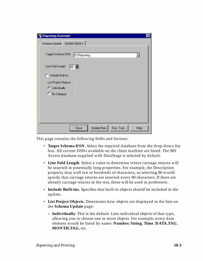
Reporting and Printing 18-3
This page contains the following fields and buttons:
• Target Schema DSN. Select the required database from the drop-down listbox. All current DSNs available on the client machine are listed. The MSAccess database supplied with DataStage is selected by default.
• Line Fold Length. Select a value to determine where carriage returns willbe inserted in potentially long properties. For example, the Descriptionproperty may well run to hundreds of characters, so selecting 80 wouldspecify that carriage returns are inserted every 80 characters. If there arealready carriage returns in the text, these will be used in preference.
• Include Built-ins. Specifies that built-in objects should be included in theupdate.
• List Project Objects. Determines how objects are displayed in the lists onthe Schema Update page:
– Individually. This is the default. Lists individual objects of that type,allowing you to choose one or more objects. For example, every dataelement would be listed by name: Number, String, Time, DATA.TAG,MONTH.TAG, etc.
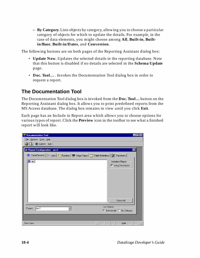
18-4 DataStage Developer’s Guide
– By Category. Lists objects by category, allowing you to choose a particularcategory of objects for which to update the details. For example, in thecase of data elements, you might choose among All, Built-in, Built-in/Base, Built-in/Dates, and Conversion.
The following buttons are on both pages of the Reporting Assistant dialog box:
• Update Now. Updates the selected details in the reporting database. Notethat this button is disabled if no details are selected in the Schema Updatepage.
• Doc. Tool… . Invokes the Documentation Tool dialog box in order torequest a report.
The Documentation ToolThe Documentation Tool dialog box is invoked from the Doc. Tool… button on theReporting Assistant dialog box. It allows you to print predefined reports from theMS Access database. The dialog box remains in view until you click Exit.
Each page has an Include in Report area which allows you to choose options forvarious types of report. Click the Preview icon in the toolbar to see what a finishedreport will look like.
Reporting and Printing 18-5
The toolbar has the following functions:
• Print. Prints a report of the format specified in the Report Configurationform.
• Print Preview. Gets a preview of the form before you actually print it. Toprint from the preview, click the Print button.
• Custom Reports. Gets a list of available reports. Use this to access reportsadded to the MS Access Documentation Tool besides those supplied withDataStage.
• Exit. Exits the Documentation Tool when you have printed all requiredreports.
The Documentation Tool dialog box has a Report Configuration form which inturn has a page for every type of object. Each page has a list box that lists all objectsof that type currently in the reporting database. Objects can be listed individuallyor by category (note that jobs can only be listed individually).
The Report Configuration form has the following fields and buttons:
• Include in Report. This area lists the optional fields that can be excluded orincluded in the report. Check the box to include an item in the report, clearit to exclude it. All items are checked by default.
• Select All. Selects all items in the list window.
• Project. Lists all the available projects. Choose the project that you want toreport on.
• List Objects. This area determines how objects are displayed in the lists onthe Schema Update page:
– Individually. This is the default. Lists individual objects of that type,allowing you to choose one or more objects. For example, every dataelement would be listed by name: Number, String, Time, DATA.TAG,MONTH.TAG, etc.
– By Category. Lists objects by category, allowing you to choose a particularcategory of objects for which to update the details. For example, in thecase of data elements, you might choose among All, Built-in, Built-in/Base, Built-in/Dates, and Conversion.
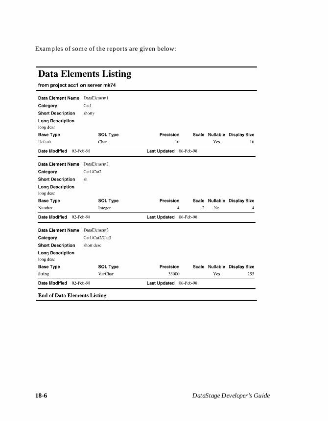
18-6 DataStage Developer’s Guide
Examples of some of the reports are given below:
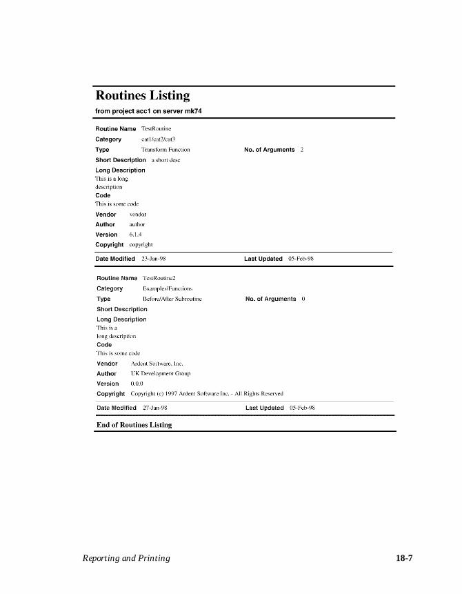
Reporting and Printing 18-7
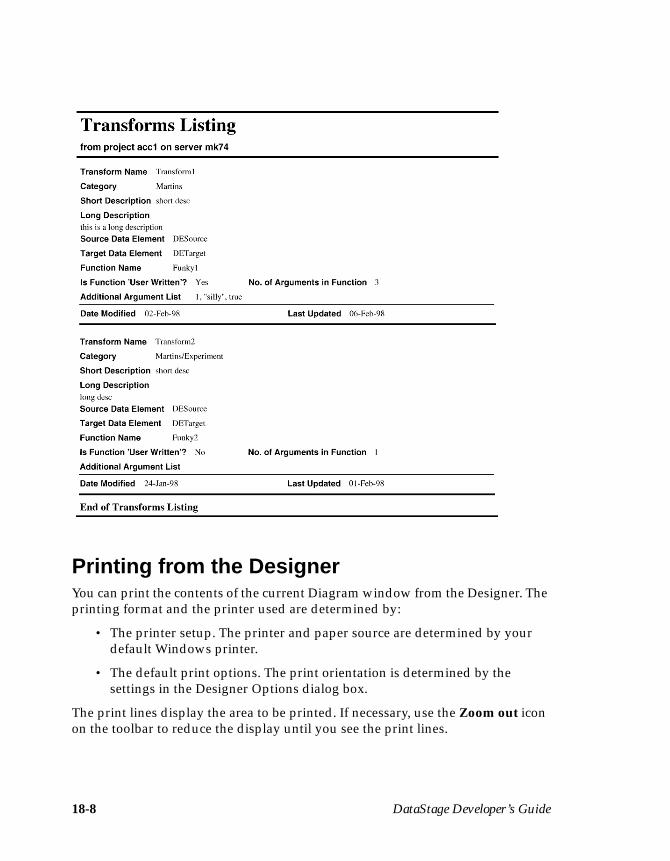
18-8 DataStage Developer’s Guide
Printing from the DesignerYou can print the contents of the current Diagram window from the Designer. Theprinting format and the printer used are determined by:
• The printer setup. The printer and paper source are determined by yourdefault Windows printer.
• The default print options. The print orientation is determined by thesettings in the Designer Options dialog box.
The print lines display the area to be printed. If necessary, use the Zoom out iconon the toolbar to reduce the display until you see the print lines.
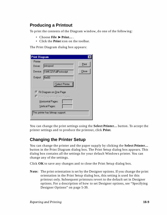
Reporting and Printing 18-9
Producing a PrintoutTo print the contents of the Diagram window, do one of the following:
• Choose File ➤ Print… .• Click the Print icon on the toolbar.
The Print Diagram dialog box appears:
You can change the print settings using the Select Printer… button. To accept theprinter settings and to produce the printout, click Print.
Changing the Printer SetupYou can change the printer and the paper supply by clicking the Select Printer…button in the Print Diagram dialog box. The Print Setup dialog box appears. Thisdialog box contains all the settings for your default Windows printer. You canchange any of the settings.
Click OK to save any changes and to close the Print Setup dialog box.
Note: The print orientation is set by the Designer options. If you change the printorientation in the Print Setup dialog box, this setting is used for thisprintout only. Subsequent printouts revert to the default set in Designeroptions. For a description of how to set Designer options, see “SpecifyingDesigner Options” on page 5-39.

18-10 DataStage Developer’s Guide
Importing, Exporting, and Packaging Jobs 19-1
19Importing, Exporting, and
Packaging Jobs
There are two situations where you may need to move or deploy DataStagecomponents to another DataStage system:
• To continue the development of a job. In this case, you must ensure that allthe components used by the job are copied to the new system. This is doneby using Export. The components are installed into the new Repositoryusing Import.
• To distribute an executable job or a Plug-in. In this case, you must packagethe components you want to deploy using the Packager Wizard. End usersinstall the packaged job or component using the installation programdescribed in DataStage Administrator’s Guide.
This chapter describes how to use the DataStage Manager to perform these tasks.
Using ImportYou can import complete projects, jobs, or job components that have been exportedfrom another DataStage development environment. The exported components arecontained in a text file. You must copy this text file to a directory you can accessfrom your local machine.
To use the Import option:
1. Start the DataStage Manager and enter your logon details in the Attach toProject dialog box. The DataStage Manager window appears.
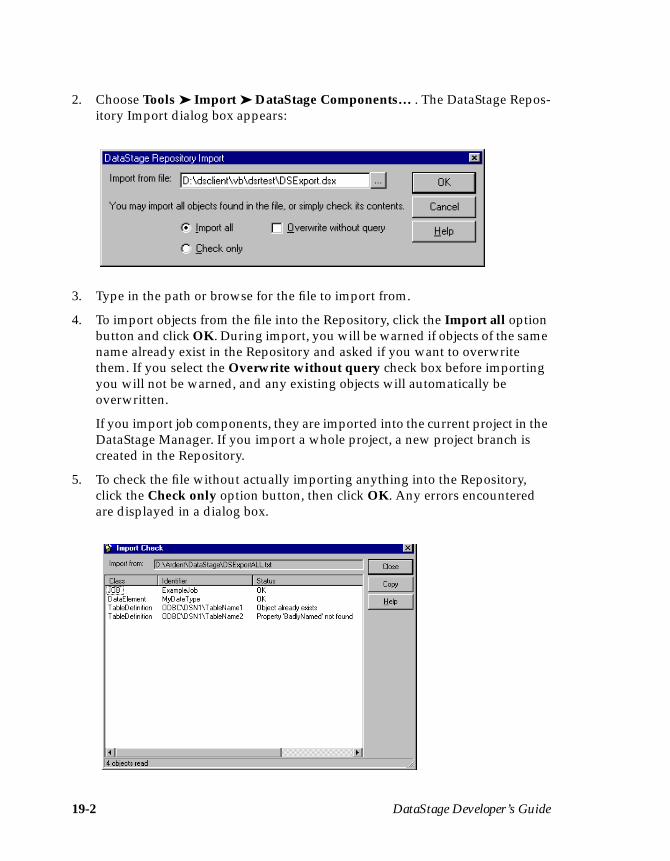
19-2 DataStage Developer’s Guide
2. Choose Tools ➤ Import ➤ DataStage Components… . The DataStage Repos-itory Import dialog box appears:
3. Type in the path or browse for the file to import from.
4. To import objects from the file into the Repository, click the Import all optionbutton and click OK. During import, you will be warned if objects of the samename already exist in the Repository and asked if you want to overwritethem. If you select the Overwrite without query check box before importingyou will not be warned, and any existing objects will automatically beoverwritten.
If you import job components, they are imported into the current project in theDataStage Manager. If you import a whole project, a new project branch iscreated in the Repository.
5. To check the file without actually importing anything into the Repository,click the Check only option button, then click OK. Any errors encounteredare displayed in a dialog box.

Importing, Exporting, and Packaging Jobs 19-3
Using ExportIf you want to move a project or job components to another development environ-ment, you must use the Export option in the DataStage Manager. Exported projectsor components are stored in text files. You must choose what to export and the fileto use.
To use the Export option:
1. Start the DataStage Manager and enter your logon details in the Attach toProject dialog box. The DataStage Manager window appears.
2. Choose Tools ➤ Export… . The Export dialog box appears:
3. Choose the file to export to by doing one of the following:
• Enter the directory path and file name in the Export to file field.
• Click … (browse) to search the system for an appropriate directory and file.
4. Select the Append to existing file check box if you want to add the exporteditems to the specified file. The check box is cleared by default, i.e., theexported items will overwrite any existing items in the file.

19-4 DataStage Developer’s Guide
5. Choose what to export by clicking the appropriate option button:
• Whole project. All the jobs, data elements, stage types, table definitions,and transforms are exported.
• Selection. An individual item or a selection of items in the current projectis exported.
6. If you clicked Selection, choose the items to export by selecting the appro-priate check boxes:
• Job designs. The chosen job designs are exported.
• Data elements. The chosen data elements are exported.
• Stage types. The chosen Plug-in definitions are exported.
Note: The Export option does not handle the associated Plug-in DLLs. Todeploy a Plug-in, you must use the Packager Wizard instead. Formore information, see “Using the Packager Wizard” on page 19-6.
• Table definitions. The chosen table definitions are exported.
• Transforms. The chosen transforms are exported.
• Job executables. The chosen job executables are exported. If you choosethis option, you can also select the Program sources check box to export theassociated source.
• Routines. The chosen routines are exported. If you choose this option, youcan also select the Source Code check box to export the associated sourcecode.
A selection is already made based on the highlighted branch in the DataStageManager when you chose Tools ➤ Export… .
By default, for objects other than job designs and job executables, you canselect all objects of a particular type to be exported or select a category of objectto export from the drop-down list. For example, in the case of data elements,you might choose among All, Built-In, Built-In/Base, Built-In/Dates, andConversion.
It is possible to choose an individual object, but you must first click By indi-vidual component on the Options page.
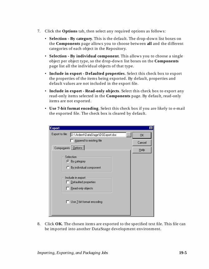
Importing, Exporting, and Packaging Jobs 19-5
7. Click the Options tab, then select any required options as follows:
• Selection - By category. This is the default. The drop-down list boxes onthe Components page allows you to choose between all and the differentcategories of each object in the Repository.
• Selection - By individual component. This allows you to choose a singleobject per object type, so the drop-down list boxes on the Componentspage list all the individual objects of that type.
• Include in export - Defaulted properties. Select this check box to exportthe properties of the items being exported. By default, properties anddefault values are not included in the export file.
• Include in export - Read-only objects. Select this check box to export anyread-only items selected in the Components page. By default, read-onlyitems are not exported.
• Use 7-bit format encoding. Select this check box if you are likely to e-mailthe exported file. The check box is cleared by default.
8. Click OK. The chosen items are exported to the specified text file. This file canbe imported into another DataStage development environment.
19-6 DataStage Developer’s Guide
Using the Packager WizardIf you have developed a job or Plug-in, you can distribute it to other DataStagesystems using the Packager Wizard. This utility is run from the Manager.
When you use the Packager Wizard, you must specify the type of package tocreate:
• Job Deployment. Contains executable job definitions (for each job in thepackage). The package contains information about the job itself and otherdependencies such as transforms, data elements, and Plug-ins.
Note: You can only package released jobs. For more information aboutreleasing a job, see Chapter 17, “Debugging, Compiling, andReleasing a Job.”
• Design Component. Contains Plug-in definitions and associated DLLs.
Note that, if you are packaging jobs that include routines using external ActiveXcomponents, then the actual ActiveX components are not included in the package.It is your responsibility to ensure that the ActiveX components are deployed on thetarget system.
To package a job or Plug-in:
1. Start the DataStage Manager and enter your logon details in the Attach toProject dialog box. The DataStage Manager window appears.
2. Choose Tools ➤ Packager Wizard… . The DataStage Packager Wizard dialogbox appears:
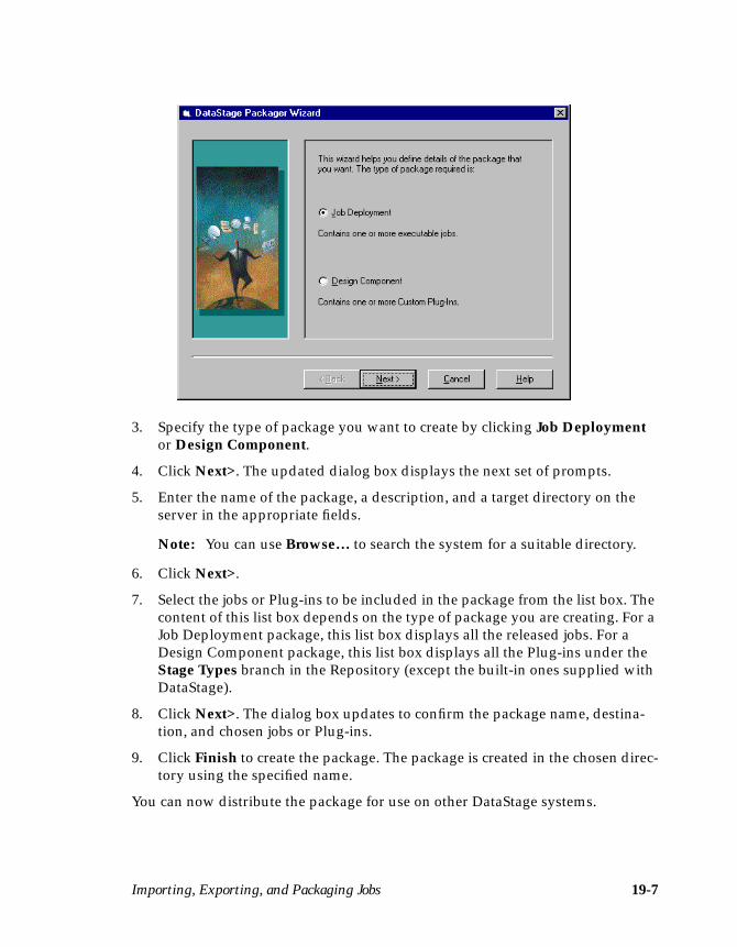
Importing, Exporting, and Packaging Jobs 19-7
3. Specify the type of package you want to create by clicking Job Deploymentor Design Component.
4. Click Next>. The updated dialog box displays the next set of prompts.
5. Enter the name of the package, a description, and a target directory on theserver in the appropriate fields.
Note: You can use Browse… to search the system for a suitable directory.
6. Click Next>.
7. Select the jobs or Plug-ins to be included in the package from the list box. Thecontent of this list box depends on the type of package you are creating. For aJob Deployment package, this list box displays all the released jobs. For aDesign Component package, this list box displays all the Plug-ins under theStage Types branch in the Repository (except the built-in ones supplied withDataStage).
8. Click Next>. The dialog box updates to confirm the package name, destina-tion, and chosen jobs or Plug-ins.
9. Click Finish to create the package. The package is created in the chosen direc-tory using the specified name.
You can now distribute the package for use on other DataStage systems.

19-8 DataStage Developer’s Guide
Built-in Transforms and Routines A-1
ABuilt-in Transforms
and Routines
This appendix describes the built-in transforms and routines supplied withDataStage.
When you edit a Transformer stage, you can convert your data using one of thebuilt-in transforms supplied with DataStage. Alternatively, you can convert yourdata using your own custom transforms. Custom transforms can convert datausing functions or routines.
For more information about editing a Transformer stage or creating custom trans-forms, see Chapter 11, “Transformer Stages.” For a complete list of the supportedBASIC functions, see DataStage Developer’s Help. For details on how to write auser-written routine, see Chapter 16, “Programming in DataStage.”
Built-in TransformsYou can view the definitions of the built-in transforms using the DataStageManager. For ease of reference, the transforms are listed according to their result(output) data element.
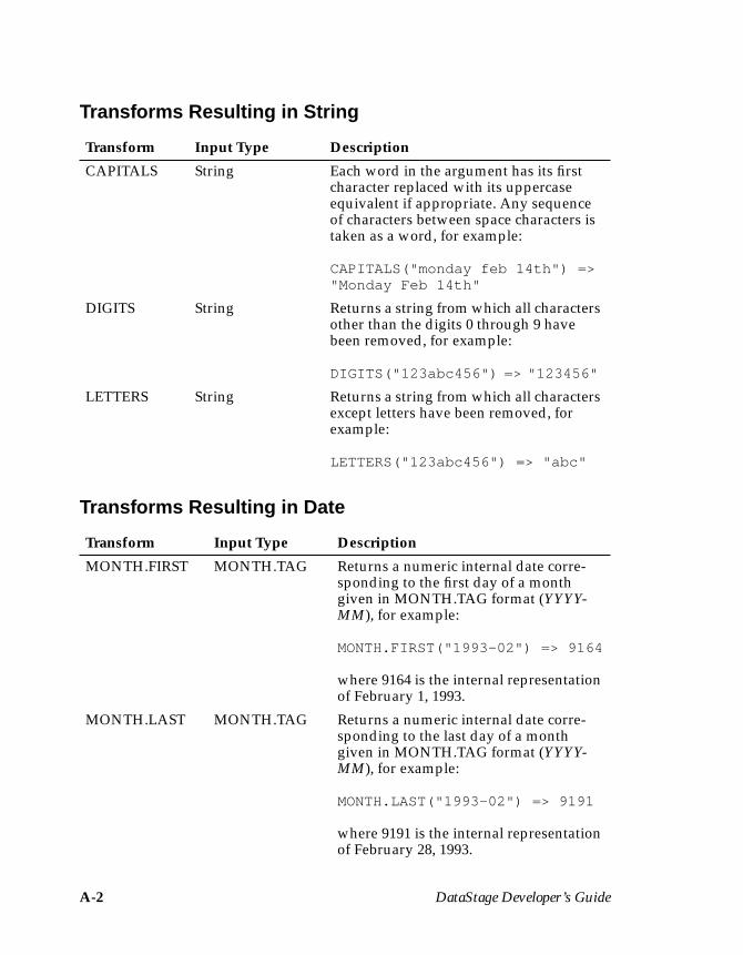
A-2 DataStage Developer’s Guide
Transforms Resulting in String
Transforms Resulting in Date
Transform Input Type Description
CAPITALS String Each word in the argument has its firstcharacter replaced with its uppercaseequivalent if appropriate. Any sequenceof characters between space characters istaken as a word, for example:
CAPITALS("monday feb 14th") =>"Monday Feb 14th"
DIGITS String Returns a string from which all charactersother than the digits 0 through 9 havebeen removed, for example:
DIGITS("123abc456") => "123456"
LETTERS String Returns a string from which all charactersexcept letters have been removed, forexample:
LETTERS("123abc456") => "abc"
Transform Input Type Description
MONTH.FIRST MONTH.TAG Returns a numeric internal date corre-sponding to the first day of a monthgiven in MONTH.TAG format (YYYY-MM), for example:
MONTH.FIRST("1993-02") => 9164
where 9164 is the internal representationof February 1, 1993.
MONTH.LAST MONTH.TAG Returns a numeric internal date corre-sponding to the last day of a monthgiven in MONTH.TAG format (YYYY-MM), for example:
MONTH.LAST("1993-02") => 9191
where 9191 is the internal representationof February 28, 1993.
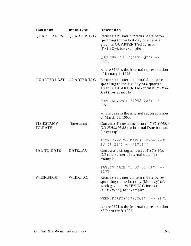
Built-in Transforms and Routines A-3
QUARTER.FIRST QUARTER.TAG Returns a numeric internal date corre-sponding to the first day of a quartergiven in QUARTER.TAG format(YYYYQn), for example:
QUARTER.FIRST("1993Q2") =>9133
where 9133 is the internal representationof January 1, 1993.
QUARTER.LAST QUARTER.TAG Returns a numeric internal date corre-sponding to the last day of a quartergiven in QUARTER.TAG format (YYYY-MM), for example:
QUARTER.LAST("1993-02") =>9222
where 9222 is the internal representationof March 31, 1993.
TIMESTAMP.TO.DATE
Timestamp Converts Timestamp format (YYYY-MM-DD HH:MM:SS) to Internal Date format,for example:
TIMESTAMP.TO.DATE("1996-12-0513:46:21") => "10567"
TAG.TO.DATE DATE.TAG Converts a string in format YYYY-MM-DD to a numeric internal date, forexample:
TAG.TO.DATE("1993-02-14") =>9177
WEEK.FIRST WEEK.TAG Returns a numeric internal date corre-sponding to the first day (Monday) of aweek given in WEEK.TAG format(YYYYWnn), for example:
WEEK.FIRST("1993W06") => 9171
where 9171 is the internal representationof February 8, 1993.
Transform Input Type Description
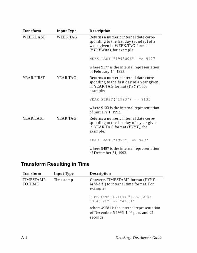
A-4 DataStage Developer’s Guide
Transform Resulting in Time
WEEK.LAST WEEK.TAG Returns a numeric internal date corre-sponding to the last day (Sunday) of aweek given in WEEK.TAG format(YYYYWnn), for example:
WEEK.LAST("1993W06") => 9177
where 9177 is the internal representationof February 14, 1993.
YEAR.FIRST YEAR.TAG Returns a numeric internal date corre-sponding to the first day of a year givenin YEAR.TAG format (YYYY), forexample:
YEAR.FIRST("1993") => 9133
where 9133 is the internal representationof January 1, 1993.
YEAR.LAST YEAR.TAG Returns a numeric internal date corre-sponding to the last day of a year givenin YEAR.TAG format (YYYY), forexample:
YEAR.LAST("1993") => 9497
where 9497 is the internal representationof December 31, 1993.
Transform Input Type Description
TIMESTAMP.TO.TIME
Timestamp Converts TIMESTAMP format (YYYY-MM-DD) to internal time format. Forexample:
TIMESTAMP.TO.TIME( " 1996-12-0513:46:21 " ) => " 49581 "
where 49581 is the internal representationof December 5 1996, 1.46 p.m. and 21seconds.
Transform Input Type Description
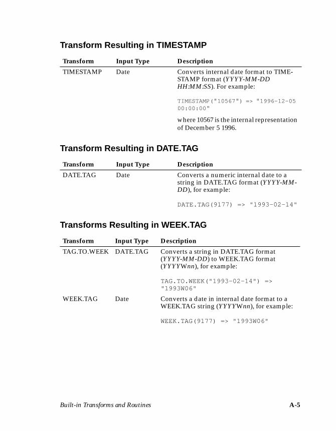
Built-in Transforms and Routines A-5
Transform Resulting in TIMESTAMP
Transform Resulting in DATE.TAG
Transforms Resulting in WEEK.TAG
Transform Input Type Description
TIMESTAMP Date Converts internal date format to TIME-STAMP format (YYYY-MM-DDHH:MM:SS). For example:
TIMESTAMP(" 10567 " ) => " 1996-12-0500:00:00 "
where 10567 is the internal representationof December 5 1996.
Transform Input Type Description
DATE.TAG Date Converts a numeric internal date to astring in DATE.TAG format (YYYY-MM-DD), for example:
DATE.TAG(9177) => "1993-02-14"
Transform Input Type Description
TAG.TO.WEEK DATE.TAG Converts a string in DATE.TAG format(YYYY-MM-DD) to WEEK.TAG format(YYYYWnn), for example:
TAG.TO.WEEK("1993-02-14") =>"1993W06"
WEEK.TAG Date Converts a date in internal date format to aWEEK.TAG string (YYYYWnn), for example:
WEEK.TAG(9177) => "1993W06"
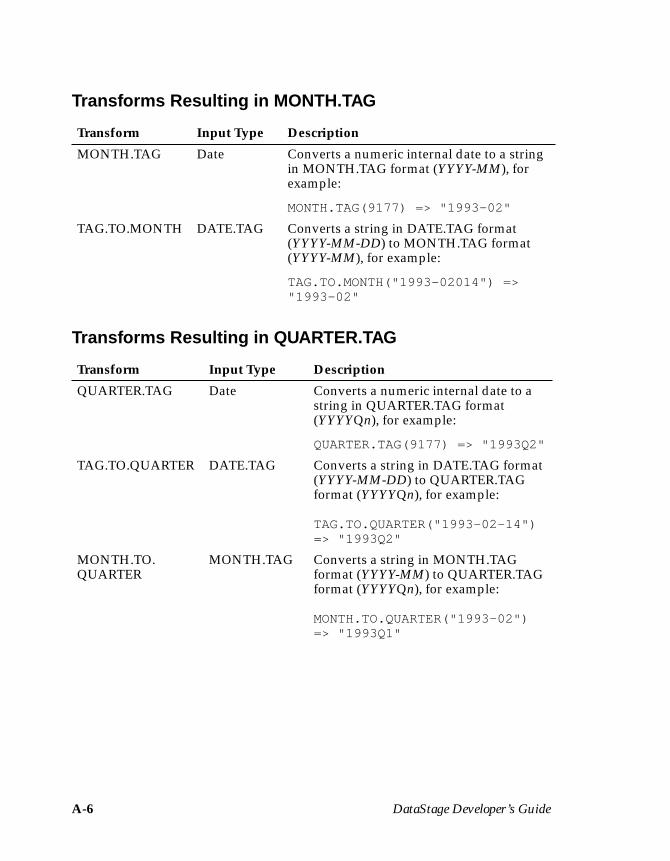
A-6 DataStage Developer’s Guide
Transforms Resulting in MONTH.TAG
Transforms Resulting in QUARTER.TAG
Transform Input Type Description
MONTH.TAG Date Converts a numeric internal date to a stringin MONTH.TAG format (YYYY-MM), forexample:
MONTH.TAG(9177) => "1993-02"
TAG.TO.MONTH DATE.TAG Converts a string in DATE.TAG format(YYYY-MM-DD) to MONTH.TAG format(YYYY-MM), for example:
TAG.TO.MONTH("1993-02014") =>"1993-02"
Transform Input Type Description
QUARTER.TAG Date Converts a numeric internal date to astring in QUARTER.TAG format(YYYYQn), for example:
QUARTER.TAG(9177) => "1993Q2"
TAG.TO.QUARTER DATE.TAG Converts a string in DATE.TAG format(YYYY-MM-DD) to QUARTER.TAGformat (YYYYQn), for example:
TAG.TO.QUARTER("1993-02-14")=> "1993Q2"
MONTH.TO.QUARTER
MONTH.TAG Converts a string in MONTH.TAGformat (YYYY-MM) to QUARTER.TAGformat (YYYYQn), for example:
MONTH.TO.QUARTER("1993-02")=> "1993Q1"
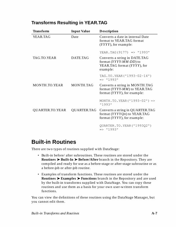
Built-in Transforms and Routines A-7
Transforms Resulting in YEAR.TAG
Built-in RoutinesThere are two types of routines supplied with DataStage:
• Built-in before/after subroutines. These routines are stored under theRoutines ➤ Built-In ➤ Before/After branch in the Repository. They arecompiled and ready for use as a before-stage or after-stage subroutine or asa before-job or after-job routine.
• Examples of transform functions. These routines are stored under theRoutines ➤ Examples ➤ Functions branch in the Repository and are usedby the built-in transforms supplied with DataStage. You can copy theseroutines and use them as a basis for your own user-written transformfunctions.
You can view the definitions of these routines using the DataStage Manager, butyou cannot edit them.
Transform Input Value Description
YEAR.TAG Date Converts a date in internal Dateformat to YEAR.TAG format(YYYY), for example:
YEAR.TAG(9177) => "1993"
TAG.TO.YEAR DATE.TAG Converts a string in DATE.TAGformat (YYYY-MM-DD) toYEAR.TAG format (YYYY), forexample:
TAG.TO.YEAR("1993-02-14")=> "1993"
MONTH.TO.YEAR MONTH.TAG Converts a string in MONTH.TAGformat (YYYY-MM) to YEAR.TAGformat (YYYY), for example:
MONTH.TO.YEAR("1993-02") =>"1993"
QUARTER.TO.YEAR QUARTER.TAG Converts a string in QUARTER.TAGformat (YYYYQn) to YEAR.TAGformat (YYYY), for example:
QUARTER.TO.YEAR("1993Q2")=> "1993"
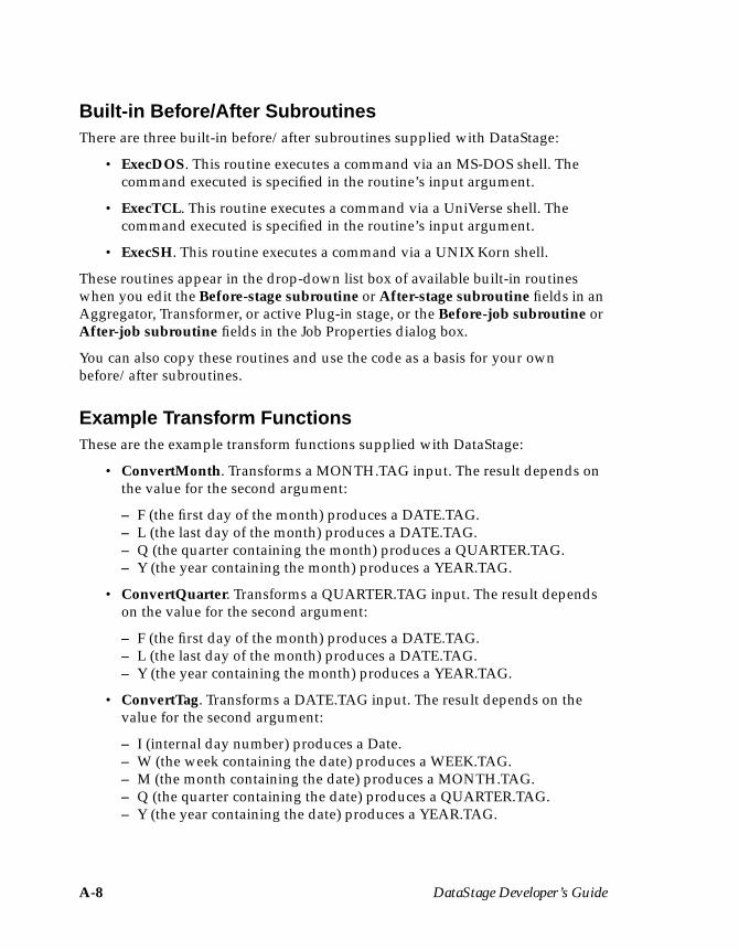
A-8 DataStage Developer’s Guide
Built-in Before/After SubroutinesThere are three built-in before/after subroutines supplied with DataStage:
• ExecDOS. This routine executes a command via an MS-DOS shell. Thecommand executed is specified in the routine’s input argument.
• ExecTCL. This routine executes a command via a UniVerse shell. Thecommand executed is specified in the routine’s input argument.
• ExecSH. This routine executes a command via a UNIX Korn shell.
These routines appear in the drop-down list box of available built-in routineswhen you edit the Before-stage subroutine or After-stage subroutine fields in anAggregator, Transformer, or active Plug-in stage, or the Before-job subroutine orAfter-job subroutine fields in the Job Properties dialog box.
You can also copy these routines and use the code as a basis for your ownbefore/after subroutines.
Example Transform FunctionsThese are the example transform functions supplied with DataStage:
• ConvertMonth. Transforms a MONTH.TAG input. The result depends onthe value for the second argument:
– F (the first day of the month) produces a DATE.TAG.– L (the last day of the month) produces a DATE.TAG.– Q (the quarter containing the month) produces a QUARTER.TAG.– Y (the year containing the month) produces a YEAR.TAG.
• ConvertQuarter. Transforms a QUARTER.TAG input. The result dependson the value for the second argument:
– F (the first day of the month) produces a DATE.TAG.– L (the last day of the month) produces a DATE.TAG.– Y (the year containing the month) produces a YEAR.TAG.
• ConvertTag. Transforms a DATE.TAG input. The result depends on thevalue for the second argument:
– I (internal day number) produces a Date.– W (the week containing the date) produces a WEEK.TAG.– M (the month containing the date) produces a MONTH.TAG.– Q (the quarter containing the date) produces a QUARTER.TAG.– Y (the year containing the date) produces a YEAR.TAG.
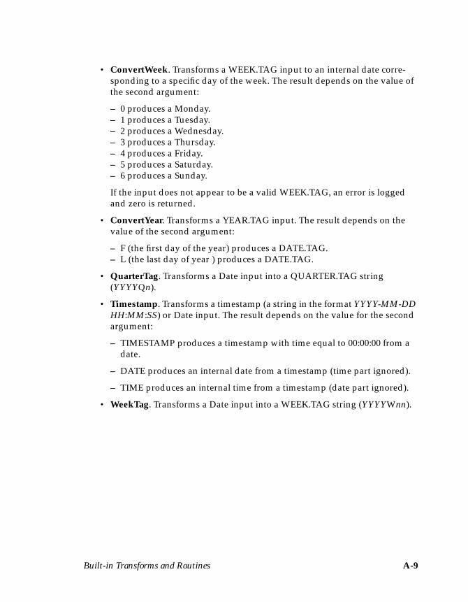
Built-in Transforms and Routines A-9
• ConvertWeek. Transforms a WEEK.TAG input to an internal date corre-sponding to a specific day of the week. The result depends on the value ofthe second argument:
– 0 produces a Monday.– 1 produces a Tuesday.– 2 produces a Wednesday.– 3 produces a Thursday.– 4 produces a Friday.– 5 produces a Saturday.– 6 produces a Sunday.
If the input does not appear to be a valid WEEK.TAG, an error is loggedand zero is returned.
• ConvertYear. Transforms a YEAR.TAG input. The result depends on thevalue of the second argument:
– F (the first day of the year) produces a DATE.TAG.– L (the last day of year ) produces a DATE.TAG.
• QuarterTag. Transforms a Date input into a QUARTER.TAG string(YYYYQn).
• Timestamp. Transforms a timestamp (a string in the format YYYY-MM-DDHH:MM:SS) or Date input. The result depends on the value for the secondargument:
– TIMESTAMP produces a timestamp with time equal to 00:00:00 from adate.
– DATE produces an internal date from a timestamp (time part ignored).
– TIME produces an internal time from a timestamp (date part ignored).
• WeekTag. Transforms a Date input into a WEEK.TAG string (YYYYWnn).

A-10 DataStage Developer’s Guide
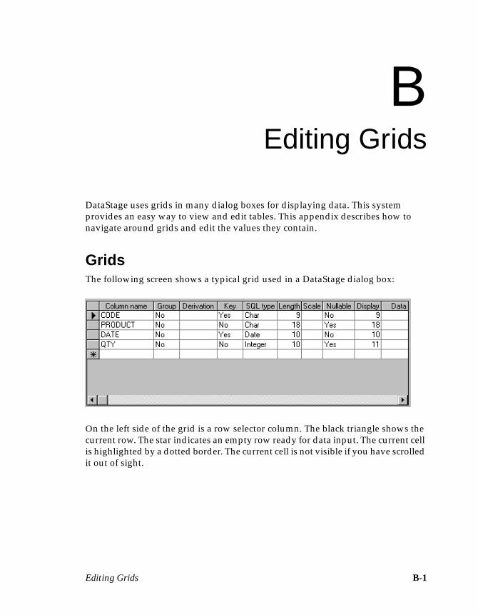
Editing Grids B-1
BEditing Grids
DataStage uses grids in many dialog boxes for displaying data. This systemprovides an easy way to view and edit tables. This appendix describes how tonavigate around grids and edit the values they contain.
GridsThe following screen shows a typical grid used in a DataStage dialog box:
On the left side of the grid is a row selector column. The black triangle shows thecurrent row. The star indicates an empty row ready for data input. The current cellis highlighted by a dotted border. The current cell is not visible if you have scrolledit out of sight.

B-2 DataStage Developer’s Guide
Navigating in the GridYou can move around the grid by using the mouse and scroll bars, or the keyboard.Table B-1 shows the keys that are used for navigation in the grid.
Table B-1. Keys Used in Grid Navigation
Key Action
Right Arrow Move to the next cell on the right.
Left Arrow Move to the next cell on the left.
Up Arrow Move to the cell immediately above.
Down Arrow Move to the cell immediately below.
Tab Move to the next cell on the right. If the current cell is in therightmost column, move forward to the next control on theform.
Shift-Tab Move to the next cell on the left. If the current cell is in theleftmost column, move back to the previous control on theform.
Page Up Scroll the page down.
Page Down Scroll the page up.
Home Move to the first cell in the current row.
End Move to the last cell in the current row.
Alt-Down Arrow In a drop-down list box, enter edit mode and move downthe list.
Editing Grids B-3
Editing in the GridYou can edit the contents of the current cell in three ways:
• Start typing in the cell.• Press the F2 key to put the cell into edit mode.• Choose the Edit cell… option from the shortcut menu.
When you start editing, the current cell highlight changes to an insertion point ora drop-down list box appears, as appropriate. Table B-2 shows the keys that areused for editing in the grid.
Table B-2. Keys Used in Grid Editing
Key Action
Esc Cancel the current edit. The grid leaves edit mode, and the cellreverts to its previous value. The focus does not move.
Enter Accept the current edit. The grid leaves edit mode, and the cellshows the new value. A pencil symbol appears in the rowselector column to indicate that the row has been modified.When the focus moves away from a modified row, the row isvalidated. If the data passes validation, the pencil icon isremoved; otherwise, a message box is displayed, and the focusreturns to the modified row.
Up Arrow Move the selection up a drop-down list or to the cell immedi-ately above.
Down Arrow Move the selection down a drop-down list or to the cell imme-diately below.
Left Arrow Move the insertion point to the left in the current value. Whenthe extreme left of the value is reached, exit edit mode andmove to the next cell on the left.
Right Arrow Move the insertion point to the right in the current value. Whenthe extreme right of the value is reached, exit edit mode andmove to the next cell on the right.
Ctrl-Enter Enter a line break in a value.
B-4 DataStage Developer’s Guide
Adding RowsYou can add a new row by entering data in the empty row indicated by the star.When you move the focus away from the row, the new data is validated. If it passesvalidation, it is added to the table, and a new empty row appears. Alternatively,press the Insert key or choose Insert row… from the shortcut menu, and a row isinserted with the default column name Newn, ready for you to edit (where n is aninteger providing a unique Newn column name).
Deleting RowsTo delete a row, click anywhere in the row you want to delete. The triangle movesto show that this is now the current row. Press the Delete key or choose Delete rowfrom the shortcut menu. To delete multiple rows, hold down the Ctrl key and clickin the row selector column for the rows you want to delete and press the Deletekey or choose Delete row from the shortcut menu.
Troubleshooting C-1
CTroubleshooting
This appendix describes problems you may encounter with DataStage and givessolutions.
Cannot Start DataStage ClientsCheck that UniVerse is actually running on the server.
On Windows NT servers, ensure that the UniVerse Resource service, UniVerse RPCservice, and UniVerse Telnet service are all started.
On UNIX servers, ensure that the RPC daemon (uvrpcd) is started.
Problems While Working with UniDataFor more information about connecting to UniData sources, see the technicalbulletin Accessing UniVerse and UniData Databases from DataStage (74-0121). This issupplied with the DataStage online documentation.
Connecting to UniData DatabasesWhen the DataStage 3.5 server is installed, a copy of the UniData API configura-tion file UNIAPI.INI is installed in the Windows directory. If, when you firstattempt to connect to your UniData server, you get an error message similar to:
UniData Client error: call to UniOpenPos returned 45 - Clientversion (11) and server version (12) are incompatible
then you must edit the UNIAPI.INI file and change the value of the PROTOCOLvariable. In this case, change it from 11 to 12:
PROTOCOL = 12
C-2 DataStage Developer’s Guide
Importing UniData MetadataWhen importing UniData metadata, note that the server name required in theDataStage Manager dialog box is the UniData server node name, not the Object-Call (UNIAPI.INI) file entry name.
If the UniData server is on the same node as the DataStage server, then the namelocalhost can be used.
Using the UniData StageThe UniData stage uses the UniData Basic ITYPE function to evaluate virtualattributes and this requires that the virtual attributes are compiled. If they are not,when the link is opened an error occurs which indicates the first uncompiled I-type/virtual attribute it finds. In this instance, the solution is to compile all of theI-types/virtual attributes, not just the first one reported in the error message.
There are certain verbs that need to be available for use on the UniData databasewhen the job containing the UniData stage is first run, or when the Data Browseris first used in the stage. These are:
• BASIC• CATALOG• NEWPCODE
The BP directory file must also be available.
After the initial job run or first use of the Data Browser, these can be removed ordisabled if required for security reasons.
Problems with the Documentation Tool
Installing the Documentation ToolYou should avoid trying to install the Documentation Tool in a directory withinsufficient disk space. If the install runs out of space, an error can occur whichremoves the Tahoma font from the system, and that can subsequently cause prob-lems with Microsoft Word. If this situation arises, the Tahoma font can be found inthe Documentation Tool install directory, from where you can reinstall it.
You should avoid running the setup program from within the Documentation Tooldirectory to remove or reinstall the tool. The operation will fail. Always use themain setup program on the DataStage CD.
Troubleshooting C-3
Using Plug-in ReportsThe report for a plug-in stage type does not include information as to whether thestage supports reference links.
Problems Running Jobs
Job Compiles Successfully but Will Not RunCheck that your job design does not have cyclic dependencies within a sequenceof active stages. This may cause your job to fail as one stage waits for another,which is in turn waiting for it.
Job from Previous DataStage Release Will Not RunIf you run a job created using an earlier DataStage release, you may get themessage:
Job has not been compiled with compatible compiler
The solution is to recompile, rerelease, and, if necessary, repackage jobs under thelater release of DataStage.
Miscellaneous Problems
Turning Grid Lines On and OffYou can turn Designer grid lines on and off from the Options dialog box, but,unlike the other options, this one does not take effect until the next time you startthe Designer.
Landscape PrintingYou cannot print in landscape mode from the DataStage Manager or Directorclients.
Browsing for DirectoriesWhen browsing directories within DataStage, you may find that only local driveletters are shown. If you want to use a remote drive letter, you should type it inrather than relying on the browse feature.

C-4 DataStage Developer’s Guide
Index-1
A
account nameHashed File stage 9-2UniData stage 8-2UniVerse stage 7-3
ActiveX (OLE) functions 4-43importing 4-43programming functions 16-3
addingContainer stages 5-28Plug-in stages 5-13stages 3-8, 5-12
after-job subroutines 2-4, 5-31after-load stored procedures 14-5, 14-7after-stage subroutines 2-4
for Aggregator stages 12-2for Plug-in stages 13-6for Transformer stages 11-5, 11-11
aggregating data 1-3using a UniVerse stage 7-13using an Aggregator stage 12-7using an ODBC stage 6-15using COUNT function 6-15, 7-14using SUM function 6-15, 7-14
AGGREGATOR Plug-in 12-9Aggregator stages 2-4, 5-11
editing 12-1input data to 12-3Inputs page 12-3output data from 12-5Outputs page 12-5sorting input data 12-4specifying after-stage
subroutines 12-2
specifying before-stagesubroutines 12-2
Stage page 12-2alternative projects 4-8assessing your data 4-1assigning data elements 3-6, 4-40associations 4-26Attach to Project dialog box 3-2, 4-2,
5-2
B
bad rows 15-6BASIC routines
before/after subroutines 16-8copying 16-15creating 16-8editing 16-15entering code 16-9name 16-5renaming 16-15saving code 16-9testing 16-11transform functions 16-8type 16-5version number 16-6viewing 16-15writing 16-1
BCP utility 14-1running from command line 14-1switches 14-1unsupported switches 14-2
BCPLoad Plug-indefinition 14-4stage properties 14-4
Index
Index-2 DataStage Developer’s Guide
BCPLoad stages 2-4, 14-1demo 14-10editing 14-6overview 14-1specifying job parameters 14-6stored procedures 14-7supported SQL data types 14-3table definitions 14-3using 14-5
before/after-subroutinesbuilt-in A-7creating 16-8
before-job subroutines 2-4, 5-31before-load stored procedures 14-5,
14-7before-stage subroutines 2-4
for Aggregator stages 12-2for Plug-in stages 13-6for Transformer stages 11-5, 11-11
breakpoints 17-1browsing server directories 5-22, C-3built-in
before/after-subroutines A-7data elements 2-4, 4-42routines A-7stages 5-11transforms 2-4
bulk copy API 14-1bulk copy program 14-1
C
changing the printer setup 18-9cleaning data values 15-2column definitions 2-4, 4-21
column name 4-22, 5-18, 12-4, 12-6data element 4-22, 5-18, 12-4, 12-6defining for a stage 5-18deleting 4-27, 4-37, 5-20editing 4-27, 4-36, 5-19
using the Columns grid 5-19using the Edit button 5-19
entering 4-25
inserting 5-19key fields 4-22, 5-18, 12-6length 4-22, 5-18, 12-4, 12-6loading 4-26, 5-21scale factor 4-22, 5-18, 12-4, 12-6
columnsrenaming by mapping 15-4renaming during Orabulk
stage 15-2Columns grid 4-21, 5-18commands, sqlldr 15-1, 15-4compiling
code in BASIC routines 16-10jobs 3-20, 17-1
connection type 6-2, 7-2UniVerse 7-2, 7-3
Container Input stage 5-12, 5-28Container Output stage 5-12, 5-28Container stages 2-4, 5-12, 5-28containers 2-4, 5-11, 5-27
creating 5-27editing 5-28viewing 5-28
converting values 15-2copying
BASIC routine definitions 16-15items in the Repository 4-8
creatingBASIC routines 16-8containers 5-27data elements 4-38data warehouses 1-2, 4-2executable jobs 17-1items in the Repository 4-6jobs 3-6, 5-8stored procedure definitions 4-34table definitions 4-24
CTLIB client library, installing 14-2current cell in grids B-1custom transforms 2-4
creating 11-14customizing the Tools menu 4-8
Index-3
D
dataaggregating 1-3extracting 1-3sources 2-6transforming 1-3
Data Browser 3-14, 4-28, 6-6, 6-11, 7-6,7-10, 8-4, 8-6, 9-4, 9-6, 10-5, 10-6
definition 2-5using 5-23
data elementsassigning 3-6, 4-40built-in 4-42creating 4-38defining 4-38editing 4-41viewing 4-41
data types, SQL Server 14-3data values
cleaning 15-2validating 15-2
data warehousesadvantages of 1-4creating 4-2example 3-1
DataStageclient components 2-1concepts 2-4jobs 2-2overview 2-1programming in 16-1projects 2-2server components 2-2terms 2-4
DataStage Administrator 2-2, 2-5DataStage Designer 2-1, 2-5, 5-1
exiting 5-10main window 5-3starting 5-1
DataStage Designer window 5-3menu bar 5-3
shortcut menus 5-7status bar 5-6tool palette 5-5toolbar 5-5
DataStage Director 2-2, 2-5DataStage Manager 2-2, 2-5, 4-2
exiting 4-10starting 3-2, 4-2using 4-2, 4-6
DataStage Manager window 3-3, 4-3display area 4-5menu bar 4-4project tree 4-5shortcut menus 4-6title bar 4-4toolbar 4-4
DataStage Package Installer 2-2, 2-5DataStage Repository 2-2, 2-6DataStage Server 2-2DBLIB client library, installing 14-2Debug Window 17-2debugger 17-1
toolbar 5-7, 17-5Define Sequential Metadata dialog
box 4-17defining
data elements 4-38data warehouses 1-3job parameters 5-33table definitions 3-4
deletingcolumn definitions 4-27, 4-37, 5-20items in the Repository 4-7job parameters 5-35links 5-17stages 5-14
demo, BCPLoad stage 14-10developing jobs 3-8, 5-1, 5-12Diagram window 5-4directory path
Hashed File stage 9-2Sequential File stage 10-2
Index-4 DataStage Developer’s Guide
display area in DataStage Managerwindow 4-5
documentation conventions xvDocumentation Tool 18-4
dialog box 18-5toolbar 18-5troubleshooting C-2
Documentation Tool dialog box 18-4Documentation Tool toolbar 18-5
E
edit mode in grids B-3editing
Aggregator stages 12-1BASIC routine definitions 16-15BCPLoad stage 14-6column definitions 4-27, 4-36, 5-19
using the Columns grid 5-19using the Edit button 5-19
containers 5-28data elements 4-41grids B-1, B-3job parameters 5-34job properties 5-30ODBC stages 6-1Plug-in stage properties 13-9Repository items 4-7stages 3-10, 5-17stored procedure definitions 4-36table definitions 4-27Transformer stages 11-6UniVerse stages 7-1
empty values 15-6entering
code in BASIC routines 16-9column definitions 4-25SQL statements 6-6, 6-11, 7-6, 7-9
environment variables 15-4equijoins 11-4error handling 19-6
errorsand BCPLoad stage 14-7and Orabulk stage 15-6and UniData stage C-1compilation 17-6
examplesof projects 3-1of reports 18-6of routines A-7of transform functions A-7
exitingDataStage Designer 5-10DataStage Manager 4-10
Export option, using 19-3exporting
from the Manager 19-3job components 19-3jobs 19-3
Expression Editor 2-5, 5-36, 5-41, 11-12configuring 5-41
external ActiveX (OLE) functions 4-43extracting data 1-3
F
file formats for Sequential Filestages 10-4, 10-6
file namein Hashed File stage 9-3, 9-5in Sequential File stage 10-3, 10-6in UniData stage 8-4, 8-5
filesBCPLoad demo 14-10job log 14-7loading into Oracle 15-4log 15-5
FROM clause 6-12, 7-10
Index-5
G
generated queriesfor ODBC input data 6-6for ODBC output data 6-11for UniVerse input data 7-6for UniVerse output data 7-10
grids B-1, C-3adding rows in B-4current cell B-1deleting rows in B-4editing B-1, B-3, C-3keys used for navigating in B-2keys used in editing B-3navigating in B-2row selector column B-1
GROUP BY clause 6-12, 7-11using 6-15, 7-14
H
Hashed File stages 2-5, 5-11account name for 9-2input data to 9-3Inputs page 9-3output data from 9-5Outputs page 9-5specifying a file name for 9-3, 9-5specifying the directory path 9-2Stage page 9-2update action 9-4
hashed files, importing metadatafrom 4-13
HAVING clause 6-12, 7-11using 6-14, 7-12
I
Import option, using 19-1importing
external ActiveX (OLE)functions 4-43
into the Manager 19-1job components 19-1jobs 19-1metadata
from a Sybase databasetable 14-3
from an SQL Server databasetable 14-3
stored procedure definitions 4-31table definitions 3-4, 4-10
from a hashed file 4-13from a sequential file 4-16from a UniData file 4-14from a UniVerse table 4-12from an ODBC data source 4-10
input datato Aggregator stages 12-3to Hashed File stages 9-3to ODBC stages 6-4to Plug-in stages 13-7to Sequential File stages 10-2to UniData stages 8-3to UniVerse stages 7-4
input links 11-4input parameters, specifying 4-35inserting column definitions 5-19installing
CTLIB client library 14-2DBLIB client library 14-2NetLIB client library 14-2Plug-ins 13-4SQL Server client software 14-2
integrity constraints 15-2
J
job control routines 2-5, 5-37Job Details window 5-6job parameters 5-32
BCPLoad stages 14-6defining 5-33deleting 5-35

Index-6 DataStage Developer’s Guide
editing 5-34using 5-35
job properties 5-30editing 5-30saving 5-32viewing 5-30
jobscompiling 3-20, 17-1creating 3-6, 5-8developing 3-8, 5-1, 5-12opening 5-9overview 2-2packaging 19-6properties of 5-30running 3-21saving 5-8version number 5-30
K
key field 4-22, 4-33, 5-18, 6-11, 7-10,12-6
L
line terminators 10-2linking stages 3-9, 5-15, 5-16links
deleting 5-17input 11-4moving 5-16multiple 5-17output 11-4reject 11-4renaming 5-17
loadingcolumn definitions 4-26, 5-21files into Oracle 15-4
log file 15-5
M
manually enteringstored procedure definitions 4-34table definitions 4-24
menu barin DataStage Designer window 5-3in DataStage Manager window 4-4
metadatadefinition 2-5importing for a BCPLoad
stage 14-3Microsoft SQL Server 14-1moving
links 5-16stages 5-14
multiple links 5-17multivalued data 4-21, 5-19
N
Name Editor 5-4navigation in grids B-2NetLIB client library
configuring 14-2installing 14-2
normalization 5-24definition 2-5
null values 4-22, 4-34, 5-18, 12-4, 12-6,15-6
O
ODBC stages 2-6, 5-11connection type for 6-2editing 6-1entering SQL statements in 6-6input data to 6-4
using a generated query 6-6using a stored procedure 6-8using a user-defined SQL
statement 6-7

Index-7
Inputs page 6-4output data from 6-9
using a generated query 6-11using a stored procedure 6-17using a user-defined SQL
statement 6-16Outputs page 6-9procedure name for 6-5Stage page 6-2stored procedure parameters 6-11table name for 6-4, 6-9update action for 6-5viewing SQL statements in 6-6,
6-10opening a job 5-9Orabulk stages 2-6
environment variables 15-4errors 15-6properties 15-3
Oraclebin subdirectory 15-4loading files into 15-4sqlldr command 15-1
ORDER BY clause 6-12, 7-11using 6-14, 7-13
output datafrom Aggregator stages 12-5from Hashed File stages 9-5from ODBC stages 6-9from Plug-in stages 13-8from Sequential File stages 10-5from UniData stages 8-4
output links 11-4overview
of BCPLoad stage 14-1of DataStage 2-1of jobs 2-2of projects 2-2of Transformer stage 11-1
P
Packager Wizard, using 19-6packaging
jobs 19-6Plug-ins 13-4, 19-6
parameter definitionsdata element 4-34key fields 4-33length 4-33scale factor 4-33
Parameters grid 4-33Parameters page, ODBC stages 6-11Plug-in stages 2-6, 5-12
adding 5-13BCPLoad 14-1editing properties 13-9Inputs page 13-7Orabulk 15-1output data 13-8output link properties for 13-8Outputs page 13-8properties for 13-5specifying after-stage
subroutines 13-6specifying before-stage
subroutines 13-6specifying input data 13-7specifying input properties
for 13-7Stage page 13-5
Plug-ins 2-6, 13-1BCPLoad 13-1installing 13-4Orabulk 13-1packaging 13-4, 19-6registering 13-2using 13-4
printer setup 18-9

Index-8 DataStage Developer’s Guide
printingDocumentation Tool dialog
box 18-4example of reports 18-6from the Designer 18-1, 18-9landscape C-3
procedure name 6-5programming in DataStage 16-1project tree 4-5projects
choosing alternative 4-8example 3-1overview 2-2setting up 3-2, 4-1
propertiesediting in Plug-in stages 13-9Plug-in 13-5Plug-in stages 13-7, 13-8
R
reference links 5-15registering Plug-in definitions 13-2reject links 11-4renaming
BASIC routines 16-15columns 15-2, 15-4items in the Repository 4-6links 5-17stages 5-14
replacing text in routine code 16-14reporting
generating reports 18-2Reporting Assistant dialog
box 18-1Reporting Tool 18-1
Reporting Assistant dialog box 18-1Reporting Tool 18-1Repository 2-2, 2-6Repository items
copying 4-8creating 4-6
deleting 4-7editing 4-7renaming 4-6viewing 4-7
Routine dialog box 16-5Code page 16-7Creator page 16-6General page 16-5using Find 16-12using Replace 16-12
routine name 16-5routines
built-in before/after-subroutines A-7
examples A-7writing 16-1
row selector column B-1rows, bad 15-6running a job 3-21
S
savingcode in BASIC routines 16-9job properties 5-32jobs 5-8
SELECT clause 6-12, 7-10Sequential File stages 2-6, 5-12
file formats for 10-4, 10-6input data 10-2Inputs page 10-2output data 10-5Outputs page 10-5specifying a file name for 10-3, 10-6specifying line terminators 10-2specifying the directory path
for 10-2Stage page 10-2
sequential files, importing metadatafrom 4-16
Server 2-2server directories, browsing 5-22
Index-9
setting file formats 10-4, 10-6setting up a project 3-2, 4-1shortcut menus
in DataStage Designer window 5-7in DataStage Manager window 4-6in Transformer Editor 11-3
source, definition 2-6specifying input parameters for stored
procedures 4-35SQL
data precision 4-22, 4-33, 5-18, 12-4,12-6
data scale factor 4-22, 4-33, 5-18,12-4, 12-6
data type 4-22, 4-33, 5-18, 12-4, 12-6display characters 4-22, 4-34, 5-18,
12-4, 12-6SQL Server
supported data types 14-3unsupported BCP switches 14-2unsupported data types 14-3
SQL statementsentering 6-6, 7-6syntax 6-11, 7-10viewing 6-6, 6-10, 7-6, 7-9
sqlldr command 15-4log file 15-5running under UNIX 15-5specifying the control file 15-3specifying the data file 15-3
stage propertiesBCPLoad 14-4Orabulk 15-3
stages 2-6, 5-11adding 3-8, 5-12Aggregator 2-4, 5-11BCPLoad 2-4built-in 5-11column definitions for 5-18Container 2-4, 5-12Container Input 5-12Container Output 5-12
deleting 5-14editing 3-10, 5-17
Aggregator 12-1BCPLoad 14-6Hashed File 9-1ODBC 6-1Orabulk 15-1Plug-in 13-5Sequential File 10-1Transformer 11-1UniData 8-1UniVerse 7-1
Hashed File 2-5, 5-11linking 3-9
links 5-15moving 5-14ODBC 2-6, 5-11Orabulk 2-6, 15-1Plug-in 2-6, 5-12renaming 5-14Sequential File 2-6, 5-12specifying 5-12Transformer 2-4, 2-6, 5-12UniData 2-6, 5-12UniVerse 2-7
startingDataStage Designer 5-1DataStage Manager 3-2, 4-2
status bar in DataStage Designerwindow 5-6
stored procedure definitions 4-29, 5-24creating 4-34editing 4-36importing 4-31manually defining 4-34result set 4-35viewing 4-36
stored procedures 4-30for ODBC input data 6-8for ODBC output data 6-17input parameters 6-11using in a BCPLoad stage 14-7

Index-10 DataStage Developer’s Guide
stream link 5-15supported BCP switches 14-4supported data types
SQL Server 14-3Sybase Server 14-3
Sybase Server 14-1supported data types 14-3unsupported BCP switches 14-2unsupported data types 14-3
T
Table Definition dialog box 4-20for stored procedures 4-32Parameters page 4-33
table definitions 2-6, 4-10, 14-3column definitions 4-21creating 4-24defining 3-4editing 4-27importing 3-4, 4-10manually entering 4-24viewing 4-27
table name 6-4, 7-4terms and concepts 2-4testing BASIC routines 16-11title bar in DataStage Manager
window 4-4tool palette 5-5toolbars
debugger 5-7, 17-5Designer 5-5Documentation Tool 18-5Manager 4-4Transformer Editor 11-2
transform functionscreating 16-8examples A-7
Transformer Editor 2-6, 11-1links 11-2shortcut menus 11-3toolbar 11-2
Transformer stages 2-4, 2-6, 5-12, 11-1basic concepts 11-4editing 11-6Expression Editor 11-12specifying after-stage
subroutines 11-11specifying before-stage
subroutines 11-11transforms 11-14
transforming data 1-3transforms 2-6
custom 2-4in Transformer stage 11-14
troubleshooting C-1compilation errors 17-6
troubleshooting compilationerrors 17-6
U
UniData stages 2-6, 5-12account name for 8-2Inputs page 8-3output data from 8-4Outputs page 8-4specifying a file name for 8-4, 8-5Stage page 8-2troubleshooting C-1update action 8-4
UniVerse stages 2-7, 5-11, 7-1account name for 7-3and UniVerse connection 7-2, 7-3connection type for 7-2editing 7-1entering SQL statements in 7-6input data to 7-4
using a generated query 7-6using a user-defined SQL
statement 7-7output data from
using a generated query 7-10using a user-defined SQL
statement 7-14
Index-11
Stage page 7-2table name for 7-4, 7-8update action for 7-5viewing SQL statements in 7-6, 7-9
UNIX line terminators 10-2unsupported BCP switches
SQL Server 14-2Sybase Server 14-2
unsupported data typesSQL Server 14-3Sybase Server 14-3
update actionin Hashed File stages 9-4in ODBC stages 6-5in UniData stages 8-4in UniVerse stages 7-5
user-defined SQL queries 6-11, 7-9user-defined SQL statements
for ODBC input data 6-7for ODBC output data 6-16for UniVerse input data 7-7for UniVerse output data 7-14
usingBCPLoad stage 14-5Container Input stage 5-28Container Output stage 5-28COUNT function 6-15, 7-14Data Browser 5-23DataStage Manager 4-2, 4-6Export option 19-3generated queries
for ODBC input data 6-6for ODBC output data 6-11for UniVerse input data 7-6for UniVerse output data 7-10
GROUP BY clauses 6-15, 7-14HAVING clauses 6-14, 7-12Import option 19-1job parameters 5-35Packager Wizard 19-6Plug-ins 13-4Print from the Designer 18-9
stored proceduresfor ODBC input data 6-8for ODBC output data 6-17in BCPLoad stages 14-7
SUM function 6-15, 7-14user-defined SQL statements
for ODBC input data 6-7for ODBC output data 6-16for UniVerse input data 7-7for UniVerse output data 7-14
WHERE clauses 6-13, 7-12
V
validating data values 15-2values
converting 15-2empty 15-6null 15-6
version numberfor a BASIC routine 16-6for a job 5-30
viewingBASIC routine definitions 16-15containers 5-28data elements 4-41job properties 5-30Repository items 4-7SQL statements 6-6, 6-10, 7-6, 7-9stored procedure definitions 4-36table definitions 4-27
W
WHERE clause 6-12, 7-11using 6-13, 7-12
Windows NT line terminators 10-2writing BASIC routines 16-1

Index-12 DataStage Developer’s Guide
To help us provide you with the best documentation possible, please makeyour comments and suggestions concerning this manual on this form and faxit to us at 508-366-3669, attention Technical Publications Manager. Allcomments and suggestions become the property of Ardent Software, Inc. Wegreatly appreciate your comments.
Comments
Name: ________________________________________ Date:_________________
Position: ______________________________________ Dept:_________________
Organization:__________________________________ Phone:________________
Address: ____________________________________________________________
____________________________________________________________________
Name of Manual: DataStage Developer’s Guide
Part Number: 76-1000-DS3.5