Embed Size (px)
Citation preview

Interrupted Boriding of Medium-Carbon Steels
P. GOPALAKRISHNAN, P. SHANKAR, M. PALANIAPPA, and S.S. RAMAKRISHNAN
The results of an extensive study on the microstructure, microhardness, corrosion, and tensile propertiesof continuously borided and interrupted borided specimens of medium-carbon steel are compared.Carbon repartitioning away from the surface is one of the principal modes to accommodate the highstrains introduced on boron diffusion into the case. However, this is a kinetically constrained processand is more predominant on interrupted boriding. The effect of such a carbon redistribution is toresult in microstructural modifications including (1) blunting of boride needle tips, (2) precipitationof nearly spherical and fine borocarbides, and (3) enhanced carbon segregation at the boride needle/steel matrix interface on interrupted boriding. The mechanisms aiding the change in the morphologyof the boride needles are discussed. The improvements in the mechanical and corrosion propertiesof the interrupted borided specimens over continuously borided specimens are described.
I. INTRODUCTION of boron carbide and borax mixtures.[5,6] Alternatively, boroncarbide or amorphous boron has been used as the boronTHE surfaces of engineering components are subjectedsource, along with diluents such as silicon carbide or aluminato higher stresses and greater fatigue, abrasion, and corrosiveor graphite and activators like KBF4 or NaF in the boridingdamages than the interior. Therefore, more than 90 pct ofmixtures.[4,6,8–10] Ferroboron can be considered as a boronthe service failures of engineering components initiate at,source instead of boron carbide. However, it is reported thator near, the surface. Surface modification techniques arethe commercial grades of ferroboron contain impurities likeemployed to improve the resistance to failure by producingSi and Al; therefore, the use of this material leads to aa hard and wear-resistant case around a soft and tough core.degenerate layer. However, special-quality ferroboron canTwo major classes of treatments available for enhancing thebe used to get a good-quality boride case, according to thesurface properties are thermal and thermochemical. Thermalclassical review book by Von Matuschka,[11] which is atreatments, such as flame and induction hardening, modifycomprehensive, general, and theoretical compendium onthe microstructure without modifying the surface chemistry,boriding.whereas in thermochemical methods, the surface chemistry
The molten salt boriding process is usually performedis altered. Carburizing and nitriding are well known thermo-using anhydrous borax, mixed with reducing agents likechemical methods.[1] Boriding or boronizing is a recentboron carbide, silicon carbide, or silico-calcium.[12] Amor-process, which is analogous to carburizing and nitriding.phous boron is stated to be better than boron carbide, sinceBoriding can develop surface hardness in the range ofit produces less slurry.[13] Electrolytic boriding is carried out1500 to 2000 HV, as compared to a hardness in the rangein inert atmospheres like argon, using borax-based melts atof 600 to 1100 HV for nitriding, 700 to 850 HV for carburiz-about 1173 K at a current density of about 0.15 to 0.25 A/ing, and 950 to 1100 HV for chromium plating. Boridedcm2.[14,15,16] Electrolytic boriding produces thicker coatingslayers provide a wear resistance comparable to that of sint-in relatively shorter times compared to molten salt or packered carbides. The wear resistance of cold-working tools isboriding processes.[16] There are many other techniques forincreased by about 10 times and that of hot-working toolsboriding, e.g., gas boriding, vacuum boriding, plasma borid-and dies by about 3 times as a result of boriding.[2] If theing, and thermal spraying of powders.[2,12,17] Out of all theseprocess has been performed properly and the right materialtechniques, pack and molten salt (electroless) processes areand layer thickness have been chosen, boriding can extendtechnologically simpler and more economical compared tothe service life of engineering components beyond thatother boriding processes.imparted by traditional methods like carburizing or
During boriding of plain-carbon steels, needle-like FeBnitriding.[3,4]
and Fe2B phases are formed. When the boron potential isVarious processes adopted for boriding include pack bor-low, Fe2B phase alone forms in the case. At higher potentialsiding, molten salt boriding, electrolytic boriding, gas borid-of boron, FeB phase also forms along with Fe2B. The Fe2Bing, vacuum boriding, etc. In pack boriding, the sample isphase forms adjacent to the core and the FeB phase formscleaned and kept surrounded by solid mixtures consistingnear the surface.[4,10,12,18] It is reported that FeB19 phase alsoforms,[19] very rarely, when the boron potential is very high.A single-phase structure is desirable.[6] Fe2B is preferred to
P. GOPALAKRISHNAN, Assistant Professor, Department of Metallurgi- FeB,[10,20,21] since FeB is very hard and brittle and has acal Engineering, and S.S. RAMAKRISHNAN, Dean, School of Metallurgy coefficient of thermal expansion that differs from the matrixand Materials, and Professor, Department of Metallurgical Engineering,
by a factor of 3 and that causes spalling during cooling.[22]are with PSG College of Technology, Coimbatore 641 004, India. P.SHANKAR, Scientist, is with the Metallurgy and Materials Group, Indira Although boriding of plain-carbon steels improves theGandhi Centre for Atomic Research, Kalpakkam 603 102, India. M. wear, abrasion, fatigue, tensile, corrosion, corrosion-fatigue,PALANIAPPA, formerly ME Student, Department of Metallurgical Engi- and oxidation properties,[1,5,6,8,13,14,23,24] one serious draw-neering, PSG College of Technology, is Doctoral Scholar, Indian Institute
back is the brittleness of the case.[6,23] Several methods haveof Technology, Madras 600036, India.Manuscript submitted September 25, 2000. been attempted to solve this problem. They include (1) partial
METALLURGICAL AND MATERIALS TRANSACTIONS A VOLUME 33A, MAY 2002—1475
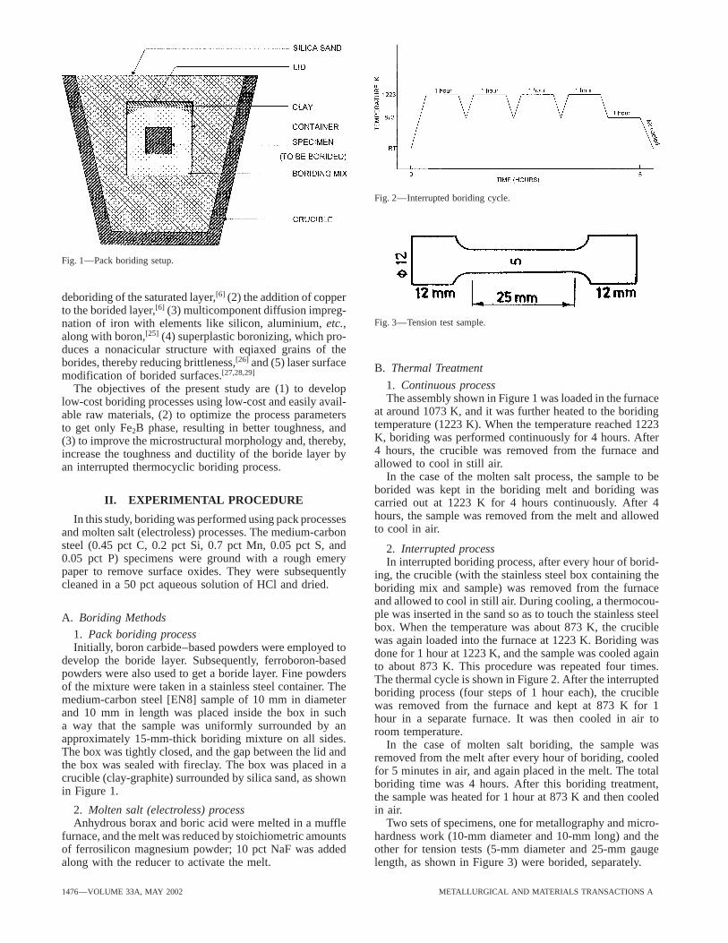
Fig. 2—Interrupted boriding cycle.
Fig. 1—Pack boriding setup.
deboriding of the saturated layer,[6] (2) the addition of copperto the borided layer,[6] (3) multicomponent diffusion impreg-
Fig. 3—Tension test sample.nation of iron with elements like silicon, aluminium, etc.,along with boron,[25] (4) superplastic boronizing, which pro-duces a nonacicular structure with eqiaxed grains of theborides, thereby reducing brittleness,[26] and (5) laser surface B. Thermal Treatmentmodification of borided surfaces.[27,28,29]
1. Continuous processThe objectives of the present study are (1) to developThe assembly shown in Figure 1 was loaded in the furnacelow-cost boriding processes using low-cost and easily avail-
at around 1073 K, and it was further heated to the boridingable raw materials, (2) to optimize the process parameterstemperature (1223 K). When the temperature reached 1223to get only Fe2B phase, resulting in better toughness, andK, boriding was performed continuously for 4 hours. After(3) to improve the microstructural morphology and, thereby,4 hours, the crucible was removed from the furnace andincrease the toughness and ductility of the boride layer byallowed to cool in still air.an interrupted thermocyclic boriding process.
In the case of the molten salt process, the sample to beborided was kept in the boriding melt and boriding was
II. EXPERIMENTAL PROCEDURE carried out at 1223 K for 4 hours continuously. After 4hours, the sample was removed from the melt and allowedIn this study, boriding was performed using pack processesto cool in air.and molten salt (electroless) processes. The medium-carbon
steel (0.45 pct C, 0.2 pct Si, 0.7 pct Mn, 0.05 pct S, and 2. Interrupted process0.05 pct P) specimens were ground with a rough emery In interrupted boriding process, after every hour of borid-paper to remove surface oxides. They were subsequently ing, the crucible (with the stainless steel box containing thecleaned in a 50 pct aqueous solution of HCl and dried. boriding mix and sample) was removed from the furnace
and allowed to cool in still air. During cooling, a thermocou-ple was inserted in the sand so as to touch the stainless steelA. Boriding Methodsbox. When the temperature was about 873 K, the crucible
1. Pack boriding process was again loaded into the furnace at 1223 K. Boriding wasInitially, boron carbide–based powders were employed to done for 1 hour at 1223 K, and the sample was cooled again
develop the boride layer. Subsequently, ferroboron-based to about 873 K. This procedure was repeated four times.powders were also used to get a boride layer. Fine powders The thermal cycle is shown in Figure 2. After the interruptedof the mixture were taken in a stainless steel container. The boriding process (four steps of 1 hour each), the cruciblemedium-carbon steel [EN8] sample of 10 mm in diameter was removed from the furnace and kept at 873 K for 1and 10 mm in length was placed inside the box in such hour in a separate furnace. It was then cooled in air toa way that the sample was uniformly surrounded by an room temperature.approximately 15-mm-thick boriding mixture on all sides. In the case of molten salt boriding, the sample wasThe box was tightly closed, and the gap between the lid and removed from the melt after every hour of boriding, cooledthe box was sealed with fireclay. The box was placed in a for 5 minutes in air, and again placed in the melt. The totalcrucible (clay-graphite) surrounded by silica sand, as shown boriding time was 4 hours. After this boriding treatment,in Figure 1. the sample was heated for 1 hour at 873 K and then cooled
in air.2. Molten salt (electroless) processAnhydrous borax and boric acid were melted in a muffle Two sets of specimens, one for metallography and micro-
hardness work (10-mm diameter and 10-mm long) and thefurnace, and the melt was reduced by stoichiometric amountsof ferrosilicon magnesium powder; 10 pct NaF was added other for tension tests (5-mm diameter and 25-mm gauge
length, as shown in Figure 3) were borided, separately.along with the reducer to activate the melt.
1476—VOLUME 33A, MAY 2002 METALLURGICAL AND MATERIALS TRANSACTIONS A

C. Microscopic Observations
One flat end of the borided specimens was ground gentlyto remove the boride layer. Then, the samples were mountedin cold mounting material and prepared for metallographicstudy using various grades of emery papers. Final polishingwas performed using diamond paste, and etching was carriedout using equal quantities of nital and picral. The microstruc-ture of the borided samples was studied and photographedusing a Nikon-Epiphot optical metallograph. The metallo-graphially polished specimens, as well as the fractured
Fig. 4—Schematic arrangement of Falex tester for evaluating scuffingsurfaces of the tension test specimens, were also observedresistance of materials. (a) Key components of instrument. (b) Explodedusing a JEOL* JSM T100 scanning electron microscope atview showing arrangement of V-blocks and rotating journal.
*JEOL is a trademark of Japan Electron Optics Ltd., Tokyo.
suitable magnifications. 2. Faville Levally testThe Faville Levally (Falex) test machine, shown in Figure
4, is a special wear-testing machine used for the evaluationD. Analysis by X-ray Diffraction of the scuffing or scoring resistance of the case-hardened
samples. In this test, a specimen of 40 mm in length andSpecimens borided by the various processes were ana-6.5 mm in diameter was attached to the collet by means oflyzed using a PHILIPS* X-ray diffractometer with coppera cotter pin, and the collet was attached to the main drive
*PHILIPS is a trademark of Philips Electronic Instruments Corp., Mah- shaft. Two jaws made of EN 45 (AISI 1038) steel, with awah, NJ. hardness of 24(61) HRC and having a 90-deg V-notch, fit
into the holes of the loading arm. During the test, these jawsKa radiation, X-ray diffraction and the (XRD) resultswere clamped around the rotating testpiece using the ratchetwere compared.wheel, and an initial load of 2000 N was applied to thespecimen. A load cell attached to one of the loading armssenses the applied load. For each test, a new pair of jawsE. Microhardness Measurementswas used. The main shaft holding the specimen was rotatedat a constant speed of 290 rpm by a motor. The load onMicrohardness measurements were carried out at 50 g loadthe specimen was increased continuously through a ratchetusing a Mitutoyo microhardness tester. The cross sectionwheel attached to a cam fitted to the shaft. The rate ofhardness profiles were measured on at least three locationsloading was maintained at approximately 100 Ns21. Thealong the case, and the average value was taken.tangential load was directly measured by means of anotherload cell. The Falex machine was interfaced with a computer,
F. Tension Test which continuously monitored the normal load and tangen-tial load during the test. The coefficient-of-friction values
The tensile strength and toughness were measured using were calculated from these data. The test was stopped at thea Zwick universal testing machine of 20-ton capacity. The onset of scuffing/scoring, which was indicated by a sharpspecimens subjected to interrupted boriding were compared increase in the frictional value. This is considered the end-with specimens subjected to continuous boriding. Also, spec- point of the test. In the worst case, the specimen may getimens subjected to the same heating cycles (as continuous welded to the jaws, or the specimen may extrude after reach-and interrupted boriding) in a protective atmosphere, but ing the red-hot condition, indicating poor stiffness. Whenwithout boriding, were also tested for purposes of compari- the specimen has the ability to resist scuffing, the specimenson. The strength and ductility were measured from the gets polished and the V-notches turn into a U-shape, indicat-stress-strain curves, and the toughness was measured by ing good scuffing resistance.calculating the area under the curve.
H. Corrosion TestingG. Wear Tests A copper chloride accelerated salt-spray corrosion test
(also termed the CASS test) was chosen to study the corro-1. Pin-on-disc—adhesive wear testWear tests were performed using a pin-on-disc machine sion behavior of the steels. This system should normally
employ a salt-spray chamber, but an immersion technique(Ducom TR20) under unlubricated dry sliding conditions.The disc material was EN24 steel in the hardened condition was used as an approximation. 2.6 g of cupric chloride in
one liter of glacial acetic acid was mixed thoroughly in a(65 HRC). The surface roughness of the disc is of finemachined quality. Both the unborided and borided specimens beaker, and the treated and untreated samples were subjected
to the corrosion test for a period of 64 hours. After 64 hours,were tested. During the test, the ambient temperature was303 K. The speed of the disc was 0.6 m/s. The duration of the samples were washed in running water and acetone and
then dried. The loss in weight of the treated sample and thethe test was 2.5 hours for each specimen. The ‘Z’ displace-ment of the pin under test was monitored using a precision untreated sample were measured using a chemical balance,
and the corrosion rate in mg/dm2/day was calculated forlinear variable differential transformer, and the wear lossesof the borided and unborided specimens were compared. both the treated and untreated samples.
METALLURGICAL AND MATERIALS TRANSACTIONS A VOLUME 33A, MAY 2002—1477
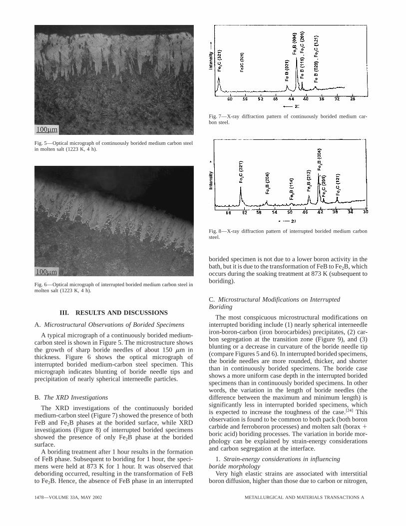
Fig. 7—X-ray diffraction pattern of continuously borided medium car-bon steel.
Fig. 5—Optical micrograph of continuously borided medium carbon steelin molten salt (1223 K, 4 h).
Fig. 8—X-ray diffraction pattern of interrupted borided medium carbonsteel.
borided specimen is not due to a lower boron activity in thebath, but it is due to the transformation of FeB to Fe2B, whichoccurs during the soaking treatment at 873 K (subsequent toboriding).
Fig. 6—Optical micrograph of interrupted borided medium carbon steel inmolten salt (1223 K, 4 h).
C. Microstructural Modifications on InterruptedBoriding
III. RESULTS AND DISCUSSIONSThe most conspicuous microstructural modifications on
interrupted boriding include (1) nearly spherical interneedleA. Microstructural Observations of Borided Specimensiron-boron-carbon (iron borocarbides) precipitates, (2) car-A typical micrograph of a continuously borided medium-bon segregation at the transition zone (Figure 9), and (3)carbon steel is shown in Figure 5. The microstructure showsblunting or a decrease in curvature of the boride needle tipthe growth of sharp boride needles of about 150 mm in(compare Figures 5 and 6). In interrupted borided specimens,thickness. Figure 6 shows the optical micrograph ofthe boride needles are more rounded, thicker, and shorterinterrupted borided medium-carbon steel specimen. Thisthan in continuously borided specimens. The boride casemicrograph indicates blunting of boride needle tips andshows a more uniform case depth in the interrupted boridedprecipitation of nearly spherical interneedle particles.specimens than in continuously borided specimens. In otherwords, the variation in the length of boride needles (thedifference between the maximum and minimum length) isB. The XRD Investigationssignificantly less in interrupted borided specimens, whichThe XRD investigations of the continuously boridedis expected to increase the toughness of the case.[24] Thismedium-carbon steel (Figure 7) showed the presence of bothobservation is found to be common to both pack (both boronFeB and Fe2B phases at the borided surface, while XRDcarbide and ferroboron processes) and molten salt (borax 1investigations (Figure 8) of interrupted borided specimensboric acid) boriding processes. The variation in boride mor-showed the presence of only Fe2B phase at the boridedphology can be explained by strain-energy considerationssurface.and carbon segregation at the interface.A boriding treatment after 1 hour results in the formation
of FeB phase. Subsequent to boriding for 1 hour, the speci- 1. Strain-energy considerations in influencingboride morphologymens were held at 873 K for 1 hour. It was observed that
deboriding occurred, resulting in the transformation of FeB Very high elastic strains are associated with interstitialboron diffusion, higher than those due to carbon or nitrogen,to Fe2B. Hence, the absence of FeB phase in an interrupted
1478—VOLUME 33A, MAY 2002 METALLURGICAL AND MATERIALS TRANSACTIONS A

Fig. 10—Optical micrograph of continuously borided medium carbon steelin pack process (1223 K, 4 h).
Fig. 9—Optical micrograph of borided low carbon steel showing carbonsegregation in the transition zone.
as the radius of the boron atom (0.097 nm) is much higherthan that of carbon (0.077 nm) or nitrogen (0.071 nm). Theshape of the second phase (precipitating phase) is generallygoverned by the balance between (1) the interfacial energy,
Fig. 11—Optical micrograph of interrupted borided medium carbon steelwhich is proportional to the interfacial area at the interface in pack process (1223 K, 4 h).between the two phases, and (2) the volume strain energy andchemical free-energy change, which are both proportional tothe volume of the new phase created. If the interfacial-energy
resulting in more rounded needle tips and thicker borideconsideration is the dominant factor, the most preferredneedles.shape is the spherical shape, as it is the shape which has
the minimum total interfacial energy. This is because the 2. Carbon redistribution on interrupted boridingIn the transition zone (zone next to the boride layer) inspherical shape has the least surface area per unit volume,
the disc shape has the highest area, and the rod or needle medium-carbon steels, the microstructure shows a differencebetween the interrupted and continuously borided speci-shape is in between. Thus, the disc shape would be the least
likely, and the rod shape would be more likely to form mens. The ratio of pearlite to ferrite is higher in the transitionzone in interrupted borided specimens, as compared to thethan the disc shape, based on the interfacial-energy criterion
alone. However, if strain energy is the dominating factor, a continuously borided specimens (Figures 10 and 11). Thisindicates that carbon segregates more in the transition zoneminimum strain energy would result in a disc or plate shape
and a maximum strain energy would result in a spherical below the boride layer in the interrupted borided specimensthan in the continuously borided specimens. It is well knownshape, and the rod shape would be in between. In the case
of the iron boride–iron interface, a needle- or rod-shaped that the solubility of carbon in iron borides is very low, andthe diffusion of boron into the matrix can result in significantgrowth results, possibly as an optimum compromise, because
both the strain-energy factor and the surface-energy factor strains, as mentioned previously. Redistribution of carbonatoms into boron-free regions at the interface of the advanc-are active to significant extents.
The curvature of the advancing tip of the boride needle ing tip could be a significant strain-accommodating mecha-nism during boriding. However, carbon redistribution ismay be considered to be determined by strain-energy consid-
erations. In the case of continuous boriding, the strains are obviously a kinetically limited phenomenon. During contin-uous boriding, kinetic factors limit any long-range redistribu-likely to be very high, resulting in sharp needles (with very
high curvature). On the other hand, in interrupted boriding, tion of carbon atoms. But, on interrupted boriding, asignificant carbon redistribution can take place during thestrain-accommodating mechanisms operate due to the ther-
mal cycling, and, as a consequence, the tip curvature reduces, cooling cycles when the temperatures are about 873 to 973 K.
METALLURGICAL AND MATERIALS TRANSACTIONS A VOLUME 33A, MAY 2002—1479

Fig. 12—Scanning electron micrograph of continuously borided medium Fig. 13—Scanning electron micrograph of interrupted borided mediumcarbon steel in pack process (1223 K, 4 h). carbon steel in pack process (1223 K, 4 h).
al.[32] and Qian and Stone.[19] As the carbon content in theThe diffusivity of carbon in alpha iron and in austenitetransition zone in interrupted borided specimens is higherare governed by the following relations:[30]
than in continuously borided specimens, the advancementDa
c 5 0.2 3 exp (220,100/RT ) [1] of boron perpendicular to the surface into the specimen isslowed down, acicular growth of the boride needles isDg
c 5 0.25 3 exp (234,500/RT ) [2]retarded, and lateral growth is promoted. Therefore, instead
The diffusivity values of boron in a -iron and in g -iron is of long thin needles, thicker and more rounded needles form.given by the relations[31]
3. Precipitation of borocarbidesDa
B 5 106 3 exp (262,000/RT ) [3] Another significant observation on interrupted boriding ofmedium-carbon steel is the precipitation of new interneedleDg
B 5 2 3 1023 3 exp (221,000/RT ) [4]particles in the interrupted boriding process. The particlesseen in the optical micrographs of interrupted boridedFrom Eqs. [1] and [2], it can be computed that the diffusiv-
ity of carbon in austenite at 1223 K is 1.71 3 1027 cm2/s and medium-carbon steel specimens are absent in continuouslyborided medium-carbon steel specimens. These precipitatesthat in ferrite at 873 K is 1.856 3 1026 cm2/s, respectively. In
contrast, the diffusivity of boron in austenite at 1223 K is are likely to be iron borocarbides, as suggested by Brakmanet al.[32] The hardness of these particles is in the range of3.53 3 1027 cm2/s and that in ferrite at 873 K is 3 3 10210
cm2/s. Carbon diffuses faster in alpha iron than in austenite, 1000 HV under a load of 25 g, as is expected for ironborocarbides. Koifman et al.[33] also has reported that short-whereas boron diffuses nearly 1000 times faster in austenite
than in ferrtite. The diffusivity of boron at the austenitizing term processes produce iron borocarbides and long-termprocesses produce cementite. According to Brakman et al.[32]temperature is approximately twice that of carbon at the
same temperature. Hence, selective redistribution of carbon when the carbon content ahead of the advancing boride layerexceeds the limit that austenite can dissolve, it combinesmay not be feasible at the austenitizing temperature. How-
ever, in the ferritic temperature domain (873 K), the diffusiv- with boron to form iron borocarbide Fe3(B,C). The presenceof interstitials in octahedral sites in fcc austenite resultsity of carbon is about four orders of magnitude higher than
boron. In general, the lower solubility of interstitials in bcc in symmetric distortion, while it results in nonsymmetrictetrahedral distortion in bcc ferrite. This results in restrictedferrite results in a higher driving force for interstitial redistri-
bution while holding at 873 K. The relatively higher diffusiv- solubility of interstitials in bcc, compared to fcc, structures.During boriding, there is a limited solubility of boron in theity of carbon at this temperature can further aid the relative
redistribution of carbon into boron-free regions. This redis- austenite matrix adjacent to the growing boride needles.During interrupted boriding, when the specimen is cooledtribution results in an improved microstructure morphology
and lower residual stresses. The precipitation of borocarbides to the ferritic temperature range, the significant decrease insolubility can aid the precipitation of borocarbides. The high-can also be understood as being governed by the influence
of temperature on diffusivity, solubility, and precipitation energy boride/austenite matrix acts as a potential and effec-tive site for nucleation for the borocarbides. The high fractionkinetics.
Figures 12 and 13 show the scanning electron microscopy of such interfaces results in increased nucleation sites, lead-ing to precipitation of fine and nearly equaixed borocarbides.micrographs of a continuously borided and an interrupted
borided specimen, respectively. The presence of fine cracks This explains their presence in interrupted borided speci-mens in contrast to continuously borided specimens.in the continuously borided specimen could suggest the pres-
ence of high residual stresses in these materials, in compari- Usually, it is difficult to distinguish between borocarbidesand boride phases by XRD, due to the very small lattice-son to interrupted borided specimens. The high carbon
content in the region below the borides (forming as a result parameter difference. Figures 14 and 15 show the ternaryFe-C-B phase diagram at 1173 and 973 K, respectively. Theof boron diffusion) will invariably slow down the rapid thrust
of the advancing boride front, as reported by Brakman et diagram at low temperature indicates clearly the presence
1480—VOLUME 33A, MAY 2002 METALLURGICAL AND MATERIALS TRANSACTIONS A

Fig. 16—Microstructure of the core in continuously borided medium carbonsteel in pack process (1223 K, 4 h).
Fig. 14—B-C-Fe isothermal section at 1173 K in weight percent.
Fig. 17—Microstructure of the core in interrupted borided medium carbonsteel in pack process (1223 K, 4 h).
Table I. Grain Size of Steel under Various Conditions
Solution Material Condition Grain Size
1 medium carbon continuously ASTM 1–2steel borided
Fig. 15—B-C-Fe isothermal section at 973 K in weight percent. 2 medium carbon interrupted ASTM 5–6steel borided
of the phase of the type Fe23(C,B)6, along with Fe3(B,C) atthe possible concentrations of boron and carbon in the D. Microhardnessalloy.[34]
The microhardness profiles of continuously borided andThe core microstructures are presented in Figures 16 and interrupted borided specimens are shown in Figures 18 and
17. The grain size of the core is much finer in interrupted 19, respectively. The maximum hardness at the surface ofborided specimens than in continuously borided specimens. continuously borided specimens is higher, compared to inter-The results are tabulated in Table I. rupted borided specimens. Along the length of the boride
It is further emphasized that the primary objective of needle, there is a greater scatter in hardness; this hardnessinterrupted boriding is to redistribute the carbon in a suitable scatter is much greater in continuously borided specimensway, so as to reduce the overall strain energy of the system. than in interrupted borided specimens. This difference per-Such a carbon repartitioning is found to have a direct or haps indicates a greater inhomogeneity in the boron andindirect effect in modifying the microstructure and morphol- carbon concentrations in the continuously borided speci-ogy of the case, including (1) blunting of boride needle mens. This is in good agreement with the earlier discussion,tips, (2) precipitation of interneedle borocarbides, and (3) suggesting a constraint on the long-range diffusion of carbon
during continuous boriding.an enhanced pearlite-to-ferrite ratio in the transition zone.
METALLURGICAL AND MATERIALS TRANSACTIONS A VOLUME 33A, MAY 2002—1481

In the interrupted boriding process, after every boridingstage, cooling to a lower temperature results in an increasedcarbon concentration in the transition zone. This zone witha higher carbon content provides additional resistance tofurther boriding. Karpenko et al.[1] have reported decreasedboriding kinetics with an increased matrix carbon content.Due to the increased carbon content in the transition zone,the rapid “pincer”-like advancement of the boride front isretarded, giving rise to lateral growth of the needles, whichalso leads to blunting of boride needle tips. Since the sharp-ness of the needle tips is reduced, the notch effect is alsoreduced, resulting in improved toughness and ductility ofthe borided samples. Figures 22 and 23 show the scanningelectron micrographs of the continuously borided and inter-rupted borided specimens subjected to a tension test. Theabsence of transgranular cracks in interrupted borided speci-mens indicates their higher toughness in comparison to con-
Fig. 18—Microhardness variation within a boride needle (continuously tinuously borided specimens. The continuously boridedborided medium carbon steel in molten salt process).
specimens with greater inhomogeneity in the interstitial con-centration and with localized residual stresses, as discussedearlier, would naturally result in the formation of transversecracks during the tension test.
F. Wear Testing
The Falex test results did not show any major differencebetween the interrupted and continuously borided speci-mens. However, when the borided samples were comparedto the unborided samples of the same composition, therewas a great improvement in the scuffing resistance. This isdue to the refractory nature of the boride layer, which doesnot soften at the high (red-hot) temperatures produced as aresult of friction generated during wear testing. On the otherhand, the untreated sample softens easily due to the hightemperatures produced during testing, due to the enormousamount of friction. The surfaces of the untreated and boridedsamples, along with those of the jaws after the test, areshown in Figure 24. The figure clearly shows the contrastFig. 19—Microhardness variation within a boride needle (interruptedbetween the rough surface of the untreated sample and theborided medium carbon steel in molten salt process).smooth surface of the borided sample after the test. Moreimportantly, in all the samples, the boride layer was foundto be intact even after the Falex test. A typical micrograph
E. Tensile Properties is shown in Figure 25.Pin-on-disc wear-test data (Figure 26) indicate that contin-A comparison of tension test results (Table II) also pro-
uously borided specimens have better adhesive wear resist-vides very significant and interesting data (Figures 20 andance. Perhaps this is because the continuously borided21). These values show that in almost all cases, the ultimatespecimens have a higher hardness than interruptedtensile strength, the toughness, and the ductility are betterborided specimens.in the interrupted boriding process, compared to the corres-
ponding continuous process. Although the same trend isseen in low-carbon steel also, the improvement is relativelyhigher in medium-carbon steel compared to low-carbon G. Corrosion Testingsteel. The increase in tensile strength, ductility, and tough-ness of the interrupted borided specimens can be attributed The corrosion resistances of the untreated, continuously
borided, and interrupted borided specimens were compared.to (1) refinement of matrix grains in the core, (2) bluntingof boride needle tips decreasing the notch effect, and/or (3) The results are presented in Table III. The untreated sample
shows a very high corrosion rate compared to the continu-the formation of nearly spherical borocarbides, signaling thetransition from an acicular to spherical boride morphology. ously borided sample. The interrupted borided samples show
improved corrosion resistance over the continuously boridedIrrespective of the relative contribution of each of thesemicrostructural factors, it is interesting to note that the net specimens. This may be due to the reduced amount of resid-
ual stresses in the interrupted borided samples when com-effect of interrupted boriding is to result in enhanced ductilityand toughness. pared to continuously borided specimens.
1482—VOLUME 33A, MAY 2002 METALLURGICAL AND MATERIALS TRANSACTIONS A

Table II. Comparison of Tensile Properties under Various Conditions for Medium Carbon Steel
Yield Point UTS Pct Elongation ToughnessSolution Condition (N/mm2) (N/mm2) (N/mm2) (N/mm2)
1 continuous heating without boriding 400 609 20.6 17,2802 interrupted heating without boriding 460 729 26.3 19,6203 molten salt continuous boriding 500 728 10.3 16,1684 molten salt interrupted boriding 500 804 14.5 16,9205 B4C based pack—continuous boriding 400 677 11.2 12,2206 B4C based pack—interrupted boriding 500 733 14.3 16,370
Fig. 22—Scanning electron micrograph of continuously borided specimenFig. 20—Comparison of stress-strain diagrams (B4C process): (1) continu- surface fractured in tension.ous heating (without boriding), (2) interrupted heating (without boriding),(3) continuous boriding, and (4) interrupted boriding.
Fig. 23—Scanning electron micrograph of interrupted borided specimensurface fractured in tension.
Fig. 21—Comparison of stress-strain diagrams (molten salt process): (1)continuous heating (without boriding), (2) interrupted heating (withoutboriding), (3) continuous boriding, and (4) interrupted boriding. the boride layer. The major achievements and conclusions
of this investigation include the following.
1. A cost-effective method of boriding using low-cost mate-IV. CONCLUSIONS rials like ferroboron, ferrosilicon, etc., was developed.
2. An interrupted boriding process with improved micro-Interrupted boriding results in a better microstructure mor-phology and, possibly, better residual-stress distribution, structural morphology and mechanical and corrosion
properties was developed.resulting in a gradual decrease in hardness from the surfacetoward the core and in improved mechanical properties like 3. Shorter and thicker boride needles with blunted tips were
observed in interrupted borided specimens and long, thin,toughness and ductility. This new modification to the borid-ing process is very valuable in reducing the brittleness of and sharp needles were observed in continuous boriding.
METALLURGICAL AND MATERIALS TRANSACTIONS A VOLUME 33A, MAY 2002—1483

Fig. 26—Pin on disc wear test data at 100 N load.Fig. 24—Surfaces of untreated (U) and borided (B) specimens along withjaws after Falex test.
Table III. Corrosion Test ResultsMaterial: Medium carbon steel
Solution Condition Corrosion Rate (mdd)
1 untreated 2002 continuously borided 1123 interrupted borided 105
seen in the interrupted borided specimens. This also indi-cates that adopting interrupted boriding in place of contin-uous boriding can reduce brittleness. Also, the tension-test results indicate higher toughness and ductility in theinterrupted borided specimens.
7. A higher corrosion resistance was observed in interruptedborided specimens than in continuously boridedspecimens.
Fig. 25—Borided layer intact in the specimen after Falex test.
ACKNOWLEDGMENTS
The authors express their gratitude to Drs. Baldev Rajand V.S. Raghunathan, Indira Gandhi Centre for AtomicResearch (Kalpakkam), and Dr. N. Krishnaraj of M/sAlso, small rounded borocarbides were seen in the transi-Tribology India Ltd. for extending their testing facilitiestion zone of the interrupted borided specimens. Thesefor this research work. They sincerely thank Dr. P.precipitates were not observed in the transition zone ofRadhakrishnan, Principal, and the management of PSG Col-the continuously borided specimens.lege of Technology for extending the facilities to perform4. In the interrupted borided specimens, at the transitionthis research. The authors thank Dr. P.C. Angelo, Professorzone, the pearlite-to-ferrite ratio is higher, suggestingand Head, Metals Testing and Research Centre, PSG Collegehigher carbon segregation in comparison to continuouslyof Technology, for his encouragement and invaluable sup-borided specimens.port. This work was partially supported by a project from5. The microhardness values in the boride needles are morethe Department of Science and Technology and our thanksuniform in interrupted borided specimens, whereas moreare due to Mr. V. Raghupathi and Dr. Agarwal, DST, forfluctuation and variation is observed in continuouslytheir encouragement and support.borided specimens. This suggests a more homogeneous
redistribution of interstitial boron atoms in interruptedboriding.
REFERENCES6. A large number of transverse cracks were seen in theboride needles of continuously borided specimens after 1. G.V. Karpenko, V.I. Pokhmurovskii, V.B. Dalisov, and V.S.
Zamikhovskii: Influence of Diffusion Coatings on the Strength of Steel.tension testing, while significantly fewer cracks were
1484—VOLUME 33A, MAY 2002 METALLURGICAL AND MATERIALS TRANSACTIONS A

18. K. Matiasovsky, M. Cherenkova-Paucirova, P. Fellner, and M. Makyta:Trans Tech Publications, Aedermannsdorf, Switzerland, 1979, pp.19-37. Surface Coating Technol., 1988, No. 35, pp. 133-49.
19. L.L. Qian and G.A. Stone: J. Mater. Eng. Performance, 1995, vol. 42. J. Subramanyam: Met. News. 1986, vol. 8, pp. 3-7.3. C.H. Faulkner: Advanced Materials and Processes, vol. 4, 1999, p. (1), pp. 59-62.
20. T.S. Eyre: Wear, 1975, vol. 34, pp. 383-87.H 43.4. N.G. Kaidash and V.I. Pokhmurskii: Sov. Mater. Sci., 1965, vol. 1, 21. D.N. Tsipas and C.P. Perez: J. Mater. Sci. Lett., 1982, No. 1, pp. 298-99.
22. P. Goeuriot, F. Thevenot, and J.H. Driver: Thin Solid Films, 1981,pp. 487-89.5. V.I. Pokhmurskii, R.G. Vagula, Y.S. Gribovskii, and V.S. vol. 78, pp. 67-76.
23. L.S. Lyakhovich: Protective Coating on Metals, Amerind PublishingZamikhovskii: Protective Coatings on Metals, Plenum PublishingCorp., New York, NY, 1973, vol. 5, pp. 236-39. Co. Pvt. Ltd. New Delhi, 1984, vol. 6, pp. 83-90.
24. G. Palombarini and M. Carbucicchio: J. Mater. Sci. Lett., 1984, vol.6. C. Badini, C. Gianoglio, and G. Pradelli: Metall. Italiana, 1987, vol.79 (10), pp. 747-56. 3, pp. 792-94.
25. L.S. Lyakhovich and S.S. Bragilevskaya: Protective Coating on7. D.N. Tispas and J. Rus: J. Mater. Sci. Lett., 1987, vol. 6, pp. 118-20.8. M.R.S. John and A.F. Sammels: J. Mater. Sci. Lett., 1981, vol. 16, Metals, Plenum Publishing Corp., New York, NY, 1970, vol. 2, pp.
123-27.pp. 2327-29.9. Y.A. Alimov: Protective Coatings on Metals, Oxonian Press Pvt. Ltd. 26. N.G. Kaidash, P.P. Chastokolenko, V.S. Tatarchuk, L.A. Semeneko,
A.A. Parlyukor, and G.A. Bovkun: Prot. Coating Met., PlenumNew Delhi, 1986, vol. 8, pp. 83-85.10. D.N. Tsipas, J. Rus, and H. Noguerra: Conf. Proc., Heat Treatment Publishing Corp., New York, NY, 1972, vol. 4, pp. 149-55.
27. C.H. Xu, J.K. Xi, and W. Gao: Scripta Mater., 1996, vol. 34 (3), pp.’87. The Institute of Metals. London, May 11–15, 1988, pp. 203-10.11. A.G. Von Matuschka: Boronizing, Heyden and Son Inc., Philadelphia, 455-61.
28. P.A. Molian and H.S. Rajasekhra: Surf. Eng., 1986, vol. 2 (4), p. 269.PA, 1980, p. 23.12. A.P. Epik: Boron and Refractory Borides, Matkovich, Springer-Verlag, 29. P. Gopalakrishnan, P. Shankar, R.V. Subba Rao, M. Sundar, and S.S.
Ramakrishnan: Scripta Mater., 2001, vol. 44, pp. 701-12.Berlin, 1977, pp. 597-611.13. G.I. Belyaeva, S.N. Stotskaya, N.G. Ilyushchenko, A.I. Anfinogenov, 30. G.F. Carter: Principles of Physical and Chemical Metallurgy. ASM,
Metals Park, OH, 1979, p. 243.and I.G. Kagan: Protective Coatings on Metals, Oxonian Press Pvt.Ltd. New Delhi, 1986, vol. 8, pp. 61-66. 31. Paul E. Busby and Cyril Wells: Trans. AIME. J. Met., 1954, vol. 200,
p. 972.14. H.C. Fiedler and Richard J. Sieraski: Met. Progr., 1971, Feb., pp.101-07. 32. C.M. Brakman, A.W.J. Gommers, and E.J. Mittemeijer: J. Mater. Res.,
vol. 4 1989, p. 1364.15. A.V. Byakhova, V.F. Loskutov, V.G. Permyakov, A.M. Pogosyan, andI.K. Trush: Prot. Coatings Met., 1986, vol. 12, pp. 72-75. 33. I.S. Koifman, T.V. Egorshina, and G.V. Laskova: Metall. Term. Obr.
Metall., 1969, No. 2, pp. 59-60.16. Seong Ho Han and John S. Chun: J. Mater. Sci., vol. 15, 1980, p. 1379.17. A. Ozsoy and Y.M. Yaman: Scripta Metall. Mater., 1993, vol. 29, pp. 34. V. Raghavan: Monograph Series on Alloy Phase Diagrams. Indian
Institute of Metals. 1992, pp. 287-96.231-36.
METALLURGICAL AND MATERIALS TRANSACTIONS A VOLUME 33A, MAY 2002—1485


![FeB/Fe2B phase transformation during SPS pack‑boriding .... FeBFe2B Phase... · Boriding can be carried out in solid, liquid or gaseous media [3]. Among the various boriding processes,](https://img.dokumen.tips/doc/110x75/6109aa3451bc19565c496684/febfe2b-phase-transformation-during-sps-packaboriding-febfe2b-phase.jpg)