Embed Size (px)
Citation preview

International Journal of Engineering Research and General Science Volume 4, Issue 4, July-August, 2016 ISSN 2091-2730
318 www.ijergs.org
Role of Heat Treatments on Phase Decomposition and Microstructure
Morphology Impact on Mechanical Properties of High Strength Steel 1Enefola S. Ameh, 2Basil O. Onyekpe
1Mechanical Department, University of Benin, Nigeria
2Mechanical Department, University of Benin, Nigeria
Abstract—The research work studied the role of heat treatments on phase decomposition and microstructure morphology impact on
fracture toughness, yield strength and hardness of high strength steel. Normalizing, austempering and quenching and tempering were
performed after initial austenization of the as-received steel to 9500C at 90mins isothermal holding period and the respective
microstructure characterized with light optical and scanning electron microscopes. J-integral, tensile and hardness tests were
conducted in accordance with American standard test method E1820, E8 and E92 respectively. The results showed remarkable high
fracture toughness, yield strength and hardness parameters sensitivity to microstructure morphology and quenched and tempered
microstructure indicated the best mechanical properties combination trade off, followed by austempered, as-received and normalized
microstructure.
Keywords— Fracture toughness, hardness, heat treatment, microstructure, yield strength.
1.0 INTRODUCTION
High strength steels are widely used in offshore environment such as platform leg tension, pressure vessel, pipelines and jacket
structures owing to lower weight and lower manufacturing cost [1]. Fracture toughness, yield strength and hardness are fundamental
mechanical properties considered in high strength steel design to overcome harsh offshore environment [2]. But the combination of
these mechanical properties is usually difficult to attain because an increase in one of these properties leads to a decrease in the others
[3]. High strength steel microstructures and its correlation to major mechanical properties remains complex and are being influenced
by heat treatment process, homogeneousness and composition [4]. The impact of microstructure morphology on mechanical properties
of high strength steel still have contradictory literatures because of complexity with microstructural phases, constituent formation
mechanism including the fact that different microstructures offer different combination of toughness, strength and hardness for the
same chemical composition [5].
2.0 LITERATURE SURVEY
Microstructural makeup and resultant mechanical properties depend on the heat treatment methods or cooling rates. Heat treatment has
become an industrial process used to soften steel to change grain size, modify material structure and free induced-stress in a material
[6]. It is a combination of heating usually to austerization temperature and then cooling in water, oil or air with a view to hardening or
softening it [7]. The high temperature austenization phase in steel has the property to transform into mixture of two or more
constituents like ferrite, pearlite, bainite, martensite and retained austenite depending on the cooling cycle [8]. The most widely used
heat treatment processes include hardening, normalizing, annealing, quenching and tempering [9].
Microstructural constituents such as pro-eutectoid ferrite appearance at the grain boundaries which is usually formed at 520 –
7200C improves toughness properties of steel independent of heat treatment process [10]. Study has shown that impact fracture
toughness of steel which had undergone normalization will probably yield tougher value than hardened and tempered steel [11]. While
bainite microstructural constituent is believed to be formed during austempering heat treatment in the presence of Mo and Ni alloy
elements which help to supress pearlite reaction to allow austenite transformation to bainite. Lower bainite shape appeared more
needle-like and formed within temperature range of 400 – 2500C while the upper bainite with feathery and broader plate appearance is
usually formed with 500 – 4000C [12].

International Journal of Engineering Research and General Science Volume 4, Issue 4, July-August, 2016 ISSN 2091-2730
319 www.ijergs.org
Mechanical properties and microstructures of mild steel subjected to annealed, normalized and hardened heat treatments at
8500C austenization temperature had been investigated and concluded that the hardness values of heat treated samples were all lower
than the as-received which has ferrite-austenite duplex phase composition [13]. Similarly, examination of mechanical properties of
medium carbon steel at the same initial austenization temperature for different heat treatment methods (normalizing, annealing,
hardening and tempering) indicated annealed sample showed the lowest strength and hardness and highest ductility and toughness
values but hardened samples indicated highest strength and hardness with lowest ductility and toughness values [14] and effect of heat
treatment and mechanical properties of spring steel studied revealed decrease in hardness and strength but increased in ductility with
increasing tempering temperature and time [15].
Several researches on heat treatments effect on microstructure and mechanical properties of carbon or spring steel have been
carried out but rarely had work been done on high strength steel which has very complex microstructure owing to micro alloying
elements. The present research work is aimed at examining the role of heat treatment on phase decomposition and impact of
microstructure morphology on mechanical properties such as fracture toughness, strengths and hardness of high strength steel. The
practical relevance of the work include further development of fundamental understanding of the complex high strength steel
microstructure, improve mechanical properties trade off, material qualification and selection.
3.0 RESEARCH METHODOLGY
3.1 Material Heat Treatment and Characterization 25mm thick plate of high strength steel was procured from Masteel Company in UK. The chemical composition of the steel are -
0.0017% boron, 0.076% aluminum, 0.026% niobium, 0.004% titanium, 0.062% chromium, 0.002% vanadium, 0.11% molybdenum,
0.051% nickel, 0.0006% sulphur, 0.0042% nitrogen, 0.011% phosphorus, 0.03% cupper, 0.296% silicon, 1.3% manganese, 0.161%
carbon and the remainder percentage for iron. Samples were cut from bulk material and heated initially to 9500C austenization
temperature and 90minute isothermal holding time and processed through normalization, austempering and quenching and tempering
heat treatments as prescribed by ASM [16]. The samples for austempering were quenched from 9500C to 3500C salt bath in electric
resistance furnace with 2mole potassium chloride and 1mole barium chloride and held for 90minutes before cooling in air. But the
samples for quenching and tempering were tempered at 5500C after initially being quenched in water and normalized samples cooled
in air to ambient temperature. Samples extracted were sectioned and encapsulated prior to progressive grinding with 120, 220, 600
and 1200 emery paper. The samples were further polished with 6micron and 1micron. The shining mirror-like specimen surfaces
etched in 2% nital and then viewed under both light optical and scanning electron microscopes fitted with digital camera and
computer system at an accelerated 15KV.
3.2 J-integral Testing Testing was carried out according to ASTM E1820. Specimens were machined to compact tension geometry (Fig 1) and dimensions
as indicated Table 1. Each specimen was fatigue precracked to a/w of 0.5 and tested at room temperature using an Instron servo-
hydraulic machine and automated computer controlled testing procedures. Load versus crack mouth opening displacement (v) was
plotted online and a compliance technique was employed in crack increment measurement using the following mathematical
expressions [17]:
𝑎𝑖 𝑤⁄ = 1.00196 − 4.06319𝑈 + 11.242𝑈2 − 106.043𝑈3 + 464.335𝑈4 − 650.677
(1)
Where, 𝑈 = 1 √𝐵𝐸𝐶𝑖⁄ + 1 , 𝐵 = specimen thickness, 𝐶𝑖 =compliance, 𝐸 =Modulus of elasticity. But the crack mouth opening
displacement (𝑉) which is a function of crack length increment was computed with mathematical relationship:
𝑉 = 𝑃 [65.351 − 298.06 𝑎 𝑊 + 630.11(𝑎 𝑊⁄ )2⁄ ] 𝐸𝐵⁄
(2)
Where, 𝑃 =applied load and 𝑊 = specimen width
J-integral versus crack extension curves was plotted online to for each crack length increment in order to determine critical fracture
toughness using the following equation:

International Journal of Engineering Research and General Science Volume 4, Issue 4, July-August, 2016 ISSN 2091-2730
320 www.ijergs.org
𝐽 = 𝑘2(1 − 𝑣2) 𝐸⁄ [𝐽𝑝𝑙(𝑖−1) + (ɳ𝑝𝑙
𝐵(𝑖−1)) (𝐴𝑝𝑙(𝑖) − 𝐴𝑝𝑙(𝑖−1))(1−𝛾𝑝𝑙) (
𝑎𝑖−𝑎(𝑖−1)
𝐵(𝑖−1))]
(3)
Where, 𝑘 =stress intensity factor, 𝐴𝑝𝑙(𝑖) − 𝐴𝑝𝑙(𝑖−1) =increment of plastic area under load versus CMOD, 𝐽𝑝𝑙(𝑖−1) =initial plastic area
under load versus CMOD and 𝑎𝑖 − 𝑎(𝑖−1) =incremental crack length.
Table 1: CT Specimen dimensions
Figure 1: CT specimen geometry
3.3 Tensile Testing Four specimens were extracted from bulk steel plate and machined to flat tensile specimen (Fig 2) and test conducted at ambient
temperature according to ASTM E8 [18] at 1mm/s loading rate using automated controlled hydraulic testing machine and the
elongation with corresponding loads recorded and stress – strain curves were automatically plotted on a computer controlled system.
Figure 2: Flat tensile specimen geometry
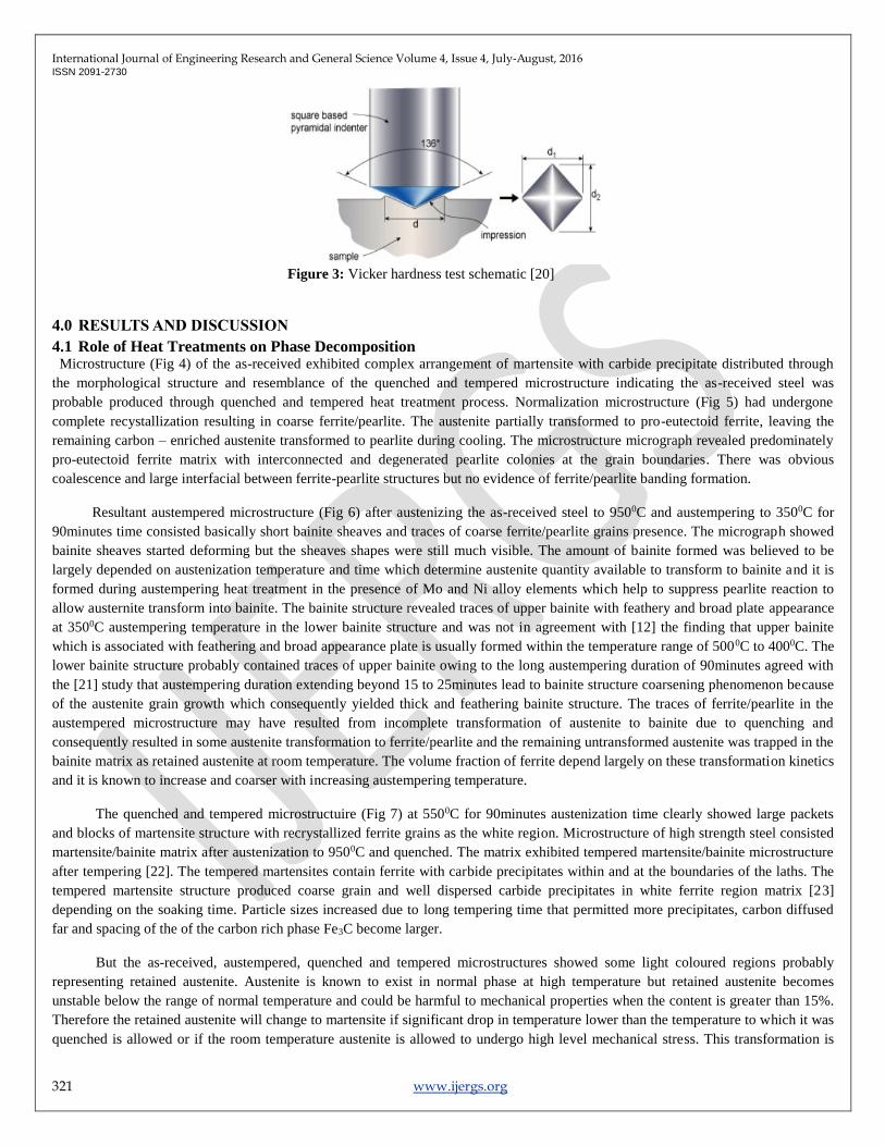
3.4 Hardness Testing Hardness test specimens were firstly cut from steel plate. Each specimen was encapsulated in a plastic for ease of handling and then
polished on 1micron after grinding with several emery paper grades. The hardness test was performed using Vicker measuring
technique with pyramidal diamond shaped tip indenter (Fig 3) which delivered load into the prepared surface of samples for a period
of 14 seconds as prescribed by ASTM E92 [19]. 15kg load from the machine was applied to six different points on the test surface
with indenter via weight lever and the vicker hardness value (Hv) calculated from the following mathematical expression:
𝐻𝑉 =1.8544𝐹
𝑑2
(4)
Where, 𝐹 = applied load and 𝑑 = diameter of indentation
Quantity Measured value (mm)
Specimen height (H) 1.2*W = 30.50
Specimen width (W) 25.40
Specimen thickness (B) 0.5*W = 12.70
Crack length (notch + pre-cracked)
0.45≤ 𝑎𝑜 𝑊⁄ ≤0.55.
Notch Length (n) 0.25*W = 6.35
Pre-cracking length (L) 0.05B =0.64
Notch height (N) 0.1*W =2.54
Span length (S) 0.55*W = 13.97
Pin hole diameter (d) 0.25*W = 6.35
Total specimen length (T) 1.25*W =31.75
International Journal of Engineering Research and General Science Volume 4, Issue 4, July-August, 2016 ISSN 2091-2730
321 www.ijergs.org
Figure 3: Vicker hardness test schematic [20]
4.0 RESULTS AND DISCUSSION
4.1 Role of Heat Treatments on Phase Decomposition Microstructure (Fig 4) of the as-received exhibited complex arrangement of martensite with carbide precipitate distributed through
the morphological structure and resemblance of the quenched and tempered microstructure indicating the as-received steel was
probable produced through quenched and tempered heat treatment process. Normalization microstructure (Fig 5) had undergone
complete recystallization resulting in coarse ferrite/pearlite. The austenite partially transformed to pro-eutectoid ferrite, leaving the
remaining carbon – enriched austenite transformed to pearlite during cooling. The microstructure micrograph revealed predominately
pro-eutectoid ferrite matrix with interconnected and degenerated pearlite colonies at the grain boundaries. There was obvious
coalescence and large interfacial between ferrite-pearlite structures but no evidence of ferrite/pearlite banding formation.
Resultant austempered microstructure (Fig 6) after austenizing the as-received steel to 9500C and austempering to 3500C for
90minutes time consisted basically short bainite sheaves and traces of coarse ferrite/pearlite grains presence. The micrograph showed
bainite sheaves started deforming but the sheaves shapes were still much visible. The amount of bainite formed was believed to be
largely depended on austenization temperature and time which determine austenite quantity available to transform to bainite and it is
formed during austempering heat treatment in the presence of Mo and Ni alloy elements which help to suppress pearlite reaction to
allow austernite transform into bainite. The bainite structure revealed traces of upper bainite with feathery and broad plate appearance
at 3500C austempering temperature in the lower bainite structure and was not in agreement with [12] the finding that upper bainite
which is associated with feathering and broad appearance plate is usually formed within the temperature range of 5000C to 4000C. The
lower bainite structure probably contained traces of upper bainite owing to the long austempering duration of 90minutes agreed with
the [21] study that austempering duration extending beyond 15 to 25minutes lead to bainite structure coarsening phenomenon because
of the austenite grain growth which consequently yielded thick and feathering bainite structure. The traces of ferrite/pearlite in the
austempered microstructure may have resulted from incomplete transformation of austenite to bainite due to quenching and
consequently resulted in some austenite transformation to ferrite/pearlite and the remaining untransformed austenite was trapped in the
bainite matrix as retained austenite at room temperature. The volume fraction of ferrite depend largely on these transformation kinetics
and it is known to increase and coarser with increasing austempering temperature.
The quenched and tempered microstructuire (Fig 7) at 5500C for 90minutes austenization time clearly showed large packets
and blocks of martensite structure with recrystallized ferrite grains as the white region. Microstructure of high strength steel consisted
martensite/bainite matrix after austenization to 9500C and quenched. The matrix exhibited tempered martensite/bainite microstructure
after tempering [22]. The tempered martensites contain ferrite with carbide precipitates within and at the boundaries of the laths. The
tempered martensite structure produced coarse grain and well dispersed carbide precipitates in white ferrite region matrix [23]
depending on the soaking time. Particle sizes increased due to long tempering time that permitted more precipitates, carbon diffused
far and spacing of the of the carbon rich phase Fe3C become larger.
But the as-received, austempered, quenched and tempered microstructures showed some light coloured regions probably
representing retained austenite. Austenite is known to exist in normal phase at high temperature but retained austenite becomes
unstable below the range of normal temperature and could be harmful to mechanical properties when the content is greater than 15%.
Therefore the retained austenite will change to martensite if significant drop in temperature lower than the temperature to which it was
quenched is allowed or if the room temperature austenite is allowed to undergo high level mechanical stress. This transformation is

International Journal of Engineering Research and General Science Volume 4, Issue 4, July-August, 2016 ISSN 2091-2730
322 www.ijergs.org
usually accompanied with volume change or geometry within the internal structure that may induce internal stress and manifest itself
as crack [24].
Figure 4: Microstructure of the as-received sample –a) LOM X200, b) SEM X5000
Figure 5: Microstructure of the normalized sample –a) LOM X200, b) SEM X5000
Figure 6: Microstructure of the austempered sample –a) LOM X200, b) SEM X5000

International Journal of Engineering Research and General Science Volume 4, Issue 4, July-August, 2016 ISSN 2091-2730
323 www.ijergs.org
Figure 7: Microstructure of the quenched & tempered sample –a) LOM X200, b) SEM X5000
4.2 Microstructure Impact on Mechanical Properties Microstructure impact on fracture toughness was evaluated using J-integral testing. Fig 8 shows normalized microstructure indicated
highest remarkable critical fracture toughness of 373kJ/𝑚2 , trailed by quenched and tempered (202kJ/𝑚2 ), as-received (138kJ/𝑚2 )
and then austempered microstructure (109kJ/𝑚2 ). Soft pro-eutectoid ferrite matrix presence was responsible for the remarkable
fracture toughness of normalization. The observation was in alignment with [11] the finding that steel impact toughness that had
undergone normalization appeared tougher than austempered and quenched and tempered microstructure. But the austempered
showed fracture toughness lower than the quenched and tempered due to presence of hard bainite matrix formation and possibly due
to excessive retained austenite throughout the structure while the quenched and tempered exhibited higher level fracture toughness due
to cementite precipitates, spheriodization and recrystallation ferrite matrix during tempering to 5500C. The toughness significant
margin was not in alignment with [25] the recommendation to replace conventional quenching and tempering with austempering
because of its better toughness owing to bainite-martensite or fully bainite structure composition.
Yield strengths were determined from stress-strain curves plotted on-line during tests. Comparative evaluation of the obtained
yield strengths (Fig 9) indicated austempered microstructure has the highest yield strength of 940MPa, followed by quenched and
tempered (780MPa), as-received (766MPa) and normalized microstructure (408MPa). The hardness results (Fig 10) showed marginal
variation in the samples that had undergone different heat treatment methods in the same chronological order with yield strength
which increased from austempered to normalization microstructure. The austempered microstructure showed highest average hardness
value of 318Hv, closely followed by quenched and tempered with 251Hv, as-received (246Hv) and normalized microstructure
(192Hv). The significant increase in the austempered yield strength and hardness values was attributed to hard constituent bainite
sheaves and grain density formation in the structure which implied bainite appearance increases both yield strength and hardness of
steel. But the quenched and tempered microstructure yield strength and hardness are slightly lower than the austempered despite
tempering due to the presence of cementite formation in the martensite matrix which is a harder constituent than martensite.
Contrastingly, the normalized sample indicated lowest yield strength and hardness values which suggested pro-eutectoid ferrite matrix
and pearlite appearance in the microstructure were responsible for the obtained low values implying they are softer constituent
compared with the bainite and martensite.
Figure 8: J-integral fracture toughness of microstructures chart

International Journal of Engineering Research and General Science Volume 4, Issue 4, July-August, 2016 ISSN 2091-2730
324 www.ijergs.org
Figure 9: Yield strengths of microstructures chart
Figure 10: Vicker hardness of microstructures chart
5.0 CONCLUSION
The present study has shown that upper bainite structure with feathery and broad plate appearance could be formed at 3500C and not
only within 5000C to 4000C depending on the isothermal holding period. Secondly, quenched and tempered microstructure indicated
the best combination of fracture toughness, yield strength and hardness trade-off compared with normalization, austempered and as-
received microstructures.
REFERENCES:
[1] J. Billingham, J. Healy, and H. Bolt “High strength steel- the significance of yield ratio and work hardening for structural
performance” Marine Research Review Pub MTD, 1997.
[2] B.S. Motagi and R. Bhosle “Effect of Heat Treatment on Microstructure and Mechanical Properties of Carbon Medium Steel”
International Journal of Engineering Research and Development, Vol. 2, Issue 1, 2012, Pp 07 – 13.
[3] E. Gogou “Use of High Strength Steel Grades for Economic Bridges Design”. Master Thesis, Delft University of technology,
2012.
[4] L.W. Ma, X. Wu and X. Kenong “Microstructure and property of medium carbon steel processed by equal channel angular
pressing” Material forum Vol. 32, 2008, Pub. Institute of materials engineering Australasia ltd.
[5] S. Al-rubaiey, E. Anon and M.M. Hanoon “The influence of microstructure on the corrosion rate of carbon steel” Engineering
and Technological Journal, vol.31, 2013, part (A) No 10.
[6] T. P. Arasu, R. Dhanasekaran, S. P. Kumar and N. Srinivasan “Effect of Hardness and Microstructure on En 353 Steel by Heat
Treatment” International Journal of Engineering and Science, vol 2, 2013, pp 01-05.
[7] S. Danda “Effect of Induction Hardening on High Carbon Steel Forgings” International Journal of Soft Computing and
Engineering, vol. 1, issue11, 2011, pp 01-05.
[8] S. S. Sharma, K. Jagannath, C. Bhat, U. Achutha Kini, P.R. Prabhu, P.K. Jayashree and M.C Gowrishankar “3 rd International
Conference on Mechanical” Automotive and Material Engineering, 2013, Singapore

International Journal of Engineering Research and General Science Volume 4, Issue 4, July-August, 2016 ISSN 2091-2730
325 www.ijergs.org
[9] S.M.A Al-Qawabah, N. Alshabatat, and U.F. Al-Qawabeha “Effect of Annealing Temperature on the Microstructure,
Microhardeness, Mechanical Behavior and Impact Toughness of Low Carbon Steel Grade 45”. International Journal of
Engineering Research and Application, vol 2, 2012, pp1550-1553.
[10] M. M. Tash “Effect of Hot Forging Reduction Ratio and Heat Treatment on Hardness, Impact Toughness and Microstructure of
Carbon and Low Alloy Steel” International Journal of Advanced Technology in Engineering and Science, Vol. 3, Issue 3, 2015.
[11] C.A. Reddy “Effect of holding temperature and time for austempering on impact toughness of medium carbon and high alloy
steel” International Journal of Computer Network and Security, vol 3, 2013.
[12] X. Lian “The Complex Phase Transformation of Austenite in High Strength lineup steels and its influence on the mechanical
properties” Doctoral thesis, University of Pittsburgh, 2012.
[13] O. O. Joseph*1, O. O. Joseph*2, R. O. Leramo and O. S. Ojudun “Effect of Heat Treatment on Microstructure and Mechanical
Properties of SAE 1025 Steel: Analysis by one – way ANOVA” J. Mater. Environ. Sci, Vol. 6, 2015, Pp 101 – 106.
[14] D.A. Fadare, T.G. Fadara and O. Y. Akanbi “Effect of Heat Treatment on Mechanical Properties and Microstructure of NST 37-2
Steel” Journal of Minerals and Materials Characterization & Engineering, Vol. 10, Issue 3, 2011.
[15] M.S. Htun, S.T. Kyaw and K.T. Lwin “Effect of Heat Treatment on Microstructure and Mechanical Properties of Spring”
Journal of Metals, Materials and Mineral, vol 18, 2008, pp 191 – 197.
[16] ASM International, ASM Handbook: Heat Treatment, Vol. 4, American Society for Metals, Ohio, 1999.
[17] ASTM E1820 “Standard test method for measurement of fracture toughness” Pub. ASTM International USA, 2010.
[18] ASTM E8 “Standard Test Method for Tension Testing of Metallic Materials” Pub. ASTM International USA, 2012.
[19] ASTM E92 “Standard Test Method for Vicker Hardness and Knoop Hardness of Metallic Materials” Pub ASTM International,
2016.
[20] G. Mathers, Hardness Testing Part 1, Article of TWI, 2005, Pp 4 – 5.
[21] C. Chen, Fei-Yi, L. Truan-Sheng, and C. Li-Hui “Microstructure and Mechanical Properties of Austempering Cr-Mo alloy
steel”. Journal of Materials Transaction, vol 5, 2013, pp 56 – 60.
[22] J. D. Verhoeven “Fundamental of Physical Metallurgy” Pub. John Willey & Son, 1975.
[23] W. Callister “Material Science and Engineering. An Integrated Approach” Second edition. Pub. John Wiley and sons, Inc, 2005.
[24] D. H. Herring “Vacuum Heat Treatment: Principles, Practices and Application” Second Edition, Pub BNP Media, 2005.
[25] J. Wen, Q. Li and Y. Long “Effect of Austempering and Mechanical Properties of GCr18Mo Steel” Material Science
Engineering A, 2006, pp 251 – 253.


![International Journal of Engineering Research and General ...pnrsolution.org/Datacenter/Vol4/Issue6/30.pdf · The concept of two dimensional classical theories of lubrication [3],](https://img.dokumen.tips/doc/110x75/5d5212af88c993730d8b6c34/international-journal-of-engineering-research-and-general-the-concept-of.jpg)