Embed Size (px)
Citation preview

INTERLIFT
Minifix INSTALLATION MANUAL
& CHECK-OFF SHEET Rev. 1.2, Date: 07-05-11
INTERLIFT, INC. dba MBB Palfinger
15939 Piuma Ave., Cerritos, CA 90703 Tel (888)-774-5844 Fax (562)-924-8318
572 Whitehead Road, Trenton, NJ 08619 Tel (609)-587-4200 Fax (609)-587-4201
Visit our website at www.interlift.net for up to date information and notifications
If you received this product with damaged or missing parts,
Please contact Interlift at (888)-774-5844
MINIFIX INSTALLATION MANUAL
Revision 1.2 2
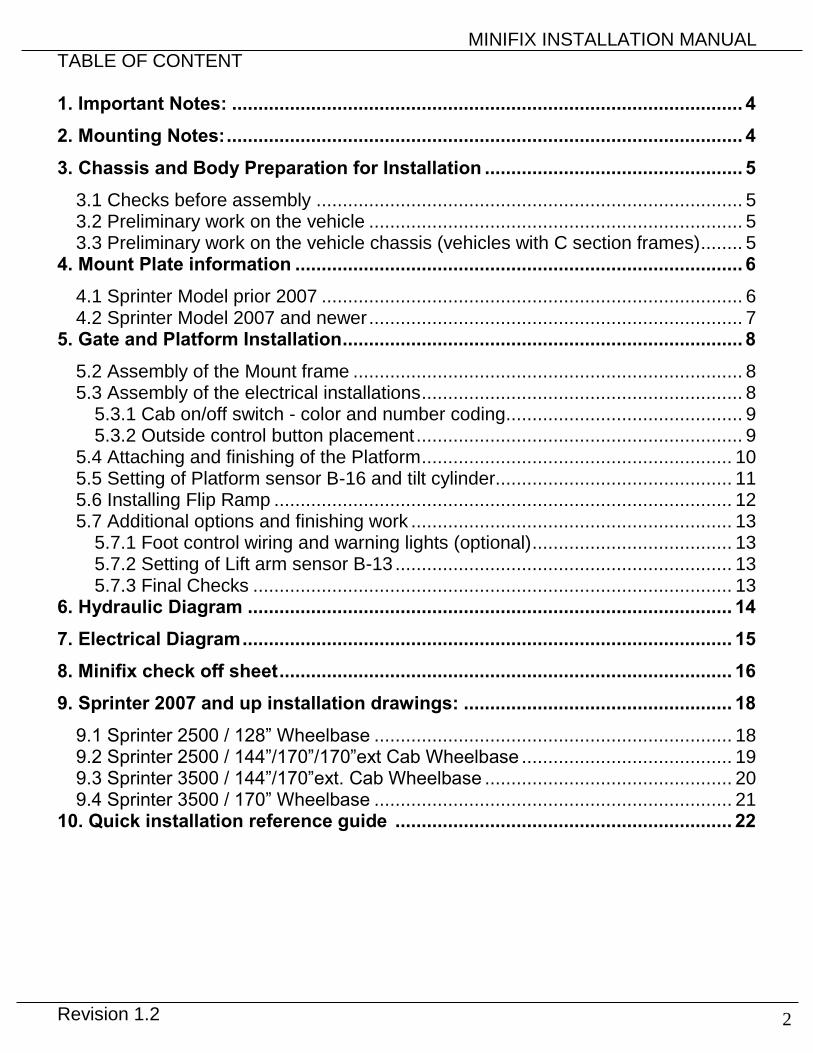
TABLE OF CONTENT 1. Important Notes: ................................................................................................. 4
2. Mounting Notes: .................................................................................................. 4
3. Chassis and Body Preparation for Installation ................................................. 5
3.1 Checks before assembly ................................................................................. 5
3.2 Preliminary work on the vehicle ....................................................................... 5
3.3 Preliminary work on the vehicle chassis (vehicles with C section frames) ........ 5
4. Mount Plate information ..................................................................................... 6
4.1 Sprinter Model prior 2007 ................................................................................ 6
4.2 Sprinter Model 2007 and newer ....................................................................... 7
5. Gate and Platform Installation ............................................................................ 8
5.2 Assembly of the Mount frame .......................................................................... 8
5.3 Assembly of the electrical installations ............................................................. 8
5.3.1 Cab on/off switch - color and number coding ............................................. 9
5.3.2 Outside control button placement .............................................................. 9
5.4 Attaching and finishing of the Platform ........................................................... 10
5.5 Setting of Platform sensor B-16 and tilt cylinder............................................. 11
5.6 Installing Flip Ramp ....................................................................................... 12
5.7 Additional options and finishing work ............................................................. 13
5.7.1 Foot control wiring and warning lights (optional) ...................................... 13
5.7.2 Setting of Lift arm sensor B-13 ................................................................ 13
5.7.3 Final Checks ........................................................................................... 13
6. Hydraulic Diagram ............................................................................................ 14
7. Electrical Diagram ............................................................................................. 15
8. Minifix check off sheet ...................................................................................... 16
9. Sprinter 2007 and up installation drawings: ................................................... 18
9.1 Sprinter 2500 / 128” Wheelbase .................................................................... 18
9.2 Sprinter 2500 / 144”/170”/170”ext Cab Wheelbase ........................................ 19
9.3 Sprinter 3500 / 144”/170”ext. Cab Wheelbase ............................................... 20
9.4 Sprinter 3500 / 170” Wheelbase .................................................................... 21
10. Quick installation reference guide ................................................................ 22
MINIFIX INSTALLATION MANUAL
Revision 1.2 3
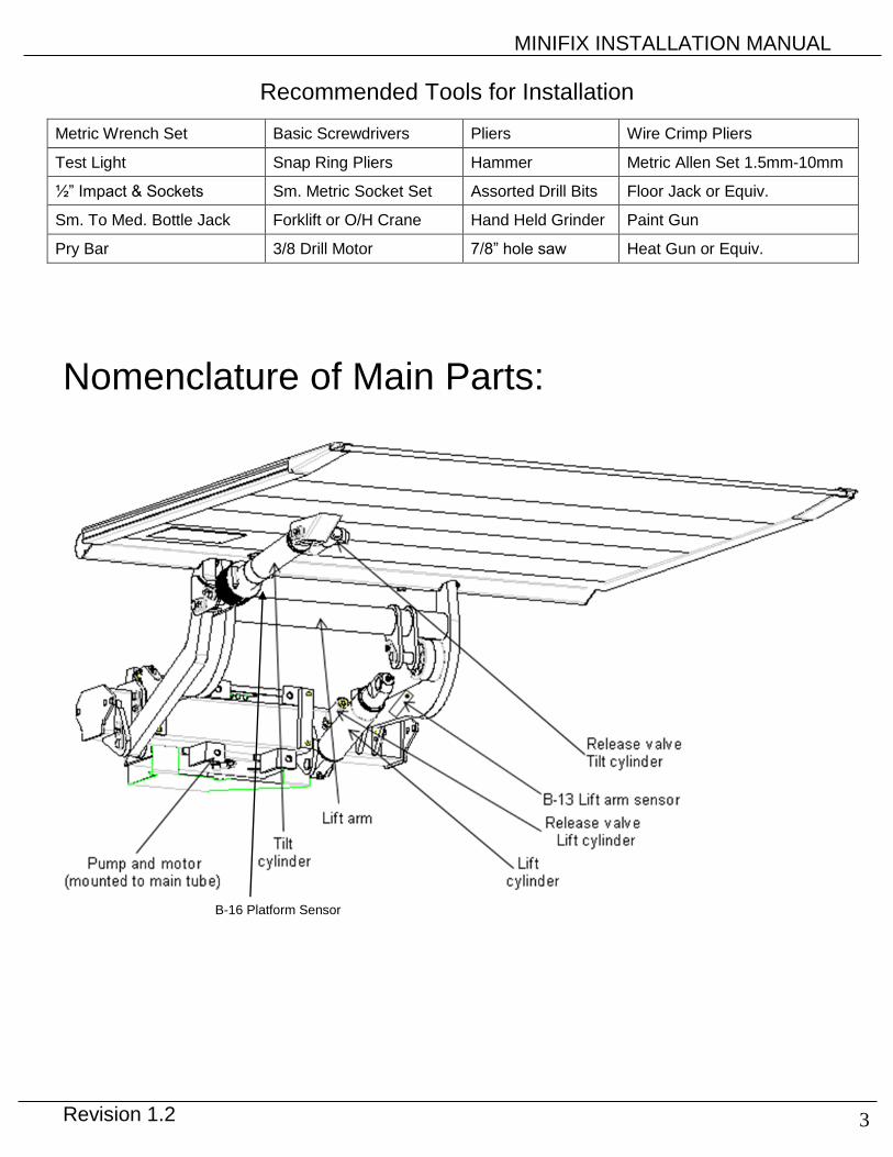
Recommended Tools for Installation
Metric Wrench Set Basic Screwdrivers Pliers Wire Crimp Pliers
Test Light Snap Ring Pliers Hammer Metric Allen Set 1.5mm-10mm
½” Impact & Sockets Sm. Metric Socket Set Assorted Drill Bits Floor Jack or Equiv.
Sm. To Med. Bottle Jack Forklift or O/H Crane Hand Held Grinder Paint Gun
Pry Bar 3/8 Drill Motor 7/8” hole saw Heat Gun or Equiv.
Nomenclature of Main Parts:
B-16 Platform Sensor
MINIFIX INSTALLATION MANUAL
Revision 1.2 4
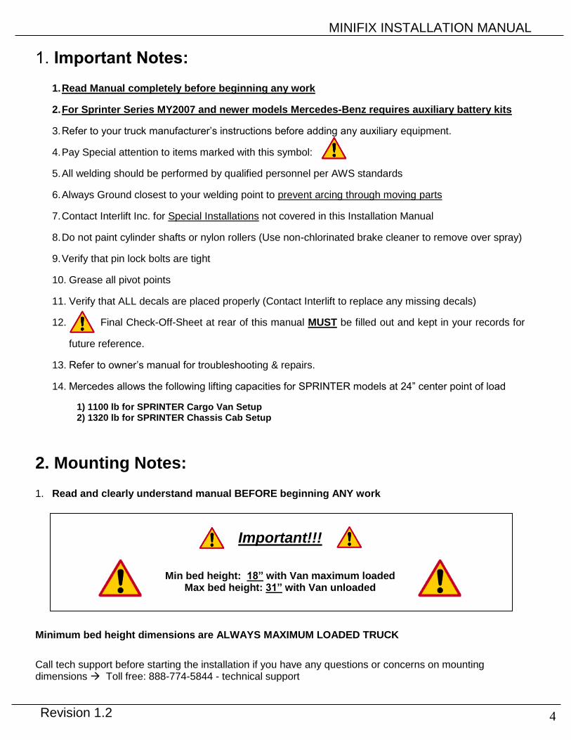
1. Important Notes:
1. Read Manual completely before beginning any work
2. For Sprinter Series MY2007 and newer models Mercedes-Benz requires auxiliary battery kits
3. Refer to your truck manufacturer’s instructions before adding any auxiliary equipment.
4. Pay Special attention to items marked with this symbol:
5. All welding should be performed by qualified personnel per AWS standards
6. Always Ground closest to your welding point to prevent arcing through moving parts
7. Contact Interlift Inc. for Special Installations not covered in this Installation Manual
8. Do not paint cylinder shafts or nylon rollers (Use non-chlorinated brake cleaner to remove over spray)
9. Verify that pin lock bolts are tight
10. Grease all pivot points
11. Verify that ALL decals are placed properly (Contact Interlift to replace any missing decals)
12. Final Check-Off-Sheet at rear of this manual MUST be filled out and kept in your records for
future reference.
13. Refer to owner’s manual for troubleshooting & repairs.
14. Mercedes allows the following lifting capacities for SPRINTER models at 24” center point of load
1) 1100 lb for SPRINTER Cargo Van Setup 2) 1320 lb for SPRINTER Chassis Cab Setup
2. Mounting Notes: 1. Read and clearly understand manual BEFORE beginning ANY work
Important!!!
Min bed height: 18” with Van maximum loaded Max bed height: 31” with Van unloaded
Minimum bed height dimensions are ALWAYS MAXIMUM LOADED TRUCK
Call tech support before starting the installation if you have any questions or concerns on mounting dimensions Toll free: 888-774-5844 - technical support

MINIFIX INSTALLATION MANUAL
Revision 1.2 5
√
3. Chassis and Body Preparation for Installation 3.1 Checks before assembly
1. Does the liftgate match your order?
2. Do you have the correct mount plates for your particular chassis?
- Each Sprinter chassis requires it own specific mount plates.
3. Are the assembly instructions for the MBB Interlift Minifix included?
4. Does the operating voltage of the MBB Interlift Minifix match the vehicle voltage?
5. Is a flip ramp included?
6. Observe the chassis guidelines of the vehicle manufacturer for accessory equipment.
7. Check size of battery for adequate capacity.
8. Is there a compartment under passenger seat designed for an auxiliary battery?
Special tools required: 7/8” hole saw for installation of switches in side panel and basic metric wrenches.
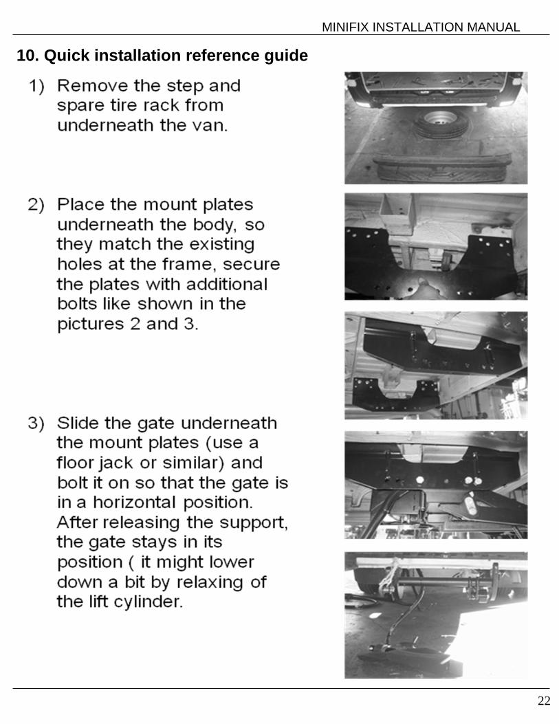
3.2 Preliminary work on the vehicle 1. Remove any spare wheels and their mounts from the vehicle rear underside.
2. Remove any trailer and towing hitches as well as steps attached to the rear of the vehicle.
3. Replace special step bumpers fitted with standard bumpers.
4. Remove the licence plate on the rear doors and re-attach it in a visible position after assembly of the MBB Minifix (observe local and federal regulations).
3.3 Preliminary work on the vehicle chassis (vehicles with C section frames) 1. The MBB Minifix is supplied with vehicle-specific mount plates and fitted by means of the supplied assembly kit.
2. The 4 ea. drilled holes at the rear of chassis (i.e. mount for the trailer hitch) are used for bolting the mount plate to chassis.
3. Additional forward placed mounting points on the mount plates are to be drilled in the chassis frame.
Platform

MINIFIX INSTALLATION MANUAL
Revision 1.2 6
single wheel 118"/140"WB single wheel 158"WB
dual wheel 140"WB dual wheel 158"WB
18-1/4" 26-1/2"
29-1/2"23"
Left: P-2005081Right: P-2005083
Left: P-2004489Right: P-2004492
Left: P-2008031Right: P-2008033
Left: P-2004501Right: P-2004504
4. Mount Plate information VERY IMPORTANT: To install the Lift Gate it is very important to have the right mount plates. They are dependent on the Wheelbase (WB) and Chassis type:
- Chassis 2500: Single Rear Wheel
- Chassis 3500: Dual Rear Wheel
4.1 Sprinter Model prior 2007
MINIFIX Installations Kit
# QTY Description
1 18 Lock Washer 1/2" (12mm)
2 18 Nuts 1/2" (12 mm)
3 36 Washer 1/2" (12mm)
4 12 Bolts 1/2" x 4" (12mm x 100mm)
5 6 Bolts 1/2" x 1,5" (12mm x 40mm)

MINIFIX INSTALLATION MANUAL
7
17-1/4" 18-1/4"
24"
P-2012508 le
P-2012512 le/ri
P-2012510 riP-2012763 leP-2012766 ri
2500 - 128” WB 3500 – 170” WB
2500/3500 – 144” / 170” / 170” ext. Cab WB
4.2 Sprinter Model 2007 and newer
The Chassis and the dimensions have changed beginning with the Model year 2007. Images below and matrix are showing the available models and the according mount plates
Chassis WB Mount Plates (left / right)
Spacer Mounting Kit
2500 128” 2012508 / 2012510 - 2004579
2500 144”/170”/170 ext Cab 2012512 - 2004579
3500 144”/170” ext. Cab 2012512 Only 144” / 4ea. P-2012762 2004579
3500 170” 2012764 / 2012766 2ea. P-2012760 2012768
Mount plates:
Mounting Kit 2004579 Mounting Kit 2012768
Quantity Parts Quantity Parts 24 Washer 24 Washer
12 Nuts M12 12 Nuts M12
12 Bolts M12x100 8 Bolts M12x120
4 Bolts M12x100
P-2012764 le
P-2012766 ri

MINIFIX INSTALLATION MANUAL
8
RES
ET
5. Gate and Platform Installation
Installation drawings for each mounting situation are attached at the end of this manual (see 10. Sprinter 2007 and up installation drawings - Page20-23)
5.2 Assembly of the Mount frame 1. Vehicle-specific mounting plates are fitted by means of the supplied assembly kit.
2. The power pack unit is normally mounted on the forward surface of the mount frame. If there is insufficient depth for installation, mount the unit elsewhere on chassis.
3. Install the mount plates first with the 4 bolts at the rear - leave the plates somewhat loose so there is room to install the mount frame in between them.
4. Bring the mount frame into position underneath the vehicle using a floor jack and bolt into position with the supplied 6 ea M 14 bolts (grade 8 - 9/16” bolts)
5. After the mount frame is in place, drill the two forward holes in the frame and install these bolts. Do not tightening all the bolts until the gate is operational and platform is in place.
6. Finish the tightening of the 12 ea. Mount plates to frame bolts after unit is operational and in place to determine that the platform is storing square to body and meets floor height.
5.3 Assembly of the electrical installations 1. Use the attached MBB Minifix electric schematic (see page 14) and observe the
set-up guidelines of the vehicle OEM.
2. Run the battery cables to the battery. Make sure not to route any wires in a way where it get damaged or damages the vehicle harnesses.
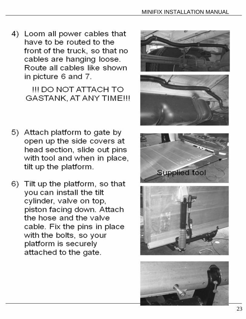
Shorten cables if required and affix cable lugs! Do not attach power cable to gas tank or gas filler hose!
3. Attach circuit breaker (see picture 1) to the cable lug, connect with copper brass bar to the positive pole of the battery.
4. Route the control unit harness to the cab. Choose a location on the instrument panel in the cab and install cab on/off switch within view of the driver.
5. If the vehicle already has a factory install cab on/off switch, connect MBB Minifix in accordance with MBB supplementary circuit diagram; if necessary, request circuit diagram from MBB.
6. Make sure there is sufficient ground connection between lift gate power pack and batteries.
7. WARNING! On hazardous goods vehicles, connect the ground cable to the battery or in accordance with the set-up guidelines of the respective vehicle manufacturer.
picture 1: resettable circuit breaker 150 Amp
Hubwerk
Switch b13 horizontal
Rod head
Detail Z
Angle sensor b16
Detail X

MINIFIX INSTALLATION MANUAL
9
Green/Yellow (-)
White (#1)
Blue (BS3)
Red (#2)
Blue (#4)
"Off" Symbol
5.3.1 Cab on/off switch - color and number coding
5.3.2 Outside control button placement Mount operating buttons on right side rear of body (see diagram below). Center switches approximately 15” from rear of corner post.
9"
3"
ø 7/8"
OEF Z.T
SE Function of push buttons: OEF = tilt open platform
SE = lowering platform
SE+ZT = lift up platform
OEF+ZT = tilt close platform
8. Installation of hand remote must be set up in a way where it can’t be damaged during normal operation. The operating buttons must be arranged in accordance with the diagram above. The operating decal gives circuit logic details. The operating decal is furnished with a self-adhesive reverse side and is applied directly to the panel of the vehicle outer wall.
Cable wires are marked: #1 = Status lights for L.E.D. Lights - WHITE
#(-) = Ground to L.E.D. Lights - GREEN/YELLOW
#2 = 12 Volt Lead from Batteries - RED
#4 = Control Power to Lift gate - BLUE
MINIFIX INSTALLATION MANUAL
10
Lines for alignment
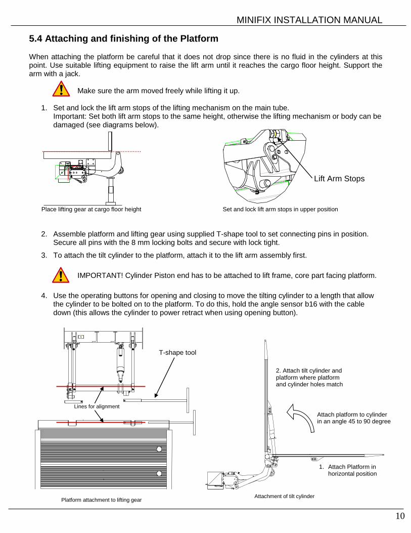
5.4 Attaching and finishing of the Platform When attaching the platform be careful that it does not drop since there is no fluid in the cylinders at this point. Use suitable lifting equipment to raise the lift arm until it reaches the cargo floor height. Support the arm with a jack.
Make sure the arm moved freely while lifting it up.
1. Set and lock the lift arm stops of the lifting mechanism on the main tube. Important: Set both lift arm stops to the same height, otherwise the lifting mechanism or body can be damaged (see diagrams below).
Place lifting gear at cargo floor height Set and lock lift arm stops in upper position
2. Assemble platform and lifting gear using supplied T-shape tool to set connecting pins in position. Secure all pins with the 8 mm locking bolts and secure with lock tight.
3. To attach the tilt cylinder to the platform, attach it to the lift arm assembly first.
IMPORTANT! Cylinder Piston end has to be attached to lift frame, core part facing platform.
4. Use the operating buttons for opening and closing to move the tilting cylinder to a length that allow the cylinder to be bolted on to the platform. To do this, hold the angle sensor b16 with the cable down (this allows the cylinder to power retract when using opening button).
Lift Arm Stops
T-shape tool
Platform attachment to lifting gear
1. Attach Platform in horizontal position
2. Attach tilt cylinder and platform where platform and cylinder holes match
Attachment of tilt cylinder
Attach platform to cylinder in an angle 45 to 90 degree

MINIFIX INSTALLATION MANUAL
11
Picture 3: installation
of rubber bumper
5.5 Setting of Platform sensor B-16 and tilt cylinder 1. Mount the platform sensor b16 to the platform clip, as shown in picture 1, so that the filling faces towards
the driver side. 2. Move the lifting gear all the way up to the truck bed against the lift arm stops to insure horizontal platform
is flush with the truck bed. If necessary, readjust lift arm stops.
B-16 sensorfilling towards driver side
Adjust tilt cylinderclevis and lock inplace with lock nutwhen platform is infinal position
Picture 1: B-16 setup Picture 2: adjusting tilt cylinder
3. Remove the emblem on the back door and replace with supplied
triangle rubber bumper, like shown in picture 3. Close the platform to the body as far as possible, make sure the platform does not hit the body. (Tilting cylinder is extended to the limit stop = (max stroke!!)) Relieve the pressure in the tilt cylinder by hitting the “open” button. By turning the piston rod, using an open-end wrench, you are able to adjust the length of the piston to store platform into the designated position. If required, repeat the setting procedure. With platform in position, tighten the lock nut of the piston.(see picture 2)
For the final position of the platform the tilting cylinder must be extended to the full stroke in the closing position. Make sure, lift arm is all the way up against the lift arm stops. The platform must not hit the body in any circumstances as this can otherwise damage the body.
Truckbody
Rubber
bumper
MINIFIX INSTALLATION MANUAL
12
2.0"
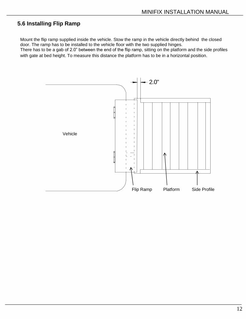
5.6 Installing Flip Ramp
Mount the flip ramp supplied inside the vehicle. Stow the ramp in the vehicle directly behind the closed door. The ramp has to be installed to the vehicle floor with the two supplied hinges. There has to be a gab of 2.0” between the end of the flip ramp, sitting on the platform and the side profiles
with gate at bed height. To measure this distance the platform has to be in a horizontal position.
Vehicle
Platform Flip Ramp Side Profile

MINIFIX INSTALLATION MANUAL
13
Secure the harness so it does notget damaged during operation
Position for adjusting B-13 Switch
8" to 10"
bend clip to secure
B 13 switch after tightening
B 13 switch position
bend clip to secure B 13 switch after tightening
5.7 Additional options and finishing work
5.7.1 Foot control wiring and warning lights (optional)
1. Close the platform up towards the body.
2. Loosen cable retainer (black plastic cap on the head section of the platform), pull the cable with the plug for the foot-operated switch and warning light out of the platform (make sure there is enough cable length!) and refit the cable retainer. Run the cable along with the release valve cable at the hydraulic hose and connect the plug on the board.
5.7.2 Setting of Lift arm sensor B-13
1. All fitted cables must be routed carefully and secured.
2. Lower the platform to about 8”-10” above the ground and set the lift arm switch b13 on the lift arm in a horizontal position.
3. Loosen the M6 adjustment bolt, retighten after setting and bend the metal clip to fix position of the switch.
5.7.3 Final Checks 1. Raise, lower, open and close the platform several times to de-aerate the cylinders.
2. Use the brackets on the platform underside as holders for the hydraulic hoses and electrical cable that
extend out of the platform.
3. Check the oil level with the platform lowered. Check that all electrical, hydraulic and mechanical connections are tight and that no wires are rubbing during the gate operation.
Counter nut
Detail Z
Angle sensor b16
Detail X

MINIFIX INSTALLATION MANUAL
14
Functions:
Lift: MLower: S1+ S5Tilt Up: M+S5Tilt Down: S2Horiz. Open: M+S2
Pressure Relief
2850 PSI200 bar
Shift Valve S5
Restrictor Valve R5
Flow Divider
Functions:
S1 = Release Valve for lowering functionS2 = Release Valve for tilt down functionR1 = Flow Restrictor located inside hose adaptor on lift cylinderR2 = Flow Restrictor located inside hose adaptor on tilt cylinderS5 = Shift Valve is activated on tilt up and lowering functionR5 = Restrictor Valve located in power packFlow Divider is activated, when fluid is going back into the power packIf Flow Divider is loose or hanging up the fluid is circulated back in to tank
2
2
Datum
01.08.08
Hydraulic Schematic
HACKBARTH
Minifix
6. Hydraulic Diagram

MINIFIX INSTALLATION MANUAL
15
150
MIN
IFIX
K
1P
LU
S
WIR
ELE
SS
HA
ND
CO
NT
RO
L
OP
TIO
NA
L
O
PT
ION
AL
WA
RN
ING
LIG
HT
S &
F
OO
T C
ON
TR
OL
4 W
IRE
CA
BLE
2 G
A C
AB
LE
# 2
BLA
CK
# 4
BLA
CK
# 1
BLA
CK
GR
EE
N / Y
ELLO
W
(+)
(-)
LI : L
ift U
pLO
: L
ow
er
Dow
nO
P : O
pen G
ate
CL
: C
lose
Gate
CIR
CU
IT B
OA
RD
Legend
:
gn : g
reen
bl :
blu
ebr
: bro
wn
wt : w
hite
ye : y
ello
wbk
: bla
ckgy
: gre
en-y
ello
w
7. Electrical Diagram

MINIFIX INSTALLATION MANUAL
16
8. Minifix check off sheet
MINIFIX Check Off Sheet
JOB NO.
GATE NO. VIN NO.
OWNER'S MANUAL IN CAB
ON-OFF SWITCH WORKING & DECAL IN PLACE
WIRING 1. Power Cord Secured OPERATION 1. All Functions
2. Cables Not Rubbing Steel Up/Down, tilt up down
3. 12V Control Wire Secured Hand remote/ foot controls
4. Loomed & Stapled 2. Up Stops In Place
5. Circuit Breaker & Fuse 3. Platform Meets Body
Installed & Decal In Place
HYD. LINES 1. No Rubbing On Frame
SECURED 2. No Rubbing On Platform
3. Up-Down Clear 4. 24mm Platform Bolts Tight
4. Storing Platform Clear
HYD. OIL 1. None At Hoses
LEAKS 2. None Power Pack FINAL 1. Piston rod clean from paint
3. Cylinder INSPECTION 2. Lights Working On Chassis
3. Lic. Plate Bolts & Lights
4. Decals Installed
5. Rubber & Plastic Caps
In Place
6. Gate Painted Completely
7. Body Clean Around Gate
8. Pins Greased -
PUMP 1. Check Fluid With Platform On Ground

MINIFIX INSTALLATION MANUAL
17
& MOTOR 2. Connections Tight With Heat Shrink
3. Power Cable Tight OPTIONS 1. All Options On Gate
4. Ground Cable Tight 2. Circuit Breaker Working
5. Breather Installed & Decal In Place
6. Cables Tied Off 3. Cart Stops Working
7. Fuses Tight
CHECKED BY
PINS 1. Grease Zerks In Place
2. Red Grease Caps On Zerks DATE
3. Bolts Tight On Pins
Note:
Interlift recommends that this form is filled out and kept for your records.

MINIFIX INSTALLATION MANUAL
18
9. Sprinter 2007 and up installation drawings:
9.1 Sprinter 2500 / 128” Wheelbase
MINIFIX INSTALLATION MANUAL
19
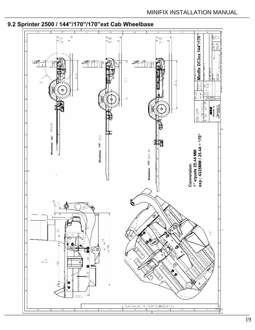
9.2 Sprinter 2500 / 144”/170”/170”ext Cab Wheelbase

MINIFIX INSTALLATION MANUAL
20
9.3 Sprinter 3500 / 144”/170”ext. Cab Wheelbase

MINIFIX INSTALLATION MANUAL
21
9.4 Sprinter 3500 / 170” Wheelbase
MINIFIX INSTALLATION MANUAL
22
10. Quick installation reference guide
1
3
5
MINIFIX INSTALLATION MANUAL
23

MINIFIX INSTALLATION MANUAL
24

MINIFIX INSTALLATION MANUAL
25