Embed Size (px)
Citation preview

MiniFix
OWNER’S MANUAL
ECN-M0262 Rev. 1.1, Date 07-15-2013 Part #90-0913-100
PALFINGER Liftgates, LLC. 15939 Piuma Ave., Cerritos, CA 90703
Tel (888)-774-5844 Fax (562)-924-8318
PALFINGER Liftgates, LLC. 572 Whitehead Road, Trenton, NJ 08619
Tel (609)-587-4200 Fax (609)-587-4201
Visit our website at www.palfinger.com for up to date information and notifications
If you received this product with damaged or missing parts,
Please contact PALFINGER Liftgates at (888)-774-5844
I
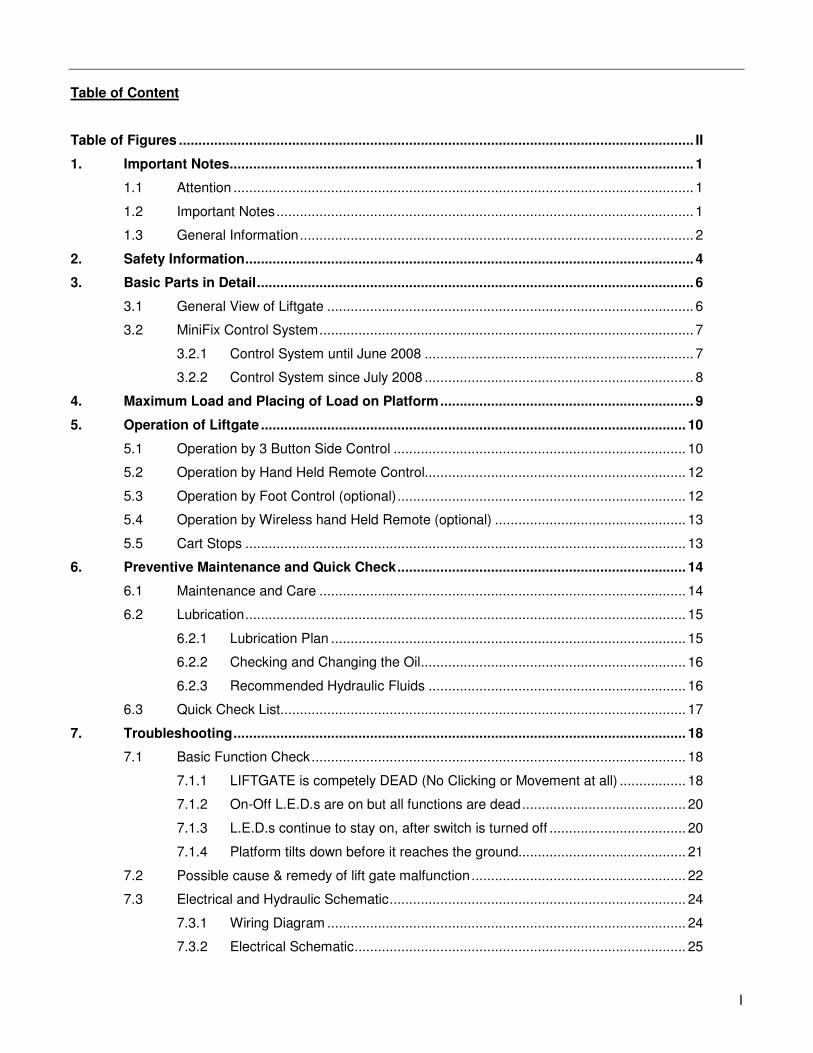
Table of Content
Table of Figures .................................................................................................................................... II
1. Important Notes ....................................................................................................................... 1
1.1 Attention ...................................................................................................................... 1
1.2 Important Notes ........................................................................................................... 1
1.3 General Information ..................................................................................................... 2
2. Safety Information ................................................................................................................... 4
3. Basic Parts in Detail ................................................................................................................ 6
3.1 General View of Liftgate .............................................................................................. 6
3.2 MiniFix Control System ................................................................................................ 7
3.2.1 Control System until June 2008 ..................................................................... 7
3.2.2 Control System since July 2008 ..................................................................... 8
4. Maximum Load and Placing of Load on Platform ................................................................. 9
5. Operation of Liftgate ............................................................................................................. 10
5.1 Operation by 3 Button Side Control ........................................................................... 10
5.2 Operation by Hand Held Remote Control................................................................... 12
5.3 Operation by Foot Control (optional) .......................................................................... 12
5.4 Operation by Wireless hand Held Remote (optional) ................................................. 13
5.5 Cart Stops ................................................................................................................. 13
6. Preventive Maintenance and Quick Check .......................................................................... 14
6.1 Maintenance and Care .............................................................................................. 14
6.2 Lubrication ................................................................................................................. 15
6.2.1 Lubrication Plan ........................................................................................... 15
6.2.2 Checking and Changing the Oil .................................................................... 16
6.2.3 Recommended Hydraulic Fluids .................................................................. 16
6.3 Quick Check List ........................................................................................................ 17
7. Troubleshooting .................................................................................................................... 18
7.1 Basic Function Check ................................................................................................ 18
7.1.1 LIFTGATE is competely DEAD (No Clicking or Movement at all) ................. 18
7.1.2 On-Off L.E.D.s are on but all functions are dead .......................................... 20
7.1.3 L.E.D.s continue to stay on, after switch is turned off ................................... 20
7.1.4 Platform tilts down before it reaches the ground........................................... 21
7.2 Possible cause & remedy of lift gate malfunction ....................................................... 22
7.3 Electrical and Hydraulic Schematic ............................................................................ 24
7.3.1 Wiring Diagram ............................................................................................ 24
7.3.2 Electrical Schematic ..................................................................................... 25

Revision 1.1 II
7.3.3 Connector Overview .................................................................................... 26
7.3.4 Hydraulic Schematic .................................................................................... 27
8. Needed Information for Ordering Spare Parts and Repairs ............................................... 28
8.1 Ordering Spare Parts ................................................................................................. 28
8.2 Repairs ...................................................................................................................... 28
9. Warranty ................................................................................................................................ 29
10. Contact Address ................................................................................................................... 30
Table of Figures
Figure 1: MiniFix (General Overview) .................................................................................................. 6
Figure 2: Center Point of Load ............................................................................................................. 9
Figure 3: Load Diagram (MiniFix 11) .................................................................................................... 9
Figure 4: 3 Button Side Control ......................................................................................................... 10
Figure 5: Lube Points ................................................................................................................ 15
Figure 6: Power Pack (Simplified View) ............................................................................................ 16
Figure 7: Main Wiring ................................................................................................................ 24
Figure 8: Electrical Schematic ........................................................................................................... 25
Figure 9: Connector Overview ........................................................................................................... 26
Figure 10: Hydraulic Schematic ......................................................................................................... 27
List of Tables
Table 1: Maintenance Schedule ......................................................................................................... 14
Table 2: Recommended Hydraulic Fluids ......................................................................................... 16
Table 3: Warranty Coverage Schedule .............................................................................................. 29
Revision 1.1 1
1. Important Notes
1.1 Attention
Before starting any operations of the liftgate, please read and understand this OWNER’S MANUAL. Its
intention is to act as a guide for the operation personal as well as to give help with preventive maintenance but
does not take place of unauthorized usage or repair by unqualified personnel.
Please contact your nearest PALFINGER Liftgates distributor or PALFINGER Liftgates in California or New
Jersey for assistance if you have questions regarding installation, operation or maintenance.
This owner’s manual applies to the following models: MiniFix
This is the safety alert symbol. It is used to alert you to potential personal injury hazards. Obey all
safety messages that follow this symbol to avoid possible injury.
1.2 Important Notes
Your PALFINGER Liftgates MiniFix is a cargo van lift design, electro-hydraulically driven lift gate.
The Hydraulic Power Unit (HPU) is easily accessible for service and exchange and is placed in a box
underneath the Truck.
Lifting actions are carried out by one hydraulic lift cylinder mounted to the lift arm.
The hydraulic tilt cylinder under the platform is controlling the tilting action. This enables the platform to
maintain its position throughout the lift mode, regardless of the terrain.
The hydraulic cylinders are equipped with solenoid operated valves located at the port of each cylinder. This
prevents the platform from moving unless the operator is activating the controls. This system also enables you
to store the lift gate without a separate platform latch.
The piston rods are treated against corrosion and also protected with plastic or rubber boots to protect from
road gravel and dirt. The Hydraulic Power Unit is equipped with a built-in pressure relief valve, which prevents
overloading when lifting and tilting up.
The valves do not prevent overloading of the platform when lowering or tilting down.
The electric supply is taken from the vehicle battery. If the vehicle battery is not sufficient, an auxiliary battery
kit needs to be installed. The electric control power is secured via a 20 Amp fuse and an on-off switch located
inside the cab. The switch has L.E.D. lights indicating when the control power is on.
Revision 1.1 2
The liftgate is operated from a 3-button outside control which is located on the curbside of your truck.
A standard 2-button hand held remote control is also supplied with the lift. A variety of different control options
can be purchased with the PALFINGER Liftgates product.
1.3 General Information
REMEMBER!
It is the fleet manager’s responsibility to educate the operator on the liftgate and its intended use. The
operator’s attention should be drawn to the permitted load limits and an understanding of the operation to
ensure the safety throughout the operation.
ONE-MAN OPERATION!
Never let an “outsider” operate the liftgate while you are handling the cargo.
A “misunderstanding” can result in serious personal injury.
In the interest of safety it is important that all operating personnel properly understand the functions of
the liftgate, possible hazards and dangers and the load limits and load positioning for that specific unit.
IMPORTANT NOTICE!
Before the operator uses the liftgate, they should be thoroughly familiar with the lift’s functions and
usage according to the following:
1. Improper operation of this lift can result in serious personal injury. Do not operate unless you have
been properly instructed, have read and are familiar with the operation instructions. If you do not have
a copy of the instructions please obtain them from your employer, distributor or lessor, as appropriate,
before you attempt to operate the lift.
2. Be certain the vehicle is properly and securely stopped before using the lift.
3. Always inspect this lift for maintenance or damage before using it. If there are signs of improper
maintenance, damage to vital parts or slippery platform surface, do not use the lift. Do not attempt
your own repairs unless you are specifically trained.
4. Do not overload. See the Rating Label on the unit for the rated load. Remember that this limit applies
to both raising and lowering operations.
5. Each load should be placed in a stable position as near as possible to the body of the truck.
Revision 1.1 3
6. Never stand in, move through or allow anyone else to stand in or move through the area in which the
lift operates, including that area in which a load might fall.
7. This is not a passenger lift. Do not ride the lift with unstable loads or in such a manner that a failure
would endanger you. The lift is not equipped with a back-up system to prevent falling cargo in the
event of a failure.
The maximum loads must be observed and followed!
IMPROPER USE
It is not permitted to use the tail lift:
• As an elevating work platform.
• To push loads.
• To carry people (Only the operator may travel on the platform).
• To clear snow.
Please read through the operational and technical description of this PALFINGER Liftgate.
Thank you for choosing PALFINGER Liftgates.

Revision 1.1 4
2. Safety Information
This manual follows the Guidelines set forth in “ANSI Z535.4-2007” for alerting you to possible hazards and
their potential severity.
! DANGER indicates an imminently hazardous situation which, if not avoided, will result in death or serious
injury.
! WARNING indicates potentially hazardous situation which, if not avoided, could result in death or serious
injury.
! CAUTION indicates a potentially hazardous situation which, if not avoided, may result in minor or moderate
injury.
CAUTION without the safety alert symbol is used to address practices not related to personal injury. (In this
manual we use it to alert you to potentially hazardous situation which, if not avoided, may result in property
damage.)
NOTICE (without the safety alert symbol) is used to address practices not related to personal injury. (In this
manual we use it to alert you to special instructions, steps, or procedures.)
Revision 1.1 5
Improper operation of this liftgate may result in severe personal injury or death. DO NOT operate unless you
have been properly instructed, have read and are familiar with the procedures in this manual. We have
designed this manual to illustrate the steps needed for the basic operation of this MiniFix liftgate. It also
provides safety information and simple preventive maintenance tips.
This manual is not intended for use as a repair or troubleshooting guide. Repairs should be performed by an
PALFINGER Liftgates Authorized Service Center.
This Manual has been designed for use in conjunction with the MiniFix series liftgate only which is designed
for different capacities. You have different options to determine the type of your Liftgate:
1) Refer to the serial number tag on the Liftgate (Driver Side on Top of Mount Frame).
2) Ask your employer or lessor.
3) Call your PALFINGER Liftgates Authorized Service Center for assistance.
4) Call PALFINGER Liftgates for assistance in the USA at 888-774-5844. You can also contact PALFINGER
Liftgates by fax (562) 924-8318 or on the internet- www.PALFINGER.com
If you are facing any problems or are in need of repair, contact PALFINGER Liftgates for information regarding
experienced and trained Authorized Service Center in your area.
Replacement manuals are available, just call us & order your manuals for FREE.
Revision 1.1 6
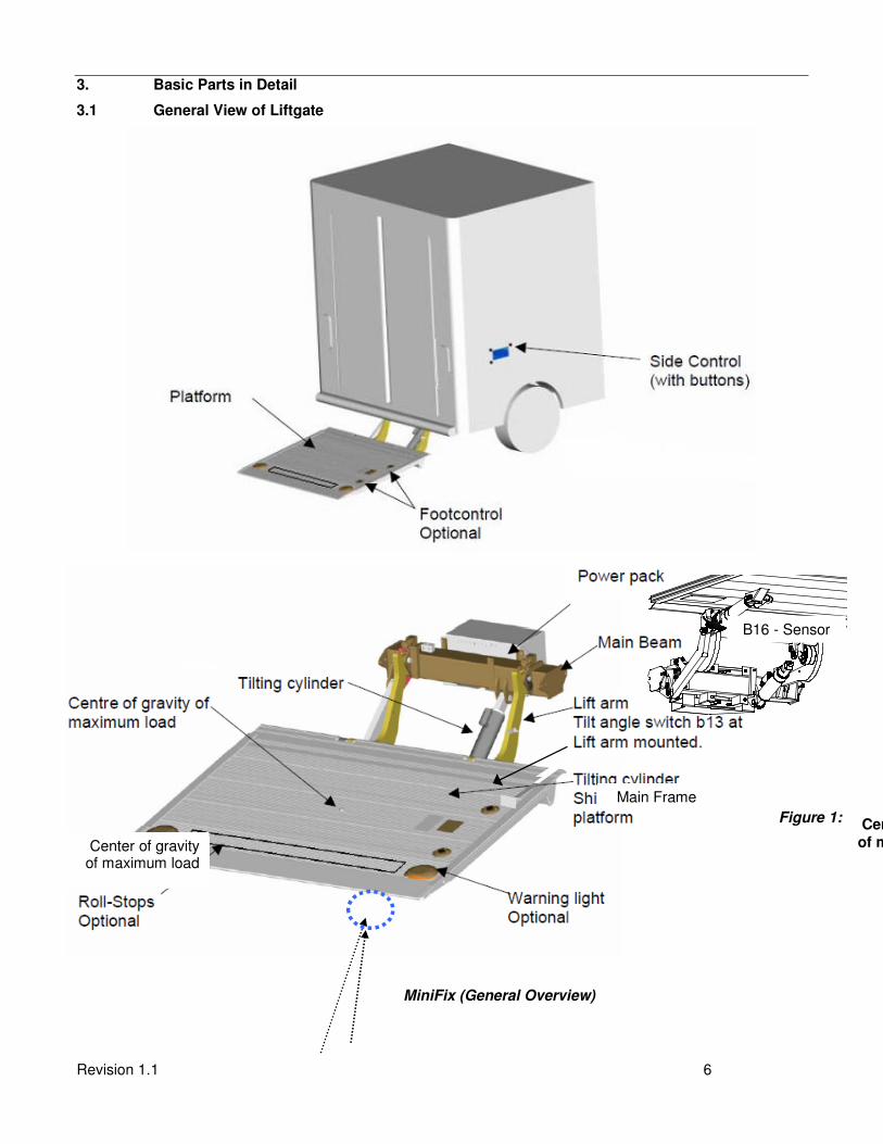
3. Basic Parts in Detail
3.1 General View of Liftgate
Figure 1:
MiniFix (General Overview)
Center of gravity of maximum load
B16 - Sensor
Center of gravity of maximum load
Main Frame

Revision 1.1 7
3.2 MiniFix Control System
3.2.1 Control System until June 2008
No. Description Part no.
3 Cable for push button P-2005 043
4 Cab on-off switch P-1332 494
5 Sensor B13 for lift arm - 2 wire P-1404 177
6 Sensor B16 for platform - 3 wire P-1404 176
7 2 foot control button with harness P-1404 178
8 Cable for solenoid valve P-67254198
9 PC board - earlier style P-1407 378
10 Foot control button P-1405 256
11 Contact block for tilt function P-67487729
12 Button with cap P-67476085
13 Plate, operation P-2005 348
14 Contact block for lift function P-67487710

Revision 1.1 8
3.2.2 Control System since July 2008
No. Description Part no.
5 Cable for power pack P-2016 594
6 Cable for power P-2016 384
12 Cover with hinge P-2007 474
13 Sensor B13 for lift arm - 3 wire P-1332 476
14 Sensor B16 for platform - 4 wire P-2015 796
15 Cable for solenoid valve P-67254198
16 Cable for platform P-2008 918
17 Cable VDHH P-2007 050
18 Cable no.9 P-2007 490
19 Cable for control box P-2020 049
21 Clamp for cover P-2010 169
22 Foot control with 2 wire P-1330 945
23 Foot control button P-1405 256
24 PC-Board - K plus P-2015 340
Revision 1.1 9
A = Distance from Truck Body to the Center
Point of Load on the Platform A
Q
Truck or Trailer
Body Q = Weight
Load diagram
10
20
30
40
50
60
70
80
90
100
0 12 24 36 48 60 72 84
distance from body (inch)
cap
acit
y (
%)
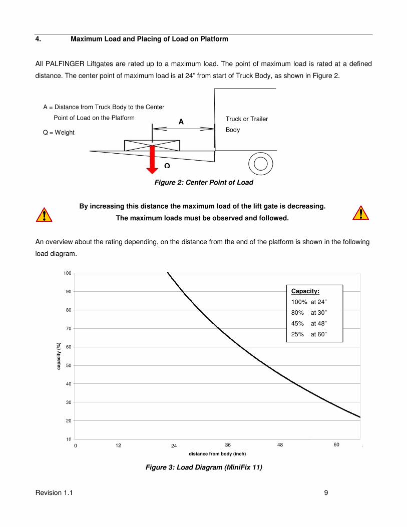
4. Maximum Load and Placing of Load on Platform
All PALFINGER Liftgates are rated up to a maximum load. The point of maximum load is rated at a defined
distance. The center point of maximum load is at 24” from start of Truck Body, as shown in Figure 2.
Figure 2: Center Point of Load
By increasing this distance the maximum load of the lift gate is decreasing.
The maximum loads must be observed and followed.
An overview about the rating depending, on the distance from the end of the platform is shown in the following
load diagram.
Figure 3: Load Diagram (MiniFix 11)
Capacity:
100% at 24”
80% at 30”
45% at 48”
25% at 60”
36 48 60 24 12 0
Revision 1.1 10
5. Operation of Liftgate
Before use: Turn Control power to “ON”, the L.E.D.’s will light up inside the cab. All liftgate functions can
be controlled with the 3-button outside control, which is mounted on the curb side of the
vehicle.
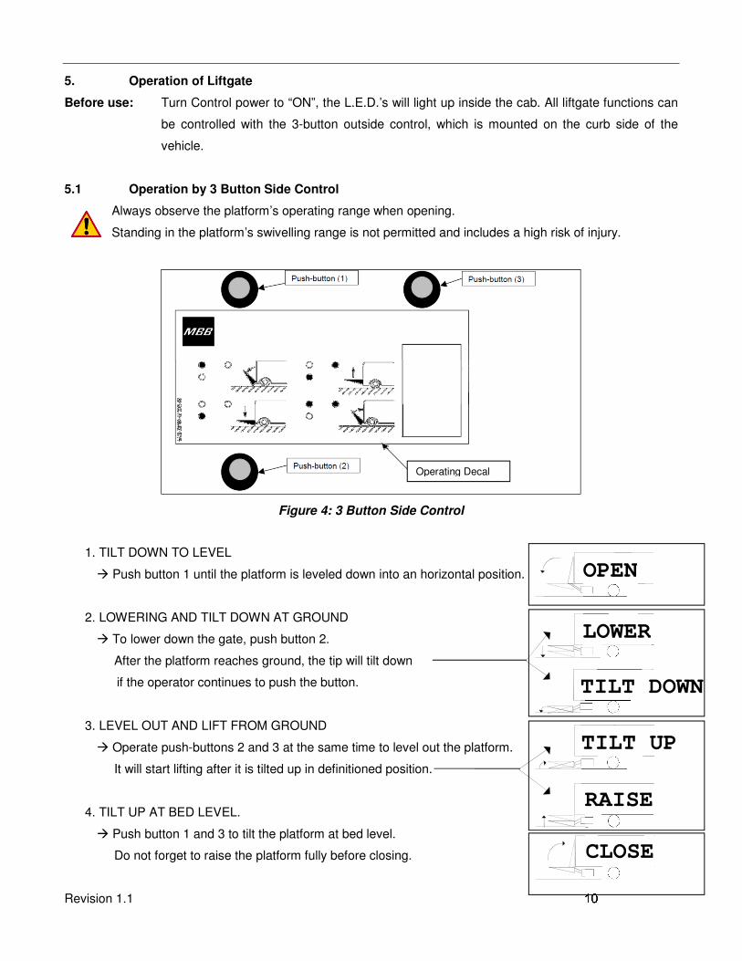
5.1 Operation by 3 Button Side Control
Always observe the platform’s operating range when opening.
Standing in the platform’s swivelling range is not permitted and includes a high risk of injury.
Figure 4: 3 Button Side Control
1. TILT DOWN TO LEVEL
� Push button 1 until the platform is leveled down into an horizontal position.
2. LOWERING AND TILT DOWN AT GROUND
� To lower down the gate, push button 2.
After the platform reaches ground, the tip will tilt down
if the operator continues to push the button.
3. LEVEL OUT AND LIFT FROM GROUND
� Operate push-buttons 2 and 3 at the same time to level out the platform.
It will start lifting after it is tilted up in definitioned position.
4. TILT UP AT BED LEVEL.
� Push button 1 and 3 to tilt the platform at bed level.
Do not forget to raise the platform fully before closing.
OPEN
LOWER
TILT DOWN
TILT UP
RAISE
CLOSE
Operating Decal

Revision 1.1 11
Revision 1.1 12
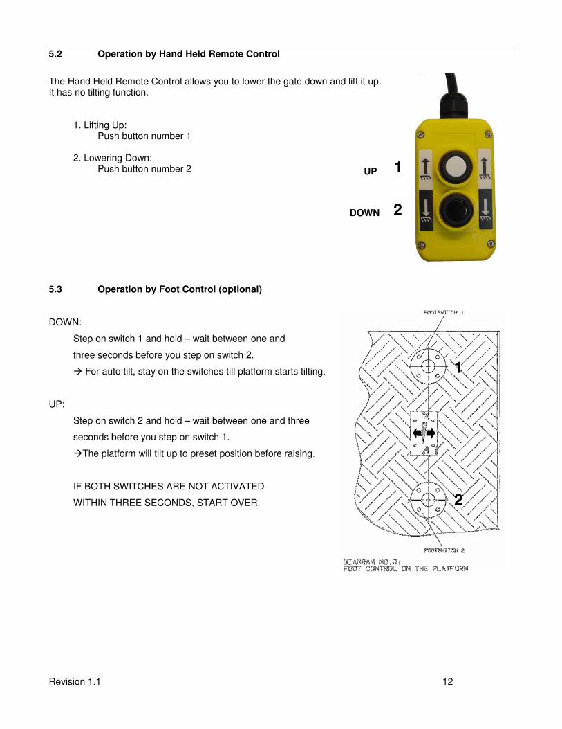
5.2 Operation by Hand Held Remote Control
The Hand Held Remote Control allows you to lower the gate down and lift it up. It has no tilting function. 1. Lifting Up: Push button number 1 2. Lowering Down: Push button number 2
5.3 Operation by Foot Control (optional)
DOWN:
Step on switch 1 and hold – wait between one and
three seconds before you step on switch 2.
� For auto tilt, stay on the switches till platform starts tilting.
UP:
Step on switch 2 and hold – wait between one and three
seconds before you step on switch 1.
�The platform will tilt up to preset position before raising.
IF BOTH SWITCHES ARE NOT ACTIVATED
WITHIN THREE SECONDS, START OVER.
UP 1
1
2
DOWN 2
Revision 1.1 13
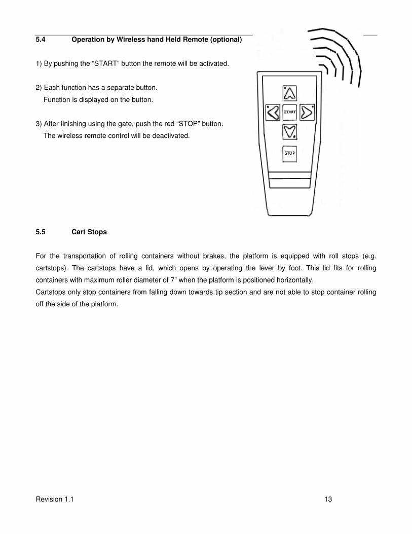
5.4 Operation by Wireless hand Held Remote (optional)
1) By pushing the “START” button the remote will be activated.
2) Each function has a separate button.
Function is displayed on the button.
3) After finishing using the gate, push the red “STOP” button.
The wireless remote control will be deactivated.
5.5 Cart Stops
For the transportation of rolling containers without brakes, the platform is equipped with roll stops (e.g.
cartstops). The cartstops have a lid, which opens by operating the lever by foot. This lid fits for rolling
containers with maximum roller diameter of 7” when the platform is positioned horizontally.
Cartstops only stop containers from falling down towards tip section and are not able to stop container rolling
off the side of the platform.

Revision 1.1 14
6. Preventive Maintenance and Quick Check
The MiniFix needs preventive maintenance to perform at its fullest capacity. Lubricate and inspect regularly.
Also check that all details are damaged: Hoses, cables, controls, etc.
REPAIR OR REPLACE IMMEDIATELY FAULTY PARTS
6.1 Maintenance and Care
The following “inspection and maintenance” should be performed at the recommended intervals depending on
operation and amount of cycles or at the time when the unit shows any signs of damage or abuse. Remember
that the secret to a long life of your PALFINGER Liftgate is to maintain it through preventive care.
* Recommended bases for
inspection and maintenance
Depending
on use Daily Monthly Quarterly
cleaning x
general lubrication of pins and
bushings x
oil level inspection x
oil change x
check hydraulic hoses and pipes for
leaks x
check controls and connections x
check pins and pin retaining bolts x
check batteries and connections x
check warning labels and other safety
equipment for effectiveness and
visibility
x
visual check for loose or missing parts
and un-usual noise during operation x
check lock bolts and pins for tightness x
check complete function of gate x
check mounting brackets of lift gate to
frame for cracks or damage visually x
Table 1: Maintenance Schedule
All parts except the chrome-coated piston rods, the push buttons, solenoids valves, foot controls and warning
lights can be cleaned by means of a water jet.
Revision 1.1 15
6.2 Lubrication
Properly lubricated, the PALFINGER Liftgates MiniFix liftgate will ensure longevity. Therefore, lubricate the lift
at the same time as the truck. Grease more frequently if the liftgate is heavily used. The liftgate should be
greased every 1200 cycles (depending on use – estimated every 3 month).
Check the oil level in the tank. The level should be 2” off the top when the platform is tilted down at ground
level. Use a good quality of hydraulic fluid, ISO 32. Change oil at least once a year, preferably in the fall before
the weather gets cold. The operation of the lift gate will accumulate condensation and some dirt which can
interfere with the lift gate functions.
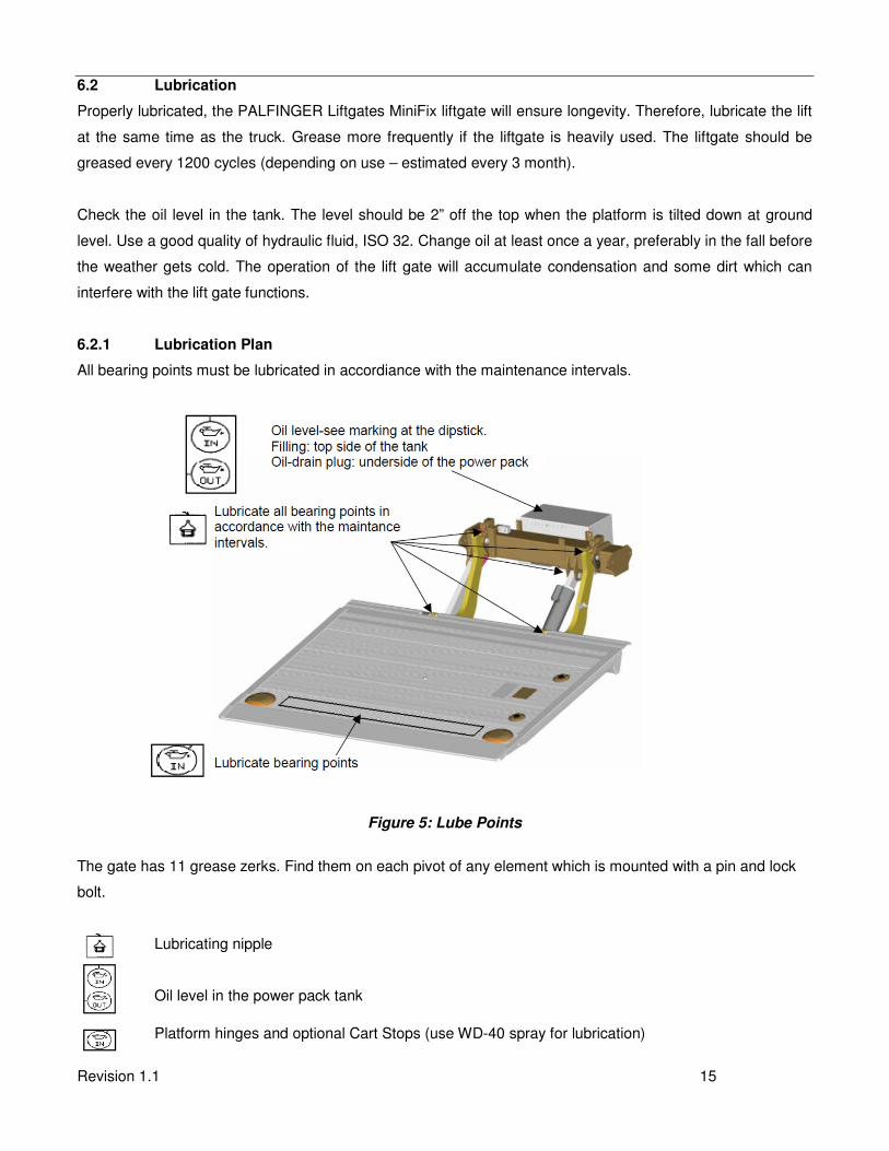
6.2.1 Lubrication Plan
All bearing points must be lubricated in accordiance with the maintenance intervals.
Figure 5: Lube Points
The gate has 11 grease zerks. Find them on each pivot of any element which is mounted with a pin and lock
bolt.
Lubricating nipple
Oil level in the power pack tank
Platform hinges and optional Cart Stops (use WD-40 spray for lubrication)

Revision 1.1 16
6.2.2 Checking and Changing the Oil
Check the quality of hydraulic fluid. If bad, take the following steps to change the oil. To begin, lower gate to
ground and tilt platform down. Open the power pack, so you can reach the oil filler cap. Unscrew the oil
drainage bolt (bottom of tray) and let the fluid drain out of the reservoir into an approved container.
If the reservoir is empty fill it up with recommended hydraulic oil, as shown on table 2. The oil level must be
within the marked limits at the oil tank or dipstick (see indication at oil tank or dipstick).
After filling, the liftgate must be opened and the oil level topped up if necessary.
Figure 6: Power Pack (Simplified View)
6.2.3 Recommended Hydraulic Fluids
TEMP. RANGE BRAND
-10 TO 150 F EXXON UNIVIS J26
MOBIL OIL DTE 13M
CHEVRON AW MV32
ROSEMEAD MV 150 (32)
-50 TO 150 F MOBIL DTE 13M
SHELL AERO FLUID 4
EXTREME COLD TEMPERATURE: USE MILITARY SPEC: MIL H5606
Table 2: Recommended Hydraulic Fluids
Revision 1.1 17
6.3 Quick Check List
1. Operate the lift gate throughout its entire operation and check for noise and damage such as bent parts or cracked welds.
2. Inspect all welds and fasteners that attach the mount frame to the truck. All pins and bolts that connect the lift arm to the mount frame and to the platform.
3. Visually inspect the hydraulic lines for damage, scratches, bending or leakage.
4. Inspect the cylinders for leakage and that the cylinder pins are secured with lock bolts.
5. Check the oil level when the platform is down at ground level. The level should fall between the markings on the tank. We recommend replacing oil after the first 1200 cycles, after that on a yearly basis in the fall before winter begins.
6. Check for oil leakage around the power pack and inside mount tube. Tighten or replace components if needed. If you perform work on any hydraulic components bleed the air out of the system by operating all functions several times.
7. Check all electrical connections. Clean and protect battery terminals and check for tightness.
8. Inspect all the terminals on the solenoid-operated valves at the port of the cylinder. Lubricate the terminals for better protection from oxidation if needed.
9. Grease all zerks on the lift gate and make sure they all take grease. Sometimes it helps to operate the lift gate while you do this.
10. Test all the lift gate functions, if possible with maximum loads placed according to load diagrams.
11. Check the function of the pressure relief valve.
12. When doing daily checks and you find any kind of damage that can make the use of the liftgate dangerous, it must be repaired before using. All repairs should be made by an authorized technician. Use only original spare parts. If in doubt contact your PALFINGER Liftgates distributor or call PALFINGER Liftgates directly.
Do not cover up any accidents or damage; it can be dangerous for you and your co-
workers.
Revision 1.1 18
7. Troubleshooting
ATTENTION:
Dangerous injuries possible from tools short circuiting main battery connections.
Please check the following points before looking for faults:
• Please change oil after working on hydraulic unit (removal of valves, opening of cylinder etc.)
• There is a possibility of injury if somebody other than an authorized technician works on the
electrical system!
• Injuries are possible if short circuits are caused by tools on the main battery connections.
7.1 Basic Function Check
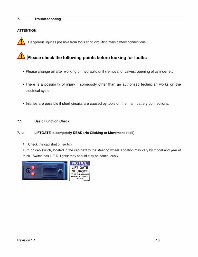
7.1.1 LIFTGATE is competely DEAD (No Clicking or Movement at all)
1. Check the cab shut off switch.
Turn on cab switch, located in the cab next to the steering wheel. Location may vary by model and year of
truck. Switch has L.E.D. lights: they should stay on continuously.

Revision 1.1 19
2. Check the circuit breaker at the main batteries.
Every truck has a circuit breaker on top of the main battery. If equiped, or a trailer, you will also find an
auxiliary battery kit as shown in the pictures below (“Truck Battery” and “Auxiliary Battery”).
If circuit breaker reset arm is popped out, push it back in as shown on the decal ATG-BKR next to your
breaker or on battery box lid.
3. Are the vehicle batteries charged?
Check batteries and the truck charging system. Start truck and run engine in fast idle for charging the
batteries. If liftgate starts working, recharge batteries.
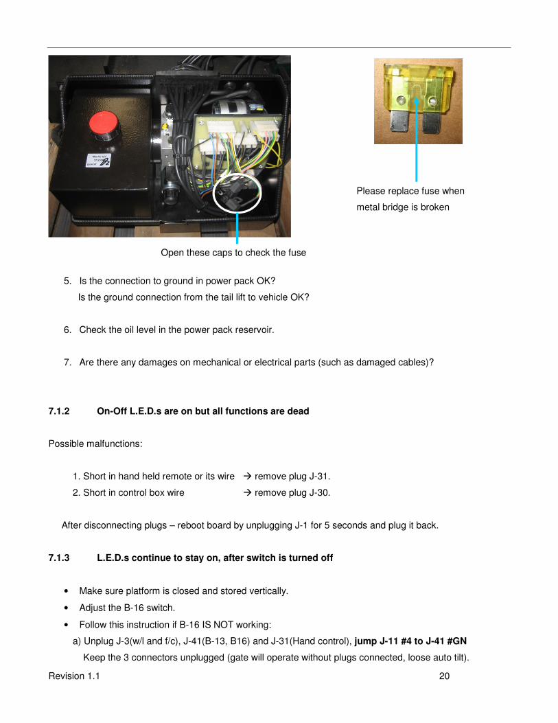
4. Check the fuse in the power pack.
In the Hydraulic Power Unit next to the motor you will find 2 fuses. Check for burned fuse and replace it
with the same type.
DO NOT use higher amperage fuse.
Truck Battery Auxiliary Battery
Location of
circuit breaker
Replace fuse when
Reset your Circuit Breaker
Revision 1.1 20
5. Is the connection to ground in power pack OK?
Is the ground connection from the tail lift to vehicle OK?
6. Check the oil level in the power pack reservoir.
7. Are there any damages on mechanical or electrical parts (such as damaged cables)?
7.1.2 On-Off L.E.D.s are on but all functions are dead
Possible malfunctions:
1. Short in hand held remote or its wire � remove plug J-31.
2. Short in control box wire � remove plug J-30.
After disconnecting plugs – reboot board by unplugging J-1 for 5 seconds and plug it back.
7.1.3 L.E.D.s continue to stay on, after switch is turned off
• Make sure platform is closed and stored vertically.
• Adjust the B-16 switch.
• Follow this instruction if B-16 IS NOT working:
a) Unplug J-3(w/l and f/c), J-41(B-13, B16) and J-31(Hand control), jump J-11 #4 to J-41 #GN
Keep the 3 connectors unplugged (gate will operate without plugs connected, loose auto tilt).
Open these caps to check the fuse
Please replace fuse when
metal bridge is broken
Revision 1.1 21
b) Unplug J-1 (Main power), wait 10 seconds and plug J-1 back to the board (Reset the board).
c) Plug each connector back, one at a time and check functions of gate after plugging in each.
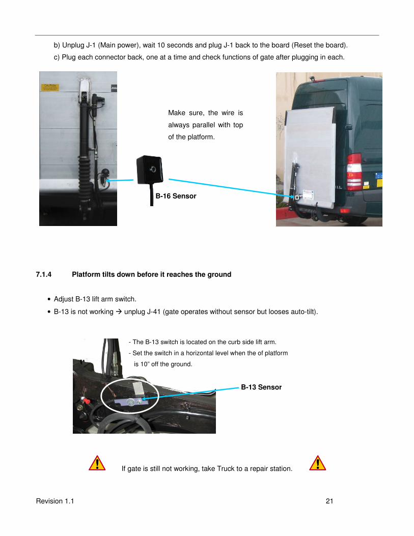
7.1.4 Platform tilts down before it reaches the ground
• Adjust B-13 lift arm switch.
• B-13 is not working � unplug J-41 (gate operates without sensor but looses auto-tilt).
If gate is still not working, take Truck to a repair station.
B-16 Sensor
Make sure, the wire is
always parallel with top
of the platform.
- The B-13 switch is located on the curb side lift arm.
- Set the switch in a horizontal level when the of platform
is 10” off the ground.
B-13 Sensor
Revision 1.1 22
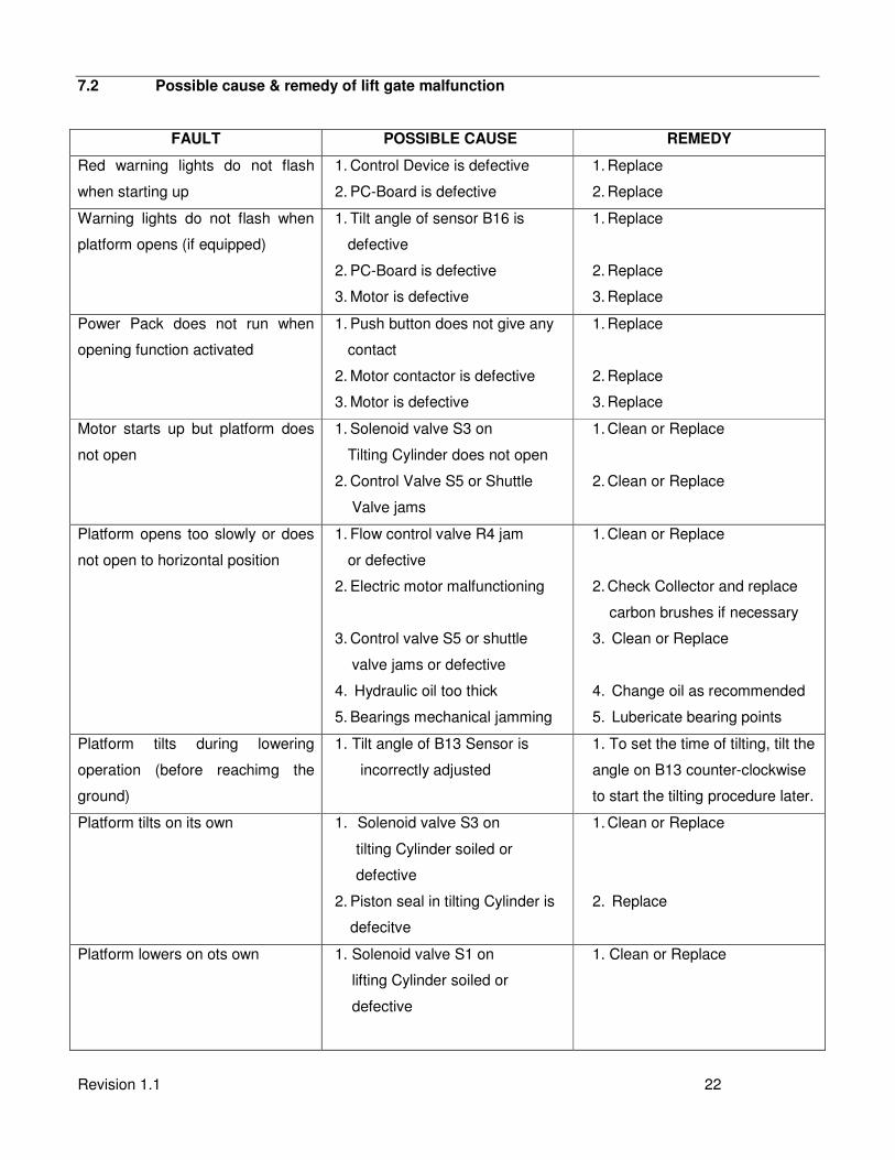
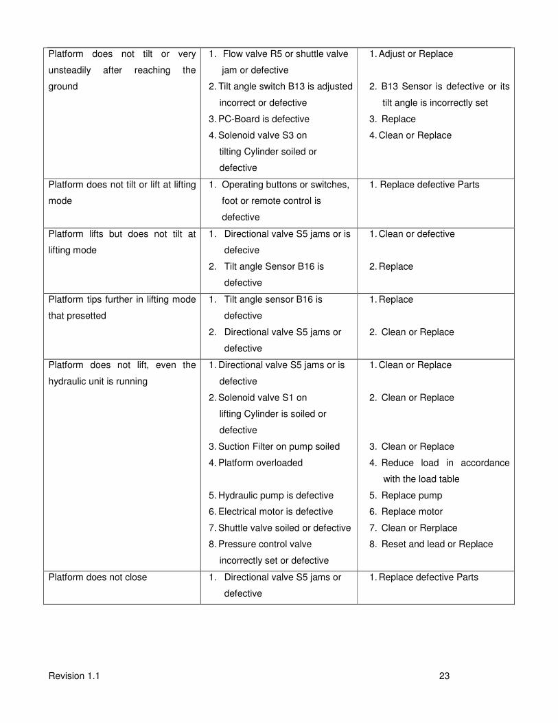
7.2 Possible cause & remedy of lift gate malfunction
FAULT POSSIBLE CAUSE REMEDY
Red warning lights do not flash
when starting up
1. Control Device is defective
2. PC-Board is defective
1. Replace
2. Replace
Warning lights do not flash when
platform opens (if equipped)
1. Tilt angle of sensor B16 is
defective
2. PC-Board is defective
3. Motor is defective
1. Replace
2. Replace
3. Replace
Power Pack does not run when
opening function activated
1. Push button does not give any
contact
2. Motor contactor is defective
3. Motor is defective
1. Replace
2. Replace
3. Replace
Motor starts up but platform does
not open
1. Solenoid valve S3 on
Tilting Cylinder does not open
2. Control Valve S5 or Shuttle
Valve jams
1. Clean or Replace
2. Clean or Replace
Platform opens too slowly or does
not open to horizontal position
1. Flow control valve R4 jam
or defective
2. Electric motor malfunctioning
3. Control valve S5 or shuttle
valve jams or defective
4. Hydraulic oil too thick
5. Bearings mechanical jamming
1. Clean or Replace
2. Check Collector and replace
carbon brushes if necessary
3. Clean or Replace
4. Change oil as recommended
5. Lubericate bearing points
Platform tilts during lowering
operation (before reachimg the
ground)
1. Tilt angle of B13 Sensor is
incorrectly adjusted
1. To set the time of tilting, tilt the
angle on B13 counter-clockwise
to start the tilting procedure later.
Platform tilts on its own 1. Solenoid valve S3 on
tilting Cylinder soiled or
defective
2. Piston seal in tilting Cylinder is
defecitve
1. Clean or Replace
2. Replace
Platform lowers on ots own 1. Solenoid valve S1 on
lifting Cylinder soiled or
defective
1. Clean or Replace
Revision 1.1 23
Platform does not tilt or very
unsteadily after reaching the
ground
1. Flow valve R5 or shuttle valve
jam or defective
2. Tilt angle switch B13 is adjusted
incorrect or defective
3. PC-Board is defective
4. Solenoid valve S3 on
tilting Cylinder soiled or
defective
1. Adjust or Replace
2. B13 Sensor is defective or its
tilt angle is incorrectly set
3. Replace
4. Clean or Replace
Platform does not tilt or lift at lifting
mode
1. Operating buttons or switches,
foot or remote control is
defective
1. Replace defective Parts
Platform lifts but does not tilt at
lifting mode
1. Directional valve S5 jams or is
defecive
2. Tilt angle Sensor B16 is
defective
1. Clean or defective
2. Replace
Platform tips further in lifting mode
that presetted
1. Tilt angle sensor B16 is
defective
2. Directional valve S5 jams or
defective
1. Replace
2. Clean or Replace
Platform does not lift, even the
hydraulic unit is running
1. Directional valve S5 jams or is
defective
2. Solenoid valve S1 on
lifting Cylinder is soiled or
defective
3. Suction Filter on pump soiled
4. Platform overloaded
5. Hydraulic pump is defective
6. Electrical motor is defective
7. Shuttle valve soiled or defective
8. Pressure control valve
incorrectly set or defective
1. Clean or Replace
2. Clean or Replace
3. Clean or Replace
4. Reduce load in accordance
with the load table
5. Replace pump
6. Replace motor
7. Clean or Rerplace
8. Reset and lead or Replace
Platform does not close 1. Directional valve S5 jams or
defective
1. Replace defective Parts
Revision 1.1 24
7.3 Electrical and Hydraulic Schematic
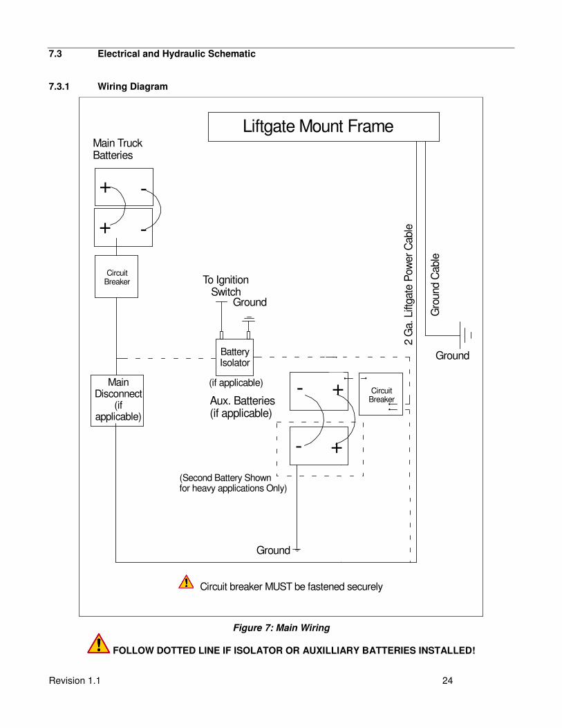
7.3.1 Wiring Diagram
Circuit breaker MUST be fastened securely
Gro
und C
able
Ground
(Second Battery Shownfor heavy applications Only)
+-
Liftgate Mount FrameMain Truck Batteries
2 G
a. Lift
gate
Pow
er
Cable
Ground
+-
+ -
To Ignition Switch
Ground
Aux. Batteries (if applicable)
BatteryIsolator
+ -
(if applicable)
CircuitBreaker
MainDisconnect
(ifapplicable)
CircuitBreaker
- -
--
Figure 7: Main Wiring
FOLLOW DOTTED LINE IF ISOLATOR OR AUXILLIARY BATTERIES INSTALLED!
Revision 1.1 25
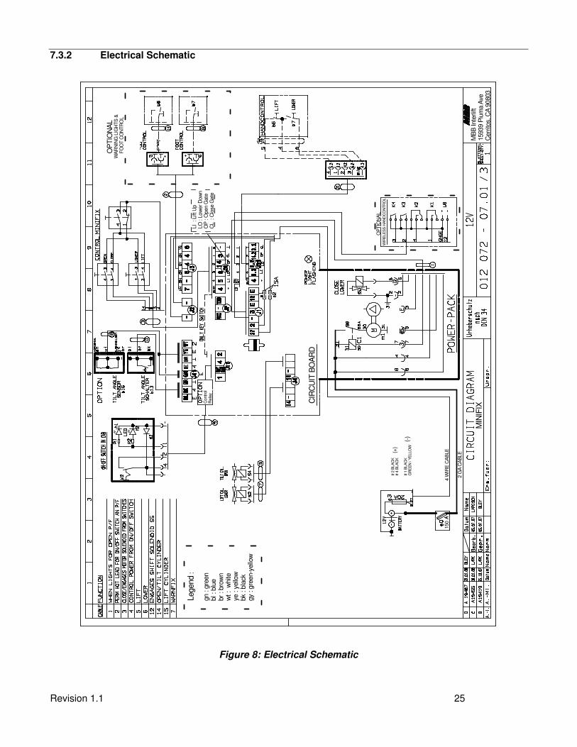
7.3.2 Electrical Schematic
MIN
IFIX
150
WIR
ELE
SS
HA
ND
CO
NT
RO
L
OP
TIO
NA
L
O
PT
ION
AL
WA
RN
ING
LIG
HT
S &
F
OO
T C
ON
TR
OL
4 W
IRE
CA
BLE
2 G
A C
AB
LE
# 2
BLA
CK
# 4
BLA
CK
# 1
BLA
CK
GR
EE
N / Y
ELLO
W
(+)
(-)
LI : L
ift U
pLO
: L
ow
er
Dow
nO
P : O
pen G
ate
CL
: C
lose
Gate
CIR
CU
IT B
OA
RD
Legend
:
gn : g
reen
bl :
blu
ebr
: bro
wn
wt : w
hite
ye : y
ello
wbk
: bla
ckgy
: gre
en-y
ello
w
MB
B Inte
rlift
15939 P
ium
a A
veC
err
itos,
CA
90803
Control
Rela
y
Figure 8: Electrical Schematic
Revision 1.1 26
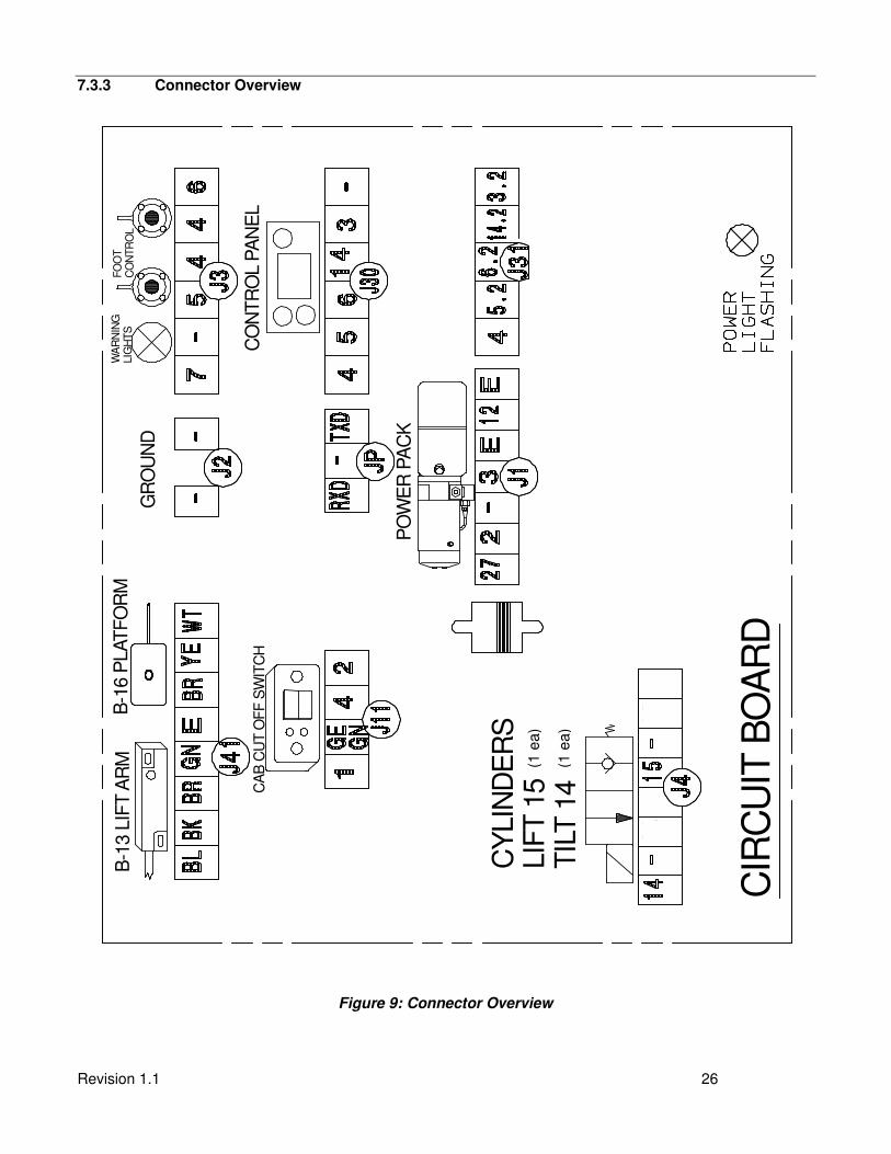
7.3.3 Connector Overview
CIR
CU
IT B
OA
RD
PO
WE
R P
AC
K
B-1
3 L
IFT A
RM
B-1
6 P
LAT
FO
RM
GR
OU
ND
CO
NT
RO
L P
AN
EL
CA
B C
UT O
FF
SW
ITC
H
FO
OT
CO
NT
RO
L
WA
RN
ING
LIG
HT
S
CY
LIN
DE
RS
LIF
T 1
5 (
2 e
a)
TIL
T 1
4 (
2ea)
Figure 9: Connector Overview
(1 e
a)
(1 e
a)
Revision 1.1 27
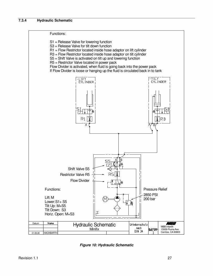
7.3.4 Hydraulic Schematic
Functions:
Lift: MLower: S1+ S5Tilt Up: M+S5Tilt Down: S3Horiz. Open: M+S3
Pressure Relief
2850 PSI200 bar
Shift Valve S5
Restrictor Valve R5
Flow Divider
Functions:
S1 = Release Valve for lowering functionS3 = Release Valve for tilt down functionR1 = Flow Restrictor located inside hose adaptor on lift cylinderR3 = Flow Restrictor located inside hose adaptor on tilt cylinderS5 = Shift Valve is activated on tilt up and lowering functionR5 = Restrictor Valve located in power packFlow Divider is activated, when fluid is going back into the power packIf Flow Divider is loose or hanging up the fluid is circulated back in to tank
3
3
Datum
01.08.08
Hydraulic Schematic
HACKBARTH
MinifixMBB Interlift15939 Piuma AveCerritos, CA 90803
Figure 10: Hydraulic Schematic
Revision 1.1 28
8. Needed Information for Ordering Spare Parts and Repairs
8.1 Ordering Spare Parts
In order to assure quick delivery of spare parts, please always state the following information when making
orders:
1. Lliftgate model & serial number.
2. Designation and number of the spare part in accordance with the spare parts list.
3. Designation and number marked on the individual component (if available).
8.2 Repairs
Parts sent to PALFINGER Liftgates to repair must be accompanied by a letter (in separate cover) giving
details and scope of the repairs required.
Revision 1.1 29
9. Warranty
PALFINGER Liftgates provides warranty as part of its conditions of delivery.
Spare part deliveries are first of all billed. PALFINGER Liftgates then issues credit for all or part of the invoiced
sum, when PALFINGER Liftgates has been able to determine that the warranty claim is justified as defined by
its warranty conditions. PALFINGER Liftgates does this by inspecting the defected parts which are sent back
to PALFINGER Liftgates freight-prepaid as well as the written description of the problem which must have
been filled out in full.
The parts that are sent back to PALFINGER Liftgates, marked with serial number and address, become
PALFINGER Liftgates’ property if the warranty claim is accepted.
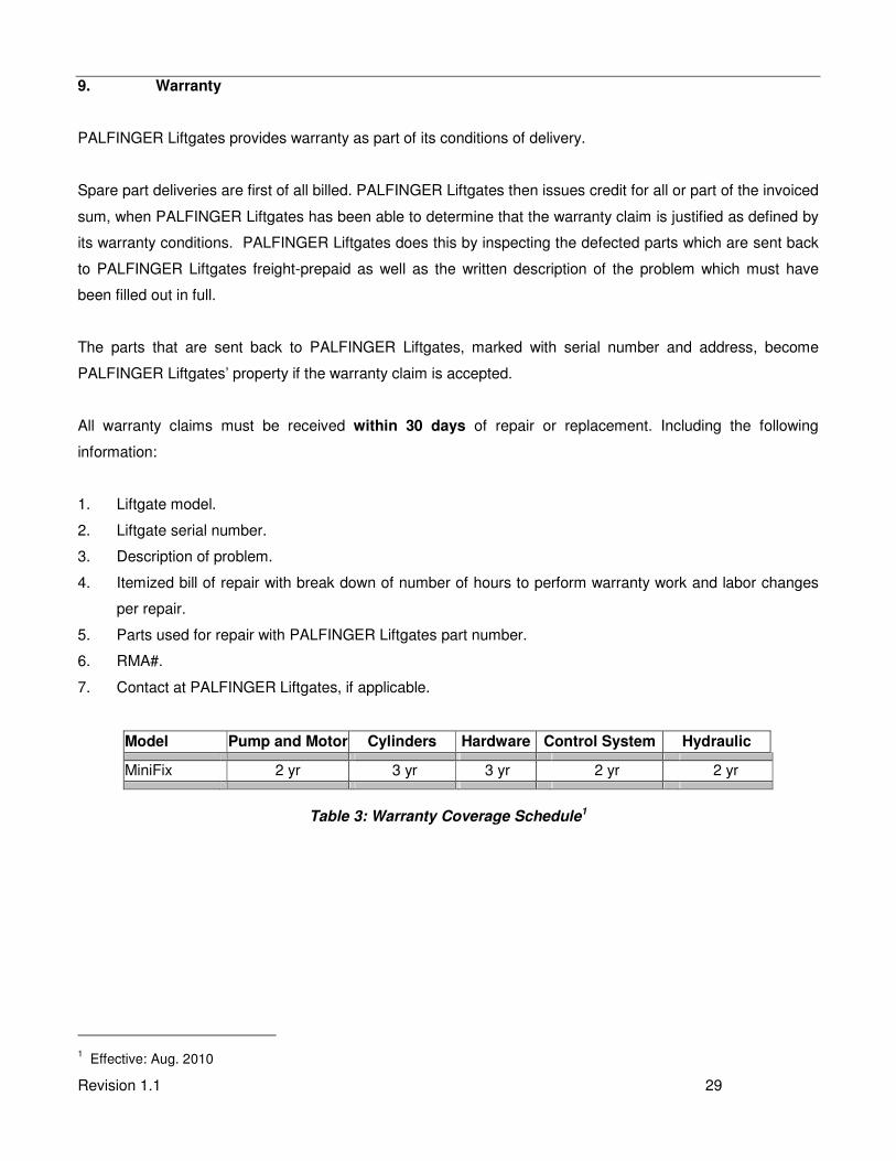
All warranty claims must be received within 30 days of repair or replacement. Including the following
information:
1. Liftgate model.
2. Liftgate serial number.
3. Description of problem.
4. Itemized bill of repair with break down of number of hours to perform warranty work and labor changes
per repair.
5. Parts used for repair with PALFINGER Liftgates part number.
6. RMA#.
7. Contact at PALFINGER Liftgates, if applicable.
Model Pump and Motor Cylinders Hardware Control System Hydraulic
MiniFix 2 yr 3 yr 3 yr 2 yr 2 yr
Table 3: Warranty Coverage Schedule1
1 Effective: Aug. 2010
Revision 1.1 30
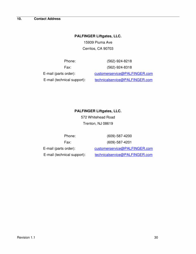
10. Contact Address
PALFINGER Liftgates, LLC.
15939 Piuma Ave
Cerritos, CA 90703
Phone: (562)-924-8218
Fax: (562)-924-8318
E-mail (parts order): [email protected]
E-mail (technical support): [email protected]
PALFINGER Liftgates, LLC.
572 Whitehead Road
Trenton, NJ 08619
Phone: (609)-587-4200
Fax: (609)-587-4201
E-mail (parts order): [email protected]
E-mail (technical support): [email protected]