Embed Size (px)
Citation preview
RESEARCH REPORT 1405-5
INTERIM CONCLUSIONS, RECOMMENDATIONS, AND DESIGN GUIDELINES FOR DURABILITY OF
POST-TENSIONED BRIDGE SUBSTRUCTURES A. J. Schokker, J. S. West, J. E. Breen, and M. E. Kreger
CENTER FOR TRANSPORTATION RESEARCH BUREAU OF ENGINEERING RESEARCH THE UNIVERSITY OF TEXAS AT AUSTIN O C T O B E R 1 9 9 9
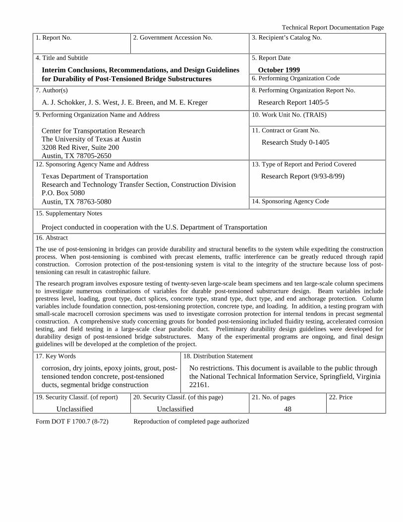
Technical Report Documentation Page
1. Report No.
2. Government Accession No. 3. Recipient’s Catalog No.
4. Title and Subtitle
Interim Conclusions, Recommendations, and Design Guidelines
5. Report Date
October 1999 for Durability of Post-Tensioned Bridge Substructures 6. Performing Organization Code
7. Author(s) 8. Performing Organization Report No.
A. J. Schokker, J. S. West, J. E. Breen, and M. E. Kreger Research Report 1405-5
9. Performing Organization Name and Address 10. Work Unit No. (TRAIS)
Center for Transportation Research The University of Texas at Austin 3208 Red River, Suite 200 Austin, TX 78705-2650
11. Contract or Grant No.
Research Study 0-1405
12. Sponsoring Agency Name and Address
Texas Department of Transportation Research and Technology Transfer Section, Construction Division P.O. Box 5080
13. Type of Report and Period Covered
Research Report (9/93-8/99)
Austin, TX 78763-5080 14. Sponsoring Agency Code
15. Supplementary Notes
Project conducted in cooperation with the U.S. Department of Transportation
16. Abstract
The use of post-tensioning in bridges can provide durability and structural benefits to the system while expediting the construction process. When post-tensioning is combined with precast elements, traffic interference can be greatly reduced through rapid construction. Corrosion protection of the post-tensioning system is vital to the integrity of the structure because loss of post-tensioning can result in catastrophic failure.
The research program involves exposure testing of twenty-seven large-scale beam specimens and ten large-scale column specimens to investigate numerous combinations of variables for durable post-tensioned substructure design. Beam variables include prestress level, loading, grout type, duct splices, concrete type, strand type, duct type, and end anchorage protection. Column variables include foundation connection, post-tensioning protection, concrete type, and loading. In addition, a testing program with small-scale macrocell corrosion specimens was used to investigate corrosion protection for internal tendons in precast segmental construction. A comprehensive study concerning grouts for bonded post-tensioning included fluidity testing, accelerated corrosion testing, and field testing in a large-scale clear parabolic duct. Preliminary durability design guidelines were developed for durability design of post-tensioned bridge substructures. Many of the experimental programs are ongoing, and final design guidelines will be developed at the completion of the project.
17. Key Words
corrosion, dry joints, epoxy joints, grout, post-tensioned tendon concrete, post-tensioned ducts, segmental bridge construction
18. Distribution Statement
No restrictions. This document is available to the public through the National Technical Information Service, Springfield, Virginia 22161.
19. Security Classif. (of report)
Unclassified
20. Security Classif. (of this page)
Unclassified
21. No. of pages
48
22. Price
Form DOT F 1700.7 (8-72) Reproduction of completed page authorized
INTERIM CONCLUSIONS, RECOMMENDATIONS, AND
DESIGN GUIDELINES FOR DURABILITY OF POST-TENSIONED BRIDGE SUBSTRUCTURES
by
A. J. Schokker, J. S. West, J. E. Breen, and M. E. Kreger
Research Report 1405-5
Research Project 0-1405
DURABILITY DESIGN OF POST-TENSIONED BRIDGE SUBSTRUCTURE ELEMENTS
conducted for the
Texas Department of Transportation
In cooperation with the
U.S. Department of Transportation Federal Highway Administration
by the
CENTER FOR TRANSPORTATION RESEARCH BUREAU OF ENGINEERING RESEARCH
THE UNIVERSITY OF TEXAS AT AUSTIN
October 1999

iv
Research performed in cooperation with the Texas Department of Transportation and the U.S. Department of Transportation, Federal Highway Administration.
ACKNOWLEDGMENTS We greatly appreciate the financial support from the Texas Department of Transportation that made this project possible. The support of the project director, Bryan Hodges (BRG), and program coordinator, Richard Wilkison (BRG), is also very much appreciated. We thank Project Monitoring Committee members, Gerald Lankes (CST), Ronnie VanPelt (BMT), and Tamer Ahmed (FHWA). We would also like to thank FHWA personnel, Jim Craig, Susan Lane, and Bob Stanford, for their assistance on this project.
DISCLAIMER
The contents of this report reflect the views of the authors, who are responsible for the facts and the accuracy of the data presented herein. The contents do not necessarily reflect the view of the Federal Highway Administration or the Texas Department of Transportation. This report does not constitute a standard, specification, or regulation.
NOT INTENDED FOR CONSTRUCTION, PERMIT, OR BIDDING PURPOSES
J.E. Breen, P.E., TX #18479 M.E. Kreger, P.E., TX #65541
Research Supervisors
v
TABLE OF CONTENTS
CHAPTER 1: INTRODUCTION................................................................................................ 1
1.1 Bridge Substructure Durability ........................................................................................................1
1.2 Post-Tensioning in Bridge Substructures .........................................................................................2
1.2.1 Benefits of Post-Tensioning ................................................................................................................. 2 1.3 Mixed Reinforcement in Structural Concrete ..................................................................................5
1.4 Problem Statement ...........................................................................................................................6
1.5 Research Objectives and Project Scope ...........................................................................................7
1.5.1 Project Objectives ................................................................................................................................ 7
1.5.2 Project Scope ....................................................................................................................................... 7
CHAPTER 2: DURABILITY DESIGN GUIDELINES ......................................................... 11
2.1 Introduction ....................................................................................................................................11
2.2 Assessing the Environmental Exposure Condition ........................................................................13
2.3 Assessing the Severity of Durability Attack ..................................................................................13
2.3.1 Severity of Environmental Conditions for Freeze-Thaw Damage ..................................................... 13
2.3.2 Severity of Environmental Conditions for Sulfate Attack................................................................... 14
2.3.3 Severity of Environmental Conditions for Corrosion......................................................................... 14
2.4 Assessing the Substructure Component Exposure Condition ........................................................16
2.4.1 Susceptibility of Substructure Components to Freeze-Thaw Damage ............................................... 16 2.4.2 Susceptibility of Substructure Components to Sulfate Attack............................................................. 17 2.4.3 Susceptibility of Substructure Components to Reinforcement Corrosion .......................................... 19
2.5 Establishing the Required Level of Protection for Durability........................................................21
2.6 Protection Measures for Durable Structures ..................................................................................22
2.6.1 Protection Measures for Freeze-Thaw Damage ................................................................................ 22 2.6.2 Protection Measures for Sulfate Attack ............................................................................................. 23 2.6.3 Protection Measures for Reinforcement Corrosion ........................................................................... 23
2.7 Durability Design Procedure..........................................................................................................28
CHAPTER 3: PROJECT SUMMARY AND CONCLUSIONS ............................................ 29
3.1 Grout ..............................................................................................................................................29
3.1.1 Fresh Property Tests.......................................................................................................................... 29 3.1.2 Accelerated Corrosion Tests .............................................................................................................. 29 3.1.3 Large-Scale Duct Tests ...................................................................................................................... 29
3.2 Beams and Columns.......................................................................................................................30
3.2.1 Large-Scale Beam Specimens ............................................................................................................ 30 3.2.2 Large-Scale Column Specimens......................................................................................................... 32
3.3 Macrocells ......................................................................................................................................33
vi
3.3.1 Overall Performance ......................................................................................................................... 33 3.3.2 Assessing Corrosion Activity Using Half-Cell Potential Measurements ........................................... 33 3.3.3 Segmental Joints ................................................................................................................................ 33 3.3.4 Ducts for Internal Post-Tensioning.................................................................................................... 34 3.3.5 Joint Precompression......................................................................................................................... 34 3.3.6 Grouts for Bonded Post-Tensioning................................................................................................... 34
CHAPTER 4: IMPLEMENTATION RECOMMENDATIONS ........................................... 35
4.1 Grout ..............................................................................................................................................35
Item 1: Post-Tensioned Tendons with Small Rises ...................................................................................... 35
Item 2: Post-Tensioned Tendons with Large Rises ...................................................................................... 35
Item 3: Grouting Procedures and Specifications......................................................................................... 35
4.2 Beams and Columns.......................................................................................................................35
Item 1: Post-Tensioning............................................................................................................................... 35
Item 2: Plastic Duct ..................................................................................................................................... 35
Item 3: Plastic Chairs.................................................................................................................................. 36
Item 4: Fly Ash Concrete ............................................................................................................................. 36
Item 5: High-Performance Concrete ........................................................................................................... 36
4.3 Macrocells ......................................................................................................................................36
Item 1: Joint Type – Internal Prestressing .................................................................................................. 36
Item 2: Joint Type – External Prestressing.................................................................................................. 36
Item 3: Gaskets around Duct Openings....................................................................................................... 36
Item 4: Plastic Duct ..................................................................................................................................... 36
Item 5: Corrosion Inhibitor in Grouts ......................................................................................................... 36
References.............................................................................................................................................37
vii
LIST OF FIGURES Figure 1.1 Typical Corrosion Damage in Texas Bridge Substructures.......................................................1
Figure 1.2 ASCE Evaluation of Infrastruture Condition.............................................................................2
Figure 1.3 Multilevel Corrosion Protection for Bonded Post-Tensioning Tendons ...................................3
Figure 1.4 Post-Tensioned Precast Segmental Bridge Pier.........................................................................4
Figure 1.5 Precast Bridge Pier Segment Close-Up .....................................................................................4
Figure 1.6 Precast Bridge Pier Segments ....................................................................................................5
Figure 1.7 Post-Tensioned Straddle Bent....................................................................................................5
Figure 2.1 Simplified Analogy Between Design for Structural Loading and Durability..........................12
Figure 2.2 Global Substructure Exposure Conditions for Bridges in Texas .............................................13
Figure 2.3 Environmental Freeze-Thaw Damage Severity Ratings..........................................................14
Figure 2.4 Environmental Corrosion Severity Ratings for Freezing Exposures Where Chloride-Based Deicing Chemicals are Used.........................................................................................15
Figure 2.5 Substructure Exposure Zones and Forms of Deterioration in Coastal Seawater Exposures....19
viii
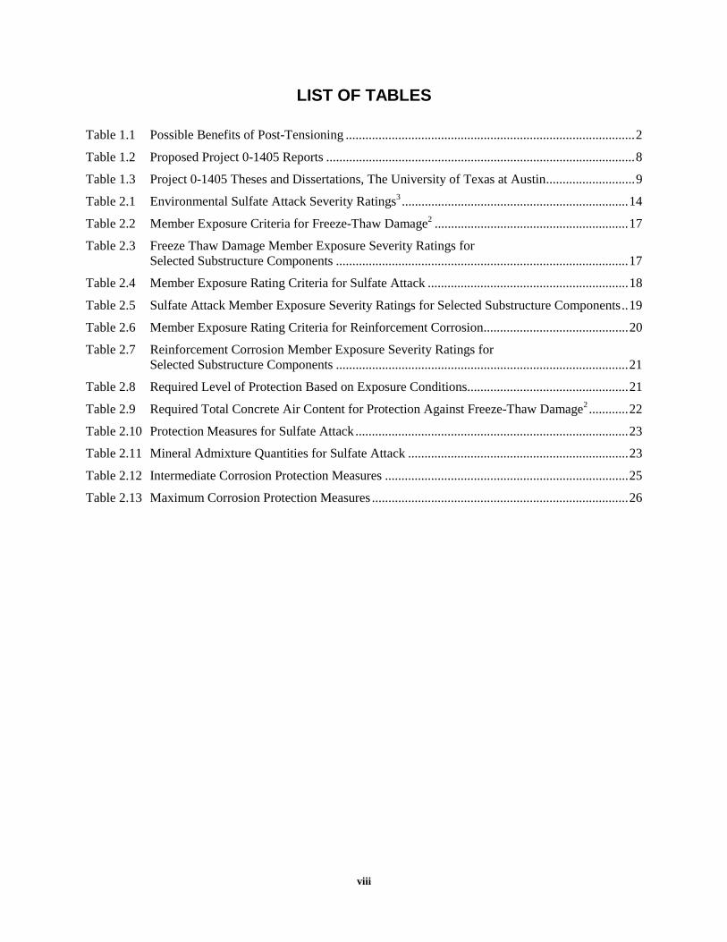
LIST OF TABLES
Table 1.1 Possible Benefits of Post-Tensioning ........................................................................................2
Table 1.2 Proposed Project 0-1405 Reports ..............................................................................................8
Table 1.3 Project 0-1405 Theses and Dissertations, The University of Texas at Austin...........................9
Table 2.1 Environmental Sulfate Attack Severity Ratings3 .....................................................................14
Table 2.2 Member Exposure Criteria for Freeze-Thaw Damage2 ...........................................................17
Table 2.3 Freeze Thaw Damage Member Exposure Severity Ratings for Selected Substructure Components .........................................................................................17
Table 2.4 Member Exposure Rating Criteria for Sulfate Attack .............................................................18
Table 2.5 Sulfate Attack Member Exposure Severity Ratings for Selected Substructure Components..19
Table 2.6 Member Exposure Rating Criteria for Reinforcement Corrosion............................................20
Table 2.7 Reinforcement Corrosion Member Exposure Severity Ratings for Selected Substructure Components .........................................................................................21
Table 2.8 Required Level of Protection Based on Exposure Conditions.................................................21
Table 2.9 Required Total Concrete Air Content for Protection Against Freeze-Thaw Damage2 ............22
Table 2.10 Protection Measures for Sulfate Attack ...................................................................................23
Table 2.11 Mineral Admixture Quantities for Sulfate Attack ...................................................................23
Table 2.12 Intermediate Corrosion Protection Measures ..........................................................................25
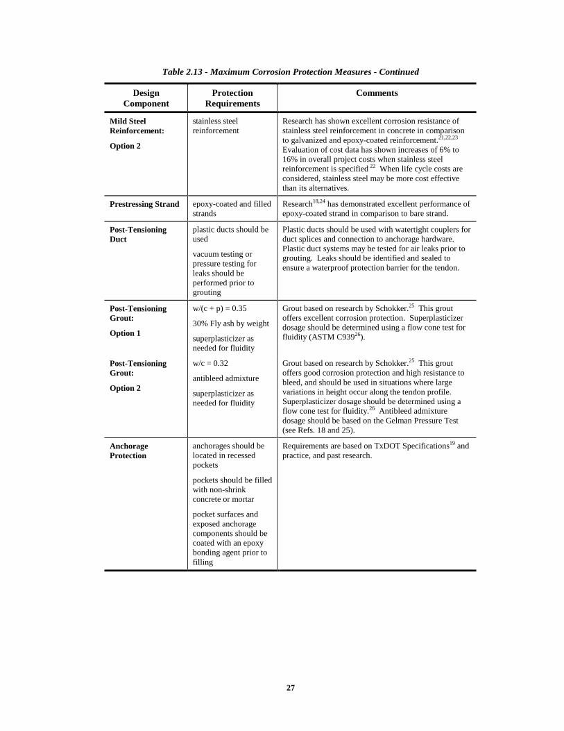
Table 2.13 Maximum Corrosion Protection Measures ..............................................................................26
ix
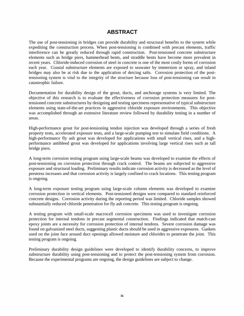
ABSTRACT The use of post-tensioning in bridges can provide durability and structural benefits to the system while expediting the construction process. When post-tensioning is combined with precast elements, traffic interference can be greatly reduced through rapid construction. Post-tensioned concrete substructure elements such as bridge piers, hammerhead bents, and straddle bents have become more prevalent in recent years. Chloride-induced corrosion of steel in concrete is one of the most costly forms of corrosion each year. Coastal substructure elements are exposed to seawater by immersion or spray, and inland bridges may also be at risk due to the application of deicing salts. Corrosion protection of the post-tensioning system is vital to the integrity of the structure because loss of post-tensioning can result in catastrophic failure. Documentation for durability design of the grout, ducts, and anchorage systems is very limited. The objective of this research is to evaluate the effectiveness of corrosion protection measures for post-tensioned concrete substructures by designing and testing specimens representative of typical substructure elements using state-of-the-art practices in aggressive chloride exposure environments. This objective was accomplished through an extensive literature review followed by durability testing in a number of areas. High-performance grout for post-tensioning tendon injection was developed through a series of fresh property tests, accelerated exposure tests, and a large-scale pumping test to simulate field conditions. A high-performance fly ash grout was developed for applications with small vertical rises, and a high-performance antibleed grout was developed for applications involving large vertical rises such as tall bridge piers. A long-term corrosion testing program using large-scale beams was developed to examine the effects of post-tensioning on corrosion protection through crack control. The beams are subjected to aggressive exposure and structural loading. Preliminary results indicate corrosion activity is decreased as the level of prestress increases and that corrosion activity is largely confined to crack locations. This testing program is ongoing. A long-term exposure testing program using large-scale column elements was developed to examine corrosion protection in vertical elements. Post-tensioned designs were compared to standard reinforced concrete designs. Corrosion activity during the reporting period was limited. Chloride samples showed substantially reduced chloride penetration for fly ash concrete. This testing program is ongoing. A testing program with small-scale macrocell corrosion specimens was used to investigate corrosion protection for internal tendons in precast segmental construction. Findings indicated that match-cast epoxy joints are a necessity for corrosion protection of internal tendons. Severe corrosion damage was found on galvanized steel ducts, suggesting plastic ducts should be used in aggressive exposures. Gaskets used on the joint face around duct openings allowed moisture and chlorides to penetrate the joint. This testing program is ongoing. Preliminary durability design guidelines were developed to identify durability concerns, to improve substructure durability using post-tensioning and to protect the post-tensioning system from corrosion. Because the experimental programs are ongoing, the design guidelines are subject to change.

1
CHAPTER 1 INTRODUCTION
1.1 BRIDGE SUBSTRUCTURE DURABILITY
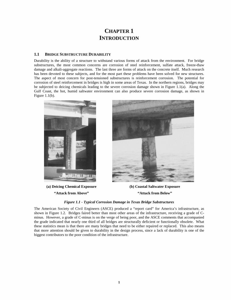
Durability is the ability of a structure to withstand various forms of attack from the environment. For bridge substructures, the most common concerns are corrosion of steel reinforcement, sulfate attack, freeze-thaw damage and alkali-aggregate reactions. The last three are forms of attack on the concrete itself. Much research has been devoted to these subjects, and for the most part these problems have been solved for new structures. The aspect of most concern for post-tensioned substructures is reinforcement corrosion. The potential for corrosion of steel reinforcement in bridges is high in some areas of Texas. In the northern regions, bridges may be subjected to deicing chemicals leading to the severe corrosion damage shown in Figure 1.1(a). Along the Gulf Coast, the hot, humid saltwater environment can also produce severe corrosion damage, as shown in Figure 1.1(b).
(a) Deicing Chemical Exposure (b) Coastal Saltwater Exposure
“Attack from Above” “Attack from Below”
Figure 1.1 - Typical Corrosion Damage in Texas Bridge Substructures
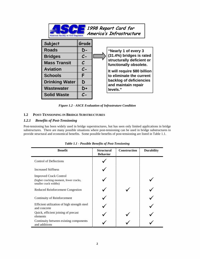
The American Society of Civil Engineers (ASCE) produced a “report card” for America’s infrastructure, as shown in Figure 1.2. Bridges faired better than most other areas of the infrastructure, receiving a grade of C-minus. However, a grade of C-minus is on the verge of being poor, and the ASCE comments that accompanied the grade indicated that nearly one third of all bridges are structurally deficient or functionally obsolete. What these statistics mean is that there are many bridges that need to be either repaired or replaced. This also means that more attention should be given to durability in the design process, since a lack of durability is one of the biggest contributors to the poor condition of the infrastructure.
2
������������ ���������������������
RoadsBridgesMass TransitAviationSchoolsDrinking WaterWastewaterSolid Waste
�������������
����� ���“Nearly 1 of every 3(31.4%) bridges is ratedstructurally deficient orfunctionally obsolete.
It will require $80 billionto eliminate the currentbacklog of deficienciesand maintain repairlevels.”
Figure 1.2 - ASCE Evaluation of Infrastruture Condition
1.2 POST-TENSIONING IN BRIDGE SUBSTRUCTURES
1.2.1 Benefits of Post-Tensioning
Post-tensioning has been widely used in bridge superstructures, but has seen only limited applications in bridge substructures. There are many possible situations where post-tensioning can be used in bridge substructures to provide structural and economical benefits. Some possible benefits of post-tensioning are listed in Table 1.1.
Table 1.1 - Possible Benefits of Post-Tensioning
Benefit Structural Behavior
Construction Durability
Control of Deflections �
Increased Stiffness � Improved Crack Control (higher cracking moment, fewer cracks, smaller crack widths)
� � Reduced Reinforcement Congestion � � � Continuity of Reinforcement � � Efficient utilization of high strength steel and concrete � � Quick, efficient joining of precast elements � � � Continuity between existing components and additions � � �

3
Although prestressing or post-tensioning is normally chosen for structural or construction reasons, many of the same factors can improve durability. For example, reduced cracking and crack widths offer the potential for improving the corrosion protection provided by the concrete. Reduced reinforcement congestion and continuity of reinforcement mean that it is easier to place and compact the concrete with less opportunity for voids in the concrete. Post-tensioning is often used in conjunction with precasting. Precast concrete offers improved quality control, concrete quality and curing conditions, all leading to improved corrosion protection. Bonded post-tensioning also provides the opportunity for multiple levels of corrosion protection for the prestressing tendon, as shown in Figure 1.3. Protection measures include surface treatments on the concrete, the concrete itself, the duct, the grout and strand or bar coatings such as epoxy or galvanizing. Post-tensioning also provides the opportunity to electrically isolate the prestressing system from the rest of the structure.
duct
coated strand
grout
moisture, chlorides, CO2
concrete
surface treatment
Figure 1.3 - Multilevel Corrosion Protection for Bonded Post-Tensioning Tendons
Although the concept of post-tensioning is not new, post-tensioning as it stands today is a relatively new form of construction, having been used in bridge structures in the United States for a little over forty-five years. At this stage in development, construction practices and materials are continuously improving. It is important that durability of the structure be considered during this development process. In particular, chloride-induced corrosion is a very real concern for all types of bridges. Research in this area for post-tensioned bridges is limited in part due to the long-term nature of durability studies.
The development of new post-tensioning materials and systems in recent years has made some of the durability research in this area obsolete. The current research focuses on durability testing of many different state-of-the-art variables for post-tensioning, focusing on substructure elements. A combination of electrically accelerated corrosion tests and exposure tests with varying degrees of severity is used to provide results in a timely manner.
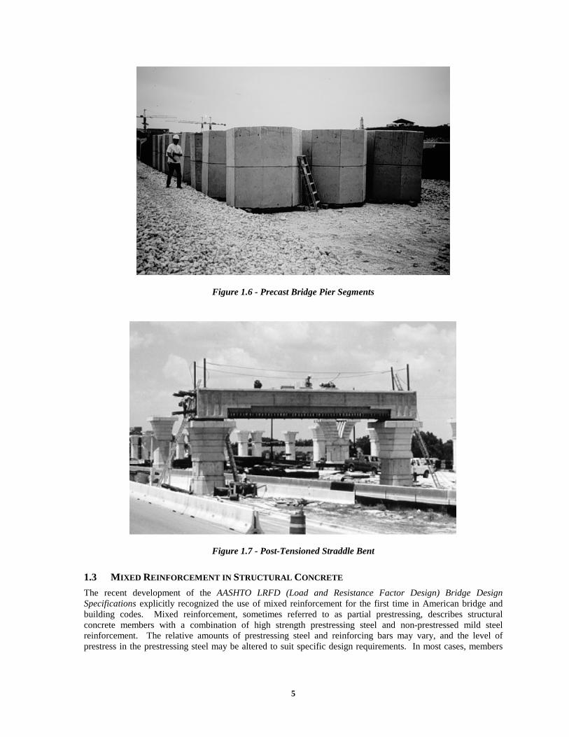
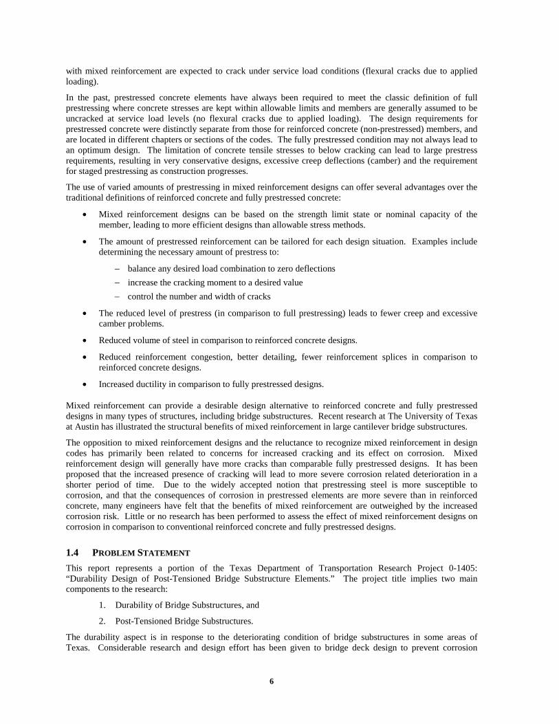
Post-tensioned bridge substructures are becoming a more prevalent form of construction. The utilization of precast, post-tensioned substructure elements can significantly reduce traffic inference, and can be particularly beneficial in large urban areas. The substructure elements also have the potential to be aesthetically pleasing alternatives as shown in Figure 1.4. This figure shows a post-tensioned precast segmental bridge pier from U.S. Highway 183 in Austin, Texas prior to addition of the superstructure. The precast components that make up this pier are shown in Figure 1.5 and 1.6. The post-tensioning ducts are evident in the close-up in Figure 1.5. A post-tensioned straddle bent from this project is shown in Figure 1.7.

4
Figure 1.4 - Post-Tensioned Precast Segmental Bridge Pier
Figure 1.5 - Precast Bridge Pier Segment Close-Up
5
Figure 1.6 - Precast Bridge Pier Segments
Figure 1.7 - Post-Tensioned Straddle Bent
1.3 MIXED REINFORCEMENT IN STRUCTURAL CONCRETE
The recent development of the AASHTO LRFD (Load and Resistance Factor Design) Bridge Design Specifications explicitly recognized the use of mixed reinforcement for the first time in American bridge and building codes. Mixed reinforcement, sometimes referred to as partial prestressing, describes structural concrete members with a combination of high strength prestressing steel and non-prestressed mild steel reinforcement. The relative amounts of prestressing steel and reinforcing bars may vary, and the level of prestress in the prestressing steel may be altered to suit specific design requirements. In most cases, members
6
with mixed reinforcement are expected to crack under service load conditions (flexural cracks due to applied loading).
In the past, prestressed concrete elements have always been required to meet the classic definition of full prestressing where concrete stresses are kept within allowable limits and members are generally assumed to be uncracked at service load levels (no flexural cracks due to applied loading). The design requirements for prestressed concrete were distinctly separate from those for reinforced concrete (non-prestressed) members, and are located in different chapters or sections of the codes. The fully prestressed condition may not always lead to an optimum design. The limitation of concrete tensile stresses to below cracking can lead to large prestress requirements, resulting in very conservative designs, excessive creep deflections (camber) and the requirement for staged prestressing as construction progresses.
The use of varied amounts of prestressing in mixed reinforcement designs can offer several advantages over the traditional definitions of reinforced concrete and fully prestressed concrete:
• Mixed reinforcement designs can be based on the strength limit state or nominal capacity of the member, leading to more efficient designs than allowable stress methods.
• The amount of prestressed reinforcement can be tailored for each design situation. Examples include determining the necessary amount of prestress to:
− balance any desired load combination to zero deflections
− increase the cracking moment to a desired value
− control the number and width of cracks
• The reduced level of prestress (in comparison to full prestressing) leads to fewer creep and excessive camber problems.
• Reduced volume of steel in comparison to reinforced concrete designs.
• Reduced reinforcement congestion, better detailing, fewer reinforcement splices in comparison to reinforced concrete designs.
• Increased ductility in comparison to fully prestressed designs.
Mixed reinforcement can provide a desirable design alternative to reinforced concrete and fully prestressed designs in many types of structures, including bridge substructures. Recent research at The University of Texas at Austin has illustrated the structural benefits of mixed reinforcement in large cantilever bridge substructures.
The opposition to mixed reinforcement designs and the reluctance to recognize mixed reinforcement in design codes has primarily been related to concerns for increased cracking and its effect on corrosion. Mixed reinforcement design will generally have more cracks than comparable fully prestressed designs. It has been proposed that the increased presence of cracking will lead to more severe corrosion related deterioration in a shorter period of time. Due to the widely accepted notion that prestressing steel is more susceptible to corrosion, and that the consequences of corrosion in prestressed elements are more severe than in reinforced concrete, many engineers have felt that the benefits of mixed reinforcement are outweighed by the increased corrosion risk. Little or no research has been performed to assess the effect of mixed reinforcement designs on corrosion in comparison to conventional reinforced concrete and fully prestressed designs.
1.4 PROBLEM STATEMENT
This report represents a portion of the Texas Department of Transportation Research Project 0-1405: “Durability Design of Post-Tensioned Bridge Substructure Elements.” The project title implies two main components to the research:
1. Durability of Bridge Substructures, and
2. Post-Tensioned Bridge Substructures.
The durability aspect is in response to the deteriorating condition of bridge substructures in some areas of Texas. Considerable research and design effort has been given to bridge deck design to prevent corrosion
7
damage, while substructures have been largely overlooked. In some districts of the state, more than ten percent of the substructures are deficient, and the substructure condition is limiting the service life of the bridges.
The second aspect of the research is post-tensioned substructures. As described above, there are many possible applications in bridge substructures where post-tensioning can provide structural and economical benefits, and can possibly improve durability. Post-tensioning is now being used in Texas bridge substructures, and it is reasonable to expect the use of post-tensioning to increase in the future as precasting of substructure components becomes more prevalent and as foundation sizes increase.
Problem:
The problem that bridge engineers are faced with is that there are no durability design guidelines for post-tensioned concrete structures. Durability design guidelines should provide information on how to identify possible durability problems, how to improve durability using post-tensioning, and how to ensure that the post-tensioning system does not introduce new durability problems.
1.5 RESEARCH OBJECTIVES AND PROJECT SCOPE
1.5.1 Project Objectives
The research objectives for TxDOT Project 0-1405 are as follows:
1. To examine the use of post-tensioning in bridge substructures,
2. To identify durability concerns for bridge substructures in Texas,
3. To identify existing technology to ensure durability or improve durability,
4. To develop experimental testing programs to evaluate protection measures for improving the durability of post-tensioned bridge substructures, and
5. To develop durability design guidelines and recommendations for post-tensioned bridge substructures.
A review of literature early in the project indicated that post-tensioning was being successfully used in past and present bridge substructure designs, and that suitable post-tensioning hardware was readily available. It was decided not to develop possible post-tensioned bridge substructure designs as part of the first objective for two reasons. First, other research on post-tensioned substructures was already underway, and second, the durability issues warranted the full attention of Project 0-1405. The third objective was added after the project had begun. The initial literature review identified a substantial amount of relevant information that could be applied to the durability of post-tensioned bridge substructures. This allowed the scope of the experimental portion of the project to be narrowed. The final objective represents the culmination of the project. All of the research findings are to be compiled into the practical format of durability design guidelines.
1.5.2 Project Scope
The research presented in this report represents part of a large project funded by the Texas Department of Transportation, entitled, “Durability Design of Post-Tensioned Bridge Substructures” (Project 0-1405). Nine reports are scheduled to be developed from this project as listed in Table 1.2. A brief discussion of Reports 1405-1 through 1405-5 is provided below the table.
8
Table 1.2 - Proposed Project 0-1405 Reports
Number Title Estimated Completion
1405-1 State of the Art Durability of Post-Tensioned Bridge Substructures 1999
1405-2 Development of High-Performance Grouts for Bonded Post-Tensioned Structures
1999
1405-3 Long-term Post-Tensioned Beam and Column Exposure Test Specimens: Experimental Program
1999
1405-4 Corrosion Protection for Bonded Internal Tendons in Precast Segmental Construction
1999
1405-5 Interim Conclusions, Recommendations and Design Guidelines for Durability of Post-Tensioned Bridge Substructures
1999
1405-6 Final Evaluation of Corrosion Protection for Bonded Internal Tendons in Precast Segmental Construction
2002
1405-7 Design Guidelines for Corrosion Protection for Bonded Internal Tendons in Precast Segmental Construction
2002
1405-8 Long-term Post-Tensioned Beam and Column Exposure Test Specimens: Final Evaluation
2003
1405-9 Conclusions, Recommendations and Design Guidelines for Durability of Post-Tensioned Bridge Substructures
2003
Report 1405-1 provides a detailed background to the topic of durability design of post-tensioned bridge substructures. The report contains an extensive literature review on various aspects of the durability of post-tensioned bridge substructures and a detailed analysis of bridge substructure condition rating data in the State of Texas.
Report 1405-2 presents a detailed study of improved and high-performance grouts for bonded post-tensioned structures. Three testing phases were employed in the testing program: fresh property tests, accelerated corrosion tests and large-scale pumping tests. The testing process followed a progression of the three phases. A large number of variables were first investigated for fresh properties. Suitable mixtures then proceeded to accelerated corrosion tests. Finally, the most promising mixtures from the first two phases were tested in the large-scale pumping tests. The variables investigated included water-cement ratio, superplasticizer, antibleed admixture, expanding admixture, corrosion inhibitor, silica fume and fly ash. Two optimized grouts were recommended depending on the particular post-tensioning application.
Report 1405-3 describes the development of two long term, large-scale exposure testing programs, one with beam elements, and one with columns. A detailed discussion of the design of the test specimens and selection of variables is presented. Preliminary experimental data is presented and analyzed, including cracking behavior, chloride penetration, half-cell potential measurements and corrosion rate measurements. Preliminary conclusions are presented.
Report 1405-4 describes a series of macrocell corrosion specimens developed to examine corrosion protection for internal prestressing tendons in precast segmental bridges. This report briefly describes the test specimens and variables, and presents and discusses four and a half years of exposure test data. One-half (nineteen of thirty-eight) of the macrocell specimens were subjected to a forensic examination after four and a half years of testing. A detailed description of the autopsy process and findings is included. Conclusions based on the exposure testing and forensic examination are presented.
Report 1405-5 (this document) contains a summary of the conclusions and recommendations from the first four reports from Project 0-1405. The findings of the literature review and experimental work were used to develop preliminary durability design guidelines for post-tensioned bridge substructures. The durability design process is described, and guidance is provided for assessing the durability risk and for ensuring protection against

9
freeze-thaw damage, sulfate attack and corrosion of steel reinforcement. These guidelines will be refined and expanded in the future under Project 0-1405 as more experimental data becomes available.
Several dissertations and theses at The University of Texas at Austin were developed from the research from Project 0-1405. These documents may be valuable supplements to specific areas in the research and are listed in Table 1.3 for reference.
Table 1.3 - Project 0-1405 Theses and Dissertations, The University of Texas at Austin
Title Author
Masters Theses
“Evaluation of Cement Grouts for Strand Protection Using Accelerated Corrosion Tests” Bradley D. Koester
“Test Method for Evaluating Corrosion Mechanisms in Standard Bridge Columns” Carl J. Larosche
Ph.D. Dissertations
“Improving Corrosion Resistance of Post-Tensioned Substructures Emphasizing High-Performance Grouts”
Andrea J. Schokker
“Durability Design of Post-Tensioned Bridge Substructures” Jeffrey S. West

10
11
CHAPTER 2 DURABILITY DESIGN GUIDELINES
2.1 INTRODUCTION
Designing for durability requires the same thought process as design for any other limit state or form of structural loading. The engineer must first assess the type of loading to be considered and determine its intensity. Then, the engineer must determine the effects of the loading on the structure and design the structure to resist the loading through careful proportioning and detailing. The various components of the structure may have different design requirements depending on their function, and these requirements must be identified and addressed. A simplified analogy between durability design and design for structural loading is illustrated in Figure 2.1. Although the two processes are similar, the “precision” of design for durability can be significantly different from design for structural loading. The types and intensities of design requirements or loading can be assessed with similar accuracy in both cases. However, the resistance of the structure to durability attack can not be determined with the same level of certainty as in the estimation of the resistance of the structure to structural loading. This lack of precision is reflected in the durability design process, as will be discussed in this chapter.
Durability design guidelines should provide the engineer with the following information:
• How to determine when different forms of attack on durability should be considered.
The engineer should be able to establish when durability must be considered as a limit state in the design process and be able to identify which forms of attack will occur in a given situation. Due to the varied climate, geology and geography of Texas, durability may play a significant role in the design process for some situations, while in others it may not.
• How to evaluate the severity of attack on structural durability in a given situation.
Once it has been determined that certain forms of durability problems may occur, the possible severity of attack needs to be assessed.
• How to determine what level of protection is necessary for the various components of the structure.
The required level of protection for the structural components is a function of the forms and severity of attack that may be encountered in a particular situation. It is also strongly affected by the susceptibility of the various components of the substructure to the expected forms of attack.
• What measures can be employed to provide the necessary level of protection.
Once the required level of protection has been determined, the engineer should be presented with design options to provide the necessary level of protection for durability.

12
Design for Structural Loading Design for Durability
Types of loading (vehicular, wind, earthquake, etc.) ≡ Forms of attack on durability
(corrosion, freeze-thaw damage, etc.)
⇓ ⇓
Intensity of loading for a given structure and location ≡ Severity of attack on durability for a
given structure and location
⇓ ⇓
Analysis of the structure for the given loading ≡ Analysis of the susceptibility of the
structure and structural components to the given forms of attack
⇓ ⇓
Design requirements (forces, moments, etc.) for individual structural components ≡ Required level of durability protection for
individual structural components
⇓ ⇓
Materials selection, proportioning and detailing of structural components ≡ Materials selection, proportioning and
detailing of structural components
Figure 2.1 - Simplified Analogy Between Design for Structural Loading and Durability
The fundamental objective of durability research is to apply the research findings in the form of durability design guidelines. This is the goal of TxDOT Project 0-1405, where the final product will be durability design guidelines for post-tensioned bridge substructures. Such guidelines must provide direction on identifying situations where durability is a concern and on how to ensure durability. The guideline must address how to use post-tensioning to improve durability while protecting the post-tensioning system from becoming a durability problem itself.
The experimental durability research performed as part of Project 0-1405 is still largely underway. Many significant findings have arisen from the research to date, as described in Research Reports 1405-2, 1405-3 and 1405-4. However, continued monitoring of the testing programs and a comprehensive forensic examination of the test specimens at the completion of testing are expected to provide a wealth of additional information on the durability of post-tensioned substructures. At the present stage of Project 0-1405, the research results and findings are not sufficient to develop comprehensive durability design guidelines for post-tensioned bridge substructures. However, preliminary durability design guidelines were developed1 using the extensive literature review reported in Research Report 1404-1 and the preliminary research findings from the different testing programs. It is expected that the design guidelines will be refined and expanded as the project is completed and more information and detailed experimental results become available. The preliminary durability design guidelines for Project 0-1405 are presented in this chapter. The following subject areas are discussed:
• Assessing the environmental exposure (forms of attack) for bridges in Texas.
• Assessing the severity of attack on durability.
• Assessing the susceptibility of substructure components to attack on durability.

13
• Determining the required level of protection for durability.
• Protection measures for durable post-tensioned concrete structures.
2.2 ASSESSING THE ENVIRONMENTAL EXPOSURE CONDITION
The environmental exposure conditions at a given location dictate what forms of durability attack may occur on the structure. The substructure exposure conditions in Texas are shown in Figure 2.2. More detailed discussion of substructure exposure conditions in Texas is provided in Research Report 1405-1. This figure indicates three different exposure conditions in Texas for bridge substructures: coastal exposure, freezing exposure and sulfate soils. Depending on the type of exposure, various forms of attack may be expected to occur, as indicated in Figure 2.2. For a given bridge location, Figure 2.2 can be used to determine the forms of environmental durability problems that may be encountered.
Freezing Exposure:Corrosion &Freeze-Thaw Damage
Sulfate Soils: Sulfate Attack
Coastal Exposure:Corrosion &Sulfate Attack
FHWA"Deicing Line"
Brownwood
22-Laredo
10-Tyler
16-CorpusChristi
21-Pharr
14-Austin
11-Lufkin
17-Bryan
19-Atlanta
15-San Antonio
7-San Angelo
3-Wichita Falls
8-Abilene
5-Lubbock
4-Amarillo
18-Dallas
1-Paris
20-Beaumont
9-Waco
25-Childress
6-Odessa
24-El Paso
2-Fort Worth
12-Houston
13-Yoakum
23-
Figure 2.2 - Global Substructure Exposure Conditions for Bridges in Texas
2.3 ASSESSING THE SEVERITY OF DURABILITY ATTACK
Once it has been determined that a particular form of durability distress may occur in an environment, the severity of the attack must be established.
2.3.1 Severity of Environmental Conditions for Freeze-Thaw Damage
The severity of the Texas environment for freeze-thaw damage in bridge structures was reported by Watkins2 and discussed in Research Report 1405-1. Based on an analysis of climate data and deicing chemical usage in Texas, Watkins developed the chart shown in Figure 2.3 to assess the degree of severity of freeze-thaw damage in Texas.
14
Brownwood
22-Laredo
10-Tyler
16-CorpusChristi
21-Pharr
14-Austin
11-Lufkin
17-Bryan
19-Atlanta
15-San Antonio
7-San Angelo
3-Wichita Falls
8-Abilene
5-Lubbock
4-Amarillo
18-Dallas
1-Paris
20-Beaumont
9-Waco
25-Childress
6-Odessa
24-El Paso
2-Fort Worth
12-Houston
13-Yoakum
23-
Freeze-Thaw Conditions:
Severe
Moderate
Mild
Figure 2.3 - Environmental Freeze-Thaw Damage Severity Ratings
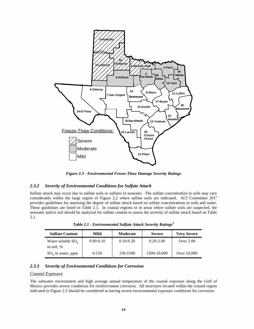
2.3.2 Severity of Environmental Conditions for Sulfate Attack
Sulfate attack may occur due to sulfate soils or sulfates in seawater. The sulfate concentration in soils may vary considerably within the large region of Figure 2.2 where sulfate soils are indicated. ACI Committee 2013 provides guidelines for assessing the degree of sulfate attack based on sulfate concentrations in soils and water. These guidelines are listed in Table 2.1. In coastal regions or in areas where sulfate soils are suspected, the seawater and/or soil should be analyzed for sulfate content to assess the severity of sulfate attack based on Table 2.1.
Table 2.1 - Environmental Sulfate Attack Severity Ratings3
Sulfate Content Mild Moderate Severe Very Severe
Water soluble SO4 in soil, %
0.00-0.10 0.10-0.20 0.20-2.00 Over 2.00
SO4 in water, ppm 0-150 150-1500 1500-10,000 Over 10,000
2.3.3 Severity of Environmental Conditions for Corrosion
Coastal Exposure
The saltwater environment and high average annual temperature of the coastal exposure along the Gulf of Mexico provides severe conditions for reinforcement corrosion. All structures located within the coastal region indicated in Figure 2.2 should be considered as having severe environmental exposure conditions for corrosion.
15
Freezing Exposure
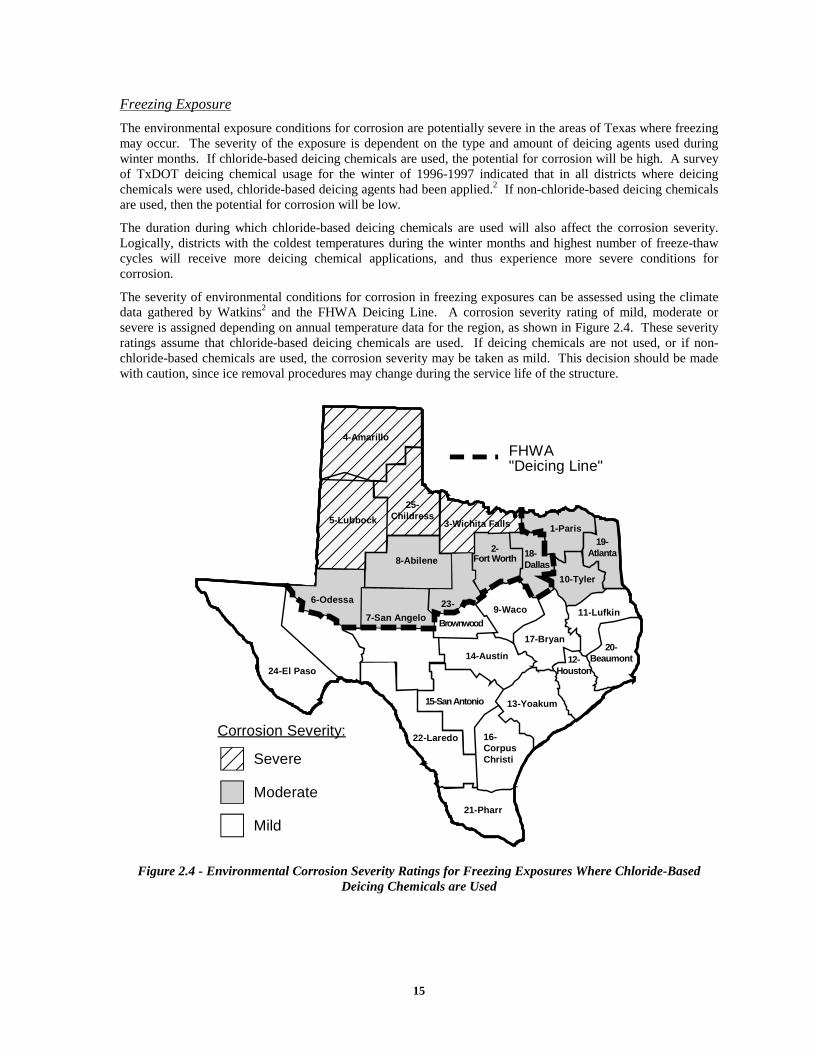
The environmental exposure conditions for corrosion are potentially severe in the areas of Texas where freezing may occur. The severity of the exposure is dependent on the type and amount of deicing agents used during winter months. If chloride-based deicing chemicals are used, the potential for corrosion will be high. A survey of TxDOT deicing chemical usage for the winter of 1996-1997 indicated that in all districts where deicing chemicals were used, chloride-based deicing agents had been applied.2 If non-chloride-based deicing chemicals are used, then the potential for corrosion will be low.
The duration during which chloride-based deicing chemicals are used will also affect the corrosion severity. Logically, districts with the coldest temperatures during the winter months and highest number of freeze-thaw cycles will receive more deicing chemical applications, and thus experience more severe conditions for corrosion.
The severity of environmental conditions for corrosion in freezing exposures can be assessed using the climate data gathered by Watkins2 and the FHWA Deicing Line. A corrosion severity rating of mild, moderate or severe is assigned depending on annual temperature data for the region, as shown in Figure 2.4. These severity ratings assume that chloride-based deicing chemicals are used. If deicing chemicals are not used, or if non-chloride-based chemicals are used, the corrosion severity may be taken as mild. This decision should be made with caution, since ice removal procedures may change during the service life of the structure.
FHWA"Deicing Line"
Brownwood
22-Laredo
10-Tyler
16-CorpusChristi
21-Pharr
14-Austin
11-Lufkin
17-Bryan
19-Atlanta
15-San Antonio
7-San Angelo
3-Wichita Falls
8-Abilene
5-Lubbock
4-Amarillo
18-Dallas
1-Paris
20-Beaumont
9-Waco
25-Childress
6-Odessa
24-El Paso
2-Fort Worth
12-Houston
13-Yoakum
23-
Corrosion Severity:
Severe
Moderate
Mild
Figure 2.4 - Environmental Corrosion Severity Ratings for Freezing Exposures Where Chloride-Based Deicing Chemicals are Used
16
2.4 ASSESSING THE SUBSTRUCTURE COMPONENT EXPOSURE CONDITION
The exposure conditions for a specific structural component can have a significant effect on the severity of attack on that element. Different components of the substructure may experience more or less severe deterioration than would be expected for a given environment. The severity of the local exposure conditions is a function of the temperature, presence of moisture, availability of oxygen and exposure to aggressive agents for a particular substructure component. A detailed discussion of bridge substructure exposure conditions is provided in Chapter 3 of Research Report 1405-1.
The significance of member exposure condition can be illustrated using examples. The direct exposure to aggressive agents plays a role in whether deterioration will occur. In a region with sulfate soils, only components directly in contact with the soils are at risk for sulfate attack. Therefore, pile caps or other foundation elements may require sulfate resistant cements and the use of mineral admixtures, but the columns and bent caps of the substructure may not. Another example occurs in areas where deicing chemicals are used. If drainage of chloride-laden moisture from the superstructure onto the substructure is prevented, the corrosion risk for the substructure will be low. However, if drainage is poor or superstructure joints leak, moisture and chlorides may contact the substructure and cause corrosion damage. Thus, the design and details of the superstructure may influence the substructure durability requirements. The availability of oxygen is a significant factor for corrosion. Substructure components that are continually submerged will experience only limited corrosion damage due to lack of oxygen. The local temperature conditions for a structural element will affect the severity of freeze-thaw damage. Elements that are buried or have one or more surfaces in contact with the ground will benefit from the insulation provided by the soil, and may experience less severe freeze-thaw damage.
2.4.1 Susceptibility of Substructure Components to Freeze-Thaw Damage
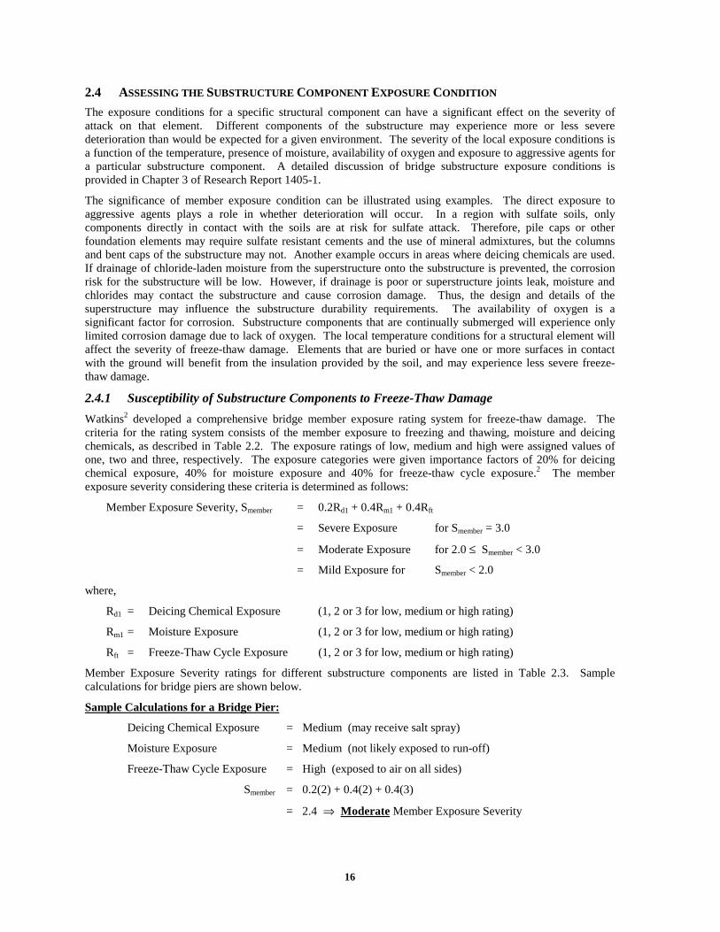
Watkins2 developed a comprehensive bridge member exposure rating system for freeze-thaw damage. The criteria for the rating system consists of the member exposure to freezing and thawing, moisture and deicing chemicals, as described in Table 2.2. The exposure ratings of low, medium and high were assigned values of one, two and three, respectively. The exposure categories were given importance factors of 20% for deicing chemical exposure, 40% for moisture exposure and 40% for freeze-thaw cycle exposure.2 The member exposure severity considering these criteria is determined as follows:
Member Exposure Severity, Smember = 0.2Rd1 + 0.4Rm1 + 0.4Rft
= Severe Exposure for Smember = 3.0
= Moderate Exposure for 2.0 ≤ Smember < 3.0
= Mild Exposure for Smember < 2.0
where,
Rd1 = Deicing Chemical Exposure (1, 2 or 3 for low, medium or high rating)
Rm1 = Moisture Exposure (1, 2 or 3 for low, medium or high rating)
Rft = Freeze-Thaw Cycle Exposure (1, 2 or 3 for low, medium or high rating)
Member Exposure Severity ratings for different substructure components are listed in Table 2.3. Sample calculations for bridge piers are shown below.
Sample Calculations for a Bridge Pier:
Deicing Chemical Exposure = Medium (may receive salt spray)
Moisture Exposure = Medium (not likely exposed to run-off)
Freeze-Thaw Cycle Exposure = High (exposed to air on all sides)
Smember = 0.2(2) + 0.4(2) + 0.4(3)
= 2.4 ⇒ Moderate Member Exposure Severity
17
Table 2.2 - Member Exposure Criteria for Freeze-Thaw Damage2
Exposure Rating
Deicing Chemical Exposure, Rd1
Moisture Exposure, Rm1 Freeze-Thaw Cycle Exposure, Rft
Low
(1)
Deicing chemicals are not used on or around this member, or member is located underground or in water insulated from deicing chemical exposure.
Members that are not likely to become critically saturated such as vertical walls or members located inside a covered structure.
Members which are insulated from freeze-thaw cycles by soil or water so that it does not freeze. Member located inside temperature controlled buildings.
Medium
(2)
Members that do not receive direct application of deicing chemicals, but may receive salt spray if deicing chemicals are used.
Water is not likely to pond on concrete surface or member will not be exposed to run-off.
Member exposed to circulating air on only one side or has thick member dimensions (> 200 mm (8 in.)).
High
(3)
Horizontal concrete surfaces which receive direct application of deicing chemicals or are likely to be in contact with water that contains deicing chemicals, or members located directly below open bridge expansion joints.
Member on which water is likely to pond or member which receives frequent direct contact with drainage or run-off water.
Member exposed to air circulation on more than one side or members with thin dimensions (> 200 mm (8 in.)).
Table 2.3 - Freeze-Thaw Damage Member Exposure Severity Ratings for Selected Substructure Components
Member Exposure Substructure Component
Mild Exposure
• Drilled Shafts
• Prestressed Piling
• Abutments
• Buried Pile Caps
Moderate Exposure
• Bridge Piers
• Columns
• Drilled Shafts in Water
• Exposed Pile Caps
Severe Exposure • Bent Caps
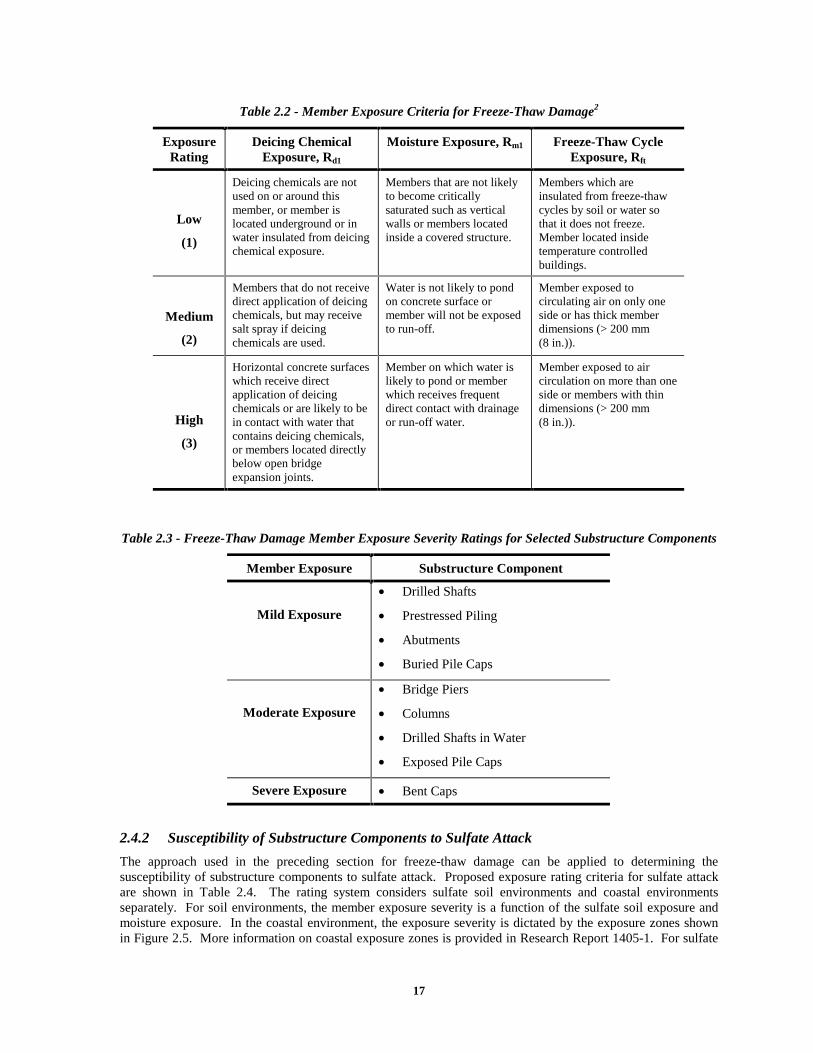
2.4.2 Susceptibility of Substructure Components to Sulfate Attack
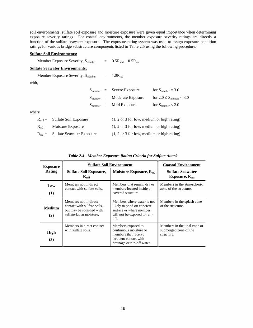
The approach used in the preceding section for freeze-thaw damage can be applied to determining the susceptibility of substructure components to sulfate attack. Proposed exposure rating criteria for sulfate attack are shown in Table 2.4. The rating system considers sulfate soil environments and coastal environments separately. For soil environments, the member exposure severity is a function of the sulfate soil exposure and moisture exposure. In the coastal environment, the exposure severity is dictated by the exposure zones shown in Figure 2.5. More information on coastal exposure zones is provided in Research Report 1405-1. For sulfate
18
soil environments, sulfate soil exposure and moisture exposure were given equal importance when determining exposure severity ratings. For coastal environments, the member exposure severity ratings are directly a function of the sulfate seawater exposure. The exposure rating system was used to assign exposure condition ratings for various bridge substructure components listed in Table 2.5 using the following procedure.
Sulfate Soil Environments:
Member Exposure Severity, Smember = 0.5Rsoil + 0.5Rm2
Sulfate Seawater Environments:
Member Exposure Severity, Smember = 1.0Rsea
with,
Smember = Severe Exposure for Smember = 3.0
Smember = Moderate Exposure for 2.0 ≤ Smember < 3.0
Smember = Mild Exposure for Smember < 2.0
where
Rsoil = Sulfate Soil Exposure (1, 2 or 3 for low, medium or high rating)
Rm2 = Moisture Exposure (1, 2 or 3 for low, medium or high rating)
Rsea = Sulfate Seawater Exposure (1, 2 or 3 for low, medium or high rating)
Table 2.4 - Member Exposure Rating Criteria for Sulfate Attack
Sulfate Soil Environment Coastal Environment Exposure Rating Sulfate Soil Exposure,
Rsoil
Moisture Exposure, Rm2 Sulfate Seawater Exposure, Rsea
Low
(1)
Members not in direct contact with sulfate soils.
Members that remain dry or members located inside a covered structure.
Members in the atmospheric zone of the structure.
Medium
(2)
Members not in direct contact with sulfate soils, but may be splashed with sulfate-laden moisture.
Members where water is not likely to pond on concrete surface or where member will not be exposed to run-off.
Members in the splash zone of the structure.
High
(3)
Members in direct contact with sulfate soils.
Members exposed to continuous moisture or members that receive frequent contact with drainage or run-off water.
Members in the tidal zone or submerged zone of the structure.

19
AtmosphericZone
SplashZone
TidalZone
SubmergedZone
high tide
low tide
corrosion ofreinforcement
freezing andthawing damage
sulfate attack
alkali-aggregatereaction
Figure 2.5 - Substructure Exposure Zones and Forms of Deterioration in Coastal Seawater Exposures
Table 2.5 - Sulfate Attack Member Exposure Severity Ratings for Selected Substructure Components
Substructure Component Member Exposure Sulfate Soil Environment Coastal Environment
Mild Exposure
• Bent Caps
• Bridge Piers (no soil at base)
• Columns (no soil at base)
• Bent Caps (atmospheric zone)
• Bridge Piers (atmospheric zone)
• Columns (atmospheric zone)
Moderate Exposure
• Abutments
• Bridge Piers (soil at base)
• Columns (soil at base)
• Bent Caps (splash zone)
• Bridge Piers (splash zone)
• Columns (splash zone)
Severe Exposure
• Drilled Shafts
• Prestressed Piling
• Pile Caps
• Bridge Piers (tidal and submerged zone)
• Columns (tidal and submerged zone)
• Drilled Shafts
• Prestressed Piling
• Pile Caps
2.4.3 Susceptibility of Substructure Components to Reinforcement Corrosion
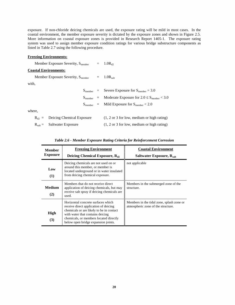
Proposed exposure rating criteria for the susceptibility of substructure components to corrosion is shown in Table 2.6. The rating system considers freezing environments and coastal environments separately. For freezing environments, the member exposure severity is a function of the chloride-based deicing chemical
20
exposure. If non-chloride deicing chemicals are used, the exposure rating will be mild in most cases. In the coastal environment, the member exposure severity is dictated by the exposure zones and shown in Figure 2.5. More information on coastal exposure zones is provided in Research Report 1405-1. The exposure rating system was used to assign member exposure condition ratings for various bridge substructure components as listed in Table 2.7 using the following procedure.
Freezing Environments:
Member Exposure Severity, Smember = 1.0Rd2
Coastal Environments:
Member Exposure Severity, Smember = 1.0Rsalt
with,
Smember = Severe Exposure for Smember = 3.0
Smember = Moderate Exposure for 2.0 ≤ Smember < 3.0
Smember = Mild Exposure for Smember < 2.0
where,
Rd2 = Deicing Chemical Exposure (1, 2 or 3 for low, medium or high rating)
Rsalt = Saltwater Exposure (1, 2 or 3 for low, medium or high rating)
Table 2.6 - Member Exposure Rating Criteria for Reinforcement Corrosion
Freezing Environment Coastal Environment Member Exposure Deicing Chemical Exposure, Rd2 Saltwater Exposure, Rsalt
Low
(1)
Deicing chemicals are not used on or around this member, or member is located underground or in water insulated from deicing chemical exposure.
not applicable
Medium
(2)
Members that do not receive direct application of deicing chemicals, but may receive salt spray if deicing chemicals are used.
Members in the submerged zone of the structure.
High
(3)
Horizontal concrete surfaces which receive direct application of deicing chemicals or are likely to be in contact with water that contains deicing chemicals, or members located directly below open bridge expansion joints.
Members in the tidal zone, splash zone or atmospheric zone of the structure.
21
Table 2.7 - Reinforcement Corrosion Member Exposure Severity Ratings for Selected Substructure Components
Substructure Component Member Exposure Freezing Environment Coastal Environment
Mild Exposure
• Drilled Shafts
• Prestressed Piling
• Pile Caps (buried)
• not applicable
Moderate Exposure
• Columns Adjacent to Roadways
• Bridge Piers Adjacent to Roadways
• Drilled Shafts in Water
• Prestressed Piling
• Pile Caps (submerged)
Severe Exposure
• Bent Caps at Expansion Joints
• Bridge Piers at Expansion Joints
• Columns at Expansion Joints
• Abutments at Expansion Joints
• Bent Caps
• Abutments
• Bridge Piers
• Columns
• Pile Caps (not submerged)
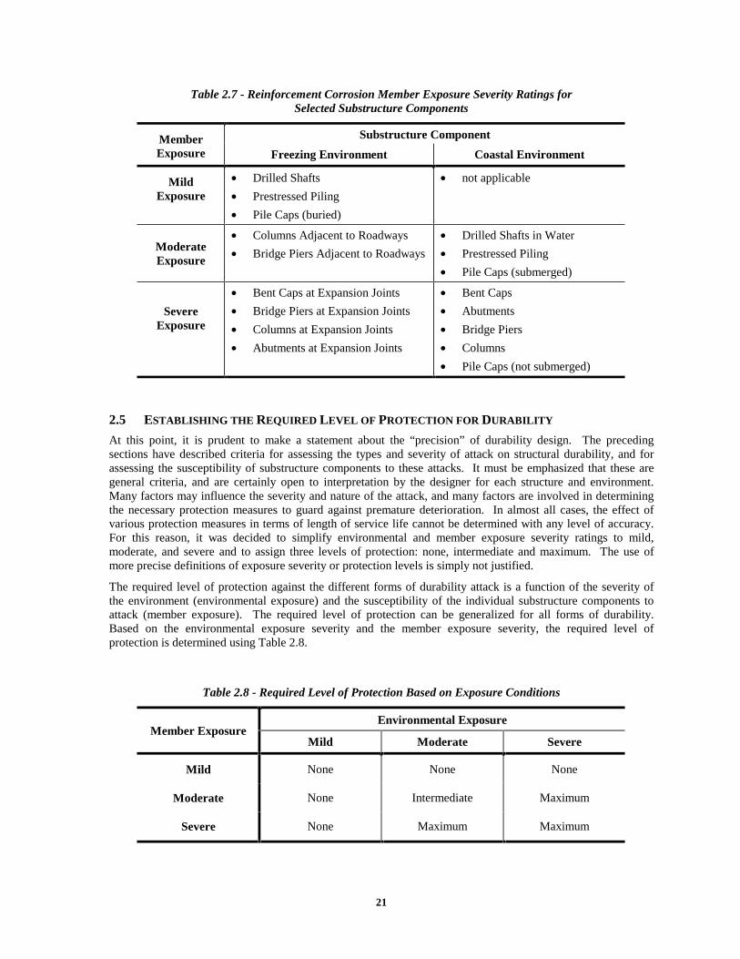
2.5 ESTABLISHING THE REQUIRED LEVEL OF PROTECTION FOR DURABILITY
At this point, it is prudent to make a statement about the “precision” of durability design. The preceding sections have described criteria for assessing the types and severity of attack on structural durability, and for assessing the susceptibility of substructure components to these attacks. It must be emphasized that these are general criteria, and are certainly open to interpretation by the designer for each structure and environment. Many factors may influence the severity and nature of the attack, and many factors are involved in determining the necessary protection measures to guard against premature deterioration. In almost all cases, the effect of various protection measures in terms of length of service life cannot be determined with any level of accuracy. For this reason, it was decided to simplify environmental and member exposure severity ratings to mild, moderate, and severe and to assign three levels of protection: none, intermediate and maximum. The use of more precise definitions of exposure severity or protection levels is simply not justified.
The required level of protection against the different forms of durability attack is a function of the severity of the environment (environmental exposure) and the susceptibility of the individual substructure components to attack (member exposure). The required level of protection can be generalized for all forms of durability. Based on the environmental exposure severity and the member exposure severity, the required level of protection is determined using Table 2.8.
Table 2.8 - Required Level of Protection Based on Exposure Conditions
Environmental Exposure Member Exposure
Mild Moderate Severe
Mild None None None
Moderate None Intermediate Maximum
Severe None Maximum Maximum
22
2.6 PROTECTION MEASURES FOR DURABLE STRUCTURES
Once the required level of protection has been determined, the appropriate protection measures should be selected. Due to the many uncertainties involved in determining service life and the effect of different protection measures on service life, it is not appropriate to prescribe specific measures to achieve a decisive level of protection or service life. The purpose of this section is to present options for protection measures against the various forms of environmental attack. Increasing protection is provided primarily by adding measures to create a multilevel protection scheme. Protection measures for intermediate and maximum protection against freeze-thaw damage, sulfate attack, and corrosion are presented in the following sections. These measures have been obtained from the literature review described in Research Report 1405-1. Protection measures for corrosion in post-tensioned substructures have been supplemented with the preliminary results of the testing programs from Project 0-1405.
2.6.1 Protection Measures for Freeze-Thaw Damage
2.6.1.1 General Requirements for Freeze-Thaw Environments
• Structural Form: Attention should be given to structural form and layout to minimize contact with deicing chemical run-off and splashing.
• Water-Cement Ratio: The maximum water-cement ratio shall be limited to 0.45 for thin members and members exposed to deicing chemicals, either directly or in the form of run-off. This requirement may be relaxed to 0.50 for all other situations.
• Coarse Aggregate: Coarse aggregate should be frost resistant. Standard test methods including ASTM C666,4 C6715 and C6826 may be used to evaluate the suitability of aggregates.
• Surface Treatment: Concrete surface treatments may be employed to limit moisture penetration.
2.6.1.2 Specific Requirements for Intermediate and Maximum Protection Levels
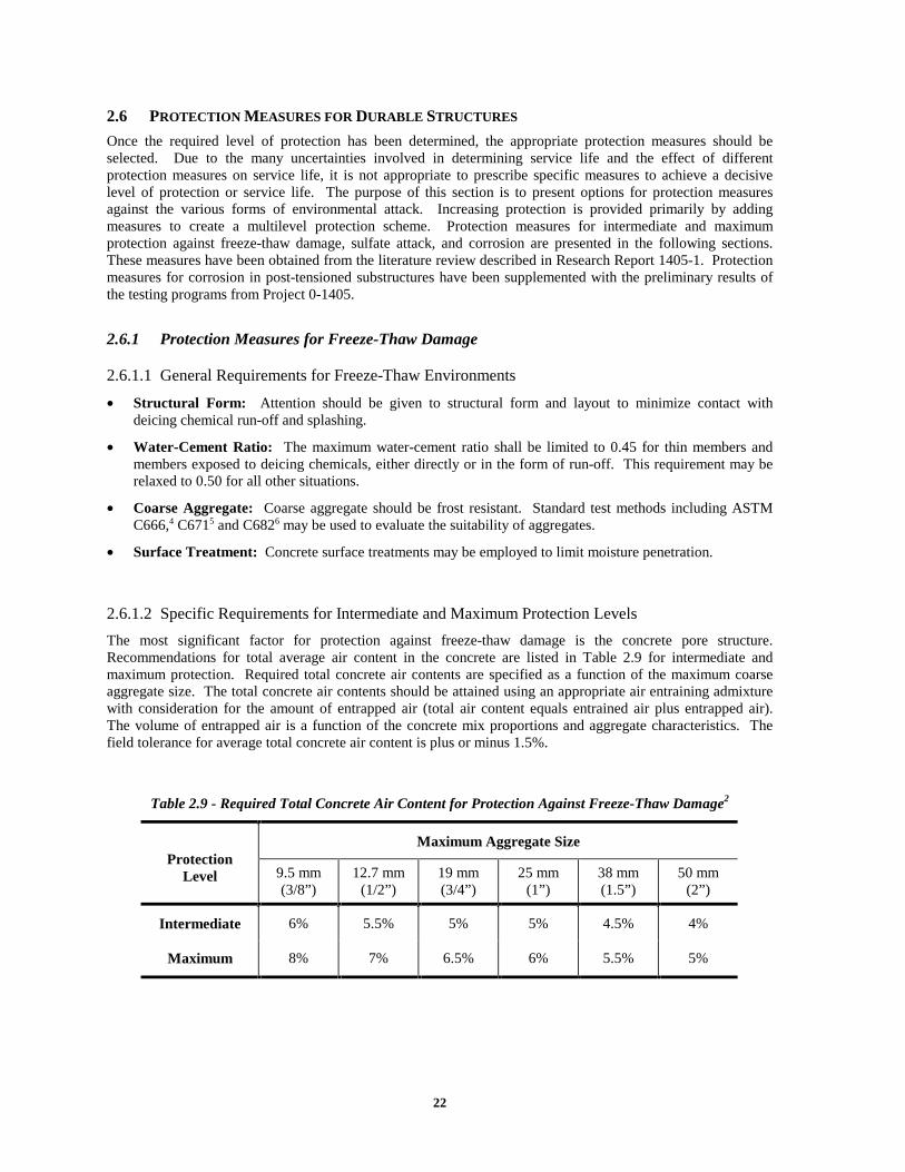
The most significant factor for protection against freeze-thaw damage is the concrete pore structure. Recommendations for total average air content in the concrete are listed in Table 2.9 for intermediate and maximum protection. Required total concrete air contents are specified as a function of the maximum coarse aggregate size. The total concrete air contents should be attained using an appropriate air entraining admixture with consideration for the amount of entrapped air (total air content equals entrained air plus entrapped air). The volume of entrapped air is a function of the concrete mix proportions and aggregate characteristics. The field tolerance for average total concrete air content is plus or minus 1.5%.
Table 2.9 - Required Total Concrete Air Content for Protection Against Freeze-Thaw Damage2
Maximum Aggregate Size Protection
Level 9.5 mm (3/8”)
12.7 mm (1/2”)
19 mm (3/4”)
25 mm (1”)
38 mm (1.5”)
50 mm (2”)
Intermediate 6% 5.5% 5% 5% 4.5% 4%
Maximum 8% 7% 6.5% 6% 5.5% 5%
23
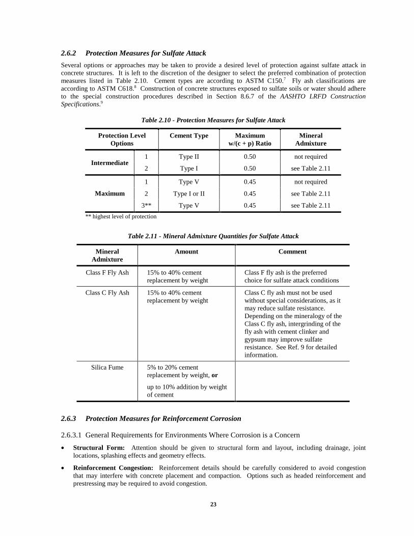
2.6.2 Protection Measures for Sulfate Attack
Several options or approaches may be taken to provide a desired level of protection against sulfate attack in concrete structures. It is left to the discretion of the designer to select the preferred combination of protection measures listed in Table 2.10. Cement types are according to ASTM C150.7 Fly ash classifications are according to ASTM C618.8 Construction of concrete structures exposed to sulfate soils or water should adhere to the special construction procedures described in Section 8.6.7 of the AASHTO LRFD Construction Specifications.9
Table 2.10 - Protection Measures for Sulfate Attack
Protection Level Options
Cement Type Maximum w/(c + p) Ratio
Mineral Admixture
1 Type II 0.50 not required Intermediate
2 Type I 0.50 see Table 2.11
1 Type V 0.45 not required
2 Type I or II 0.45 see Table 2.11 Maximum
3** Type V 0.45 see Table 2.11
** highest level of protection
Table 2.11 - Mineral Admixture Quantities for Sulfate Attack
Mineral Admixture
Amount Comment
Class F Fly Ash 15% to 40% cement replacement by weight
Class F fly ash is the preferred choice for sulfate attack conditions
Class C Fly Ash 15% to 40% cement replacement by weight
Class C fly ash must not be used without special considerations, as it may reduce sulfate resistance. Depending on the mineralogy of the Class C fly ash, intergrinding of the fly ash with cement clinker and gypsum may improve sulfate resistance. See Ref. 9 for detailed information.
Silica Fume 5% to 20% cement replacement by weight, or
up to 10% addition by weight of cement
2.6.3 Protection Measures for Reinforcement Corrosion
2.6.3.1 General Requirements for Environments Where Corrosion is a Concern
• Structural Form: Attention should be given to structural form and layout, including drainage, joint locations, splashing effects and geometry effects.
• Reinforcement Congestion: Reinforcement details should be carefully considered to avoid congestion that may interfere with concrete placement and compaction. Options such as headed reinforcement and prestressing may be required to avoid congestion.
24
• Crack Control: Cracking should be minimized. Unintended cracking due to plastic shrinkage and settlement, drying shrinkage, thermal effects and differential settlement should be controlled through detailing and proper curing conditions. Intended cracking due to structural loading should be minimized through reinforcement detailing. The use of prestressing to control cracking may be an option.
Preliminary test results from the experimental programs in this research project suggest that limiting the number of cracks and increasing crack spacing using prestressing may improve corrosion protection. The required amount of prestressing will vary for different structural components and loading conditions.
• Location of Post-Tensioning Anchorages: Post-tensioning anchorages should not be located where direct exposure to moisture and chlorides may occur. If anchorages must be located near expansion joints, member ends should be detailed to prevent exposure to chloride-laden moisture (see Research Report 1405-1).
• Segmental Joints: All precast segmental construction must use match-cast epoxy joints. The use of gaskets around duct openings on joint faces is discouraged. The preferred option is to swab the ducts immediately after segment placement and initial stressing to prevent epoxy from blocking the duct.
• Surface Treatment: Concrete surface treatments may be employed to limit moisture penetration.
• Concrete Cover: AASHTO LRFD10 concrete cover requirements of Clause 5.12.3 should be used.
• Minimum Cement Content of Concrete: Minimum cement contents should be dictated by TxDOT Specifications11 or AASHTO LRFD Specification10 Table C5.4.2.1-1 or AASHTO LRFD Construction Specification9 Clause 8.2.
• Reinforcing Bar Supports: Non-metallic (plastic) bar chairs and bolster strips should be used at all locations where supports bear against forms for exposed concrete surfaces.
Plastic tipped bar chairs and bolster strips corroded in beam and column test specimens, producing concrete spalling and extensive rust staining.
• Construction Procedures: Construction of concrete structures exposed to saltwater should adhere to the special procedures described in Clause 8.6.6 of the AASHTO LRFD Construction Specifications.9

25
2.6.3.2 Specific Measures for Intermediate Corrosion Protection
Table 2.12 - Intermediate Corrosion Protection Measures
Design Component
Protection Requirements
Comments
Concrete:
w/c ratio 0.45 maximum
mineral admixtures
optional Mineral admixtures such as fly ash and silica fume may be required to meet permeability requirements. Required mineral admixture quantities can be determined based on permeability, workability and strength requirements.
permeability medium to low Rapid chloride ion permeability according to AASHTO T27712 or ASTM C1202.13
Concrete permeability requirements are similar to those proposed for performance based specifications for concrete.14 Reduced permeability may be achieved using low water-cement ratios and mineral admixtures.
Mild Steel Reinforcement
epoxy-coated reinforcement
Coating quality is extremely important to the effectiveness of epoxy-coated reinforcement, as indicated by recent research15,16 and the poor durability performance of some structures with epoxy-coated bars.
Prestressing Strand bare strands (uncoated) Increased protection options may not be warranted at the intermediate protection level.
Post-Tensioning Duct
plastic ducts should be used
vacuum testing or pressure testing for leaks should be performed prior to grouting
Plastic ducts should be used with watertight couplers for duct splices and connection to anchorage hardware. Plastic duct systems may be tested for air leaks prior to grouting. Leaks should be identified and sealed to ensure a waterproof protection barrier for the tendon.
Post-Tensioning Grout
w/c ≤ 0.44 Standard grout11 should be adequate for intermediate protection levels, provided that proper grouting procedures are used. The use of expanding admixtures and corrosion inhibitors should be discouraged based on experimental results.17,18 If large vertical distances are encountered in the tendon profile, the use of Post-Tensioning Grout Option 2 in Table 2.13 should be considered.
26
Table 2.12 - Intermediate Corrosion Protection Measures - Continued
Design Component
Protection Requirements
Comments
Anchorage Protection
anchorages should be located in recessed pockets
pockets should be filled with non-shrink concrete or mortar
pocket surfaces and exposed anchorage components should be coated with an epoxy bonding agent prior to filling
Requirements are based on TxDOT Specifications19 and practice, and past research.
Post-Tensioning System
standard post-tensioning systems
Increased protection options may not be warranted at the intermediate protection level.
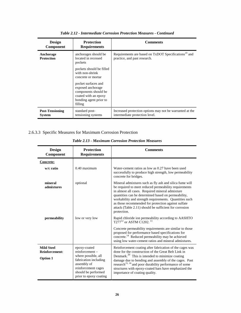
2.6.3.3 Specific Measures for Maximum Corrosion Protection
Table 2.13 - Maximum Corrosion Protection Measures
Design Component
Protection Requirements
Comments
Concrete:
w/c ratio 0.40 maximum Water-cement ratios as low as 0.27 have been used successfully to produce high strength, low permeability concrete for bridges.
mineral admixtures
optional Mineral admixtures such as fly ash and silica fume will be required to meet reduced permeability requirements in almost all cases. Required mineral admixture quantities can be determined based on permeability, workability and strength requirements. Quantities such as those recommended for protection against sulfate attack (Table 2.11) should be sufficient for corrosion protection.
permeability low or very low Rapid chloride ion permeability according to AASHTO T27712 or ASTM C1202. 13
Concrete permeability requirements are similar to those proposed for performance based specifications for concrete.14 Reduced permeability may be achieved using low water-cement ratios and mineral admixtures.
Mild Steel Reinforcement:
Option 1
epoxy-coated reinforcement – where possible, all fabrication including assembly of reinforcement cages should be performed prior to epoxy coating
Reinforcement coating after fabrication of the cages was done for the construction of the Great Belt Link in Denmark.20 This is intended to minimize coating damage due to bending and assembly of the cages. Past research15, 16 and poor durability performance of some structures with epoxy-coated bars have emphasized the importance of coating quality.
27
Table 2.13 - Maximum Corrosion Protection Measures - Continued
Design Component
Protection Requirements
Comments
Mild Steel Reinforcement:
Option 2
stainless steel reinforcement
Research has shown excellent corrosion resistance of stainless steel reinforcement in concrete in comparison to galvanized and epoxy-coated reinforcement.21,22,23 Evaluation of cost data has shown increases of 6% to 16% in overall project costs when stainless steel reinforcement is specified 22 When life cycle costs are considered, stainless steel may be more cost effective than its alternatives.
Prestressing Strand epoxy-coated and filled strands
Research18,24 has demonstrated excellent performance of epoxy-coated strand in comparison to bare strand.
Post-Tensioning Duct
plastic ducts should be used
vacuum testing or pressure testing for leaks should be performed prior to grouting
Plastic ducts should be used with watertight couplers for duct splices and connection to anchorage hardware. Plastic duct systems may be tested for air leaks prior to grouting. Leaks should be identified and sealed to ensure a waterproof protection barrier for the tendon.
Post-Tensioning Grout:
Option 1
w/(c + p) = 0.35
30% Fly ash by weight
superplasticizer as needed for fluidity
Grout based on research by Schokker.25 This grout offers excellent corrosion protection. Superplasticizer dosage should be determined using a flow cone test for fluidity (ASTM C93926).
Post-Tensioning Grout:
Option 2
w/c = 0.32
antibleed admixture
superplasticizer as needed for fluidity
Grout based on research by Schokker.25 This grout offers good corrosion protection and high resistance to bleed, and should be used in situations where large variations in height occur along the tendon profile. Superplasticizer dosage should be determined using a flow cone test for fluidity.26 Antibleed admixture dosage should be based on the Gelman Pressure Test (see Refs. 18 and 25).
Anchorage Protection
anchorages should be located in recessed pockets
pockets should be filled with non-shrink concrete or mortar
pocket surfaces and exposed anchorage components should be coated with an epoxy bonding agent prior to filling
Requirements are based on TxDOT Specifications19 and practice, and past research.

28
Table 2.13 - Maximum Corrosion Protection Measures – Continued
Design Component
Protection Requirements
Comments
Post-Tensioning System
specialized encapsulated post-tensioning systems for aggressive environments should be used.
(e.g., VSL CS-Super Post-Tensioning System)
Encapsulated and electrically isolated post-tensioning systems meet many of the suggestions of the U.K. Concrete Society Report on Durable Bonded Post-tensioned Concrete Bridges.27
The cost of the VSL CS-Super Post-tensioning System is approximately 10% to 12% higher than standard VSL multistrand tendon anchorage systems.28 The anchorages are less expensive due to the use of the composite bearing plate (less steel), but the PT-Plus plastic duct is more expensive than galvanized steel duct.28 When overall project costs are considered, a project cost increase of much less than 10% would be expected.
2.7 DURABILITY DESIGN PROCEDURE
The preceding sections have presented a generalized procedure for bridge substructure durability design. The steps of the durability design process are summarized below.
1. Determine the location and general configuration of the bridge under consideration.
2. Use Figure 2.2 to determine what forms of attack on durability may be expected for the given location and environment.
3. Assess the severity of the environmental exposure using Figure 2.3 for freeze-thaw damage, Table 2.1 for sulfate attack and Figure 2.4 for corrosion in deicing chemical exposures. For corrosion in coastal exposures, the environmental exposure may be taken as severe.
4. Assess the severity of the member exposure for each substructure component using Table 2.2 for freeze-thaw environments, Table 2.4 for sulfate attack environments, and Table 2.6 for reinforcement corrosion environments.
5. Determine the required level of protection for each substructure component and form of attack using Table 2.8.
6. Select the necessary protection measures from those presented in Section 2.6.
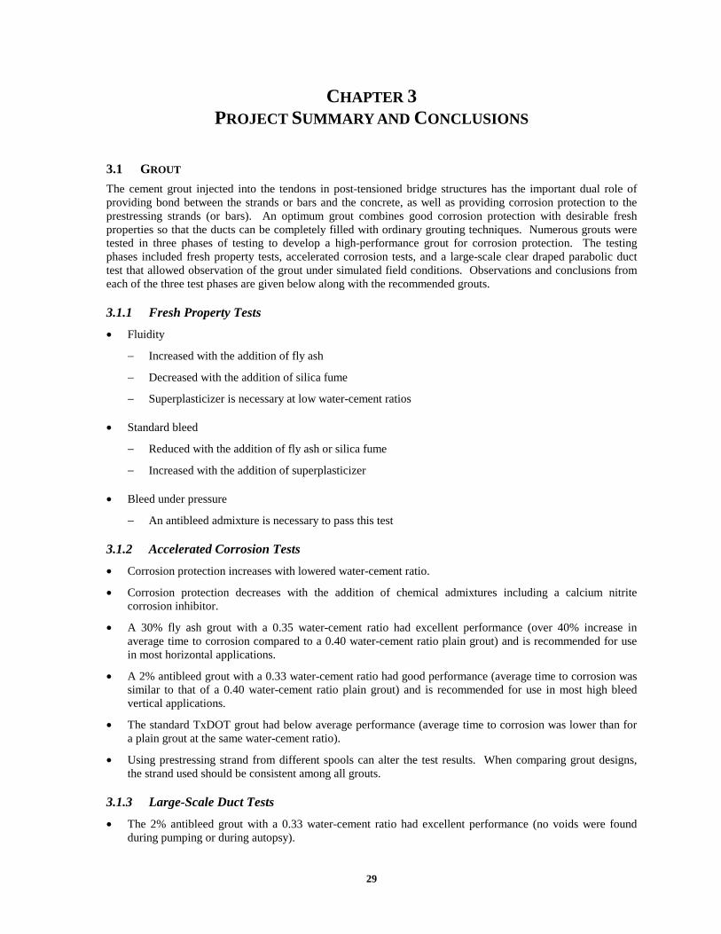
29
CHAPTER 3 PROJECT SUMMARY AND CONCLUSIONS
3.1 GROUT
The cement grout injected into the tendons in post-tensioned bridge structures has the important dual role of providing bond between the strands or bars and the concrete, as well as providing corrosion protection to the prestressing strands (or bars). An optimum grout combines good corrosion protection with desirable fresh properties so that the ducts can be completely filled with ordinary grouting techniques. Numerous grouts were tested in three phases of testing to develop a high-performance grout for corrosion protection. The testing phases included fresh property tests, accelerated corrosion tests, and a large-scale clear draped parabolic duct test that allowed observation of the grout under simulated field conditions. Observations and conclusions from each of the three test phases are given below along with the recommended grouts.
3.1.1 Fresh Property Tests
• Fluidity
− Increased with the addition of fly ash
− Decreased with the addition of silica fume
− Superplasticizer is necessary at low water-cement ratios
• Standard bleed
− Reduced with the addition of fly ash or silica fume
− Increased with the addition of superplasticizer
• Bleed under pressure
− An antibleed admixture is necessary to pass this test
3.1.2 Accelerated Corrosion Tests
• Corrosion protection increases with lowered water-cement ratio.
• Corrosion protection decreases with the addition of chemical admixtures including a calcium nitrite corrosion inhibitor.
• A 30% fly ash grout with a 0.35 water-cement ratio had excellent performance (over 40% increase in average time to corrosion compared to a 0.40 water-cement ratio plain grout) and is recommended for use in most horizontal applications.
• A 2% antibleed grout with a 0.33 water-cement ratio had good performance (average time to corrosion was similar to that of a 0.40 water-cement ratio plain grout) and is recommended for use in most high bleed vertical applications.
• The standard TxDOT grout had below average performance (average time to corrosion was lower than for a plain grout at the same water-cement ratio).
• Using prestressing strand from different spools can alter the test results. When comparing grout designs, the strand used should be consistent among all grouts.
3.1.3 Large-Scale Duct Tests
• The 2% antibleed grout with a 0.33 water-cement ratio had excellent performance (no voids were found during pumping or during autopsy).

30
• The 30% fly ash grout with a 0.35 water-cement ratio had good performance (a thin void was noticed immediately after pumping, but the bleed water reabsorbed and no voids were found during autopsy).
• The TxDOT standard grout had poor performance (voids were observed forming during pumping and autopsy revealed a large void at the intermediate crest that exposed the prestressing strand).
3.2 BEAMS AND COLUMNS
3.2.1 Large-Scale Beam Specimens
Twenty-seven large-scale beam specimens were used to evaluate the effect of post-tensioning on durability, and to evaluate the relative performance of a large number of corrosion protection variables. Beams were fabricated in two phases in order to begin exposure testing on a portion of the specimens while the remaining specimens were being fabricated. Phase I included 16 beams that investigated the effect of prestress level and crack width and also included one of the high-performance grout specimens. Phase II included 11 beams that investigated duct splices, grout type, concrete type, strand type, duct type, and end anchorage protection. The Phase I beams began exposure testing in December of 1997 and the Phase II beams began exposure testing in December of 1998. Findings for the beam specimens will be more conclusive after the final autopsy of all specimens, but preliminary conclusions can be drawn from the half-cell potential readings, chloride samples, and limited autopsies.
3.2.1.1 Half-Cell Potential Measurements
Half-cell potential measurements are taken at one month intervals over a grid extending beyond the exposure testing area on the top surface of the beam. Data are analyzed as a contour plot of measurements over the beam surface to compare specimens at any given instance, and average values are used to compare specimens over time. Conclusions to date are as follows:
• As the level of post-tensioning increases, durability is increased.
• Cracking is the major source of chloride ingress observed to date.
• At this time there is no significant difference in corrosion protection between the 100% U PS and 100% S PS sections. This indicates that the 100% U PS section may have a better benefit to cost ratio. The advantage of the uncracked specimen (100% S PS) may become more apparent as the exposure testing continues.
• Corrosion activity extends outside of the ponded region.
• Partial cement replacement with fly ash improves durability due to lowered concrete permeability.
• The high-performance concrete tested improves durability by reduced cracks and lowered permeability.
• Benefits from the plastic duct, strand coatings, and encapsulated system are not likely to be fully known until final autopsy due to the difficulty in monitoring these types of materials with half-cell potentials.
3.2.1.2 Chloride Samples
Chloride samples on the ponding blocks for the Phase I beam specimens were taken after 7 months and 14 months of exposure testing. Samples were also taken from selected specimens during limited autopsy. Conclusions to date are as follows:
• Uncracked and unponded control blocks have negligible chlorides at all depths.
• Uncracked ponded blocks show penetration of chlorides, but chlorides are negligible at bar level for uncracked concrete.
• Samples taken from limited autopsy specimens indicate significantly higher chlorides at locations with cracks.
• Chloride penetration is reduced in the post-tensioned specimens.

31
3.2.1.3 Corrosion Rate Measurements Using Polarization Resistance
Corrosion rate measurements were obtained using the three-electrode procedure to measure polarization resistance. Two different devices were used: 3LP and PR Monitor. The PR Monitor uses a guard electrode for signal confinement and compensates for concrete resistance. Corrosion rate measurements were taken after seven, twelve and fifteen months of exposure. Conclusions to date are as follows:
• Corrosion rates obtained using the 3LP device were extremely high and did not correlate with specimen condition and half-cell potentials. The PR Monitor indicated lower corrosion activity than the 3LP, although moderate to high corrosion rates were indicated for most beams.
• The corrosion activity indicated by both devices, and in particular the 3LP, contradicted the half-cell potential measurements for some specimens. In general, the highest corrosion rates were obtained for the 100%U PS beams, while the most negative half-cell potentials were measured for the Non-PS beams. Numerous possible factors were investigated, but no firm conclusions could be made other than several limitations exist for the 3LP device and the polarization resistance technique in general.
• The corrosion rate measurements indicated localized areas of high corrosion activity may be present in some beams. This occurrence was confirmed in the 100%U PS beams during the limited autopsy by invasive inspection, where severe corrosion was found on stirrups coinciding with flexural cracks.
• The PR Monitor appears to provide a better assessment of corrosion rate than the 3LP device. Because of differences between the devices, it is not recommended to directly compare corrosion rates obtained using the 3LP and PR Monitor.
• The 3LP device suffers from an unconfined polarizing signal. As a result, the polarized area of steel will unknowingly be larger than expected in most cases, resulting in an overestimation of corrosion rate.
• The three electrode technique for measuring polarization resistance appears to be most useful for relative comparisons of corrosion activity rather than a quantitative assessment of corrosion rate. Relative comparisons should only be made for similar beams and similar conditions, and therefore the comparison of corrosion rates for the different levels of prestress investigated is questionable.
• Corrosion rate measurements in post-tensioned concrete structures should be approached with caution and should not be relied on as a sole method to evaluate corrosion activity.
• Regular corrosion rate measurements over time are needed to assess the amount of corrosion related distress in structural concrete. Discrete measurements may occur at instances where corrosion rates are higher or lower than normal, and give a false indication of the specimen or structural element condition.
• The PR Monitor is recommended for future corrosion rate measurements in this testing program. The 3LP device could be used as a second choice.
3.2.1.4 Crack Width Prediction for Structural Concrete with Mixed Reinforcement
• Comparison of measured crack data with several crack prediction models produced widely varying results. This finding suggests that not all crack prediction methods are appropriate for structural concrete members with a combination of mild steel and prestressed reinforcement.
• The Gergely-Lutz crack width model provided an excellent prediction of maximum crack widths for the Non-PS and 2/3 PS beams, and a conservative estimate for the 100%U PS beams. The Gergely-Lutz model was applied using the recommendations of Armstrong et al. This model is relatively easy to apply, and is recommended for sections with mixed reinforcement.
• The Batchelor and El Shahawi crack width expression provided a very good prediction of maximum crack widths for the 2/3 PS and 100%U PS beams. This very simple model is also recommended for sections with mixed reinforcement.

32
3.2.1.5 Limited Autopsy by Invasive Inspection
Three specimens were chosen for limited autopsy. Two of the 100% U PS specimens and one Non-PS specimen were inspected. Conclusions from the limited autopsies are as follows:
• The Non-PS specimen showed signs of corrosion at both inspected locations. The stirrup under the crack had extensive light pitting with two concentrated areas of pitting. The reinforcement away from the crack had only one area of noticeable pitting.
• The stirrup in the cracked region for the post-tensioned specimen with little staining showed no signs of corrosion. The stirrup uncovered under a crack with staining showed similar corrosion to the stirrup in the Non-PS section.
• The post-tensioning duct showed no signs of corrosion, and was fully grouted at the inspection location.
• The heavily cracked Phase I specimens are showing a large amount of staining at the cracks. In addition, many of the Phase I specimens are showing staining from the corrosion of the plastic tipped steel bolster strips. In some cases, the concrete has spalled revealing the plastic tips. This unsightly staining and spalling may be remedied by the use of fully plastic chairs. Plastic chairs were used in the Phase II specimens so that their use could be evaluated. At this point, the staining and spalling away from cracked areas observed in the Phase I specimens is not evident in the Phase II specimens.
• Visible signs of corrosion of the reinforcement were limited to the cracked locations at this stage of exposure testing. The large number of cracks and greater crack widths associated with the specimens containing lower levels of prestressing will likely cause deterioration of the these specimens first. A greater depth of concrete with a reduced number of cracks protects the post-tensioning ducts.
3.2.2 Large-Scale Column Specimens
Ten large-scale column specimens were used to examine corrosion protection mechanisms and chloride ion transport (“wicking” effect) in various column connection configurations and to evaluate column corrosion protection measures. Variables included foundation connection, post-tensioning system protection, concrete type, and loading. Column exposure testing began in July of 1996. Findings for the column specimens will be more conclusive after the final autopsy of all specimens, but preliminary conclusions drawn from the half-cell potential readings, chloride samples, and limited autopsies are given below.
3.2.2.1 Half-Cell Potential Measurements
Half-cell potential measurements were taken at one-month intervals. Readings are taken at several heights for the reinforcing bars and the post-tensioning bars. The conclusions from the readings to date are as follows:
• Corrosion activity is higher on the dripper side of the column.
• Corrosion activity is higher at levels closer to the base.
• Readings are higher for the submerged concrete and for the epoxy-coated bars, although this is not necessarily an indication of corrosion. Readings are typically high in these circumstances due to a restriction of oxygen in the corrosion cell below the water level.
3.2.2.2 Chloride Samples
Chloride samples were taken directly from the column specimens after 20 months and 32 months of exposure testing. Samples were taken at several heights from the base and on both the dripper and non-dripper sides of the columns. The conclusions from the samples taken to date are as follows:
• Data from chloride samples taken on the non-dripper side of the columns indicate that chlorides have traveled significantly above the water line (“wicking” effect).
• Chloride levels on the dripper side were significantly higher than levels on the non-dripper side.
• Columns with fly ash concrete showed the lowest levels of chloride penetration.

33
• Several specimens showed higher levels of chlorides at the middle sample level than at the submerged sample level. It is likely that the effect of wicking combined with an environment that allows drying of the concrete is resulting in more severe exposure conditions for these samples.
3.2.2.3 Limited Autopsy by Invasive Inspection
Two columns were chosen for invasive inspection: one post-tensioned column and one non post-tensioned column. No visible signs of corrosion were found on the reinforcing bar or post-tensioning duct for the post-tensioned specimen. The reinforcing bar uncovered in the non post-tensioned specimen had some light pitting corrosion. These findings were consistent with findings from the half-cell potential readings.
3.3 MACROCELLS
Several conclusions can be drawn after nearly four and a half years of extreme, accelerated exposure testing. Since the majority of corrosion activity has occurred in specimens with dry joints (eleven of twelve specimens with corrosion), these conclusions are based on a limited data set and therefore could be subject to change.
At the time of reporting, exposure testing is continuing for nineteen specimens (one of each specimen type). Continued exposure testing may provide additional results to assist comparison of variables.
3.3.1 Overall Performance
• Overall performance of the segmental macrocell corrosion specimens in this program is very good with only minor corrosion detected in a limited number of specimens.
• Metal loss calculations indicate that corrosion to date is minor or negligible.
• Possible strength degradation, in the form of pitting corrosion on prestressing strand, was found in only one specimen.
3.3.2 Assessing Corrosion Activity Using Half-Cell Potential Measurements
• The magnitude of half-cell potential measurements may not necessarily indicate the severity of corrosion activity. Very negative half-cell potentials may result from sources other than significant corrosion activity. Low half-cell potentials (more positive than guidelines for high probability of corrosion) may be measured for conditions of corrosion activity. Therefore it is important to consider the variation of half-cell potentials over time to assess corrosion activity and detect the initiation of corrosion.
3.3.3 Segmental Joints
• All long-term and significant corrosion has occurred in specimens with dry joints. Seventy-eight percent (eleven of fourteen) of the dry joint specimens displayed corrosion activity. Specimens with dry joints showed increased chloride penetration and increased corrosion of galvanized steel duct, prestressing strand and mild steel reinforcement. Test results indicate that dry joints do not provide corrosion protection for internal tendons where aggressive exposure may occur.
• The mild steel reinforcement is corroding instead of the prestressing strand in seven of the eleven dry joint specimens with corrosion activity. This occurrence is attributed to penetration of chlorides at the dry segmental joint and indicates a possible increased corrosion threat for mild steel reinforcement within the segment when dry joints are used. This could occur in bridges with external tendons, and highlights the importance of clear cover over the ends of longitudinal bars in the segments.
• One out of twenty-four specimens with epoxy joints has shown corrosion activity. This specimen was the most recent to display an onset of corrosion, and measured corrosion current was very small. Autopsy of this specimen confirmed that the mild steel reinforcement was corroding rather than the prestressing strand. Measured chloride profiles for this specimen suggested that corrosion resulted from an external source of moisture and chlorides rather than from penetration at the epoxy joint or through the concrete.
• Only very minor prestressing strand corrosion was found in specimens with epoxy joints. Corrosion of the galvanized steel duct was reduced in extent and severity in specimens with epoxy joints. The experimental

34
data to date indicates that thin epoxy joints provide substantially improved corrosion protection for internal tendons in segmental construction.
• The use of gaskets in epoxy joints may interfere with epoxy coverage on the joint. Autopsied epoxy/gasket joint specimens found incomplete epoxy coverage near the duct openings, leading to increased chloride penetration and duct corrosion. The observed deficiencies occurred in carefully controlled laboratory conditions, and could possibly be worse under field conditions.
3.3.4 Ducts for Internal Post-Tensioning
• Strand corrosion was not detected during exposure testing in any epoxy joint specimens with plastic ducts. Reversed macrocell corrosion developed in the four dry joint specimens with plastic ducts. Formation of the reversed corrosion macrocells indicates that the plastic duct is providing improved corrosion protection for the prestressing strand (tendon), even when penetration of chlorides at the dry joints has caused rebar corrosion.
• Forensic examination revealed only very minor corrosion or discoloration on the prestressing strand from specimens with plastic ducts.
• Galvanized steel ducts were corroded in all cases. Duct corrosion led to concrete cracking along the line of the tendon in many specimens. Ducts were corroded through in nearly two-thirds of the specimens, eliminating the duct as corrosion protection for the prestressing tendon. The concrete cover in the test specimens was lower than specification, contributing to the poor performance of the galvanized duct in such a short period of time. However, test results indicate the potential for durability problems when using galvanized ducts in aggressive exposures.
• Specimens with plastic ducts and epoxy joints had the best overall performance in the testing program (quantified in terms of strand, mild steel and duct corrosion).
3.3.5 Joint Precompression
• The range of joint precompression investigated did not affect the time to corrosion or corrosion severity for steel reinforcement.
• In dry joint specimens with steel ducts, corrosion of the steel duct decreased as joint prestress increased.
3.3.6 Grouts for Bonded Post-Tensioning
• The most severe corrosion of the prestressing tendon was found where calcium nitrite corrosion inhibitor was used in the grout. Test results suggest calcium nitrite should not be used in cement grouts.
• Two specimens with silica fume in the grout (and epoxy joints) did not show corrosion activity.
• Grout voids resulted in increased corrosion severity of galvanized steel ducts in some cases. This finding highlights that proper grout mix proportioning and grouting procedures are important not only for corrosion protection of the prestressing strand, but may also be required for the duct.
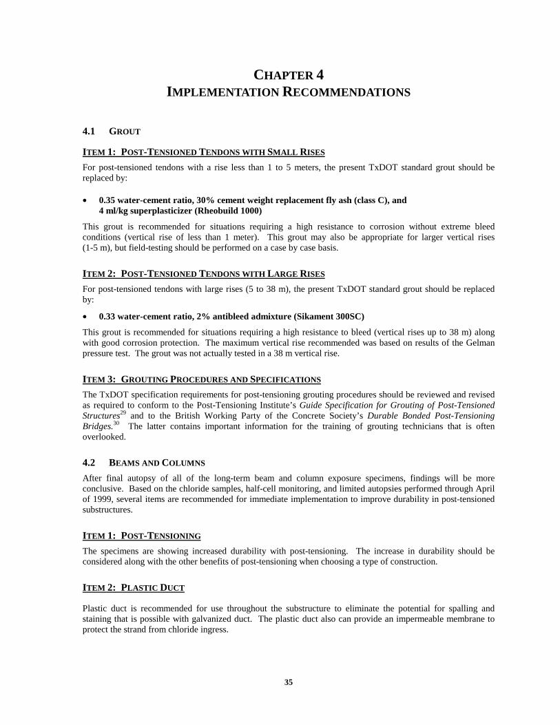
35
CHAPTER 4 IMPLEMENTATION RECOMMENDATIONS
4.1 GROUT
ITEM 1: POST-TENSIONED TENDONS WITH SMALL RISES
For post-tensioned tendons with a rise less than 1 to 5 meters, the present TxDOT standard grout should be replaced by:
• 0.35 water-cement ratio, 30% cement weight replacement fly ash (class C), and 4 ml/kg superplasticizer (Rheobuild 1000)
This grout is recommended for situations requiring a high resistance to corrosion without extreme bleed conditions (vertical rise of less than 1 meter). This grout may also be appropriate for larger vertical rises (1-5 m), but field-testing should be performed on a case by case basis.
ITEM 2: POST-TENSIONED TENDONS WITH LARGE RISES
For post-tensioned tendons with large rises (5 to 38 m), the present TxDOT standard grout should be replaced by:
• 0.33 water-cement ratio, 2% antibleed admixture (Sikament 300SC)
This grout is recommended for situations requiring a high resistance to bleed (vertical rises up to 38 m) along with good corrosion protection. The maximum vertical rise recommended was based on results of the Gelman pressure test. The grout was not actually tested in a 38 m vertical rise.
ITEM 3: GROUTING PROCEDURES AND SPECIFICATIONS
The TxDOT specification requirements for post-tensioning grouting procedures should be reviewed and revised as required to conform to the Post-Tensioning Institute’s Guide Specification for Grouting of Post-Tensioned Structures29 and to the British Working Party of the Concrete Society’s Durable Bonded Post-Tensioning Bridges.30 The latter contains important information for the training of grouting technicians that is often overlooked.
4.2 BEAMS AND COLUMNS
After final autopsy of all of the long-term beam and column exposure specimens, findings will be more conclusive. Based on the chloride samples, half-cell monitoring, and limited autopsies performed through April of 1999, several items are recommended for immediate implementation to improve durability in post-tensioned substructures.
ITEM 1: POST-TENSIONING
The specimens are showing increased durability with post-tensioning. The increase in durability should be considered along with the other benefits of post-tensioning when choosing a type of construction.
ITEM 2: PLASTIC DUCT
Plastic duct is recommended for use throughout the substructure to eliminate the potential for spalling and staining that is possible with galvanized duct. The plastic duct also can provide an impermeable membrane to protect the strand from chloride ingress.

36
ITEM 3: PLASTIC CHAIRS
Fully plastic chairs are recommended for use throughout the substructure to eliminate unsightly staining and spalling. Chairs or bolster strips that contain any steel (included plastic tipped steel chairs) should be avoided.
ITEM 4: FLY ASH CONCRETE
Fly ash concrete is recommended for all substructure elements. The significantly reduced permeability slows chloride ingress. This substitution can be accomplished with little or no additional cost.
ITEM 5: HIGH-PERFORMANCE CONCRETE
The high-performance concrete specimens are showing improved corrosion resistance due to both the lowered concrete permeability and crack control.
4.3 MACROCELLS
ITEM 1: JOINT TYPE – INTERNAL PRESTRESSING
Dry joints should not be used with internal prestressing tendons. This practice is prohibited by the AASHTO Guide Specifications for Segmental Bridges, and the very poor corrosion performance of dry joints illustrates the high potential for corrosion if Guide Specifications are ignored. Match-cast epoxy joints provide excellent corrosion protection for internal tendons in segmental construction.
ITEM 2: JOINT TYPE – EXTERNAL PRESTRESSING
There is an increased risk for corrosion of the segment mild steel reinforcement when dry joints are used as permitted in some exposure conditions with external post-tensioning. Epoxy joints should be used with external post-tensioning in all exposures where corrosion is a concern, including coastal saltwater exposures and deicing chemical exposures.
ITEM 3: GASKETS AROUND DUCT OPENINGS
The use of gaskets in epoxy joints does not appear to be beneficial from a durability standpoint. Test results illustrated the potential for incomplete epoxy coverage when gaskets were used around duct openings, leading to increased chloride penetration and corrosion damage. The preferred practice would be to eliminate the use of gaskets and to implement a requirement for thorough swabbing of tendon ducts immediately after initial segment placement and stressing.
ITEM 4: PLASTIC DUCT
Plastic ducts for post-tensioning should be used in all situations where aggressive exposure may occur and/or corrosion is a concern.
ITEM 5: CORROSION INHIBITOR IN GROUTS
The use of calcium nitrite corrosion inhibitor in grouts for post-tensioning should not be permitted until it can be shown that it is not detrimental to corrosion protection.
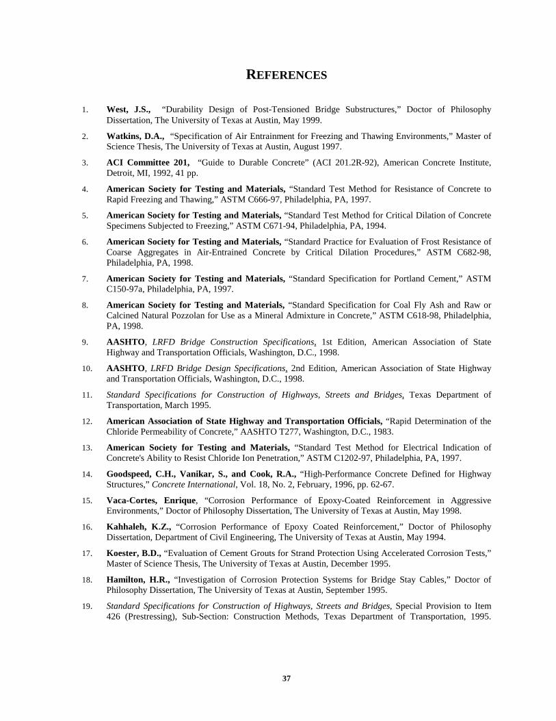
37
REFERENCES
1. West, J.S., “Durability Design of Post-Tensioned Bridge Substructures,” Doctor of Philosophy Dissertation, The University of Texas at Austin, May 1999.
2. Watkins, D.A., “Specification of Air Entrainment for Freezing and Thawing Environments,” Master of Science Thesis, The University of Texas at Austin, August 1997.
3. ACI Committee 201, “Guide to Durable Concrete” (ACI 201.2R-92), American Concrete Institute, Detroit, MI, 1992, 41 pp.
4. American Society for Testing and Materials, “Standard Test Method for Resistance of Concrete to Rapid Freezing and Thawing,” ASTM C666-97, Philadelphia, PA, 1997.
5. American Society for Testing and Materials, “Standard Test Method for Critical Dilation of Concrete Specimens Subjected to Freezing,” ASTM C671-94, Philadelphia, PA, 1994.
6. American Society for Testing and Materials, “Standard Practice for Evaluation of Frost Resistance of Coarse Aggregates in Air-Entrained Concrete by Critical Dilation Procedures,” ASTM C682-98, Philadelphia, PA, 1998.
7. American Society for Testing and Materials, “Standard Specification for Portland Cement,” ASTM C150-97a, Philadelphia, PA, 1997.
8. American Society for Testing and Materials, “Standard Specification for Coal Fly Ash and Raw or Calcined Natural Pozzolan for Use as a Mineral Admixture in Concrete,” ASTM C618-98, Philadelphia, PA, 1998.
9. AASHTO, LRFD Bridge Construction Specifications, 1st Edition, American Association of State Highway and Transportation Officials, Washington, D.C., 1998.
10. AASHTO, LRFD Bridge Design Specifications, 2nd Edition, American Association of State Highway and Transportation Officials, Washington, D.C., 1998.
11. Standard Specifications for Construction of Highways, Streets and Bridges, Texas Department of Transportation, March 1995.
12. American Association of State Highway and Transportation Officials, “Rapid Determination of the Chloride Permeability of Concrete,” AASHTO T277, Washington, D.C., 1983.
13. American Society for Testing and Materials, “Standard Test Method for Electrical Indication of Concrete's Ability to Resist Chloride Ion Penetration,” ASTM C1202-97, Philadelphia, PA, 1997.
14. Goodspeed, C.H., Vanikar, S., and Cook, R.A., “High-Performance Concrete Defined for Highway Structures,” Concrete International, Vol. 18, No. 2, February, 1996, pp. 62-67.
15. Vaca-Cortes, Enrique, “Corrosion Performance of Epoxy-Coated Reinforcement in Aggressive Environments,” Doctor of Philosophy Dissertation, The University of Texas at Austin, May 1998.
16. Kahhaleh, K.Z., “Corrosion Performance of Epoxy Coated Reinforcement,” Doctor of Philosophy Dissertation, Department of Civil Engineering, The University of Texas at Austin, May 1994.
17. Koester, B.D., “Evaluation of Cement Grouts for Strand Protection Using Accelerated Corrosion Tests,” Master of Science Thesis, The University of Texas at Austin, December 1995.
18. Hamilton, H.R., “Investigation of Corrosion Protection Systems for Bridge Stay Cables,” Doctor of Philosophy Dissertation, The University of Texas at Austin, September 1995.
19. Standard Specifications for Construction of Highways, Streets and Bridges, Special Provision to Item 426 (Prestressing), Sub-Section: Construction Methods, Texas Department of Transportation, 1995.

38
(also, personal communication with Dean Van Landuyt, Texas Department of Transportation, April 1997.)
20. Vincentsen, L.J. and Henriksen, K.R., “The Great Belt Link – Built to Last,” Concrete International, Vol. 14, No. 7, July, 1992, pp. 30-33.
21. Rasheeduzzafar, Dakhil, F.H., Bader, M.A., and Kahn, M.M., “Performance of Corrosion Resisting Steels in Chloride-Bearing Concrete,” ACI Materials Journal, Vol. 89, No. 5, September-October 1992, pp. 439-448.
22. McDonald, D.B., Sherman, M.R., Pfeifer, D.W., and Virmani, Y.P., “Stainless Steel Reinforcing as Corrosion Protection,” Concrete International, Vol. 17, No. 5, May 1995.
23. McDonald, D.B., Pfeifer, and Blake, G.T., “The Corrosion Performance of Inorganic, Ceramic and Metallic-Clad Reinforcing Bars and Solid Metallic Reinforcing Bars in Accelerated Screening Tests,” FHWA-RD-96-085, Federal Highway Administration, Mclean, Va, October 1996, 112 pp.
24. Perenchio, W.F., Fraczek, J., and Pfeifer, D.W., “Corrosion Protection of Prestressing Systems in Concrete Bridges,” NCHRP 313, Transportation Research Board, Washington, D.C., 1989, 25 pp.
25. Schokker, Andrea J., “Improving Corrosion Resistance of Post-Tensioned Substructures Emphasizing High-Performance Grouts,” Doctor of Philosophy Dissertation, The University of Texas at Austin, August 1999.
26. American Society for Testing and Materials, “Standard Test Method for Flow of Grout for Preplaced-Aggregate Concrete (Flow Cone Method),” ASTM C939-97, Philadelphia, PA, 1997.
27. Working Party of the Concrete Society, “Durable Bonded Post-Tensioned Concrete Bridges,” Technical Report No. 47, The Concrete Society, Slough, Berkshire, U.K., August 1996, 64 pp.
28. Silvestri, Giovanni, VSL Corporation, Grand Prairie, Texas, Personal Communication, June 1996.
29. Post-Tensioning Institute, “Guide Specification for Grouting of Post-Tensioned Structures,” PTI Committee on Grouting Specifications, 5th Draft, November 1997.
30. Working Party of the Concrete Society, “Durable Bonded Post-Tensioned Concrete Bridges,” Technical Report No. 47, August 1996.