Embed Size (px)
Citation preview

POST-TENSIONEDBOXGIRDERBRIDGE MANUA
301 West &born l Phoenix, Arizona 85013
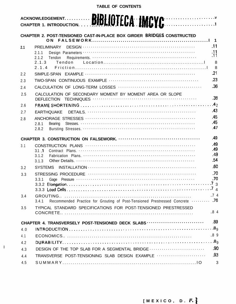
TABLE OF CONTENTS
ACKNOWLEDGEMENT. . . . . . . . . . . B~B~IOTLCA::[~~~C::::::::::::::::::::::YCHAPTER 1. INTRODUCTION. . . . . . . . . . . . . .
CHAPTER 2. POST-TENSIONED CAST-IN-PLACE BOX GIRDER BRIDG\ES CONSTRUCTEDO N F A L S E W O R K . . . . . . . . . . . . . . . . . . . . . . . . . . . . . . . . . . . . . . . . . . . . . . . . . . . . . . . . . l 1
2.1 PRELIMINARY DESIGN . . . . . . . . . . . . . . . . . . . . . . . . . . . . . . . . . . . . . . . . . . . . . . . . . . . . . . . .I1
2.1.1 Design Parameters . . . . . . . . . . . . . . . . . . . . . . . . . . . . . . . . . . . . . . . . . . . . . . . . . . . . . . . .ll2.1.2 Tendon Requirements. . . . . . . . . . . . . . . . . . . . . . . . . . . . . . . . . . . . . . . . . . . . . . . . . . . . .l 12 . 1 . 3 T e n d o n L o c a t i o n . . . . . . . . . . . . . . . . . . . . . . . . . . . . . . . . . . . . . . . . . . . . . . . . . . . . . . . . . l 82 . 1 . 4 F r i c t i o n . . . . . . . . . . . . . . . . . . . . . . . . . . . . . . . . . . . . . . . . . . . . . . . . . . . . . . . . . . . . . . . . l 8
2.2 SIMPLE-SPAN EXAMPLE . . . . . . . . . . . . . . . . . . . . . . . . . . . . . . . . . . . . . . . . . . . . . . . . . . . . . . .21
2.3 TWO-SPAN CONTINUOUS EXAMPLE . . . . . . . . . . . . . . . . . . . . . . . . . . . . . . . . . . . . . . . . . . . . .23
2.4 CALCULATION OF LONG-TERM LOSSES . . . . . . . . . . . . . . . . . . . . . . . . . . . . . . . . . . . . . . . . . .36
2.5 CALCULATION OF SECONDARY MOMENT BY MOMENT AREA OR SLOPEDEFLECTION TECHNIQUES . . . . . . . . . . . . . . . . . . . . . . . . . . . . . . . . . . . . . . . . . . . . . . . . . . . .38
2.6 FRAMESHORTENlNG.........................................................4 2
2.7 EARTHQUAKE DETAILS. . . . . . . . . . . . . . . . . . . . . . . . . . . . . . . . . . . . . . . . . . . . . . . . . . . . . . .43
2.8 ANCHORAGE STRESSES . . . . . . . . . . . . . . . . . . . . . . . . . . . . . . . . . . . . . . . . . . . . . . . . . . . . . . .45
2.8.1 Bearing Stresses. . . . . . . . . . . . . . . . . . . . . . . . . . . . . . . . . . . . . . . . . . . . . . . . . . . . . . . . . .45
2.8.2 Bursting Stresses. . . . . . . . . . . . . . . . . . . . . . . . . . . . . . . . . . . . . . . . . . . . . . . . . . . . . . . . .47
CHAPTER 3. CONSTRUCTION ON FALSEWORK. . . . . . . . . . . . . . . . . . . . . . . . . . . . . . . . . . . . . . . . . .49
3 . 1 CONSTRUCTION PLANS . . . . . . . . . . . . . . . . . . . . . . . . . . . . . . . . . . . . . . . . . . . . . . . . . . . . . . .49
3.1 .l Contract Plans. . . . . . . . . . . . . . . . . . . . . . . . . . . . . . . . . . . . . . . . . . . . . . . . . . . . . . . . . . .49
3.1.2 Fabrication Plans. . . . . . . . . . . . . . . . . . . . . . . . . . . . . . . . . . . . . . . . . . . . . . . . . . . . . . . . .49
3.1.3 Other Details. . . . . . . . . . . . . . . . . . . . . . . . . . . . . . . . . . . . . . . . . . . . . . . . . . . . . . . . . . . .54
3.2 SYSTEMS INSTALLATION . . . . . . . . . . . . . . . . . . . . . . . . . . . . . . . . . . . . . . . . . . . . . . . . . . . . . .60
3.3 STRESSING PROCEDURE . . . . . . . . . . . . . . . . . . . . . . . . . . . . . . . . . . . . . . . . . . . . . . . . . . . . . .70
3.3.1 Gage Pressure . . . . . . . . . . . . . . . . . . . . . . . . . . . . . . . . . . . . . . . . . . . . . . . . . . . . . . . . . . .703.3.2 Elongation..............................................................7 33.3.3 LoadCells..............................................................7 4
3.4 GROUTING.. . . . . . . . . . . . . . . . . . . . . . . . . . . . . . . . . . . . . . . . . . . . . . . . . . . . . . . . . . . . . . . ..7 43.4.1 Recommended Practice for Grouting of Post-Tensioned Prestressed Concrete . . . . . . . . . .76
3.5 TYPICAL STANDARD SPECIFICATIONS FOR POST-TENSIONED PRESTRESSEDCONCRETE.. . . . . . . . . . . . . . . . . . . . . . . . . . . . . . . . . . . . . . . . . . . . . . . . . . . . . . . . . . . . . . . . ..8 4
I
CHAPTER 4. TRANSVERSELY POST-TENSIONED DECK SLABS . . . . . . . . . . . . . . . . . . . . . . . . . . . . .89
4 .0 lNTRODUCTlON..............................................................8 9
4 . 1 ECONOMICS.. . . . . . . . . . . . . . . . . . . . . . . . . . . . . . . . . . . . . . . . . . . . . . . . . . . . . . . . . . . . . . ..8 9
4.2 DURABlLITY.................................................................8 9
4.3 DESIGN OF THE TOP SLAB FOR A SEGMENTAL BRIDGE . . . . . . . . . . . . . . . . . . . . . . . . . . . ,90
4.4 TRANSVERSE POST-TENSIONING SLAB DESIGN EXAMPLE . . . . . . . . . . . . . . . . . . . . . . . . .93
4.5 S U M M A R Y . . . . . . . . . . . . . . . . . . . . . . . . . . . . . . . . . . . . . . . . . . . . . . . . . . . . . . . . . . . . . . . . . . l O 3
[ M E X I C O , D .

CHAPTER 5. CAST-IN-PLACE SEGMENTAL CONSTRUCTION . . . . . . . . . . . . . . . . . . . . . . . . . . . . . .105
5 . 1 I N T R O D U C T I O N . . . . . . . . . . . . . . . . . . . . . . . . . . . . . . . . . . . . . . . . . . . . . . . . . . . . . . . . . . . . . l O 5
5.2 DESIGN AND DETAILING . . . . . . . . . . . . . . . . . . . . . . . . . . . . . . . . . . . . . . . . . . . . . . . . . . . . .1055 . 2 . 1 G e n e r a l . . . . . . . . . . . . . . . . . . . . . . . . . . . . . . . . . . . . . . . . . . . . . . . . . . . . . . . . . . . . . . . l O 55.2.2 Variable Depth Girder . . . . . . . . . . . . . . . . . . . . . . . . . . . . . . . . . . . . . . . . . . . . . . . . . . . .1055.2.3 Constant Depth Girders . . . . . . . . . . . . . . . . . . . . . . . . . . . . . . . . . . . . . . . . . . . . . . . . . . .1075.2.4 Cross-Section. . . . . . . . . . . . . . . . . . . . . . . . . . . . . . . . . . . . . . . . . . . . . . . . . . . . . . . . . . .1085 . 2 . 5 D i a p h r a g m s . . . . . . . . . . . . . . . . . . . . . . . . . . . . . . . . . . . . . . . . . . . . . . . . . . . . . . . . . . . . l O 95.2.6 Longitudinal Tendon Layout . . . . . . . . . . . . . . . . . . . . . . . . . . . . . . . . . . . . . . . . . . . . . .1095 . 2 . 7 D e t a i l s . . . . . . . . . . . . . . . . . . . . . . . . . . . . . . . . . . . . . . . . . . . . . . . . . . . . . . . . . . . . . . . . l O 9
5.3 CAST-IN-PLACE CONSTRUCTION OPTIONS . . . . . . . . . . . . . . . . . . . . . . . . . . . . . . . . . . . . . .llO5.3.1 Cantilever Supported By Falsework Bents. . . . . . . . . . . . . . . . . . . . . . . . . . . . . . . . . . . . .l 105.3.2 Traveling Truss . . . . . . . . . . . . . . . . . . . . . . . . . . . . . . . . . . . . . . . . . . . . . . . . . . . . . . . . .1125.3.3 Incremental Launching. . . . . . . . . . . . . . . . . . . . . . . . . . . . . . . . . . . . . . . . . . . . . . . . . . .1135.3.4 Form Travelers . . . . . . . . . . . . . . . . . . . . . . . . . . . . . . . . . . . . . . . . . . . . . . . . . . . . . . . . .1175.3.5 Segmental Construction On Sliding Forms . . . . . . . . . . . . . . . . . . . . . . . . . . . . . . . . . . . .118
5.4 DESIGN AND CONSTRUCTION SPECIFICATIONS FOR CAST-IN-PLACESEGMENTAL BOX GIRDER BRIDGES . . . . . . . . . . . . . . . . . . . . . . . . . . . . . . . . . . . . . . . . . . .1195.4.1 Design Specifications. . . . . . . . . . . . . . . . . . . . . . . . . . . . . . . . . . . . . . . . . . . . . . . . . . . . .1205.4.2 Construction Specifications. . . . . . . . . . . . . . . . . . . . . . . . . . . . . . . . . . . . . . . . . . . . . . . .121
AfPENDIX AND DESIGN AIDS . . . . . . . . . . . . . . . . . . . . . . . . . . . . . . . . . . . . . . . . . . . . . . . . . . . . . . .129
A.1 MOMENT COEFFICIENT FOR CONTINUOUS POST-TENSIONED STRUCTURES . . . . . . . . .129
A.2 CONCRETE MATERIALS PROPERTIES . . . . . . . . . . . . . . . . . . . . . . . . . . . . . . . . . . . . . . . . . .142
A.3 MATERIALS PROPERTIES PRESTRESSING STEEL . . . . . . . . . . . . . . . . . . . . . . . . . . . . . . . . .143
A.4 MATERIALS PROPERTIES PRESTRESSING STEEL, CONTINUED . . . . . . . . . . . . . . . . . . . . .144
A.5 MATERIALS PROPERTIES REINFORCING STEEL . . . . . . . . . . . . . . . . . . . . . . . . . . . . . . . . .145
A.6 AVAILABLE COMPUTER PROGRAMS FOR CAST-IN-PLACE SEGMENTAL DESIGN . . . . . .146
ACKNOWLEDGMENT
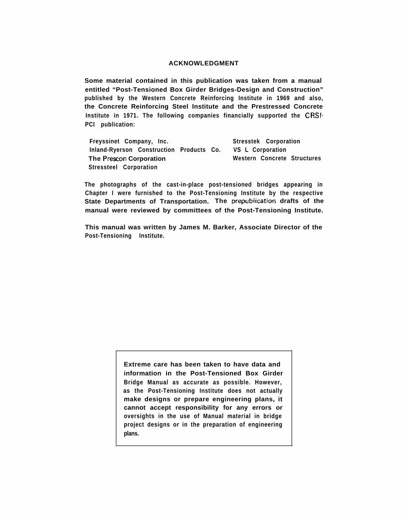
Some material contained in this publication was taken from a manualentitled “Post-Tensioned Box Girder Bridges-Design and Construction”published by the Western Concrete Reinforcing Institute in 1969 and also,the Concrete Reinforcing Steel Institute and the Prestressed ConcreteInstitute in 1971. The following companies financially supported the CRSI-PCI publication:
Freyssinet Company, Inc. Stresstek CorporationInland-Ryerson Construction Products Co. VS L CorporationThe Preston Corporation Western Concrete StructuresStressteel Corporation
The photographs of the cast-in-place post-tensioned bridges appearing inChapter I were furnished to the Post-Tensioning Institute by the respectiveState Departments of Transportation. The prepublication drafts of themanual were reviewed by committees of the Post-Tensioning Institute.
This manual was written by James M. Barker, Associate Director of thePost-Tensioning Institute.
Extreme care has been taken to have data andinformation in the Post-Tensioned Box GirderBridge Manual as accurate as possible. However,as the Post-Tensioning Institute does not actuallymake designs or prepare engineering plans, itcannot accept responsibility for any errors oroversights in the use of Manual material in bridgeproject designs or in the preparation of engineeringplans.

CHAPTER 1
INTRODUCTION
This publication presentsdesign and constructioninformation for post-tensioned concrete boxgirder bridges cast continuously on falseworkwith continuous parabolically draped tendons andcast segmentally with discontinuous tendons.Design examples of both simple-span and continu-ous-span, post-tensioned box girders cast onfalsework are presented along with a design ex-ample of a transversely post-tensioned top slab fora segmental box girder. In addition to the designexamples, information is presented on otheraspects of post-tensioning such as anchoragestresses, tendon stressing and grouting procedures.Specifications for both cast-on-falsework andsegmental construction are included to be usedas guidelines for the writing of project specifica-tions.
Post-tensioned box girder construction affordsmany advantages pertaining to economy,safety, appearance, and maintenance. The use ofa post-tensioned box girder bridge design allowslonger spans to be constructed economically. This,in turn, allows the number of columns to be re-duced and normally permitselimination of shouldercolumns. The elimination of these obstaclesgives the out-of-control driver an increased re-covery area leading to a decrease in fatalities.
In recent years, there has been an upsurge ofpublic opinion in regard to highway constructionwith many people taking the position that, al-though a highway may be necessary and beneficial,it should be built in a manner and at a locationwhich will not adversely affect their environment.One of the most important aspects of a gooddesign of a highway facility is the appearanceof the structures. It is generally accepted thatconcrete is superior in appearance and blendsmore readily with the environment than do othertypes of construction. Cast-in-place concrete, par-ticularly box girder construction, allows the use ofcurved surfaces and architectural finishes, thatenhance the appearance of the structure. Boxgirders, in addition, provide an excellent methodof concealment for unsightly utilities that detractfrom the appearance of other types of construc-tion. Use of post-tensioning in the box girdersextends the usefulness and versatility of concreteby allowing longer spans, fewer columns, andthinner sections.
Maintenance is becoming an increasingly im-portant cost factor in the selection of the type ofconstruction to be used for a bridge. Concrete
structures normally require less maintenance thansteel construction, particularly in areas whererepainting is required at frequent intervals. Theuse of post-tensioning further enhances the dura-bility of concrete construction by elimination orcontrol of cracking. By using the recommendeddesign procedure, a post-tensioned structure willremain essentially crack free under service loads.The results are a decided improvement in dura-bility, particularly for structures exposed to severeenvironments and de-icer chemicals. In addition,cast-in-place, post-tensioned structures generallyhave smoother lines, with fewer areas which havea tendency to collect dirt and debris to holdmoisture which initiates deterioration. One of themajor maintenance problem areas is the bearingassemblies on longer span structures. Removal andreplacement of these bearing assemblies generallyis very expensive and time consuming. The pierbearing assemblies can be very economicallyeliminated in cast-in-place post-tensioned con-struction by designing the structures as a frame andutilizing monolithic connections between thesuperstructure and the piers.
The following example structures demonstratethe versatility and aesthetic appeal of cast-in-place,post-tensioned box girder bridges.
The bridge shown by Fig. 1.1 is over the SouthFork of the Eel River near Garberville, California.It includes eight spans of cast-in-place, post-tensioned box girders which vary from about146 ft. to 202 ft. in length and a reinforced con-crete span measuring 84 ft. in length for a totallength of 1576 ft. The 61-ft. wide, seven-stemmed,post-tensioned box girder was cast-in-place on a2200 ft. radius curve and is superelevated to a6% slope. The vertical profile consists of constant6% grades and a 2600 ft. vertical curve whichraises the northerly end of the superstructure toapproximately 100 ft. above the river bed.
Fig. 1.2 shows the B. A. Martin Bridge over theChetco River at Brookings, Oregon. The 72 ft.wide superstructure was cast in place in unitsconsisting of 150 ft. and 97 ft. approach spansand main spans of 190 ft. - 240 ft. - 190 ft.in length. The slope-sided, parabolically haunchedbox girder is supported approximately 80 feetabove the water by single-shaft piers framedinto crossbeams. The use of post-tensioning al-
lowed longer spans for greater navigational clear-ances.
The Oregon Department of Transportation,Highway Division, made the following commentsabout the bridge:
1

.*
Fig. 1.1 - South Fork of the Eel River in California
‘Fig. 1.2 - B. A. Martin Bridge in Brookings, Oregon

“Our purpose was to construct a bridge1 ,117 feet long which would fit pleasingly intothe surrounding area, incorporate long spansto satisfy navigational clearance requirementswith low future maintenance costs.
The requirements were best fulfilled by usinga post-tensioned box girder design.
The use of standard reinforced concretewould have required shorter spans of deepergirder sections to carry the same load. Shorterspans, necessitating additional piers, would havecaused navigational problems, while the use ofdeeper girder sections would have increased thedesign problems and cost in addition to detract-ing from the appearance of the structure.
The use of steel construction for the bridgewas avoided due to the structure’s proximity tocoastal saline atmosphere, which avoided thehigh maintenance costs associated with struc-tures in similar locations. In addition, the esti-mated initial cost of a suitable steel structurewas in excess of the cost of the constructionmethod used.
The post-tensioned box girder design used hasresulted in a relatively inexpensive structurewith a clean, smooth appearance and negligible
maintenance problems in the future.” *
The 2,238 ft., First Avenue to Seventh Avenueviaduct, pictured in Fig. 1.3, carries a portion ofthe Eugene-Springfield Highway in Eugene, Oregon.The viaduct is 31 spans, 23 of which were castin place and post-tensioned. The post-tensionedspans were divided into eight post-tensionedcomponents comprised of 2, 3, and 4-span serieswith span lengths ranging from 66 ft. minimumto 166 ft. maximum. The box girder depth variesfrom 5 ft. at the center of the spans to 8 ft. at thesupports.
The length of this structure required dividingit into several series of continuous spans and clos-ing the multiple-span series with a cast-in-place,reinforced-concrete box span. Stressing was donefrom both ends of the spans and steel expansionlinks were used at the tops of the longest seriesto keep stresses at the bents, due to stressing andthermal forces, within allowable limits.
It was important that the Oregon Departmentof Transportation arrive at a design that wouldprovide ease and safety for the motorist. Atthe same time the structure was required to createa visual and practical asset to the community
Fig. 1.3 - Cast-in-place, Post-tensioned Viaduct in Eugene, Oregon

because this large viaduct provides an entrancewayto the center of a major metropolitan area. Thiswas accomplished with the long, cast-in-place,post-tensioned box girder spans incorporatingparabolic haunches and sloping beam sides. Thearea under the structure was incorporated in alinear, multi-use, 400 ft.-wide city park extendingthe entire length of the structure. The flowinglines of the design make the necessary presenceof this utilitarian traffic facility compatible withmixed light-industrial, residential surroundingsfor which the additional recreational area is wel-come.
The Canada Road Undercrossing, shown b yFig. 1.4, is a typical grade crossing used in Cali-fornia. The 7 ft.-6 in. deep, cast-in-place boxgirder is a simple span structure approximately175 ft in length and of variable width. One railline of each structure is curved to a differentradius. The nine stems of the box girder are spacedat 7 ft.-6 in. centers except for one space whichis variable to compensate for the curved side.
Figs. 1.5A thru 1.5C are post-tensioned cast-on-falsework box girder bridges located in Tennes-see. The contractors chose a different post-tension-ing system for each of the projects. Fig. 1.5A
was post-tensioned with ‘/4 inch wires. Fig. 1.5Bwas post-tensioned with thread bars and Fig. 1.5Cwith -I-wire strands.
Fig. 1.6 is a California grade crossing that hasbeen given an arch appearance with an architecturalfascia treatment utilizing white cement concrete.The bridge is a 3-span structure with spans measuringapproximately 115 ft. - 229 ft. - 214 ft. in length.The superstructure is curved and variable widthwith a ramp coming in at one end of span 2.
As can be seen from the photograph, verystriking architectural treatments can be accom-plished with cast-in-place, post-tensioned con-struction. The geometry of this bridge combinedwith the architectural treatment would havemade construction by any other method verydifficult.
The East Fork Chowchilla River Bridge, Fig. 1.7,located in Mariposa, California is a dramatic, high-level bridge providing an excellent example of thelightness and openness that can be achieved incontinuous, cast-in-place, post-tensioned concrete.Smooth flowing lines in the columns and deckprovide sculpture and aesthetics to this structurewhich blends so well with its rugged environment.
The total length of 720 ft. includes spans of 227
Fig. 1.4 - Canada Road Undercrossing in California

Fig. 1.5A - I 65/SR 76 in Robertson Co., Tennessee
Fig. 1.5B -SR 173/181 irI Sullivan Co., Tennessee
Fig. 1.5C -SR 33/SR 68 in Monroe Co., Tennessee

*
Fig. 1.6 - Route 805 Grade Separation in San Diego, CaliforniaFig. 1.6 - Route 805 Grade Separation in San Diego, California
ft., 300 ft. and 183 ft. The bridge is 150 ft. above States. The design was selected because estimatesthe valley of the Chowchilla River, making it indicated economy over competing structuralone of the highest concrete bridges in the United systems which was proven in the final costs.
Fig. 1.7 - East Fork Chowchilla River Bridge in Mariposa, California

The Pine Valley Creek Bridge, shown by Fig.1.8 was the first bridge built in this country withtraveling forms. The bridge is located about 40miles east of San Diego in the Cleveland NationalForest, a semi-arid area that is highly erodiblewhen ground cover is disturbed. The State con-sidered a steel arch, steel truss, and orthotropicsteel box girder along with the concrete boxgirder. The concrete box girder was about 10%less expensive than the others. Also, the environ-mental considerations and soil characteristicswere prime factors influencing the decision tobuild a segmental bridge erected by balancedcantilever construction.
The 450 ft. main span is flanked by spans of 380ft. and 340 ft. in length with hinges located 225ft. from the main piers. The end spans vary from255 ft. to 286 ft. in length. The superstructureconsists of two identical box girders supportedby single-flared piers with provisions to allow theaddition of a third box girder between the twoexisting girders. The third box girder will allowthe addition of two future traffic lanes when the
Fig. 1.8 - Pine Valley Creek Bridge in California. The First U.S. Bridge Built With Traveling Forms
need arises.
The contractor’s design and construction rec-ommendations reduced the cost of the bridge$453,200, or about 5 percent of the total contract.The savings were equally divided between thecontractor and the State according to the costreduction incentive provisions of the contract.This proves to be one of the major advantagesof the many construction options available withpost-tensioned, cast-in-place segmental construc-tion:
The use of post-tensioned rock anchors isanother interesting aspect of this project. The top20 feet of rock in the area is badly fracturedmaking it difficult to found spread footings capa-ble of withstanding earthquake loads on solidrock without opening up most of the canyonface. Instead, they mined down to solid rock andinstalled 40-ft, post-tensioned rock anchors tohold the footings. The use of the post-tensionedrock anchors reduced the footing size to justslightly larger than the pier legs.

Figs. 1.9 and 1.10 show an anomaly in bridgeconstruction. Instead of the bridge carrying thetraffic over a river, this bridge is carrying the riverover the traffic. The Tempe Canal Underpass,located in Tempe, Arizona, is a cast-in-place, post-tensioned concrete box girder structure carrying
Fig. 1:9 - Aerial View Showing the Tempe Canal Underpassin Tempe, Arizona
an irrigation canal and canal maintenance roadwayover a four-lane, divided freeway. The structureconsists of two continuous spans 78’-6” in length,l l l’-6” wide, and having a uniform depth of5’-6”.
The box girder section required approximately1400 cubic yards of 4700 psi concrete and a totalpost-tensioning force of approximately 47,000,OOOIbs, achieved by 56 tendons containing 27-X”diameter, 270K strands each. The bridge supportsa total load of over 15,000,OOO Ibs consisting ofthe weight of the water in the canal, and the earthfill for canal maintenance roads, in addition tothe structure’s self-weight. This load is equivalentto approximately 18 times the normal AASHTOdesign for truck loading and is equivalent to 225trucks weighing 32 tons each. Prior to prestressing,14 inches of gravel was placed over the entiredeck to avoid overstressing of concrete beforeplacement of the remainder of the superimposedload.
The structure is protected against water leakageinto the box girder cells by the use of a denseconcrete canal lining, a pervious gravel layerbetween the canal and deck to allow any leakageto flow to a drainage collection system at theabutments, and a waterproof membrane appliedto the deck surface.
The total cost of the Tempe Canal Underpasswas $726,000 or $40.68/ft2.
Fig. 1.10 - Elevation of the Tempe Canal Underpass

The cast-in-place, void-slab, post-tensionedconcrete bridge shown by Fig. 1.11 provides forvehicular movement between the RochesterInner Loop and Interstate Route 490 in Rochester,New York. This project includes three rampstructures with spans ranging from 47’-9” to144’-10” in length combining to a total length of1424-7”. The predominate feature of this projectwas the sharp curvatures required because ofland restrictions. One of the ramps has a 110 ft.radius with a near 270” total turn. The ease ofhandling the large torsional stresses, in conjunctionwith aesthetics, were the prime reasons for utilizingcast-in-place, post-tensioned concrete.
All of the structures are post-tensioned longi-tudinally and transversely with draped bondedtendons of high strength strand. The 28day
Fig. 1.11 -Cast-in-place, Post-tensioned ramps in Rochester,New York
specified concrete strength was 5600 psi with4000 psi being required at the time of stressing’the tendons.
Fig. 1.12 shows a pedestrian overpass in a resi-dential area of Boulder, Colorado. The designwas developed in cooperation with a citizens’advisory committee comprised of the Director ofTransportation, three local architects, and citizenswho live near the location of the overpass. Theirbasic criterion was that the structure have a grace-ful curve and be as unobtrusive as practical. Cast-in-place, post-tensioned construction was chosento best comply with the committee’s requirements.
The two center box girder spans, measuring118 ft. and 100 ft. in length, were post-tensionedto keep the depth of the box as shallow as possible.Also, colored concrete was used for all elementsof the structure and a white, vinyl-coated, chan-link mesh was used for the cover.
The post-tensioned, cast-in-place box girderbridge illustrated by Fig. 1.13 is located in Minne-apolis, Minnesota. The 220 ft.-long, simple-span,7-cell box girder carries 34th Avenue traffic overMinnehaha Creek.
Fig. 1.14 shows cast-in-place, post-tensionedconstruction of a grade crossing while traffic isbeing maintained on the highway passing under-neath the structure. As can be seen in the photo-graph, the forms are supported by falseworkbents located adjacent to the roadway and pro-tected by temporary guard rails. Cast-in-place,post-tensioned construction, while maintainingtraffic, is common practice.
Fig. 1 .12 - Post-tensioned Cast-in-place Pedestrian Bridge in Boulder, Colorado
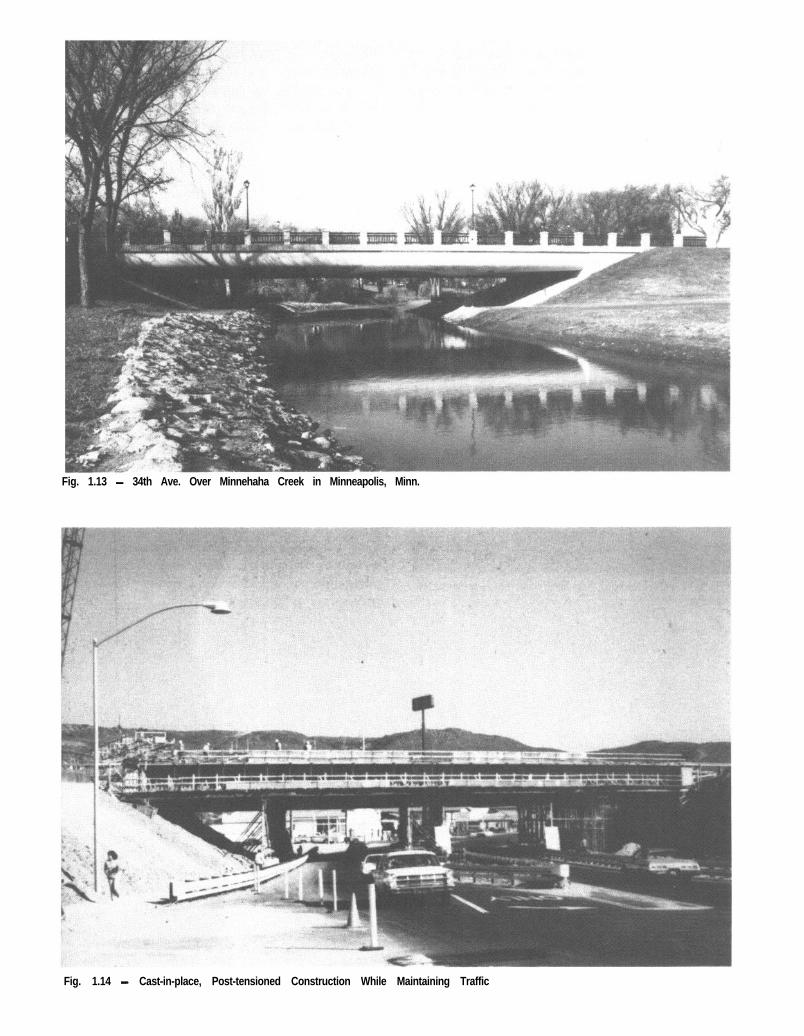
Fig. 1.13 - 34th Ave. Over Minnehaha Creek in Minneapolis, Minn.
Fig. 1.14 - Cast-in-place, Post-tensioned Construction While Maintaining Traffic

CHAPTER 2
POST-TENSIONED CAST-IN-PLACEBOX GIRDER BRIDGES CONSTRUCTED
ON FALSEWORK
This chapter contains design examples illustrat-ing both the preliminary and final design of asingle span and two-span post-tensioned cast-in-place box girder bridge. The design computationsare in accordance with the 1973 AASHTO Speci-fications*,’ ’ and all applicable Interim Specifi-cations.
Design aids which facilitate the preliminarydesign are included as well as examples presentingalternate methods for calculating long term lossesand secondary moments. A discussion of the effectsof frame shortening due to post-tensioning forcesand some typical earthquake details are alsoincluded.
2 .1 PRELIMINARY DESIGN
2.1 .l Design Parameters
Experience has led to the following preliminarydesign parameters:
Depth to Span Ratios (Relationship betweendepth to span ratios and the post-tensioningrequirements can be seen on graphs in Sec. 2.1.2)
One and two span structures:Depth
= 0.04 - 0.045’ Span Length
Mu Iti-span structures:Depth = 0.035 - 0.04
’ Span Length
Haunched structures at pier:
Depth= kO.048
Span Length
Haunched structures atCenterline Span:
Depth= 20.024
Span Length
Stem Thickness: 12” typical and optionallyflared near anchorages to provide end blocks forthe tendon anchorages.
Minimum Top Slab Thickness: 6” or l/16 of the
*Superscripts refer to references listed at the end of the chapter.
clear distance between the girders whichever isgreater.
Minimum Bottom Slab Thickness: 5%” or l/16 ofthe clear distance between the girders whicheveris greater.
Girder Spacing: Nominally 8’ with slab over-hangs equal to about one-half of the girder
spacing. Transverse post-tensioning of the topslab makes possible much larger web spacings.
2.1.2 Tendon Requirements
The approximate amount of post-tensioningsteel required can be determined from the graphsshown by Figs. 2.0 thru 2.5. By entering thegraph with a known span length and an appropriatedepth to span ratio (D/L), determined from thedesign parameters in Sec. 2.1 .l, the requiredamount of post-tensioning steel per square footof bridge can be read from the ordinate. Alsothe required concrete strength is indicated by thedashed lines.
These graphs were developed on the computerassuming the parameter listed on each and basedon HS20 loading with zero allowable tensilestress. However, the graphs can be used for pre-liminary design purposes when an allowabletensile stress of m is specified by using 85%of the post tensioning steel requirements indicatedfor simple spans and 75% for multiple spans.This procedure is illustrated in Sec. 2.2 and 2.3.
A large majority of the bridges of this typehave been built with tendons made of 7-wireASTM A416-74 Grade 270-X+ stress relievedstrand ducted in galvanized semi-rigid conduit.The number of strands per tendon should be leftto the discretion of the post-tensioning supplier.
The table below shows some typical strandtendons:
Working Force atNumber of Size of Approximate Stress
Strands D u c t Level 0.6 f: (KIPS)
9 - 1 2 2-518” 223-29613-18 3 ,, 322-44619-24 3%” 47 l-59525-31 4” 620-768
Larger tendonsare available for special applications.
The following table gives recommendations forstem thickness and anchorage space requirements:
1 1

FOR ALLOWABLE TENSION OF mUSE 85% OF PRESTRESSING STEEL VALUES SHOWN
PAN B O X G I R D E R
1 0 0 200SPAN LENGTH - FEET
CIP PRESTRESSED @OX GIRDERPRESTRESSING STEEL
H S 2 0
Fig. 2.0
1 2

1 0
9
8
IFOR ALLOWABLE TENSION OF 64/f,,USE 75% OF PRESTRESSING STEEL VALUES SHOWN
2 S P A N B O X G I R D E R
w/ equal spans
-t D- = 0.030 to 0.050
-t L
1 p = 0.25 K = 0.0002
100 200 300
SPAN LENGTH - FEET
CIP PRESTRESSED BOX GIRDERPRESTRESSING STEEL
HS20
Fig. 2.1
1 3

FOR ALLOWABLE TENSION OF mUSE 75% OF PRESTRESSING STEEL VALUES SHOWN
10 .I
314 L“A
3 SPAN BOX GIRDERWI 3/4L e n d svans
+ = 0 . 0 3 0 t o 0 . 0 5 0
Ha j.l = 0 . 2 5 K = 0.0002 f’s = 270 ksi
9
8
, , , , , , ,i i -t+--+++ +-+t- + ’ C d”“”
200
SPAN LENGTH - FEET
CIP PRESTRESSED BOX GIRDERPRESTRESSING STEEL
HS20Fig. 2.2
1 4

1 0
9
a
7
6
FOR ALLOWABLE TENSION OF cPRESTRESSING STEEL V,USE 75% OF 4LtiEi SHOWN
A A3 S P A N B O X G I R D E R
w/ equal spans+= 0.030 to 0.050
p = 0.25 K = 0.0002 f’ s = 270 ksi
0 100 200 300SPAN LENGTH - FEET
I
L/
CIP PRESTRESSED BOX GIRDERPRESTRESSING STEEL
HS20Fig. 2.3
1 5

8
6
FOR ALLOWABLE TENSION OF mUSE 75% OF PRESTRESSING STEEL VALUES SHOWN
4 SPAN B O X G I R D E R
--!Ip s i
! j i jI I ! !
I I !1
I I ! i i
1 0 0 200 300
SPAN LENGTH - FEET
;.,
CIP PRESTRESSED BOX GIRDERPRESTRESSING STEEL
HS20Fig. 2.4
1 6

an
FOR ALLOWABLE TENSION OF 6&-USE 75% OF PRESTRESSING STEEL VALUES SHOWN
4 S P A N B O X G I R D E R
w/ 314 L end spans
8
6
11 0 0 200 300
SPAN LENGTH - FEET
CIP PRESTRESSED BOX GIRDERPRESTRESSING STEEL
H S 2 0
Fig. 2.5
17

AnchorageSize
ReauirementsKips Per Girder S t e m Width Height
I,Pr” “Pi&’ Thickness (In.) (In.)
0- 800 O-1000 1 2 ” 2 7 2 7800-1200 1000-1500 1 2 ” 2 7 4 1
1200-1600 1500-2000 1 2 ” 2 7 5 41600-2000 2000-2500 1 2 ” 2 7 682000-2800 2500-3500 1 2 ” 2 7 812800-3200 3500-4000 1 2 ” 2 7 893200-4000 4000-5000 1 2 ” 2 7 105
“Pf” - applies to simple spans.“Pi.& ” - applies to continuous structures.
preliminary design location of the tendon profile,the tendon center of gravity for all practical ten-don and duct configurations is presumed in ac-cordance with Fig. 2.6. The “D” dimension isgiven by Fig. 2.7 for simple span bridges, and byFig. 2.8 for continuous bridges. A range of “D”values is given for simple span bridges to permitflexibility in the final details selected for the post-tensioning tendons. In developing the “D” valuesgiven in Figs. 2.7 and 2.8, the tendons were con-sidered to be offset within the ducts (the “2”value) for various duct sizes as follows:
Duct Size Z
3” OD and Less ?4Over 3” OD to 4” %Over 4” OD 1 ”
2.1.3 Tendon Location
The location and size of the post-tensioningforce must be assumed for preliminary design.The tendon force may be determined in accord-ance with the provisions of Section 2.1.2. Depend-ing primarily on the magnitude of this force,the tendons may be installed in webs in ducts ofvarying sizes as discussed in Section 3.1.2. For
The above procedure for location of the tendonprofile is illustrated in Sections 2.2 and 2.3.
2.1.4 Friction
The friction characteristics of semi-rigid conduithave been extensively investigated by the Califor-nia Division of Highways. The table below shows a
D u c tSize &
Structure Type
Northwest Connector 2%
Bridge #53-l 907 A
12/80 Separation 2 %
Bridge #23-16L A
Telegraph UC. 2 %Bridge # 3 3 - 4 1 3 R A
Sand Hill Rd. O.C. 2-518
Bridge #35-07 B
Del Paso Park Sep. 2-518
Bridge #24-193R C
C a l i f o r n i a Aquaduct 3 %Bridge #50-323 D
“R” Street U.P. 3%
Bridge #24-211 D
Eel River Br. R&L 4%
Bridge #4-l 55 E
No. ofTendonsTested
1 5
8
7
8
1 2
7
1 4
6
Average
Ave. Total M e a s u r e d AverageTendon Angle Ave. Force Calculated
Change for Tendon Live D e a d ForceTendons Tested Length E n d End Dead End
1.34 radians 394 3 7 2 250 2 4 6
0.99 radians 392 3 7 2 280 269
0.37 radians 273 372 3 2 4 320
1.21 radians 5 5 3 300 2 0 2 199
0.93 radians 5 4 8 300 251 2 1 3
0.84 radians 394 590 441 4 3 2
3.67 radians 418 682 289 2 5 1
0.76 radians 698 960 801 690
18

C.G.
t
This orrongement assumes that a\\main top bent cap reinforcementwill be located in this area. Widentop flange if necessary.
\I
. -/ \ - - - -
f
A
\/
-prest ressing force’
“K” -varies depending on location of deck or bent reinf. steel“0” -see “D” charts
-r /C.G. prestressing force
4V2” m i n . ,-z
/ 3lo
i
Fig. 2.6 - Guide for Assuming the Center of Gravity of Steel
19

181716I5I4I3I2
‘;; II
2 I O: 9
== 8
0
“D” CHART FOR SIMPLE SPANS
//’
/’
/yMaX.“D”-tir
I I I I I I I I I I I I I I I I I I I I I I I I I I I I I
111111~11~~~~~~~~~~~~~“~~“’I 5 0 0 1000 1500 2 0 0 0 2 5 0 0 3 0 0 0 3 5 0 0 4 0 0 0 4 5 0 0
P, (kips /girder)
I8I7I6I5I4I3I2I IIO
9
8765432
I
0
Fig. 2.7
“D” CHART FOR CONTINUOUS SPANS
5 0 0 IO00 1500 2 0 0 0 2 5 0 0 3 0 0 0 3 5 0 0 4 0 0 0 4 5 0 0P jack (kips /girder)
Fig . 2.8
2 0

summary of friction tests. These tests were con-ducted on a representative portion of the post-tensioned box girder highway structures con-structed in California each year. The tests weremade by having a load cell at each end of a tendonas the tendon was stressed from one end.Calculated force at the dead end is based on P =0.25 and K = 0.0002.
Duct descriotion:A = 2%” diameter duct made from 24gage,
galvanized material and seamed with acontinuous longitudinal resistance weld.
6 = 2-5/8” diameter duct made from 26gage,galvanized material and seamed with alongitudinal interlocking joint.
C = 2-5/8” diameter duct made from 26gage,galvanized material and seamed with alongitudinal interlocking joint.
D = 3%” diameter duct made from 24gage,galvanized material corrugated and seamedwith a helical interlocking joint.
E = 4%“ diameter duct made from 24gage,galvanized material corrugated and seamedwith a helical interlocking joint.
The tests plainly show that the friction valuesp = 0.25 and K = 0.0002 are realistic and perhapsconservative for large tendons. These frictionvalues will be used for the design examples.
2.2 SIMPLE SPAN EXAMPLE
2.2.1 Section Properties
42 x .625 = 26.25 x 6.19 = 162.48
‘/2 x 3.83 x .33 x 2 = 1.26 x 5.76 = 7.28
5x 1 .0x5 .39 = 26.99 x 3.18 = 85.83
34.33 x .477 = 16.38 x .24 = 3.93
Area = 70.88 Ft.* 259.52
C.G.C. = TT = 259.52/70.88 = 3.66 Ft. frombottom.Moment of Inertia
Top slab42 x .6253 = .854 +
1 226.25 x 2.53* = 168.88
Hau riches2 x 3.83 x .333 =
.Ol +3 6
1.26 x 2.1* = 5.57
Webs5 x 1 x 5.3g3
= 65.54 +1 2
26.99 x .48* = 71.76
Bottom Slab34.33 x .4773
= .310 +1 2
16.38 x 3.42* = 191.90
I = 438.11 Ft4
Section Mod. S, = 438.1112.84 = 154.26 Ft3Section Mod. Sb = 438.1 l/3.66 = 119.70 Ft3
r* = I/A = 438.1 l/70.88 = 6.18 Ft*
t
4’-4” 8’-4” 8’- 4” 8’-4” f3’-4” 4 ’ -4”4 *e *4 *4 *4 *4 *
TYPICAL SECTION
L = 162’+ \
SIMPLE SPAN EXAMPLEFig. 2.9
2 1

MStress Coeff = f, = - =
1000 x M
S t 144 x 154.26
= 0.0450 M
MStress Coeff = f, = - =
1OOOxM
Sb 144 x 119.70= 0.0580 M
(Stress in PSI, M inFt-KIPS)
2.2.2 Design Moments
Dead Load = 70.88 x .75 = 10.63
Diaphragms & Fillets = .03
W = 10.66K/Ft
M _ 10.66 x 1622D - = 34,970 Ft-K
8
Live Load Distribution
S SLL/Girder = - = -
2x7 14Equivalent for Entire Structure =
Web Spacing x No. Web Width=-1 4 1 4
LL Distribution = 42 = 3.01 4
Impact =50 50
= = 0.174L+ 125 162 + 125
M = 3.0 x 1.174 x 2830 = 99671K\AASHTO Tables)
MD + ML, = 34,970 + 9967 = 44,937 FT-K
2.2.3 Post-Tensioning Requirements Stresses atMidspan Due to LL + DL
f =t 0.0450 x 44,937 = 2022 PSI(Compression)
f, = 0.0580 x 44,937 = -2606 PSI(Tension)
Allowable Stresses for f: = 3500 PSI
Compression = 0.40 ff = 1400 psiTension = 6JT = 355 psi
Approximate P/T required from Sec. 2.1.2= .85 x 4.7 = 4.0 #/Ft2
#/Lin Ft or-0.520
= 323-X” @Strands/Bridge
Approximate Pf =323 x .6 x .153 x 270
5= 1601 K/Girder
From Fig. 2.7 Min “D” = 3%”
The maximum distance from the CGS to thebottom fiber (x) = 3% + 4% = 8”Therefore e = 43.92 - 8 = 35.92 I’/12 = 2.99’
Post-Tensioning Force and Cont. Strength Required:
Bottom f, - f,, = 2606 - 355 = 2251 psi
fb
Pr = 8294K
=P,+P,e = 2251A %
1000 Pf+ Pf x 2.99 x 0.058 = 2251
144 x 70.88
Assumed P, = 5 x 1601 = 8005KCheck assumed e
Pf = 8294/5 = 165gK/GirderMin “D” = 3-5/8” ir, 3%” Therefore tendons
will fitTop Stress Due to P/T
f 8294 x 1000= -t 8294 x 2.99 x 0.045
144 x 70.88= -303 psi
Therefore Final Top Stress = 2022 - 303= 1719 psi
Cont. Strength Required =1719- = 4300 psi
.4
The design could be recycled for f; = 4300 psiwhich could reduce the required Pf by about 1%.Number of ‘/“(I-270 KSI Strands Required:
Assume Loss = 33000 psiAllowable Strand Stress Before Loss = .7 x 270
= 189 KSI
f, = 189-33= 156 KSI
Number of Strands =8294
5x 156x.153
= 69.5” strands per web.
Pf total (before losses) =69.5 x 5 x 189 x .153 = 10,049K
*The post-tensioning supplier will furnish Standard tendons.
2 2
--
4.0168
x 4 2 = 168

2.2.4 Required Cont. Strength at Stressing
The required ultimate strength of the concreteat the time of stressing will be governed by eitherthe initial flexural stresses or the bearing stressesinduced by the tendon anchorages. A discussionof the anchorage bearing stresses is included inSec. 2.8. The compressive stresses in the structure,other than in the immediate area of the anchorage,are limited to 55% of the ultimate concrete strengthand the tensile stresses are limited to 7.m.
Dead Load Fiber Stress at Midspan:
TOP f, = 34,970 x 0.045 = 1574 psi(Camp)
Bottom f, = 34,970 x 0.058 = 2028 psi(Tens)
Prestressing Fiber Stress at Midspan Before Losses:
Top f, =1000x 10049
- 10049 x 2.99144 x 70.88
x .045 = -368 p s i (Tens)
Bottom f, = looox 1o04g+ 10049x2.99144 x 70.88
x -058 = 2728 p s i (Comp)
Net Stresses:
Top f, = 1574 - 368 = 1206 psi (Comp)Bottom f, = 2728-2028 = 700 psi (Comp)
Required Strength at Stressing:
1206- = 2193 psi
.55Anchorage bearing stresses will govern.
2.2.5 Ultimate Moment
Ultimate moment requirements normally do notcontrol simple span design. The procedure tocheck ultimate moment capacity and typicalshear steel calculations are shown for the twospan bridge and are not included in this example.
fashion. To find the net deflection at a’ particularpoint in time, consideration must be given to thesize of prestressing force acting. For instance,to compute initial deflections, the initial pre-stressing force should be used and while calculatingultimate deflections, the final prestressing forceshould be used.
The friction effects can generally be neglectedin the design of a simple span structure. However,friction calculations should be made by the post-tensioning contractor and submitted on his fabri-cation drawings. See Sec. 2.3.5 for the calculationprocedure.
2.3 TWOSPAN CONTINUOUS EXAMPLE
The design and details of continuous prestressedmembers differ from simple beam design in thatsecondary moments are introduced as the memberis stressed. Also, the tendon path is usually longerand has more angle change so that friction andanchor seating losses must be considered in thedesign calculations. The procedure of designillustrated by thisexample accounts for the second-ary moments, friction losses and anchor seatingl o s s e s .
This structure will be designed as a unit withlive load applied which is equivalent to individualgirder design.
2.3.1 Properties
Midspan Properties (From Sec. 2.2.1)
A = 70.88 Ft2C G C = 3.66 FT From BottomI = 438.11 FT4
St = 154.26 FT3
Sb = 119.70 FT3Stress Coeff. f, = 0.0450 M”Stress Coeff. f, = 0.0580 M’
‘Stress in PSI; M in FT-K IPS
Properties at Bent: (See Fig. 2.10)2.2.6 Deformations & Friction
Area and CGCThe amount of shortening as a result of post-
tensioning approximates a total (elastic + plastic+ shrinkage) of 1” per 100’ of structure. On thisstructure, provision should be made at one abut-ment to allow the movement due to shortening.
Deflections due to dead load and prestressingshould be calculated separately in the normal
42 x .625 = 26.25 x 6.19 = 162.48
% x 3.83 x .33 x 2 = 1.26 x 5.76 = 7.28
5 x 4.875 x 1 = 24.38 x 3.43 = 83.61
34.33 x 1 = 34.33 x .50 = 17.16
Area A = 86.22 FT’ 270.53
23

1
t I’-O”@ bent)
42’- 0” 4
4’-4” 8’ - 4 ” 8’- 4”4 4 w4 +
TYPICAL
t+
8’-4”t4
&4”fi
SECTION
4’ - 4”t 3
162 ’ I
I 312’ I
SPAN ARRANGEMENTFig. 2.10
270.53CGC = - = 3.14 Ft. from Bottom
86.22
Moment of inertia:
Top Slab42 x .6253 = .854 + 26.25
1 2x 2.53* = 168.88
Haunches2 x 3.83 x .333
36 =.Ol + 1.26
x 2.1* = 5.57
W e b s5 x 1 x 4.8753
= 48.27 + 24.381 2
x .29* = 50.32
Bottom Slab 34’33 xl3 = 2.86 + 34.331 2
x 2.64* = 242.13
I = 466.9 FT4
st
= 466.9- = 138.96 FT3
3.36
sb
_ 466.9- - = 148.69 FT3
3 . 1 4
Stress Coeff. = f, = fi =1 0 0 0 M
St 144 x 138.96
= 0.0500 M”
Stress Coeff. = f, = A!!-=1 0 0 0 M
Sb 144 x 148.69= 0.0467 M”
*Stress in PSI; M in FT-KIPS
2.3.2 Design Moments
Dead Load = 70.88 x .15 = 10.63
Diaphragms & Fillets = .03
w = 1 0.66K /FT
Live Load Distribution
LL s S-=-=-Girder S x 7 14
WidthFor entire structure use -
1 4
LL Distribution = 42/14 = 3.0 LanesNo multiple lane live load reduction is applicable
because the computed distribution is an equivalentgirder loading.
Design Moments (From Moment Envelopes):
.4Span 1 .6 Span 2
MD = 15 151 lK
ML = 6;980 lK
MD = 19,940 lK
ML = 7,597’K
MT = 22 131 lKI MT = 27,537 lK
2 4

Center-line Bent 2
MD = -34,078 ’ KML = - 9,230 lK
Due to the presence of secondary moments, themost efficient location for the low point alongthe cable path is near 0.5 L in a two span structure.For this example 0.5 L will be used.
MT = -43,308 lK
2.3.5 Friction Losses
2.3.3 Preliminary Post-Tensioning Requirements
From Fig. 2.1 in Sec. 2.1.2 for 162 Ft. SpanP/T Req’d = .75 x 4.2 = 3.15 #/Ft242 x 3.15 = 132.3 #/Ft of Bridge132.3/0.52 = 255 Strands or 51 Strands per
Girder
fd = 3900 psi
P, = 51 x .75x 270 x .153 = 1580 K/GirderFrom Fig. 2.8 Sec. 2.1.3
“D” = 5%”
Minimum distance from the C.G. of the prestress-ing force to the bottom surface of the bridge = 5%”+ 4%” = 10”
Minimum distance from the C.G. of the pre-stressing force to the top surface of the deck = 5%”+ (7%” - 1”) = 12”
Inflection pointsalong the cable path are located0.1 L from the bent. This location results in areasonable radius of curvature for placing semi-rigid duct and maintains the forces on duct ma-terial within acceptable limits during stressing.
Angle change in Span 1 (in Radians):
AB =2 x 2.83
= .075 (True for small angles)7 5
BC = 2 x 3.74= .125
60
CD = 2xmg3 = -12515 -
ff = .325
(Note: BC & CD will always be equal)
Angle change in Span 2:
DE = 2xg3- = .11516.2
EF = 2 x 3.74
64.8 =.115
FG = 2x 2.83 = .07081 -
a = 0.300
(&abut- I c bent-2 c abut-3
162’162’)f-II -s -2-s -2 -e-eaqaq+ I+ I NN
1L1L-- Parabola\Parabola\
I +I 4 4 I4 I
75’75’-ii -ii-ii -ii -ii -2-ii -2
. cd 64.8’. cd 64.8’ 81’81’++ 60’ c\i : 15’ 16.2’60’ nj : 15’ 16.2’,-tt+,-tt+ flfl
A
.5L,.5L,
li
.4L,.4L, AL, .IL*AL,, .IL*
60;
.4L2.4L2
k
.5L,.5L,
hA B cb i i i;TENDON (C.G.S.) PROFILETENDON (C.G.S.) PROFILE
Dimensions “a” & “b” can be found because the inflectionDimensions “a” & “b” can be found because the inflectionpoint of two parabolas l ies on a straight l ine.point of two parabolas l ies on a straight l ine.
a = g x 4.67 = 3.74’a = g x 4.67 = 3.74’
b = % x 4.67 = 3.74’b = % x 4.67 = 3.74’
Fig. 2.1 I
2 5

Span 1
KL+/.m = 0.0002 x 150 + 0.25 x .325=O.ll
pj = p, x &KL + w)= p x $."= ?:l?SP,
Tension at bent = 89.6% of Pi
Span 2
KL + /.RY = 0.0002 x 162 + 0.25 x .300= 0.107
pi = pxe.lo7
= 1.113Tension at bent = 89.8% of PjUse Tj at bent = 89.8% Pj
Anchor Set:The effect of anchor set on the cable stress is asfollows:
f
j1cnchcr I
r -1
Fig. 2.12
A f = Change in stresses due to anchor set(KS11
X = Length influenced by anchor set (FT)d = Friction loss in length L (KSI)L = Length to a point where loss is known
(FT)AL = Anchor set (IN)E = Modulus of elasticity (KSI)
Average unit stress = E x (unit strain)
Af-= E*12x
A; =c6x
By Similar Triangles
X L 2dx- =- or Af = -Aff2 d L
EAL 2dxTherefore Af = - = -
6x L
J E(AL)LX=
12d
*The anchor set may vary with different post-tensioning systems.Anchor set valuer may be obtained from the post-tensioning mater-ials suppliers.
Stress variation along tendon:f: = 270 KSI assume AL = 5/8”*f =JACK 270 x .75 = 202 KSI
fj @ Bent = 202 x .898 = 1 8 1 KSId = 202 - 181 = 21 KSI
Span 1
x JT = 104’
104-= .7L,1 5 0
Af =2dx= 2x21 x 104=29KSI o r
L 1 5 0
Af= 2g = .14Pi270 x .75
Soan 2
108- = .7 L,162
A f = 2x21x1o8 = 28KSI o r162
Af= 28270 x .75
= .14 Pj
Again assume long term losses = 33 KSI
AfLT =3 3
270 x .75= .16 Pj
By assuming the jacking force, Pi, to be unityat a stress of 202 ksi, the force along the cableand the losses can be expressed in terms of Pi.Also, the internal moment due to the prestressforce being applied at an eccentricity can beexpressed in terms of the same Pj. The long termlosses are assumed to be 33,000 psi in accordancewith Article 1.6.7(B) of the AASHTO Specifica-tions. The tendon force diagram is shown in Fig.2.13.
Secondary moments are combined with theP,e moments to provide the total moment effectof the post-tensioning. The secondary momentscan be computed by several methods such asslope deflection or by influence coefficients. Themethod contained in this example utilizes theinfluence coefficients appearing in the Appendix.Calculations based on moment area or slopedeflection procedures are presented for a threespan bridge in Section 2.5.
The P,e moments and the secondary momentswere computed neglecting the flare in the bottomslab. No appreciable error is introduced with this
2 6

1.00 Pj
79
cabut-I c bent-2 c abut-3
/Force in tendon I Ibefore seating loss
-Long term losses
108’
\Final force in tendon(Pf) in terms of Pj
TENDON FORCE DIAGRAM
I, I I 1 I I I I I 1 I I I I 1 1 I I II I I I I I I I I I I I I , I I I I , i
Location 7 .I -2 -3 .4 .5 .6 -7 -8 .9 N .I .2 .3 .4 .5 .6 .7 .8 .g Mc I I2 ‘c al *
0z
ul 3 s
I .OO Pj
-86 Pj
.7OPj
Fig. 2.13

L, = 150’ L2 = 162’
tn t
Fig. 2.14
procedure since the increased “e” and increased“I” tend to compensate for each other. The flareproperties are used for computing the dead loadand live load moments and the stresses.
2.3.6
Span Id =c =
we1
Wl
Compute Secondary MomentsSee Appendix Section A.1
2.834.67
2Pc 2 x x 2.83=- = .72P,
a: L: .52 x 15022Pc
= (l-b, ) (l-b, -a, )L:
= .00072 Pi
= 2 x .76Pi x 4.67
(l - .5)(1- .5- .1) 150* = -oo1577 pi2.3.7. P,e Diagram
Span I Id = 283’c = 4.67’
2 ’ ‘72pj ’ 2’83 = .000621 p,we* = -.52 x 1622
1
Wl =2 x .76P, x 4.67
(l - .5)(1- .5- .1) 1622= .001352 Pj
Total M = L.022513 x .00072 Pj + .019657 x.001577P, + .024809 x .000621 Pj+ .028413 X .001352 PjI 1622
= 2.651 PjlK
Total M = Mprimary + Secondary= P,e + M,
MS = 2.651 Pj - -74 Pj X 1.84= 1.289 Pi
c abut-l c bent -2 Q abut-2
Location 0 . . .- eJ f Q ** ‘n co b Q) 0 0. . . . . . 7 ‘v “. . . . . . . .*flocobcaD mo
2 8

c abut-l c bent-2 ’ Qabut-3
Secondary moment
Moment coefficient (eff. Pfe 1
Pje 0
Mom. ocoeff.
EFFECTIVE Pte DIAGRAM
Fig. 2.16
seDL+LL+l ‘s-.
I , \ 1 I 1 II I I 1 I I 1 IL . I .2 3 . .4 .5 .6 . . .5 .6 .7 .8 .9 I.0
q abut-l k abut-3 -4
TOP FIBER DEADLOAD+LlVE LOAD+IMPACT STRESSESFig. 2.17

‘I *
.i .2 .j .4 .S .S .i\.sn Ii3 .I
I/, I.ij/ .3 .4 5 . .6 .7 ,0 .9 To
cabut-2 --I
BOTTOM FIBER DEAD LOAD+LlVE LOAD +IMPACT STRESSES
Fig. 2.18
Solution for Prestressing Force:
As in simple-span prestressing, the prestressingforce must be large enough to bring the concretestresses within the allowable limits.
For fd = 5,000 psiAllowable Tension = 424 psiAllowable Compression = 2,000 psi
The stresses in the concrete due to the pre-stressing is computed with the following equation:
f=!+EA I
These terms can be written:
Pi x Force Coeff.+ Pi x Mom. Coeff. x Stress
AreaCoeff. = f,
Point of maximum tension in the top fiber isat the centerline of Bent 2 = 1849 psi. The re-quired change in stress due to post-tensioning =1849 - 424 = 1425 psi.
1000 x .74 Pi+ Pi x 2.65 x .0500 = 1425
86.22 x 144 ’Pi = 7418K (Governs)
7418/5 = 1484 K/Girder Assumed 1490 K/Girder
Check “D” From Fig. 2.8“D” = 5%” Tendon will work at the estimated
eccentricity
Check bottom fiber .6 Span 2P/T Required = 1597 - 4 2 4 = 1173 psi
1000 x .74 Pi+ 1.49
70.88 x 144Pi x .0580 = 1173
Pi = 7381K
Check bottom fiber .4 Span 1P/T Required = 779 - 424 = 355 psi
1000 x .74 Pi+ 1.49 x .0580 = 3 5 5
70.88 x 144Pi
Pi = 2233K
The stresses due to post-tensioning are plotteddirectly on the stress diagram already constructedfor DL + LL + I. It is important to notice the signconvention used in plotting the stresses. The signconvention used for stresses due to prestressingshould be opposite those used for DL + LL + Istresses. The final stresses are found by scalingbetween stress lines.
The stress plots show that the required ultimatestrength of the concrete due to compression in thebottom slab at the bent is 3370 psi. The designertherefore has a choice of designing the structurefor a lower strength concrete and somewhat morepost-tensioning steel or a higher strength concretewith inherently better durability characteristicsand a little less post-tensioning steel.
30

TOP FIBER COMBINED STRESSES
Fig. 2.19
p’/kDL tLL+I__-------
.i .4 .5 .6 .7 .0 .9 I3 .I 2
cabut-3
Req’d ult. cont. strength1348 +.4=3370 psiuse 3500 psi
BOTTOM FIBER COMBINED STRESSES
Fig. 2.20
3 1

I 2.3.8 Ultimate Load Considerations
AASHTO Specifications require that post-tensioned members be designed by the elasticmethod and their capacity for ultimate loads beverified for a factored ultimate design moment(Mu). Structures are proportioned for shear onthe basis of ultimate load considerations only.
Ultimate Design Moment = M, = 7 (DL+5/3
(LL + I)) + M, where $I = .9 for cast-in-place con-struction
Check at 0.4 pt. Span 1Applied M, = 1.44 [ 15151 + 5/3(6980)1 +
(51 x 8248) = 42,776 lK
Secondary Moment= .51 Pi
Capacity:
f”S”= f; (1 0*5p*fi )
f,’A”
P * =s A : =7418
= 36.6 in2b d .75 x 270
P * = 36.6= .00109
42x5.55x 144
f Q _ 270(, _ 0.5 x .00109 x 270S” - 1
5f:” = 262 KSI
Locate NA:The NA will fall in the flange if the flange thick-
ness is greater than1.4dp*f:,lf; = 1.4x5.55x12x.00109x
26215 = 5.32 in < 5.75”The neutral axis falls in the flange therefore the
section is considered rectangular.
M, (Provided) = A: f:,d (1 -.6 p*f:,
)f :
= 36.6 x 262 x 5.55 xx .00109 x
(1 - .6 262 15
= 51 3961K > 42 7761KCheck maximum stell percentage:
pf”* su 2 6 2= . 0 0 1 0 9 x - = .06 < .3
f d 5Steel will yield before concrete fails.Compute cracking load and check minimum
steel:Rupture Stress = 7.5 fl
= 7.5d-
= 530 PSI
f CR =Pj x Force Coeff
A+ Pj x Mom. Coeff. x
Stress Coeff. - M,, x Stress Coeff.
- 5 3 0 =1000x8248x.74 + 8248x14gx
144 x 70.88.0580 - MCR x .0580
I
M C R = 31,7381K= 38,0851K < 52,3451K
11.2 M,,
A: above minimumCheck ultimate moment at Bent:
Applied M, = 1.44 [34,078 + 5/3 x 92301 -1.29 x 8248 = 60,584’ K
Secondary Moment= 1.29 Pj
Moment Capacity:
f:” =f,*(l-.5p “f:-)
f d
P * =36.6
= .0013534.33 x 5.5 x 1 4 4
f:, = 270 (1 - .5 x .00135 2 7 0x)
5= 260 KSI
Locate NA1.4 dp*f:,/f; = 1.4 x 6.01 x 12 x .00135 x
262/5 = 7.24” < 12”
NA in Flange
M, (Provided) = A: f& d(1 - -@*fit )
f := 36.6 x 261 x 5.5 x
(1 -.6 x .00135 x 262
15
= 50,309’ K < 60,584’ KMild steel is required.Use Grade 60 steel, fy = 60,000 psiWith NA at 7.24” in. from the extreme fiber,
the center of compression is about 3.62” up fromthe bottom of the box, and the center of gravityof the mild steel about 3.5” from the top surface.
Resisting M = 60 x A, x (6.5 - .30 - .29)
A5
= 60,584 - 50,309
60 x 5.91A, = 29.0 in2
Use 29 #9 BarsA, = 29 in2Check steel percentage:
P”f&Prestressing steel: - =.00135 x 262
f : 5= .0707
3 2

c bent
.I .2 .3I I 1I
7.5’ 4 .86 ’-
ULTIMATE MOMENT DIAGRAM NEAR BENT
.8 .9q bent
I *
A pplied M,
Resisting M,with 594” slab
7.29 Min. flarek r
BOTTOM SLAB FLARE LENGTH DIAGRAM
Fig. 2.21

P fsyMild steel: - =29 x 60
c 34.33 x 12 x 66 x 5= .0707 + .0127 = 6834 < .3
Therefore, the steel will yield before the con-crete ruptures.
To determine the cut-off point for mild steeland the length of flare required, plot the negativeportion of the ultimate moment envelope.
Span IPt..7 M, = 1.44 [ 1330 + 5/3 x (-3575.24)] + .90 x
7418 = +10.81K.8 M, = 1.44 t-8074 - 5/3 x 40861 + 1.03 x
7418 = -13,792.41K.9 M, = 1.44 [--19877 - 5/3 x 58471 + 1.16 x
7418 = -34,050.8Bent M, = -60,5841K.l M, = 1.44 [-18081 -5/3x54191 +1.16x
7418 = -30,437.4’ K.2 M, = 1.44 [-4882 - 5/3 x 33391 + 1.03 x
7418 = -7,403.VK.3 M, = 1.44 [5520 - 5/3 x 28861 + .90 x
7418 = +7698.61K
Ultimate capacity:At Bent
Resisting M, = 51,2381KWhen the ultimate moment is controlled by the
steel, it is nearly proportional to d.4.57
M, at 0.9 pt. Span 1 = - x 50,309
= 47’:02’ K
1 2.93M, at 0.8 pt. Span 1 = - x 50,309
= 256::ol’k
4.57M, at 0.1 pt. Span 2 = - x 50,309
= 4!‘:02’ k
M, at 0.2 pt. Span 2 =2.93- x 50,309
= 2:;“,,1’ K
Fig. 2.21 shows theoretical lengths of 7’-6” inSpan 1 and 4-10” in Span 2. Therefore, the mildsteel must be placed to these lengths plus theextension as required by AASHTO.
Flare Lengths:This design is based on the bottom slab flare
extending out 0.1 L from the centerline of thebent. The length required to provide adequateultimate moment capacity can be found at thistime.
Moving away from the bent, the slab thicknessis reduced while A, remains constant. At the pointwhere the normal bottom slab thickness is ade-quate, the NA usually falls in the web. By neglect-ing the small compression area in the web, theultimate strength based on failure in the concretecan be conservatively estimated.
The ultimate moment capacity varies along thespan because “d” changes. M, can be computedat any specific point using the minimum slabthickness and can be assumed to vary on a straightline between them. The required flare length canthen be found graphically using the ultimatemoment diagram as shown in Fig. 2.21.
Span 1At 0.8 pt.: t = 5%” d = 2.93”M, = 0.85 x 5 x 34.33 x 12 x 5.75 (2.93 - .24)
= 27,0811K
M,=0.85Q’bt(d- t/2)
Fig. 2.22
3 4

At 0.9 pt.: t = 5%” d = 4.57”M, = 0.85 x 5 x 34.33 x 1 2 x 5.75 (4.57 - .24)
= 43,591’K
Span 2At 0.2 pt.: t = 5%” d = 2.93”M, = 0.85 x 5 x 34.33 x 1 2 x 5.75 (2.93 - .24)
= 27,0811K
At 0.1 pt.: t = 5%” d = 4.57”M, = 0.85 x 5 x 34.33 x 1 2 x 5.75 (4.57 - .24)
= 43,591 lK
At Bent t = 5%” d = 5.50”M, = 0.85 x 5 x 34.33 x 1 2 x 5.75 (5.50 - .24)
= 52,954’ K
2.3.9 Shear
AASHTO Specifications will be used for deter-mining shear capacity, except that rather thanusing d = distance from compression face to thecentroid of the prestressing force, we will considerd = 0.8 total girder depth for the full length of thestructure. The cable shear will be the verticalcomponent of Pf. These assumptions generallyresult in a slightly more conservative design thanthe more complex procedure specified in ACI.
Applied Shear:Below are DL + LL + I shears from normal
analysis.Span Dead Load Shear (K)
N o . L e f t Right
1 572.3 -1026.7
2 1073.8 - 653.0
Span Live Load Shear Plus Impact (K)
No. Left End Midspan Right End
+ 92.51 2 4 1 . O -141 .9 -310.7
+ 139.02 318.7 - 72.4 -249.4
The secondary moments resulting from pre-stressing cause a change in reaction which affectsv a l u e s :
I‘
r
MAR = Change in Reaction = 5L
Span 1 : AR 1.289 7418x= = 63 7K
1 5 0
Soan 2: AR = 1.289 x 7418 = 5g OK
162Span 1
1.3v, = - [DL + 5/3(LL + I)1 @ = 0.85~
Abut 1V, = 1.53 [572.3 + 5/3 x 2411 + 63.7
= 1554K
Centerline SpanV, = 1.53 x 513 x 92.5 + 63.7
= 299.6KBent
V, = 1.53 [1026.7 + 5/3 x 310.71 - 63.7= 2299.4K
Span 2BentV, = 1.53 (1073.8 + 5/3 x 318.7) - 59.0
= 2396.6KCenterline Span
V” = 1.53 x 5/3 x 139.0 - 59.0= 295.4K
A b u t m e n t 3V, = 1.53 (653.0 + 5/3 x 249.4) + 59.0
= 1694K
Cable Shears:
Cable Force CableLocation Slope Coeff. P i Shear
Abut 1 .075 .70 7418 389.5 Span 1 0 .75 7418 0.9 Span 1 .125 .75 7418 695Bent 2 0 .74 7418 0.l Span 2 .115 .75 7418 640.5 Span 2 0 .75 7418 0Abut 3 .070 .70 7418 363
Concrete Shear ResistanceV, = nl80b’jd j = 0.90
Assume d = 0.8 x 78 = 62.4” jd = 56.2”
(12” Stem) V, =1 8 0 x 5 x 1 2 x 5 6 . 2 = 607K
1000
A = (Vu -Vc)sor 5
v = 1.8Avf;d”
1.8 f;d S
With #5 stirrups in five webs:A , = 10 x 0.31 = 3.1 in2/stirrup
v = 1.8 x 3.1 x 60 x 62.4 = 20,8925
S S
Ifs=9” V, =2321KIfs = 12” v, = 1741KIfs = 18” V, = 1161KIf s = 23” V, = 908K
Minimum stirrup area: (AASHTO)
3 5

1 OOb’sMin A, = -
fY
S Av fymax z-z 3.1 x 60,000 = 31 in
1 OOb’ 100x 12x5Maximum spacing allowed by AASHTO is three-
fourths the depth of the number.S max = .75 x 78 = 58.5”
However, the stirrups are also used as verticalties between the webs and the slab so this maxi-mum spacing may govern.
4 x thickness of the bottom flange = 4 x 5.75 =23 inches
(See Fig. 2.23 for stirrup requirements)
Deflections:
Deflections due to prestressing can be calculatedfrom the effective P,e/EI diagram using slope de-flection. As with simple spans, attention must bepaid to the level of the prestressing force at thetime at which the deflection is to be calculated.
Abutment details normally allow for movementto accommodate structure shortening.
2.4 CALCULATION OF LONG TERM LOSSES
Long term prestress losses may be calculatedaccording to the provisions of Article 1.6.7 (B)of the AASHTO Specification. The following isan example of the loss calculation for the twospan continuous structure in the design example.
The long term losses will be computed at thebent and at 0.6 pt. of span 2 which are the criticalpoints. Also, it is assumed that the bridge willbe constructed in one of the Midwestern Statesto determine the portion of loss due to the shrink-a g e .
2.4.1 Shrinkage Loss (SH)
S H = .8 (17,000- 1 5 0 RH)S H = .8 (17,000 - 1 5 0 X 70) = 5,200 p s i
2.4.2 Elastic Shortening (ES)
ES = 0.5 (E’f,-i,)Eci
E,i = 33 X(1501’5)Jw = 4.3 X lo6 psi
ES = 28X lo6 psi
From Fig. 2.13, the tendon force at the bent andat 0.6 Span 2 after friction, anchor seating and
elastic shortening losses can be estimated at about0.89 Pi. (ES approximately 0.01 Pi)
0.89 Pj = O-89 X 7418 = 6602 K
D L M o m e n t at 0.6 Span 2 = 19,940 FT-KM, at 0.6 Span 2 (Fig. 2.16)
= -51 X Pj = a51 X 7418 = 3783 FT-K
e a t 0.6 Span 2 (Fig. 2.15) = 2.71 F T .
Post-tensioning moment to calculate f,-ir at 0.6Span 2 = Pe - M, = M,,= 6602 x 2.71 3783-
= 14108 FT-K
P M,,e M.,efcir=-+---
A I I
fcir = 93.14 + 87.27 - 123.33 = 57.08 KSF
1000fcir = 5 7 . 0 8 X-
144= 396 psi
2 8 x 10⁶E S . 6 = 0.5 396 = 1289
4 . 3 x 10⁶p s i
Elastic Shortening Loss at Bent:DL Moment = 3 4 0 7 8 F T - KM, (Fig. 2.16) = 1.29 x 7418 = 9569 FT-Ke (Fig. 2.15) = 1 .84 FT
MP-3 = 6602 x 1.84+ 9569 = 21717 FT-K
M,,e b,efcir f + - - -
I
fcir = 6 6 0 2 + 217;;6xl;.84 _ 34y6;;.8486.22
1000fc i r = 3 4 . 9 3 x - =
144243 psi
2 8 x lo6E S 2 4 3 =B E N T = 0.5 7914 . 3 x 10⁶ p s i
2.4.3 Concrete Creep (CR, 1
Assume feds = 0 (conservative)
CR, = 12 fcir - 7 feds
at 0.6 Span 2
CR, = 12x396 = 4752 psi
3 6

--1 4 #5@23”
>#5@12”
I
4#5 @23”
‘Stirrup spacing
-#5@12”
NlI \ T 23”
Yu = AR +DL +LL+
/#5@23”\ -[7
t-
c abut-l
At tendon ends, decrease the stirrupspacing to V2 the theoretical maximumfor a distance “0” (in this case 6.5’) toreinforce for bursting stresses fromconcentrated loads at the anchor. t-
c bent-2
‘#5 @ 23”
1#5@12”
cabut-3 -
SHEAR DIAGRAM TO DETERMINE STIRRUP REQUIREMENTS
Fig. 2.23
at Bent
CR, = 12x243 = 2916psiproximately 5.1 percent reduction in tendonrequirements (8000/156,000 X 100 = 5.1 percent).If the design had not utilized allowable tensionof a, the calculated prestress losses would havebeen somewhat higher.
2.4.4 Relaxation of Prestressing Steel (CR,)
CR, = 20,000 - 0.3 FR - 0.4 ES - 0.2 (SH + CR,)
Note: FR applicable only where it reduces the ten-don stress below 0.70 f,’
at 0.6 Span 2Friction Loss = 0.04 x .75 f,’ = 0.03 f,’Pj - Friction IOSS = 0.75 f,’ - 0.03 f,’
= 0.72 f,’FR=O
CR, = 20,000 - 0.4 x 1289 - 0.2 (5200 + 4752)
CR, = 17494 psi
at Bent
F R = (0.70 - .90 x .75) 270 = 6.75 KSI
CR, = 20,000 - 0.3 x 6750 - 0.4 x 791
- 0.2 (5200 + 2916)
= 16035 psi
2.4.5 Summation of Prestress Losses
.6 Span 2 Bent
Shrinkage (SH) 5,200 5,200Elastic Shortening (ES) 1,289 791Concrete Creep (CR, ) 4,752 2,916Steel Relaxation (CR,) 17,494 16,035Total Prestress LossExcluding Friction 28,735 psi 24,942 p s i
Note the losses are less than the 33,000 psi as-sumed in the design, particularly at the bent whichis the point which controlled the required tendonforce. The design could be recycled with prestresslosses of 25,000 psi assumed at the pier with ap-
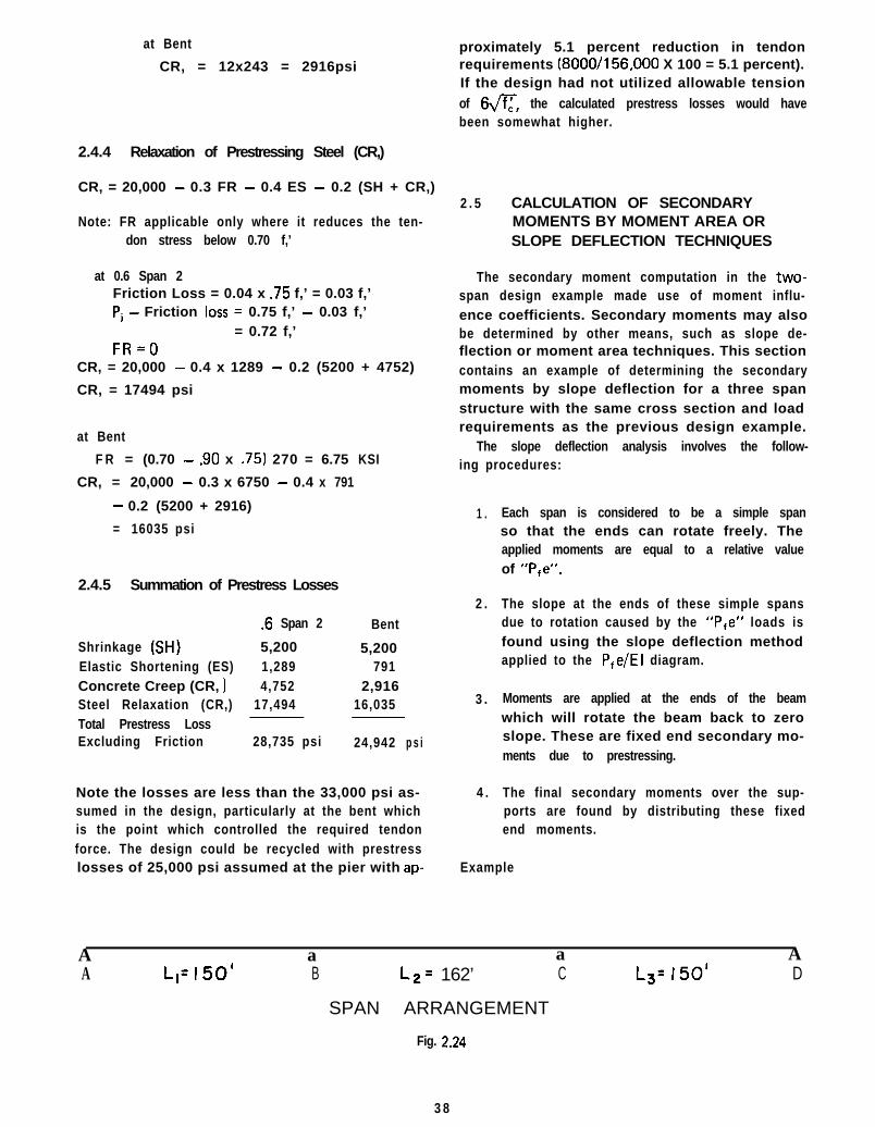
2 . 5 CALCULATION OF SECONDARYMOMENTS BY MOMENT AREA ORSLOPE DEFLECTION TECHNIQUES
The secondary moment computation in the two-span design example made use of moment influ-ence coefficients. Secondary moments may alsobe determined by other means, such as slope de-flection or moment area techniques. This sectioncontains an example of determining the secondarymoments by slope deflection for a three spanstructure with the same cross section and loadrequirements as the previous design example.
The slope deflection analysis involves the follow-ing procedures:
1 .
2 .
3 .
4 .
Each span is considered to be a simple spanso that the ends can rotate freely. Theapplied moments are equal to a relative valueof “P,e”.
The slope at the ends of these simple spansdue to rotation caused by the “Pre” loads isfound using the slope deflection methodapplied to the P,e/EI diagram.
Moments are applied at the ends of the beamwhich will rotate the beam back to zeroslope. These are fixed end secondary mo-ments due to prestressing.
The final secondary moments over the sup-ports are found by distributing these fixedend moments.
Example
A a a AA L1= 150’ B L2= 162’ C Ls= 150’ D
SPAN ARRANGEMENT
Fig. 2.24
3 8

a b
‘i
.85 PI
.69 PI
- E x 4.63 = 3.70’a - 75
64.8b =-8, x 4 . 6 8 = 3 .74 ’
Fig. 2.25
Q. abut-l C-bent 2 C-bent-3 C-abut-4
4 101.3’ _ _ 48.7’ L _ 81’ 81’ k
- - - - - - - - - - - -
.671 PjI I
.85 Pj
.69 Pj
IFig. 2.26
I-Q abu’t 4
L o c a t i o n 0
e 0
Pj .69
Pfe 0
8
-13
\c b e n t - 2 -4
he d i a a r a m‘Actual tenddn path
SPAN I Pfe D IAGRAM
.I .2 .3 .4 .5 .6 .7 .8 .9 I .O
I.01 1.79 2 . 3 5 2 . 6 9 2 . 8 0 2 . 5 7 1.88 .7 -.90 - 1 . 8 3
.70 .7l .73 .74 .75 .76 .77 .76 .75 .74
.7l 1.27 1.72 1.99 2. IO 1.95 1.45 .55 -.68 - 1 . 3 5
Fig. 2.27
39

Summation of Moment Areas About A
Section
1 Xx.1x.712 .1x.713 Xx.1 x.564 .1x1.275 xx.1 x.456 .1x1.727 Xx.27x.18 .l xl .999 xx.1 1 x.1
10 .l xl .9511 xx.1 5x.112 .1x1.4513 Xx.5x.114 %x.90x.115 .55x.116 X x . 5 5 x . 0 417 -%x.68x.0618 -.68x.119 -%x.67x.1
Area
.036 *
.071 E’
.028
.127
.022.172.014.199.006.195.008.145.025.045.055.Oll
-.020-.068-.034
Rotation At The Bent Would Be:
Be =.402 PjL2 .402 PjL
EIL = El
Moment At The Bent Will Rotate The End Of TheBeam Back To Zero Slope:
PL
MsL MsLes =- x 2/3= -
2EI 3EI
Equating This To The Computed Rotation Due To
“Pie”:
MsL(js z-z .402 PjL
3EI El
MS = 3 X .402 Pj = 1 a206 Pj
X
X
X
X
X
X
X
X
X
X
X
X
X
X
X
X
X
X
X
A r m
.067L =
.15 =
.167 =
.25 =
.267 =
.35 =
.367 =
.45 =
.467 =
.55 =
.533 =
.65 =
.633 =
.733 =
.75 =
.801 =
.88 =
.95 =
.967 =
PjL’2.38xlo-3 -
10.654.68
31.756.01
6 0 . 2 04.95
89.552.57
107.254 . 0 0
94.2515.8232.9841.25
8.81- 1 7 . 9 5- 6 4 . 6 0- 3 2 . 3 9
402.16~10~~El
-1
El
M o m

$, bent-2
0 .I
e -1.83 -.89pj .74 .73
Pfe -I .35 -.65
$, bent-34
\\Pfe diagram
Actual tendon path
SPAN 2 Pfe DIAGRAM
.2 .3
.75 I.91
.7 I .70
.53 1.34
Section
1 -.65x.12 -%x.70x.13 -%x.65x.064 Xx.53x.045 .53x.16 %x.81x.17 1.34x.18 Xx.47x.19 1.81x.1
10 Xx.13x.11 1 1.81x.112 Xx.13x.11 3 1.34x.11 4 Xx.47x.11 5 .53x.11 6 %x.81x.11 7 %x.53x.041 8 -%x.65x.0619 -.65.x.120 -%x.7x.1
Summation of Moment Areas About B
8, =.330 PjL2 = .330 PjL
El L El
8 _ .33OPjLc - iBy Symmetry)
El
.4 .5
2.62 2.85
.69 .68
1.8 I 1.94
F ig . 2.28
Area
-.065-v x-.035 E’ x-.020 X
.Ol 1 X
.053 X
.040 X
.134 X
.024 X
.181 X
.006 X
.181 X
.006 X
.134 X
.024 X
.053 X
.041 X
.Ol 1 X
-.020 X
-.065 X
-.035 X
.6 .7
2.62 I.91
.69 .70
I .8 I 1.34
Arm
.05L =
.033 =
.12 =
.19 =
.25 =
.267 =
.35 =
.367 =
.45 =
.467 =
.55 =
.533 =
.65 =
.633 =
.75 =
.733 =
.81 =
.88 =
.95 =
.967 =
.8 .9 I .o
.75 -.89 -1.83
.71 .73 .74
.53 -.65 -1.35
Moment
-3.25~10.~ y-1.15-2.342.01
13.2510.8146.908.62
81.453.04
99.553.46
87.1014.8839.7529.698.59
-17.16-61.75-33.84
329.61 xl O3 z
4 1

Elastic Frame (Simple Span)
Find an equation to relate the secondary moments
(MB, and Mc,) necessary to rotate the tangents atthe bents back to zero slope.
Elastic Frame
E Diagram
Taking Moments About 6:
l/3 M BS -L2’
213 Mc, L2+ T
El
L
A
Dist. Factor
FEM x 100
SecondaryMoments
1 .519
+120.6Pj- 28.34
-14 .17+14.17
-3 .40+3.40
-2.65+2.65
0
-6.81
+7.08-5.31
+1.70-2 .16
+86.76Pj
.481
-ss.opj-26.26
+13.13-6.32
+3.16-4.92
+2.46-2.00
-86.76Pj
0 .8676Pj
L=150
ec
= l/6 M,, L + l/3 M,, L
El El
Taking Moments About C:
8, =l/6 M,, L + l/3 MBs L
El El
Substitute And Solve Simultaneously:
.330s= 1/6M,sL + 1/3McsL
El El El
.330 PjL = 1/6M,,L + 1/3M,,L
El El El
M ES = -660 PjM c s = -660 Pj
Now the fixed end secondary moments must bedistributed through the structure by momentdistribution. (See moment distribution and finalsecondary moments below).
2.6 FRAME SHORTENING
Economy usually requires that the superstruc-ture of cast-in-place, post-tensioned box girderbridges be constructed monolithic with the piers.This procedure eliminates both the initial cost offabricated bearing details and any potential bear-ing maintenance costs. Use of monolithic piersand superstructure requires that the frame de-formations due to elastic shortening, creep, shrink-age, and temperature differentials be recognizedin the design. Temperature and shrinkage coeffi-cients are included in the AASHTO Group Load-
L=162
.481
+66.OPj+26.26
-13.23+6.32
-3 .16+4.92
-2 .46+2 .oo
+86.76Pj
D
L=l50
.519 1
-120.6Pj+28.34
+14.17+6.81 -14 .17
-7.08 +3.40+5.31 -3 .40
-1.70 -2.68+2.16 -2.65
-86.76j 0
4 2
.8676Pj 0
I
iI

ings at permissable stresses at either 125 or 140percent of the Group I and Group II loadingstresses. In most cases, the allowable overstressof 25 to 40 percent for loading groups includingshrinkage and temperature effects will exceed thestresses resulting from those factors. For thisreason, it is felt that the temperature and shrinkagestresses usually need not be considered in routinedesigns. However, the frame shortening effectsresulting from elastic shortening and creep areoperative at no increase in the allowable stressesand must be considered in conjunction with theother factors included in AASHTO Group I andGroup II loadings.
As ‘the post-tensioning force is applied, thesuperstructure shortens elastically, producing adeformation at the piers equal to Aes as shown inFig. 2.29. T h e elastic shortening to be expectedcan be calculated by use of the equation:
Aes =EA E
Where P = total post-tensioning forceL = one-half of the length between piersA = cross sectional area of the superstruc-
tureE = elastic modulus of superstructure
concrete
The use of the above equation assumes that thesuperstructure shortening is not significantlyrestrained by the stiffness of the piers. If the piersare short and relatively stiff, a significant amountof the superstructure post-tensioning force may bediverted into bending the piers. This would, ofcourse, reduce the effective post-tensioning forcein the superstructure, and the application of thepost-tensioning force may crack the piers if theyare very stiff. In such situations, it is necessary toseparate the superstructure and substructure byuse of suitable bearing details. In the usual case,the piers are sufficiently flexible so that excessiverestraint is not provided to superstructure shorten-ing. However, as the superstructure shortenselastically, moments are induced into the sub-structure - superstructure frame. Further, afterstressi ng , time dependent deformations beginto occur due to creep shortening of the super-structure. The time dependent deformation due tocreep is usually estimated as some multiple ofthe elastic deformations. Depending on the ma-turity of the concrete at the time of stressing(See Fig. 2.301, creep is usually assumed as oneto two times the elastic deformation. A value of1.5 times the elastic deformation might be usedto estimate creep deformation in cases where more
detailed information is not available.’ The totaldeformation of the frame, AT, is then the summa-tion of the effects of elastic shortening and creepas shown in Fig. 2.29.
Fortunately, when concrete structures are sub-jected to fixed displacements, the resulting mo-ments are also modified with time as a result ofconcrete creep. This is illustrated in Fig. 2.31’*.*‘.Fig. 2.31 reflects qualitatively the results of testson a series of concrete beams subjected to fixeddeformations with subsequent measurement of theinternal movements over a period of years. Thecurve marked M,, shows the results of momentmeasurements with respect to time in concretebeams subjected to instantaneous deformation.As indicated, the initial elastic moment decreasedsubstantially with time due to the effects of con-crete creep. The curve marked Men in Fig. 2.31resulted from imposing the same deformation aswas imposed in obtaining the curve marked M,,,but in this case, the deformation was imposed overa period of three years. The Mc, curve neverapproaches the initial ordinate of the MES curvebecause the deformation effects are reduced dueto the effects of concrete creep. Fig. 2.31 maybe made to reflect effects on a post-tensionedframe by simply adding the two curves, Me,and McR to obtain the total effect, MR. Fordesign purposes, if AcR is estimated as 1.5A,,,tests indicate that the frame can be designed forabout 50 percent of the total deformation of(AES + 1 .5AEs) or 1 .25AES. A more exact methodof calculating the total deformation, to be ex-pected, can be found in Reference 2.2, but thisrefinement is usually not warranted in routined e s i g n s .
Following determination of the expected elasticand creep design deformation (say, 1.25 timesAES as suggested above), fixed end moments inthe frame may be calculated from the formula:
M = 6ElAL2
(E = Modulus of elasticity attime of stressing)
The resulting moments may then be distributedby moment distribution to obtain the final mo-ments due to frame shortening. If the momentsresulting from this analysis are excessive, bearingdevices, permitting movement of the superstruc-ture with respect to the piers, may be utilized.
2.7 EARTHQUAKE DETAILS
The 1971 San Fernando Earthquaket2s3) servedas a giant testing laboratory for prestressed con-
43

Fig. 2.29 - Elastic Frame
2.0
1.5
2 1.0u
0
Iday 3 7 14 28 901 180 ly r .
Age at loading, (days)
Fig. 2.30 - Creep Characteristics vs. Time
MT = % + %R
MCR = moment due tocreep
MES =moment due toelastic shortening
Time -
Fig. 2.31 - Moment Change with Time
4 4
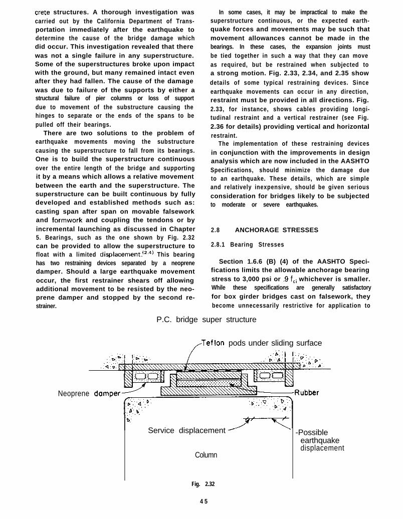
Crete structures. A thorough investigation wascarried out by the California Department of Trans-portation immediately after the earthquake todetermine the cause of the bridge damage whichdid occur. This investigation revealed that therewas not a single failure in any superstructure.Some of the superstructures broke upon impactwith the ground, but many remained intact evenafter they had fallen. The cause of the damagewas due to failure of the supports by either astructural failure of pier columns or loss of supportdue to movement of the substructure causing thehinges to separate or the ends of the spans to bepulled off their bearings.
There are two solutions to the problem ofearthquake movements moving the substructurecausing the superstructure to fall from its bearings.One is to build the superstructure continuousover the entire length of the bridge and supportingit by a means which allows a relative movementbetween the earth and the superstructure. Thesuperstructure can be built continuous by fullydeveloped and established methods such as:casting span after span on movable falseworkand formwork and coupling the tendons or byincremental launching as discussed in Chapter5. Bearings, such as the one shown by Fig. 2.32can be provided to allow the superstructure tofloat with a limited displacement.‘2.4’ This bearinghas two restraining devices separated by a neoprenedamper. Should a large earthquake movementoccur, the first restrainer shears off allowingadditional movement to be resisted by the neo-prene damper and stopped by the second re-strainer.
In some cases, it may be impractical to make thesuperstructure continuous, or the expected earth-quake forces and movements may be such thatmovement allowances cannot be made in thebearings. In these cases, the expansion joints mustbe tied together in such a way that they can moveas required, but be restrained when subjected toa strong motion. Fig. 2.33, 2.34, and 2.35 showdetails of some typical restraining devices. Sinceearthquake movements can occur in any direction,restraint must be provided in all directions. Fig.2.33, for instance, shows cables providing longi-tudinal restraint and a vertical restrainer (see Fig.2.36 for details) providing vertical and horizontalrestraint.
The implementation of these restraining devicesin conjunction with the improvements in designanalysis which are now included in the AASHTOSpecifications, should minimize the damage dueto an earthquake. These details, which are simpleand relatively inexpensive, should be given seriousconsideration for bridges likely to be subjectedto moderate or severe earthquakes.
2.8 ANCHORAGE STRESSES
2.8.1 Bearing Stresses
Section 1.6.6 (B) (4) of the AASHTO Speci-fications limits the allowable anchorage bearingstress to 3,000 psi or .9 fci whichever is smaller.While these specifications are generally satisfactoryfor box girder bridges cast on falsework, theybecome unnecessarily restrictive for application to
P.C. bridge super structure
/Teflon pods under sliding surface
Neoprene
b...
Service displacement
Column
Fig. 2.32
4 5
-Possibleearthquakedisplacement

_-----_--___ _----...
f/
/Vertical restrainer
Fig. 2.33 - Longitudinal and Vertical Restraints to Prevent Excessive Movements at the Hinge
\
6” galv pipe
3
#3 spiral 3” pitch------ 7-3/4”cables7-3/4”cablesSteel fLSteel fLPolystyrenePolystyreneElastomeric padElastomeric padSteel IiLSteel IiL
L Neoprene
Fig. 2.34
r
rFig. 2.35
46

3’-0” min
ELEVATION SECT ION
Fig. 2.36
the more sophisticated bridge types discussed inChapter 5. A more rational approach, for generaluse, is to determine the allowable anchorage bear-ing stress by the following equations:
At service load -f CP = 0.6 f;dmb
but not greater than 1.25 f:
At transfer load -f CP = 0.8 f:iJ&/A, - 0.2
but not greater than 1.25 f~i
wheref CP = permissible compressive concrete
s t r e s s
c = compressive strength of concretef~i = compressive strength of concrete at
time of initial prestress
Ab = maximum area of the portion of theconcrete anchorage surface that is geo-metrically similar to and concentricwith the area of the anchorage
Ab = bearing area of the anchorage
As used in the above equations, f,, is the averagebearing stress, P/A, in the concrete- computed bydividing the force P of the prestressing steel by thenet projected area, A,,, between the concrete andthe bearing plate or other structural element ofthe anchorage which has the function of trans-ferring the force to the concrete.
These equations have been verified by tests,the results of which have been reported in Refer-ence 2.5. These tests were designed to demonstratethat as the surrounding concrete area increased,the actual bearing stress under the plate could
exceed the 28-day compressive stress. The ringof surrounding concrete forms a container re-straining the rupturing action of the concretebeneath the anchor plate. The tests were runusing 8” diameter cylinders, 16’ long, with roundbearing plates 3”, 4”, 5”, 6”, 7”, and 8” in diame-ter which were centered on the ends of the cylinders.The ultimate unit bearing stresses under theplates varied almost exactly in reverse ratio to thediameter of the plates.
Later, another series of tests were run to deter-mine the constancy of the A,/Ab ratio for thefollowing parameters:
1. Concrete age ranging from 1 to 28 days.2. Varying size and shapes of bearing plates.3. Plates oriented other than 90” in relation to
the tendon axis.4. Concrete strengths ranging from 2,000 psi
to 6,000 psi.
The results indicate that:
1. The design computation can be logicallybased on the square root formula.
2. That tilting of the bearing plate up to 5”with respect to the tendon axis does notaffect the bearing ability.
3 . That these conclusions are valid for concretestrengths up to 6,000 psi. No tests weremade above 6,000 psi.
4 . That results are applicable in concretes from3 days of age upward.
5. That results are applicable to lightweightaggregate concretes as well as hard rockconcrete (for bearing only).
The bearing stress equations presented above yieldresults which recognize the geometrical relationbetween the anchorage plate and the concrete, andthese equations have been found to provide satis-factory results in practice. In some cases, the allow-able bearing stresses may be lower than the 3,000psi currently specified by AASHTO. This mayoccur, for example, when anchors are located inthin webs utilizing 3,500 psi or 4,000 psi concrete.For higher strength concretes, or for members withrelatively large concrete area compared to the sizeof the anchor, the allowable stresses will generallybe larger than 3,000 psi.
2.8.2 Bursting Stresses
Anchorage plates apply the prestress force ina fairly concentrated manner which involves highlocal stresses requiring a certain length to spreadout over the cross-section of the member. The
4 7

0. 3%t?
0.2%
1/8d 1/4d 3/8d 1/2d 5/8d 3/4d 7/8d d
length required for these localized stresses to dis-tribute is generally called the transmission zone.Depending on the size and location of the anchor-ages relative to the concrete section, significanttensile stresses can be generated in a directionperpendicular to the tendon in the transmissionzone.
If the anchorages are located in a massive sec-tion of concrete such as an end diaphragm or alarge end block, the tensile stresses can dissapatewithout causing distress to the concrete. A typicaldetail is shown in Fig. 3.2. On the other hand, ifthe anchorages are located in thin sections ofconcrete, reinforcement is usually required tocarry the tensile stresses and prevent the concretefrom splitting.
Leonhardt discusses the distribution and calcu-lation of the tensile bursting stresses in his text-book.‘2e’ Fig. 2.37, taken from Leonhardt’s text,shows the distribution of the tensile stresses in adirection parallel to the tendon path. These dis-tribution curves were plotted assuming the widthof the bearing plate equal to the width of theconcrete section. Therefore, they closely approxi-mate the stress distribution of anchorages on thinwalled members. The stresses imposed by theanchorage immediately behind the plate arecompressive but become tensile at some distanceaway from the plate depending on the ratio of thedepth of the anchor plate (a) to the depth of theconcrete section (d). Since only tensile forces areof concern in this context, only that portion of thediagram is shown by Fig. 2.37.
The magnitude of the tensile splitting force canbe determined from the following equation’2.6’:
X
Fig. 2.37
Z = 0.3 P(l-a/d)
Where:Z = total splitting or bursting forceP = tendon forcea = depth of the anchor plated = depth of the concrete section
Sufficient vertical reinforcement acting as a unitstress of 20,000 psi to resist the computed valueof Z should be distributed within the distance ofd/2 of the anchorage location. Normal shear rein-forcement may be included in the total area re-quired.
2.1
2.2
2.3
2.4
2.5
2.6
References
AASHTO, “Standard Speci f icat ions for HighwayBridges,” Eleventh Edition including Interims, TheAmerica1 Association of State Highway and Trans-portation Officials, Washington, D.C. 1975.Ghali, A., Dilger, W., and Neville. Adam M., “Time-Dependent Forces Induced by Settlement of Supportsin Continuous Reinforced Concrete Beams,” TitleNo. 66-78, ACI Journal/November, 1969, AmericanConcrete Institute, 1969.Elliott, Arthur L., “Hindsight and Foresight On ThePrestressed Concrete Bridges In The San FernandoEarthquake,” PCI Journal, Vol. 17, No. 2, March/April 1972, Prestressed Concrete Institute, Chicago,1972.Leonhardt, F., “Improving The Seismic Safety ofPrestressed Concrete Bridges,” PCI Journal, Vol. 17,No. 6, November/December 1972, Prestressed Con-crete Institute, Chicago, 1972.Middendorf, K. H., “Practical Aspects of End ZoneBearing of Post-Tensioning Tendons,” PCI Journal,Vol. 8, No. 4, August 1963, Prestressed ConcreteInstitute, Chicago, 1963.Leonhardt, F., “Prestressed Concrete-Design and Con-struction,” Second Edition, Wilhelm, Ernest & Sohn,Berlin, Munich, 1964.
48

CHAPTER 3
CONSTRUCTION ON FALSEWORK
3.1 CONSTRUCTION PLANS
Construction plans for conventional post-tensioned box girder bridges include two differentsets of drawings. The first set of drawings is pre-pared by the design engineer to outline the generaldesign requirements for the structure as part of thecontract documents. The second set of drawingsis the fabrication or shop drawings prepared by thepost-tensioning materials fabricator to supplyspecific details for installation of the post-tension-ing materials in compliance with the requirementsof the contract drawings. The contents of thesetwo sets of plans and their relationship as far asfabrication and installation of the post-tensioningmaterials is concerned is discussed in the followingsections.
3.1.1 Contract Plans
The contract plans should be prepared in such amanner that any post-tensioning system providingthe computed prestress requirement, can be in-stalled in the structure. A particular post-tension-ing system should not be detailed on these plansbut rather the prestressing requirements in termsof a moment envelope (force times eccentricity)should be detailed. The concrete sections shouldbe detailed so that any of the commercially availa-ble systems can be installed. This is accomplishedby following the design procedure outlined inChapter 2.
The designer should keep in mind that the post-tensioning system will not be installed from theinformation provided on the contract plans andthat the details of the post-tensioning system to beused will be supplied on the fabrication plans. Thecontract plans should contain the necessary infor-mation to allow the engineer to check whether thepost-tensioning system detailed on the fabricationplans satisfies the contract requirements. Thisinformation can most easily be presented by de-tailing an effective Pe (post-tensioning force afterlosses times eccentricity) diagram for the entirelength of the structure. An example of this diagramis shown by the longitudinal section in Fig. 3.1.Detailing only the center of gravity of steel andlocating it at the high low and inflection pointseffectively defines the required eccentricity for thespecified prestress at each point along the struc-
ture. This allows the post-tensioning materialsfabricator to vary the force or eccentricity or bothso that the maximum efficiency can be gainedfrom his system. The post-tensioning materialsfabricator has to meet the Pe requirements, whichwill result in the service load stresses calculated bythe designer and thus meet the contract require-ments.
Fig. 3.2 shows some typical details for post-tensioned box girder bridges cast on falsework. Theweb reinforcement adjustment detail should appearon the contract plans to indicate to the post-tensioning materials supplier an allowable solutionshould a conflict between a duct and a reinforcingbar occur. If such a conflict is likely to occur,this detail should also appear on the fabricationplans for the proper duct placement. The mini-mum laps should be dimensioned in accordancewith Article 1.5.22 of the AASHTO Specifica-tions.‘3.’ )’ Some typical anchorage bearing seatdetails showing typical anchorage reinforcementdetails are also shown in Fig. 3.2. A discussion ofanchorage reinforcement is included in Section 2.8.
3.1.2 Fabrication Plans
The fabrication plans are used to install andstress the post-tensipning system in the fieldfollowing review and approval by the engineer.Therefore, these plans must contain sufficientinformation to allow the engineer to check theircompliance with the contract plans, and mustpresent the installation and stressing procedures.
Details of the tendons must be shown, includinghorizontal and vertical dimensions at appropriateintervals so that the exact location and eccen-tricity can be easily determined. Fig. 3.3 shows anexample of these dimensions. Providing dimen-sions to the top or bottom of the conduits aswell as to the center-of-gravity of steel (cgs)facilitates the proper location of the conduitsby the workmen and helps to eliminate mistakes.
The type of anchorages and their locationsshould be shown, along with details of the anchor-ages. Fig. 3.3 shows typical details for locating theanchorages, and Fig. 3.4 indicates the requirementsfor detailing the anchorages. This information willbe used primarily by the contractor during theforming process rather than for verification ofcontract compliance.
*Superscripts refer to references listed at the end of the Chapter.
49

Note:At the contractor’s option the prestressing force may Path of center of gravityvary flO% from the theo. force per girder provided the of prestressing force is atotal force is obtained and is distributed sym. about series of second degreethe c of the typical section. parabolas between points
g bent-2 shown.Ordinates shownare ver t dimensions.
cabut -3
ii” typ.T
I I@I8 4 @I8 *4-w #5U stirrups
5@12 6@12 3@12LONGITUDINAL SECTION
TYPICAL Pfe DIAGRAM
Values shown are at Ho span or face of pier cap. Values shown are min. Pfxe at points shown. Unitsft.-kips. Pf=final prestress force after all losses. e= distance from cg of prestress force
Fig. 3.1 - Longitudinal Section Detail Showing Post-Tensioning Requirements

L Typ. extensionnn
I u I
ELEVATIONADJUSTMENT OF WEB REINF.
CONFLICTING WITH DUCTS
Gri I laqe #4@4 both ways
Girder
7YYlZEI-~.iiiII . / / ll
Center line r’
-&f
\Abut. reinf. continuous
girder thru anchorage.
20% & UNDER-PLAN ‘& 0
I’-0” embedment from line of backwallGrillage #4@4 both ways
pt4-total 4
20% G OVER-PLANBEARING SEAT FOR PRESTRESSED ANCHORAGE
AT DIAPHRAM TYPE ABUTMENT
Fig. 3.2 - Typical Reinforcement Details
‘r$ abut.
51

C G S1
CEcvTEAdNE
CEN7EPL/NE CENTE/ZL/NEG IROER GIRD&R
RDR /NG -- IF’LA7.E TV/>. AE~LzhuG
,/’ PLA 7E TV0
iA L VAN/.?,??0mx7 nJP/C
CGSf
ZPAAJ
7YP/CAL A~/T/--T-&NT DETAIL__--
IG /PDER J-EC ~/ON
Fig. 3.3 - Typical Fabrication Plan Details

This space normally reserved for:1. Tendon hardware details2. Jack clearance details3. Patterns for drilling forms for bearing
plates and attachment bolts.
NOTES1. Details shown are for placement tensioning and grouting of
prestressing materials only.
2. Prestressing tendons are composed of K inch 270 k.s.i.strands conforming to ASTM A-416.
3. Tendons are placed in rigid metal duct after bridge concreteplacement is completed.
4. Duct shall be placed to the trajectory shown on the drawings.
5. Duct shall be securely tied at 5 ft. plus centers to the verticalstirrups to prevent displacement during concreting.
6. Bearing plates must be placed tight against forms. Centerlineof tendons are to be normal to plates. Forms shall be bracedand anchored to support the weight of the bearing plates.
7. Reinforcing steel shall be adjusted or relocated during theinstallation of prestressing ducts, as required, to provideplanned clearances to the prestressing tendons, anchorages,jacks, and equipment.
8. Stressing sequence shall be as follows:
Stress no more than % of the tendons in one girder beforean equal number are stressed in adjacent girders.
At no time during stressing operations will more than 1/6thof the total prestressing force be eccentric about thecenterline of the bridge.
For single span structures tendons may be stressed fromone end only. With half of the tendons stressed from eache n d .
For continuous structures tendons will be stressed to Pifrom both ends. The two ends need not be stressed simul-taneously.
9. No welding shall be performed in the vicinity of high tensilesteel and sheathing.
10. During stressing no persons shall be directly behind eitherend of tendons.
11. All work shall conform to standard specifications and specialcondit ions.
These details are peculiar to the individual post-tensioningsystem being used.
I I I I I I I
Fig. 3.4 - Anchorage Detail Requirements and General Notes

The fabrication plans also contain the stressingdata. Fig. 3.3 and 3.4 show a tendon stressingschedule and a tendon data schedule respectively.The tendon stressing schedule or stressing sequenceis usually developed from guidelines set forth inthe contract plans or contract specifications. Thetendon data schedule is developed by the post-tensioning materials supplier using the anchor setof his particular system along with long termlosses and friction losses to meet the prestressingrequirements of the contract. The elongationcolumn can be set up in terms of maximum andminimum elongations which reflect the specifiedtolerance between the elongation and pressurereadings. This eliminates the need for the inspec-tor to compute the allowable elongation variationin the field.
Fig. 3.5 shows the clearance requirements fordifferent duct diameters. This figure also indicateshow multiple tendons should be arranged to facili-tate consolidation of the concrete around thetendon.
3.1.3 Other Details
Fig. 3.6 shows reinforced neoprene bearingdetails’3.2’ which may be used for post-tensionedbox girders cast on falsework. Types II and I I Iare predominately applicable for this type ofconstruction. Type I is suitable only on shorterspan lengths. Figs. 3.7 and 3.8 are design aids fordetermining the type and size of bearings applica-ble for various loading combinations and expansionlengths.
The Type I I assembly has a teflon sliding surfaceincorporated to provide movement capacity inaddition to that provided by the reinforced pad.The neoprene pad is bonded to the bottom plate.The movement is accomplished by both deforma-tion of the elastomer and slippage on the teflonsurface. The elastomer deforms until the internalshear force equals the friction force required toslip the teflon surface. The expansion lengthlimitations of the Type II assembly is 150 ft. fora 6 in. wide bearing and 300 ft. for the 12 in.wide bearing.
The Type III bearing will accommodate expan-sion lengths which exceed the limitations of theType II bearing. The Type I I I is essentially a
Type II with a restrictor pin added to prevent theelastomer from over-stressing in shear as movementoccurs. The movement in excess of that allowed bythe restrictor pin is accommodated by slippage onthe teflon surface. There are no limitations on theexpansion length for which the Type II I may beused as long as sufficient travel capability is pro-vided by the restrictor pin and the size of thestainless steel plate. The rubber thickness is basedon the deformation allowed by the restrictor pinand the rotational requirements for nonparallelload surfaces.
This type of bearing will accommodate theshortening dus to epplication of the post-tension-ing by presetting the teflon plates to make allow-ance for the expected shortening. The movementwhich occurs during the post-tensioning operationwill deform the rubber and maybe slide the stain-less steel plate depending on the magnitude of themovement. However, additional movement due totemperature effects will cause the bearing to re-adjust itself to a normal setting.
Fig. 3.9 shows another neoprene bearing con-figuration which will accommodate the movementoccurring as the post-tensioning force is applied.This bearing arrangement consists of a greasedneoprene bearing pad, either reinforced or unrein-forced, and a piece of 16 ga. sheet metal whichslides on the pad as shortening takes place. Fig. 3.9also shows the method for sizing the sheet metal.
Expansion joint sealers can be accommodatedby providing block-outs in the top slab as shownby Fig. 3.10. The anchorages of the tendons arenormally located symmetrically about the centerof gravity of the section, so they do not interferewith the cast-in-place bolts. However, if this por-tion of the slab is cast prior to the post-tensioningoperation, the location of the cast-in-place boltsmust recognize the shortening due to the post-tensioning force.
Fig. 3.11 shows a bolster hinge arrangementwhich eliminates the necessity for heavy false-work bents at hinge points. The two parts of thebolster hinge which are poured with the spans donot extend across the full width of the super-structure but are broken by stressing galleries. Thestressing galleries permit the casting of the bolsterhinge prior to stressing the post-tensioning tendonswhich allows the stressing loads to be carried bythe structure rather than falsework. After thestressing operation has been completed, the topslab is completed with a closure pour.
54

CLEARANCE REQUIREMENT FOR DUCTS
Shown for a 12” girder stem. Same minimumclearances apply to other stem widths.
.u -.-E=1T
3” min. cl. (except V/2”
min. near anchorage)
DUCTS 3” O.D. AND LESS
3” min. cl. (except V/2” -
min. near anchorage)
-
.0Ii.-E
i
7
DUCTS OVER 3” O.D.TO 4 l/2” O.D.
I I
DUCTS OVER 4 l/2” O.D.Fig. 3.5 - Duct Arrangement and Clearance Requirements
55

E l a s t o m e r i c -
TYPE I BEARING
Stainless steelsliding surface\
E l a s t o m e r i c 1bearing
e----w-------v
w--m----v-----
TYPE II BE ARING
Stainless steel
TYPE XI BEARING
ELASTOMERIC AND TFE ELASTOMERIC EXPANSION BEARINGSFig. 3.6
56

TLimits of typeIU TLimits of tvae I & II
. . . . . . . . . . . . . . . . . . . . . . . . . . . . .~.~.~.-,-.-.-.-.-.-.-.~. ::::. . . .,.._.............................
.~.‘.‘,‘.‘.~.‘.‘.‘.‘.‘.‘.‘.‘.~.~.~.-.-,‘.‘.‘.‘.‘.‘.‘.‘.‘.‘.‘.~.’.~_‘.‘.‘.‘.~.~.~.‘.‘.‘.‘.‘.‘.~.’ I
~.~.~,~.~.~.‘.‘.‘.‘.‘.‘,‘.‘.~.‘.’.’.’.’.’.’.~.~.‘.‘.‘.~riii:,::.:.:.,.,.,.:.:.:.:.:.:.:.:.:.:.:.:.:.:.:.:.:.:.:..::::::. ..~,~.~.~.~.~.~.~.~.~.~.~.~.~.~.~.~, , , x , 6
6 I I I I I I I I I I I I I I I I I I I I
0 50 100 150 200
Dead load + live load, in kips
PLAN DIMENSIONSVS LOADING
Fig. 3.7

5 12 x 18vC.-
.g I I x l 6m
E
-g IO x I4
ii
z 9 x 1 2E0.-
2 7 x 1 2
E.-
T 6 x 1 02a
Extension length, in feet
TYPE OF BEARINGVS EXPANSION LENGTH
Fig. 3.8
Extend sheet metal beyondpad a sufficient distanceto provide for shortening+I/2 temperature movement.
-16 go. galv. sheet metal.Coat top of pad with grease.
Fig. 3.9 - Greased Neoprene Bearing
5 8

expansion jt. (2”) l/4”
4
n Sealant
,11/2” bit. surf.
x Anchor boltscast in place
ne expansion jt. (2’/2’) V4”
Neoprene expansion jt. (4”)
a *31/2”< # a
eoprene expansion jt. (6V2”)
*At right angles at 50 OF
TYPICAL NEOPRENE EXP. JTS.AT POURED CONC. DECKS
Fig. 3.10
59

S U S P E N D E D E N D
SUPPORTING END
Fig. 3.11 - Typical Hinge Details
3.2 SYSTEMS INSTALLATION
The ease of installation of post-tensioning systemsis a major factor in the increasing acceptance ofpost-tensioned concrete box girder bridges.
The steps pictorially presented below represent theinstallation sequence for a cast-in-place prestressedpost-tensioned box girder bridge.
The installation begins with the placing of assem-blies consisting of bearing plate, transition coneor trumpet and grout inlet.

Duct sections are assembled with couplers insideor outside the structure at the contractor’s discre-tion and tied to the stirrups. Duct is normallydelivered in 20-30-40 foot lengths.

Anchorages and bearing plates are securely fastenedto the forms to prevent leakage of cement pasteand movement during concreting. Connectionsbetween trumpets and ducts, ducts and couplers,and ducts and vent saddles are taped to preventintrusion of mortar. The tape used is durable andwaterproof.

Two common methods for attaching “high point”grout vents on continuous tendons are shown.Above - brazed on type, below - saddle venttype. Rigid plastic pipe may be used in lieu of thesteel pipe shown in the above photograph. Therequired locations are contained in the groutingspecifications presented in Section 3.4.

At the completion of the duct installation and priorto placement of concrete in the top deck, a deviceof a slightly smaller diameter than I.D. of duct isblown or pulled through the duct to assure noundetected damage or blockage has occurred.

The strand is delivered to the site in sealed reel-less packs or reels containing desiccant to preventcorrosion. Strands are pulled from packs andassembled in groups as required for an individualtendon. A grip is placed over the end of the tendonand attached to a strand pulling cable. A powerdriven winch draws the tendon through the duct.Alternate methods of strand installation areavailable.

Stressing jack is moved to the stressing location byjack handling equipment. The strands of the tendonare threaded through and are held with wedgesduring the stressing operation. The handling equip-ment supports the jack during the entire operation.

Stressing equipment is removed and excess strandis cut to within approximately two inches of theanchorage. The excess strand should be cut onlyafter the tendon has received final approval.

Grout retaining caps are fitted and all tendons aregrouted using a cement and water grout mixturecontaining an approved additive. Specially designedmixers and grouting pumps are used for the groutingoperation.

At the completion of the grouting operation therecesses for the anchorages are cast solid withconcrete and the structure is ready for traffic.

3.3 STRESSING PROCEDURE
After all of the components of the post-tension-ing system are in place and the concrete hasreached the required strength, the tendons may bestressed. The stressing operation simply requiresplacing a large hydraulic jack on the tendonand stressing it to the required force. The totaltime involved in the stressing operation for amultistrand tendon is on the order of 15 to 30minutes depending on the number of strands inthe tendon and the weight of the related stressingequipment. The Engineer’s primary concern duringthe stressing operation is to assure that the jackforce specified on the approved fabrication planshas been applied to the tendon. The tendon forceis measured by both gage pressure and tendonelongation as described in Sections 3.3.1 and 3.3.2,respectively. The accuracy of the gage pressurereadings can be calibrated annually, or as required,by use of a load cell as outlined in Section 3.3.3.
Details of the center pull and shoulder pullhydraulic rams used by the post-tensioning indus-try are shown in Fig. 3.12. Load cells are shown inplace in Fig. 3.12 for illustrative purposes only.As noted above, the load cell is normally onlyused periodically to verify the jack calibration.
The tendons are stressed in a sequence specifiedon the approved fabrication plans. (See Sec. 3.1.2).The stressing sequence is developed to minimizethe eccentricity of the prestressing force about thecenterline of the bridge and to minimize differen-tial shortening of the concrete. The following aretwo rules which the stressing sequence shouldfollow:
1. Stress no more than % of the tendons inone girder before an equal number arestressed in adjacent girders.
2. At no time during the stressing operationswill more than l/6 of the total prestressingforce be eccentric about the centerline ofthe bridge.
For economical reasons, always stress the ten-dons from one end (single end stressing) whereverpossible. Moving the jack from end to end of thebridge or providing a second jack is an additionalexpense which the post-tensioning materialssupplier passes on to the owner, but this expensecan sometimes be eliminated by some forethoughtand planning. Simple span structures can almostalways be stressed from one end. If a girder con-tains two tendons, it might be possible to stressone tendon from one end and the other tendon
from the other end. In multi-span continuousstructures, the fact that usually only one or twopoints govern the prestress requirements, and thatthe tendon stress diagrams can be superpositionedprovide useful tools for determining whetherstressing each tendon from both ends (double endstressing) is required.
Figs. 3.13 and 3.14 show the resultant tendonforce diagrams of stressing two tendons by singleend stressing from opposite ends (Fig. 3.13) andstressing two tendons by double end stressing(Fig. 3.14). These simplified resultant tendonforce diagrams show that the resultant force inthe middle half of the tendon length is almostidentical in either case. Therefore, if the criticalprestress requirement occurs in the middle halfof the tendon length, the most economical methodfor stressing the girder is to single end stress thetendons from opposite ends saving the time re-quired to attach the jack to each tendon a secondtime.
In some cases, however, double-end stressingof the tendons is required. For instance, if theprestress requirement at the quarter point ofthe tendon depicted by Fig. 3.13 and 3.14 islarger than 1.6 Pj, the tendons must be double-endstressed. Double-end stressing should be done withonly one jack and not stressed simultaneouslywith two jacks. In this instance, moving the jackfrom one end to the other is more economicalthan providing a second jack at the jobsite. Theonly difference in the resulting tendon force isthe point of zero tendon movement is a smalldistance from that of a tendon which is stressedPj at both ends at two different times. This dis-tance is so insignificant that the tendon forcediagrams are essentially identical.
3.3.1 Gage Pressure
A pressure gage is attached to the hydrauliclines running between the pump and the ram whichmeasures the hydraulic oil pressure. These readings,with the aid of a calibration chart, indicate themagnitude of the force that the ram is exerting.The calibration chart is developed by using a loadcell to measure the actual force exerted by the ramfor a particular gage reading. Pressure readingsversus force readings are plotted for incrementsof force ranging from about 10 percent to 120percent of the specified jack force. The resultingcalibration chart is a straight line from which theforce can be determined for any pressure gage
70

/
Jack chair/Anchor block
// I I - n n r k i n n
Center hole ram (piston)
BridgeFace
TYPICAL CENTER PULL POST -TENSIONING JACK
I/Anchor head
Bearing plate ~1: (female cone)
Threaded hole for detensioning
Front alignment\ ’
‘Mark elongation hereAdjusting threads
Note:- -- Absence of male cone
while calibrating
TYPICAL SHOULDER PULL POST-TENSIONING JACK
Fig. 3.12
71
lead

1.3Pj
1.6 Pj I .6 Pj 1.6 Pj
Tendon I+ tendon II:1.3 Pj
TWO TENDONS-SINGLE END TENSIONEDOPPOSITE ENDS
Fig. 3.13
pj
.7Pj
l.4.Pj
Tendon I or II
Tendon I+ tendon III
pj
.7Pj
l.4Pj
TWO TENDONS-DOUBLE END TENSIONED
Fig. 3.14
72
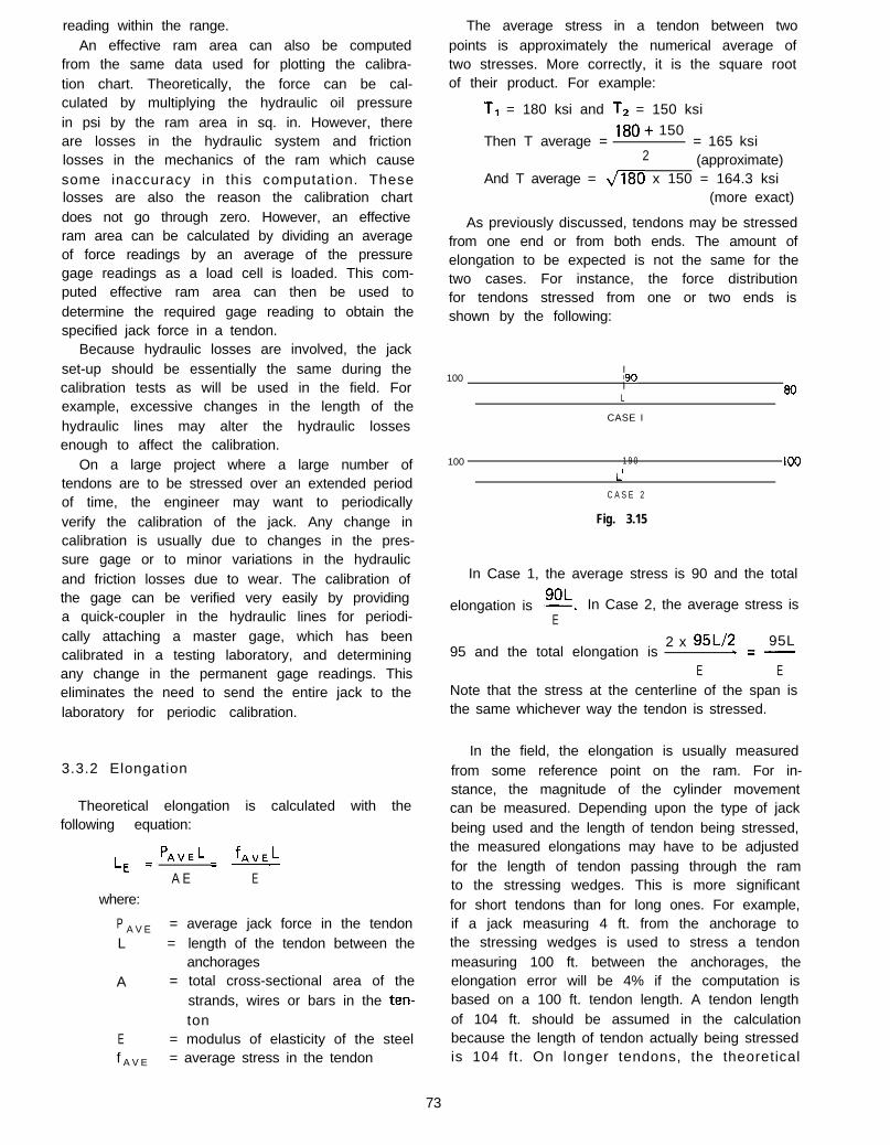
reading within the range.An effective ram area can also be computed
from the same data used for plotting the calibra-tion chart. Theoretically, the force can be cal-culated by multiplying the hydraulic oil pressurein psi by the ram area in sq. in. However, thereare losses in the hydraulic system and frictionlosses in the mechanics of the ram which causesome inaccuracy in this computation. Theselosses are also the reason the calibration chartdoes not go through zero. However, an effectiveram area can be calculated by dividing an averageof force readings by an average of the pressuregage readings as a load cell is loaded. This com-puted effective ram area can then be used todetermine the required gage reading to obtain thespecified jack force in a tendon.
Because hydraulic losses are involved, the jackset-up should be essentially the same during thecalibration tests as will be used in the field. Forexample, excessive changes in the length of thehydraulic lines may alter the hydraulic lossesenough to affect the calibration.
On a large project where a large number oftendons are to be stressed over an extended periodof time, the engineer may want to periodicallyverify the calibration of the jack. Any change incalibration is usually due to changes in the pres-sure gage or to minor variations in the hydraulicand friction losses due to wear. The calibration ofthe gage can be verified very easily by providinga quick-coupler in the hydraulic lines for periodi-cally attaching a master gage, which has beencalibrated in a testing laboratory, and determiningany change in the permanent gage readings. Thiseliminates the need to send the entire jack to thelaboratory for periodic calibration.
3.3.2 Elongation
Theoretical elongation is calculated with thefollowing equation:
’ L fAVELL, = A”E = --c
A E E
where:
P A V E = average jack force in the tendonL = length of the tendon between the
anchoragesA = total cross-sectional area of the
strands, wires or bars in the ten-ton
E = modulus of elasticity of the steelf A V E = average stress in the tendon
The average stress in a tendon between twopoints is approximately the numerical average oftwo stresses. More correctly, it is the square rootof their product. For example:
T, = 180 ksi and T, = 150 ksi
Then T average =180+ 150
= 165 ksi2 (approximate)
And T average = J180 x 150 = 164.3 ksi(more exact)
As previously discussed, tendons may be stressedfrom one end or from both ends. The amount ofelongation to be expected is not the same for thetwo cases. For instance, the force distributionfor tendons stressed from one or two ends isshown by the following:
I100 !90
I 00L
CASE I
100 1 9 0 loo
L’
C A S E 2
Fig. 3.15
In Case 1, the average stress is 90 and the total
9OLelongation is --. In Case 2, the average stress is
E
95 and the total elongation is2 x 95Ll2 95L
.=-
E ENote that the stress at the centerline of the span isthe same whichever way the tendon is stressed.
In the field, the elongation is usually measuredfrom some reference point on the ram. For in-stance, the magnitude of the cylinder movementcan be measured. Depending upon the type of jackbeing used and the length of tendon being stressed,the measured elongations may have to be adjustedfor the length of tendon passing through the ramto the stressing wedges. This is more significantfor short tendons than for long ones. For example,if a jack measuring 4 ft. from the anchorage tothe stressing wedges is used to stress a tendonmeasuring 100 ft. between the anchorages, theelongation error will be 4% if the computation isbased on a 100 ft. tendon length. A tendon lengthof 104 ft. should be assumed in the calculationbecause the length of tendon actually being stressedis 104 ft. On longer tendons, the theoretical
73

elongation may be larger than the travel lengthof the ram. In this instance the ram must berecycled and the summation of the elongationmeasurements compared to the theoretical elonga-tion. Precautions must be taken for determiningwhether or not the strands slip in the wedgesduring the stressing operation. Painting the strandsadjacent to the wedges prior to stressing willindicate whether any relative movement occursduring the stressing operation.
As was previously mentioned, both pressuregage readings and strand elongation measurementsare taken during the stressing operation to verifythe jack force. Generally these two measurementsshould agree within 5% to 7%. If the variance islarger, the stressing operation should be stoppeduntil the reason for the variation is determined.Disagreement in the two measurements could bedue to friction and wobble losses larger than thosewhich were calculated, the tendon being hung up,or one of the measurements being incorrect. Whenin doubt, always use the gage reading to measureforce in preference to elongation.
In actual construction, each tendon has a smallunmeasurable amount of slack. To eliminate theeffect of initial slackness in the tendon elongationmeasurements, the tendon is initially stressed to10% of the required force, and the elongation ismeasured from this point to the specified jackforce. This measured elongation is then comparedto 90% of the calculated theoretical elongation.
3.3.3 Load Cells
A third method for verifying the jack force inthe tendon is the use of either electric or hy-draulic load cells. The load cells are installedbetween the stressing wedges and the anchorageplates and indicate the jack force by measuringstrain.
When working properly, load cells can measurethe jack force very accurately. However, loadcells are expensive to build and maintain. Main-tenance becomes a particular problem in the dirtand grime of a field operation. They are alsoexpensive to use in the field because of the timerequired for installation as the ram is attachedto each tendon. A load cell is a scientific instru-ment and must be handled accordingly. An impactof any kind, or dirt can destroy the calibrationmaking the load cell useless until it has beenrecalibrated in a laboratory.
3.4 GROUTING
Grouting of the tendons serves two very impor-tant purposes. First, the grout provides bondbetween the prestressing steel and the concrete.Second, grouting provides corrosion protection forthe steel. It is of vital importance that the groutingoperation be conducted carefully in accordancewith the specifications presented in Section 3.4.1,or other applicable specifications.
Although the incidence of corrosion problemsin completed post-tensioned structures has beenexceedingly small, there have been a number ofcorrosion failures of individual tendons in cir-cumstances where, the grouting was not doneproperly, or was not done at all. These instancesemphasize the importance of adherence to goodgrouting procedures.
A number of studies have been made to evaluateboth the adequacy of grouting procedures inproviding complete grout encasement of thetendon material, and the protection provided bygrouting against corrosion in aggressive environ-ments.‘3.3’ (3.4) (3.5J National Cooperative HighwayResearch Program Report 90, “Protection ofSteel in Prestressed Concrete Bridges” publishedin 1970, includes the following statement in thereport summary:
“Examination of steel from fragments ofprestressed bridges and piles that had beenexposed in severe environments for extendedperiods showed virtually no corrosion or lossin properties of the steel. These observationscombined.with the many other findings ob-tained during the course of the study resultedin the conclusion that concrete when properlyused can provide satisfactory long-time cor-rosion protection for prestressing steel.”
In February 1977, the U.S. Army EngineerWaterways Experiment Station published Report4 in a series of reports on “Durability and Behaviorof Prestressed Concrete Beams.” The reportentitled “Post-Tensioned Concrete Beam Investi-gation with Laboratory Tests from June 1961 toSeptember 1 975”‘3.4’ deals with the durabilitybehavior of a series of post-tensioned prestressedconcrete beams. Twenty post-tensioned concretebeams were cast between 23 September 1960 and3 March 1961 and placed at half-tide elevation atthe Treat Island Maine, exposure station in June1961. The beams were subjected to twice dailytidal inundations plus freezing in air and thawingin sea water for 12 to 13 winters. The twentyair-entrained concrete beams were rectangular at
74

the ends (lo-by 16-in. cross section) and were96 in. long with a 68 in. long thin web section(5-by 6-in. cross section). Nineteen of the beamscontained grouted post-tensioning surrounded bya flexible metal conduit. The other beam con-tained one unbonded, greased post-tensioningtendon spiral-wrapped with paper. In 1973 and1974, eight of the beams were returned to theWaterways Experiment Station to evaluate theperformance of the prestressing steel and anchor-age systems subjected to adverse long-term weather-ing conditions. In addition to observation of thecondition of the beams, they were subjected tostructural testing to failure and to physical andchemical analysis. Of the eight beams, five weresubjected to 1737 cycles of freezing and thawingover a period of twelve winters, and three weresubjected to 1873 cycles of freezing and thawingover a period of thirteen winters. The tendons inthe test specimens consisted of 0.196 or 0.25 in.diameter 240 ksi wires, or 7/8 in. diameter 160ksi bars. On opening the beams following thestructural testing, each wire or bar of each beamwas found to be rusted to some degree. The reportpresents the following conclusion relative to struc-tural and physical tests:
“In the structural testing of all eight beams,only one wire broke during testing (a wirein the unbonded beam), and subsequent toopening the beams, only five pieces of wirewere found that did not conform to ASTMultimate stress requirements. Only 17 piecesof wire failed to meet ASTM requirements fortotal elongation under load and elongation at1 percent of load, and of these 17, eight werefrom the landward end of the unbonded beam.These failures to meet ASTM ultimate stressor total elongation requirements account foronly 22 out of 157 tests. It is therefore con-cluded that the steel wires or bars were notstructurally damaged by exposure to severeenvironments of freezing and thawing in asaline surrounding when the post-tensioningconduit was filled with a grout mixture toprotect the strands.”
Examination of the wires in the unbonded beamafter structural testing revealed “many areas ofthe wires were either not covered with grease, orwere covered with dried-out grease.” Even thoughthese areas of wire in the unbonded tendon wereheavily rusted, only one of 24 pieces of wiretested from the unbonded beam failed to developthe 240,000 psi ultimate stress and this specimenbroke at 239,222 psi. In summary, the TreatIsland Exposure tests are believed to reflect favor-
ably on the durability of post-tensioned elementsexposed to severe environments. Improvementsin grouting procedures since the Treat Island testspecimens were produced in 1960 should provideeven better protection than was evidenced in thesetests.
In 1971 and 1972, the California Department ofTransportation in cooperation with the FederalHighway Administration sponsored a study todetermine the quality of grout being obtained withcurrent grouting procedures.‘3.5’ Seven bridges,each on a separate construction contract wereselected as representative post-tensioned structuresand provisions were made to inspect the groutedtendons at low points, inflection points and athigh points. Some of the tendons were unventedto determine whether venting has a significanteffect on the quality of the grout, and in somecases no expansive admixture was used in the grout.The summary of the findings and conclusions fromthis studv is as follows:
“1. The quality of the grout as seen in the96 duct openings in a total of 24 tendons inseven bridges was generally very good. Thecurrent grout specifications and equipmentappear to produce a satisfactory product.
2. Water voids at the top surface are com-monly found at the tendon high points. Theydo not expose any tendon steel because thestrands are pulled to the bottom of the ductat these places.
3. The type of exposure caused by thestrand bearing against the helical duct seamprobably cannot be eliminated.
4. Omitting high point vents did notseem to have any visible effect on the qualityof the result.
5. Elimjnation of the expansive admixturehad no apparent effect on the quality of thegrout.”
During the time the cooperative study of groutquality was being conducted by the CaliforniaDepartment of Transportation, the San Fernandoearthquake of 1971 occurred, and a number ofpost-tensioned bridges failed due generally toinadequate connections and bearing details (seediscussion in Section 2.7). These bridges providedthe investigators an opportunity to salvage sec-tions of grouted tendons from three bridges forlaboratory evaluation in conjunction with the testsof the seven bridges described above. Laboratoryinspection of the tendon specimens from thesebridges resulted in the following observation:
75

“All three bridges had been built within afew months of the earthquake so no timerelated deterioration could be observed. Sincethese tendons were representative of normalconstruction practice, their overall excellentcondition was very reassuring.”
In summary, the results of various researchprojects and the limited incidence of corrosionproblems in post-tensioned bridges both suggestthat excellent corrosion protection is provided bythe use of proper grouting procedures. At thesame time, the limited number of problems andtendon failures which have occurred emphasizethe importance of the use of proper groutingtechniques to the long term durability of post-tensioned structures. Use of the grouting proce-dures presented in Section 3.4.1 in conjunctionwith care during construction to assure that thetendon duct is not damaged prior to grouting arestrongly recommended to assure that the highdurability potential of post-tensioned bridges isobtained in practice.
3.4.1 Recommended Practice For Grouting ofPost-Tensioned Prestressed Concrete
GUIDE SPECIFICATIONS
(A) General
(1) Scope and purpose.
(1 .l) These recommendations cover the groutingof post-tensioning tendons of prestressedconcrete members.
(1.2) The purpose of grouting is to providepermanent protection to the post-tension-ing steel and to develop bond between theprestressing steel and the surrounding con-crete.
(2) Definition of Terms. - All terms and sym-bols shall be defined in “Guide Specificationfor Post-Tensioning Materials,” - Post-Tensioning Institute.
(2.1) Admixture - Any material added to thegrout other than portland cement and water.
NOTES TO SPECI F IERS
These procedures also apply to grouting of rockand soil anchors. However, since the hardenedgrout in rock and soil anchor applications sustainsthe full post-tensioning force, more detailed con-sideration must be given to grout strength andinjection procedures.
76

GUIDE SPECIFICATIONS NOTES TO SPECIFIERS
(2.2) Duct - The hole or void provided in theconcrete for the post-tensioning tendon.
(2.3) Grout - A mixture of cement and waterwith or without admixtures.
Although sand has not been used in groutingpractices in the United States, it may have advan-tages in tendons with large void areas. Fly ash andpozzolans are occasionally used as filler material inthe United States.
(2.4) Grout Opening or Vent - An inlet, outlet,or vent in the duct for grout, water or air.
(2.5) Post-Tensioning - The method of pre-stressing concrete in which the tendon isstressed after the concrete has reached aspecified strength.
(2.6) Post-Tensioning Tendon - The completeassembly consisting of anchorage andprestressing steel with sheathing whenrequired. The tendon imparts prestressingforces to the concrete.
(2.7) Prestressing Steel - That element of a post-tensioning tendon which is elongated andanchored to provide the necessary perma-nent prestressing force.
(B)
(1)
(2)
(3)
Materials
Portland Cement - Portland cement should Normally, Type III cement is only used for coldconform to one of the following: Specifica- weather grouting. Trial mixes are necessary totions for portland cement - ASTM C150, determine an appropriate mix design using Type I I IType I, II or Ill. cement.
Cement used for grouting should be freshand should not contain any lumps or otherindication of hydration or “pack set.”
Water - The water used in the grout shouldbe potable, clean and free of injurious quan-tities of substances known to be harmful toportland cement, or prestressing steel.
Known harmful substances are chlorides, florides,sulphites and nitrates.
Admixtures - Admixtures, if used, shouldimpart the properties of low water content,good flowability, minimum bleed and expan-sion if desired. Its formulation should con-tain no chemicals in quantities that mayhave harmful effect on the prestressingsteel or cement. Admixtures containingchlorides (as Cl in excess of 0.5% by weightof admixture, assuming 1 pound of admix-
Admixtures commonly used to provide expansionof the grout may also reduce the water require-ment, or improve flowability at a given watercontent, and retard set. Such admixtures arenormally used. However, research for basicallyhorizontal tendons in rigid ducts suggests thatsatisfactory grout quality may be achieved withoutadmixtures.
77

- (a) Formed Ducts - Ductsformed by sheath left in place should beof a type that would not permit the en-trance of cement paste. They should transferbond stresses as required and should retainshape under the weight of the concrete.Metallic sheaths should be of a ferrous metal,and they may be galvanized.
(b) Cored Ducts - Cored ducts should beformed with no constrictions which wouldtend to block the passage of grout. Allcoring material should be removed.
(2) Grout Openings of Vents - All ducts shouldhave grout openings at both ends. Fordraped cables over 400 ft. in length, allhigh points should have a grout vent exceptwhere cable curvature is small, such as incontinuous slabs. Grout vents or drain holesshould be provided at low points if thetendon is to be placed, stressed and groutedin a freezing climate. All grout openings orvents should include provisions for pre-venting grout leakage.
(3) Duct Size - For tendons made up of aplurality of wires, bars, or strands, ductarea should be at least twice the net area ofthe prestressing steel.
For tendons made up of a single wire, baror strand, the duct diameter should be atleast ‘/o inch larger than the nominal diam-eter of the wire, bar or strand.
Current international standards suggest thatbleeding may be measured in a metal or glasscylinder with an internal diameter of approxi-mately 4 inches, with a height of grout of approxi-mately 4 inches. However, recent research in theUnited States indicates that more representativetests results may be achieved using a grout speci-men of approximately 20 inch height and 1%inch diameter. During the test, the containershould be covered to prevent evaporation. It issuggested that the following approximate limitson bleeding be used to evaluate the acceptabilityof the grout: 2% of the volume 3 hours aftermixing; a maximu’m of 4%. In addition, the sepa-rated water should be absorbed after 24 hours.
Materials commonly used for formed ducts are22 to 28 gauge galvanized or bright spirally woundor longitudinally seamed steel strip with flexibleor semi-rigid seams.
Material used for grout vents or drain holes maybe either plastic or ferrous metal.
Grout vent details for rock and soil anchors requirespecial considerations particular to the application.
78
! I
GUIDE SPECIFICATIONS NOTES TO SPECIFIERS
ture per sack of cement), florides, sulphitesand nitrates should not be used.
Aluminum powder of the proper finenessand quantity or other approved gas evolvingmaterial which is well dispersed throughthe other admixture may be used to obtain5% to 10% unrestrained expansion of thegrout. All admixtures should be used inaccordance with the instructions of themanufacturer.
(C ) Ducts
( 1 ) F o r m i n g

(4)
(D)
(1)
(2)
(3)
(4)
(5)
GUIDE SPECIFICATIONS
Placement of Ducts - After placing ofducts, reinforcement and forming is com-plete, an inspection should be made tolocate possible duct damage. Ducts shouldbe securely fastened at close enough inter-vals to avoid displacement during concreting.
All holes or openings in the duct must berepaired prior to concrete placing.
Grout openings and vents must be securelyanchored to the duct and to either the formsor to reinforcing steel to prevent displace-ment during concrete placing operations.
Equipment
The grouting equipment should include amixture capable of continuous mechanicalmixing which will produce a grout free oflumps and undispersed cement. The equip-ment should be able to pump the mixedgrout in a manner which will comply withall provisions of this recommended practice.
Accessory equipment which will providefor accurate solid and liquid measuresshould be provided to batch all materials.
The pump should be a positive displacementtype and be able to produce an outletpressure of at least 150 psig. The pumpshould have seals adequate to prevent intro-duction of oil, air or other foreign substanceinto the grout, and to prevent loss of groutor water.
A pressure gage having a full scale reading ofno greater than 300 psi should be placed atsome point in the grout line between thepump outlet and the duct inlet.
The grouting equipment should contain ascreen having clear openings of 0.125 inchmaximum size to screen the grout prior toits introduction into the grout pump. Ifa grout with a thixotropic additive is used,a screen opening of 3/16 inch is satisfactory.This screen should be easily accessible forinspection and cleaning.
NOTES TO SPECIFIERS 1
There are two methods of placing tendons. First,preassembled tendons may be placed as a unitprior to placing concrete. Second, bearing platesand duct sheathing may be installed prior to plac-ing the concrete, and then after concreting, theprestressing steel and anchorages are installed.Ties for pre-placed tendons must be adequate tosupport the tendon weight. When only the ductis placed prior to concreting, ties must resistbouyancy forces.
It is suggested that standby water flushing equip-ment should be available where difficult groutingconditions exist. This equipment should be inaddition to the grouting equipment. The standbywater flushing equipment should utilize a differentpower source than the grouting equipment, havesufficient capacity to flush out any partiallygrouted enclosures if necessary due to blockage orbreakdown of grouting equipment, and shouldbe capable of developing a pressure of at least300 psig.
A thixotropic groutin fluidity dependingmotion or quiescent.by additives.
undergoes marked changeson whether the grout is inThis property is produced
79

6)
(7)
(El
(1)
(2)
(3)
(4)
GUIDE SPECIFICATIONS NOTES TO SPECIFIERS
The grouting equipment should utilizegravity feed to the pump inlet from ahopper attached to and directly over it.The hopper must be kept at least partiallyfull of grout at all times during the pump-ing operation to prevent air from beingdrawn into the post-tensioning duct.
Under normal conditions, the groutingequipment should be capable of continu-ously grouting the largest tendon on theproject in no more than 20 minutes.
Mixing of the Grout
Water should be added to the mixer first,followed by portland cement and admixture,or as required by the admixture manufac-turer.
Mixing should be of such duration as toobtain a uniform thoroughly blended grout,without excessive temperature increase orlossof expansive properties of the admixture.The grout should be continuously agitateduntil it is pumped.
Equipment currently in use normally requires 1%to 3 minutes to satisfactorily mix the grout.
Water should not be added to increase groutflowability which has been decreased bydelayed use of the grout.
Proportions of materials should be based ontests made on the grout before grouting isbegun, or may be selected based on priordocumented experience with similar materialsand equipment and under comparable fieldconditions (weather, temperature, etc.) Thewater content shall be the minimum neces-sary for proper placement, and when Type Ior II cement is used should not exceed awater-cement ratio of 0.45 (approximately5 gallons of water per sack of cement).
Hardened grout made in accordance with thisspecification at a temperature of 65 degrees F. anda relative humidity of approximately 70% willproduce 28 day compressive strengths of about4,000 psi when cured under confined conditions.
The water content required for Type I IIcement should be established for a particularbrand based on tests.
The pumpability of the grout may bedetermined by the Engineer in accordancewith the U.S. Corps of Engineers MethodsCRD-C79. When this method, is used, theefflux time of the grout sample immediatelyafter the mixing should not be less than 11
80
GUIDE SPECIFICATIONS NOTES TO SPECIFIERS ’
seconds. The flow cone test does not applyto grout which incorporates a thixotropicadditive.
(F) Grout Injection
(1) Preparation of the duct.
(1 .l) Flushing of metal ducts should be optionalwith the post-tensioning contractor.
Historically, flushing has been used to clear theduct of foreign materials, and to wet the duct andtendon surfaces to improve the groutability. Whentendons are flushed, the water may be removed byoil-free air, or it may be displaced by the grout.In recent years, grouting experiences with rigidconduit and prestressing steel placed after concret-ing indicate that flushing is not necessary and maybe undesirable for large tendons since it is diffi-cult to remove the water from the duct.
(1.2) Ducts with concrete walls (cored ducts)should be flushed to ensure that the con-crete is thoroughly wetted.
(1.3) Water used for flushing ducts may containslack lime (calcium hydroxide) or quick-lime (calcium oxide) in the amount of 0.1pounds per gallon.
(2) Injection of the grout.
(2.1) All grout and high point vent openingsshould be open when grouting starts. Groutshould be allowed to flow from the firstvent after the inlet pipe until any residualflushing water or entrapped air has beenremoved, at which time the vent should becapped or otherwise closed. Remainingvents should be closed in sequence in thesame manner.
(2.2) The pumping pressure ‘at the tendon inletshould not exceed 250 psig.
When pumping grout, pressures in excess of 250psi result in separation of water and cement, whichmay cause a blockage. Excessive pressures couldalso result in cracking or damage to the structuralelement. It is therefore advisable to keep groutpumping pressures under this level. This can bedone by visually monitoring the pressure gage,or by equipment which includes automatic ormanual bypasses.
(2.3) If the actual grouting pressure exceeds themaximum recommended pumping pressure,grout may be injected at any vent which has
8 1

(2.4)
(2.5)
GUIDE SPECIFICATIONS NOTES TO SPECIFIERS
been, or is ready to be, capped as long asa one-way flow of grout is maintained. Ifthis procedure is used, then the vent whichis to be used for injection should be fittedwith a positive shut-off.
When one-way flow of grout cannot bemaintained as outlined in Sections (2.1) and(2.3) above, the grout should be immedi-ately flushed out of the duct with water.
Grout should be pumped through the ductand continuously wasted at the outlet pipeuntil no visible slugs of water or air areejected and the efflux time of the ejectedgrout should not be less than the injectedgrout. To insure that the tendon remainsfilled with grout, the outlet and/or inletshould be closed. Plugs, caps or valves thusrequired should not be removed or openeduntil the grout has set.
Current research indicates that use of standpipes athigh points of grouted tendons is a satisfactorysubstitute for a positive means of shut-off. Stand-pipes permit free expansion which tends to pushout any bleed water that may occur at high points.
Vertical or nearly vertical tendons made up ofstrands, which tend to act as filters for the grout,require special consideration. Because of exag-gerated bleed, special grouting techniques shouldbe used to ensure complete filling of the topportion of the tendon. This may be achieved bytwo stages of grouting, free expansion of groutpushing the bleed water out at the high points, oradmixtures which increase the water retentivityso that bleed is controlled.
(G) Temperature Considerations
(1) In temperatures below 32 degrees Fahren- This is normally accomplished with low pointheit, ducts should be kept free of water to drains.avoid damage due to freezing.
(2) Concrete temperature - The temperatureof the concrete should be 35” F. or higherfrom the time of grouting until job cured2 inch cubes of grout reach a minimumcompressive strength of 800 psi.
At 35 degrees F. grout may be expected to reachBOO psi cube strength in about 5 days.
(3) Grout temperature - Grout should not be Difficulties in pumping grout may occur whenabove 90” F. during mixing or pumping. If the grout temperature in the mixer exceeds 90necessary, the mixing water should be degrees F.cooled.
(H) Method of Test For Flow of Grout Mixtures(Flow-Cone Method)
CRD-C 79-58 (Issued Sept. 1, 1958)
8 2

Scope
1 . This method of test covers the procedure tobe used both in the laboratory and in thefield for determining the flow of grout mix-tures by measuring the time of efflux of aspecified volume of grout from a standardizedflow cone.
Apparatus
2 (a) Flow Cone. - The flow cone shallconform to the dimensions and other re-quirements indicated in Fig. 3.16.
3-1116” DIAMPOINT GAGE.TACK WELD
ALUMINUM
BOLT FLANGE
I.D
Cross section of flow cone
Fig. 3.16
(b) Stop Watch. - A stop watch having a leastreading of not more than 0.2 sec.
Calibration of Apparatus
3 . The flow cone shall be firmly mounted insuch a manner that the top will be level andthe cone free from vibration. The dischargetube shall be closed by placing the fingerover the lower end. A quantity of waterequal to 1725+ 1 ml shall be introduced intothe cone. The point gage shall be adjustedto indicate the level of the water surface.
Sample
4. The test sample shall consist of 1725? 1 mlof grout.
Procedure
5. Moisten the inside surface of the flow cone(Note). Place the finger over the outlet ofthe discharge tube. Introduce grout into thecone until the grout surface rises into con-tact with the point gage. Start the stopwatch and remove the finger simultaneously.Stop the stop watch at the first break in thecontinuous flow of grout from the dischargetube. The time indicated by the stop watchis the time of efflux of the grout. At leasttwo tests shall be made for any grout mix-ture.
Note: A recommended procedure for insuring thatthe interior of the cone is properly wettedis to fill the cone with water and, oneminute before beginning to add the groutsample, allow the water to drain from thecone.
Report
6. The report shall include:
(a) Average time of efflux to the nearest0.2 set,
(b) Temperature of the sample at the timeof test,
(c) Ambient temperature at the time of thetest,
(d) Composition of the sample, and(e) Information on the physical characteris-
tics of the sample.
8 3

3.5 TYPICAL STANDARD SPECIFICATIONSFOR POST-TENSIONED PRESTRESSEDCONCRETE
3.5.1 Description
This work shall consist of prestressing cast-in-place concrete by furnishing, placing, and tension-ing of prestressing steel in accordance with detailsshown on the plans, and as specified in thesespecifications.
This work shall includethe furnishing and install-ing of any appurtenant times necessary for theparticular prestressing system to be used, includingbut not limited to ducts, anchorage assemblies,prestressing steel and grout used for pressuregrouting ducts.
For cast-in-place prestressed concrete, the term“ m e m b e r ” as used in this specification shall beconsidered to mean the concrete which is to beprestressed.
3.5.2 Prestressing Methods
Prestressing shall be performed by post-tension-ing methods.
The Contractor shall submit to the Engineerfor review complete details of the method, ma-terials and equipment he proposes to use in theprestressing operations, including any additionsor rearrangement of reinforcing steel from thatshown on the plans. Such details shall outline themethod and sequence of stressing and shall includecomplete specifications and details of the prestress-ing steel and anchoring devices, working stresses,anchoring stresses, type of ducts, and all otherdata pertaining to the prestressing operation,including the proposed arrangement of the pre-stressing steel in the members, pressure groutingmaterials and equipment. The Contractor shall notcast any member to be prestressed before reviewand approval of the shop detail drawings is com-plete.
3.5.3 Prestressing Steel
Prestressing steel shall be stress-relieved strandconforming to ASTM A 416, stress-relieved wireconforming to ASTM A 421 or high strengthsteel bars conforming to ASTM A 722.
All prestressing steel shall be protected againstphysical damage and rust or other results of
corrosion at all times from manufacture to grout-ing. Prestressing steel that has sustained physicaldamage at any time shall be rejected. Light surfacerust is not a cause for rejection.
Prestressing steel shall be packaged in containersor other shipping forms for the protection of thesteel against physical damage and corrosion duringshipping and storage. A corrosion inhibitor whichprevents rust or other results of corrosion shallbe placed in the package or form, or when per-mitted by the Engineer, may be applied directlyto the steel. The corrosion inhibitor shall haveno deleterious effect on the steel or concrete orbond strength of steel to concrete. Packaging orforms damaged from any cause shall be immedi-ately replaced or restored to original condition.
Should the Contractor elect to use a corrosioninhibitor carrier type packaging material, thematerial shall conform to the provisions of FederalSpecification MI L-P-3420.
This shipping package or form shall be clearlymarked with a statement that the package con-tains high-strength prestressing steel, and thecare to be used in handling; and the type, kind andamount of corrosion inhibitor used, includingthe date when placed, safety orders and instruc-tions for use.
If ordered by the Engineer, the Contractor shallsubmit the following for the corrosion inhibitor:
(1) A sample, a list of chemicals and theirproportions, and instructions for use.
(2) Evidence that the prestressing steel will beprotected from rust and other results ofcorrosion.
(3) A certificate of compliance.
When acceptable prestressing steel for post-ten-sioning is installed in ducts after completion ofconcrete curing, and if stressing and grouting arecompleted within 10 calendar days after theinstallation of the prestressing steel, rust whichmay form during said 10 days will not be cause forrejection of the steel. Prestressing steel installed,tensioned and grouted in this manner, all within10 calendar days, will not require the use of acorrosion inhibitor in the duct following installa-tion of the prestressing steel. Prestressing bars orstrand installed as above but not grouted within10 calendar days shall be subject to all the require-ments in this section pertaining to corrosionprotection and rejection because of rust.
No welds or grounds for welding equipmentshall be made on the forms or on the steel in themember after the prestressing steel has beeninstalled.
84

3.5.4 Anchorages and Distribution
All post-tensioned prestressing steel shall besecured at the ends by means of approved perma-nent type anchoring devices.
All anchorage devices for post-tensioning shallbe capable of holding the prestressing steel at aload producing a stress of not less than 95 percentof the guaranteed minimum tensile strength ofthe prestressing steel.
The load from the anchoring device shall bedistributed to the concrete by means of approveddevices that will effectively distribute the loadto the concrete.
Such approved devices shall conform to thefollowing requirements:
(1) The average bearing stresses on the con-crete created by the anchorage plates shallnot exceed the values allowed by thefollowing equations:
At service load -f CP = 0.6 f;dmbut not greater than 1.25 f;
At transfer load -f = 0.8 f::i~((Ab/Ab) - 0.2b’et not greater than 1.25 fii
wheref CP = permissible compressive concrete
stress
f :: = compressive strength of concretef;i = compressive strength of concrete at
time of initial prestress
Ab = maximum area of the portion ofthe concrete anchorage surface thatis geometrically similar to and con-centric with the area of the anchor-
a g eAtl = bearing of the anchorage
(2) Bending stresses in the plates or assembliesinduced by the pull of the prestressingshall not exceed the yield point of thematerial or cause visible distortion in theanchorage plate when 95 percent of theultimate load is applied as determined bythe Engineer.
Should the Contractor elect to furnish anchoringdevices of a type which are sufficiently large andwhich are used in conjunction with a steel grillageembedded in the concrete that effectively dis-tributes the compressive stresses to the concrete,
the steel distribution plates or assemblies may beomitted.
Where the end of a post-tensioned assemblywill not be covered by concrete, the anchoringdevices shall be recessed so that the ends of theprestressing steel and all parts of the anchoringdevices will be at least 2 inches inside of the endsurface of the members, unless a greater embed-ment is shown on the plans. Following post-tensioning, the recesses shall be filled with grout,and finished flush.
3.5.5 Ducts
Duct enclosures for prestressing steel shall beferrous metal, mortar-tight, and accurately placedat the locations shown on the plans or approvedby the Engineer.
All ducts or anchorage assemblies shall beprovided with pipes or other suitable connectionsfor the injection of grout after prestressing.
Ducts for prestressing steel shall be securelyfastened in place to prevent movement.
After installation in the forms, the ends ofducts shall at all times be covered as necessaryto prevent the entry of water or debris.
All ducts over 400 feet long for continuousstructures shall be vented over each intermediatesupport, and at additional locations as shownon the plans. Ducts less than 400 feet long do nothave to be vented. Vents shall be ‘/2 inch minimumdiameter pipe. Connections to ducts shall be madewith metallic structural fasteners. The ventsshall be mortar tight, taped as necessary, and shallprovide means for injection of grout through thevents and for sealing the vents. Ends of ventsshall be removed at least one inch below the road-way surface after grouting has been completed.
All ducts for continuous structures, except ductsin bent or pier caps, shall consist of rigid galvanizedferrous metal. Transition couplings connectingsaid rigid ducts to anchoring devices need not begalvanized. At the Contractor’s option, such rigidducts may be used in simple span prestressedmembers.
Rigid ducts may be fabricated with either weldedor interlocked seams. Galvanizing of the weldedseam will not be required. Rigid ducts shall havesufficient strength to maintain their correct align-ment during placing of concrete. Joints betweensections of rigid duct shall be positive metallicconnections which do not result in angle changesat the joints. Waterproof tape shall be used at theconnections.
85

3.5.6 Prestressing
All prestressing steel shall be tensioned by meansof hydraulic jacks so that the force in the pre-stressing steel shall not be less than the valueshown on the plans.
Unless otherwise specified or shown on theplans, the average working stress, after all losses,in the prestressing steel shall not exceed 60 percentof the specified minimum ultimate tensile strengthof the prestressing steel. The maximum temporarytensile stress (jacking stress) in prestressing steelshall not exceed 80 percent of the specified mini-mum ultimate tensile strength of the prestressingsteel. The prestressing steel shall be anchored atstresses (initial stress) that will result in the ulti-mate retention of working forces of not less thanthose shown on the plans, but in no case shall theinitial stress significantly exceed 70” percent of thespecified minimum ultimate tensile strength of theprestressing steel.
Working force and working stress will be con-sidered as the force and stress remaining in theprestressing steel after all losses, including creepand shrinkage of concrete, elastic compressionof concrete, creep of steel, friction and seatingof anchorages, and all other losses peculiar tothe method or system of prestressing have takenplace or have been provided for.
Unless otherwise specified, the loss in stressin post-tensioned prestressing steel due to creepand shrinkage of concrete, creep of steel andsequence of stressing shall be assumed to be33,000 pounds per square inch, for wire andstrand and 23,000 psi for bars.
The following formula and friction coefficientsshall be used in calculating friction losses in ten-dons:
To = Txe’W+KL)
T, = steel stress at jacking endT, = steel stress at any point xe = base of Naperian Logarithms
cc = friction curvature coefficienta = total angular change of prestressing steel
profile in radians from jacking end topoint x
K = friction wobble coefficientL = length of prestressing steel from jacking
end to point x
Each jack used to stress tendons shall be equippedwith a pressure gage for determining the jacking
*Some states permit the peak force in the tendon diagram such asFig. 2.13 to exceed 70 percent by a nominal amount. For example,California permits a maximum value of 72 percent for the peak inFig. 2.13 due to the fact that this is a transitory stress, and becauseof the small area affected.
stress. The pressure gage shall have a dial at least6 inches in diameter, and each jack and its gageshall be calibrated as a unit with the cylinderextension in the approximate position that it willbe at final jacking force, and shall be accompaniedby a certified calibration chart.
The certified calibration charts for the hydraulicjacks used for tensioning of prestressing steel maybe checked before and during tensioning opera-tions by owner’s forces with owner-furnishedload cells.
Prior to placing forms for closing slabs of boxgirder cells, the Contractor shall demonstrate tothe satisfaction of the Engineer that all ductsare unobstructed.
Except as herein provided, cast-in-place concreteshall not be prestressed until at least 10 daysafter the last concrete has been placed in the mem-ber to be prestressed and until the compressivestrength of said last placed concrete has reachedthe strength specified for the concrete at the timeof stressing.
Subject to prior approval by the Engineer, aportion of the total prestressing force may beapplied to a member when the strength of theconcrete in the member is less than the specifiedvalue on the plans. Approval by the Engineer ofsuch partial prestressing shall in no way relievethe Contractor of full responsibility for success-fully completing the members.
The tensioning shall be so conducted thattension being applied and the elongation of theprestressing steel may be measured at all times.A record shall be kept of gage pressures andelongations. The elongation shall agree with thetheoretical value within 7%.
Prestressing tendons in continuous post-ten-sioned members shall normally be tensioned byjacking at each end of the tendon. Such jackingof both ends need not be done simultaneously.When approved by the Engineer, tendons may betensioned by jacking from one end only.
Prestressing tendons in simple span post-ten-sioned members may be tensioned by jacking fromone end only. When tensioning is done from oneend only, half of the prestressing steel in eachmember shall be tensioned from one end of thespan and the other half from the opposite endunless otherwise permitted by the Engineer.
3.5.7 Bonding and Grouting
Prestressing steel shall be bonded to the concreteby filling the void space between the duct and thetendon with grout in accordance with Section3.4.1.
86

pre-stressing steel strand, shall be furnished for testing.There shall be submitted a certification stating themanufacturer’s minimum guaranteed ultimatetensile strength of the sample furnished.
All materials for testing shall be furnished bythe Contractor at his expense. The Contractorshall have no claim for additional compensationin the event his work is delayed awaiting approvalof the materials furnished for testing.
All strand from each manufactured reel to beshipped to the site shall be assigned an individuallot number and shall be tagged in such a mannerthat each such lot can be accurately identifiedat the job site. Each lot of anchorage assembliesto be installed at the site shall be likewise identi-fied. All unidentified prestressing steel or anchor-age assemblies received at the site will be rejected.
The following samples of materials and tendons,selected by the Engineer from the prestressingsteel at the plant or job site, shall be furnishedby the Contractor to the Engineer well in advanceof anticipated use:
(1) One 7-foot long sample of each size strandshall be furnished for each reel.
(2) One completely fabricated prestressingtendon 10 feet in length for each size oftendon shall be furnished, including anchor-age assemblies.
When prestressing systems have been previouslytested and approved for similar projects by anagency acceptable to the owner, complete tendonsamples need not be furnished provided there isno change whatsoever in the materials, design ordetails previously approved.
The release of any material by the Engineershall not preclude subsequent rejection if thematerial is damaged in transit or later damaged orfound to be defective.
The contract lump sum price paid for prestress-ing cast-in-place concrete shall include full com-pensation. for furnishing all labor, materials, tools,equipment, and incidentals, and for doing allwork involved in furnishing, placing, and tension-ing the prestressing steel in cast-in-place concretestructures, complete in place, as shown on theplans, as specified in these specifications, and asdirected by the Engineer.
Full compensation for furnishing and placingadditional deformed bar reinforcing steel requiredby the particular system used, ducts, anchoringdevices, distribution plates or assemblies and in-cidental parts, for furnishing samples for testing,for grouting recesses and pressure grouting ductsshall be considered as included in the contractlump sum price paid for prestressing cast-in-placeconcrete and no additional compensation willbe allowed therefore.
3.1
3.2
3.3
3.4
3.5
References
AASHTO, “Standard Speci f icat ions for Highway
Bridges,” Eleventh Edition including Interims, TheAmerican Association of State Highway and Trans-portation Officials, Washington, D.C. 1975.I l l inois Department of Transportation “Bridge
Manual” I l l inois Department of Transportation,Springfield, III.National Cooperative Highway Research ProgramReport 90 “Protection of Steel in Prestressed ConcreteBridges,” Highway Research Board, National Academyof Sciences, Washington, D.C. 1970.O’Neil, Edward F., “Durability and Behavior of Pre-stressed Concrete Beams,” Technical Report No.6-750, Report 4, February 1977, U.S. Army EngineersWaterways Experiment Station, Vicksburg, Mississippi.Bezouska, T. J., “Field Inspection of Grouted Pre-
stressed Tendons” Project No. 0906 71204, Cali-fornia Department of Transportation, Sacramento,California, 1977.
87
3.5.8 Samples for Testing 3.5.9 Payment
i, .
Sampling and testing shall conform to the speci-fications of ASTM Designation A 416 latestrevisions.
Samples from each manufactured reel of

CHAPTER 4TRANSVERSELY POST-TENSIONED DECK
SLAB
4.0 INTRODUCTION
This chapter discusses the design and inherentadvantages of transversely post-tensioned deckslabs. Transverse post-tensioning is equally appli-cable for segmental construction and post-ten-sioned bridges cast on falsework. Not only doestransverse post-tensioning economically providethe load carrying capabilities of the deck, butsimultaneously provides a more durable deck.
The emphasis of this chapter is on segmentalbridges. However, most of the material is alsoapplicable to multi-web box girder bridges caston falsework such as discussed in Chapter 2. Thecost saving for multi-web box girder bridges caston falsework results from a thinner top slab andreduction in the number of webs required. Ofcourse, the discussion of durability is applicableto all types of post-tensioned bridge deck con-struction.
A design example is presented in Section 4.4to illustrate the design procedure for a trans-versely post-tensioned top slab. The cross-sectionassumed in the example was modified from thatof an actual bridge project in order to realisticallyestablish any cost saving. The modification con-sists of reducing the top slab thickness and revisingthe reinforcement of the conventionally reinforcedsegment.
The design example is also applicable for post-tensioned bridges cast on falsework except that thedesign moments for the top slab of such bridgesmay be determined in accordance with the provi-sionsof 1.3.2(c) of the AASHTO Specifications’4.‘)’The secondary moments, post-tensioning require-ments and ultimate strength design are determinedas illustrated in Section 4.4
4.1 ECONOMICS
As was mentioned in the introduction, thesection used for the design example was takenfrom an actual project which has been built. Thebid prices were available which enabled an accuratecost comparison to be made of the two designs.
The as-built section has cantilevers which varyfrom 6 inches to 14% inches in thickness, and a 8%inch slab between the webs. It is reinforced trans-
*Superscripts refer to the references listed at theend of the chapter.
versely with #8 bars at 5% in. centers in thenegative moment areas and #6 bars at 7 in. centersin the positive moment area. No transverse post-tensioning was specified.
The revised section has cantilevers varying from6 in. to 12 in. in thickness with a 7% in. slabbetween the webs. The nonprestressed transversereinforcement consists of #5 bars at 12 in. centersin the positive moment area and #5 bars at 10in. centers in the negative moment area. The web,bottom slab, and top slab longitudinal bars areidentical in both cases.
Using the bid prices of $250 per cu. yd. ofconcrete, $.22 per lb. of reinforcement and as-suming a conservative installed price of $.70 perlb. of post-tensioning tendons, results in a costsaving of $1.40 per sq. ft. of deck area. Thisis for a post-tensioning force requirement of almost40 kips per lineal ft. which is fairly high. Thetotal cost saving on this 4.1 million dollar projectwould have been approximately $144,000 iftransverse post-tensioning had been specified.
The post-tensioning requirements were alsodetermined for the example cross-section withzero tension allowed. The amount of post-tension-ing required is 60 kips per lineal ft. which is about50% larger than that shown in the design example.This increased post-tensioning requirement reducesthe cost saving to approximately $1 .OO per sq.ft. of deck area. So the possible extra durabilitydue to no tension versus m tensile stress wouldcost $.40 per sq. ft. or $57,000 for this particularproject. A discussion of the durability relationshipand possible fatigue considerations between a deckdesigned for no tension versus m tension ispresented in Section 4.3.5. Both levels of post-tensioning provide substantial reductions in costwith greatly improved durability potential relativeto conventionally reinforced slabs.
4.2 DURABILITY
The durability of post-tensioned structures is agenerally accepted fact. Durability is inherent in apost-tensioned structure because any residualdesign tensile stresses minimize, or eliminate, theformation of cracks. Cracks which may be causedby overloads or from other causes are closed whenthe load is removed so that water and de-icingchemicals have a more difficult time reaching thereinforcing steel. Corrosion of the tendons them-selves is not a problem as long as proper coveris obtained and they are properly grouted. Tests
89

of sample post-tensioned beams subjected totwice daily tidal inundations plus up to 1,800freezing and thawing cycles have demonstratedthe outstanding durability of post-tensionedelements exposed to aggressive environments.‘4.4)
The design example and economic discussionshow that greater durability may be providedat a smaller cost by use of post-tensioned decks.However, this will probably not always be the case.Segments with top slabs of approximately 30 ft.width or less may initially cost somewhat more tobuild if post-tensioned. However, the addeddurability is believed to be worth any small pre-mium involved because of reduced maintenancecosts.
4.3 DESIGN OF THE TOP SLAB FOR ASEGMENTAL BRIDGE
4.3.1 Load Placement
The first step of the design is to determine theproper placement of an HS20 truck on the cross-section for maximizing the design momentsover the webs (negative moment) and at thecenterline of the segment (positive moment).The AASHTO Specifications contained in Articles1.2.5 thru 1.2.8, inclusive, are applicable andshould be followed. Fig. 4.1 of the example illus-trates how the 12 ft. lanes can be set in two dif-ferent arrangements to enable locating the wheelswhere they will produce maximum moments.Sometimes different lane arrangements are neededto determine maximum negative and maximumpositive moments because only one truck can beplaced in a lane at a time, and the wheels oftrucks in adjacent lanes cannot be placed closerthan 2 ft. Also, wheels cannot be placed closerthan 1 ft. to the curb.
4.3.2 Live Load Distribution
Article 1.3.2 of the AASHTO Specifications isthe governing specification for distribution ofloads and the design of concrete slabs. However,upon examination, it is found that Article 1.3.2Cdoes not contain a live load distribution which isapplicable for segmental bridges with very largeweb spacing. The moment expressions given byArticle 1.3.2C, “Case A - Main ReinforcementPerpendicular to Traffic,” are for single wheelsplaced on simple spans with a 0.8 continuity factorprovided for slabs continuous over three or more
supports. These moment expressions are mostcertainly not applicable where multiple wheelloads are used to determine maximum momentson a rigid frame. Therefore, the designer mustlook elsewhere for the proper live load distribution.
4.3.3 Influence Surfaces’4.2* 4.3)
Influence surfaces provide a very powerfulanalysis tool for the design of decks of post-tensioned segmental box girder bridges. An in-fluence surface is an extension of the influencelines structural engineers are familiar with and useevery day. The primary difference between thetwo is that influence lines describe one dimensionalbehavior and influence surfacesdescribe two dimen-sional behavior. Both are unitless and are used inmuch the same way. An in-depth discussion of thetheory of influence surfaces is beyond the scopeof this publication. It will suffice to say that theyare developed from deflection surfaces for a givenloading.
Influence surfaces are analagous to contourlines. While they are plotted on a two dimensionalmedium, they are actually three dimensionalrepresentations. Refer to Fig. 4.5 of the examplein Section 4.4. The elliptical contour lines areplotted to represent a surface such that as youproceed from lines -0.1, -0.2 etc. thru line -7you also get farther away from the surface of thepaper. Consequently, these lines describe anirregularly shaped volume. Theoretically, aninfinite number of these lines can be plotted be-cause the height of the volume is infinity at thereference point (the point where all of the linesconverge). Practically, the volume is cut off at apoint where any volume above that point maybe neglected without affecting the accuracy ofthe influence surface.
The shape of the influence surface depends onthree factors:
a. the kind of internal force (moments,shear etc.) and the location of the referencepoint,
b. the shape of the plate,c. the kind of edge supports.
Each has its own unique appearance and can beidentified easily with familiarity.
Plate and plate strip influence surfaces aregenerally plotted for three edge support condi-tions. They are as follows:
a. rigidly restrained, rigidly supported edgeb. freely rotatable, rigidly supported edgec. freely rotatable and freely displaced edge
90

These edge conditions are denoted symbolically bya double solid line, a single solid line, and a singledashed line, respectively.
The ordinates presented by the contour-line planof an influence surface are denoted by f(u,v;x,y).Therefore, the general expression for the momentdue to a distributed load p(x,y) is:
m(u,v) = JJp(x,y) f(u,v;x,y) dx dy EON. 1
and for a concentrated load P (x,y)m(u,v) = CjPj(xj,yj) f(u,v;xi,yj) EQN. 2
Since the influence surfaces are dimensionless, theactual dimensions u,v,x and y must be replacedwith dimensionless coordinates as follows:
.$ = x/a, n = ylll, 6 = u/C! and \k = v/nand since II is any arbitrary length
dx = !?d[ and dy = IZdn
By substituting the above terms in Eqns. 1 and2, and assuming that the distributed load is con-stant, the following equations may be written:
m(u,v) = Q*pJJ&,n) f(s,$;E,n) dl dn EQN. 3
m(u,v) = CiPi([i,n) f(s,\k;ti,n;) E Q N . 4
Eqns. 3 and 4 are the expressions for deter-mining the moments per unit length due to uni-formly distributed loads and concentrated loadsrespectively. These equations show that the influ-ence surfaces are independent of the plate dimen-sions and are dependent upon only the shape ofthe plates.
Eqn. 3 may be stated, in more general terms,as the uniform load times the span length squaredtimes the volume under the influence surface. Thevolume is determined by plotting the distributedload directly on the influence surface. The detailsof plotting the loads will be discussed later. Oncethe loaded area is plotted, the volume of the in-fluence surface under the loaded area may becomputed by any conventional means. Simpson’sRule is probably most often used, but the Pris-moidal Formula or any other method for com-puting irregular volumes may be used. The volumecomputed is completely unitless so that when theload is substituted in kips per square foot and thespan length in feet, the resulting moment perunit length will be in terms of a force (kips).This is correct because ft-kips/ft. = kips.
Eqn. 4 is simply a summation of any number ofconcentrated loads times the ordinates of theloads plotted on the influence surface. However,there is one exception where this summation willnot work. The ordinate for a concentrated loadlocated at the reference point is infinity. This, ofcourse, cannot be included in a summation. A
concentrated load at the reference point must beconverted into an equivalent uniform load andEqn. 3 used to determine the resulting moment.An HS20 wheel load may be distributed by assum-ing an area of the wheel print (8” x 20”) plus a 45”lateral and longitudinal distribution to the mid-depth of the slab.
Most influence surfaces are printed to a standarddimension such as 10 or 20 cm. The ones used inthe example are 10 cm. To correctly plot loadson the influence surface, the distance betweenconcentrated loads or the area of the distributedloads must be proportioned to the size of theinfluence surface. This proportion is obtained bysetting the span length equal to 10 cm. suchas shown in Figs. 4.5, 4.6 and 4.7. Then theneeded distances on the influence surface can bemeasured in cm.
Any measuring of distances on the influencesurface to obtain a volume must be done recog-nizing that the side length of the surface is aunit. If this side length is 20 cm., the measure-ments can be made directly with a scale of 1:5.A scale of 1 :lO should be used if the side dimen-sion is 10 cm. It must be remembered that thevolume is unitless, and for this reason the measure-ment results are in dimensionless units and not incentimeters.
The design example illustrates the procedure fordetermining the fixed end moments of the cross-section of a box girder. The moments due todead load can be obtained by standard formulas.The governing live load condition will be wheelloads in practically every case so computing thelive load moments is only a matter of plotting thelocations of the wheel loads to determine theordinates to substitute in Eqn. 4. The only timea volume has to be computed is when a wheel islocated over a portion of the influence surfacewhich is infinitely high such as shown by Fig. 4.5Even this situation will generally be simple tohandle because the small area of distribution willresult in a regular volume rather than an irregularone.
4.3.4 Design Moment Distribution
The transverse design moments for the topslab are most easily determined by moment dis-tribution around the closed rigid frame. Once thefixed end moments are determined, the distribu-tion is a relatively simple process due to thesymmetry of the cross-section.
In the example, the lengths of the members of
91

the elastic frame are assumed from center tocenter of the joints. Also, the haunches are ne-glected for computing the carryover and dis-tribution factors, but, are included for computingthe stresses. To compensate for any inaccuracy,the moment at the centerline of the joint was usedto compute the stresses at the face of the joint.
4.3.5 Transverse Post-Tensioning Design
A conventionally reinforced slab must bedesigned according to the latest AASHTO Speci-fications which include fatigue and crack controlcriteria. Much of the time one of these two criteriawill determine the reinforcement requirements.These two criteria are valid because the slab willcrack upon a load application and the reinforcingsteel will be subjected to large stress changes aseach live load passes. Consequently the size of thecracks has to be limited in an effort to minimizethe amount of water and de-icing chemicals reach-ing the reinforcing bars and the stress in the barshas to be limited to protect against fatigue failure.
A transversely post-tensioned slab will not becracked by the application of normal loads, andafter the load is removed, any cracks which mightoccur will be kept tightly closed by the post-tensioning force. Recent unpublished test resultson prestressed elements have indicated that fatiguemay become a design consideration if an allowabletension of 6 fl is used in members with low ormoderate dead load stresses and subjected to onemillion or more cycles of maximum stress. Accord-ingly, until further research is completed, it issuggested that fatigue be considered in design ofpost-tensioning tendons for elements such asbridge decks and floor-beams. Alternatively, thedesign for such situations might be based onreduced permissible tensile stresses in the con-crete. Additional discussion of fatigue in pre-stressed concrete can be found in References 4.5and 4.6.
The transverse post-tensioning requirementswill usually be directly proportional to the amountof tension allowed. AASHTO Specifications allow6 K for members with bonded reinforcementwhere fi is the specified 28 day strength of theconcrete. However, most of the specifications forthe existing segmental bridges have been writtenin terms of allowing no tension in the segmentsat any time. This policy came from Europe andwas instigated as a durability selling point forsegmental bridges in their early stages of develop-ment. The “no tension” policy has also been
widely used as a selling device for segmentalbridges in North America.
The question of whether to allow tension in theconcrete, particularly in the transverse directionof the top slab, is open to debate. As was previ-ously mentioned, the case for no tension underservice loads is based upon the theory of nocracking occurring which will greatly increase thedurability of the deck. This thinking fails to
recognize that concrete remains untracked as longasthe modulusof rupture (usually taken as 7.5 a)is not exceeded, and that the deck will be sub-jected to an overload at sometime during its lifewhich may crack the deck. Of course, the post-tensioning will keep the cracks tightly closed oncethe load has passed. For service load design of theslab, the ratio of live load to dead load is large.Therefore, the greatest part of the post-tensioningrequirements is due to live load stresses whichmeans that the concrete will be in a fairly highstate of compression and any crack will be tightlyclosed when live loads are not present.
In summary, a slab designed by either tensilestress criteria will not be cracked by the applica-tion of a design service load. An application of asufficient overload will crack the slab in eithercase. It will take a larger overload to crack a post-tensioned slab that has been designed for notension than that which has been designed for6 fltension. In any case, a slab designed byeither tensile stress criteria in combination withproper fatigue considerations should providesuperior durability in comparison to a conven-tionally reinforced slab. It is believed that a post-tensioned slab of more than 30 ft. in width willnormally be more economical than a convention-ally reinforced slab whether designed for notension, or for a degree of tension. The costaspect of various levels of post-tensioning is dis-cussed in the Section 4.2.
The design example in Section 4.4 is based onan allowable tensile stress of 6 6 The requiredpost-tensioning determination is a very simpleprocess of putting in sufficient post-tensioningforce to bring the combined stresses to withinthe allowables. The long term loss given by thetable in Article 1.6.7(B) of the AASHTO Specifi-cations may be assumed in the design.
Most of the transverse post-tensioning is accom-plished by one of two systems: either bar tendonsor tendons made of %“@-270 ksi strands. Bothsystems have their advantages. Therefore, plansshould not contain details of tendons. The post-tensioning requirements should be specified bya force per lineal ft. of bridge and possibly a center
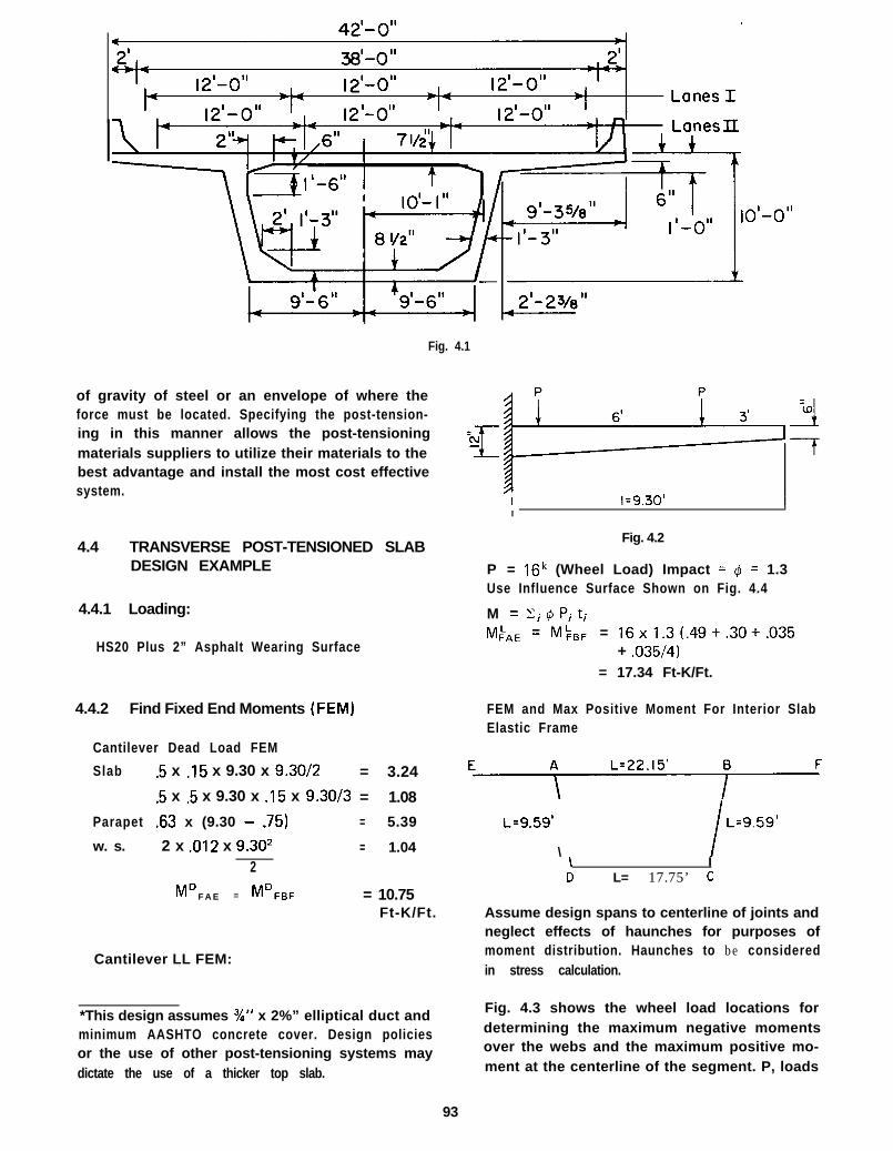
Fig. 4.1
of gravity of steel or an envelope of where theforce must be located. Specifying the post-tension-ing in this manner allows the post-tensioningmaterials suppliers to utilize their materials to thebest advantage and install the most cost effectivesystem.
4.4 TRANSVERSE POST-TENSIONED SLABDESIGN EXAMPLE
4.4.1 Loading:
HS20 Plus 2” Asphalt Wearing Surface
4.4.2 Find Fixed End Moments (FEM)
Cantilever Dead Load FEM
Slab .5 x .15 x 9.30 x 9.30/2 = 3.24
.5 x .5 x 9.30 x .15 x 9.30/3 = 1.08
Parapet .63 x (9.30 - .75) = 5.39
w. s. 2 x .012 x 9.302 = 1.042
MD FAE = ~~~~~ = 10.75Ft-K/Ft.
Cantilever LL FEM:
*This design assumes 3/o” x 2%” elliptical duct andminimum AASHTO concrete cover. Design policiesor the use of other post-tensioning systems maydictate the use of a thicker top slab.
I
Fig. 4.2
P = 16k (Wheel Load) Impact = q? = 1.3Use Influence Surface Shown on Fig. 4.4
M = Ci@Pjtj
MFbE = ML,,F = 16x1.3(.49+.30+.035+ .035/4)
= 17.34 Ft-K/Ft.
FEM and Max Positive Moment For Interior SlabElastic Frame
IE\
L=9.59’
\ I L=9.59’
\ ID L= 17.75’ c
Assume design spans to centerline of joints andneglect effects of haunches for purposes ofmoment distribution. Haunches to be consideredin stress calculation.
Fig. 4.3 shows the wheel load locations fordetermining the maximum negative momentsover the webs and the maximum positive mo-ment at the centerline of the segment. P, loads
93

- --
I
4I 1.08’ I I .08’
*
4 22 .15 ’ b
Fig. 4.3
are used to compute the negative moment andP, loads for positive moment.
Dead Load
Slab & W. S. = .118 K/l
M;,, = MF,, = -!?!I? = .118 x 22.152
12 12= 4.82 Ft-K/Ft.
4.4.3 Max Negative Moment
Use influence surface #16 (Fig. 4.5)Assume wheel print = 8” x 20”.
Equivalent Uniform Load = P, =16
1.29 x 2.29= 5.42 K/FT2(See Sec. 4.3.3)
877 M&n = /3, P” L2 + P;X,
8, = Volume under influence surface(3, = 1x.058x.103x7 = .0418
MFLBA = 1/8n[.0418 x 5.42 x 22.152 + 16 x 1.3(4.5 + .55 + .25 + .55/4 + .25/4)1
= 8.97 Ft-K/Ft.
Mkas (Use Fig. 4.6) = 1/877[16 x 1.3 (.5 + .038+ .15 + .3 + .9 + 3.711
= 4.65 Ft-K/Ft.
Max Positive Moment (Fig. 1)
%A, = %,A = 1/87r[16 x 1.3 (.35+ .088+ .5 + -125 + 2.5 + 5.5)1
= 7.5 Ft-K/Ft.
FEM Due to Wt. of Bottom Slab
w = .15x .708 = .106 K/l
,,,,~,, = Mp,, = “O6 xl;7-752 = 2.78 Ft-K/Ft.
4.4.4 Results From Moment Distribution
M = MD+MLM A E = -10.75 - 17.34 = -28.09 Ft-K/Ft.M A B = - 5 . 7 7 - 11.89 = -17.66 Ft-K/Ft.
To determine the positive moment at the center-line of the segment a longitudinal distributionof a wheel load must be determined. This dis-tribution can be approximated from the fixedend moments obtained from the influence surface.(See Fig. 4.8)
M FAB = MFsA =P x 8.08 x 14.082 +
22.152P x 14.08 x 8.082
22.152
M FAB = MFAB = 7.5 Ft-K/Ft. (from influencesurface)
7.5 = 3.26P + 1.87PP = 1.5 Kips/Ft.
Now the shear diagram for the middle part ofthe segment can be drawn. (See Fig. 4.9)
From moment distribution:
M A B = +5.77 + 6.04 = + 11.81 Ft-K/Ft.M BA = -5.77 - 6.04 = -11.81 Ft-K/Ft.
+ M = 2.8 x 11.07 - .5 x .118 x 1 1 .072 -3 x 1.5 - 11.81
= 7.45 Ft-K/Ft.
8 . 0 8 ’ _,_ 6 ’ I_ 8 . 0 8 ’
Fig. 4.8
94

I I Ix
3
d=l d=2
t LJ
Gerade
K~P$J~..
/
m3x
Fig. 4.4

I I
P.--m-.-
MFf3A
Fig. 4.5

-=i-iI-
2 -
-
I-
r
--------+- ________; ______ ----j--------~ / I II I I 1 I I f-
---
-=-
-
---
MFAB
Fig. 4.6

=
-
(0 -03
-
- $s+&&$-. ---_ -__ _----- -----\- 5---_---___ -- 1_-------- ;---;--::I----- ______ + _____ -----Fig. 4.7
1I- +1-

II.81 ‘K/I f8.08 ’ 6 ’ J 8 . 0 8 ’
L=22.15’W=.ll8’!/1
2 . 8 -
Fig. 4.9
3 I I.81 ‘K/1
1.31.5.53
- 2 . 8
4.4.5 Secondary Moment Computation
Secondary moments will occur only betweenthe webs due to the ability of the cantilevers tofreely rotate. Also, the friction loss in thetendons can usually be neglected due to theshort length and small curvature. However,friction losses and anchor seating losses may be
incorporated in the following computationsby reducing the tendon force in each section bythe amount of applicable friction and by anchorseating loss.
Cut out the middle section and plot the actual
tendon path and 2 diagram. Neglect haunches.El
3.5’4--estraight
15.15’ I, 3 . 5 ’ L1parabolic straight
e - 1 .25 -1 .25 -.674 +.395 +I.037 ‘ 1 . 2 5 ‘ 1 . 0 3 7 +.395 -.674 - 1 . 2 5 - 1 . 2 5
PeEl
0 .I .2 .3 .4 .5 -6 -7 -8 .g 1.0
99

Area Moment of E DiagramEl
Section
1 . -.I x 1.252 . -.5 x .576 x .I3 . -.674 x .I4. -.5 x .674 x .065. +.5 x .395 x .046. +.395 x .l7. +.5 x .642 x .I8. +I .307 x .I9. +.5 x .213 x .I
10. +.5 x .213 x .I11. +I .037 x .I12. +.5 x .642 x .l13. +.395 x .I14. +.5 x .395 x .0415. -.5 x .674 x .0616. -.674 x .I17. -.5 x .576 x .I18. -1.25 x .I
Rotation at the webs would be:
-.0476 PL* -.0476 PLen = eB =
EIL = El
Area
-.125-.029- .067-.020+.008+.039+.032+.104+.011+.Ol 1+.104+.032+.040+ .008-.020-.067-.029-.I25
The negative sign indicates a counter clockwiserotation at the joint. Therefore, the restrainingmoment will cause tension on the top at thewebs. This is opposite to the general tendency ofsecondary moments so a sign convention has tobe rigidly followed.
Determine secondary moment necessary torotate back to zero slope.
es =l/6 M,, L + 1/3M,, L
E l El
en =l/6 M,, L + l/3 M,, L
El El
.0476 PL = l/6 M,s L + 1/3M,s L
El El El.0476 PL = 1/6M,, L . + 1/3M,, L
El El ElSolving simultaneously results in:
M B S = .095 P/12 = .008PM AS = .095 P/l2 = .008P
Distribute Secondary Moments around the box.Results are as follows:M AB = -.0064PM B A = -.0064P
X .05X .I33X .I5X .22X .287X .35X .367X .45X .467X .533X .55X .633X .65X .713X .780X .85X .867X .95
4.4.6 Post-Tensioning Requirements
Arm
-6.25 x IO3 F-3.83
-10.11- 4 . 4 5+2.27
+I 3.82+I 1.78+46.66
+4.97+5.68
+57.04+20.32+25.67+5.63
-15.77-57.29-24.97
-118.75PL2
-47.58 x lo3 -El
Critical Sections
Fig. 4.10
f: = 5,500 psiAllowable Service Tension = 6 fl= 444 psiAllowable Service Compression = .4f: = 2000 psi
Tension is Negative; Compression is Positive
(A) Section I
A = 12 x 12 = 144 in2 e = 6 -2.5= 3.5 in.
s = l2xl22= 288 in3
6M = 28.0gFTKf = 28.09 x 12
= 1.17 KSI288
100
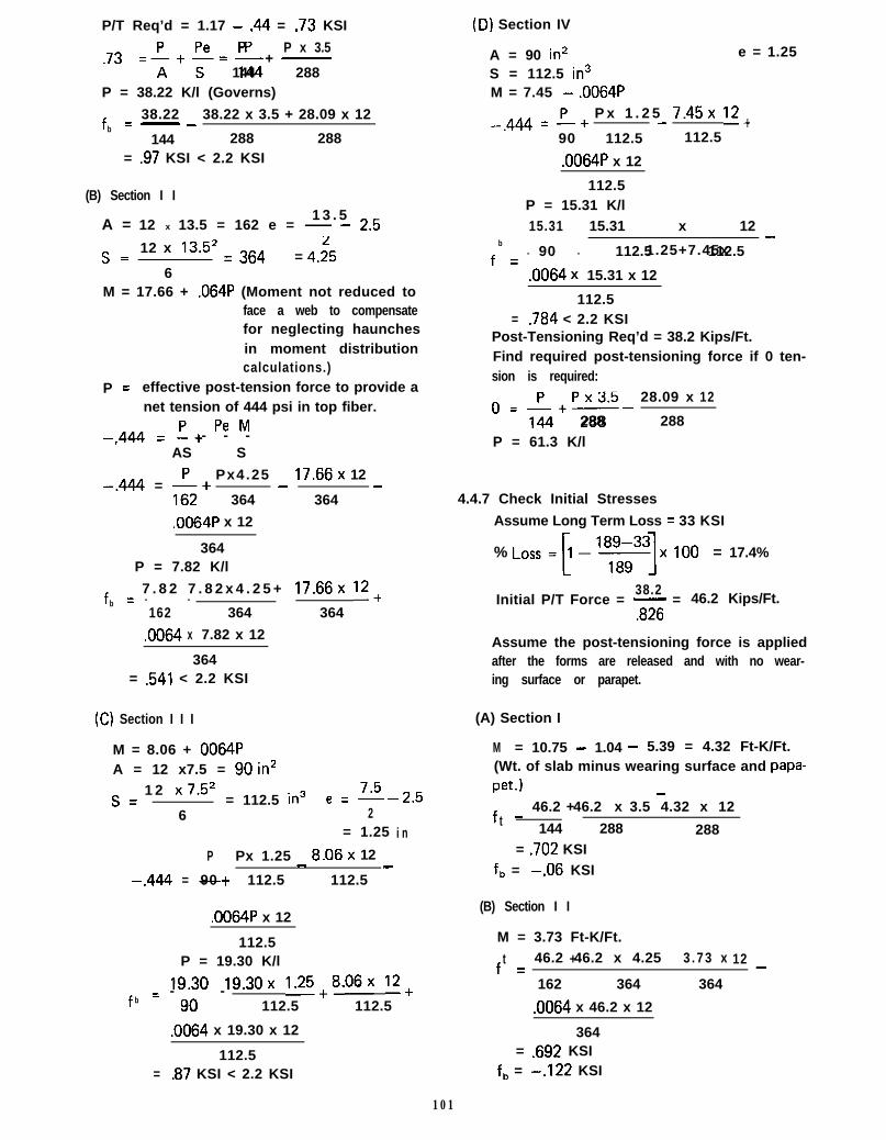
P/T Req’d = 1.17 - .44 = .73 KSI
.73 z;++ -p +P x 3.5
144 288P = 38.22 K/l (Governs)
f = 38.22b- - 38.22 x 3.5 + 28.09 x 12
144 288 288= .97 KSI < 2.2 KSI
(D) Section IV
A = 90 in* e = 1.25
S = 112.5 in3M = 7.45 - .0064P
-.444 = p+P x 1 . 2 5 7.45x 12+-
90 112.5 112.5
.0064P x 12
(B) Section I I
A = 12 x 13.5 = 162 e = - - .1 3 . 5 25
s= 12 x 13.5* = 364= 4.;5
6M = 17.66 + .064P (Moment not reduced to
face a web to compensatefor neglecting haunchesin moment distributioncalculations.)
P = effective post-tension force to provide anet tension of 444 psi in top fiber.
-.444 = I+ Pe M- - -_AS S
-.444 = -&+Px4.25 17.66x 12
364 - 364 -
.0064P x 12
364P = 7.82 K/l
fb
= 7 . 8 2 7 . 8 2 x 4 . 2 5 + 17.66x 12+- -162 364 364
.0064 x 7.82 x 12
364= .541 < 2.2 KSI
(C) Section I I I
M = 8.06 + 0064PA = 12 x7.5 = gOin*s = 1 2 x7.5*
= 112.5 in3 e = E-2.56 2
= 1.25 i n
P Px 1.25 8.06x 12
-.444 = -+ - -90 112.5 112.5
.0064P x 12
112.5P = 19.30 K/l
f = 19.30 19.30x 1.25+8.06x 12+- -b 90 112.5 112.5
.0064 x 19.30 x 12
112.5= .87 KSI < 2.2 KSI
112.5P = 15.31 K/l
f
15.31 15.31 x 12
-b
= - - 1.25+7.45x90 112.5 112.5
.0064 x 15.31 x 12
112.5= .784 < 2.2 KSI
Post-Tensioning Req’d = 38.2 Kips/Ft.Find required post-tensioning force if 0 ten-sion is required:
P x 3.5&+--
28.09 x 120 =
288 288P = 61.3 K/l
4.4.7 Check Initial Stresses
Assume Long Term Loss = 33 KSI
% Loss +-lygqx 100 = 17.4%
38.2Initial P/T Force = - = 46.2 Kips/Ft.
.826
Assume the post-tensioning force is appliedafter the forms are released and with no wear-ing surface or parapet.
(A) Section I
M = 10.75 - 1.04 - 5.39 = 4.32 Ft-K/Ft.(Wt. of slab minus wearing surface and papa-pet.1
46.2 46.2 x 3.5 4.32 x 12ft
_ + -
144 288 288= .702 KSI
f, = -.06 KSI
(B) Section I I
M = 3.73 Ft-K/Ft.46.2 46.2 x 4.25 3 . 7 3 x 12f +
-
t =
162 364 364
.0064 x 46.2 x 12
364= .692 KSI
f, = -.122 KSII
! 101

(C) Section I I I
M = 1.50 Ft-K/Ft.f _f 4 6 . 2 + 4 6 . 2 x 1.25 1.5x 1 2
-90 112.5 112.5.0064 x 46.2 x 12
112.5= .835 K S I
f, = 0.191 KSI
(D) Section IV
M = 2.02 Ft-K/Ft.f 4 6 . 2 + 4 6 . 2 1 . 2 5x 2 . 0 2 1 2x-
b= +
90 112.5 112.5.0064 x 46.2 x 12
112.5= .843 K S I
f, = .184 K S I
Required concrete strength for post-tension.ing:
.55 fci = 843 psi or 7.5 a= 122 psifci = 1533 psi fci = 265 psi
4.4.8 Ultimate Strength Design
For ultimate strength analysis, assume ten-dons are made of 4-‘I~“@-270 KSI strands witha 33 KSI long term loss (1”~-150 KSI barswith 23 KSI loss could also be assumed.)
f, = .7 x 270 -33 = 156 KSIF = 156 x 4 x .153 = 95.5 K/TendonSpacing = 95.5138.2 = 2.5 FT.A* = 4 x . 1 5 3
5 = .24 in2/FT.2 . 5 0
Req’d M, = y[D+5/3(L+ljl+M,
w h e r e I#I = .9
MS = Secondary Moment
(A) Section I
Req’d M, = 1.44 (10.75 + 5/3 x 17.34) + 0= 41 .62F’-K
d = 12 - 2 .5 = 9 .5”
P * = .24= .0021
12 x 9.5
xf;= 2 7 0 ( 1 - .5 .0021 x 2 7 0 1
5.5= 256 KSI
12M, = .24x256x9.5x
(1 - .6 x .0021 x 256 1
M, (Provided) = 45.,““K > 41.6F’-K
(B) Section I I
Req’d M, = 1.44 (5.77 + 5/3 x 11.89) •t.0064 x 38.2
= 37.09 Ft-K/Ft.d = 13.5 - 2.5 = 11”
.24p” = = .0018
1 2 x 1 1.5 x .0018 x 270
f:, = 270 (1 - 1 I5.5
= 258 KSI12 M, = 24 x 258 x 11
(1 - .6x.0018x258 15.5 ,
M, (Provided) = 53.9 1 K/l > 37.09 Ft-K/Ft.
(C) Section III
Req’d M, = 1.44 (3.21 + 5/3 x 4.85) +.0064 x 38.2
= 16.5 Ft-K/Ft.d = 7.5 - 2.5 = 5.0”
P”.24= - = .0040
1 2 x 5
f& 270 (1 - .5x
.0040 x 2 7 0= 15.5
= 243.5 KSI
243.5P*+ = .~cMOx- = .177 < .30
c 5.5
12M, = .24 x 243.5 x 5x
(1 - .6x .0040 x 243.5
15 . 5
M, (Provided) = 21.76F’-K > 16.5F’-K
(D) Section IV
Req’d M, = 1.44 (1.50 + 5/3 x 6.07) -.0064 x 38.2
= 16.5Ff-KM, (Provided) is the same as Section I I I =
21.76F’-K > 16.5Ft-K
102

4.4.9 Other Design Considerations
The preceding design method will be sufficientfor the transverse design of the top slab for seg-ments of normal proportions and span lengths.These proportions are included in a publicationentitled, “Tentative Design and ConstructionSpecifications for Precast Segmental Box GirderBridges” which was prepared by the PCI BridgeCommittee and published by the PrestressedConcrete Institute (PC1 Journal, July-August1975).
However, this design method assumes that therigid frame is supported at the bottom cornerswhich is not precisely true. This assumptionwill effect the web stresses and will usually beinsignificant for the transverse design of the topslab. A more rigorous analysis may be accom-plished with available computer programs.
Another consideration on very wide segmentsis the top slab shortening due to the post-tension-ing force. The slab shortening will induce a momentin the webs some of which will be distributed backthrough the rigid joints.
The following is the computation of the second-ary moments in the design example due to post-tensioning shortening.
A = Deflection due to P/T
A =!iA E
P =
L =
E =A =
A =
FEM =
38.2 k/ft (from previous example)
19.62- = 9.81 ft.
233 x 150’5 ,/35DCj- = 4.5 x lo3 KSI7.5 x 12 = 90
38.2 x 9.81= .0009 ft. = .Ol in.
4.5 x lo3 x 90
6ElA
L2
I12 x 153
w e b = = 3375 in.412
E = 4,500 KSIA = .Ol in.L = 8.37 ft.
FEM =6 x 4 5 0 0 x 3 3 7 5 x . 0 1 = 753FT-K
8.372 x 1728
The fixed end moments of 7.53 FT-K is dis-tributed around the box resulting in the followingmoments:
M AB = MBA = .84 FT-K
This would result in a design moment at SectionII equal to 18.5 + .0064P instead of 17.66+ .0064Pwhich represents an increase of about 4%.
The above computation is a simple procedureand should be included in the transverse slab designwhen the designer has any doubts about the short-ening effects. Generally, the shortening effectsshould always be included when the structurewill carry three or more lanes of traffic.
4.5 SUMMARY
The design example illustrates the simplicity ofthe design of transversely post-tensioned topslabs for both segmental box girder and multi-webcast-in-place box girder bridges. With the adventof crack control criteria and fatigue checks in theAASHTO Specifications for reinforced concretedesign, a post-tensioned design may require nomore effort than a conventionally reinforceddeck. Use of influence surfaces is recommendedfor the determination of moments for segmentaldesigns but AASHTO provisions may be used forthe moment calculations of conventional multi-web box girder bridges.
It is possible, in most cases, that both greaterdurability and decreased cost can be achieved bytransverse post-tensioning. Even if a reducedinitial cost is not realized, the use of transversepost-tensioning is believed to be cost effectivefrom the standpoint of improved durability andreduced maintenance cost.
4 . 1
4.2
4.3
4.4
4.5
4.6
References
AASHTO, “Standard Speci f icat ions for HighwayBridges,” Eleventh Edition including Interims, TheAmerican Association of State Highway and Trans-portation Officials, Washington, DC. 1975.Pucher, Adolf, “influence Surfaces of Elastic Plates,”Fourth Revised Edition, Springer-Verlag, New York1973.Homberg, Hellmut, “Fahrbahnplatten mit Verader-lincher Dicke,” Spr inger -Ver lag , New York 1968.O’Neil, Edward F . , “Durabi l i ty and Behavior ofPrestressed Concrete Beams,” Technical Report No.6-750, Report 4, February 1977 U. S. Army EngineersWaterways Experiment Station, Vicksburg, Mississippi.
Warner, R. F. and Hulsbos, C. L., “Probable FatigueLife of Prestressed Concrete Beams,” PCI Journal,Vol. II, No. 2, April 1966.Hawkins , Ne i l M . “Fatigue Design Considerationsfor Reinforcement in ConcreteJournal, Vol. 73, Feb. 1976.
Bridge Decks” ACI
103

CHAPTER 5CAST-IN-PLACE SEGMENTAL CONSTRUCTION
5.1 INTRODUCTION
American experience in cast-in-place, post-tensioned, segmental construction has been de-veloped only in recent years. The first bridgeconstructed by this means in North America wasSte. Adele Bridge completed in Quebec, Canadain 1964. The Knight Street Bridge in Vancouver,British Columbia, Fig. 5.1, was completed in 1973.Since that time, other bridges have been built byclassical cast-in-place segmental procedures alongwith several bridges utilizing modified cast-in-placesegmental procedures. Some of these structuresand methods are discussed in detail later in thischapter. Detailed information on precast, post-tensioned, segmental construction can be foundin the “Precast Segmental Box Girder BridgeManual published by the Post-Tensioning Instituteand the Prestressed Concrete Institute.
The classical cantilever method of cast-in-placesegmental construction does not utilize falseworkother than possibly immediately adjacent to thepier. The bridge is constructed by cantileveringsegments in a balanced manner from the pier.Construction is initiated by casting a short portionof the superstructure on top of a pier and attach-ing formtravelers on either side (See Fig. 5.2).The formtravelers carry the forms and constructionloads, for the next segments and progress in bothdirections outwardly from the piers, segment bysegment as construction proceeds. The spans arecompleted and continuity may be provided by aclosure pour, hinge or drop-in girder at the centerof the span.
Cantilever construction was first used in Europein 1950. It has since been perfected by the designand construction of several hundred bridges.Many variations of the basic concept have beendeveloped to adapt the method to specific condi-tions of a project.
Segmental cast-in-place construction offers somespecial features which are advantageous over con-ventional cast-in-place construction on falsework.The advantages are:
1. Falsework is not required.
2. The repetitive cycle of fabricating like seg-ments facilitates training of a constructioncrew and produces high labor productionrates.
3. Formtravelers, equipped with hydraulic andmechanical devices for form stripping,
moving, and resetting, mechanizes the form-ing procedures.
4. Each segmental form as well as other equip-ment is used many times resulting in lowforming material and equipment cost.
These advantages make post-tensioned, cast-in-place segmental bridge construction most economi-cal under the following conditions:
1. Where difficult terrain makes falsework con-struction or movement of large pieces ofequipment and material very expensive oreven impossible.
2. Where clearance requirements for ships,rail or street traffic or environmental restric-tions prohibits the construction of false-work.
3. Where the bridge length allows many repeti-tive segment cycles taking advantage of laborefficiency, lower formwork material costsand elimination of falsework costs.
5.2 DESIGN AND DETAILING
5.2.1 General
The design of cast-in-place segmental bridgesfollows similar procedures used for other pre-stressed concrete bridges. The major exception isthat the analysis must include careful considera-tion of the construction stages along with analysisof the completed structure. When the structureis built in cantilever, the governing constructionstage is normally the completed cantilever with theequipment load at the end and the constructionlive load on one cantilever side. Wind loads, asspecified by AASHT0,‘5.“* should also be takeninto consideration during construction. Detailedanalysis procedures for segmental bridges erectedin cantilever are presented in the “Precast Segmen-tal Box Girder Bridge Manual”‘5.2) publishedjointly by the Post-Tensioning Institute and thePrestressed Concrete Institute.
5.2.2 Variable Depth Girder
Cantilever construction produces a bendingmoment diagram that is nearly parabolic with themaximum moment occurring at the piers. Con-sequently, the use of a parabolically haunchedbridge is very functional because it helps reduce
*Superscripts refer to references listed at the end of the chapter.
105

Fig. 5.1 -The Knight Street Bridge in Vancouver British Columbia
S T A N D
C E N T E R J A C
R O L L E R B E A R I N G
S U S P E N S I O NADDITIONAL
‘FRONTAL UPPERW O R K I N G P L A T F O R M
BKS LIFTING
R E A R G A N G - B O A R D ‘BOTTOM FRONTAL LOWER
F R A M E W O R K W O R K I N G P L A T F O R M
Fig. 5.2 - Schematic of a Typical Formtraveler
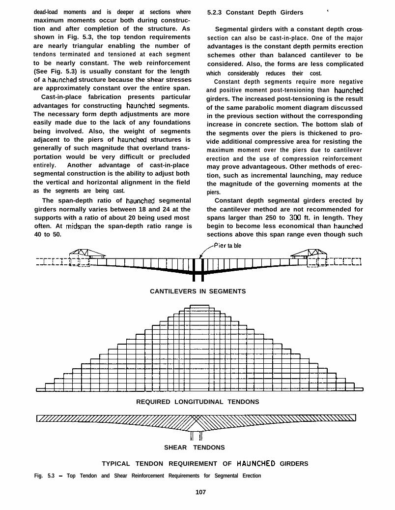
dead-load moments and is deeper at sections wheremaximum moments occur both during construc-tion and after completion of the structure. Asshown in Fig. 5.3, the top tendon requirementsare nearly triangular enabling the number oftendons terminated and tensioned at each segmentto be nearly constant. The web reinforcement(See Fig. 5.3) is usually constant for the lengthof a haunched structure because the shear stressesare approximately constant over the entire span.
Cast-in-place fabrication presents particularadvantages for constructing haunched segments.The necessary form depth adjustments are moreeasily made due to the lack of any foundationsbeing involved. Also, the weight of segmentsadjacent to the piers of haunched structures isgenerally of such magnitude that overland trans-portation would be very difficult or precludedentirely. Another advantage of cast-in-placesegmental construction is the ability to adjust boththe vertical and horizontal alignment in the fieldas the segments are being cast.
The span-depth ratio of haunched segmentalgirders normally varies between 18 and 24 at thesupports with a ratio of about 20 being used mostoften. At midspan the span-depth ratio range is40 to 50.
5.2.3 Constant Depth Girders
Segmental girders with a constant depth cross-section can also be cast-in-place. One of the majoradvantages is the constant depth permits erectionschemes other than balanced cantilever to beconsidered. Also, the forms are less complicatedwhich considerably reduces their cost.
Constant depth segments require more negativeand positive moment post-tensioning than haunchedgirders. The increased post-tensioning is the resultof the same parabolic moment diagram discussedin the previous section without the correspondingincrease in concrete section. The bottom slab ofthe segments over the piers is thickened to pro-vide additional compressive area for resisting themaximum moment over the piers due to cantilevererection and the use of compression reinforcementmay prove advantageous. Other methods of erec-tion, such as incremental launching, may reducethe magnitude of the governing moments at thepiers.
Constant depth segmental girders erected bythe cantilever method are not recommended forspans larger than 250 to 300 ft. in length. Theybegin to become less economical than haunchedsections above this span range even though such
/Pier ta ble
-f--r-f--?-L-L-L.,*
CANTILEVERS IN SEGMENTS
REQUIRED LONGITUDINAL TENDONS
SHEAR TENDONS
TYPICAL TENDON REQUIREMENT OF HAUNCHED GIRDERS
Fig. 5.3 - Top Tendon and Shear Reinforcement Requirements for Segmental Erection
107
girders have been used for architectural reasonson some longer spans.
For maximum economy, the span-todepthratio for constant depth structures should be 18to 20. However, span-todepth ratios of 20 to30 have been used when required for clearancesor aesthetics. Of course, shallower depths requirethe use of more post-tensioning steel so the con-crete versus post-tensioning costs should be eval-uated.
It is not advisable to make the girder too slenderon long span bridges. If the depth at the piers istoo small, the bottom slab near the piers becomesvery thick which may produce constructionproblems. Also, the deflections under live load,which are not normally a consideration, will berelatively large; and the bridge may become sen-sitive to vibrations from traffic or wind. Thedeeper-girder sections are, also, less sentitive tolong-term creep deflections under dead loads.
5.2.4 Cross-Section
The number of webs in the cross-section shouldbe kept to a minimum. Using the minimum possi-ble number of webs reduces the forming areas andmakes possible efficient use of the mechanizedforms. These factors usually lead to the use ofsingle-cell box girders with large roadway slaboverhangs of up to 15 ft. or longer. In order toachieve this, transverse post-tensioning becomesadvisable. The advantages of transverse post-tensioning of deck slabs and a detailed designexample are presented in Chapter 4.
Wide bridges of 55 ft. or more may utilizetwo or more boxes fastened together with aclosure strip. These boxes may be transverselypost-tensioned individually or the tendons may beextended from one side of the superstructure tothe other so that the closure pours are also pre-stressed. However, in the latter case, care should beexercised to make provisions for transitioning thetendons from one box to another through theclosure pour. This requires very exacting alignmentand conduit placing controls.
Sloping the exterior webs proves to be advanta-geous for cast-in-place segmental girders of constantdepth but is more difficult and costly if the girdersection is haunched. For constant depth structures,inclined webs facilitate the stripping and resettingof forms by the lowering and raising of the form-travelers which reduces the amount of labor in-volved. While this is also true for haunched struc-
tures,. the labor savings is more than offset by theaddrtronal form and labor costs involved in adjust-ing the forms for the narrower bottom slab widthwhich occurs as the depth of the girder increases.Also, the compression area represented by thebottom slab over the piers gets smaller in the areawhere it is most needed. However, haunchedgirders with inclined webs can be and have beenbuilt. The additional expense is usually justifiedby aesthetic considerations.
The design of webs for cantilever bridges withspans over 250 to 300 ft. in length perferrablyshould be done in such a manner that the concretein the webs remains untracked under service loads.This is possible only if the webs are prestressed.Proper camber control requires known cross-sectional properties, such as area and moment ofinertia; and unless the webs are prestressed, shearcracks may occur as construction progressesresulting in possible problems relative to cambercontrol. For this reason, it is very desirable thatthe webs be prestressed with vertical or inclinedtendons, called “shear tendons”, anchored in thetop and bottom slab. Even though they reduce theshear stresses in some areas, curved longitudinaltop tendons extending into the webs generallycannot be used as shear reinforcement, becausethey are normally anchored above the bottomflange. Under ultimate conditions, the compressionregion is at the very extreme fiber of the bottomslab (negative moment area) and the shear rein-forcement can be effective only if it is anchoredwell inside the compression zone. Special pro-visions, such as specifying bar tendons or poweranchor set on strand tendons, should be made toassure the anchorage losses of the relatively shortweb tendons are minimized.
Shear tendons are designed in the same way asregular stirrups, but with a larger ultimate stresswhich should be limited to 60 ksi above the effec-tive prestress, or the yield strength of the stirrupmaterial, whichever is smaller. Limiting the stressin this manner makes the elongation of the sheartendons compatible with non-prestressed stirrupshaving a yield strength of 60 ksi. It should benoted that for spans in excess of 250 ft. in length,the CEB-F I P design recommendations (5.3) may bemore applicable than either ACI or AASHTO.
The roadway slab is normally designed with theaid of influence surfaces. An example of thetransverse design of the top slab of a cast-in-placesegmental girder is contained in Chapter 4. Theexample also includes the moment distributionwhich yields the transverse design moments forthe bottom slab.
108

5.2.5 Diaphragms
AASHTO Specifications specify diaphragms atrelatively small intervals in box girders. However,practice has proven that they are seldom requiredin segmental box girders unless the bridge issharply curved and diaphragms are needed toprovide torsional rigidity. The omission of inter-mediate diaphragms facilitates the use of form-travelers since the diaphragms would interferewith the repetitive construction cycle. Practicallyall of the recent long-span, cast-in-place segmentalbridges have diaphragms provided at only thepiers and hinges.
The omission of intermediate diaphragms re-quires that torsional moments must be transferredthrough bending of the slabs and webs. This loadtransfer is similar to that in a closed frame. Theresulting additional bending moments in the topand bottom slabs and in the webs are normallysmall, requiring only a small increase in transversedeck and web reinforcement.
5.2.6 Longitudinal Tendon Layout
Tendon sizes for cast-in-place segmental bridgesshould be limited to effective prestress forcesof about 350k (12%” strands), and the tendonsshould be bonded (grouted). The largest single-bar tendons available will provide about 166kper tendon at 70 percent of their ultimatestrength. The reason for this limitation is that thetendons are usually anchored in thin sections(either top or bottom slab or the webs), and theanchorage requirements make the use of larger ten-dons impractical (for typical applications).
Longitudinal tendons for cantilever erectionmay be grouped according to their function.(Negative moment or erection tendons and posi-tive moment or continuity tendons). The tendonanchorages for cast-in-place construction aregenerally located in the top and bottom flangesresulting in straight tendons. The tendons mayalso be anchored in flares or recesses, but theseshould be avoided if possible due to the increasedforming requirements. The negative (top) andpositive (bottom) moment tendons should alwayslap each other by one or two segments to providefor adequate stress transfer.
Different methods of erection require differentamounts and distributions of longitudinal tendonsduring construction. However, the tendon require-ments in the completed structure to resist serviceload stresses are similar for all erection methods.
Therefore, the difference in tendon requirementsfor various erection methods is a function of thetendon requirement for construction stresses. Thisfact should be kept in mind by the designer as thestructure is detailed, as discussed below.
5.2.7 Details
The discussion of construction plans in Section3.1 is fully applicable to cast-in-place segmentalbridges. The plans should recognize all of theconstruction options available to the contractorincluding alternate post-tensioning systems dis-cussed in connection with cast-in-place construc-tion on falsework and, as stated in Section 3.1,alternate methods of erection and alternate seg-ment lengths. The primary function of the contractplans is to set forth the final stress requirementsof the bridge and to provide a basis for reviewingand approving fabrication and erection plans.Unless both of these functions are accomplishedduring the preparation of the contract plans, theplans may become useless as the project progresses.
An erection scheme and a segment length mustbe assumed during design to ensure that thebridge can be constructed. The best erectionscheme to assume is probably balanced cantilevererection unless there is reason to believe that someother method might be more enconomical. In anycase, the specified erection stresses should bepresented in the form of stress envelopes whichpermit a variation of the segment lengths. Like-wise, the post-tensioning requirements should bepresented in terms of a center of gravity of steelor a resultant force location and a required forcewhich corresponds to the stress envelopes previ-ously mentioned. The reason for these generallimitations in the contract plans is that modifi-cations of the segment length assumed in thedesign affect the post-tensioning details. Forthis reason, it is best to have the contract plansdetailed so that they can be easily related tovarious erection schemes. For this purpose, thestress conditions and post-tensioning require-ments, upon completion of the structure, canbe presented in a similar manner to that discussedin Chapter 3.
Alterations of the cross-section, for variousconstruction alternates, should be allowed. Thisis usually accomplished through constructionspecial provisions rather than by providing detailson the plans. The construction specifications canpermit modification of the cross-section withoutaltering the exterior dimensions if it is believedthat the exterior dimensions should not be altered
109

for aesthetic or other reasons. The stress envelopesdiscussed in the previous paragraph will still beeffective for reviewing the fabrication plans evenif the section properties are different. Requiringplots of both construction and final stresses on thefabrication or erection plans, facilitates the reviewby enabling the reviewer to spot check any dis-continuities prior to making a comparison with thecontract plans.
In summary, the contract plans should be asgeneral as possible, and should be more concernedwith final completed conditions than the inter-mediate construction conditions. In contrast, thefabrication or erection plans should be as specificas possible and should reproduce many of the samedesign parameters which appear on the contractplans to aid in the review process.
5.3 CAST-IN-PLACE CONSTRUCTIONOPTIONS
This section discusses several construction op-tions available for cast-in-place segmental bridges.The discussions are based upon actual projectswhich have been completed. The original designsfor all of the projects were based on balancedcantilever construction and most included theoption of either precasting the segments or castingthem in place.
5.3.1 Cantilever Supported by Falsework Bents
The Napa River Bridge, located just south of thecity of Napa, California, was bid with three con-
struction alternates available. The bid alternateswere as follows:
1 .
2 .
3 .
Cast-in-place lightweight concrete continu-ous prestressed box girder superstructurewith continuous parabolic draped tendons.Structural steel box girder composite with alightweight concrete deck.Segmental prestressed lightweight concretebox girder.
The segmental prestressed concrete alternateincluded both cast-in-place and precast super-structure options, so four basic superstructuretypes were actually permitted. Further, the useof falsework was permitted for the segmentalprestressed concrete box girder alternative at thecontractor’s option.
The winning contractor’s bid was based on thecantilever cast-in-place option, and he also choseto use falsework bents to support the cantileverspans during construction. Fig. 5.4 is a photo-graph of the nearly completed bridge. Fig. 5.5shows an elevation view of the span arrangementand also the cross-section which was used.
The superstructure was erected by castingbalanced cantilevers supported by falseworktowers with ten 70-ft-long, 36-in. deep wide flangegirders spanning between towers. All of the form-work including the steel girders and timber formswere lowered with winches attached to the canti-levered girder after all of the negative post-tension-ing tendons were stressed. The spans were closedat midspan by a closure pour prior to installing thepositive post-tensioning tendons. Some of thelonger spans were completed by a segment cast
Fig. 5.4 - Several Completed Spans of Napa River Bridge

Total length of bridge =2230-O” Measured along “5” line
navigation channelELEVATION
barr ier
TYPICAL BOX SECTION
Fig. 5.5 - Elevation and Cross-Section of the Napa River Bridge
on falsework suspended from the cantileveredboxes on each side. For instance, approximately60 ft. of the 250-ft river span was completed inthis manner with three segments.
The advantage of this erection method overconventional cast-in-place on falsework is that boththe forms and falsework bents could be reusedfor all of the segments. Also, a U. S. Coast Guardrequirement that a 70-ft.-wide by 70-ft.-highnavigation channel be maintained prohibitedfalsework across the river. The advantage overbalanced cantilever erection was the contractordidn’t have to invest in form travelers. The materialused for the forms and the falsework bents waseither on hand or readily available. Other con-siderations included the relatively short spans foruse of form travelers, and the segments would havebeen wide and heavy if precast.
The post-tensioning contractor used a longi-tudinal loop tendon system for its efficiency andeconomy. The 12-strand tendons extended from
111
the end of one cantilever to the other cantileverwhere it looped around and came back. Theanchors for the tendons were located in anchorblocks cast into the bottom slab or the top deckso that all stressing was done from the inside ofthe box. The deck was also post-tensioned trans-versely allowing a lo-ft. overhang of the deck oneach side of the three-stem box girder. The trans-verse post-tensioning in the deck slab permittedreduction of the number of girder stems to threeas compared to the seven stems required for theconventional cast-in-place, prestressedconcrete al-ternative. The minimum number of stems availablein the winning alternate forced most of the longi-tudinal prestressing into the slabs. The net resultwas a reduction in formed surfaces and maximumprestress eccentricities which resulted in a veryeconomical structure. The plans showed theminimum prestress required at each section. Thecontractor had the option of balancing segmentlengths against post-tensioning force to achieve

Fig. 5.6 - 2% x j/ , Flat Ducts for Four-Strand Tendons
the most economical structure.
The segmental prestressed concrete super-structure plans permitted either 270-ksi strand or150-ksi bars, and prestress force diagrams wereprovided in the plans for both materials. All ofthe tendons used on the project were strandtendons. Conventional stirrup reinforcement wasused for shear reinforcement even though theplans permitted a combination of diagonal post-tensioning and conventional reinforcing steel. Thedesigners computed 40,000 psi losses for 270 ksistrand and 28,000 psi losses for 150 ksi bars, butthe contractor was permitted to submit revisedloss values based on tests of the materials plussubstantiating calculations. The magnitude of theprestress losses was influenced by the use of light-weight coarse aggregate.
Precast post-tensioned concrete deck bulbtee.
The transverse post-tensioning consisted of four The State believed that Alternate “B” provided%“, 270K strands in flat ducts measuring 2%” x a more attractive structure in the environment and%“. The strands were flared at the anchorage at gave this alternative a $300,000 advantage wheneach edge of the deck slab by a steel casting that evaluating the bids. As a final attempt to protect
had four holes. The four strands were all stressedindividually using a monostrand jack weighingabout 30 lb. Fig. 5.6 shows the conduit used forthe transverse post-tensioning.
5.3.2 Traveling Truss
The Denny Creek Bridge is located in theSnoqualmie National Forest about 70 miles east ofSeattle, Washington in the Cascade Mountains. Thelocation is in the heart of an ecologically sensitivearea which dictated that the structure had to beaesthetically pleasing and had to avoid damage tothe environment.. Consequently, the structurecould not be erected on ground-supported false-work. Also, the stringent restrictions on haulroads and work areas made a cast-in-place seg-mental method a preferable solution. However,the Washington Department of Highways offeredthree alternate designs on which contractorscould submit proposals. The alternatives were asfollows:
Alternate ACast-in-place and precast, prestressed, U-shaped box girders.
Alternate BCast-in-place, post-tensioned concrete boxgirder.
Alternate C
68’- 0”
I =-“II ‘0 (7 I
15’- 43/e” 1 3’-6” 1 16’-0” ’I - I -
Fig. 5.7 - Denny Creek Section
112

Fig. 5.8 - Erection Truss Used for Denny Creek Bridge
the delicate alpine vegetation, the State requiredconsideration of the use of a highline for con-struction of the foundations as well as the super-structure on a certain portion of the project. Thiswas later evaluated and found to be too costly.
The winning contractor chose Alternate “B”and submitted a bid of 11.4 million dollars whichwas the low bid without the $300,000 advantage.The bridge consists of 16 spans at 188’ in lengthand 4 spans varying from 143’ 7” to 166’ in length.The box girder (see Fig. 5.7’for cross-section) is9 ft. deep and 16 ft. wide at the bottom withinclined webs and 15 ft. 4-3/8 in. cantileversmaking a total deck width of 52 ft.
Since the spans are all approximately the samelength, the contractor chose the traveling trusssystem shown in Fig. 5.8 for the erection. Thetruss which is 330 ft. in length andweighs 540 tons moves forward span by span asconstruction progresses. The truss was developedin Switzerland and was used to erect the GruyereViaduct there. Denny Creek was the first use ofsuch a system in North America.
The box girder section is cast in the three stages
shown by Fig. 5.9 and in the construction sequenceshown by Fig. 5.10. Stage one is the casting of thebottom and sides of the single-cell box girders.The forms are supported by the traveling trussduring this stage until the concrete is post-tensioned.After post-tensioning, this section supports theforms which are used to cast the other two stages.Stage two consists of casting the top of the deckbetween webs of the box, and stage three involvescasting the cantilever overhangs. The traveling trussis moved forward, as shown by Fig. 5.10, prior tocasting the second stage.
5.3.3 Incremental Launching
Incremental launching is a particularly usefulmethod for constructing cast-in-place segmentalbridges when the piers can be easily located atregular intervals. The superstructure is cast incre-mentally (50 ft. to 100 ft. segments) at one abut-ment and pushed toward the piers segment bysegment. This technique has been gaining accept-ance in Europe and South America since 1959

STAGE I
STAGE 2
STAGE 3
Fig. 5.9 - Casting Sequence for Denny Creek Bridge
-m,.,.. . ;; . . . . . . . . . . , . . . . . . +....I... . . . . : ‘, ..: . . , :
Fig. 5.10 - Construction Sequence for Denny Creek Bridge
114

DIRECTION OF MOVEMENT/FABRICATION AREA LAUNCHING NOSE jrEMPORARY PIER
II
9x’-6” _ 93’-6”
I-_ _ 93’-6” _ _ 93’-6” _ _ 93’-6” - _ 93’-6” _ _ 93’-6” _ 93’-6”
I- I- I- I- I- -l-
93’-6” _ _ 187’-0” 187’-0” 187’-0” 187’-0”I - I-
PIER h i
Fig. 5.11 - Construction Elevation of Incremental Launching
4 5 s
and has now been introduced in the United Stateswith the construction of Indiana’s Wabash RiverBridge which is discussed later.
As shown by Fig. 5.11, incremental launchingdoes not utilize any falsework or erection girders.Instead a structural steel launching nose is usedto prevent cantilever moments from exceeding thedesign capacity. Intermediate, temporary erectionpiers are also often used to minimize stressesduring launching as shown in Fig. 5.11. Thebending moments that occur during the launchingprocess are balanced by central or Stage I post-tensioning, which is installed and stressed prior tolaunching each segment to resist the launchingstresses. This central post-tensioning is also utilizedto offset the stresses that occur after completion ofthe bridge. In addition to the Stage I tendons,Stage II tendons are installed after the launching iscompleted. These tendons provide the necessarycamber for meeting the vertical alignment require-ments as well as providing the required additionalload carrying capacity. The use of the two-tendonsystems at the different erection stages requiresmore post-tensioning than other erection methods.However, the additional cost for post-tensioningmaterials is more than offset by the savings informwork, falsework, and erection equipment.Also, the placing of reinforcement and concretein a stationary bed is normally more economical
than for construction on falsework away from theabutments.
In order to construct bridges by the incrementallaunching method, the horizontal and verticalalignment must either be straight, or of a constantradius of curvature. The radius of curvature shouldbe 250 ft. or greater. Also, the top slab must havea constant crown or constant superelevation with-out any transitions.
Incremental launching requires stringent geo-metrical control at the stationary site becauseerrors in alignment are difficult to correct. How-ever, control of geometry is fairly easy to obtaindue to the fact that the casting bed is permanentlylocated and the instrument can also be perma-nently fixed until the launching operation is com-pleted. When the grade of the bridge is inclined,the superstructure should be launched downwardif possible. With a 2 percent grade, the beam has tobe pushed or held back depending on the coeffi-cient of friction of the bearing faces. The launchingequipment should be able to do both. If the gradeis 4 percent or more, additional safety measuresare recommended.
Incremental launching is best adapted to bridgelengths of 1,000 to 2,000 ft. Bridge lengths up to4,000 ft, may be achieved by launching from bothends.
P I E R 2 3 4 5 6
Fig. 5.12 - Elevation of Span Arrangement for Wabash River Bridge
115

46-6"I +‘co-’0+
=a0J
-f-
Fig. 5.13 - Cross-Section for Wabash River Bridge
5.3.3 (A) Wabash River Bridge
The Wabash River bridge at Covington, Indiana,consisting of four spans at 187 ft. in length andtwo end spans of 93.5 ft. in length for a totallength of 935 ft., was entirely cast and launchedin the summer of 1977. The completed-spanarrangement and cross section are shown by Figs.5.12 and 5.13, respectively. As mentioned pre-viously, this is the first incrementally-launched,box-girder bridge in North America.
As shown by Fig. 5.13, the girder is a two-cellbox 8 ft. deep with a 9-ft. cantilevered deck oneither side and will provide a 44 ft. clear roadwayafter the curbs are cast. It would have been prefer-able to use a cross section with only two webs forthis bridge, but the cross-section details were fixedby the contract plans. The 46 ft. 9 in. segmentswere cast in two stages on the casting bed. Thebottom slab and a portion of the webs were castfirst and then moved forward 46 ft. 9 in. wherethe remainder of the webs and top slab were cast.Fig. 5.14 is a photo taken during construction.
Fig. 5.14 -Wabash River Bridge During Construction

Fig. 5.15 - Launching Jacks
The launching equipment (see Fig. 5.15) com-prised of a hydraulic vertical jack and a hydraulichorizontal jack was located in the abutment area.The 300 ton vertical jack, which slides on a tefloncovered plate and a polished stainless steel sheet, isequipped with a hardened friction element on topwhich comes in contact with the bottom of thebox as the jack lifts the girder about % inch. Thehorizontal jack, which also has a 300 ton capacity,is then used to move the entire structure forwardhorizontally. When the cylinder of the horizontaljack reaches its maximum extension, the verticaljack is released and brought back to its original
position with the horizontal jack. The procedureis repeated until the superstructure is launched byone increment. It’ generally took about 2 hoursand 15 minutes to launch the 46 ft. 9 in. segmentsof the Wabash River Bridge.
As shown by Fig. 5.11, temporary piers werelocated at the midspan of spans two through five.As the girder was being launched, both the tem-porary and permanent piers were equipped withsliding blocks made of 8500 psi concrete with apolished stainless steel sheet bolted to the top ofthe concrete. These are later replaced with perma-nent bearings. As the girder lmoved across thesesliding blocks, laminated teflon-steel-neopreneplates were placed to slide on the stainless steelsheet by inserting them in the launching directionbetween the superstructure and the sliding blockand then removing them after they pass through.The piers were designed for overturning forceswhich would be caused by a 7 percent frictioncoefficient. (The temporary piers were tied back tothe permanent piers with a system of % inch-monostrand, post-tensioning tendons.) However,the friction coefficient actually observed was only3% percent. Normally, the substructure should bedesigned for a friction coefficient twice as large as
expected, and the grade of the bridge’should alsobe taken into consideration.
The post-tensioning tendons were installed intwo stages. Stage I tendons, located in the webs,extend continuously through the complete lengthof the structure and were stressed incrementallywith the aid of coupler anchors as each segmentwas cast. The Stage I tendons provided an essential-ly uniform compressive stress to counteract thetensile stresses occurring during the launching.Stage I I post-tensioning consisted of discontinuoustendons located in the top or bottom slabs at thenegative and positive moment areas. Thesetendons, which were installed after the completionof the launching, were anchored in blockouts caston the inside of the box.
The rate of production for this bridge was aboutone and one third segments or 55 ft. of bridge perweek except for the last few weeks. Toward theend of the job, two segments were cast and launchedeach week. It is interesting to note that the pricefor the incrementally-launched, cast-in-place con-struction was a quarter of a million dollars lessthan the price quoted for precast box girdererected by balanced cantilever, and the bridgewas constructed in one half the time allotted forprecast construction.
5.3.4 Formtravelers
Most of the cast-in-place segmental bridges inNorth America have been erected with form-
travelers, and by either balanced cantilever orcantilevers supported with temporary bents. Thelatest bridges located near Vail, Colorado andconstructed in the summer of 1977 were erectedwith three different erection procedures for fourbridges. As shown by Fig. 5.16, the abutment
5.16 - Abutment Span Construction on Vail Pass Bridge

spans were supported by temporary erection bentsas the travelers moved forward with the centerspans being freely cantilevered from the abutmentspans to a central pier, or to another balancedcantilever coming from a central pier, dependingupon the length of span involved. However, in allcases, the segments were cast with formtravelers.
Fig. 5.2 shows a schematic of a typical form-traveler. The traveler support truss is tied down toa previously cast segment with vertical bars passingthrough the segment. This connection is equippedwith four hydraulic jacks which are adjusted toprovide the correct form alignment. The formsare suspended from the traveler truss with addi-tional adjustments provided for alignment control.As each segment is cured and post-tensioned, theforms are released and the entire traveler is movedforward to cast the next segment.
Each bridge erected by balanced cantileverrequires a minimum of two formtravelers. When-ever the project includes two bridges, the con-tractor will generally use four formtravelers andbuild both bridges simultaneously as was the casefor the Pine Valley bridges in California. The VailPass project included four bridges which the con-tractor erected with six travelers.
The normal cycle time for completing one seg-ment with a formtraveler is five days. The cycletime is directly dependent upon the required con-crete strength and the curing methods. For in-stance, the cycle time for the Vail bridges wasreduced to three days by adding a super waterreducer to the concrete and stressing the tendonswhen the concrete reached 3500 psi. The required28day strength was 5500 psi.
The concrete may be delivered to the forms byany of the conventional methods. Pumping andconcrete conveyors are probably the most commonsince many bridges of this type are built in environ-mentally sensitive areas restricting the movementof cranes. The concrete for the Vail bridges, whichwere erected with temporary bents under theabutment spans, was delivered by backing ready-mix trucks out on to the completed portion of thebridge and depositing the concrete directly into theforms.
Normally, the segment lengths for formtravelersare 10 to 15 ft. in length. Both bar systems andstrand systems may be used for the post-tensioning.The alignment and deformation controls aresimilar to those required for any type of segmentalconstruction, but the required field adjustmentsare more easily made than for a segmentalstructure erected with precast segments.
5.3.5 Segmental Construction on Sliding Forms
The use of segmental construction on slidingforms offers a means of achieving economy in thecost of formwork and falsework for some cast-in-place, post-tensioned bridges. Additional econ-omy is provided because the quantity of concreterequired to be cast at one time can be held to anoptimum amount through adjustment of the seg-ment length. The optimum segment and formlength depends on local conditions and the spanlengths of the bridge. Normal segment lengths mayvary between 40 ft. and 60 ft. The post-tensioningforce is installed in two stages. Initial, partialpost-tensioning is installed after construction ofeach segment to resist any bending stresses thatmight occur due to falsework settlement. Theprimary post-tensioning force is applied uponcompletion of the span in much the same mannera s conventional cast-in-place construction onfalsework. After a span and a portion of thefollowing span have been completed, the falseworkand formwork assembly is moved forward on railsto construct the following span. As illustrated bythe following discussion of the Eel River bridge,the falsework and formwork costs with this methodof construction are a small fraction of the coststhat would be involved using conventional false-work and forming techniques.
5.3.5 (A) Eel River Bridge
The Eel River Bridge, located in the NorthernCalifornia area, was the first bridge constructedin the United States with the sliding form method.The five-span, curved, twin structures consistof spans ranging from 201.5 ft. to 310 ft. inlength. The contractor proposed the sliding formmethod of construction at a material and formingcost saving of $220,000 on the $5.2 million dollarproject. This saving was divided equally betweenthe contractor and the State under the provisionsof a cost incentive program.
The use of transverse post-tensioning in thedecks of the redesigned superstructures permittedincreasing the cantilever of the top slabs from6.5 ft. to 10.5 ft. on either side of the box girdersections along with the elimination of the interiorstem of the boxes. While the redesign increasedthe post-tensioning costs by 40 percent, from$600,000 to $1 million, it saved about 3,000 cu.yd. of concrete and 560,000 Ibs. of reinforcingsteel.
118

Fig. 5.17 - Construction of the Eel River Bridge
The original design would have required 1,400tin. ft. of forming and shoring for each of thebridges which are about 100 ft. above the streambed. The redesign permitted the contractor to useonly two sets of traveling forms, which were each56 ft. in length, and falsework for a span plustwo segments on each bridge, a total of about 800lin. ft. for the entire project.
The 42-ft. long segments used in the Eel RiverBridge were completed at a rate of one segmentevery seven days. Fig. 5.17 illustrates the con-struction process. After each segment was cast andthe concrete reached the specified strength, it waspost-tensioned and the outside formwork waspushed forward to the next segment. The interiorformwork followed after the conventional rein-forcement and tendons for the next segment hadbeen tied in place. The timber and steel forms weredesigned to move to the next forming positionon wheels and rollers. The exterior forms slid onpairs of rails laid on the form soffit with the formlegs being supported by wheels or bogies. Theinterior forms rode on bogies rolling on 8” x 8”timbers attached to the top soffit reinforcingbars.
After the top slab transverse post-tensioning
was stressed in each segment, four longitudinalconstruction tendons were stressed to put thesuperstructure in compression. The remainder ofthe longitudinal tendons were stressed when aspan plus two segments had been completed. Atthis point, the falsework and the formwork weremoved ahead to the next section of the bridge.The number of longitudinal tendons, located inthe top and bottom slabs, and the stems rangedfrom 59 to 104 depending on the span length.
The total minimum falsework requirement onthe Eel River Bridge was about 16 percent of thetotal bridge length and the formwork was about3 percent of the total contact form area.
5.4 DESIGN AND CONSTRUCTION SPECI-FICATIONS FOR CAST-IN-PLACESEGMENTAL BOX GIRDER BRIDGES
This section presents suggested design andconstruction specifications for cast-in-place seg-mental box girder bridges. These specificationsare meant to be supplementary to Standard Speci-fications published by most Departments of

Transportation. When using the specificationspresented in this section, care should be exercisedto determine that the material contained in thereferenced Standard Specifications is not in con-flict with these specifications.
5.4.1 Design Specifications
A . G E N E R A LExcept as otherwise noted in this section,
the provisions of Section 6 - Prestressed Con-crete from the AASHTO Standard Specifica-tions for Highway Bridges, shall apply to theanalysis and design of cast-in-place segmentalprestressed concrete box girder bridges. Deckslabs without transverse post-tensioning shallbe designed in accordance with the applicableprovisions of Section 5 - Reinforced Con-crete. Elastic analysis and beam theory maybe used in the design of cast-in-place seg-mental box girder structures.
B. FLEXURENo longitudinal tensile stress shall occur in
the top of the top deck due to the applicationof construction loads or service loads (D L +LL + I) either during construction or aftercompletion of the structure. Longitudinalbending stresses in all other areas shall be inaccordance with Section 1.6.6.”
Allowable bending stresses in the transversedirection shall be in accordance with Section1.6.6. The top slab shall be designed trans-versely by elastic analysis considering themoment restraint of the webs. Rigid boxframe analysis shall be assumed for thetransverse design of the box girder compo-nents. The analysis shall consider the variabledepth of the deck slab.
The top slab shall be proportioned inaccordance with the stress requirementsexcept that the thickness shall not be lessthan 6 in. The minimum thickness of thebottom slab shall not be less l/30 of theclear span between the webs or ~Y’z in. which-ever is greater. Adequate fillets shall beprovided at both ends adjacent to the webs.The clear span may be taken as the distancebetween the fillets. For this purpose, theslope of the fillets with respect to the bottomslab shall be assumed to be no flatter than1:5.
*Section numbers refer to AASHTO Specifications.
C . S H E A RExcess shear stresses in the webs shall be
carried by web reinforcement consisting ofeither prestressed or nonprestressed stirrups.This reinforcement may be placed vertical orinclined at an angle of not less than 40” fromhorizontal. The required area of the shearreinforcement may be calculated in accord-ance with the following equation:
A = (Vu -V,b,SY
f, (sin OL +cosfI!)
where: A, = area of shear reinforcement.
V, = nominal total design shearstress.
Vc = nominal permissible shearstress carried by the concrete.
b, = width of the web.
S = longitudinal spacing of theweb reinforcement.
f , = specified yield strength of theshear reinforcement.
cl! = angle between inclined webreinforcement and the longi-tudinal axis of the member.
The nominal shear stress carried by theconcrete shall not exceed 0.06 f: or 180 psiwhichever is smaller. The allowable stress innonprestressed shear reinforcement shall notexceed 60,000 psi. The allowable stress in pre-stressed shear reinforcement shall not exceedthe smaller of the following:
1.) yield strength of the tendon2.) effective prestress after losses plus
60,000 psi
The maximum nominal shear stress shallnot exceed 0.35 fi if 45” inclined stirrups areused.
If prestressed shear reinforcement is de-signed to carry the total shear, the minimumamount of nonprestressed shear reinforcementto be supplied shall be computed according tothe following equation:
b,SA, = 50 -
f ”
D. TORSIONIn the design of the cross-section considera-
tion shall be given to torsional stresses re-sulting from eccentric loading or geometry ofstructure. The shear flow due to torsionalmoment shall be combined with the shear
120

forces in webs and slabs of the box girder andthe shear reinforcement shall be proportionedaccordingly.
E. DEFLECTIONDeflection calculations shall consider de-
flection due to dead load, prestressing, erec-tion loads, relaxation of prestressing steel andcreep of concrete and shrinkage.
Deflection of the boxgirder shall be mea-sured as erection progresses and comparedwith computed values. Deviations shall becorrected in subsequent construction stagesby predetermined adjustments.
F. DIAPHRAGMSDiaphragms are usually required at piers,
abutments and hinges only. Stresses in theslabs and webs due to eccentric loading shallbe investigated, and additional reinforcementshall be provided as required.
5.4.2 Construction Specifications
A. DESCRIPTIONThe work under this contract shall consist
of furnishing all materials and the completeconstruction of the subject post-tensionedsegmental concrete box girder over
, Station to Stationin accordance with the plans and specifica-tions.
B . MOBILIZATION(This specification is optional and may or
may not be included depending upon the sizeof the project and the owner’s policies.)
This item shall consist of preparatory workand operations necessary to, but not limitedto, facilitate the manufacture and erection ofthe superstructure.
Mobilization will be paid for at the con-tract lump sum for MOBILIZATION and shallbe paid in partial payments in accordancewith the partial payment schedule indicatedherein. The original contract amount is thetotal value of all contract items including themobilization item. The percentage earned isexclusive of the mobilization item. Theamount bid for the mobilization item shallnot exceed 10 percent of the total originalcontract amount.
The total sum of all payments for thisitem shall not exceed the original contractamount bid for mobilization, regardless ofthe fact that the Contractor may have, forany reason, shut down his work on the
C. SUPERSTRUCTURE1 . GENERAL
project, moved eqiupment away ‘from theproject and then back again, or for additionalquantities or items of work added to thecontract.
Nothing herein shall be construed to limitor preclude partial payments otherwiseprovided by the Contract.
Partial Payment Schedule
Percentage of Original Percentage of BidContract Amount Price for Mobili-
Earned zation Allowed
5 251 0 : : : : : : : : : : : : : : : : 5 025................ 6 050................ 100
The superstructure shall be of post-ten-sioned box girder construction. The planshave been prepared on the assumption thatthe superstructure will be constructed by theuse of cast-in-place reinforced concrete boxgirder segments erected by the cantilevermethod. As shown on the plans, a form-traveler method of erection was assumed fordesign.
ALTERNATE ERECTION METHODSAlternate methods of erection may be
acceptable.If the Contractor chooses an alternate
method of erection, he shall submit allnecessary computations, drawings and speci-fications for approval by the Engineer priorto any work on the project. These compu-tations, drawings and specifications will notbe paid for directly but shall be consideredincidental to the contract.
These alternate plans shall include but notbe limited to the following:
a. A complete detail of the cross-sectionof the proposed segment showing reinforcingbar and tendon locations for a typical seg-ment located at each pier and each mid-span.This detail shall also include all concretedimensions relative to computing the struc-tural properties of the segment. All filletsshall be dimensioned. All minimum reinforce-ment and tendon location dimensions shall bedetailed.
b . Size and type of ducts and tendons forall post-tensioning and their horizontal andvertical profiles shall be clearly detailed. This
121

requirement shall include all longitudinal,transverse, and diagonal tendons for onecomplete structure.
c. One detail of each type of tendonanchorage shall be included. This detail shallinclude the block-out, anchor hardware,anchorage reinforcement and grouting pro-visions.
d. A plot showing the center of gravityof the segments and the center of gravity ofthe negative and positive moment tendons.This plot shall also include numerical valuesfor both the initial and effective prestressforce at all joint locations.
e. A plot showing the stresses in the topand bottom fibers of all segments during allstages of erection.
f. A plot showing dead load stresses inthe top and bottom fibers of all segmentsafter completion of the superstructure.
g. A typical detail of the bearings pro-posed to be used if different from the bear-ings shown on the contract plans. If thebearings on the contract plans are to be used,computations and/or other evidence must besubmitted to substantiate their adequacy.
h. Complete details of all substructurecomponents if different from those on thecontract plans. Computations must be sub-mitted verifying the structural adequacy ofany substructure component which is re-vised from that shown on the contract plans.plans.
122
i . A complete detail and written descrip-tion including a step by step listing of theerection sequence and including any elevationor reaction adjustments which are to bemade.
j. A detail of the travelers and/or formsto be used.
The computations shall include but not belimited to the following in addition to thosepreviously required:
a. A complete print out and explanationof any computer programs used to design thestructure.
b. A complete listing of all of the maxi-mum tensile and compressive stresses in eachsegment which occurs during constructionand after completion of the structure. Thisshall include all stresses due to secondarymoments.
c. A complete listing of all reactions andunbalanced moments to which the sub-structure components will be subjected duringconstruction and after the structure is com-pleted.
d. A complete torsional and shear analysisof the structure during erection and aftercompletion.
e. Design computations for bearings orany substructure component which is revisedfrom those shown on the contract plans.
f. A general description of any computerprograms used giving the basic assumptionsand the method of structural analysis.
g. Design computations for the connec-tion of the pier segment to the pier if applica-ble.
The design and plans for the alternateerection option shall comply with the follow-ing restrictions:
a. The exterior dimensions of the boxsection shall not be altered.
b. The span lengths shall not be altered.*
C . The general shape of the piers andabutments shall not be altered. The bearingareas may be altered.
d. The environmental requirements whichappear in these specifications shall applyin their entirety to optional erection proce-dures.
e. The design criteria as shown on thecontract plans shall be applied.
f. The completion date or dates for the
formtraveler option shall be applicable to thealternate erection option and no extensionsof these dates will be allowed for preparation,submittal or approval of plans or computa-tions.
The aforementioned submittals will beevaluated by the State. The evaluation willconsist of the following:
a. A review of structural adequacy duringall stages of construction and after comple-tion of the structure.
b. A review to assure that all applicableAASHTO Specifications and design criteriahave been met.
*Consideration should be given for allowing longer spans if possible

D.
c. A review of the erection scheme forcompliance with generally accepted erectionprocedures and environmental considerations.
These plans and computations shall be dueeight weeks after notification of award forreview and approval by the State.
No additional compensation shall beallowed for any subsequent change or devia-tions from the contractor’s plans, as approvedby the State, for any additional material,equipment or other costs.
POST-TENSIONING SYSTEMSPost-tensioning systems consisting of stress-
relieved strand conforming to ASTM A-416,stress-relieved wire conforming to ASTMA-421, or high strength steel bars conformingto ASTM A-722 are acceptable. The Contrac-tor shall select post-tensioning systems whichare compatible with the design and consistentwith the intent of the plans and specifications.The systems selected shall be subject to theapproval of the Engineer.
The cross-section may be modified toaccept the post-tensioning system providedthe exterior dimensions of the box are notaltered and the stress limitations set forthby the contract plans are met.
E . POST-TENSIONING AND GROUTINGThis work consists of all permanent or
temporary pre-stressing, by method of post-tensioning, of the whole or any part of thesuperstructure at any stage of construction,and grouting of all permanent post-tensioningtendons.
The Contractor shall submit, for approvalof the Engineer, complete details of methods,materials and equipment he proposes to use in
post-tensioning and grouting, including tech-nical data and test results regarding physicaland elastic properties of post-tensioning wires,strands, or bars. The detailed drawings, tablesand calculations regarding this work shall alsobe submitted. The Contractor shall alsoprovide any additional information requestedby the Engineer, at any stage of construction.
End anchorages and tendon couplers shalldevelop a minimum of 95 percent of therequired ultimate strength of the tendon witha minimum elongation of 2 percent whentested in an unbonded condition.
All strand from each manufactured reel andall bars of each size from each mill heat to beshipped to the site shall be assigned a lot
number and shall be tagged in such a mannerthat each lot can be positively identified atthe job site. All unidentified pre-stressing steelreceived at the site will be rejected and loss ofpositive identification of these items at anytime will be cause for rejection.
Samples from each size and each heat ofprestressing bars and from each manufacturedreel of pre stressing steel strand shall befurnished to the Engineer for testing. Witheach sample of prestressing strand or bar,there shall be included therewith a certifi-cation stating the manufacturer’s minimumguaranteed ultimate tensile strength ofthe sample furnished. The test samples shallbe 7 feet long. If results of tests indicate thenecessity of check tests, additional specimensshall be furnished without cost. Samples shallbe identified by lot number or reel number.
Samples shall be submitted in ample timeto allow for testing, for tabulating results and,if necessary, in case of unsatisfactory findings,to call for and retest substitute samples. TheContractor shall have no claim for additionalcompensation because of delay while awaitingapproval of the materials furnished fortesting. The Department shall be allowed aperiod not less than 21 calendar days prior tothe beginning of installation to perform thetests and to provide approval of the materialsfurnished.
Cantilever tendons are tensioned as thesegments are erected. After the cantilevers,the special tendons and finally, the continuitytendons shall be placed and tensioned in thesequence shown on the shop drawings,erection sequence sheet and on the con-struction check list.
The process of tensioning tendons shall beconducted so that the force being applied andthe elongation may be measured at all times.A record shall be kept of gage pressures orreadings and elongations at the end of eachjacking operation and submitted to theEngineer for his approval.
The tendon force measured by gagepressure shall agree within 7 percent with thetendon force calculated from elongation.When the measured elongation at the speci-fied jacking stress varies by more than 7percent from the theoretical elongation, theentire operation shall be checked and thesource of error determined and remedied tothe satisfaction of the Engineer before pro-ceeding with the work. Elongations shall be
123

measured to the nearest l/16 inch.Equipment for jacking must be furnished
by the manufacturer of the system (tendonsand anchorages) and must be calibrated bythe Engineer.
Recalibration of equipment by the Engi-neer will be required at intervals not exceed-ing three months throughout the duration ofthe work or at any time it appears to theEngineer that the equipment is producingerratic results.
All strand tendons for permanent post-tensioning shall be in accordance with theStandard Specifications. They shall have aminimum tensile strength of 270,000 psi.
Tendons with the correct number ofstrands in each tendon shall be cut to length.Care must be taken during tendon preparationto prevent oil, grease or mud from con-taminating the strand. The tendons may beprotected with water soluble oil.
The entire tendon shall be pulled throughthe conduit at one time by an acceptablemethod approved by the Engineer.
When friction must be reduced on post-tensioning tendons, water soluble oil may beused subject to the approval of the Engineer.This oil shall be flushed from the duct as soonas possible after stressing is completed by useof water under pressure. Each time the ductsare flushed, they shall be immediately blowndry with oil-free air. The grouting shall bedone immediately after flushing to preventthe formation of rust.
Transverse tendons shall have an anchor oneach side of the top slab. The maximumspacing of the transverse tendons shall be inaccordance with the contract plans.
Transverse tendons shall be tensioned byjacking every other tendon from oppositeends.
Grouting of ducts after tendon stressingshall comply with Article 2.4.33(l) of theAASHTO Standard Specifications for High-way Bridges (Int. 1974) on grouting post-tensioned, prestressed concrete or “Recom-mended Practice for Grouting Post-TensionedPrestressed Concrete” as published by thePost-Tensioning Institute (See Section 3.4.1).
If grouting is done before any span iscompletely tensioned, great care must beexercised to assure that grout does not crossover into an unstressed or empty duct.
All empty ducts in the area of a tendonbeing grouted shall be swabbed immediately
after the grouting of that tendon is com-pleted.
It is recommended that grouting be delayeduntil the entire span or area is stressed unlessmore than 20 days will elapse before that isaccomplished. During this period, the Con-tractor must take all necessary precautions toprohibit any foreign material from enteringthe ducts.
After the ducts are completely grouted, allblockouts for anchorages should be groutedwith a non-shrink grout mix to protect theanchorage and complete the deck if anyextend to the deck surface.
If blockouts are visible on the sides orbottom of the box girders, the grout usedshall match the color and texture of theconcrete of the box girder.
F . CONCRETE STRUCTURAL MEMBERS1 . DESCRIPTION
This work shall consist of the casting ofthe cast-in-place reinforced concrete boxgirder segments required to construct thesuperstructure.
All work and materials shall be in accord-ance with applicable provisions of the Stan-dard Specifications unless otherwise notedherein or on the plans.
2 . MATERIALSa. Materials for concrete shall conform
to the standard Specifications.The, 28 day compressive strength of the
concrete for the segments shall be as shownon the plans. In addition, the mix shall bedesigned with proper consideration forshrinkage and creep properties in conjunctionwith the method of curing employed.
b. Mild steel reinforcement shall be inaccordance with the Standard Specificationsand shall be Grade 60 as required by the de-sign. However, Grade 40 may be substituted.If Grade 40 is substituted, an increase of 50%in area of reinforcing shall be provided overthat shown on the plans for Grade 60. Weldedwire fabric may be substituted for reinforce-ment bars on the under side of the cantileverslab and in the bottom slab of the box girderprovided the area of steel supplied is equiva-lent to or greater than that detailed on thecontract plans. Any substitution made in thegrade or type of mild steel reinforcementshall be clearly shown on the shop drawings.
c. Ducts for post-tensioning tendons shallbe of flexible, semi-rigid, or rigid galvanizedferrous metal capable of withstanding con-
124

3 .a .
b .
C.
Crete pressures without deforming or permit-ting the entrance of cement paste during themanufacturing of the segment. They mustretain their corrugated shape and be capableof transferring bond stresses. The semi-rigidduct must be rigid enough to remain straightwhen supported at 4 ft. intervals but flexibleenough to allow 15 foot radius curves.
PROCEDURES & DRAWINGSPreliminary
So that the Department may be kept in-formed of the intentions and expectedprogress of work, the Contractor shall assoon as possible, but not more than 60 days,following award of contract, provide a pre-liminary description (with or without sketchesand schematics) regarding the techniques andprocedures he intends to use in the super-structure construction work. It shall be under-stood that the information contained in thissubmittal shall not in any way be bindingupon the Contractor or to commit him toany subsequent specific course of action, butrather an informational report. There will beno approvals or disapprovals, as such madeupon this submittal other than to provide theDepartment with an opportunity to makeany comments or suggestions in keeping withthe progress of work.Final
Sufficiently in advance of the start ofsuperstructure field construction operations,so as to allow the Department not less than ago-calendar day review period, the Contractorshall submit to the Department completedetails, information, and all applicable draw-ings of the method, materials, equipment andprocedures the Contractor proposes to use inconstructing that portion of the superstruc-ture for which the information is furnished.This submittal shall include a step by steperection procedure.
More than one method or technique oferection will be permitted in the overallscope of work. Any subsequent deviationfrom the approved materials and/or detailswill not be permitted unless details are sub-mitted by the Contractor and approved bythe Engineer in advance of use.
The Contractor’s submittal(s) for approvalshall include the following details or informa-tion:Design Calculations
Design calculations shall be submitted forfalsework or other temporary construction
which may be required and which will besubject to calculated stresses.
Design of the falsework for all concreteshall be done under the direction of andsealed by a registered structural engineer.Calculations shall also be submitted to sub-stantiate the system and method of stressingproposed by the Contractor. Such calcula-tions shall include the required jacking forceand elongation of tendons at time of tension-ing, stresses in anchorages and distributionplates, stress-strain curves typical of the pre-stressing steel to be furnished, seating losses,temporary overstresses and reinforcement inthe concrete to resist anchorage stresses.
d . Shop DrawingsThe Contractor shall submit detailed shop
drawings for approval in accordance with theStandard Specifications. Certified mill testreports shall be furnished for all high tensilesteel. The shop drawings shall include butnot necessarily be limited to the following:
(a) Fully and accurately dimensioned viewsshowing the geometry of the segments includ-ing all projections, recesses, notches, openings,blockouts and the like.
(b) Details of mild steel reinforcing shall beclearly shown as to size, spacing and locationincluding any special reinforcing required butnot shown on the plans.
(c) Size and type of ducts for all post-tensioning tendons and their horizontal andvertical profiles shall be clearly detailed. Ductsupports, grout tubes and vents shall beshown including size, type and location.
(d) Details and locations of all other itemsto be embedded in the segments such asinserts, lifting devices, post-tensioning hard-ware and the like shall be shown.
(e) Details of the anchorage system for thepost-tensioning system chosen shall be shown.
(f) A table showing elevations and anglesto be used in positioning the forms for thenext segment to be cast.
(g) A table giving jacking sequence, jackingforces and initial elongation of each tendon ateach stage of erection for all post-tensioning.
(h) In addition to the above, computationsshall be submitted for approval for the follow-ing:
(1) Computations of deformations due todead loads, post-tensioning forces,creep and shrinkage. A tabulation ofthese deformations shall be included onthe shop drawings.
125

e .
f.
h .
(2) Computations of jacking forces requiredat joints during temporary post-tension-i n g .
(i) Details of tie down tendons and bearingassemblies.
(j) Graphs, charts or tables showing thetheoretical location of each segment, as erec-ted, shall be furnished to the Engineer for hisuse in checking the erection of the super-structure.Prestressing Details
Prestressing details shall include method,sequence, and procedure of stressing, securingtendons, release procedures, and equipment;and supplies, sizes and properties of tendons,anchorages, plates, assemblies and equipment.Grouting
Method of mixing and placing; equipmentcapacity; mix design.Anchorage Reinforcing Steel Details
Working or shop drawings and bar sched-ules shall be provided for each prestressingsystem employed. Additional reinforcementshown to be necessary, to resist anchoragestresses, either by computation or test shallbe provided at no additional cost.
Drawings shall be prepared on sheets 22 x36 inches. The margin on the left shall be oneand one half of an inch wide and all othersone half of an inch. Each sheet shall have atitle block in the lower right-hand corner.The title block shall include the sheet num-bering for the shop drawings, name of thestructure or stream and the name of theContractor.
Design Calculations may be on 8%” x 11”sheets.
In addition to the requirements of theStandard Specifications, the forms used tocast the concrete segments shall be capableof:
(a) Match casting.
Two sets of all required drawings andcalculations shall be submitted and resub-mitted if and as necessary until approved bythe Engineer. The specified number of dis-tribution copies shall be furnished afterapproval.Forms
(b) Producing the segments within thetolerances permitted.
(c) Accommodating blockouts, openingsand protrusions.
(d) Adjusting to changes in segmentgeometry as shown on the plans, or for
correcting previous minor casting errors toprevent accumulation.
(e) Stripping without damage to theconcrete.
(f) The form design must provide a tight,leakproof joining to the previous segmentfor match casting to ensure a good lookingjoint. The bulkhead must be capable ofconnecting the ducts in a manner to holdtheir position and prevent intrusion of grout.
Where sections of forms are to be joined,on the exterior face of the segment, an off-set in excess of one sixteenth of an inch forflat surfaces and one eighth of an inch forcorners and bends will not be permitted.Offsets between adjacent matching faces ofcast-in-place segments shall not exceed onefourth of an inch.
i . Casting ProcedureCasting of the segments shall not begin
until approval of the shop drawings, requiredcomputations and the post-tensioning systemhave been given.
(a) Sequence. The segments shall be matchcast beginning with each pier segment. Afterthe pier segment is cast all segments on eitherside of the pier segment may be cast in orderso long as the principle of match casting ismaintained. The concrete shall be first placedin the web forms followed by placement atthe bottom slab and then in the top form.Any alternate sequence shall be submittedto the Engineer for approval.
(b) Set-up. Care shall be exercised in theset-up of each segment. All materials to be
(c) The shrinkage and creep coefficients
encased within the concrete of the segment
assumed in the design are 10 x lop5 and 1.3
shall be properly positioned and supported.Provisions for all projections, recesses, notches,openings, blockouts and the like shall be
respectively. The mix design shall be sub-
made in accordance with the plans. Beforeany concrete is placed, the set-up will be
mitted to the Engineer, for approval, prior to
thoroughly inspected and checked. All ducts
fabrication of the segments.
shall be located within % inch of the locationsgiven on approved fabrication plans.
The slump of the concrete shall be 2-4inches. A tolerance of up to 1 inch above theindicated maximum slump will be allowedprovided the average for all batches or themost recent ten batches tested, whicheveris fewer, does not exceed the maximum
126

limit. Concrete of lower slump may be usedprovided it is properly placed and consoli-dated.
Air-entraining Portland Cement shall notbe used. All concrete shall be air-entrained bythe use of an admixture.
The top surface of the segments shall bescreeded with a straight-edge and then fin-ished with a wooden hand float. The finishedsurface shall be free of depressions or highspots with sharp corners. Surfaces that willbe exposed to view in the completed structureshall be finished in accordance with the pro-visions of the Standard Specifications.
(d) Removal of Forms and Curing. Formsshall not be removed until the concrete hasattained the compressive strength specifiedon the contract plans as evidenced by testcylinders made and cured in the same manneras the segment. Care shall be exercised inremoving the forms to prevent spalling andchipping of the concrete.
4. TOLERANCESTolerances of the cross-section are limited
as follows unless otherwise directed by theEngineer. The final alignment must not havelarge deflections or sudden departures fromthe profile or horizontal alignment.
(1) Web Thickness - -l/8” + l/4”(2) Bottom Slab - f l/4”(3) Top Slab - f l/4”(4) Width of Segment - ? l/4”(5) Length of Segment - *l/2” but only
+2” per span(6) Slope of Web - f l/8”(7) Diaphragm Width and Placement -
*l/2”(8) Diaphragm Depth - +_ l/2”(9) Cross Slope of Roadway - ?3/8” in
20’-6”(10) Maximum Differential Between Adja-
cent Units in Erected Position (Hori-zontal and Vertical) - &l/4”
Erected structure tolerance. After erection,final post-tensioning, final corrections andadjustments are complete and the structurehas been placed on its permanent bearings,the superstructure shall conform to the gradeand alignment shown on the plans with dueconsideration of creep and superimposeddead load deflections within a tolerance of+2” horizontally and f 1” vertically.
5. ERECTION OF SUPERSTRUCTUREThis work consists of setting temporary
bearings if applicable, casting segments in
127
place and setting the superstructure onpermanent bearings.
The Contractor shall submit completedetails and descriptions of the followingto the Engineer for approval before workof erection is started. All methods, arrange-ments and equipment, as mentioned below,are optional unless covered by plans orspecial provisions.
The erection method shall include castingof the segments, method of the tie-down ofsuperstructures during cantilever erection,method of application of all temporary forcesto be used for adjusting horizontal andvertical alignments and to place the structureon permanent bearings, details of work teamsand safety measures. This shall also includecontrol methods to insure the accuracy ofalignments of the erected superstructure.
Work equipment shall include all ma-chinery, devices, labor and material which areto be used for erection but will not become apermanent part of the completed superstruc-ture. Equipment must not be operated fromor placed upon any part of erected super-structure at any stage of construction otherthan which specifically meets the requirementof total working load per segment, as allowedby the plans, and/or has the approval of theEngineer. This includes the post-tensioninghardware, jointing, jacking, grouting equip-ment and any other equipment whatsoever,and men and materials of any kind.
During erection, the cantilever can beunbalanced by only one segment at anytime. This may be in one direction only orin either direction as shown on the plans andas dictated by the hold-down method.
In addition to the unbalanced load due toone segment, a lO# per sq. ft. load is per-missible anywhere on the cantilever. Thisload includes: (1) men; (2) miscellaneousequipment; and (3) stored material.
It is the contractor’s responsibility totake great care to insure that this allowableload is not exceeded.
Construction Schedule. The Contractorshall also submit a construction schedule.(or check list) showing chronological orderof every phase and stage of erection andconstruction of the superstructure.
The Contractor shall prepare a table ofelevations and alignments required at eachstage of erection, as per plans, at the checkpoints listed below, or an alternate at his

option, and submit the same to the Engineer.(a) One of the lowest corners at the top
surface of any temporary bearing pads to beused as datum during erection and to estab-lish a reference point with the actual eleva-tions and alignment required of the perma-nently positioned superstructure.
(b) All four corners of top slab of piersegments to establish grade and crown.
(c) Two points on the longitudinal centerline of each pier segment, one on each edge,to establish alignment.
(d) One point on the longitudinal centerline and, at least, one corner of each seg-ment along every joint between cast-in-placesegments to establish elevations and align-ment at every stage of erection.
(e) The alignment and elevations of thecantilevers shall be checked by the Con-tractor and the Engineer, independently,within one hour of sunrise on each daythat segments are to be cast. The measure-ments made by the Engineer and the Con-tractor shall agree to within ‘/4 inch.
The temporary bearing pads, if applicable,at the piers shall be very carefully placed.The top surfaces of these pads must havethe correct elevations, alignments and slopesas required by the plans and so establishedby (a) above. Shims may be used underneaththe pads to accomplish accuracy. The Con-tractor shall also devise and provide measuresto hold temporary bearing pads in positionwhile the pier segment is being cast.
The Contractor shall check the elevationsand alignment of the structure, at every stageof construction, and must maintain a recordof all these checks and of all adjustments andcorrections made.
6. PERMANENT BEARINGSThis work shall consist of the furnishing
of all materials, the fabrication and installa-tion of the permanent bearings as shown onthe plans, as herein specified, and as directedby the Engineer.
Bearing systems similar to that detailed onthe plans, furnishing equal capacity, move-ment and similar configuration may besupplied subject to approval of the shopplans by the Engineer. No additional com-pensation will be allowed for any adjustmentsmade necessary by the use of alternate bear-ings.
The bearings shall be fabricated in con-formance with the plans except as otherwise
7. BASIS OF PAYMENTThe cast-in-place post-tensioned segments
complete in place and accepted will be paidfor at the contract lump sum price bid forCONCRETE STRUCTURAL MEMBERS.Temporary and permanent bearings and rein-forcing steel, post-tensioning ducts, concreteparapet anchors, hardware, and other inci-dental items incorporated within the memberswill not be paid for separately, but the costthereof shall be included in the cost of thestructural members.
References
5 . 1 AASHTO, “Standard Speci f icat ions for Highway
Bridges,” eleventh edition including interims, The
American Association of State Highway and Trans-portation Officials, Washington, D.C. 1975.
5 . 2 Post-Tensioning Institute and Prestressed Concrete In-stitute, Precast Segmental Box Girder Bridge Manual,Post-Tensioning Insti tute, Phoenix, Arizona, Pre-stressed Concrete Institute, Chicago, Illinois, 1978.
5.3 CEB/FIP Recommendations for the Design and Con-struction of Concrete Structures, Third Edition,Cement and Concrete Association, London, 1978.
specifically approved by the Engineer.Prior to approval of the bearings to be
used, the Contractor shall submit a certifi-cation by the manufacturer stating thatit and the accessory items meet the require-ments set forth. This shall not constitute awaiver on the part of the Department of anyrequirements with respect to samples andsampling, and the right is retained to performany of the tests specified or such tests deemedby the Department as necessary to qualify thematerial.
The Contractor shall obtain installationinstructions from the supplier of the bearingassemblies and comply with the proceduresspecified in the installation of the bearing.Shop drawings shall be submitted to theEngineer for approval in accordance with theStandard Specifications. The adequacy of thedesign and installation details shall meetwith the approval of the Engineer and hisdecisions shall be final.
The cost of furnishing and installationof the permanent bearings as herein specifiedshall be incidental to the contract lump sumprice for CONCRETE STRUCTURAL MEM-B E R S .
128

APPENDIX AND DESIGN AIDS
A.1 MOMENT COEFFICIENTS FOR CON-TINUOUS POST-TENSIONED STRUC-TURES*
Tables are presented to simplify the computa-tion of moments over the supports in continuousstructures under post-tensioning loads. Coefficientsare provided for two-span structures and for sym-metric structures of three or more spans. Tendonprofiles are parabolic segments. A procedureaccounting for friction losses is included.
The bending moments in a beam continuousover several supports produced by post-tensionedprestressing tendons are usually computed by theequivalent load method as presented by Moor-man”‘. All the forces between the tendon andthe concrete are applied to the concrete beam, ineffect as an exterior load assuming the tendons tobe omitted. The elastic analysis of continuousbeams under these loads presents no theoreticaldifficulties; however, it is tedious if performedmanually by moment distribution, slope deflec-tion or similar methods. Generally, these methodsinvolve two steps: the computation of fixed endmoments; and the elastic distribution of thesemoments. The second step is explained in any texton structural analysis@). The computation offixed end moments is simplified by various chartsand tables. Formulas and graphs for a variety ofconditions are presented by Parme and Parisf3’and tables for beams of constant cross sectionare presented by Bailey and Fergusont4).
This paper presents tables which simplify thebending moment computations for multispanbeams with typical draped parabolic profile ten-dons. The restrictions are that the beams must beprismatic between supports; moreover, for threeor more spans, the geometry of the structure mustbe symmetric. Except for the two-span case,coefficients are given only for tendon geometrythat is symmetric about the centerline of thestructure. Within these restrictions, the coeffi-cients are given for a range of geometry param-eters which covers the designs usually encountered.The determination of moments in beams withlong tendons, where friction losses must be takeninto account, is also considered, both for sym-metric tensioning from both ends and for tension-ing from only one end. The method presented hereis not very cumbersome and should be suitable for
‘From paper in Journal of the Prestressed Concrete InstituteJanuary-February, 1972, by Peter Turula and Clifford L. Freyer-muth.
general engineering use.
Problems beyond the scope of this paper, suchas general variation of cross section of non-sym-metric structures with more than two spans, canbe analyzed by slope deflection methods with thefixed end moments computed using the curvesdeveloped by Parme and Parisc3). Fixed endmoments for cubic parabola tendon profiles canbe computed using formulas presented by Fiesen-heiserc5) and those for sine curve tendon profilescan be computed using graphs presented by Parmeand Paris. The moments due to post-tensioning canalso be obtained by using a general digitalcomputer program for frame analysis, such asSTRUDL’6’, if it allows members of the desiredshape with the equivalent loads as the appliedloading. None of these methods consider the con-tinuity between the beam and its supporting col-umns, except for STRUDL where this effect maybe taken into account.
Equivalent Loads
The equivalent vertical distributed tendon loadimposed on any point of the beam is computedas the product of the curvature of the tendonprofile and the horizontal component of thetendon force at that point. It is usually accurateenough to consider the horizontal tendon force ateach point equal to the total tendon force, parti-cularly if the drape of the tendon profile is lessthan 4% of the span length.
The tendon profile in an interior span is in theshape of three parabolic segments, shown in Fig.l(a) as ef, fgh, and hi. Segments ef and hi are thereversed parabolas. Points e, g and i are the hori-zontal points of the parabolas and points f and hare points of common tangency. The profile isassumed to be symmetric about the centerline ofthe span with its high point over the supports andlow point at the span centerline.
The corresponding idealized structure, with theequivalent loads applied, is shown in Fig. l(b).The magnitude of the upward distributed loadsfrom the main portion of the tendon is
8PcW=
(1 -2a)L,2
where P is the horizontal tendon force compo-nent. The downward load at the reverse parabolasegment is
1 -2awR
c-w
2a(2)
129

(a) Tendon profile geometry (a) Tendon profile geometry
(b) Equivalent load
Fig 1 - Typical interior span
However, it need not be considered separatelywhen using the tables presented in this paper.
A typical exterior span, as shown in Fig. 2(a),has a tendon profile which consists of three para-bolic segments: fg, gh, and hi. Segments fg and ghhave a common horizontal low point at g; segmentsgh and hi have a common tangent at h; and thereversed parabola segment, hi, has a horizontal highpoint at i directly over the support.
The equivalent tendon load acting on the ex-terior span is considered in three parts, Fig. 2(b).First, the end moment
ME = Pe (3)
Second, the upward load due to the tendons inthe external parabola segment where the upwardprestress load is given by
2PdWE =-
b2LE2(4)
And, third, the load due to the remaining part ofthe tendons for which the upward segment of theprestress load is given by
2PcW=
(1 -b) (1 -b-a)L,*
Moment Influence CoefficientsTables I through VI are to be used in computa-
1 bLE .j1 aLE /
lb) Equivalent load
Fig 2 - Typical exterior span
tion of beam moments at the support points.These tables are intended for beams of constantcross section over all spans, but may be used if thesection changes from span to span, as explainedlater. Table I covers the 2-span beam for whichthe two spans may or may not be the same. TablesII to VI cover 3-, 4- and 5-span beams for whichthe geometry of the structure must be symmetric.A beam of more than five spans can be analyzed bytaking the additional interior spans as equivalent tothe center span of the 5-span beam. For the 3-spancase, coefficients are given only for the first interiorsupport moment, and for the 4- and 5-span casesthey are given for the first two interior supports.The moment over any other support is the same asthe corresponding symmetric support moment ifthe loading is symmetric. If the loading is not sym-metric, e.g., due to friction losses in a long beamtensioned from one end only, the moment is ob-tained by reversing the sign of the correspondinganti-symmetric component load coefficient asexplained in the full PCI Journal article.
Within each of the tables, the loadings, con-sidered consist of either uniformly distributed loadsegments or applied end moments. In the finalcase, the moment M is obtained by multiplyingthe coefficient by both the intensity of the load wand the square of the interior span length L, ; thatis, the coefficients are moments for a unit loadintensity applied to a structure with unit interiorspan length. In the second case the moment M is
130

TARLF I I N F L U E N C E SECMENT C O F F F I C I E N T S F O R 2 SPANS - - l-ST I N T E R I O R S U P P O R T
::: NIJYSFQS R E F F R T O P F R C F N T O F S P A N
LOADlNG Q F V F R S F
QESCRIPTION CURVF
- LOAn O N OYF S P A N O N L Y -FIQSf 7 0 OF F I R S T S P A N 0 0L A S T 70 O F F I R S T S P A N 0 5L A S T 70 O F F I Q S T S P A N 1rL A S T 70 O F F I Q S T S P A N 1 5F I R S ’ 40 PF F I Q S T S P A N 0 0L A S T hn O F FIRST S P A N 0 5L A S T h’l O F FIPST S P A N 1"L AST /-,O O F F I Q S T SPArZ 1 5ClDST 5 0 ‘!F F I Q S T SPAY 0’1LA’,T 50 OF F I Q S T S P A N 05L A S T 4f’ ‘?F F I R S T S P A N IQILAST 5 0 O F F I Q S T SPPN 1 5ILAST 70 C’= L A S T 5QAY 0”FIQST 72 1C LAST SPAY 0 5FI”‘iT 73 nc L A S T S’=AY 1 ‘7FID5T 70 nC L A S T SPAN 15L A S T 40 C?c L A S T SPAN 0 5FIQST hO ?C L A S T SPAN c5=IRST hr T)F L A S T SPAN 1Q=IpST hO “r L A S T SPAN 1 5I-PST SC OC L A S T SPAN 00=IQST 50 ‘)F L A S T SPAN C 5EIQ?T 5? nF LACT SPAN 10=I955 53 n= L A S T SPAN 1 5lJN1T UOMFrlT OW L E F T I- NDlJNlT MOMFYT O N QIT,HT FVD
w-m APPLICn LOA?S - - -IlrlIT r)!-An L”AT Oh: l-ST S P A YUP’IT T)FAP LnAq O N 2-Y’,lJNIT RCA? L?Ai’ ON BOTH S P A N S
- - R A T I O O F L E F T S P A N L E N G T H T O RIGHT S P A N L E N G T H - -
Oeb50
0 . 0 0 3 5 7 6ooC)144590 . 0 1 1 9 7 10.0097510.0061240.01730bO.0101730.00877!O.OC91,J2o.on97240.007947O.OOb36?0.01707~0.0526520.0435900.0355100.0273030.044A122.0370450.0301190.0331430.0354110.02P9390.073167
-0.19b969-0.303030
-n.o20F!04-0.G75757-0eOQb562
0.700 0.750 0*800
0.004335 0.005180 0 . 0 0 6 1 1 10.017528 0.020943 0 . 0 2 4 7 1 1
0.014511 0.017339 0.0204580*01182! 0.314124 0~0166660.007424 O.OOR871 O.D104b?0.014918 3.017024 0.0210310.312332 0.014735 0.017386O.Ol'JC27 C.011980 0.0141353.011034 3.013103 0.0155550.011789 3.014005 3 . 0 1 6 6 1 90.00o6?4 0 . 0 1 1 5 1 1 0 . 0 1 3 5 8 20.307712 O.CO9215 0 . 0 1 3 8 7 30.017579 C).O1227R 3 . 0 1 1 9 3 70.351103 0.34Y643 0 . 0 4 8 2 6 40.042308 0.041099 0.0399580.034465 C.033481 0.0325510 . 0 2 1 6 4 7 0.02102P 0.0204440 . 0 4 3 4 9 4 0.042251 0*0410780.035955 0.03492fl 0.0339580.029233 0.02A39A 0 . 0 2 7 6 0 90 . 0 3 2 1 6 9 0.031250 0 . 0 3 0 3 8 10.034370 0.033388 0 . 0 3 2 4 6 00.0280R8 0.027205 0 . 0 2 6 5 2 70.0224Rb 0.071843 0 . 0 2 1 2 3 7-0.205802 -0.2142P5 -0.222222-0.294117 -0.205714 -0.277777
-0.075220 -0.030133-00073529 -0eC7i42R-0.090749 -0.101562
-0.03555;5 -0.041494 - 0 . 0 4 7 9 6 0 -0.054959-01069444 -0.067567 -0.065789 -0.064102-0.104999 -0*109062 -0.113749 -0.119062
0.850 0*900 0.950 l.UOO
0.007132 0.008244 Ob009447 0.0107430~028039 0.033333 0.038197 000434380 . 0 2 3 8 7 6 Oa027596 0.031623 0.0359620*019450 0.022480 0 . 0 2 5 7 6 1 Om0292953mC1221b 3.014119 0*016180 CeOl83990.024545 0 . 0 2 8 3 6 9 0.032510 0.0369700~020290 C-023452 0 . 0 2 6 8 7 5 0.0305620.016497 0*019067 0~021050 0*0248480*018154 0.020982 0.024044 Ce0273430 . 0 1 9 3 9 6 3.022418 0.025690 0*0292140 . 0 1 5 8 5 1 0.018320 0.020994 Oe023874Oe012689 0 . 0 1 4 6 6 7 0.016007 0~019113O.011614 0.011309 0.011019 0*0107430 . 0 4 6 9 6 0 0.045724 0.044552 Om0434380.038878 0.037055 0.036804 Oa0359620.031671 0.030877 O.C30047 0.0292953.019891 3 . 0 1 9 3 6 8 0.018871 0*0104000 . 0 3 9 9 6 7 0 . 0 3 8 9 1 6 0.037918 Oe0369700.033040 0 . 0 3 2 1 7 1 0.031346 0~030562OeO26863 OmC26156 0.025405 0.024040OeO29560 0.028782 0.028044 09027343Om031583 0.030752 0 . 0 2 9 9 6 3 Oa0292140~025010 0.025131 C.024487 0.0230750 . 0 2 3 6 6 3 0.020119 0.019603 0*019113
-09229729 -0e236842 -0.243509 -0.250000-0a270270 - 0 . 2 6 3 1 5 7 -0.256410 -0.250000
-0*062500-0.062500-0*125000
*For example, in the third line of coefficients the 70 and 10 indicate 70% and 10% of the first span.
M

TARLF I I INFLUFNCE SFGMENT C O E F F I C I E N T S F O R 3 SPANS - - l - S T I N T E R IOR S U P P O R T
NU’-‘RFQS RFFFR T O P F R CFNT O F S P A N - - R A T I O O F E X T E R I O R S P A N LFNGTH T O I N T E R I O R S P A N L E N G T H - -LOADING Q F V F R S F
~FSTRIPTION CURVF 0.650 0 . 7 0 0 0.750 O*BOO 0*050 0*900 O-950 l*OOO
- - SYMMFTRTC PRFSTRFSS - -FNn 70 OF ENJn SPANS (SYMI 0 0 0 . 0 0 2 7 4 4 0 . 0 0 3 3 5 0 0.00402R 0 . 0 0 4 7 8 3 0*005615 oe006526INNCR 7 0 O F FNn S P A N S 0 5 0 ~ 0 1 1 0 9 6 0 . 0 1 3 5 4 4
0 . 0 0 7 5 1 90 . 0 1 6 2 8 9
-0.0085940 . 0 1 9 3 3 9 Oe022703
INhlFR 70 OF FNn S P A N SOe026300
10 Om009lR70 . 0 3 0 4 0 2
0 . 0 1 1 2 1 3 0 . 0 1 3 4 8 50 8 0 3 4 7 5 0
0 . 0 1 6 0 1 1 Oa018796I N Y F Q 7q O F FNn S P A N S
Oa0218471 5 Oe0074A4 0*009134
0 . 0 2 5 1 7 00 . 0 1 0 9 8 5
OmO20769
0 . 0 1 3 0 4 3 0 . 0 1 5 3 1 1=ND
0 . 0 1 7 7 9 74 0 OF E N D S P A N S ccl 0 . 0 0 4 7 0 0 0 . 0 0 5 7 3 7
0 . 0 2 0 5 0 40 . 0 0 6 8 9 9
0 . 0 2 3 4 3 60 . 0 0 8 1 9 1 0 . 0 0 9 6 1 6
INNFQ 6 0 O F F N D S P A N S 0 5 0 . 0 0 9 4 4 40*011177
0 . 0 1 1 5 2 70 . 0 1 2 8 7 8
00013A630 . 0 1 4 7 1 9
0 . 0 1 6 4 5 9 Oe019322INhlFQ hfl OF EN!l S P A N S
0 . 0 2 2 4 5 91P 0 . 0 0 7 8 0 7 0 . 0 0 9 5 2 9
0 . 0 2 5 8 7 53 . 0 1 1 4 6 0
Oa0295760 . 0 1 3 6 0 6 0 . 0 1 5 9 7 3
1NYEQ hfl O F FNn S P A N S 15 0 . 0 0 6 3 4 70 . 0 1 8 5 6 6
0 . 0 0 7 7 4 8 0 . 0 0 9 3 1 80 . 0 2 1 3 9 0 Oe024449
0 . 0 1 1 0 6 2 Oa012987 0 . 0 1 5 0 9 5cm 50 O F ENn S P A Y S on 0 . 0 0 6 9 8 5
0 . 0 1 7 3 9 1O-008526 0 . 0 1 0 2 5 3
0 . 0 1 9 0 7 83e012173 0 . 0 1 4 2 9 1
IMY~P 5 0 O F =Nn S P A N S 0 5 0 . 0 0 7 4 6 70*016611
0 . 0 0 9 1 0 90 . 0 1 9 1 3 7
0 . 0 1 0 9 5 5Oa021875
0 . 0 1 3 0 0 6 0001526r)1NNFR 50 O F FNr) SPAh!?
oe017747lr! 0 . 0 0 6 0 9 9
0 . 0 2 0 4 4 70 . 0 0 7 4 4 4 O.OOR953
O - 0 2 3 3 7 10 . 0 1 0 6 2 9 0 . 0 1 2 4 7 8
TNN~Q 50 QF cyn SPAWS0 . 0 1 4 5 0 4
1 5 O.OC48820 . 0 1 6 7 1 0
0 . 0 0 5 9 5 9 0 . 0 0 7 1 6 7OD019099
CFVTCT S P A NO*OOR509
0 5oe009909
0 . 0 4 9 7 0 90 . 0 1 1 6 1 1
0.04n5790 . 0 1 3 3 7 7
0 . 0 4 7 4 9 9Oa015290
OaO46467CCNTF” SDAbl
0 . 0 4 5 4 7 0 0 . 0 4 4 5 3 11C 0 . 0 4 1 8 6 0
0 . 0 4 3 6 2 2 0 l 0427490*040909 0 . 0 3 9 9 9 9
CFr:TFo S P A N0 . 0 3 9 1 3 0 Oa030297
1 50 . 0 3 7 4 9 9
0 . 0 3 4 5 9 3 0 . 0 3 3 8 0 60 . 0 3 6 7 3 4
0 . 0 3 3 0 5 50 8 0 3 5 9 9 9
0 . 0 3 2 3 3 7 0 . 0 3 1 6 4 9 0 . 0 3 0 9 8 9‘IYIT YONFYTS nY T H F F:IDS
0 . 0 3 0 3 5 7- 0 . 1 5 1 1 6 7
Oa029750- 0 . 1 5 9 0 9 0 - 0 . 1 6 6 6 6 6 - 0 . 1 7 3 9 1 3 - 0 . 1 8 0 8 5 1 - 0 . 1 8 7 4 9 9 - 0 . 1 9 3 8 7 7 -0*200000
- 4YTI-SYVI’FTQIC P P F S T Q F S S -=hl- ?O ?F FYn SP.(ANTI- 00 0*005131 0 . 0 0 6 1 4 1 0 . 0 0 7 2 5 7 0 . 0 0 8 4 6 2 0 . 0 0 9 7 7 4I YhlFD 7n Or FNP SD. -SYM)
0 . 0 1 1 1 8 805 0 . 0 2 0 7 4 6
0 . 0 1 2 7 0 50 . 0 2 4 9 3 2
0 . 0 1 4 3 2 40 . 0 2 9 3 2 0 0 . 0 3 4 2 1 5 Oa039520
INb!‘=Q 7 0 OF FhlO So.0 . 0 4 5 2 3 7
1 0 0 . 0 1 7 1 7 50 . 0 5 1 3 6 9
0.02055A 0 . 0 2 4 2 7 40 . 0 5 7 9 1 7
0 . 0 2 8 3 2 7 Oe032719I Nh’=R ‘0 O F Ehln SP.
0 . 0 3 7 4 5 21 5 0 . 0 1 3 9 9 0
0 . 0 4 2 5 2 80.016745
0*047949
F h! r\Oa019772 0 . 0 2 3 0 7 3 0 . 0 2 6 6 5 0 0 . 0 3 0 5 0 6
4 0 nc Fw 9. 0 0 O.OOR7A70 . 0 3 4 6 4 1
0 . 0 1 0 5 1 8O - 0 3 9 0 5 6
3 . 0 1 2 4 1 9 0 . 0 1 4 4 9 3 0 . 0 1 6 7 4 01NNFQ br) O F FYr) S P .
0 . 0 1 9 1 6 2c 5 0 . 0 1 7 6 5 7
0 . 0 2 1 7 5 90 . 0 2 1 1 3 4 0 . 0 2 4 9 5 4
0 1 0 2 4 5 3 30 . 0 2 9 1 2 1 0 . 0 3 3 6 3 6
IVVF? 60 CI= FND SD.0 . 0 3 8 5 0 1
10 0.0145960 . 0 4 3 7 2 0
0 . 0 1 7 4 7 1Oa049293
0 . 0 2 0 6 2 9 0 0 0 2 4 0 7 3 Oa027006I NY!F” hO O F Fs!n S P .
0 . 0 3 1 8 2 81 5 0 . 0 1 1 8 6 7
0 . 0 3 6 1 4 20 . 0 1 4 2 0 4
0 9 0 4 0 7 4 90 . 0 1 6 7 7 2 0 . 0 1 9 5 7 2 Oe022607
FYO 5 0 O F F?ln S P .O - 0 2 5 0 7 7
00 0 . 0 1 3 0 5 90 . 0 2 9 3 8 5
0 . 0 1 5 6 3 1 0 . 0 1 8 4 5 70*033131
0 . 0 2 1 5 3 8 0 . 0 2 4 8 7 7 0 . 0 2 8 4 7 6I”J” ‘FR 50 O F Fhln S P . 0 5 0*013953
0 . 0 3 2 3 3 60 . 0 1 6 7 0 1
Oe0364500 . 0 1 9 7 1 9 0 . 0 2 3 0 1 2 0 . 0 2 6 5 8 0
1 F’h’FQ 50 ‘)f- FN” S P .0 . 0 3 0 4 2 5
10 ?.0114020 . 0 3 4 5 4 8
0 . 0 1 3 6 4 8Oa038953
OeC16115 0 . 0 1 8 8 0 6 0 . 0 2 1 7 2 1INNED 5 0 9F FYn S P .
0 . 0 2 4 8 6 41 5 0*‘)03130
0 . 0 2 8 2 3 40 . 0 1 0 9 2 8
090318330 . 0 1 2 9 0 3 0 . 0 1 5 0 5 8 0 . 0 1 7 3 9 2
tJ”lIT MClMFyTS OhI T H F FNOS0*019908
-0.2P26090.022b07
-0a791666O - 0 2 5 4 0 0
- 0 . 3 0 0 0 0 0 -09 3 0 7 6 9 2 -0*314a14 - 0 . 3 2 1 4 2 8 - 0 . 3 2 7 5 8 6 -0*333333
- - - APpLl=D L O A D S - - -
lJYIT nFAn LDAn O N l - S T S P A N - 0 . 0 2 2 9 0 8 -0e027608 -C.O32A12 -0a038528 - 0 . 0 4 4 7 6 4!JNIT DFAn Lr)AO O N ?-ND
-0.051528 - 0 . 0 5 0 0 2 7- 0 . 0 5 8 1 3 9
- 0 . 0 6 6 6 6 6
- 0 . 0 5 6 8 1 8 - 0 . 0 5 5 5 5 5 - 0 1 0 5 4 3 4 7 - 0 . 0 5 3 1 9 1 - 0 . 0 5 2 0 8 3IIYIT ‘.FAT, ILnAq O N 7-RD 0 . 0 0 6 9 4 1
- 0 . 0 5 1 0 2 0 -0~050000o.ooei20 0 . 0 0 9 3 7 5 0 . 0 1 0 7 0 2 0 . 0 1 2 0 9 8
U N I T nFAD LOA? O N A L L S P A N Soa013560
-0e074106OeO15084
-0e07b3060 . 0 1 6 6 6 6
- 0 . 0 7 8 9 9 3UYIT QeLo
-0.Oi32173 -0a085857 - 0 . 0 9 0 0 5 2ON SPANS 1 AU? 7 -0*OA104A
- 0 . 0 9 4 7 6 4 -09 100000- 0 . 0 0 4 4 7 7 -0eOeP36R
lJNIT D.L.-08092076 -0a097956 - 0 . 1 0 3 6 1 2 - 0 . 1 0 9 8 4 8
ON SPAQS 1 AYD 3 - 3 . 0 1 5 9 6 6 -0*01948e-0a 116666
- 0 . 0 2 3 4 3 7 -0e027026 - 0 . 0 3 2 6 6 6 - 0 . 0 3 7 9 6 8 - 0 . 0 4 3 7 4 3 -0~050000
tLL jfM = [ xw*coef.]-?I + L, 1 L, 7

TAPLF I I I INFLtJFNCF S F G Y E N T COFFFICIFNTS F O R 4 SPANS - - l - S T I N T E R IOR S U P P O R T
N~IwFQS REFFR T O PFR C F N T O F S P A N - - R A T I O O F F X T E R I O R S P A N L F N G T H T O INTFRIOR S P A N L E N G T H - -
LAAr)Ihlri R F V F R S EnESCRlPTION CURVF 0 . 6 5 0 0 . 7 0 0 0 . 7 5 0 0 . 8 0 0 0*050 0 . 9 0 0 0 . 9 5 0 l*OOO
- - SYMMFTRIC P R F S T R F S S - -FNn 70 OF END SPANS (SYM) 00 Oa0042 1 5 0 . 0 0 5 0 8 2 0 . 0 0 6 0 4 3 0*007097 oe00a247 0 9 0 0 9 4 9 3 0 . 0 1 0 8 3 6 Oa012278INYFR 70 OF FNn SPANS 05 0 . 0 1 7 0 4 1 0 . 0 2 0 5 5 0 0 . 0 2 4 4 3 3 0 . 0 2 8 6 9 7 oa033345 0*038303 0 . 0 4 3 8 1 5 0 . 0 4 9 6 4 3INYFR 70 OF FN’? SPANS 10 0.01410A 0*017013 0 . 0 2 0 2 2 8 Oe023750 0 . 0 2 7 6 0 6 0 . 0 3 1 7 7 7 0 . 0 3 6 2 7 4 0*041099IYt.JFS 70 OF FYn SPAN? 15 0 . 0 1 1 4 9 3 0 . 0 1 3 8 5 9 0 . 0 1 6 4 7 8 0 . 0 1 9 3 5 4 0 . 0 2 2 4 8 9 0 . 0 2 5 0 8 6 0 . 0 2 9 5 5 0 Oe033480FNT\ 40 OF FNn SPANS 00 0*007718 O.OOA705 c.010349 0 . 0 1 2 1 5 5 0 . 0 1 4 1 2 4 0 . 0 1 6 2 5 8 0 . 0 1 8 5 5 9 0 . 0 2 1 0 2 8INMF9 60 OF FNn SPANS 05 0 . 0 1 4 5 0 4 0 . 0 1 7 4 9 0 0 . 0 2 0 7 9 5 0 . 0 2 4 4 2 4 0 . 0 2 8 3 8 0 Oe032668 0 . 0 3 7 2 9 0 0 9 0 4 2 2 5 1INNFQ 6n OF FND SPANS 10 0 . 0 1 1 9 9 0 0 . 0 1 4 4 5 9 0 . 0 1 7 1 9 1 0 . 0 2 0 1 9 0 Oa023461 Oa027006 0 . 0 3 0 0 2 7 Oa034920INNFQ 60 OF FNn SPANS 15 r.or9740 0 . 0 1 1 7 5 5 C.013977 Ce016415 0 . 0 1 9 0 7 5 Oa021956 0 . 0 2 5 0 6 3 0 0 0 2 8 3 9 8FNJn 50 OF END SPANS 00 0 . 0 1 0 7 7 7 0 . 0 1 2 9 3 6 0 9 0 1 5 3 8 0 0 . 0 1 8 0 6 4 0 . 0 2 0 9 9 0 0 . 0 2 4 1 6 1 Oa027500 Oa031250INNFR 50 OF EN0 SPANS 05 0 . 0 1 1 4 6 1 0 . 0 1 3 8 2 1 @.0164?3 O.UlY300 0 . 0 2 2 4 2 6 O.C25815 0 . 0 2 9 4 6 8 0 . 0 3 3 3 8 8lN+,!FQ 50 OF FNn SPANS 1” C.OC9366 0 . 0 1 1 2 9 5 0 . 0 1 3 4 2 9 0 . 0 1 5 7 7 2 0 . 0 1 8 3 2 7 Os021096 0 . 0 2 4 0 8 2 Oe027285INh’FR 50 r)F EN” SPAY=, 15 0 . 0 0 7 4 9 8 0 . 0 0 9 0 4 2 0 . 0 1 0 7 5 1 0 . 0 1 2 6 2 7 O - 0 1 4 6 7 2 0 . 0 1 6 8 8 9 0 . 0 1 9 2 7 9 0 . 0 2 1 8 4 3TWO uI”‘)LF SQA’dS 05 0003P169 0 . 0 3 6 8 5 3 0 . 0 3 5 6 2 4 0 . 0 3 4 4 7 5 0 . 0 3 3 3 9 8 0 . 0 3 2 3 8 6 0 . 0 3 1 4 3 3 OS030535T’.‘O wI”‘)L= SPANS 1P 0 . 0 1 2 1 4 2 0 . 0 7 1 0 3 4 0 . 0 7 9 9 9 3 0 . 0 2 9 0 3 2 0 . 0 2 8 1 2 4 0 . 0 2 7 2 7 2 0 . 0 2 6 4 7 0 0 . 0 2 5 7 1 4TI.fn MInoLF SPA?tS 15 0.0265h2 Oe025646 0 . 0 2 4 7 9 1 0 . 0 2 3 9 9 2 0 . 0 2 3 2 4 2 00022537 0 . 0 2 1 8 7 5 0 . 0 2 1 2 5 0IJNIT VnvFNTS O! THF FNOS - 0 . 2 3 7 1 4 7 - 0 . 7 4 1 3 7 9 - 0 . 2 5 0 0 0 0 - 0 . 2 5 8 0 6 4 - 0 . 2 6 5 6 2 5 -0a272727 - 0 . 2 7 9 4 1 1 - 0 . 2 8 5 7 1 4
- AYTI-SYUUFTQIC PRFSTRFSS -rNn 70 OF FYn SP.(ANTI- 00 0 . 0 0 3 5 7 6 0 . 0 0 4 3 3 5 0 . 0 0 5 1 8 0 0.00hlll Oa007132 0 . 0 0 8 2 4 4 0 . 0 0 9 4 4 7 oa010743Ih!YCQ 70 T)= EYD SQ. -=,YN) 05 G o 0 1 4 4 5 9 00017528 0 . 0 2 0 9 4 3 0 . 0 2 4 7 1 1 0 . 0 2 8 8 3 9 tie033333 0 . 0 3 8 1 9 7 0 . 0 4 3 4 3 8I NN=R 70 OF FNn SP. 10 0*011971 0 . 0 1 4 5 1 1 0 . 0 1 7 3 3 9 0 . 0 2 0 4 5 8 0 . 0 2 3 8 7 6 0 . 0 2 7 5 9 6 0 . 0 3 1 6 2 3 O - 0 3 5 9 6 21Y”IFQ 70 OF FNn SP. 15 0 . 0 0 9 7 4 6 O.OllR15 0 . 0 1 4 1 1 7 0 . 0 1 6 6 5 7 0 . 0 1 9 4 3 9 0 . 0 2 2 4 6 8 0 . 0 2 5 7 4 7 Oa029279Fplr, 4n OF FND SP. no 0 . 0 0 6 1 7 4 0 . 0 0 7 4 7 4 C.OOP871 0 . 0 1 0 4 6 7 0 . 0 1 2 2 1 6 0 . 0 1 4 1 1 9 0 . 0 1 6 1 8 0 0 0 0 1 8 3 9 9IYNF9 69 O= FN’) SP. 05 0 . 0 1 2 3 0 6 0 . 0 1 4 9 1 8 0 . 0 1 7 8 2 4 0 . 0 2 1 0 3 1 0 . 0 2 4 5 4 5 0 . 0 2 8 3 6 9 0 . 0 3 2 5 1 0 0 . 0 3 6 9 7 0IYhl=~ 60 OF FNn SPa 10 0*010173 0 . 0 1 2 3 3 2 0 . 0 1 4 7 3 5 Oe017386 Oe020291 0 . 0 2 3 4 5 2 0 . 0 2 6 0 7 5 0 -030562Ihlh’=R hO 9F FN3 SD. 15 O.OOR271 C.010027 r!.o11990 0 . 0 1 4 1 3 5 0 . 0 1 6 4 9 7 0 . 0 1 9 0 6 7 0 . 0 2 1 8 5 0 0 . 0 2 4 0 4 0=rm 50 r)F F\v SP. On O.OC9102 0*011034 0*0131A3 0 . 0 1 5 5 5 5 0 . 0 1 8 1 5 4 Oa020982 0 . 0 2 4 0 4 4 0 9 0 2 7 3 4 3INN”) 5’) r)F FN~ SP. n5 O,OC\9724 0 . 0 1 1 7 8 9 c l . 0 1 4 0 8 5 0 . 0 1 6 6 1 9 0 . 0 1 9 3 9 6 0 . 0 2 2 4 1 8 Oe025690 0 . 0 2 9 2 1 4INNF” 50 OF FNn SP. 10 O.OP7947 0 . 0 0 9 6 3 4 0*011511 0 . 0 1 3 5 8 2 0~015R51 0 . 0 1 8 3 2 0 0 9 0 2 0 9 9 4 Oe023874INYFQ 50 OF FN? SP. 15 O.OC6367 O.OC7719 0 . 0 0 9 2 2 3 0*010882 0 . 0 1 2 7 0 0 0 . 0 1 4 6 7 9 Oe016821 0 . 0 1 9 1 2 9TlW vInnL= 5PA’IS 05 0 . 0 6 4 7 7 2 O.Oh2A67 0 . 0 6 1 0 7 1 0 . 0 5 9 3 7 4 O - 0 5 7 7 7 0 0 . 0 5 6 2 4 9 oe054007 0 0 0 5 3 4 3 7TWO vrnrx= SPAYS II! 0 . 0 5 4 5 4 5 0 . 0 5 2 9 4 1 0.05142f’ 0 . 0 4 9 9 9 9 Oe048648 0 . 0 4 7 3 6 8 Oe046153 0 . 0 4 4 9 9 9TWO b.r13f’Lc SPAM.5 15 0 . 0 4 5 1 0 6 oa043779 0.04252A O - 0 4 1 3 4 7 0 9 0 4 0 2 2 9 0 . 0 3 9 1 7 1 0 . 0 3 8 1 6 6 Oa037212!JNIT “?~FLITS O N TwE Fh!nS - 0 1 1 0 6 9 6 9 - 0 . 2 0 5 8 8 2 -C.214285 -0*222222 - 0 . 2 2 9 7 2 9 -0-236842 - 0 . 2 4 3 5 8 9 -0a249999
- - - PPPLIFn LOA’)S - - -
:INIT nFAn Lr)An O N I-ST S P A NlJNIT r)Fhr) LOAr) O N 7-WnIJNIT ?rAn LOAn O N 3-RDtJWIT rlFAn LPlAO O N 4-TH1J”JIT n=An LOAr) O N A L L S P A N SIJYIT n.L. ON S P A N S 117 A N D 4tJtilT n.L. O N S P A N S 7 A N D 3lJYIT r).Le OhI S P A N S 1 A N D ?U N I T 3.L. ON S P A N S 7 A N D 4
- 0 . 0 2 2 6 6 2 - 0 9 0 2 7 3 9 4 - 0 . 0 3 2 6 4 5 - 0 . 0 3 8 4 2 2 -C.044736 - 0 . 0 5 1 5 9 3 - 0 . 0 5 9 0 0 1 -0-066964- 0 . 0 6 0 2 0 0 -0.058316 - 0 . 0 5 6 5 4 7 - 0 . 0 5 4 8 8 3 -0-053315 - 0 . 0 5 1 8 3 4 - 0 . 0 5 0 4 3 3 -0*049107
0 . 0 1 5 5 5 7 0 . 0 1 5 2 1 2 0 . 0 1 4 8 8 0 0 . 0 1 4 5 6 0 Oe014252 0 . 0 1 3 9 5 5 0 . 0 1 3 6 6 8 0 . 0 1 3 3 9 2-0.OC1857 -0e002174 -0.OC2511 - 0 . 0 0 2 8 6 7 -0e003241 - 0 . 0 0 3 6 3 3 - 0 . 0 0 4 0 4 1 - 0 . 0 0 4 4 6 4- 0 . 0 6 9 1 6 7 - 0 . 0 7 2 6 7 2 -0.076R27 -0e081612 -0*087040 - 0 . 0 9 3 1 0 6 - 0 . 0 9 9 8 0 6 - 0 . 1 0 7 1 4 2-0.OP4720 - 0 . 0 8 7 8 8 5 - 0 . 0 9 1 7 0 3 - 0 . 0 9 6 1 7 3 -0a101293 - 0 . 1 0 7 0 6 1 - 0 . 1 1 3 4 7 5 - 0 . 1 2 0 5 3 5- 0 . 0 4 4 6 4 2 - 0 . 0 4 3 1 0 3 - 0 . 0 4 1 6 6 6 -0a040322 -0e039062 -0.037078 - 0 . 0 3 6 7 6 4 - 0 . 0 3 5 7 1 4-0*007105 - 0 . 0 1 2 1 8 1 - 0 . 0 1 7 7 6 4 - 0 . 0 2 3 8 6 1 - 0 . 0 3 0 4 8 4 -0e037638 - 0 . 0 4 5 3 3 2 -0*053571- 0 . 0 6 2 0 5 7 - 0 . 0 6 0 4 9 0 - 0 . 0 5 9 0 5 0 - 0 . 0 5 7 7 5 0 - 0 . 0 5 6 5 5 6 - 0 . 0 5 5 4 6 7 - 0 . 0 5 4 4 7 4 - 0 . 0 5 3 5 7 1

T&“LF I V IWFLiJfYCF SFGb:FNT COFFFICIFNTS FnR 4 SPANS - - Z-YD I N T E R I O R S U P P O R T
N!IV~FQS RFFER T O PfR CENT OF S P A N - - RATIC) OF E X T E R I O R S P A N L E N G T H T O I N T E R I O R S P A N L E N G T H - -
LqAnlNG REVFRSFqESCQIPTION CURVF 0.650 0*900 0*950 1.0003.7oc 0.750 0*000 0.850
or0 51 01 50 0351C15Of -05IO15051015
- 0 . 0 0 2 1 0 7 - 0 . 0 0 7 5 4 1 -0.003021 -0.003548 -0.004123 -0.004746 -0.005418 -0s006139-0.OCR520 -0.010275 -0.312216 -0.014348 -0.016672 -0*019191 -0.021907 -0e024821-0.007354 -0.OCP506 -0.010114 -0.OllR79 -0.013803 -0*015888 -0.018137 43~020549-0.005746 -0.006929 -0.008239 -0.009677 -0.011244 -0*012943 -0.014775 -0a016740-0.OC3609 -0.0C4352 -0.oc5175 -0.006077 -0.007062 -0.008129 -0.009279 -0~010514-0.007752 -0.008745 -0.010397 -0*012212 -00014190 -0.016334 -0.018645 -0-021125-0.OC5995 -0.007229 -0.OCA595 -0*010095 -0*011730 -0.013503 -0.015413 -0.017464-0.OC4874 -0.PC5R77 -O.OCh?BP -0.008207 -0.009537 -0.010978 -0.012531 -0*014199-0e005363 -0*006468 -0.007690 -0.009032 -0.010495 -0.012083 -0.013790 -0.015625-0.005730 -0.05h910 -0.00821h -0.OC9650 -0*011213 -0.012907 -3.014734 -3.016694-0.OP4683 -3.OC5647 -0.306714 -0.007886 -0.309163 -0*010548 -0.012041 -0eO13642-0.OC3749 -O.'DO4521 -".005375 -0.006313 -3.007336s -0*008444 -0.009639 -0*010921O.OP77R9 o.oae44a 3.089062 0.089636 0*390175 0*090681 0.091157 0.0916060.073929 0.0744R2 3.074999 0.075483 0.075937 01076363 0.076764 Oe0771420.061094 0.061552 0.061379 0.062379 0.062754 0.063106 0.063437 Oa0637500.116071 0.120689 0.125000 0.129032 0.132812 Cel36363 0.139705 0.142857
- AY+I-5YMwFT”IC PRFSTQFSS -
- - - APQLIE” LgAq5 - - -
IJb’:T r)FAy\ L”A” OF’ I-5T S P A YtINIT 3CAq LqAD Dhl 7-YP
IlblIT OrAD LnAD or4 3-wnIJYIT 1FAn LnArl r)h: 4-TP‘IYIT QFPr? LnAD OW A L L S P A N SIJhllT q,.L. nh! SDA”:S 192 AYY, 4tINIT 0.L. SV 5PAh’S 7 AND 3‘JUIT 0.L. n&t SPAP.5 1 AND 3Ilh!lT n.L. ON SPAP!S 7 A N D 4
0 . 0 0 0 0 0 0 0 . 0 0 0 0 0 0 0 . 0 0 0 0 0 0 0 . 0 0 0 0 0 0 0 ~ 0 0 0 0 0 00 . 0 0 0 0 0 0 0 . 0 0 0 0 0 0 0 . 0 0 0 0 0 0
C.006130 0.007392 0.3087A9 Oa010322 0*011994 0*013ROh 0.015760 09017857-r).051339 -0.051774 -0.052083 -0.052419 -0.052734 -0~053030 -0.053308 -0*053571-0.051339 -0.051724 -0.052083 -00057419 -0.052734 -0.053030 -0.053308 -0.0535710.006131: 0.607392 O.OOA7PQ 0.010322 0.011994 00013R06 0.015760 0.017857
-0.OQ0419 -0.OA~563 -5.oeh50e -0.084193 -0.001479 -0.078446 -0.075096 -0.071428-n.034079 -0,@3693Y -C.O34505 -0.031774 -0.028745 -0.025416 -0.021787 -0.017057-0.10767R -3.1n344a -0.104166 -0.134838 -0.105468 -0.106060 -0.106617 -0.107142-0.045209 -0.n44331 -0.043294 -0.042096 -0.040739 -0.039223 -0.037540 -0.035714-".045209 -O.C144?31 [email protected] -0.0420Yh -0.040739 -0e039223 -0.037548 -0.035714
M = 1 1 wscoef. ,*I + 1 ME’coef.3
M - T a b l e I I I M - T o b l e IY
M - T a b l e Y hArTable YC

TAALE V INFLUFNCE S E G M E N T C O E F F I C I E N T S F O R 5 SPANS - - l - S T I N T E R IOR S U P P O R T
NIJMRERS R F F F R T O P E R C F N T O F S P A N - - R A T I O O F E X T E R I O R S P A N L E N G T H T O I N T E R I O R S P A N L E N G T H - -L O A D I N G R E V E R S E
DFSCRIPTION CURVF 0 . 6 5 0 O-700 0 . 7 5 0 0.800 0 . 8 5 0 0 0 9 0 0 0 . 9 5 0 1.000
- - SYMMFTRIC P R E S T R E S S - -
END 70 OF FND SPANS (SYMI 00 0 . 0 0 3 8 0 7 0 . 0 0 4 6 0 6 0 . 0 0 5 4 9 3 0 . 0 0 6 4 7 1 0 . 0 0 7 5 4 0 0 . 0 0 8 7 0 2 0 . 0 0 9 9 5 8 0 . 0 1 1 3 0 9
INNFR 70 OF END SPANS 05 0 . 0 1 5 3 9 2 O.OlR624 0 . 0 2 2 2 1 2 0 . 0 2 6 1 6 5 0.03o407 0 . 0 3 5 1 8 4 0 . 0 4 0 2 6 2 0 . 0 4 5 7 2 4INNFR 70 OF END SPAN5 10 0 . 0 1 2 7 4 3 0 . 0 1 5 4 1 8 O.OlB389 0 . 0 2 1 6 6 2 0 . 0 2 5 2 4 0 0 . 0 2 9 1 2 9 0 . 0 3 3 3 3 3 0 . 0 3 7 8 5 5IYNFR 70 OF FND SPAN5 15 0 . 0 1 0 3 8 1 0 . 0 1 2 5 6 0 0.0149eo 0 . 0 1 7 6 4 6 0.02C561 0 . 0 2 3 7 2 9 0 . 0 2 7 1 5 4 0 . 0 3 0 8 3 7FND 40 OF END SPANS 00 0 . 0 0 6 5 2 0 0.007B88 0 . 0 0 9 4 0 9 0 . 0 1 1 0 8 3 0 . 0 1 2 9 1 4 0 . 0 1 4 9 0 3 0 . 0 1 7 0 5 4 0 . 0 1 9 3 6 8
INNFR ho 0~ FND SPANS 05 0 . 0 1 3 1 0 0 0 . 0 1 5 8 5 0 0 . 0 1 9 9 0 5 0 . 0 2 2 2 6 9 0 . 0 2 5 9 4 7 0 . 0 2 9 9 4 5 0 . 0 3 4 2 6 7 0 . 0 3 8 9 1 6INNFR 60 OF END SPANS 10 O.OlOA29 0 . 0 1 3 1 0 3 0.01562A 0.018409 0.021450 0 . 0 2 4 7 5 5 0 . 0 2 8 3 2 8 0 . 0 3 2 1 7 1
INNFR 6c) OF FND SPANS 15 0.00aB05 0 . 0 1 0 6 5 3 0.01270b 0 . 0 1 4 9 6 7 0 . 0 1 7 4 3 9 0 . 0 2 0 1 2 7 0 . 0 2 3 0 3 1 0 . 0 2 6 1 5 6FNP, 5’l OF EN9 SPANS on O.OC96R9 0 . 0 1 1 7 7 3 0 . 0 1 3 9 8 2 0 . 0 1 6 4 7 0 0 . 0 1 9 1 9 1 0 . 0 2 2 1 4 8 0 . 0 2 5 3 4 4 0 . 0 2 8 7 8 2INN=Q 50 OF FND SPANS 05 0 . 0 1 0 3 5 2 0 . 0 1 2 5 2 5 0 . 0 1 4 9 3 0 0.0175Y7 0 . 0 2 0 5 0 4 0 . 0 2 3 6 6 3 0 . 0 2 7 0 7 8 0 . 0 3 0 7 5 2
INNCR 50 OF FNq SPANS 10 0.0084b0 O.OlC236 0 . 0 1 2 2 0 8 0 . 0 1 4 3 8 1 0 . 0 1 6 7 5 6 0 . 0 1 9 3 3 8 0 . 0 2 2 1 2 9 0 . 0 2 5 1 3 1INYFQ 50 OF END SPANS 1= 0 . 0 0 6 7 7 ) O.OOA194 0 . 0 0 9 7 7 3 0 . 0 1 1 5 1 3 0 . 0 1 3 4 1 4 0 . 0 1 5 4 8 1 0 . 0 1 7 7 1 6 0 . 0 2 0 1 1 97-m AND 4-TH SPANS 05 f - J . 0 5 5 1 6 1 0 . 0 5 3 4 3 7 0.051AlP 0 . 0 5 0 2 9 4 0 . 0 4 8 8 5 7 0 . 0 4 7 4 9 9 0 . 0 4 6 2 1 6 0 . 0 4 4 9 9 92-kin AND 4-TH SPANS 10 0 . 0 4 6 4 5 1 0 . 0 4 4 9 9 9 0 . 0 4 3 6 3 6 0 . 0 4 2 3 5 2 0 . 0 4 1 1 4 2 0 . 0 3 9 9 9 9 0 . 0 3 9 9 1 8 0 . 0 3 7 8 9 42-Y9 ANt’ 4-TH SPANS 15 0 . 0 3 9 3 8 7 0 . 0 3 7 1 8 7 0 . 0 3 6 0 6 0 0 . 0 3 5 0 0 0 0 . 0 3 4 0 0 0 0 . 0 3 3 0 5 5 0 . 0 3 2 1 6 2 0 . 0 3 1 3 1 5CFz’T=Q SPAN 05 - 0 . 0 1 3 7 9 0 - 0 . 0 1 3 3 5 9 - 0 . 0 1 2 9 5 4 - 0 . 0 1 2 5 7 3 - 0 . 0 1 2 2 1 4 - 0 . 0 1 1 8 7 4 - 0 . 0 1 1 5 5 4 -0.011249CFh!TFQ SPAN lfl -0.011612 -0.011249 -0.010909 -0.0105B8 - 0 . 0 1 0 2 8 5 - 0 . 0 0 9 9 9 9 - 0 . 0 0 9 7 2 9 - 0 . 0 0 9 4 7 3CFNTFQ SPAN 15 - 0 . 0 0 9 5 9 6 - 0 . 0 0 9 2 9 6 - 0 . 0 0 9 3 1 5 - 0 . 0 0 8 7 5 0 - 0 . 0 0 8 5 0 0 - 0 . 0 0 9 2 6 3 - 0 . 0 0 8 0 4 0 - 0 . 0 0 7 8 2 8!JNIT MOMFNTS O N T H F =NPS - 0 . 2 0 9 6 7 7 - 0 . 2 1 8 7 5 0 - 0 . 2 2 7 2 7 2 - 0 . 2 3 5 2 9 4 - 0 . 2 4 2 8 5 7 - 0 . 2 4 9 9 9 9 - 0 . 2 5 6 7 5 6 - 0 . 2 6 3 1 5 7
- A”JTI-SY’“MFTRIC P P ’ S T R F S S -
FND 30 OF FND SP.fANTI- OC 0 . 0 0 3 9 7 8 0.004ROh 0 . 0 0 5 7 2 5 0 . 0 0 6 7 3 5 0 . 0 0 7 8 3 9 0 . 0 0 9 0 3 7 0 . 0 1 0 3 3 0 0 . 0 1 1 7 2 0INNFR 70 OF FYn SP. -SYM) 05 O.OlbOA4 0.019433 0.023147 0 . 0 2 7 2 3 3 0.031694 0 . 0 3 6 5 3 8 0 . 0 4 1 7 6 7 0 . 0 4 7 3 8 7
INNFD 70 OF FYQ SP. 10 0.013316 0.016089 0.019164 0 . 0 2 2 5 4 6 0 . 0 2 6 2 4 0 0 . 0 3 0 2 4 9 0 . 0 3 4 5 7 9 0 . 0 3 9 2 3 1INNF" 70 OF FY’I SP. 15 0 . 0 1 0 8 4 7 0 . 0 1 3 1 0 6 0 . 0 1 5 6 1 1 0 . 0 1 8 3 6 6 0 . 0 2 1 3 7 5 0 . 0 2 4 6 4 2 0 . 0 2 8 1 6 8 0 . 0 3 1 9 5 8= k!9 40 nc FYO SP. 00 0.006A13 O.OOR231 0 . 0 0 9 8 0 5 0 . 0 1 1 5 3 5 0 . 0 1 3 4 2 5 0 . 0 1 5 4 7 7 0 . 0 1 7 6 9 2 0 . 0 2 0 0 7 21”‘NFR 60 OF FYD SP. 05 0 . 0 1 3 6 8 9 0 . 0 1 6 5 4 0 0 . 0 1 9 7 0 1 0 . 0 2 3 1 7 8 0 . 0 2 6 9 7 5 0 . 0 3 1 0 9 7 0 . 0 3 5 5 4 8 0 . 0 4 0 3 3 1INW'? 60 OF FYD SP. 10 0.011316 0 . 0 1 3 6 7 3 0 . 0 1 6 2 8 6 0 . 0 1 9 1 6 0 0 . 0 2 2 3 0 0 9.025707 0 . 0 2 9 3 8 7 0 . 0 3 3 3 4 0IPIUFQ hO n!= FYD SP. 15 O.On9200 0 . 0 1 1 1 1 6 0 . 0 1 3 2 4 1 0 . 0 1 5 5 7 8 0 . 0 1 8 1 3 0 0 . 0 2 0 9 0 1 0 . 0 2 3 8 9 2 0 . 0 2 7 1 0 7FYD 50 OF FNQ SP. 00 0 . 0 1 0 1 2 4 0 . 0 1 2 2 3 3 0 . 0 1 4 5 7 1 0 . 0 1 7 1 4 2 0 . 0 1 9 9 5 1 0 . 0 2 3 0 0 0 0 . 0 2 6 2 9 2 0 . 0 2 9 8 2 9INYFQ 50 CIC EN’l SP. 05 0.010R17 0 . 0 1 3 0 7 3 0.01556A 0 . 0 1 8 3 1 5 0 . 0 2 1 3 1 6 0 . 0 2 4 5 7 4 0.02B091 0 . 0 3 1 8 7 0
IYNF? 50 OF FNn SP. 10 0.00Rt340 0.010681 0.312722 0.014968 0.017420 0 . 0 2 0 0 8 2 0 . 0 2 2 9 5 6 0 . 0 2 6 0 4 5
INNFQ 5f’ OF FND SP. 15 (3.0fl?0?? 0 . 0 0 3 5 5 1 0.0101A5 0.0119A3 0 . 0 1 3 9 4 6 0 . 0 1 6 0 7 7 0 . 0 1 9 3 7 8 0 . 0 2 0 0 5 1?-h’r) A*lP 4-TH SPANS 05 0 . 0 4 8 0 3 3 0 . 0 4 6 4 6 7 0 . 0 4 4 9 9 9 0 . 0 4 3 6 2 2 0 . 0 4 2 3 2 6 0 . 0 4 1 1 0 5 0 . 0 3 9 9 5 3 0 . 0 3 8 8 6 37-yn AND G-TH SPANS 10 c.040449 0 . 0 3 9 1 3 0 0 . 0 3 7 0 9 4 0 . 0 3 6 7 3 4 0 . 0 3 5 6 4 3 0 . 0 3 4 6 1 5 0 . 0 3 3 6 4 4 0 . 0 3 2 7 2 77-h!? ANP 4-TH SPANS 15 0 . 0 3 3 4 7 5 0 . 0 3 2 3 3 5 0 . 0 3 1 3 1 4 0 . 0 3 0 3 5 5 0 . 0 2 9 4 5 4 0 . 0 2 8 6 0 4 0 . 0 2 7 8 0 2 0 . 0 2 7 0 4 4[INIT “OMFNTS ON T H F F N D S - 0 . 2 1 9 1 0 1 -0.22R2bO - 0 . 2 3 6 8 4 2 - 0 . 2 4 4 8 9 7 - 0 . 2 5 2 4 7 5 - 0 . 2 5 9 6 1 5 - 0 . 2 6 6 3 5 5 - 0 . 2 7 2 7 2 7
- B - APPLIFD L O A D S - - -
U N I T r)FA’? LDAD O N l-ST S P A N - 0 . 0 2 2 6 4 4 - 0 . 0 2 7 3 7 9 - 0 . 0 3 2 6 3 3 - 0 . 0 3 8 4 1 5 - 0 . 0 4 4 7 3 4 -o.051590 - 0 . 0 5 9 0 1 3 - 0 . 0 6 6 9 8 5!JNIT DFAD LOAD O N ?-ND - 0 . 0 6 0 3 4 7 - 0 . 0 5 8 4 2 3 -0.056618 -0.054921 - 0 . 0 5 3 3 2 3 - 0 . 0 5 1 8 1 6 - 0 . 0 5 0 3 9 1 - 0 . 0 4 9 0 4 3
lJNlT 3FA9 LOAD O N 3-R9 Cl.@16129 0.015625 0 . 0 1 5 1 5 1 0 . 0 1 4 7 0 5 0 . 0 1 4 2 8 5 0 . 0 1 3 8 8 8 0 . 0 1 3 5 1 3 0 . 0 1 3 1 5 7UYIT DFAD LnAD O N 4-TH - 0 . 0 0 4 1 6 8 - 0 . 0 0 4 0 7 6 - 0 . 0 0 3 9 8 7 - 0 . 0 0 3 9 0 1 - 0 . 0 0 3 8 1 8 - 0 . 0 0 3 7 3 9 - 0 . 0 0 3 6 6 2 -0.0035BBU N I T D F A D L O A D O N 5-TH 0*000497 0 . 0 0 0 5 8 2 0 . 0 0 0 6 7 2 0 . 0 0 0 7 6 8 0 . 0 0 0 0 6 8 0 . 0 0 0 9 7 3 0.0010B2 0 . 0 0 1 1 9 6U N I T DFAD L O A D O N A L L S P A N S - 0 . 0 7 0 5 3 4 - 0 . 0 7 3 6 7 1 - 0 . 0 7 7 4 1 4 - 0 . 0 8 1 7 6 4 - 0 . 0 8 6 7 2 3 - 0 . 0 9 2 2 9 1 - 0 . 0 9 8 4 7 1 - 0 . 1 0 5 2 6 3U N I T D.L. O N SDANS 1 . 2 A N D 4 -0.OA7160 -0.OB9R79 - 0 . 0 9 3 2 3 9 - 0 . 0 9 7 2 3 8 - 0 . 1 0 1 8 7 7 -0.107154 - 0 . 1 1 3 0 6 7 -0.119617(INIT D.L. O N S P A N S 2 . 3 A N D 5 -0.043721 -0.042216 -0.040794 -0.039447 -0.038169 -0.036953 -0.035795 -0.034608IJ”lIT 9.L. O N S P A N S 1 tf A N D 5 -0.OObOlA - 0 . 0 1 1 1 7 1 - 0 . 0 1 6 8 0 8 - 0 . 0 2 2 9 4 1 -0.029580 -0.036736 -0.044417 -0.052631U N I T 9.L. O N S P A N S 2 A N D 4 -0.064516 -0.062500 - 0 . 0 6 0 6 0 6 - 0 . 0 5 8 8 2 3 - 0 . 0 5 7 1 4 2 - 0 . 0 5 5 5 5 5 - 0 . 0 5 4 0 5 4 - 0 . 0 5 2 6 3 1

T4RLF V I INFLIJFYCF SCG’“FNT COFFFICIFNTS F O R 5 SPANS - - 2 - N D I N T E R I O R S U P P O R T
NIIYRFQS QFFFQ T O P F Q CFhlT O F S P A Y - - R A T I O O F EXTFRIOR S P A Y L E N G T H T O I N T E R I O R S P A N L E N G T H - -
LOAOI’vG RFVFRSFn=SfQIPr~O”’ CLJPVF 0.650 O*700 0 . 7 5 0 0.800 0*850 0 l 900 0 . 9 5 0 l*OOO
- - SYu”qFTQIC PRFSTRFSS - -FV? 70 nF rb!n SPA&S ISYM) ‘-JO - 0 . 0 0 0 7 6 1 - 0 . 0 0 0 9 2 1 - 0 . 0 0 1 0 9 8 - 0 . 0 0 1 2 9 4 - 0 . 0 0 1 5 0 8 - 0 . 0 0 1 7 4 0 - 0 . 0 0 1 9 9 1 -0e002261INJ”I!FR 7 0 OF chin S P A N S 0 5 -0.00307!7 - 0 . 0 0 3 7 2 4 -0.034442 -0aO05233 - 0 . 0 0 6 0 9 7 -0e007036 - 0 . 0 0 8 0 5 2 -o* 0 0 9 1 4 4IwFQ 70 O F Fvn SPANS IO -0.OO254A -0.003OR3 - 0 . 0 0 3 6 7 7 - 0 . 0 0 4 3 3 2 - 0 . 0 0 5 0 4 8 -0.005R25 - 0 . 0 0 6 6 6 6 -0e007571INNFQ 7r) O F =hr, S P A N S 1 5 - 0 . 0 3 2 0 7 6 -0.0’)2512 - 0 . 0 0 2 9 9 6 -0a003529 - 0 . 0 0 4 1 1 2 - 0 . 0 0 4 7 4 5FNO
- 0 . 0 0 5 4 3 0 - 0 . 0 0 6 1 6 74 0 Or FND S P A N S 0 0 -O*OO1304 - 0 . 0 0 1 5 7 7 -0.OOlPRl -0eOO2216 - 0 . 0 0 2 5 8 2 -0e002980 - 0 . 0 0 3 4 1 0 - 0 . 0 0 3 8 7 3
INhlFR 60 O F Fhln S P A N S 05 - 0 . 0 0 2 6 2 0 - 0 . 0 0 3 1 7 0 - 0 . 0 0 3 7 8 1 - 0 . 0 0 4 4 5 3 - 0 . 0 0 5 1 8 9 - 0 . 0 0 5 9 8 9 - 0 . 0 0 6 8 5 3 - 0 . 0 0 7 7 8 3IYYFQ b0 r)F c’40 S P A N S ICI -0.OO2165 - 0 . 0 1 1 2 6 2 0 - 0 . 0 0 3 1 2 5 - 0 . 0 0 3 6 8 1 - 0 . 0 0 4 2 9 0 - 0 . 0 0 4 9 5 1 - 0 . 0 0 5 6 6 5 -O* 0 0 6 4 3 4INNFR b0 nF FNn S P A N S 1 5 - 0 . 0 0 1 7 6 1 - 0 . 0 0 2 1 3 0 - 0 . 0 0 2 5 4 1 - 0 . 0 0 2 9 9 3 - 0 . 0 0 3 4 8 7 - 0 . 0 0 4 0 2 5 - 0 . 0 0 4 6 0 6 -0a005231F&In 5 0 OF F*‘” S P A N S o i l -0.on1937 - 0 . 0 0 2 3 4 4 - 0 . 0 0 2 7 9 6 - 0 . 0 0 3 2 9 4 - 0 . 0 0 3 8 3 8 - 0 . 0 0 4 4 2 9 - 0 . 0 0 5 0 6 81YhlEQ 5’3 t ”F FNn S P A N S 05
- 0 . 0 0 5 7 5 6-0.oc7370 -0.0075C5 -C.002987 - 0 . 0 0 3 5 1 9 - 0 . 0 0 4 1 0 0 - 0 . 0 0 4 7 3 2 - 0 . 0 0 5 4 1 5 -0e006150
INhlEQ 50 ?F FNP SPAr:S 1C - 0 . 0 0 1 6 9 2 -0.OC2047 -0e002441 - 0 . 0 0 2 8 7 6 - 0 . 0 0 3 3 5 1 -00003867 - 0 . 0 0 4 4 2 5 -0e005026I h’h!Fp 50 OF F”lP SPAh:S 1 5 - 0 . 0 ’ 1 1 3 5 4 - 0 . 0 0 1 6 3 8 -0*001954 -0a002302 -0a002682 -0a003096 -0aOC3543 -0m0040237-vn AY’) 4-7H S P A Y S 05 0.031717 0.032Q62 0 . 0 3 2 3 8 6 0 . 0 3 2 6 9 1 0 . 0 3 2 9 7 8 Oe033249 0 . 0 3 3 5 0 6 0 . 0 3 3 7 4 97--hln AVl’1 4-TH S P A Y S 1Q 0 . 0 2 6 7 0 9 0 . 0 2 6 9 9 9 0 . 0 2 7 2 7 2 Oe027529 0 . 0 2 7 7 7 1 Oe027999 Oe028216 Oe028421TJ-*ln AbJn 4sTM SPAtJS 1 5 0.07?07? O.O22312 0 . 0 2 7 5 3 7 0*022750 0 . 0 2 2 9 5 0 O - 0 2 3 1 3 8 0 . 0 2 3 3 1 7 08023406CFh!TfR SPAhI 05 0 . 0 4 5 5 0 7 0 . 0 4 5 4 2 1 0 . 0 4 5 3 4 0 0 . 0 4 5 2 6 4 0 . 0 4 5 1 9 2 Oe045124 0 . 0 4 5 0 6 0 0 0044999CF’,rTFQ SPA\1 In 0.038372 0.03R249 0 . 0 3 8 1 8 1 0 . 0 3 8 1 1 7 0*038057 0 . 0 3 7 9 9 9 0 . 0 3 7 9 4 5 O - 0 3 7 8 9 4CFNTF” SPAb! 1 5 0 . 0 3 1 6 6 9 0 . 0 3 1 6 0 9 0 . 0 3 1 5 5 3 0 . 0 3 1 5 0 0 0 . 0 3 1 4 5 0 0 . 0 3 1 4 0 2 0 . 0 3 1 3 5 8 0 . 0 3 1 3 1 5JIMIT UO’.‘f”!T5 O N THF FNDS 0.041935 0 . 0 4 3 7 5 0 Ob045454 0 0 0 4 7 0 5 8 0 . 0 4 8 5 7 1 0 9 0 4 9 9 9 9 0 . 0 5 1 3 5 1 O - 0 5 2 6 3 1
- AvTl-SYMVFTRIC QQFSTRFSS -FYn 30 ci’= ENn SP.IAYTI- OP -0.001326 - 0 . 0 0 1 6 0 2 -0.00190R - 0 . 0 0 2 2 4 5 -0*002613 -0e003012 - 0 . 0 0 3 4 4 3 -0e003906INh!cQ 70 nF FNO SP. -SY’.tl O5 -O*OO53hl - 0 . 0 3 6 4 7 7 -0*00’715 - 0 . 0 0 9 0 7 7 -0a010564 - 0 . 0 1 2 1 7 9 - 0 . 0 1 3 9 2 2 - 0 . 0 1 5 7 9 5IY*!=” 7 0 r)F t-Yn SP. 1 0 -0*c!n447R -01005363 -0.0063AR - 0 . 0 0 7 5 1 5 -0a008746 -0*0100A3 - 0 . 0 1 1 5 2 6 - 0 9 0 1 3 0 7 7IYN=” 70 r)F FtiJD S P . 1 5 -0*003615 -0.004368 - 0 . 0 0 5 2 0 3 - 0 ~ 0 0 6 1 2 1 - 0 . 0 0 7 1 2 4 -0~008213 - 0 . 0 0 9 3 8 8 - 0 . 0 1 0 6 5 1FYn 41) O F FYn SP. 0 0 -CeOO2271 - 0 . 0 0 2 7 4 3 -0.00326R -0.003845 - 0 . 0 0 4 4 7 5 -0*005159 - 0 . 0 0 5 8 9 7 -0*006690INNER 60 O F FYpl SP. 05 -01304563 -0*OO5513 -0e006567 - 0 . 0 0 7 7 2 6 - 0 . 0 0 8 9 9 1 - 0 . 0 1 0 3 6 5 - 0 . 0 1 1 8 4 9 - 0 0 0 1 3 4 4 3INYFQ 60 QF =NO SP. 10 -0e033772 -0.OC4557 -0.00542A - 0 . 0 0 6 3 8 6 - 0 . 0 0 7 4 3 3 - 0 . 0 0 8 5 6 9 - 0 . 0 0 9 7 9 5 -0*011113I’JY=R 6O O F =Yn SP. 1 5 -0e003066 - 0 . 0 0 3 7 0 5 - 0 1 0 0 4 4 1 3 - 0 . 0 0 5 1 9 2 - 0 . 0 0 6 0 4 3 -0*006967 - 0 . 0 0 7 9 6 4 -0*009035Fhln 5 0 0~ FYr! SP. on -0.OC3374 - 0 . 0 0 4 0 7 7 - 0 . 0 0 4 8 5 7 - 0 . 0 0 5 7 1 4 - 0 . 0 0 6 6 5 0 - 0 . 0 0 7 6 6 6 - 0 . 0 0 8 7 6 4 -0e009943INNFQ 50 9c FY” S P . 0 5 -O*Oq3605 - 0 . 0 3 4 3 5 6 - 0 . 0 3 5 1 8 9 -0e006105 - 0 . 0 0 7 1 0 5 - 0 . 0 0 8 1 9 1 - 0 . 0 0 9 3 6 3IN\IY=” 51) OF FNn S P . 1P
-0a010623- 0 . 0 ’ 1 7 9 4 6 - 0 . 0 0 3 5 6 0 - 0 . 0 0 4 2 4 0 - 0 . 0 0 4 9 8 9 - 0 . 0 0 5 8 0 6 - 0 . 0 0 6 6 9 4 - 0 . 0 0 7 6 5 2 -0*008681
1 C]MCD 5 n nr EhJn S P . 1 5 -O.OO2359 -0.002850 - 0 . 0 0 3 3 9 5 -0*003995 - 0 . 0 0 4 6 4 9 -0*005360 - 0 . 0 0 6 1 2 7 - 0 . 0 0 6 9 5 17-h!n AND 4-TH S P A N S O5 0.055238 0.055760 0 . 0 5 6 2 4 9 0*056709 0 . 0 5 7 1 4 0 0 . 0 5 7 5 4 7 0 . 0 5 7 9 3 2 Oa0582957-h!n bNn 4-TY SPArJS 10 0 . 0 4 6 5 1 6 0 . 0 4 6 9 5 6 0 . 0 4 7 3 6 8 0 . 0 4 7 7 5 5 0 . 0 4 8 1 1 8 0.048461 0 . 0 4 8 7 8 4 0 l o490907-UP, A N ” Ir-TY S P A Y S 15, 0.03R446 ‘).03Aalo 0 . 0 3 9 1 5 0 0 . 0 3 9 4 7 0 0 . 0 3 9 7 7 0 0 . 0 4 0 0 5 3 0 . 0 4 0 3 2 1 oe040574IJNIT MOMFNTS O N T H F F N D S 0 . 0 7 3 0 3 3 0 . 0 7 6 0 1 3 6 0 . 0 7 8 9 4 7 0 . 0 8 1 6 3 2 0 . 0 8 4 1 5 8 0 . 0 8 6 5 3 8 0 . 0 8 8 7 8 5 0 . 0 9 0 9 0 9
-mm APPLTFO L O A D S - - -
‘JNIT DFAC, L O A D O N l - S T S P A Y 0 . 0 0 6 0 7 1 0 . 0 0 7 3 4 0 0 . 0 0 8 7 4 7 Oe010295 0 . 0 1 1 9 8 7 Oe013824 0 . 0 1 5 8 0 9 0 . 0 1 7 9 4 2UYIT D E A D LnAD ON 2 - N D - 0 . 0 5 0 8 5 1 - 0 . 0 5 1 3 5 8 - 0 . 0 5 1 0 3 4 -0a052280 - 0 . 0 5 2 7 0 1 -0e053098 - 0 . 0 5 3 4 7 3U N I T OFAD L O A D O N 3-RD
- 0 . 0 5 3 8 2 7-0e053225 -0eO53125 - 0 . 0 5 3 0 3 0 -0e052941 - 0 . 0 5 2 8 5 7 - 0 . 0 5 2 7 7 7 - 0 . 0 5 2 7 0 2 -0~052631
IJNJT DFAD L O A D O N 4-TH 0 . 0 1 3 7 5 4 Oe013858 0 ‘ 0 1 3 9 5 5 0 . 0 1 4 0 4 5 0*014130 Oe014209 0 . 0 1 4 2 8 3 oe014354(INIT D F A D L O A D O N 5-TH - 0 . 0 0 1 6 4 2 -0*001980 - 0 . 0 0 2 3 5 4 - 0 . 0 0 2 7 6 5 - 0 . 0 0 3 2 1 3 -0e003699JJNIT OFAn LOAr) O N A L L S P A Y S -O*OR5A93
- 0 . 0 0 4 2 2 2 -0e004784-0.OA5265 - 0 . 0 8 4 5 1 7 - 0 . 0 8 3 6 4 7 -0aO82655
U N I T q*Le-0*081541 - 0 . 0 8 0 3 0 5 -0~078947
OY S P A N S 1,) AND 4 - 0 . 0 3 1 0 2 4 -0s033159 - 0 . 0 2 9 1 3 1 -0a027939 -0~026584 -0e025064IJYIT “aLa
- 0 . 0 2 3 3 8 0 -0*021531TN SPARS 7+7 A N D 5 -0*135719 - 0 . 1 0 6 4 6 4 - 0 . 1 0 7 2 1 9 -0*107987 -0e 1 0 8 7 7 2
UhlIT O.L*- 0 . 1 0 9 5 7 5 - 0 . 1 1 0 3 9 8 - 0 . 1 1 1 2 4 4
ON S P A N S lt3 A N D 5 -0.04P796 - 0 . 0 4 7 7 6 5 - 0 . 0 4 6 6 3 8 -0*045411 -0bO44083 -0a042652lJNlT IIaL.
- 0 . 0 4 1 1 1 6 - 0 . 0 3 9 4 7 3ON SPAKS 2 A N D 4 - 0 . 0 3 7 0 9 6 - 0 . 0 3 7 5 0 0 -0.03787R - 0 . 0 3 8 2 3 5 - 0 . 0 3 8 5 7 1 -0*038888 - 0 . 0 3 9 1 8 9 -0a039473
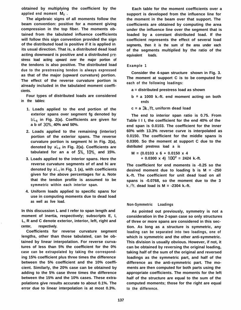
obtained by multiplying the coefficient by theapplied end moment M, .
The algebraic signs of all moments follow thebeam convention: positive for a moment givingcompression in the top fiber. The moments ob-tained from the tabulated influence coefficientswill follow this sign convention provided the signof the distributed load is positive if it is applied inits usual direction. That is, a distributed dead loadacting downward is positive and a distributed pre-stress load acting upward over the major portion ofthe tendons is also positive. The distributed loaddue to the prestressing tendon is always expressedas that of the major (upward curvature) portion.The effect of the reverse curvature portion isalready included in the tabulated moment coeffi-cients.
Four types of distributed loads are consideredin the tables:
1. Loads applied to the end portion of theexterior spans over segment fg denoted bybLE in Fig. 2(a). Coefficients are given fora b of 30%, 40% and 50%.
2. Loads applied to the remaining (interior)portion of the exterior spans. The reversecurvature portion is segment hi in Fig. 2(a),denoted by aL, in Fig. 2(a). Coefficients aretabulated for an a of 5%, lo%, and 15%.
3. Loads applied to the interior spans. Here thereverse curvature segments of ef and hi aredenoted by aL, in Fig. 1 (a), with coefficientsgiven for the above percentages for a. Notethat the tendon profile is assumed to besymmetric within each interior span.
4. Uniform loads applied to specific spans foruse in computing moments due to dead loadas well as live load.
,
In this discussion L and I refer to span length andmoment of inertia, respectively; subscripts E, I,L, R and C denote exterior, interior, left, right andcenter, respectively.
Coefficients for reverse curvature segmentlengths, other than those tabulated, can be ob-tained by linear interpolation. For reverse curva-tures of less than 5% the coefficient for the 0%case can be extrapolated by taking the correspond-ing 15% coefficient plus three times the differencebetween the 5% coefficient and the 10% coeffi-cient. Similarly, the 20% case can be obtained byadding to the 5% case three times the differencebetween the 15% and the 10% cases. These extra-polations give results accurate to about 0.1%. Theerror due to linear interpolation is at most 0.3%.
Each table for the moment coefficients over asupport is developed from the influence line forthe moment in the beam over that support. Thecoefficients are obtained by computing the areaunder the influence line over the segment that isloaded by a constant distributed load. If thecoefficient represents the effect of several loadsegments, then it is the sum of the area under eachof the segments multiplied by the ratio of theequivalent loads.
Example 1
Consider the 4-span structureThe moment at support C is toeach of the following loadings:
shown in Fig. 3.be computed for
a = distributed prestress load as shown
b = a 1000 k.-ft. end moment acting on bothends
c = a 3k./ft. uniform dead load
The end to interior span ratio is 0.75. FromTable I I I, the coefficient for the end 40% of theend span is 0.0103. The coefficient for the inner60% with 13.3% reverse curve is interpolated as0.0150. The coefficient for the middle spans is0.0300. So the moment at support C due to thedistributed prestress load a is
M = (0.0103 x 6 + 0.0150 x 4+ 0.0300 x 4) lOO* = 2424 k.-ft.
The coefficient for end moments is -0.25 so thedesired moment due to loading b is M = -250k.-ft. The coefficient for unit dead load on allspans is -0.0768, so the moment due to the 3k./ft. dead load is M = -2304 k.-ft.
Non-Symmetric Loadings
As pointed out previously, symmetry is not aconsideration in the 2-span case so only structuresof three or more spans are considered in this sec-tion. As long as a structure is symmetric, anyloading can be separated into two loadings, one ofwhich is symmetric and the other anti-symmetric.This division is usually obvious. However, if not, itcan be obtained by reversing the original loading,taking half of the sum of the original and reversedloadings as the symmetric part, and half of thedifference as the anti-symmetric part. The mo-ments are then computed for both parts using theappropriate coefficients. The moments for the lefthalf of the structure are equal to the sum of thecomputed moments; those for the right are equalto the difference.
137

Dead load3k/’
11111111111111111111lllllllllllllll 1111~
Prestrcss load
Fig 3 - 4 span structure for Example 1
Example 2
The moments at the supports of a beam of con-stant cross section with four equal spans are to becomputed. A typical non-symmetric equivalentprestress loading as produced when tensioning longbeams from one end is considered. End moments,as considered in this example, would appear only ifthe tendons are anchored away from the neutralaxis of the cross section, or if the beam is canti-levered. The complete loading diagram is shown in
Fig. 4a. Load diagrams (b), (c) and (d) show thereversed, the symmetric portion, and the anti-symmetric portion respectively. Note that only theleft half of the beam need be considered for thesethree loadings. Load diagram (b) was derived byfolding the right part of the structure about itscenterline. Load diagram (c) is half the sum of (a)and (b). Load diagram (d) can be computed eitheras the difference between (a) and (c) or as halfthe difference between (a) and (b). The moment atsupport 6 caused by the symmetric part of theloading is computed by using the coefficients inthe symmetric prestress portion of Table I I I.
MJi,, = (2.6 x 0.02103 + 2.0x 0.03493 + 2.0 x 0.0257)502+ 600 x (-0.2857) = 268.5 k.-ft.
The moment at support 8 due to the anti-sym-metric prestress is
M BA= (1.4x0.01840+ 1.0x 0.03056 + 0.5 x 0.04500)502+ 400 x (-0.2500) = 97k.-ft.
The moment at support C due to the symmetricload (Table IV) is
M cs = (-2.6 x 0.01051 - 2.0x 0.01746 + 2.0 x 0.07714)502+ 600 x 0.1429 = 316 k.-ft.
Fig 4 - 4-span structure with non-symmetric loading forExample 2
The moment at support C due to anti-symmetricprestress is zero.
M C A = 0
Finally, the moments at the three supports are
left: MB = MBS + MBA
= 365.5 k.-ft.
MC = M,, + McA = 316 k.-ft.
r i g h t : M, = MB, - MBA= 171.5 k.-ft.
MC = Mc, - McA = 316 k.-ft.
Spans With Different MomentsOf Inertia
Two cases of spans with different moments ofinertia may be analyzed using the tables. First,the cross section of the end spans may be differ-ent (e.g. the cross sections of the spans in a 2-spanbeam). Second, the center span cross section of a5-span beam may be different from the other twointerior spans.
If the cross sections of the end spans differ,replace the end span ratio computation LE/L, byLE I, /L, IE for selecting coefficients in the tables.Then multiply each distributed load applied tothe end spans by (IE /I, j2. For the 2-span case,the ratio is LL IR /L, I, and the multiplying factoris (IL /I, I2 applied to a distributed load on theleft span.
The center span section of a 5-span beam maybe different only to the extent that its stiffnessremains the same as for the other interior spans.That is Ic/Lc = 1,/L, where C refers to the centerspan and I refers to the other interior spans. Anydistributed loading applied to the center span mustthen be multiplied by (lc/l, j2.
138
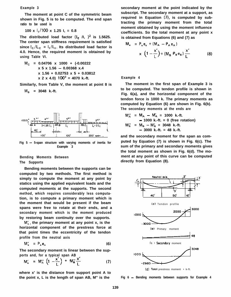
Example 3
The moment at point C of the symmetric beamshown in Fig. 5 is to be computed. The end spanratio to be used is
100 x I,/100 x 1.25 I, = 0.8
The distributed load factor (IE /I, I2 is 1.5625.The center span stiffness requirement is satisfiedsince Ic/Lc = 1,/L,. Its distributed load factor is4.0. Hence, the required moment is obtained byusing Table VI.
MC = 0.04706 x 1000 + (-0.00222x 5 x 1.56 - 0.00368 x.4x 1.56 + 0.02753 x 5 + 0.03812x 2 x 4.0) 1002 = 4070 k.-ft.
Similarly, from Table V, the moment at point 8 is
MEI = 3048 k.-ft.
Fig 5 - 5-span structure with varying moments of inertia forExample 3
Bending Moments BetweenThe Supports
Bending moments between the supports can becomputed by two methods. The first method issimply to compute the moment at any point bystatics using the applied equivalent loads and thecomputed moments at the supports. The secondmethod, which requires considerably less computa-tion, is to compute a primary moment which isthe moment that would be present if the beamspans were free to rotate at their ends, and asecondary moment which is the moment producedby restoring beam continuity over the supports.
ML, the primary moment at any point x, is thehorizontal component of the prestress force atthat point times the eccentricity of the tendonprofile from the neutral axis
W = Pxex (6)
The secondary moment is linear between the sup-ports and, for a typical span AB
M: = M;; (1 -F) + M;$
where x’ is the distance from support point A tothe point x, L is the length of span AB, M” is the
secondary moment at the point indicated by thesubscript. The secondary moment at a support, asrequired in Equation (7), is computed by sub-tracting the primary moment from the totalmoment obtained by using the moment influencecoefficients. So the total moment at any point xis obtained from Equations (6) and (7) as
MX = Pxex +(MA -P,e,)
x (l-5) +(Ms P,e.)s
Example 4
The moment in the first span of Example 3 isto be computed. The tendon profile is shown inFig. 6(a), and the horizontal component of thetendon force is 1000 k. The primary moments ascomputed by Equation (6) are shown in Fig. 6(b).The secondary moments at the ends are
M;; = MA - M;, = 1000 k.-ft.- 1000 k.-ft. = 0 (free rotation)
M;; = M, -ML = 3048 k.-ft.- 3000 k.-ft. = 48 k.-ft.
and the secondary moment for the span as com-puted by Equation (7) is shown in Fig. 6(c). Thesum of the primary and secondary moments givesthe total moment as shown in Fig. 6(d). The mo-ment at any point of this curve can be computeddirectly from Equation (8).
(01 Tendon pro f i le
(b) Primary moment
-48
Cc 1 Secondary moment
(d) Totol prestress moment - k-ft.
Fig 6 - Bending moments between supports for Example 4
139

Friction Losses
The equivalent load due to prestressing, as givenby Equations (1) to (5), is proportional to P, thehorizontal component of the force in the prestress-ing tendons. However, P is not constant along thebeam since it is reduced by friction losses along thetendons. A further variation of force is caused byanchor set as the load is transferred from thejacking device. Anchor set causes a reversal offriction forces in the end sections.
For short prestressing tendons the friction lossescan usually be neglected provided the total angularchange of the tendon profile is small. However,anchor set losses may be large. In this case botheffects may be accommodated by using a reducedconstant value of P for the length of the beam.
For long post-tensioned tendons, the frictionlosses cannot be neglected in the final analysis. AnACI Building Code (‘) formula gives the followingvalue for P at any section x in the beam:
PX = p ,-(KL + ~a)0 (9)
If the value of KL + plol is below 0.3, in accordancewith the ACI Code, Equation (9) may be replaced
byPO
P, =l+KL+/~cw
(10)
Equations (9) or (10) may also be used to com-pute friction losses through any segment of thebeam(*) in which case the reference section is thatend of the segment at which the tendon force P,has already been computed. For reasonable accur-acy in this case, Equation (10) should not be usedif the value of KL + ~CX for the segment is greaterthan about 0.1.
The computed tendon force at various sectionsalong the beam can now be plotted. If the slopeof the tendon is large, the horizontal componentcan be computed by multiplying the tendon forceby (1 - l/s*) where s is the tendon slope. A linearapproximation for the tendon force variation withdistance along the beam is sufficiently accuratefor most cases, and can be obtained by a straightline approximation of the plotted tendon force.
The loss of prestress force at the anchor sectiondue to anchor set is
AP, = 2dmL (11)
However, if the computed AP, is greater than 2 x
(PO - P,i” ), where P, is the jacking force andP,.,,i, is the lowest computed prestress force in thebeam - either at the non-jacking end for post-tensioning from one end, or near the midpoint forpost-tensioning from both ends - then
AP, = P, - P,i” +rAEAL
po - Pmin(12)
This value will be greater than the AP, computedby Equation (11). The prestress force plot can berevised to include the anchor set loss by notingthat the friction losses will be reversed in theregions affected. The prestress force at the anchorwill be P, - AP,, and will increase with distancefrom the anchor at a rate of r.
NOTATION
A
E
IEt I,
K
L
LE ,L,
AL
ME
M,, MA
= cross-sectional area of the pre-stressing tendons
= elastic modulus of the prestressingtendons
= moment of intertia of the crosssection in the span indicated
= friction loss factor related to length
= length of the segment over whichfriction loss is computed
= length of the span indicated
= tendon movement at the anchor dueto anchor set
= end moment due to eccentricity ofthe tendon over the exterior support
= bending moment at the point indi-cated
M’ and M” = primary and secondary bending
POAPo
pain
pxt PA
a
b
C
d
e
moments respectively
= jacking force
= loss of prestress force at the jackingend due to anchor set
= lowest prestress force consideringfriction losses
= horizontal component of the pre-stressing tendon force at the pointindicated
= ratio of the reverse curve length tothe span length
= ratio of the end segment length tothe span length in an exterior span
= drape of the tendon profile, highpoint to low point
= drape of the tendon profile in theend segment of an exterior span
= eccentricity of the tendon profileabove the neutral axis at the ex-terior support
140

e, ,e, ,etc. = eccentricity of the tendon profileabove the neutral axis at the pointindicated
r
S
w
= loss of prestress force per unitlength of beam
= slope of the tendon profile
= equivalent upward distributed loadover the major segment of the ten-don profile
wE
WR
X’
= equivalent upward distributed loadin the end segment of an exteriorspan
= equivalent downward distributedload over the reverse curvature seg-ment of the tendon profile
= distance from the end of a span to apoint x
a ! = angular change of the tendon profilein the segment over which frictionloss is computed
I-1 = friction loss factor related to angularchange of the tendon profile
Subscripts:
A and S designate anti-symmetric and symmetric,respectively.
x, A, B, C, etc. designate points along the beam.
L, R, E, I and C designate left, right, exterior,interior and center spans, respectively.
References
1. Moorman, Ft. B., “Equivalent Load Method for Analyz-ing Prestressed Concrete Structures,” Journal of theAmerican Concrete Institute, Vol. 23, No. 5, Jan. 1952,pp. 405416.
2. Norris, C. H., and Wilbur, J. B., “Elementary StructuralAnalysis,” McGraw-Hill, Inc., New York, 1960.
3. Parme, A. L. and Paris, G. H., “Analysis of ContinuousPrestressed Concrete Structures,” Proceedings of theFirst U.S. Conference on Prestressed Concrete, Cam-bridge, Mass., 1951, p. 195.
4. Bailey, D. M. and Ferguson, P. M., “Fixed-End MomentEquations for Continuous Prestressed Concrete Beams,”Journal of the Prestressed Concrete Institute, Vol. 11,No. 1, Feb. 1966, pp. 76-94.
5. Fiesenheiser, E. I., “Rapid Design of Continuous Pre-stressed Members,” Journal of the American ConcreteInsti tute, Vol . 25 , No. 8 , Apr i l 1954, pp. 669-676.
6. “ICES STRUDL-II, Engineering User’s Manual, Vol. 1,Frame Analysis,” Report R68-97, Department of CivilEngineering, Massachusetts Institute of Technology,Cambridge, Mass., Nov. 1968.
7. Lin, T. Y., “Design of Prestressed Concrete Structures,”John Wiley & Sons, Inc., New York, 1963.
8. “Building Code Requirements for Reinforced Concrete(ACI 318-63). American Concrete Institute, Detroit,Mich., 1963.
9. “Post-Tensioned Box Girder Bridges Design and Con-struction,” Concrete Reinforcing Steel Institute and Pre-stressed Concrete Institute, 1971.
141
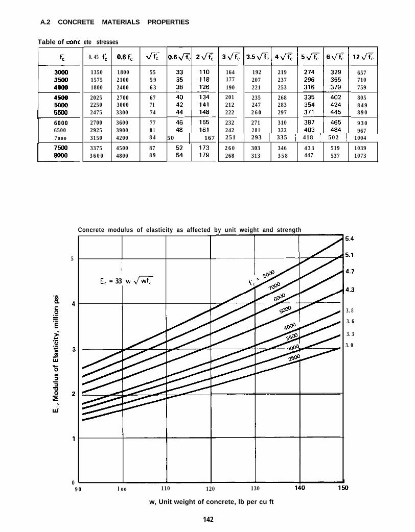
A.2 CONCRETE MATERIALS PROPERTIES
Table of coneI
I f ;:3ooo3500L4000
4500
6 0 0 065007ooo
ete stresses
0.45 f;: O.Sf; fi
1350 1800 551575 2100 591800 2400 63
2025 2700 672250 3000 712475 3300 74
2700 3600 772925 3900 813150 4200 84
3375 4500 873600 4800 89
50 ! 167 251 1 293 1 335 1 418 1 502 1 1004
164 192 219177 207 237190 221 253
201 235 268212 247 283222 260 297
232 271 310242 281 322
5
IE, = 33 w m
657710759
805849890
930967
260 303 346 433 519 1039268 313 358 447 537 1073
Concrete modulus of elasticity as affected by unit weight and strength
3.8
3.6
3.3
3.0
090 loo 110 120 130
w, Unit weight of concrete, lb per cu ft
142
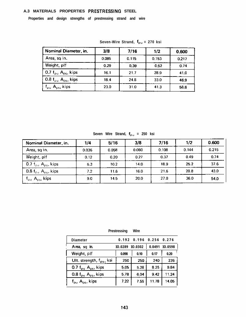
A.3 MATERIALS PROPERTIES PRESTRESSING STEEL
Properties and design strengths of prestressing strand and wire
Seven-Wire Strand, f,, = 270 ksi
Seven Wire Strand, f,, = 250 ksi
Prestressing Wire
Diameter 0 . 1 9 2 0 . 1 9 6 0 . 2 5 6 0 . 2 7 6
I A rea, sq in. IO.0289 IO.0302 1 0.0491 IO.0598 1
I Weight,plf 1 0.098 1 0.10 1 0.17 1 0.20 1

A.4 MATERIAL PROPERTIES PRESTRESSING STEEL -continued
Properties and design strengths of prestressing bars
Smooth Prestressing Bars, f,, = 145 ksi
Deformed Prestressing Bars
*The bar designated 5/8”S is made from a newly developed heat treated steel with an ultimate strength of230 ksi. Information on the properties of this steel in regard to stress corrosion, cracking, hydrogen em-brittlement, and relaxation is available from the supplier.
144

A.5 MATERIALS PROPERTIES REINFORCING STEELAreas and perimeters of reinforcing bar combinations
0 5-.
1 0 20 1 2 016 94
2 040 14031 110
3 =4 0 GO47
160 e.3126
4 0 80 180
i63 1 4 1
5 100 20079 1 5 7
1861 1 8217
=4
‘i3
1
1
1
11;
1:
l !
[
I
1
1E
t
I
1 :I
li
2C
;7
1 14
1E6
1s7
2 3
2a4
1 25
1 67
1
2 19
25
1 2 3 4 5 Areas. A lor A,I lfopl ~(1 I"Pertmeters. 10 (hottom) in
0 3 1 042 053 064 O 75 Columns bedded confa~n *ala for25 34 42 51 60
m_- bars of onerIfe I" groups of one 10 ten0 5 1 062 073 084 095 Columns headed contatn data41 50 58 67
35
1-1_ for bars of two s~zesw!lh from one 10 ftve
0 7 1 082 0 93 1 0 4 of each s,>e57 66 74 83 92 For harr of one 5118 10 sum of per~mterr0 9 1 102 1 13 1 2 4 1 3 573 a2 90 99 For hdrs of TWO s,zes 10 !-A-108
~111 122 13 3 1 4 4 155 whe h.4 D
3
n6441 f0 9561
1 2 681157100188 I
120
GE 75137 14 888 95I68 179
108 11 5I 99 2 10
1 2 7 134
1 2 4 1 4 466 77168 18890 100212 2 3 2
1 1 3 1 2 42 5 6 2 7 6
1 3 7 1 4 73 0 0 3 20160 171
1 8 4 2 1 5a4 982 4 4 2 7 5
1 1 2 126304 3 3 5139 1533 64 395
1 6 6 1 8 14 24 4 5 5
1 9 4 2 0 . 8
2 55 299102 1203 3 4 3 7 8134 15 14 13 457
1 6 5 1834 9 2 536197 2 1 45 7 1 6 15228 2 4 . 6
3 40 4 001 2 1 1424 40 500156 1 7 . 75 40 6 00
1 9 1 2 1 3640 7 0 0
2 2 7 2 4 87 4 0 800
262 284
443 5 221 4 0 1645 70 6 49180 204697 7 7 6
2 2 0 2 4 48 24 903
2 6 0 2 8 . 4951 1030
3 0 0 324
5 56 656158 1867 1 2 812
2 0 2 230868 968
2 4 6 2751024 1 1 2 429 1 3191180 12803 3 5 363
30 1 150 170 190 j210344 1 388 1 432 1 476 1 520
‘ 0 1198 1226 1254 1282i79 658 1 737 1 816 / 895
ioa 708 808 908 lOOR I12 22 3 254 28.635 I a35 I 935 I1035 1
'83 4 10 537 664 7 9 110 116 152 188 22439 1 566 1 693 1 820 1 947
7 29 3 329 365 401
1
1
1
1
1
1
1
1
1
1
1
2
1
1
21
21
0 9 1 1 2 242 56T5l 18269 832 1 1 2429G 11 12 7 1 30224 138331 3 625 1 165
123 1 6 749 67202 2 4 681 98281 3 2 51 2 130360 4 0 41 4 4 16 24 39 48376 193
1 G O 2 2057 78260 3 2092 1133G0 4 2028 1 4 9460 5 2063 184560 6 2099 220
206 28565 903 33 4 12
1 0 45514879192
1022 3 6!26280149
153702 1 3
972 7 3
1253 3 3
1 5 2J 93
1 8 0
2 1 18 4290116369
1 4 a4 48179527
21 1
280993801354 80170580
206680
2 4 1
364115491
1 5 56 18195745
2358 7 2275
4 56129612
1 7 47 68
2 1 8924261080306
145