Embed Size (px)
DESCRIPTION
RCC42 Post Tensioned Analysis & Design
Citation preview
Project Spreadsheets to BS 8110 REINFORCED CONCRETE COUNCIL
Client Advisory Group Made by Date Page
Location Level 2 - Beam on Grid 7 RMW 17-Apr-2023 66
POST-TENSIONED ANALYSIS & DESIGN to BS 8110:1997 Checked Revision Job No
chg - R68
POST-TENSIONED ANALYSIS & DESIGN to BS 8110:1997 - GENERAL DATA
LOAD COMBINATIONS NOTESSLS 1 Initial prestress + OW + construction load on all spans INPUT IS UNDERLINED.
INITIAL SLS 2 Initial prestress + OW + construction load on odd spans
SLS 3 Initial prestress + OW + construction load on even spans
SLS 4 Final prestress + dead + imposed load on all spansFINAL SLS 5 Final prestress + dead + imposed load on odd spans
SLS 6 Final prestress + dead + imposed load on even spans
ULS 1 Final prestress + factored dead and imposed load on all spansULTIMATE ULS 2 Final prestress + factored dead + factored imposed load on odd spans
ULS 3 Final prestress + factored dead + factored imposed load on even spans
DEFLECTION SLS 7 Err:504
LOAD FACTORS min max VIBRATIONDEAD 1 1.4 Limiting reponse factor = 8
IMPOSED 0 1.6
OPTIONS Stressing Ends B (L, R, B) Prestress system U (U, B) Assume 20% max redistributionJacking F/strength 0.7 BS 8110 Class 3 (Clause 4.1.3) .
Slab or beam B (B or S) miting crack width 0.2 mm .
In slabs, nominal top bonded reinforcement in span?Y(Y or N; use Y for dissimilar spans)Slab type S(S)olid, (R)ibbed or (W)affle, supported by beam 5%
MATERIALS CONCRETE fcu = 40 Ec28 = 28 13.20 5.00 unmodifiedAt days 4.80 fci = 25.04 Eci = 21.72 10.02 3.20 unmodified
Cement content 330 W/C ratio 0.55 OPC or RHPC ? OPC .
Ave ambient during curing = 15ºC Longterm R/H % 50 1.50
STRAND fpu = 1860 100 µ = 0.140 K = 0.0010Ep = 195 Rel % = 2 Draw in= 6 Depth to strand centre = 40
REBAR fy = 460 COVERS Top Bottom Sides1.05 to links 25 25 25
LOADING SEQUENCE Permanent loads for Ø assessment 30% of Imposed is permanentLoad @ Age fcut Et Ø Ec
kN/m² days N/mm² kN/mm² Creep kN/mm²
Own weight 13.81 4.80 25.04 21.72 3.64 4.68Applied dead 42.00 60 43.50 29.47 2.14 9.39
Quasi-Permanent Imposed 9.60 - = -COMBINED 65.41 - - 26.76 2.45 7.75
NOTES on MATERIALS
BRITISH LOW RELAXATION STRAND
Type Dia Area Breaking Weight RELAXATION at 0.7fpuStandard 15.2 139 1670 1.090 Ambient ºC 20 40 60 80 100
12.5 93 1770 0.730 Relaxation 1.8 3.5 5.1 7.5 10.7Super 15.7 150 1770 1.180
12.9 100 1860 0.785Compact 15.2 165 1820 1.295
12.7 112 1860 0.890
Originated from RCC42.xls on CD © 1999 RCC
FRAMES ARE ASSUMED TO BE BRACED
Damping, z (2% to 8%)
sc = st =sic = sit =
gm =
Ap, mm² =
gm =
Project Spreadsheets to BS 8110 REINFORCED CONCRETE COUNCIL
Client Advisory Group Made by Date Page
Location Level 2 - Beam on Grid 7 RMW 17-Apr-2023 70
POST-TENSIONED ANALYSIS & DESIGN to BS 8110:1997 Checked Revision Job No
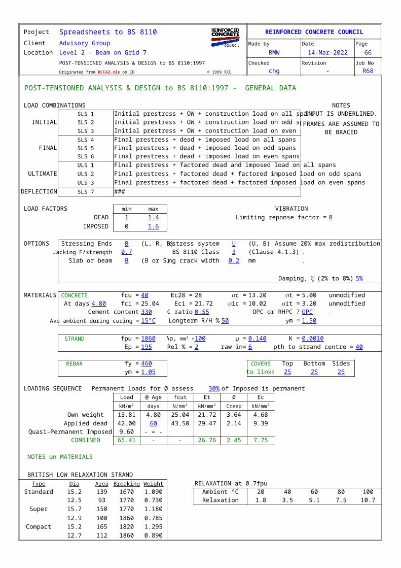
Originated from RCC42.xls on CD © 1999 RCC chg - R68SUMMARY iv
Link Ø = 10Span 1 Span 2 Span 3
Left Right Left Right Left RightV 636.0 882.1 919.3 677.9 0.0 0.0
cracked? N Y Y N N NVc 1396.8 736.8 757.3 1396.8 0.0 0.0
No of legs 8 8 8 8 8 8Link spacing 375 375 375 375 0 0
Span 1 Span 2 Span 3
Response factor 0.62 0.70 0.00OK OK OK
Span 1 = 9.6mm < 48 OK Span 2 = 15.8mm < 50 OK- -
SUPPORT REACTIONS Supt 1 Supt 2 Supt 3 Supt 4
ULS 4 650.5 1840.2 677.9 0.0 kN
ULS 5 655.4 1362.1 232.0 0.0 kN
ULS 6 199.1 1409.3 677.9 0.0 kN
DEAD 274.4 803.8 289.0 0.0 kN
IMPOSED 147.0 484.4 152.6 0.0 kN
COLUMN MOMENTS Supt 1 Supt 2 Supt 3 Supt 4
ULS 4 Above 0.00 0.00 0.00 0.00 kNm
Below 0.00 0.00 0.00 0.00 kNm
ULS 5 Above 0.00 0.00 0.00 0.00 kNm
Below 0.00 0.00 0.00 0.00 kNm
ULS 6 Above 0.00 0.00 0.00 0.00 kNm
Below 0.00 0.00 0.00 0.00 kNm
(e) SHEAR
(f) VIBRATION
(g) DEFLECTION
-1500
-1000
-500
0
500
1000
1500
938.7
-677.9
650.5
-901.4
ULS SHEAR ENVELOPE
-20
-15
-10
-5
0
5
10
15
-9.43
-15.41
7.90 9.20
MAX DEFLECTIONS
Transfer Final Col centres
Project Spreadsheets to BS 8110 REINFORCED CONCRETE COUNCIL
Client Advisory Group Made by Date Page
Location Level 2 - Beam on Grid 7 RMW 17-Apr-23 71POST-TENSIONED ANALYSIS & DESIGN to BS 8110:1997 Checked Revision Job No
Originated from RCC42.xls on CD © 1999 RCC chg - R68
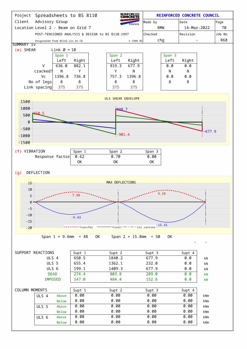
TYPICAL CALCULATION BS 8110
for Span 1 at 3.60 m from C/L of LH support Reference
Class 3 Tee section, h = 525 mm, bw = 1800 mm hf = 200 mm, bf =3000 mm.
Ac = 1185000mm2, Z top = 120.0E6 mm³, and Z bottom = 93.3E6 mm³
Tendons are unbonded, Ap = 100mm2, fpu = 1,860 N/mm2 and 75.9 mm from soffite
There are 24 tendons, jacked to 1,302 N/mm² or 70.0% fpu
Prestress losses at this section are -2,500.7 kN at transfer and -2,237.1 kN longterm
4.3.5
M = 394.4 kNm hogging, and prestressing force = 2,761.1 kN
Max compression (bottom) = M/Z + P/A = 394.4E3 / 93.3 + 2,761.1 / 1185 = 6.56 N/mm²
< 10.02 N/mm² allowed
Max tension (bottom) = M/Z - P/A = -158.3E3 / 93.3 - 2,761.1 / 1185 = 0.96 N/mm²
< 3.00 N/mm² allowed
4.3.4
M = 400.5 kNm sagging, and prestressing force = 2,497.5 kNMax compression (top) = 400.46E6 / 120.0E6 + 2,497.5E3 / 1185E3 = 5.44 N/mm²
< 13.33 N/mm² allowed
Max tension (bottom) = 400.46 / 93.3 - 2,497.5 / 1185 = 2.18 N/mm²
< 4.73 N/mm² allowed
4.3.7
M = 1,382.7 kNm sagging, and prestressing force = 2,497.5 kN
fpe = 1000 x 2,497.5 / 24 / 100 = 1,040.6 N/mm²Reinforcement d = 480 mm
Rp = 1860 x 100 x 24 / 40 / 3000 / (525 - 75.86) = 0.083
fpe/fpu = 1,040.6 / 1860 x 1.05 = 0.587
Lte = 12,250 mm
fpb (unbonded)
= 1,040.6 + 7000 x (525 - 75.86) / 12,250 (1 - 1.7 x 0.083) = 1,261.1 N/mm² Eq 52
Tendon force = 1,261.1 x 24 x 100 / 1000 = 3,026.7 kN
Rebar force = 460 / 1.05 x 6,283 / 1000 = 2,752.6 kN
Total tensile force = 3,026.7 + 2,752.6 = 5,779.4 kN
Compression block depth, dn = 1000 / 5,779.4 / 0.45 / 40 / 3000 = 107.03 mm
MOR = (3,026.7 ( 525 - 75.9 - 107.03 / 2) + 2,752.6 x (480 - 107.03 / 2)) / 1000 Eq 51
= 2,371.4 kNm > 1,382.7 ok
(b) Stresses at transfer
(c) Stresses in service
(d) MOR at ultimate limit state
Project Spreadsheets to BS 8110 REINFORCED CONCRETE COUNCIL
Client Advisory Group Made by Date Page
Location Level 2 - Beam on Grid 7 RMW 17-Apr-2023 80
POST-TENSIONED ANALYSIS & DESIGN TO BS 8110 Checked Revision Job No
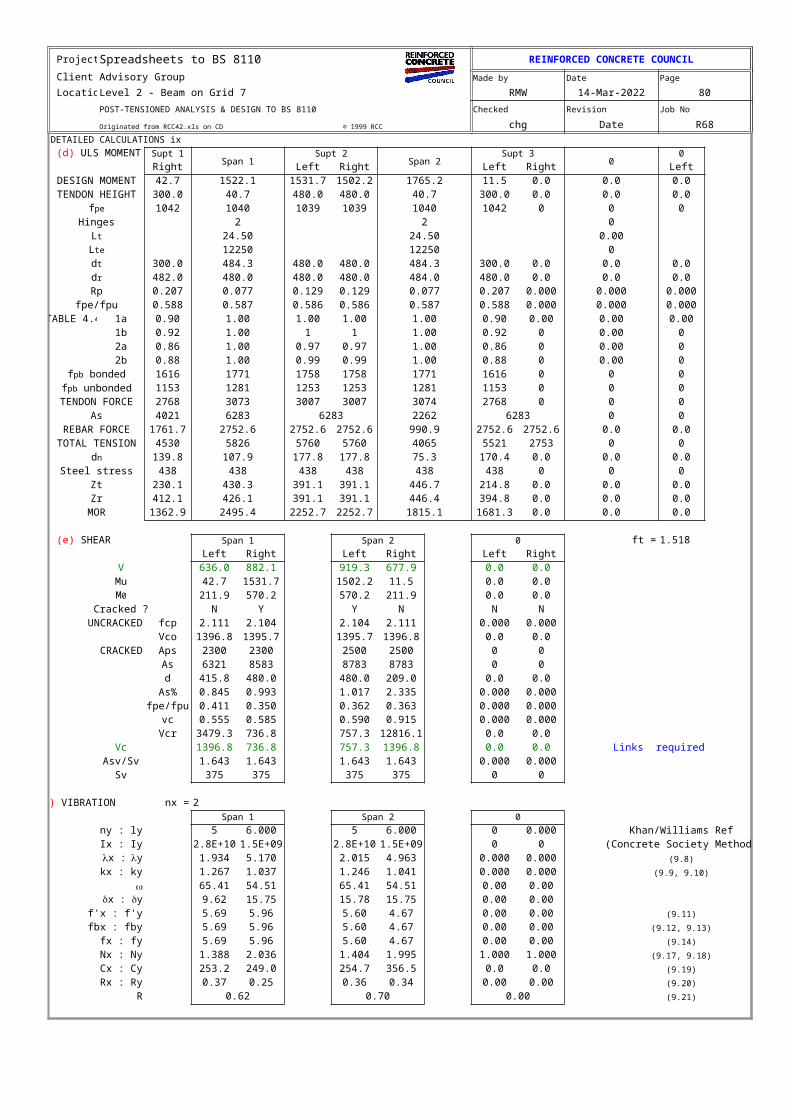
Originated from RCC42.xls on CD © 1999 RCC chg Date R68DETAILED CALCULATIONS ix
Supt 1Span 1
Supt 2Span 2
Supt 30
0
Right Left Right Left Right LeftDESIGN MOMENT 42.7 1522.1 1531.7 1502.2 1765.2 11.5 0.0 0.0 0.0TENDON HEIGHT 300.0 40.7 480.0 480.0 40.7 300.0 0.0 0.0 0.0
1042 1040 1039 1039 1040 1042 0 0 0Hinges 2 2 0
24.50 24.50 0.0012250 12250 0
300.0 484.3 480.0 480.0 484.3 300.0 0.0 0.0 0.0482.0 480.0 480.0 480.0 484.0 480.0 0.0 0.0 0.0
Rp 0.207 0.077 0.129 0.129 0.077 0.207 0.000 0.000 0.000fpe/fpu 0.588 0.587 0.586 0.586 0.587 0.588 0.000 0.000 0.000
TABLE 4.4 1a 0.90 1.00 1.00 1.00 1.00 0.90 0.00 0.00 0.001b 0.92 1.00 1 1 1.00 0.92 0 0.00 02a 0.86 1.00 0.97 0.97 1.00 0.86 0 0.00 02b 0.88 1.00 0.99 0.99 1.00 0.88 0 0.00 0
1616 1771 1758 1758 1771 1616 0 0 01153 1281 1253 1253 1281 1153 0 0 0
TENDON FORCE 2768 3073 3007 3007 3074 2768 0 0 0As 4021 6283 6283 2262 6283 0 0
REBAR FORCE 1761.7 2752.6 2752.6 2752.6 990.9 2752.6 2752.6 0.0 0.0TOTAL TENSION 4530 5826 5760 5760 4065 5521 2753 0 0
139.8 107.9 177.8 177.8 75.3 170.4 0.0 0.0 0.0Steel stress 438 438 438 438 438 438 0 0 0
Zt 230.1 430.3 391.1 391.1 446.7 214.8 0.0 0.0 0.0Zr 412.1 426.1 391.1 391.1 446.4 394.8 0.0 0.0 0.0
MOR 1362.9 2495.4 2252.7 2252.7 1815.1 1681.3 0.0 0.0 0.0
Span 1 Span 2 0 ft = 1.518Left Right Left Right Left Right
V 636.0 882.1 919.3 677.9 0.0 0.0Mu 42.7 1531.7 1502.2 11.5 0.0 0.0
211.9 570.2 570.2 211.9 0.0 0.0Cracked ? N Y Y N N N
UNCRACKED fcp 2.111 2.104 2.104 2.111 0.000 0.000Vco 1396.8 1395.7 1395.7 1396.8 0.0 0.0
CRACKED Aps 2300 2300 2500 2500 0 0As 6321 8583 8783 8783 0 0d 415.8 480.0 480.0 209.0 0.0 0.0
As% 0.845 0.993 1.017 2.335 0.000 0.000fpe/fpu 0.411 0.350 0.362 0.363 0.000 0.000
vc 0.555 0.585 0.590 0.915 0.000 0.000Vcr 3479.3 736.8 757.3 12816.1 0.0 0.0
Vc 1396.8 736.8 757.3 1396.8 0.0 0.0 Links requiredAsv/Sv 1.643 1.643 1.643 1.643 0.000 0.000
Sv 375 375 375 375 0 0
nx = 2Span 1 Span 2 0
ny : ly 5 6.000 5 6.000 0 0.000 Khan/Williams RefIx : Iy 2.8E+10 1.5E+09 2.8E+10 1.5E+09 0 0 (Concrete Society Method)
1.934 5.170 2.015 4.963 0.000 0.000 (9.8)
kx : ky 1.267 1.037 1.246 1.041 0.000 0.000 (9.9, 9.10)
w 65.41 54.51 65.41 54.51 0.00 0.009.62 15.75 15.78 15.75 0.00 0.00
f'x : f'y 5.69 5.96 5.60 4.67 0.00 0.00 (9.11)
fbx : fby 5.69 5.96 5.60 4.67 0.00 0.00 (9.12, 9.13)
fx : fy 5.69 5.96 5.60 4.67 0.00 0.00 (9.14)
Nx : Ny 1.388 2.036 1.404 1.995 1.000 1.000 (9.17, 9.18)
Cx : Cy 253.2 249.0 254.7 356.5 0.0 0.0 (9.19)
Rx : Ry 0.37 0.25 0.36 0.34 0.00 0.00 (9.20)
R 0.62 0.70 0.00 (9.21)
(d) ULS MOMENT CHECKS
fpe
Lt
Lte
dt
dr
fpb bondedfpb unbonded
dn
(e) SHEAR
M0
(f) VIBRATION
lx : ly
dx : dy
Project Spreadsheets to BS 8110 REINFORCED CONCRETE COUNCIL
Client Advisory Group Made by Date Page
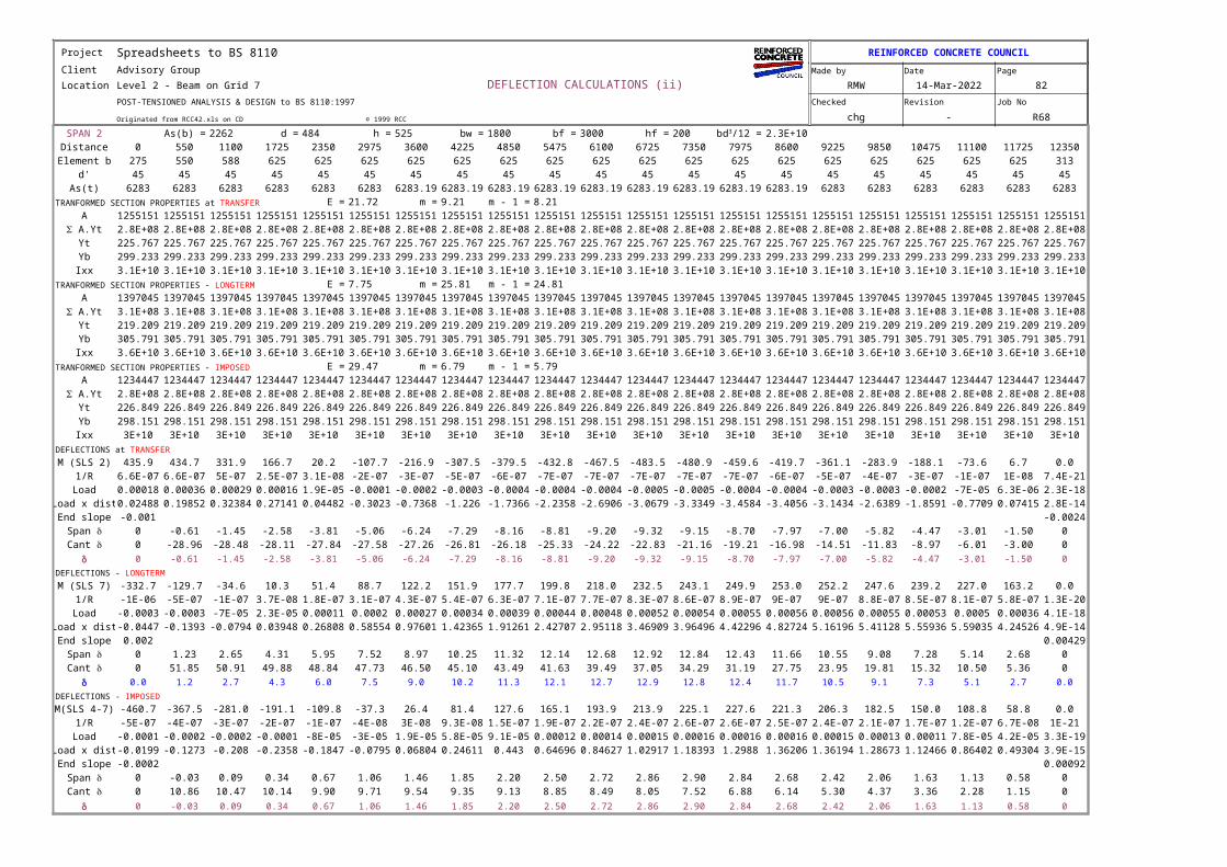
Location Level 2 - Beam on Grid 7 DEFLECTION CALCULATIONS (ii) RMW 17-Apr-2023 82
POST-TENSIONED ANALYSIS & DESIGN to BS 8110:1997 Checked Revision Job No
Originated from RCC42.xls on CD © 1999 RCC chg - R68
SPAN 2 As(b) = 2262 d = 484 h = 525 bw = 1800 bf = 3000 hf = 200 2.3E+10Distance 0 550 1100 1725 2350 2975 3600 4225 4850 5475 6100 6725 7350 7975 8600 9225 9850 10475 11100 11725 12350
Element b 275 550 588 625 625 625 625 625 625 625 625 625 625 625 625 625 625 625 625 625 313d' 45 45 45 45 45 45 45 45 45 45 45 45 45 45 45 45 45 45 45 45 45
As(t) 6283 6283 6283 6283 6283 6283 6283.19 6283.19 6283.19 6283.19 6283.19 6283.19 6283.19 6283.19 6283.19 6283 6283 6283 6283 6283 6283E = 21.72 m = 9.21 m - 1 = 8.21
A 1255151 1255151 1255151 1255151 1255151 1255151 1255151 1255151 1255151 1255151 1255151 1255151 1255151 1255151 1255151 1255151 1255151 1255151 1255151 1255151 12551512.8E+08 2.8E+08 2.8E+08 2.8E+08 2.8E+08 2.8E+08 2.8E+08 2.8E+08 2.8E+08 2.8E+08 2.8E+08 2.8E+08 2.8E+08 2.8E+08 2.8E+08 2.8E+08 2.8E+08 2.8E+08 2.8E+08 2.8E+08 2.8E+08
Yt 225.767 225.767 225.767 225.767 225.767 225.767 225.767 225.767 225.767 225.767 225.767 225.767 225.767 225.767 225.767 225.767 225.767 225.767 225.767 225.767 225.767Yb 299.233 299.233 299.233 299.233 299.233 299.233 299.233 299.233 299.233 299.233 299.233 299.233 299.233 299.233 299.233 299.233 299.233 299.233 299.233 299.233 299.233Ixx 3.1E+10 3.1E+10 3.1E+10 3.1E+10 3.1E+10 3.1E+10 3.1E+10 3.1E+10 3.1E+10 3.1E+10 3.1E+10 3.1E+10 3.1E+10 3.1E+10 3.1E+10 3.1E+10 3.1E+10 3.1E+10 3.1E+10 3.1E+10 3.1E+10
E = 7.75 m = 25.81 m - 1 = 24.81A 1397045 1397045 1397045 1397045 1397045 1397045 1397045 1397045 1397045 1397045 1397045 1397045 1397045 1397045 1397045 1397045 1397045 1397045 1397045 1397045 1397045
3.1E+08 3.1E+08 3.1E+08 3.1E+08 3.1E+08 3.1E+08 3.1E+08 3.1E+08 3.1E+08 3.1E+08 3.1E+08 3.1E+08 3.1E+08 3.1E+08 3.1E+08 3.1E+08 3.1E+08 3.1E+08 3.1E+08 3.1E+08 3.1E+08Yt 219.209 219.209 219.209 219.209 219.209 219.209 219.209 219.209 219.209 219.209 219.209 219.209 219.209 219.209 219.209 219.209 219.209 219.209 219.209 219.209 219.209Yb 305.791 305.791 305.791 305.791 305.791 305.791 305.791 305.791 305.791 305.791 305.791 305.791 305.791 305.791 305.791 305.791 305.791 305.791 305.791 305.791 305.791Ixx 3.6E+10 3.6E+10 3.6E+10 3.6E+10 3.6E+10 3.6E+10 3.6E+10 3.6E+10 3.6E+10 3.6E+10 3.6E+10 3.6E+10 3.6E+10 3.6E+10 3.6E+10 3.6E+10 3.6E+10 3.6E+10 3.6E+10 3.6E+10 3.6E+10
E = 29.47 m = 6.79 m - 1 = 5.79A 1234447 1234447 1234447 1234447 1234447 1234447 1234447 1234447 1234447 1234447 1234447 1234447 1234447 1234447 1234447 1234447 1234447 1234447 1234447 1234447 1234447
2.8E+08 2.8E+08 2.8E+08 2.8E+08 2.8E+08 2.8E+08 2.8E+08 2.8E+08 2.8E+08 2.8E+08 2.8E+08 2.8E+08 2.8E+08 2.8E+08 2.8E+08 2.8E+08 2.8E+08 2.8E+08 2.8E+08 2.8E+08 2.8E+08Yt 226.849 226.849 226.849 226.849 226.849 226.849 226.849 226.849 226.849 226.849 226.849 226.849 226.849 226.849 226.849 226.849 226.849 226.849 226.849 226.849 226.849Yb 298.151 298.151 298.151 298.151 298.151 298.151 298.151 298.151 298.151 298.151 298.151 298.151 298.151 298.151 298.151 298.151 298.151 298.151 298.151 298.151 298.151Ixx 3E+10 3E+10 3E+10 3E+10 3E+10 3E+10 3E+10 3E+10 3E+10 3E+10 3E+10 3E+10 3E+10 3E+10 3E+10 3E+10 3E+10 3E+10 3E+10 3E+10 3E+10
M (SLS 2) 435.9 434.7 331.9 166.7 20.2 -107.7 -216.9 -307.5 -379.5 -432.8 -467.5 -483.5 -480.9 -459.6 -419.7 -361.1 -283.9 -188.1 -73.6 6.7 0.01/R 6.58E-07 6.56E-07 5E-07 2.52E-07 3.05E-08 -1.6E-07 -3.3E-07 -4.6E-07 -5.7E-07 -6.5E-07 -7.1E-07 -7.3E-07 -7.3E-07 -6.9E-07 -6.3E-07 -5.5E-07 -4.3E-07 -2.8E-07 -1.1E-07 1E-08 7.42E-21
Load 0.00018 0.00036 0.00029 0.00016 1.91E-05 -0.0001 -0.0002 -0.00029 -0.00036 -0.00041 -0.00044 -0.00046 -0.00045 -0.00043 -0.0004 -0.00034 -0.00027 -0.00018 -6.9E-05 6.32E-06 2.32E-18Load x dist 0.02488 0.19852 0.32384 0.27141 0.04482 -0.30226 -0.73684 -1.22596 -1.73661 -2.23581 -2.69058 -3.06793 -3.33488 -3.45844 -3.40562 -3.14344 -2.63892 -1.85906 -0.77089 0.07415 2.76E-14End slope -0.00098 -0.0024
0 -0.61 -1.45 -2.58 -3.81 -5.06 -6.24 -7.29 -8.16 -8.81 -9.20 -9.32 -9.15 -8.70 -7.97 -7.00 -5.82 -4.47 -3.01 -1.50 00 -28.96 -28.48 -28.11 -27.84 -27.58 -27.26 -26.81 -26.18 -25.33 -24.22 -22.83 -21.16 -19.21 -16.98 -14.51 -11.83 -8.97 -6.01 -3.00 0
d 0 -0.61 -1.45 -2.58 -3.81 -5.06 -6.24 -7.29 -8.16 -8.81 -9.20 -9.32 -9.15 -8.70 -7.97 -7.00 -5.82 -4.47 -3.01 -1.50 0
M (SLS 7) -332.7 -129.7 -34.6 10.3 51.4 88.7 122.2 151.9 177.7 199.8 218.0 232.5 243.1 249.9 253.0 252.2 247.6 239.2 227.0 163.2 0.01/R -1.2E-06 -4.6E-07 -1.2E-07 3.66E-08 1.83E-07 3.15E-07 4.34E-07 5.39E-07 6.31E-07 7.09E-07 7.74E-07 8.25E-07 8.63E-07 8.87E-07 9E-07 9E-07 8.79E-07 8.49E-07 8.06E-07 5.79E-07 1.31E-20
Load -0.00032 -0.00025 -7.2E-05 2.29E-05 0.00011 0.0002 0.00027 0.00034 0.00039 0.00044 0.00048 0.00052 0.00054 0.00055 0.00056 0.00056 0.00055 0.00053 0.0005 0.00036 4.1E-18Load x dist -0.04467 -0.13932 -0.07936 0.03948 0.26808 0.58554 0.97601 1.42365 1.91261 2.42707 2.95118 3.46909 3.96496 4.42296 4.82724 5.16196 5.41128 5.55936 5.59035 4.24526 4.87E-14End slope 0.002 0.00429
0 1.23 2.65 4.31 5.95 7.52 8.97 10.25 11.32 12.14 12.68 12.92 12.84 12.43 11.66 10.55 9.08 7.28 5.14 2.68 00 51.85 50.91 49.88 48.84 47.73 46.50 45.10 43.49 41.63 39.49 37.05 34.29 31.19 27.75 23.95 19.81 15.32 10.50 5.36 0
d 0.0 1.2 2.7 4.3 6.0 7.5 9.0 10.2 11.3 12.1 12.7 12.9 12.8 12.4 11.7 10.5 9.1 7.3 5.1 2.7 0.0
M(SLS 4-7) -460.7 -367.5 -281.0 -191.1 -109.8 -37.3 26.4 81.4 127.6 165.1 193.9 213.9 225.1 227.6 221.3 206.3 182.5 150.0 108.8 58.8 0.01/R -5.3E-07 -4.2E-07 -3.2E-07 -2.2E-07 -1.3E-07 -4.3E-08 3E-08 9.32E-08 1.46E-07 1.89E-07 2.22E-07 2.45E-07 2.58E-07 2.61E-07 2.53E-07 2.36E-07 2.09E-07 1.72E-07 1.25E-07 6.73E-08 1E-21
Load -0.00015 -0.00023 -0.00019 -0.00014 -7.9E-05 -2.7E-05 1.89E-05 5.83E-05 9.13E-05 0.00012 0.00014 0.00015 0.00016 0.00016 0.00016 0.00015 0.00013 0.00011 7.78E-05 4.21E-05 3.25E-19Load x dist -0.01994 -0.12728 -0.20796 -0.23584 -0.18468 -0.07947 0.06804 0.24611 0.443 0.64696 0.84627 1.02917 1.18393 1.2988 1.36206 1.36194 1.28673 1.12466 0.86402 0.49304 3.87E-15End slope -0.00016 0.00092
0 -0.03 0.09 0.34 0.67 1.06 1.46 1.85 2.20 2.50 2.72 2.86 2.90 2.84 2.68 2.42 2.06 1.63 1.13 0.58 00 10.86 10.47 10.14 9.90 9.71 9.54 9.35 9.13 8.85 8.49 8.05 7.52 6.88 6.14 5.30 4.37 3.36 2.28 1.15 0
d 0 -0.03 0.09 0.34 0.67 1.06 1.46 1.85 2.20 2.50 2.72 2.86 2.90 2.84 2.68 2.42 2.06 1.63 1.13 0.58 0
bd3/12 =
TRANFORMED SECTION PROPERTIES at TRANSFER
S A.Yt
TRANFORMED SECTION PROPERTIES - LONGTERM
S A.Yt
TRANFORMED SECTION PROPERTIES - IMPOSED
S A.Yt
DEFLECTIONS at TRANSFER
Span dCant d
DEFLECTIONS - LONGTERM
Span dCant d
DEFLECTIONS - IMPOSED
Span dCant d
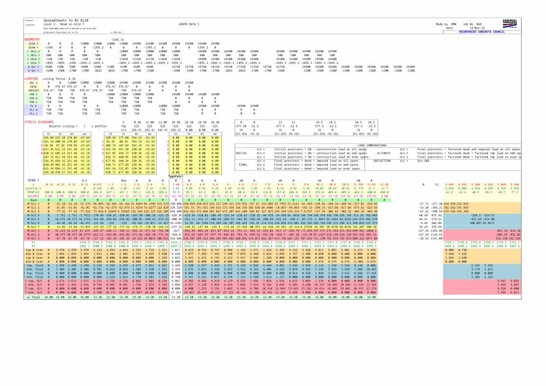
Project Spreadsheets to BS 8110 Location Level 2 - Beam on Grid 7 GRAPH DATA I Made by RMW Job No R68
POST-TENSIONED ANALYSIS & DESIGN to BS 8110:1997 Date 17-Apr-23Originated from RCC42.xls on CD © 1999 RCC REINFORCED CONCRETE COUNCIL
GEOMETRY -1395.15BEAM X 0 0 0 12000 12000 12000 12000 24500 24500 24500 24500 24500 24500 24500BEAM Y -1395 0 0 0 -1395.15 0 0 0 -1395.15 0 0 0 -1395.15 0
C SECa X 0 0 0 0 0 12000 12000 12000 12000 12000 24500 24500 24500 24500 24500 24500 24500 24500 24500 24500C SECa Y 500 500 500 500 500 500 500 500 500 500 500 500 500 500 500 500 500 500 500 500C SECb X -150 150 150 -150 -150 11850 12150 12150 11850 11850 24500 24500 24500 24500 24500 24500 24500 24500 24500 24500C SECb Y -1895 -1895 -2495.1 -2495.15 -1895.15 -1895.15 -1895.15 -2495.15 -2495.15 -1895.15 -1895.15 -1895.15 -1895.15 -1895.15 -1895.15 -1895.15 -1895.15 -1895.15 -1895.15 -1895.15B SEC X 4500 7500 7500 6900 6900 5100 5100 4500 4500 16750 19750 19750 19150 19150 17350 17350 16750 16750 24500 24500 24500 24500 24500 24500 24500 24500 24500B SEC Y -1500 -1500 -1700 -1700 -2025 -2025 -1700 -1700 -1500 -1500 -1500 -1700 -1700 -2025 -2025 -1700 -1700 -1500 -1500 -1500 -1500 -1500 -1500 -1500 -1500 -1500 -1500
LOADING scaling factor 8.54UDL X 0 0 12000 12000 12000 12000 24500 24500 24500 24500 24500 24500DEAD 0 476.67 476.67 0 0 476.67 476.67 0 0 0 0 0
IMPOSED 476.67 750 750 476.67 476.67 750 750 476.67 0 0 0 0PUD X 0 0 0 0 12000 12000 12000 12000 24500 24500 24500 24500PUD D 750 750 750 750 750 750 750 750 0 0 0 0PUD L 750 750 750 750 750 750 750 750 0 0 0 0PL X 0 0 0 0 12000 12000 12000 12000 24500 24500 24500 24500PLs D 750 750 750 750 750 750 750 750 0 0 0 0PLs L 750 750 750 750 750 750 750 750 0 0 0 0
STRESS DIAGRAMS X -0.30 12.00 12.00 24.50 24.50 24.50 24.50 0 0 12 12 24.5 24.5 24.5 24.5Balance scaling = 1 x profile Top 525 525 525 525 525 525 525 577.50 -52.5 577.5 -52.5 577.5 -52.5 577.5 -52.5
n/a 295.41 295.41 295.41 295.41 0.00 0.00 0.00 16 0 16 0 16 0 16 0Vl Vr W1 we Vl Vr W1 we Vl Vr W1 we 351.835 -93.16 351.835 -93.1645 351.835 -93.1645 351.835 -93.1645
166.09 215.58 278.03 -67.64 220.58 177.00 354.19 -61.54 0.00 0.00 0.00 0.00S 181.12 200.56 278.03 -67.64 S 92.25 80.33 354.19 -61.54 S 0.00 0.00 0.00 0.00P 68.38 97.29 278.03 -67.64 P 209.73 187.84 354.19 -61.54 P 0.00 0.00 0.00 0.00 LOAD COMBINATIONSA 421.45 632.23 251.48 -61.18 A 655.99 441.58 320.36 -55.66 A 0.00 0.00 0.00 0.00 SLS 1 Initial prestress + OW + construction load on all spans ULS 1 Final prestress + factored dead and imposed load on all spansN 448.15 605.52 251.48 -61.18 N 427.85 269.73 320.36 -55.66 N 0.00 0.00 0.00 0.00 INITIAL SLS 2 Initial prestress + OW + construction load on odd spans ULTIMATE ULS 2 Final prestress + factored dead + factored imp load on odd spans
247.74 421.94 251.48 -61.18 636.72 460.86 320.36 -55.66 0.00 0.00 0.00 0.00 SLS 3 Initial prestress + OW + construction load on even spans ULS 3 Final prestress + factored dead + factored imp load on even spans1 326.55 458.32 251.48 -61.18 2 477.01 340.56 320.36 -55.66 3 0.00 0.00 0.00 0.00 SLS 4 Final prestress + dead + imposed load on all spans DEFLECTION SLS 7 Err:504
650.49 901.45 251.48 -61.18 938.71 677.89 320.36 -55.66 0.00 0.00 0.00 0.00 FINAL SLS 5 Final prestress + dead + imposed load on odd spans655.44 896.51 251.48 -61.18 465.56 232.01 320.36 -55.66 0.00 0.00 0.00 0.00 SLS 6 Final prestress + dead + imposed load on even spans199.10 470.57 251.48 -61.18 938.71 677.89 320.36 -55.66 0.00 0.00 0.00 0.00
TypiCalc!
SPAN 1 0.6 Btm 0 0 0 0 0 0 0 20 0 20 0 20 0 20 0X -0.15 -0.15 0.15 0.15 0.675 1.2 1.2 1.8 2.4 3 3.60 4.2 4.8 5.4 6 6.6 7.2 7.8 8.4 9 9.6 10.2 10.8 10.8 11.325 11.85 11.85 0 12 5.694 4.953 5.104 4.439 5.068 3.568
profile X 0 0.525 1.05 1.05 1.65 2.25 2.85 3.45 4.05 4.65 5.25 5.85 6.45 7.05 7.65 8.25 8.85 9.45 10.05 10.65 10.65 11.175 11.7 11.7 5.544 4.803 4.954 4.289 4.918 3.418PROFILE 300.0 300.0 300.0 300.0 286.8 247.1 247.1 191.1 143.8 105.4 75.9 55.1 43.2 40.1 45.8 60.4 83.8 116.0 157.0 206.8 265.5 333.0 409.4 409.4 462.3 480.0 480.0 41.8 41.6 40.5 49.3 40.7 77.2BALANCE 0.00 0.00 0.00 239.51 239.51 239.51 -61.18 -61.18 -61.18 -61.18 -61.18 -61.18 -61.18 -61.18 -61.18 -61.18 -61.18 -61.18 -61.18 -61.18 -61.18 -61.18 -61.18 319.85 319.85 319.85 0.00
Beam 0 0 0 0 0 0 0 0 0 0 0 0 0 0 0 0 0 0 0 0 0 0 0 0 0 0 0M-SLS 1 0 -52.275 -52.275 -52.2753 -96.0953 -58.1656 -58.1656 25.4469 96.1596 153.973 198.8857 230.899 250.013 256.227 249.541 229.955 197.47 152.085 93.7997 22.6151 -61.4694 -158.454 -268.338 -268.338 -317.013 -259.456 -27.72 -227.48 254.558 252.825M-SLS 2 0 -41.01 -41.01 -41.0105 -92.7164 -62.6726 -62.6726 11.9274 73.6277 122.428 158.3289 181.33 191.431 188.632 172.934 144.336 102.838 48.4406 -18.8568 -99.054 -192.151 -298.148 -417.044 -417.044 -473.606 -423.934 -14.20 -394.21 182.542 191.943M-SLS 3 0 -77.422 -77.422 -77.4225 -73.8421 6.52665 6.52665 132.566 239.225 326.505 394.4051 442.925 472.066 481.827 472.207 443.209 394.83 327.072 239.934 133.416 7.51797 -137.759 -302.417 -302.417 -404.335 -404.981 -67.32 -390.54 479.529 476.399M-SLS 4 0 -1.7512 -1.7512 -1.75122 -170.988 -250.01 -250.01 -283.976 -308.357 -323.152 -328.361 -323.985 -310.024 -286.477 -253.344 -210.626 -158.322 -96.4333 -24.9585 56.1018 146.748 246.979 356.796 356.796 513.26 782.084 60.48 875.93 -299.297 -319.567M-SLS 5 0 18.2752 18.2752 18.2752 -164.981 -258.022 -258.022 -308.011 -348.413 -379.231 -400.462 -412.109 -414.169 -406.644 -389.534 -362.838 -326.557 -280.689 -225.237 -160.199 -85.575 -1.36574 92.4291 92.4291 234.873 489.678 84.51 579.52 -411.556 -414.079M-SLS 6 0 -46.457 -46.457 -46.4573 -131.427 -135 -135 -93.5421 -54.0174 -16.4271 19.22867 52.95 84.7369 114.589 142.507 168.491 192.54 214.655 234.835 253.081 269.392 283.769 296.211 296.211 358.022 523.373 -9.92 586.04 100.097 65.8571M-SLS 7 0 -13.019 -13.019 -13.0191 -137.288 -177.516 -177.516 -174.707 -170.376 -164.523 -157.149 -148.254 -137.837 -125.898 -112.438 -97.456 -80.9527 -62.9279 -43.3815 -22.3135 0.27594 24.387 50.0196 50.0196 126.207 308.58 35.23 376.59M-ULS 1 0 31.219 31.219 31.219 -249.274 -428.108 -428.108 -562.131 -671.621 -756.577 -817 -852.889 -864.244 -851.065 -813.353 -751.108 -664.329 -553.016 -417.17 -256.79 -71.8759 137.571 371.552 371.552 648.921 1050.1 127.34 1183.86 -861.389 -814.38M-ULS 2 0 30.4774 30.4774 30.4774 -252.612 -434.041 -434.041 -571.03 -683.486 -771.409 -834.798 -873.653 -887.974 -877.762 -843.017 -783.738 -699.925 -591.578 -458.698 -301.284 -119.337 87.1437 318.158 318.158 592.932 991.51 127.34 1124.53 -886.445 -832.019M-ULS 3 0 -67.78 -67.78 -67.7805 -127.218 -105.261 -105.261 -34.6224 34.0815 100.851 165.6861 228.587 289.553 348.584 405.682 460.845 514.073 565.367 614.726 662.151 707.642 751.198 792.819 792.819 880.162 1071.04 -38.54 1141.00 316.158 162.256
Pi 2764.9 2764.3 2763.8 2763.8 2763.1 2762.4 2761.8 2761.1 2760.4 2759.8 2759.2 2758.9 2758.7 2758.5 2758.2 2758.0 2757.7 2757.5 2757.2 2757.0 2757.0 2756.8 2756.6 2759.1 2759.6 2759.4 2760.2 2759.5 2761.1Pf 2501.1 2500.5 2500.0 2500.0 2499.4 2498.7 2498.1 2497.5 2496.9 2496.2 2495.7 2495.5 2495.2 2495.0 2494.8 2494.6 2494.3 2494.1 2493.9 2493.6 2493.6 2493.5 2493.3 2495.6 2496.1 2495.9 2496.6 2496.0 2497.5
C top @ trans 0 2.978 2.978 2.978 3.133 2.854 2.854 2.232 1.718 1.311 1.011 0.819 0.734 0.757 0.888 1.126 1.471 1.924 2.484 3.152 3.928 4.811 5.801 5.801 6.272 5.858 0.808 0.730C btm @ trans 0 1.894 1.894 1.894 1.541 2.402 2.402 3.753 4.895 5.830 6.558 7.077 7.389 7.493 7.390 7.079 6.560 5.834 4.899 3.757 2.408 0.850 0.000 0.000 0.000 0.000 7.468 7.435T top @ trans 0 0.000 0.000 0.000 0.000 0.000 0.000 0.000 0.000 1.558 3.822 5.442 6.415 6.742 6.422 5.457 3.846 1.588 0.000 0.000 0.000 0.000 0.000 0.000 0.000 0.000 1.666 1.640T btm @ trans 0 0.000 0.000 0.000 0.000 0.000 0.000 0.000 0.000 0.000 0.000 0.000 0.000 0.000 0.000 0.000 0.000 0.000 0.000 0.000 0.000 3.476 8.575 8.575 11.001 8.872 0.000 0.000
C top, final 0 2.498 2.498 2.498 3.535 4.259 4.259 4.675 5.011 5.267 5.444 5.540 5.557 5.494 5.351 5.128 4.826 4.444 3.981 3.439 2.818 2.116 1.334 1.334 0.148 0.000 5.535 5.556C btm, final 0 2.306 2.306 2.306 0.701 0.663 0.663 1.106 1.530 1.932 2.314 2.675 3.015 3.334 3.633 3.912 4.169 4.406 4.622 4.818 4.992 5.146 5.929 5.929 7.606 10.487 3.179 2.813T top, final 0 0.000 0.000 0.000 0.000 0.000 0.000 0.000 0.000 0.000 0.000 0.000 0.000 0.000 0.000 0.000 0.000 0.000 0.000 0.014 0.558 1.038 3.472 3.472 8.686 17.645 0.000 0.000T btm, final 0 0.000 0.000 0.000 0.000 2.624 2.624 4.770 6.504 7.828 8.740 9.241 9.332 9.011 8.278 7.134 5.580 3.614 1.237 0.000 0.000 0.000 0.000 0.000 0.000 0.000 2.305 2.332C top, ULS 0 2.675 2.675 2.675 4.215 5.726 5.726 6.866 7.803 8.534 9.062 9.385 9.504 9.418 9.129 8.635 7.936 7.034 5.926 4.615 3.099 1.379 0.000 0.000 0.000 0.000 9.491 9.039C btm, ULS 0 2.445 2.445 2.445 0.746 0.981 0.981 1.738 2.474 3.189 3.884 4.557 5.210 5.843 6.454 7.046 7.616 8.166 8.694 9.203 9.690 10.157 10.603 10.603 11.539 13.585 5.495 3.847T top, ULS 0 0.000 0.000 0.000 0.000 0.000 0.000 0.000 0.000 0.000 0.000 0.000 1.223 3.192 5.095 6.934 8.708 10.418 12.064 13.645 15.162 16.614 18.001 18.001 20.913 27.274 0.528 0.000T btm, ULS 0 0.000 0.000 0.000 2.390 10.171 10.171 16.047 20.871 24.643 27.363 29.031 29.647 29.211 27.722 25.181 21.588 16.943 11.247 4.498 0.000 0.000 0.000 0.000 0.000 0.000 7.396 6.811
16.00 16.00 16.00 16.00 13.20 13.20 13.20 13.20 13.20 13.20 13.20 13.20 13.20 13.20 13.20 13.20 13.20 13.20 13.20 13.20 13.20 16.00 16.00 16.00 16.00 16.00sc final
Disclaimer
Status of spreadsheet
Public release version.
Date Version
06-Aug-99 RCC42 v1.0
All advice or information from the British Cement Association and/or Reinforced Concrete Council is intended for those who will evaluate the significance and limitations of its contents and take responsibility for its use and application. No liability (including that for negligence) for any loss resulting from such advice or information is accepted by the BCA, RCC or their subcontractors, suppliers or advisors. Users should note that all BCA software and publications are subject to revision from time to time and should therefore ensure that they are in possession of the latest version.
This spreadsheet should be used in compliance with the accompanying publication 'Spreadsheets for concrete design to BS 8110 & EC2' available from British Cement Association, Telford Avenue, Crowthorne, Berkshire RG45 6YS.
Revision history RCC42 Post tensioned Analysis & Design
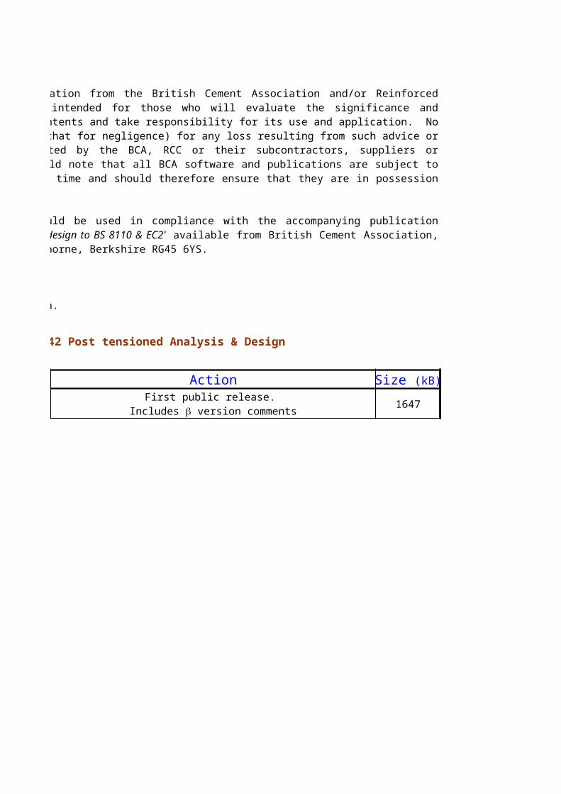
Action
1647
All advice or information from the British Cement Association and/or Reinforced Concrete Council is intended for those who will evaluate the significance and limitations of its contents and take responsibility for its use and application. No liability (including that for negligence) for any loss resulting from such advice or information is accepted by the BCA, RCC or their subcontractors, suppliers or advisors. Users should note that all BCA software and publications are subject to revision from time to time and should therefore ensure that they are in possession of the latest version.
This spreadsheet should be used in compliance with the accompanying publication 'Spreadsheets for concrete design to BS 8110 & EC2' available from British Cement Association, Telford Avenue, Crowthorne, Berkshire RG45 6YS.
Revision history RCC42 Post tensioned Analysis & Design
Size (kB)
First public release. Includes b version comments