Embed Size (px)
Citation preview

Wireless Sensor Network, 2010, 2, 472-482 doi:10.4236/wsn.2010.26059 Published Online June 2010 (http://www.SciRP.org/journal/wsn)
Copyright © 2010 SciRes. WSN
Interference Management for DS-CDMA Systems through Closed-Loop Power Control, Base Station Assignment, and
Beamforming
Mohamad Dosaranian Moghadam1, Hamidreza Bakhshi2, Gholamreza Dadashzadeh2 1Department of Electrical Engineering, Science and Research Branch of Islamic Azad University, Tehran, Iran
2Department of Electrical Engineering, Shahed University, Tehran, Iran E-mail: [email protected], {bakhshi, gdadashzadeh}@shahed.ac.ir
Received April 8, 2010; revised May 15, 2010; accepted May 23, 2010
Abstract
In this paper, we propose a smart step closed-loop power control (SSPC) algorithm and a base station as-signment method based on minimizing the transmitter power (BSA-MTP) technique in a direct se-quence-code division multiple access (DS-CDMA) receiver with frequency-selective Rayleigh fading. This receiver consists of three stages. In the first stage, with constrained least mean squared (CLMS) algorithm, the desired users’ signal in an arbitrary path is passed and the inter-path interference (IPI) is reduced in other paths in each RAKE finger. Also in this stage, the multiple access interference (MAI) from other users is reduced. Thus, the matched filter (MF) can use for more reduction of the IPI and MAI in each RAKE finger in the second stage. Also in the third stage, the output signals from the matched filters are combined accord-ing to the conventional maximal ratio combining (MRC) principle and then are fed into the decision circuit of the desired user. The simulation results indicate that the SSPC algorithm and the BSA-MTP technique can significantly reduce the network bit error rate (BER) compared to the other methods. Also, we observe that significant savings in total transmit power (TTP) are possible with our methods. Keywords: Adaptive Beamforming, Antenna Array, Base Station Assignment, Closed-Loop Power Control,
Constrained LMS, DS-CDMA
1. Introduction
Code-Division Multiple Access (CDMA) for cellular communication networks requires the implementation of some forms of adaptive power control. In uplink of CDMA systems, the maximum number of supportable users per cell is limited by multipath fading, shadowing, and near-far effects that cause fluctuations of the received power at the base station (BS). Two types of power con-trol are often considered: closed-loop power control and open-loop power control [1,2]. In a closed-loop power control, according to the received signal power at a base station, the base station sends a command to a mobile set to adjust the transmit power of the mobile. Also, closed- loop power control is employed to combat fast channel fluctuations due to fading. Closed-loop algorithms can effectively compensate fading variations when the power control updating time is smaller than the correlation time of the channel. However, in an open-loop power control, a mobile user adjusts its transmit power according to its
received power in downlink [1-5]. In this paper, an adap-tive closed-loop power control algorithm is proposed to compensate for near-far effects.
Diversity and power control are two effective techni- ques for enhancing the signal-to-interference-plus-noise ratio (SINR) for wireless networks. Diversity exploits the random nature of radio propagation by finding indep- endent (or, at least, highly uncorrelated) signal paths for communication. If one radio path undergoes a deep fade, another independent path may have a strong signal. By having more than one path to select from, the SINR at the receiver can be improved. The diversity scheme can be divided into three methods: 1) The space diversity; 2) The time diversity; 3) The frequency diversity. In these schemes, the same information is first received (or transmitted) at different locations (or time slots/freque- ncy bands). After that, these signals are combined to inc- rease the received SINR. The antenna array is an example of the space diversity, which uses a beamformer to incre- ase the SINR for a particular direction [6-8].

M. D. MOGHADAM ET AL. 473
The first goal of this paper is to extend the works in [9] and [10] by considering multiple-cell system and closed- loop power control. In these works, a RAKE receiver in single-cell system with conjugate gradient adaptive bea- mforming was proposed in the presence of frequency- selective Rayleigh fading channel, and perfect power control (PPC) was considered.
In this work, the performance analysis of direct sequence (DS)-CDMA system in frequency-selective Rayleigh fading channel has been studied. If the delay spread in a multipath channel is larger than a fraction of a symbol, the delayed components will cause inter-symbol interference (ISI). Adaptive receiver beamforming sch- emes have been widely used to reduce both co-channel interference (CCI) and ISI and to decrease the bit error rate (BER) by adjusting the beam pattern such that the effective SINR at the output of the beamformer is opti-mally increased [11].
In this paper a RAKE receiver in DS-CDMA system is analyzed in three stages according to Figure 1 [9]. In the first stage, this receiver uses constrained least mean squared (CLMS) adaptive beamforming algorithm to find optimum antenna weights assuming perfect estimation of the channel parameters (direction, delay, and power) for the desired user. The desired user resolvable paths’ directions are fed to the beamformer to reduce the inter-path interference (IPI) from other directions. Also, the RAKE receiver uses conventional demodulation in the second stage and conventional maximal ratio combining (MRC) in the third stage to reduce multiple access interference (MAI) and the other interferences. Reducing the MAI and CCI will further decrease the system BER.
To improve the performance of cellular systems, base station assignment (BSA) technique can be used. In the joint power control and base station assignment, a num- ber of base stations are potential receivers of a mobile
transmitter. Here, the objective is to determine the ass- ignment of users to base stations which minimizes the allocated mobile powers [12-15]. In simple mode and in multiple-cell systems, the user is connected to the nearest base station. This way is not optimal in cellular systems under the shadowing and multipath fading channels and can increase the system BER.
Accordingly, the second goal of this paper is to use base station assignment technique. In [14], the combined the base station assignment and power control was used to increase uplink capacity in cellular communication networks. In that work, it was shown that if there exists at least one feasible base station assignment, the prop- osed algorithm will find the jointly optimal base station assignment and minimal transmitter power level for all users. In this paper, we present the base station assignm- ent method based on minimizing the transmitter power (BSA-MTP) for decreasing the BER in all cells.
The organization of the remainder of this paper is as follows. The system model is presented in Section 2. The RAKE receiver structure is described in Section 3. In Section 4, we propose smart step closed-loop power con- trol (SSPC) algorithm. In Section 5, the BSA-MTP tech- nique is presented. Section 6 describes switched-beam (SB) technique and equal sectoring (ES) method. Finally, simulation results and conclusions are given in Section 7 and Section 8, respectively. 2. System Model
In this paper, we focus on the uplink communication paths in a DS-CDMA cellular system. replicas of the signal, due to both some form of diversity reception (for instance antenna diversity) and channel frequency selec- tivity, are assumed Rayleigh distributed and optimally combined through a RAKE receiver according to Figure 1.
L
Figure 1. Block diagram of a three-stage AKE receiver in DS-CDMA system [9]. R
Copyright © 2010 SciRes. WSN
474 M. D. MOGHADAM ET AL. Also assume that there are M active base stations in the network, with mK users connected to th base
station, where . Also assume that each base station uses an antenna array of sensors and weights, where , to receive signals from all users. Also, for simplicity we assume a synchronous DS- CDMA scheme and BPSK modulation in order to simp- lify the analysis of proposed methods. Additionally, in this paper we assume a slow fading channel. Hence, the received signal in the base station q and sensor
m
1 M
S
m
NS N
s
from all users can be written as [9,16]
, , , , ,1
, , , , ,
,
exp sin
L
q s k m k k m l k m k m lk l
k m k m l d k m l
r t p x y b t
c t j s k n t
, ,
c
(1)
where is the pseudo noise (PN) chips of user
in cell (user ) with a chip period of ;
is the information bit sequence of user
with a bit period of where G is processing
gain;
,k mc t
m
t
, ,k m l
k
,b
,k m
bT
cT
,k mk m
GT
is the l th path time delay for user ; ,k m
, ,k m l is the direction of arrival (DoA) in the th path
for user ;
l
,k m , ,k m l is the complex Gaussian fading
channel coefficient from the lth path of user ; ,k m
2 /ddk where is signal wavelength and d
is the distance between the antenna elements that for avoid the spatial aliasing should be defined as 0.5d
and is an additive white Gaussian noise (AWGN)
process with a two-sided power spectral density (PSD) of . Also for conventional BSA technique,
n t
0N / 2 ,k x y
is defined as
,
,
BS
/10,
/10,
1 ;
min , 10,;
, 10
k m
k
k q
q
Lk mk m
oLk q
k S
d x yx yk S
d x y
(2)
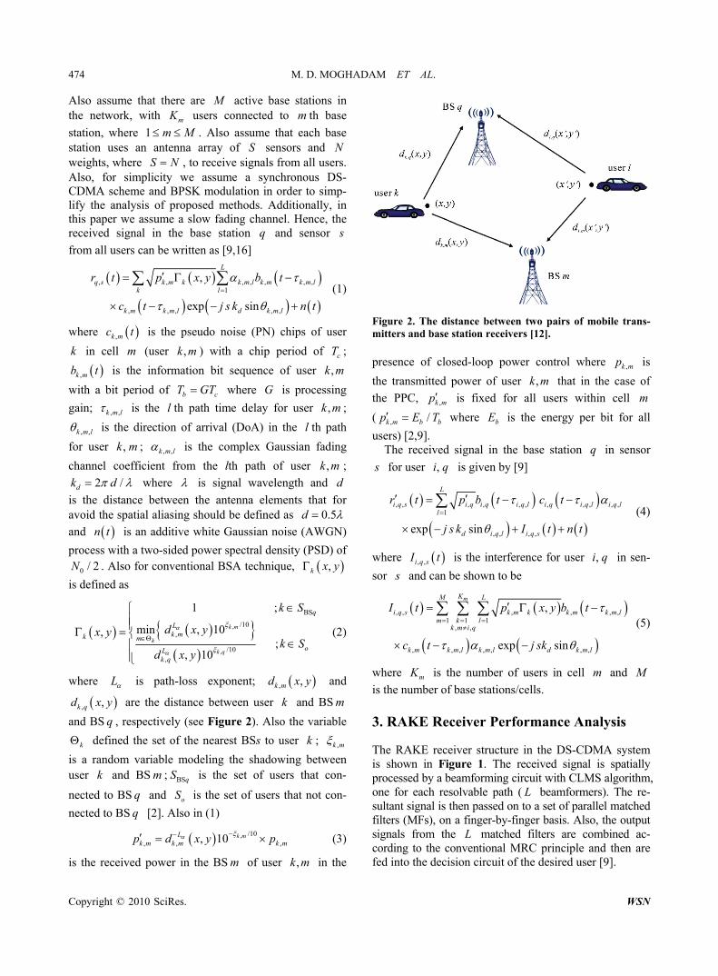
where L is path-loss exponent; and
are the distance between user and BS m
and BS , respectively (see Figure 2). Also the variable
defined the set of the nearest BSs to user ;
, ,k md x y
k
k
, ,k qd x
k
y
q
,k m
is a random variable modeling the shadowing between user and BS ; is the set of users that con-
nected to BS and is the set of users that not con-
nected to BS [2]. Also in (1)
k m BSqS
oSq
q
, /10, , , 10 k mL
k m k m k mp d x y p , (3)
is the received power in the BS of user in the m ,k m
Figure 2. The distance between two pairs of mobile trans- mitters and base station receivers [12]. presence of closed-loop power control where is
the transmitted power of user that in the case of
the PPC,
,k mp
,k m
,k mp is fixed for all users within cell
(
m
,k mp /b bE T where is the energy per bit for all
users) [2,9]. bE
The received signal in the base station in sensor q
s for user is given by [9] ,i q
, , , , , , , , , , ,1
, , , ,exp sin
L
i q s i q i q i q l i q i q l i q ll
d i q l i q s
r t p b t c t
j s k I t n t
(4)
where , ,i q sI t is the interference for user in sen-
sor
,i q
s and can be shown to be
, , , , , ,1 1 1
, ,
, , , , , , ,
,
exp sin
mKM L
i q s k m k k m k m lm k l
k m i q
k m k m l k m l d k m l
I t p x y b t
c t j sk
(5)
where mK is the number of users in cell and m M
is the number of base stations/cells. 3. RAKE Receiver Performance Analysis
The RAKE receiver structure in the DS-CDMA system is shown in Figure 1. The received signal is spatially processed by a beamforming circuit with CLMS algorithm, one for each resolvable path ( beamformers). The re-sultant signal is then passed on to a set of parallel matched filters (MFs), on a finger-by-finger basis. Also, the output signals from the matched filters are combined ac-cording to the conventional MRC principle and then are fed into the decision circuit of the desired user [9].
L
L
Copyright © 2010 SciRes. WSN
M. D. MOGHADAM ET AL. 475 3.1. Constrained LMS Algorithm
It is well known that an array of weights has N 1N degree of freedom for adaptive beamforming [9,16]. This means that with an array of weights, one can gener-ates pattern nulls and a beam maximum in des- ired directions. From (5), it is clear that the number of
users is
N1N
1
M
um
mK K
u
L
L
and the number of interferes is
. To null all of these interferes; one would have
to have weights, which is not practical. So, we
focus only on the paths of the desired user. Thus, the minimum number of the antenna array weights is where, typically, varies from 2 to 6 [9].
1LK
uLK
L
In this paper, we use the CLMS adaptive beamforming algorithm. This algorithm is a gradient based algorithm to minimize the total processor output power, based on the look direction constraint. The adaptive algorithm is designed to adapt efficiently in agreement with the envi-ronment and able to permanently preserve the desired frequency response in the look direction while minimiz-ing the output power of the array. The combined form of the constraint is called constraint for narrowband beam- forming [12,17].
This form consider a narrowband beamformer where the narrowband signal from each element of smart ant- enna are multiplied by the complex weight calculated by using narrowband adaptive beamforming algorithm, and then summed to produce the output of the array. The definition of the complex weights of this beamformer in the th iteration for user in the th path is as
follows [16,18].
n ,i q j
( ) ( ) ( ) ( ), , ,0 , ,1 , , 1...
Tj j j ji q i q i q i q Nn w n w n w n w (6)
Accordingly, the output of the array in the th itera-tion in the th path for user is given by
nj ,i q
( ) ( ), , ,
Hj ji q i q i qy n n n w r (7)
where . , , ,0 , ,1 , , 1...T
i q i q i q i q Nr r r r
The expected output power of the array in the th it-eration is given by
n
2 *( ) ( ) ( ), , ,
( ) ( ), , , ,
( ) ( ), ,
E E
E
j j ji q i q i q
H Hji q i q i q i q
Hj ji q r r i q
y n y n y n
n n n n
n n
w r r w
w R w
j
n
(8)
where is denoted the expectation and is the
correlation matrix of the received vector .
E . rr R
n,i qr
A real-time CLMS algorithm for determining the op-timal weight vector for user in the th path is
[17,18]:
,i q j
( ) ( ) ( ), , ,
( ) ( ), , , ,
1
1
j j ji q i q i q
j H ji q i q i q j
n n g
w w w
w a (9)
where
( ), , , , ,
, ,
[1 exp sin ...
...exp ( 1)sin ]
ji q i q j d i q j
Td i q
j k
j k N
a
j
(10)
denotes spatial response of the array for user in the
th path. Also in (9), is the new weight
computed at the
,i q
j ( ), 1j
i q n w
1n th iteration for user in the
th path. Also, the variable scalar
,i q
j denotes a posi-
tive scalar (gradient step size) that controls the conver- gence characteristic of the algorithm, that is, how fast and how close the estimated weights approach the optimal
weights, and ( ),j
i qg nw denotes an unbiased estimate of
the gradient of the power surface ( )
which is the expected output power of the array) with
respect to
( ), ,
Hj ji qn nw R w( )
i q r r
n( ),j
i qw after the nth iteration. The algorithm
is “constrained” because the weight vector satisfies the
constraint at each iteration, that is , , , , 1j Hi q j
( )i q
( )ji q w a .
Rewrite the CLMS algorithm as follows [17].
( ), , ,( ) ( ) ( ) ( )
, , , ,1j
i q i q jj j j ji q i q i q i qn n g n
N
aw β w w
(11)
where
( ) ( ), , , , , ,( )
,
Hj ji q i q j i q i q jj
i q N
a aβ I (12)
The gradient of with respect
to
( ) ( ),
Hji q r r i qn w R w ,
j n
( ),j
i q nw is given by [17]
( ) ( ) ( ), ,( )*
,
( ),2
Hj ji q i q r r i qj
i q
jr r i q
,jg n n
n
w w Rw
R w
nw (13)
and its computation using this expression requires knowledge of r r R , which normally is not available in
practice. For a standard LMS algorithm, an estimate of the gradient at each iteration is made by replacing r r R
by its noise sample , ,1 1H
i q i qn n r r available at
time instant 1n , leading to
( ) ( )*, , ,2 1j j
i q i q i q g n n y w r n (14)
Copyright © 2010 SciRes. WSN
476 M. D. MOGHADAM ET AL.
The CLMS is a fast convergence algorithm. However, it is drastically sensitive to the mismatch in the direction of arrival. Meanwhile, the weights estimated by the stan- dard algorithm are sensitive to the signal power, require- ing a lower step size in the presence of a strong signal for the algorithm to converge, which in turn regarding the decrease of mis-adjustment error, the convergence time is increased [17,19].
It should be mentioned that for the antenna arrays weight vector in the CLMS algorithm and for big ,
will converge after a few iteration (is approximately equal to the number of beamformer weights, i.e., n N ) [19].
Accordingly, the output signal from the th beam-
former ( ) can be written as [9]
j
1,...,j L
( ), , , , , , , , , ,
( ), ,
ji q i q i q i q j i q i q j i q j
j j ji q i q
y t p b t c t
I t I t n t
(15)
where is a zero mean Gaussian noise of vari-
ance
( )jn t
2n and ,
ji qI t , the IPI, is defined as
( ), , , , , , , ,
1
, , ,
Lj j
i q i q i q i q l i q l i q i q lll j
i q i q l
I t p g b t
c t
, ,
(16)
and ,j
i qI t , the MAI, is defined as
( ), ,
1 1 1, ,
, , , , , , , ,
,mKM L
j ji q k m k i q k m l
m k lk m i q
k m l k m k m l k m k m l
I t p x y g
b t c t
, , ,
(17)
where ( ),j
i qg is the magnitude response of the th
beamformer for user toward the DoA
j
,i q [9].
3.2. Matched Filter
Using beamforming in the first stage, will reduce the IPI for the desired user and the MAI from the other users whose signals arrive at different angles from the desired user signal (out-beam interference). Now, in the second stage of the RAKE receiver, the output signal from the
th beamformer is directly passes on to a filter matched
to the desired user’s signature sequence. The th matched
filter output corresponding to the th bit is [9]:
j
j
n
( ) ( ), , , , , ,
( ) ( ),
ji q i q i q i q j i q
j ji q
z n p b n I n
I n n n
j
(18)
where
, ,
, ,
( ), , ,
( 1)
1 b i q j
b i q j
nTjj
i q i q i q i q jb n T
, ,I n I t c tT
dt (19)
, ,
, ,
( ), , ,
( 1)
1 b i q j
b i q j
nTjj
i q i q i q i q jb n T
, ,I n I t c tT
dt (20)
and
, ,
, ,
( ) ( ), , ,
( 1)
1 b i q j
b i q j
nT
j ji q i q j
b n T
n n n t c t dT
t
(21)
If we assume that the paths’ delays from all users are
less than the symbol duration for all users’
signals on all paths, the th bit IPI and MAI at the out-put of the th matched filter are expressed as [9]
, , k m l bT
nj
( ) ( ), , , , , , ,
1
, , , , ,
Lj j
i q i q i q i q l i q l i qll j
i i i q j i q l
,I n p g b
R
n (22)
and
( ) ( ), ,
1 1 1, ,
, , , , , , , ,
,mKM L
j ji q k m k i q k m l
m k lk m i q
k m l k m i k i q j k m l
I n p x y g
b n R
, , ,
(23)
where the autocorrelation function ,i kR is [9,20]:
, , ,
1
b
i k i q k mb T
R c t c tT
dt (24)
If all users’ delays are multiples of the chip period ( ), then cT
1 2
1 1
, , 1 , 2 10 0
1 G G
i k i q k m c cl l
R c l c l R lG
2l T (25)
where the autocorrelation function cR is:
1
b
cb T
R c t c tT
dt (26)
In the case of a maximal-length sequence (m-sequence) and for 0 bT , we have [20]:
1 1 1/ ;
1/ ;
ccc
c
G TTR
G T
(27)
3.3. Maximal Ratio Combining
Diversity combining has been considered as an efficient way to combat multipath fading because the combined
Copyright © 2010 SciRes. WSN

M. D. MOGHADAM ET AL. 477
Copyright © 2010 SciRes. WSN
SINR is increased compared with the SINR of each div- ersity branch. The optimum combiner is the MRC whose SINR is the sum of the SINR’s of each individual diver- sity branch [20,21].
minimized, but at the same time, the user SINRs satisfies the system quality of service (QoS) requirements [23].
Depending on the location where the decision on how to adjust the transmitted powers is made, the power con- trol algorithm can be divided into two groups: central-ized power control and distributed power control [1-6, 12]. In centralized power control, a network center can simultaneously compute the optimal power levels for all users. However, it requires measurement of all the link gains and the communication overhead between a net- work center and base stations. Thus, it is difficult to re- alize in a large system [24]. Distributed power control, on the other hand, uses only local information to deter- mine transmitter power levels. It is much more scalable than centralized power control. However, transmitter power levels may not be optimal, resulting in perform- ance degradation [25].
After the finger-matched filter, the fingers’ signals are combined according to the MRC principle in the third stage of the RAKE receiver. In this paper, we use the conventional MRC that the signal of user in the
th path is combined using multiplying by the complex
conjugate of
,i q
j
, ,i q j .
The SINR in output of the RAKE receiver for user is [9,21]: ,i q
1
SINR SINRL
(j)i,q i,q
j
(28)
where The distributed closed-loop power control problem has
been investigated by many researchers from many per- spectives during recent years [4,23,26]. For instance, the conventional fast closed-loop power control strategy used in practice in CDMA systems is a fixed step con- troller based on SINR measurements. The fixed step closed-loop power control (FSPC) algorithm is defined by [4]
2
, , ,
2 2( ) ( ) ( ), ,
SINRE E E
i q i q j(j)i,q
j ji q i q
p
I I n
2j (29)
is the SINR in output of the RAKE receiver in path
for user .
j
,i q
Also, we can be rewritten the SINR in (29) by (30), that shown at the bottom of the page, where ,k x y
E ,k x y and 22, , , ,Ek m j k m j [9,22].
1 *, , , ,signn n n
i q i q i q i qp p (33)
where ,ni qp , *
,i q , and ,n
i q are the transmitter power,
SINR target, and measured SINR of user at time ,i q
n , respectively, and is the fixed step size. Also 1
,ni qp is transmitter power control (TPC) command in
the feedback link of the base station to user at time ,i q
1n (all signals are in decibels).
In order to perform the BER, we assume Gaussian ap- proximation for the probability density function of inter- ference plus noise. The conditional BER for a BPSK modulation is [9,20]:
BER 2 SINRi,q i,qQ (31)
Also, the distributed traditional closed-loop power control (DTPC) is defined by [23] the variance of
where
21exp / 2
2 x
Q x u du
(32) *,1
,,
i qni q i qn
i q
p ,
np (34)
4. Smart Step Closed-Loop Power Control
Algorithm In both algorithms, the simple intuition behind this it-
eration is that if the current SINR ,n
i q of user is
less than the target SINR
,i q*,i q , then the power of that
user is increased; otherwise, it is decreased. It should be mentioned that convergence speed of DTPC algorithm is higher than FSPC algorithm. Also, the SINR mis-
A major limiting factor for the satisfactory performance of CDMA systems is the near-far effect. Power control is an intelligent way of adjusting the transmitted powers in cellular systems so that the total transmit power (TTP) is
2
, , ,
2 22 ( ) 2 2 ( ) 2 0, , , , , , , , , , , , , , , , , , , , , ,
1 1 1 1, ,l j k m i q
SINR
,2
m
(j)i,q
i q i q j
KL M Lj j
i q i q j i q i q l i i i q j i q l k m k k m j i q k m l i k i q j k m ll m k l b
p
Np g R p x y g R
T
(30)
478 M. D. MOGHADAM ET AL. adjustment in FSPC algorithm is higher than DTPC al-gorithm. But, it has been shown that the FSPC algorithm
converge to a bound region *, , 2n
i q i q ldk , where
is the loop delay [4]. ldk
Also in [26], variable step closed-loop power control (VSPC) algorithm has been proposed. In this algorithm, variable step size is discrete with mode . It is shown
that the performance of VSPC algorithm with mode is found to be worse than that of a fixed step
algorithm ( ) under practical situations with loop
delay of two power control intervals, but the conver- gence speed of VSPC algorithm is higher than FSPC algorithm. Also in this algorithm, the variance of the SINR mis-adjustment is reduced in compared to FSPC algorithm.
vq
4vq 1vq
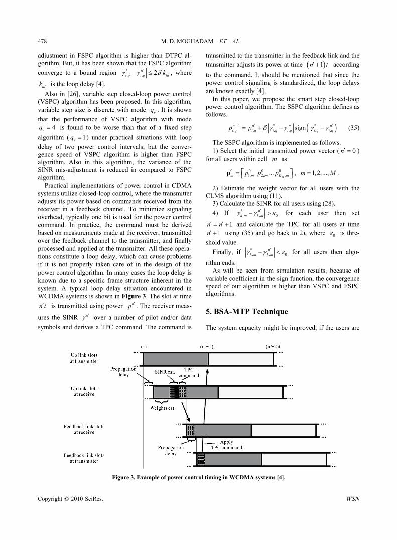
Practical implementations of power control in CDMA systems utilize closed-loop control, where the transmitter adjusts its power based on commands received from the receiver in a feedback channel. To minimize signaling overhead, typically one bit is used for the power control command. In practice, the command must be derived based on measurements made at the receiver, transmitted over the feedback channel to the transmitter, and finally processed and applied at the transmitter. All these opera- tions constitute a loop delay, which can cause problems if it is not properly taken care of in the design of the power control algorithm. In many cases the loop delay is known due to a specific frame structure inherent in the system. A typical loop delay situation encountered in WCDMA systems is shown in Figure 3. The slot at time
is transmitted using power . The receiver meas-
ures the SINR
n t np
n over a number of pilot and/or data
symbols and derives a TPC command. The command is
transmitted to the transmitter in the feedback link and the transmitter adjusts its power at time according
to the command. It should be mentioned that since the power control signaling is standardized, the loop delays are known exactly [4].
1n t
In this paper, we propose the smart step closed-loop power control algorithm. The SSPC algorithm defines as follows.
1 * *, , , , , ,signn n n n
i q i q i q i q i q i qp p (35)
The SSPC algorithm is implemented as follows. 1) Select the initial transmitted power vector ( 0n )
for all users within cell as m
0 0 0 01, 2, ,...
mm m m K mp p p p , . 1, 2,...,m M
2) Estimate the weight vector for all users with the CLMS algorithm using (11).
3) Calculate the SINR for all users using (28).
4) If *, ,
nk m k m 0 for each user then set
1n n 1n
and calculate the TPC for all users at time using (35) and go back to 2), where 0 is thre-
shold value.
Finally, if *, ,
nk m k m 0 for all users then algo-
rithm ends. As will be seen from simulation results, because of
variable coefficient in the sign function, the convergence speed of our algorithm is higher than VSPC and FSPC algorithms.
5. BSA-MTP Technique
The system capacity might be improved, if the users are
Figure 3. Example of power co ntrol timing in WCDMA systems [4].
Copyright © 2010 SciRes. WSN

M. D. MOGHADAM ET AL. 479 allowed to switch to alternative base stations, especially when there are congested areas in the network. Obvi- ously, when uplink performance is of concern, the switching should happen based on the total interferences seen by the base stations [15].
So far, we have considered the power control problem for a number of transmitter-receiver pairs with fixed as- signments, which can be used in uplink or downlink in mobile communication systems. In an uplink scenario where base stations are equipped with antenna arrays, the problem of joint power control and beamforming, as well as base station assignment, naturally arises [12].
In this paper, we modify the BSA-MTP technique to support base station assignment as well. The modified technique can be summarized as follows.
1) Initially by the conventional BSA technique, each mobile connects to its base station, according to (2).
2) Estimate the weight vector for all users with the CLMS algorithm.
3) Each mobile updates its transmitted power based on the SSPC algorithm using (35).
4) Finally, /r uK K M users that their transm-
itted power is higher than the other users to be transfe- rred to other base stations according to the following equation, where the function x returns the integer
portion of a number x .
,
,
,
,
BS
/10,
/10 BS,
/10,
/10,
1 ;
min , 10
,, 10
min , 10;
, 10
k m
k
k q
k m
k
k q
q
Lk m
mm q
k qLk q
Lk m
moL
k q
k S
d x y
;x y kd x y
d x yk S
d x y
S (36)
where BSq
S is the set of users that are in cell but not
connected to BS [2].
q
q
It should be mentioned that the technique for users that are present in the border of cells, the BER can be effect- tively reduced. 6. Switched-Beam Technique and Equal
Sectoring Method
One simple alternative to the fully adaptive antenna is the switched-beam architecture in which the best beam is chosen from a number of fixed steered beams. Switched- beam systems are technologically the simplest and can be implemented by using a number of fixed, independent, or directional antennas [27]. We list the SB technique conditions for this paper as follows.
1) Coverage angle for all beams is and overlap between consecutive beams is . Thus each base sta-tion has 36 beams.
30
20
2) Each user can be use one beam for its each path to communicate with a base station at any time
Also, one of simple methods to sectorize a cell is equal sectoring, in which all sectors have the same coverage angle. In this paper, we assume three sectors for each base station with sector angle for the ES method. 120
7. Simulation Results
We consider 4M base stations for a four-cell CDMA system on a 2 2 grid as Figure 4. We assume
a uniform linear array of omni-directional antennas in each base station with antenna spacing
S/ 2d .
Also, we assume BPSK m-sequence code spreading with processing gain 64G ; resolution ; the input data rate
1R 9.6 kbpsbT ; the number of antenna weights
3N ; the number of antenna sensors ; threshold value
3S
0 0.1 dB ; frequency-selective fading channel
with 2L resolvable propagation paths; variance of
the complex Gaussian fading channel coefficient 2
4dB ; fixed step size for SSPC, FSPC, and VSPC
algorithms 0.01 ; mode for VSPC algo-
rithm [26]; variance of the log-normal shadow fading
; path-loss component ; initial value
for weight vectors in the CLMS algorithm
4vq
L2 8 dB 4
0 w 00m
;
initial value for transmitted power vectors p 0 . The
SINR target value is the same for all users and is set to
dB* 5 7 . It also is assumed that the distribution of
users in all cells is uniform. First, in order to compare the BSA-MTP and conven- tional BSA techniques, we assume the PPC, and the BER
Figure 4. Location plot of base stations and users in four cells.
Copyright © 2010 SciRes. WSN

480 M. D. MOGHADAM ET AL. has been calculated from (31). Finally, we compare the TTP with the joint SSPC algorithm and BSA-MTP tech- nique in comparison with other methods.
Figure 5 shows the average BER versus the sig-nal-to-noise ratio (SNR) for different receivers (one, two, and three-stage receivers) in the case of 32uK
active users and the PPC case. It should be mentioned that in this simulation, users can to be trans-
ferred to other base stations with the BSA-MTP tech-nique. Also in this simulation we use CLMS algorithm or SB technique in the first stage of the RAKE receiver. It is clear that, in MF only receiver (one-stage receiver) and in the case of the conventional BSA technique, we still have the error floor at high SNR. Using CLMS and MRC receiver (two-stage RAKE receiver) or CLMS, MF, and MRC receiver (the three-stage RAKE receiver as Figure 1) has a better performance than using MF only. Also observe that using the BAS-MTP technique in the case of three-stage RAKE receiver (CLMS me-thod in the first stage), the average BER is lower than the conventional BSA technique. For example, at a SNR of 20 dB, the average BER is 0.0096 for the three-stage RAKE receiver with the conventional BSA technique, while for the BSA-MTP technique, the av-erage BER is 0.0031. Also it can be seen that the aver-age BER in the SB technique is less than the CLMS algorithm. Also, it is clear that the MAI is not removed totally and the performance is still worse than the single user per cell bound.
8rK
Figure 6 shows the average BER versus the number of active users ( uK ) for different receivers as Figure 5, in
the case of the PPC and . At a BER of 0.005, the three-stage RAKE receiver (CLMS method in the first stage) with the BSA-MTP technique support
users, while for the three-stage RAKE receiver
and the conventional BSA technique support
SNR 10 dB
29uK 18uK
users. We also observe that the three-stage RAKE re- ceiver can achieve lower BER than the one and two- stage receivers. Also at a BER of 0.002, the three-stage RAKE receiver for the SB technique in the first stage and for the BSA-MTP technique support users, while the CLMS, MF, and MRC receiver support
users. It should be mentioned that increasing the number of active users in the SB technique, will lead more complexity in receiver in comparison with the CLMS algorithm. Also increasing the number of active users (
49uK
18uK
uK ), will increase the number of users that can to
be transferred to other base stations ( rK ) in the BSA- MTP technique.
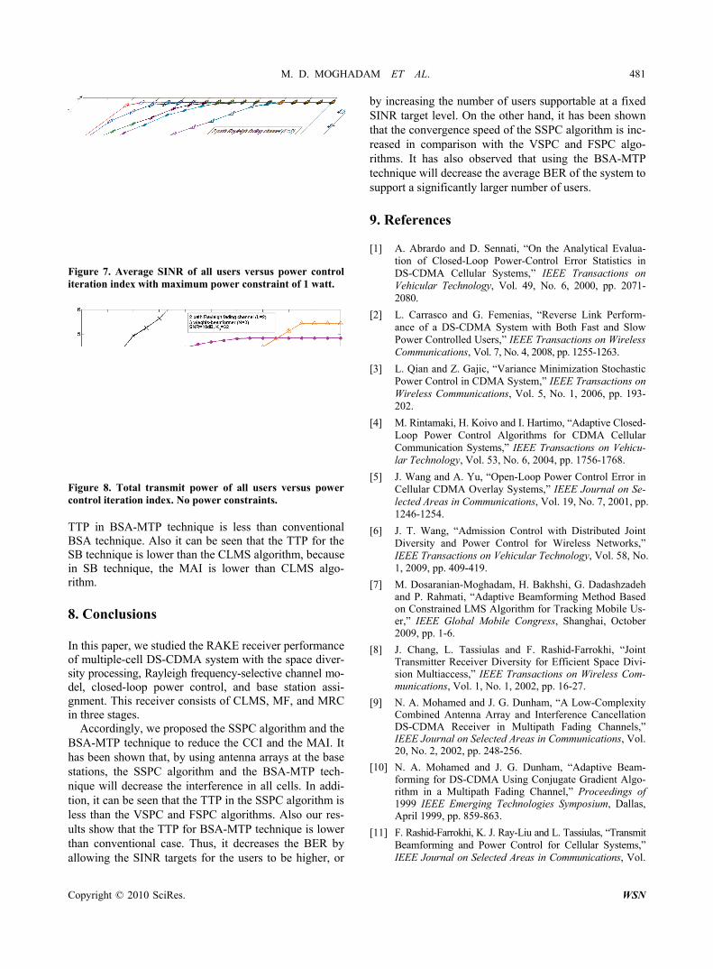
Figure 7 shows the comparison of the average SINR achieved over users versus the power control
iteration index ( n ) for SSPC, VSPC, and FSPC algo-rithms and for BSA-MTP and conventional BSA tech
32uK
Figure 5. Average BER of all users versus the SNR for the PPC case.
Figure 6. Average BER for all users versus the number of active users for the PPC case and SNR = 10 dB. niques. In this simulation, the three-stage RAKE receiver uses CLMS, SB, or ES methods in the first stage. Also, we assume that each user to have a maximum power constraint of 1 watt. Accordingly, we observe that the convergence speed of the SSPC algorithm is faster than the VSPC and FSPC algorithms. The figure also shows that the SSPC algorithm with the BSA-MTP technique converges faster than the SSPC algorithm for the con-ventional BSA technique. In addition, we see that the convergence speed of the SSPC algorithm for the SB technique is faster than the CLMS and ES methods. Also observe that the average SINR level achieved is below the target SINR value for the ES method, because in this method, the MAI is much higher than SB technique and CLMS algorithm.
Figure 8 shows the comparison of TTP usage versus the power control iteration index ( ) when there are n
32uK users in all cells according to Figure 7. But in
this simulation, we assume that users have no maximum power constraints. Similar to Figure 7, we observe that the ES method never can achieve the target SINR value. Also this figure shows that the SSPC algorithm offers more savings in the TTP as compared to the VSPC and FSPC algorithms. In addition, the figure shows that the
Copyright © 2010 SciRes. WSN
M. D. MOGHADAM ET AL. 481
Figure 7. Average SINR of all users versus power control iteration index with maximum power constraint of 1 watt.
Figure 8. Total transmit power of all users versus power control iteration index. No power constraints. TTP in BSA-MTP technique is less than conventional BSA technique. Also it can be seen that the TTP for the SB technique is lower than the CLMS algorithm, because in SB technique, the MAI is lower than CLMS algo- rithm. 8. Conclusions In this paper, we studied the RAKE receiver performance of multiple-cell DS-CDMA system with the space diver- sity processing, Rayleigh frequency-selective channel mo- del, closed-loop power control, and base station assi- gnment. This receiver consists of CLMS, MF, and MRC in three stages.
Accordingly, we proposed the SSPC algorithm and the BSA-MTP technique to reduce the CCI and the MAI. It has been shown that, by using antenna arrays at the base stations, the SSPC algorithm and the BSA-MTP tech- nique will decrease the interference in all cells. In addi- tion, it can be seen that the TTP in the SSPC algorithm is less than the VSPC and FSPC algorithms. Also our res- ults show that the TTP for BSA-MTP technique is lower than conventional case. Thus, it decreases the BER by allowing the SINR targets for the users to be higher, or
by increasing the number of users supportable at a fixed SINR target level. On the other hand, it has been shown that the convergence speed of the SSPC algorithm is inc- reased in comparison with the VSPC and FSPC algo- rithms. It has also observed that using the BSA-MTP technique will decrease the average BER of the system to support a significantly larger number of users.
9. References
[1] A. Abrardo and D. Sennati, “On the Analytical Evalua-tion of Closed-Loop Power-Control Error Statistics in DS-CDMA Cellular Systems,” IEEE Transactions on Vehicular Technology, Vol. 49, No. 6, 2000, pp. 2071- 2080.
[2] L. Carrasco and G. Femenias, “Reverse Link Perform- ance of a DS-CDMA System with Both Fast and Slow Power Controlled Users,” IEEE Transactions on Wireless Communications, Vol. 7, No. 4, 2008, pp. 1255-1263.
[3] L. Qian and Z. Gajic, “Variance Minimization Stochastic Power Control in CDMA System,” IEEE Transactions on Wireless Communications, Vol. 5, No. 1, 2006, pp. 193- 202.
[4] M. Rintamaki, H. Koivo and I. Hartimo, “Adaptive Closed- Loop Power Control Algorithms for CDMA Cellular Communication Systems,” IEEE Transactions on Vehicu-lar Technology, Vol. 53, No. 6, 2004, pp. 1756-1768.
[5] J. Wang and A. Yu, “Open-Loop Power Control Error in Cellular CDMA Overlay Systems,” IEEE Journal on Se-lected Areas in Communications, Vol. 19, No. 7, 2001, pp. 1246-1254.
[6] J. T. Wang, “Admission Control with Distributed Joint Diversity and Power Control for Wireless Networks,” IEEE Transactions on Vehicular Technology, Vol. 58, No. 1, 2009, pp. 409-419.
[7] M. Dosaranian-Moghadam, H. Bakhshi, G. Dadashzadeh and P. Rahmati, “Adaptive Beamforming Method Based on Constrained LMS Algorithm for Tracking Mobile Us-er,” IEEE Global Mobile Congress, Shanghai, October 2009, pp. 1-6.
[8] J. Chang, L. Tassiulas and F. Rashid-Farrokhi, “Joint Transmitter Receiver Diversity for Efficient Space Divi-sion Multiaccess,” IEEE Transactions on Wireless Com-munications, Vol. 1, No. 1, 2002, pp. 16-27.
[9] N. A. Mohamed and J. G. Dunham, “A Low-Complexity Combined Antenna Array and Interference Cancellation DS-CDMA Receiver in Multipath Fading Channels,” IEEE Journal on Selected Areas in Communications, Vol. 20, No. 2, 2002, pp. 248-256.
[10] N. A. Mohamed and J. G. Dunham, “Adaptive Beam-forming for DS-CDMA Using Conjugate Gradient Algo-rithm in a Multipath Fading Channel,” Proceedings of 1999 IEEE Emerging Technologies Symposium, Dallas, April 1999, pp. 859-863.
[11] F. Rashid-Farrokhi, K. J. Ray-Liu and L. Tassiulas, “Transmit Beamforming and Power Control for Cellular Systems,” IEEE Journal on Selected Areas in Communications, Vol.
Copyright © 2010 SciRes. WSN
482 M. D. MOGHADAM ET AL.
Copyright © 2010 SciRes. WSN
16, No. 8, 1998, pp. 1437-1450.
[12] F. Rashid-Farrokhi, L. Tassiulas and K. J. Ray-Liu, “Joint Optimal Power Control and Beamforming in Wireless Networks Using Antenna Arrays,” IEEE Transactions on Communications, Vol. 46, No. 10, 1998, pp. 1313-1324.
[13] R. D. Yates and C. Huang, “Integrated Power Control and Base Station Assignment,” IEEE Transactions on Vehicu-lar Technology, Vol. 44, No. 3, 1995, pp. 638-644.
[14] S. V. Hanly, “An Algorithm for Combined Cell-Site Se-lection and Power Control to Maximize Cellular Spread Spectrum Capacity,” IEEE Journal on Selected Areas in Communications, Vol. 13, No. 7, 1995, pp. 1332-1340.
[15] M. Mahmoudi and E. S. Sousa, “Joint Power Control, Base Station Assignment and Sectorization for CDMA Cellular Systems,” Proceedings of 2000 IEEE Vehicular Technology Conference, Boston, September 2000, pp. 573-580.
[16] J. Litva and T. Kwok-Yeung, “Digital Beamforming in Wireless Communications,” Artech House, Boston, 1996.
[17] X. Y. Sun, X. H. Lian and J. J. Zhou, “Robust Adaptive Beamforming Based on Maximum Likelihood Estimation,” International Conference on Microwave and Millimeter Wave Technology, Nanjing, April 21-24, 2008, pp. 1137- 1140.
[18] M. Z. Shakir and T. S. Durrani, “Narrowband Beamform-ing Algorithm for Smart Antennas,” International Bhurban Conference on Applied Sciences & Technology, Islamabad, Pakistan, January 2007, pp. 49-54.
[19] S. Haykin, “Adaptive Filter Theory,” 3rd Edition, Pren-tice Hall, New Jersey, 1996.
[20] R. L. Peterson, R. E. Ziemer and D. E. Borth, “Spread- Spectrum Communications,” Prentice-Hall, New Jersey, 1995.
[21] N. Kong and L. B. Milstein, “Average SNR of a GeneralIzed Diversity Selection Combining Scheme,” IEEE Commu- nications Letters, Vol. 3, No. 3, 1999, pp. 57-59.
[22] J. C. Liberti and T. S. Rappaport, “Smart Antennas for Wireless Communications IS-95 and Third Generation CDMA Applications,” Prentice-Hall, New Jersey, 1999.
[23] A. Yener, R. D. Yates and S. Ulukus, “Interference Management for CDMA Systems through Power Control, Multiuser Detection, and Beamforming,” IEEE Transac-tions on Communications, Vol. 49, No. 9, 2001, pp. 1227-1239.
[24] S. Grandhi, R. Vijayan and D. Goodman, “Centralized Power Control in Cellular Radio Systems,” IEEE Trans-actions on Vehicular Technology, Vol. 42, No. 4, 1993, pp. 466-468.
[25] S. Grandhi, R. Vijayan and D. Goodman, “Distributed Power Control in Cellular Radio Systems,” IEEE Trans-actions on Communications, Vol. 42, No. 2-4, 1994, pp. 226-228.
[26] A. Kurniawan, “Effect of Feedback Delay on Fixed Step and Variable Step Power Control Algorithm in CDMA Systems,” The 8th International Conference on Commu-nication Systems, Indonesia, 2002, pp. 1096-1100.
[27] B. Allen and M. Beach, “On the Analysis of Switched- beam Antennas for the W-CDMA Downlink,” IEEE Tra- nsactions on Vehicular Technology, Vol. 53, No. 3, 2004, pp. 569-578.