Embed Size (px)
Citation preview

IEEE TRANSACTIONS ON VEHICULAR TECHNOLOGY, VOL. 52, NO. 6, NOVEMBER 2003 1447
Adaptive Predictive Power Control for theUplink Channel in DS-CDMA Cellular Systems
Mansour A. Aldajani, Member, IEEE,and Ali H. Sayed, Fellow, IEEE
Abstract—In this paper, we analyze the conventional closed-looppower-control system. We explain that the system behaves es-sentially as a companded delta modulator and then derive anexpression for the power-control error in terms of the channelfading, which suggests methods for reducing the error variance.This is achieved by using a prediction technique for estimating thechannel-power fading profile. The prediction module is combinedwith several proposed schemes for closed-loop power control.The resulting architectures are shown to result in improvedperformance in simulations.
Index Terms—Adaptive filtering, channel inverse coding, closedloop, direct sequence code division multiple access (DS-CDMA),error analysis, power control, prediction, Rayleigh fading.
I. INTRODUCTION
T HE requirement of power control (PC) in the uplink di-rect-sequence code-division multiple-access (DS-CDMA)
system is a critical limitation [1]. Power control is needed be-cause all users share the same bandwidth and, thus, interuserinterference is bound to occur. Without power control, a signalreceived by the base station (BS) from a nearby mobile station(MS) will dominate the signal from a far-away MS, resultingin the so-callednear–far effect. The objective of power controlis to control the transmitted power by the mobile units so thatthe average power received from each unit is generally constant.Some of the main advantages of power control can be summa-rized as follows.
1) Power control reduces interuser interference by over-coming the near–far effect, which results in capacityincrease of the overall CDMA system.
2) Power control combats the Rayleigh-fading channel effecton the transmitted signal by compensating for the fastfading of the wireless channel. This reduces the requiredsignal-to-noise ratio (SNR) . In perfect power-con-trol conditions, power control turns a fading channel intoan additive white Gaussian noise (AWGN) [1].
3) Power control minimizes the power consumption of themobile units. Instead of using a fixed maximum powerby the MS, it will now use an adaptive transmission powerbased on the power-control requirements.
Manuscript received May 22, 2001; revised March 13 and July 23, 2003.Dr. Sayed’s work was supported in part by National Science Foundation GrantCCR-0208573.
M. A. Aldajani is with King Fahd University of Petroleum and Minerals,Dhahran 31261, Saudi Arabia (e-mail: [email protected]).
A. H. Sayed is with the Electrical Engineering Department, University ofCalifornia, Los Angeles, CA 90095 USA.
Digital Object Identifier 10.1109/TVT.2003.819448
In closed-loop power control (CLPC), the BS measures thefading effects in the signal received from each mobile stationby measuring the signal power and the bit-error rate (BER).Typically, the received power is measured by averaging mul-tiple samples of the received sequence, while the BER is com-puted by comparing the received sequence with a predeterminedtransmitted sequence. The BS then compares these quantitieswith a reference point. Based on this comparison, the BS trans-mits a one-bit signal, known as thepower bit, to each MS, com-manding it to either increase or decrease its power by a fixedamount, e.g., 1, 0.5, or 0.25 dB. The power bit rate is 800 Hzin IS-95 standards and 1500 Hz in 3G WCDMA standards.Fig. 1 shows a block-diagram representation of the conventionalCLPC scheme. In the downlink channel, power control is not re-quired since all signals to the different MS are initiated from thesame source.
A. Limitations of Conventional CLPC
The performance of conventional CLPC is limited for at leasttwo reasons. First, the delta modulator-like behavior of the con-ventional CLPC is slow in tracking fast and deep fading of thewireless channel. This effect creates what is known in the delta-modulation context asslope overload. In addition, the CLPCcreates a noisy response known asgranular noisewhen thefading is smooth or minimal. In the literature, there are two mainmethods that have been used to improve the performance of theconventional CLPC, namely adaptive step size and predictivepower control.
In adaptive step-size power control, the step size of thepower-error quantizer is adapted in a way to cope with quicklychanging channel-fading effects. Examples of such schemescan be found in [2]–[6]. Predictive power control, on the otherhand, is based on predicting the channel attenuation one stepahead [7]–[9]. The predicted value is then used in calculatingthe predicted received power.
In this paper, we start from the power-control loop of Fig. 1.We derive a closed-form expression for the power error in termsof the channel fading and the desired power, and use this ex-pression to evaluate the mean and variance of the power-errorsignal. We then propose four algorithms that attempt to mini-mize the error variance. These algorithms require the predictionof the channel fading (a prediction scheme is developed for thispurpose). Simulations of the proposed algorithms show an im-proved power-control performance over conventional CLPC.
For the sake of simplicity, two assumptions are made in thispaper. First, it is assumed that the received power is estimatedwith no errors (i.e., the estimated power equals the received
0018-9545/03$17.00 © 2003 IEEE
1448 IEEE TRANSACTIONS ON VEHICULAR TECHNOLOGY, VOL. 52, NO. 6, NOVEMBER 2003
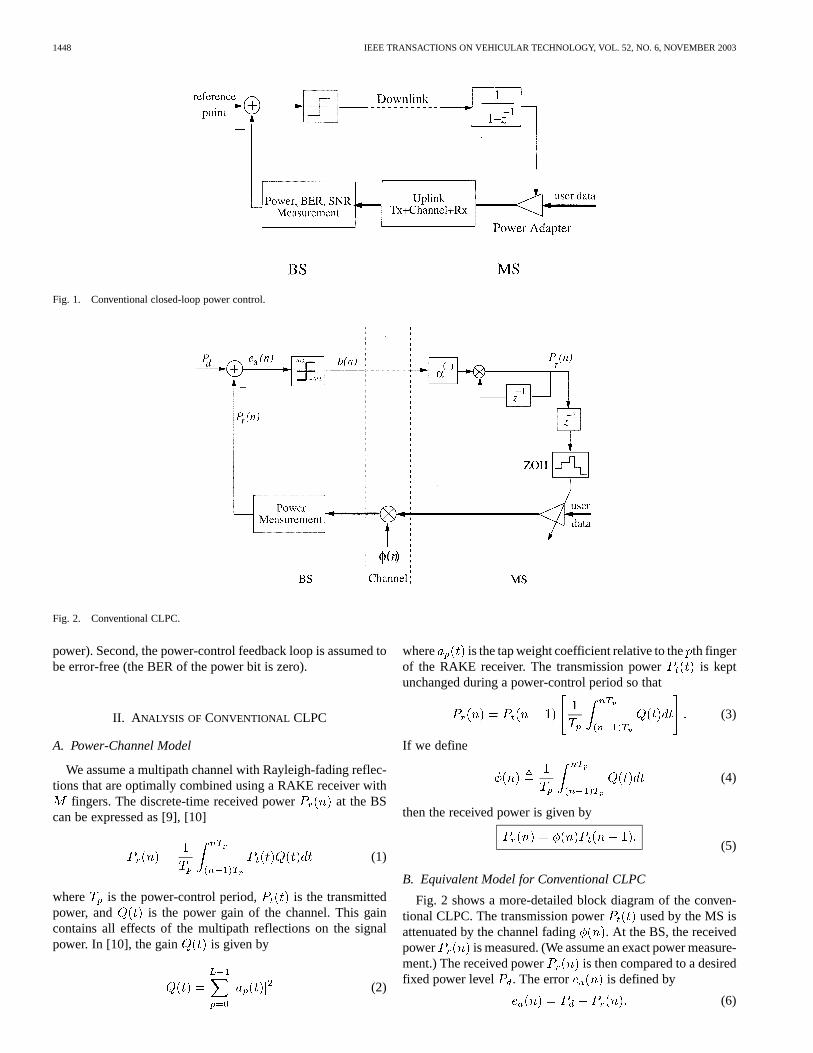
Fig. 1. Conventional closed-loop power control.
Fig. 2. Conventional CLPC.
power). Second, the power-control feedback loop is assumed tobe error-free (the BER of the power bit is zero).
II. A NALYSIS OF CONVENTIONAL CLPC
A. Power-Channel Model
We assume a multipath channel with Rayleigh-fading reflec-tions that are optimally combined using a RAKE receiver with
fingers. The discrete-time received power at the BScan be expressed as [9], [10]
(1)
where is the power-control period, is the transmittedpower, and is the power gain of the channel. This gaincontains all effects of the multipath reflections on the signalpower. In [10], the gain is given by
(2)
where is the tap weight coefficient relative to theth fingerof the RAKE receiver. The transmission power is keptunchanged during a power-control period so that
(3)
If we define
(4)
then the received power is given by
(5)
B. Equivalent Model for Conventional CLPC
Fig. 2 shows a more-detailed block diagram of the conven-tional CLPC. The transmission power used by the MS isattenuated by the channel fading . At the BS, the receivedpower is measured. (We assume an exact power measure-ment.) The received power is then compared to a desiredfixed power level . The error is defined by
(6)

ALDAJANI AND SAYED: ADAPTIVE PREDICTIVE POWER CONTROL FOR UPLINK CHANNEL 1449
Fig. 3. Equivalent structure for conventional CLPC.
Equivalently, using (5), we can write
(7)
The power error is quantized using a one-bit quantizer toproduce the power-command bit (PCB) , scaled by half thestep size of the quantizer, i.e.,1
sign (8)
This PCB is transmitted to the MS, which then increments ordecrements its transmission power by a fixed amount (in deci-bels), say
(9)
where is a constant (usually ). In other words,is incremented or decremented bydB where
(10)
If we take the logarithm of both sides of (9)
(11)
and use (7) and (8), we get
sign (12)
Now, since the logarithm is an increasing function, we canrewrite this equation as
sign (13)
Equivalently
sign (14)
Therefore
sign (15)
Substituting this expression into (11), we get
sign (16)
This expression shows that, in the logarithmic scale, the rela-tion between amounts to a delta-modulation (DM)scheme with input and output , asshown in Fig. 3. The logarithm function is added before the
1We shall assume that the error signale (n) is small enough so that thesingle-bit quantizer of Fig. 2 behaves like the signum function in (8).
DM, while an exponential function is added after the DM to get.
In other words, the result (16) shows that the conventionalCLPC model of Fig. 2 is actually a companded delta modulatorwith input and output . In this way, the CLPCattempts to make the transmission power track the quan-tity using a companded delta modulator. The resultsobtained in this section essentially match thelog-linear modelused in [10] and [11]. Now, we continue with a linear anal-ysis model by following the method of [12] on companded DMsystems.
C. Power-Control Error
DM is a simple tracking mechanism that is used in codingand data conversion. Fig. 4(a) shows a block diagram of a DM.A linearized version of DM can be obtained by modeling theeffect of the quantizer as an additive quantization noise ,as shown in Fig. 4(a).
The quantization error is usually assumed to be uni-formly distributed between , where is the stepsize of the quantizer. The transfer function of the linearized DMis then given by
(17)
In the time domain
(18)
Referring to Fig. 3 and using the linearization of Fig. 4 for theDM, we can argue by following the derivation in [12] that therelation of to can be approximated via arandom gain model as
(19)
where is a random variable that is defined by
(20)
If we substitute (19) into (5), we find that
(21)
For the sake of compactness, let us introduce the notation
(22)
and use it to write (21) as
(23)

1450 IEEE TRANSACTIONS ON VEHICULAR TECHNOLOGY, VOL. 52, NO. 6, NOVEMBER 2003
Fig. 4. A linearized DM.
Fig. 5. Performance of conventional CLPC versus� for different Doppler frequencies.
But since and , then
(24)
Substituting (24) into (23), we arrive at the following expressionfor the received power in the logarithmic scale:
(25)
Let us define the closed-loop power-control error (PCE) in deci-bels as2
(26)
2This error is just another way of measuring the difference betweenP (n)andP . It employs a logarithmic scale, while the earlier error,e (n), definedin Fig. 2, employs a linear scale.
ALDAJANI AND SAYED: ADAPTIVE PREDICTIVE POWER CONTROL FOR UPLINK CHANNEL 1451
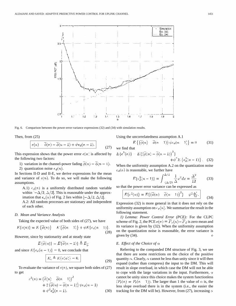
Fig. 6. Comparison between the power-error-variance expressions (32) and (34) with simulation results.
Then, from (25)
(27)
This expression shows that the power error is affected bythe following two factors:
1) variation in the channel-power fading .2) quantization noise .
In Sections II-D and II-E, we derive expressions for the meanand variance of . To do so, we will make the followingassumptions.
A.1) is a uniformly distributed random variablewithin . This is reasonable under the approx-imation that of Fig. 2 lies within .A.2: All random processes are stationary and independentof each other.
D. Mean and Variance Analysis
Taking the expected value of both sides of (27), we have
(28)However, since by stationarity and at steady state
and since , we conclude that
(29)
To evaluate the variance of , we square both sides of (27)to get
(30)
Using the uncorrelatedness assumption A.1
(31)
we find that
(32)
When the uniformity assumption A.2 on the quantization noiseis reasonable, we further have
(33)
so that the power error variance can be expressed as
(34)
Expression (32) is more general in that it does not rely on theuniformity assumption on . We summarize the result in thefollowing statement.
1) Lemma: Power Control Error (PCE):For the CLPCscheme of Fig. 2, the PCE is zero mean andits variance is given by (32). When the uniformity assumptionon the quantization noise is reasonable, the error variance isgiven by (34).
E. Effect of the Choice of
Referring to the companded DM structure of Fig. 3, we seethat there are some restrictions on the choice of the positivequantity . Clearly, cannot be less than unity since it will thenexpand (rather than compress) the input to the DM. This willresult in slope overload, in which case the DM will not be ableto cope with the large variations in the input. Furthermore,cannot be unity since this choice makes the system functionless
. The larger than 1 the value of is, theless slope overload there is in the system (i.e., the easier thetracking for the DM will be). However, from (27), increasing

1452 IEEE TRANSACTIONS ON VEHICULAR TECHNOLOGY, VOL. 52, NO. 6, NOVEMBER 2003
Fig. 7. Power-fading prediction.
will increase the power-tracking error, thus putting a limitationon how large can be.
To examine the effect of on the PCE, we choose a cer-tain Doppler frequency3 and generate the correspondingpower-fading signal . We also choose a value for the ex-ponent term and run a simulation implementing the CLPC ofFig. 2. The standard deviation (STD) of the error signalis measured. The values of and are then changed and theSTD is measured again. The result is shown in Fig. 5, whichshows that the optimal choice of lies within the interval [1],[2]. The heavy solid curve indicates the optimal path ofas afunction of .
Fig. 6 shows a comparison between the simulation and ana-lytical results of the PCE standard deviation with 85 Hz.The figure shows two curves associated with (32) and (34).
The theoretical curve from (32) shows a strong match withthe simulation results for 1 2. On the other hand, thetheoretical curve associated with (34) matches the simulationresults only for large enough. Recall that (32) assumes thatthe second moment of the quantization error can be es-timated. On the other hand, (34) relies on the uniformity as-sumption for the quantization error (which is dependent upon
and the amount of slope overload in the DM). These observa-tions support our conclusion that (34) should be used only if theuniformity assumption on is reasonable. Otherwise, (32)gives a more-accurate characterization of system performance.
III. OVERSAMPLED CHANNEL PREDICTION
The CLPC methods that we will propose in the sequel willrequire a prediction for the channel power fading profileIn this section, we propose one method for predicting ,which is based on oversampling the received power variations atthe BS. Then, a normalized least mean squares (NLMS)-basedadaptive predictor is used to estimate the channel fading one stepahead. To do so, we assume that the BS knows the transmittedpower of the MS at each time instant. This assumptionis reasonable in CLPC since the BS can usually recoverfrom the information sent to the MS.
3The Doppler frequencyf is the width of the Doppler power spectrum ofthe wireless channel. The Doppler frequency and the delay spread of the channelare reciprocally related [13].
Fig. 7 shows the structure of the proposed prediction method.The measured received power is divided by toget the power attenuation , i.e.,
(35)
The signal is then up-sampled by a factor of, resultingin , where refers to the oversampling index. This can beachieved by increasing the sampling rate of the received powerand by assuming that the transmission power is constant be-tween two consecutive samples of .
The signal is then passed through a delay, as shown inFig. 7. The delayed samples are fed into an adaptivefilter of order . The output of the adaptive filter is comparedto and the comparison error is fed back to the adaptivefilter for training. The taps of the adaptive filter extract thecorrelation between the fading samples. The tap values are car-ried out and used to adapt the taps of an finite-impulse-response(FIR) filter, as shown in the figure. The input to this FIR filter is
and its output is the prediction of , denoted by. This signal is then down-sampled by the same
factor to produce the required prediction value
(36)
The normalized LMS algorithm [14] is used whereby thetap vector is updated according to the rule
(37)
where the regression vector contains the prior samplesof and the notation denotes the Euclidean norm.The constant is the step size of the adaptive filter andis anarbitrary small positive number.
Theperformanceof thispredictor isdependentuponmany fac-tors, such as the filter type, order, and step size. Furthermore, theoversampling factor plays a useful role in the performance ofthe predictor, since it helps increase the correlation between thesamplesof . It shouldbenoted that increasingwill also in-troduce noise in the measured , resulting in a degradationin performance. This usually sets an upper limit for the choice of
. Through simulations, we found that is an acceptablechoice. Fig. 8 shows an attenuation curve resulting from a

ALDAJANI AND SAYED: ADAPTIVE PREDICTIVE POWER CONTROL FOR UPLINK CHANNEL 1453
Fig. 8. Time response of the channel attenuation and its prediction for a Rayleigh-fading channel.
Fig. 9. Prediction error over time for a Rayleigh-fading channel withf = 50 Hz andU = 1.
Rayleigh-fadingchannel togetherwith itspredictedvalue.
Fig. 9 shows a plot of the prediction error1 1 over time for a Rayleigh-fading channel with
50 Hz, 1, and 1.8. The error decays to40 dB and stays under30 dB for most of the simulation time.
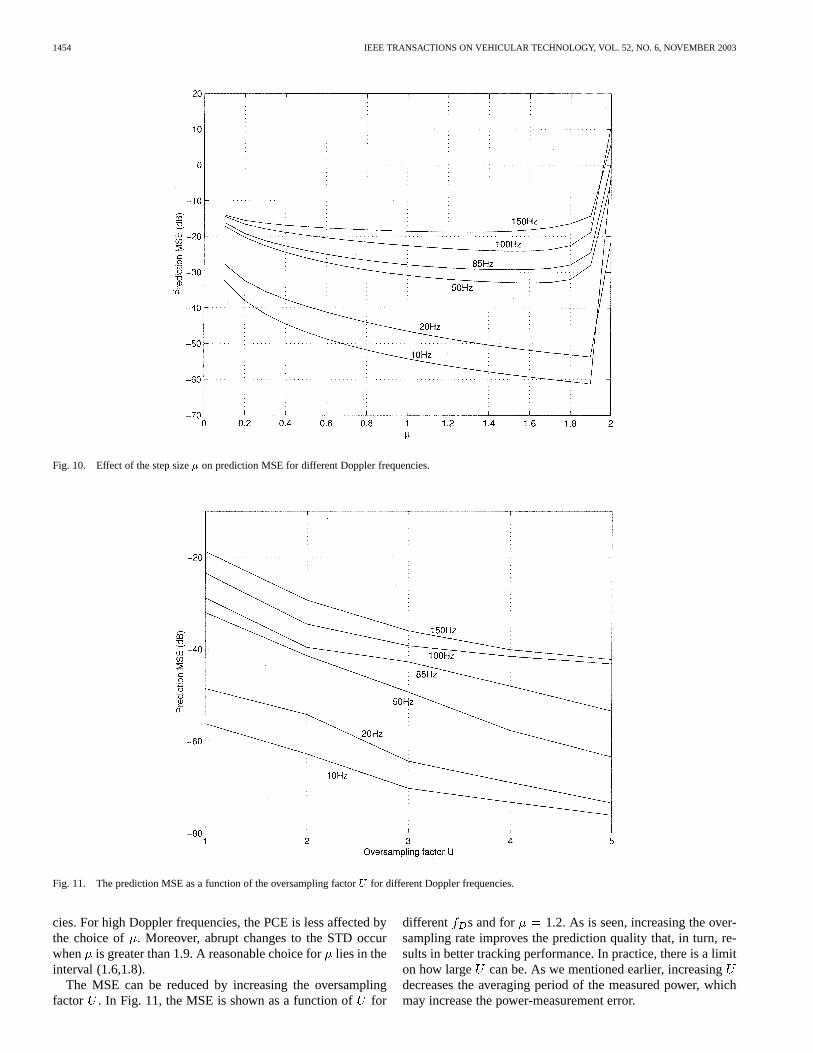
In Fig. 10, we show the prediction mean square error (MSE)versus the step size for different Doppler frequen-
1454 IEEE TRANSACTIONS ON VEHICULAR TECHNOLOGY, VOL. 52, NO. 6, NOVEMBER 2003
Fig. 10. Effect of the step size� on prediction MSE for different Doppler frequencies.
Fig. 11. The prediction MSE as a function of the oversampling factorU for different Doppler frequencies.
cies. For high Doppler frequencies, the PCE is less affected bythe choice of . Moreover, abrupt changes to the STD occurwhen is greater than 1.9. A reasonable choice forlies in theinterval (1.6,1.8).
The MSE can be reduced by increasing the oversamplingfactor . In Fig. 11, the MSE is shown as a function offor
different s and for 1.2. As is seen, increasing the over-sampling rate improves the prediction quality that, in turn, re-sults in better tracking performance. In practice, there is a limiton how large can be. As we mentioned earlier, increasingdecreases the averaging period of the measured power, whichmay increase the power-measurement error.
ALDAJANI AND SAYED: ADAPTIVE PREDICTIVE POWER CONTROL FOR UPLINK CHANNEL 1455
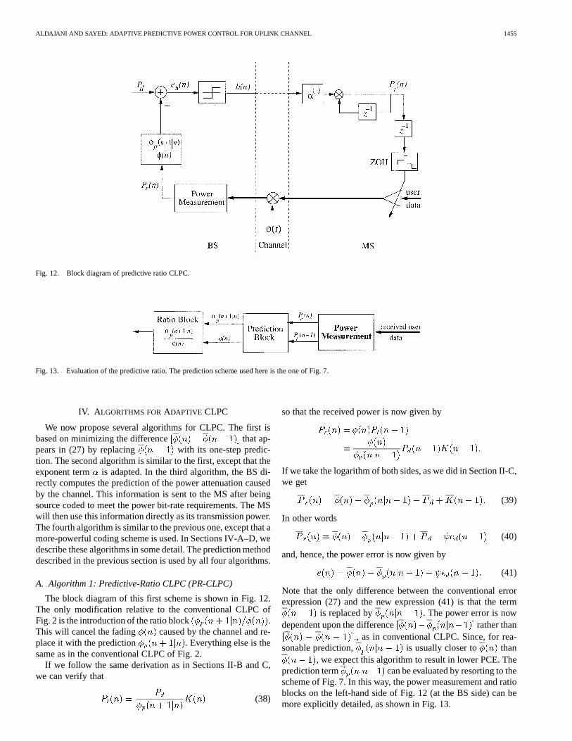
Fig. 12. Block diagram of predictive ratio CLPC.
Fig. 13. Evaluation of the predictive ratio. The prediction scheme used here is the one of Fig. 7.
IV. A LGORITHMS FORADAPTIVE CLPC
We now propose several algorithms for CLPC. The first isbased on minimizing the difference that ap-pears in (27) by replacing with its one-step predic-tion. The second algorithm is similar to the first, except that theexponent term is adapted. In the third algorithm, the BS di-rectly computes the prediction of the power attenuation causedby the channel. This information is sent to the MS after beingsource coded to meet the power bit-rate requirements. The MSwill then use this information directly as its transmission power.The fourth algorithm is similar to the previous one, except that amore-powerful coding scheme is used. In Sections IV-A–D, wedescribe these algorithms in some detail. The prediction methoddescribed in the previous section is used by all four algorithms.
A. Algorithm 1: Predictive-Ratio CLPC (PR-CLPC)
The block diagram of this first scheme is shown in Fig. 12.The only modification relative to the conventional CLPC ofFig. 2 is the introduction of the ratio block .This will cancel the fading caused by the channel and re-place it with the prediction . Everything else is thesame as in the conventional CLPC of Fig. 2.
If we follow the same derivation as in Sections II-B and C,we can verify that
(38)
so that the received power is now given by
If we take the logarithm of both sides, as we did in Section II-C,we get
(39)
In other words
(40)
and, hence, the power error is now given by
(41)
Note that the only difference between the conventional errorexpression (27) and the new expression (41) is that the term
is replaced by . The power error is nowdependent upon the difference rather than
, as in conventional CLPC. Since, for rea-sonable prediction, is usually closer to than
, we expect this algorithm to result in lower PCE. Theprediction term can be evaluated by resorting to thescheme of Fig. 7. In this way, the power measurement and ratioblocks on the left-hand side of Fig. 12 (at the BS side) can bemore explicitly detailed, as shown in Fig. 13.
1456 IEEE TRANSACTIONS ON VEHICULAR TECHNOLOGY, VOL. 52, NO. 6, NOVEMBER 2003
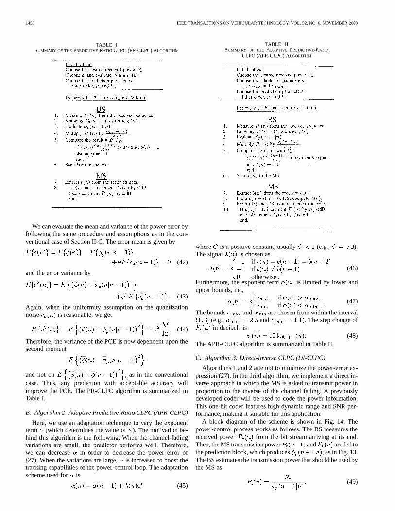
TABLE ISUMMARY OF THE PREDICTIVE-RATIO CLPC (PR-CLPC) ALGORITHM
We can evaluate the mean and variance of the power error byfollowing the same procedure and assumptions as in the con-ventional case of Section II-C. The error mean is given by
(42)
and the error variance by
(43)
Again, when the uniformity assumption on the quantizationnoise is reasonable, we get
(44)
Therefore, the variance of the PCE is now dependent upon thesecond moment
and not on , as in the conventionalcase. Thus, any prediction with acceptable accuracy willimprove the PCE. The PR-CLPC algorithm is summarized inTable I.
B. Algorithm 2: Adaptive Predictive-Ratio CLPC (APR-CLPC)
Here, we use an adaptation technique to vary the exponentterm (which determines the value of). The motivation be-hind this algorithm is the following. When the channel-fadingvariations are small, the predictor performs well. Therefore,we can decrease in order to decrease the power error of(27). When the variations are large,is increased to boost thetracking capabilities of the power-control loop. The adaptationscheme used for is
(45)
TABLE IISUMMARY OF THE ADAPTIVE PREDICTIVE-RATIO
CLPC (APR-CLPC) ALGORITHM
where is a positive constant, usually (e.g., ).The signal is chosen as
ififotherwise .
(46)
Furthermore, the exponent term is limited by lower andupper bounds, i.e.,
ifif
(47)
The bounds and are chosen from within the interval(e.g., and . The step change ofin decibels is
(48)The APR-CLPC algorithm is summarized in Table II.
C. Algorithm 3: Direct-Inverse CLPC (DI-CLPC)
Algorithms 1 and 2 attempt to minimize the power-error ex-pression (27). In the third algorithm, we implement a direct in-verse approach in which the MS is asked to transmit power inproportion to the inverse of the channel fading. A previouslydeveloped coder will be used to code the power information.This one-bit coder features high dynamic range and SNR per-formance, making it suitable for this application.
A block diagram of the scheme is shown in Fig. 14. Thepower-control process works as follows. The BS measures thereceived power from the bit stream arriving at its end.Then, the MS transmission power and are fed tothe prediction block, which produces , as in Fig. 13.The BS estimates the transmission power that should be used bythe MS as
(49)

ALDAJANI AND SAYED: ADAPTIVE PREDICTIVE POWER CONTROL FOR UPLINK CHANNEL 1457
Fig. 14. Block diagram of the direct inverse CLPC algorithm. The prediction scheme of Fig. 7 can be used here.
Fig. 15. Coding scheme used in the DI-CLPC algorithm. (a) Encoder and (b) decoder.
This information is to be transmitted to the MS. Since we arelimited by the power bit rate, should be coded to meetthis rate.
The coding scheme used to transmit could be the adap-tation part of the ADM described in [15], [16]. This coder ex-hibits strong tracking, good stability, and high dynamic range.Fig. 15 shows a block diagram of the coding scheme; the en-coder and decoder are shown in parts a and b, respectively. Theequations describing the dynamics of the coder are
sign
In this algorithm, the term denotes the coding exponent (thesubscript is added to distinguish it from theused in the pre-vious algorithms). The DI-CLPC algorithm is summarized inTable III.
TABLE IIISUMMARY OF THE DIRECT INVERSECLPC (DI-CLPC) ALGORITHM

1458 IEEE TRANSACTIONS ON VEHICULAR TECHNOLOGY, VOL. 52, NO. 6, NOVEMBER 2003
Fig. 16. Coding scheme used in the ADI-CLPC Algorithm.
TABLE IVSUMMARY OF THE ADAPTIVE DIRECT INVERSE
CLPC (ADI-CLPC) ALGORITHM
D. Algorithm 4: Adaptive Direct Inverse CLPC (ADI-CLPC)
In the previous algorithm, the coding constanthas a fixedvalue. However, in order to provide the coder with more freedomto track high variations in the coded transmission power, thecoding constant can be allowed to vary, as shown in Fig. 16.The purpose of adapting is similar to that in the APR-CLPCalgorithm; namely, to cope with large variations in the channelpower fading. Moreover, the same adaptation technique forused in APR-CLPC is adopted here, i.e.,
(50)
where
ififotherwise
(51)
and
ifif
(52)
with typical values , and . TheADI-CLPC algorithm is summarized in Table IV.
TABLE VPOWER-CONTROL ERRORSTD OBTAINED USING CONVENTIONAL CLPC
V. SIMULATIONS
The algorithms developed in this article have been simulatedusing Matlab and Simulink. The following are the simulationparameters used:
• Desired power level : 0 dB;• Power bit rate: 1500 Hz;• Up-sampling factor : 2;• Channel type: frequency-selective multipath Rayleigh
fading with two taps and variable mobile speed.The channel-fading data was obtained using Simulink. The
standard deviation of the PCE is used as a measure of howwell the power-control algorithms achieve the desired receivedpower. The exponent term and the prediction step sizearechosen as 1.3 and 0.8, respectively, unless otherwise specified.The standard deviations of the PCE obtained from conventionalCLPC for different Doppler frequencies are shown in Table Vfor reference.
We start our tests by investigating the effect ofand onthe performance of the PR-CLPC algorithm. Fig. 17 shows theeffect of choosing different on the PCE standard deviation fordifferent values of . Choosing results in best per-formance as indicated by the vertical heavy arrow in the figure.This PCE can be further reduced depending on the choice of theexponent term , as shown in Fig. 18. The optimal PCE changesin a nonlinear fashion with respect to. When the Doppler fre-quency of the mobile unit can be measured, then we can refer toFig. 18 for the optimal choice of. However, if the Doppler fre-quency cannot be measured accurately, then a choice ofseems to be reasonable, as indicated by the vertical arrow in thefigure.
The APR-CLPC algorithm is tested via simulations. Fig. 19shows the STD of the PCE for two different values of the adap-tation constant . The saturation limits for are chosen as

ALDAJANI AND SAYED: ADAPTIVE PREDICTIVE POWER CONTROL FOR UPLINK CHANNEL 1459
Fig. 17. Effect of choosing� on PCE for the PR-CLPC algorithm using� = 1:3.
Fig. 18. Effect of choosing� on PCE for the PR-CLPC algorithm.
and Increasing will improve the per-formance of the CLPC algorithm at high vehicle speeds, but willdegrade it at low speeds. Choosing was found reason-able for all tested applications.
Fig. 20 shows a typical response of the adaptive coding term, used in the ADI-CLPC algorithm as a function of time
with Hz. The mean and variance values for inthis example are 1.22 and 0.02, respectively.

1460 IEEE TRANSACTIONS ON VEHICULAR TECHNOLOGY, VOL. 52, NO. 6, NOVEMBER 2003
Fig. 19. Power errors for the APR-CLPC algorithm for two values of the adaptation constantC.
Fig. 20. A typical response for the exponent term� (n) of the ADI-CLPC algorithm over time for a Rayleigh-fading channel withf = 85 Hz.
Finally, Fig. 21 shows the PCE performance of the PR-CLPC,APR-CLPC, DI-CLPC, and ADI-CLPC. The coding parame-ters and used in the DI-CLPC algorithm are chosen as1E-3 and 1.8, respectively. Moreover, the parameters, ,
for the ADI-CLPC algorithm are set to 0.1, 1.1, and2, respectively. Fig. 21 also includes the performance of the
conventional CLPC and that of an adaptive CLPC developed in[17], for the sake of comparison. The ADI-CLPC demonstratesthe best performance over all other algorithms. Although thepower period is an important parameter that can affect theperformance of the algorithms, only a single value is tested inthis work.

ALDAJANI AND SAYED: ADAPTIVE PREDICTIVE POWER CONTROL FOR UPLINK CHANNEL 1461
Fig. 21. Performance of the developed algorithms compared to conventional CLPC and an adaptive CLPC developed in [15].
VI. CONCLUSION
In this paper, we first explained that conventional CLPC isessentially a companded delta modulator. We then derived anexpression for the PCE in conventional CLPC systems. Thepower error was shown to have zero mean and an expression forthe error variance was derived. Several power-control schemeswere proposed, which attempt to minimize the power-errorvariance. A prediction scheme that is based on oversamplingthe power measurements was used. In simulations, all proposedpower-control schemes showed improved performance over theconventional scheme in terms of minimizing the power-errorvariance.
ACKNOWLEDGMENT
The first author would like to thank King Fahd University ofPetroleum and Minerals for partial support of this work.
REFERENCES
[1] T. Ojanpera and R. Prasad,Wideband CDMA for Third Generation Mo-bile Communications. London, U.K.: Artech House, 1998.
[2] S. Nourizadeh, P. Taaghol, and R. Tafazolli, “A novel closed loop powercontrol for UMTS,” inProc. First Int. Conf. 3G Mobile CommunicationTechnologies, London, U.K., Mar, 2000, pp. 56–59.
[3] W. Xinyu, G. Ling, and L. Guoping, “Adaptive power control on thereverse link for CDMA cellular system,” inProc. Fifth Asia PacificConf. Communications/Fourth Optoelectronics and CommunicationsConf,, vol. 1, Beijing, China, Oct. 1999, pp. 608–611.
[4] S. Park and H. Nam, “DS/CDMA closed-loop power control with adap-tive algorithm,” Electron. Lett., vol. 35, no. 17, pp. 1425–1427, Aug.1999.
[5] M. Sim, E. Gunawan, B. Soong, and C. Soh, “Performance study ofclose-loop power control algorithms for a cellular CDMA system,”IEEETrans. Veh. Technol., vol. 48, pp. 911–921, May 1999.
[6] H. Su and E. Geraniotis, “Adaptive closed-loop power control withquantized feedback and loop filtering,” inProc. IEEE Int. Symp.Personal, Indoor and Mobile Radio Communications, vol. 2, Boston,MA, Sept. 1998, pp. 926–931.
[7] S. Choe, T. Chulajata, H. Kwon, K. Byung-Jin, and S. Hong, “Linearprediction at base station for closed loop power control,” inProc.IEEE Vehicular Technology Conf., vol. 2, Houston, TX, May 1999, pp.1469–1473.
[8] J. Tanskanen, A. Huang, and I. Hartimo, “Predictive power estimators inCDMA closed loop power control,” inProc. IEEE Vehicular TechnologyConf., vol. 2, Ottawa, ON, Canada, May 1998, pp. 1091–1095.
[9] F. Lau and W. Tam, “Intelligent closed-loop power control algorithmin CDMA mobile radio system,”Electron. Lett., vol. 35, no. 10, pp.785–786, May 1999.
[10] A. Abrardo and D. Sennati, “On the analytical evaluation of closed-looppower-control error statistics in DS-CDMA cellular systems,”IEEETrans. Veh. Technol., vol. 49, pp. 2071–80, Nov. 2000.
[11] S. Ariyavisitaluk and L. F. Chang, “Signal and interference statistics ofa CDMA system with feedback power control,”IEEE Trans. Commun.,vol. 41, pp. 1626–1634, Nov. 1993.
[12] M. Aldajani and A. H. Sayed, “A stable structure for delta modulationwith improved performance,” inProc. Int. Conf. Acoustics, Speech, andSignal Processing, vol. 4, Salt Lake City, UT, May 2001, pp. 2621–2624.
[13] V. Garg and J. Wilkes, Principles and Applications ofGSM. Englewood Cliffs, NJ: Prentice-Hall, 1999.
[14] A. H. Sayed,Fundamentals of Adaptive Filtering. New York: Wiley,2003.
[15] M. Aldajani and A. H. Sayed, “An adaptive structure for sigma deltamodulation with improved dynamic range,” inProc. 43rd MidwestSymp. Circuits and Systems, vol. 1, Lansing, MI, Aug. 2000, pp.390–394.
[16] , “Stability and performance analysis of an adaptive sigma deltamodulator,” IEEE Trans. Circuits Syst. II, vol. 48, pp. 233–244, Mar.2001.
[17] C. Lee and C. Steele, “Closed-loop power control in CDMA systems,”Proc. Inst. Elect. Eng. Proc.—Commun., vol. 143, no. 4, pp. 231–239,Aug. 1996.

1462 IEEE TRANSACTIONS ON VEHICULAR TECHNOLOGY, VOL. 52, NO. 6, NOVEMBER 2003
Mansour A. Aldajani (S’96–M’01) received theB.S. and M.S. degrees with first honors in systemsengineering from King Fahd University of Petroleumand Minerals, Dhahran, Saudi Arabia, in 1994 and1996, respectively. He received the Ph.D. degreein electrical engineering from the University ofCalifornia, Los Angeles, in 2001.
He is an Assistant Professor of systems engi-neering at King Fahd University of Petroleum andMinerals. His research interests include signal pro-cessing (source coding, high-resolution sigma–delta
data conversion, and adaptive filtering), digital control, and power control inwireless communication.
Dr. Aldajani is the recipient of the Prince Mohammed Ben Fahd Award forresearch projects in 1994, the Academic Support Activities award in 1995, andthe Department Graduate Student Award in 1996.
Ali H. Sayed (S’90–M’92–SM’99–F’01) receivedthe Ph.D. degree in electrical engineering in 1992from Stanford University, Stanford, CA.
He is Professor and Vice Chairman of ElectricalEngineering at the University of California, Los An-geles (UCLA). He is also the Principal Investigatorof the UCLA Adaptive Systems Laboratory. He is theauthor of the textbookFundamentals of Adaptive Fil-tering(New York: Wiley, 2003) and is the coauthor ofthe research monographIndefinite Quadratic Estima-tion and Control(Philadelphia, PA: SIAM, 1999) and
of the textbookLinear Estimation(Englewood Cliffs, NJ: Prentice-Hall, 2000).He is also coeditor of the volumeFast Reliable Algorithms for Matrices withStructure(Philadelphia, PA: SIAM, 1999). His research interests span severalareas, including adaptive and statistical signal processing, filtering and estima-tion theories, signal processing for communications, interplays between signalprocessing and control methodologies, system theory, and fast algorithms forlarge-scale problems.
Dr. Sayed is a member of the editorial boards of the Society of Industrialand Applied MathmaticsJournal on Matrix Analysis and Its Applications,EURASIP Journal on Signal Processing, and theInternational Journal ofAdaptive Control and Signal Processing. He has served as coeditor of specialissues of the journalLinear Algebra and Its Applications, has contributedseveral articles to engineering and mathematical encyclopedias and handbooks,and has served on the program committees of several international meetings.He has also consulted with industry in the areas of adaptive filtering, adaptiveequalization, and echo cancellation. His work has been awarded severalrecognitions, including a 1996 IEEE Donald G. Fink Award, a 2002 Best PaperAward from the IEEE Signal Processing Society, and two Best Student PaperAwards at international meetings. He serves as Editor-in-Chief of the IEEETRANSACTIONS ONSIGNAL PROCESSING.