Embed Size (px)
Citation preview

R90-917779-5
INTERFACIAL STUDIES OF CHEMICAL VAPORINFILTRATED (CVI) CERAMIC MATRIX
COMPOSITES
(0O00 Prepared by
J. J. Brennan
DTICFINAL REPORT ELECTE
Q Contract N00014-87-C-0699 SMAYL4 1 IJfor
Department of the NavyOffice of Naval Research
Arlington, VA 22217
March 31, 1990
* UNITEDTECHNOLOGIESRESEARCHCENTEREast Hartford, Connecticut 06108
DISTRIBUTION: UNLIMITED
DISTRIBUTION- STAinYA]
u"1"Iftd; g 05 14 8

REPORT DOCUMENTATION PAGE OA l 0"10%owm f Wuq 6~ Wta 00"auw' oe~ffiU = 1% "awu~ to "wOe" - "W OW Yq4W'. ."Guaeq tne ttwm'U fUtW .timm.V UWWW" ""Ong da "Up"Lq8tWiq - Mmm~ ut ii. t 4omomueq V4 u.-tfdC'eo' at""at "f'~uoe, a"t 0~-A Urns orv WmWu WW a.'y aut 0 ubt
1. AGENCY USE OMY (A*.w IVAn*) 2. REPORT OATE 3. REPORT TVPE AND DATES COVERED
I Mar. 31, 1990 Final 8/1/87 - 1/31/904L TITLE AND SUBTMTL 3. FUNDING NUMBERS
Irnterfacial Studies of Chemical Vapor Infiltrated (CVI)Ceramic Matrix Composites C - N00014-87-C-0699
6. AUTHOR(S)
J. J. Brennan
7. PERFRMING ORGANIZArION NAMEL(S) AND0 ADORESS4ES) L. PERFORMING ORGANIZATION
United Technologies Research Center REPOR NUMBEREast Hartford, CT 06108 R90-91 7.779-5
S. SPONSORING i MONITORING AGENCY NAME(S) AND AOORESS(ES) IL. SPONSORING/fMONIT ORING
Office of Naval Research AGENCY REPWR NUM11ER
Arlington, VA 22217
11. SUPPUIMENT NOTES
12a. OISTROUTION /AVALAIUTY STATEMENT 121L OISTRIUUTIN Coot
Unlimited Distribution
13. STRACT (Mammum 200 wav
' 4eobjective of this program was to investigate the fiber/matrix interfacial chemistry in CVI SiC matrixcomposites utilizing Nicalon SiC and Nextel 440 mullite fibers and to determine how this interface influencescomposite properties such as strength, toughness, and environmental stability. The SIC matrix was depositedusing three different reactants; methyldichiorosilane (MOS), methyltrichlorosilane (MTS), and dimethyldichloro-silane (DMDS). The fiber/matrix interface was tailored by means of introducing a carbon, BN, or carbon rich SiCinterfacial layer.
It was found that applying a carbon interfacial layer to either N ICALON or Nextel 440 fibers prior to depositionof SIC resulted in a weakly bonded interface that imparted toughness to a CVI matrix composite through its abilityto deflect matrix cracks. This carbon layer can be applied either deliberately by the decomposition of methane orby utilizing an argon flushing gas in the reactor that apparently interrupted the normal deposition of SIC f rom silaneprecursors and instead allowed carbon to deposit. It was found that this carbon interfacial layer, no matter how itwas deposited, was not oxidatively stable at elevated temperatures, leading to severe degradation of compositeproperties. -3-1
14L SUSJECT TERM 1S. NUMIR OF PAGES
CV! SiC matrix composites, ceramic composite interfaces, NICALON 64and Nextel 440 fiber/ceramic matrix composites, BN fiber coatings ML PM CODE
17. SEO.JUIT CkASSWCA1ON 10. SECURITY CLASSWICArION It. SECURl O.ASSOKlATION m N2. WAMTATION OF ABSTRACTOF REPORT OF THIS PAGE Of ABRSTACY
Uu'classitied I Unclassified I UnclasFcified ULFN73460-O1.ZUO.SSO Stand~ard P~ffl 291 (Rov. 2-69)
**-ftv.U6 of AMAi its 0-
13. Abstract (cont
Attempts to produce an interfacial layer of carbon rich SiC (actually a mixture of carbon and SiC) that, fromearlier work, appeared to act as a relatively oxidatively stable yet weakly bonded interface, were not successful.While this type of material could be obtained in bulk samples utilizing MDS plus methane additions, it could not bereproducibly obtained when deposited in thin coating form on fibers. However, studies that utilized BN coatedNICALON fibers with relatively thin '-1 mm) CVD SiC overcoatings indicated that the BN layer remained intactduring the SiC deposition, resulting in relatively weak bonding between the fiber and the deposited SiC. The RTflexural strength of CVI SiC/NICALON fiber composites with BN interfacial layers was quite high [66 ksi (455 MPa)]with typical composite non-linear fracture behavior. Tests were conducted on these composites in flowing oxygenat temperatures from 5500 to 12000C and showed that no degradation in composite strength occurred up to10000C with only moderate strength loss after 12000C exposure. This was in stark contrast to CVI SiCmatrix/NICALON fiber composites with carbon interfacial layers that exhibited severe strength loss after similarexposures.
Accession For
NTIS GRA&I
DTIC DAB 13Unannounced 0Just if oat ion
By-_Di q.ribut on/
KAvr'tlabillty Codes
TAvail uand/orDist Special
.4 ILw._I
UNITEDTECHNOLOGIESRESEARCHCENTEREast Hartford. Connecticut 06108
R90-917779-5
Interfacial Studies of Chemical VaporInfiltrated (CVI) Ceramic Matrix Composites
FINAL REPORT
Contract N00014-87-C-0699
REPORTED BY,. jJ.,Ke nna'-n
APPROVED BY4.a)z,/K. M. Prewo, Manager of
Materials Sciences
DATE 3/31/9n

TABLE OF CONTENTS
SUMMARY ................................................................................ 1
1. INTRODUCTION ...................................................................... 4
If. BACKGROUND........................................................................ 6
Ill. TECHNICAL DISCUSSION ......................................................... 8A. Materials............................................................................ 8B. Sample Fabrication .................................................................. 8C. CVD SiC on Carbon Substrate Studies (MDS + CH4).............................. 9D. CVD SiC Coated Fiber Studies (MOS + CH4)....................................... 10E. CVD SiC Over BN Coated Fibers.................................................... 11F. CVI SiC Matrix Composites.......................................................... 14
IV. CONCLUSIONS AND RECOMMENDATIONS ................................. 18
V. ACKNOWLEDGEMENTS ....................................... 20
REFERENCES........................................................................... 21
TABLES I - IV............................................................................ 26
FIGURES 1-33

R90-917779-5
SUMMARY
The main objective of this program was to investigate the fiber/matrix interface in chemicallyvapor infiltrated (CVI) composites and to understand how the microstructure and chemistry of thisinterface influence composite properties such as strength, toughness, and environmental
stability. The long range goal of this investigation was to develop a CVI ceramic matrix compositethat combined toughness and strength and could operate under stress in oxidizing conditions totemperatures approaching 13000C. The CVI matrix system studied during the first year of thiscontract consisted of SiC deposited from three different reactant gases; methyldichlorosilane(MDS), methyltrichlorosilane (MTS), and dimethyldichlorosilane (DMDS). The fibers utilized wereNicalon SiC and Nextel 440 mullite. During the second year of the program, the emphasis wasconcentrated on the study of utilizing carbon rich SiC and BN fiber coatings as oxidatively stableyet weakly bonded interfacial layers. The chemistry and microstructure of the fiber/matrixinterfacial region were studied through the use of scanning electron microscopy (SEM) of fracturesurfaces, scanning Auger multiprobe (SAM) analysis of the elemental composition of the interfacefrom depth profiles of fiber surfaces and matrix troughs that lie on composite fracture surfaces,and transmission electron microscopy (TEM) of polished surface replicas and ion beam thinnedfoils.
A number of CVI SiC matrix composites were fabricated and analyzed. It was found thatcomposites utilizing Nicalon or Nextel 440 fibers that contained a thin carbon interfacial layer,whether deliberately or inadvertently deposited, exhibited high toughness and strength due to
the weakly bonded carbon interface's ability to deflect matrix cracks. However, this type ofinterface was not oxidatively stable and, when oxidized, lead to severe degradation of compositeproperties.
From studies of deposited SiC layers on Nicalon and Nextel 440 fibers utilizing MDS and MTSprecursors, it was found that the use of an argon flushing gas in the reactor prior to theintroduction of the reactant gases initially disrupted the deposition of SiC such that a thin carbonlayer formed on the surface of the fibers prior to SiC deposition. While this situation resulted in atough composite structure, the lack of oxidative stability, as mentioned previously, wasundesirable. Overcoating this type of composite structure with CVD SiC to seal the fiber/matrixinterface is practiced, but the likelihood of cracking in the coating is high, especially under stress,so that this approach is not considered to be a long term solution.

R90-917779-5
When hydrogen was used as the reactor flushing gas, no carbon interfacial layer was formed
and the deposited SiC bonded very strongly to both Nicalon and Nextel 440 fibers, resulting inweak and brittle composites. However, the deposited SiC appeared to be more consistent in
composition and contain less oxygen.
From studies of the bulk composition of SiC deposited on carbon plates utilizing MDS, MTS,and DMDS precursors, it was found that both MTS and DMDS could controllably yield
compositions that ranged from very silicon rich to essentially stoichiometric SiC, dAnending on thehydrogen carrier gas to silane flow rate ratios. The utilization of MDS as a precursor to SiC
appeared to yield more consistent depositions with compositions ranging from stoichiometric to
slightly carbon rich SiC. The addition of large amounts of methane (CH 4 ) during the MDSdeposition appeared to yield a product that was even more carbon rich (56-60 at %). Previousresults on a different program indicated that a carbon rich SiC coating on Nicalon fibers (most likely
a mixture of SiC + C) did not appear to bond very well to the fibers. It is likely that a coating of this
composition would exhibit relatively good oxidative stability, especially when compared to the
carbon interfacial layers.
Thus, the emphasis for the second year of this investigation was focused on the feasibility of
utilizing a carbon rich SiC interfacial layer for both Nicalon and Nextel 440 fiber composites
fabricated by CVI. In addition to carbon rich SiC as a weakly bonded, crack deflecting, oxidativelystable interface, the application of a CVD BN coating on the fiber surfaces prior to deposition of
the SiC matrix was studied.
Attempts to produce an interfacial layer of carbon rich SiC (actually a mixture of carbon andSiC) that, from earlier work, appeared to act as a relatively oxidatively stable yet weakly bonded
interface, were not successful. While this type of material could be obtained in bulk samples
utilizing MDS plus methane additions, it could not be reproducibly obtained when deposited inthin coating form on fibers. The reasons for this probably have more to do with the type of gas
management system utilized for this work than with the inherent thermodynamics and kinetics of
the deposition process. If better deposition equipment with accurate flow controls and shorterlines from the evaporator to the reaction chamber were utilized, this approach to interface control
in these types of composites could result in improved properties, especially inherent high
temperature oxidation resistance.
The other approach to obtaining an oxidatively stable yet weakly bonded interface in CVI SiC
matrix composites that was investigated consisted of applying BN coatings to the fibers prior to
deposition of the SiC. Initial studies that utilized BN coated NICALON fibers from Synterials with
2

R90-917779-5
relatively thin (-1 g±m) CVD SiC overcoatings indicated that the BN layer remained intact during the
SiC deposition, although some diffusion of Si and possibly C into the BN appeared to occur,
resulting in relatively weak bonding between the fiber and the deposited SiC. Additional
NICALON fibers that were coated with BN at UTRC were then utilized to produce actual small CVI
SiC composite rings. The RT flexural strength of the resultant composites was quite high [66 ksi
(455 MPa)] with typical composite non-linear fracture behavior. Tests were conducted on these
composites in flowing oxygen at temperatures from 5500 to 12000C and showed that no
degradation in composite strength occurred up to 10000C with only moderate strength loss after
12000C exposure. This is in stark contrast to CVI SiC matrix/NICALON fiber composites with
carbon interfacial layers that exhibited severe strength loss Pfter similar exposures. Humidity
testing also indicated that the BN interfacial layers were stable under this type of environment.
Although the results obtained on this program utilizing the BN interfacial layers can only be
considered preliminary, they are sufficiently promising to warrant additional investigation. In order
to fully explore the potential of this system, it is obvious that further processing studies must be
done to scale up the size of the fabricated composites, as well as comprehensive elevated
temperature mechanical and thermal property measurements.
3

R90-917779-5
I. INTRODUCTION
During the past decade, the interest in ceramic matrix composites for high temperaturestructural applications, especially for use in heat engines, has increased to the point that a largenumber of industrial organizations as well as universities and government laboratories throughoutthe world are actively performing research into a myriad of different systems and differentprocessing procedures for these materials. Among the types of ceramic matrix composites under
investigation are whisker reinforced glasses and glass-ceramics1 as well as whisker reinforced
crystalline ceramics2 "18 , and continuous fiber reinforced ceramics produced by methods that
include hot-pressing of glasses and glass-ceramics 19 "3 3 , sol-gel infiltration and pyrolysis of
ceramics34 , polymer precursor infiltration and pyrolysis3 5 , reactive oxidation of metals3 6 , reactivesintering3 7 , and chemical vapor infiltration (CVI) of silicon based ceramics38 "4 9 .
It has been found in all of the above-mentioned ceramic composites that in order to achievehigh strength ard, in particular, high toughness, the bonding at the fiber/matrix interface must becontrolled such that bonding is strong enough to allow load transfer from the matrix to the fibersunder stress but weak enough so that an advancing matrix crack can be deflected by the fibers. Inaddition, the nature of the fiber/matrix interface must include resistance to oxidation at elevatedtemperature as well as resistance to other environmental effects.
For the past decade, research at United Technologies Research Center (UTRC) in the area ofceramic matrix composites has ce itered on systems based on the reinforcement of glass andglass-ceramic matrices with Nicalon polymer derived SiC fibers. In the past few years, this researchhas concentrated on the study of the fiber/matrix interface and the relationship of the interfacial
chemistry and morphology to the composite mechanical and thermal properties 28 ,3 1 . Thecharacterization of the interfaces in these composites has been accomplished primarily by acombination of scanning electron microscope (SEM) observations of composite fracture surfaces,transmission electron microscope (TEM) replica and thin foil analysis, and scanning Augermicroprobe (SAM) analysis of composite fracture surfaces. This work has enabled a greaterunderstanding to be reached of the reactions that occur and the phases formed in these systemsand has led to the successful development of strong, tough, and oxidatively stable glass-ceramicmatrix/Nicalon fiber composite systems for use to temperatures approaching 10000C. While theattainment of much higher use temperature glass-ceramic matrices has been demonstrated, theinherent formation of a carbon rich interfacial layer between the Nicalon fibers and the glass-ceramic matrices during fabrication make the oxidative stability of these composites difficult to
4

R90-917779-5
achieve in the temperature range of 1000-1300C. Work in this area is being carried out at UTRC,primarily through the application of fiber coatings prior to composite fabrication. However, with the
recent successful development of CVD coatings for carbon/carbon composites at UTRC 5 0 , it was
decided to use the knowledge gained in this area with the previous experience in fiber/matrixinterfacial analysis of glass-ceramic matrix composites and apply them to a somewhat different
class of ceramic matrix composites.
One of the most promising routes to the development of ceramic matrix composites that couldpotentially exhibit use temperatures to 13000C or higher is that of chemical vapor infiltration (CVI)of silicon carbide or silicon nitride into fibrous preforms. Work in this type of ceramic matrix
composite; pioneered by researchers at SEP in France43 , is now being carried out at a number of
irstitutions3 8 "4 9 . Most of this work has concentrated on SiC matrices, since the deposition of
crystalline silicon nitride can only be obtained at temperatures that are higher than the maximumstability temperature of fibers such as Nicalon. While CVI SiC reinforced with carbon or Nicalonfibers is now a commercially available ceramic composite from SEP in France and its licensee,DuPont in the U. S., very little work has been reported on the fiber/matrix interfacial chemistry inthese systems, with the exception of some recent research from Oak Ridge National Lab
(ORNL) 5 1 ,52. Since the nature of the fiber/matrix interface plays such an important role in thestrength, toughness, and oxidative stability of these composites, it was decided to investigate theinterfacial chemistry in the CVI SiC matrix composite systems reinforced with both Nicalon SiC andNextel 440 mullite (3AL20 3 .2SIO 2) fibers, with and without fiber coatings. TEM and SAM
analyses of the fiber/matrix interfacial regions in these systems constituted a major portion of thiswork.
• • m | i5

R90-917779-5
II. BACKGROUND
The use of gaseous precursors as a means of depositing a silicon carbide or silicon nitride
ceramic matrix around arrays of oxide, carbide, and carbon fibers has been under investigation atUTRC at a rather low level of effort for several years. From the results of this preliminary work, it
became obvious that control of the deposition parameters and an understanding of the role of thefiber/matrix interface chemistri would be necessary in order to fabricate in a reproducible manner
composites that exhibited high strength and toughness. It was with this basic goal that the currentONR program was initiated. The first years work under this program (9/87-9/88) was reported in
detail in an annual report5 3 . The highlights from this report are described below.
The CVI matrix system studied during the first year of this contract consisted of SiC deposited
from three different reactant gases; methyldichlorosilane (MDS), methyltrichlorosilane (MTS), and
dimethyldichlorosilane (DMDS). The fibers utilized were Nicalon SiC and Nextel 440 mullite. The
chemistry and microstructure of the fiber/matrix interfacial area were studied through the use ofscanning electron microscopy (SEM) of fracture surfaces, scanning Auger multiprobe (SAM)
analysis of the elemental composition of the interface from depth profiles of fiber surfaces andmatrix troughs that lie on composite fracture surfaces, and transmission electron microscopy
(TEM) of polished surface replicas and ion beam thinned foils.
A number of CVI SiC matrix composites were febricated and analyzed. It was found that
composites utilizing Nicalon or Nextel 440 fibers that contained a thin carbon interfacial layer,whether deliberately or inadvertently deposited, exhibited high toughness and strength due to
the weakly bonded carbon interface's ability to deflect matrix cracks. However, this type ofinterface was found to be oxidatively unstable which, when oxidized, lead to severe degradation
of composite properties.
From studies of deposited SiC layers on Nicalon and Nextel 440 fibers utilizing MDS and MTS
precursors, it was found that the use of an argon flushing gas in the reactor prior to theintroduction of the reactant gases initially disrupted the deposition of SiC such that a thin carbon
layer formed on the surface of the fibers prior to SiC deposition. While this situation resulted in a
tough composite structure, the lack of oxidative stability, as mentioned previously, is undesirable.Overcoating this type of composite structure with CVD SiC to seal the fiber/matrix interface ispracticed, but the likelihood of cracking in the coating is high, especially under stress, so that this
approach is not considered to be a long term solution.
6

R90-917779-5
When hydrogen was used as the reactrr flushing gas, no carbon interfacial layer was formed
and the deposited SiC bonded very strongly to both Nicalon and Nextel 440 fibers, resulting in
weak and brittle composites. However, the deposited SiC appeared to be more consistent in
composition and contain less oxygen.
From studies of the bulk composition of SiC deposited on carbon plates utilizing MDS, MTS,
and DMDS precursors, it was found that both MTS and DMDS could controllably yield
compositions that ranged from very silicon rich to essentially stoichiometric SiC, depending on the
hydrogen carrier gas to silane flow rate ratios. The utilization of MDS as a precursor to SiC
appeared to yield more consistent depositions with compositions ranging from stoichiometric to
slightly carbon rich SiC. The addition o: large amounts of methane (CH 4 ) during the MDS
depositkn appeared to yield a product that was even more carbon rich (56-60 at %). Previous
results on a different program5 4 indicateCl' that a carbon rich SiC coating on Nicalon fibers (most
likely a mixture of SiC + C) did not appear to bond very well to the fibers. t is likely that a coating of
this composition would exhibit relatively good oxidative stability, especially when compared to the
carbon interfacial layers.
Thus, the emphasis for the continuation of this investigation was focused on the feasibility of
utilizing a carbon rich SiC interfacial layer for both NICALON and Nextel 440 fiber composites
fabricated by CVI. In addition to carbon rich SiC as a weakly bonded, 'rack deflecting, oxidatively
stable interface, the application of a CVD BN coating on the fiber surfaces prior to deposition of
the SiC matrix was also studied. BN coatings on Nicalon fibers have been found recently to yield
tough, strong, and relatively oxidatively stable glass-ceramic matrix composites at UTRC.
7

R90-917779-5
Ill. TECHNICAL DISCUSSION
A. Materials
The SiC fiber utilized for this program is that produced by Nippon Carbon Co. in Japan and
distributed in the U. S. by Dow Coming Corp., Midland, Mich., under the trade name "Nicalon".The fiber used for this program is the lower oxygen level "Ceramic Grade". The fibers were
obtained on spools of continuous length (500 m) tows of 500 fibers/tow with an average fiber
diameter of 14 g±m. The average tensile strength and elastic modulus of this fiber, as measured at
UTRC, is 2400 MPa (350 ksi) and 193 GPa (28 x 106 psi), respectively. The mullite fiber (Nextel
440) was obtained from 3M Corp., Minneapolis, Minn. on spools of continuous length tows of 780
fibers/tow. According to 3M data, this fiber has a diameter of 7-1 Iim (somewhat oval shaped), a
tensile strength of 1400-2000 MPa (200-300 ksi), and an elastic modulus of 205-240 GPa (30-35x 106 psi). Some of the deposition runs utilized ATJ carbon plates as the substrate material.
The BN fiber coatings were either deposited in-house or by Synterials, Inc., Herndon, VA.
Both sources of BN coatings utilized the decomposition of boron trichloride plus ammonia at
temperatures of -1000°C for the deposition of BN on the fibers.
Three different silane precursors were utilized during the first year of the program to deposit
SiC. Methlydichlorosilane (MDS), CH 3SiHCI2 , has long been used at UTRC to deposit SiC sinceits high vapor pressure (B.P. - 41.5 0C) has allowed the transference of the saturated carrier to the
reactor over long distances without heated lines. Methytrichlorosilane (MTS), CH 3SiCI3 (B.P.=
66.40C), is used extensively by other researchers to deposit SiC and was also used in this
program along with dimethyldichlorosilane (DMDS), (CH 3)2SiCI2 (B.P.- 70.50C). All three of the
silane precursors were obtained from Alfa Products, Danvers, Mass. During the last phase of the
program as reported here, only MDS was utilized as the SiC precursor, sometimes in combination
with methane (CH 4) as a source of excess carbon.
B. Sample Fabrication
The reactor utilized to deposit the CVD SiC coatings and to form the CVI SIC matrix
composites was described in detail in the previous annual report on this program53 . Basically, thereactant gases are introduced into a hollow quartz reaction cylinder at one end and the exhaust
gases are removed at the other end. If the reaction is being run at reduced pressure, a vacuum
pump is attached to the exhaust line. The reactor has removable water cooled copper plates at
8
R90-917779-5
each end. Pieces of carbon placed on the bottom of the reactor hold a hollow carbon cylindricalsusceptor which is heated by an RF coil. When CVD coating either flat carbon plates or tows offibers, carbon rods are inserted into the center of the susceptor to hold the samples beingcoated. When CVI matrix composites are being fabricated, the fiber tows are wound around asolid carbon cylinder that is placed in the center of the reactor without utilizing the normal hollowcarbon susceptor. Thus, the wound carbon rod is heated directly producing a temperaturegradient from the inside of the fiber winding to the outside. This allows deposition of the SiC tooccur on the inside of the windings first so that the wound tows are not sealed off on the outside.The water cooled RF coil around the reactor also adds to the temperature gradient.
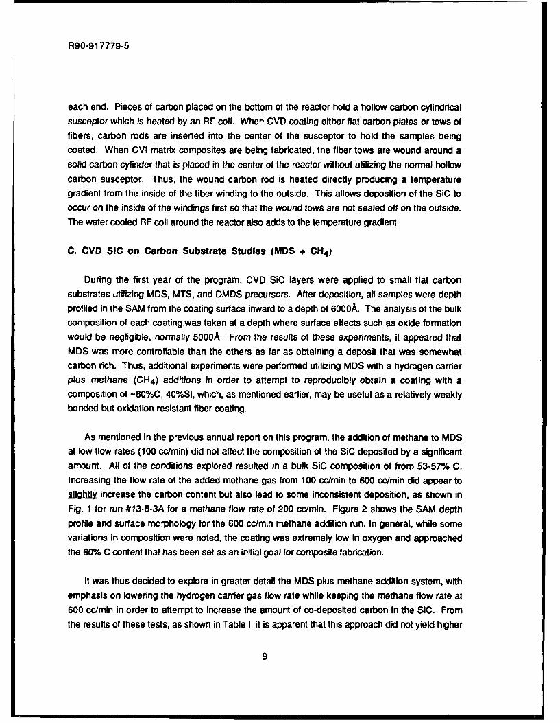
C. CVD SIC on Carbon Substrate Studies (MDS + CH4 )
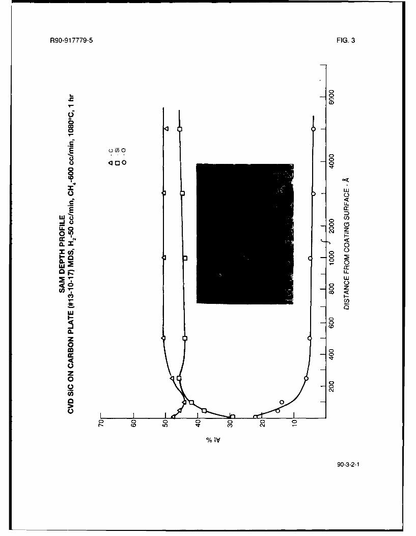
During the first year of the program, CVD SiC layers were applied to small flat carbonsubstrates utilizing MDS, MTS, and DMDS precursors. After deposition, all samples were depthprofiled in the SAM from the coating surface inward to a depth of 6000A. The analysis of the bulkcomposition of each coating.was taken at a depth where surface effects such as oxide formationwould be negligible, normally 5000A. From the results of these experiments, it appeared thatMDS was more controllable than the others as far as obtaining a deposit that was somewhatcarbon rich. Thus, additional experiments were performed utilizing MDS with a hydrogen carrierplus methane (CH4 ) additions in order to attempt to reproducibly obtain a coating with acomposition of -60%C, 400/Si, which, as mentioned earlier, may be useful as a relatively weaklybonded but oxidation resistant fiber coating.
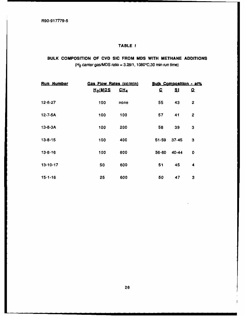
As mentioned in the previous annual report on this program, the addition of methane to MDSat low flow rates (100 cc/min) did not affect the composition of the SiC deposited by a significantamount. All of the conditions explored resulted in a bulk SiC composition of from 53-57% C.Increasing the flow rate of the added methane gas from 100 cc/min to 600 cc/min did appear tosighl increase the carbon content but also lead to some inconsistent deposition, as shown inFig. 1 for run #13-8-3A for a methane flow rate of 200 cc/min. Figure 2 shows the SAM depthprofile and surface mcrphology for the 600 cc/min methane addition run. In general, while somevariations in composition were noted, the coating was extremely low in oxygen and approachedthe 60% C content that has been set as an initial goal for composite fabrication.
It was thus decided to explore in greater detail the MDS plus methane addition system, withemphasis on lowering the hydrogen carrier gas flow rate while keeping the methane flow rate at600 cc/min in order to attempt to increase the amount of co-deposited carbon in the SiC. Fromthe results of these tests, as shown in Table I, it is apparent that this approach did not yield higher
9

R90-917779-5
carbon containing SiC coatings. Lowering the H2/MDS flow rate from 100cc/min to 50 cc/min
actually reduced the amount of excess carbon in the coating, as shown in the SAM depth profile
for run #13-10-17 in Fig. 3. Reducing the H2/MDS flow rate even further, to 25 cc/min, resulted in
even more stoichiometric SiC being deposited, except for an abrupt change in composition nearthe end of the run to almost pure carbon (Fig. 4). The reason for this carbon surface layer
formation is not clear, but may have been caused by the inadvertent closure of the H2/MDS flow
prior to shutting off the methane flow. In any case, it appears that although the composition varies
somewhat, the addition of methane at 600 cc/min to MDS with a hydrogen carrier gas flow rate of100 cc/min produces the optimum amount of excess carbon in the deposited SiC. It was thus
decided to perform additional deposition runs utilizing these conditions on NiCALON and Nextel
fiber tows.
D. CVD SIC Coated Fiber Studies (MDS + CH 4 )
The initial experiment in depositing carbon rich SiC on fibers was done utilizing Nextel 440
mullite fibers, with a run time of 1 hr (Run #13-10-12A). Typical fractured ends of the coated fibers
are shown in Fig. 5. From this figure, it can be seen that the coating deposition was very
nonuniform, with most of the fibers exhibiting a very thick SiC deposit on one side and a very thin
deposit on the opposite side. It is obvious that as the coating deposition became a certain
thickness, the paths for the reactant gases between fibers in close proximity to one another
became blocked by the SiC deposit. There appeared to be some type of interaction between the
coating and the Nextel fibers, however, no SAM analysis of this run was done due to the
thickness of the coating. In general, the bonding between the coating and Nextel fiber appeared
to be quite strong.
An identical coating run (#13-10-13) was performed on NICALON fibers, with rather similar
results, as shown in Fig. 6. In this case, the coating was smoother in appearance and more
uniform in thickness, but still appeared very strongly bonded to the fibers. In order to obtain a SiC
coating that was thin enough to perform SAM analysis on, the above run was repeated on
NICALON fibers for a total run time of 8 minutes, with the other coating parameters supposedly
held constant. The results of this run (#15-12-9A) are shown in Fig. 7 and tabulated in Table II,
along with other runs utilizing fiber substrates. From Fig. 7, it can be seen that the coating
thickness for this run was -2gm, with quite weak bonding between the coating and fibers. From
the high magnification SEM in Fig. 7, it appears that a separate very thin coating exists at the SiC
coating/NICALON fiber interface. Scanning Auger analysis of a coated fiber from this run was
performed, as shown in Fig. 8, and indicated that, while the surface region of the coating (-500A)was somewhat carbon rich, the bulk of the SiC coating appeared to be very close to stoichiometnc
SiC. No indication of a separate thin coating between the SiC coating and the fiber was found,
10

R90-917779-5
however, the analysis steps at this depth into the coating were at 5,o00A sputtering intervals, so athin coating such as that shown in Fig. 7 could easily have been missed.
Another deposition run under the above conditions on NICALON fibers was performedutilizing a run time of only 4 minutes (#15-1-11A). SEM analysis of fractured fiber ends from thisrun, as shown in Fig. 9, again shows a quite weakly bonded coating with a thin interlayer evidentbetween the SiC layer and the fiber surface. From SAM analysis of a coated fiber from this run, asshown in Fig. 10, a very carbon rich (95%) layer of -1 000-2000A in thickness exists between theNICALON fiber and a slightly carbon rich SiC layer of -1 jIm thickness that grades to a very carbonrich surface. This almost pure carbon interlayer undoubtedly also existed in the previous run #15-12-9A and accounts for the weak coating/fiber interfacial bonding observed for these two runs.
An additional deposition run was done utilizing the exact conditions of run #15-1-11A butattempting to make sure that the MDS/H 2 and CH4 flows were introduced into the reactionchamber at the same time and that they were shut off at the same time. In addition, although all ofthe previous runs utilized a hydrogen flush prior to the introduction of the reactant gases, thisprocedure was monitored more closely. The result of this run was that the carbon rich surfacelayer found on the deposited SiC of run #15-1-11 A was eliminated, but the thin carbon interlayer
between the NICALON fiber and the SiC was still present.
At this point, it was decided that with the SiC deposition equipment available to this program,
the controlled deposition of thin carbon rich SiC coatings on small diameter fibers such asNICALON was not possible utilizing the procedure that had been successful in depositing thesetypes of coatings on flat carbon plates. The system of flow control valves was just not accurate orsensitive enough to ensure the proper introduction and mixing of the various precursor gases inthe reaction chamber. It was thus decided to concentrate efforts under this program to thecreation of a weakly bonded but oxidatively stable interface in fiber reinforced CVI SiC matrixcomposites through the use of BN fiber coatings.
E. CVD SIC Over BN Coated Fibers
A series of experiments were performed utilizing BN coated Nextel and NICALON fibers,
overcoated with CVD SiC from H2/MDS with no added CH4 . The results of these experiments aregiven in Table Ill.
11

R90-917779-5
The first experiment was conducted on BN coated Nextel 440 mullite fibers, with the BNcoating being deposited at UTRC. From the work conducted previously53 , it was found that CVDSiC deposited directly on Nextel fibers using a hydrogen flush resulted in a very well bondedSiC/Nextel fiber interface (Fig. 11). When the BN coated Nextel fibers were utilized, the bondingappeared to range from relatively well bonded to rather weakly bonded, as shown in Fig. 12 for run#13-10-11A. There also appears to be a reaction of some sort at the CVI SiC coating/Nextel fiberinterface that may be a result of interaction between the deposited SiC and the BN coating. It isnot clear from Fig. 12 exactly where the BN coating resides.
Figure 13 shows the SAM depth profile obtained from a BN coated Nextel fiber from run #BN-106. It can be seen that the fiber coating is not particularly smooth. The depth profile wasobtained from the relatively smooth region in the center of the pictured fiber and indicates that the-1 Im thick coating is quite boron rich, with a significant amount of carbon in the near-surfaceregion plus from 7-15% oxygen throughout the coating. As will be shown later, BN coatings fromSynterials are also boron rich with significant oxygen content. Figure 14 shows SEM views of thesame BN coated fiber bundle as that utilized for the SAM analysis in Fig. 13, taken from a differentlocation. From this figure, it can be seen that many of the fibers are covered with large globs ofdeposited BN. These large uneven deposits of BN could very well be responsible for theapparent reaction zone seen in Fig. 12 between the fiber and CVD SiC coating. In any case, it wasapparent that the UTRC process to fabricate CVD BN coated fibers was not sufficiently developedto produce the uniformly coated fibers necessary to carry out CVD SiC coating experiments. Itwas thus decided to utilize BN coated fibers from Synterials that had previously been used forglass-ceramic matrix composites and found to be quite uniform in coating thickness andmorphology, at least until the UTRC BN coating process became better developed and capable ofproducing coated fibers of higher quality.
The SAM depth profile and coated fiber appearance for BN coated NICALON fiber lot #88-5-5from Synterials is presented in Fig. 15. This coated fiber lot, which exhibited a measured UTS of360 ksi (2480 MPa), consisted of a quite boron rich coating of --2000A in thickness that containeda significant amount of oxygen (15-20 at%), but essentially no carbon. A small amount of Alimpurity was detected in the BN coating near the fiber surface. The coating thickness was very
uniform with a very smooth surface morphology.
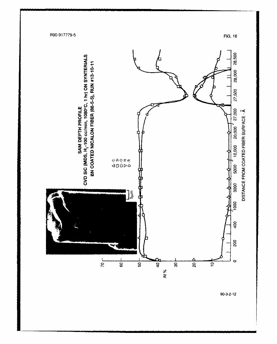
Four CVD SiC coating runs were done utilizing the Synterials BN coated NICALON fibers, asdetailed in Table Il. The first two runs, #13-10-11 and 13-11-7, were done at a CVD SiC run timeof 1 hour utilizing MDS precursor from two different sources. The results of both of these runswere quite similar, as shown in the SAM depth profiles in Figs. 16 and 17, except that the SIC
12

R90-917779-5
coating morphology of run #13-11-7, which used an old tank of MDS, was quite rough andbumpy. All additional runs were done with the MDS source of run #13-10-11, which produced a
smooth SiC fiber coating. The chemistry of the SIC coatings for both of the above runs consistedof relatively stoichiometric SIC with -2/6 oxygen. Both coatings were on the order of 2-2.5 A.m in
thickness. From these SAM depth profiles, it appears that the BN interlayers are present at theSiC/NICALON fiber interface, as evidenced by the relatively weakly bonded nature of the SiC tothe fibers as can be seen in Fig. 16, but that some interdiffusion of Si and C into the BN hasoccurred during the SiC deposition run.
Samples of the CVD SIC over BN coated NICALON fiber (#13-10-11) were subjected to ionbeam thinning and analyzed in the transmission electron microscope (TEM). Figure 18 shows athinned region of the CVD SiC/BNINICALON fiber interface and associated energy dispersive X-ray spectroscopy (EDX) patterns. From this figure, it can be seen that area A, the deposited SIC,
is extremely fine grained or amorphous and gives an EDX pattern showing primarily Si with smallamounts of 0 and C. The small amount of 0 detected correlates well with the SAM analysis, butthe small amount of C detected is an artifact of this analysis method, in that carbon in the presenceof Si is difficult to detect due to absorption oi the carbon X-rays by the Si. This effect is noticed in
area C, the NICALON fiber, as well. Area B, the BN interlayer, indicates the presence of B, N, 0,Si, and also Al. All of these elements (in addition to C) were detected in the BN layer from the
SAM analysis except for the Al. Aluminum was detected from the SAM analysis of the BN coatedNICALON fiber (Fig. 15), however, and, as will be shown later, was detected from the SAManalysis of another CVD SiC/BN/NICALON run (#15-3-22).
Figure 19 shows another thinned region from sample #13-10-11 where it can be seen thatthe deposited SiC initially is very fine grained but then transitions to a somewhat coarser grainedcolumnar structure at a distance of -3000-4000A from the BN interlayer. This is visually veryevident from the dark field micrograph taken from a region somewhat to the right of the bright fieldmicrograph shown in Fig. 19A. It is also evident from the selected area electron diffraction (SAED)patterns shown in Fig. 19, as is the extremely fine grained to amorphous nature of the NICALONfiber and the BN interlayer.
Two additional CVD SIC deposition runs were performed on Synterials BN coated NICALONfiber. The first run (#15-1-18) was done under supposedly identical conditions as run #13-10-11,except the time of deposition was shortened to -3 min in order to obtain a relatively thin SiCcoating. As can be seen from the SAM depth profile of this run (Fig. 20), the thickness of the SiCcoating was indeed thinner (-7000A), but the deposited SiC was very carbon rich, especially atthe beginning and end of the deposition run. The average tensile strength of 20 coated fibers
13

R90-917779-5
from this run was 243 ksi (1680 MPa), indicating some degradation in tensile strength due to the
SiC deposition. The second run (#15-3-22) was also done with a deposition time of -3 min but at
a reduced hydrogen carrier gas flow rate of 25 cc/min. This yielded a thinner SiC coating, as
anticipated, but the composition of this coating was even more carbon rich (Fig. 21) than theprevious run. A small amount of Al was detected in the BN interlayer, as was also found for the as
BN-coated sarrple (Fig. 15).
It is apparent that with the reactor and gas flow controls being used to deposit CVD SiC on
fibers, attempting to deposit thin SiC coatings on fibers by reacting for very short periods of timeresults in uncontrolled stoichiometry of the coating. The reasons for this are not particularly
apparent at this time, but it is obvious that this phenomenon does not occur during longer
deposition runs, as seen from Figs. 16 and 17. No evidence of a carbon rich layer between the
BN interlayer and the SiC coating could be seen in either the SAM depth profile or the TEM thin
foil characterization of run #13-10-11 (Figs. 16, 18, and 19). The sputter rate for the SAM depth
profiling in Fig. 16 was slowed down to 250A increments as the BN layer was approached and no
indication of high carbon content was found, which it surely would have been if indeed the carbon
rich layer was present. It was thus decided to fabricate actual small CVI SiC composites utilizing BN
coated NICALON fibers such that some mechanical property and oxidative stability data could be
obtained and compared to other CVI SiC/NICALON fiber composites with carbon interfacial layers.
F. CVI SIC Matrix Composites
Two CVI SiC matrix composite rings were fabricated utilizing BN coated NICALON fibers. Themethod used to fabricate these rings was described previously, but basically consists of winding
the BN coated NICALON tows around a carbon mandrel. The wound tows were then infiltrated
utilizing the normal H2/M DS ratios and flow rates at a temperature of 1 0800C for a total run time of
100 hrs. The infiltrated composites were then removed from the carbon mandrels, sliced into 0.2"
(0.51 cm) wide rings and then cut into 900 ring segments.
The BN coated NICALON fibers were processed at UTRC in a batch reactor utilizing BCI3 +
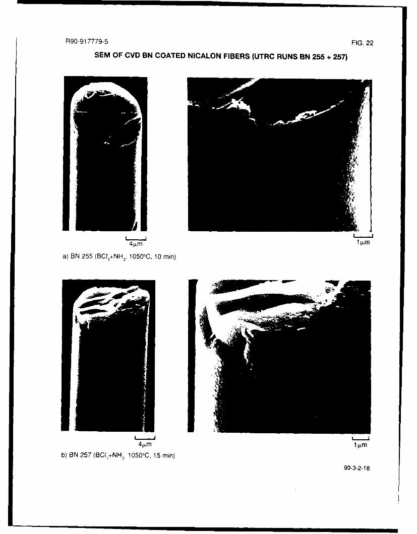
NH 3 at 1 0500C in a 0.2 ton' vacuum for various periods of time. Figure 22 shows examples of two
of these runs (BN 255 and BN 257) that were processed for 10 min and 15 min, respectively. The
BN coatings are quite smooth, with the BN 257 coating being obviously thicker than the BN 255
coating, but some coating thickness variation can be seen in the BN 255 coating. From SEM
evaluation of a number of coated fibers from these and other runs, it was obvious that the BN
coating thickness varied considerably from fiber to fiber within each run and even around the
periphery of a single coated fiber. A continuous BN fiber coater, which is currently under
development at UTRC, should result in much more uniform coating thicknesses.
14

R90-917779-5
The composition of the UTRC BN coatings, while somewhat variable from run to run, wasfound to be significantly closer to stoichiometric BN than the previously utilized Synterials BNcoated fibers, although carbon and oxygen contamination was found to exist. The SAM depthprofile for a BN coated NICALON fiber from run BN 255 is shown in Fig. 23. The rather thick (-1pm) coating on this fiber consists of -40-45% B and N, with -5% 0 and from 5-12/ C. Later BNdeposition runs with a liquid nitrogen cold trap installed between the reaction chamber and thevacuum pump exhibited much reduced levels of carbon.
Both the BN 255 and BN 257 coated NICALON fibers were utilized to fabricate CVI SiCcomposite rings. A polished cross-section parallel to the fiber winding direction for composite#255 is shown in Fig. 24. From this figure, it can be seen that the infiltration of SiC between thewound fiber tows is quite good. It is also obvious that the BN coating on the fibers variesconsiderably in thickness, as previously discussed. Composite #257 was quite similar inappearance except that the average BN interlayer thickness was somewhat greater, althoughvariations in thickness were also present.
Samples of composite #255 were prepared in the form of thin foils and examined in the TEM.Figure 25 shows the interfacial region of this composite and the associated selected area electrondiffraction (SAED) patterns for the three constituents; NICALON fiber, BN interfacial layer, and CVISiC matrix. The apparent gap between the BN and the NICALON fiber appears to be an effect ofpreferential thinning. It was noted that the BN layer and the NICALON fiber thinned much fasterthan the CVI SiC, consequently the SiC matrix was very seldom thin enough for adequatetransmission of electrons. From the SAED patterns and the bright field/dark field pairs shown inFig. 26, t is apparent that the NICALON fiber consists of extremely fine SiC crystallites while theBN layer consists of slightly larger, but still very fine, crystallites of BN. From the EDX patterns ofFig. 26, it is obvious that some Si has diffused into the BN layer, since the BN analysis was taken
from the center of the quite thick (-1 1Lm) layer. Again, some carbon is also present in the BN layerand also, of course, in the CVI SiC and the NICALON fiber, but is next to impossible to detect bythis method in the presence of Si. The transition of the deposited SiC from rather amorphousnext to the BN layer to a fine grained submicron columnar nature farther out into the matrix is
evident in the TEM micrographs of Fig. 27.
As mentioned previously, 900 segments of these composite rings were cut so that mechanicalproperty measurements could be obtained. The 3-pt flexural strength of these cut segments was
obtained from the equations for curved beams prezented in Ref. 55. Figure 28 shows the RTfracture surface of a cut segment of composite #257 that exhibited a flexural strength of 66 ksi(455 MPa). While not a "brushy" type of fracture surface that is often obtained in glass-ceramic
15

R90-917779-5
matrix/NICALON fiber composites, a significant amount of fiber pullout and fiber/matrix debondingcan be seen, with the BN interlayer obviously contributing to this fracture behavior and visible inthe high magnification SEM of Fig. 28. The fracture behavior of this composite is similar to, but notquite as fibrous as, that observed previously5 3 for carbon coated NICALON fiber/CVI SiC matrixcomposites obtained from Oak Ridge National Lab (ORNL)5 6 , as shown in Fig. 29. Both of thesecomposites with either BN or carbon interfacial layers are very different in strength and andfracture behavior when compared to a CVI matrix/NICALON fiber composite from ORNL with nointerfacial layer between the CVI SiC and the NICALON fiber (Fig. 30). It is very apparent that thepresence of a weakly bonded carbon interface or a relatively weakly bonded BN interfacedrastically alters the fracture behavior and increases the strength and toughness of these types ofcomposites.
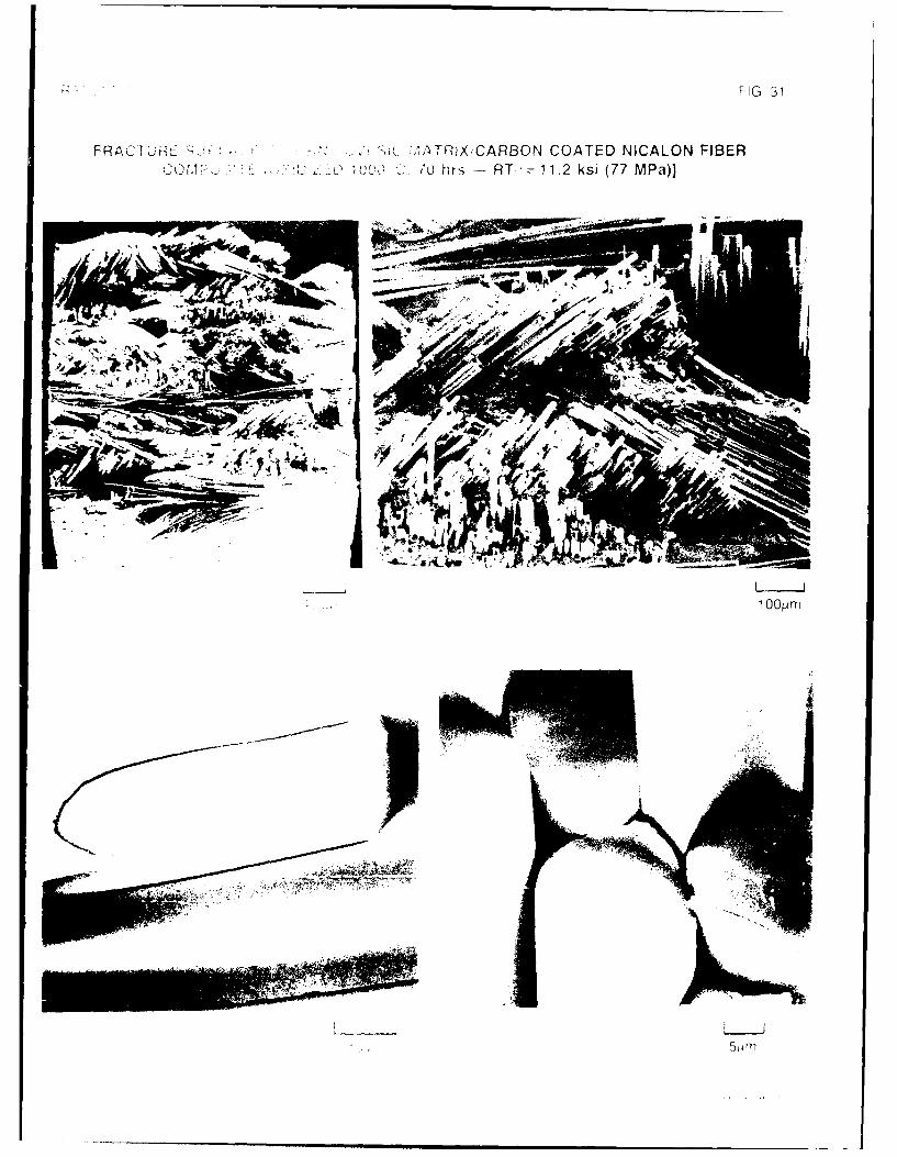
As was discussed in a previous report on this program5 3 , carbon interfaces have also beenfound to result in strong and tough composites in glass-ceramic matrices reinforced withNICALON and other fibers (Dow Coming's HPZ and MPDZ) 5 7 . However, the presence of thistype of interface can lead to severe degradation of composite properties when the composite isexposed to oxidizing environments at elevated temperatures. This has also been found to occurfor CVI SiC matrix composites with carbon interfaces, as shown for an ORNL composite with acarbon interfacial layer that has been exposed to flowing oxygen at 1000°C for 70 hrs (Fig. 31).From this figure, it can be seen that while the fracture surface of this composite is still quite fibrousin appearance, the strength has been reduced drastically to 11.2 ksi (77 MPa) from the previous55 ksi (380 MPa). At high magnification, it is apparent that the carbon layer has oxidized awayleaving a gap between the fibers and matrix, While this gap results in a "tough" fractureappearance, load transfer from the matrix to the fibers cannot occur, thus resulting in a very weakcomposite.
In contrast to the above ORNL composites and previous CVI SiC/NICALON fiber composites
fabricated at UTRC 53 with carbon interfacial layers, the CVI SiC matrix composites (#255 and 257)fabricated with BN interfacial layers exhibited excellent oxidative stability at high temperatures.Cut samples of these composites with no SiC overcoating were subjected to flowing oxygenexposure for 100 hrs at temperatures of 5500, 10000, and 12000C, and then tested at RT inflexure. In addition, a sample was also subjected to humidity testing at 1200F, 100% RH, for 70hrs. This is the standard humidity test for inhibited C/C composites that contain boron additives.From the results of these tests, as shown in Table IV along with the oxidation results from previous
composites with carbon interfacial layers, no degradation in flexural strength for the BN interlayercomposites occurs as a result of humidity testing or oxidative exposure to 1000°C. A relativelysmall decrease in strength (-20%) was observed after oxidative exposure to 12000C. These
16

R90-917779-5
results for the BN interlayer composites are in direct contrast to the very poor results obtained for
the carbon interlayer composites as a result of high temperature oxidative degradation.
Figure 32 compares the crosshead displacement vs stress curves for the CVI SiC matrix/BN
coated NICALON fiber composite #257 in the as-fabricated condition and after exposure to
flowing oxygen at 10000C for 100 hrs. From these curves it can be seen that both composites
exhibit linear behavior to a stress of -200-250 MPa, followed by a non-linear region to ultimate
failure. Even after failure, the composites retain significant load carrying capability. Figure 33
shows the fracture surface of the sample exposed to 1 000°C in flowing oxygen and then tested at
RT. The fracture surface is quite similar to that shown in Fig. 28 for the as-fabricated sample in that
it is not particularly fibrous in nature, but from the high magnification views in Fig. 33 does exhibit
fiber pullout and a considerable amount of fiber/matrix debonding. Evidence of the BN interfacial
layer can be clearly seen at the fiber/matrix interface and is undoubtedly contributing to the
toughness and strength of the composite. In the SEM view of the edge region of the composite
in Fig. 33, it appears that some of the BN interfacial layer has oxidized slightly and is now sticking
to the fibers upon fracture. This was only observed on fibers right next to a cut edge of the
composite and would be expected to contribute to the oxidative stability of this type of composite
through "plugging" of the fiber/matrix interface with a borosilicate glass, thus inhibiting further
oxidation along the interface.
17

R90-917779-5
IV. CONCLUSIONS AND RECOMMENDATIONS
From the results of the studies conducted under this program, certain conclusions can be
made. From the first year's efforts, it was found that applying a carbon interfacial layer to either
NICALON or Nextel 440 fibers prior to deposition of SiC results in a weakly bonded interface thatimparts toughness to a CVI matrix composite through its ability to deflect matrix cracks. This
carbon layer can be applied either deliberately by the decomposition of methane or by utilizing an
argon flushing gas in the reactor that apparently interrupts the normal deposition of SiC fromsilane precursors and instead allows carbon to deposit. It was found that this carbon interfacial
layer, no matter how it was deposited, is not oxidatively stable at elevated temperatures, leading to
severe degradation of composite properties.
Attempts to produce an interfacial layer of carbon rich SiC (actually a mixture of carbon andSiC) that, from earlier work, appeared to act as a relatively oxidatively stable yet weakly bonded
interface, were not successful. While this type of material could be obtained in bulk samples
utilizing MDS plus methane additions, it could not be reproducibly obtained when deposited in
thin coating form on fibers. The reasons for this probably have more to do with the type of gas
management system utilized for this work than with the inherent thermodynamics and kinetics of
the deposition process. If better deposition equipment with accurate flow controls and shorterlines from the evaporator to the reaction chamber were utilized, this approach to interface control
in these types of composites could result in improved properties, especially inherent high
temperature oxidation resistance.
The other approach to obtaining an oxidatively stable yet weakly bonded interface in CVI SiC
matrix composites that was investigated consisted of applying BN coatings to the fibers prior to
deposition of the SiC. Initial studies that utilized BN coated NICALON fibers from Synterials with
relatively thin (-1 gm) CVD SiC overcoatings indicated that the BN layer remained intact during the
SiC deposition, although some diffusion of Si and possibly C into the BN appeared to occur,
resulting in relatively weak bonding between the fiber and the deposited SiC. Additional
NICALON fibers that were coated with BN at UTRC were then utilized to produce actual small CVI
SiC composite rings. The RT flexural strength of the resultant composites was quite high [66 ksi(455 MPa)] with typical composite non-linear fracture behavior. Tests were conducted on these
composites in flowing oxygen at temperatures from 5500 to 12000C and showed that nodegradation in composite strength occurred up to 1 000°C with only moderate strength loss after
1200 0C exposure. This is in stark contrast to CVI SiC matrix/NICALON fiber composites with
carbon interfacial layers that exhibited severe strength loss after similar exposures. Humidity
testing also indicated that the BN interfacial layers were stable under this type of environment.
18

R90-917779-5
All of the CVI SiC matrix composites fabricated at UTRC with BN (and C) interfacial layers wereitested with diamond saw cut surfaces on two sides of the segmented ring samples and a ground
surface on the tensile (concave) surface, so that fiber/matrix interfaces were exposed to theatmosphere. The ORNL samples also were tested with cut surfaces. Although commercial CVISiC matrix/NICALON fiber composites with carbon interfacial layers plus a final CVI SiC overcoat foroxidation protection are being utilized in prototype gas turbine applications, it is apparent that ifthe SiC oxidation protection layer is damaged from impact events, attachment contact stresses, oroverstressing of the part, severe strength degradation could result due to the inherent oxidativeinstability of the carbon interfacial layer. From the results obtained on this program utilizing BNinterfacial layers in CVI SiC matrix/NICALON fiber composites, the catastrophic degradation incomposite properties due to failure of an oxidation protection coating would not occur. Althoughthe results obtained on this program utilizing the BN interfacial layers can only be consideredpreliminary, they are sufficiently promising to warrant additional investigation. In order to fullyexplore the potential of this system, it is obvious that further processing studies must be done toscale up the size of the fabricated composites, as well as comprehensive elevated temperaturemechanical and thermal property measurements.
19
R90-917779-5
V. ACKNOWLEDGEMENTS
The author would like to thank Drs. F. Galasso and R. Veltri of UTRC for their guidance in the
CVI and CVD SiC and BN experiments and to Mr. J. Whittier for his part in the processing of the
samples studied under this program. Thanks also go to Ms. J. Whitehead, Mr. G. McCarthy, and
Mr. D. Delong and Dr. B. Laube for their contributions to the SEM, TEM, and SAM analyses,
respectively, and to Dr. S. G. Fishman of ONR for his sponsorship of the program.
20
R90-917779-5
REFERENCES
1. Gadkaree, K.P. and Chyung, K.: Silicon-Carbide-Whisker-Reinforced Glass and Glass-Ceramic Composites, Am. Cer. Soc. Bull., 65 [21 (1986) 370-376.
2. Becher, P.F. and Wei, G.C.: Toughening Behavior in SiC Whisker Reinforced Alumina,
Comm. Am Cer. Soc., Dec. 1984 C-267-269.
3. Wei, G.C. and Becher, P.F.: Development of SiC Whisker Reinforced Ceramics, Am. Cer.Soc. Bull., 64, (1985) 289-304.
4. Tiegs, T.N. and Becher, P.F.: Whisker Reinforced Ceramic Composites, Proceedings of"Tailoring Multiphase and Composite Ceramics*, 21st. Univ. Conf. on Ceramic Science, Penn
St. Univ. (July 1985) Plenum Press, NY (1986) 639-647.
5. Samanta, S.C. and Musikant, S.: SiC Whiskers-Reinforced Ceramic Matrix Composites, Cer.Engr. and Sci. Proc. (July-Aug 1985) 663-672.
6. Claussen, N. and Petzow, G.: Whisker Reinforced Zirconia Toughened Ceramics,Proceedings of "Tailoring Multiphase and Composite Ceramics", 21 st. Univ. Conf. on CeramicScience, Penn St. Univ. (July 1985) Plenum Press, NY (1986) 649-662.
7. Hermes, E.E. and Mazdiyasni, K.S.: SiC Whisker Reinforced MgAI204 Spinel, Proc. of
NASA/DOD Conf. on Metal, Carbon, and Ceramic Matrix Composites, Cocoa Beach, FL (Jan.
1986) NASA Conf. Publication 2445, 143-155.
8. Shalek, P.D., Petrovic, J.J., Hurley, G.F. and Gac, F.D.: Hot-Pressed SiC Whisker/Si3N4
Matrix Composites, Am. Cer. Soc. Bull. Vol. 65, No. 2 (Feb. 1986) 351-356.
9. Lundberg, R., Kahiman, L., Pompe, R., Carlsson, R. and Warren, R.: SiC Whisker-ReinforcedSi3N4 Composites, Am. Cer. Soc. Bull. [66] 2 (1987) 330-333.
10. Tiegs, T.N. and Becher, P.F.: Sintered A1203-SiC Whisker Composites, ibid, 339-343.
11. Porter, J.R., Lange, F.F. and Chokshi, A.H.: Processing and Creep Performance of SiC
Whisker Reinforced A1203, ibid, 343-347.
21

R90-917779-5
12. Homeny, J., Vaughn, W.L. and Ferber, M.K.: Processing and Mechanical Properties of SiC-
Whisker-A1203 -Matrix Composites, ibid, 333-339.
13. Buljan, S.T., Baldoni, J.G. and Huckabee, M.L.: Si3N4-SiC Composites, ibid, 347-353.
14. Homeny, J. and Vaughn, W.L.: Whisker-Reinforced Ceramic Matrix Composites, MRS Bull.(Oct-Nov 1987) 66-71.
15. Buljan, S.T. and Sarin, V.K.: Silicon Nitride-Based Composites, Composites, Vol. 18, No. 2(Apr 1987) 99-106.
16. Kandori, T., Kobayashi, S., Wada, S. and Kamigaito, 0.: SiC Whisker Reinforced Si3N4Composites. J. Mat. Sci. Let. 6 (1987) 1356-1358.
17. Becher, P.F. and Tiegs, T.N.: Toughening Behavior Involving Multiple Mechanisms: WhiskerReinforcement and Zirconia Toughening, J. Am. Cer. Soc. 70 [9] (1987) 651-654.
18. Akimune, Y., Katano, Y. and Shiehi, Y.: Mechanical Properties and Microstructure of an Air-Annealed SiC-Whisker/Y-TZP Composite, Ad. Cer. Mat. Vol 3, No. 2 (1988) 138-142.
19. Prewo, K.M. and Bacon, J.F.: Proc. of Second Int. Conf. on Composite Materials, TorontoCanada (AIME New York 1978) 64.
20. Prewo, K.M., Bacon, J.F. and Dicus, D.L.: SAMPE 0 (1979) 42.
21. Prewo, K.M.: Development of a New Dimensionally and Thermally Stable Composite,Proceedings of "The Conference on Advanced Composites-Special Topics", (Dec 4-6, 1979)El Segundo CA.
22. Prewo, K.M. and Minford, E.J.: Graphite Fiber Reinforced Thermoplastic Matrix Compositesfor Use at 1000°F, SAMPE J. Vol 21-1 (March 1985).
23. Prewo, K.M.: A Compliant, High Failure Strain Fibre Reinforced Glass Matrix Composite, J.Mat. Sci. 17 (1982) 3549-3563.
24. Bacon, J.F. and Prewo, K.M.: Proc. Second Intl. Conf. on Composite Materials, Toronto
Canada (AIME New York 1978) 753.
22

R90-917779-5
25. Prewo, K.M. and Brennan, J.J.: High Strength Silicon Carbide Fiber-Reinforced Glass MatrixComposites, J. Mat. Sci. 15 (1980) 463-468.
26. Prewo, K.M. and Brennan, J.J.: Silicon Carbide Yam Reinforced Glass Matrix Composites, J.Mat. Sci. 17 (1982) 1201-1206.
27. Brennan, J.J. and Prewo, K.M.: Silicon Carbide Fiber Reinforced Glass-Ceramic MatrixComposites Exhibiting High Strength and Toughness, J. Mat. Sci. 17 (1982) 2371-2383.
28. Brennan, J.J.: Interfacial Characterization of Glass and Glass-Ceramic Matrix/Nicalon SiC FiberComposites, Proc. of the Conf. on Tailoring Multiphase and Composite Ceramics, Penn St.Univ. (July 1985). Materials Science Research Vol 20, Plenum Press, New York (1986) 549-560.
29. Minford, E.J. and Prewo, K.M.: Fatigue Behavior of SiC Fiber Reinforced LAS Glass-Ceramic,
ibid.
30. Prewo, K.M., Brennan, J.J. and Layden, G.K.: Fiber Reinforced Glasses and Glass-Ceramicsfor High Performance Applications, Am. Cer. Soc. Bull. Vol. 65, No. 2 (Feb. 1986).
31. Brennan, J.J.: Interfacial Chemistry and Bonding in Fiber Reinforced Glass and Glass-CeramicMatrix Composites, Proc. of the Conf. on Ceramic Microstructures '86: Role of Interfaces, Univ
of Calif, Berkeley (July 1986) Materials Science Res Vol. 21, Plenum Press, NY (1987) 387-400.
32. Mah, T., Mendiratta, M.G., Katz, A.P., Ruh, R. and Mazdiyasni, K.S.: Room TemperatureMechanical Behavior of Fiber-Reinforced Ceramic-Matrix Composites, J. Am. Cer. Soc. 68 Il](1985) C-27-30.
33. Cooper, R.F. and Chyung, K.: Structure and Chemistry of Fibre-Matrix Interfaces in SiC Fibre-Reinforced Glass-Ceramic Composites: An Electron Microscopy Study, J. Mat. Sci. 22 (1987)3148-3160.
34. Fitzer, E. arid Gadow, R.: Fiber Reinforced Composites Via the SoVGel Route, Materials Sci.Res., Vol. 20, Plenum Press, NY (1986) 571-608.
35. Jamet, J., Spann, J.R., Rice, R.W. Lewis, D. and (;obleuz, W.S.: Ceramic-Fiber CompositeProcessing via Polymer Filled Matrices, Cer. Eng. Sci. Proc. 5[7-8] (1984) 677-694.
23

R90-917779-5
36. Antolin, P.B., Schiroky, G.H., and Andersson, C.A.: Properties of Fiber-Reinforced AluminaMatrix Composites, Ceram. Engr. Sci. Proc., 9 [7-8] (1988) 759-766.
37. Briatt, R.T.: Mechanical Properties -of SiC Fiber-Reinforced Reaction Bonded Si3N4Composites, Mat. Sci. Res., Vol. 20, Tailoring Multiphase and Composite Ceramics, Plenum
Press, NY (1986) 675-686.
38. Warren, J.W.: Fiber and Grain-Reinforced Chemical Vapor Infiltration (CVI) Silicon Carbide
Matrix Composites, Ceram. Eng. Sci. Proc. 5 [7-8] (1985) 684-93.
39. Caputo, A.J. and Lackey, W.J.: Fabrication of Fiber-Reinforced Ceramic Composites byChemical Vapor Infiltration, Cer. Eng. Sci. Proc. 5 [7-81 (1984) 654-67.
40. Caputo, A.J., Lackey, W.J. and Stinton, D.P.: Development of a New, Faster Process for theFabrication of Ceramic Fiber-Reinforced Ceramic Composites by Chemical Vapor Infiltration,
ibid 6 [7-8] (1985) 694-706.
41. Naslain, R. and Langlais, F.: CVI-Processing of Ceramic-Ceramic Composite Materials, Conf
on Tailoring Multiphase and Composite Ceramics, Penn St. Univ. (July 1985) Plenum Press,
NY, 145-164.
42. Fitzer, E. and Gadow, R.: Fiber-Reinforced Silicon Carbide, Am. Cer. Soc. Bull. 65 [2] (1986)326-35.
43. Lamicq, P.J., Bemhart, G.A., Dauchier, M.M. and Mace, J.G.: SiC/SiC Composite Ceramics,ibid, 336-38.
44. Stinton, D.P., Caputo, A.J. and Lowden, R.A.: Synthesis of Fiber-Reinforced SiCComposites by Chemical Vapor Infiltration, ibid, 347-50.
45. Caputo, A.J., Stinton, D.P., Lowden, R.A. and Besmann, T.M.: Fiber-Reinforced SiC
Composites with Improved Mechanical Properties, Am. Cer. Soc. Bull. 66 [2] (1987) 368-72.
46. Moeller, H.H., Long, W.G., Caputo, A.J. and Lowden, R.A.: SiC Fiber Reinforced SiCComposites Using Chemical Vapor Infiltration, SAMPE Quart. (April 1986) 1-4.
24
R90-917779-5
47. Colmet, R., Lhermitte-Sebire, I. and Naslain, R.: Alumina Fiber/Alumina Matrix CompositesPrepared by a CVI Technique, Adv. Cer. Mat. 1 [2] (1986) 185-191.
48. Stinton, D.P., Besmann, T.M. and Lowden, R.A.: Advanced Ceramics by Chemical VaporDeposition Techniques, Am. Cer. Soc. Bull. 67 [21 (1988) 350-356.
49. Lackey, W.J.: Review, Status, and Future of the Chemical Vapor Infiltration Process forFabrication of Fiber-Reinforced Ceramic Composites, Ceram. Engr. Sci. Proc., 10 [7-8],(1989) 577-584.
50. Strife, J.R. and Sheehan, J.E.: Ceramic Coatings for Carbn-Carbon Composites, Am. Cer.Soc. Bull. 67 [2] (1988) 369-374.
51. Lowden, R.A. and Stinton, D.P.: Interface Modification in Nicalon/SiC Composites, Ceram.Engr. Sci. Proc., 9 [7-8] (1988) 705-722.
52. Lowden, R.A.: Characterization and Control of the Fiber-Matrix Interface in Ceramic MatrixComposites, ORNL Report TM-11039, March, 1989.
53. Brennan, J.J.: Interfacial Studies of Chemical Vapor Infiltrated (CVI) Ceramic MatrixComposites, UTRC Annual Report R88-917779-2 on ONR Contract N00014-87-C-0699,Oct. 1, 1988.
54. Brennan, J.J.: The Evaluation of Dow Coming Fibers, UTRC Annual Report R86-917103-12on Contract F33615-83-C-5006 (Feb. 1986).
55. Young, W.C.: Roark's Formulas for Stress and Strain: Sixth Edition, Chapter 8-Curved
Beams, McGraw Hill, 1989.
56. Lowden, R.A. (private communication).
57. Brennan, J.J.: Interfacial Characteristics of Glass-Ceramic Matrix/SiC fiber Composites,Proceedings of Interface Science and Engineering '87, Lake Placid, NY (July 1987), Journalde Physique, 49, C5, #10, Oct. 1988, 791-810.
25
R90-91 7779-5
TABLE I
BULK COMPOSITION OF CVD SIC FROM MDS WITH METHANE ADDITIONS(H2 carrier gas/MDS ratio - 3.28/1, 1 0800C,30 min run time)
Run Number Gas Flow Rates (cc/MIni Bulk CoM~gsition - at%
fi2L!&QS 01 a l 9
12-6-27 100 none 55 43 2
12-7-SA 100 100 57 41 2
13-8-3A 100 200 58 39 3
13-8-15 100 400 51-59 37-45 3
13-8-16 100 600 56-60 40-44 0
13-10-17 50 600 51 45 4
15-1-16 25 600 50 47 3
26

R90-91 7779-5
TABLE it
CVD SIC COATED FIBERS (MDS + CH4)-121M MDS = 3.28/1, 10800C, Evap. at 1028 mm, Cond. at 11 OC)
(100 cc/min H2, 600 cc/min CH-4)
Ruin. F.ib@ Run Tim~e Coating Thickness Coating Camp - at%and M[Rbhology_ Q 5 9
13-10-12A Nextel 440 1 hr 0-20 gm, extremely non-uniform - - -
rough, well adhered
13-10-13 NICALON 1 hr 5-10 gm, somewhat non-uniform - - -
quite smooth, very well adhered
15-12-9A NICALON 8 min 2-3 pim, uniform, coating 50-52 46-50 0-3not weii adhered
15-1 -11A NICALON 4min -1plm, uniform, coating not weli 51-90 8-48 0-1adhered, carbon layer between fiberand coating, plus carbon rich surface
27

R90-91 7779-5
TABLE IIl
CVD SIC OVER BN COATED FIBERS(H2IM DS = 3.28/1, 10800C, 100 cc/min H-2)
Run # Fiber B Coatijng SIC Coating Thickness SIC Coating COMR - 81%(time)L and MO[Rholoay -j QQi 9
13-10-11 A Nextel 480 UTRC 3-6 g±m, non-uniform, smooth - - -
(1 Mv (BN-1 06) to rough surf., quite well adhered
13-10-11 NICALON Synterials 2-3 lim, quite smooth and 48-50 45-50 2(1 Mv (88-5-5) uniform, not well adhered
13-11-7 2 gj.m, uniform thickness, 48 51 10lhM bumpy surface
15-1-18 7000A. uniform thickness, smooth 54-92 10-40 2-6(3 min) surface, moderate adherence,
carbon rich interlayer and surface
15-3-22 2000-3000A, moderate adherence, 66-85 10-30 1-3(3 min) high Carbon content, H2 -25 cc/mmn
28

R90-91 7779-5
TABLE IV
EFFECT OF FIBER COATINGS AND OXIDATION ON THE RT FLEXURALSTRENGTH OF CVI SIC MATRIXINICALON FIBER COMPOSITES
So.urg ibe iLLayui Fie EJ oatQina Heat-Treatment RT a - ksl WMal
ORNL plain weave none none 13(90)carbon none 55 (380)
1 0000C, 70 hrs, 02 11(76)
UTRO wound tow carbon none 30 (207)a1000
0C,120hrs, 02 16(110)
UJTRC wound tow BN none 66 (455)120-F, 100% RH, 70 hrs 64 (441)
55011C, 100 hrs, 02 64 (441)I iOOOOC, 100 hi's, 02 68 (469)
a a12000C, 100 hi's, 02 52 (358)
29

R90-91 7779-5 FIG. 1
E
E C>OO~I0-
o Co00
0 0 X A
0 o
cm 0w <
U,--Cc
oww
ci 0
or
0: U-CL C-4 wWZ 0o z
I-
w
0C. 0z0
04 -0
z0
C 0)
co I-C O Y -
88-9-36-47

R90-91 7779-5 FIG. 2
0D
uj -0 o -0
U<01
0
011 0
oc
00
zz00Q C 0
cl~>w
LO CO00
0 8- -3 -4
R90-91 7779-5 FIG. 3
01.. 0
C
0 n
1C)
400 C0
o
u.J
cc <LL
LL C C z0 C~0
<0
0U
C) )00
AU))
0 00'I
00 0 00cc c~ CC)
% z
9030-

R90-91 7779-5 FIG. 4
C n 0 C
- 44
0<0
ce)
oo
U-
0) M
z
cc 0
0
LU U-a w
C) z
C,,C-
0
z
0 C
0
0D C) C) C)- CD U C C) C'J
% l
90-3-2-2

R90-91 7779-5 FIG. 5
SEM OF CVD SiC ON NEXTEL 440 FIBERS (RUN #13-10-12A)
(MDS, H2-100 cc/min, CH4 -600 cc/min, 10800C, I hr)
L-j
90-3-2-3

R90-91 7779-5 FIG. 6
SEM OF CVD SIC ON NICALON FIBERS (RUN #13-10-13)
(MDS, H2-cc/min, CH 4-600 cc/min, 10800C, 1 hr)
Lm90-3-2-4

R90-917779-5 SEM OF CVD SiC ON NICALON FIBERS (RUN #15-12-9A) FIG. 7(MDS, H 2-100 cc/min, CH 4-600 cc/min, 10800C, 8min)
90-3-2-5

R90-91 7779-5 FIG. 8
400)
0
co,CF~
E0
cm'
* 0)C0
o C)
4000 <
8N. L±.0 D
0 C40 I-cc -E0
0.10
wLo
LU V- C)00
a 0
z0
00CJ
0 CD
>0
% IV
90-3-2-6

R90-91 7779-5 FIG. 9SEM OF CVD SiC ON NICALON FIBERS (RUN #15-1-11A)
(MIDS, H 2-100 cc/min, CH 4-600 cc/min, 10800C, 4 min)[UTS=137 ksi (945 MPa)]
5pRm
1Rpm90-3-2-7

R90-91 7779-5 FIG. 10
(0
ocJ5m
E o
8 - -
o coA wrc6 o
a~ C)
, 1 0
b~ 0
C>J 0
zr-3U
00 0O
0 C
z00
05 00o(
C0 O 0 - CD D C) CJ
90-3-2-8

R90-91 7779-5 FIG. 11
SEM OF CVD SiC ON NEXTEL 440 FIBERS (#7-10-22) (MDS, 2 hrs, H2 FLUSH)
88-9-36-27

R90-91 7779-5 FIG. 12
SEM CVD SiC ON BN COATED NEXTEL 440 MULLITE FIBERS (RUN #13-10-11A)(MDS, H2-100 cc/min, 10800C, 1 hr)
4[km
1 pm90-3-2-9

R90-91 7779-5 FIG. 13
0 0 0
2: -
2a:
Ino~ LLwU aI.- w0
0LL cr0 L
00
00
U) C
0 0D 0 0 0) 0 0) 0 0 0)
0 0) co r- CD jL 1- C4
88-11-49-15

R90-91 7779-5 FIG. 14
SEM OF BN COATED NEXTEL 480 FIBERS (UTRC RUN #BN-106)
90-3-2-10

R90-91 7779-5 FIG. 15
E0=L0
to0
C0C0
LO
o
'0 oLo Lo
Lb
j 0
.i ootc'oC
00w C )
000
UUC00
w U
z (0U)
00
LA
00
90-3-2-1 1
R90-91 7779-5 FIG. 16
V- 0
wo 0
zZ0 :) a
LU 0L. C)
0- -,- I
E 0 a0 C0
08 w
O C-U C" t
Cn~~ 0 c0~ 0
0 Ui-a:aC
N (0 V3 U-
90-32-1

R90-91 7779-5 FIG. 17
0)
0
0 C0
01 0
C.)z0 0 >
o 0<
LU <I.- e LJ
z c1Ol
-JU)o)C-c0 0
LUNU0 C0 i-
000 <-
a0
v- .LU cr) LL
C; M 0<LoL
4c z> )
O 0
C,
0 0 0 0
C0 C) 0 ) ) C). C-
90-3-2-13

R90-917779-5 FIG. 18
-z
0
0.
z
0o t0 N
z
oO i N
90-32-1

RE? 9' FIG 19
0
z LU-ccc
wLL
z 00 -j
C-)z )
w
o 0c
clc
0
LL
oc
Cc)
-- J
zL
ww
co c
90 q-9-15

R90-91 7779-5 FIG. 20
coi
co
o 0 <
CDU-
ww
0
cc 0 co (0 If L
0 0
903--1

R90-91 7779-5 FIG. 21
E0
0)
00
040
LU
C) <LuO
0 ce)uJ
C
0 0
0o 0
Lo
LJL
zz
Lu
0o~ 07 F
00
0) C)) ( t
80
90-3-2-17
R90-91 7779-5 FIG. 22
SEM OF CVD BN COATED NICALON FIBERS (UTRC RUNS BN 255 +257)
a) BN 255 (80 3 +NH 3, 1050o0, 10 min)
4 tm 1 m
b) BN 257 B C - H,~ 105000, 15 m i)90 3 2 1

R90-91 7779-5 FIG. 23
C)
0t
00Co Cu
oo LU-
OLL occ co 0
CL L0)C
X, Z
400
< 0 L
z C-)
00 It F-C
903--1

R90-91 777-9-5 FIG. 24CROSS-SECTIONS OF CVI SiC MATRIXIBN COATED NICALON
FIBER COMPOSITE #255-2
1 OOpm 50Lm
2O1im 903-2-20

R90-91 7779-5 FIG. 25
TEM/SAED THIN FOIL ANALYSES OF CVI SiC OVER BN COATED NICALON FIBERCOMPOSITE #255 (AS-FABRICATED)
NICALON FIBER (A)
BN INTERFACE (B)
CVI SiC MATRIX (C)
1~m
NICALON FIBER (A) BN INTERFACE (B) CVI SiC MATRIX (C)
90-3-2-21

R90-91 7779-5FI.2
1E
--------------- --
z -
0
z
U) -- ;L
=LL
o . j -z
z0
w IL
w CZ
0z
90-3-2-22

R90-91 7779-5 FIG. 27
1Ew
0
0 0
0
zz
000
uJ
u,
E
LL ~LL
0 CC
C13
ILL
0
C/)
90-3-2-23

R90-91 7779-5 FIG. 28
RT FRACTURE SURFACE OF CVI SiC/BN COATED NICALON FIBER COMPOSITE#257-7-2 [AS-FABRICATED, (T=66 ksi (455 MPa)J
5 LLJ
90-3-2-24

R90-9177795 FIG, 29
FRACTURE SURFACE OF ORNIL CVI SiC MATRIX/CARBON COATED NICALON FIBERCOMPOSITE [RT-z55 ksi (380 MPa)]
--0
1 Opm 5pum
88-9-36-7

R~. nFIG 30
FRACTURE SURFACE OF ORNL CVI SiC MATRIX/NICALON FIBER COMPOSITE(RT( 13 Isi (90 MPa)1
- ~~ ','~.i. ' i~~v4P4~~
JL ~ *. - -
.AN1ll
400L,4 m 1000
44 ~
20p ~ rn
* FIG 31
FRACTWKE~ ~ ~ iTR XlCARBON COATED NICALON FIBERC0M .~i D >7 hrs -RT z 11.2 ksi (77 MPa)]
44
A~~mop!
* .o
00,
1 -pr

R90-91 7779-5 FIG. 32
STRESS VS CROSS-HEAD DISPLACEMENT FOR CVI SiC MATRIXIBN COATED NICALONFIBER COMPOSITE #257
500
450
400-BN-257-7-1 BN-257-7-2
(AFTER 100000C, 100o hrs, 02) (AS-FABRICATED)
350
a- 300
Cl)C') 250Ill
W/ 200
150
100
50
040 0.01 0.02 0.03 0.04 0.05 0.06 0.07 0 0.01 0.02 0.03 0.04 0.05 0.06 0.07
CROSS HEAD POSITION (inches) CROSS HEAD POSITION (INCHES)
90-3-2-25

R90-91 7779-5 FIG. 33
RT FRACTURE SURFACE OF CVI SiC/BN COATED NICALON FIBER COMPOSITE #257-7-1[AFTER I1000 0C, 100 hrs, FLOWING 02-RT (j=68 ksi (469 MPa)J
200pLm
EDGE OF SAMPLE SmCENTER OF SAMPLE m
90-3-2-26

![1 Interfacial Rheology System. 2 Background of Interfacial Rheology Interfacial Shear Stress Interfacial Shear Viscosity = [ ]](https://img.dokumen.tips/doc/110x75/56649d1f5503460f949f3d29/1-interfacial-rheology-system-2-background-of-interfacial-rheology-interfacial.jpg)