Embed Size (px)
Citation preview
Case 1:13-cv-00009-UNA Document 1 Filed 01/02/13 Page 1 of 11 PagelD 1
IN THE UNITED STATES DISTRICT COURTFOR THE DISTRICT OF DELAWARE
INTERDIGITAL COMMUNICATIONS,INC., a Delaware corporation,INTERDIGITAL TECHNOLOGYCORPORATION, a Delaware corporation,IPR LICENSING, INC., a Delaware
corporation, and INTERDIGITALHOLDINGS, INC., a Delaware corporation,
Plaintiffs,
V.
Civil Action No.:
ZTE CORPORATION, a Chinese corporation, JURY TRIAL DEMANDEDand ZTE (USA) INC., a New Jerseycorporation,
Defendants.
COMPLAINT
This is an action for patent infringement. Plaintiffs InterDigital Commimications,
Inc., InterDigital Technology Corporation, IPR Licensing, Inc., and InterDigital Holdings, Inc.
(collectively "InterDigital" or "the Plaintiffs"), through their undersigned counsel, bring this
action against Defendants zrE Corporation and ZTE (USA) Inc. (collectively "ZTE" or the
"Defendants"). In support of this Complaint, InterDigital alleges as follows:
Case 1:13-cv-00009-UNA Document 1 Filed 01/02/13 Page 2 of 11 PagelD 2
THE PARTIES
1. Plaintiff InterDigital Communications, Inc. ("InterDigital Communications") is a
Delaware corporation, having its principal place of business at 781 Third Avenue, King of
Prussia, Pennsylvania 19406.
2. Plaintiff InterDigital Technology Corporation ("InterDigital Technology") is a
Delaware corporation, having its principal place ofbusiness at 200 Bellevue Parkway, Suite 300,
Wilmington, DE 19809.
3. Plaintiff IPR Licensing, Inc. ("IPR Licensing") is a Delaware corporation, having
its principal place ofbusiness at 200 Bellevue Parkway, Suite 300, Wilmington, DE 19809.
4. Plaintiff InterDigital Holdings, Inc. is a Delaware corporation, having its principal
place of business at 200 Bellevue Parkway, Suite 300, Wilmington, DE 19809.1
5. On information and belief, defendant ZTE Corporation is a Chinese corporation
with its principal place ofbusiness at ZTE Plaza, No. 55 Hi-Tech Road South, Hi-Tech Industrial
Park, Nanshan District, Shenzhen, Guangdong Province 518057, China.
6. On information and belief, defendant ZTE (USA) Inc. is a New Jersey corporation
with its principal place of business at 2425 N. Central Expy., Ste. 323, Richardson, TX 75080.
JURISDICTION AND VENUE
7. This is a complaint for patent infringement arising under 35 U.S.C. 271 et seq.
This Court has exclusive subject matter jurisdiction under 28 U.S.C. 1331 and 1338(a).
1 InterDigital Communications, Inc., InterDigital Holdings, Inc., InterDigital TechnologyCorporation, and IPR Licensing, Inc. are subsidiaries of InterDigital, Inc., a Pennsylvaniacorporation.
2
Case 1:13-cv-00009-UNA Document 1 Filed 01/02/13 Page 3 of 11 PagelD 3
8. Venue is proper in this district under 28 U.S.C. 1400(b) because Defendants are
subject to personal jurisdiction in this district and therefore "reside" in this district under 28
U.S.C. 1391(c) and 1400(b). On information and belief, Defendants sell various products and
do business throughout the United States, including within this judicial district.
9. Venue is proper in this judicial district under Title 28 U. S. Code 1391(b), (c),
(d) and 1400(b) because this Court has personal jurisdiction over the Defendants by virtue of the
fact that, inter alia, each defendant has purposefully availed itself of the rights and benefits of
Delaware law, regularly does and solicits business in Delaware, has engaged in continuous and
systematic contact with the State of Delaware, and derives substantial revenue from things used
or consumed in the State of Delaware.
THE PATENTS-IN-SUIT
10. There are three patents at issue in this action: United States Patent Nos.
7, 190,966 ("the '966 patent"), 7,286,847 ("the '847 patent"), and 7,941, 151 ("the '151 patent")
(collectively, 'the Patents-in-Suit").
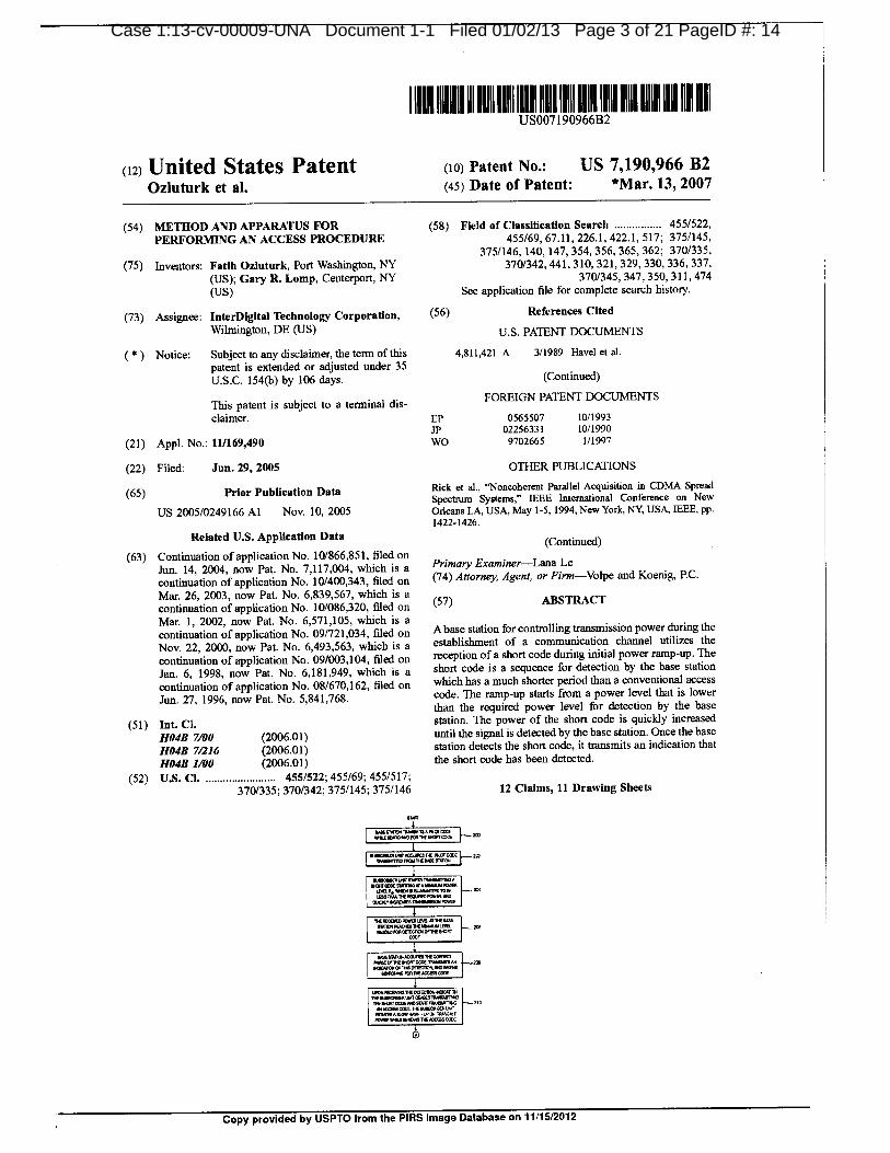
11. The '966 patent is entitled "Method and Apparatus For Performing An Access
Procedure, and issued on March 13, 2007 to inventors Fatih Ozluturk and Gary R. Lomp.
InterDigital Technology owns by assignment the entire right, title, and interest in and to the '966
patent. A true and correct copy of the '966 patent is attached to this Complaint as Exhibit A.
12. The '847 patent is entitled "Method and Apparatus For Performing An Access
Procedure, and issued on October 23, 2007 to inventors Fatih Ozluturk and Gary R. Lomp.
InterDigital Technology owns by assignment the entire right, title, and interest in and to the '847
patent. A true and correct copy of the '847 patent is attached to this Complaint as Exhibit B.
3
Case 1:13-cv-00009-UNA Document 1 Filed 01/02/13 Page 4 of 11 PagelD 4
13. The '151 patent is entitled "Method and System For Providing Channel
Assignment Information Used To Support Uplink And Downlink Channels, and issued on May
10, 2011 to inventors Marian Rudolf, Stephen G. Dick, and Phillip J. Pietraski. InterDigital
Technology owns by assignment the entire right, title, and interest in and to the '151 patent. A
true and correct copy of the '151 patent is attached to this Complaint as Exhibit C.
COUNT I
INFRINGEMENT OF THE '966 PATENT
14. InterDigital repeats each and every allegation of the preceding paragraphs as if set
forth fully herein.
15. In violation of 35 U.S.C. 271, ZTE is now, and has been, directly infringing,
contributorily infringing and/or inducing infringement of, the '966 patent by making, using,
importing, offering for sale, and/or selling wireless devices with 3G capabilities in the United
States, including but not limited to the ZTE 4G Hotspot, Avail, Flash, and JetPack 890L, and
will continue to do so unless enjoined by this Court.
16. On information and belief, ZTE has had actual and/or constructive knowledge of
the '966 patent since before this Complaint was filed. For example, InterDigital asserted related
patents against ZTE in Investigation Number 337-TA-800 before the U.S. International Trade
Commission. In addition, ZTE will receive notice of the '966 patent upon the service of the
Complaint by InterDigital upon ZTE at the addresses referenced herein, concurrently with this
filing.
17. On information and belief, the accused ZTE products are specifically designed to
be used in at least a 3G WCDMA system. Specifically, the accused ZTE products identified by
InterDigital to date that are designed to be used in a UMTS (WCDMA) system are configured to
comply with the Release 99, Release 4, HSDPA, HSUPA, and/or HSPA+ standards. Because
4
Case 1:13-cv-00009-UNA Document 1 Filed 01/02/13 Page 5 of 11 PagelD 5
the accused products are specifically designed to so operate, they have no substantial non-
infringing uses. Accordingly, ZTE contributorily infringes the '966 patent.
18. On information and belief, ZTE, with knowledge of the '966 patent, and without
authority, has actively induced and continues to actively induce infringement by end-users of at
least one claim of the '966 patent, under 35 U.S.C. 271(b), by intentionally inducing the use,
importation, offer for sale, and/or sale of infringing wireless devices with 3G capabilities,
intending to encourage, and in fact encouraging, end-users to directly infringe the '966 patent.
On information and belief, ZTE actively induced infringement by, inter alia, designing and
introducing into the stream of commerce infringing wireless devices with 30 capabilities, and by
publishing manuals and promotional literature describing and instructing in the operation of the
accused devices in an infringing manner and by offering support and technical assistance to its
customers that encourage use of the accused products in ways that infringe the asserted claims.
In addition, ZTE has had actual knowledge of end-users' direct infringement and that ZTE's acts
induced such infringement since at least the date of this filing, when InterDigital provided to
known representatives of ZTE a copy of the complaint (including claim charts) filed in the U.S.
International Trade Commission detailing the allegations of ZTE's infringement of the '966
patent.
19. On information and belief, ZTE has continued its infringement despite having
notice of the '966 patent. ZTE has committed and is committing willful patent infringement.
20. ZTE's past and continuing infringement of the '966 patent has caused monetary
damage and irreparable injury to InterDigital. Unless and until ZTE's infringement is enjoined
by this Court, it will continue to cause monetary damage and irreparable injury to InterDigital.
5
Case 1:13-cv-00009-UNA Document 1 Filed 01/02/13 Page 6 of 11 PagelD 6
COUNT IIINFRINGEMENT OF THE '847 PATENT
21. InterDigital repeats each and every allegation of the preceding paragraphs as if set
forth fully herein.
22. In violation of 35 U.S.C. 271, ZTE is now, and has been, directly infringing,
contributorily infringing and/or inducing infringement of, the '847 patent by making, using,
importing, offering for sale, and/or selling wireless devices with 30 capabilities in the United
States, including but not limited to the ZTE 4G Hotspot, Avail, Flash, and JetPack 890L, and
will continue to do so unless enjoined by this Court.
23. On information and belief, ZTE has had actual and/or constructive knowledge of
the '847 patent since before this Complaint was filed. For example, InterDigital asserted related
patents against ZTE in Investigation Number 337-TA-800 before the U.S. International Trade
Commission. In addition, ZTE will receive notice of the '847 patent upon the service of the
Complaint by InterDigital upon ZTE at the addresses referenced herein, concurrently with this
filing.
24. On information and belief, the accused ZTE products are specifically designed to
be used in at least a 3G WCDMA system. Specifically, the accused ZTE products identified by
InterDigital to date that are designed to be used in a UNITS (WCDMA) system are configured to
comply with the Release 99, Release 4, HSDPA, HSUPA, and/or HSPA+ standards. Because
the accused products are specifically designed to so operate, they have no substantial non-
infringing uses. Accordingly, ZTE contributorily infringes the '847 patent.
25. On information and belief, ZTE, with knowledge of the '847 patent, and without
authority, has actively induced and continues to actively induce infringement by end-users of at
least one claim of the '847 patent, under 35 U.S.C. 271(b), by intentionally inducing the use,
6

Case 1:13-cv-00009-UNA Document 1 Filed 01/02/13 Page 7 of 11 PagelD 7
importation, offer for sale, and/or sale of infringing wireless devices with 3G capabilities,
intending to encourage, and in fact encouraging, end-users to directly infringe the '847 patent.
On information and belief, ZTE actively induced infringement by, inter alia, designing and
introducing into the stream of commerce infringing wireless devices with 3G capabilities, and by
publishing manuals and promotional literature describing and instructing in the operation of the
accused devices in an infringing manner and by offering support and technical assistance to its
customers that encourage use of the accused products in ways that infringe the asserted claims.
In addition, ZTE has had actual knowledge of end-users' direct infringement and that ZTE's acts
induced such infringement since at least the date of this filing, when InterDigital provided to
known representatives of Z IE a copy of the complaint (including claim charts) filed in the U.S.
International Trade Commission detailing the allegations of ZTE's infringement of the '847
patent.
26. On information and belief, ZTE has continued its infringement despite having
notice of the '847 patent. ZTE has committed and is committing willful patent infringement.
27. ZTE's past and continuing infringement of the '847 patent has caused monetary
damage and irreparable injury to InterDigital. Unless and until ZTE's infringement is enjoined
by this Court, it will continue to cause monetary damage and irreparable injury to InterDigital.
COUNT HIINFRINGEMENT OF THE '151 PATENT
28. InterDigital repeats each and every allegation of the preceding paragraphs as if
fully set forth herein.
29. In violation of 35 U.S.C. 271, ZTE is now, and has been, directly infringing,
contributorily infringing and/or inducing infringement of, the '151 patent by manufacturing,
using, importing, offering for sale, and/or selling wireless devices with 4G capabilities in the
7
Case 1:13-cv-00009-UNA Document 1 Filed 01/02/13 Page 8 of 11 PagelD 8
United States, including but not limited to the Flash and JetPack 890L, and will continue to do so
unless enjoined by this Court.
30. On information and belief, ZTE has had actual and/or constructive knowledge of
the '151 patent since before this Complaint was filed. In addition, ZTE will receive notice of the
'151 patent upon the service of the Complaint by InterDigital upon ZTE at the addresses
referenced herein, concurrently with this filing.
31. The accused ZTE products are specifically designed to be used in at least a 4G
wireless communications system. Specifically, the accused ZTE products identified by
InterDigital to date that are designed to be used in a 4G wireless communications system are
configured to comply with the LTE (Long Term Evolution) standard. Because the accused
products are specifically designed to so operate, they have no substantial non-infringing uses.
Accordingly, ZTE contributorily infringes the '151 patent.
32. On information and belief, ZTE, with knowledge of the '151 patent, and without
authority, has actively induced and continues to actively induce infringement by end-users of at
least one claim of the '151 patent, under 35 U.S.C. 271(b), by intentionally inducing the use,
importation, offer for sale, and/or sale of infringing wireless devices with 4G capabilities,
intending to encourage, and in fact encouraging, end-users to directly infringe the '151 patent.
On information and belief, ZTE actively induced infringement by, inter alia, designing and
introducing into the stream of commerce infringing wireless devices with 4G capabilities, and by
publishing manuals and promotional literature describing and instructing in the operation of the
accused devices in an infringing manner and by offering support and technical assistance to its
customers that encourage use of the accused products in ways that infringe the asserted claims.
In addition, ZTE has had actual knowledge of end-users' direct infringement and that ZTE's acts
8

Case 1:13-cv-00009-UNA Document 1 Filed 01/02/13 Page 9 of 11 PagelD 9
induced such infringement since at least the date of this filing, when InterDigital provided to
known representatives of ZTE a copy of the complaint (including claim charts) filed in the U.S.
International Trade Commission detailing the allegations of ZTE's infringement of the '151
patent.
33. On information and belief, ZTE has continued its infringement despite having
notice of the '151 patent. ZTE has committed and is committing willful patent infringement.
34. ZTE's past and continuing infringement of the '151 patent has caused monetary
damage and irreparable injury to InterDigital. Unless and until ZTE's infringement is enjoined
by this Court, it will continue to cause monetary damage and irreparable injury to InterDigital.
JURY DEMAND
35. InterDigital demands a jury trial as to all issues that are triable by a jury in this
action.
PRAYER FOR RELIEF
36. WHEREFORE, InterDigital respectfully requests that this Court enter judgment
against the Defendants as follows:
(a) That Defendants are liable for infringement, contributing to the infringement,
and/or inducing the infringement of one or more claims of the Patents-in-Suit, as alleged herein;
(b) That the Defendants and their parents, subsidiaries, affiliates, successors,
predecessors, assigns, and the officers, directors, agents, servants and employees of each of the
foregoing, customers and/or licensees and those persons acting in concert or participation with
any of them, are preliminarily and permanently enjoined and resfrained from continued
infringement, including but not limited to using, making, importing, offering for sale and/or
selling products that infringe, and from contributorily and/or inducing the infringement of the
Patents-in-Suit prior to their expiration, including any extensions;
9
Case 1:13-cv-00009-UNA Document 1 Filed 01/02/13 Page 10 of 11 PagelD 10
(e) An Order directing Defendants to file with this Court and serve upon Plaintiffs'
counsel within 30 days after the entry of the Order of injunction a report setting forth the manner
and form in which Defendants have complied with the injunction;
(d) An award of damages adequate to compensate InterDigital for the infringement
that has occurred, pursuant to 35 U.S.C. 284, including prejudgment and post-judgment
interest;
(e) An award of treble damages for willful infringement pursuant to 35 U.S.C. 284;
(f) An accounting and/or supplemental damages for all damages occuning after any
discovery cutoff and through the Court's decision regarding the imposition of a permanent
injunction;
An award of attorneys' fees based on this being an exceptional case pursuant to
35 U.S.C. 285, including prejudgment interest on such fees;
(h) Costs and expenses in this action; and
(i) An award of any further relief that this Court deems just and proper.
PROCTOR HEYMAN LLP
/s/ Neal C. BelgamNeal C. Belgam 2721)
[email protected] N. Donimirski (#4701)E-mail: [email protected] Delaware Avenue, Suite 200
Wilmington, Delaware 19801
(302) 472-7300Counselfor Plaintiffs InterDigital Communications,Inc., InterDigital Technology Corporation, IPR
Licensing, Inc., and InterDigital Holdings, Inc.
10

Case 1:13-cv-00009-UNA Document 1 Filed 01/02/13 Page 11 of 11 PagelD 11
OF COUNSEL:
LATHAM & WATKINS LLPRon E. ShulmanE-mail: [email protected] A. LadraE-mail: [email protected] Scott DriveMenlo Park, CA 94025
(650) 328-4600
LATHAM & WATKINS LLP
Maximilian A. GrantE-mail: [email protected] C. ReiserE-mail: [email protected] Eleventh Street, N.W., Ste. 1000
Washington, DC 20004
(202) 637-2200
WILSON SONSINIGOODRICH & ROSATIDavid S. SteuerE-mail: [email protected] B. LevinE-mail: [email protected] L. ReesE-mail: [email protected] Page Mill RoadPalo Alto, CA 94304
(650) 493-9300
Dated: January 2, 2013
11

EXHIBIT A
Case 1:13-cv-00009-UNA Document 1-1 Filed 01/02/13 Page 1 of 21 PageID #: 12

Case 1:13-cv-00009-UNA Document 1-1 Filed 01/02/13 Page 2 of 21 PageID #: 13
Case 1:13-cv-00009-UNA Document 1-1 Filed 01/02/13 Page 3 of 21 PageID #: 14

Case 1:13-cv-00009-UNA Document 1-1 Filed 01/02/13 Page 4 of 21 PageID #: 15
Case 1:13-cv-00009-UNA Document 1-1 Filed 01/02/13 Page 5 of 21 PageID #: 16
Case 1:13-cv-00009-UNA Document 1-1 Filed 01/02/13 Page 6 of 21 PageID #: 17
Case 1:13-cv-00009-UNA Document 1-1 Filed 01/02/13 Page 7 of 21 PageID #: 18

Case 1:13-cv-00009-UNA Document 1-1 Filed 01/02/13 Page 8 of 21 PageID #: 19

Case 1:13-cv-00009-UNA Document 1-1 Filed 01/02/13 Page 9 of 21 PageID #: 20
Case 1:13-cv-00009-UNA Document 1-1 Filed 01/02/13 Page 10 of 21 PageID #: 21
Case 1:13-cv-00009-UNA Document 1-1 Filed 01/02/13 Page 11 of 21 PageID #: 22

Case 1:13-cv-00009-UNA Document 1-1 Filed 01/02/13 Page 12 of 21 PageID #: 23
Case 1:13-cv-00009-UNA Document 1-1 Filed 01/02/13 Page 13 of 21 PageID #: 24
Case 1:13-cv-00009-UNA Document 1-1 Filed 01/02/13 Page 14 of 21 PageID #: 25
Case 1:13-cv-00009-UNA Document 1-1 Filed 01/02/13 Page 15 of 21 PageID #: 26
Case 1:13-cv-00009-UNA Document 1-1 Filed 01/02/13 Page 16 of 21 PageID #: 27
Case 1:13-cv-00009-UNA Document 1-1 Filed 01/02/13 Page 17 of 21 PageID #: 28

Case 1:13-cv-00009-UNA Document 1-1 Filed 01/02/13 Page 18 of 21 PageID #: 29

Case 1:13-cv-00009-UNA Document 1-1 Filed 01/02/13 Page 19 of 21 PageID #: 30
Case 1:13-cv-00009-UNA Document 1-1 Filed 01/02/13 Page 20 of 21 PageID #: 31

Case 1:13-cv-00009-UNA Document 1-1 Filed 01/02/13 Page 21 of 21 PageID #: 32

Case 1:13-cv-00009-UNA Document 1-2 Filed 01/02/13 Page 1 of 24 PageID 33
EXHIBIT B

ease LE3-cv-uuuu9-uNA uocument 1-2 Hied 01102113 Page 2 01' 24 Pageo 34
--1.74111k"\
1
------1•-kitilltilq_ IP r, ..t.
40403,01 :x" 1 rm 1 1 iii ll I I i-1 -71=ttril16,.k 4z', 1, t
41°.1'.
1111111111;;;111711111,111111111111111.1-1111171011111^III110111111;111EIMMIIIMMIMIIIIIIIIIM0111111111.11111111111111611111M-1111111111 It-43ii.I elliftiliiialtaig-- T,II:rdllInTh
I
"—TIIEIJNITEDSTIONESIOFAMEIRICA.r,3: liktmai,txtlysomE1111ESE; PUESENAIA gMtlik, f_21-12,11;1, -1
7 UNITED STATES DEPARTMENT OF COMMERCE 4I
United States Patent and Trademark Office
11.11 November 16, 2012i 4
THIS IS TO CERTIFY THAT ANNEXED HERETO IS A TRUE COPY FROM 'I; .t
THE RECORDS OF THIS OFFICE OF:
A
4.
AteZ
r
U.S. PATENT: 7,286,847
ISSUE DATE: October 23, 2007
IBy Authority of the
Under Secretary of Commerce for Intellectual Propertyand Director of the United States Patent and Trademark Office
i..;
^'k:4 R. PONDEXTER
Certifying Officer
A\\SS
41,111Alii it%,

F.LE2A24,020B
BOMBSC0020501.en,mans N.
215420 aSWCO200
•70
TOM=82.01..Mell11/0015.11'0000_.../11•511.20.0.500.
COMPBEKRBABBO170/111E007P0591
*BURROS WI
15B
DE712CMINTER BEARCHINGNM MIA11.1ROUND
TP4P DELA,: IOWBEMCB13549011100 EVBflPMSES
INB12.40 OP M2201111.0228
172
1
Case 1:13-cv-00009-UNA Document 1-2 Filed 01/02/13 Page 3 of 24 PagelD 35
1111111111111111111111111111111,11111111841111!11111111111111111111111(12) United States Patent (10) Patent No.: US 7,286,847 B2
Ozluturk et al. (45) Date of Patent: *Oct. 23, 2007
(54) METHOD AND APPARATUS FOR (58) Field of Classification Search 370/335,PERFORMING AN ACCESS PROCEDURE 370/342, 441, 310, 321, 329, 330, 336, 337,
370/345, 347, 350, 311, 474; 455/522, 69,(75) Inventors: Fatih Ozluturk, Port Washington, NY 455/67.11, 226.1, 313-334, 517; 375/145,
(US); Gary R. Lomp, Centerport, NY 375/146, 140, 147, 354, 356, 365
(US) See application file for complete search history.
(73) Assignee: InterDigital Technology Corporation, (56) References Cited
Wilmington, DE (US) U.S. PATENT DOCUMENTS
Notice: Subject to any disclaimer, the term of this 4, 811,421 A 3/1989 Havel et al.
patent is extended or adjusted under 35
U.S.C. 154(b) by 162 days. (Continued)
This patent is subject to a terminal dis- FOREIGN PATENT DOCUMENTS
claimer. EP 0565507 10/1993
(21) Appl. No.: 11/169,425 (Continued)
(22) Filed: Jun. 29, 2005 OTHER PUBLICATIONS
(65) Prior Publication Data Rick et al., "Noncoherent Parallel Acquisition in CDMA SpreadSpectrum Systems, IEEE International Conference on New
US 2005/0254478 Al Nov. 17, 2005 Orleans LA, USA, May 1-5, 1994, New York, NY, USA, IEEE, pp.1422-1426.
Related U.S. Application Data (Continued)(63) Continuation of application No. 10/866,851, filed on
Jun. 14, 2004, now Pat. No. 7, 117,004, which is a Primary Examiner-Lana N. Le
continuation of application No. 10/400,343, filed on (74) Attorney, Agent, or Firm-Volpe & Koenig, P.C.
Mar. 26, 2003, now Pat. No. 6,839,567, which is a ic,
continuation of application No. 10/086,320, filed on k'' ABSTRACT
Mar. 1, 2002, now Pat. No. 6,571, 105, which is a
continuation of application No. 09/721,034, filed onA base station for controlling transmission power during the
Nov. 22, 2000, now Pat. No. 6,493,563, which is a establishment of a communication channel utilizes the
continuation of application No. 09/003, 104, filed on reception of a short code during initial power ramp-up. The
Jan. 6, 1998, now Pat. No. 6, 181,949, which is a short code is a sequence for detection by the base station
continuation of application No. 08/670, 162, filed on which has a much shorter period than a conventional access
Jun. 27, 1996, now Pat. No. 5,841,768. code. The ramp-up starts from a power level that is lower
than the required power level for detection by the base
(51) Int. Cl. station. The power of the short code is quickly increased
H04B 7/00 (2006.01) until the signal is detected by the base station. Once the base
HO4B 71216 (2006.01) station detects the short code, it transmits an indication that
HO4B 1/00 (2006.01) the short code has been detected.
(52) U.S. CL 455/522; 455/69; 455/517;455/313; 370/335; 370/342; 375/145; 375/146 11 Claims, 11 Drawing Sheets
BASE MON suascaminerr
i2000010 PIL01-02a I-v-1'C
020.0ElleROI CABE I__, s,ME STATOR SUBSCRIBER um
1 1C0011122,512 EN.
FOR MOWOBOE I--'52 "..Zamax.L".067orri"-IM. ..5
21114,9107COOER 01011024.W BOMB
CORECI0105504CE01720001,2105.5
111/OILBED
1149611302410101211 111
*MOM
051ECTACCES0 CODE AT 1_,745.CT0,00F
00.10EIMAMACCESS CODECEASE NOREABINO
71122^42 MORMON r 8.1r2420.5., I--155CETECIMOCMCN RIMIIMOVOW 5000.1,20•212221DETECTION 71M00111140 WCE1121
11011171372100 227NER.
cow
160 20-2881114000,0
2017112 8/21.5110,152 1521SYSEWING MEE
WM/4Es
0100.10711K1A02258
Copy provided by USPTO from the PIRS Image Database on 11/15/2012
Case 1:13-cv-00009-UNA Document 1-2 Filed 01/02113 Page 4 of 24 PagelD 36
US 7,286,847 B2Page 2
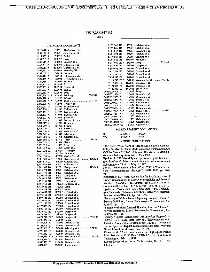
U.S. PATENT DOCUMENTS 6,839,567 B2 1/2005 Ozluturk et al.
6,879,841 B2 4/2005 Ozluturk etal.,5,022,049 A 6/1991 Abrahamson et al. 6,885,652 B1 4/2005 Ozukturk et al.5,056, 109 A 10/1991 Gilhousen et al. 1
6,904,294 B2 6/2005 Ozluturk et al.5, 113, 525 A 5/1992 Andoh 6,940, 840 B2 9/2005 Ozluturk etal.,5, 159,283 A 10/1992 Jensen 6,965,586 B1 11/2005 Maruyama5,235,614 A 8/1993 &Licked et al. 6,983,009 B2* 1/2006 Lomp 375/1405,257,283 A 10/1993 Gilhousen et al. 6,985,467 B2 1/2006 Lomp et al.5,265, 119 A 11/1993 Gilhousen et al. 6,993,001 B1 1/2006 Ozluturk et al.5,267,262 A 11/1993 Wheatley, III 7,020, 111 B2 3/2006 Ozluturk et al.5,297, 162 A 3/1994 Lee et al.
7,072,380 B2 7/2006 Ozluturk et al.5,309,474 A 5/1994 Gilhousen et al.
5,327,455 A 7/1994 De Gaudenzi et al. 7,085, 583 B2 8/2006 Ozluturk et al.
5,347,536 A 9/1994 Meehan 7, 113,793 B2" 9/2006 Veerasamy et al. 375/140
5,353,302 A 10/1994 Bi 7, 117,004 B2 10/2006 Ozluturk et al.
5,353,352 A 10/1994 Dent et al. 7, 123,600 B2 10/2006 Ozluturk et al.
5,373,502 A 12/1994 Turban 7, 126,930 132 10/2006 Pankaj et al.
5,377, 183 A 12/1994 Dent 2002/0036998 Al 3/2002 Lomp5,410,568 A 4/1995 Schilling 370/342 2002/0051434 Al 5/2002 Ozluturk et al.
5,414,728 A 5/1995 Zehavi 2002/0057659 Al 5/2002 Ozluturk et al.
5,430,760 A 7/1995 Dent 375/144 2003/0013447 Al 1/2003 Persson et al.
5,442,625 A 8/1995 Gitlin et al. 2003/0069007 Al 4/2003 Rajaram et al.
5,442,662 A 8/1995 Fukasawa et al. 2004/0252668 Al 12/2004 Ozluturk et al.
5,446,756 A 8/1995 Mallinckrodt 2005/0094604 Al 5/2005 Ozluturk et al.
5,490, 165 A 2/1996 Blakeney et al. 2005/0157679 Al 7/2005 Dulin et al. 370/330
5,528,593 A 6/1996 English et al. 2005/0243897 Al 11/2005 Ozluturk et al.
5,528,623 A 6/1996 Foster et al. 2005/0249165 Al 11/2005 Ozluturk et al.
5,594,718 A 1/1997 Weaver, Jr. et al. 2005/0249166 Al 11/2005 Ozluturk et al.
5,748,687 A 5/1998 Ozluturk 2005/0254478 Al 11/2005 Ozluturk et al.
5,790,959 A 8/1998 Scherer 2005/0265430 Al 12/2005 Ozluturk et al.
5,796,776 A 8/1998 Lomp et al. FOREIGN PATENT DOCUMENTS5,799,010 A 8/1998 Ozluturk et al.
5,828,662 A 10/1998 Jalali et al. JP 02256331 10/1990
5,841,768 A 11/1998 Ozluturk et al. WO 9702665 1/1997
5,898,902 A 4/1999 Tuzov 455/69
5,940,382 A 8/1999 Bairn OTHER PUBLICATIONS
5,991,329 A 11/1999 Lomp et al.
5,991,332 A 11/1999 LompTIA/EIA/IS-95-A, "Mobile Station-Base Station Compat-
et
6,021, 122 A 2/2000 Tiedemannal.
ibility Standard for Dual-Mode Wideband Spread Spectrum6,038,250 A 3/2000 Shou et al. Cellular System", TIA/EIA Interim Standard, Telecommu-
6,049,535 A 4/2000 Ozukturk et al. nications Industry Association, May 1995.
6,085,108 A 7/2000 Knutsson et al. 455/522 Ejzak et al., "Wideband Spread Spectrum Digital Technolo-
6, 157,619 A 12/2000 Ozluturk et al. gies Standards", Telecommunications Industry Association6, 181,949 B1 1/2001 Ozluturk et al. Subcommittee TR-45.5, May 5, 1 997.6,205, 167 B1" 3/2001 Kamgar et al. 375/140 I et al., "Performance of Multi-Code CDMA Wireless Per-6,212, 174 B1 4/2001 Ozluturk et al. sonal Communications Networks", IEEE, 1995, pp. 907-6,215,778 B1 4/2001 Ozluturk et a. 911.6,229,843 B1 5/2001 Lomp et al.6,263,010 B1 7/2001 Naruse et. Krzymien et al., "Rapid Acquisition for Synchronization of
al6,272, 168 B1 8/2001 Lomp et al. Bursty Transmissions in CDMA Microcellular and Personal
6,404,760 B1 6/2002 Holtzman et al. Wireless Systems", IEEE Journal on Selected Areas in
6,456,608 B1 9/2002 Lomp Communications, vol. 14, No. 3, Apr. 1996, pp. 570-579.
6,480,523 B1 11/2002 Rondo Ejzak et al., "Wideband Spread Spectrum Digital Technolo-
6,490,462 B2 12/2002 Ozluturk et al. gies Standards", Telecommunications Industry Association,6,493,563 B1 12/2002 Ozluturk et al. Subcommittee TR-45.5, Apr. 14, 1997.6,507,745 B2 1/2003 Ozluturk et al. "Summary of Multi-Channel Signaling Protocol", Phase IC6,519,474 B2 2/2003 Ozluturk et al.6,571, 105 B2 5/2003 Ozluturk et.
Service Definition, Lucent Technologies Presentation, Apr.
al6,577,876 B2 6/2003 Ozluturk et al. 6, 1997, pp. 1-19.
6,606,503 B2 8/2003 Ozluturk et al. "Summary of Multi-Channel Signaling Protocol", Phase 1C
6,633,600 B2 10/2003 Lomp et al. Service Definition, Lucent Technologies Presentation, Apr.6,674,788 B2 1/2004 Lomp et al. 6, 1997, pp. 1-21.
6,674,791 B2* 1/2004 Lomp et al. 375/146 Knisely, "Lucent Technologies Air Interface Proposal for
6,697,350 B2 2/2004 Lomp CDMA High Speed Data Service", Telecommunications6,707,805 B2 3/2004 Ozluturk et a. Industry Association Subcommittee TR-45.5—Wideband6,721,301 B2 4/2004 Ozluturk et al.6,760,366 B1 7/2004 Wheatley et al. 370/341 Spread Spectrum Digital Technologies Standards, Working
6,778,840 132 8/2004 Ozluturk et.Group III—Physical Layer, Feb. 24, 1997.
al6,788,662 B2 9/2004 Ozluturk et al.Kumar et al., "An Access Scheme for High Speed Packet
6,788,685 Bl* 9/2004 Holtzman et al. 455/69 Data Service on IS-95 Based CDMA", Bell Labs Lucent
6,801,516 B1 10/2004 Lomp et al. Technologies, Feb. 11, 1997.
6,816,473 B2 11/2004 Ozluturk et al. Lucent Presentation, Lucent Technologies, Feb. 21, 1997,6,831,905 B1 12/2004 Lamp et al. pp. 1-24.
Copy provided by USPTO trom the PIRS Image Database on 11/15/2012
Case 1:13-cv-00009-UNA Document 1-2 Filed 01/02/13 Page 5 of 24 PagelD 37
US 7,286,847 B2Page 3
"Packet Data Service Option Standard for Wideband Spread Knisely, "Lucent Technologies Air Interface Proposal for
Spectrum Systems", TIA/EIA Interim Standard, TIA/EIA/ CDMA High Speed Data Service", Telecommunications
IS-657, Jul. 1996. industry Association Subcommittee TR-45.5 WidebandI et aL, "Multi-Code CDMA Wireless Personal Communi- Spread Spectrum Digital Technologies Standards, Workingcations Networks", IEEE, 1995, pp. 1060-1064. Group III Physical Layer, Feb. 24, 1997.I et al., "Load and Interference Based Demand Assignment Kumar et al., "An Access Scheme for High Speed Packet(LIDA), for Integrated Services in CDMA Wireless Sys- Data Service in IS-95 Based CDMA", Bell Labs Lucent
tems", IEEE, 1996, pp. 235-241. Technologies, Feb. 11, 1997.Yang, Network Wireless Systems Offer Business Unit (NWS „Packet Data Service Option Standard for Wideband SpreadOBU) Feature Definition Document for Code Division Mul- Spectrum Systems", TIA/EIA Interim Standard, TIA/E1A/tiple Access (CDMA) Packet Mode Data Services, CDMA IS-657, Jul. 1996.Packet Mode Data Services, FDD-1444, Nov. 26, 1996. I et al., "Multi-Code CDMA Wireless Personal Communi-Budka et al, "Cellular Digital Packet Data Networks", Bell cations Networks", IEEE, 1995, pp. 1060-1064.Labs Technical Journal, Summer 1997, pp. 164-181. I et al, "Load and Interference Based Demand AssignmentLiu et al., "Channel Access and Interference Issues in (LIDA), for Integrated Services in CDMA Wireless Sys-Multi-Code DS-CDMA Wireless Packet (ATM) Networks". tems", IEEE, 1996, pp. 235-241.I et al., "Variable Spreading Gain CDMA with Adaptive Yang, Network Wireless Systems Offer Business Unit (NWSControl for True Packet Switching Wireless Network", OBU) Feature Definition Document for Code Division Mul-IEEE, 1995, pp. 725-730. tiple Access (CDMA) Packet Mode Data Services, CDMA"Data Service Options for Wideband Spread Spectrum Sys- PAcket Mode Data Services, FDD-1444, Nov. 26, 1996.tems: Introduction", TR 45, Mar. 20, 1997 (Content Revi- Budka et al, "Cellular Digital Packet Data Networks", Bellsion 1). Labs Technical Journal, Summer 1997, pp. 164-181.Azad et al., "Multirate Spread Spectrum Direct Sequence Liu et al., "Channel Access and Interference Issues inCDMA Techniques", The Institution ofElectrical Engineers, Multi-Code DS-CDMA Wireless Packet (ATM) Networks",1994, pp. 4/1-4/5. 1996, (pp. 173-193).Rick et al., "Noncoherent Parallel Acquisition in CDMA I et al., "Variable Spreading Gain CDMA with AdaptiveSpread Spectrum Systems, IEEE International Conference Control for True Packet Switching Wireless Network",on New Orleans LA, USA, May 1-5, 1994, New York, NY, IEEE, 1995, pp. 725-730.USA, IEEE, pp. 1422-1426. "Data Service Options for Wideband Spread Spectrum Sys-TIAJEIA/IS-95-A, "Mobile Station-Base Station Compat- tems: Introduction", TR 45, Mar. 20, 1997 (Content Reviibility Standard for Dual-Mode Wideband Spread Spectrum sion 1).Cellular System", TIA/EIA Interim Standard, Telecommu- Azad et al., "Multirate Spread Spectrum Direct Sequencenications Industry Association, May 1995. CDMATechniques", The Institution of Electrical Engineers,Ejzak et al., "Wideband Spread Spectrum Digital Technolo- 1994, pp. 4/1-4/5.gies Standards", Telecommunications Industry Association A. Viterbi et al., "Erlang Capacity of a Power ControlledSubcommittee TR-45.5, May 5, 1997. CDMA System, IEEE Journal on Selected Areas in Corn-I et al., "Performance on Multi-Code CDMA Wireless munications, vol. 11, No., 6, Aug. 1993.Personal Communications Networks", IEEE, 1995, pp. 90'7- F. Ozluturk et al., "Performances of Acquisitions Schemes911. for CDMA Systems with Complex Signature Sequences,Krzymien et al., "Rapid Acquisition Algorithms for Syn- International Journal ofWireless Information Networks, vol.chronization of Bursty Transmissions in CDMA Microcel- 2, No. 1, 1995.lular and Personal Wireless Systems", IEEE Journal on F. Ozluturk, "Coherent and noncoherent DS/SSMA commu-
Selected Areas in Communications, vol. 14, No. 3, Apr. nications with complex signature sequences: Error and1996, pp. 570-579. acquisition performances, University of Massachusetts,Ejzak et al., "Wideband Spread Spectrum Digital Technolo- 1994.gies Standards", Telecommunications Industry Association, Public Version Of Respondents Samsung ElectronicsSubcommittee TR-45.5, Apr. 14, 1997. America, Inc.'s and Samsung Telecommunications America"Summary of Multi-Channel Signaling Protocol", Phase 1C LLC's Response to the Complaint and Notice of Investiga-Service Definition, Lucent Technologies Presentation, Apr. tion, In the Matter of Certain 3G Wideband Code Division6, 1997, pp. 1-19. Multiple Access (WCDMA) handsets And Components"Summary of Multi-Channel Signaling Protocol", Phase 1C Thereof, Investigation No. 337-TA-601, May 31, 2007.Service Definition, Lucent Technologies Presentation, Apr.6, 1997, pp. 1-21. cited by examiner
Copy provided by USPTO from the PIRS Image Database on 11/15/2012

Case 1:13-cv-00009-UNA Document 1-2 Filed 01/02/13 Page 6 of 24 PagelD 38
U.S. Patent Oct. 23, 2007 Sheet 1 of 11 US 7,286,847 B2
1(
14
I 16
16
16
FIG. 1
Copy provided by USPTO from the PIRS Image Database on 11/15/2012
PSTN 22
BASE STATION 20CONTROLLER
I. 14 I
I 16
6
ease 1:13-cv-00009-UNA Document 1-2 Filed 01/02/13 Page 7 of 24- PadelD—#:39
U.S. Patent Oct. 23, 2007 Sheet 2 of 11 US 7,286,847 B2
16
16
16
FIG. 2
Copy provided by USPTO from the PIRS Image Database on 11/15/2012
16 OPERATINGRANGE
4110
411111hc:24 1
14
0.......111Rx
'Ir
1 8(23
0I
16
ease 1:13-cv-0A0009-UNA Document 1-2 Filed 01/02/13 Page a of24 PagelD 40
U.S. Patent Oct. 23, 2007 Sheet 3 of 11 US 7,286,847 B2
er)
ILL
-zr
o Kijr
CD
6S k
IN,b^
1 •iSi C I^4-6.SL
—11. CD <NI
z A0 h^ 117'1_71 i.
^ig z z0 0
co u)CI UJ LJJLU LLJ
C3 Ct Zc0 M D m CO
Z 0V) Z g
Li- Lil g Ci r=CC CO M I— CC LiJ
Eir- W IA-
CC CC
Copy provided by USPTO from the PIRS Image Database on 11/15/2012
1
Case 1 ID 41:13-cv-00009-UNA Document 1-2 Filed 01/02/13 Page 9 of 24 Page
U.S. Patent Oct. 23, 2007 Sheet 4 of 11 US 7,286,847 B2
BASE STATION SUBSCRIBER UNIT
START
Ni•ACQUIRE THE PILOT CODE 103CONTINUOUSLY TRANSMrr
PERIODIC PILOT CODE100 AND REMAIN SYNCHRONIZED
4.CONTINUOUSLY SEARCH 101 REACQUIRE IF PILOT 104FOR ACCESS CODE 1 SYNCHRONIZATION IS LOST
RESTART SEARCH IFACCESS CODE IS NOT
DETECTED AFTER --102
SEARCHING PHASES INMAXIMUM ROUND TRIP
DELAYTO INITIATE A CALL, START 106
TRANSMI111NG ACCESSCODE AT MINIMUM POWER
iioDETECT ACCESS CODE AT CONTINUOUSLY INCREASE
THE CORRECT PHASE TRANSMISSION POWER 108ONCE SUFFICIENT POWER WHILE TRANSMITTING
HAS BEEN ACHIEVED
112TRANSMIT DETECTION CEASE INCREASING 114ACKNOWLEDGMENT TRANSMISSION POWER
CONTINUE WITH CALL 116SETUP BY SENDINGOTHER MESSAGES
FIG. 4
Copy provided by USPTO from the P1RS Image Database on 11/15/2012
r Case 1:13-cv-00009-UNA Document 1-2 Filed 01/02/13 Page 10 of 24 PagelD 42 7
U.S. Patent Oct. 23, 2007 Sheet 5 of 11. US 7,286,847 B2
THE REST OF CALLSETUP AND
POWER CORRECT CLOSED LOOP
DETECTION
POWER CONTROL.PHASEOVERSHOOT
i!
LEVEL
STARTINGPOWER Po
TIME
to tP tASUFFICIENT ACQUIRED
POWER (DETECTED)
FIG. 5
POWER CORRECT PHASEON ACCESS CODEA
CORRECT PHASEON SHORT CODE
THE REST OF CALLDETECTION _IVERSHOOT SETUP AND
LEVEL r---> CLOSED LOOPPOWER CONTROL.
STARTINGPOWER Po TIME
tp tA,S tA,ASUFFICIENT ACQUIRED ACQUIRED
POWER SHORT CODE ACCESS CODE
FIG. 7
Copy provided by USPTO from the PIRS Image Database on 11/1512012
ment 1-2 Filed 01/02/13 Page 11 of 24 Page
U.S. Patent Oct. 23, 2007 Sheet 6 of 11 US 7,286,847 B2
BASE STATION SUBSCRIBER UNIT
START
ACQUIRE THE PILOT CODE VCONTINUOUSLY TRANSMIT 150 F4' AND REMAIN SYNCHRONIZED154
PERIODIC PILOT CODE
CONTINUOUSLY SEARCH 152 REACQUIRE PILOT IF156FOR SHORT CODE SYNCHROMZATION IS LOST
TO INITIATE A CALL, STARTTRANSMITTING SHORT CODE„.158AT MINIMUM POWER LEVEL
Po
-162DETECT SHORT CODE AT CONTINUOUSLY INCREASE
CORRECT PHASE ONCE TRANSMISSION POWER4t
SUFFICIENT POWER WHILE TRANSMITTING
IS ACHIEVED SHORT CODE
164 CEASE TRANSMITTINGTRANSMIT SHORT CODE SHORT CODE, START 166DETECTION INDICATION TRANSMITTING ACCESS
CODE
START SEARCHING FOR 170 CONTINUE INCREASING 168ACCESS CODE (SEARCH TRANSMISSION POWER AT
EVERY N CHIPS, NA LOW RATE WHILE
PERIOD OF SHORT CODE) TRANSMITTING ACCESSICODE
FIG. GA
p-i Copy provided by USPTO from the PIRS Image Database on 11/15/2012

age
U.S. Patent Oct. 23, 2007 Sheet 7 of 11 US 7,286,847 B2
BASE STATION SUBSCRIBER UNIT
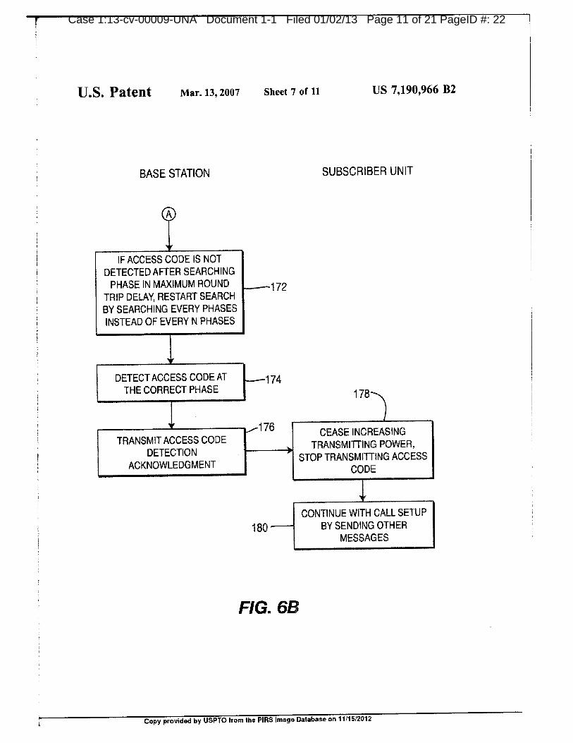
IF ACCESS CODE IS NOTDETECTED AFTER SEARCHING
PHASE IN MAXIMUM ROUND 172TRIP DELAY, RESTART SEARCHBY SEARCHING EVERY PHASESINSTEAD OF EVERY N PHASES
DETECT ACCESS CODE AT 174THE CORRECT PHASE 178
1,,--176TRANSMIT ACCESS CODE
CEASE INCREASING
DETECTIONTRANSMITTING POWER,
STOP TRANSMITTING ACCESSACKNOWLEDGMENT CODE
CONTINUE WITH CALL SETUP
180 BY SENDING OTHERMESSAGES
FIG. 6B
to' Copy provided by USPTO from the PIRS Image Database on 11/15/2012

Case 1:13-cv-0A0009-UNA Document 1-2 1-iled 01/02/13 Page 13 ot 24 PagelD 45 I
U.S. Patent Oct. 23, 2007 Sheet 8 of 11 US 7,286,847 B2
cc co 1Lu w CO CV0 LC)0 r
0,u) .4--,Er_ CC
I— CC—J ..^.mY,. 0 0
1–0 zco cc 5 cc 1
Tm w
LUIE) a_ co
c) z co w
r c.)
-T-OD
CCU) I—
LLI I— CD
c.)I— IICC CS) I
10U) Co CC 0LU
03 X iisft,
w ff_ Ca, ml-LII--I ILIL
am.
ILL if)ill11111111^W
CV
1 I—1.1.1 C.)
E o tu
CC0 CI 1111^11•••^
UJ Z IZEt
w TC.) LU ZUJ CC LU
CC) CC CL CDLC)i U) uj
.p.^. X 0
wCC CC 0 Cluj
C.)
'9r
cc
1–_, c•
ca LC)
t
r Copy provided by USPTO from the PIRS Image Database on 11/15/2012
46r Case 1:13-cv-00009-UNA Document 1-2 Filed 01/02/13 Page 14 of 24 Page
U.S. Patent Oct. 23, 2007 Sheet 9 of 11 US 7,286,847 B2
CD cc .44-o w r...--
-o)
z cn
Ci Cr0
^=.1..... CC 0 CD00 0 I-, CO
CC 2 CDCD Z CCLU,
r a Lu
CC u) .1.... CC C.9t 11 ujCV Z
0) CCCO c)
CC LLI 0I- 0
MU)Z 4 0cc Tawi—
0 ai— co----co Lu
i 0 NJ 0w cc
i xw 0.4- __I Zi CO a.
6 coi
c)CO
i I- LLI 1.L_t1, _i LLI
CCi A 0i CC I-,111 (.5i
cru.cc ui a Lu
i 0 1III LLII CD
r..-- cc cc 0 11 CL Ili 1I CO cii 1CC CVi 0 a)I Lii 0,i1 LTJ
0 1.t.CC
h-CI CV
N.-
Copy provided by USPTO from the PIRS Image Database on 11/15/2012
m-1

ment l-z Hieci Ul/UZ/E3 Hage lb or Z4 Hage
U.S. Patent Oct. 23, 2007 Sheet 10 of 11 US 7,286,847 B2
START
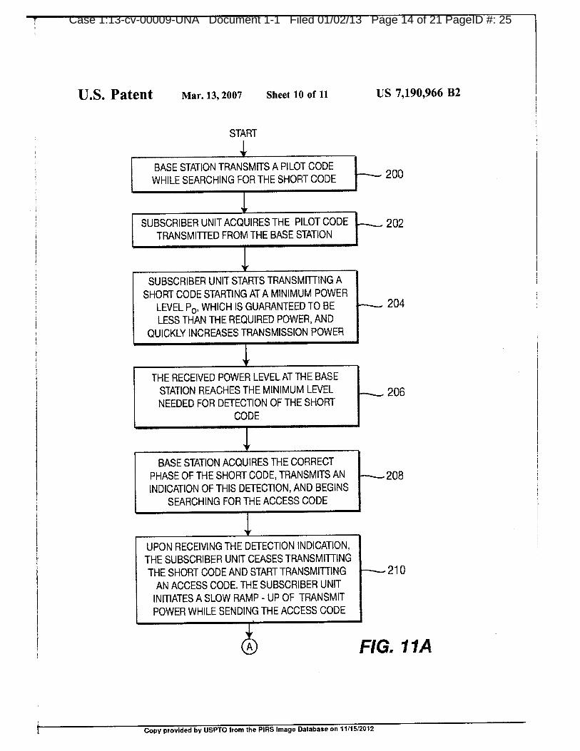
BASE STATION TRANSMITS A PILOT CODEWHILE SEARCHING FOR THE SHORT CODE 200
SUBSCRIBER UNIT ACQUIRES THE PILOT CODE I----- 202TRANSMITTED FROM THE BASE STATION
SUBSCRIBER UNIT STARTS TRANSMITTING A
SHORT CODE STARTING AT A MINIMUM POWERLEVEL Po, WHICH IS GUARANTEED TO BE 204LESS THAN THE REQUIRED POWER, AND
QUICKLY INCREASES TRANSMISSION POWER
THE RECEIVED POWER LEVEL AT THE BASESTATION REACHES THE MINIMUM LEVEL 206NEEDED FOR DETECTION OF THE SHORT
CODE
BASE STATION ACQUIRES THE CORRECTPHASE OF THE SHORT CODE, TRANSMITSAN,208INDICATION OF THIS DETECTION, AND BEGINS
SEARCHING FOR THE ACCESS CODE
UPON RECEIVING THE DETECTION INDICATION,THE SUBSCRIBER UNIT CEASES TRANSMITTINGTHE SHORT CODE AND START TRANSMITTING 210
AN ACCESS CODE. THE SUBSCRIBER UNITINITIATES A SLOW RAMP UP OF TRANSMITPOWER WHILE SENDING THE ACCESS CODE
FIG. 11A
Copy provided by USPTO from the P1RS Image Database on 11/15/2012
age
U.S. Patent Oct. 23, 2007 Sheet 11 of 11 US 7,286,847 B2
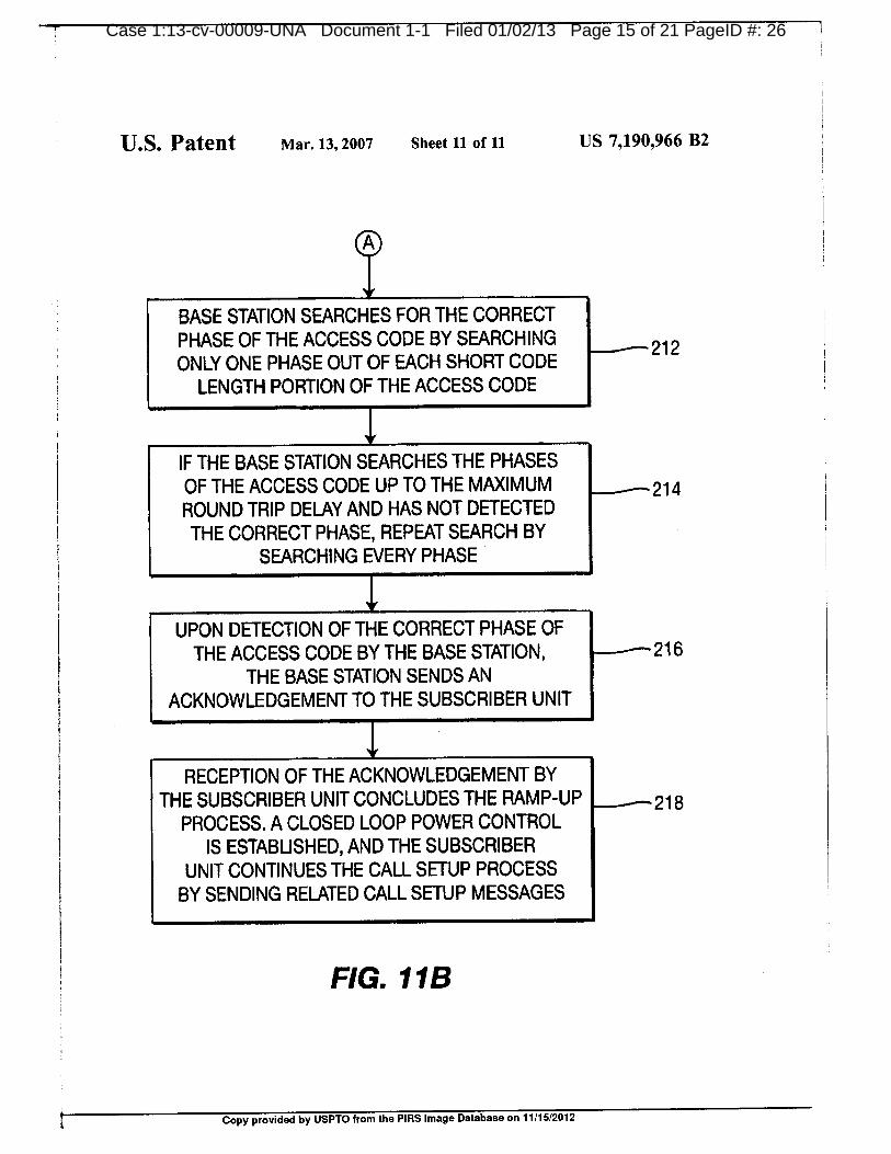
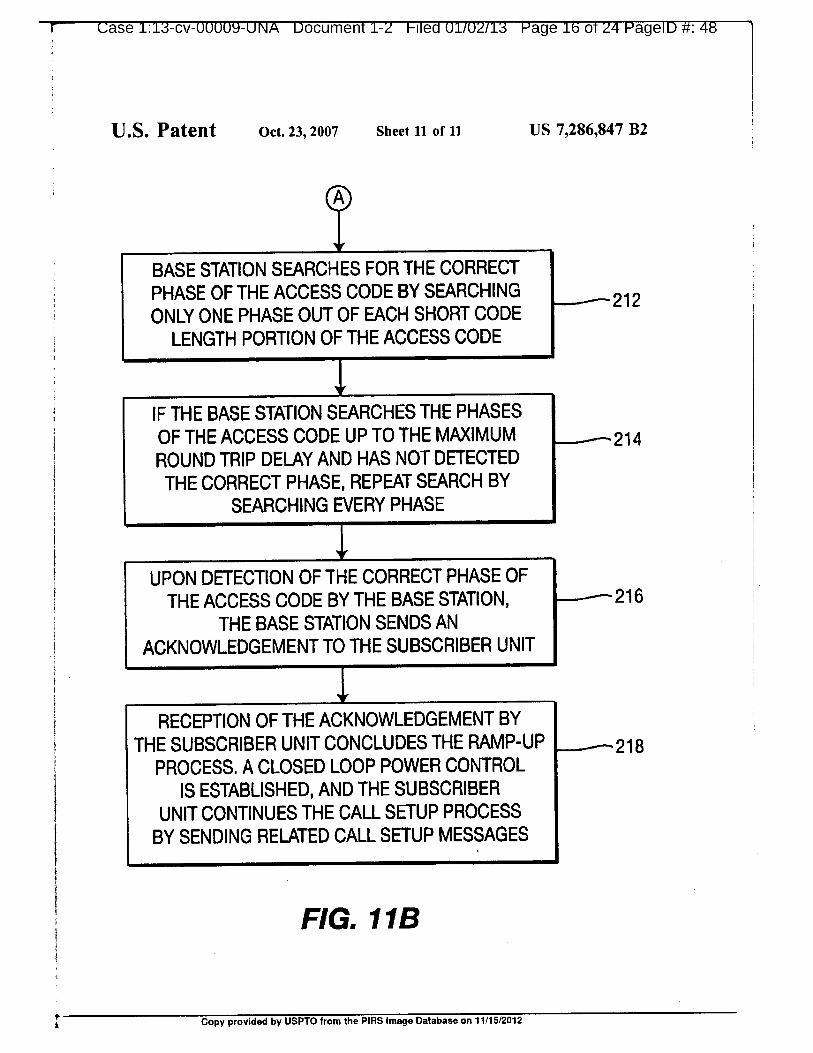
BASE STATION SEARCHES FOR THE CORRECTPHASE OF THE ACCESS CODE BY SEARCHING 212ONLY ONE PHASE OUT OF EACH SHORT CODE
LENGTH PORTION OF THE ACCESS CODE
IF THE BASE STATION SEARCHES THE PHASESOF THE ACCESS CODE UP TO THE MAXIMUM 214ROUND TRIP DELAY AND HAS NOT DETECTEDTHE CORRECT PHASE, REPEAT SEARCH BY
SEARCHING EVERY PHASE
UPON DETECTION OF THE CORRECT PHASE OFTHE ACCESS CODE BY THE BASE STATION, 216
THE BASE STATION SENDS ANACKNOWLEDGEMENT TO THE SUBSCRIBER UNIT
RECEPTION OF THE ACKNOWLEDGEMENT BYTHE SUBSCRIBER UNIT CONCLUDES THE RAMP-UP
PROCESS. A CLOSED LOOP POWER CONTROLIS ESTABLISHED, AND THE SUBSCRIBER
UNIT CONTINUES THE CALL SETUP PROCESSBY SENDING RELATED CALL SETUP MESSAGES
FIG. 11B
Copy provided by USPTO from the PIRS Image Database on 11/15/2012
uase 1:1.3-cv-UUUU9-UNA Uocument 1-2 Hied 01102113 Page 11 ot 24 P D 49age
US 7,286,847 B21 2
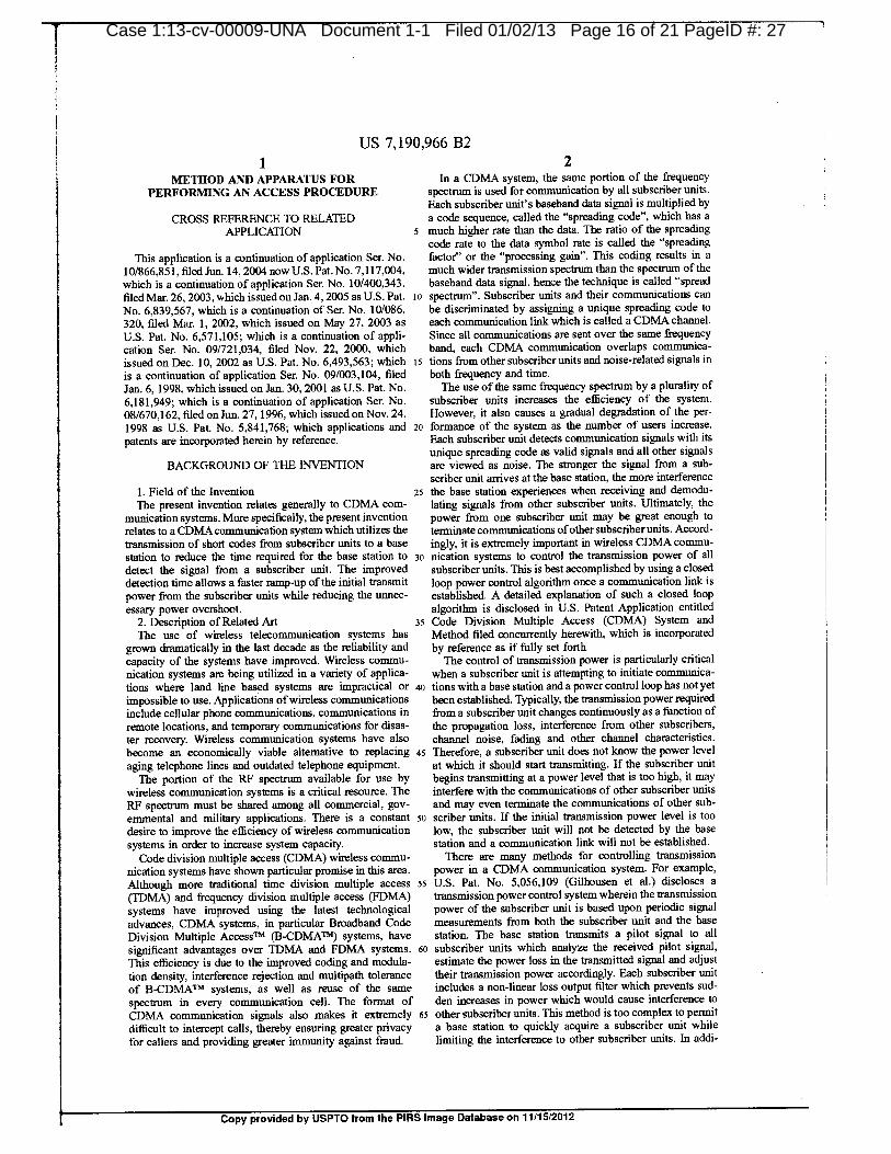
METHOD AND APPARATUS FOR In a CDMA system, the same portion of the frequencyPERFORMING AN ACCESS PROCEDURE spectrum is used for communication by all subscriber units.
1Each subscriber unit's baseband data signal is multiplied by
CROSS REFERENCE TO RELATED a code sequence, called the "spreading code", which has a
APPLICATION 5 much higher rate than the data. The ratio of the spreadingcode rate to the data symbol rate is called the "spreading
1 Ibis application is a continuation of application Ser. No. factor" or the "processing gain". This coding results in a
10/866,851, filed Jun. 14, 2004, now U.S. Pat. No. 7, 117,004 much wider transmission spectrum than the spectrum ofthe
which is a continuation of application Ser. No. 10/400,343, baseband data signal, hence the technique is called "spreadfiled Mar. 26, 2003, which issued on Jan. 4, 2005 as U.S. Pat. to spectrum". Subscriber units and their communications can
No. 6,839,567, which is a continuation of Ser. No. 10/086, be discriminated by assigning a unique spreading code to
320, filed Mar. 1, 2002, which issued on May 27, 2003 as each communication link which is called a CDMA channel.U.S. Pat. No. 6, 571, 105; which is a continuation of appli- Since all communications are sent over the same frequencycation Ser. No. 09/721,034, filed Nov. 22, 2000, which band, each CDMA communication overlaps communica-
1 issued on Dec. 10, 2002 as U.S. Pat. No. 6,493,563; which 15 tions from other subscriber units and noise-related signals in
is a continuation of application Ser. No. 09/003, 104, filed both frequency and time.Jan. 6, 1998, which issued on Jan. 30, 2001 as U.S. Pat. No. The use of the same frequency spectrum by a plurality of
6, 181,949; which is a continuation of application Ser. No. subscriber units increases the efficiency of the system.08/670, 162, filed on Jun. 27, 1996, which issued on Nov. 24, However, it also causes a gradual degradation of the per-1998 as U.S. Pat. No. 5,841,768; which applications and 20 formance of the system as the number of users increase.
patents are incorporated herein by reference. Each subscriber unit detects communication signals with its
unique spreading code as valid signals and all other signalsBACKGROUND OF THE INVENTION are viewed as noise. The stronger the signal from a sub-
scriber unit arrives at the base station, the more interference1. Field of the Invention 25 the base station experiences when receiving and demodu-lbe present invention relates generally to CDMA com- lating signals from other subscriber units. Ultimately, the
munication systems. More specifically, the present invention power from one subscriber unit may be great enough to
relates to a CDMA communication system which utilizes the terminate communications ofother subscriberunits. Accord-transmission of short codes from subscriber units to a base ingly, it is extremely important in wireless CDMA commu-
station to reduce the time required for the base station to 30 nication systems to control the transmission power of all
detect the signal from a subscriber unit. The improved subscriber units. This is best accomplished by using a closeddetection time allows a faster ramp-up of the initial transmit loop power control algorithm once a communication link is
power from the subscriber units while reducing the unnec- established. A detailed explanation of such a closed loopessary power overshoot, algorithm is disclosed in U.S. patent application entitled
2. Description of Related Art 35 Code Division Multiple Access (CDMA) System and
The use of wireless telecommunication systems has Method filed concurrently herewith, which is incorporatedgrown dramatically in the last decade as the reliability and by reference as if fully set forth.capacity of the systems have improved. Wireless commu- The control of transmission power is particularly criticalnication systems are being utilized in a variety of applica- when a subscriber unit is attempting to initiate communica-tions where land line based systems are impractical or 40 tions with a base station and a power control loop has not yetimpossible to use. Applications ofwireless communications been established. Typically, the transmission power requiredinclude cellular phone communications, communications in from a subscriber unit changes continuously as a function of
remote locations, and temporary communications for disas- the propagation loss, interference from other subscribers,ter recovery. Wireless communication systems have also channel noise, fading and other channel characteristics.become an economically viable alternative to replacing 45 Therefore, a subscriber unit does not know the power level
aging telephone lines and outdated telephone equipment. at which it should start transmitting. If the subscriber unitThe portion of the RF spectrum available for use by begins transmitting at a power level that is too high, it may
wireless communication systems is a critical resource. The interfere with the communications of other subscriber unitsRF spectrum must be shared among all commercial, gov- and may even terminate the communications of other sub-
ernmental and military applications. There is a constant so scriber units. If the initial transmission power level is too
desire to improve the efficiency of wireless communication low, the subscriber unit will not be detected by the base
systems in order to increase system capacity. station and a communication link will not be established.
Code division multiple access (CDMA) wireless commu- There are many methods for controlling transmission
nication systems have shown particular promise in this area. power in a CDMA communication system. For example,Although more traditional time division multiple access 55 U.S. Pat. No. 5,056,109 (Gilhousen et al.) discloses a
(TDMA) and frequency division multiple access (FDMA) transmission power control system wherein the transmission
systems have improved using the latest technological power of the subscriber unit is based upon periodic signaladvances, CDMA systems, in particular Broadband Code measurements from both the subscriber unit and the base
Division Multiple AccessTM (B-CDMATM) systems, have station. The base station transmits a pilot signal to all
significant advantages over TDMA and FDMA systems. 60 subscriber units which analyze the received pilot signal,This efficiency is due to the improved coding and modula- estimate the power loss in the transmitted signal and adjusttion density, interference rejection and multipath tolerance their transmission power accordingly. Each subscriber unit
of B-CDMATM systems, as well as reuse of the same includes a non-linear loss output filter which prevents sud-
spectrum in every communication cell. The format of den increases in power which would cause interference to
CDMA communication signals also makes it extremely 65 other subscriber units. This method is too complex to permitdifficult to intercept calls, thereby ensuring greater privacy a base station to quickly acquire a subscriber unit while
for callers and providing greater immunity against fraud, limiting the interference to other subscriber units. In addi-
3
Copy provided by USPTO from the P1RS Image Database on 11/15/2012
Copy provided
PagelD 50
US 7,286,847 B2
3 4
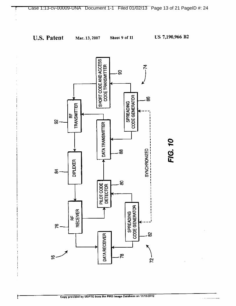
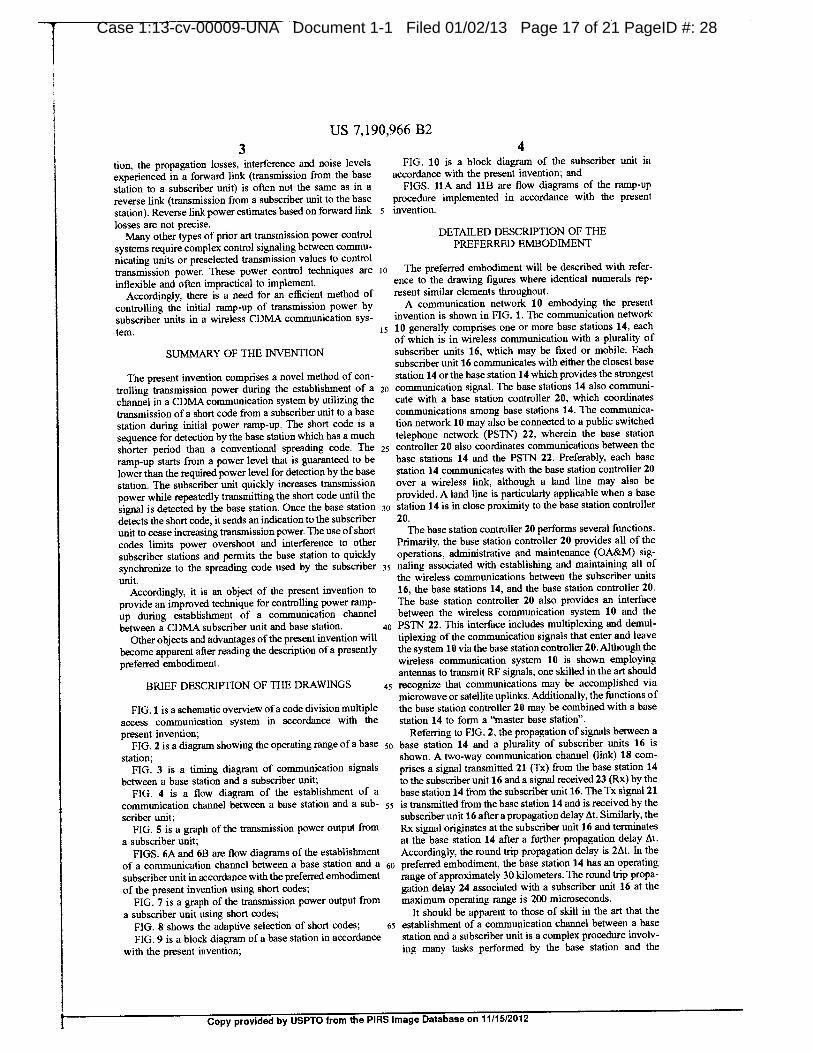
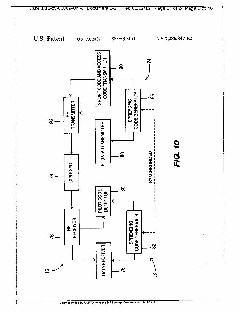
tion the propagation losses, interference and noise levels FIG. 10 is a block diagram of the subscriber unit in
experienced in a forward link (transmission from the base accordance with the present invention; and
station to a subscriber unit) is often not the same as in a FIGS. nA and 11B are flow diagrams of the ramp-upreverse link (transmission from a subscriber unit to the base procedure implemented in accordance with the presentstation). Reverse link power estimates based on forward link 5 invention.losses are not precise.
Many other types of prior art transmission power control DETAILED DESCRIPTION OF THE
systems require complex control signaling between commu- PREFERRED EMBODIMENT
nicating units or preselected transmission values to controltransmission power. These power control techniques are to The preferred embodiment will be described with refer-
inflexible and often impractical to implement. ence to the drawing figures where identical numerals rep-
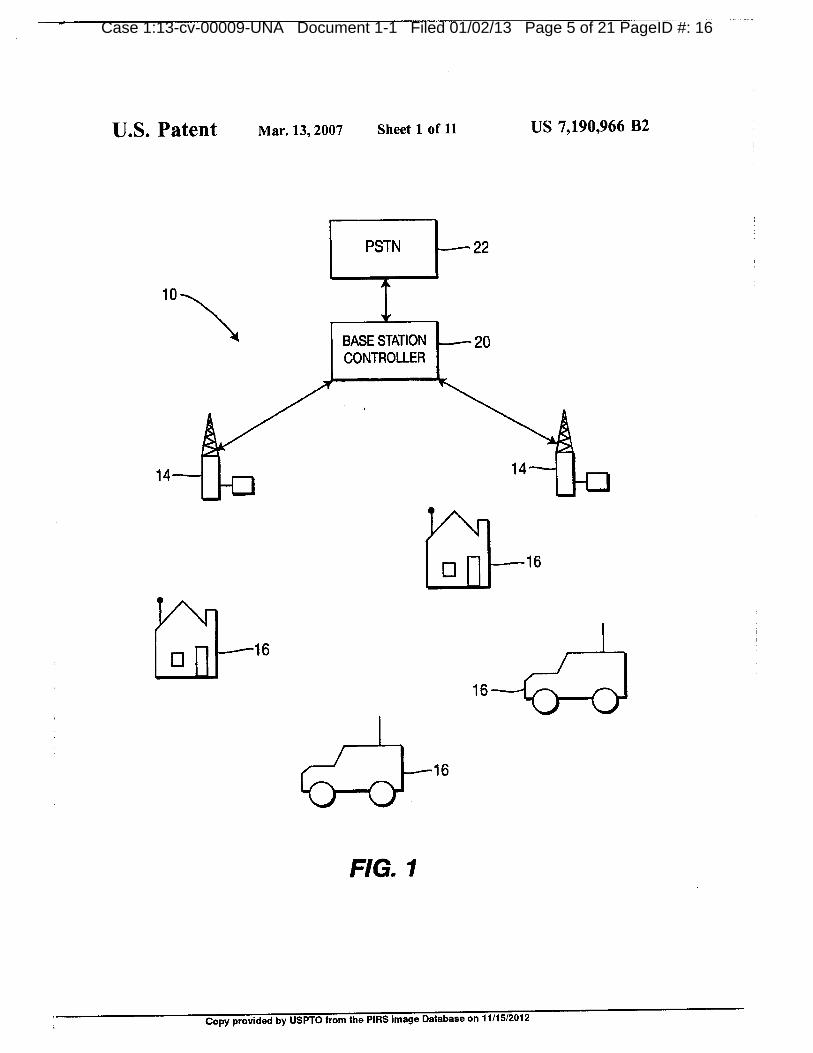
Accordingly, there is a need for an efficient method of resent similar elements throughout.controlling the initial ramp-up of transmission power by A communication network 10 embodying the presentsubscriber units in a wireless CDMA communication sys- invention is shown in FIG. 1. The communication network
tem. is 10 generally comprises one or more base stations 14, eachof which is in wireless communication with a plurality of
SUMMARY OF THE INVENTION subscriber units 16, which may be fixed or mobile. Eachsubscriber unit 16 communicates with either the closest base
The present invention comprises a novel method of con- station 14 or the base station 14 which provides the strongesttrolling transmission power during the establishment of a 20 communication signal. The base stations 14 also communi-channel in a CDMA communication system by utilizing the cate with a base station controller 20, which coordinates
transmission of a short code from a subscriber unit to a base communications among base stations 14. The communica-station during initial power ramp-up. The short code is a tion network 10 may also be connected to a public switched
sequence for detection by the base station which has a much telephone network (PSTN) 22, wherein the base station
shorter period than a conventional spreading code. The 25 controller 20 also coordinates communications between the
ramp-up starts from a power level that is guaranteed to be base stations 14 and the PSTN 22. Preferably, each base
lower than the required power level for detection by the base station 14 communicates with the base station controller 20
station. The subscriber unit quickly increases transmission over a wireless link, although a land line may also be
power while repeatedly transmitting the short code until the provided. A land line is particularly applicable when a base
signal is detected by the base station. Once the base station 30 station 14 is in close proximity to the base station controller
detects the short code, it sends an indication to the subscriber 20.unit to cease increasing transmission power. The use ofshort The base station controller 20 performs several functions.
codes limits power overshoot and interference to other Primarily, the base station controller 20 provides all of the
subscriber stations and permits the base station to quickly operations, administrative and maintenance (0A&M) sig-synchronize to the spreading code used by the subscriber 35 naling associated with establishing and maintaining all of
unit, the wireless communications between the subscriber units
Accordingly, it is an object of the present invention to 16, the base stations 14, and the base station controller 20.
provide an improved technique for controlling power ramp- The base station controller 20 also provides an interface
up during establishment of a communication channel between the wireless communication system 10 and the
between a CDMA subscriber unit and base station. o PSTN 22. This interface includes multiplexing and demul-
Other objects and advantages ofthe present invention will tiplexing of the communication signals that enter and leavebecome apparent after reading the description of a presently the system 10 via the base station controller20. Although the
preferred embodiment. wireless communication system 10 is shown employingantennas to transmit RF signals, one skilled in the art should
BRIEF DESCRIPTION OF THE DRAWINGS 45 recognize that communications may be accomplished viamicrowave or satellite uplinks. Additionally, the functions of
FIG. 1 is a schematic overview ofa code division multiple the base station controller 20 may be combined with a base
access communication system in accordance with the station 14 to form a "master base station".
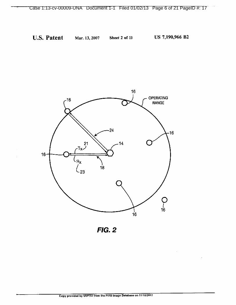
present invention; Referring to FIG. 2, the propagation of signals between a
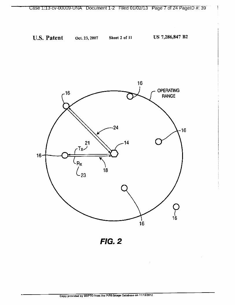
FIG. 2 is a diagram showing the operating range of a base 5o base station 14 and a plurality of subscriber units 16 is
station; shown. A two-way communication channel (link) 18 com-
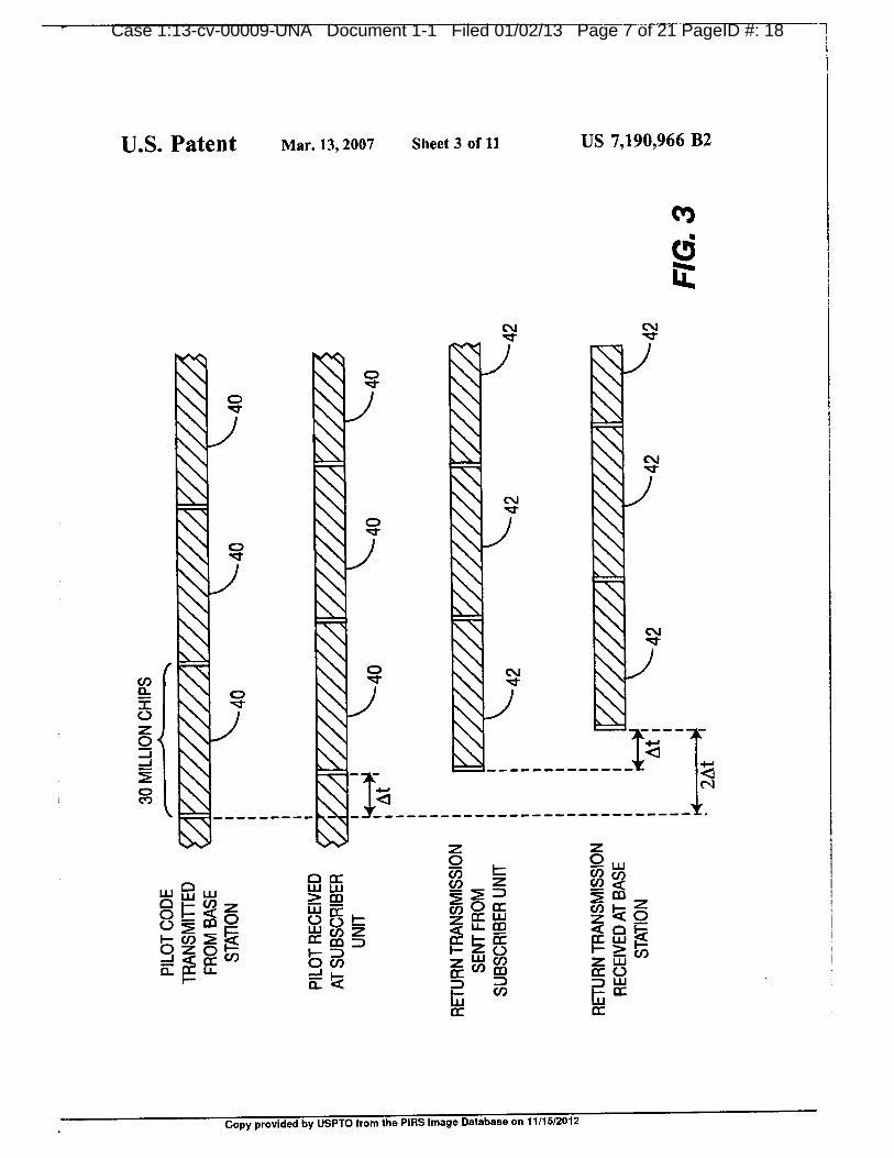
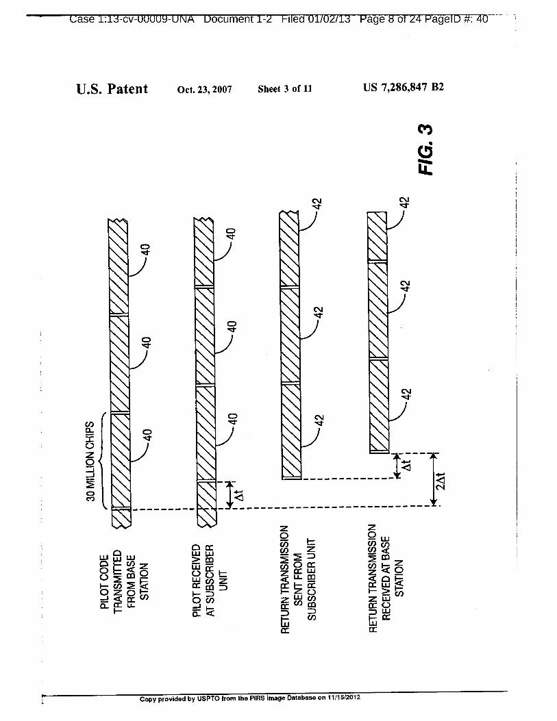
FIG. 3 is a timing diagram of communication signals prises a signal transmitted 21 (Tx) from the base station 14between a base station and a subscriber unit; to the subscriber unit 16 and a signal received 23 (Rx) by the
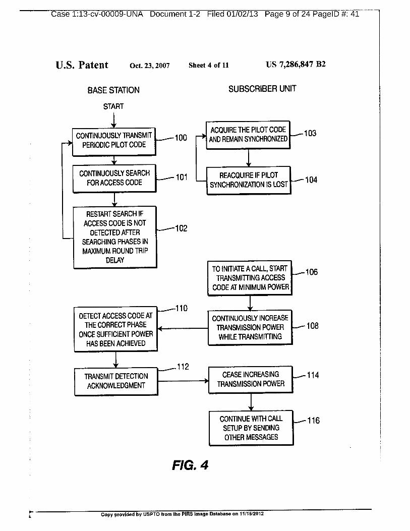
FIG. 4 is a flow diagram of the establishment of a base station 14 from the subscriber unit 16. The Tx signal 21communication channel between a base station and a sub- 55 is transmitted from the base station 14 and is received by thescriber unit; subscriber unit 16 after a propagation delay M. Similarly, the
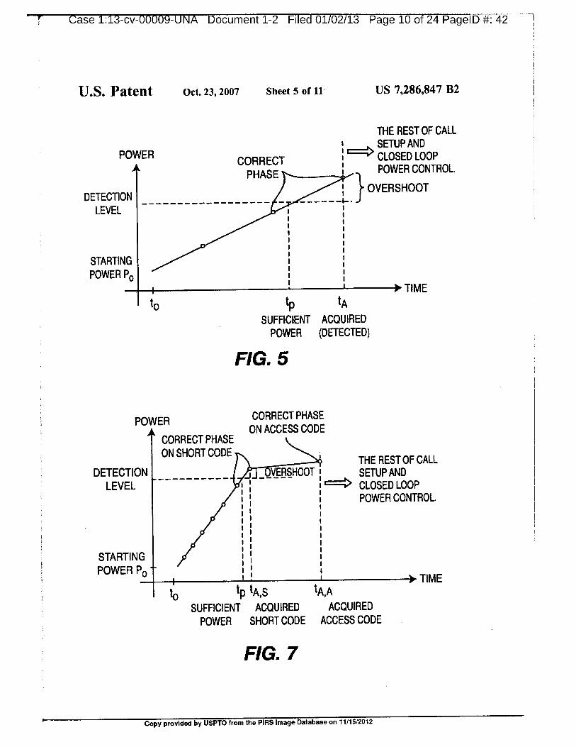
FIG. 5 is a graph of the transmission power output from Rx signal originates at the subscriber unit 16 and terminatesa subscriber unit; at the base station 14 after a further propagation delay At.
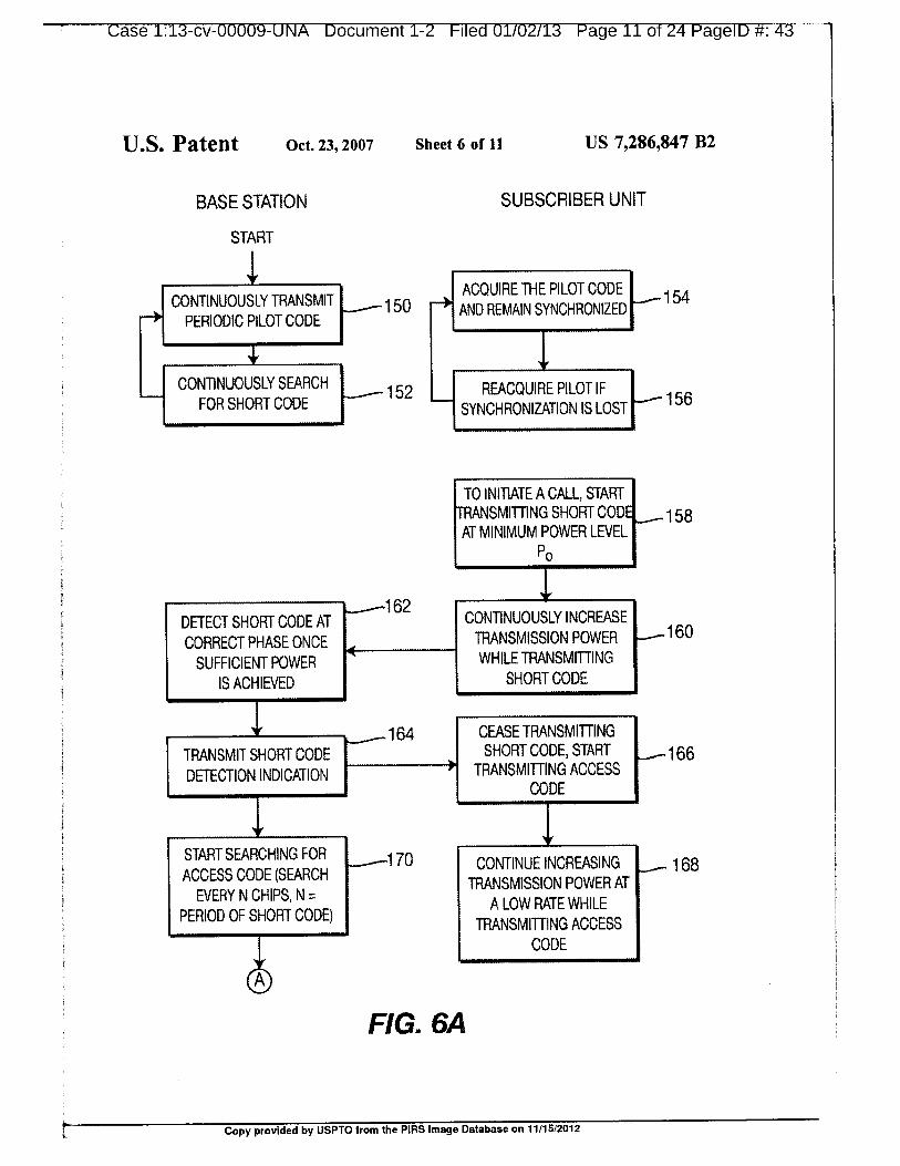
FIGS. 6A and 6B are flow diagrams of the establishment Accordingly, the round trip propagation delay is 2M. In theof a communication channel between a base station and a 60 preferred embodiment, the base station 14 has an operatingsubscriber unit in accordance with the preferred embodiment range of approximately 30 kilometers. The round trip propa-of the present invention using short codes; gation delay 24 associated with a subscriber unit 16 at the
FIG. 7 is a graph of the transmission power output from maximum operating range is 200 microseconds.a subscriber unit using short codes; It should be apparent to those of skill in the art that the
FIG. 8 shows the adaptive selection of short codes; 65 establishment of a communication channel between a base
FIG. 9 is a block diagram of a base station in accordance station and a subscriber unit is a complex procedure involv-with the present invention; ing many tasks performed by the base station and the
by USPTO from the PIRS Image Database on 11/15/2012
r Case 1:13-cv-00009-UNA Document 1-2 1-iled 01/02/13 Page 18 6T-24

ease 1:1.3-Cv-UUUU9-UNA uocument 1-z Hied ulluz/Ls Hage la of zzi-vageiu #:51
US 7,286,847 B25 6
subscriber unit which are outside the scope of the present In a first embodiment of the present invention the sub-invention. The present invention is directed to initial power scriber unit 16 starts transmitting at a power level guaran-
ramp-up and synchronization during the establishment of a teed to be lower than what is required and increases trans-
communication channel. mission power output until the correct power level is
Referring to FIG. 3, the signaling between a base station 5 achieved. This avoids sudden introduction of a strong inter-14 and a subscriber unit 16 is shown. In accordance with the ference, hence improving system 10 capacity.present invention, the base station 14 continuously transmits The establishment of a communication channel in accor-
a pilot code 40 to all ofthe subscriber units 16 located within dance with the present invention and the tasks performed bythe transmitting range of the base station 14. The pilot code the base station 14 and a subscriber unit 16 are shown in40 is a spreading code which carries no data bits. The pilot to FIG. 4. Although many subscriber units 16 may be locatedcode 40 is used for subscriber unit 16 acquisition and within the operating range of the base station 14, reference
synchronization, as well as for determining the parameters will be made hereinafter to a single subscriber unit 16 for
of the adaptive matched filter used in the receiver, simplicity in explaining the operation of the present inven-The subscriber unit 16 must acquire the pilot code 40 tion.
transmitted by the base station 14 before it can receive or 15 The base station 14 begins by continuously transmitting a
transmit any data. Acquisition is the process whereby the periodic pilot code 40 to all subscriber units 16 located
subscriber unit 16 aligns its locally generated spreading code within the operating range of the base station 14 (step 100).with the received pilot code 40. The subscriber unit 16 As the base station 14 transmits the pilot code 40 (step 100),searches through all of the possible phases of the received the base station 14 searches (step 101) for an "access code"
pilot code 40 until it detects the correct phase, (the beginning 20 42 transmitted by a subscriber unit 16. The access code 42of the pilot code 40). is a known spreading code transmitted from a subscriber unit
The subscriber unit 16 then synchronizes its transmit 16 to the base station 14 during initiation ofcommunications
spreading code to the received pilot code 40 by aligning the and power ramp-up. The base station 14 must search throughbeginning of its transmit spreading code to the beginning of all possible phases (time shifts) of the access code 42
the pilot code 40. One implication of this receive and 25 transmitted from the subscriber unit 16 in order to find thetransmit synchronization is that the subscriber unit 16 intro- correct phase. This is called the "acquisition" or the "detec-duces no additional delay as far as the phase ofthe spreading tion" process (step 101). The longer the access code 42, thecodes are concerned. Accordingly, as shown in FIG. 3, the longer it takes for the base station 14 to search through therelative delay between the pilot code 40 transmitted from the phases and acquire the correct phase.base station 14 and the subscriber unit's transmit spreading 30 As previously explained, the relative delay between sig-code 42 received at the base station 14 is 2At, which is solely nals transmitted from the base station 14 and return signalsdue to the round trip propagation delay. received at the base station 14 corresponds to the round trip
In the preferred embodiment, the pilot code is 29,877, 120 propagation delay 2At. The maximum delay occurs at the
chips in length and takes approximately 2 to 5 seconds to maximum operating range of the base station 14, known as
transmit, depending on the spreading factor. The length of 35 the cell boundary. Accordingly, the base station 14 must
the pilot code 40 was chosen to be a multiple of the data search up to as many code phases as there are in the
symbol no matter what kind of data rate or bandwidth is maximum round trip propagation delay, which is typicallyused. As is well known by those of skill in the art, a longer less code phases than there are in a code period.pilot code 40 has better randomness properties and the For a data rate Rb and spreading code rate Rc, the ratio
frequency response of the pilot code 40 is more uniform. 40 L=Rc/Rb is called the spreading factor or the processingAdditionally, a longer pilot code 40 provides low channel gain. In the preferred embodiment of the present invention,cross correlation, thus increasing the capacity of the system the cell boundaty radius is 30 km, which corresponds to
10 to support more subscriber units 16 with less interference, approximately between 1000 and 2500 code phases in theThe use of a long pilot code 40 also supports a greater maximum round trip delay, depending on the processingnumber of random short codes. For synchronization pur- 45 gain.poses, the pilot code 40 is chosen to have the same period Ifthe base station 14 has not detected the access code afteras all of the other spreading codes used by the system 10. searching through the code phases corresponding to the
Thus, once a subscriber unit 16 acquires the pilot code 40, maximum round trip delay the search is repeated startingit is synchronized to all other signals transmitted from the from the phase of the pilot code 40 which corresponds to
base station 14. so zero delay (step 102).During idle periods, when a call is not in progress or During idle periods, the pilot code 40 from the base
pending, the subscriber unit 16 remains synchronized to the station 14 is received at the subscriber unit 16 whichbase station 14 by periodically reacquiring the pilot code 40. periodically synchronizes its transmit spreading code gen-This is necessary for the subscriber unit 16 to receive and erator thereto (step 103). If synchronization with the pilotdemodulate any downlink transmissions, in particular pag- ss code 40 is lost, the subscriber unit 16 reacquires the piloting messages which indicate incoming calls. code 40 and resynchronizes (step 104).
When a communication link is desired, the base station 14 When it is desired to initiate a communication link, the
must acquire the signal transmitted from the subscriber unit subscriber unit 16 starts transmitting the access code 42 back16 before it can demodulate the data. The subscriber unit 16 to the base station 14 (step 106). The subscriber unit 16
must transmit an uplink signal for acquisition by the base 60 continuously increases the transmission power whilestation 14 to begin establishing the two-way communication retransmitting the access code 42 (step 108) until it receives
link. A critical parameter in this procedure is the transmis- an acknowledgment from the base station 14. The basesion power level of the subscriber unit 16. A transmission station 14 detects the access code 42 at the correct phasepower level that is too high can impair communications in once the minimum power level for reception has beenthe whole service area, whereas a transmission power level 65 achieved (step 110). The base station 14 subsequently trans-
that is too low can prevent the base station 14 from detecting mits an access code detection acknowledgment signal (stepthe uplink signal. 112) to the subscriber unit 16. Upon receiving the acknowl-
Copy provided by USPTO from the PIRS Image Database on 11/15/2012

7 8US 7,286,847 B2
edgment, the subscriber unit ceases the transmission power sion power level while retransmitting the short code (stepincrease (step 114). With the power ramp-up completed, 160) until it receives an acknowledgment from the base
closed loop power control and call setup signaling is per- station 14 that the short code has been detected by the base
formed (step 116) to establish the two-way communication station 14.
link. 5 The access code in the preferred embodiment, as previ-Although this embodiment limits subscriber unit 16 trans- ously described herein, is approximately 30 million chips in
mission power, acquisition of the subscriber unit 16 by the length. However, the short code is much smaller. The short
base station 14 in this manner may lead to unnecessary code can be chosen to be any length that is sufficiently short
power overshoot from the subscriber unit 16, thereby reduc- to permit quick detection. There is an advantage in choosing
ing the performance of the system 10. 10 a short code length such that it divides the access code
The transmission power output profile of the subscriber period evenly. For the access code described herein, the
unit 16 is shown in FIG. 5. At to, the subscriber unit 16 starts short code is preferably chosen to be 32, 64 or 128 chips in
transmitting at the starting transmission power level Po, length. Alternatively, the short code may be as short as one
which is a power level guaranteed to be less than the power symbol length, as will be described in detail hereinafter.
level required for detection by the base station 14. The 15 Since the start of the short code and the start of the access
subscriber unit 16 continually increases the transmission code are synchronized, once the base station 14 acquires the
power level until it receives the detection indication from the short code, the base station 14 knows that the correspondingbase station 14. For the base station 14 to properly detect the phase of the access code is an integer multiple of N chipsaccess code 42 from the subscriber unit 16 the access code fromthe phase of the short code where N is the length ofthe
42 must: 1) be received at a sufficient power level; and 2) be 20 short code. Accordingly, the base station 14 does not have to
detected at the proper phase. Accordingly, referring to FIG. search all possible phases corresponding to the maximum
5, although the access code 42 is at a sufficient power level round trip propagation delay.for detection by the base station 14 at tp, the base station 14 Using the short code, the correct phase for detection bymust continue searching for the correct phase of the access the base station 14 occurs much more frequently. When the
code 42 which occurs at t„, 25 minimum power level for reception has been achieved, the
Since the subscriber unit 16 continues to increase the short code is quickly detected (step 162) and the transmis-
output transmission power level until it receives the detec- sion power overshoot is limited. The transmission power
tion indication from the base station 14, the transmission ramp-up rate may be significantly increased without concern
power of the access code 42 exceeds the power level for a large power overshoot. In the preferred embodiment of
required for detection by the base station 14. This causes 30 the present invention, the power ramp-up rate using the short
unnecessary interference to all other subscriber units 16. If code is 1 dB per millisecond.
the power overshoot is too large, the interference to other The base station 14 subsequently transmits a short code
subscriber units 16 may be so severe as to terminate ongoing detection indication signal (step 164) to the subscriber unit
communications of other subscriber units 16. 16 which enters the second stage ofthe power ramp-up upon
The rate that the subscriber unit 16 increases transmission 35 receiving this indication. In this stage, the subscriber unit 16
power to avoid overshoot may be reduced, however, this ceases transmitting the short code (step 166) and starts
results in a longer call setup time. Those of skill in the art continuously transmitting a periodic access code (step 166).would appreciate that adaptive ramp-up rates can also be The subscriber unit 16 continues to ramp-up its transmission
used, yet these rates have shortcomings and will not appre- power while transmitting the access code, however the
ciably eliminate power overshoot in all situations. ao ramp-up rate is now much lower than the previous ramp-up
The preferred embodiment of the present invention uti- rate used with the short code (step 168). The ramp-up rate
lizes "short codes" and a two-stage communication link with the access code is preferably 0.05 dB per millisecond.
establishment procedure to achieve fast power ramp-up The slow ramp-up avoids losing synchronization with the
without large power overshoots. The spreading code trans- base station 14 due to small changes in channel propagationmitted by the subscriber unit 16 is much shorter than the rest 45 characteristics.of the spreading codes (hence the term short code), so that At this point, the base station 14 has detected the short
the number of phases is limited and the base station 14 can code at the proper phase and power level (step 162). The
quickly search through the code. The short code used for this base station 14 must now synchronize to the access code
purpose carries no data. which is the same length as all other spreading codes and
The tasks performed by the base station 14 and the so much longer than the short code. Utilizing the short code, the
subscriber unit 16 to establish a communication channel base station 14 is able to detect the proper phase of the
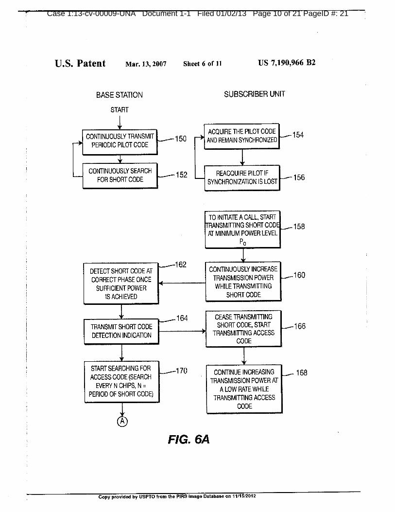
using short codes in accordance with the preferred embodi- access code much more quickly. The base station 14 beginsment of the present invention are shown in FIGS. 6A and 6B. searching for the proper phase of the access code (step 170).During idle periods, the base station 14 periodically and However, since the start of the access code is synchronizedcontinuously transmits the pilot code to all subscriber units 55 with the start of the short code, the base station 14 is only16 located within the operating range of the base station 14 required to search every N chips; where N=the length ofthe
(step 150). The base station 14 also continuously searches short code. ln summary, the base station 14 quickly acquiresfor a short code transmitted by the subscriber unit 16 (step the access code of the proper phase and power level by: 1)152). The subscriber unit 16 acquires the pilot code and detecting the short code; and 2) determining the proper
synchronizes its transmit spreading code generator to the 60 phase of the access code by searching every N chips of the
pilot code (step 154). The subscriber unit 16 also periodi- access code from the beginning of the short code.
cally checks to ensure it is synchronized. If synchronization If the proper phase of the access code has not been
is lost, the subscriber unit 16 reacquires the pilot signal detected after searching the number of phases in the maxi-
transmitted by the base station (step 156). mum round trip delay the base station 14 restarts the search
When a communication link is desired, the subscriber unit 65 for the access code by searching every chip instead of every
16 starts transmitting a short code at the minimum power N chips (step 172). When the proper phase of the access
level Po (step 158) and continuously increases the transmis- code has been detected (step 174) the base station 14
Copy provided by USPTO from the PIRS Image Database on 11/15/2012
ease 1:1.3-Cv-UUUU9-UNA uocument i-z Hled 1/1/UZ/1.3 Hage zu of Z4 Hagen) 4: 52

ease 1:1.3-Cv-UUUU9-UNA uocument 1-2 1-ilea 0110211.3 Page 21 ot 24 P D 53age
US 7,286,847 B2
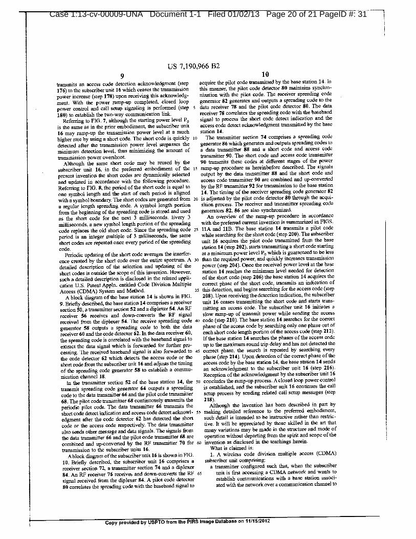
9 10transmits an access code detection acknowledgment (step acquire the pilot code transmitted by the base station 14. ln
176) to the subscriber unit 16 which ceases the transmission this manner, the pilot code detector 80 maintains synchro-power increase (step 178) upon receiving this acknowledg- nization with the pilot code. The receiver spreading code
ment. With the power ramp-up completed, closed loop generator 82 generates and outputs a spreading code to the
power control and call setup signaling is performed (step 5 data receiver 78 and the pilot code detector 80. The data
180) to establish the two-way communication link. receiver 78 correlates the spreading code with the baseband
Referring to FIG. 7, although the starting power level P. signal to process the short code detect indication and the
is the same as in the prior embodiment, the subscriber unit access code detect acknowledgment transmitted by the base
16 may ramp-up the transmission power level at a much station 14.
higher rate by using a short code. The short code is quickly ro The transmitter section 74 comprises a spreading code
detected after the transmission power level surpasses the generator 86 which generates and outputs spreading codes to
minimum detection level, thus minimizing the amount of a data transmitter 88 and a short code and access code
transmission power overshoot. transmitter 90. The short code and access code transmitter
Although the same short code may be reused by the 90 transmits these codes at different stages of the power
subscriber unit 16, in the preferred embodiment of the 15 ramp-up procedure as hereinbefore described. The signalspresent invention the short codes are dynamically selected output by the data transmitter 88 and the short code and
and updated in accordance with the following procedure. access code transmitter 90 are combined and up-convertedReferring to FIG. 8, the period of the short code is equal to by the RF transmitter 92 for transmission to the base station
one symbol length and the start of each period is aligned 14. The timing of the receiver spreading code generator 82
with a symbol boundary. The short codes are generated from 20 is adjusted by the pilot code detector 80 through the acqui-a regular length spreading code. A symbol length portion sition process. The receiver and transmitter spreading code
from the beginning of the spreading code is stored and used generators 82, 86 are also synchronized.as the short code for the next 3 milliseconds. Every 3 An overview of the ramp-up procedure in accordance
milliseconds, a new symbol length portion of the spreading with the preferred current invention is summarized in FIGS.
code replaces the old short code. Since the spreading code 25 11A and 11B. The base station 14 transmits a pilot code
period is an integer multiple of 3 milliseconds, the same while searching for the short code (step 200). The subscriber
short codes are repeated once every period of the spreading unit 16 acquires the pilot code transmitted from the base
code. station 14 (step 202), starts transmitting a short code startingPeriodic updating of the short code averages the interfer- at a minimum power level P. which is guaranteed to be less
ence created by the short code over the entire spectrum. A 30 than the required power, and quickly increases transmission
detailed description of the selection and updating of the power (step 204). Once the received power level at the base
short codes is outside the scope of this invention. However, station 14 reaches the minimum level needed for detection
such a detailed description is disclosed in the related appli- of the short code (step 206) the base station 14 acquires the
cation U.S. patent appin. entitled Code Division Multiple correct phase of the short code, transmits an indication of
Access (CDMA) System and Method. 35 this detection, and begins searching for the access code (stepA block diagram of the base station 14 is shown in FIG. 208). Upon receiving the detection indication, the subscriber
9. Briefly described, the base station 14 comprises a receiver unit 16 ceases transmitting the short code and starts trans-
section 50, a transmitter section 52 and a diplexer 54. An RF milting an access code. The subscriber unit 16 initiates a
receiver 56 receives and down-converts the RF signal slow ramp-up of transmit power while sending the access
received from the diplexer 54. The receive spreading code 40 code (step 210). The base station 14 searches for the correct
generator 58 outputs a spreading code to both the data phase ofthe access code by searching only one phase out of
receiver 60 and the code detector 62. In the data receiver 60, each short code length portion of the access code (step 212).the spreading code is correlated with the baseband signal to If the base station 14 searches the phases of the access code
extract the data signal which is forwarded for further pro- up to the maximum round trip delay and has not detected the
cessing. The received baseband signal is also forwarded to 45 correct phase, the search is repeated by searching everythe code detector 62 which detects the access code or the phase (step 214). Upon detection of the correct phase ofthe
short code from the subscriber unit 16 and adjusts the timing access code by the base station 14, the base station 14 sends
of the spreading code generator 58 to establish a commu- an acknowledgment to the subscriber unit 16 (step 216).nication channel 18. Reception ofthe acknowledgment by the subscriber unit 16
In the transmitter section 52 of the base station 14, the so concludes the ramp-up process. A closed loop power control
transmit spreading code generator 64 outputs a spreading is established, and the subscriber unit 16 continues the call
code to the data transmitter 66 and the pilot code transmitter setup process by sending related call setup messages (step68. The pilot code transmitter 68 continuously transmits the 218).periodic pilot code. The data transmitter 66 transmits the Although the invention has been described in part byshort code detect indication and access code detect acknowl- 55 making detailed reference to the preferred embodiment,edgment after the code detector 62 has detected the short such detail is intended to be instructive rather than restric-
code or die access code respectively. The data transmitter tive. It will be appreciated by those skilled in the art that
also sends other message and data signals. The signals from many variations may be made in the structure and mode of
the data transmitter 66 and the pilot code transmitter 68 are operation without departing from the spirit and scope ofthe
combined and up-converted by the RF transmitter 70 for 60 invention as disclosed in the teachings herein.
transmission to the subscriber units 16.Ablock diagram of the subscriber unit 16 is shown in FIG. What is claimed is:
10. Briefly described, the subscriber unit 16 comprises a 1. A wireless code division multiple access (CDMA)receiver section 72, a transmitter section 74 and a diplexer subscriber unit comprising:84. An RF receiver 76 receives and down-converts the RF 65 a circuit configured to synchronize to a pilot signalsignal received from the diplexer 84. A pilot code detector transmitted by a base station associated with a CDMA
80 correlates the spreading code with the baseband signal to network wherein, during idle periods of the subscriber
Copy provided by USPTO from the PIRS Image Database on 11/15/2012
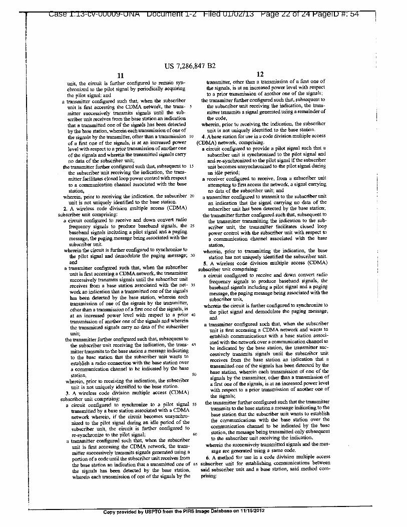
ease 1.1j-Clf-ULAJUV-UNH uocument i-z Ul/UZ/1,3 Hage zz of z4 Hageiu 54
US 7,286,847 B2
11 12
unit, the circuit is further configured to remain syn- transmitter, other than a transmission of a first one of
chronized to the pilot signal by periodically acquiring the signals, is at an increased power level with respectthe pilot signal; and to a prior transmission of another one of the signals;
a transmitter configured such that, when the subscriber the transmitter further configured such that, subsequent to
unit is first accessing the CDMA network, the trans- 5 the subscriber unit receiving the indication, the trans-
mitter successively transmits signals until the sub- mitter transmits a signal generated using a remainder of
scriber unit receives from the base station an indication the code,that a transmitted one of the signals has been detected wherein, prior to receiving the indication, the subscriber
by the base station, wherein each transmission ofone of unit is not uniquely identified to the base station.
the signals by the transmitter, other than a transmission to 4. A base station for use in a code division multiple access
of a first one of the signals, is at an increased power (CDMA) network, comprising:level with respect to a prior transmission ofanother one a circuit configured to provide a pilot signal such that a
of the signals and wherein the transmitted signals cany subscriber unit is synchronized to the pilot signal and
no data of the subscriber unit; and re-synchronized to the pilot signal if the subscriberthe transmitter further configured such that, subsequent to 15 unit becomes unsynchronized to the pilot signal during
the subscriber unit receiving the indication, the trans- an idle period;mitter facilitates closed loop power control with respect a receiver configured to receive, from a subscriber unitto a communication channel associated with the base attempting to first access the network, a signal carryingstation, no data of the subscriber unit; and
wherein, prior to receiving the indication, the subscriber 20 a transmitter configured to transmit to the subscriber unitunit is not uniquely identified to the base station, an indication that the signal carrying no data of the
2. A wireless code division multiple access (CDMA) subscriber unit has been detected by the base station;subscriber unit comprising: the transmitter further configured such that, subsequent to
a circuit configured to receive and down convert radio the transmitter transmitting the indication to the sub-frequency signals to produce baseband signals, the 25 scriber unit, the transmitter facilitates closed loopbaseband signals including a pilot signal and a paging power control with the subscriber unit with respect to
message, the paging message being associated with thea communication channel associated with the base
subscriber unit, station,wherein the circuit is further configured to synchronize to wherein, prior to transmitting the indication, the base
the pilot signal and demodulate the paging message; 30 station has not uniquely identified the subscriber unit.and 5. A wireless code division multiple access (CDMA)
a transmitter configured such that, when the subscriber subscriber unit comprising:unit is first accessing a CDMA network, the transmitter
a circuit configured to receive and down convert radiosuccessively transmits signals until the subscriber unit
frequency signals to produce baseband signals, thereceives from a base station associated with the net- 35 baseband signals including a pilot signal and a pagingwork an indication that a transmitted one of the signals message, the paging message being associated with thehas been detected by the base station, wherein each subscriber unit,transmission of one of the signals by the transmitter, wherein the circuit is further configured to synchronize toother than a transmission ofa first one of the signals, is
the pilot signal and demodulate the paging message;at an increased power level with respect to a prior ao
andtransmission of another one of the signals and whereinthe transmitted signals cany no data of the subscriber a transmitter configured such that, when the subscriber
unit;unit is first accessing a CDMA network and wants to
establish communications with a base station associ-the transmitter further configured such that, subsequent to
the subscriber unit receiving the indication, the trans- 45 ated with the network over a communication channel to
be indicated by the base station, the transmitter suc-mitter transmits to the base station a message indicatingto the base station that the subscriber unit wants to cessively transmits signals until the subscriber unit
receives from the base station an indication that aestablish a radio connection with the base station over
a communication channel to be indicated by the base transmitted one of the signals has been detected by the
station, 50 base station, wherein each transmission of one of the
wherein, prior to receiving the indication, the subscriber signals by the transmitter, other than a transmission of
unit is not uniquely identified to the base station. a first one of the signals, is at an increased power level
3. A wireless code division multiple access (CDMA) with respect to a prior transmission of another one of
subscriber unit comprising:the signals;
a circuit configured to synchronize to a pilot signal 55 the transmitter further configured such that the transmitter
transmitted by a base station associated with a CDMA transmits to the base station a message indicating to the
network wherein, if the circuit becomes unsynchro- base station that the subscriber unit wants to establish
nized to the pilot signal during an idle period of the the communications with the base station over the
subscriber unit, the circuit is further configured to communication channel to be indicated by the base
re-synchronize to the pilot signal; 60 station, the message being transmitted only subsequenta transmitter configured such that, when the subscriber to the subscriber unit receiving the indication,
unit is first accessing the COMA network, the trans- wherein the successively transmitted signals and the mes-
mitter successively transmits signals generated using a sage are generated using a same code,
portion ofa code until the subscriber unit receives from 6. A method for use in a code division multiple access
the base station an indication that a transmitted one of 65 subscriber unit for establishing communications between
the signals has been detected by the base station, said subscriber unit and a base station, said method com-
wherein each transmission of one of the signals by the prising:
Copy provided by USPTO from the PIRS Image Database on 11/15/2012
US 7,286,847 B2
13 14synchronizing to a pilot signal transmitted by said base with respect to a prior transmission ofa code ofthe first
station; type, until the subscriber unit has received the acknowl-after said synchronizing to the pilot signal, transmitting a edgement signal; and
plurality of different codes by said subscriber unit to (e) transmitting a code of a second type after a deterrni-said base station wherein each one of the plurality of 5 nation is made that the subscriber unit has received thedifferent codes, other than a first one of the plurality of acknowledgement signal.different codes, is transmitted at an increased power 9. A method for use in a code division multiple access
level with respect to a prior transmission ofanother one subscriber unit for establishing communications betweenof the plurality of different codes; said subscriber unit and a base station, said method corn-
receiving an acknowledgement by said subscriber unit 10 prising:from said base station and ceasing transmitting the (a) receiving radio frequency signals;plurality of different codes, said acknowledgement (b) down converting the received radio frequency signalsindicating to said subscriber unit that said base station to produce baseband signals, the baseband signalshas received at least one of said plurality of different include a pilot signal and a paging message, the pagingcodes; and 15 message being associated with the subscriber unit;
transmitting, in response to receipt of said acknowledge- (c) synchronizing to the pilot signal;ment, an access signal to facilitate communication (d) demodulating the paging message;initialization between said subscriber unit and said base (e) after said demodulating the paging message and saidstation, said access signal as transmitted by said sub- synchronizing to the pilot signal, transmitting a firstscriber unit, and said plurality of different codes, as 20
one of a plurality ofdifferent codes by said subscribertransmitted by said subscriber unit, being a function of unit to said base station;a same code. (f) if an acknowledgement is not received, transmitting
7. A method for performing an access procedure in a code another one of the plurality of different codes by saiddivision multiple access subscriber unit for establishing subscriber unit to said base station;communications between said subscriber unit and a base 25 (g) repeating step (f) until an acknowledgement isstation, said method comprising: received by said subscriber unit from said base station,
receiving radio frequency signals; said acknowledgement indicating to said subscriberdown converting the received radio frequency signals to unit that said base station has received at least one of
produce baseband signals, the baseband signals include30
said different codes; and
a pilot signal and a paging message, the paging mes- (h) transmitting, in response to receipt of said acknowl-
sage being associated with the subscriber unit; edgement, an access signal to facilitate communication
synchronizing to the pilot signal; initialization between said subscriber unit and said base
demodulating the paging message; station, said access signal, as transmitted by said sub-
scriber unit, and said different codes, as transmitted byafter said demodulating the paging message and said 35 said subscriber unit, being a function of a same code.synchronizing to the pilot signal, transmitting a first
10. A subscriber unit operable to perform an accesscode to be used by said base station in establishingcommunication between said base station and said procedure in a code division multiple access system for
establishing communications between said subscriber unitsubscriber unit at a first power level, said first code not
providing data of said subscriber unit; 40and a base station, said subscriber unit comprising:
subsequently transmitting, with respect to said first code a circuit configured to synchronize to a pilot signaltransmitted by said base station wherein, the circuit is
a same or a different code, at increasing power levelsfurther configured to re-synchronize to the pilot signaluntil an acknowledgement is received by the subscriberif the subscriber unit becomes unsynchronized to the
unit, reception of said acknowledgement by said sub-pilot signal during an idle period of the subscriber unit;scriber unit indicating to said subscriber unit that the 45
base station has detected transmission by the subscriber a transmitter; and
unit; and a processor configured to control said transmitter to
transmitting, in response to receipt of said acknowledge- transmit a first code to be used by said base station in
establishing communication between said base stationment, a signal by said subscriber unit as part of the
and said subscriber unit at a first power level, said firstaccess procedure wherein the signal includes a second 5°
code that is associated with the same or different code. code not providing data ofsaid subscriber unit, whereinsaid processor is further configured to control said
8. A method performed by a code division multiple access transmitter to subsequently transmit, with respect tosubscriber unit for establishing communications between the
said first code a same or a different code, at increasingsubscriber unit and a base station, the method comprising:55 power levels until an acknowledgement is received by
(a) synchronizing to a pilot signal transmitted by the base the subscriber unit, reception ofsaid acknowledgementstation; by said subscriber unit indicating to said subscriber unit
(b) after said synchronizhig to the pilot signal, transmit- that the base station has detected transmission by theting a code of a first type, wherein the code of the first subscriber unit, and said processor is further configuredtype does not include data of the subscriber unit; so to control said transmitter to transmit, in response to
(c) determining if the subscriber unit has received an receipt of said acknowledgement, a signal by said
acknowledgement signal from the base station, the subscriber unit as part of the access procedure whereinacknowledgement signal being an indication to the the signal includes a second code that is associated withsubscriber unit that the base station has received a code the same or different code.of the first type; ss 11. A subscriber unit for performing an access procedure
(d) repeating the transmitting ofa code ofa first type, each for establishing communications between said subscriber
repeated transmission being at an increased power level unit and a base station, said subscriber unit comprising:
Copy provided by USPTO from the PIRS Image Database on 11/15/2012

ease 1.1i-CV-UUUUV-UNA uocument 1-2 01102113 Page 24 of 24 P D 56age
US 7,286,847 B2
15 16
a circuit configured to synchronize to a pilot signal one of the plurality of different codes until said
transmitted by the base station wherein, the circuit is acknowledgement is received by said subscriber unit
further configured to re-synchronize to the pilot signal from said base station, said acknowkdgement indicat-
if the subscriber unit becomes unsynchronized to the ing to said subscriber unit that said base station has
pilot signal during an idle period; 5 received at least one of said different codes; and
a processor configured to control a transmitter such that said processor further configured to control the transmitterthe transmitter transmits a first one of a plurality of
such that the transmitter transmits, in response todifferent codes by said subscriber unit to said base
receipt of said acknowledgement, an access signal tostation; facilitate communication initialization between said
a receiver configured to receive an acknowledgement in
wherein if said acknowledgement is not received, the subscriber unit and said base station, said access signal
processor is configured to control the transmitter such as transmitted by said subscriber unit, and said pluralitythat the transmitter transmits another one of the plu- of different codes, as transmitted by said subscriber
rality of different codes by said subscriber unit to said unit, being a function of a same code.
base station; 15
the processor configured to control said transmitter suchthat said transmitter repeats the transmitting of another
Copy provided by USPTO from the PIRS Image Database on 11/15/2012

Case 1:13-cv-00009-UNA Document 1-3 Filed 01/02/13 Page 1 of 14 PageID 57
EXHIBIT C

111111111111111m0111111111111111111111111111111111111(111111111111111IIIIIIIIIIMMIIIMMIUMINIIIIIMLIIIIIIMIIIIIII1111111111111 ....111111miumeurtmninomnianumminiiisMiniminnumutoilimutuumumituMmuimumwtaiiiimiiittii4irrli .animminnmon
A i II S IA kI 110, A A I
‘J
Case 1:13-cv-00009-UNA Docum d 01/02/13 Page 2 of 14 PagelD 58
.„--Wv
104111. 1-11111..011.114:U 7387743 _^41
ii" I -I -i. V41 'I ---41 I"..f.,,,.
IX))min,TojwiowiTHEstg.; DBESEMA g_tf,ymg:,i
#4.., UNITED STATES DEPARTMENT OF COMMERCE
United States Patent and Trademark Office
VOlf November 16, 2012
THIS IS TO CERTIFY THAT ANNEXED HERETO IS A TRUE COPY FROM
THE RECORDS OF THIS OFFICE OF:
U.S. PATENT: 7, 941,151
ISSUE DATE: May 10, 2011
By Authority of the
Under Secretary of Commerce for Intellectual Propertyand Director of the United States Patent and Trademark Office
4
1 R. PONDEXTER
II ir i, qit,: Certifying Officerl'1
'll
(4),
IU. L
"POPP1'
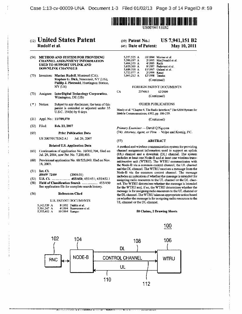
1
Case 1:13-cv-00009-UNA Document 1-3 Filed 01/02/13 Page 3 of 14 PagelD 59
1111111111111111 1111111111111111111il!J1111111111111111111111111(12) United States Patent (10) Patent No.: US 7,941, 151 B2
Rudolf et aL (45) Date of Patent: May 10, 2011
(54) METHOD AND SYSTEM FOR PROVIDING 5,357,525 A 10/1994 Moriue et al.
CHANNEL ASSIGNMENT INFORMATION 5,390, 197 A 2/1995 MacDonald et al.5,404, 355 A 4/1995 RaithUSED TO SUPPORT UPLINK AND5,659,569 A 8/1997 Padovani et al.
DOWNLLNK CHANNELSt 5,689,518 A 11/1997 Galand et al.
5,722,077 A 2/1998 Kanai(75) Inventors: Marian Rudolf, Montreal (CA); 5, 845,212 A 12/1998 Tanaka
Stephen G. Dick, Nesconset, NY (US); (Continued)Philip J. Pietraski, Huntington Station,NY (US) FOREIGN PATENT DOCUMENTS
CA 2374815 12/2000(73) Assignee: InterDigital Technology Corporation,
Wilmington, DE (US) (Continued)
Notice: Subject to any disclaimer, the term of this OTHER PUBLICATIONS
patent is extended or adjusted under 35Mouly et al. "Chapter 4, The Radio Interface, The GSM System for
U.S.C. 154(b) by 0 days. Mobile Communications; 4992, pp. 186-259.
(21) Appl. No.: 11/709,970 (Continued)
(22) Filed: Feb. 23, 2007Primary Examiner David Q Nguyen
(65) Prior Publication Data (74) Attorney, Agent, or Firm Volpe and Koenig, P.C.
US 2007/0173262 Al Jul. 26, 2007(57) ABSTRACT
Related U.S. Application Data A method and wireless communication system for providing(63) Continuation of application No. 10/902,704, filed on channel assignment information used to support an uplink
Jul. 29, 2004, now Pat. No. 7,200,405. (UL) channel and a downlink (DL) channel. The systemincludes at least one Node-B and at least one wireless trans-
(60) Provisional application No. 60/523,049, filed on Nov. mit/receive unit (WTRU). The WTRU communicates with18, 2003. the Node-B via a common control channel, the UL channel
and the DL channel. The WTRU receives a message from the(51) Int. Cl. Node-B via the common control channel. The messageHO4W 72100 (2009.01) includes an indication ofwhether the message is intended for(52) U.S. Cl. 455/450; 455/451; 455/452.1 assigning radio resources to the UL channel or the DL chan-(58) Field of Classification Search 455/450 nel. The WTRU determines whether the message is intendedI
i See application file for complete search history. for the WTRU and, ifso, the WTRU determines whether the
message is for assigning radio resources to the UL channel or(56) References Cited the DL channel. The WTRUtakes an appropriate action based
onwhether the message is for assigning radio resources to theU.S. PATENT DOCUMENTS UL channel or the DL channel.
5, 142, 539 A 8/1992 Dahlin et al.5,301,247 A 4/1994 Rasmussen et al.5,355,412 A 10/1994 Kangas 58 Claims, 2 Drawing Sheets
100
102 104 108 106
c DL
I Ric L...., NODE-B I CONTROL CHANNEL WTRU
UL
110112

Case 1:13-cv-00009-UNA Document 1-3 Filed 01/02/13 Page 4 of 14 PagelD 60
US 7,941,151 B2Page 2
U.S. PATENT DOCUMENTS Uplink for UTRA FDD (Release 6), 3GPP TR 25.896 V1.0.2 (Oct.
5,917,810 A 6/1999 De Bot 2003).5,917,840 A 6/1999 Cheney et al. Third Generation Partnership Project, "Technical Specification5,930,706 A 7/1999 Raith Group Radio Access Network; Feasibility Study for Enhanced
6,005,871 A 12/1999 Petersen et al. Uplink for UTRA FDD (Release 6), 3GPP TR 25.896 V6.0.0 (Mar.6, 134,597 A 10/2000 Rieth et al. 2004).6, 172,971 B1 1/2001 Kim "DL Control Channel Structures for Parameters Sent Simultaneously6,201,811 B1 3/2001 Larsson et al. With HS-DSCH rn." TSG-RAN WG1/WG2 Adhoc on HSDPA,6,424,632 B1 7/2002 Poret et al.6,430, 163 B1 8/2002 Mustajarvi et al. Sophia Antipolis, France, (Apr. 5-6, 2001).
6,735, 185 B1 5/2004 Noneman Balachandran et al., "Design of a Medium Access Control Feedback
6,850,509 B2 2/2005 Lee et al. Mechanism for Cellular TDMA Packet Data Systems", IEEE Journal
6,859,445 B1 2/2005 Moon et al. on Selected Areas in Communications, vol. 18, No. 9, pp. 1719-1730,6,882,727 B1 4/2005 Vialen et al. (Sep. 2000).6,901, 104 B1 5/2005 Du et al. 375/142 Gourgue, "Air Interface ofthe Future European Fully Digital Trunk6,915,473 B2 7/2005 Bolourchi et al.6,928,066 B1 8/2005 Moon et al.
Radio System", Proceedings of the Vehicular Technology Confer-
7,054,633 B2 5/2006 Seo et A. ence, vol. CONF. 43, pp. 714-717 (May 1993).7,079,848 B2 7/2006 Das et al, Interdigital Communication Corporation, "Implicit UE Identification
7, 181,298 B1 2/2007 Yoshio etal., for HSDPA Downlink Signaling", ;IDOC R1-01-0810, 3GPP RAN
7, 184,447 B1 2/2007 Koo et al. WG1 Meeting 22, (Aug. 2001), available at: http://www.3goo.org/7,200,788 B2 4/2007 Hiraki et al. ftp.tsg_ran/WGI_RL1.7,366, 105 B2 4/2008 Yi et A. Interdigital, "Updated Recommendation for UE-specific CRC",7,394,799 B2 7/2008 Li et al. TDOC R1-01-1066, 3GPP TSG RAN WG 1 AD HOC Meeting On7,558,228 B2 7/2009 Lee et al.7,693, 110 B2 4/2010 Love et al. HSDPA, (Nov. 2001), available at http://www.3gpp.org/ftp/tsg_ran/7,783,953 B2 8/2010 Bolourchi et al. WGI_RL1.
2002/0051431 Al 5/2002 Choi et al. Motorola, "Control Channel Structure for High Speed DSCH (HS-2002/0093918 Al 7/2002 Kim A al. DSCH), TSGR1#16(00) 1242, R2-12A010021, pp. 1-5 (Apr. 5-6,200210181422 AI 12/2002 Parantainen et al. 370/337 2001).2003/0219037 Al 11/2003 Toskala et al. 370/496 Third Generation Partnership Project, 'Technical Specification2004/0043783 Al 3/2004 Anderson Group Radio Access Network; High Speed Downlink Packet Access;2004/0085939 Al 5/2004 Boumendil et al. Overall UTRAN Description (Release 5), 3GPP TR 25.855 v0.0.3;2004/0085989 Al 5/2004 Boumendil et al. (May 2001).2010/0318886 Al 12/2010 Bolourchi et al. Third Generation Partnership Project, "Technical Specification
FOREIGN PATENT DOCUMENTS Group Radio Access Network; Feasibility Study for Enhanced
Uplink for UTRA FDD (Release 6), 3GPP TR 25.896V1.0.1, pp.16-DE 19855242 5/2000 21 (Oct. 2003).EP 1006670 6/2000 Third Generation Partnership Project, 'Technical SpecificationEP 1248476 10/2002EP 1324500 12/2002 Group Radio Access Network; High Speed Downlink Packet Access;
EP 1324500 7/2003 Overall UTRAN Description (Release 5), 3GPP TR 25.855 V5.0.0
EP 1351424 10/2003 (Sep. 2001).GB 2382956 12/2001 Third Generation Partnership Project, "Technical SpecificationGB 2383956 12/2001 Group Radio Access Network; Multiplexing and channel codingGB 2372409 8/2002 (FDD) (Release 1999), 3GPP TS 25.212 V3.5.0 (Dec. 2000).JP 01-196774 8/1989 Third Generation Partnership Project, "Technical SpecificationJP 05-236073 9/1993 Group Radio Access Network; Multiplexing and channel codingJP 08-316967 11/1996 (FDD) (Release 1999), 3GPP TS 25.212 V3.7.0 (Sep. 2001).JP 11-136138 5/1999 Third Generation Partnership Project, "Technical SpecificationJP 11-196070 7/1999TW 276382 5/1996 Group Radio Access Network; Multiplexing and channel coding
TW 276382 9/2005 (FDD) (Release 4), 3GPP TS 25.212 V4.2.0 (Sep. 2001).
WO 99/38076 7/1999 Third Generation Partnership Project, 'Technical SpecificationWO 00/21210 4/2000 Group Radio Access Network; Multiplexing and channel codingWO 00/28763 5/2000 (TDD) (Release 1999), 3GPP TS 25.222 V3.6.0 (Mar. 2001).WO 00/30378 5/2000 Third Generation Partnership Project, "Technical SpecificationWO 00/57660 9/2000 Group Radio Access Network; Multiplexing and channel codingWO 01/01609 1/2001 (TDD) (Release 4), 3GPP TS 25.222 V4.0.0 (Mar. 2001).WO 01/05050 1/2001 Third Generation Partnership Project, 'Technical SpecificationWO 02/51177 6/2002 Group Radio Access Network; Multiplexing and channel codingWO 02/096030 11/2002 (TDD) (Release 4), 3GPP TS 25.222 V4.1.0 (Sep. 2001).
Third Generation Partnership Project, 'Technical SpecificationOTHER PUBLICATIONS Group Radio Access Network; Multiplexing and channel coding
(TDD) (Release 1999), 3GPP TS 25.222 V3.7.0 (Sep. 2001).3GPP TSG RAN WG Tdoc R1-02-0018, Nokia, 'Compact Signal- Third Generation Partnership Project, 'Technical Specificationling of Multi-code Allocation for HSDPA, version 2, Espoo, Fin-
Group Radio Access Network; UTRAN Overall Descriptionland, Jan. 2002. (Release 1999), 3GPP TS 25.401 V3.6.0 (Mar. 2001).3GPP TSG RAN WG 1 Tdoc R1-02-1277, Noika, 'Two Threshold Third Generation Partnership Project, 'Technical SpecificationNode B Packet Scheduling, Shanghai, China, Nov. 2002. Group Radio Access Network; UTRAN Overall Description3GPP TSG RAN WG 1 Tdoc R1-02-1350, Motorola, "Design Con- (Release 1999), 3GPP TS 25.401 V3.8.0 (Sep. 2001).siderations for Enhanced Uplink Dedicated Channel, Shanghai, Third Generation Partnership Project, 'Technical SpecificationChina, Nov. 2002. Group Radio Access Network; UTRAN Overall Description3GPP TSG RAN WG 1 Tdoc R1-02-1277, Nokia, "Two Threshold (Release 4), 3GPP TS 25.401 V4.0.0 (Mar. 2001).Node B Packet Scheduling, Shanghai, China, Nov. 2002. Third Generation Partnership Project, 'Technical SpecificationThird Generation Partnership Project, "Technical Specification Group Radio Access Network; UTRAN Overall DescriptionGroup Radio Access Network; Feasibility Study for Enhanced (Release 4), 3GPP TS 25.401 V4.2.0 (Sep. 2001).
L. I MESTA ik Dir2C Irnnove. liPic/9n19

Case 1:13-cv-00009-UNA Document 1-3 Filed 01/02/13 Page 5 of 14 PagelD 61
US 7,941,151 B2Page 3
Third Generation Partnership Project, "Technical Specification Third Generation Partnership Project, "Technical SpecificationGroup Radio Access Network; UTRAN Overall Description Group Radio Access Network; Multiplexing and channel coding
(Release 5), 3GPP TS 25401 V5.1.0 (Sep. 2001). (TDD) (Release 5), 3GPP TS 25.222 V5.5.0 (Jun. 2003).Third Generation Partnership Project, "Technical SpecificationThird Generation Partnership Project, "Technical Specification Group Radio Access Network; Multiplexing and channel coding
Group Radio Access Network; UTRA High Speed Downlink Packet(TDD) (Release 5), 3GPP TS 25.212 V5.6.0 (Dec. 2003).
Access (HSDPA); Overall Description; Stage 2 (Release 5), 3GPP Third Generation Partnership Project, "Technical SpecificationTS 25.308 V5.0.0 (Sep. 2001). Group Radio Access Network; Multiplexing and channel codingThird Generation Partnership Project, 'Technical Specification (TDD) (Release 6), 3GPP TS 25.222 V6.0.0 (Dec. 2003).Group Radio Access Network; Physical channels and mapping of Third Generation Partnership Project, 'Technical Specificationtransport channels onto physical channels (TDD) (Release 1999), Group Radio Access Network; UTRAN Overall Description3GPP TS 25.221 V3.6.0 (Mar. 2001). (Release 1999), 3GPP TS 25.401 V3.10.0 (Jun. 2002).Third Generation Partnership Project, "Technical Specification Third Generation Partnership Project, 'Technical SpecificationGroup Radio Access Network; Physical channels and mapping of Group Radio Access Network; UTRAN Overall Descriptiontransport channels onto physical channels (TDD) (Release 1999), (Release 4), 3GPP TS 25.401 V4.6.0 (Dec. 2002).3GPP TS 25.221 V3.8.0 (Sep. 2001), Third Generation Partnership 'Project, 'Technical SpecificationThird Generation Partnership Project, "Technical Specification Group Radio Access Network; UTRAN Overall DescriptionGroup Radio Access Network; Physical channels and mapping of (Release 5), 3GPP TS 25.401 V5.6.0 (Jun. 2003).transport channels onto physical channels (TDD) (Release 4), 3GPP Third Generation Partnership Project, 'Technical SpecificationTS 25.221 V4.0.0 (Mar. 2001). Group Radio Access Network; UTRAN Overall DescriptionThird Generation Partnership Project, "Technical Specification (Release 5), 3GPP TS 25.401 V5.8.0 (Jun. 2004).Group Radio Access Network; Physical channels and mapping of Third Generation Partnership Project, "Technical Specificationtransport channels onto physical channels (TDD) (Release 4), 3GPP Group Radio Access Network; UTRAN Overall DescriptionTS 25.221 V4.2.0 (Sep. 2001). (Release 6), 3GPP TS 25.401 V6.1.0 (Jun. 2003).
1 Third Generation Partnership Project, "Technical Specification Third Generation Partnership Project, "Technical Specificationi Group Radio Access Network; Physical Layer Procedures (FDD) Group Radio Access Network; UTRAN Overall Description
(Release 1999), 3GPP TS 25.214 v3.6.0 (Mar. 2001). (Release 6), 3GPP TS 25.401 V6.3.0 (Jun. 2004).Third Generartnerstion Pahip Project, "Technical Specification Third Generation Partnership Project, 'Technical SpecificationGroup Radio Access Network; Physical Layer Procedures (FDD) Group Radio Access Network; UTRA High Speed Downlink Packet(Release 1999), 3GPP TS 25.214 v3.8.0 (Sep. 2001). Access (HSDPA); Overall Description; Stage 2 (Release 5), 3GPPThird Generation Partnership Project, "Technical Specification TS 25.308 V5.4.0 (Mar. 2003).
+ Group Radio Access Network; Physical Layer Procedures (FDD) Third Generation Partnership Project, "Technical Specification(Release 4), 3GPP TS 25.214 v4.0.0 (Mar. 2001). Group Radio Access Network; UTRA High Speed Downlink Packet
E Third Generation Partnership Project, "Technical Specification Access (HSDPA); Overall Description; Stage 2 (Release 5), 3GPP
Group Radio Access Network; Physical Layer Procedures (FDD) TS 25.308 V5.5.0 (Mar. 2004).(Release 4), 3GPP TS 25.214 v4.2.0 (Sep. 2001). Third Generation Partnership Project, "Technical SpecificationThird Generation Partnershp Project, "Technical Specification Group Group Radio Access Network; UTRA High Speed Downlink PacketRadio Access Network; Multiplexing and channel coding (FDD) Access (HSDPA); Overall Description; Stage 2 (Release 6), 3GPP(Release 4), 3GPP TS 25.212 V4.0.0 (Dec. 2000). TS 25.308 V6.1.0 (Mar. 2004).3rd Generation Partnership Project; Technical Specification Group Third Generation Partnership Project, "Technical SpecificationRadio Access Network; Multiplexing and channel coding (Release Group Radio Access Network; Physical channels and mapping of8); 3GPP TS 36.212 V0.2.1 (Nov. 2006). transport channels onto physical channels (TDD) (Release 1999),3rd Generation Partnership Project; Technical Specification Group 3GPP TS 25.221 V3.11.0 (Sep. 2002).Radio Access Network; Physical layer procedures (Release 8); 3GPP Third Generation Partnership Project, 'Technical SpecificationTS 36.213 V0.2.1 (Oct. 2006). Group Radio Access Network; Physical channels and mapping ofThird Generation Partnership Project, "Technical Specification transport channels onto physical channels (TDD) (Release 4), 3GPP
Group Radio Access Network; Multiplexing and channel coding TS 25.221 V4.7.0 (Dec. 2002).(FDD) (Release 1999), 3GPP TS 25.212 V3.11.0 (Sep. 2002). Third Generation Partnership Project, 'Technical SpecificationThird Generation Partnership Project, "Technical Specification Group Radio Access Network; Physical channels and mapping ofGroup Radio Access Network; Multiplexing and channel coding transport channels onto physical channels (TDD) (Release 5),"3GPP(FDD) (Release 4), 3GPP TS 25.212 V4.6.0 (Sep. 2002). TS 25.221 V5.5.0 (Jun. 2003).Third Generation Partnership Project, "Technical Specification Third Generation Partnership Project, 'Technical SpecificationGroup Radio Access Network; Multiplexing and channel coding Group Radio Access Network; Physical channels and mapping of(FDD) (Release 5), 3GPP TS 25.212 V5.6.0 (Sep. 2003). transport channels onto physical channels (TDD) (Release 6), 3GPPThird Generation Partnership Project, "Technical Specification TS 25.221 V6.1.0 (Jun. 2004).Group Radio Access Network; Multiplexing and channel coding Third Generation Partnership Project, 'Technical Specification(FDD) (Release 5), 3GPP TS 25.212 V5.9.0 (Jun. 2004). Group Radio Access Network; Physical Layer Procedures (FDD)Third Generation Partnership Project, "Technical Specification (Release 1999), 3GPP TS 25.214 v3.12.0 (Mar. 2003).Group Radio Access Network; Multiplexing and channel coding Third Generation Partnership Project, 'Technical Specification(FDD) (Release 6), 3GPP TS 25.212 V6.2.0 (Jun. 2004). Group Radio Access Network; Physical Layer Procedures (FDD)Third Generation Partnership Project, 'Technical Specification (Release 4), 3GPP TS 25.214 v4.6.0 (Mar. 2003).Group Radio Access Network; Multiplexing and channel coding Third Generation Partnership Project, 'Technical Specification(TDD) (Release 1999), 3GPP TS 25.222 V3.10.0 (Sep. 2002). Group Radio Access Network; Physical Layer Procedures (FDD)Third Generation Partnership Project, "Technical Specification (Release 5), 3GPP TS 25.214 v5.6.0 (Sep. 2003).Group Radio Access Network; Multiplexing and channel coding Third Generation Partnership Project, "Technical Specification(TDD) (Release 4), 3GPP TS 25.222 V4.6.0 (Dec. 2002). Group Radio Access Network; Physical Layer Procedures (FDD)Third Generation Partnership Project, "Technical Specification (Release 5)." 3GPP TS 25.214 v5.9.0 (Jun. 2004).Group Radio Access Network; Multiplexing and channel coding(TDD) (Release 4), 3GPP TS 25.222 V4.7.0 (Dec. 2003). a cited by examiner
1•••••••••••••• AI- nine, 4 4 14 Cinn4
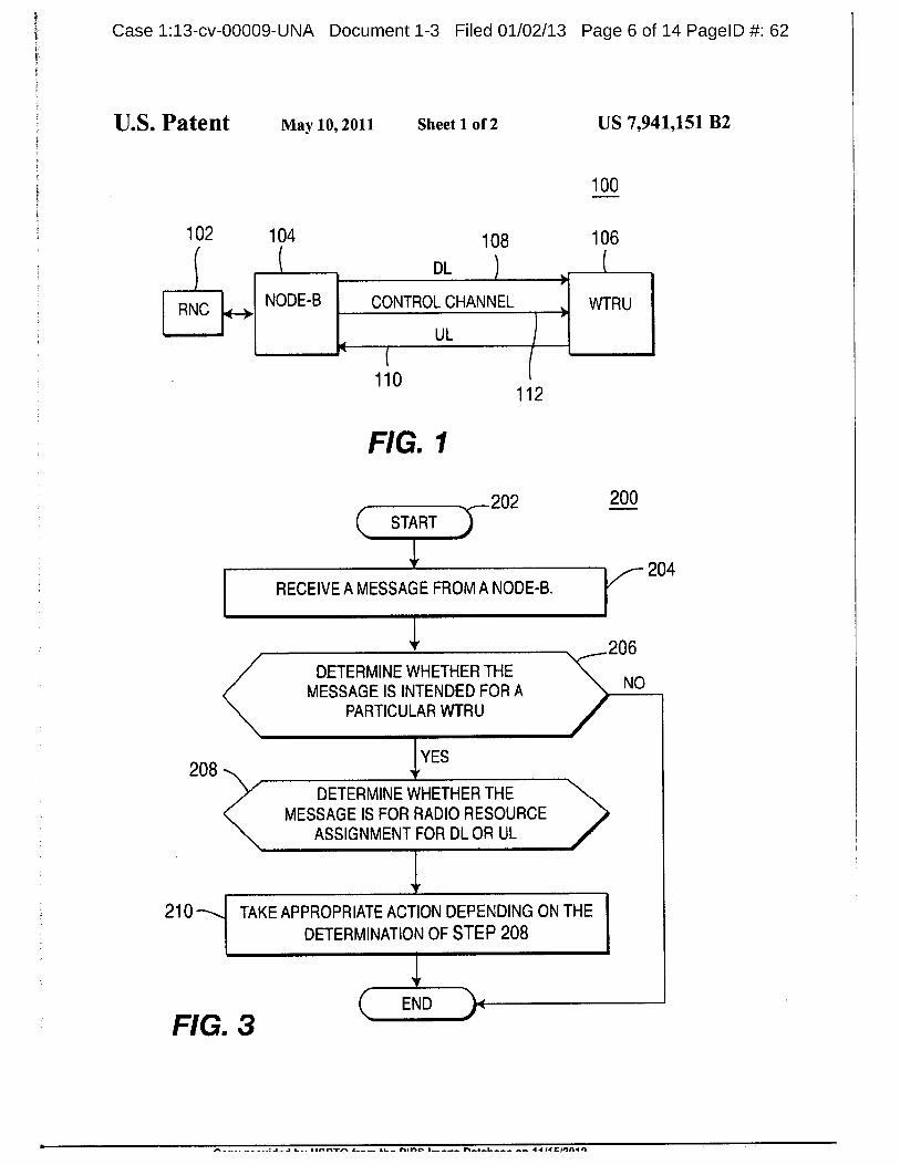
Case 1:13-cv-00009-UNA Document 1-3 Filed 01/02/13 Page 6 of 14 PagelD 62
U.S. Patent May 10, 2011 Sheet 1 of 2 US 7,941,151 B2
100
102 104 108 106
DL
RNC NODE-B CONTROL CHANNEL WTRU
ULIt
110112
FIG. 1
202 200START
RECEIVE A MESSAGE FROM A NODE-B.204
KDETERMINE WHETHER THE
MESSAGE IS INTENDED FOR A NO
PARTICULAR WTRU
YES208 w
DETERMINE WHETHER THEMESSAGE IS FOR RADIO RESOURCE
ASSIGNMENT FOR DL OR UL
Y
210 TAKE APPROPRIATE ACTION DEPENDING ON THE
DETERMINATION OF STEP 208
V
END )4FIG. 3
nlet 44 /4 einnin
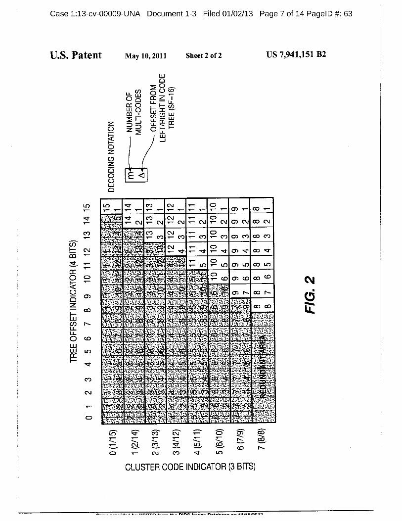
Case 1:13-cv-00009-UNA Document 1-3 Filed 01/02/13 Page 7 of 14 PagelD 63
U.S. Patent May 10, 2011 Sheet 2 of 2 US 7,941,151 B2
2 01.1._ o 0 to
o ict, zcc o i-75
0cf 0 Lu
17-7 LL I-UZ0 Z 02
0 E
0
tr) in -zzi- co C., 7— 001 co1-
-r;:i.., •zr CO CV 1- CDI--,-L-r---V-.- I-- CV I-- CV I-- CV N- CV T-- CV 0) C\I CO CV
CO i-T-7--t t 7",_Iji's CO CV 1- CD„95b,t,1
42.Cr) 1- CO 1- CO, CY) 0) CO CO CO
cpciI— C\I 140114.4w 11641, I,, I, '7
zi., 7-- rtg a rail:,,-.J1-1 iiii:'hib, LO 1- LO 0) LC) CO LO
c,'rt.:late. IVII.Ve, M1-Ji...41 ;1171-41.tgi ttO.Ve7•4 7- CID 0) (0 C° C° 01111
r '4.. li,V1 ^Ip 111.V1 0 11.V1 1•11 VIA.1.1; V11.V .5; ;C. 1410 1TrA Nri..ere .14tii;\+-r, JqjiN-i; 42.jr)ii—t 707.11-rt—' ol N- co N-
C) u...-,..u........)... J._ u...-, ...1., A...N0.1, Is 7,J.-..- J.:, J.
L-I CDZ 11.2.7.12va /12:-.4-1.:::1- /12::1.27.:1 ;42.,:42.* :.112.;:a...V Tit:7 co in't2. 'f_0:iFil riA.:: f'N# :17:1:10,71,. .:M TQF;17 -rt_T-, c° C°
r- 42,1.-0-r- .r-i-r, -r '-i4r,--iv-,-1 1-1-1v,I.,..0,3
cn N- r i 44-1"-°.. -"-Nr -t --'i'llit-4 tjt't.t't t -I° tjPFD- frt-'Frie vi-vryLI- II
LI- ii,Viiljr't 7-7-1-1-t t st-t "t-t -1 't-t "t-t -t -1-1 't -1 1- t "t-t t- "t-t 17g st-t t-ti t-i.,.a.1. 1, e,4 k...1,,,,,,1,
0 cs) r'-e-rsijist -riji-7-7 st- st-t i,...r.T.-1-1.1 rIV-SIF-1 r/V11-1.jr- 7-1=:tivr ::r..7-2:11'-'1 4r*T:':"*T.11 .1-v1-2:".1j 1.:TI.PrT a.U-1 LO .4k0r-s CA]. to Wrt .42 0. 4,E,
I—.4- ligislifti rtr; ....--;'/I''
t,,, ..f....; t:.... -t., tv, .k. k...,.
t-r) rtsi.;11-140. rtsAiiik.."; -11- T.1-, 44,7:-.J., ..s. -....k, k, .k
1.., 1...........+0. 1...1...1 .......+1.....", ...I...1. ..+1 1....... 1 1
riii41Ya., -m2:-,,,.!o.;,,ia-,,44.4,1.1 1.1., •..1.6.1.1 ..1,-1.1, ..1 .;.1.1..1.1.6.1. 1%4.1, 11" ..-1,11.-sis.., 1.1-4,..1-4•1.6..t, ..1r.c.1.
T..... re-1.4. Iti...71.6., s .V.V.6-T, ..7.^t.al.Z.31: TI.Ifil."- 'APE, 1.- NI; 1:.' 11.21BEC)t=
CO CV 0 01 CO
COCV CO -tzt° LO
CO N-O 1- CV CO •:t
CLUSTER CODE INDICATOR (3 BITS)
I-AL.- ar.rrres s.---- LL.. none 1111C/01140
Case 1:13-cv-00009-UNA Document 1-3 Filed 01/02/13 Page 8 of 14 PagelD 64
US 7,941, 151 B21 2
METHOD AND SYSTEM FOR PROVIDING introduced on top of an existing HS-SCCH for an HSDPA.
CHANNEL ASSIGNMENT INFORMATION Thus, it is possible to introduce a separate set ofSF-128 DL
USED TO SUPPORT UPLINK AND channels as UL resource assignment channels. With this
DOWNLINK CHANNELS approach, a WTRU would be required to monitor one or more
5 UL resource assignment channels in addition to theCROSS REFERENCE TO RELATED HS-SCCHs for an HSDPA operation. Althoughthis approach
APPLICATION is conceptually simple, there are many disadvantages withthis scheme, such as WTRU complexity, WTRU battery effi-
This application is a continuation of U.S. patent applica- ciency, and DL spreading code usage.tion Ser. No. 10/902,704, filed Jul. 29, 2004 now U.S. Pat. No. 10 Therefore, an efficient EU channel assignment scheme is
7,200,405, which claims the benefit of U.S. Provisional necessary for supporting both an EU and an HSDPA operaApplication No. 60/523,049 filed on Nov. 18, 2003, which is tion.
incorporated by reference as if fully set forth.SUMMARY
FIELD OF INVENTION 15
In one embodiment, the present invention is a method andThe present invention is related to a wireless communica- wireless communication system for providing channel
tion system. Moreparticularly, the present invention is mlated assignment information for supporting a UL channel and a
to a method and system for providing channel assignment DL channel. The system includes at least one Node-B and at
information to support uplink and downlink transmissions. 20 least one WTRU. The WTRU communicates withthe Node-Bvia a common control channel, the 1JL channel and the DL
BACKGROUND channel. The WTRU receives a message from the Node-B viathe common control channel. The message includes an indi-
High speed downlink packet access (HSDPA) has been cation ofwhether the message is intended for assigning radio
developed to increase downlink (DL) efficiency and through- 25 resources to the UL channel or the DL channel. The WTRU
put in universal mobile telecommunication system (UMTS) determines whether the message is intended for the WTRURelease 5 (R5) wideband code division multiple access and, ifso, the WTRU determines whether the message is for(W-CDMA) systems. The key advantages ofHSDPA as com- assigning radio resources to the UL channel or the DL chan-
pared to UMTS R991R4 are fast and dynamic link adaptation nel. TheWTRU takes an appropriate actionbased on whetherin the DL and a fast layer 1 hybrid automatic repeat request 30 the message is for assigning radio resources to the UL channel(H-ARQ). Fast link adaptation is achieved by fast scheduling or the DL channel.DL transmissions in a base station, coupled with fast layer 1 In another embodiment, the present invention is a methodDL signaling channels. The signaling channel, a high speed and time-slottedwireless communication system. The systemshared control channel (HS-SCCH), conveys radio resource includes at least one Node-B, a radio network controllerallocation information to a plurality of wireless transmit/ 35 (RNC) which controls the Node-B, and at least one WTRUreceive units (WTRUs). which communicates with the Node-B via a common control
ln frequency division duplex (FDD), an HS-SCCH is sent channel, a UL channel and a DL channel. The RNC transmitsby means ofa spreading factor (SF)=-128 channelization code a message to the WTRU indicating which time slot TTIs
during a three (3) time slot transmission time interval (TTI). support UL channel transmissions and which time slot TTlsThe HS-SCCH indicates that data would be transmitted to a ao support DL channel transmissions.WTRU on a high speed downlink shared channel (HS-DSCH) after a particular time offset. The HS-SCCH carries BRIEF DESCRIPTION OF THE DRAWINGSthe following information: 1) channelization-code-set infor-mation (7 bits); 2) modulation scheme information (1 bit); 3) A moredetailed understanding ofthe invention may be had
transport-block size information (6 bits); 4) H-ARQ process as from the following description ofa preferred example, giveninformation (3 bits); 5) redundancy and constellation version by way of example and to be understood in conjunction with
(3 bits); 6) new data indicator (1 bit); and 7) a WTRU identity the accompanying drawing wherein:
(16 bits). FIG. 1 is a block diagram of a wireless communicationThe HS-SCCH is sent over three (3) time slots (2 ms TTI), system operating in accordance with the present invention;
but consists of two (2) fields. Field 1 (first time slot) contains 50 FIG. 2 is a look-up table for channelization code set map-channelization code mapping and modulation format infor- ping in an HSDPA, which is utilized in conjunction with the
mation; and field 2 (second and third time slots) contains system of FIG. 1; and
transport block size, H-ARQ information, redundancy ver- FIG. 3 is a flowchart of a process including method stepssion and a new data indicator along with a WTRU-specific for implementing uplink channPl assignment signaling in
cyclic redundancy check (CRC). 55 accordance with the present invention.
Alternatively, an enhanced uplink (EU) increases uplink(UL) efficiency and throughput. H-ARQ and Node-B sched- DETAILED DESCRIPTION OF THE PREFERRED
uling is part ofthe EU. Similar to an HSDPA, a new shared DL EMBODIMENTScontrol channel for EU operation provides fast and dynamicallocation of 1JL radio resources for UL transmissions. The so The present invention will be described with reference to
shared DL control channel for the EU needs to ensure low the drawing figures wherein like numerals represent like ele-
allocation latencies and efficient radio resources management ments throughout.for UL transmissions. Hereinafter, the shared DL control Hereafter, the terminology "WTRU" includes but is not
channel for the purposes of an EU is simply referred to as a limited to a user equipment, a mobile station, a fixed or
1JL resource assigAment channel. 65 mobile subscriber unit, a pager, or any other type of device
In order to implement an EU along with an HSDPA, capable of operating in a wireless environment. When
another UL resource assignment channel for the EU could be referred to hereafter, the terminology "Node-B" includes but
A A. r•ler) 11 PI CMII1n
3 4
Case 1:13-cv-00009-UNA Document 1-3 Filed 01/02/13 Page 9 of 14 PagelD 65
US 7,941, 151 B2
is not limited to a base station, a site controller, an access point assignment of radio resources for UL transmission, rather
or any other type of interfacing device in a wireless environ- than DL transmission, or that the codes corresponding to the
ment. channelization-code-set are assigned to UL transmissions.The present invention is applicable to any type ofwireless In accordance with a second embodiment of the present
communication systems such as UMTS-time division duplex 5 invention, an indication that a particular radio resource is
(TDD) and FDD, time division synchronous code division assigned for UL transmission is provided by means of a
multiple access (TDSCDMA), code division multiple access WTRU-specific CRC. Under current HSDPA specifications,2000 (CDMA 2000), and CDMA in general or any other type a WTRU-specific CRC is contained inan HS-SCCH field 2.A
ofwireless communication system. 16-bit CRC is computed from the information to be transmit-
The features of the present invention may be incorporated 10 ted, and the computed CRC is masked with a unique 16-bit
into an integrated circuit (IC) or be configured in a circuit WTRU identity (ID). The masked CRC is transmitted to a
comprising a multitude of interconnecting components. WTRU 106 as a WTRU-specific CRC.
The present invention will be described in reference to an In accordance with the second embodiment of the presentHSDPA and an EU, and the terms HSDPA and EU are used invention, this WTRU-specific CRC is modified in a uniqueinterchangeably with DL and UL, respectively. However, it is and deterministic way to indicate that the demodulated trans-
should be understood that the reference to an HSDPA and an mission is for UL transmission, rather than DL transmission.EU is just for describing the preferred embodiment of the For example, a WTRU-specific CRC computed for an
present invention, and the teachings of the present invention HSDPA is inverted for an EU before performing a channel
may be applied to any system for utilizing a common control coding. A WTRU 106 performs two (2) different compari-channel for transmitting channel assignment information for 20 sons, preferably simultaneously, in performing a CRC of the
both UL and DL transmissions simultaneously. received transmission. If the WTRU 106 succeeds in decod-FIG. 1 is a block diagram of a system 100 for supporting ing the received transmission with a WTRU-specific CRC,
UL and DL operations in accordance with the present inven- the WTRU 106 reco nizes that the transmission is intendedtion. The system 100 includes an RNC 102, a Node-B 104, for an HSDPA, and if the WTRU 106 succeeds in decodingand a WTRU 106. The Node-B 104 is controlled by the RNC 25 the received transmission with an inverted WTRU-specific102, and dynamically allocates radio resources for both UL CRC, the WTRU 106 recognizes that the transmission is
and DL transmissions from and to the WTRU 106. Three intended for an EU.channels are established between the Node-B 104 and the In accordance with a third embodiment of the presentWTRU 106. The channels are a DL channel 108, a UL chan- invention, an indication that a particular radio resource is
nel 110, and a common control channel 112. The common 30 assigned for an EU is provided by means ofa WTRU-specificcontrol channel 112 is utilized for transmission of channel masking sequence. Under current HSDPA specifications, a
assignment information for both UL and DL transmissions. 40-bit sequence of field 1 is masked with a 40-bit WTRU-
The Node-B 104 is configured to support an HSDPA and specific intermediate code sequence which is generated from
EU operation. Therefore, each Node-B 104 dynamically allo- a 16-bit WTRU ID.cates radio resources for DL and UL transmissions to and 35 In accordance with the third embodiment, the WTRU-
from the WTRU 106 through an HS-DSCH and an EU chan- specific masking on field 1 is modified in a unique and deter-
nel, respectively. The radio resources assignment information ministic way to indicate that a transmission is intended for an
for both the HS-DSCH and the EU is transmitted through the EU, not for an HSDPA. For example, the inverted 16-bit CRC
common control channel 112. generated in the second embodiment may be used to derive
In accordance with the present invention, the common 40 the 40-bit long masking sequence. Ifthe WTRU 106 succeeds
control channel 112 is utilized for the transmission of radio in decoding the received transmission with a WTRU-specificresources assignment information for both UL and DL trans- masking sequence, the WTRU 106 recognizes that the trans-
missions and a specific indication is provided to distinguish mission is intended for an HSDPA, and if the WTRU 106
whether the radio resource assignment is for either UL or DL succeeds in decoding the received transmission with an
transmission. Therefore, the common control channel 112 45 inverted WTRU-specific masking sequence, the WTRU 106
occupies a shared DL radio resource space, as definedby a set recognizes that the transmission is intended for an EU.of SF=128 channelization codes, for both DL and UL trans- With this method, theWTRU 106 can make the distinction
missions simultaneously, and the WTRU 106 is configured to whether an EU or an HSDPA channel assignment has been
recognize whether a particular transmission is intended for transmitted after having received only field 1 of the HS-
assigning radio resources for the DL or the UL transmissions. so SCCH transmission.In accordance with a first embodiment ofthe present inven- Alternatively, WTRU IDs are allocated by the network in
tion, an indication that a particular radio resource is assigned such a way that a particular WTRU ID does not collide with
for a UL transmission is provided by means ofone ormore of anotherWTRU ID. For example, a first WTRU's inverted IDthe impossible combinations in the channelization code set for EU may be used to indicate a second WTRU's HSDPA
mapping in a current HSDPA. FIG. 2 is a look-up table for 55 service. Therefore, simultaneous detection of presence of a
channelization code set mapping currently used in the UL resource assignment channel and an HS-SCCH is facili-
HSDPA. An HS-SCCH uses seven (7) bits to inform the tated.WTRU 106 which SF=16 channelization codes are used for In accordance with a fourth embodiment of the presentthe corresponding HS-DSCH. Out of the 128 possible com- invention, an indication that a particular radio resource is
binations, eight (8) combinations are not currently used in an 60 assigned for an EU is provided by means of radio resource
HSDPA (see the labeled "redundant area" in FIG. 2). One or control (RRC) context signaling. Preferably, a Node-B 104
more ofthe eight (8) unused combinations is used for assign- allocates separate radio resources for transmission of UL
ing radio resources or indicating that the demodulated trans- radio resources assignment and DL radio resources assign-mission is for UL transmission, not DL transmission. There- ment. Alternatively, an RNC 102 allocates separate radio
fore, ifthe WTRU 106 determines that a channelization-code- 65 resources for transmission ofUL radio resources assignmentset corresponds to one ofthe impossible combinations ofFIG. and DL radio resources assigament by using RRC signaling2, the WTRU 106 recognizes that the transmission is for messages.
P I.... I ite•rvrrs •t-- CHOC .4 CPIAI
Case 1:13-cv-00009-UNA Document 1-3 Filed 01/02/13 Page 10 of 14 PagelD 66
US 7,941, 151 B2
5 6For example, an RRC signaling message from the RNC the WTRU determining whether the downlink control
102 may inform a WTRU 106 in which TTIs to expect an information is intended for the WTRU based on WTRU
HS-SCCH or a UL resource assignment channel. Under cur- identity (ID)-masked cyclic redundancy check (CRC)rent R5 HSDPA specifications, fifteen (15) time slots include parity bits, and if so determining whether the channel
one (1) frame, and three (3) time slots include one (1) TTI. 5 assignment information is for assigning radio resources
"Even" TrIs may include, for example, time slots 2, 4, 6, 8, for the uplink shared channel or the downlink shared
10, 12 and 14, and "odd" TTIs may include, for example, time channel; andslots 1, 3, 5, 7, 9, 11, 13 and 15. the WTRU utilizing the radio resources for the uplink
In accordance with the present invention, an RRC transmits shared channel or the downlink shared channel.
signals indicating that a transmission in "even" TTIs is for an to 2. The method of claim 1, wherein the WTRU ID-masked
HS-SCCH and a transmission in "odd" TrIs is for a UL CRC parity bits are derived from a sixteen bit CRC.
resource assignment channel. By not allowing a transmission 3. The method of claim 1, wherein the downlink control
for an HS-SCCH to be transmitted in "odd" TTIs, backwards information includes modulation and coding scheme infor-
compatibility with R5 WTRUs can be ensured. The same set mation.of SF=128 resources can be used for an HS-SCCH and a UL 15 4. The method of claim 1, wherein the downlink control
resource assignment channel. information includes a new data indicator.
ln accordance with a fifth embodiment of the present 5. The method of claim 1, wherein the downlink control
invention, an indication that a particular radio resource is information includes a redundancy version.
assigned for an EU is provided by means of layer 1 indication 6. The method of claim 1, wherein the downlink control
on an associated DL dedicated channel (DCH). One or more 20 information includes hybrid automatic repeat requestbits on the associated DL DCH are used to indicate imminent (H-ARQ) information.
occurrence of a UL resource assignment channel as opposed 7. The method of claim 1, wherein the physical downlink
to an HS-SCCH by means of a fixed and pre-determined control channel is a common channel.
timing relationship. 8. The method of claim 1, wherein the physical downlink
FIG. 3 is a flowchart of a process 200 including method 25 control channel carries both downlink and uplink channel
steps for implementing UL channel assignment signaling in assignment information simultaneously.accordance with the present invention. After the process 200 9. The method of claim 1, wherein the downlink control
is initiated (step 202), a message for radio resource assign- information indicates whether the channel assignment infor-
ment is transmitted via a common control channel from a mation is for the uplink shared channel or the downlink
Node-B 104 to a WTRU 106. The WTRU 106 receives and 30 shared channel.demodulates the message using predetermined codes every 10. The method of claim 1, wherein the determination of
predetermined TTI, for example, every 2 ms (step 204). The whether the channel assignment information is for assigningWTRU 106 then determines ifthe message is intended for the radio resources for the uplink shared channel or the downlink
WTRU 106 (step 206). A WTRU-specific CRC may be uti- shared channel is basedon the WTRU ID-masked CRC paritylized for this purpose. If the WTRU 106 determines that the 35 bits.
message is intended for the WTRU 106, the WTRU 106 11. The method of claim 1, wherein the determination of
determines whether the message is for the assignment of whether the channel assignment information is for assigningradio resources for DL transmission or UL transmission radio resources for the uplink shared channel or the downlink
implementing one of the embodiments of the present inven- shared channel is based on a WTRU-specific maskingtion described above (step 208). The WTRU 106 then takes ao sequence.appropriate actions (step 210) depending on the decision in 12. The method of claim 1, wherein the determination of
step 208 to receive or transmit data packet via DL or UL whether the channel assignment information is for assigningchannels. For example, the WTRU 106 may recognize radio resources for the uplink shared channel or the downlink
exactly when to initialize a data reception procedure via the shared channel is based on radio resource control (RRC)DL channel 108 or when to initialize a data transmission 45 signaling.procedure via the UL channel 110. Currently, an HS-SCCH 13. The method of claim 1, wherein the determination of
for an HSDPA announces an incoming data packet for the whether the channel assignment information is for assigningWTRU with a fixed two (2) slot offset, whereas the present radio resources for the uplink shared channel or the downlink
invention can inform the WTRU when it has an opportunity to shared channel is based on a transmit time interval.
transmit a packet via the UL, (e.g., four slots from now). so 14. The method of claim 1, wherein the determination of
While this invention has been particularly shown and whether the channel assignment information is for assigningdescribed with reference to preferred embodiments, it will be radio resources for the uplink shared channel or the downlink
understood by those skilled in the art that various changes in shared channel is based on at least one of the WTRU ID-
form and details may be made therein without departing from masked CRC parity bits, a WTRU-specific maskingthe scope of the invention described hereinabove. 55 sequence, radio resource control (RRC) signaling, or a trans-
mit time interval.What is claimed is: 15. The method of claim 1 wherein the downlink channel
1. A method for utilizing channel assignment information assignment information is carried in one time interval and the
for an uplink shared channel or a downlink shared channel, uplink channel assignment information is carried in another
the method comprising: 60 time interval.a wireless transmit/receive unit (WTRU) receiving down- 16. A wireless transmit/receive unit (WTRU) for utilizing
link control information including downlink or uplink channel assignment information for an uplink shared channel
channel assignment information via a same physical or a downlink shared channel, the WTRU comprising:downlink control channel, both downlink channel a receiver configured to receive downlink control informa
assignment information and uplink channel assignment 65 tion including downlink or uplink channel assignmentinformation being received via the same physical down- information via a same physical downlink control chan-
link control channel; nel, both downlink channel assignment information and
..e.r,ro, rSfl GI,1111,11

Case 1:13-cv-00009-UNA Document 1-3 Filed 01/02/13 Page 11 of 14 PagelD 67
US 7,941, 151 B2
7 8
uplink channel assignment information being received a scheduler for generating configured to generate channel
via the same physical downlink control channel; and assignment information to assign radio resources to the
a controller configured to determine whether the downlink WTRU for the uplink shared channel and or the down-
control information is intended for the WTRU based on link shared channel; and
WTRU identity (ID)-masked cyclic redundancy check 5 a transmitter for transmitting configured to transmit down-
(CRC) parity bits and to determine whether the channel link control information including uplink or downlink
assignment information is for assigning radio resources channel assignment information and WTRU identityfor the uplink shared channel or the downlink shared (ID)-masked cyclic redundancy check (CRC) parity bits
channel, and utiliiing the radio resources for the uplink to the WTRU via a same physical downlink control
shared channel or the downlink shared channel. 10 channel, both downlink channel assignment information
17. The WTRU of claim 16, wherein the WTRU and uplink channel assignment infonnation being trans-
ID-masked CRC parity bits are derived from a sixteen bit mitted via the same physical downlink control channel,CRC. the downlink control information including an indica-
18. The WTRU ofclaim 16, wherein the downlink control15
tion indicating whether the channel assignment infor-
information includes modulation and coding scheme infor- mation is for assigning the radio resources for the uplinkmation. shared channel or the downlink shared channel.
19. The WTRU ofclaim 16, wherein the downlink control 32. The Node-B of claim 31, wherein the WTRU ID-
information includes a new data indicator. masked CRC parity bits are derived from a sixteen bit CRC.
20. The WTRU ofclaim 16, wherein the downlink control 20 33. The Node-B ofclaim 31, wherein the downlink control
information includes a redundancy version. information includes modulation and coding scheme infor-
21. The WTRU ofclaim 16, wherein the downlink control mation.
information includes hybrid automatic repeat request 34. The Node-B ofclaim 31, wherein the downlink control
(H-ARQ) information. information includes a new data indicator.
22. The WTRU ofclaim 16, wherein the physical downlink 25 35. The Node-B ofclaim 31, wherein the downlink control
control channel is a common channel. information includes a redundancy version.
23. The WTRU ofclaim 16, wherein thephysical downlink 36. The Node-B ofclaim 31, wherein the downlink control
control channel carries both downlink and uplink channel information includes hybrid automatic repeat requestassignment information simultaneously. (H-ARQ) information.
24. The WTRU ofclaim 16, wherein the downlink control 30 37. The Node-B of claim 31, wherein the physical down-
information indicates whether the channel assignment infor- link control channel is a common channel.
mation is for the uplink shared channel or the downlink 38. The Node-B of claim 31, wherein the physical down-
shared channel. link control channel carries bothdownlinkand uplinkchannel
25. The WIRU ofclaim 16, wherein the determination of assignment information simultaneously.whether the channel assignment information is for assigning 35 39. The Node-B of claim 31, wherein the indicatingradio resources for the uplink shared channel or the downlink whether the channel assignment information is for assigningshared channel is based on theWTRU ID-masked CRC parity the radio resources for the uplink shared channel or downlink
bits. shared channel is based on the WTRU ID-masked CRC parity26. The WTRU ofclaim 16, wherein the determination of bits.
whether the channel assignment information is for assigning ao 40. The Node-B of claim 31, wherein the indicatingradio resources for the uplink shared channel or the downlink whether the channel assignment information is for assigningshared channel is based on a WTRU-specific masking the radio resources for the uplinkshared channel or downlink
sequence. shared channel is based on a WTRU-specific masking27. The WTRU ofclaim 16, wherein the determination of sequence.
whether the channel assignment information is for assigning 45 41. The Node-B of claim 31, wherein the indicatingradio resources for the uplink shared channel or the downlink whether the channel assignment information is for assigningshared channel is based on radio resource control (RRC) the radio resources for the uplinkshared channel or downlink
signaling, shared channel is based on radio resource control (RRC)28. The WTRU of claim 16, wherein the determination of signaling.
whether the channel assignment information is for assigning so 42. The Node-B of claim 31, wherein the indicatingradio resources for the uplink shared channel or the downlink whether the channel assignment information is for assigningshared channel is based on a transmit time interval, the radio resources for the uplink shared channel or downlink
29. The WTRU of claim 16, wherein the determination of shared channel is based on a transmit time interval.
whether the channel assignment information is for assigning 43. The Node-B of claim 31, wherein the indicatingradio resources for the uplink shared channel or the downlink 55 whether the channel assignment information is for assigningshared channel is based on at least one of the WTRU ID- the radio resources for theuplink shared channel or downlink
masked CRC parity bits, a WTRU-specific masking shared channel is based on at least one of the WTRU ID-
sequence, radio resource control (RRC) signaling, or a trans- masked CRC parity bits, a WTRU-specific maskingmit time interval, sequence, radio resource control (RRC) signaling, or a trans-
30. The WTRU ofclaim 16 wherein the downlink channel 60 mit time interval.
assignment information is carried in one time interval and the 44. The Node-B ofclaim 31 wherein the downlink channel
uplink channel assigament information is carried in another assignment information is carried in one time interval and the
time interval. uplink channel assignment information is carried in another
31. A Node-B for selectively providing channel assign- time interval.
ment information to a wireless transmit/receive unit (WTRU) 65 45. A method for providing channel assignment informa-
for an uplink shared channel and or a downlink shared chan- tion for an uplink shared channel or a downlink shared chan-
nel, the Node-B comprising: nel via a downlink control channel, the method comprising:
aLA 113110e IlnintsnazA 11/1R/9f119
Case 1:13-cv-00009-UNA Document 1-3 Filed 01/02/13 Page 12 of 14 PagelD 68
US 7,941, 151 B2
9 10a Node B generating channel assignment information to 53. The method of claim 45, wherein the indicating
assign radio resources to a wireless transmit/receive unit whether the channel assignment information is for assigning(WTRU) for the uplink shared channel or the downlink the radio resources for the uplink shared channel or downlinkshared channel; and shared channel is based on the WTRU ID-masked CRC parity
the Node B transmitting downlink control information 5 bits.including uplink or downlink channel assignment infor- 54. The method of claim 45, wherein the indicatingmation and WTRU identity (ID)-masked cyclic redun- whether the channel assignment information is for assigningdancy check (CRC) parity bits to the WTRU via a same the radio resources for the uplink shared channel or downlinkphysical downlink control channel, both downlink chan- shared channel is based on a WTRU-specific maskingnel assignment information and uplink channel assign-
io sequence.ment information being transmitted via the same physi- 55. The method of claim 45, wherein the indicatingcal downlink control channel, the downlink control
whether the channel assignment information is for assigninginformation including an indication indicating whether
the radio resources for the uplink shared channel or downlinkthe channel assignment information is for assigning the
shared channel is based on radio resource control (RRC)radio resources for the uplink shared channel or thedownlink shared channel. 15 signaling.
46. The method of claim 45, wherein the WTRU 56. The method of claim 45, wherein the indicatingID-masked CRC parity bits are derived from a sixteen bit whether the channel assignment information is for assigningCRC. the radio resources for the uplinkshared channel or downlink
47. The method ofclaim 45, wherein the downlink control shared channel is based on a transmit time interval.
information includes modulation and coding scheme infor_ 20 57. The method of claim 45, wherein the indicatingmation. whether the channel assignment information is for assigning
48. The method of claim 45, wherein the downlink control the radio resources for the uplinkshared channel or downlink
information includes a new data indicator. shared channel is based on at least one of the WTRU ID-
49. The method of claim 45, wherein the downlink control masked CRC parity bits, a WTRU-specific maskinginformation includes a redundancy version. 25 sequence, radio resource control (RRC) signaling, or a trans
50. The method ofclaim 45, wherein the downlink control mit time interval.
information includes hybrid automatic repeat request 58. The method ofclaim 45 wherein the downlink channel
(H-ARQ) information, assignment information is carried in one time interval and the
51. The method ofclaim 45, wherein the physical downlink uplink channel assignment information is carried in another
control channel is a common channel. 30 time interval.
52. The method ofclaim 45, wherein the physical downlinkcontrol channel carries both downlink and uplink channel
assignment information simultaneously.
_a ir•errs moo 11 /1 APIA19

Case 1:13-cv-00009-UNA Document 1-3 Filed 01/02/13 Page 13 of 14 PagelD 69
UNITED STATES PATENT AND TRADEMARK OFFICE
CERTIFICATE OF CORRECTION
PATENTNO.: 7,941, 151 B2 Page 1 of 2
APPLICATION NO.: 11/709970DATED: May 10, 2011
INVENTOR(S): Rudolf et al.
It is certified that error appears in the above-identified patent and that said Letters Patent is hereby corrected as shown below:
ON THE TITLE PAGE
Item (75) "Inventors:" delete "Phillip" and insert --Philip--.
Item (63) "Related U.S. Application Data", delete "10/902,704" and insert --10/902,740--.
Item (56) U.S. PATENT DOCUMENTS, page 2, left column, after "2004/0043783 Al 3/2004
Anderson", delete "2004/0085939 Al 5/2004 Boumendil et al.".
Item (56) FOREIGN PATENT DOCUMENTS, page 2, left column, after "EP 1248476 10/2002",
delete "EP 1324500 12/2002".
Item (56) FOREIGN PATENT DOCUMENTS, page 2, left column, after "GB 2382956 12/2001",
delete "GB 2383956 12/2001".
Item (56) FOREIGN PATENT DOCUMENTS, page 2, left column, after "TW 276382 5/1996",
delete "TW 276382 9/2005".
Item (56) OTHER PUBLICATIONS, page 2, left column, after "R1-02-1277, delete "Noika, and
insert --Nokia,
Item (56) OTHER PUBLICATIONS, page 2, right column, after "WGI Meeting 22, (Aug. 2001)available at http://www", delete ".3goo." and insert --.3gpp.--.
Item (56) OTHER PUBLICATIONS, page 3, right column, after "(Release 5), 3GPP TS", delete
"25.212" and insert --25.222--.
Signed and Sealed this
Twenty-seventh Day of December, 2011
r/1144, 7*etDavid J. Kappos
Director ofthe United States Patent and Trademark Office
I morn 4k,. DIOC irnften. nainhaan nn 11 /15/21:112
Case 1:13-cv-00009-UNA Document 1-3 Filed 01/02/13 Page 14 of 14 PagelD 70
CERTIFICATE OF CORRECTION (continued) Page 2 of 2
U.S. Pat. No. 7,941,151 B2
IN THE SPECIFICATION
At column 1, line 10, after "Ser. No." delete "10/902,704" and insert --10/902,740--.
IN THE CLAIMS
At Claim 31, colunm 7, line 64, after "Node-B for", delete "selectively"
At Claim 31, column 7, line 66, after "shared channel", delete "and".
At Claim 31, column 8, line 1, after "a scheduler" delete "for generating".
At Claim 31, column 8, line 3, after "shared channel", delete "and".
At Claim 31, column 8, line 5, after "a transmitter", delete "for transmitting".
Wilminoton DE 19801
IV. NATURE OF SUIT (Place an "X" in One Box Only)
II 2 r R. 971
Foreign Country
Case 1:13-cv-00009-UNA Document 1-4 Filed 01/02/13 Page 1 of 2 PagelD 71%.JS 44 (Rev. 12/07) CIVIL COVER SHEETThe JS 44 civil cover sheet and the information contained herein neither replace nor supplement the filing and service ofpleadings orother papers as required lay law, except as providedby local rules ofcourt. This form, approved by the Judicial Conference of the United States in September 1974, is required for the use ofthe Clerk ofCourt for the purpose ofinitiatingthe civil docket sheet. (SEE INSTRUCTIONS ON THE REVERSE OF THE FORM.)
I. (a) PLAINTIFFS DEFENDANTSInterDigital Communications, Inc., InterDigital Technology Corporation, IPR ZTE Corporation and ZTE (USA) Inc.
Licensing, Inc. and InterDigital Holdings, Inc.
(b) County ofResidence ofFirst Listed Plaintiff County ofResidence ofFirst Listed Defendant
(EXCEPT IN U.S. PLAINTIFF CASES) (IN U.S, PLAINTIFF CASES ONLY)NOTE: IN LAND CONDEMNATION CASES, USETHE LOCATION OF THE
LAND INVOLVED.
Attorney's (Firm Name, Address, and Telephone Number) Attorneys (IfKnown)Neal. Beigam (tf 2721)Proctor Heyman LLP, 300 Delaware Avenue, Suite 200,
II. BASIS OF JURISDICTION (Place an "X" in One Box Only) III. CITIZENSHIP OF PRINCIPAL PARTIES(Place an "X" in One Box for Plaintiff
(For Diversity Cases Only) and One Box for Defendant)O 1 U.S. Government NI 3 Federal Question PH' DEE PTE. DEF
Plaintiff (U.S. Government Not a Party) Citizen ofThis State B 1 CI I Incorporated or Principal Place 0 4 0 4of Business In This State
3 2 U.S. Government 0 4 Diversity Citizen of Another State 0 2 0 2 Incorporated andPrincipal Place 0 5 0 5
Defendant of Business In Another State(Indicate Citizenship ofParties in Item III)
Citizen or Subject ofa 0 3 CI 3 ForeignNation 0 6 0 6
7•10,2 .Vt„, ...Attg q:LZA.E:1V.W.AlfrA9Z-ri:, .1001Mena", M: Z r ob.. ts 4, 57.v.70Kl";•,•_••!....1, .11:33 Z.4 DfA n:',, „1,,,I, _L.-.1-41;=:1,-...listElia,...d r i I r "s-,-.17111-ils '1 L..,.1:144....T. ur h: a
3 110 Insurance PERSONAL INJURY PERSONAL INJURY 0 610 Agriculture 0 422 Appeal 28 USC 158 0 400 State Reapportionment3 120 Marine 0 310 Airplane 0 362 Personal Injury 0 620 Other Food & Drug 0 423 Withdrawal 0 410 Antitrust
3 130 Miller Act 0 315 Airplane Product Med. Malpractice 0 625 Drug Related Seizure 28 USC 157 0 430 Banks and BankingO 140 Negotiable Instrument Liability 0 365 Personal Injwy of Property 21 USC 881 0 450 Commerce
3 150 Recovery ofOverpayment 0 320 Assault, Libel & Product Liability 0 630 Liquor Laws Pl:171Ki't. e‘i:., tilelliK9.;;-.....ilzi, 0 460 Deportation&Enforcementofludgment Slander CI 368 Asbestos Personal 0 640 R.R. & Truck 0 820 Copyrights 0 470 Racketeer Influenced and
3 151 Medicare Act 0 330 Federal Employers' Injury Product 0 650 Airline Regs. lg 830 Patent Coirupt OrganizationsI 152 Recovery ofDefaulted Liability Liability 0 660 Occupational 0 840 Trademark 0 480 Consumer Credit
Student Loans 0 340 Marine PERSONAL PROPERTY Safety/Health 0 490 Cable/Sat TV
(Excl. Veterans) 0 345 Marine Product 0 370 Other Fraud 0 690 Other 0 810 Selective Service
-20 153 Recovery ofOverpayment Liability 0 371 Truth in Lending 10M_,tir,,Pi _i.,,.'...412r., al :t.....1.1.3ftejt.v..I..,1 t il in 850 Secinities/Commodities/
of Veteran's Benefits 0 350 Motor Vehicle 0 380 Other Personal 0 710 Fair Labor Standards 0 861 HIA (1395ff) Exchange'1 160 Stockholders' Suits 0 355 Motor Vehicle Property Damage Act 0 862 Black Lung (923) a 875 Customer ChallengeO 190 Other Contract Product Liability 0 385 Property Damage 0 720 Labor/Mgmt. Relations CI 863 DIWC/DIWW (405(g)) 12 USC 3410
O 195 Contract Product Liability 0 360 Other Personal Product Liability 0 730 Labor/MgmtReporting 0 864 SSID Title XVI CI 890 Other Statutory Actions
O 196 Franchise In & Disclosure Act CI 865 RSI 405 0 891 Agricultural Acts
kilir i7lTZ 01' GPM:V...7k .71-,. r.'LLLA Niel 4 411.1:1";`, ..a r: t.,1;4v..1.:': D.i..., ;io a toil cov.::., o 74c Railway Labor Act :-..i• :ri Num: -i.lriii ..is•:<ii, I.. :LA-, CI 892 Economic Stabilization Act
CI 210 Land Condemnation 0 441 Voting 0 510 Motions to Vacate 0 790 Oiher Labor Litigation 0 870 Taxes (U.S. Plaintiff 0 893 Environmental Matters
0 220 Foreclosure CI 142 Employment Sentence 0 791 Empl. Ret Inc. or Defendant) 0 894 Energy Allocation Act
0 230 Rent Lease & Ejectment 0 443 Housing/ Habeas Corpus: Security Act 0 871 IRS—Third Party Cil 895 Freedom ofInformation
0 240 Torts to Land Accommodations CI 530 General 26 USC 7609 Act
0 245 Tort Product Liability El 444 Welfare 0 535 Death Penalty =W.V.'. 1-, ...f.v FiNV,,,. B 900Appeal orFee Determination
il 290 All Other Real Property 0 445 Amer. w/Disabilities CI 540 Mandamus & Other 0 462 Naturalization Application Under Equal Access
Employment 0 550 Civi/ Rights 0 463 Habeas Corpus to Justice
O 446 Amer, w/Disabilities 0 555 Prison Condition Alien Detainee 0 950 Constitutionality of
Other 3 465 Other Immigration State Statutes
O 440 Other Civil Rights Actions
V. ORIGIN (Place an "X" in One Box Only) Apge frompeal to District
CR 1 Original El 2 Removed from n ci 5 Transferred from3 Remanded from 4 Reinstated or CI 6 Multidistrict D 7 Ju
another district M.agistrateProceeding State Court Appellate Court Reopened L(specify) itigation Judgment
Cite the U.S. Civil Statute under which you are filing (Do not cite jurisdictional statutes unless diversity)
VI. CAUSE OF ACTION 'Birief descripton ofcause:
PatRnt infrinnnmpnt
VII. REQUESTED IN II CHECK IF THE Is A CLASS AcnoN DEMAND CHECK Y P,S only it demanded in complaint.
COMPLAINT: UNDER F.R.C.P, 23 JURY DEMAND: a Yes 0 No
VIII. RELATED cAsE(S) One of four cases filed on January 2, 2013 by Plaintiffs sharing common patents.(See instructions): DOCKET NUMBER 1: 11-cv-00654-RGAIF ANY JUDGE Judge Richard G. AndrewsAlso related to:
DATE SIGNATURE OF ATTORNEY OF RECORD
0110212013 Is/ Neal C. BelgamFOR OFFICE USE ONLY
RECEIPT 6 AMOUNT APPLYING IFP JUDGE MAG. JUDGE
Case 1:13-cv-00009-UNA Document 1-4 Filed 01/02/13 Page 2 of 2 PagelD 72
JS 44 Reverse (Rev. 12107)
INSTRUCTIONS FOR ATTORNEYS COMPLETING CWIL COVER SHEET FORM iS 44
Authority For Civil Cover Sheet
The JS 44 civil cover sheet and the information contained herein neither replaces nor supplements the filings and service ofpleading or other papers as requiredby law, except as provided by local rules of court. This form, approved hy the Judicial Conference ofthe United States in September 1974, is required for the use
ofthe Clerk ofCourt for the purpose ofinitiating the civil docket sheet. Consequently, a civil cover sheet is submitted to the Clerk ofCourt for each civil complaintfiled. The attorney filing a case should complete the fonn as follows:
I. (a) PIaintiffs-Defendants. Enter names (last, first, middle initial) ofplaintiffand defendant. Ifthe plaintiffor defendant is a government agency, use onlythe full name or standard abbreviations. Ifthe plaintiffor defendant is an official within a govennnent agency, identify first the agency and then the official, givingboth name and title.
(b) County ofResidence. For each civil case filed, except U.S. plaintiffcases, enter the name ofthe county where the first listed plaintiff resides at the time
of filing. In U.S. plaintiff cases, enter the name of the county in which the first listed defendant resides at the time offiling. (NOTE: In land condemnation cases,
the county ofresidence of the "defendant" is the location of the tract of land involved.)
(c) Attorneys. Enter the firm name, address, telephone number, and attorney ofrecord. Ifthere are several attorneys, list them on an attachment, noting
in this section "(see attachment)".B. Jurisdiction. The basis ofjurisdiction is set forth under Rule 8(a), F.R.C.P., which requires thatjurisdictions be shown in pleadings. Place an "X" in one
of the boxes. If there is more than one basis ofjurisdiction, precedence is given in the order shown below.
United States plaintiff. (1) Jurisdiction based on 28 U.S.C. 1345 and 1348. Suits by agencies and officers of the United States are included here.
United States defendant. (2) When the plaintiff is suing the United States, its officers or agencies, place an "X" in this box.
Federal question. (3) This refers to suits under 28 U.S.C. 1331, where jurisdiction arises under the Constitution of the United States, an amendment to the
Constitution, an act ofCongress or a treaty of the United States. In cases where the U.S. is a party, the U.S. plaintiffor defendant code takes precedence, and box
1 or 2 should be marked.
Diversity ofcitizenship. (4) This refers to suits under 28 U.S.C. 1332, where parties are citizens ofdifferent states. When Box 4 is checked, the citizenship ofthe
different parties must be checked. (See Section III below; federal question actions take precedence over diversity cases.)
III. Residence (citizenship) ofPrincipal Parties. This section ofthe JS 44 is to be completed ifdiversity ofcitizenship was indicated above. Mark this section
for each principal party.IV. Nature ofSuit Place an "X" in the appropriate box. Ifthe nature ofsuit cannot he determined, be sure the cause ofaction, in Section VI below, is sufficient
to enable the deputy clerk or the statistical clerks in the Administrative Office to determine the nature ofsuit. Ifthe cause fits more than one nature of suit, select
the most definitive.
V. Origin. Place an "X" in one of the seven boxes.
Original Proceedings. (1) Cases which originate in the United States district courts.
Removed from State Court. (2) Proceedings initiated in state courts may be removed to the district courts under Title 28 U.S.C., Section 1441. When the petitionfor removal is granted, check this box.
Remanded from Appellate Court. (3) Check this box for cases remanded to the district court for further action. Use the date of remand as the filing date.
Reinstated or Reopened. (4) Check this box for cases reinstated or reopened in the district court. Use the reopening date as the filing date.
Transferred from Another District. (5) For cases transferred under Title 28 U.S.C. Section 1404(a). Do not use this for within district transfers or multidistrict
litigation transfers.
Multidistrict Litigation. (6) Check this box when a multidistrict case is transferred into the district under authority ofTitle 28 U.S.C. Section 1407. When this box
is checked, do not check (5) above.
Appeal to District Judge from Magistrate Judgment. (7) Check this box for an appeal from a magistrate judge's decision.
VI. Cause ofAction. Report the civil statute directly related to the cause ofaction and give a briefdescription ofthe cause. Do not cite jurisdictional statutes
unless diversity. Example: U.S. Civil Statute: 47 USC 553Brief Description: Unauthorized reception ofcable service
VII. Requested in Complaint. Class Action. Place an "X" in this box ifyou are filing a class action under Rule 23, F.R.Cv.P.
Demand. In this space enter the dollar amount (in thousands ofdollars) being demanded or indicate other demand such as a preliminary injunction.
Jury Demand. Check the appropriate box to indicate whether or not a jury is being demanded.
VIII. Related Cases. This section of the JS 44 is used to reference related pending cases if any. If there are related pending cases, insert the docket numbers
and the corresponding judge names for such cases.
Date and Attorney Signature. Date and sign the civil cover sheet.