Embed Size (px)
Citation preview

Author's personal copy
Interaction of dynamic mode-I cracks with inclined interfaces
V.B. Chalivendra a,*, A.J. Rosakis b
a Department of Mechanical Engineering, University of Massachusetts Dartmouth, 285 Old Westport Road,
North Dartmouth, MA 02747, USAb Graduate Aeronautical Laboratories, California Institute of Technology, Pasadena, CA 91125, USA
Received 15 February 2007; received in revised form 6 August 2007; accepted 7 August 2007Available online 17 August 2007
Abstract
In this paper, we report on an experimental study of the deflection/penetration behavior of dynamic mode-I crackspropagating at two different crack velocities (slower and faster) toward inclined weak interfaces of three dissimilar angles(a): 30�, 45� and 60�. A simple wedge-loading specimen configuration as proposed by Xu et al. [Xu LR, Huang YY,Rosakis AJ. Dynamic crack deflection and penetration at interface in homogenous materials: experimental studies andmodel predictions. J Mech Phys Solids 2003;51:461–86], made of brittle Homalite-100, is used. A modified Hopkinsonbar setup is used to achieve well-controlled impact loading conditions. Dynamic photoelasticity in conjunction withhigh-speed photography is used to capture real-time isochromatics associated with deflected/penetrated cracks.� 2007 Elsevier Ltd. All rights reserved.
Keywords: Dynamic fracture; Inclined interfaces; Crack deflection and penetration; Dynamic photoelasticity; High-speed photography
1. Introduction
Cracks usually propagate in homogeneous, brittle solids under locally mode-I conditions, at sub-Rayleighwave speeds (CR) typically below the crack branching speed [1,2]. Even though the crack accelerates underincreasing far-field loading, it reaches a critical speed beyond which it becomes energetically more favorableto propagate with multiple, branched crack tips rather than as a single entity. However if a crack is consideredto propagate along a weak path, the weak path traps the crack, suppressing any tendency of branching orkinking out of the weak plane and permits very fast crack growth approaching the Rayleigh wave speed ofthe parent material [3,4]. However, when the mode-II cracks are made to propagate along such weak paths,they tend to go even faster, with speeds that are within the intersonic regime of the solid [4–6].
Literature reveals that extreme mode-I and mode-II cases have been studied both experimentally and the-oretically. However, little has been reported about the dynamic mixed-mode crack growth along weak paths.Geubelle and Kubair [6] reported the transition of an incident mode-I crack into a mixed-mode crack as it
0013-7944/$ - see front matter � 2007 Elsevier Ltd. All rights reserved.
doi:10.1016/j.engfracmech.2007.08.005
* Corresponding author. Tel.: +1 508 910 6572; fax: +1 508 999 8881.E-mail address: [email protected] (V.B. Chalivendra).
Available online at www.sciencedirect.com
Engineering Fracture Mechanics 75 (2008) 2385–2397
www.elsevier.com/locate/engfracmech
Author's personal copy
come across a weak plane or interface. Xu and Rosakis [7] experimentally observed the transition of subsonicmode-I cracks after approaching the interface, propagating as shear-dominated interface cracks at intersonicspeeds. Recently Xu et al. [8] also experimentally observed a speed jump or dramatic speed increase as thecrack transitions from a purely mode-I crack to an unstable mixed-mode interfacial crack. In their paper, theycompared experimental speed jump phenomenon with theoretical predictions based on energy criterion. Theyalso discussed the deflection behavior of mode-I cracks (propagating in Homalite-100 material) upon reachingthe inclined interfaces of various strengths and different inclined interface angles. It is appropriate to mentionhere that numerous research efforts have been reported on static deflection/penetration behavior at an inter-face in the past years for various kinds of materials [9–17].
This paper presents an extension of the experimental work reported by Xu et al. [8]. In their paper, theyinvestigated only one case of incipient mode-I crack speed, which is slightly less than the critical or branchingspeed of Homalite-100 material (0.35–0.4CR). In real-life situations, the materials are made out of severalbonded substrates, as is the case with fiber reinforced composites, semiconductor materials, and layered mate-rials in airplanes. As reported above, the cracks can propagate at much higher speeds approaching Rayleighwave speeds along the weak planes or interfaces of these layered materials. Since interfaces are usually weakerthan the constituent materials, their interface failure under dynamic loading conditions is the active failuremechanism in such solids [18]. Indeed any defects in such interfaces can ultimately serve as sites of catastrophicfailure nucleation during the service life of the structure.
Motivated by the above real-life situations of layered materials, this experimental study is conducted toinvestigate the deflection/penetration behavior that occurs when an incipient mode-I crack propagating at aspeed close to 0.8–0.9CR approaches the inclined weak interface. The deflection/penetration behavior of fastermode-I cracks is also compared with that of slower cracks. The experiments in slower crack speed are repeatedin this study for comparison purposes. Similar to Xu et al. [8], weakly bonded material systems composed ofidentical constituent solids are considered so that the resulting material remains constitutively homogeneous.However, the existence of weak bonds (bonds of lower fracture toughness) makes this material system inho-mogeneous regarding its fracture toughness behavior. This avoids the complication of the material propertyand wave speed mismatch across the interface, while maintaining the essential properties of a weak path orbond whose strength can be experimentally varied. In contrast to the loading setup used by Xu et al. [8], amodified Hopkinson bar setup is used to have well-controlled dynamic loading of the specimen. The loadinghistories of each specimen are recorded using strain gages bonded onto the notch faces of the specimen. Thisfacilitates proper comparison of the results of various specimen configurations with similar loading conditions.
The organization of the paper is as follows. A brief description of experimental setup including specimenconfigurations used for two different mode-I crack tip speeds, a loading setup and a dynamic photoelasticsetup is given in Section 2. In Section 3, experimental results for specimens of three different inclined interfaceorientation angles are presented. Finally, in Section 4, a summary of the results of this study is discussed.
2. Experimental procedures
A novel wedge-loaded plate specimen configuration proposed by Xu et al. [8] is used to produce a single andstraight dynamic mode-I crack. Two specimen configurations used in this study to obtain different mode-Icrack tip speeds are shown in Fig. 1. The major advantage of dynamic wedge-loading is the fact that it gen-erates a negative non-singular stress, which enhances the crack path stability and prevents branching [19].These specimens were made out of Homalite-100, which is a brittle bifringent material. Homalite-100 was cho-sen because its mechanical properties, wave speeds and dynamic fracture behavior have been well-documentedin the literature [20]. Some of the physical properties of Homalite-100 are given in Table 1. The wave speedsare measured using ultrasonics while the rest of the properties are taken from the literature. The overall dimen-sions of the specimens are 475 · 380 · 9.5 mm3. The reason for choosing such large specimen dimensions is toprevent the effect of reflected waves arriving from the free boundaries on both mode-I and mixed mode crackpropagation within the range of field of interest. The field of interest considered in this study is a circle with adiameter of 125 mm, as shown in Fig. 2. Three different interfacial angles (a = 30�, 45� and 60�) are consideredin this study. To create weak interfacial bond strength, Loctite-384 adhesive is used to bond the interfaces. The
2386 V.B. Chalivendra, A.J. Rosakis / Engineering Fracture Mechanics 75 (2008) 2385–2397

Author's personal copy
adhesive quasi-static fracture toughness is 0.35 MPa m1/2 when it is used to bond two Homalite-100 plates.The average thickness of the adhesive layer is less than 100 lm.
In Fig. 1a, the specimen is designed to have mode-I crack propagation in Homalite-100 material with aspeed ranging from 0.35CR–0.4CR, i.e. slightly below the crack branching speed. However, in the case of aspecimen of Fig. 1b, the cracks can achieve speeds as high as 0.75CR–0.8CR. It can be noticed that two dif-ferent horizontal crack propagation lengths, 25 mm and 50 mm, are used, respectively, in the Fig. 1a and b.The reason for choosing different horizontal crack propagation lengths in these two specimen configurations isto have almost similar loading conditions when the crack approaches the inclined interface. Since the fastercrack propagates at almost twice the speed of the slower crack, the horizontal crack propagation length ofFig. 1b is increased to twice of that of Fig. 1a.
As mentioned in the introduction of this paper, a loading setup based on a modified Hopkinson barapparatus is used to dynamically load the specimens. The diagram of the loading setup is shown in Fig. 2.The loading setup consists of a steel bar, a steel projectile and a steel wedge. This loading setup provides
380 mm
457
mm
Interfaceα
(a)
Interface
(b)
α
25 mm 50 mm
Fig. 1. Specimen configurations.
Table 1Optical and mechanical properties of Homalite-100 used in this study
Property Value
Young’s modulus E (MPa) 3860Poisson’s ratio m 0.35Material fringe constant fr (kN/m) 23.6Dilatational wave speed CP (km/s) 2.104Shear wave speed CS (km/s) 1.2Density q (kg/m3) 1230
Steel Projectile
Strain gage rosette
Steel bar Strain gage
Supports
InterfaceSteel wedge
Field of interest of 125mm diameter
Fig. 2. Modified Hopkinson bar loading setup.
V.B. Chalivendra, A.J. Rosakis / Engineering Fracture Mechanics 75 (2008) 2385–2397 2387

Author's personal copy
well-controlled dynamic loading conditions, which can be monitored by bonding a strain gage onto the Hop-kinson bar. A steel wedge is inserted into the notch of the specimen. The specimen with the wedge is heldagainst the bar without any gap. A gas gun is used to impact the Hopkinson bar with a 50 mm long steel pro-jectile. The impact generates a compressive pulse which passes through the bar and wedge. This pulse loads thenotch faces of the specimen while passing through the wedge. A set of strain gage rosettes are attached at adistance of 4 mm away from the notch faces. These rosettes record the strain values associated with the load-ing pulses. Using plane stress conditions, the strain pulses are later analyzed to obtain normal stress and shearstress pulses. Typical normal and shear stress pulses obtained from the strain gage rosettes are shown in Fig. 3.As given in the figure, the range of arrival times of mode-I cracks at the inclined interface is 70–80 ls for allexperiments reported in this paper. The variation of normal and shear stresses due to applied dynamic loadingwithin this arrival time range is very small, therefore the comparison of experiments with in this time range isacceptable. As reported in Fig. 3, the stress pulses are almost symmetric in all of the experiments reported inthis paper.
-30
-25
-20
-15
-10
-5
0
5
0 50 100 150 200 250 300 350
Time (μs)
Stre
ss (
MPa
)
Shear stress pulses
Normal stress pulses
top gage
bottom gage
top gagebottom gage
Range of arrival times of the mode-ICrack tips at inclined interface = 70-80μs
Fig. 3. Typical normal and shear loading pulses.
Fig. 4. Dynamic Photoelastic experimental setup.
2388 V.B. Chalivendra, A.J. Rosakis / Engineering Fracture Mechanics 75 (2008) 2385–2397
Author's personal copy
The other important part of the experimental setup is the dynamic photoelasticity setup as shown in Fig. 4.It consists of a laser light source, a set of circular polarizer sheets, and a high-speed camera. A collimated beamis used to illuminate the specimen, which is sandwiched between the two circular polarizer sheets. The high-speed camera is used to capture the photoelastic fringes associated with a propagating crack. The high-speedcamera system is able to capture the images at a framing rate of 100 million frames per second with exposuretimes as low as 10 ns. In this study, the high-speed camera is operated at a much slower speed, around 0.2–0.4million frames per second.
3. Experimental observations
As discussed in the introduction, for proper comparison of the results of various specimen configurationswith similar loading conditions, a constant projectile speed of 20–22 m/s was chosen. Dynamic photoelasticityin conjunction with high-speed photography provides full-field information in terms of isochromatics of real-time crack propagation. This information provides valid data regarding crack tip position, crack tip velocityand the deflection/penetration behavior of a mode-I crack upon reaching the inclined interface. The followingsections discuss these observations for specimens of each inclined interface angle, a = 30�, 45� and 60�.
3.1. Specimens of inclined interface angle, a = 30�
A set of isochromatic fringe patterns associated with dynamic crack propagation for two specimen con-figurations of a = 30� is shown in Fig. 5. The time (t) values mentioned in this figure and other figures show-
Fig. 5. Isochromatics associated with a propagating crack for an inclined interface, a = 30� (the black circular spot in the figuresrepresents a scale of 6.25 mm).
V.B. Chalivendra, A.J. Rosakis / Engineering Fracture Mechanics 75 (2008) 2385–2397 2389

Author's personal copy
ing isochromtatics in this paper are timing values after the initiation of the dynamic loading on notch facesof the specimen. The black circular spot shown in all figures is a scaling mark of 6.25 mm in diameter. Asshown in Fig. 5a, the mode-I crack tip of the specimen (t = 40 ls) without horizontal interface can be clearlyidentified by the bigger shadow spot corresponding to a traveling stress singularity as well as from theincreased concentration of focused isochromatics at the crack tip. However, the shadow spot associated withthe mode-I crack of the specimen (t = 45 ls) corresponding to the horizontal interface shown in Fig. 5b issmall due to the fact that the propagating toughness of a weak interface is much smaller compared to thepropagating toughness of the Homalite-100. For the specimen in Fig. 5a and b, the mode-I crack reaches theinclined interface at around 70 ls and 78 ls, respectively. For both cases in Fig. 5, the isochromatic fringesassociated with propagating cracks along inclined interfaces have a similar pattern except for a small differ-ence in size of the fringes. The asymmetry in fringe patterns of the inclined interfacial cracks represents theexistence of mode-mixity.
The crack tip velocity vs. time records for both specimen configurations of a = 30� are shown in Fig. 6. Fora specimen without horizontal interface, the mode-I crack propagates at an average velocity of 384 m/s beforereaching the inclined interface. However, as reported by Xu et al. [8] the crack jumps to a much higher velocitywhen it is deflected onto a weak inclined interface. The average crack tip velocity along the inclined interfacefor this specimen configuration is around 917 m/s. In the case of a specimen with a horizontal interface, forsimilar loading conditions, the mode-I crack propagates at an average velocity of 720 m/s without any branch-ing. The weak interface or path suppresses any micro-branching while the crack is propagating and lets thecrack propagate at much higher mode-I crack speeds than the branching speed of Homalite-100 material. Sur-prisingly this crack tip does not jump to a much higher speed that is similar to previous specimen configurationafter reaching the inclined interface. It propagates with the same average velocity (714 m/s) along the inclinedinterface. It seems that the mode-I crack, which is propagating along the horizontal interface, has not expe-rienced any change in fracture resistance when deflected to propagate along the inclined interface of a = 30�. Itcan also be noted from the Fig. 6 that the crack slows down when it is propagating along an inclined interface.
0
100
200
300
400
500
600
700
800
900
1000
0 20 40 60 80 100 120 140 160 180 200
Time (μs)
Cra
ck ti
p ve
loci
ty (
m/s
)
Without Horizontal interface
With Horizontal interface
Arrival times of the crack tips at the inclined interface ≈ 70 & 78 μs
Fig. 6. Crack tip velocity history of a propagating crack for an inclined interface, a = 30�.
2390 V.B. Chalivendra, A.J. Rosakis / Engineering Fracture Mechanics 75 (2008) 2385–2397
Author's personal copy
The reason for this reduction in crack velocity is that as the crack propagates further on the inclined interface,it moves away from loading points, i.e., notch faces.
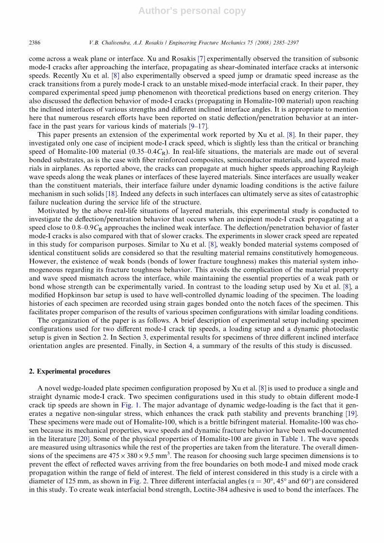
As shown in Fig. 5a and b, for the frames of t = 130 ls and t = 135 ls, respectively, the mode-I crack hasclear deflection without any penetration. It is observed for the specimens of other inclination angles that ifthe crack penetrates while it deflects, it does so approximately at right angle to the inclined interface. Asreported by Rosakis et al. [18], when a mixed-mode crack propagates along the weak interface, it generatesmicro-cracks (along the tensile side of shear) within the process zone of crack tip. These micro-tensile cracksbecome bigger when the loading conditions are favorable to them. The angle of these tensile cracks is usu-ally dependent on crack tip stress conditions and more importantly non-singular stress or T-stress actinghorizontal to the crack line. Therefore for a = 30�, the penetration angle of tensile crack would be approx-imately 60� as shown in Fig. 7a. It seems that the resistance to penetration at this angle is much higher forboth mode-I crack tip velocities. This finding is reinforced by the fact that no micro-cracks are observed onthe tensile side of the interface for specimens of a = 30�. Even the applied impact loading is increased by50% for specimen configuration with horizontal interface; there are no penetration attempts for inclinationangle of a = 30�.
α = 30o
60o
(a) α = 30o
Mode-I crack of both velocities
Deflected mixed- mode crack
No penetratedcrack
α = 45o
45o
(b2) α = 45o
Mode-I crack of higher velocity
Deflected mixed- mode crack
No penetratedcrack
α = 60o
30o
(c) α = 60o
Mode-I crack of both velocities
Deflected mixed- mode crack
Penetratedcrack
α = 45o
45o
(b1) α = 45o
Mode-I crack of lower velocity
Deflected mixed- mode crack
Penetratedcrack
Fig. 7. Schematic diagram showing the deflection/penetration behavior of incoming mode-I crack when it reaches inclined interface.
V.B. Chalivendra, A.J. Rosakis / Engineering Fracture Mechanics 75 (2008) 2385–2397 2391
Author's personal copy
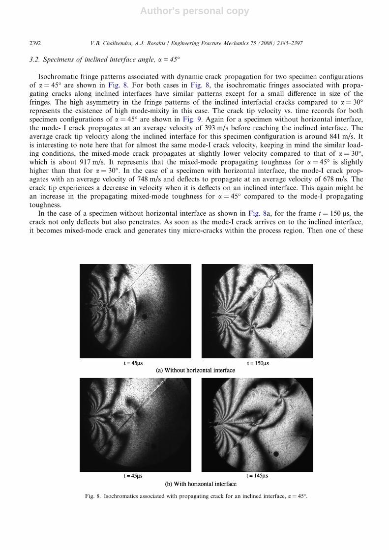
3.2. Specimens of inclined interface angle, a = 45�
Isochromatic fringe patterns associated with dynamic crack propagation for two specimen configurationsof a = 45� are shown in Fig. 8. For both cases in Fig. 8, the isochromatic fringes associated with propa-gating cracks along inclined interfaces have similar patterns except for a small difference in size of thefringes. The high asymmetry in the fringe patterns of the inclined interfacial cracks compared to a = 30�represents the existence of high mode-mixity in this case. The crack tip velocity vs. time records for bothspecimen configurations of a = 45� are shown in Fig. 9. Again for a specimen without horizontal interface,the mode- I crack propagates at an average velocity of 393 m/s before reaching the inclined interface. Theaverage crack tip velocity along the inclined interface for this specimen configuration is around 841 m/s. Itis interesting to note here that for almost the same mode-I crack velocity, keeping in mind the similar load-ing conditions, the mixed-mode crack propagates at slightly lower velocity compared to that of a = 30�,which is about 917 m/s. It represents that the mixed-mode propagating toughness for a = 45� is slightlyhigher than that for a = 30�. In the case of a specimen with horizontal interface, the mode-I crack prop-agates with an average velocity of 748 m/s and deflects to propagate at an average velocity of 678 m/s. Thecrack tip experiences a decrease in velocity when it is deflects on an inclined interface. This again might bean increase in the propagating mixed-mode toughness for a = 45� compared to the mode-I propagatingtoughness.
In the case of a specimen without horizontal interface as shown in Fig. 8a, for the frame t = 150 ls, thecrack not only deflects but also penetrates. As soon as the mode-I crack arrives on to the inclined interface,it becomes mixed-mode crack and generates tiny micro-cracks within the process region. Then one of these
Fig. 8. Isochromatics associated with propagating crack for an inclined interface, a = 45�.
2392 V.B. Chalivendra, A.J. Rosakis / Engineering Fracture Mechanics 75 (2008) 2385–2397

Author's personal copy
micro-cracks become a big crack and propagates with very small delay compared to the main deflected crack.The details of the delay of penetrated crack with respect to deflected crack can be seen in the Fig. 10. The pen-etrated crack propagates with an average velocity of 350 m/s. As we can see from the fringes of the penetratedcrack, it propagates with local mode-I conditions with the depiction of symmetric fringes with respect to thepenetrated crack line as shown in Fig. 9a. Now for the case of the specimen with horizontal interface as shownin Fig. 8b, the mode-I crack that is coming at an average velocity of 748 m/s only deflects to propagate alongan inclined interface without any penetration.
As shown in Fig. 7b1 and b2, if the mode-I crack is willing to penetrate while deflecting along the inclinedinterface, it needs to turn approximately 45� (favorable tensile direction path) from the incoming mode-I crackdirection. It is also understood that the stress-field or energy release associated with the mode-I crack comingat lower velocity (in Homalite-100 material) is much higher than that of a higher velocity (along weak plane).This higher stress-field or energy release rate can overcome the resistance offered by the favorable tensile direc-
Fig. 10. Sequence of frames showing slight delay of penetrated crack compared to deflected crack for the specimen configuration shown inFig. 8a.
0
100
200
300
400
500
600
700
800
900
1000
0 20 40 60 80 100 120 140 160 180 200
Time (μs)
Cra
ck ti
p ve
loci
ty
Without Horizontal interface
With Horizontal interface
Arrival times of the crack tips
at the inclined interface ≈70 & 82 μs
Fig. 9. Crack tip velocity history of a propagating crack for an inclined interface, a = 45�.
V.B. Chalivendra, A.J. Rosakis / Engineering Fracture Mechanics 75 (2008) 2385–2397 2393
Author's personal copy
tion to penetrate, therefore only the specimen without a horizontal interface experiences simultaneous pene-tration along with deflection.
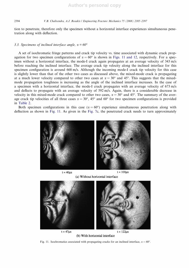
3.3. Specimens of inclined interface angle, a = 60�
A set of isochromatic fringe patterns and crack tip velocity vs. time associated with dynamic crack prop-agation for two specimen configurations of a = 60� is shown in Figs. 11 and 12, respectively. For a spec-imen without a horizontal interface, the mode-I crack again propagates at an average velocity of 343 m/sbefore reaching the inclined interface. The average crack tip velocity along the inclined interface for thisspecimen configuration is around 668 m/s. Although the incoming mode-I crack tip velocity for this caseis slightly lower than that of the other two cases as discussed above, the mixed-mode crack is propagatingat a much lower velocity compared to other two cases at a = 30� and 45�. This suggests that the mixed-mode propagation toughness is increasing as the angle of the inclined interface increases. In the case ofa specimen with a horizontal interface, the mode-I crack propagates with an average velocity of 673 m/sand deflects to propagate with an average velocity of 592 m/s. Again, there is a considerable decrease invelocity in this mixed-mode crack compared to other two cases, a = 30� and 45�. The summary of the aver-age crack tip velocities of all three cases a = 30�, 45� and 60� for two specimen configurations is providedin Table 2.
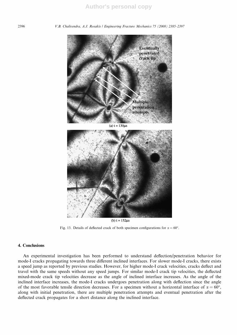
Both specimen configurations in this case (a = 60�) experience simultaneous penetration along withdeflection as shown in Fig. 11. As given in the Fig. 7c, the penetrated crack needs to turn approximately
Fig. 11. Isochromatics associated with propagating cracks for an inclined interface, a = 60�.
2394 V.B. Chalivendra, A.J. Rosakis / Engineering Fracture Mechanics 75 (2008) 2385–2397

Author's personal copy
30� to penetrate in the favorable tensile stress direction. The stress-field or energy release rate associatedwith the mode-I crack of both velocities matches well with the requirement of resistance of the favorablepenetration path, resulting in simultaneous penetration along with deflection in both cases. It is interestingto mention here that the deflected crack of the specimen without a horizontal interface undergoes multiplepenetration attempts after having travelled for some distance, as shown in Fig. 11a. The deflected crackeventually penetrates back into the Homalite-100 material. The details of the multiple penetrations andeventual penetration of the deflected crack can be seen in the blow-up picture taken at time t = 130 ls inthe Fig. 13a. However, the deflected crack of the specimen with horizontal interface undergoes no penetra-tion attempts during deflection, as shown in Fig. 13b taken at time t = 152 ls. The multiple penetrationattempts of the first case can be attributed to several reasons. One of the reasons might be that the inclinedinterface is closer to the loading points of the notch faces in this specimen configuration of a = 60�. Thecloser loading helps to choose favorable tensile paths associated with a propagating mixed-mode stress-field.It is also important to mention here that the penetration angle is no longer perpendicular to the interface.This change in penetration angle is also affected by the closeness of the inclined interface to the loadingpoints of the specimen, as well as the change in non-singular stress (T-stress) associated with the propagatingcrack.
0
100
200
300
400
500
600
700
800
0 20 40 60 80 100 120 140 160 180Time (μs)
Cra
ck ti
p ve
loci
ty
Without Horizontal interface
With Horizontal interface
Arrival times of the crack tips at the inclined interface ≈ 77 & 86μs
Fig. 12. Crack tip velocity history of a propagating crack for an inclined interface, a = 60�.
Table 2Average velocity (m/s) of crack propagation for all cases
Interface angle Horizontal interface Mode-I crack tip velocity (m/s) Mixed-mode crack tip velocity (m/s)
30� No 384 917Yes 720 714
45� No 393 841Yes 748 678
60� No 343 668Yes 673 592
V.B. Chalivendra, A.J. Rosakis / Engineering Fracture Mechanics 75 (2008) 2385–2397 2395
Author's personal copy
4. Conclusions
An experimental investigation has been performed to understand deflection/penetration behavior formode-I cracks propagating towards three different inclined interfaces. For slower mode-I cracks, there existsa speed jump as reported by previous studies. However, for higher mode-I crack velocities, cracks deflect andtravel with the same speeds without any speed jumps. For similar mode-I crack tip velocities, the deflectedmixed-mode crack tip velocities decrease as the angle of inclined interface increases. As the angle of theinclined interface increases, the mode-I cracks undergoes penetration along with deflection since the angleof the most favorable tensile direction decreases. For a specimen without a horizontal interface of a = 60�,along with initial penetration, there are multiple penetration attempts and eventual penetration after thedeflected crack propagates for a short distance along the inclined interface.
Fig. 13. Details of deflected crack of both specimen configurations for a = 60�.
2396 V.B. Chalivendra, A.J. Rosakis / Engineering Fracture Mechanics 75 (2008) 2385–2397

Author's personal copy
Acknowledgements
The authors would like to acknowledge the support of the Department of Energy through the ASCI-ASAPprogram, grant number DIM.ASC 1.1.7S LLNL.ASCP. Helpful discussions with Dr. Soonsung Hong andProf. G. Ravichandran from Caltech are also acknowledged.
References
[1] Freund LB. Dynamic fracture mechanics. New York: Cambridge University Press; 1990.[2] Broberg KB. Cracks and fracture. San Diego: Academic Press; 1999.[3] Washabaugh PG, Knauss WG. A reconciliation of dynamic crack growth velocity and Rayleigh wave speed in isotropic brittle solids.
Int J Fract 1994;65:97–114.[4] Rosakis AJ, Samudrala O, Coker D. Cracks faster than shear wave speed. Science 1999;284:1337–40.[5] Gao H, Huang Y, Gumbsch P, Rosakis AJ. On radiation-free transonicmotion of cracks and dislocations. J Mech Phys Solids
1999;47:1941–61.[6] Geubelle PH, Kubair D. Intersonic crack propagation in homogeneous media under shear-dominated loading: numerical analysis. J
Mech Phys Solids 2001;49:571–87.[7] Xu LR, Rosakis AJ. An experimental study of impact-induced failure events in homogeneous layered materials using dynamic
photoelasticity and high-speed photography. Opt Lasers Engng 2003;40:263–88.[8] Xu LR, Huang YY, Rosakis AJ. Dynamic crack deflection and penetration at interface in homogenous materials: experimental
studies and model predictions. J Mech Phys Solids 2003;51:461–86.[9] Cook J, Gordon JE. A mechanism for the control of crack propagation in all brittle systems. Proc Roy Soc 1964;282A:508–20.
[10] He MY, Hutchinson JW. Crack deflection at an interface between dissimilar elastic materials. Int J Solids Struct 1989;25:1053–67.[11] Gupta V, Argon AS, Suo Z. Crack deflection at an interface between two orthotropic materials 2001;59:s79–87.[12] Evans AG, Zok FW. Review the physics and mechanics of fiber-reinforced brittle matrix composites. J Mater Sci 1994;29:3857–96.[13] Martinez D, Gupta V. Energy criterion for crack deflection at an interface between two orthotropic media. J Mech Phys Solids
1994;42(8):1247–71.[14] Ahn BK, Curtin WA, Parthasarathy TA, Dutton RE. Criteria for crack deflection/penetration for fiber-reinforced ceramic matrix
composites. Compos Sci Technol 1998;58:1775–84.[15] Leguillon D, Lacroix C, Martin E. Interface debonding ahead of a primary crack. J Mech Phys Solids 2000;48:2137–61.[16] He MY, Hsueh CH, Becher PF. Deflection versus penetration of a wedge-loaded crack: effects of branch-crack length and penetrated-
layer width. Composites: Part B 2000;31:299–308.[17] Qin QH, Zhang X. Crack deflection at an interface between dissimilar piezoelectric materials. Int J Fract 2000;102:355–70.[18] Rosakis AJ. Intersonic shear cracks and fault ruptures. Adv Phys 2002;51(4):1189–257.[19] Cotterell B, Rice JR. Slightly curved or kinked cracks. Int J Fract 1980;16(2):155–69.[20] Dally JW. Dynamic photoelastic studies of fracture. Exp Mech 1979;19:349–61.
V.B. Chalivendra, A.J. Rosakis / Engineering Fracture Mechanics 75 (2008) 2385–2397 2397