Embed Size (px)
Citation preview
INTEL 80386 PROGRAMMER'S REFERENCE MANUAL 1986
Page 1 of 421
INTEL 80386PROGRAMMER'S REFERENCE MANUAL
1986
Intel Corporation makes no warranty for the use of its products andassumes no responsibility for any errors which may appear in this documentnor does it make a commitment to update the information contained herein.
Intel retains the right to make changes to these specifications at anytime, without notice.
Contact your local sales office to obtain the latest specifications beforeplacing your order.
The following are trademarks of Intel Corporation and may only be used toidentify Intel Products:
Above, BITBUS, COMMputer, CREDIT, Data Pipeline, FASTPATH, Genius, i, î,ICE, iCEL, iCS, iDBP, iDIS, I²ICE, iLBX, im, iMDDX, iMMX, Inboard,Insite, Intel, intel, intelBOS, Intel Certified, Intelevision,inteligent Identifier, inteligent Programming, Intellec, Intellink,iOSP, iPDS, iPSC, iRMK, iRMX, iSBC, iSBX, iSDM, iSXM, KEPROM, LibraryManager, MAPNET, MCS, Megachassis, MICROMAINFRAME, MULTIBUS, MULTICHANNEL,MULTIMODULE, MultiSERVER, ONCE, OpenNET, OTP, PC BUBBLE, Plug-A-Bubble,PROMPT, Promware, QUEST, QueX, Quick-Pulse Programming, Ripplemode, RMX/80,RUPI, Seamless, SLD, SugarCube, SupportNET, UPI, and VLSiCEL, and thecombination of ICE, iCS, iRMX, iSBC, iSBX, iSXM, MCS, or UPI and a numericalsuffix, 4-SITE.
MDS is an ordering code only and is not used as a product name ortrademark. MDS(R) is a registered trademark of Mohawk Data SciencesCorporation.
Additional copies of this manual or other Intel literature may be obtainedfrom:
Intel CorporationLiterature DistributionMail Stop SC6-593065 Bowers AvenueSanta Clara, CA 95051
INTEL CORPORATION 1987 CG-5/26/87 Edited 2001-02-01 by G.N.
INTEL 80386 PROGRAMMER'S REFERENCE MANUAL 1986
Page 2 of 421
Customer Support
───────────────────────────────────────────────────────────────────────────
Customer Support is Intel's complete support service that provides Intelcustomers with hardware support, software support, customer training, andconsulting services. For more information contact your local sales offices.
After a customer purchases any system hardware or software product,service and support become major factors in determining whether thatproduct will continue to meet a customer's expectations. Such supportrequires an international support organization and a breadth of programsto meet a variety of customer needs. As you might expect, Intel's customersupport is quite extensive. It includes factory repair services andworldwide field service offices providing hardware repair services,software support services, customer training classes, and consultingservices.
Hardware Support Services
Intel is committed to providing an international service support packagethrough a wide variety of service offerings available from Intel HardwareSupport.
Software Support Services
Intel's software support consists of two levels of contracts. Standardsupport includes TIPS (Technical Information Phone Service), updates andsubscription service (product-specific troubleshooting guides and COMMENTSMagazine). Basic support includes updates and the subscription service.Contracts are sold in environments which represent product groupings(i.e., iRMX environment).
Consulting Services
Intel provides field systems engineering services for any phase of yourdevelopment or support effort. You can use our systems engineers in avariety of ways ranging from assistance in using a new product, developingan application, personalizing training, and customizing or tailoring anIntel product to providing technical and management consulting. SystemsEngineers are well versed in technical areas such as microcommunications,real-time applications, embedded microcontrollers, and network services.You know your application needs; we know our products. Working together wecan help you get a successful product to market in the least possible time.
Customer Training
Intel offers a wide range of instructional programs covering variousaspects of system design and implementation. In just three to ten days alimited number of individuals learn more in a single workshop than inweeks of self-study. For optimum convenience, workshops are scheduledregularly at Training Centers woridwide or we can take our workshops toyou for on-site instruction. Covering a wide variety of topics, Intel'smajor course categories include: architecture and assembly language,programming and operating systems, bitbus and LAN applications.

INTEL 80386 PROGRAMMER'S REFERENCE MANUAL 1986
Page 3 of 421
Training Center Locations
To obtain a complete catalog of our workshops, call the nearest TrainingCenter in your area.
Boston (617) 692-1000Chicago (312) 310-5700San Francisco (415) 940-7800Washington D.C. (301) 474-2878Isreal (972) 349-491-099Tokyo 03-437-6611Osaka (Call Tokyo) 03-437-6611Toronto, Canada (416) 675-2105London (0793) 696-000Munich (089) 5389-1Paris (01) 687-22-21Stockholm (468) 734-01-00Milan 39-2-82-44-071Benelux (Rotterdam) (10) 21-23-77Copenhagen (1) 198-033Hong Kong 5-215311-7

INTEL 80386 PROGRAMMER'S REFERENCE MANUAL 1986
Page 4 of 421
Table of Contents
CUSTOMER SUPPORT......................................................................................................................................... 2
CHAPTER 1 INTRODUCTION TO THE 80386 .............................................................................................. 15
1.1 ORGANIZATION OF THIS MANUAL ................................................................................................................. 151.1.1 Part I ── Applications Programming ................................................................................................... 161.1.2 Part II ── Systems Programming ......................................................................................................... 171.1.3 Part III ── Compatibility ...................................................................................................................... 181.1.4 Part IV ── Instruction Set..................................................................................................................... 181.1.5 Appendices ............................................................................................................................................. 18
1.2 RELATED LITERATURE................................................................................................................................... 191.3 NOTATIONAL CONVENTIONS ......................................................................................................................... 19
1.3.1 Data-Structure Formats......................................................................................................................... 191.3.2 Undefined Bits and Software Compatibility........................................................................................... 191.3.3 Instruction Operands ............................................................................................................................. 201.3.4 Hexadecimal Numbers ........................................................................................................................... 211.3.5 Sub- and Super-Scripts........................................................................................................................... 21
CHAPTER 2 BASIC PROGRAMMING MODEL............................................................................................ 22
2.1 MEMORY ORGANIZATION AND SEGMENTATION ............................................................................................ 222.1.1 The "Flat" Model ................................................................................................................................... 232.1.2 The Segmented Model ............................................................................................................................ 23
2.2 DATA TYPES.................................................................................................................................................. 242.3 REGISTERS..................................................................................................................................................... 29
2.3.1 General Registers................................................................................................................................... 292.3.2 Segment Registers .................................................................................................................................. 302.3.3 Stack Implementation............................................................................................................................. 322.3.4 Flags Register ........................................................................................................................................ 33
2.3.4.1 Status Flags ....................................................................................................................................................... 342.3.4.2 Control Flag....................................................................................................................................................... 342.3.4.3 Instruction Pointer ............................................................................................................................................. 35
2.4 INSTRUCTION FORMAT .................................................................................................................................. 352.5 OPERAND SELECTION .................................................................................................................................... 36
2.5.1 Immediate Operands .............................................................................................................................. 372.5.2 Register Operands ................................................................................................................................. 382.5.3 Memory Operands ................................................................................................................................. 38
2.5.3.1 Segment Selection ............................................................................................................................................. 392.5.3.2 Effective-Address Computation ........................................................................................................................ 40
2.6 INTERRUPTS AND EXCEPTIONS....................................................................................................................... 42
CHAPTER 3 APPLICATIONS INSTRUCTION SET ..................................................................................... 45
3.1 DATA MOVEMENT INSTRUCTIONS ................................................................................................................. 453.1.1 General-Purpose Data Movement Instructions ..................................................................................... 453.1.2 Stack Manipulation Instructions ............................................................................................................ 463.1.3 Type Conversion Instructions ................................................................................................................ 48
3.2 BINARY ARITHMETIC INSTRUCTIONS............................................................................................................. 503.2.1 Addition and Subtraction Instructions ................................................................................................... 513.2.2 Comparison and Sign Change Instruction ............................................................................................. 513.2.3 Multiplication Instructions..................................................................................................................... 513.2.4 Division Instructions .............................................................................................................................. 52
3.3 DECIMAL ARITHMETIC INSTRUCTIONS .......................................................................................................... 533.3.1 Packed BCD Adjustment Instructions .................................................................................................... 533.3.2 Unpacked BCD Adjustment Instructions................................................................................................ 54
3.4 LOGICAL INSTRUCTIONS ................................................................................................................................ 54
INTEL 80386 PROGRAMMER'S REFERENCE MANUAL 1986
Page 5 of 421
3.4.1 Boolean Operation Instructions............................................................................................................. 543.4.2 Bit Test and Modify Instructions ............................................................................................................ 553.4.3 Bit Scan Instructions .............................................................................................................................. 553.4.4 Shift and Rotate Instructions.................................................................................................................. 56
3.4.4.1 Shift Instructions ............................................................................................................................................... 563.4.4.2 Double-Shift Instructions .................................................................................................................................. 583.4.4.3 Rotate Instructions............................................................................................................................................. 593.4.4.4 Fast "BIT BLT" Using Double Shift Instructions.............................................................................................. 613.4.4.5 Fast Bit-String Insert and Extract ...................................................................................................................... 61
3.4.5 Byte-Set-On-Condition Instructions....................................................................................................... 643.4.6 Test Instruction ...................................................................................................................................... 64
3.5 CONTROL TRANSFER INSTRUCTIONS ............................................................................................................. 653.5.1 Unconditional Transfer Instructions...................................................................................................... 65
3.5.1.1 Jump Instruction ................................................................................................................................................ 653.5.1.2 Call Instruction .................................................................................................................................................. 663.5.1.3 Return and Return-From-Interrupt Instruction .................................................................................................. 66
3.5.2 Conditional Transfer Instructions.......................................................................................................... 663.5.2.1 Conditional Jump Instructions........................................................................................................................... 673.5.2.2 Loop Instructions............................................................................................................................................... 673.5.2.3 Executing a Loop or Repeat Zero Times ........................................................................................................... 68
3.5.3 Software-Generated Interrupts .............................................................................................................. 683.6 STRING AND CHARACTER TRANSLATION INSTRUCTIONS............................................................................... 69
3.6.1 Repeat Prefixes ...................................................................................................................................... 703.6.2 Indexing and Direction Flag Control .................................................................................................... 713.6.3 String Instructions.................................................................................................................................. 71
3.7 INSTRUCTIONS FOR BLOCK-STRUCTURED LANGUAGES................................................................................. 723.8 FLAG CONTROL INSTRUCTIONS ..................................................................................................................... 79
3.8.1 Carry and Direction Flag Control Instructions ..................................................................................... 793.8.2 Flag Transfer Instructions ..................................................................................................................... 79
3.9 COPROCESSOR INTERFACE INSTRUCTIONS..................................................................................................... 803.10 SEGMENT REGISTER INSTRUCTIONS ............................................................................................................ 81
3.10.1 Segment-Register Transfer Instructions............................................................................................... 823.10.2 Far Control Transfer Instructions ....................................................................................................... 823.10.3 Data Pointer Instructions..................................................................................................................... 82
3.11 MISCELLANEOUS INSTRUCTIONS ................................................................................................................. 833.11.1 Address Calculation Instruction .......................................................................................................... 833.11.2 No-Operation Instruction..................................................................................................................... 843.11.3 Translate Instruction............................................................................................................................ 84
CHAPTER 4 SYSTEMS ARCHITECTURE..................................................................................................... 85
4.1 SYSTEMS REGISTERS ..................................................................................................................................... 854.1.1 Systems Flags......................................................................................................................................... 854.1.2 Memory-Management Registers ............................................................................................................ 874.1.3 Control Registers ................................................................................................................................... 874.1.4 Debug Register....................................................................................................................................... 884.1.5 Test Registers ......................................................................................................................................... 89
4.2 SYSTEMS INSTRUCTIONS................................................................................................................................ 89
CHAPTER 5 MEMORY MANAGEMENT....................................................................................................... 91
5.1 SEGMENT TRANSLATION ............................................................................................................................... 925.1.1 Descriptors............................................................................................................................................. 925.1.2 Descriptor Tables................................................................................................................................... 945.1.3 Selectors................................................................................................................................................. 965.1.4 Segment Registers .................................................................................................................................. 97
5.2 PAGE TRANSLATION ...................................................................................................................................... 985.2.1 Page Frame............................................................................................................................................ 985.2.2 Linear Address ....................................................................................................................................... 98
INTEL 80386 PROGRAMMER'S REFERENCE MANUAL 1986
Page 6 of 421
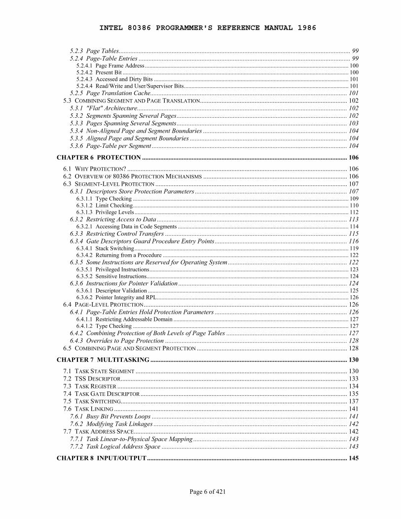
5.2.3 Page Tables............................................................................................................................................ 995.2.4 Page-Table Entries ................................................................................................................................ 99
5.2.4.1 Page Frame Address ........................................................................................................................................ 1005.2.4.2 Present Bit ....................................................................................................................................................... 1005.2.4.3 Accessed and Dirty Bits .................................................................................................................................. 1015.2.4.4 Read/Write and User/Supervisor Bits.............................................................................................................. 101
5.2.5 Page Translation Cache....................................................................................................................... 1015.3 COMBINING SEGMENT AND PAGE TRANSLATION......................................................................................... 102
5.3.1 "Flat" Architecture............................................................................................................................... 1025.3.2 Segments Spanning Several Pages....................................................................................................... 1025.3.3 Pages Spanning Several Segments....................................................................................................... 1035.3.4 Non-Aligned Page and Segment Boundaries ....................................................................................... 1045.3.5 Aligned Page and Segment Boundaries ............................................................................................... 1045.3.6 Page-Table per Segment ...................................................................................................................... 104
CHAPTER 6 PROTECTION ............................................................................................................................ 106
6.1 WHY PROTECTION? ..................................................................................................................................... 1066.2 OVERVIEW OF 80386 PROTECTION MECHANISMS ....................................................................................... 1066.3 SEGMENT-LEVEL PROTECTION .................................................................................................................... 107
6.3.1 Descriptors Store Protection Parameters ............................................................................................ 1076.3.1.1 Type Checking ................................................................................................................................................ 1096.3.1.2 Limit Checking................................................................................................................................................ 1106.3.1.3 Privilege Levels ............................................................................................................................................... 112
6.3.2 Restricting Access to Data ................................................................................................................... 1136.3.2.1 Accessing Data in Code Segments .................................................................................................................. 114
6.3.3 Restricting Control Transfers .............................................................................................................. 1156.3.4 Gate Descriptors Guard Procedure Entry Points................................................................................ 116
6.3.4.1 Stack Switching............................................................................................................................................... 1196.3.4.2 Returning from a Procedure ............................................................................................................................ 122
6.3.5 Some Instructions are Reserved for Operating System ........................................................................ 1226.3.5.1 Privileged Instructions..................................................................................................................................... 1236.3.5.2 Sensitive Instructions....................................................................................................................................... 124
6.3.6 Instructions for Pointer Validation ...................................................................................................... 1246.3.6.1 Descriptor Validation ...................................................................................................................................... 1256.3.6.2 Pointer Integrity and RPL................................................................................................................................ 126
6.4 PAGE-LEVEL PROTECTION........................................................................................................................... 1266.4.1 Page-Table Entries Hold Protection Parameters ................................................................................ 126
6.4.1.1 Restricting Addressable Domain ..................................................................................................................... 1276.4.1.2 Type Checking ................................................................................................................................................ 127
6.4.2 Combining Protection of Both Levels of Page Tables ......................................................................... 1276.4.3 Overrides to Page Protection .............................................................................................................. 128
6.5 COMBINING PAGE AND SEGMENT PROTECTION ........................................................................................... 128
CHAPTER 7 MULTITASKING ....................................................................................................................... 130
7.1 TASK STATE SEGMENT ................................................................................................................................ 1307.2 TSS DESCRIPTOR......................................................................................................................................... 1337.3 TASK REGISTER ........................................................................................................................................... 1347.4 TASK GATE DESCRIPTOR ............................................................................................................................. 1357.5 TASK SWITCHING......................................................................................................................................... 1377.6 TASK LINKING ............................................................................................................................................. 141
7.6.1 Busy Bit Prevents Loops ...................................................................................................................... 1417.6.2 Modifying Task Linkages ..................................................................................................................... 142
7.7 TASK ADDRESS SPACE................................................................................................................................. 1427.7.1 Task Linear-to-Physical Space Mapping ............................................................................................. 1437.7.2 Task Logical Address Space ................................................................................................................ 143
CHAPTER 8 INPUT/OUTPUT......................................................................................................................... 145

INTEL 80386 PROGRAMMER'S REFERENCE MANUAL 1986
Page 7 of 421
8.1 I/O ADDRESSING ......................................................................................................................................... 1458.1.1 I/O Address Space................................................................................................................................ 1458.1.2 Memory-Mapped I/O............................................................................................................................ 146
8.2 I/O INSTRUCTIONS....................................................................................................................................... 1468.2.1 Register I/O Instructions...................................................................................................................... 1468.2.2 Block I/O Instructions .......................................................................................................................... 147
8.3 PROTECTION AND I/O .................................................................................................................................. 1488.3.1 I/O Privilege Level ............................................................................................................................... 1498.3.2 I/O Permission Bit Map ....................................................................................................................... 149
CHAPTER 9 EXCEPTIONS AND INTERRUPTS......................................................................................... 152
9.1 IDENTIFYING INTERRUPTS............................................................................................................................ 1529.2 ENABLING AND DISABLING INTERRUPTS ..................................................................................................... 153
9.2.1 NMI Masks Further NMIs.................................................................................................................... 1549.2.2 IF Masks INTR..................................................................................................................................... 1549.2.3 RF Masks Debug Faults....................................................................................................................... 1549.2.4 MOV or POP to SS Masks Some Interrupts and Exceptions................................................................ 154
9.3 PRIORITY AMONG SIMULTANEOUS INTERRUPTS AND EXCEPTIONS ............................................................. 1559.4 INTERRUPT DESCRIPTOR TABLE .................................................................................................................. 1559.5 IDT DESCRIPTORS ....................................................................................................................................... 1579.6 INTERRUPT TASKS AND INTERRUPT PROCEDURES ....................................................................................... 157
9.6.1 Interrupt Procedures............................................................................................................................ 1589.6.1.1 Stack of Interrupt Procedure............................................................................................................................ 1589.6.1.2 Returning from an Interrupt Procedure............................................................................................................ 1599.6.1.3 Flags Usage by Interrupt Procedure ................................................................................................................ 1609.6.1.4 Protection in Interrupt Procedures ................................................................................................................... 160
9.6.2 Interrupt Tasks ..................................................................................................................................... 1609.7 ERROR CODE ............................................................................................................................................... 1619.8 EXCEPTION CONDITIONS.............................................................................................................................. 162
9.8.1 Interrupt 0 ── Divide Error................................................................................................................ 1629.8.2 Interrupt 1 ── Debug Exceptions ....................................................................................................... 1639.8.3 Interrupt 3 ── Breakpoint................................................................................................................... 1639.8.4 Interrupt 4 ── Overflow...................................................................................................................... 1639.8.5 Interrupt 5 ── Bounds Check.............................................................................................................. 1639.8.6 Interrupt 6 ── Invalid Opcode............................................................................................................ 1649.8.7 Interrupt 7 ── Coprocessor Not Available ......................................................................................... 1649.8.8 Interrupt 8 ── Double Fault ............................................................................................................... 1649.8.9 Interrupt 9 ── Coprocessor Segment Overrun ................................................................................... 1659.8.10 Interrupt 10 ── Invalid TSS .............................................................................................................. 1659.8.11 Interrupt 11 ── Segment Not Present ............................................................................................... 1669.8.12 Interrupt 12 ── Stack Exception ....................................................................................................... 1679.8.13 Interrupt 13 ── General Protection Exception................................................................................. 1689.8.14 Interrupt 14 ── Page Fault............................................................................................................... 169
9.8.14.1 Page Fault During Task Switch ..................................................................................................................... 1709.8.14.2 Page Fault with Inconsistent Stack Pointer.................................................................................................... 171
9.8.15 Interrupt 16 ── Coprocessor Error .................................................................................................. 1719.9 EXCEPTION SUMMARY................................................................................................................................. 1729.10 ERROR CODE SUMMARY............................................................................................................................ 173
CHAPTER 10 INITIALIZATION .................................................................................................................... 174
10.1 PROCESSOR STATE AFTER RESET .............................................................................................................. 17410.2 SOFTWARE INITIALIZATION FOR REAL-ADDRESS MODE ........................................................................... 175
10.2.1 Stack................................................................................................................................................... 17510.2.2 Interrupt Table ................................................................................................................................... 17510.2.3 First Instructions................................................................................................................................ 176
10.3 SWITCHING TO PROTECTED MODE............................................................................................................. 176
INTEL 80386 PROGRAMMER'S REFERENCE MANUAL 1986
Page 8 of 421
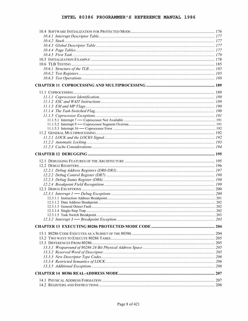
10.4 SOFTWARE INITIALIZATION FOR PROTECTED MODE.................................................................................. 17610.4.1 Interrupt Descriptor Table................................................................................................................. 17710.4.2 Stack................................................................................................................................................... 17710.4.3 Global Descriptor Table .................................................................................................................... 17710.4.4 Page Tables........................................................................................................................................ 17710.4.5 First Task ........................................................................................................................................... 178
10.5 INITIALIZATION EXAMPLE ......................................................................................................................... 17810.6 TLB TESTING ............................................................................................................................................ 185
10.6.1 Structure of the TLB........................................................................................................................... 18510.6.2 Test Registers ..................................................................................................................................... 18510.6.3 Test Operations.................................................................................................................................. 188
CHAPTER 11 COPROCESSING AND MULTIPROCESSING ................................................................... 189
11.1 COPROCESSING .......................................................................................................................................... 18911.1.1 Coprocessor Identification................................................................................................................. 18911.1.2 ESC and WAIT Instructions ............................................................................................................... 18911.1.3 EM and MP Flags.............................................................................................................................. 19011.1.4 The Task-Switched Flag..................................................................................................................... 19011.1.5 Coprocessor Exceptions..................................................................................................................... 191
11.1.5.1 Interrupt 7 ── Coprocessor Not Available ................................................................................................... 19111.1.5.2 Interrupt 9 ── Coprocessor Segment Overrun.............................................................................................. 19111.1.5.3 Interrupt 16 ── Coprocessor Error ............................................................................................................... 192
11.2 GENERAL MULTIPROCESSING .................................................................................................................... 19211.2.1 LOCK and the LOCK# Signal............................................................................................................ 19211.2.2 Automatic Locking ............................................................................................................................. 19311.2.3 Cache Considerations ........................................................................................................................ 194
CHAPTER 12 DEBUGGING ............................................................................................................................ 195
12.1 DEBUGGING FEATURES OF THE ARCHITECTURE ........................................................................................ 19512.2 DEBUG REGISTERS..................................................................................................................................... 196
12.2.1 Debug Address Registers (DR0-DR3)................................................................................................ 19712.2.2 Debug Control Register (DR7) .......................................................................................................... 19812.2.3 Debug Status Register (DR6) ............................................................................................................. 19812.2.4 Breakpoint Field Recognition ............................................................................................................ 199
12.3 DEBUG EXCEPTIONS .................................................................................................................................. 20012.3.1 Interrupt 1 ── Debug Exceptions ..................................................................................................... 200
12.3.1.1 Instruction Addrees Breakpoint..................................................................................................................... 20112.3.1.2 Data Address Breakpoint............................................................................................................................... 20212.3.1.3 General Detect Fault...................................................................................................................................... 20212.3.1.4 Single-Step Trap............................................................................................................................................ 20212.3.1.5 Task Switch Breakpoint ................................................................................................................................ 203
12.3.2 Interrupt 3 ── Breakpoint Exception................................................................................................ 203
CHAPTER 13 EXECUTING 80286 PROTECTED-MODE CODE .............................................................. 204
13.1 80286 CODE EXECUTES AS A SUBSET OF THE 80386 ................................................................................. 20413.2 TWO WAYS TO EXECUTE 80286 TASKS...................................................................................................... 20513.3 DIFFERENCES FROM 80286........................................................................................................................ 205
13.3.1 Wraparound of 80286 24-Bit Physical Address Space ...................................................................... 20513.3.2 Reserved Word of Descriptor............................................................................................................. 20513.3.3 New Descriptor Type Codes............................................................................................................... 20613.3.4 Restricted Semantics of LOCK........................................................................................................... 20613.3.5 Additional Exceptions ........................................................................................................................ 206
CHAPTER 14 80386 REAL-ADDRESS MODE.............................................................................................. 207
14.1 PHYSICAL ADDRESS FORMATION .............................................................................................................. 20714.2 REGISTERS AND INSTRUCTIONS ................................................................................................................. 208
INTEL 80386 PROGRAMMER'S REFERENCE MANUAL 1986
Page 9 of 421
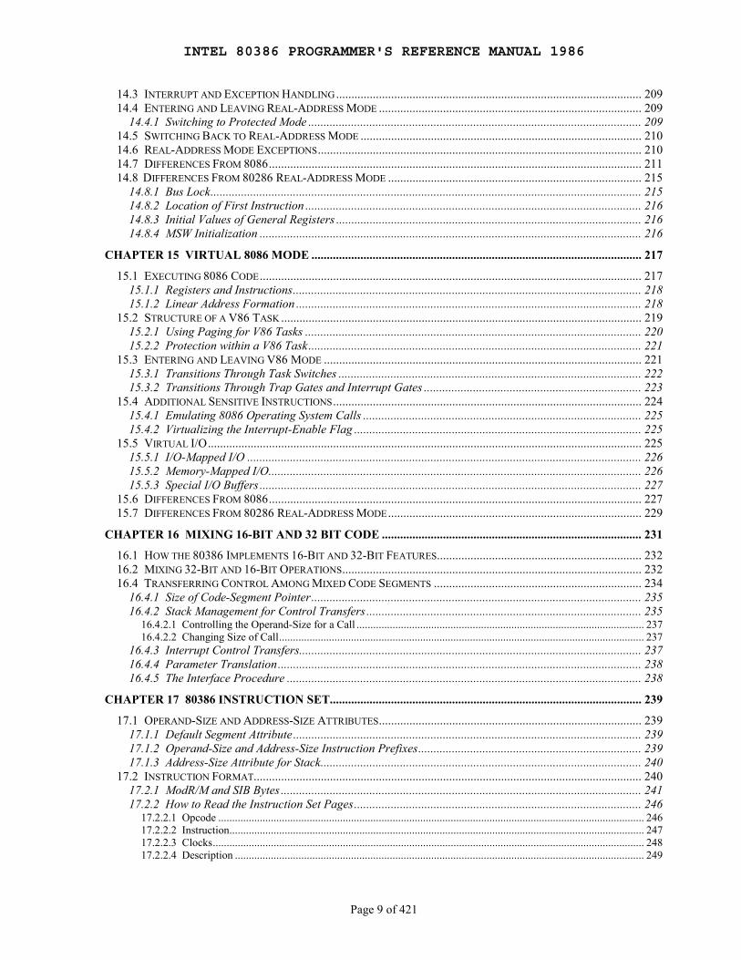
14.3 INTERRUPT AND EXCEPTION HANDLING.................................................................................................... 20914.4 ENTERING AND LEAVING REAL-ADDRESS MODE ...................................................................................... 209
14.4.1 Switching to Protected Mode ............................................................................................................. 20914.5 SWITCHING BACK TO REAL-ADDRESS MODE ............................................................................................ 21014.6 REAL-ADDRESS MODE EXCEPTIONS.......................................................................................................... 21014.7 DIFFERENCES FROM 8086.......................................................................................................................... 21114.8 DIFFERENCES FROM 80286 REAL-ADDRESS MODE ................................................................................... 215
14.8.1 Bus Lock............................................................................................................................................. 21514.8.2 Location of First Instruction .............................................................................................................. 21614.8.3 Initial Values of General Registers .................................................................................................... 21614.8.4 MSW Initialization ............................................................................................................................. 216
CHAPTER 15 VIRTUAL 8086 MODE ............................................................................................................ 217
15.1 EXECUTING 8086 CODE............................................................................................................................. 21715.1.1 Registers and Instructions.................................................................................................................. 21815.1.2 Linear Address Formation ................................................................................................................. 218
15.2 STRUCTURE OF A V86 TASK ...................................................................................................................... 21915.2.1 Using Paging for V86 Tasks .............................................................................................................. 22015.2.2 Protection within a V86 Task............................................................................................................. 221
15.3 ENTERING AND LEAVING V86 MODE ........................................................................................................ 22115.3.1 Transitions Through Task Switches ................................................................................................... 22215.3.2 Transitions Through Trap Gates and Interrupt Gates ....................................................................... 223
15.4 ADDITIONAL SENSITIVE INSTRUCTIONS..................................................................................................... 22415.4.1 Emulating 8086 Operating System Calls ........................................................................................... 22515.4.2 Virtualizing the Interrupt-Enable Flag .............................................................................................. 225
15.5 VIRTUAL I/O.............................................................................................................................................. 22515.5.1 I/O-Mapped I/O ................................................................................................................................. 22615.5.2 Memory-Mapped I/O.......................................................................................................................... 22615.5.3 Special I/O Buffers ............................................................................................................................. 227
15.6 DIFFERENCES FROM 8086.......................................................................................................................... 22715.7 DIFFERENCES FROM 80286 REAL-ADDRESS MODE................................................................................... 229
CHAPTER 16 MIXING 16-BIT AND 32 BIT CODE ..................................................................................... 231
16.1 HOW THE 80386 IMPLEMENTS 16-BIT AND 32-BIT FEATURES................................................................... 23216.2 MIXING 32-BIT AND 16-BIT OPERATIONS.................................................................................................. 23216.4 TRANSFERRING CONTROL AMONG MIXED CODE SEGMENTS .................................................................... 234
16.4.1 Size of Code-Segment Pointer............................................................................................................ 23516.4.2 Stack Management for Control Transfers .......................................................................................... 235
16.4.2.1 Controlling the Operand-Size for a Call ........................................................................................................ 23716.4.2.2 Changing Size of Call.................................................................................................................................... 237
16.4.3 Interrupt Control Transfers................................................................................................................ 23716.4.4 Parameter Translation....................................................................................................................... 23816.4.5 The Interface Procedure .................................................................................................................... 238
CHAPTER 17 80386 INSTRUCTION SET...................................................................................................... 239
17.1 OPERAND-SIZE AND ADDRESS-SIZE ATTRIBUTES...................................................................................... 23917.1.1 Default Segment Attribute .................................................................................................................. 23917.1.2 Operand-Size and Address-Size Instruction Prefixes......................................................................... 23917.1.3 Address-Size Attribute for Stack......................................................................................................... 240
17.2 INSTRUCTION FORMAT............................................................................................................................... 24017.2.1 ModR/M and SIB Bytes ...................................................................................................................... 24117.2.2 How to Read the Instruction Set Pages.............................................................................................. 246
17.2.2.1 Opcode .......................................................................................................................................................... 24617.2.2.2 Instruction...................................................................................................................................................... 24717.2.2.3 Clocks............................................................................................................................................................ 24817.2.2.4 Description .................................................................................................................................................... 249
INTEL 80386 PROGRAMMER'S REFERENCE MANUAL 1986
Page 10 of 421
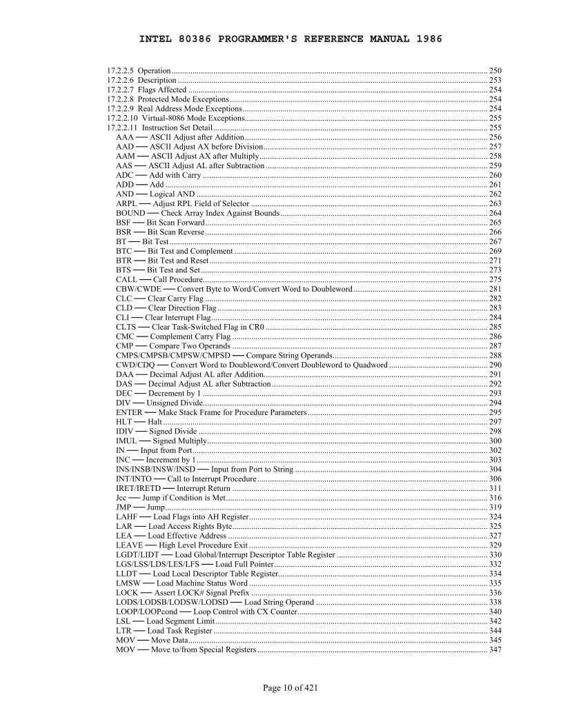
17.2.2.5 Operation....................................................................................................................................................... 25017.2.2.6 Description .................................................................................................................................................... 25317.2.2.7 Flags Affected ............................................................................................................................................... 25417.2.2.8 Protected Mode Exceptions ........................................................................................................................... 25417.2.2.9 Real Address Mode Exceptions..................................................................................................................... 25417.2.2.10 Virtual-8086 Mode Exceptions.................................................................................................................... 25517.2.2.11 Instruction Set Detail ................................................................................................................................... 255
AAA ── ASCII Adjust after Addition.................................................................................................................... 256AAD ── ASCII Adjust AX before Division........................................................................................................... 257AAM ── ASCII Adjust AX after Multiply............................................................................................................. 258AAS ── ASCII Adjust AL after Subtraction .......................................................................................................... 259ADC ── Add with Carry ........................................................................................................................................ 260ADD ── Add .......................................................................................................................................................... 261AND ── Logical AND ........................................................................................................................................... 262ARPL ── Adjust RPL Field of Selector ................................................................................................................. 263BOUND ── Check Array Index Against Bounds................................................................................................... 264BSF ── Bit Scan Forward....................................................................................................................................... 265BSR ── Bit Scan Reverse....................................................................................................................................... 266BT ── Bit Test ........................................................................................................................................................ 267BTC ── Bit Test and Complement ......................................................................................................................... 269BTR ── Bit Test and Reset..................................................................................................................................... 271BTS ── Bit Test and Set ......................................................................................................................................... 273CALL ── Call Procedure........................................................................................................................................ 275CBW/CWDE ── Convert Byte to Word/Convert Word to Doubleword ................................................................ 281CLC ── Clear Carry Flag ....................................................................................................................................... 282CLD ── Clear Direction Flag ................................................................................................................................. 283CLI ── Clear Interrupt Flag.................................................................................................................................... 284CLTS ── Clear Task-Switched Flag in CR0 .......................................................................................................... 285CMC ── Complement Carry Flag .......................................................................................................................... 286CMP ── Compare Two Operands .......................................................................................................................... 287CMPS/CMPSB/CMPSW/CMPSD ── Compare String Operands.......................................................................... 288CWD/CDQ ── Convert Word to Doubleword/Convert Doubleword to Quadword ............................................... 290DAA ── Decimal Adjust AL after Addition........................................................................................................... 291DAS ── Decimal Adjust AL after Subtraction ....................................................................................................... 292DEC ── Decrement by 1 ........................................................................................................................................ 293DIV ── Unsigned Divide........................................................................................................................................ 294ENTER ── Make Stack Frame for Procedure Parameters ...................................................................................... 295HLT ── Halt ........................................................................................................................................................... 297IDIV ── Signed Divide .......................................................................................................................................... 298IMUL ── Signed Multiply...................................................................................................................................... 300IN ── Input from Port............................................................................................................................................. 302INC ── Increment by 1........................................................................................................................................... 303INS/INSB/INSW/INSD ── Input from Port to String ............................................................................................ 304INT/INTO ── Call to Interrupt Procedure .............................................................................................................. 306IRET/IRETD ── Interrupt Return .......................................................................................................................... 311Jcc ── Jump if Condition is Met............................................................................................................................. 316JMP ── Jump.......................................................................................................................................................... 319LAHF ── Load Flags into AH Register.................................................................................................................. 324LAR ── Load Access Rights Byte.......................................................................................................................... 325LEA ── Load Effective Address ............................................................................................................................ 327LEAVE ── High Level Procedure Exit .................................................................................................................. 329LGDT/LIDT ── Load Global/Interrupt Descriptor Table Register ........................................................................ 330LGS/LSS/LDS/LES/LFS ── Load Full Pointer...................................................................................................... 332LLDT ── Load Local Descriptor Table Register.................................................................................................... 334LMSW ── Load Machine Status Word .................................................................................................................. 335LOCK ── Assert LOCK# Signal Prefix ................................................................................................................. 336LODS/LODSB/LODSW/LODSD ── Load String Operand .................................................................................. 338LOOP/LOOPcond ── Loop Control with CX Counter........................................................................................... 340LSL ── Load Segment Limit .................................................................................................................................. 342LTR ── Load Task Register ................................................................................................................................... 344MOV ── Move Data............................................................................................................................................... 345MOV ── Move to/from Special Registers .............................................................................................................. 347
INTEL 80386 PROGRAMMER'S REFERENCE MANUAL 1986
Page 11 of 421
MOVS/MOVSB/MOVSW/MOVSD ── Move Data from String to String............................................................ 348MOVSX ── Move with Sign-Extend ..................................................................................................................... 350MOVZX ── Move with Zero-Extend..................................................................................................................... 351MUL ── Unsigned Multiplication of AL or AX..................................................................................................... 352NEG ── Two's Complement Negation ................................................................................................................... 354NOP ── No Operation ............................................................................................................................................ 355NOT ── One's Complement Negation.................................................................................................................... 356OR ── Logical Inclusive OR .................................................................................................................................. 357OUT ── Output to Port........................................................................................................................................... 358OUTS/OUTSB/OUTSW/OUTSD ── Output String to Port................................................................................... 359POP ── Pop a Word from the Stack ....................................................................................................................... 361POPA/POPAD ── Pop all General Registers ......................................................................................................... 364POPF/POPFD ── Pop Stack into FLAGS or EFLAGS Register ............................................................................ 366PUSH ── Push Operand onto the Stack.................................................................................................................. 367PUSHA/PUSHAD ── Push all General Registers .................................................................................................. 369PUSHF/PUSHFD ── Push Flags Register onto the Stack ...................................................................................... 371RCL/RCR/ROL/ROR ── Rotate ............................................................................................................................ 372REP/REPE/REPZ/REPNE/REPNZ ── Repeat Following String Operation .......................................................... 375RET ── Return from Procedure.............................................................................................................................. 378SAHF ── Store AH into Flags................................................................................................................................ 382SAL/SAR/SHL/SHR ── Shift Instructions............................................................................................................. 383SBB ── Integer Subtraction with Borrow............................................................................................................... 386SCAS/SCASB/SCASW/SCASD ── Compare String Data .................................................................................... 387SETcc ── Byte Set on Condition............................................................................................................................ 389SGDT/SIDT ── Store Global/Interrupt Descriptor Table Register......................................................................... 391SHLD ── Double Precision Shift Left.................................................................................................................... 392SHRD ── Double Precision Shift Right ................................................................................................................. 394SLDT ── Store Local Descriptor Table Register.................................................................................................... 396SMSW ── Store Machine Status Word .................................................................................................................. 397STC ── Set Carry Flag ........................................................................................................................................... 398STD ── Set Direction Flag ..................................................................................................................................... 399STI ── Set Interrupt Flag........................................................................................................................................ 400STOS/STOSB/STOSW/STOSD ── Store String Data ........................................................................................... 401STR ── Store Task Register ................................................................................................................................... 403SUB ── Integer Subtraction ................................................................................................................................... 404TEST ── Logical Compare..................................................................................................................................... 405VERR, VERW ── Verify a Segment for Reading or Writing ................................................................................ 406WAIT ── Wait until BUSY# Pin is Inactive (HIGH)............................................................................................. 408XCHG ── Exchange Register/Memory with Register............................................................................................ 409XLAT/XLATB ── Table Look-up Translation ...................................................................................................... 410XOR ── Logical Exclusive OR .............................................................................................................................. 411
APPENDIX A OPCODE MAP.......................................................................................................................... 412
APPENDIX B COMPLETE FLAG CROSS-REFERENCE .......................................................................... 417
APPENDIX C STATUS FLAG SUMMARY ................................................................................................... 419
APPENDIX D CONDITION CODES............................................................................................................... 421
INTEL 80386 PROGRAMMER'S REFERENCE MANUAL 1986
Page 12 of 421
Figures
1-1 Example Data Structure
2-1 Two-Component Pointer2-2 Fundamental Data Types2-3 Bytes, Words, and Doublewords in Memory2-4 80386 Data Types2-5 80386 Applications Register Set2-6 Use of Memory Segmentation2-7 80386 Stack2-8 EFLAGS Register2-9 Instruction Pointer Register2-10 Effective Address Computation
3-1 PUSH3-2 PUSHA3-3 POP3-4 POPA3-5 Sign Extension3-6 SAL and SHL3-7 SHR3-8 SAR3-9 Using SAR to Simulate IDIV3-10 Shift Left Double3-11 Shift Right Double3-12 ROL3-13 ROR3-14 RCL3-15 RCR3-16 Formal Definition of the ENTER Instruction3-17 Variable Access in Nested Procedures3-18 Stack Frame for MAIN at Level 13-19 Stack Frame for Prooedure A3-20 Stack Frame for Procedure B at Level 3 Called from A3-21 Stack Frame for Procedure C at Level 3 Called from B3-22 LAHF and SAHF3-23 Flag Format for PUSHF and POPF
4-1 Systems Flags of EFLAGS Register4-2 Control Registers
5-1 Address Translation Overview5-2 Segment Translation5-3 General Segment-Descriptor Format5-4 Format of Not-Present Descriptor5-5 Descriptor Tables5-6 Format of a Selector5-7 Segment Registers5-8 Format of a Linear Address5-9 Page Translation5-10 Format of a Page Table Entry5-11 Invalid Page Table Entry5-12 80386 Addressing Mechanism5-13 Descriptor per Page Table
INTEL 80386 PROGRAMMER'S REFERENCE MANUAL 1986
Page 13 of 421
6-1 Protection Fields of Segment Descriptors6-2 Levels of Privilege6-3 Privilege Check for Data Access6-4 Privilege Check for Control Transfer without Gate6-5 Format of 80386 Call Gate6-6 Indirect Transfer via Call Gate6-7 Privilege Check via Call Gate6-8 Initial Stack Pointers of TSS6-9 Stack Contents after an Interievel Call6-10 Protection Fields of Page Table Entries
7-1 80386 32-Bit Task State Segment7-2 TSS Descriptor for 32-Bit TSS7-3 Task Register7-4 Task Gate Descriptor7-5 Task Gate Indirectly Identifies Task7-6 Partially-Overlapping Linear Spaces
8-1 Memory-Mapped I/O8-2 I/O Address Bit Map
9-1 IDT Register and Table9-2 Pseudo-Descriptor Format for LIDT and SIDT9-3 80386 IDT Gate Descriptors9-4 Interrupt Vectoring for Procedures9-5 Stack Layout after Exception of Interrupt9-6 Interrupt Vectoring for Tasks9-7 Error Code Format9-8 Page-Fault Error Code Format9-9 CR2 Format
10-1 Contents of EDX after RESET10-2 Initial Contents of CRO10-3 TLB Structure10-4 Test Registers
12-1 Debug Registers
14-1 Real-Address Mode Address Formation
15-1 V86 Mode Address Formation15-2 Entering and Leaving an 8086 Program15-3 PL 0 Stack after Interrupt in V86 Task
16-1 Stack after Far 16-Bit and 32-Bit Calls
17-1 80386 Instruction Format17-2 ModR/M and SIB Byte Formats17-3 Bit Offset for BIT[EAX, 21]17-4 Memory Bit Indexing
INTEL 80386 PROGRAMMER'S REFERENCE MANUAL 1986
Page 14 of 421
Tables
2-1 Default Segment Register Selection Rules2-2 80386 Reserved Exceptions and Interrupts
3-1 Bit Test and Modify Instructions3-2 Interpretation of Conditional Transfers
6-1 System and Gate Descriptor Types6-2 Useful Combinations of E, G, and B Bits6-3 Interievel Return Checks6-4 Valid Descriptor Types for LSL6-5 Combining Directory and Page Protection
7-1 Checks Made during a Task Switch7-2 Effect of Task Switch on BUSY, NT, and Back-Link
9-1 Interrupt and Exception ID Assignments9-2 Priority Among Simultaneous Interrupts and Exceptions9-3 Double-Fault Detection Classes9-4 Double-Fault Definition9-5 Conditions That Invalidate the TSS9-6 Exception Summary9-7 Error-Code Summary
10-1 Meaning of D, U, and W Bit Pairs
12-1 Breakpeint Field Recognition Examples12-2 Debug Exception Conditions
14-1 80386 Real-Address Mode Exceptions14-2 New 80386 Exceptions
17-1 Effective Size Attributes17-2 16-Bit Addressing Forms with the ModR/M Byte17-3 32-Bit Addressing Forms with the ModR/M Byte17-4 32-Bit Addressing Forms with the SIB Byte17-5 Task Switch Times for Exceptions17-6 80386 Exceptions
INTEL 80386 PROGRAMMER'S REFERENCE MANUAL 1986
Page 15 of 421
Chapter 1 Introduction to the 80386
────────────────────────────────────────────────────────────────────────────
The 80386 is an advanced 32-bit microprocessor optimized for multitaskingoperating systems and designed for applications needing very highperformance. The 32-bit registers and data paths support 32-bit addressesand data types. The processor can address up to four gigabytes of physicalmemory and 64 terabytes (246 bytes) of virtual memory. The on-chipmemory-management facilities include address translation registers,advanced multitasking hardware, a protection mechanism, and paged virtualmemory. Special debugging registers provide data and code breakpoints evenin ROM-based software.
1.1 Organization of This Manual
This book presents the architecture of the 80386 in five parts:
Part I ── Applications Programming Part II ── Systems Programming Part III ── Compatibility Part IV ── Instruction Set Appendices
These divisions are determined in part by the architecture itself and inpart by the different ways the book will be used. As the following tableindicates, the latter two parts are intended as reference material forprogrammers actually engaged in the process of developing software for the80386. The first three parts are explanatory, showing the purpose ofarchitectural features, developing terminology and concepts, and describinginstructions as they relate to specific purposes or to specificarchitectural features.
Explanation Part I ── Applications Programming Part II ── Systems Programming Part III ── Compatibility
Reference Part IV ── Instruction Set Appendices
The first three parts follow the execution modes and protection features ofthe 80386 CPU. The distinction between applications features and systemsfeatures is determined by the protection mechanism of the 80386. One purposeof protection is to prevent applications from interfering with the operatingsystem; therefore, the processor makes certain registers and instructionsinaccessible to applications programs. The features discussed in Part I arethose that are accessible to applications; the features in Part II areavailable only to systems software that has been given special privileges orin unprotected systems.
The processing mode of the 80386 also determines the features that areaccessible. The 80386 has three processing modes:
INTEL 80386 PROGRAMMER'S REFERENCE MANUAL 1986
Page 16 of 421
1. Protected Mode. 2. Real-Address Mode. 3. Virtual 8086 Mode.
Protected mode is the natural 32-bit environment of the 80386 processor. Inthis mode all instructions and features are available.
Real-address mode (often called just "real mode") is the mode of theprocessor immediately after RESET. In real mode the 80386 appears toprogrammers as a fast 8086 with some new instructions. Most applications ofthe 80386 will use real mode for initialization only.
Virtual 8086 mode (also called V86 mode) is a dynamic mode in the sensethat the processor can switch repeatedly and rapidly between V86 mode andprotected mode. The CPU enters V86 mode from protected mode to execute an8086 program, then leaves V86 mode and enters protected mode to continueexecuting a native 80386 program.
The features that are available to applications programs in protected modeand to all programs in V86 mode are the same. These features form thecontent of Part I. The additional features that are available to systemssoftware in protected mode form Part II. Part III explains real-addressmode and V86 mode, as well as how to execute a mix of 32-bit and 16-bitprograms.
Available in All Modes Part I ── Applications Programming
Available in Protected Part II ── Systems ProgrammingMode Only
Compatibility Modes Part III ── Compatibility
1.1.1 Part I ── Applications ProgrammingThis part presents those aspects of the architecture that are customarilyused by applications programmers.
Chapter 2 ── Basic Programming Model: Introduces the models of memoryorganization. Defines the data types. Presents the register set used byapplications. Introduces the stack. Explains string operations. Defines theparts of an instruction. Explains addressing calculations. Introducesinterrupts and exceptions as they may apply to applications programming.
Chapter 3 ── Application Instruction Set: Surveys the instructions commonlyused for applications programming. Considers instructions in functionallyrelated groups; for example, string instructions are considered in onesection, while control-transfer instructions are considered in another.Explains the concepts behind the instructions. Details of individualinstructions are deferred until Part IV, the instruction-set reference.
INTEL 80386 PROGRAMMER'S REFERENCE MANUAL 1986
Page 17 of 421
1.1.2 Part II ── Systems ProgrammingThis part presents those aspects of the architecture that are customarilyused by programmers who write operating systems, device drivers, debuggers,and other software that supports applications programs in the protected modeof the 80386.
Chapter 4 ── Systems Architecture: Surveys the features of the 80386 thatare used by systems programmers. Introduces the remaining registers and datastructures of the 80386 that were not discussed in Part I. Introduces thesystems-oriented instructions in the context of the registers and datastructures they support. Points to the chapter where each register, datastructure, and instruction is considered in more detail.
Chapter 5 ── Memory Management: Presents details of the data structures,registers, and instructions that support virtual memory and the concepts ofsegmentation and paging. Explains how systems designers can choose a modelof memory organization ranging from completely linear ("flat") to fullypaged and segmented.
Chapter 6 ── Protection: Expands on the memory management features of the80386 to include protection as it applies to both segments and pages.Explains the implementation of privilege rules, stack switching, pointervalidation, user and supervisor modes. Protection aspects of multitaskingare deferred until the following chapter.
Chapter 7 ── Multitasking: Explains how the hardware of the 80386 supportsmultitasking with context-switching operations and intertask protection.
Chapter 8 ── Input/Output: Reveals the I/O features of the 80386, includingI/O instructions, protection as it relates to I/O, and the I/O permissionmap.
Chapter 9 ── Exceptions and Interrupts: Explains the basic interruptmechanisms of the 80386. Shows how interrupts and exceptions relate toprotection. Discusses all possible exceptions, listing causes and includinginformation needed to handle and recover from the exception.
Chapter 10 ── Initialization: Defines the condition of the processor afterRESET or power-up. Explains how to set up registers, flags, and datastructures for either real-address mode or protected mode. Contains anexample of an initialization program.
Chapter 11 ── Coprocessing and Multiprocessing: Explains the instructionsand flags that support a numerics coprocessor and multiple CPUs with sharedmemory.
Chapter 12 ── Debugging: Tells how to use the debugging registers of the80386.
INTEL 80386 PROGRAMMER'S REFERENCE MANUAL 1986
Page 18 of 421
1.1.3 Part III ── CompatibilityOther parts of the book treat the processor primarily as a 32-bit machine,omitting for simplicity its facilities for 16-bit operations. Indeed, the80386 is a 32-bit machine, but its design fully supports 16-bit operands andaddressing, too. This part completes the picture of the 80386 by explainingthe features of the architecture that support 16-bit programs and 16-bitoperations in 32-bit programs. All three processor modes are used toexecute 16-bit programs: protected mode can directly execute 16-bit 80286protected mode programs, real mode executes 8086 programs and real-mode80286 programs, and virtual 8086 mode executes 8086 programs in amultitasking environment with other 80386 protected-mode programs. Inaddition, 32-bit and 16-bit modules and individual 32-bit and 16-bitoperations can be mixed in protected mode.
Chapter 13 ── Executing 80286 Protected-Mode Code: In its protected mode,the 80386 can execute complete 80286 protected-mode systems, because 80286capabilities are a subset of 80386 capabilities.
Chapter 14 ── 80386 Real-Address Mode: Explains the real mode of the 80386CPU. In this mode the 80386 appears as a fast real-mode 80286 or fast 8086enhanced with additional instructions.
Chapter 15 ── Virtual 8086 Mode: The 80386 can switch rapidly between itsprotected mode and V86 mode, giving it the ability to multiprogram 8086programs along with "native mode" 32-bit programs.
Chapter 16 ── Mixing 16-Bit and 32-Bit Code: Even within a program or task,the 80386 can mix 16-bit and 32-bit modules. Furthermore, any given modulecan utilize both 16-bit and 32-bit operands and addresses.
1.1.4 Part IV ── Instruction SetParts I, II, and III present overviews of the instructions as they relateto specific aspects of the architecture, but this part presents theinstructions in alphabetical order, providing the detail needed byassembly-language programmers and programmers of debuggers, compilers,operating systems, etc. Instruction descriptions include algorithmicdescription of operation, effect of flag settings, effect on flag settings,effect of operand- or address-size attributes, effect of processor modes,and possible exceptions.
1.1.5 Appendices
The appendices present tables of encodings and other details in a formatdesigned for quick reference by assembly-language and systems programmers.
INTEL 80386 PROGRAMMER'S REFERENCE MANUAL 1986
Page 19 of 421
1.2 Related Literature
The following books contain additional material concerning the 80386microprocessor:
● Introduction to the 80386, order number 231252
● 80386 Hardware Reference Manual, order number 231732
● 80386 System Software Writer's Guide, order number 231499
● 80386 High Performance 32-bit Microprocessor with Integrated Memory Management (Data Sheet), order number 231630
1.3 Notational Conventions
This manual uses special notations for data-structure formats, for symbolicrepresentation of instructions, for hexadecimal numbers, and for super- andsub-scripts. Subscript characters are surrounded by {curly brackets}, forexample 10{2} = 10 base 2. Superscript characters are preceeded by a caretand enclosed within (parentheses), for example 10^(3) = 10 to the thirdpower. A review of these notations will make it easier to read themanual.
1.3.1 Data-Structure Formats
In illustrations of data structures in memory, smaller addresses appear atthe lower-right part of the figure; addresses increase toward the left andupwards. Bit positions are numbered from right to left. Figure 1-1illustrates this convention.
1.3.2 Undefined Bits and Software Compatibility
In many register and memory layout descriptions, certain bits are marked asundefined. When bits are marked as undefined (as illustrated in Figure1-1), it is essential for compatibility with future processors thatsoftware treat these bits as undefined. Software should follow theseguidelines in dealing with undefined bits:
● Do not depend on the states of any undefined bits when testing the values of registers that contain such bits. Mask out the undefined bits before testing.
● Do not depend on the states of any undefined bits when storing them in memory or in another register.
● Do not depend on the ability to retain information written into any undefined bits.
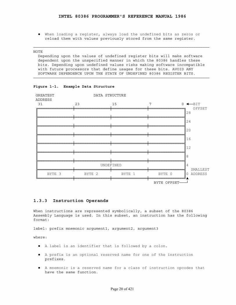
INTEL 80386 PROGRAMMER'S REFERENCE MANUAL 1986
Page 20 of 421
● When loading a register, always load the undefined bits as zeros or reload them with values previously stored from the same register.
────────────────────────────────────────────────────────────────────────────NOTE Depending upon the values of undefined register bits will make software dependent upon the unspecified manner in which the 80386 handles these bits. Depending upon undefined values risks making software incompatible with future processors that define usages for these bits. AVOID ANY SOFTWARE DEPENDENCE UPON THE STATE OF UNDEFINED 80386 REGISTER BITS.────────────────────────────────────────────────────────────────────────────
Figure 1-1. Example Data Structure
GREATEST DATA STRUCTURE ADDRESS 31 23 15 7 0 ◄──BIT ╔═══════════════╪═══════════════╪═══════════════╪═══════════════╗ OFFSET ║ ║28 ╠═══════════════╪═══════════════╪═══════════════╪═══════════════╣ ║ ║24 ╠═══════════════╪═══════════════╪═══════════════╪═══════════════╣ ║ ║20 ╠═══════════════╪═══════════════╪═══════════════╪═══════════════╣ ║ ║16 ╠═══════════════╪═══════════════╪═══════════════╪═══════════════╣ ║ ║12 ╠═══════════════╪═══════════════╪═══════════════╪═══════════════╣ ║ ║8 ╠═══════════════╪═══════════════╪═══════════════╪═══════════════╣ ║ UNDEFINED ║4 ╠═══════════════╪═══════════════╪═══════════════╪═══════════════╣ SMALLEST ║ BYTE 3 BYTE 2 BYTE 1 BYTE 0 ║0 ADDRESS ╚═══════════════╪═══════════════╪═══════════════╪═══════════════╝▲ BYTE OFFSET───┘
1.3.3 Instruction Operands
When instructions are represented symbolically, a subset of the 80386Assembly Language is used. In this subset, an instruction has the followingformat:
label: prefix mnemonic argument1, argument2, argument3
where:
● A label is an identifier that is followed by a colon.
● A prefix is an optional reserved name for one of the instruction prefixes.
● A mnemonic is a reserved name for a class of instruction opcodes that have the same function.
INTEL 80386 PROGRAMMER'S REFERENCE MANUAL 1986
Page 21 of 421
● The operands argument1, argument2, and argument3 are optional. There may be from zero to three operands, depending on the opcode. When present, they take the form of either literals or identifiers for data items. Operand identifiers are either reserved names of registers or are assumed to be assigned to data items declared in another part of the program (which may not be shown in the example). When two operands are present in an instruction that modifies data, the right operand is the source and the left operand is the destination.
For example:
LOADREG: MOV EAX, SUBTOTAL
In this example LOADREG is a label, MOV is the mnemonic identifier of anopcode, EAX is the destination operand, and SUBTOTAL is the source operand.
1.3.4 Hexadecimal Numbers
Base 16 numbers are represented by a string of hexadecimal digits followedby the character H. A hexadecimal digit is a character from the set (0, 1,2, 3, 4, 5, 6, 7, 8, 9, A, B, C, D, E, F). In some cases, especially inexamples of program syntax, a leading zero is added if the number wouldotherwise begin with one of the digits A-F. For example, 0FH is equivalentto the decimal number 15.
1.3.5 Sub- and Super-Scripts
This manual uses special notation to represent sub- and super-scriptcharacters. Sub-script characters are surrounded by {curly brackets}, forexample 10{2} = 10 base 2. Super-script characters are preceeded by acaret and enclosed within (parentheses), for example 10^(3) = 10 to thethird power.
Editors Note: This revised document provides actual super-script and sub-script characters where appropriate.

INTEL 80386 PROGRAMMER'S REFERENCE MANUAL 1986
Page 22 of 421
PART I APPLICATIONS PROGRAMMING
Chapter 2 Basic Programming Model
────────────────────────────────────────────────────────────────────────────
This chapter describes the 80386 application programming environment asseen by assembly language programmers when the processor is executing inprotected mode. The chapter introduces programmers to those features of the80386 architecture that directly affect the design and implementation of80386 applications programs. Other chapters discuss 80386 features thatrelate to systems programming or to compatibility with other processors ofthe 8086 family.
The basic programming model consists of these aspects:
● Memory organization and segmentation ● Data types ● Registers ● Instruction format ● Operand selection ● Interrupts and exceptions
Note that input/output is not included as part of the basic programmingmodel. Systems designers may choose to make I/O instructions available toapplications or may choose to reserve these functions for the operatingsystem. For this reason, the I/O features of the 80386 are discussed in PartII.
This chapter contains a section for each aspect of the architecture that isnormally visible to applications.
2.1 Memory Organization and Segmentation
The physical memory of an 80386 system is organized as a sequence of 8-bitbytes. Each byte is assigned a unique address that ranges from zero to amaximum of 232-1 (4 gigabytes).
80386 programs, however, are independent of the physical address space.This means that programs can be written without knowledge of how muchphysical memory is available and without knowledge of exactly where inphysical memory the instructions and data are located.
The model of memory organization seen by applications programmers isdetermined by systems-software designers. The architecture of the 80386gives designers the freedom to choose a model for each task. The model ofmemory organization can range between the following extremes:
● A "flat" address space consisting of a single array of up to 4 gigabytes.
INTEL 80386 PROGRAMMER'S REFERENCE MANUAL 1986
Page 23 of 421
● A segmented address space consisting of a collection of up to 16,383 linear address spaces of up to 4 gigabytes each.
Both models can provide memory protection. Different tasks may employdifferent models of memory organization. The criteria that designers use todetermine a memory organization model and the means that systems programmersuse to implement that model are covered in Part II──Systems Programming.
2.1.1 The "Flat" Model
In a "flat" model of memory organization, the applications programmer seesa single array of up to 232 bytes (4 gigabytes). While the physicalmemory can contain up to 4 gigabytes, it is usually much smaller; theprocessor maps the 4 gigabyte flat space onto the physical address space bythe address translation mechanisms described in Chapter 5. Applicationsprogrammers do not need to know the details of the mapping.
A pointer into this flat address space is a 32-bit ordinal number that mayrange from 0 to 232-1. Relocation of separately-compiled modules in thisspace must be performed by systems software (e.g., linkers, locators,binders, loaders).
2.1.2 The Segmented Model
In a segmented model of memory organization, the address space as viewed byan applications program (called the logical address space) is a much largerspace of up to 246 bytes (64 terabytes). The processor maps the 64terabyte logical address space onto the physical address space (up to 4gigabytes) by the address translation mechanisms described in Chapter 5.Applications programmers do not need to know the details of this mapping.
Applications programmers view the logical address space of the 80386 as acollection of up to 16,383 one-dimensional subspaces, each with a specifiedlength. Each of these linear subspaces is called a segment. A segment is aunit of contiguous address space. Segment sizes may range from one byte upto a maximum of 232 bytes (4 gigabytes).
A complete pointer in this address space consists of two parts (see Figure2-1):
1. A segment selector, which is a 16-bit field that identifies a segment.
2. An offset, which is a 32-bit ordinal that addresses to the byte level within a segment.
During execution of a program, the processor associates with a segmentselector the physical address of the beginning of the segment. Separatelycompiled modules can be relocated at run time by changing the base addressof their segments. The size of a segment is variable; therefore, a segmentcan be exactly the size of the module it contains.
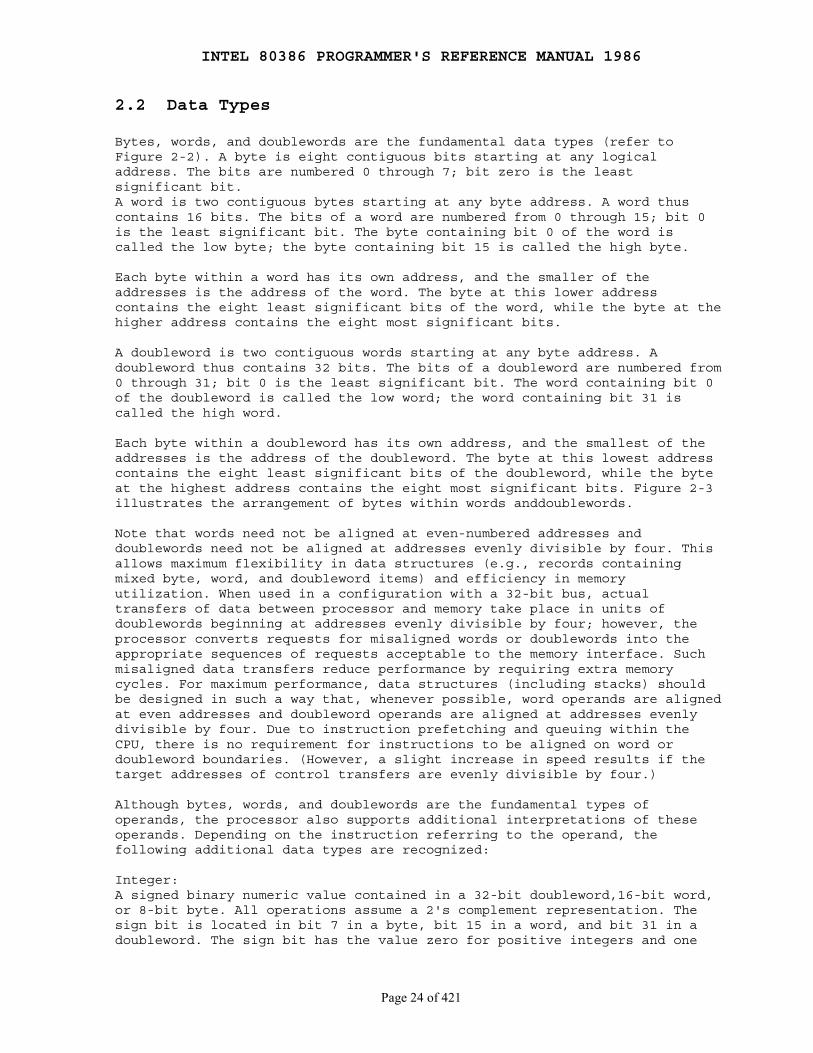
INTEL 80386 PROGRAMMER'S REFERENCE MANUAL 1986
Page 24 of 421
2.2 Data Types
Bytes, words, and doublewords are the fundamental data types (refer toFigure 2-2). A byte is eight contiguous bits starting at any logicaladdress. The bits are numbered 0 through 7; bit zero is the leastsignificant bit.A word is two contiguous bytes starting at any byte address. A word thuscontains 16 bits. The bits of a word are numbered from 0 through 15; bit 0is the least significant bit. The byte containing bit 0 of the word iscalled the low byte; the byte containing bit 15 is called the high byte.
Each byte within a word has its own address, and the smaller of theaddresses is the address of the word. The byte at this lower addresscontains the eight least significant bits of the word, while the byte at thehigher address contains the eight most significant bits.
A doubleword is two contiguous words starting at any byte address. Adoubleword thus contains 32 bits. The bits of a doubleword are numbered from0 through 31; bit 0 is the least significant bit. The word containing bit 0of the doubleword is called the low word; the word containing bit 31 iscalled the high word.
Each byte within a doubleword has its own address, and the smallest of theaddresses is the address of the doubleword. The byte at this lowest addresscontains the eight least significant bits of the doubleword, while the byteat the highest address contains the eight most significant bits. Figure 2-3illustrates the arrangement of bytes within words anddoublewords.
Note that words need not be aligned at even-numbered addresses anddoublewords need not be aligned at addresses evenly divisible by four. Thisallows maximum flexibility in data structures (e.g., records containingmixed byte, word, and doubleword items) and efficiency in memoryutilization. When used in a configuration with a 32-bit bus, actualtransfers of data between processor and memory take place in units ofdoublewords beginning at addresses evenly divisible by four; however, theprocessor converts requests for misaligned words or doublewords into theappropriate sequences of requests acceptable to the memory interface. Suchmisaligned data transfers reduce performance by requiring extra memorycycles. For maximum performance, data structures (including stacks) shouldbe designed in such a way that, whenever possible, word operands are alignedat even addresses and doubleword operands are aligned at addresses evenlydivisible by four. Due to instruction prefetching and queuing within theCPU, there is no requirement for instructions to be aligned on word ordoubleword boundaries. (However, a slight increase in speed results if thetarget addresses of control transfers are evenly divisible by four.)
Although bytes, words, and doublewords are the fundamental types ofoperands, the processor also supports additional interpretations of theseoperands. Depending on the instruction referring to the operand, thefollowing additional data types are recognized:
Integer:A signed binary numeric value contained in a 32-bit doubleword,16-bit word,or 8-bit byte. All operations assume a 2's complement representation. Thesign bit is located in bit 7 in a byte, bit 15 in a word, and bit 31 in adoubleword. The sign bit has the value zero for positive integers and one

INTEL 80386 PROGRAMMER'S REFERENCE MANUAL 1986
Page 25 of 421
for negative. Since the high-order bit is used for a sign, the range of an8-bit integer is -128 through +127; 16-bit integers may range from -32,768through +32,767; 32-bit integers may range from -231 through +231-1.The value zero has a positive sign.
Ordinal:An unsigned binary numeric value contained in a 32-bit doubleword,16-bit word, or 8-bit byte. All bits are considered in determiningmagnitude of the number. The value range of an 8-bit ordinal numberis 0-255; 16 bits can represent values from 0 through 65,535; 32 bitscan represent values from 0 through 232-1.
Near Pointer:A 32-bit logical address. A near pointer is an offset within a segment.Near pointers are used in either a flat or a segmented model of memoryorganization.
Far Pointer:A 48-bit logical address of two components: a 16-bit segment selectorcomponent and a 32-bit offset component. Far pointers are used byapplications programmers only when systems designers choose asegmented memory organization.
String:A contiguous sequence of bytes, words, or doublewords. A string maycontain from zero bytes to 232-1 bytes (4 gigabytes).
Bit field:A contiguous sequence of bits. A bit field may begin at any bit positionof any byte and may contain up to 32 bits.
Bit string:A contiguous sequence of bits. A bit string may begin at any bit positionof any byte and may contain up to 232-1 bits.
BCD:A byte (unpacked) representation of a decimal digit in the range0 through9. Unpacked decimal numbers are stored as unsigned byte quantities. Onedigit is stored in each byte. The magnitude of the number is determined fromthe low-order half-byte; hexadecimal values 0-9 are valid and areinterpreted as decimal numbers. The high-order half-byte must be zero formultiplication and division; it may contain any value for addition andsubtraction.
Packed BCD:A byte (packed) representation of two decimal digits, each in the range0 through 9. One digit is stored in each half-byte. The digit in thehigh-order half-byte is the most significant. Values 0-9 are valid in eachhalf-byte. The range of a packed decimal byte is 0-99.
Figure 2-4 graphically summarizes the data types supported by the 80386.

INTEL 80386 PROGRAMMER'S REFERENCE MANUAL 1986
Page 26 of 421
Figure 2-1. Two-Component Pointer
· · ║ ║ ╠═══════════════╣─┐ 32 0 ║ ║ │ ╔═══════╪═══════╗ ╔═══╗ ╠═══════════════╣ │ ║ OFFSET ╟───╢ + ╟───►║ OPERAND ║ │ ╚═══════╪═══════╝ ╚═══╝ ╠═══════════════╣ ├─ SELECTED SEGMENT ▲ ║ ║ │ 16 0 │ ║ ║ │ ╔═══════╗ │ ║ ║ │ ║SEGMENT╟─────────·─────►╠═══════════════╣─┘ ╚═══════╝ ║ ║ ║ ║ ║ ║ · ·
Figure 2-2. Fundamental Data Types
7 0 ╔═══════════════╗ ║ BYTE ║ BYTE ╚═══════════════╝
15 7 0 ╔═══════════════╤═══════════════╗ ║ HIGH BYTE │ LOW BYTE ║ WORD ╚═══════════════╧═══════════════╝ address n+1 address n
31 23 15 7 0 ╔═══════════════╪═══════════════╪═══════════════╪══════════════╗ ║ HIGH WORD │ LOW WORD ║ DOUBLEWORD ╚═══════════════╪═══════════════╪═══════════════╪══════════════╝ address n+3 address n+2 address n+1 address n
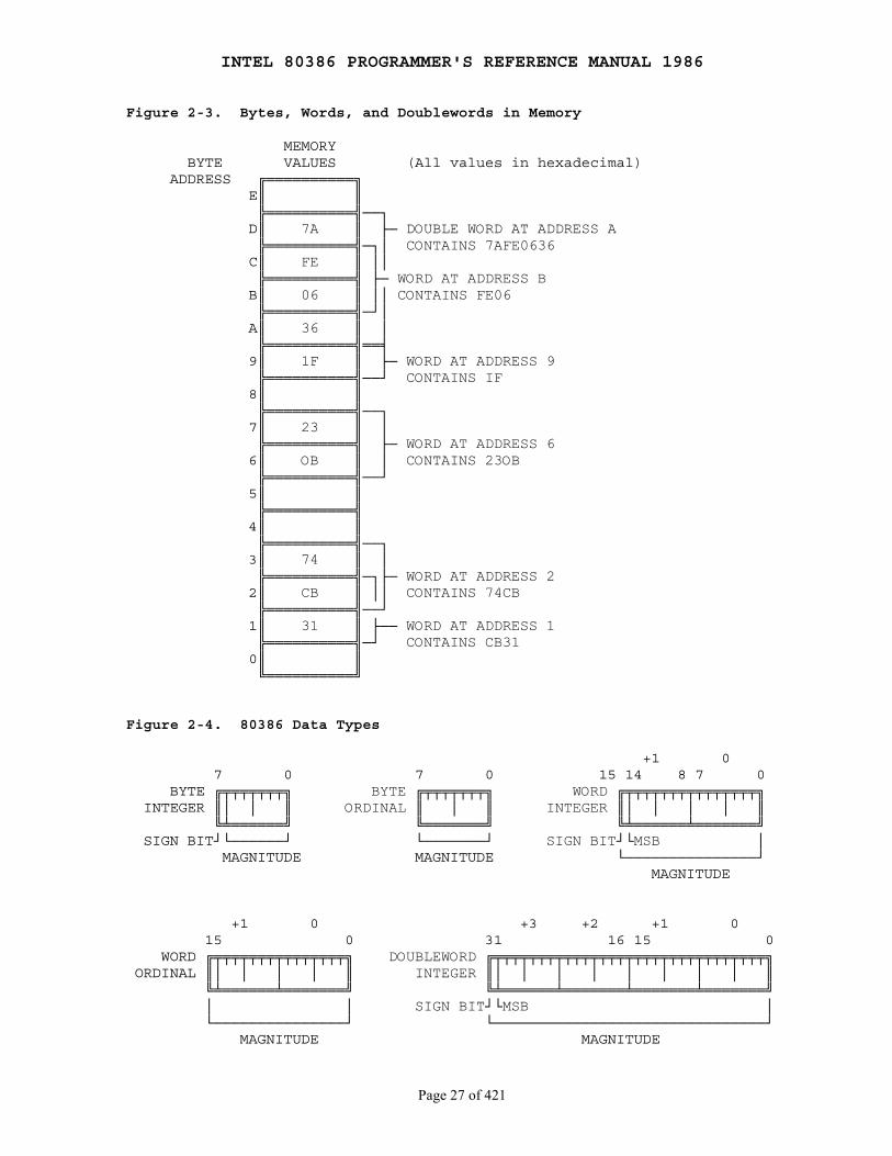
INTEL 80386 PROGRAMMER'S REFERENCE MANUAL 1986
Page 27 of 421
Figure 2-3. Bytes, Words, and Doublewords in Memory
MEMORY BYTE VALUES (All values in hexadecimal) ADDRESS ╔══════════╗ E║ ║ ╠══════════╣──┐ D║ 7A ║ ├─ DOUBLE WORD AT ADDRESS A ╠══════════╣─┐│ CONTAINS 7AFE0636 C║ FE ║ ││ ╠══════════╣ ├─ WORD AT ADDRESS B B║ 06 ║ ││ CONTAINS FE06 ╠══════════╣─┘│ A║ 36 ║ │ ╠══════════╣══╡ 9║ 1F ║ ├─ WORD AT ADDRESS 9 ╠══════════╣──┘ CONTAINS IF 8║ ║ ╠══════════╣──┐ 7║ 23 ║ │ ╠══════════╣ ├─ WORD AT ADDRESS 6 6║ OB ║ │ CONTAINS 23OB ╠══════════╣──┘ 5║ ║ ╠══════════╣ 4║ ║ ╠══════════╣──┐ 3║ 74 ║ │ ╠══════════╣─┐├─ WORD AT ADDRESS 2 2║ CB ║ ││ CONTAINS 74CB ╠══════════╣──┘ 1║ 31 ║ ├── WORD AT ADDRESS 1 ╠══════════╣─┘ CONTAINS CB31 0║ ║ ╚══════════╝
Figure 2-4. 80386 Data Types
+1 0 7 0 7 0 15 14 8 7 0 BYTE ╔╤╤╤╤╤╤╤╗ BYTE ╔╤╤╤╤╤╤╤╗ WORD ╔╤╤╤╤╤╤╤╤╤╤╤╤╤╤╤╗ INTEGER ║│ │ ║ ORDINAL ║ │ ║ INTEGER ║│ │ │ │ ║ ╚╧══════╝ ╚═══════╝ ╚╧══════╧═══════╝ SIGN BIT┘└──────┘ └───────┘ SIGN BIT┘└MSB │ MAGNITUDE MAGNITUDE └───────────────┘ MAGNITUDE
+1 0 +3 +2 +1 0 15 0 31 16 15 0 WORD ╔╤╤╤╤╤╤╤╤╤╤╤╤╤╤╤╗ DOUBLEWORD ╔╤╤╤╤╤╤╤╤╤╤╤╤╤╤╤╤╤╤╤╤╤╤╤╤╤╤╤╤╤╤╤╗ ORDINAL ║│ │ │ │ ║ INTEGER ║│ │ │ │ │ │ │ │ ║ ╚╧══════╧═══════╝ ╚╧══════╧═══════╧═══════╧═══════╝ │ │ SIGN BIT┘└MSB │ └───────────────┘ └───────────────────────────────┘ MAGNITUDE MAGNITUDE
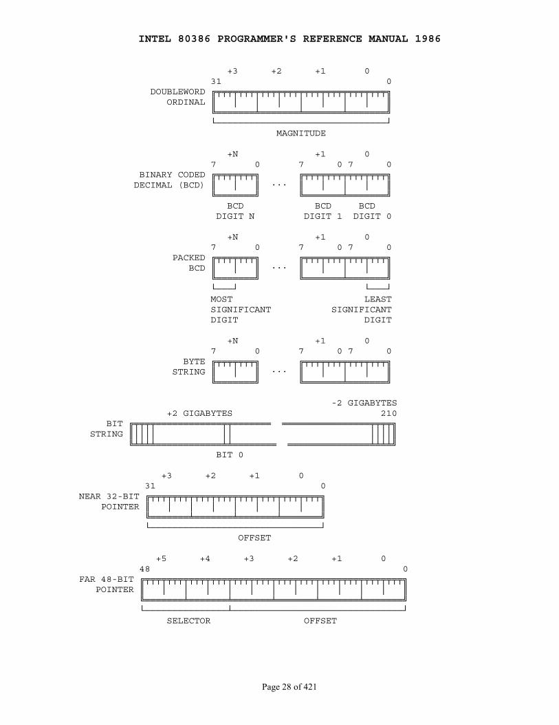
INTEL 80386 PROGRAMMER'S REFERENCE MANUAL 1986
Page 28 of 421
+3 +2 +1 0 31 0 DOUBLEWORD ╔╤╤╤╤╤╤╤╤╤╤╤╤╤╤╤╤╤╤╤╤╤╤╤╤╤╤╤╤╤╤╤╗ ORDINAL ║ │ │ │ │ │ │ │ ║ ╚═══════╧═══════╧═══════╧═══════╝ └───────────────────────────────┘ MAGNITUDE
+N +1 0 7 0 7 0 7 0 BINARY CODED ╔╤╤╤╤╤╤╤╗ ╔╤╤╤╤╤╤╤╤╤╤╤╤╤╤╤╗ DECIMAL (BCD) ║ │ ║ ··· ║ │ │ │ ║ ╚═══════╝ ╚═══════╧═══════╝ BCD BCD BCD DIGIT N DIGIT 1 DIGIT 0
+N +1 0 7 0 7 0 7 0 PACKED ╔╤╤╤╤╤╤╤╗ ╔╤╤╤╤╤╤╤╤╤╤╤╤╤╤╤╗ BCD ║ │ ║ ··· ║ │ │ │ ║ ╚═══════╝ ╚═══════╧═══════╝ └───┘ └───┘ MOST LEAST SIGNIFICANT SIGNIFICANT DIGIT DIGIT
+N +1 0 7 0 7 0 7 0 BYTE ╔╤╤╤╤╤╤╤╗ ╔╤╤╤╤╤╤╤╤╤╤╤╤╤╤╤╗ STRING ║ │ ║ ··· ║ │ │ │ ║ ╚═══════╝ ╚═══════╧═══════╝
-2 GIGABYTES +2 GIGABYTES 210 BIT ╔╤╤╤╤════════════╤╤═══════ ════════════════╤╤╤╤╗ STRING ║││││ ││ ││││║ ╚╧╧╧╧════════════╧╧════════ ═══════════════╧╧╧╧╝ BIT 0
+3 +2 +1 0 31 0NEAR 32-BIT ╔╤╤╤╤╤╤╤╤╤╤╤╤╤╤╤╤╤╤╤╤╤╤╤╤╤╤╤╤╤╤╤╗ POINTER ║ │ │ │ │ │ │ │ ║ ╚═══════╧═══════╧═══════╧═══════╝ └───────────────────────────────┘ OFFSET
+5 +4 +3 +2 +1 0 48 0FAR 48-BIT ╔╤╤╤╤╤╤╤╤╤╤╤╤╤╤╤╤╤╤╤╤╤╤╤╤╤╤╤╤╤╤╤╤╤╤╤╤╤╤╤╤╤╤╤╤╤╤╤╗ POINTER ║ │ │ │ │ │ │ │ │ │ │ │ ║ ╚═══════╧═══════╧═══════╧═══════╧═══════╧═══════╝ └───────────────┴───────────────────────────────┘ SELECTOR OFFSET
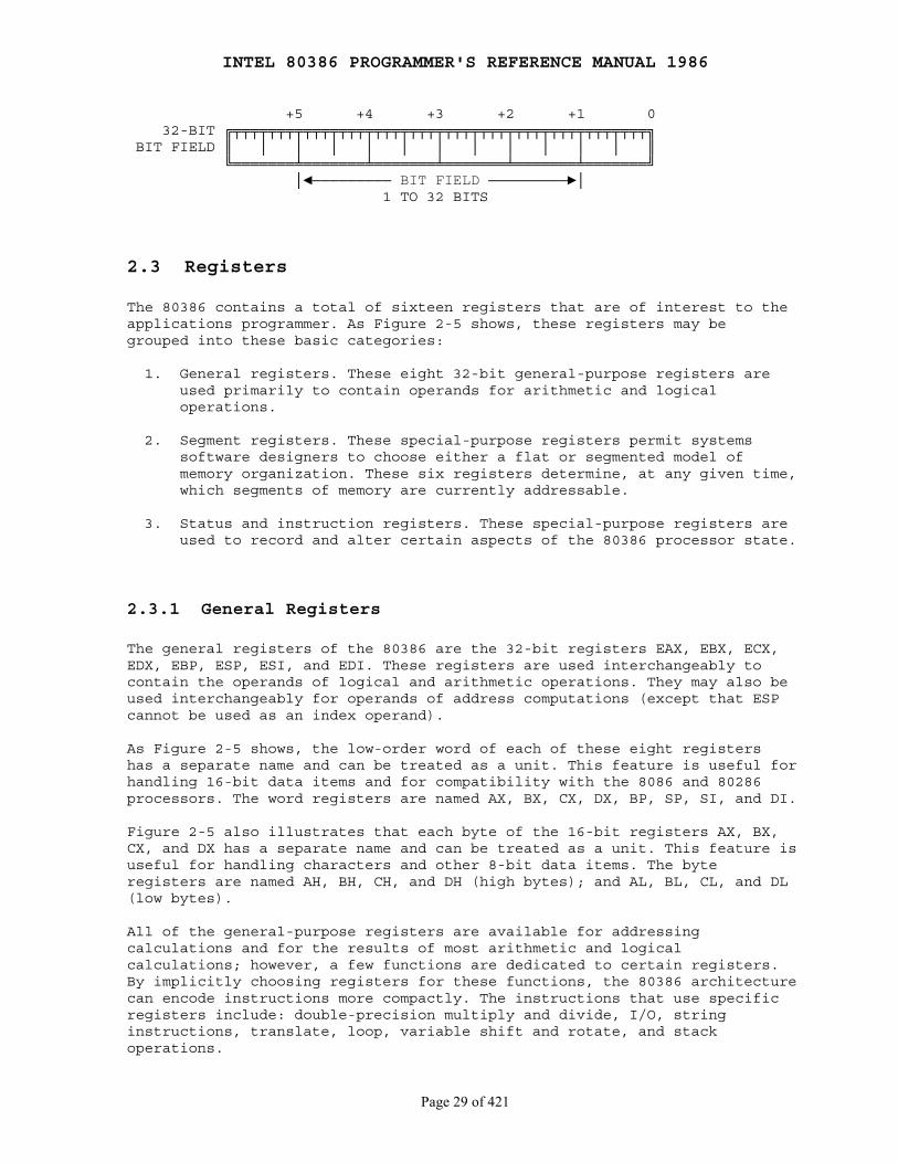
INTEL 80386 PROGRAMMER'S REFERENCE MANUAL 1986
Page 29 of 421
+5 +4 +3 +2 +1 0 32-BIT ╔╤╤╤╤╤╤╤╤╤╤╤╤╤╤╤╤╤╤╤╤╤╤╤╤╤╤╤╤╤╤╤╤╤╤╤╤╤╤╤╤╤╤╤╤╤╤╤╗ BIT FIELD ║ │ │ │ │ │ │ │ │ │ │ │ ║ ╚═══════╧═══════╧═══════╧═══════╧═══════╧═══════╝ │◄───────── BIT FIELD ─────────►│ 1 TO 32 BITS
2.3 Registers
The 80386 contains a total of sixteen registers that are of interest to theapplications programmer. As Figure 2-5 shows, these registers may begrouped into these basic categories:
1. General registers. These eight 32-bit general-purpose registers are used primarily to contain operands for arithmetic and logical operations.
2. Segment registers. These special-purpose registers permit systems software designers to choose either a flat or segmented model of memory organization. These six registers determine, at any given time, which segments of memory are currently addressable.
3. Status and instruction registers. These special-purpose registers are used to record and alter certain aspects of the 80386 processor state.
2.3.1 General Registers
The general registers of the 80386 are the 32-bit registers EAX, EBX, ECX,EDX, EBP, ESP, ESI, and EDI. These registers are used interchangeably tocontain the operands of logical and arithmetic operations. They may also beused interchangeably for operands of address computations (except that ESPcannot be used as an index operand).
As Figure 2-5 shows, the low-order word of each of these eight registershas a separate name and can be treated as a unit. This feature is useful forhandling 16-bit data items and for compatibility with the 8086 and 80286processors. The word registers are named AX, BX, CX, DX, BP, SP, SI, and DI.
Figure 2-5 also illustrates that each byte of the 16-bit registers AX, BX,CX, and DX has a separate name and can be treated as a unit. This feature isuseful for handling characters and other 8-bit data items. The byteregisters are named AH, BH, CH, and DH (high bytes); and AL, BL, CL, and DL(low bytes).
All of the general-purpose registers are available for addressingcalculations and for the results of most arithmetic and logicalcalculations; however, a few functions are dedicated to certain registers.By implicitly choosing registers for these functions, the 80386 architecturecan encode instructions more compactly. The instructions that use specificregisters include: double-precision multiply and divide, I/O, stringinstructions, translate, loop, variable shift and rotate, and stackoperations.
INTEL 80386 PROGRAMMER'S REFERENCE MANUAL 1986
Page 30 of 421
2.3.2 Segment Registers
The segment registers of the 80386 give systems software designers theflexibility to choose among various models of memory organization.Implementation of memory models is the subject of Part II ── SystemsProgramming. Designers may choose a model in which applications programs donot need to modify segment registers, in which case applications programmersmay skip this section.
Complete programs generally consist of many different modules, eachconsisting of instructions and data. However, at any given time duringprogram execution, only a small subset of a program's modules are actuallyin use. The 80386 architecture takes advantage of this by providingmechanisms to support direct access to the instructions and data of thecurrent module's environment, with access to additional segments on demand.
At any given instant, six segments of memory may be immediately accessibleto an executing 80386 program. The segment registers CS, DS, SS, ES, FS, andGS are used to identify these six current segments. Each of these registersspecifies a particular kind of segment, as characterized by the associatedmnemonics ("code," "data," or "stack") shown in Figure 2-6. Each registeruniquely determines one particular segment, from among the segments thatmake up the program, that is to be immediately accessible at highest speed.
The segment containing the currently executing sequence of instructions isknown as the current code segment; it is specified by means of the CSregister. The 80386 fetches all instructions from this code segment, usingas an offset the contents of the instruction pointer. CS is changedimplicitly as the result of intersegment control-transfer instructions (forexample, CALL and JMP), interrupts, and exceptions.
Subroutine calls, parameters, and procedure activation records usuallyrequire that a region of memory be allocated for a stack. All stackoperations use the SS register to locate the stack. Unlike CS, the SSregister can be loaded explicitly, thereby permitting programmers to definestacks dynamically.
The DS, ES, FS, and GS registers allow the specification of four datasegments, each addressable by the currently executing program. Accessibilityto four separate data areas helps programs efficiently access differenttypes of data structures; for example, one data segment register can pointto the data structures of the current module, another to the exported dataof a higher-level module, another to a dynamically created data structure,and another to data shared with another task. An operand within a datasegment is addressed by specifying its offset either directly in aninstruction or indirectly via general registers.
Depending on the structure of data (e.g., the way data is parceled into oneor more segments), a program may require access to more than four datasegments. To access additional segments, the DS, ES, FS, and GS registerscan be changed under program control during the course of a program'sexecution. This simply requires that the program execute an instruction toload the appropriate segment register prior to executing instructions thataccess the data.
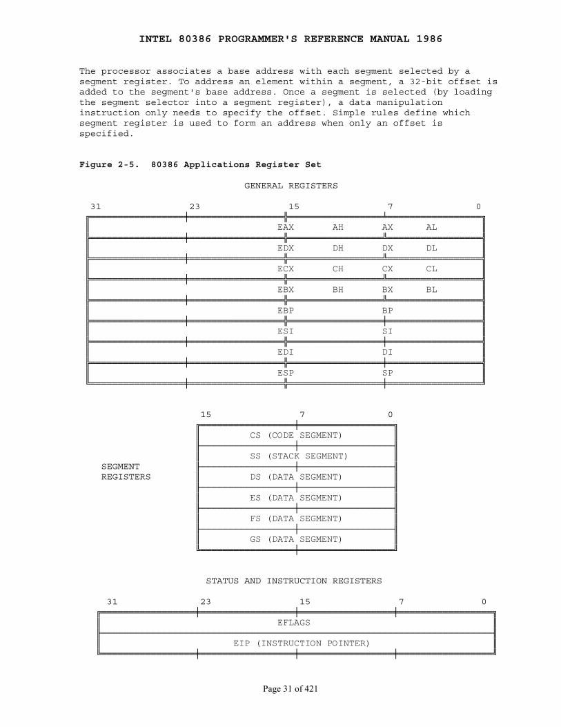
INTEL 80386 PROGRAMMER'S REFERENCE MANUAL 1986
Page 31 of 421
The processor associates a base address with each segment selected by asegment register. To address an element within a segment, a 32-bit offset isadded to the segment's base address. Once a segment is selected (by loadingthe segment selector into a segment register), a data manipulationinstruction only needs to specify the offset. Simple rules define whichsegment register is used to form an address when only an offset isspecified.
Figure 2-5. 80386 Applications Register Set
GENERAL REGISTERS
31 23 15 7 0 ╔═════════════════╪═════════════════╬═════════════════╧═════════════════╗ ║ EAX AH AX AL ║ ╠═════════════════╪═════════════════╬═════════════════╩═════════════════╣ ║ EDX DH DX DL ║ ╠═════════════════╪═════════════════╬═════════════════╩═════════════════╣ ║ ECX CH CX CL ║ ╠═════════════════╪═════════════════╬═════════════════╩═════════════════╣ ║ EBX BH BX BL ║ ╠═════════════════╪═════════════════╬═════════════════╩═════════════════╣ ║ EBP BP ║ ╠═════════════════╪═════════════════╬═════════════════╪═════════════════╣ ║ ESI SI ║ ╠═════════════════╪═════════════════╬═════════════════╪═════════════════╣ ║ EDI DI ║ ╠═════════════════╪═════════════════╬═════════════════╪═════════════════╣ ║ ESP SP ║ ╚═════════════════╪═════════════════╬═════════════════╪═════════════════╝
15 7 0 ╔═════════════════╪═════════════════╗ ║ CS (CODE SEGMENT) ║ ╟─────────────────┼─────────────────╢ ║ SS (STACK SEGMENT) ║ SEGMENT ╟─────────────────┼─────────────────╢ REGISTERS ║ DS (DATA SEGMENT) ║ ╟─────────────────┼─────────────────╢ ║ ES (DATA SEGMENT) ║ ╟─────────────────┼─────────────────╢ ║ FS (DATA SEGMENT) ║ ╟─────────────────┼─────────────────╢ ║ GS (DATA SEGMENT) ║ ╚═════════════════╪═════════════════╝
STATUS AND INSTRUCTION REGISTERS
31 23 15 7 0 ╔═════════════════╪═════════════════╪═════════════════╪═════════════════╗ ║ EFLAGS ║ ╟───────────────────────────────────────────────────────────────────────╢ ║ EIP (INSTRUCTION POINTER) ║ ╚═════════════════╪═════════════════╪═════════════════╪═════════════════╝

INTEL 80386 PROGRAMMER'S REFERENCE MANUAL 1986
Page 32 of 421
Figure 2-6. Use of Memory Segmentation
╔════════════════╗ ╔════════════════╗ ║ MODULE ║ ║ MODULE ║ ║ A ║◄──┐ ┌──►║ A ║ ║ CODE ║ │ │ ║ DATA ║ ╚════════════════╝ │ ╔══════════════════╗ │ ╚════════════════╝ └──╢ CS (CODE) ║ │ ╠══════════════════╣ │ ╔════════════════╗ ┌──╢ SS (STACK) ║ │ ╔════════════════╗ ║ ║ │ ╠══════════════════╣ │ ║ DATA ║ ║ STACK ║◄──┘ ║ DS (DATA) ╟──┘┌─►║ STRUCTURE ║ ║ ║ ╠══════════════════╣ │ ║ 1 ║ ╚════════════════╝ ║ ES (DATA) ╟───┘ ╚════════════════╝ ╠══════════════════╣ ┌──╢ FS (DATA) ║ ╔════════════════╗ │ ╠══════════════════╣ ╔════════════════╗ ║ DATA ║ │ ║ GS (DATA) ╟──┐ ║ DATA ║ ║ STRUCTURE ║◄──┘ ╚══════════════════╝ └──►║ STRUCTURE ║ ║ 2 ║ ║ 3 ║ ╚════════════════╝ ╚════════════════╝
2.3.3 Stack Implementation
Stack operations are facilitated by three registers:
1. The stack segment (SS) register. Stacks are implemented in memory. A system may have a number of stacks that is limited only by the maximum number of segments. A stack may be up to 4 gigabytes long, the maximum length of a segment. One stack is directly addressable at a time──the one located by SS. This is the current stack, often referred to simply as "the" stack. SS is used automatically by the processor for all stack operations.
2. The stack pointer (ESP) register. ESP points to the top of the push-down stack (TOS). It is referenced implicitly by PUSH and POP operations, subroutine calls and returns, and interrupt operations. When an item is pushed onto the stack (see Figure 2-7), the processor decrements ESP, then writes the item at the new TOS. When an item is popped off the stack, the processor copies it from TOS, then increments ESP. In other words, the stack grows down in memory toward lesser addresses.
3. The stack-frame base pointer (EBP) register. The EBP is the best choice of register for accessing data structures, variables and dynamically allocated work space within the stack. EBP is often used to access elements on the stack relative to a fixed point on the stack rather than relative to the current TOS. It typically identifies the base address of the current stack frame established for the current procedure. When EBP is used as the base register in an offset calculation, the offset is calculated automatically in the current stack segment (i.e., the segment currently selected by SS). Because

INTEL 80386 PROGRAMMER'S REFERENCE MANUAL 1986
Page 33 of 421
SS does not have to be explicitly specified, instruction encoding in such cases is more efficient. EBP can also be used to index into segments addressable via other segment registers.
Figure 2-7. 80386 Stack
31 0 ╔══════╪══════╪══════╪══════╗ ◄───────BOTTOM OF STACK ║ ║ (INITIAL ESP VALUE) ╟══════╪══════╪══════╪══════╣ ║ ║ ╠══════╪══════╪══════╪══════╣ ▲ ║ ║ │POP ╠══════╪══════╪══════╪══════╣ │ ║ ║ │ ╠══════╪══════╪══════╪══════╣ │ TOP OF ╔═════════════╗ ║ ║ ◄──────┼─────────────────╢ ESP ║ ╠══════╪══════╪══════╪══════╣ │ STACK ╚═════════════╝ ║ ║ │ ║ ║ │ ║ ║ │PUSH ║ ║ ▼
2.3.4 Flags Register
The flags register is a 32-bit register named EFLAGS. Figure 2-8 definesthe bits within this register. The flags control certain operations andindicate the status of the 80386.
The low-order 16 bits of EFLAGS is named FLAGS and can be treated as aunit. This feature is useful when executing 8086 and 80286 code, becausethis part of EFLAGS is identical to the FLAGS register of the 8086 and the80286.
The flags may be considered in three groups: the status flags, the controlflags, and the systems flags. Discussion of the systems flags is delayeduntil Part II.

INTEL 80386 PROGRAMMER'S REFERENCE MANUAL 1986
Page 34 of 421
Figure 2-8. EFLAGS Register
16-BIT FLAGS REGISTER A ┌───────────────────┴───────────────┐ 31 23 15 7 0 ╔═══════════════════╪═══════════════╤═╤═╤═╤═╤═╪═╤═╤═╤═╤═╤═╤═╤═╤═╤═╤═╤═╤═╗ ║ │V│R│ │N│ IO│O│D│I│T│S│Z│ │A│ │P│ │C║ ║ 0 0 0 0 0 0 0 0 0 0 0 0 0 0 0 0 0 │ │ │0│ │ │ │ │ │ │ │ │0│ │0│ │1│ ║ ║ │M│F│ │T│ PL│F│F│F│F│F│F│ │F│ │F│ │F║ ╚═══════════════════╪═══════════════╧╤╧╤╧═╧╤╧═╪═╧╤╧╤╧╤╧╤╧╤╧╤╧═╧╤╧═╧╤╧═╧╤╝ │ │ │ │ │ │ │ │ │ │ │ │ │ VIRTUAL 8086 MODE───X──────────┘ │ │ │ │ │ │ │ │ │ │ │ │ RESUME FLAG───X────────────┘ │ │ │ │ │ │ │ │ │ │ │ NESTED TASK FLAG───X────────────────┘ │ │ │ │ │ │ │ │ │ │ I/O PRIVILEGE LEVEL───X───────────────────┘ │ │ │ │ │ │ │ │ │ OVERFLOW───S──────────────────────┘ │ │ │ │ │ │ │ │ DIRECTION FLAG───C────────────────────────┘ │ │ │ │ │ │ │ INTERRUPT ENABLE───X──────────────────────────┘ │ │ │ │ │ │ TRAP FLAG───S────────────────────────────┘ │ │ │ │ │ SIGN FLAG───S──────────────────────────────┘ │ │ │ │ ZERO FLAG───S────────────────────────────────┘ │ │ │ AUXILIARY CARRY───S────────────────────────────────────┘ │ │ PARITY FLAG───S────────────────────────────────────────┘ │ CARRY FLAG───S────────────────────────────────────────────┘
S = STATUS FLAG, C = CONTROL FLAG, X = SYSTEM FLAG
NOTE: 0 OR 1 INDICATES INTEL RESERVED. DO NOT DEFINE
2.3.4.1 Status Flags
The status flags of the EFLAGS register allow the results of oneinstruction to influence later instructions. The arithmetic instructions useOF, SF, ZF, AF, PF, and CF. The SCAS (Scan String), CMPS (Compare String),and LOOP instructions use ZF to signal that their operations are complete.There are instructions to set, clear, and complement CF before execution ofan arithmetic instruction. Refer to Appendix C for definition of eachstatus flag.
2.3.4.2 Control Flag
The control flag DF of the EFLAGS register controls string instructions.
DF (Direction Flag, bit 10)
Setting DF causes string instructions to auto-decrement; that is, to process strings from high addresses to low addresses. Clearing DF causes string instructions to auto-increment, or to process strings from low addresses to high addresses.
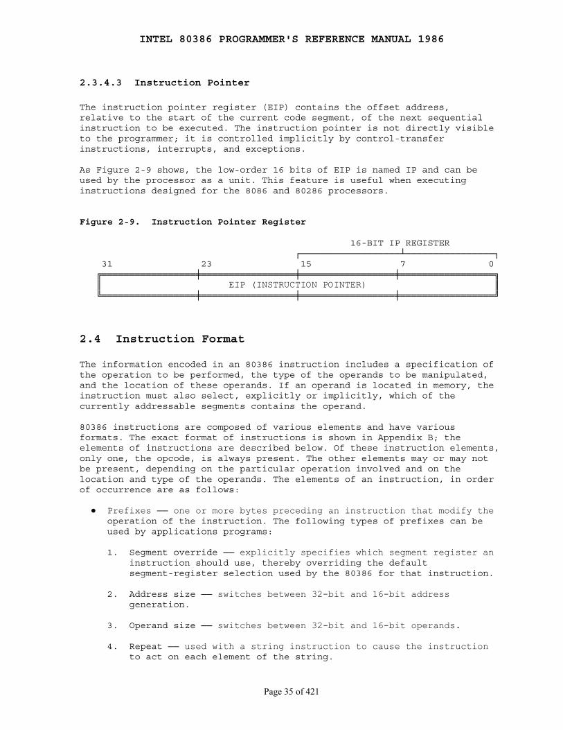
INTEL 80386 PROGRAMMER'S REFERENCE MANUAL 1986
Page 35 of 421
2.3.4.3 Instruction Pointer
The instruction pointer register (EIP) contains the offset address,relative to the start of the current code segment, of the next sequentialinstruction to be executed. The instruction pointer is not directly visibleto the programmer; it is controlled implicitly by control-transferinstructions, interrupts, and exceptions.
As Figure 2-9 shows, the low-order 16 bits of EIP is named IP and can beused by the processor as a unit. This feature is useful when executinginstructions designed for the 8086 and 80286 processors.
Figure 2-9. Instruction Pointer Register
16-BIT IP REGISTER ┌──────────────────┴────────────────┐ 31 23 15 7 0 ╔═════════════════╪═════════════════╪═════════════════╪═════════════════╗ ║ EIP (INSTRUCTION POINTER) ║ ╚═════════════════╪═════════════════╪═════════════════╪═════════════════╝
2.4 Instruction Format
The information encoded in an 80386 instruction includes a specification ofthe operation to be performed, the type of the operands to be manipulated,and the location of these operands. If an operand is located in memory, theinstruction must also select, explicitly or implicitly, which of thecurrently addressable segments contains the operand.
80386 instructions are composed of various elements and have variousformats. The exact format of instructions is shown in Appendix B; theelements of instructions are described below. Of these instruction elements,only one, the opcode, is always present. The other elements may or may notbe present, depending on the particular operation involved and on thelocation and type of the operands. The elements of an instruction, in orderof occurrence are as follows:
● Prefixes ── one or more bytes preceding an instruction that modify the operation of the instruction. The following types of prefixes can be used by applications programs:
1. Segment override ── explicitly specifies which segment register an instruction should use, thereby overriding the default segment-register selection used by the 80386 for that instruction.
2. Address size ── switches between 32-bit and 16-bit address generation.
3. Operand size ── switches between 32-bit and 16-bit operands.
4. Repeat ── used with a string instruction to cause the instruction to act on each element of the string.
INTEL 80386 PROGRAMMER'S REFERENCE MANUAL 1986
Page 36 of 421
● Opcode ── specifies the operation performed by the instruction. Some operations have several different opcodes, each specifying a different variant of the operation.
● Register specifier ── an instruction may specify one or two register operands. Register specifiers may occur either in the same byte as the opcode or in the same byte as the addressing-mode specifier.
● Addressing-mode specifier ── when present, specifies whether an operand is a register or memory location; if in memory, specifies whether a displacement, a base register, an index register, and scaling are to be used.
● SIB (scale, index, base) byte ── when the addressing-mode specifier indicates that an index register will be used to compute the address of an operand, an SIB byte is included in the instruction to encode the base register, the index register, and a scaling factor.
● Displacement ── when the addressing-mode specifier indicates that a displacement will be used to compute the address of an operand, the displacement is encoded in the instruction. A displacement is a signed integer of 32, 16, or eight bits. The eight-bit form is used in the common case when the displacement is sufficiently small. The processor extends an eight-bit displacement to 16 or 32 bits, taking into account the sign.
● Immediate operand ── when present, directly provides the value of an operand of the instruction. Immediate operands may be 8, 16, or 32 bits wide. In cases where an eight-bit immediate operand is combined in some way with a 16- or 32-bit operand, the processor automatically extends the size of the eight-bit operand, taking into account the sign.
2.5 Operand Selection
An instruction can act on zero or more operands, which are the datamanipulated by the instruction. An example of a zero-operand instruction isNOP (no operation). An operand can be in any of these locations:
● In the instruction itself (an immediate operand)
● In a register (EAX, EBX, ECX, EDX, ESI, EDI, ESP, or EBP in the case of 32-bit operands; AX, BX, CX, DX, SI, DI, SP, or BP in the case of 16-bit operands; AH, AL, BH, BL, CH, CL, DH, or DL in the case of 8-bit operands; the segment registers; or the EFLAGS register for flag operations)
● In memory
● At an I/O port
Immediate operands and operands in registers can be accessed more rapidlythan operands in memory since memory operands must be fetched from memory.Register operands are available in the CPU. Immediate operands are alsoavailable in the CPU, because they are prefetched as part of theinstruction.

INTEL 80386 PROGRAMMER'S REFERENCE MANUAL 1986
Page 37 of 421
Of the instructions that have operands, some specify operands implicitly;others specify operands explicitly; still others use a combination ofimplicit and explicit specification; for example:
Implicit operand: AAM
By definition, AAM (ASCII adjust for multiplication) operates on the contents of the AX register.
Explicit operand: XCHG EAX, EBX
The operands to be exchanged are encoded in the instruction after the opcode.
Implicit and explicit operands: PUSH COUNTER
The memory variable COUNTER (the explicit operand) is copied to the top of the stack (the implicit operand).
Note that most instructions have implicit operands. All arithmeticinstructions, for example, update the EFLAGS register.
An 80386 instruction can explicitly reference one or two operands.Two-operand instructions, such as MOV, ADD, XOR, etc., generally overwriteone of the two participating operands with the result. A distinction canthus be made between the source operand (the one unaffected by theoperation) and the destination operand (the one overwritten by the result).
For most instructions, one of the two explicitly specified operands──eitherthe source or the destination──can be either in a register or in memory.The other operand must be in a register or be an immediate source operand.Thus, the explicit two-operand instructions of the 80386 permit operationsof the following kinds:
● Register-to-register ● Register-to-memory ● Memory-to-register ● Immediate-to-register ● Immediate-to-memory
Certain string instructions and stack manipulation instructions, however,transfer data from memory to memory. Both operands of some stringinstructions are in memory and are implicitly specified. Push and pop stackoperations allow transfer between memory operands and the memory-basedstack.
2.5.1 Immediate Operands
Certain instructions use data from the instruction itself as one (andsometimes two) of the operands. Such an operand is called an immediateoperand. The operand may be 32-, 16-, or 8-bits long. For example:
SHR PATTERN, 2
INTEL 80386 PROGRAMMER'S REFERENCE MANUAL 1986
Page 38 of 421
One byte of the instruction holds the value 2, the number of bits by whichto shift the variable PATTERN.
TEST PATTERN, 0FFFF00FFH
A doubleword of the instruction holds the mask that is used to test thevariable PATTERN.
2.5.2 Register Operands
Operands may be located in one of the 32-bit general registers (EAX, EBX,ECX, EDX, ESI, EDI, ESP, or EBP), in one of the 16-bit general registers(AX, BX, CX, DX, SI, DI, SP, or BP), or in one of the 8-bit generalregisters (AH, BH, CH, DH, AL, BL, CL,or DL).
The 80386 has instructions for referencing the segment registers (CS, DS,ES, SS, FS, GS). These instructions are used by applications programs onlyif systems designers have chosen a segmented memory model.
The 80386 also has instructions for referring to the flag register. Theflags may be stored on the stack and restored from the stack. Certaininstructions change the commonly modified flags directly in the EFLAGSregister. Other flags that are seldom modified can be modified indirectlyvia the flags image in the stack.
2.5.3 Memory Operands
Data-manipulation instructions that address operands in memory must specify(either directly or indirectly) the segment that contains the operand andthe offset of the operand within the segment. However, for speed and compactinstruction encoding, segment selectors are stored in the high speed segmentregisters. Therefore, data-manipulation instructions need to specify onlythe desired segment register and an offset in order to address a memoryoperand.
An 80386 data-manipulation instruction that accesses memory uses one of thefollowing methods for specifying the offset of a memory operand within itssegment:
1. Most data-manipulation instructions that access memory contain a byte that explicitly specifies the addressing method for the operand. A byte, known as the modR/M byte, follows the opcode and specifies whether the operand is in a register or in memory. If the operand is in memory, the address is computed from a segment register and any of the following values: a base register, an index register, a scaling factor, a displacement. When an index register is used, the modR/M byte is also followed by another byte that identifies the index register and scaling factor. This addressing method is the mostflexible.
INTEL 80386 PROGRAMMER'S REFERENCE MANUAL 1986
Page 39 of 421
2. A few data-manipulation instructions implicitly use specialized addressing methods:
● For a few short forms of MOV that implicitly use the EAX register, the offset of the operand is coded as a doubleword in the instruction. No base register, index register, or scaling factor are used.
● String operations implicitly address memory via DS:ESI, (MOVS, CMPS, OUTS, LODS, SCAS) or via ES:EDI (MOVS, CMPS, INS, STOS).
● Stack operations implicitly address operands via SS:ESP registers; e.g., PUSH, POP, PUSHA, PUSHAD, POPA, POPAD, PUSHF, PUSHFD, POPF, POPFD, CALL, RET, IRET, IRETD, exceptions, and interrupts.
2.5.3.1 Segment Selection
Data-manipulation instructions need not explicitly specify which segmentregister is used. For all of these instructions, specification of a segmentregister is optional. For all memory accesses, if a segment is notexplicitly specified by the instruction, the processor automatically choosesa segment register according to the rules of Table 2-1. (If systemsdesigners have chosen a flat model of memory organization, the segmentregisters and the rules that the processor uses in choosing them are notapparent to applications programs.)
There is a close connection between the kind of memory reference and thesegment in which that operand resides. As a rule, a memory reference impliesthe current data segment (i.e., the implicit segment selector is in DS).However, ESP and EBP are used to access items on the stack; therefore, whenthe ESP or EBP register is used as a base register, the current stacksegment is implied (i.e., SS contains the selector).
Special instruction prefix elements may be used to override the defaultsegment selection. Segment-override prefixes allow an explicit segmentselection. The 80386 has a segment-override prefix for each of the segmentregisters. Only in the following special cases is there an implied segmentselection that a segment prefix cannot override:
● The use of ES for destination strings in string instructions. ● The use of SS in stack instructions. ● The use of CS for instruction fetches.
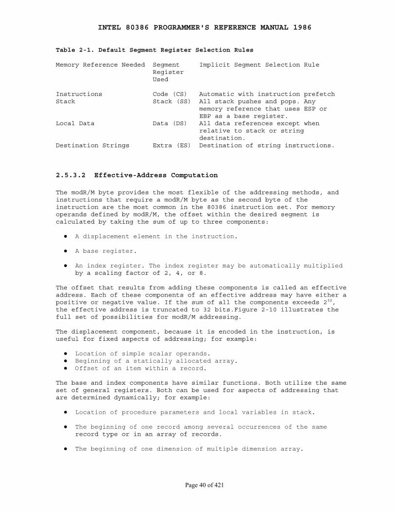
INTEL 80386 PROGRAMMER'S REFERENCE MANUAL 1986
Page 40 of 421
Table 2-1. Default Segment Register Selection Rules
Memory Reference Needed Segment Implicit Segment Selection Rule Register Used
Instructions Code (CS) Automatic with instruction prefetchStack Stack (SS) All stack pushes and pops. Any memory reference that uses ESP or EBP as a base register.Local Data Data (DS) All data references except when relative to stack or string destination.Destination Strings Extra (ES) Destination of string instructions.
2.5.3.2 Effective-Address Computation
The modR/M byte provides the most flexible of the addressing methods, andinstructions that require a modR/M byte as the second byte of theinstruction are the most common in the 80386 instruction set. For memoryoperands defined by modR/M, the offset within the desired segment iscalculated by taking the sum of up to three components:
● A displacement element in the instruction.
● A base register.
● An index register. The index register may be automatically multiplied by a scaling factor of 2, 4, or 8.
The offset that results from adding these components is called an effectiveaddress. Each of these components of an effective address may have either apositive or negative value. If the sum of all the components exceeds 232,the effective address is truncated to 32 bits.Figure 2-10 illustrates thefull set of possibilities for modR/M addressing.
The displacement component, because it is encoded in the instruction, isuseful for fixed aspects of addressing; for example:
● Location of simple scalar operands. ● Beginning of a statically allocated array. ● Offset of an item within a record.
The base and index components have similar functions. Both utilize the sameset of general registers. Both can be used for aspects of addressing thatare determined dynamically; for example:
● Location of procedure parameters and local variables in stack.
● The beginning of one record among several occurrences of the same record type or in an array of records.
● The beginning of one dimension of multiple dimension array.
INTEL 80386 PROGRAMMER'S REFERENCE MANUAL 1986
Page 41 of 421
● The beginning of a dynamically allocated array.
The uses of general registers as base or index components differ in thefollowing respects:
● ESP cannot be used as an index register.
● When ESP or EBP is used as the base register, the default segment is the one selected by SS. In all other cases the default segment is DS.
The scaling factor permits efficient indexing into an array in the commoncases when array elements are 2, 4, or 8 bytes wide. The shifting of theindex register is done by the processor at the time the address is evaluatedwith no performance loss. This eliminates the need for a separate shift ormultiply instruction.
The base, index, and displacement components may be used in anycombination; any of these components may be null. A scale factor can be usedonly when an index is also used. Each possible combination is useful fordata structures commonly used by programmers in high-level languages andassembly languages. Following are possible uses for some of the variouscombinations of address components.
DISPLACEMENT
The displacement alone indicates the offset of the operand. This combination is used to directly address a statically allocated scalar operand. An 8-bit, 16-bit, or 32-bit displacement can be used.
BASE
The offset of the operand is specified indirectly in one of the general registers, as for "based" variables.
BASE + DISPLACEMENT
A register and a displacement can be used together for two distinct purposes:
1. Index into static array when element size is not 2, 4, or 8 bytes. The displacement component encodes the offset of the beginning of the array. The register holds the results of a calculation to determine the offset of a specific element within the array.
2. Access item of a record. The displacement component locates an item within record. The base register selects one of several occurrences of record, thereby providing a compact encoding for this common function.
An important special case of this combination, is to access parameters in the procedure activation record in the stack. In this case, EBP is the best choice for the base register, because when EBP is used as a base register, the processor automatically uses the stack segment register (SS) to locate the operand, thereby providing a compact encoding for this common function.
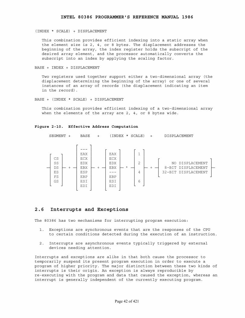
INTEL 80386 PROGRAMMER'S REFERENCE MANUAL 1986
Page 42 of 421
(INDEX * SCALE) + DISPLACEMENT
This combination provides efficient indexing into a static array when the element size is 2, 4, or 8 bytes. The displacement addresses the beginning of the array, the index register holds the subscript of the desired array element, and the processor automatically converts the subscript into an index by applying the scaling factor.
BASE + INDEX + DISPLACEMENT
Two registers used together support either a two-dimensional array (the displacement determining the beginning of the array) or one of several instances of an array of records (the displacement indicating an item in the record).
BASE + (INDEX * SCALE) + DISPLACEMENT
This combination provides efficient indexing of a two-dimensional array when the elements of the array are 2, 4, or 8 bytes wide.
Figure 2-10. Effective Address Computation
SEGMENT + BASE + (INDEX * SCALE) + DISPLACEMENT
┌ ┐ │ --- │ ┌ ┐ ┌ ┐ ┌ ┐ │ EAX │ │ EAX │ │ 1 │ │ CS │ │ ECX │ │ ECX │ │ │ ┌ ┐ │ SS │ │ EDX │ │ EDX │ │ 2 │ │ NO DISPLACEMENT │ ─┤ DS ├─ + ─┤ EBX ├─ + ─┤ EBX ├─ * ─┤ ├─ + ─┤ 8-BIT DISPLACEMENT ├─ │ ES │ │ ESP │ │ --- │ │ 4 │ │ 32-BIT DISPLACEMENT │ │ FS │ │ EBP │ │ EBP │ │ │ └ ┘ │ GS │ │ ESI │ │ ESI │ │ 6 │ └ ┘ │ EDI │ │ EDI │ └ ┘ └ ┘ └ ┘
2.6 Interrupts and Exceptions
The 80386 has two mechanisms for interrupting program execution:
1. Exceptions are synchronous events that are the responses of the CPU to certain conditions detected during the execution of an instruction.
2. Interrupts are asynchronous events typically triggered by external devices needing attention.
Interrupts and exceptions are alike in that both cause the processor totemporarily suspend its present program execution in order to execute aprogram of higher priority. The major distinction between these two kinds ofinterrupts is their origin. An exception is always reproducible byre-executing with the program and data that caused the exception, whereas aninterrupt is generally independent of the currently executing program.

INTEL 80386 PROGRAMMER'S REFERENCE MANUAL 1986
Page 43 of 421
Application programmers are not normally concerned with servicinginterrupts. More information on interrupts for systems programmers may befound in Chapter 9. Certain exceptions, however, are of interest toapplications programmers, and many operating systems give applicationsprograms the opportunity to service these exceptions. However, the operatingsystem itself defines the interface between the applications programs andthe exception mechanism of the 80386.
Table 2-2 highlights the exceptions that may be of interest to applicationsprogrammers.
● A divide error exception results when the instruction DIV or IDIV is executed with a zero denominator or when the quotient is too large for the destination operand. (Refer to Chapter 3 for a discussion of DIV and IDIV.)
● The debug exception may be reflected back to an applications program if it results from the trap flag (TF).
● A breakpoint exception results when the instruction INT 3 is executed. This instruction is used by some debuggers to stop program execution at specific points.
● An overflow exception results when the INTO instruction is executed and the OF (overflow) flag is set (after an arithmetic operation that set the OF flag). (Refer to Chapter 3 for a discussion of INTO).
● A bounds check exception results when the BOUND instruction is executed and the array index it checks falls outside the bounds of the array. (Refer to Chapter 3 for a discussion of the BOUND instruction.)
● Invalid opcodes may be used by some applications to extend the instruction set. In such a case, the invalid opcode exception presents an opportunity to emulate the opcode.
● The "coprocessor not available" exception occurs if the program contains instructions for a coprocessor, but no coprocessor is present in the system.
● A coprocessor error is generated when a coprocessor detects an illegal operation.
The instruction INT generates an interrupt whenever it is executed; theprocessor treats this interrupt as an exception. The effects of thisinterrupt (and the effects of all other exceptions) are determined byexception handler routines provided by the application program or as part ofthe systems software (provided by systems programmers). The INT instructionitself is discussed in Chapter 3. Refer to Chapter 9 for a more completedescription of exceptions.
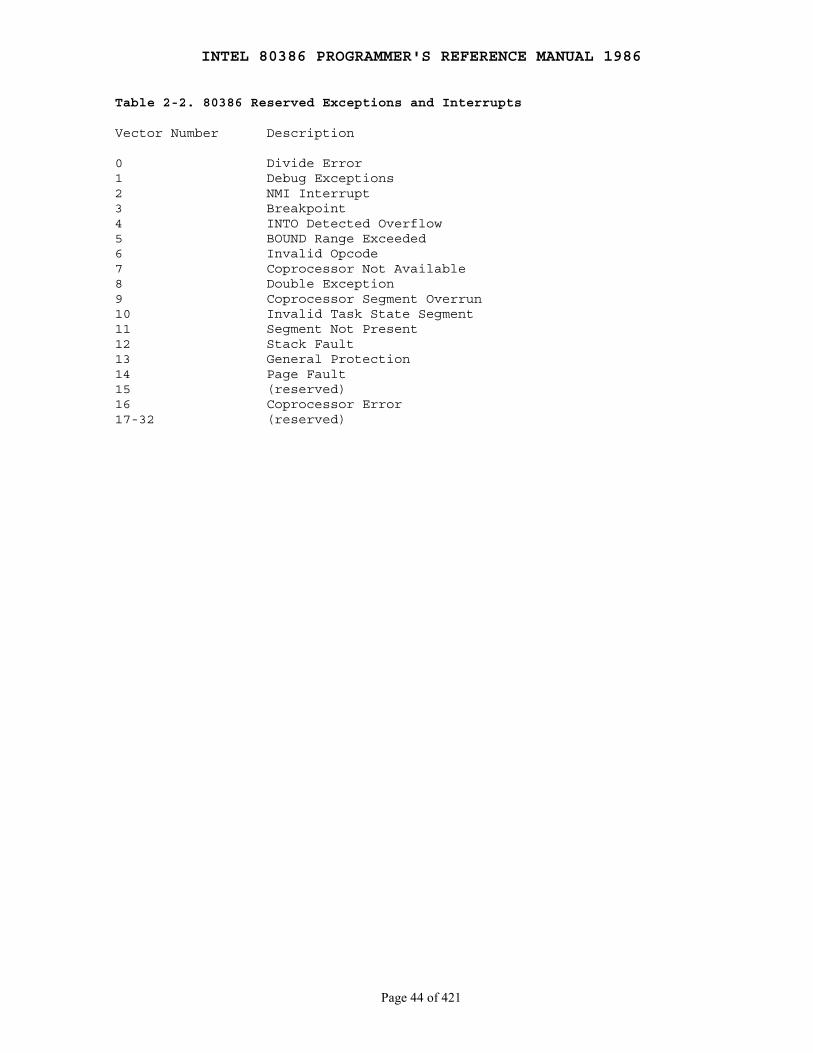
INTEL 80386 PROGRAMMER'S REFERENCE MANUAL 1986
Page 44 of 421
Table 2-2. 80386 Reserved Exceptions and Interrupts
Vector Number Description
0 Divide Error1 Debug Exceptions2 NMI Interrupt3 Breakpoint4 INTO Detected Overflow5 BOUND Range Exceeded6 Invalid Opcode7 Coprocessor Not Available8 Double Exception9 Coprocessor Segment Overrun10 Invalid Task State Segment11 Segment Not Present12 Stack Fault13 General Protection14 Page Fault15 (reserved)16 Coprocessor Error17-32 (reserved)
INTEL 80386 PROGRAMMER'S REFERENCE MANUAL 1986
Page 45 of 421
Chapter 3 Applications Instruction Set
────────────────────────────────────────────────────────────────────────────
This chapter presents an overview of the instructions which programmers canuse to write application software for the 80386 executing in protectedvirtual-address mode. The instructions are grouped by categories of relatedfunctions.
The instructions not discussed in this chapter are those that are normallyused only by operating-system programmers. Part II describes the operationof these instructions.
The descriptions in this chapter assume that the 80386 is operating inprotected mode with 32-bit addressing in effect; however, all instructionsdiscussed are also available when 16-bit addressing is in effect inprotected mode, real mode, or virtual 8086 mode. For any differences ofoperation that exist in the various modes, refer to Chapter 13,Chapter 14, or Chapter 15.
The instruction dictionary in Chapter 17 contains more detaileddescriptions of all instructions, including encoding, operation, timing,effect on flags, and exceptions.
3.1 Data Movement Instructions
These instructions provide convenient methods for moving bytes, words, ordoublewords of data between memory and the registers of the basearchitecture. They fall into the following classes:
1. General-purpose data movement instructions. 2. Stack manipulation instructions. 3. Type-conversion instructions.
3.1.1 General-Purpose Data Movement Instructions
MOV (Move) transfers a byte, word, or doubleword from the source operand tothe destination operand. The MOV instruction is useful for transferring dataalong any of these paths. There are also variants of MOV that operate onsegment registers. These are covered in a later section of this chapter.:
● To a register from memory ● To memory from a register ● Between general registers ● Immediate data to a register ● Immediate data to a memory
The MOV instruction cannot move from memory to memory or from segmentregister to segment register are not allowed. Memory-to-memory moves can beperformed, however, by the string move instruction MOVS.

INTEL 80386 PROGRAMMER'S REFERENCE MANUAL 1986
Page 46 of 421
XCHG (Exchange) swaps the contents of two operands. This instruction takesthe place of three MOV instructions. It does not require a temporarylocation to save the contents of one operand while load the other is beingloaded. XCHG is especially useful for implementing semaphores or similardata structures for process synchronization.
The XCHG instruction can swap two byte operands, two word operands, or twodoubleword operands. The operands for the XCHG instruction may be tworegister operands, or a register operand with a memory operand. When usedwith a memory operand, XCHG automatically activates the LOCK signal. (Referto Chapter 11 for more information on the bus lock.)
3.1.2 Stack Manipulation Instructions
PUSH (Push) decrements the stack pointer (ESP), then transfers the sourceoperand to the top of stack indicated by ESP (see Figure 3-1). PUSH isoften used to place parameters on the stack before calling a procedure; itis also the basic means of storing temporary variables on the stack. ThePUSH instruction operates on memory operands, immediate operands, andregister operands (including segment registers).
PUSHA (Push All Registers) saves the contents of the eight generalregisters on the stack (see Figure 3-2). This instruction simplifiesprocedure calls by reducing the number of instructions required to retainthe contents of the general registers for use in a procedure. The processorpushes the general registers on the stack in the following order: EAX, ECX,EDX, EBX, the initial value of ESP before EAX was pushed, EBP, ESI, andEDI. PUSHA is complemented by the POPA instruction.
POP (Pop) transfers the word or doubleword at the current top of stack(indicated by ESP) to the destination operand, and then increments ESP topoint to the new top of stack. See Figure 3-3. POP moves information fromthe stack to a general register, or to memoryThere are also a variant of POP that operates on segment registers. Thisis covered in a later section of this chapter..
POPA (Pop All Registers) restores the registers saved on the stack byPUSHA, except that it ignores the saved value of ESP. See Figure 3-4.
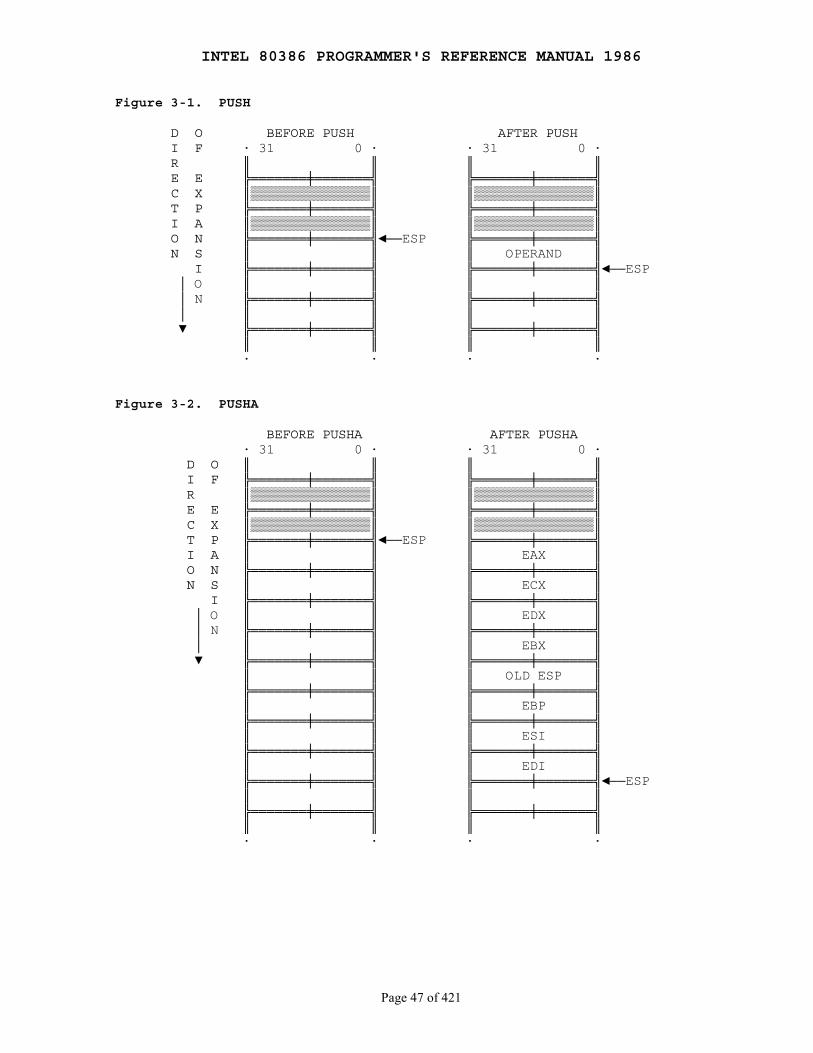
INTEL 80386 PROGRAMMER'S REFERENCE MANUAL 1986
Page 47 of 421
Figure 3-1. PUSH
D O BEFORE PUSH AFTER PUSH I F · 31 0 · · 31 0 · R ║ ║ ║ ║ E E ╠═══════╪═══════╣ ╠═══════╪═══════╣ C X ║▒▒▒▒▒▒▒▒▒▒▒▒▒▒▒║ ║▒▒▒▒▒▒▒▒▒▒▒▒▒▒▒║ T P ╠═══════╪═══════╣ ╠═══════╪═══════╣ I A ║▒▒▒▒▒▒▒▒▒▒▒▒▒▒▒║ ║▒▒▒▒▒▒▒▒▒▒▒▒▒▒▒║ O N ╠═══════╪═══════╣◄──ESP ╠═══════╪═══════╣ N S ║ ║ ║ OPERAND ║ I ╠═══════╪═══════╣ ╠═══════╪═══════╣◄──ESP │ O ║ ║ ║ ║ │ N ╠═══════╪═══════╣ ╠═══════╪═══════╣ │ ║ ║ ║ ║ ▼ ╠═══════╪═══════╣ ╠═══════╪═══════╣ ║ ║ ║ ║ · · · ·
Figure 3-2. PUSHA
BEFORE PUSHA AFTER PUSHA · 31 0 · · 31 0 · D O ║ ║ ║ ║ I F ╠═══════╪═══════╣ ╠═══════╪═══════╣ R ║▒▒▒▒▒▒▒▒▒▒▒▒▒▒▒║ ║▒▒▒▒▒▒▒▒▒▒▒▒▒▒▒║ E E ╠═══════╪═══════╣ ╠═══════╪═══════╣ C X ║▒▒▒▒▒▒▒▒▒▒▒▒▒▒▒║ ║▒▒▒▒▒▒▒▒▒▒▒▒▒▒▒║ T P ╠═══════╪═══════╣◄──ESP ╠═══════╪═══════╣ I A ║ ║ ║ EAX ║ O N ╠═══════╪═══════╣ ╠═══════╪═══════╣ N S ║ ║ ║ ECX ║ I ╠═══════╪═══════╣ ╠═══════╪═══════╣ │ O ║ ║ ║ EDX ║ │ N ╠═══════╪═══════╣ ╠═══════╪═══════╣ │ ║ ║ ║ EBX ║ ▼ ╠═══════╪═══════╣ ╠═══════╪═══════╣ ║ ║ ║ OLD ESP ║ ╠═══════╪═══════╣ ╠═══════╪═══════╣ ║ ║ ║ EBP ║ ╠═══════╪═══════╣ ╠═══════╪═══════╣ ║ ║ ║ ESI ║ ╠═══════╪═══════╣ ╠═══════╪═══════╣ ║ ║ ║ EDI ║ ╠═══════╪═══════╣ ╠═══════╪═══════╣◄──ESP ║ ║ ║ ║ ╠═══════╪═══════╣ ╠═══════╪═══════╣ ║ ║ ║ ║ · · · ·
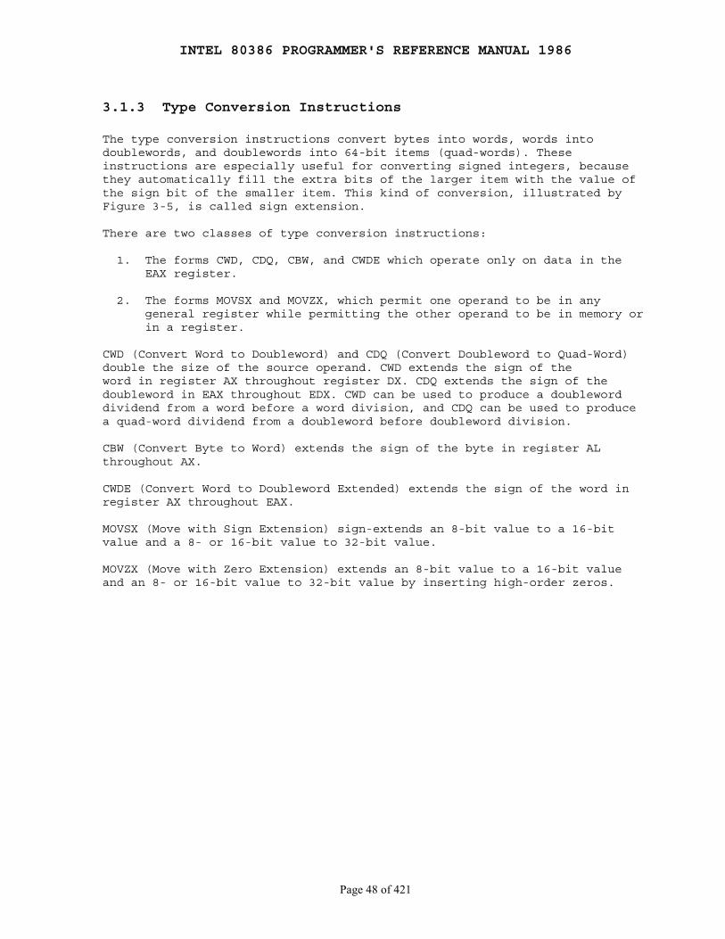
INTEL 80386 PROGRAMMER'S REFERENCE MANUAL 1986
Page 48 of 421
3.1.3 Type Conversion Instructions
The type conversion instructions convert bytes into words, words intodoublewords, and doublewords into 64-bit items (quad-words). Theseinstructions are especially useful for converting signed integers, becausethey automatically fill the extra bits of the larger item with the value ofthe sign bit of the smaller item. This kind of conversion, illustrated byFigure 3-5, is called sign extension.
There are two classes of type conversion instructions:
1. The forms CWD, CDQ, CBW, and CWDE which operate only on data in the EAX register.
2. The forms MOVSX and MOVZX, which permit one operand to be in any general register while permitting the other operand to be in memory or in a register.
CWD (Convert Word to Doubleword) and CDQ (Convert Doubleword to Quad-Word)double the size of the source operand. CWD extends the sign of theword in register AX throughout register DX. CDQ extends the sign of thedoubleword in EAX throughout EDX. CWD can be used to produce a doubleworddividend from a word before a word division, and CDQ can be used to producea quad-word dividend from a doubleword before doubleword division.
CBW (Convert Byte to Word) extends the sign of the byte in register ALthroughout AX.
CWDE (Convert Word to Doubleword Extended) extends the sign of the word inregister AX throughout EAX.
MOVSX (Move with Sign Extension) sign-extends an 8-bit value to a 16-bitvalue and a 8- or 16-bit value to 32-bit value.
MOVZX (Move with Zero Extension) extends an 8-bit value to a 16-bit valueand an 8- or 16-bit value to 32-bit value by inserting high-order zeros.
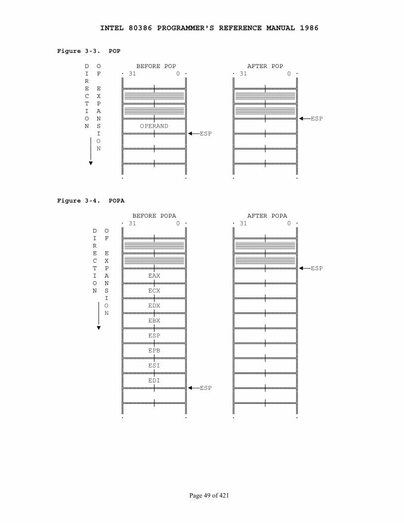
INTEL 80386 PROGRAMMER'S REFERENCE MANUAL 1986
Page 49 of 421
Figure 3-3. POP
D O BEFORE POP AFTER POP I F · 31 0 · · 31 0 · R ║ ║ ║ ║ E E ╠═══════╪═══════╣ ╠═══════╪═══════╣ C X ║▒▒▒▒▒▒▒▒▒▒▒▒▒▒▒║ ║▒▒▒▒▒▒▒▒▒▒▒▒▒▒▒║ T P ╠═══════╪═══════╣ ╠═══════╪═══════╣ I A ║▒▒▒▒▒▒▒▒▒▒▒▒▒▒▒║ ║▒▒▒▒▒▒▒▒▒▒▒▒▒▒▒║ O N ╠═══════╪═══════╣ ╠═══════╪═══════╣◄──ESP N S ║ OPERAND ║ ║ ║ I ╠═══════╪═══════╣◄──ESP ╠═══════╪═══════╣ │ O ║ ║ ║ ║ │ N ╠═══════╪═══════╣ ╠═══════╪═══════╣ │ ║ ║ ║ ║ ▼ ╠═══════╪═══════╣ ╠═══════╪═══════╣ ║ ║ ║ ║ · · · ·
Figure 3-4. POPA
BEFORE POPA AFTER POPA · 31 0 · · 31 0 · D O ║ ║ ║ ║ I F ╠═══════╪═══════╣ ╠═══════╪═══════╣ R ║▒▒▒▒▒▒▒▒▒▒▒▒▒▒▒║ ║▒▒▒▒▒▒▒▒▒▒▒▒▒▒▒║ E E ╠═══════╪═══════╣ ╠═══════╪═══════╣ C X ║▒▒▒▒▒▒▒▒▒▒▒▒▒▒▒║ ║▒▒▒▒▒▒▒▒▒▒▒▒▒▒▒║ T P ╠═══════╪═══════╣ ╠═══════╪═══════╣◄──ESP I A ║ EAX ║ ║ ║ O N ╠═══════╪═══════╣ ╠═══════╪═══════╣ N S ║ ECX ║ ║ ║ I ╠═══════╪═══════╣ ╠═══════╪═══════╣ │ O ║ EDX ║ ║ ║ │ N ╠═══════╪═══════╣ ╠═══════╪═══════╣ │ ║ EBX ║ ║ ║ ▼ ╠═══════╪═══════╣ ╠═══════╪═══════╣ ║ ESP ║ ║ ║ ╠═══════╪═══════╣ ╠═══════╪═══════╣ ║ EPB ║ ║ ║ ╠═══════╪═══════╣ ╠═══════╪═══════╣ ║ ESI ║ ║ ║ ╠═══════╪═══════╣ ╠═══════╪═══════╣ ║ EDI ║ ║ ║ ╠═══════╪═══════╣◄──ESP ╠═══════╪═══════╣ ║ ║ ║ ║ ╠═══════╪═══════╣ ╠═══════╪═══════╣ ║ ║ ║ ║ · · · ·
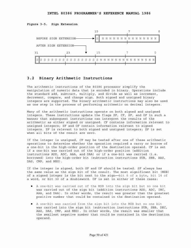
INTEL 80386 PROGRAMMER'S REFERENCE MANUAL 1986
Page 50 of 421
Figure 3-5. Sign Extension
15 7 0 ╔═╦══════════════╪════════════════╗ BEFORE SIGN EXTENSION─────────►║S║ N N N N N N N N N N N N N N N ║ ╚═╩══════════════╪════════════════╝ AFTER SIGN EXTENSION──────┐ │ 31 23 ▼ 15 7 0 ╔═╦═════════════╪═══════════════╪═══════════════╪═══════════════╗ ║S║S S S S S S S S S S S S S S S S N N N N N N N N N N N N N N N║ ╚═╩═════════════╪═══════════════╪═══════════════╪═══════════════╝
3.2 Binary Arithmetic Instructions
The arithmetic instructions of the 80386 processor simplify themanipulation of numeric data that is encoded in binary. Operations includethe standard add, subtract, multiply, and divide as well as increment,decrement, compare, and change sign. Both signed and unsigned binaryintegers are supported. The binary arithmetic instructions may also be usedas one step in the process of performing arithmetic on decimal integers.
Many of the arithmetic instructions operate on both signed and unsignedintegers. These instructions update the flags ZF, CF, SF, and OF in such amanner that subsequent instructions can interpret the results of thearithmetic as either signed or unsigned. CF contains information relevant tounsigned integers; SF and OF contain information relevant to signedintegers. ZF is relevant to both signed and unsigned integers; ZF is setwhen all bits of the result are zero.
If the integer is unsigned, CF may be tested after one of these arithmeticoperations to determine whether the operation required a carry or borrow ofa one-bit in the high-order position of the destination operand. CF is setif a one-bit was carried out of the high-order position (additioninstructions ADD, ADC, AAA, and DAA) or if a one-bit was carried (i.e.borrowed) into the high-order bit (subtraction instructions SUB, SBB, AAS,DAS, CMP, and NEG).
If the integer is signed, both SF and OF should be tested. SF always hasthe same value as the sign bit of the result. The most significant bit (MSB)of a signed integer is the bit next to the sign──bit 6 of a byte, bit 14 ofa word, or bit 30 of a doubleword. OF is set in either of these cases:
● A one-bit was carried out of the MSB into the sign bit but no one bit was carried out of the sign bit (addition instructions ADD, ADC, INC, AAA, and DAA). In other words, the result was greater than the greatest positive number that could be contained in the destination operand.
● A one-bit was carried from the sign bit into the MSB but no one bit was carried into the sign bit (subtraction instructions SUB, SBB, DEC, AAS, DAS, CMP, and NEG). In other words, the result was smaller that the smallest negative number that could be contained in the destination operand.
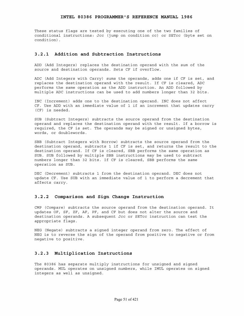
INTEL 80386 PROGRAMMER'S REFERENCE MANUAL 1986
Page 51 of 421
These status flags are tested by executing one of the two families ofconditional instructions: Jcc (jump on condition cc) or SETcc (byte set oncondition).
3.2.1 Addition and Subtraction Instructions
ADD (Add Integers) replaces the destination operand with the sum of thesource and destination operands. Sets CF if overflow.
ADC (Add Integers with Carry) sums the operands, adds one if CF is set, andreplaces the destination operand with the result. If CF is cleared, ADCperforms the same operation as the ADD instruction. An ADD followed bymultiple ADC instructions can be used to add numbers longer than 32 bits.
INC (Increment) adds one to the destination operand. INC does not affectCF. Use ADD with an immediate value of 1 if an increment that updates carry(CF) is needed.
SUB (Subtract Integers) subtracts the source operand from the destinationoperand and replaces the destination operand with the result. If a borrow isrequired, the CF is set. The operands may be signed or unsigned bytes,words, or doublewords.
SBB (Subtract Integers with Borrow) subtracts the source operand from thedestination operand, subtracts 1 if CF is set, and returns the result to thedestination operand. If CF is cleared, SBB performs the same operation asSUB. SUB followed by multiple SBB instructions may be used to subtractnumbers longer than 32 bits. If CF is cleared, SBB performs the sameoperation as SUB.
DEC (Decrement) subtracts 1 from the destination operand. DEC does notupdate CF. Use SUB with an immediate value of 1 to perform a decrement thataffects carry.
3.2.2 Comparison and Sign Change Instruction
CMP (Compare) subtracts the source operand from the destination operand. Itupdates OF, SF, ZF, AF, PF, and CF but does not alter the source anddestination operands. A subsequent Jcc or SETcc instruction can test theappropriate flags.
NEG (Negate) subtracts a signed integer operand from zero. The effect ofNEG is to reverse the sign of the operand from positive to negative or fromnegative to positive.
3.2.3 Multiplication Instructions
The 80386 has separate multiply instructions for unsigned and signedoperands. MUL operates on unsigned numbers, while IMUL operates on signedintegers as well as unsigned.

INTEL 80386 PROGRAMMER'S REFERENCE MANUAL 1986
Page 52 of 421
MUL (Unsigned Integer Multiply) performs an unsigned multiplication of thesource operand and the accumulator. If the source is a byte, the processormultiplies it by the contents of AL and returns the double-length result toAH and AL. If the source operand is a word, the processor multiplies it bythe contents of AX and returns the double-length result to DX and AX. If thesource operand is a doubleword, the processor multiplies it by the contentsof EAX and returns the 64-bit result in EDX and EAX. MUL sets CF and OFwhen the upper half of the result is nonzero; otherwise, they are cleared.
IMUL (Signed Integer Multiply) performs a signed multiplication operation.IMUL has three variations:
1. A one-operand form. The operand may be a byte, word, or doubleword located in memory or in a general register. This instruction uses EAX and EDX as implicit operands in the same way as the MUL instruction.
2. A two-operand form. One of the source operands may be in any general register while the other may be either in memory or in a general register. The product replaces the general-register operand.
3. A three-operand form; two are source and one is the destination operand. One of the source operands is an immediate value stored in the instruction; the second may be in memory or in any general register. The product may be stored in any general register. The immediate operand is treated as signed. If the immediate operand is a byte, the processor automatically sign-extends it to the size of the second operand before performing the multiplication.
The three forms are similar in most respects:
● The length of the product is calculated to twice the length of the operands.
● The CF and OF flags are set when significant bits are carried into the high-order half of the result. CF and OF are cleared when the high-order half of the result is the sign-extension of the low-order half.
However, forms 2 and 3 differ in that the product is truncated to thelength of the operands before it is stored in the destination register.Because of this truncation, OF should be tested to ensure that nosignificant bits are lost. (For ways to test OF, refer to the INTO and PUSHFinstructions.)
Forms 2 and 3 of IMUL may also be used with unsigned operands because,whether the operands are signed or unsigned, the low-order half of theproduct is the same.
3.2.4 Division Instructions
The 80386 has separate division instructions for unsigned and signedoperands. DIV operates on unsigned numbers, while IDIV operates on signedintegers as well as unsigned. In either case, an exception (interrupt zero)occurs if the divisor is zero or if the quotient is too large for AL, AX, orEAX.
INTEL 80386 PROGRAMMER'S REFERENCE MANUAL 1986
Page 53 of 421
DIV (Unsigned Integer Divide) performs an unsigned division of theaccumulator by the source operand. The dividend (the accumulator) is twicethe size of the divisor (the source operand); the quotient and remainderhave the same size as the divisor, as the following table shows.
Size of Source Operand (divisor) Dividend Quotient Remainder
Byte AX AL AHWord DX:AX AX DXDoubleword EDX:EAX EAX EDX
Non-integral quotients are truncated to integers toward 0. The remainder isalways less than the divisor. For unsigned byte division, the largestquotient is 255. For unsigned word division, the largest quotient is 65,535.For unsigned doubleword division the largest quotient is 232-1.
IDIV (Signed Integer Divide) performs a signed division of the accumulatorby the source operand. IDIV uses the same registers as the DIV instruction.
For signed byte division, the maximum positive quotient is +127, and theminimum negative quotient is -128. For signed word division, the maximumpositive quotient is +32,767, and the minimum negative quotient is -32,768.For signed doubleword division the maximum positive quotient is 231-1,the minimum negative quotient is -231. Non-integral results are truncatedtowards 0. The remainder always has the same sign as the dividend and isless than the divisor in magnitude.
3.3 Decimal Arithmetic Instructions
Decimal arithmetic is performed by combining the binary arithmeticinstructions (already discussed in the prior section) with the decimalarithmetic instructions. The decimal arithmetic instructions are used in oneof the following ways:
● To adjust the results of a previous binary arithmetic operation to produce a valid packed or unpacked decimal result.
● To adjust the inputs to a subsequent binary arithmetic operation so that the operation will produce a valid packed or unpacked decimal result.
These instructions operate only on the AL or AH registers. Most utilize theAF flag.
3.3.1 Packed BCD Adjustment Instructions
DAA (Decimal Adjust after Addition) adjusts the result of adding two validpacked decimal operands in AL. DAA must always follow the addition of twopairs of packed decimal numbers (one digit in each half-byte) to obtain apair of valid packed decimal digits as results. The carry flag is set ifcarry was needed.
INTEL 80386 PROGRAMMER'S REFERENCE MANUAL 1986
Page 54 of 421
DAS (Decimal Adjust after Subtraction) adjusts the result of subtractingtwo valid packed decimal operands in AL. DAS must always follow thesubtraction of one pair of packed decimal numbers (one digit in each half-byte) from another to obtain a pair of valid packed decimal digits asresults. The carry flag is set if a borrow was needed.
3.3.2 Unpacked BCD Adjustment Instructions
AAA (ASCII Adjust after Addition) changes the contents of register AL to avalid unpacked decimal number, and zeros the top 4 bits. AAA must alwaysfollow the addition of two unpacked decimal operands in AL. The carry flagis set and AH is incremented if a carry is necessary.
AAS (ASCII Adjust after Subtraction) changes the contents of register AL toa valid unpacked decimal number, and zeros the top 4 bits. AAS must alwaysfollow the subtraction of one unpacked decimal operand from another in AL.The carry flag is set and AH decremented if a borrow is necessary.
AAM (ASCII Adjust after Multiplication) corrects the result of amultiplication of two valid unpacked decimal numbers. AAM must always followthe multiplication of two decimal numbers to produce a valid decimal result.The high order digit is left in AH, the low order digit in AL.
AAD (ASCII Adjust before Division) modifies the numerator in AH and AL toprepare for the division of two valid unpacked decimal operands so that thequotient produced by the division will be a valid unpacked decimal number.AH should contain the high-order digit and AL the low-order digit. Thisinstruction adjusts the value and places the result in AL. AH will containzero.
3.4 Logical Instructions
The group of logical instructions includes:
● The Boolean operation instructions ● Bit test and modify instructions ● Bit scan instructions ● Rotate and shift instructions ● Byte set on condition
3.4.1 Boolean Operation Instructions
The logical operations are AND, OR, XOR, and NOT.
NOT (Not) inverts the bits in the specified operand to form a one'scomplement of the operand. The NOT instruction is a unary operation thatuses a single operand in a register or memory. NOT has no effect on theflags.

INTEL 80386 PROGRAMMER'S REFERENCE MANUAL 1986
Page 55 of 421
The AND, OR, and XOR instructions perform the standard logical operations"and", "(inclusive) or", and "exclusive or". These instructions can use thefollowing combinations of operands:
● Two register operands
● A general register operand with a memory operand
● An immediate operand with either a general register operand or a memory operand.
AND, OR, and XOR clear OF and CF, leave AF undefined, and update SF, ZF,and PF.
3.4.2 Bit Test and Modify Instructions
This group of instructions operates on a single bit which can be in memoryor in a general register. The location of the bit is specified as an offsetfrom the low-order end of the operand. The value of the offset either may begiven by an immediate byte in the instruction or may be contained in ageneral register.
These instructions first assign the value of the selected bit to CF, thecarry flag. Then a new value is assigned to the selected bit, as determinedby the operation. OF, SF, ZF, AF, PF are left in an undefined state. Table3-1 defines these instructions.
Table 3-1. Bit Test and Modify Instructions
Instruction Effect on CF Effect on Selected Bit
Bit (Bit Test) CF ← BIT (none)BTS (Bit Test and Set) CF ← BIT BIT ← 1BTR (Bit Test and Reset) CF ← BIT BIT ← 0BTC (Bit Test and Complement) CF ← BIT BIT ← NOT(BIT)
3.4.3 Bit Scan Instructions
These instructions scan a word or doubleword for a one-bit and store theindex of the first set bit into a register. The bit string being scannedmay be either in a register or in memory. The ZF flag is set if the entireword is zero (no set bits are found); ZF is cleared if a one-bit is found.If no set bit is found, the value of the destination register is undefined.
BSF (Bit Scan Forward) scans from low-order to high-order (starting frombit index zero).
BSR (Bit Scan Reverse) scans from high-order to low-order (starting frombit index 15 of a word or index 31 of a doubleword).
INTEL 80386 PROGRAMMER'S REFERENCE MANUAL 1986
Page 56 of 421
3.4.4 Shift and Rotate Instructions
The shift and rotate instructions reposition the bits within the specifiedoperand.
These instructions fall into the following classes:
● Shift instructions ● Double shift instructions ● Rotate instructions
3.4.4.1 Shift Instructions
The bits in bytes, words, and doublewords may be shifted arithmetically orlogically. Depending on the value of a specified count, bits can be shiftedup to 31 places.
A shift instruction can specify the count in one of three ways. One form ofshift instruction implicitly specifies the count as a single shift. Thesecond form specifies the count as an immediate value. The third formspecifies the count as the value contained in CL. This last form allows theshift count to be a variable that the program supplies during execution.Only the low order 5 bits of CL are used.
CF always contains the value of the last bit shifted out of the destinationoperand. In a single-bit shift, OF is set if the value of the high-order(sign) bit was changed by the operation. Otherwise, OF is cleared. Followinga multibit shift, however, the content of OF is always undefined.
The shift instructions provide a convenient way to accomplish division ormultiplication by binary power. Note however that division of signed numbersby shifting right is not the same kind of division performed by the IDIVinstruction.
SAL (Shift Arithmetic Left) shifts the destination byte, word, ordoubleword operand left by one or by the number of bits specified in thecount operand (an immediate value or the value contained in CL). Theprocessor shifts zeros in from the right (low-order) side of the operand asbits exit from the left (high-order) side. See Figure 3-6.
SHL (Shift Logical Left) is a synonym for SAL (refer to SAL).
SHR (Shift Logical Right) shifts the destination byte, word, or doublewordoperand right by one or by the number of bits specified in the count operand(an immediate value or the value contained in CL). The processor shiftszeros in from the left side of the operand as bits exit from the right side.See Figure 3-7.
SAR (Shift Arithmetic Right) shifts the destination byte, word, ordoubleword operand to the right by one or by the number of bits specified inthe count operand (an immediate value or the value contained in CL). Theprocessor preserves the sign of the operand by shifting in zeros on the left(high-order) side if the value is positive or by shifting by ones if thevalue is negative. See Figure 3-8.
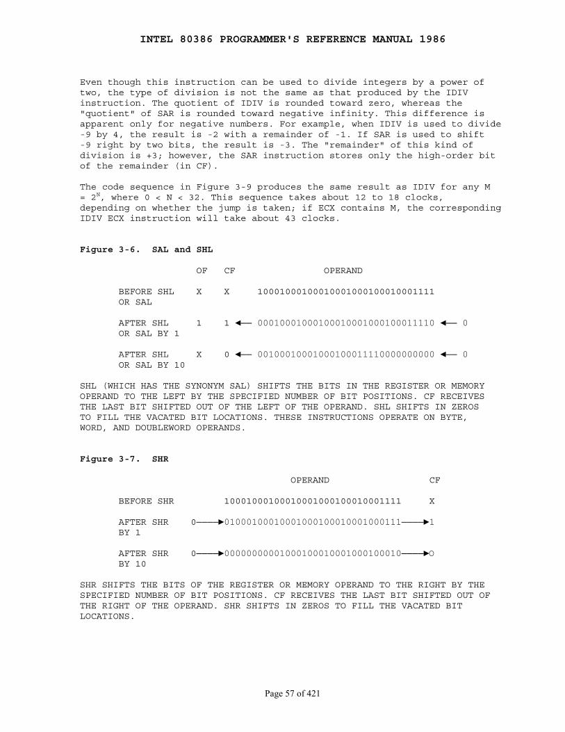
INTEL 80386 PROGRAMMER'S REFERENCE MANUAL 1986
Page 57 of 421
Even though this instruction can be used to divide integers by a power oftwo, the type of division is not the same as that produced by the IDIVinstruction. The quotient of IDIV is rounded toward zero, whereas the"quotient" of SAR is rounded toward negative infinity. This difference isapparent only for negative numbers. For example, when IDIV is used to divide-9 by 4, the result is -2 with a remainder of -1. If SAR is used to shift-9 right by two bits, the result is -3. The "remainder" of this kind ofdivision is +3; however, the SAR instruction stores only the high-order bitof the remainder (in CF).
The code sequence in Figure 3-9 produces the same result as IDIV for any M= 2N, where 0 < N < 32. This sequence takes about 12 to 18 clocks,depending on whether the jump is taken; if ECX contains M, the correspondingIDIV ECX instruction will take about 43 clocks.
Figure 3-6. SAL and SHL
OF CF OPERAND
BEFORE SHL X X 10001000100010001000100010001111 OR SAL
AFTER SHL 1 1 ◄── 00010001000100010001000100011110 ◄── 0 OR SAL BY 1
AFTER SHL X 0 ◄── 00100010001000100011110000000000 ◄── 0 OR SAL BY 10
SHL (WHICH HAS THE SYNONYM SAL) SHIFTS THE BITS IN THE REGISTER OR MEMORYOPERAND TO THE LEFT BY THE SPECIFIED NUMBER OF BIT POSITIONS. CF RECEIVESTHE LAST BIT SHIFTED OUT OF THE LEFT OF THE OPERAND. SHL SHIFTS IN ZEROSTO FILL THE VACATED BIT LOCATIONS. THESE INSTRUCTIONS OPERATE ON BYTE,WORD, AND DOUBLEWORD OPERANDS.
Figure 3-7. SHR
OPERAND CF
BEFORE SHR 10001000100010001000100010001111 X
AFTER SHR 0────►01000100010001000100010001000111────►1 BY 1
AFTER SHR 0────►00000000001000100010001000100010────►O BY 10
SHR SHIFTS THE BITS OF THE REGISTER OR MEMORY OPERAND TO THE RIGHT BY THESPECIFIED NUMBER OF BIT POSITIONS. CF RECEIVES THE LAST BIT SHIFTED OUT OFTHE RIGHT OF THE OPERAND. SHR SHIFTS IN ZEROS TO FILL THE VACATED BITLOCATIONS.
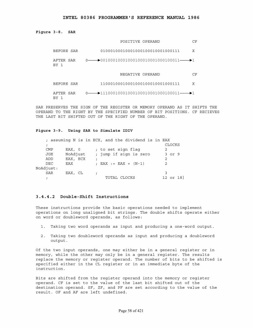
INTEL 80386 PROGRAMMER'S REFERENCE MANUAL 1986
Page 58 of 421
Figure 3-8. SAR
POSITIVE OPERAND CF
BEFORE SAR 01000100010001000100010001000111 X
AFTER SAR 0────►00100010001000100010001000100011────►1 BY 1
NEGATIVE OPERAND CF
BEFORE SAR 11000100010001000100010001000111 X
AFTER SAR 0────►11100010001000100010001000100011────►1 BY 1
SAR PRESERVES THE SIGN OF THE REGISTER OR MEMORY OPERAND AS IT SHIFTS THEOPERAND TO THE RIGHT BY THE SPECIFIED NUMBER OF BIT POSITIONS. CF RECIEVESTHE LAST BIT SHIFTED OUT OF THE RIGHT OF THE OPERAND.
Figure 3-9. Using SAR to Simulate IDIV
; assuming N is in ECX, and the dividend is in EAX ; CLOCKS CMP EAX, 0 ; to set sign flag 2 JGE NoAdjust ; jump if sign is zero 3 or 9 ADD EAX, ECX ; 2 DEC EAX ; EAX := EAX + (N-1) 2NoAdjust: SAR EAX, CL ; 3 ; TOTAL CLOCKS 12 or 18]
3.4.4.2 Double-Shift Instructions
These instructions provide the basic operations needed to implementoperations on long unaligned bit strings. The double shifts operate eitheron word or doubleword operands, as follows:
1. Taking two word operands as input and producing a one-word output.
2. Taking two doubleword operands as input and producing a doubleword output.
Of the two input operands, one may either be in a general register or inmemory, while the other may only be in a general register. The resultsreplace the memory or register operand. The number of bits to be shifted isspecified either in the CL register or in an immediate byte of theinstruction.
Bits are shifted from the register operand into the memory or registeroperand. CF is set to the value of the last bit shifted out of thedestination operand. SF, ZF, and PF are set according to the value of theresult. OF and AF are left undefined.
INTEL 80386 PROGRAMMER'S REFERENCE MANUAL 1986
Page 59 of 421
SHLD (Shift Left Double) shifts bits of the R/M field to the left, whileshifting high-order bits from the Reg field into the R/M field on the right(see Figure 3-10). The result is stored back into the R/M operand. The Regfield is not modified.
SHRD (Shift Right Double) shifts bits of the R/M field to the right, whileshifting low-order bits from the Reg field into the R/M field on the left(see Figure 3-11). The result is stored back into the R/M operand. The Regfield is not modified.
3.4.4.3 Rotate Instructions
Rotate instructions allow bits in bytes, words, and doublewords to berotated. Bits rotated out of an operand are not lost as in a shift, but are"circled" back into the other "end" of the operand.
Rotates affect only the carry and overflow flags. CF may act as anextension of the operand in two of the rotate instructions, allowing a bitto be isolated and then tested by a conditional jump instruction (JC orJNC). CF always contains the value of the last bit rotated out, even if theinstruction does not use this bit as an extension of the rotated operand.
In single-bit rotates, OF is set if the operation changes the high-order(sign) bit of the destination operand. If the sign bit retains its originalvalue, OF is cleared. On multibit rotates, the value of OF is alwaysundefined.
ROL (Rotate Left) rotates the byte, word, or doubleword destination operandleft by one or by the number of bits specified in the count operand (animmediate value or the value contained in CL). For each rotation specified,the high-order bit that exits from the left of the operand returns at theright to become the new low-order bit of the operand. See Figure 3-12.
ROR (Rotate Right) rotates the byte, word, or doubleword destinationoperand right by one or by the number of bits specified in the count operand(an immediate value or the value contained in CL). For each rotationspecified, the low-order bit that exits from the right of the operandreturns at the left to become the new high-order bit of the operand.See Figure 3-13.
RCL (Rotate Through Carry Left) rotates bits in the byte, word, ordoubleword destination operand left by one or by the number of bitsspecified in the count operand (an immediate value or the value contained inCL).
This instruction differs from ROL in that it treats CF as a high-orderone-bit extension of the destination operand. Each high-order bit that exitsfrom the left side of the operand moves to CF before it returns to theoperand as the low-order bit on the next rotation cycle. See Figure 3-14.
RCR (Rotate Through Carry Right) rotates bits in the byte, word, ordoubleword destination operand right by one or by the number of bitsspecified in the count operand (an immediate value or the value contained inCL).
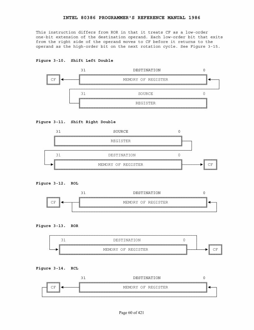
INTEL 80386 PROGRAMMER'S REFERENCE MANUAL 1986
Page 60 of 421
This instruction differs from ROR in that it treats CF as a low-orderone-bit extension of the destination operand. Each low-order bit that exitsfrom the right side of the operand moves to CF before it returns to theoperand as the high-order bit on the next rotation cycle. See Figure 3-15.
Figure 3-10. Shift Left Double
31 DESTINATION 0 ╔════╗ ╔══════════════════════════════════════════════════╗ ║ CF ║◄──────╢ MEMORY OF REGISTER ║◄───┐ ╚════╝ ╚══════════════════════════════════════════════════╝ │ ┌───────────────────────────────────────────────────────────┘ │ 31 SOURCE 0 │ ╔══════════════════════════════════════════════════╗ └───╢ REGISTER ║ ╚══════════════════════════════════════════════════╝
Figure 3-11. Shift Right Double
31 SOURCE 0 ╔══════════════════════════════════════════════════╗ ║ REGISTER ╟───┐ ╚══════════════════════════════════════════════════╝ │ ┌──────────────────────────────────────────────────────────┘ │ 31 DESTINATION 0 │ ╔══════════════════════════════════════════════════╗ ╔════╗ └──►║ MEMORY OF REGISTER ╟───────►║ CF ║ ╚══════════════════════════════════════════════════╝ ╚════╝
Figure 3-12. ROL
31 DESTINATION 0 ╔════╗ ╔══════════════════════════════════════════════════╗ ║ CF ║◄───┬──╢ MEMORY OF REGISTER ║◄──┐ ╚════╝ │ ╚══════════════════════════════════════════════════╝ │ └─────────────────────────────────────────────────────────┘
Figure 3-13. ROR
┌──────────────────────────────────────────────────────────┐ │ 31 DESTINATION 0 │ │ ╔══════════════════════════════════════════════════╗ │ ╔════╗ └──►║ MEMORY OF REGISTER ╟───┴───►║ CF ║ ╚══════════════════════════════════════════════════╝ ╚════╝
Figure 3-14. RCL
31 DESTINATION 0 ╔════╗ ╔══════════════════════════════════════════════════╗ ┌─╢ CF ║◄──────╢ MEMORY OF REGISTER ║◄──┐ │ ╚════╝ ╚══════════════════════════════════════════════════╝ │ └─────────────────────────────────────────────────────────────────────┘
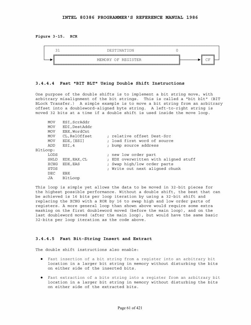
INTEL 80386 PROGRAMMER'S REFERENCE MANUAL 1986
Page 61 of 421
Figure 3-15. RCR
┌──────────────────────────────────────────────────────────────────────┐ │ 31 DESTINATION 0 │ │ ╔══════════════════════════════════════════════════╗ ╔════╗ │ └──►║ MEMORY OF REGISTER ╟───────►║ CF ╟─┘ ╚══════════════════════════════════════════════════╝ ╚════╝
3.4.4.4 Fast "BIT BLT" Using Double Shift Instructions
One purpose of the double shifts is to implement a bit string move, witharbitrary misalignment of the bit strings. This is called a "bit blt" (BITBLock Transfer.) A simple example is to move a bit string from an arbitraryoffset into a doubleword-aligned byte string. A left-to-right string ismoved 32 bits at a time if a double shift is used inside the move loop.
MOV ESI,ScrAddr MOV EDI,DestAddr MOV EBX,WordCnt MOV CL,RelOffset ; relative offset Dest-Src MOV EDX,[ESI] ; load first word of source ADD ESI,4 ; bump source addressBltLoop: LODS ; new low order part SHLD EDX,EAX,CL ; EDX overwritten with aligned stuff XCHG EDX,EAS ; Swap high/low order parts STOS ; Write out next aligned chunk DEC EBX JA BltLoop
This loop is simple yet allows the data to be moved in 32-bit pieces forthe highest possible performance. Without a double shift, the best that canbe achieved is 16 bits per loop iteration by using a 32-bit shift andreplacing the XCHG with a ROR by 16 to swap high and low order parts ofregisters. A more general loop than shown above would require some extramasking on the first doubleword moved (before the main loop), and on thelast doubleword moved (after the main loop), but would have the same basic32-bits per loop iteration as the code above.
3.4.4.5 Fast Bit-String Insert and Extract
The double shift instructions also enable:
● Fast insertion of a bit string from a register into an arbitrary bit location in a larger bit string in memory without disturbing the bits on either side of the inserted bits.
● Fast extraction of a bits string into a register from an arbitrary bit location in a larger bit string in memory without disturbing the bits on either side of the extracted bits.
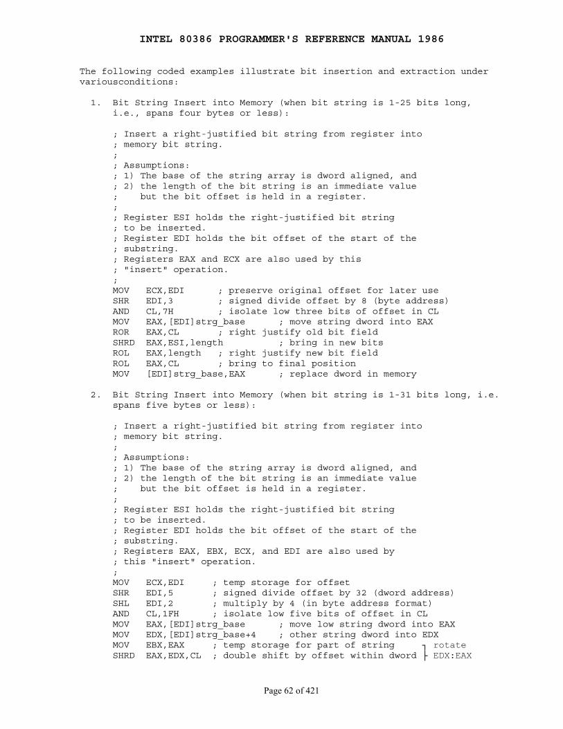
INTEL 80386 PROGRAMMER'S REFERENCE MANUAL 1986
Page 62 of 421
The following coded examples illustrate bit insertion and extraction undervariousconditions:
1. Bit String Insert into Memory (when bit string is 1-25 bits long, i.e., spans four bytes or less):
; Insert a right-justified bit string from register into ; memory bit string. ; ; Assumptions: ; 1) The base of the string array is dword aligned, and ; 2) the length of the bit string is an immediate value ; but the bit offset is held in a register. ; ; Register ESI holds the right-justified bit string ; to be inserted. ; Register EDI holds the bit offset of the start of the ; substring. ; Registers EAX and ECX are also used by this ; "insert" operation. ; MOV ECX,EDI ; preserve original offset for later use SHR EDI,3 ; signed divide offset by 8 (byte address) AND CL,7H ; isolate low three bits of offset in CL MOV EAX,[EDI]strg_base ; move string dword into EAX ROR EAX,CL ; right justify old bit field SHRD EAX,ESI,length ; bring in new bits ROL EAX,length ; right justify new bit field ROL EAX,CL ; bring to final position MOV [EDI]strg_base,EAX ; replace dword in memory
2. Bit String Insert into Memory (when bit string is 1-31 bits long, i.e. spans five bytes or less):
; Insert a right-justified bit string from register into ; memory bit string. ; ; Assumptions: ; 1) The base of the string array is dword aligned, and ; 2) the length of the bit string is an immediate value ; but the bit offset is held in a register. ; ; Register ESI holds the right-justified bit string ; to be inserted. ; Register EDI holds the bit offset of the start of the ; substring. ; Registers EAX, EBX, ECX, and EDI are also used by ; this "insert" operation. ; MOV ECX,EDI ; temp storage for offset SHR EDI,5 ; signed divide offset by 32 (dword address) SHL EDI,2 ; multiply by 4 (in byte address format) AND CL,1FH ; isolate low five bits of offset in CL MOV EAX,[EDI]strg_base ; move low string dword into EAX MOV EDX,[EDI]strg_base+4 ; other string dword into EDX MOV EBX,EAX ; temp storage for part of string ┐ rotate SHRD EAX,EDX,CL ; double shift by offset within dword ├ EDX:EAX
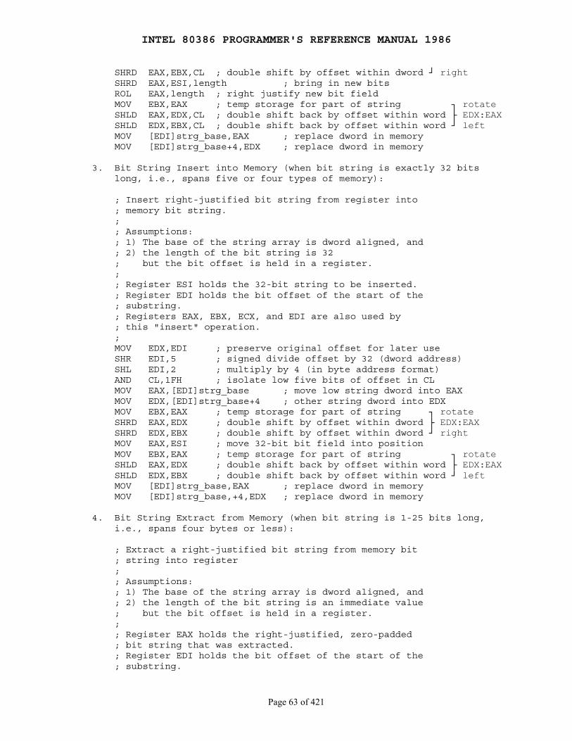
INTEL 80386 PROGRAMMER'S REFERENCE MANUAL 1986
Page 63 of 421
SHRD EAX,EBX,CL ; double shift by offset within dword ┘ right SHRD EAX,ESI,length ; bring in new bits ROL EAX,length ; right justify new bit field MOV EBX,EAX ; temp storage for part of string ┐ rotate SHLD EAX,EDX,CL ; double shift back by offset within word ├ EDX:EAX SHLD EDX,EBX,CL ; double shift back by offset within word ┘ left MOV [EDI]strg_base,EAX ; replace dword in memory MOV [EDI]strg_base+4,EDX ; replace dword in memory
3. Bit String Insert into Memory (when bit string is exactly 32 bits long, i.e., spans five or four types of memory):
; Insert right-justified bit string from register into ; memory bit string. ; ; Assumptions: ; 1) The base of the string array is dword aligned, and ; 2) the length of the bit string is 32 ; but the bit offset is held in a register. ; ; Register ESI holds the 32-bit string to be inserted. ; Register EDI holds the bit offset of the start of the ; substring. ; Registers EAX, EBX, ECX, and EDI are also used by ; this "insert" operation. ; MOV EDX,EDI ; preserve original offset for later use SHR EDI,5 ; signed divide offset by 32 (dword address) SHL EDI,2 ; multiply by 4 (in byte address format) AND CL,1FH ; isolate low five bits of offset in CL MOV EAX,[EDI]strg_base ; move low string dword into EAX MOV EDX,[EDI]strg_base+4 ; other string dword into EDX MOV EBX,EAX ; temp storage for part of string ┐ rotate SHRD EAX,EDX ; double shift by offset within dword ├ EDX:EAX SHRD EDX,EBX ; double shift by offset within dword ┘ right MOV EAX,ESI ; move 32-bit bit field into position MOV EBX,EAX ; temp storage for part of string ┐ rotate SHLD EAX,EDX ; double shift back by offset within word ├ EDX:EAX SHLD EDX,EBX ; double shift back by offset within word ┘ left MOV [EDI]strg_base,EAX ; replace dword in memory MOV [EDI]strg_base,+4,EDX ; replace dword in memory
4. Bit String Extract from Memory (when bit string is 1-25 bits long, i.e., spans four bytes or less):
; Extract a right-justified bit string from memory bit ; string into register ; ; Assumptions: ; 1) The base of the string array is dword aligned, and ; 2) the length of the bit string is an immediate value ; but the bit offset is held in a register. ; ; Register EAX holds the right-justified, zero-padded ; bit string that was extracted. ; Register EDI holds the bit offset of the start of the ; substring.
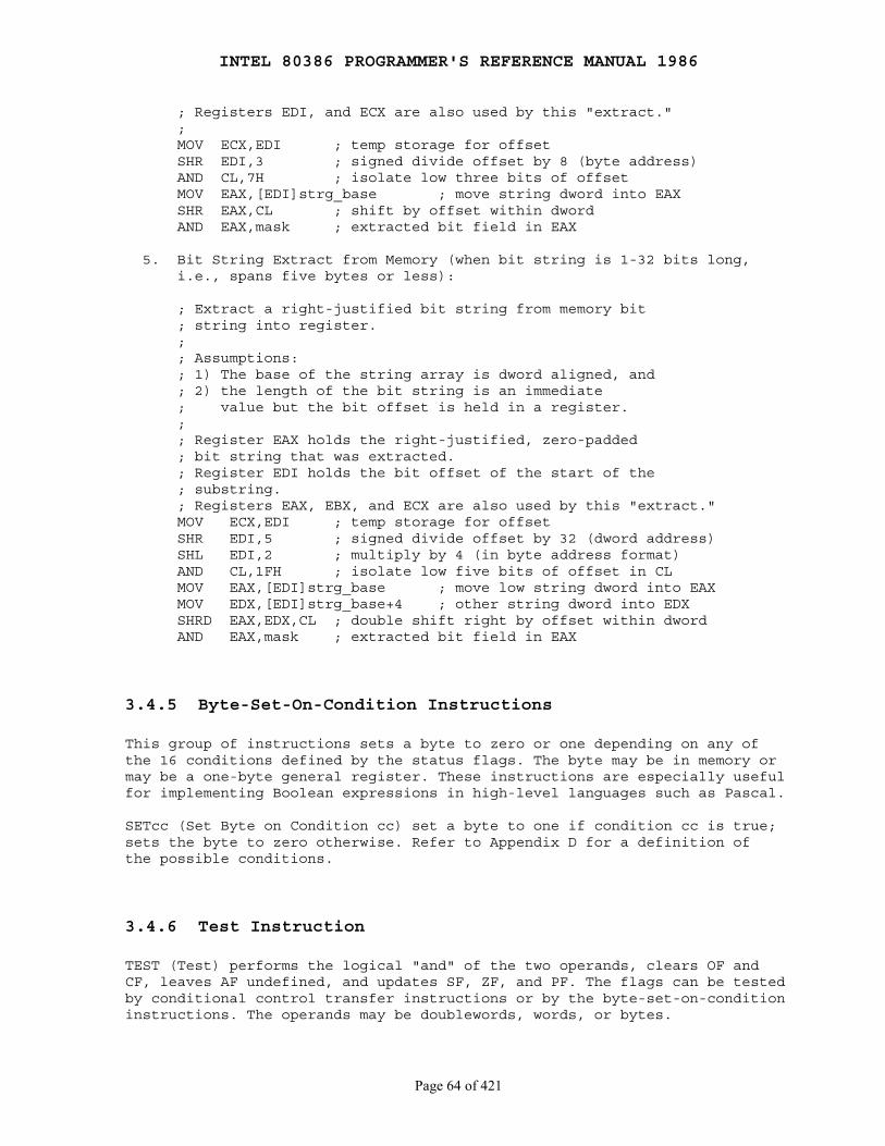
INTEL 80386 PROGRAMMER'S REFERENCE MANUAL 1986
Page 64 of 421
; Registers EDI, and ECX are also used by this "extract." ; MOV ECX,EDI ; temp storage for offset SHR EDI,3 ; signed divide offset by 8 (byte address) AND CL,7H ; isolate low three bits of offset MOV EAX,[EDI]strg_base ; move string dword into EAX SHR EAX,CL ; shift by offset within dword AND EAX,mask ; extracted bit field in EAX
5. Bit String Extract from Memory (when bit string is 1-32 bits long, i.e., spans five bytes or less):
; Extract a right-justified bit string from memory bit ; string into register. ; ; Assumptions: ; 1) The base of the string array is dword aligned, and ; 2) the length of the bit string is an immediate ; value but the bit offset is held in a register. ; ; Register EAX holds the right-justified, zero-padded ; bit string that was extracted. ; Register EDI holds the bit offset of the start of the ; substring. ; Registers EAX, EBX, and ECX are also used by this "extract." MOV ECX,EDI ; temp storage for offset SHR EDI,5 ; signed divide offset by 32 (dword address) SHL EDI,2 ; multiply by 4 (in byte address format) AND CL,1FH ; isolate low five bits of offset in CL MOV EAX,[EDI]strg_base ; move low string dword into EAX MOV EDX,[EDI]strg_base+4 ; other string dword into EDX SHRD EAX,EDX,CL ; double shift right by offset within dword AND EAX,mask ; extracted bit field in EAX
3.4.5 Byte-Set-On-Condition Instructions
This group of instructions sets a byte to zero or one depending on any ofthe 16 conditions defined by the status flags. The byte may be in memory ormay be a one-byte general register. These instructions are especially usefulfor implementing Boolean expressions in high-level languages such as Pascal.
SETcc (Set Byte on Condition cc) set a byte to one if condition cc is true;sets the byte to zero otherwise. Refer to Appendix D for a definition ofthe possible conditions.
3.4.6 Test Instruction
TEST (Test) performs the logical "and" of the two operands, clears OF andCF, leaves AF undefined, and updates SF, ZF, and PF. The flags can be testedby conditional control transfer instructions or by the byte-set-on-conditioninstructions. The operands may be doublewords, words, or bytes.
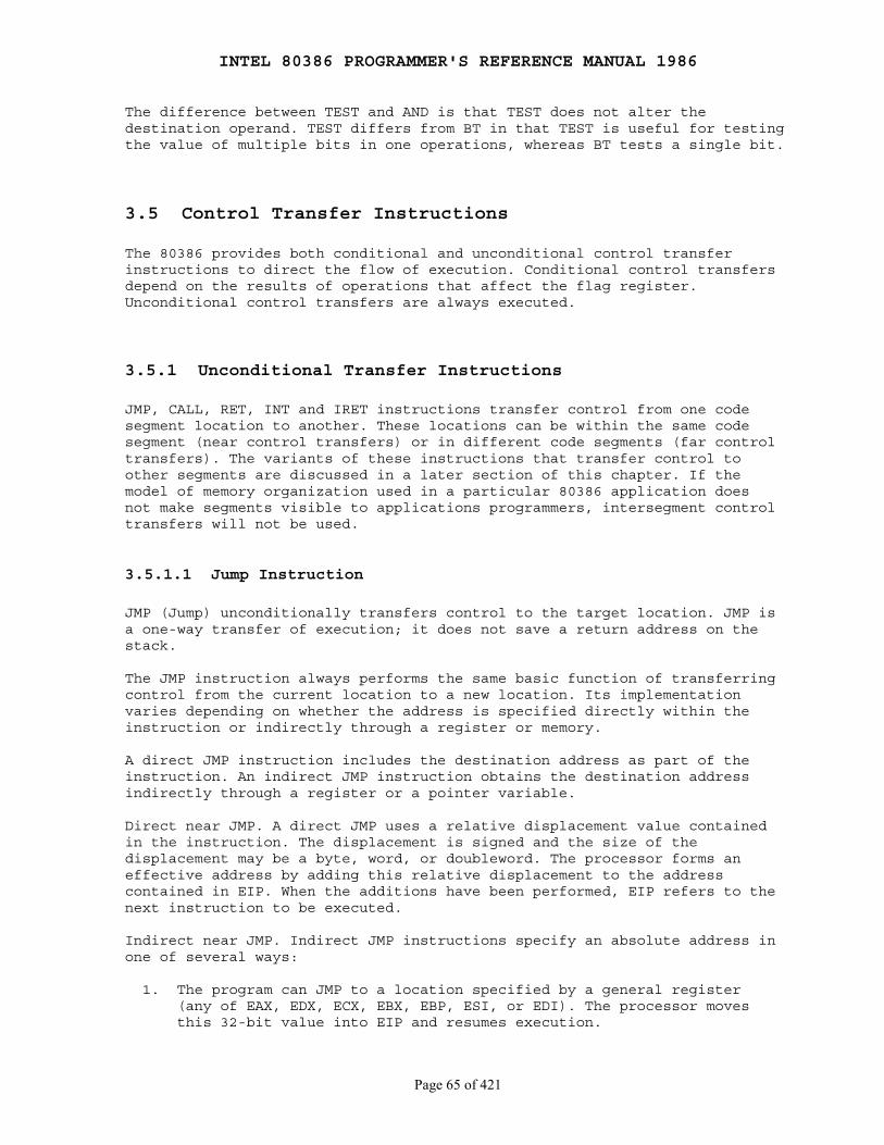
INTEL 80386 PROGRAMMER'S REFERENCE MANUAL 1986
Page 65 of 421
The difference between TEST and AND is that TEST does not alter thedestination operand. TEST differs from BT in that TEST is useful for testingthe value of multiple bits in one operations, whereas BT tests a single bit.
3.5 Control Transfer Instructions
The 80386 provides both conditional and unconditional control transferinstructions to direct the flow of execution. Conditional control transfersdepend on the results of operations that affect the flag register.Unconditional control transfers are always executed.
3.5.1 Unconditional Transfer Instructions
JMP, CALL, RET, INT and IRET instructions transfer control from one codesegment location to another. These locations can be within the same codesegment (near control transfers) or in different code segments (far controltransfers). The variants of these instructions that transfer control toother segments are discussed in a later section of this chapter. If themodel of memory organization used in a particular 80386 application doesnot make segments visible to applications programmers, intersegment controltransfers will not be used.
3.5.1.1 Jump Instruction
JMP (Jump) unconditionally transfers control to the target location. JMP isa one-way transfer of execution; it does not save a return address on thestack.
The JMP instruction always performs the same basic function of transferringcontrol from the current location to a new location. Its implementationvaries depending on whether the address is specified directly within theinstruction or indirectly through a register or memory.
A direct JMP instruction includes the destination address as part of theinstruction. An indirect JMP instruction obtains the destination addressindirectly through a register or a pointer variable.
Direct near JMP. A direct JMP uses a relative displacement value containedin the instruction. The displacement is signed and the size of thedisplacement may be a byte, word, or doubleword. The processor forms aneffective address by adding this relative displacement to the addresscontained in EIP. When the additions have been performed, EIP refers to thenext instruction to be executed.
Indirect near JMP. Indirect JMP instructions specify an absolute address inone of several ways:
1. The program can JMP to a location specified by a general register (any of EAX, EDX, ECX, EBX, EBP, ESI, or EDI). The processor moves this 32-bit value into EIP and resumes execution.

INTEL 80386 PROGRAMMER'S REFERENCE MANUAL 1986
Page 66 of 421
2. The processor can obtain the destination address from a memory operand specified in the instruction.
3. A register can modify the address of the memory pointer to select a destination address.
3.5.1.2 Call Instruction
CALL (Call Procedure) activates an out-of-line procedure, saving on thestack the address of the instruction following the CALL for later use by aRET (Return) instruction. CALL places the current value of EIP on the stack.The RET instruction in the called procedure uses this address to transfercontrol back to the calling program.
CALL instructions, like JMP instructions have relative, direct, andindirect versions.
Indirect CALL instructions specify an absolute address in one of theseways:
1. The program can CALL a location specified by a general register (any of EAX, EDX, ECX, EBX, EBP, ESI, or EDI). The processor moves this 32-bit value into EIP.
2. The processor can obtain the destination address from a memory operand specified in the instruction.
3.5.1.3 Return and Return-From-Interrupt Instruction
RET (Return From Procedure) terminates the execution of a procedure andtransfers control through a back-link on the stack to the program thatoriginally invoked the procedure. RET restores the value of EIP that wassaved on the stack by the previous CALL instruction.
RET instructions may optionally specify an immediate operand. By addingthis constant to the new top-of-stack pointer, RET effectively removes anyarguments that the calling program pushed on the stack before the executionof the CALL instruction.
IRET (Return From Interrupt) returns control to an interrupted procedure.IRET differs from RET in that it also pops the flags from the stack into theflags register. The flags are stored on the stack by the interruptmechanism.
3.5.2 Conditional Transfer Instructions
The conditional transfer instructions are jumps that may or may nottransfer control, depending on the state of the CPU flags when theinstruction executes.
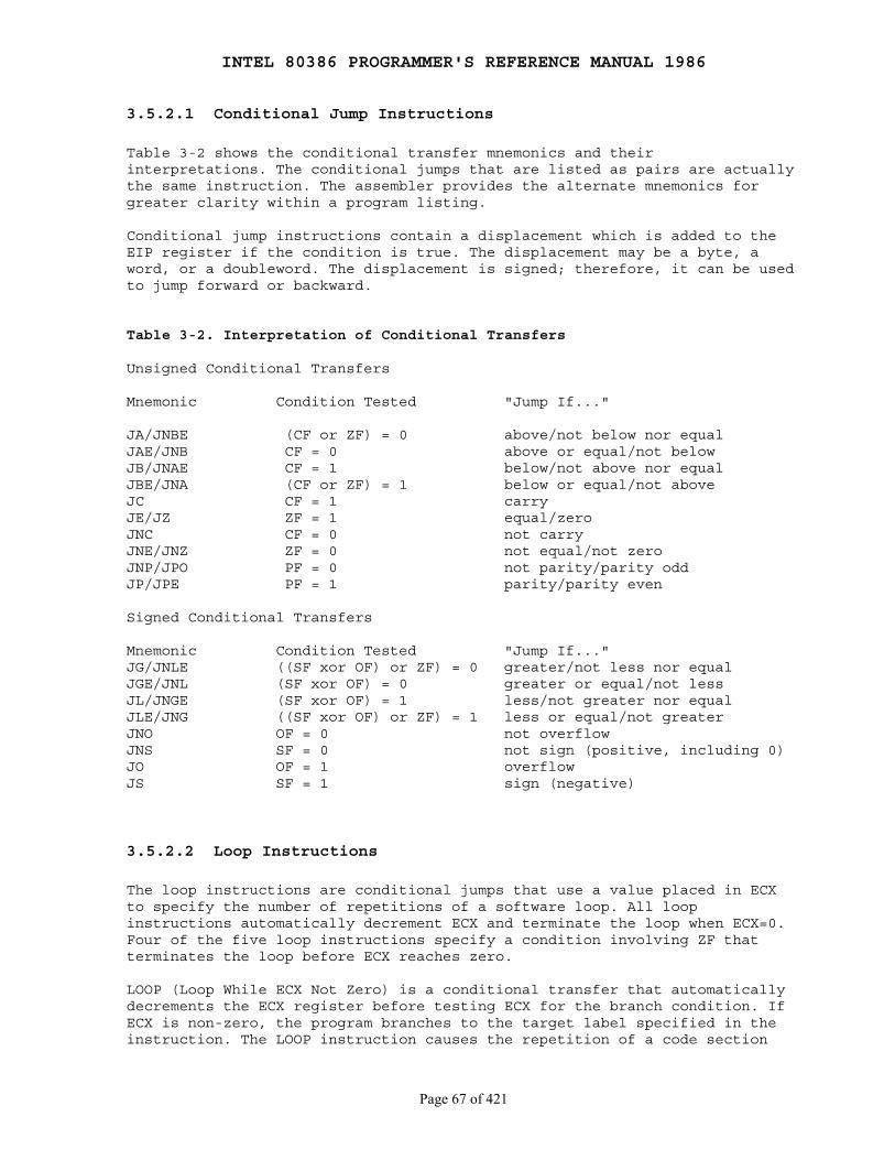
INTEL 80386 PROGRAMMER'S REFERENCE MANUAL 1986
Page 67 of 421
3.5.2.1 Conditional Jump Instructions
Table 3-2 shows the conditional transfer mnemonics and theirinterpretations. The conditional jumps that are listed as pairs are actuallythe same instruction. The assembler provides the alternate mnemonics forgreater clarity within a program listing.
Conditional jump instructions contain a displacement which is added to theEIP register if the condition is true. The displacement may be a byte, aword, or a doubleword. The displacement is signed; therefore, it can be usedto jump forward or backward.
Table 3-2. Interpretation of Conditional Transfers
Unsigned Conditional Transfers
Mnemonic Condition Tested "Jump If..."
JA/JNBE (CF or ZF) = 0 above/not below nor equalJAE/JNB CF = 0 above or equal/not belowJB/JNAE CF = 1 below/not above nor equalJBE/JNA (CF or ZF) = 1 below or equal/not aboveJC CF = 1 carryJE/JZ ZF = 1 equal/zeroJNC CF = 0 not carryJNE/JNZ ZF = 0 not equal/not zeroJNP/JPO PF = 0 not parity/parity oddJP/JPE PF = 1 parity/parity even
Signed Conditional Transfers
Mnemonic Condition Tested "Jump If..."JG/JNLE ((SF xor OF) or ZF) = 0 greater/not less nor equalJGE/JNL (SF xor OF) = 0 greater or equal/not lessJL/JNGE (SF xor OF) = 1 less/not greater nor equalJLE/JNG ((SF xor OF) or ZF) = 1 less or equal/not greaterJNO OF = 0 not overflowJNS SF = 0 not sign (positive, including 0)JO OF = 1 overflowJS SF = 1 sign (negative)
3.5.2.2 Loop Instructions
The loop instructions are conditional jumps that use a value placed in ECXto specify the number of repetitions of a software loop. All loopinstructions automatically decrement ECX and terminate the loop when ECX=0.Four of the five loop instructions specify a condition involving ZF thatterminates the loop before ECX reaches zero.
LOOP (Loop While ECX Not Zero) is a conditional transfer that automaticallydecrements the ECX register before testing ECX for the branch condition. IfECX is non-zero, the program branches to the target label specified in theinstruction. The LOOP instruction causes the repetition of a code section

INTEL 80386 PROGRAMMER'S REFERENCE MANUAL 1986
Page 68 of 421
until the operation of the LOOP instruction decrements ECX to a value ofzero. If LOOP finds ECX=0, control transfers to the instruction immediatelyfollowing the LOOP instruction. If the value of ECX is initially zero, thenthe LOOP executes 232 times.
LOOPE (Loop While Equal) and LOOPZ (Loop While Zero) are synonyms for thesame instruction. These instructions automatically decrement the ECXregister before testing ECX and ZF for the branch conditions. If ECX isnon-zero and ZF=1, the program branches to the target label specified in theinstruction. If LOOPE or LOOPZ finds that ECX=0 or ZF=0, control transfersto the instruction immediately following the LOOPE or LOOPZ instruction.
LOOPNE (Loop While Not Equal) and LOOPNZ (Loop While Not Zero) are synonymsfor the same instruction. These instructions automatically decrement the ECXregister before testing ECX and ZF for the branch conditions. If ECX isnon-zero and ZF=0, the program branches to the target label specified in theinstruction. If LOOPNE or LOOPNZ finds that ECX=0 or ZF=1, control transfersto the instruction immediately following the LOOPNE or LOOPNZ instruction.
3.5.2.3 Executing a Loop or Repeat Zero Times
JCXZ (Jump if ECX Zero) branches to the label specified in the instructionif it finds a value of zero in ECX. JCXZ is useful in combination with theLOOP instruction and with the string scan and compare instructions, all ofwhich decrement ECX. Sometimes, it is desirable to design a loop thatexecutes zero times if the count variable in ECX is initialized to zero.Because the LOOP instructions (and repeat prefixes) decrement ECX beforethey test it, a loop will execute 232 times if the program enters theloop with a zero value in ECX. A programmer may conveniently overcome thisproblem with JCXZ, which enables the program to branch around the codewithin the loop if ECX is zero when JCXZ executes. When used with repeatedstring scan and compare instructions, JCXZ can determine whether therepetitions terminated due to zero in ECX or due to satisfaction of thescan or compare conditions.
3.5.3 Software-Generated Interrupts
The INT n, INTO, and BOUND instructions allow the programmer to specify atransfer to an interrupt service routine from within a program.
INT n (Software Interrupt) activates the interrupt service routine thatcorresponds to the number coded within the instruction. The INT instructionmay specify any interrupt type. Programmers may use this flexibility toimplement multiple types of internal interrupts or to test the operation ofinterrupt service routines. (Interrupts 0-31 are reserved by Intel.) Theinterrupt service routine terminates with an IRET instruction that returnscontrol to the instruction that follows INT.
INTO (Interrupt on Overflow) invokes interrupt 4 if OF is set. Interrupt 4is reserved for this purpose. OF is set by several arithmetic, logical, andstring instructions.
INTEL 80386 PROGRAMMER'S REFERENCE MANUAL 1986
Page 69 of 421
BOUND (Detect Value Out of Range) verifies that the signed value containedin the specified register lies within specified limits. An interrupt (INT 5)occurs if the value contained in the register is less than the lower boundor greater than the upper bound.
The BOUND instruction includes two operands. The first operand specifiesthe register being tested. The second operand contains the effectiverelative address of the two signed BOUND limit values. The BOUND instructionassumes that the upper limit and lower limit are in adjacent memorylocations. These limit values cannot be register operands; if they are, aninvalid opcode exception occurs.
BOUND is useful for checking array bounds before using a new index value toaccess an element within the array. BOUND provides a simple way to check thevalue of an index register before the program overwrites information in alocation beyond the limit of the array.
The block of memory that specifies the lower and upper limits of an arraymight typically reside just before the array itself. This makes the arraybounds accessible at a constant offset from the beginning of the array.Because the address of the array will already be present in a register, thispractice avoids extra calculations to obtain the effective address of thearray bounds.
The upper and lower limit values may each be a word or a doubleword.
3.6 String and Character Translation Instructions
The instructions in this category operate on strings rather than on logicalor numeric values. Refer also to the section on I/O for information aboutthe string I/O instructions (also known as block I/O).
The power of 80386 string operations derives from the following features ofthe architecture:
1. A set of primitive string operations
MOVS ── Move String CMPS ── Compare string SCAS ── Scan string LODS ── Load string STOS ── Store string
2. Indirect, indexed addressing, with automatic incrementing or decrementing of the indexes.
Indexes:
ESI ── Source index register EDI ── Destination index register
Control flag:
DF ── Direction flag
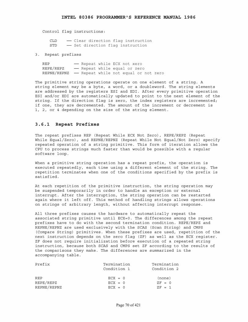
INTEL 80386 PROGRAMMER'S REFERENCE MANUAL 1986
Page 70 of 421
Control flag instructions:
CLD ── Clear direction flag instruction STD ── Set direction flag instruction
3. Repeat prefixes
REP ── Repeat while ECX not xero REPE/REPZ ── Repeat while equal or zero REPNE/REPNZ ── Repeat while not equal or not zero
The primitive string operations operate on one element of a string. Astring element may be a byte, a word, or a doubleword. The string elementsare addressed by the registers ESI and EDI. After every primitive operationESI and/or EDI are automatically updated to point to the next element of thestring. If the direction flag is zero, the index registers are incremented;if one, they are decremented. The amount of the increment or decrement is1, 2, or 4 depending on the size of the string element.
3.6.1 Repeat Prefixes
The repeat prefixes REP (Repeat While ECX Not Zero), REPE/REPZ (RepeatWhile Equal/Zero), and REPNE/REPNZ (Repeat While Not Equal/Not Zero) specifyrepeated operation of a string primitive. This form of iteration allows theCPU to process strings much faster than would be possible with a regularsoftware loop.
When a primitive string operation has a repeat prefix, the operation isexecuted repeatedly, each time using a different element of the string. Therepetition terminates when one of the conditions specified by the prefix issatisfied.
At each repetition of the primitive instruction, the string operation maybe suspended temporarily in order to handle an exception or externalinterrupt. After the interruption, the string operation can be restartedagain where it left off. This method of handling strings allows operationson strings of arbitrary length, without affecting interrupt response.
All three prefixes causes the hardware to automatically repeat theassociated string primitive until ECX=0. The differences among the repeatprefixes have to do with the second termination condition. REPE/REPZ andREPNE/REPNZ are used exclusively with the SCAS (Scan String) and CMPS(Compare String) primitives. When these prefixes are used, repetition of thenext instruction depends on the zero flag (ZF) as well as the ECX register.ZF does not require initialization before execution of a repeated stringinstruction, because both SCAS and CMPS set ZF according to the results ofthe comparisons they make. The differences are summarized in theaccompanying table.
Prefix Termination Termination Condition 1 Condition 2
REP ECX = 0 (none)REPE/REPZ ECX = 0 ZF = 0REPNE/REPNZ ECX = 0 ZF = 1
INTEL 80386 PROGRAMMER'S REFERENCE MANUAL 1986
Page 71 of 421
3.6.2 Indexing and Direction Flag Control
The addresses of the operands of string primitives are determined by theESI and EDI registers. ESI points to source operands. By default, ESI refersto a location in the segment indicated by the DS segment register. Asegment-override prefix may be used, however, to cause ESI to refer to CS,SS, ES, FS, or GS. EDI points to destination operands in the segmentindicated by ES; no segment override is possible. The use of two differentsegment registers in one instruction allows movement of strings betweendifferent segments.
This use of ESI and DSI has led to the descriptive names source index anddestination index for the ESI and EDI registers, respectively. In allcases other than string instructions, however, the ESI and EDI registers maybe used as general-purpose registers.
When ESI and EDI are used in string primitives, they are automaticallyincremented or decremented after to operation. The direction flag determineswhether they are incremented or decremented. The instruction CLD puts zeroin DF, causing the index registers to be incremented; the instruction STDputs one in DF, causing the index registers to be decremented. Programmersshould always put a known value in DF before using string instructions in aprocedure.
3.6.3 String Instructions
MOVS (Move String) moves the string element pointed to by ESI to thelocation pointed to by EDI. MOVSB operates on byte elements, MOVSW operateson word elements, and MOVSD operates on doublewords. The destination segmentregister cannot be overridden by a segment override prefix, but the sourcesegment register can be overridden.
The MOVS instruction, when accompanied by the REP prefix, operates as amemory-to-memory block transfer. To set up for this operation, the programmust initialize ECX and the register pairs ESI and EDI. ECX specifies thenumber of bytes, words, or doublewords in the block.
If DF=0, the program must point ESI to the first element of the sourcestring and point EDI to the destination address for the first element. IfDF=1, the program must point these two registers to the last element of thesource string and to the destination address for the last element,respectively.
CMPS (Compare Strings) subtracts the destination string element (at ES:EDI)from the source string element (at ESI) and updates the flags AF, SF, PF, CFand OF. If the string elements are equal, ZF=1; otherwise, ZF=0. If DF=0,the processor increments the memory pointers (ESI and EDI) for the twostrings. CMPSB compares bytes, CMPSW compares words, and CMPSD comparesdoublewords. The segment register used for the source address can be changedwith a segment override prefix while the destination segment registercannot be overridden.
SCAS (Scan String) subtracts the destination string element at ES:EDI fromEAX, AX, or AL and updates the flags AF, SF, ZF, PF, CF and OF. If the
INTEL 80386 PROGRAMMER'S REFERENCE MANUAL 1986
Page 72 of 421
values are equal, ZF=1; otherwise, ZF=0. If DF=0, the processor incrementsthe memory pointer (EDI) for the string. SCASB scans bytes; SCASW scanswords; SCASD scans doublewords. The destination segment register (ES) cannotbe overridden.
When either the REPE or REPNE prefix modifies either the SCAS or CMPSprimitives, the processor compares the value of the current string elementwith the value in EAX for doubleword elements, in AX for word elements, orin AL for byte elements. Termination of the repeated operation depends onthe resulting state of ZF as well as on the value in ECX.
LODS (Load String) places the source string element at ESI into EAX fordoubleword strings, into AX for word strings, or into AL for byte strings.LODS increments or decrements ESI according to DF.
STOS (Store String) places the source string element from EAX, AX, or ALinto the string at ES:DSI. STOS increments or decrements EDI according toDF.
3.7 Instructions for Block-Structured Languages
The instructions in this section provide machine-language support forfunctions normally found in high-level languages. These instructions includeENTER and LEAVE, which simplify the programming of procedures.
ENTER (Enter Procedure) creates a stack frame that may be used to implementthe scope rules of block-structured high-level languages. A LEAVEinstruction at the end of a procedure complements an ENTER at the beginningof the procedure to simplify stack management and to control access tovariables for nested procedures.
The ENTER instruction includes two parameters. The first parameterspecifies the number of bytes of dynamic storage to be allocated on thestack for the routine being entered. The second parameter corresponds to thelexical nesting level (0-31) of the routine. (Note that the lexical levelhas no relationship to either the protection privilege levels or to the I/Oprivilege level.)
The specified lexical level determines how many sets of stack framepointers the CPU copies into the new stack frame from the preceding frame.This list of stack frame pointers is sometimes called the display. The firstword of the display is a pointer to the last stack frame. This pointerenables a LEAVE instruction to reverse the action of the previous ENTERinstruction by effectively discarding the last stack frame.
Example: ENTER 2048,3
Allocates 2048 bytes of dynamic storage on the stack and sets up pointers to two previous stack frames in the stack frame that ENTER creates for this procedure.
After ENTER creates the new display for a procedure, it allocates thedynamic storage space for that procedure by decrementing ESP by the numberof bytes specified in the first parameter. This new value of ESP serves as astarting point for all PUSH and POP operations within that procedure.
INTEL 80386 PROGRAMMER'S REFERENCE MANUAL 1986
Page 73 of 421
To enable a procedure to address its display, ENTER leaves EBP pointing tothe beginning of the new stack frame. Data manipulation instructions thatspecify EBP as a base register implicitly address locations within the stacksegment instead of the data segment.
The ENTER instruction can be used in two ways: nested and non-nested. Ifthe lexical level is 0, the non-nested form is used. Since the secondoperand is 0, ENTER pushes EBP, copies ESP to EBP and then subtracts thefirst operand from ESP. The nested form of ENTER occurs when the secondparameter (lexical level) is not 0.
Figure 3-16 gives the formal definition of ENTER.
The main procedure (with other procedures nested within) operates at thehighest lexical level, level 1. The first procedure it calls operates at thenext deeper lexical level, level 2. A level 2 procedure can access thevariables of the main program which are at fixed locations specified by thecompiler. In the case of level 1, ENTER allocates only the requesteddynamic storage on the stack because there is no previous display to copy.
A program operating at a higher lexical level calling a program at a lowerlexical level requires that the called procedure should have access to thevariables of the calling program. ENTER provides this access through adisplay that provides addressability to the calling program's stack frame.
A procedure calling another procedure at the same lexical level impliesthat they are parallel procedures and that the called procedure should nothave access to the variables of the calling procedure. In this case, ENTERcopies only that portion of the display from the calling procedure whichrefers to previously nested procedures operating at higher lexical levels.The new stack frame does not include the pointer for addressing the callingprocedure's stack frame.
ENTER treats a reentrant procedure as a procedure calling another procedureat the same lexical level. In this case, each succeeding iteration of thereentrant procedure can address only its own variables and the variables ofthe calling procedures at higher lexical levels. A reentrant procedure canalways address its own variables; it does not require pointers to the stackframes of previous iterations.
By copying only the stack frame pointers of procedures at higher lexicallevels, ENTER makes sure that procedures access only those variables ofhigher lexical levels, not those at parallel lexical levels (see Figure3-17). Figures 3-18 through 3-21 demonstrate the actions of the ENTERinstruction if the modules shown in Figure 3-17 were to call one another inalphabetic order.
Block-structured high-level languages can use the lexical levels defined byENTER to control access to the variables of previously nested procedures.Referring to Figure 3-17 for example, if PROCEDURE A calls PROCEDURE Bwhich, in turn, calls PROCEDURE C, then PROCEDURE C will have access to thevariables of MAIN and PROCEDURE A, but not PROCEDURE B because they operateat the same lexical level. Following is the complete definition of access tovariables for Figure 3-17.
INTEL 80386 PROGRAMMER'S REFERENCE MANUAL 1986
Page 74 of 421
1. MAIN PROGRAM has variables at fixed locations.
2. PROCEDURE A can access only the fixed variables of MAIN.
3. PROCEDURE B can access only the variables of PROCEDURE A and MAIN. PROCEDURE B cannot access the variables of PROCEDURE C or PROCEDURE D.
4. PROCEDURE C can access only the variables of PROCEDURE A and MAIN. PROCEDURE C cannot access the variables of PROCEDURE B or PROCEDURE D.
5. PROCEDURE D can access the variables of PROCEDURE C, PROCEDURE A, and MAIN. PROCEDURE D cannot access the variables of PROCEDURE B.
ENTER at the beginning of the MAIN PROGRAM creates dynamic storage spacefor MAIN but copies no pointers. The first and only word in the displaypoints to itself because there is no previous value for LEAVE to return toEBP. See Figure 3-18.
After MAIN calls PROCEDURE A, ENTER creates a new display for PROCEDURE Awith the first word pointing to the previous value of EBP (BPM for LEAVE toreturn to the MAIN stack frame) and the second word pointing to the currentvalue of EBP. Procedure A can access variables in MAIN since MAIN is atlevel 1. Therefore the base for the dynamic storage for MAIN is at [EBP-2].All dynamic variables for MAIN are at a fixed offset from this value. SeeFigure 3-19.
After PROCEDURE A calls PROCEDURE B, ENTER creates a new display forPROCEDURE B with the first word pointing to the previous value of EBP, thesecond word pointing to the value of EBP for MAIN, and the third wordpointing to the value of EBP for A and the last word pointing to the currentEBP. B can access variables in A and MAIN by fetching from the display thebase addresses of the respective dynamic storage areas. See Figure 3-20.
After PROCEDURE B calls PROCEDURE C, ENTER creates a new display forPROCEDURE C with the first word pointing to the previous value of EBP, thesecond word pointing to the value of EBP for MAIN, and the third wordpointing to the EBP value for A and the third word pointing to the currentvalue of EBP. Because PROCEDURE B and PROCEDURE C have the same lexicallevel, PROCEDURE C is not allowed access to variables in B and thereforedoes not receive a pointer to the beginning of PROCEDURE B's stack frame.See Figure 3-21.
LEAVE (Leave Procedure) reverses the action of the previous ENTERinstruction. The LEAVE instruction does not include any operands. LEAVEcopies EBP to ESP to release all stack space allocated to the procedure bythe most recent ENTER instruction. Then LEAVE pops the old value of EBP fromthe stack. A subsequent RET instruction can then remove any arguments thatwere pushed on the stack by the calling program for use by the calledprocedure.
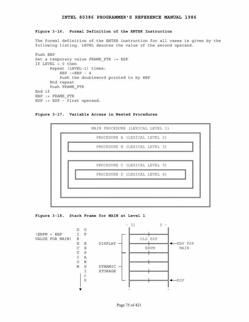
INTEL 80386 PROGRAMMER'S REFERENCE MANUAL 1986
Page 75 of 421
Figure 3-16. Formal Definition of the ENTER Instruction
The formal definition of the ENTER instruction for all cases is given by thefollowing listing. LEVEL denotes the value of the second operand.
Push EBPSet a temporary value FRAME_PTR := ESPIf LEVEL > 0 then Repeat (LEVEL-1) times: EBP :=EBP - 4 Push the doubleword pointed to by EBP End repeat Push FRAME_PTREnd ifEBP := FRAME_PTRESP := ESP - first operand.
Figure 3-17. Variable Access in Nested Procedures
╔════════════════════════════════════════════════════════════════╗ ║ MAIN PROCEDURE (LEXICAL LEVEL 1) ║ ║ ╔════════════════════════════════════════════════════════╗ ║ ║ ║ PROCEDURE A (LEXICAL LEVEL 2) ║ ║ ║ ║ ╔══════════════════════════════════════════════════╗ ║ ║ ║ ║ ║ PROCEDURE B (LEXICAL LEVEL 3) ║ ║ ║ ║ ║ ╚══════════════════════════════════════════════════╝ ║ ║ ║ ║ ║ ║ ║ ║ ╔══════════════════════════════════════════════════╗ ║ ║ ║ ║ ║ PROCEDURE C (LEXICAL LEVEL 3) ║ ║ ║ ║ ║ ║ ╔════════════════════════════════════════════╗ ║ ║ ║ ║ ║ ║ ║ PROCEDURE D (LEXICAL LEVEL 4) ║ ║ ║ ║ ║ ║ ║ ╚════════════════════════════════════════════╝ ║ ║ ║ ║ ║ ║ ║ ║ ║ ║ ║ ╚══════════════════════════════════════════════════╝ ║ ║ ║ ║ ║ ║ ║ ╚════════════════════════════════════════════════════════╝ ║ ║ ║ ╚════════════════════════════════════════════════════════════════╝
Figure 3-18. Stack Frame for MAIN at Level 1
· 31 0 · D O ║ ║(EBPM = EBP I F ┌─ ╠═══════╪═══════╣VALUE FOR MAIN) R │ ║ OLD ESP ║ E E DISPLAY ─┤ ╠═══════╪═══════╣◄──EBP FOR C X │ ║ EBPM ║ MAIN T P ╞═ ╠═══════╪═══════╣ I A │ ║ ║ O N │ ╠═══════╪═══════╣ N S DYNAMIC ─┤ ║ ║ I STORAGE │ ╠═══════╪═══════╣ │ O │ ║ ║ │ N └─ ╠═══════╪═══════╣◄──ESP │ ║ ║ ▼ · ·
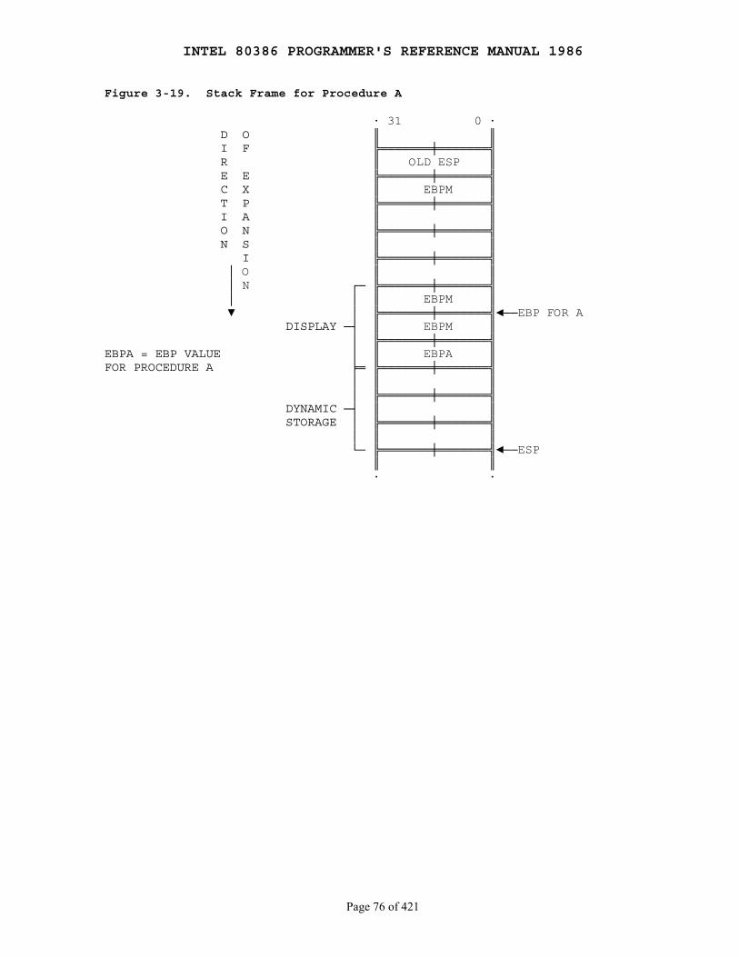
INTEL 80386 PROGRAMMER'S REFERENCE MANUAL 1986
Page 76 of 421
Figure 3-19. Stack Frame for Procedure A
· 31 0 · D O ║ ║ I F ╠═══════╪═══════╣ R ║ OLD ESP ║ E E ╠═══════╪═══════╣ C X ║ EBPM ║ T P ╠═══════╪═══════╣ I A ║ ║ O N ╠═══════╪═══════╣ N S ║ ║ I ╠═══════╪═══════╣ │ O ║ ║ │ N ┌─ ╠═══════╪═══════╣ │ │ ║ EBPM ║ ▼ │ ╠═══════╪═══════╣◄──EBP FOR A DISPLAY ─┤ ║ EBPM ║ │ ╠═══════╪═══════╣EBPA = EBP VALUE │ ║ EBPA ║FOR PROCEDURE A ╞═ ╠═══════╪═══════╣ │ ║ ║ │ ╠═══════╪═══════╣ DYNAMIC ─┤ ║ ║ STORAGE │ ╠═══════╪═══════╣ │ ║ ║ └─ ╠═══════╪═══════╣◄──ESP ║ ║ · ·

INTEL 80386 PROGRAMMER'S REFERENCE MANUAL 1986
Page 77 of 421
Figure 3-20. Stack Frame for Procedure B at Level 3 Called from A
· 31 0 · D O ║ ║ I F ╠═══════╪═══════╣ R ║ OLD ESP ║ E E ╠═══════╪═══════╣ C X ║ EBPM ║ T P ╠═══════╪═══════╣ I A ║ ║ O N ╠═══════╪═══════╣ N S ║ ║ I ╠═══════╪═══════╣ │ O ║ ║ │ N ╠═══════╪═══════╣ │ ║ EBPM ║ ▼ ╠═══════╪═══════╣ ║ EBPM ║ ╠═══════╪═══════╣ ║ EBPA ║ ╠═══════╪═══════╣ ║ ║ ╠═══════╪═══════╣ ║ ║ ╠═══════╪═══════╣ ║ ║ ┌─ ╠═══════╪═══════╣ │ ║ EBPA ║ │ ╠═══════╪═══════╣◄──EBP │ ║ EBPM ║ DISPLAY ─┤ ╠═══════╪═══════╣ │ ║ EBPA ║ │ ╠═══════╪═══════╣EBPB = EBP VALUE │ ║ EBPB ║FOR PROCEDURE B ╞═ ╠═══════╪═══════╣ │ ║ ║ │ ╠═══════╪═══════╣ DYNAMIC ─┤ ║ ║ STORAGE │ ╠═══════╪═══════╣ │ ║ ║ └─ ╠═══════╪═══════╣◄──ESP ║ ║ · ·

INTEL 80386 PROGRAMMER'S REFERENCE MANUAL 1986
Page 78 of 421
Figure 3-21. Stack Frame for Procedure C at Level 3 Called from B
· 31 0 · D O ║ ║ I F ╠═══════╪═══════╣ R ║ OLD ESP ║ E E ╠═══════╪═══════╣ C X ║ EBPM ║ T P ╠═══════╪═══════╣ I A ║ ║ O N ╠═══════╪═══════╣ N S ║ ║ I ╠═══════╪═══════╣ │ O ║ ║ │ N ╠═══════╪═══════╣ │ ║ EBPM ║ ▼ ╠═══════╪═══════╣ ║ EBPM ║ ╠═══════╪═══════╣ ║ EBPA ║ ╠═══════╪═══════╣ ║ ║ ╠═══════╪═══════╣ ║ ║ ╠═══════╪═══════╣ ║ ║ ┌─ ╠═══════╪═══════╣ │ ║ EBPA ║ │ ╠═══════╪═══════╣◄──EBP │ ║ EBPM ║ DISPLAY ─┤ ╠═══════╪═══════╣ │ ║ EBPA ║ │ ╠═══════╪═══════╣ │ ║ EBPB ║ ╞═ ╠═══════╪═══════╣ │ ║ ║ │ ╠═══════╪═══════╣ DYNAMIC ─┤ ║ ║ STORAGE │ ╠═══════╪═══════╣ │ ║ ║ └─ ╠═══════╪═══════╣◄──ESP ║ ║ · ·

INTEL 80386 PROGRAMMER'S REFERENCE MANUAL 1986
Page 79 of 421
3.8 Flag Control Instructions
The flag control instructions provide a method for directly changing thestate of bits in the flag register.
3.8.1 Carry and Direction Flag Control Instructions
The carry flag instructions are useful in conjunction withrotate-with-carry instructions RCL and RCR. They can initialize the carryflag, CF, to a known state before execution of a rotate that moves the carrybit into one end of the rotated operand.
The direction flag control instructions are specifically included to set orclear the direction flag, DF, which controls the left-to-right orright-to-left direction of string processing. If DF=0, the processorautomatically increments the string index registers, ESI and EDI, after eachexecution of a string primitive. If DF=1, the processor decrements theseindex registers. Programmers should use one of these instructions before anyprocedure that uses string instructions to insure that DF is set properly.
Flag Control Instruction Effect
STC (Set Carry Flag) CF ← 1CLC (Clear Carry Flag) CF ← 0CMC (Complement Carry Flag) CF ← NOT (CF)CLD (Clear Direction Flag) DF ← 0STD (Set Direction Flag) DF ← 1
3.8.2 Flag Transfer Instructions
Though specific instructions exist to alter CF and DF, there is no directmethod of altering the other applications-oriented flags. The flag transferinstructions allow a program to alter the other flag bits with the bitmanipulation instructions after transferring these flags to the stack or theAH register.
The instructions LAHF and SAHF deal with five of the status flags, whichare used primarily by the arithmetic and logical instructions.
LAHF (Load AH from Flags) copies SF, ZF, AF, PF, and CF to AH bits 7, 6, 4,2, and 0, respectively (see Figure 3-22). The contents of the remaining bits(5, 3, and 1) are undefined. The flags remain unaffected.
SAHF (Store AH into Flags) transfers bits 7, 6, 4, 2, and 0 from AH intoSF, ZF, AF, PF, and CF, respectively (see Figure 3-22).
The PUSHF and POPF instructions are not only useful for storing the flagsin memory where they can be examined and modified but are also useful forpreserving the state of the flags register while executing a procedure.

INTEL 80386 PROGRAMMER'S REFERENCE MANUAL 1986
Page 80 of 421
PUSHF (Push Flags) decrements ESP by two and then transfers the low-orderword of the flags register to the word at the top of stack pointed to by ESP(see Figure 3-23). The variant PUSHFD decrements ESP by four, thentransfers both words of the extended flags register to the top of the stackpointed to by ESP (the VM and RF flags are not moved, however).
POPF (Pop Flags) transfers specific bits from the word at the top of stackinto the low-order byte of the flag register (see Figure 3-23), thenincrements ESP by two. The variant POPFD transfers specific bits from thedoubleword at the top of the stack into the extended flags register (the RFand VM flags are not changed, however), then increments ESP by four.
Figure 3-22. LAHF and SAHF
7 6 5 4 3 2 1 0 ╔════╦════╦════╦════╦════╦════╦════╦════╗ ║ SF ║ ZF ║ UU ║ AF ║ UU ║ PF ║ UU ║ CF ║ ╚════╩════╩════╩════╩════╩════╩════╩════╝
LAHF LOADS FIVE FLAGS FROM THE FLAG REGISTER INTO REGISTER AH. SAHF STORES THESE SAME FIVE FLAGS FROM AH INTO THE FLAG REGISTER. THE BIT POSITION OF EACH FLAG IS THE SAME IN AH AS IT IS IN THE FLAG REGISTER. THE REMAINING BITS (MARKED UU) ARE RESERVED; DO NOT DEFINE.
3.9 Coprocessor Interface Instructions
A numerics coprocessor (e.g., the 80387 or 80287) provides an extension tothe instruction set of the base architecture. The coprocessor extends theinstruction set of the base architecture to support high-precision integerand floating-point calculations. This extended instruction set includesarithmetic, comparison, transcendental, and data transfer instructions. Thecoprocessor also contains a set of useful constants to enhance the speed ofnumeric calculations.
A program contains instructions for the coprocessor in line with theinstructions for the CPU. The system executes these instructions in the sameorder as they appear in the instruction stream. The coprocessor operatesconcurrently with the CPU to provide maximum throughput for numericcalculations.
The 80386 also has features to support emulation of the numericscoprocessor when the coprocessor is absent. The software emulation of thecoprocessor is transparent to application software but requires more timefor execution. Refer to Chapter 11 for more information on coprocessoremulation.
ESC (Escape) is a 5-bit sequence that begins the opcodes that identifyfloating point numeric instructions. The ESC pattern tells the 80386 to sendthe opcode and addresses of operands to the numerics coprocessor. Thenumerics coprocessor uses the escape instructions to performhigh-performance, high-precision floating point arithmetic that conforms tothe IEEE floating point standard 754.
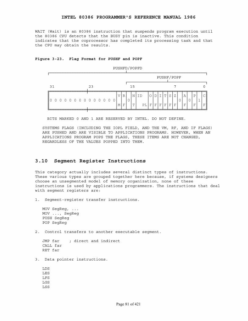
INTEL 80386 PROGRAMMER'S REFERENCE MANUAL 1986
Page 81 of 421
WAIT (Wait) is an 80386 instruction that suspends program execution untilthe 80386 CPU detects that the BUSY pin is inactive. This conditionindicates that the coprocessor has completed its processing task and thatthe CPU may obtain the results.
Figure 3-23. Flag Format for PUSHF and POPF
PUSHFD/POPFD ┌───────────────────────────────┴────────────────────────────────┐ PUSHF/POPF ┌────────────────┴───────────────┐ 31 23 15 7 0 ╔═══════════════╪═══════════╤═╤═╤═╤═╤════╤═╤═╤═╤═╤═╤═╤═╤═╤═╤═╤═╤═╗ ║ │V│R│ │N│ID │O│D│I│T│S│Z│ │A│ │P│ │C║ ║0 0 0 0 0 0 0 0 0 0 0 0 0 0│ │ │0│ │ │ │ │ │ │ │ │0│ │0│ │1│ ║ ║ │M│F│ │T│ PL│F│F│F│F│F│F│ │F│ │F│ │F║ ╚═══════════════╪═══════════╧═╧═╧═╧═╧════╧═╧═╧═╧═╧═╧═╧═╧═╧═╧═╧═╧═╝
BITS MARKED 0 AND 1 ARE RESERVED BY INTEL. DO NOT DEFINE.
SYSTEMS FLAGS (INCLUDING THE IOPL FIELD, AND THE VM, RF, AND IF FLAGS) ARE PUSHED AND ARE VISIBLE TO APPLICATIONS PROGRAMS. HOWEVER, WHEN AN APPLICATIONS PROGRAM POPS THE FLAGS, THESE ITEMS ARE NOT CHANGED, REGARDLESS OF THE VALUES POPPED INTO THEM.
3.10 Segment Register Instructions
This category actually includes several distinct types of instructions.These various types are grouped together here because, if systems designerschoose an unsegmented model of memory organization, none of theseinstructions is used by applications programmers. The instructions that dealwith segment registers are:
1. Segment-register transfer instructions.
MOV SegReg, ... MOV ..., SegReg PUSH SegReg POP SegReg
2. Control transfers to another executable segment.
JMP far ; direct and indirect CALL far RET far
3. Data pointer instructions.
LDS LES LFS LGS LSS

INTEL 80386 PROGRAMMER'S REFERENCE MANUAL 1986
Page 82 of 421
Note that the following interrupt-related instructions are different; allare capable of transferring control to another segment, but the use ofsegmentation is not apparent to the applications programmer.
INT nINTOBOUNDIRET
3.10.1 Segment-Register Transfer Instructions
The MOV, POP, and PUSH instructions also serve to load and store segmentregisters. These variants operate similarly to their general-registercounterparts except that one operand can be a segment register. MOV cannotmove segment register to a segment register. Neither POP nor MOV can place avalue in the code-segment register CS; only the far control-transferinstructions can change CS.
3.10.2 Far Control Transfer Instructions
The far control-transfer instructions transfer control to a location inanother segment by changing the content of the CS register.
Direct far JMP. Direct JMP instructions that specify a target locationoutside the current code segment contain a far pointer. This pointerconsists of a selector for the new code segment and an offset within the newsegment.
Indirect far JMP. Indirect JMP instructions that specify a target locationoutside the current code segment use a 48-bit variable to specify the farpointer.
Far CALL. An intersegment CALL places both the value of EIP and CS on thestack.
Far RET. An intersegment RET restores the values of both CS and EIP whichwere saved on the stack by the previous intersegment CALL instruction.
3.10.3 Data Pointer Instructions
The data pointer instructions load a pointer (consisting of a segmentselector and an offset) to a segment register and a general register.
LDS (Load Pointer Using DS) transfers a pointer variable from the sourceoperand to DS and the destination register. The source operand must be amemory operand, and the destination operand must be a general register. DSreceives the segment-selector of the pointer. The destination registerreceives the offset part of the pointer, which points to a specific locationwithin the segment.
INTEL 80386 PROGRAMMER'S REFERENCE MANUAL 1986
Page 83 of 421
Example: LDS ESI, STRING_X
Loads DS with the selector identifying the segment pointed to by aSTRING_X, and loads the offset of STRING_X into ESI. Specifying ESI as thedestination operand is a convenient way to prepare for a string operation ona source string that is not in the current data segment.
LES (Load Pointer Using ES) operates identically to LDS except that ESreceives the segment selector rather than DS.
Example: LES EDI, DESTINATION_X
Loads ES with the selector identifying the segment pointed to byDESTINATION_X, and loads the offset of DESTINATION_X into EDI. Thisinstruction provides a convenient way to select a destination for a stringoperation if the desired location is not in the current extra segment.
LFS (Load Pointer Using FS) operates identically to LDS except that FSreceives the segment selector rather than DS.
LGS (Load Pointer Using GS) operates identically to LDS except that GSreceives the segment selector rather than DS.
LSS (Load Pointer Using SS) operates identically to LDS except that SSreceives the segment selector rather than DS. This instruction isespecially important, because it allows the two registers that identify thestack (SS:ESP) to be changed in one uninterruptible operation. Unlike theother instructions which load SS, interrupts are not inhibited at the endof the LSS instruction. The other instructions (e.g., POP SS) inhibitinterrupts to permit the following instruction to load ESP, thereby formingan indivisible load of SS:ESP. Since both SS and ESP can be loaded by LSS,there is no need to inhibit interrupts.
3.11 Miscellaneous Instructions
The following instructions do not fit in any of the previous categories,but are nonetheless useful.
3.11.1 Address Calculation Instruction
LEA (Load Effective Address) transfers the offset of the source operand(rather than its value) to the destination operand. The source operand mustbe a memory operand, and the destination operand must be a general register.This instruction is especially useful for initializing registers before theexecution of the string primitives (ESI, EDI) or the XLAT instruction (EBX).The LEA can perform any indexing or scaling that may be needed.
Example: LEA EBX, EBCDIC_TABLE
Causes the processor to place the address of the starting location of thetable labeled EBCDIC_TABLE into EBX.
INTEL 80386 PROGRAMMER'S REFERENCE MANUAL 1986
Page 84 of 421
3.11.2 No-Operation Instruction
NOP (No Operation) occupies a byte of storage but affects nothing but theinstruction pointer, EIP.
3.11.3 Translate Instruction
XLAT (Translate) replaced a byte in the AL register with a byte from auser-coded translation table. When XLAT is executed, AL should have theunsigned index to the table addressed by EBX. XLAT changes the contents ofAL from table index to table entry. EBX is unchanged. The XLAT instructionis useful for translating from one coding system to another such as fromASCII to EBCDIC. The translate table may be up to 256 bytes long. Thevalue placed in the AL register serves as an index to the location of thecorresponding translation value.
INTEL 80386 PROGRAMMER'S REFERENCE MANUAL 1986
Page 85 of 421
PART II SYSTEMS PROGRAMMING
Chapter 4 Systems Architecture
────────────────────────────────────────────────────────────────────────────
Many of the architectural features of the 80386 are used only by systemsprogrammers. This chapter presents an overview of these aspects of thearchitecture.
The systems-level features of the 80386 architecture include:
Memory Management Protection Multitasking Input/Output Exceptions and Interrupts Initialization Coprocessing and Multiprocessing Debugging
These features are implemented by registers and instructions, all of whichare introduced in the following sections. The purpose of this chapter is notto explain each feature in detail, but rather to place the remainingchapters of Part II in perspective. Each mention in this chapter of aregister or instruction is either accompanied by an explanation or areference to a following chapter where detailed information can be obtained.
4.1 Systems Registers
The registers designed for use by systems programmers fall into theseclasses:
EFLAGS Memory-Management Registers Control Registers Debug Registers Test Registers
4.1.1 Systems Flags
The systems flags of the EFLAGS register control I/O, maskable interrupts,debugging, task switching, and enabling of virtual 8086 execution in aprotected, multitasking environment. These flags are highlighted in Figure4-1.
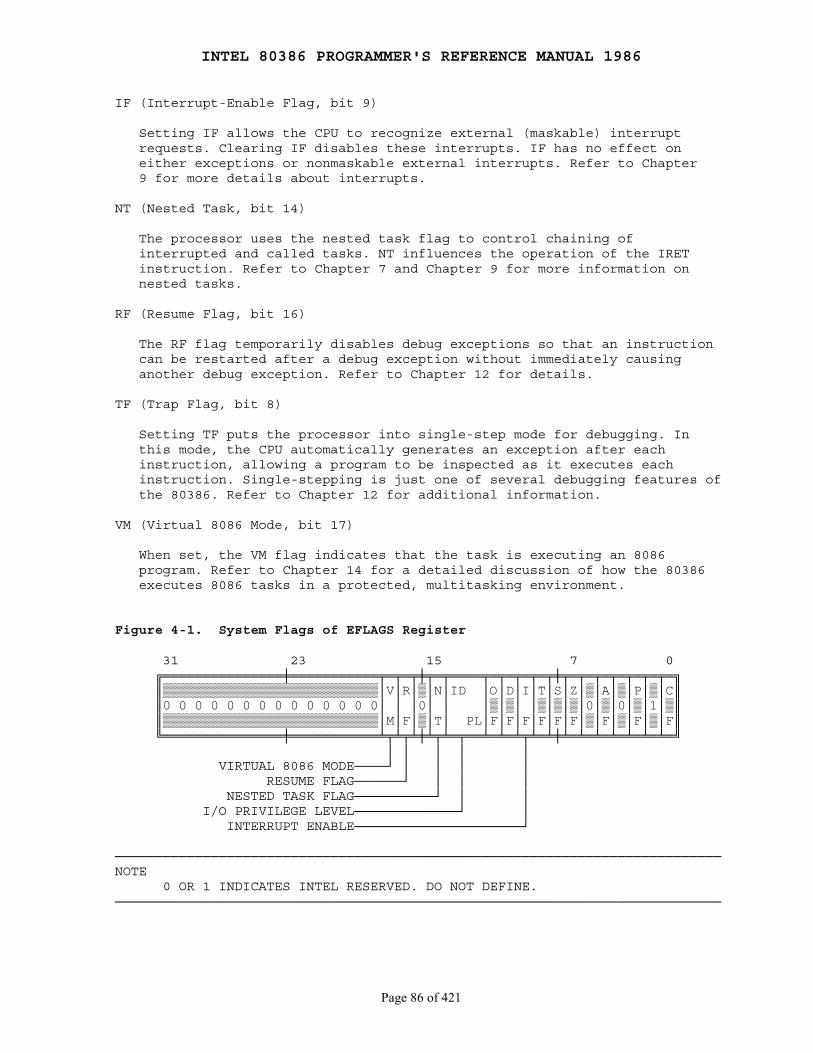
INTEL 80386 PROGRAMMER'S REFERENCE MANUAL 1986
Page 86 of 421
IF (Interrupt-Enable Flag, bit 9)
Setting IF allows the CPU to recognize external (maskable) interrupt requests. Clearing IF disables these interrupts. IF has no effect on either exceptions or nonmaskable external interrupts. Refer to Chapter 9 for more details about interrupts.
NT (Nested Task, bit 14)
The processor uses the nested task flag to control chaining of interrupted and called tasks. NT influences the operation of the IRET instruction. Refer to Chapter 7 and Chapter 9 for more information on nested tasks.
RF (Resume Flag, bit 16)
The RF flag temporarily disables debug exceptions so that an instruction can be restarted after a debug exception without immediately causing another debug exception. Refer to Chapter 12 for details.
TF (Trap Flag, bit 8)
Setting TF puts the processor into single-step mode for debugging. In this mode, the CPU automatically generates an exception after each instruction, allowing a program to be inspected as it executes each instruction. Single-stepping is just one of several debugging features of the 80386. Refer to Chapter 12 for additional information.
VM (Virtual 8086 Mode, bit 17)
When set, the VM flag indicates that the task is executing an 8086 program. Refer to Chapter 14 for a detailed discussion of how the 80386 executes 8086 tasks in a protected, multitasking environment.
Figure 4-1. System Flags of EFLAGS Register
31 23 15 7 0 ╔═══════════════╪═══════════╤═╤═╤╪╤═╤════╤═╤═╤═╤═╤╪╤═╤═╤═╤═╤═╤═╤═╗ ║▒▒▒▒▒▒▒▒▒▒▒▒▒▒▒▒▒▒▒▒▒▒▒▒▒▒▒│V│R│▒│N│ID │O│D│I│T│S│Z│▒│A│▒│P│▒│C║ ║0 0 0 0 0 0 0 0 0 0 0 0 0 0│ │ │0│ │ │▒│▒│ │▒│▒│▒│0│▒│0│▒│1│▒║ ║▒▒▒▒▒▒▒▒▒▒▒▒▒▒▒▒▒▒▒▒▒▒▒▒▒▒▒│M│F│▒│T│ PL│F│F│F│F│F│F│▒│F│▒│F│▒│F║ ╚═══════════════╪═══════════╧╤╧╤╧╪╧╤╧═╤══╧═╧═╧╤╧═╧╪╧═╧═╧═╧═╧═╧═╧═╝ │ │ │ │ │ VIRTUAL 8086 MODE────┘ │ │ │ │ RESUME FLAG──────┘ │ │ │ NESTED TASK FLAG──────────┘ │ │ I/O PRIVILEGE LEVEL─────────────┘ │ INTERRUPT ENABLE─────────────────────┘
────────────────────────────────────────────────────────────────────────────NOTE 0 OR 1 INDICATES INTEL RESERVED. DO NOT DEFINE.────────────────────────────────────────────────────────────────────────────
INTEL 80386 PROGRAMMER'S REFERENCE MANUAL 1986
Page 87 of 421
4.1.2 Memory-Management Registers
Four registers of the 80386 locate the data structures that controlsegmented memory management:
GDTR Global Descriptor Table RegisterLDTR Local Descriptor Table Register
These registers point to the segment descriptor tables GDT and LDT. Refer to Chapter 5 for an explanation of addressing via descriptor tables.
IDTR Interrupt Descriptor Table Register
This register points to a table of entry points for interrupt handlers (the IDT). Refer to Chapter 9 for details of the interrupt mechanism.
TR Task Register
This register points to the information needed by the processor to define the current task. Refer to Chapter 7 for a description of the multitasking features of the 80386.
4.1.3 Control Registers
Figure 4-2 shows the format of the 80386 control registers CR0, CR2, andCR3. These registers are accessible to systems programmers only via variantsof the MOV instruction, which allow them to be loaded from or stored ingeneral registers; for example:
MOV EAX, CR0MOV CR3, EBX
CR0 contains system control flags, which control or indicate conditionsthat apply to the system as a whole, not to an individual task.
EM (Emulation, bit 2)
EM indicates whether coprocessor functions are to be emulated. Refer to Chapter 11 for details.
ET (Extension Type, bit 4)
ET indicates the type of coprocessor present in the system (80287 or 80387). Refer to Chapter 11 and Chapter 10 for details.
MP (Math Present, bit 1)
MP controls the function of the WAIT instruction, which is used to coordinate a coprocessor. Refer to Chapter 11 for details.
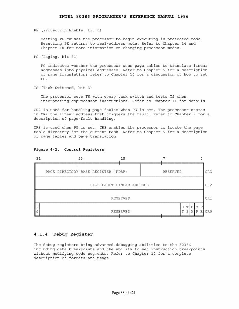
INTEL 80386 PROGRAMMER'S REFERENCE MANUAL 1986
Page 88 of 421
PE (Protection Enable, bit 0)
Setting PE causes the processor to begin executing in protected mode. Resetting PE returns to real-address mode. Refer to Chapter 14 and Chapter 10 for more information on changing processor modes.
PG (Paging, bit 31)
PG indicates whether the processor uses page tables to translate linear addresses into physical addresses. Refer to Chapter 5 for a description of page translation; refer to Chapter 10 for a discussion of how to set PG.
TS (Task Switched, bit 3)
The processor sets TS with every task switch and tests TS when interpreting coprocessor instructions. Refer to Chapter 11 for details.
CR2 is used for handling page faults when PG is set. The processor storesin CR2 the linear address that triggers the fault. Refer to Chapter 9 for adescription of page-fault handling.
CR3 is used when PG is set. CR3 enables the processor to locate the pagetable directory for the current task. Refer to Chapter 5 for a descriptionof page tables and page translation.
Figure 4-2. Control Registers
31 23 15 7 0╔═════════════════╪═════════════════╪════════╦════════╪═════════════════╗║ ║ ║║ PAGE DIRECTORY BASE REGISTER (PDBR) ║ RESERVED ║CR3╟────────────────────────────────────────────╨──────────────────────────╢║ ║║ PAGE FAULT LINEAR ADDRESS ║CR2╟───────────────────────────────────────────────────────────────────────╢║ ║║ RESERVED ║CR1╟─┬───────────────────────────────────────────────────────────┬─┬─┬─┬─┬─╢║P│ │E│T│E│M│P║║G│ RESERVED │T│S│M│P│E║CR0╚═╧═══════════════╪═════════════════╪═════════════════╪═══════╧═╧═╧═╧═╧═╝
4.1.4 Debug Register
The debug registers bring advanced debugging abilities to the 80386,including data breakpoints and the ability to set instruction breakpointswithout modifying code segments. Refer to Chapter 12 for a completedescription of formats and usage.

INTEL 80386 PROGRAMMER'S REFERENCE MANUAL 1986
Page 89 of 421
4.1.5 Test Registers
The test registers are not a standard part of the 80386 architecture. Theyare provided solely to enable confidence testing of the translationlookaside buffer (TLB), the cache used for storing information from pagetables. Chapter 12 explains how to use these registers.
4.2 Systems Instructions
Systems instructions deal with such functions as:
1. Verification of pointer parameters (refer to Chapter 6):
ARPL ── Adjust RPL LAR ── Load Access Rights LSL ── Load Segment Limit VERR ── Verify for Reading VERW ── Verify for Writing
2. Addressing descriptor tables (refer to Chaper 5):
LLDT ── Load LDT Register SLDT ── Store LDT Register LGDT ── Load GDT Register SGDT ── Store GDT Register
3. Multitasking (refer to Chapter 7):
LTR ── Load Task Register STR ── Store Task Register
4. Coprocessing and Multiprocessing (refer to Chapter 11):
CLTS ── Clear Task-Switched Flag ESC ── Escape instructions WAIT ── Wait until Coprocessor not Busy LOCK ── Assert Bus-Lock Signal
5. Input and Output (refer to Chapter 8):
IN ── Input OUT ── Output INS ── Input String OUTS ── Output String
6. Interrupt control (refer to Chapter 9):
CLI ── Clear Interrupt-Enable Flag STI ── Set Interrupt-Enable Flag LIDT ── Load IDT Register SIDT ── Store IDT Register
INTEL 80386 PROGRAMMER'S REFERENCE MANUAL 1986
Page 90 of 421
7. Debugging (refer to Chapter 12):
MOV ── Move to and from debug registers
8. TLB testing (refer to Chapter 10):
MOV ── Move to and from test registers
9. System Control:
SMSW ── Set MSW LMSW ── Load MSW HLT ── Halt Processor MOV ── Move to and from control registers
The instructions SMSW and LMSW are provided for compatibility with the80286 processor. 80386 programs access the MSW in CR0 via variants of theMOV instruction. HLT stops the processor until receipt of an INTR or RESETsignal.
In addition to the chapters cited above, detailed information about each ofthese instructions can be found in the instruction reference chapter,Chapter 17.
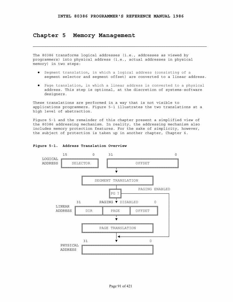
INTEL 80386 PROGRAMMER'S REFERENCE MANUAL 1986
Page 91 of 421
Chapter 5 Memory Management
────────────────────────────────────────────────────────────────────────────
The 80386 transforms logical addresses (i.e., addresses as viewed byprogrammers) into physical address (i.e., actual addresses in physicalmemory) in two steps:
● Segment translation, in which a logical address (consisting of a segment selector and segment offset) are converted to a linear address.
● Page translation, in which a linear address is converted to a physical address. This step is optional, at the discretion of systems-software designers.
These translations are performed in a way that is not visible toapplications programmers. Figure 5-1 illustrates the two translations at ahigh level of abstraction.
Figure 5-1 and the remainder of this chapter present a simplified view ofthe 80386 addressing mechanism. In reality, the addressing mechanism alsoincludes memory protection features. For the sake of simplicity, however,the subject of protection is taken up in another chapter, Chapter 6.
Figure 5-1. Address Translation Overview
15 0 31 0 LOGICAL ╔═══════════════╗ ╔══════════════════════════════╗ ADDRESS ║ SELECTOR ║ ║ OFFSET ║ ╚═══════════════╝ ╚═══╤══════════════════════════╝ ▼ ╔══════════════════════════════╗ ║ SEGMENT TRANSLATION ║ ╚══════════════╤═══════════════╝ ╔══╧═╗ PAGING ENABLED ║PG ?╟────────────────────┐ ╚══╤═╝ │ 31 PAGING ▼ DISABLED 0 │ LINEAR ╔═══════════╦═══════════╦═══════════╗ │ ADDRESS ║ DIR ║ PAGE ║ OFFSET ║ │ ╚═══════════╩═════╤═════╩═══════════╝ │ ▼ │ ╔══════════════════════════════╗ │ ║ PAGE TRANSLATION ║ │ ╚══════════════╤═══════════════╝ │ │◄─────────────────────┘ 31 ▼ 0 PHYSICAL ╔══════════════════════════════╗ ADDRESS ║ ║ ╚══════════════════════════════╝
INTEL 80386 PROGRAMMER'S REFERENCE MANUAL 1986
Page 92 of 421
5.1 Segment Translation
Figure 5-2 shows in more detail how the processor converts a logicaladdress into a linear address.
To perform this translation, the processor uses the following datastructures:
● Descriptors ● Descriptor tables ● Selectors ● Segment Registers
5.1.1 Descriptors
The segment descriptor provides the processor with the data it needs to mapa logical address into a linear address. Descriptors are created bycompilers, linkers, loaders, or the operating system, not by applicationsprogrammers. Figure 5-3 illustrates the two general descriptor formats. Alltypes of segment descriptors take one of these formats. Segment-descriptorfields are:
BASE: Defines the location of the segment within the 4 gigabyte linearaddress space. The processor concatenates the three fragments of the baseaddress to form a single 32-bit value.
LIMIT: Defines the size of the segment. When the processor concatenates thetwo parts of the limit field, a 20-bit value results. The processorinterprets the limit field in one of two ways, depending on the setting ofthe granularity bit:
1. In units of one byte, to define a limit of up to 1 megabyte.
2. In units of 4 Kilobytes, to define a limit of up to 4 gigabytes. The limit is shifted left by 12 bits when loaded, and low-order one-bits are inserted.
Granularity bit: Specifies the units with which the LIMIT field isinterpreted. When thebit is clear, the limit is interpreted in units of onebyte; when set, the limit is interpreted in units of 4 Kilobytes.
TYPE: Distinguishes between various kinds of descriptors.
DPL (Descriptor Privilege Level): Used by the protection mechanism (referto Chapter 6).
Segment-Present bit: If this bit is zero, the descriptor is not valid foruse in address transformation; the processor will signal an exception when aselector for the descriptor is loaded into a segment register. Figure 5-4shows the format of a descriptor when the present-bit is zero. The operatingsystem is free to use the locations marked AVAILABLE. Operating systems thatimplement segment-based virtual memory clear the present bit in either ofthese cases:
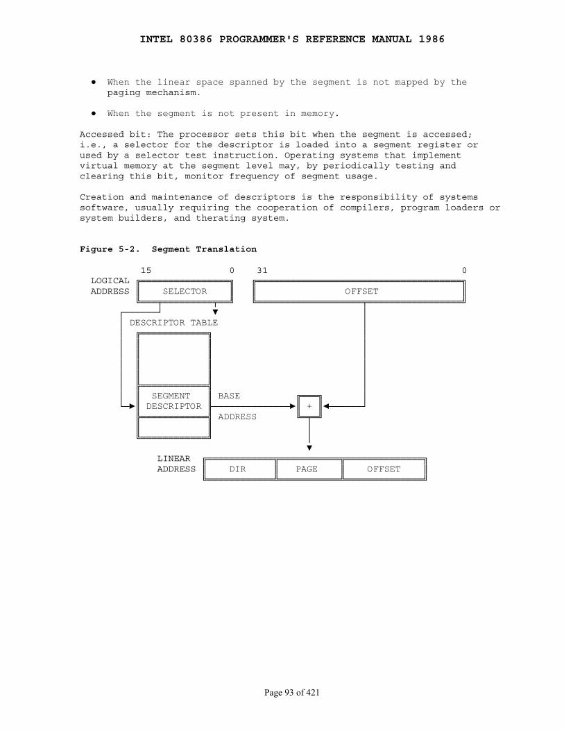
INTEL 80386 PROGRAMMER'S REFERENCE MANUAL 1986
Page 93 of 421
● When the linear space spanned by the segment is not mapped by the paging mechanism.
● When the segment is not present in memory.
Accessed bit: The processor sets this bit when the segment is accessed;i.e., a selector for the descriptor is loaded into a segment register orused by a selector test instruction. Operating systems that implementvirtual memory at the segment level may, by periodically testing andclearing this bit, monitor frequency of segment usage.
Creation and maintenance of descriptors is the responsibility of systemssoftware, usually requiring the cooperation of compilers, program loaders orsystem builders, and therating system.
Figure 5-2. Segment Translation
15 0 31 0 LOGICAL ╔════════════════╗ ╔═════════════════════════════════════╗ ADDRESS ║ SELECTOR ║ ║ OFFSET ║ ╚═══╤═════════╤══╝ ╚═══════════════════╤═════════════════╝ ┌──────┘ ▼ │ │ DESCRIPTOR TABLE │ │ ╔════════════╗ │ │ ║ ║ │ │ ║ ║ │ │ ║ ║ │ │ ║ ║ │ │ ╠════════════╣ │ │ ║ SEGMENT ║ BASE ╔═══╗ │ └─►║ DESCRIPTOR ╟──────────────►║ + ║◄──────┘ ╠════════════╣ ADDRESS ╚═╤═╝ ║ ║ │ ╚════════════╝ │ ▼ LINEAR ╔════════════╦═══════════╦══════════════╗ ADDRESS ║ DIR ║ PAGE ║ OFFSET ║ ╚════════════╩═══════════╩══════════════╝

INTEL 80386 PROGRAMMER'S REFERENCE MANUAL 1986
Page 94 of 421
Figure 5-3. General Segment-Descriptor Format
DESCRIPTORS USED FOR APPLICATIONS CODE AND DATA SEGMENTS
31 23 15 7 0 ╔═════════════════╪═╤═╤═╤═╤═════════╪═╤═════╤═╤═════╤═╪═════════════════╗ ║ │ │ │ │A│ │ │ │ │ │ │ ║ ║ BASE 31..24 │G│X│O│V│ LIMIT │P│ DPL │1│ TYPE│A│ BASE 23..16 ║ 4 ║ │ │ │ │L│ 19..16 │ │ │ │ │ │ ║ ╟─────────────────┴─┴─┴─┴─┴─────────┼─┴─────┴─┴─────┴─┴─────────────────╢ ║ │ ║ ║ SEGMENT BASE 15..0 │ SEGMENT LIMIT 15..0 ║ 0 ║ │ ║ ╚═════════════════╪═════════════════╪═════════════════╪═════════════════╝
DESCRIPTORS USED FOR SPECIAL SYSTEM SEGMENTS
31 23 15 7 0 ╔═════════════════╪═╤═╤═╤═╤═════════╪═╤═════╤═╤═══════╪═════════════════╗ ║ │ │ │ │A│ │ │ │ │ │ ║ ║ BASE 31..24 │G│X│O│V│ LIMIT │P│ DPL │0│ TYPE │ BASE 23..16 ║ 4 ║ │ │ │ │L│ 19..16 │ │ │ │ │ ║ ╟─────────────────┴─┴─┴─┴─┴─────────┼─┴─────┴─┴───────┴─────────────────╢ ║ │ ║ ║ SEGMENT BASE 15..0 │ SEGMENT LIMIT 15..0 ║ 0 ║ │ ║ ╚═════════════════╪═════════════════╪═════════════════╪═════════════════╝
A - ACCESSED AVL - AVAILABLE FOR USE BY SYSTEMS PROGRAMMERS DPL - DESCRIPTOR PRIVILEGE LEVEL G - GRANULARITY P - SEGMENT PRESENT
5.1.2 Descriptor Tables
Segment descriptors are stored in either of two kinds of descriptor table:
● The global descriptor table (GDT) ● A local descriptor table (LDT)
A descriptor table is simply a memory array of 8-byte entries that containdescriptors, as Figure 5-5 shows. A descriptor table is variable in lengthand may contain up to 8192 (213) descriptors. The first entry of the GDT(INDEX=0) is not used by the processor, however.
The processor locates the GDT and the current LDT in memory by means of theGDTR and LDTR registers. These registers store the base addresses of thetables in the linear address space and store the segment limits. Theinstructions LGDT and SGDT give access to the GDTR; the instructions LLDTand SLDT give access to the LDTR.

INTEL 80386 PROGRAMMER'S REFERENCE MANUAL 1986
Page 95 of 421
Figure 5-4. Format of Not-Present Descriptor
31 23 15 7 0 ╔═════════════════╪═════════════════╪═╤═════╤═╤═══════╪═════════════════╗ ║ │ │ │ │ │ ║ ║ AVAILABLE │O│ DPL │S│ TYPE │ AVAILABLE ║ 4 ║ │ │ │ │ │ ║ ╟───────────────────────────────────┴─┴─────┴─┴───────┴─────────────────╢ ║ ║ ║ AVAILABLE ║ 0 ║ ║ ╚═════════════════╪═════════════════╪═════════════════╪═════════════════╝
Figure 5-5. Descriptor Tables
GLOBAL DESCRIPTOR TABLE LOCAL DESCRIPTOR TABLE ╔══════╤═════╤═════╤══════╗ ╔══════╤═════╤═════╤══════╗ ║ │ │ │ ║ ║ │ │ │ ║ ╟──────┴─────┼─────┴──────╢ ╟──────┴─────┼─────┴──────╢ ║ │ ║ M ║ │ ║ M ╚════════════╧════════════╝ ╚════════════╧════════════╝ | | | | | | | | ╔══════╤═════╤═════╤══════╗ ╔══════╤═════╤═════╤══════╗ ║ │ │ │ ║ ║ │ │ │ ║ ╟──────┴─────┼─────┴──────╢ ╟──────┴─────┼─────┴──────╢ ║ │ ║ N + 3 ║ │ ║ N + 3 ╠══════╤═════╪═════╤══════╣ ╠══════╤═════╪═════╤══════╣ ║ │ │ │ ║ ║ │ │ │ ║ ╟──────┴─────┼─────┴──────╢ ╟──────┴─────┼─────┴──────╢ ║ │ ║ N + 2 ║ │ ║ N + 2 ╠══════╤═════╪═════╤══════╣ ╠══════╤═════╪═════╤══════╣ ║ │ │ │ ║ ║ │ │ │ ║ ╟──────┴─────┼─────┴──────╢ ╟──────┴─────┼─────┴──────╢ ║ │ ║ N + 1 ║ │ ║ N + 1 ╠══════╤═════╪═════╤══════╣ ╠══════╤═════╪═════╤══════╣ ║ │ │ │ ║ ║ │ │ │ ║ ╟──────┴─────┼─────┴──────╢ ╟──────┴─────┼─────┴──────╢ ║ │ ║ N ║ │ ║ N ╚════════════╧════════════╝ ╚════════════╧════════════╝ | | | | | | | | ╔══════╤═════╤═════╤══════╗ ╔══════╤═════╤═════╤══════╗ ║ │ │ │ ║ ║ │ │ │ ║ ╟──────┴──(UNUSED)─┴──────╢ ╟──────┴─────┼─────┴──────╢ ║ │ ║ ║ │ ║ ╚════════════╧════════════╝ ╚════════════╧════════════╝ ▲ ▲ ╔═════════════════════╗ │ ╔═════════════════════╗ │ ║ GDTR ╟──┘ ║ LDTR ╟──┘ ╚═════════════════════╝ ╚═════════════════════╝

INTEL 80386 PROGRAMMER'S REFERENCE MANUAL 1986
Page 96 of 421
5.1.3 Selectors
The selector portion of a logical address identifies a descriptor byspecifying a descriptor table and indexing a descriptor within that table.Selectors may be visible to applications programs as a field within apointer variable, but the values of selectors are usually assigned (fixedup) by linkers or linking loaders. Figure 5-6 shows the format of aselector.
Index: Selects one of 8192 descriptors in a descriptor table. The processorsimply multiplies this index value by 8 (the length of a descriptor), andadds the result to the base address of the descriptor table in order toaccess the appropriate segment descriptor in the table.
Table Indicator: Specifies to which descriptor table the selector refers. Azero indicates the GDT; a one indicates the current LDT.
Requested Privilege Level: Used by the protection mechanism. (Refer toChapter 6.)
Because the first entry of the GDT is not used by the processor, a selectorthat has an index of zero and a table indicator of zero (i.e., a selectorthat points to the first entry of the GDT), can be used as a null selector.The processor does not cause an exception when a segment register (otherthan CS or SS) is loaded with a null selector. It will, however, cause anexception when the segment register is used to access memory. This featureis useful for initializing unused segment registers so as to trap accidentalreferences.
Figure 5-6. Format of a Selector
15 4 3 0 ╔═════════════════════════╤═╤═══╗ ║ │T│ ║ ║ INDEX │ │RPL║ ║ │I│ ║ ╚═════════════════════════╧═╧═══╝
TI - TABLE INDICATOR RPL - REQUESTOR'S PRIVILEGE LEVEL
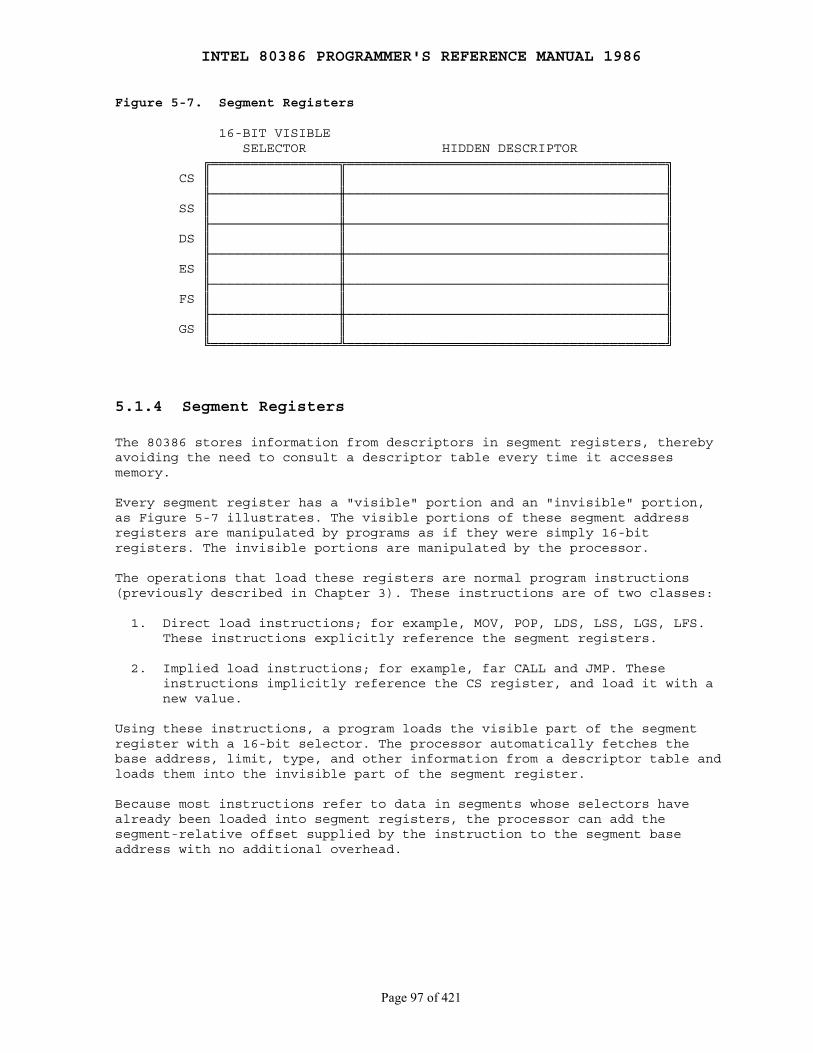
INTEL 80386 PROGRAMMER'S REFERENCE MANUAL 1986
Page 97 of 421
Figure 5-7. Segment Registers
16-BIT VISIBLE SELECTOR HIDDEN DESCRIPTOR ╔════════════════╦════════════════════════════════════════╗ CS ║ ║ ║ ╟────────────────╫────────────────────────────────────────╢ SS ║ ║ ║ ╟────────────────╫────────────────────────────────────────╢ DS ║ ║ ║ ╟────────────────╫────────────────────────────────────────╢ ES ║ ║ ║ ╟────────────────╫────────────────────────────────────────╢ FS ║ ║ ║ ╟────────────────╫────────────────────────────────────────╢ GS ║ ║ ║ ╚════════════════╩════════════════════════════════════════╝
5.1.4 Segment Registers
The 80386 stores information from descriptors in segment registers, therebyavoiding the need to consult a descriptor table every time it accessesmemory.
Every segment register has a "visible" portion and an "invisible" portion,as Figure 5-7 illustrates. The visible portions of these segment addressregisters are manipulated by programs as if they were simply 16-bitregisters. The invisible portions are manipulated by the processor.
The operations that load these registers are normal program instructions(previously described in Chapter 3). These instructions are of two classes:
1. Direct load instructions; for example, MOV, POP, LDS, LSS, LGS, LFS. These instructions explicitly reference the segment registers.
2. Implied load instructions; for example, far CALL and JMP. These instructions implicitly reference the CS register, and load it with a new value.
Using these instructions, a program loads the visible part of the segmentregister with a 16-bit selector. The processor automatically fetches thebase address, limit, type, and other information from a descriptor table andloads them into the invisible part of the segment register.
Because most instructions refer to data in segments whose selectors havealready been loaded into segment registers, the processor can add thesegment-relative offset supplied by the instruction to the segment baseaddress with no additional overhead.
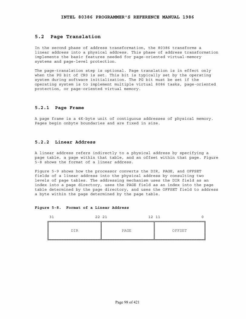
INTEL 80386 PROGRAMMER'S REFERENCE MANUAL 1986
Page 98 of 421
5.2 Page Translation
In the second phase of address transformation, the 80386 transforms alinear address into a physical address. This phase of address transformationimplements the basic features needed for page-oriented virtual-memorysystems and page-level protection.
The page-translation step is optional. Page translation is in effect onlywhen the PG bit of CR0 is set. This bit is typically set by the operatingsystem during software initialization. The PG bit must be set if theoperating system is to implement multiple virtual 8086 tasks, page-orientedprotection, or page-oriented virtual memory.
5.2.1 Page Frame
A page frame is a 4K-byte unit of contiguous addresses of physical memory.Pages begin onbyte boundaries and are fixed in size.
5.2.2 Linear Address
A linear address refers indirectly to a physical address by specifying apage table, a page within that table, and an offset within that page. Figure5-8 shows the format of a linear address.
Figure 5-9 shows how the processor converts the DIR, PAGE, and OFFSETfields of a linear address into the physical address by consulting twolevels of page tables. The addressing mechanism uses the DIR field as anindex into a page directory, uses the PAGE field as an index into the pagetable determined by the page directory, and uses the OFFSET field to addressa byte within the page determined by the page table.
Figure 5-8. Format of a Linear Address
31 22 21 12 11 0 ╔═════════════════════╦═════════════════════╦════════════════════╗ ║ ║ ║ ║ ║ DIR ║ PAGE ║ OFFSET ║ ║ ║ ║ ║ ╚═════════════════════╩═════════════════════╩════════════════════╝
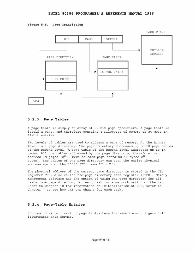
INTEL 80386 PROGRAMMER'S REFERENCE MANUAL 1986
Page 99 of 421
Figure 5-9. Page Translation
PAGE FRAME ╔═══════════╦═══════════╦══════════╗ ╔═══════════════╗ ║ DIR ║ PAGE ║ OFFSET ║ ║ ║ ╚═════╤═════╩═════╤═════╩═════╤════╝ ║ ║ │ │ │ ║ ║ ┌─────────────┘ │ └─────────────►║ PHYSICAL ║ │ │ ║ ADDRESS ║ │ PAGE DIRECTORY │ PAGE TABLE ║ ║ │ ╔═══════════════╗ │ ╔═══════════════╗ ║ ║ │ ║ ║ │ ║ ║ ╚═══════════════╝ │ ║ ║ │ ╠═══════════════╣ ▲ │ ║ ║ └──►║ PG TBL ENTRY ╟──────────────┘ │ ╠═══════════════╣ ╠═══════════════╣ └─►║ DIR ENTRY ╟──┐ ║ ║ ╠═══════════════╣ │ ║ ║ ║ ║ │ ║ ║ ╚═══════════════╝ │ ╚═══════════════╝ ▲ │ ▲╔═══════╗ │ └───────────────┘║ CR3 ╟────────┘╚═══════╝
5.2.3 Page Tables
A page table is simply an array of 32-bit page specifiers. A page table isitself a page, and therefore contains 4 Kilobytes of memory or at most 1K32-bit entries.
Two levels of tables are used to address a page of memory. At the higherlevel is a page directory. The page directory addresses up to 1K page tablesof the second level. A page table of the second level addresses up to 1Kpages. All the tables addressed by one page directory, therefore, canaddress 1M pages (220). Because each page contains 4K bytes 212
bytes), the tables of one page directory can span the entire physicaladdress space of the 80386 (220 times 212 = 232).
The physical address of the current page directory is stored in the CPUregister CR3, also called the page directory base register (PDBR). Memorymanagement software has the option of using one page directory for alltasks, one page directory for each task, or some combination of the two.Refer to Chapter 10 for information on initialization of CR3. Refer toChapter 7 to see how CR3 can change for each task.
5.2.4 Page-Table Entries
Entries in either level of page tables have the same format. Figure 5-10illustrates this format.

INTEL 80386 PROGRAMMER'S REFERENCE MANUAL 1986
Page 100 of 421
5.2.4.1 Page Frame Address
The page frame address specifies the physical starting address of a page.Because pages are located on 4K boundaries, the low-order 12 bits are alwayszero. In a page directory, the page frame address is the address of a pagetable. In a second-level page table, the page frame address is the addressof the page frame that contains the desired memory operand.
5.2.4.2 Present Bit
The Present bit indicates whether a page table entry can be used in addresstranslation. P=1 indicates that the entry can be used.
When P=0 in either level of page tables, the entry is not valid for addresstranslation, and the rest of the entry is available for software use; noneof the other bits in the entry is tested by the hardware. Figure 5-11illustrates the format of a page-table entry when P=0.
If P=0 in either level of page tables when an attempt is made to use apage-table entry for address translation, the processor signals a pageexception. In software systems that support paged virtual memory, thepage-not-present exception handler can bring the required page into physicalmemory. The instruction that caused the exception can then be reexecuted.Refer to Chapter 9 for more information on exception handlers.
Note that there is no present bit for the page directory itself. The pagedirectory may be not-present while the associated task is suspended, but theoperating system must ensure that the page directory indicated by the CR3image in the TSS is present in physical memory before the task isdispatched. Refer to Chapter 7 for an explanation of the TSS and taskdispatching.
Figure 5-10. Format of a Page Table Entry
31 12 11 0 ╔══════════════════════════════════════╤═══════╤═══╤═╤═╤═══╤═╤═╤═╗ ║ │ │ │ │ │ │U│R│ ║ ║ PAGE FRAME ADDRESS 31..12 │ AVAIL │0 0│D│A│0 0│/│/│P║ ║ │ │ │ │ │ │S│W│ ║ ╚══════════════════════════════════════╧═══════╧═══╧═╧═╧═══╧═╧═╧═╝
P - PRESENT R/W - READ/WRITE U/S - USER/SUPERVISOR D - DIRTY AVAIL - AVAILABLE FOR SYSTEMS PROGRAMMER USE
NOTE: 0 INDICATES INTEL RESERVED. DO NOT DEFINE.

INTEL 80386 PROGRAMMER'S REFERENCE MANUAL 1986
Page 101 of 421
Figure 5-11. Invalid Page Table Entry
31 1 0 ╔══════════════════════════════════════════════════════════════╤═╗ ║ │ ║ ║ AVAILABLE │0║ ║ │ ║ ╚══════════════════════════════════════════════════════════════╧═╝
5.2.4.3 Accessed and Dirty Bits
These bits provide data about page usage in both levels of the page tables.With the exception of the dirty bit in a page directory entry, these bitsare set by the hardware; however, the processor does not clear any of thesebits.
The processor sets the corresponding accessed bits in both levels of pagetables to one before a read or write operation to a page.
The processor sets the dirty bit in the second-level page table to onebefore a write to an address covered by that page table entry. The dirty bitin directory entries is undefined.
An operating system that supports paged virtual memory can use these bitsto determine what pages to eliminate from physical memory when the demandfor memory exceeds the physical memory available. The operating system isresponsible for testing and clearing these bits.
Refer to Chapter 11 for how the 80386 coordinates updates to the accessedand dirty bits in multiprocessor systems.
5.2.4.4 Read/Write and User/Supervisor Bits
These bits are not used for address translation, but are used forpage-level protection, which the processor performs at the same time asaddress translation. Refer to Chapter 6 where protection is discussed indetail.
5.2.5 Page Translation Cache
For greatest efficiency in address translation, the processor stores themost recently used page-table data in an on-chip cache. Only if thenecessary paging information is not in the cache must both levels of pagetables be referenced.
The existence of the page-translation cache is invisible to applicationsprogrammers but not to systems programmers; operating-system programmersmust flush the cache whenever the page tables are changed. Thepage-translation cache can be flushed by either of two methods:
INTEL 80386 PROGRAMMER'S REFERENCE MANUAL 1986
Page 102 of 421
1. By reloading CR3 with a MOV instruction; for example:
MOV CR3, EAX
2. By performing a task switch to a TSS that has a different CR3 image than the current TSS. (Refer to Chapter 7 for more information on task switching.)
5.3 Combining Segment and Page Translation
Figure 5-12 combines Figure 5-2 and Figure 5-9 to summarize both phasesof the transformation from a logical address to a physical address whenpaging is enabled. By appropriate choice of options and parameters to bothphases, memory-management software can implement several different styles ofmemory management.
5.3.1 "Flat" Architecture
When the 80386 is used to execute software designed for architectures thatdon't have segments, it may be expedient to effectively "turn off" thesegmentation features of the 80386. The 80386 does not have a mode thatdisables segmentation, but the same effect can be achieved by initiallyloading the segment registers with selectors for descriptors that encompassthe entire 32-bit linear address space. Once loaded, the segment registersdon't need to be changed. The 32-bit offsets used by 80386 instructions areadequate to address the entire linear-address space.
5.3.2 Segments Spanning Several Pages
The architecture of the 80386 permits segments to be larger or smaller thanthe size of a page (4 Kilobytes). For example, suppose a segment is used toaddress and protect a large data structure that spans 132 Kilobytes. In asoftware system that supports paged virtual memory, it is not necessary forthe entire structure to be in physical memory at once. The structure isdivided into 33 pages, any number of which may not be present. Theapplications programmer does not need to be aware that the virtual memorysubsystem is paging the structure in this manner.

INTEL 80386 PROGRAMMER'S REFERENCE MANUAL 1986
Page 103 of 421
Figure 5-12. 80306 Addressing Machanism
16 0 32 0 ╔════════════════════╦═════════════════════════════════════╗ LOGICAL ║ SELECTOR ║ OFFSET ║ ADDRESS ╚════╤══════════╤════╩════════════════════╤════════════════╝ ┌───────┘ ▼ │ │ DESCRIPTOR TABLE │ │ ╔═══════════════╗ │ │ ║ ║ │ │ ║ ║ │ │ ║ ║ │ │ ║ ║ │ │ ╠═══════════════╣ │ │ ║ SEGMENT ║ ╔═══╗ │ └─►║ DESCRIPTOR ╟────────►║ + ║◄──────────┘ ╠═══════════════╣ ╚═╤═╝ ║ ║ │ ╚═══════════════╝ │ ▼ PAGE FRAME LINEAR ╔═══════════╦═══════════╦══════════╗ ╔═══════════════╗ ADDRESS ║ DIR ║ PAGE ║ OFFSET ║ ║ ║ ╚═════╤═════╩═════╤═════╩═════╤════╝ ║ ║ │ │ │ ║ ║ ┌─────────────┘ │ └─────────────►║ PHYSICAL ║ │ │ ║ ADDRESS ║ │ PAGE DIRECTORY │ PAGE TABLE ║ ║ │ ╔═══════════════╗ │ ╔═══════════════╗ ║ ║ │ ║ ║ │ ║ ║ ║ ║ │ ║ ║ │ ║ ║ ╚═══════════════╝ │ ║ ║ │ ╠═══════════════╣ ▲ │ ║ ║ └──►║ PG TBL ENTRY ╟──────────────┘ │ ╠═══════════════╣ ╠═══════════════╣ └─►║ DIR ENTRY ╟──┐ ║ ║ ╠═══════════════╣ │ ║ ║ ║ ║ │ ║ ║ ╚═══════════════╝ │ ╚═══════════════╝ ▲ │ ▲╔═══════╗ │ └───────────────┘║ CR3 ╟────────┘╚═══════╝
5.3.3 Pages Spanning Several Segments
On the other hand, segments may be smaller than the size of a page. Forexample, consider a small data structure such as a semaphore. Because of theprotection and sharing provided by segments (refer to Chapter 6), it may beuseful to create a separate segment for each semaphore. But, because asystem may need many semaphores, it is not efficient to allocate a page foreach. Therefore, it may be useful to cluster many related segments within apage.
INTEL 80386 PROGRAMMER'S REFERENCE MANUAL 1986
Page 104 of 421
5.3.4 Non-Aligned Page and Segment Boundaries
The architecture of the 80386 does not enforce any correspondence betweenthe boundaries of pages and segments. It is perfectly permissible for a pageto contain the end of one segment and the beginning of another. Likewise, asegment may contain the end of one page and the beginning of another.
5.3.5 Aligned Page and Segment Boundaries
Memory-management software may be simpler, however, if it enforces somecorrespondence between page and segment boundaries. For example, if segmentsare allocated only in units of one page, the logic for segment and pageallocation can be combined. There is no need for logic to account forpartially used pages.
5.3.6 Page-Table per Segment
An approach to space management that provides even further simplificationof space-management software is to maintain a one-to-one correspondencebetween segment descriptors and page-directory entries, as Figure 5-13illustrates. Each descriptor has a base address in which the low-order 22bits are zero; in other words, the base address is mapped by the first entryof a page table. A segment may have any limit from 1 to 4 megabytes.Depending on the limit, the segment is contained in from 1 to 1K pageframes. A task is thus limited to 1K segments (a sufficient number for manyapplications), each containing up to 4 Mbytes. The descriptor, thecorresponding page-directory entry, and the corresponding page table can beallocated and deallocated simultaneously.

INTEL 80386 PROGRAMMER'S REFERENCE MANUAL 1986
Page 105 of 421
Figure 5-13. Descriptor per Page Table
PAGE FRAMES ╔═══════════╗ LDT PAGE DIRECTORY PAGE TABLES ║ ║ ╔══════════╗ ╔══════════╗ ╔══════════╗ ║ ║ ║ ║ ║ ║ ║ ║ ┌─►╚═══════════╝ ╠══════════╣ ╠══════════╣ ╠══════════╣ │ ║ ║ ║ ║ ║ PTE ╟───┘ ╔═══════════╗ ╠══════════╣ ╠══════════╣ ╠══════════╣ ║ ║ ║ ║ ║ ║ ║ PTE ╟───┐ ║ ║ ╠══════════╣ ╠══════════╣ ╠══════════╣ └─►╚═══════════╝ ║ ║ ║ ║ ║ PTE ╟───┐ ╠══════════╣ ╠══════════╣ ┌───►╚══════════╝ │ ╔═══════════╗ ║DESCRIPTOR╟──────►║ PDE ╟───┘ │ ║ ║ ╠══════════╣ ╠══════════╣ │ ║ ║ ║DESCRIPTOR╟──────►║ PDE ╟───┐ └─►╚═══════════╝ ╠══════════╣ ╠══════════╣ │ ╔══════════╗ ║ ║ ║ ║ │ ║ ║ ╔═══════════╗ ╠══════════╣ ╠══════════╣ │ ╠══════════╣ ║ ║ ║ ║ ║ ║ │ ║ ║ ║ ║ ╠══════════╣ ╠══════════╣ │ ╠══════════╣ ┌─►╚═══════════╝ ║ ║ ║ ║ │ ║ PTE ╟───┘ ╠══════════╣ ╠══════════╣ │ ╠══════════╣ ╔═══════════╗ ║ ║ ║ ║ │ ║ PTE ╟───┐ ║ ║ ╚══════════╝ ╚══════════╝ └───►╚══════════╝ │ ║ ║ LDT PAGE DIRECTORY PAGE TABLES └─►╚═══════════╝ PAGE FRAMES
INTEL 80386 PROGRAMMER'S REFERENCE MANUAL 1986
Page 106 of 421
Chapter 6 Protection
────────────────────────────────────────────────────────────────────────────
6.1 Why Protection?
The purpose of the protection features of the 80386 is to help detect andidentify bugs. The 80386 supports sophisticated applications that mayconsist of hundreds or thousands of program modules. In such applications,the question is how bugs can be found and eliminated as quickly as possibleand how their damage can be tightly confined. To help debug applicationsfaster and make them more robust in production, the 80386 containsmechanisms to verify memory accesses and instruction execution forconformance to protection criteria. These mechanisms may be used or ignored,according to system design objectives.
6.2 Overview of 80386 Protection Mechanisms
Protection in the 80386 has five aspects:
1. Type checking 2. Limit checking 3. Restriction of addressable domain 4. Restriction of procedure entry points 5. Restriction of instruction set
The protection hardware of the 80386 is an integral part of the memorymanagement hardware. Protection applies both to segment translation and topage translation.
Each reference to memory is checked by the hardware to verify that itsatisfies the protection criteria. All these checks are made before thememory cycle is started; any violation prevents that cycle from starting andresults in an exception. Since the checks are performed concurrently withaddress formation, there is no performance penalty.
Invalid attempts to access memory result in an exception. Refer toChapter 9 for an explanation of the exception mechanism. The presentchapter defines the protection violations that lead to exceptions.
The concept of "privilege" is central to several aspects of protection(numbers 3, 4, and 5 in the preceeding list). Applied to procedures,privilege is the degree to which the procedure can be trusted not to make amistake that might affect other procedures or data. Applied to data,privilege is the degree of protection that a data structure should havefrom less trusted procedures.
The concept of privilege applies both to segment protection and to pageprotection.
INTEL 80386 PROGRAMMER'S REFERENCE MANUAL 1986
Page 107 of 421
6.3 Segment-Level Protection
All five aspects of protection apply to segment translation:
1. Type checking 2. Limit checking 3. Restriction of addressable domain 4. Restriction of procedure entry points 5. Restriction of instruction set
The segment is the unit of protection, and segment descriptors storeprotection parameters. Protection checks are performed automatically by theCPU when the selector of a segment descriptor is loaded into a segmentregister and with every segment access. Segment registers hold theprotection parameters of the currently addressable segments.
6.3.1 Descriptors Store Protection Parameters
Figure 6-1 highlights the protection-related fields of segment descriptors.
The protection parameters are placed in the descriptor by systems softwareat the time a descriptor is created. In general, applications programmers donot need to be concerned about protection parameters.
When a program loads a selector into a segment register, the processorloads not only the base address of the segment but also protectioninformation. Each segment register has bits in the invisible portion forstoring base, limit, type, and privilege level; therefore, subsequentprotection checks on the same segment do not consume additional clockcycles.
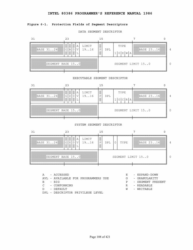
INTEL 80386 PROGRAMMER'S REFERENCE MANUAL 1986
Page 108 of 421
Figure 6-1. Protection Fields of Segment Descriptors
DATA SEGMENT DESCRIPTOR
31 23 15 7 0 ╔═════════════════╪═╤═╤═╤═╤═════════╪═╤═════╤═════════╪═════════════════╗ ║▒▒▒▒▒▒▒▒▒▒▒▒▒▒▒▒▒│▒│▒│▒│A│ LIMIT │▒│ │ TYPE │▒▒▒▒▒▒▒▒▒▒▒▒▒▒▒▒▒║ ║▒▒▒BASE 31..24▒▒▒│G│B│0│V│ 19..16 │P│ DPL │ │▒▒▒BASE 23..16▒▒▒║ 4 ║▒▒▒▒▒▒▒▒▒▒▒▒▒▒▒▒▒│▒│▒│▒│L│ │▒│ │1│0│E│W│A│▒▒▒▒▒▒▒▒▒▒▒▒▒▒▒▒▒║ ╟─────────────────┴─┴─┴─┴─┴─────────┼─┴─────┴─┴─┴─┴─┴─┴─────────────────╢ ║▒▒▒▒▒▒▒▒▒▒▒▒▒▒▒▒▒▒▒▒▒▒▒▒▒▒▒▒▒▒▒▒▒▒▒│ ║ ║▒▒▒▒▒▒▒▒SEGMENT BASE 15..0▒▒▒▒▒▒▒▒▒│ SEGMENT LIMIT 15..0 ║ 0 ║▒▒▒▒▒▒▒▒▒▒▒▒▒▒▒▒▒▒▒▒▒▒▒▒▒▒▒▒▒▒▒▒▒▒▒│ ║ ╚═════════════════╪═════════════════╪═════════════════╪═════════════════╝
EXECUTABLE SEGMENT DESCRIPTOR
31 23 15 7 0 ╔═════════════════╪═╤═╤═╤═╤═════════╪═╤═════╤═════════╪═════════════════╗ ║▒▒▒▒▒▒▒▒▒▒▒▒▒▒▒▒▒│▒│▒│▒│A│ LIMIT │▒│ │ TYPE │▒▒▒▒▒▒▒▒▒▒▒▒▒▒▒▒▒║ ║▒▒▒BASE 31..24▒▒▒│G│D│0│V│ 19..16 │P│ DPL │ │▒▒▒BASE 23..16▒▒▒║ 4 ║▒▒▒▒▒▒▒▒▒▒▒▒▒▒▒▒▒│▒│▒│▒│L│ │▒│ │1│0│C│R│A│▒▒▒▒▒▒▒▒▒▒▒▒▒▒▒▒▒║ ╟─────────────────┴─┴─┴─┴─┴─────────┼─┴─────┴─┴─┴─┴─┴─┴─────────────────╢ ║▒▒▒▒▒▒▒▒▒▒▒▒▒▒▒▒▒▒▒▒▒▒▒▒▒▒▒▒▒▒▒▒▒▒▒│ ║ ║▒▒▒▒▒▒▒▒SEGMENT BASE 15..0▒▒▒▒▒▒▒▒▒│ SEGMENT LIMIT 15..0 ║ 0 ║▒▒▒▒▒▒▒▒▒▒▒▒▒▒▒▒▒▒▒▒▒▒▒▒▒▒▒▒▒▒▒▒▒▒▒│ ║ ╚═════════════════╪═════════════════╪═════════════════╪═════════════════╝
SYSTEM SEGMENT DESCRIPTOR
31 23 15 7 0 ╔═════════════════╪═╤═╤═╤═╤═════════╪═╤═════╤═╤═══════╪═════════════════╗ ║▒▒▒▒▒▒▒▒▒▒▒▒▒▒▒▒▒│▒│▒│▒│A│ LIMIT │▒│ │ │ │▒▒▒▒▒▒▒▒▒▒▒▒▒▒▒▒▒║ ║▒▒▒BASE 31..24▒▒▒│G│X│0│V│ 19..16 │P│ DPL │0│ TYPE │▒▒▒BASE 23..16▒▒▒║ 4 ║▒▒▒▒▒▒▒▒▒▒▒▒▒▒▒▒▒│▒│▒│▒│L│ │▒│ │ │ │▒▒▒▒▒▒▒▒▒▒▒▒▒▒▒▒▒║ ╟─────────────────┴─┴─┴─┴─┴─────────┼─┴─────┴─┴───────┴─────────────────╢ ║▒▒▒▒▒▒▒▒▒▒▒▒▒▒▒▒▒▒▒▒▒▒▒▒▒▒▒▒▒▒▒▒▒▒▒│ ║ ║▒▒▒▒▒▒▒▒SEGMENT BASE 15..0▒▒▒▒▒▒▒▒▒│ SEGMENT LIMIT 15..0 ║ 0 ║▒▒▒▒▒▒▒▒▒▒▒▒▒▒▒▒▒▒▒▒▒▒▒▒▒▒▒▒▒▒▒▒▒▒▒│ ║ ╚═════════════════╪═════════════════╪═════════════════╪═════════════════╝
A - ACCESSED E - EXPAND-DOWN AVL - AVAILABLE FOR PROGRAMMERS USE G - GRANULARITY B - BIG P - SEGMENT PRESENT C - CONFORMING R - READABLE D - DEFAULT W - WRITABLE DPL - DESCRIPTOR PRIVILEGE LEVEL

INTEL 80386 PROGRAMMER'S REFERENCE MANUAL 1986
Page 109 of 421
6.3.1.1 Type Checking
The TYPE field of a descriptor has two functions:
1. It distinguishes among different descriptor formats. 2. It specifies the intended usage of a segment.
Besides the descriptors for data and executable segments commonly used byapplications programs, the 80386 has descriptors for special segments usedby the operating system and for gates. Table 6-1 lists all the types definedfor system segments and gates. Note that not all descriptors definesegments; gate descriptors have a different purpose that is discussed laterin this chapter.
The type fields of data and executable segment descriptors include bitswhich further define the purpose of the segment (refer to Figure 6-1):
● The writable bit in a data-segment descriptor specifies whether instructions can write into the segment.
● The readable bit in an executable-segment descriptor specifies whether instructions are allowed to read from the segment (for example, to access constants that are stored with instructions). A readable, executable segment may be read in two ways:
1. Via the CS register, by using a CS override prefix.
2. By loading a selector of the descriptor into a data-segment register (DS, ES, FS,or GS).
Type checking can be used to detect programming errors that would attemptto use segments in ways not intended by the programmer. The processorexamines type information on two kinds of occasions:
1. When a selector of a descriptor is loaded into a segment register. Certain segment registers can contain only certain descriptor types; for example:
● The CS register can be loaded only with a selector of an executable segment.
● Selectors of executable segments that are not readable cannot be loaded into data-segment registers.
● Only selectors of writable data segments can be loaded into SS.
2. When an instruction refers (implicitly or explicitly) to a segment register. Certain segments can be used by instructions only in certain predefined ways; for example:
● No instruction may write into an executable segment.
● No instruction may write into a data segment if the writable bit is not set.
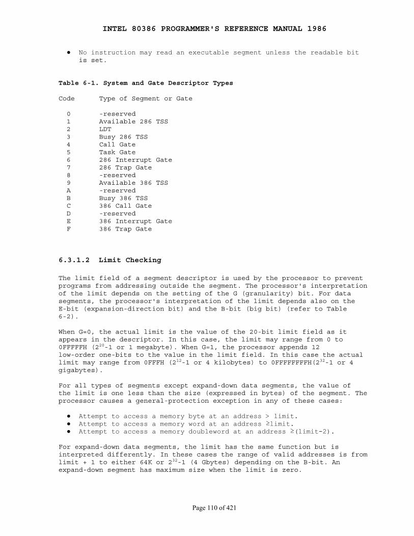
INTEL 80386 PROGRAMMER'S REFERENCE MANUAL 1986
Page 110 of 421
● No instruction may read an executable segment unless the readable bit is set.
Table 6-1. System and Gate Descriptor Types
Code Type of Segment or Gate
0 -reserved 1 Available 286 TSS 2 LDT 3 Busy 286 TSS 4 Call Gate 5 Task Gate 6 286 Interrupt Gate 7 286 Trap Gate 8 -reserved 9 Available 386 TSS A -reserved B Busy 386 TSS C 386 Call Gate D -reserved E 386 Interrupt Gate F 386 Trap Gate
6.3.1.2 Limit Checking
The limit field of a segment descriptor is used by the processor to preventprograms from addressing outside the segment. The processor's interpretationof the limit depends on the setting of the G (granularity) bit. For datasegments, the processor's interpretation of the limit depends also on theE-bit (expansion-direction bit) and the B-bit (big bit) (refer to Table6-2).
When G=0, the actual limit is the value of the 20-bit limit field as itappears in the descriptor. In this case, the limit may range from 0 to0FFFFFH (220-1 or 1 megabyte). When G=1, the processor appends 12low-order one-bits to the value in the limit field. In this case the actuallimit may range from 0FFFH (212-1 or 4 kilobytes) to 0FFFFFFFFH(232-1 or 4gigabytes).
For all types of segments except expand-down data segments, the value ofthe limit is one less than the size (expressed in bytes) of the segment. Theprocessor causes a general-protection exception in any of these cases:
● Attempt to access a memory byte at an address > limit. ● Attempt to access a memory word at an address ≥limit. ● Attempt to access a memory doubleword at an address ≥(limit-2).
For expand-down data segments, the limit has the same function but isinterpreted differently. In these cases the range of valid addresses is fromlimit + 1 to either 64K or 232-1 (4 Gbytes) depending on the B-bit. Anexpand-down segment has maximum size when the limit is zero.
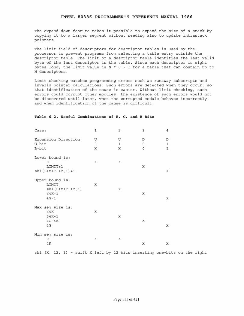
INTEL 80386 PROGRAMMER'S REFERENCE MANUAL 1986
Page 111 of 421
The expand-down feature makes it possible to expand the size of a stack bycopying it to a larger segment without needing also to update intrastackpointers.
The limit field of descriptors for descriptor tables is used by theprocessor to prevent programs from selecting a table entry outside thedescriptor table. The limit of a descriptor table identifies the last validbyte of the last descriptor in the table. Since each descriptor is eightbytes long, the limit value is N * 8 - 1 for a table that can contain up toN descriptors.
Limit checking catches programming errors such as runaway subscripts andinvalid pointer calculations. Such errors are detected when they occur, sothat identification of the cause is easier. Without limit checking, sucherrors could corrupt other modules; the existence of such errors would notbe discovered until later, when the corrupted module behaves incorrectly,and when identification of the cause is difficult.
Table 6-2. Useful Combinations of E, G, and B Bits
Case: 1 2 3 4
Expansion Direction U U D DG-bit 0 1 0 1B-bit X X 0 1
Lower bound is: 0 X X LIMIT+1 Xshl(LIMIT,12,1)+1 X
Upper bound is: LIMIT X shl(LIMIT,12,1) X 64K-1 X 4G-1 X
Max seg size is: 64K X 64K-1 X 4G-4K X 4G X
Min seg size is: 0 X X 4K X X
shl (X, 12, 1) = shift X left by 12 bits inserting one-bits on the right
INTEL 80386 PROGRAMMER'S REFERENCE MANUAL 1986
Page 112 of 421
6.3.1.3 Privilege Levels
The concept of privilege is implemented by assigning a value from zero tothree to key objects recognized by the processor. This value is called theprivilege level. The value zero represents the greatest privilege, thevalue three represents the least privilege. The followingprocessor-recognized objects contain privilege levels:
● Descriptors contain a field called the descriptor privilege level (DPL).
● Selectors contain a field called the requestor's privilege level (RPL). The RPL is intended to represent the privilege level of the procedure that originates a selector.
● An internal processor register records the current privilege level (CPL). Normally the CPL is equal to the DPL of the segment that the processor is currently executing. CPL changes as control is transferred to segments with differing DPLs.
The processor automatically evaluates the right of a procedure to accessanother segment by comparing the CPL to one or more other privilege levels.The evaluation is performed at the time the selector of a descriptor isloaded into a segment register. The criteria used for evaluating access todata differs from that for evaluating transfers of control to executablesegments; therefore, the two types of access are considered separately inthe following sections.
Figure 6-2 shows how these levels of privilege can be interpreted as ringsof protection. The center is for the segments containing the most criticalsoftware, usually the kernel of the operating system. Outer rings are forthe segments of less critical software.
It is not necessary to use all four privilege levels. Existing softwarethat was designed to use only one or two levels of privilege can simplyignore the other levels offered by the 80386. A one-level system should useprivilege level zero; a two-level system should use privilege levels zeroand three.
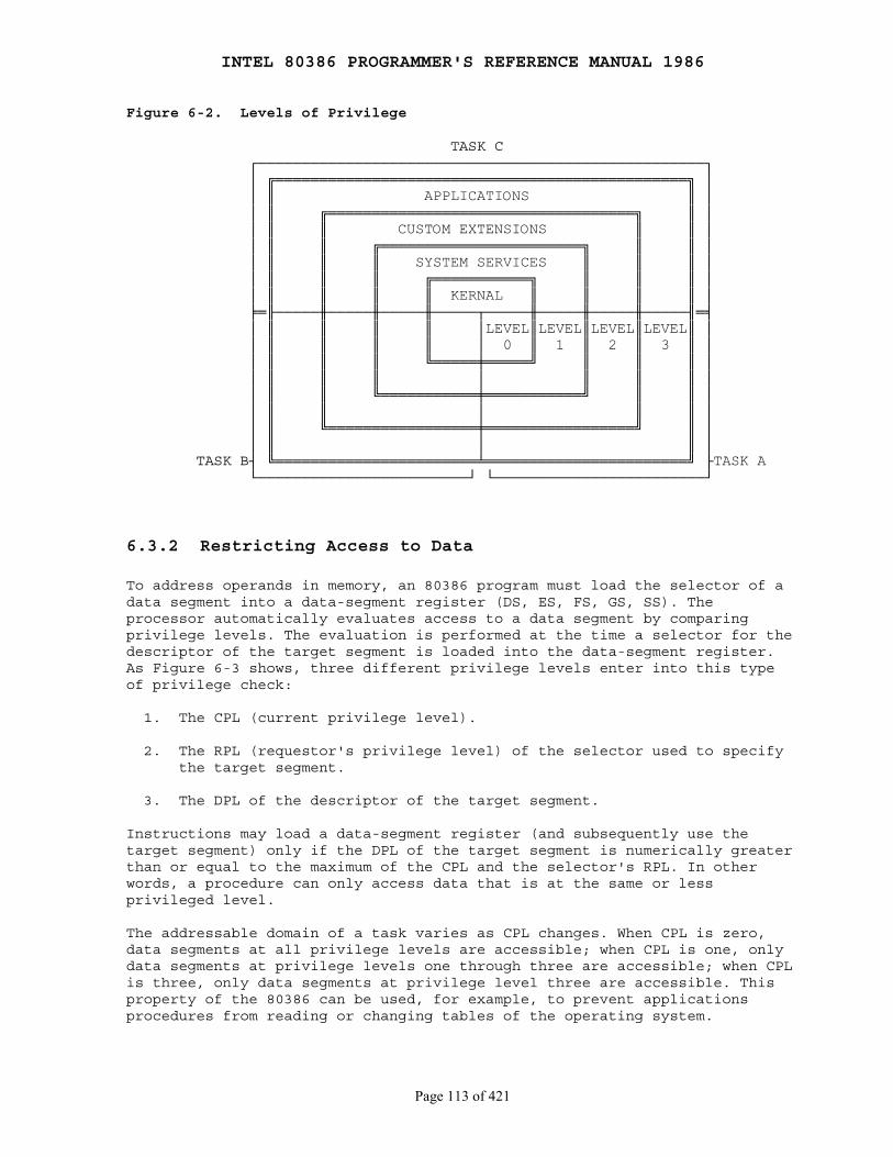
INTEL 80386 PROGRAMMER'S REFERENCE MANUAL 1986
Page 113 of 421
Figure 6-2. Levels of Privilege
TASK C ┌───────────────────────────────────────────────────┐ │ ╔═══════════════════════════════════════════════╗ │ │ ║ APPLICATIONS ║ │ │ ║ ╔═══════════════════════════════════╗ ║ │ │ ║ ║ CUSTOM EXTENSIONS ║ ║ │ │ ║ ║ ╔═══════════════════════╗ ║ ║ │ │ ║ ║ ║ SYSTEM SERVICES ║ ║ ║ │ │ ║ ║ ║ ╔═══════════╗ ║ ║ ║ │ │ ║ ║ ║ ║ KERNAL ║ ║ ║ ║ │ ╞═╟─────╫─────╫─────╫─────┬─────╫─────╫─────╫─────╢═╡ │ ║ ║ ║ ║ │LEVEL║LEVEL║LEVEL║LEVEL║ │ │ ║ ║ ║ ║ │ 0 ║ 1 ║ 2 ║ 3 ║ │ │ ║ ║ ║ ╚═════╪═════╝ ║ ║ ║ │ │ ║ ║ ║ │ ║ ║ ║ │ │ ║ ║ ╚═══════════╪═══════════╝ ║ ║ │ │ ║ ║ │ ║ ║ │ │ ║ ╚═════════════════╪═════════════════╝ ║ │ │ ║ │ ║ │ TASK B┤ ╚═══════════════════════╧═══════════════════════╝ ├TASK A └────────────────────────┘ └────────────────────────┘
6.3.2 Restricting Access to Data
To address operands in memory, an 80386 program must load the selector of adata segment into a data-segment register (DS, ES, FS, GS, SS). Theprocessor automatically evaluates access to a data segment by comparingprivilege levels. The evaluation is performed at the time a selector for thedescriptor of the target segment is loaded into the data-segment register.As Figure 6-3 shows, three different privilege levels enter into this typeof privilege check:
1. The CPL (current privilege level).
2. The RPL (requestor's privilege level) of the selector used to specify the target segment.
3. The DPL of the descriptor of the target segment.
Instructions may load a data-segment register (and subsequently use thetarget segment) only if the DPL of the target segment is numerically greaterthan or equal to the maximum of the CPL and the selector's RPL. In otherwords, a procedure can only access data that is at the same or lessprivileged level.
The addressable domain of a task varies as CPL changes. When CPL is zero,data segments at all privilege levels are accessible; when CPL is one, onlydata segments at privilege levels one through three are accessible; when CPLis three, only data segments at privilege level three are accessible. Thisproperty of the 80386 can be used, for example, to prevent applicationsprocedures from reading or changing tables of the operating system.
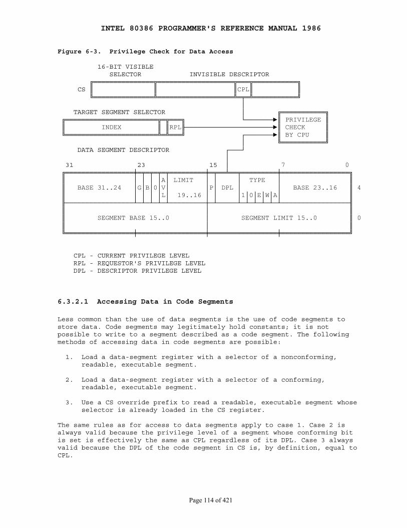
INTEL 80386 PROGRAMMER'S REFERENCE MANUAL 1986
Page 114 of 421
Figure 6-3. Privilege Check for Data Access
16-BIT VISIBLE SELECTOR INVISIBLE DESCRIPTOR ╔═══════════════╦═══════════════════╦═══╦═══════════╗ CS ║ ║ ║CPL║ ║ ╚═══════════════╩═══════════════════╩═╤═╩═══════════╝ │ TARGET SEGMENT SELECTOR │ ╔═══════════╗ ╔═══════════════════════╦═╦═══╗ └───────►║ PRIVILEGE ║ ║ INDEX ║ ║RPL╟──────────────────────►║ CHECK ║ ╚═══════════════════════╩═╩═══╝ ┌───────►║ BY CPU ║ │ ╚═══════════╝ DATA SEGMENT DESCRIPTOR ┌───┘ │ 31 23 15 │ 7 0 ╔═════════════════╪═╤═╤═╤═╤═════════╪═╤══╧══╤═════════╪═════════════════╗ ║ │ │ │ │A│ LIMIT │ │ │ TYPE │ ║ ║ BASE 31..24 │G│B│0│V│ │P│ DPL │ │ BASE 23..16 ║ 4 ║ │ │ │ │L│ 19..16 │ │ │1│0│E│W│A│ ║ ╟─────────────────┴─┴─┴─┴─┴─────────┼─┴─────┴─┴─┴─┴─┴─┴─────────────────╢ ║ │ ║ ║ SEGMENT BASE 15..0 │ SEGMENT LIMIT 15..0 ║ 0 ║ │ ║ ╚═════════════════╪═════════════════╪═════════════════╪═════════════════╝
CPL - CURRENT PRIVILEGE LEVEL RPL - REQUESTOR'S PRIVILEGE LEVEL DPL - DESCRIPTOR PRIVILEGE LEVEL
6.3.2.1 Accessing Data in Code Segments
Less common than the use of data segments is the use of code segments tostore data. Code segments may legitimately hold constants; it is notpossible to write to a segment described as a code segment. The followingmethods of accessing data in code segments are possible:
1. Load a data-segment register with a selector of a nonconforming, readable, executable segment.
2. Load a data-segment register with a selector of a conforming, readable, executable segment.
3. Use a CS override prefix to read a readable, executable segment whose selector is already loaded in the CS register.
The same rules as for access to data segments apply to case 1. Case 2 isalways valid because the privilege level of a segment whose conforming bitis set is effectively the same as CPL regardless of its DPL. Case 3 alwaysvalid because the DPL of the code segment in CS is, by definition, equal toCPL.
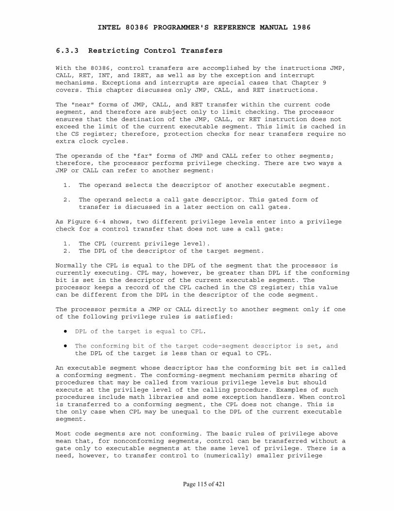
INTEL 80386 PROGRAMMER'S REFERENCE MANUAL 1986
Page 115 of 421
6.3.3 Restricting Control Transfers
With the 80386, control transfers are accomplished by the instructions JMP,CALL, RET, INT, and IRET, as well as by the exception and interruptmechanisms. Exceptions and interrupts are special cases that Chapter 9covers. This chapter discusses only JMP, CALL, and RET instructions.
The "near" forms of JMP, CALL, and RET transfer within the current codesegment, and therefore are subject only to limit checking. The processorensures that the destination of the JMP, CALL, or RET instruction does notexceed the limit of the current executable segment. This limit is cached inthe CS register; therefore, protection checks for near transfers require noextra clock cycles.
The operands of the "far" forms of JMP and CALL refer to other segments;therefore, the processor performs privilege checking. There are two ways aJMP or CALL can refer to another segment:
1. The operand selects the descriptor of another executable segment.
2. The operand selects a call gate descriptor. This gated form of transfer is discussed in a later section on call gates.
As Figure 6-4 shows, two different privilege levels enter into a privilegecheck for a control transfer that does not use a call gate:
1. The CPL (current privilege level). 2. The DPL of the descriptor of the target segment.
Normally the CPL is equal to the DPL of the segment that the processor iscurrently executing. CPL may, however, be greater than DPL if the conformingbit is set in the descriptor of the current executable segment. Theprocessor keeps a record of the CPL cached in the CS register; this valuecan be different from the DPL in the descriptor of the code segment.
The processor permits a JMP or CALL directly to another segment only if oneof the following privilege rules is satisfied:
● DPL of the target is equal to CPL.
● The conforming bit of the target code-segment descriptor is set, and the DPL of the target is less than or equal to CPL.
An executable segment whose descriptor has the conforming bit set is calleda conforming segment. The conforming-segment mechanism permits sharing ofprocedures that may be called from various privilege levels but shouldexecute at the privilege level of the calling procedure. Examples of suchprocedures include math libraries and some exception handlers. When controlis transferred to a conforming segment, the CPL does not change. This isthe only case when CPL may be unequal to the DPL of the current executablesegment.
Most code segments are not conforming. The basic rules of privilege abovemean that, for nonconforming segments, control can be transferred without agate only to executable segments at the same level of privilege. There is aneed, however, to transfer control to (numerically) smaller privilege
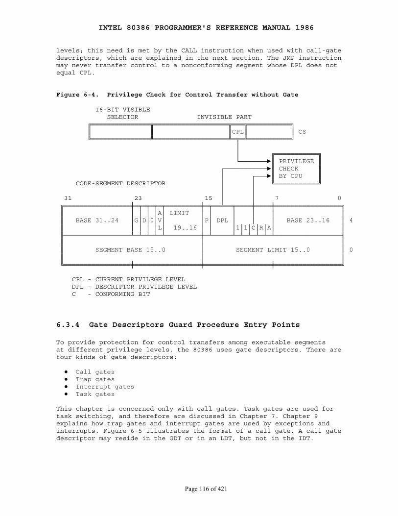
INTEL 80386 PROGRAMMER'S REFERENCE MANUAL 1986
Page 116 of 421
levels; this need is met by the CALL instruction when used with call-gatedescriptors, which are explained in the next section. The JMP instructionmay never transfer control to a nonconforming segment whose DPL does notequal CPL.
Figure 6-4. Privilege Check for Control Transfer without Gate
16-BIT VISIBLE SELECTOR INVISIBLE PART ╔═══════════════╦═══════════════════╦═══╦═══════════╗ ║ ║ ║CPL║ ║ CS ╚═══════════════╩═══════════════════╩═╤═╩═══════════╝ │ │ ╔═══════════╗ └───────►║ PRIVILEGE ║ ┌───────────►║ CHECK ║ │ ┌───►║ BY CPU ║ CODE-SEGMENT DESCRIPTOR │ │ ╚═══════════╝ │ │ 31 23 15 │ │ 7 0 ╔═════════════════╪═╤═╤═╤═╤═════════╪═╤══╧══╤════╪════╪═════════════════╗ ║ │ │ │ │A│ LIMIT │ │ │ │ │ ║ ║ BASE 31..24 │G│D│0│V│ │P│ DPL │ │ │ BASE 23..16 ║ 4 ║ │ │ │ │L│ 19..16 │ │ │1│1│C│R│A│ ║ ╟─────────────────┴─┴─┴─┴─┴─────────┼─┴─────┴─┴─┴─┴─┴─┴─────────────────╢ ║ │ ║ ║ SEGMENT BASE 15..0 │ SEGMENT LIMIT 15..0 ║ 0 ║ │ ║ ╚═════════════════╪═════════════════╪═════════════════╪═════════════════╝
CPL - CURRENT PRIVILEGE LEVEL DPL - DESCRIPTOR PRIVILEGE LEVEL C - CONFORMING BIT
6.3.4 Gate Descriptors Guard Procedure Entry Points
To provide protection for control transfers among executable segmentsat different privilege levels, the 80386 uses gate descriptors. There arefour kinds of gate descriptors:
● Call gates ● Trap gates ● Interrupt gates ● Task gates
This chapter is concerned only with call gates. Task gates are used fortask switching, and therefore are discussed in Chapter 7. Chapter 9explains how trap gates and interrupt gates are used by exceptions andinterrupts. Figure 6-5 illustrates the format of a call gate. A call gatedescriptor may reside in the GDT or in an LDT, but not in the IDT.
INTEL 80386 PROGRAMMER'S REFERENCE MANUAL 1986
Page 117 of 421
A call gate has two primary functions:
1. To define an entry point of a procedure. 2. To specify the privilege level of the entry point.
Call gate descriptors are used by call and jump instructions in the samemanner as code segment descriptors. When the hardware recognizes that thedestination selector refers to a gate descriptor, the operation of theinstruction is expanded as determined by the contents of the call gate.
The selector and offset fields of a gate form a pointer to the entry pointof a procedure. A call gate guarantees that all transitions to anothersegment go to a valid entry point, rather than possibly into the middle of aprocedure (or worse, into the middle of an instruction). The far pointeroperand of the control transfer instruction does not point to the segmentand offset of the target instruction; rather, the selector part of thepointer selects a gate, and the offset is not used. Figure 6-6 illustratesthis style of addressing.
As Figure 6-7 shows, four different privilege levels are used to check thevalidity of a control transfer via a call gate:
1. The CPL (current privilege level).
2. The RPL (requestor's privilege level) of the selector used to specify the call gate.
3. The DPL of the gate descriptor.
4. The DPL of the descriptor of the target executable segment.
The DPL field of the gate descriptor determines what privilege levels canuse the gate. One code segment can have several procedures that are intendedfor use by different privilege levels. For example, an operating system mayhave some services that are intended to be used by applications, whereasothers may be intended only for use by other systems software.
Gates can be used for control transfers to numerically smaller privilegelevels or to the same privilege level (though they are not necessary fortransfers to the same level). Only CALL instructions can use gates totransfer to smaller privilege levels. A gate may be used by a JMPinstruction only to transfer to an executable segment with the sameprivilege level or to a conforming segment.
For a JMP instruction to a nonconforming segment, both of the followingprivilege rules must be satisfied; otherwise, a general protection exceptionresults.
MAX (CPL,RPL) ≤ gate DPL target segment DPL = CPL
For a CALL instruction (or for a JMP instruction to a conforming segment),both of the following privilege rules must be satisfied; otherwise, ageneral protection exception results.
MAX (CPL,RPL) ≤ gate DPL target segment DPL ≤ CPL
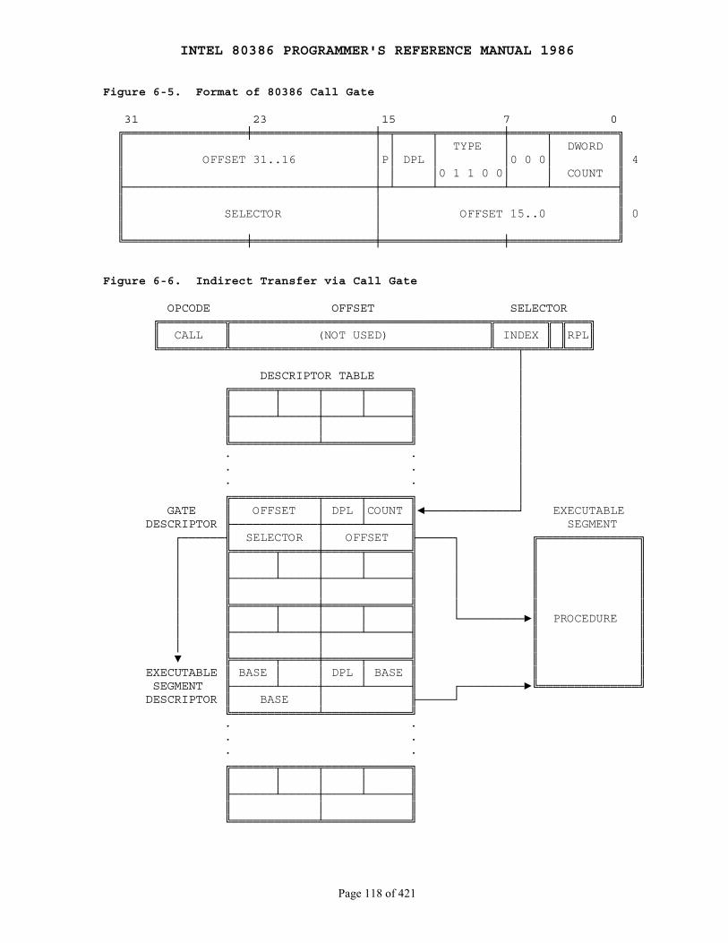
INTEL 80386 PROGRAMMER'S REFERENCE MANUAL 1986
Page 118 of 421
Figure 6-5. Format of 80386 Call Gate
31 23 15 7 0 ╔═════════════════╪═════════════════╪═╤═════╤═════════╪═════╤═════════╗ ║ │ │ │ TYPE │ │ DWORD ║ ║ OFFSET 31..16 │P│ DPL │ │0 0 0│ ║ 4 ║ │ │ │0 1 1 0 0│ │ COUNT ║ ╟───────────────────────────────────┼─┴─────┴─────────┴─────┴─────────╢ ║ │ ║ ║ SELECTOR │ OFFSET 15..0 ║ 0 ║ │ ║ ╚═════════════════╪═════════════════╪═════════════════╪═══════════════╝
Figure 6-6. Indirect Transfer via Call Gate
OPCODE OFFSET SELECTOR ╔═════════╦════════════════════════════════════╦═══════╦═╦═══╗ ║ CALL ║ (NOT USED) ║ INDEX ║ ║RPL║ ╚═════════╩════════════════════════════════════╩═══╤═══╩═╩═══╝ │ DESCRIPTOR TABLE │ ╔══════╤═════╤═════╤══════╗ │ ║ │ │ │ ║ │ ╟──────┴─────┼─────┴──────╢ │ ║ │ ║ │ ╚════════════╧════════════╝ │ · · │ · · │ · · │ ╔════════════╤═════╤══════╗ │ GATE ║ OFFSET │ DPL │COUNT ║◄─────────────┘ EXECUTABLE DESCRIPTOR ╟────────────┼─────┴──────╢ SEGMENT ┌──────╢ SELECTOR │ OFFSET ╟─────┐ ╔══════════════╗ │ ╠══════╤═════╪═════╤══════╣ │ ║ ║ │ ║ │ │ │ ║ │ ║ ║ │ ╟──────┴─────┼─────┴──────╢ │ ║ ║ │ ║ │ ║ │ ║ ║ │ ╠══════╤═════╪═════╤══════╣ │ ║ ║ │ ║ │ │ │ ║ └─────────►║ PROCEDURE ║ │ ╟──────┴─────┼─────┴──────╢ ║ ║ │ ║ │ ║ ║ ║ ▼ ╠══════╤═════╪═════╤══════╣ ║ ║ EXECUTABLE ║ BASE │ │ DPL │ BASE ║ ║ ║ SEGMENT ╟──────┴─────┼─────┴──────╢ ┌─────────►╚══════════════╝ DESCRIPTOR ║ BASE │ ╟─────┘ ╚════════════╧════════════╝ · · · · · · ╔══════╤═════╤═════╤══════╗ ║ │ │ │ ║ ╟──────┴─────┼─────┴──────╢ ║ │ ║ ╚════════════╧════════════╝
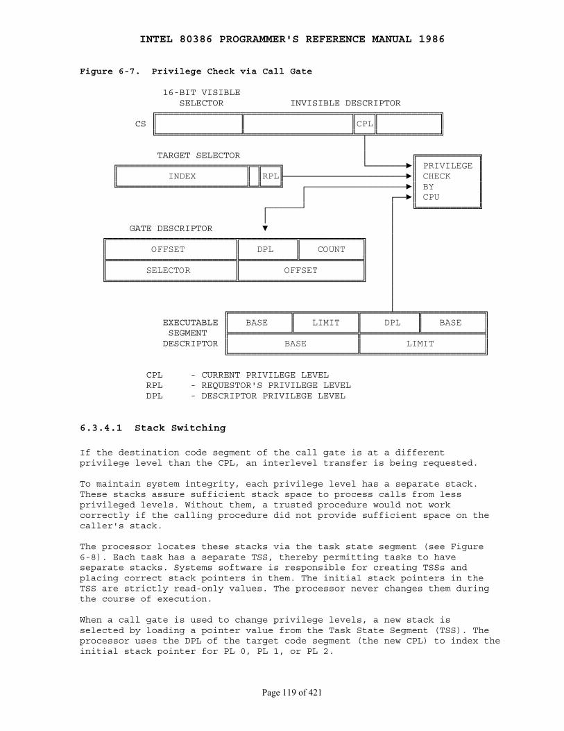
INTEL 80386 PROGRAMMER'S REFERENCE MANUAL 1986
Page 119 of 421
Figure 6-7. Privilege Check via Call Gate
16-BIT VISIBLE SELECTOR INVISIBLE DESCRIPTOR ╔═══════════════╦═══════════════════╦═══╦═══════════╗ CS ║ ║ ║CPL║ ║ ╚═══════════════╩═══════════════════╩═╤═╩═══════════╝ │ TARGET SELECTOR │ ╔═══════════╗ ╔═══════════════════════╦═╦═══╗ └───────►║ PRIVILEGE ║ ║ INDEX ║ ║RPL╟──────────────────────►║ CHECK ║ ╚═══════════════════════╩═╩═══╝ ┌──────────────────►║ BY ║ │ ┌──►║ CPU ║ ┌──────┘ │ ╚═══════════╝ │ │ GATE DESCRIPTOR ▼ │ ╔═══════════════════════╦══════════╦═══════════╗ │ ║ OFFSET ║ DPL ║ COUNT ║ │ ╠═══════════════════════╬══════════╩═══════════╣ │ ║ SELECTOR ║ OFFSET ║ │ ╚═══════════════════════╩══════════════════════╝ │ │ │ ╔═══════════╦═══════════╦═════╧════╦═══════════╗ EXECUTABLE ║ BASE ║ LIMIT ║ DPL ║ BASE ║ SEGMENT ╠═══════════╩═══════════╬══════════╩═══════════╣ DESCRIPTOR ║ BASE ║ LIMIT ║ ╚═══════════════════════╩══════════════════════╝
CPL - CURRENT PRIVILEGE LEVEL RPL - REQUESTOR'S PRIVILEGE LEVEL DPL - DESCRIPTOR PRIVILEGE LEVEL
6.3.4.1 Stack Switching
If the destination code segment of the call gate is at a differentprivilege level than the CPL, an interlevel transfer is being requested.
To maintain system integrity, each privilege level has a separate stack.These stacks assure sufficient stack space to process calls from lessprivileged levels. Without them, a trusted procedure would not workcorrectly if the calling procedure did not provide sufficient space on thecaller's stack.
The processor locates these stacks via the task state segment (see Figure6-8). Each task has a separate TSS, thereby permitting tasks to haveseparate stacks. Systems software is responsible for creating TSSs andplacing correct stack pointers in them. The initial stack pointers in theTSS are strictly read-only values. The processor never changes them duringthe course of execution.
When a call gate is used to change privilege levels, a new stack isselected by loading a pointer value from the Task State Segment (TSS). Theprocessor uses the DPL of the target code segment (the new CPL) to index theinitial stack pointer for PL 0, PL 1, or PL 2.

INTEL 80386 PROGRAMMER'S REFERENCE MANUAL 1986
Page 120 of 421
The DPL of the new stack data segment must equal the new CPL; if it doesnot, a stack exception occurs. It is the responsibility of systems softwareto create stacks and stack-segment descriptors for all privilege levels thatare used. Each stack must contain enough space to hold the old SS:ESP, thereturn address, and all parameters and local variables that may be requiredto process a call.
As with intralevel calls, parameters for the subroutine are placed on thestack. To make privilege transitions transparent to the called procedure,the processor copies the parameters to the new stack. The count field of acall gate tells the processor how many doublewords (up to 31) to copy fromthe caller's stack to the new stack. If the count is zero, no parameters arecopied.
The processor performs the following stack-related steps in executing aninterlevel CALL.
1. The new stack is checked to assure that it is large enough to hold the parameters and linkages; if it is not, a stack fault occurs with an error code of 0.
2. The old value of the stack registers SS:ESP is pushed onto the new stack as two doublewords.
3. The parameters are copied.
4. A pointer to the instruction after the CALL instruction (the former value of CS:EIP) is pushed onto the new stack. The final value of SS:ESP points to this return pointer on the new stack.
Figure 6-9 illustrates the stack contents after a successful interlevelcall.
The TSS does not have a stack pointer for a privilege level 3 stack,because privilege level 3 cannot be called by any procedure at any otherprivilege level.
Procedures that may be called from another privilege level and that requiremore than the 31 doublewords for parameters must use the saved SS:ESP linkto access all parameters beyond the last doubleword copied.
A call via a call gate does not check the values of the words copied ontothe new stack. The called procedure should check each parameter forvalidity. A later section discusses how the ARPL, VERR, VERW, LSL, and LARinstructions can be used to check pointer values.

INTEL 80386 PROGRAMMER'S REFERENCE MANUAL 1986
Page 121 of 421
Figure 6-8. Initial Stack Pointers of TSS
31 23 15 7 0 ╔════════╪════════╪════════╪════════╗64 · · · · · · ║ ║ ╠════════╪════════╪════════╪════════╣ ║ EFLAGS ║24 ╠════════╪════════╪════════╪════════╣ ║ INSTRUCTION POINTER (EIP) ║20 ╠════════╪════════╪════════╪════════╣ ║ CR3 (PDBR) ║1C ╠════════╪════════╦════════╪═════╦══╣ ─┐ ║00000000 00000000║ SS2 ║10║18 │ ╠════════╪════════╩════════╪═════╩══╣ │ ║ ESP2 ║14 │ ╠════════╪════════╦════════╪═════╦══╣ │ ║00000000 00000000║ SS1 ║01║10 │ INITIAL ╠════════╪════════╩════════╪═════╩══╣ ├─ STACK ║ ESP1 ║0C │ POINTERS ╠════════╪════════╦════════╪═════╦══╣ │ ║00000000 00000000║ SS0 ║00║8 │ ╠════════╪════════╩════════╪═════╩══╣ │ ║ ESP0 ║4 │ ╠════════╪════════╦════════╪════════╣ ─┘ ║00000000 00000000║ TSS BACK LINK ║0 ╚════════╪════════╩════════╪════════╝
Figure 6-9. Stack Contents after an Interlevel Call
31 0 SS:ESP ╔═══════╪═══════╗◄──FROM TSS 31 0 ║▒▒▒▒▒▒▒│OLD SS ║ ╔═══════╪═══════╗ ╠═══════╪═══════╣ D O ║ ║ ║ OLD ESP ║ I F ║ ║ ╠═══════╪═══════╣ R ║ ║ ║ PARM 3 ║ E E ║ ║ ╠═══════╪═══════╣ C X ║ ║ ║ PARM 2 ║ T P ╠═══════╪═══════╣ ╠═══════╪═══════╣ I A ║ PARM 3 ║ ║ PARM 1 ║ O N ╠═══════╪═══════╣ ╠═══════╪═══════╣ N S ║ PARM 2 ║ ║▒▒▒▒▒▒▒│OLD CS ║ NEW I ╠═══════╪═══════╣ OLD ╠═══════╪═══════╣ SS:ESP │ O ║ PARM 1 ║ SS:ESP ║ OLD EIP ║ │ │ N ╠═══════╪═══════╣◄───┘ ╠═══════╪═══════╣◄─────┘ │ ║ ║ ║ ║ ▼ ║ ║ ║ ║ ╚═══════╪═══════╝ ╚═══════╪═══════╝ OLD STACK NEW STACK
INTEL 80386 PROGRAMMER'S REFERENCE MANUAL 1986
Page 122 of 421
6.3.4.2 Returning from a Procedure
The "near" forms of the RET instruction transfer control within the currentcode segment and therefore are subject only to limit checking. The offset ofthe instruction following the corresponding CALL, is popped from the stack.The processor ensures that this offset does not exceed the limit of thecurrent executable segment.
The "far" form of the RET instruction pops the return pointer that waspushed onto the stack by a prior far CALL instruction. Under normalconditions, the return pointer is valid, because of its relation to theprior CALL or INT. Nevertheless, the processor performs privilege checkingbecause of the possibility that the current procedure altered the pointer orfailed to properly maintain the stack. The RPL of the CS selector poppedoff the stack by the return instruction identifies the privilege level ofthe calling procedure.
An intersegment return instruction can change privilege levels, but onlytoward procedures of lesser privilege. When the RET instruction encounters asaved CS value whose RPL is numerically greater than the CPL, an interlevelreturn occurs. Such a return follows these steps:
1. The checks shown in Table 6-3 are made, and CS:EIP and SS:ESP are loaded with their former values that were saved on the stack.
2. The old SS:ESP (from the top of the current stack) value is adjusted by the number of bytes indicated in the RET instruction. The resulting ESP value is not compared to the limit of the stack segment. If ESP is beyond the limit, that fact is not recognized until the next stack operation. (The SS:ESP value of the returning procedure is not preserved; normally, this value is the same as that contained in the TSS.)
3. The contents of the DS, ES, FS, and GS segment registers are checked. If any of these registers refer to segments whose DPL is greater than the new CPL (excluding conforming code segments), the segment register is loaded with the null selector (INDEX = 0, TI = 0). The RET instruction itself does not signal exceptions in these cases; however, any subsequent memory reference that attempts to use a segment register that contains the null selector will cause a general protection exception. This prevents less privileged code from accessing more privileged segments using selectors left in the segment registers by the more privileged procedure.
6.3.5 Some Instructions are Reserved for Operating System
Instructions that have the power to affect the protection mechanism or toinfluence general system performance can only be executed by trustedprocedures. The 80386 has two classes of such instructions:
1. Privileged instructions ── those used for system control.
2. Sensitive instructions ── those used for I/O and I/O related activities.

INTEL 80386 PROGRAMMER'S REFERENCE MANUAL 1986
Page 123 of 421
Table 6-3. Interlevel Return Checks
Type of Check ExceptionSF Stack FaultGP General Protection ExceptionNP Segment-Not-Present Exception Error Code
ESP is within current SS segment SF 0ESP + 7 is within current SS segment SF 0RPL of return CS is greater than CPL GP Return CSReturn CS selector is not null GP Return CSReturn CS segment is within descriptortable limit GP Return CSReturn CS descriptor is a code segment GP Return CSReturn CS segment is present NP Return CSDPL of return nonconforming codesegment = RPL of return CS, or DPL ofreturn conforming code segment ≤ RPLof return CS GP Return CSESP + N + 15 is within SS segmentN Immediate Operand of RET N Instruction SF Return SSSS selector at ESP + N + 12 is not null GP Return SSSS selector at ESP + N + 12 is withindescriptor table limit GP Return SSSS descriptor is writable data segment GP Return SSSS segment is present SF Return SSSaved SS segment DPL = RPL of savedCS GP Return SSSaved SS selector RPL = Saved SSsegment DPL GP Return SS
6.3.5.1 Privileged Instructions
The instructions that affect system data structures can only be executedwhen CPL is zero. If the CPU encounters one of these instructions when CPLis greater than zero, it signals a general protection exception. Theseinstructions include:
CLTS ── Clear Task─Switched Flag HLT ── Halt Processor LGDT ── Load GDL Register LIDT ── Load IDT Register LLDT ── Load LDT Register LMSW ── Load Machine Status Word LTR ── Load Task Register MOV to/from CRn ── Move to Control Register n MOV to /from DRn ── Move to Debug Register n MOV to/from TRn ── Move to Test Register n

INTEL 80386 PROGRAMMER'S REFERENCE MANUAL 1986
Page 124 of 421
6.3.5.2 Sensitive Instructions
Instructions that deal with I/O need to be restricted but also need to beexecuted by procedures executing at privilege levels other than zero. Themechanisms for restriction of I/O operations are covered in detail inChapter 8, "Input/Output".
6.3.6 Instructions for Pointer Validation
Pointer validation is an important part of locating programming errors.Pointer validation is necessary for maintaining isolation between theprivilege levels. Pointer validation consists of the following steps:
1. Check if the supplier of the pointer is entitled to access the segment.
2. Check if the segment type is appropriate to its intended use.
3. Check if the pointer violates the segment limit.
Although the 80386 processor automatically performs checks 2 and 3 duringinstruction execution, software must assist in performing the first check.The unprivileged instruction ARPL is provided for this purpose. Software canalso explicitly perform steps 2 and 3 to check for potential violations(rather than waiting for an exception). The unprivileged instructions LAR,LSL, VERR, and VERW are provided for this purpose.
LAR (Load Access Rights) is used to verify that a pointer refers to asegment of the proper privilege level and type. LAR has one operand──aselector for a descriptor whose access rights are to be examined. Thedescriptor must be visible at the privilege level which is the maximum ofthe CPL and the selector's RPL. If the descriptor is visible, LAR obtains amasked form of the second doubleword of the descriptor, masks this valuewith 00FxFF00H, stores the result into the specified 32-bit destinationregister, and sets the zero flag. (The x indicates that the correspondingfour bits of the stored value are undefined.) Once loaded, the access-rightsbits can be tested. All valid descriptor types can be tested by the LARinstruction. If the RPL or CPL is greater than DPL, or if the selector isoutside the table limit, no access-rights value is returned, and the zeroflag is cleared. Conforming code segments may be accessed from any privilegelevel.
LSL (Load Segment Limit) allows software to test the limit of a descriptor.If the descriptor denoted by the given selector (in memory or a register) isvisible at the CPL, LSL loads the specified 32-bit register with a 32-bit,byte granular, unscrambled limit that is calculated from fragmented limitfields and the G-bit of that descriptor. This can only be done for segments(data, code, task state, and local descriptor tables); gate descriptors areinaccessible. (Table 6-4 lists in detail which types are valid and whichare not.) Interpreting the limit is a function of the segment type. Forexample, downward expandable data segments treat the limit differently thancode segments do. For both LAR and LSL, the zero flag (ZF) is set if theloading was performed; otherwise, the ZF is cleared.

INTEL 80386 PROGRAMMER'S REFERENCE MANUAL 1986
Page 125 of 421
Table 6-4. Valid Descriptor Types for LSL
Type Descriptor Type Valid? Code
0 (invalid) NO 1 Available 286 TSS YES 2 LDT YES 3 Busy 286 TSS YES 4 286 Call Gate NO 5 Task Gate NO 6 286 Trap Gate NO 7 286 Interrupt Gate NO 8 (invalid) NO 9 Available 386 TSS YES A (invalid) NO B Busy 386 TSS YES C 386 Call Gate NO D (invalid) NO E 386 Trap Gate NO F 386 Interrupt Gate NO
6.3.6.1 Descriptor Validation
The 80386 has two instructions, VERR and VERW, which determine whether aselector points to a segment that can be read or written at the currentprivilege level. Neither instruction causes a protection fault if the resultis negative.
VERR (Verify for Reading) verifies a segment for reading and loads ZF with1 if that segment is readable from the current privilege level. VERR checksthat:
● The selector points to a descriptor within the bounds of the GDT or LDT.
● It denotes a code or data segment descriptor.
● The segment is readable and of appropriate privilege level.
The privilege check for data segments and nonconforming code segments isthat the DPL must be numerically greater than or equal to both the CPL andthe selector's RPL. Conforming segments are not checked for privilege level.
VERW (Verify for Writing) provides the same capability as VERR forverifying writability. Like the VERR instruction, VERW loads ZF if theresult of the writability check is positive. The instruction checks that thedescriptor is within bounds, is a segment descriptor, is writable, and thatits DPL is numerically greater or equal to both the CPL and the selector'sRPL. Code segments are never writable, conforming or not.
INTEL 80386 PROGRAMMER'S REFERENCE MANUAL 1986
Page 126 of 421
6.3.6.2 Pointer Integrity and RPL
The Requestor's Privilege Level (RPL) feature can prevent inappropriate useof pointers that could corrupt the operation of more privileged code or datafrom a less privileged level.
A common example is a file system procedure, FREAD (file_id, n_bytes,buffer_ptr). This hypothetical procedure reads data from a file into abuffer, overwriting whatever is there. Normally, FREAD would be available atthe user level, supplying only pointers to the file system procedures anddata located and operating at a privileged level. Normally, such a procedureprevents user-level procedures from directly changing the file tables.However, in the absence of a standard protocol for checking pointervalidity, a user-level procedure could supply a pointer into the file tablesin place of its buffer pointer, causing the FREAD procedure to corrupt themunwittingly.
Use of RPL can avoid such problems. The RPL field allows a privilegeattribute to be assigned to a selector. This privilege attribute wouldnormally indicate the privilege level of the code which generated theselector. The 80386 processor automatically checks the RPL of any selectorloaded into a segment register to determine whether the RPL allows access.
To take advantage of the processor's checking of RPL, the called procedureneed only ensure that all selectors passed to it have an RPL at least ashigh (numerically) as the original caller's CPL. This action guarantees thatselectors are not more trusted than their supplier. If one of the selectorsis used to access a segment that the caller would not be able to accessdirectly, i.e., the RPL is numerically greater than the DPL, then aprotection fault will result when that selector is loaded into a segmentregister.
ARPL (Adjust Requestor's Privilege Level) adjusts the RPL field of aselector to become the larger of its original value and the value of the RPLfield in a specified register. The latter is normally loaded from the imageof the caller's CS register which is on the stack. If the adjustment changesthe selector's RPL, ZF (the zero flag) is set; otherwise, ZF is cleared.
6.4 Page-Level Protection
Two kinds of protection are related to pages:
1. Restriction of addressable domain. 2. Type checking.
6.4.1 Page-Table Entries Hold Protection Parameters
Figure 6-10 highlights the fields of PDEs and PTEs that control access topages.
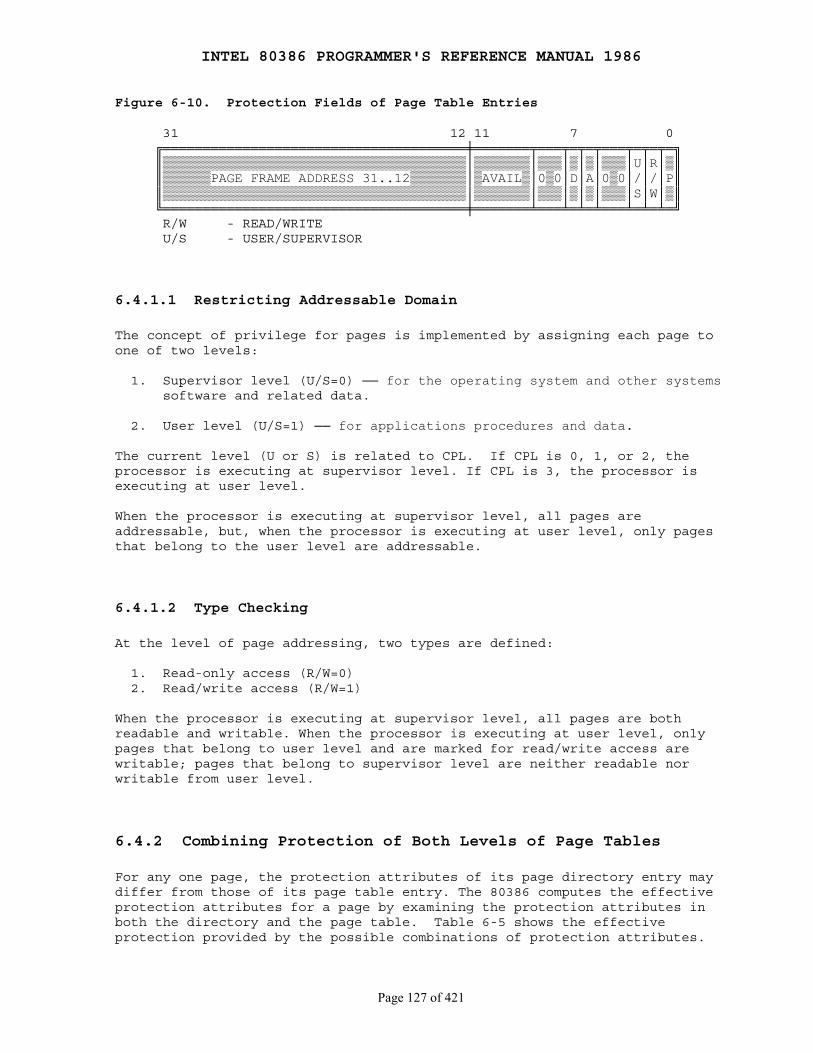
INTEL 80386 PROGRAMMER'S REFERENCE MANUAL 1986
Page 127 of 421
Figure 6-10. Protection Fields of Page Table Entries
31 12 11 7 0 ╔══════════════════════════════════════╪═══════╤═══╤═╤═╤═══╤═╤═╤═╗ ║▒▒▒▒▒▒▒▒▒▒▒▒▒▒▒▒▒▒▒▒▒▒▒▒▒▒▒▒▒▒▒▒▒▒▒▒▒▒│▒▒▒▒▒▒▒│▒▒▒│▒│▒│▒▒▒│U│R│▒║ ║▒▒▒▒▒▒PAGE FRAME ADDRESS 31..12▒▒▒▒▒▒▒│▒AVAIL▒│0▒0│D│A│0▒0│/│/│P║ ║▒▒▒▒▒▒▒▒▒▒▒▒▒▒▒▒▒▒▒▒▒▒▒▒▒▒▒▒▒▒▒▒▒▒▒▒▒▒│▒▒▒▒▒▒▒│▒▒▒│▒│▒│▒▒▒│S│W│▒║ ╚══════════════════════════════════════╪═══════╧═══╧═╧═╧═══╧═╧═╧═╝ R/W - READ/WRITE U/S - USER/SUPERVISOR
6.4.1.1 Restricting Addressable Domain
The concept of privilege for pages is implemented by assigning each page toone of two levels:
1. Supervisor level (U/S=0) ── for the operating system and other systems software and related data.
2. User level (U/S=1) ── for applications procedures and data.
The current level (U or S) is related to CPL. If CPL is 0, 1, or 2, theprocessor is executing at supervisor level. If CPL is 3, the processor isexecuting at user level.
When the processor is executing at supervisor level, all pages areaddressable, but, when the processor is executing at user level, only pagesthat belong to the user level are addressable.
6.4.1.2 Type Checking
At the level of page addressing, two types are defined:
1. Read-only access (R/W=0) 2. Read/write access (R/W=1)
When the processor is executing at supervisor level, all pages are bothreadable and writable. When the processor is executing at user level, onlypages that belong to user level and are marked for read/write access arewritable; pages that belong to supervisor level are neither readable norwritable from user level.
6.4.2 Combining Protection of Both Levels of Page Tables
For any one page, the protection attributes of its page directory entry maydiffer from those of its page table entry. The 80386 computes the effectiveprotection attributes for a page by examining the protection attributes inboth the directory and the page table. Table 6-5 shows the effectiveprotection provided by the possible combinations of protection attributes.
INTEL 80386 PROGRAMMER'S REFERENCE MANUAL 1986
Page 128 of 421
6.4.3 Overrides to Page Protection
Certain accesses are checked as if they are privilege-level 0 references,even if CPL = 3:
● LDT, GDT, TSS, IDT references. ● Access to inner stack during ring-crossing CALL/INT.
6.5 Combining Page and Segment Protection
When paging is enabled, the 80386 first evaluates segment protection, thenevaluates page protection. If the processor detects a protection violationat either the segment or the page level, the requested operation cannotproceed; a protection exception occurs instead.
For example, it is possible to define a large data segment which has somesubunits that are read-only and other subunits that are read-write. In thiscase, the page directory (or page table) entries for the read-only subunitswould have the U/S and R/W bits set to x0, indicating no write rights forall the pages described by that directory entry (or for individual pages).This technique might be used, for example, in a UNIX-like system to definea large data segment, part of which is read only (for shared data or ROMmedconstants). This enables UNIX-like systems to define a "flat" data space asone large segment, use "flat" pointers to address within this "flat" space,yet be able to protect shared data, shared files mapped into the virtualspace, and supervisor areas.
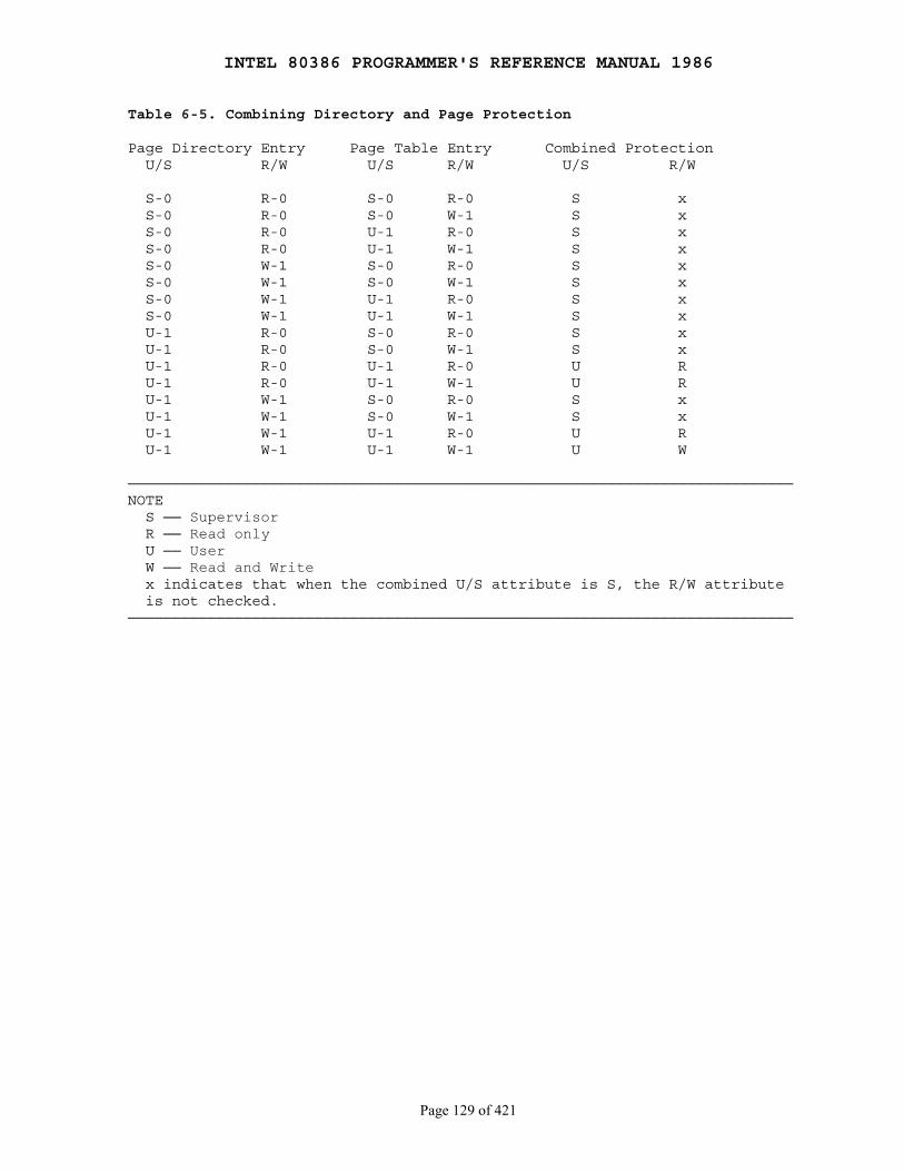
INTEL 80386 PROGRAMMER'S REFERENCE MANUAL 1986
Page 129 of 421
Table 6-5. Combining Directory and Page Protection
Page Directory Entry Page Table Entry Combined Protection U/S R/W U/S R/W U/S R/W
S-0 R-0 S-0 R-0 S x S-0 R-0 S-0 W-1 S x S-0 R-0 U-1 R-0 S x S-0 R-0 U-1 W-1 S x S-0 W-1 S-0 R-0 S x S-0 W-1 S-0 W-1 S x S-0 W-1 U-1 R-0 S x S-0 W-1 U-1 W-1 S x U-1 R-0 S-0 R-0 S x U-1 R-0 S-0 W-1 S x U-1 R-0 U-1 R-0 U R U-1 R-0 U-1 W-1 U R U-1 W-1 S-0 R-0 S x U-1 W-1 S-0 W-1 S x U-1 W-1 U-1 R-0 U R U-1 W-1 U-1 W-1 U W
───────────────────────────────────────────────────────────────────────────NOTE S ── Supervisor R ── Read only U ── User W ── Read and Write x indicates that when the combined U/S attribute is S, the R/W attribute is not checked.───────────────────────────────────────────────────────────────────────────

INTEL 80386 PROGRAMMER'S REFERENCE MANUAL 1986
Page 130 of 421
Chapter 7 Multitasking
────────────────────────────────────────────────────────────────────────────
To provide efficient, protected multitasking, the 80386 employs severalspecial data structures. It does not, however, use special instructions tocontrol multitasking; instead, it interprets ordinary control-transferinstructions differently when they refer to the special data structures. Theregisters and data structures that support multitasking are:
● Task state segment ● Task state segment descriptor ● Task register ● Task gate descriptor
With these structures the 80386 can rapidly switch execution from one taskto another, saving the context of the original task so that the task can berestarted later. In addition to the simple task switch, the 80386 offers twoother task-management features:
1. Interrupts and exceptions can cause task switches (if needed in the system design). The processor not only switches automatically to the task that handles the interrupt or exception, but it automatically switches back to the interrupted task when the interrupt or exception has been serviced. Interrupt tasks may interrupt lower-priority interrupt tasks to any depth.
2. With each switch to another task, the 80386 can also switch to another LDT and to another page directory. Thus each task can have a different logical-to-linear mapping and a different linear-to-physical mapping. This is yet another protection feature, because tasks can be isolated and prevented from interfering with one another.
7.1 Task State Segment
All the information the processor needs in order to manage a task is storedin a special type of segment, a task state segment (TSS). Figure 7-1 showsthe format of a TSS for executing 80386 tasks. (Another format is used forexecuting 80286 tasks; refer to Chapter 13.)
The fields of a TSS belong to two classes:
1. A dynamic set that the processor updates with each switch from the task. This set includes the fields that store:
● The general registers (EAX, ECX, EDX, EBX, ESP, EBP, ESI, EDI).
● The segment registers (ES, CS, SS, DS, FS, GS).
● The flags register (EFLAGS).
● The instruction pointer (EIP).
INTEL 80386 PROGRAMMER'S REFERENCE MANUAL 1986
Page 131 of 421
● The selector of the TSS of the previously executing task (updated only when a return is expected).
2. A static set that the processor reads but does not change. This set includes the fields that store:
● The selector of the task's LDT.
● The register (PDBR) that contains the base address of the task's page directory (read only when paging is enabled).
● Pointers to the stacks for privilege levels 0-2.
● The T-bit (debug trap bit) which causes the processor to raise a debug exception when a task switch occurs. (Refer to Chapter 12 for more information on debugging.)
● The I/O map base (refer to Chapter 8 for more information on the use of the I/O map).
Task state segments may reside anywhere in the linear space. The only casethat requires caution is when the TSS spans a page boundary and thehigher-addressed page is not present. In this case, the processor raises anexception if it encounters the not-present page while reading the TSS duringa task switch. Such an exception can be avoided by either of two strategies:
1. By allocating the TSS so that it does not cross a page boundary.
2. By ensuring that both pages are either both present or both not-present at the time of a task switch. If both pages are not-present, then the page-fault handler must make both pages present before restarting the instruction that caused the task switch.
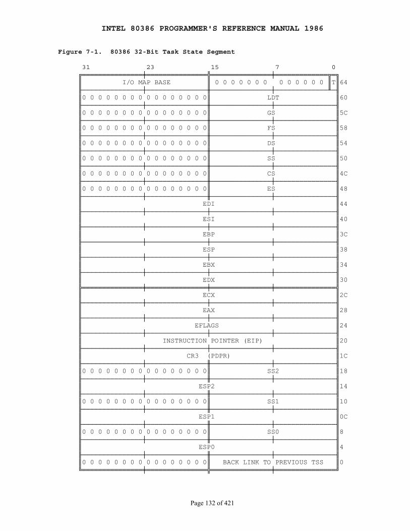
INTEL 80386 PROGRAMMER'S REFERENCE MANUAL 1986
Page 132 of 421
Figure 7-1. 80386 32-Bit Task State Segment
31 23 15 7 0 ╔═══════════════╪═══════════════╬═══════════════╪═════════════╦═╗ ║ I/O MAP BASE ║ 0 0 0 0 0 0 0 0 0 0 0 0 0 ║T║64 ╟───────────────┼───────────────╫───────────────┼─────────────╨─╢ ║0 0 0 0 0 0 0 0 0 0 0 0 0 0 0 0║ LDT ║60 ╟───────────────┼───────────────╫───────────────┼───────────────╢ ║0 0 0 0 0 0 0 0 0 0 0 0 0 0 0 0║ GS ║5C ╟───────────────┼───────────────╫───────────────┼───────────────╢ ║0 0 0 0 0 0 0 0 0 0 0 0 0 0 0 0║ FS ║58 ╟───────────────┼───────────────╫───────────────┼───────────────╢ ║0 0 0 0 0 0 0 0 0 0 0 0 0 0 0 0║ DS ║54 ╟───────────────┼───────────────╫───────────────┼───────────────╢ ║0 0 0 0 0 0 0 0 0 0 0 0 0 0 0 0║ SS ║50 ╟───────────────┼───────────────╫───────────────┼───────────────╢ ║0 0 0 0 0 0 0 0 0 0 0 0 0 0 0 0║ CS ║4C ╟───────────────┼───────────────╫───────────────┼───────────────╢ ║0 0 0 0 0 0 0 0 0 0 0 0 0 0 0 0║ ES ║48 ╟───────────────┼───────────────╫───────────────┼───────────────╢ ║ EDI ║44 ╟───────────────┼───────────────┼───────────────┼───────────────╢ ║ ESI ║40 ╟───────────────┼───────────────┼───────────────┼───────────────╢ ║ EBP ║3C ╟───────────────┼───────────────┼───────────────┼───────────────╢ ║ ESP ║38 ╟───────────────┼───────────────┼───────────────┼───────────────╢ ║ EBX ║34 ╟───────────────┼───────────────┼───────────────┼───────────────╢ ║ EDX ║30 ╠═══════════════╪═══════════════╪═══════════════╪═══════════════╣ ║ ECX ║2C ╟───────────────┼───────────────┼───────────────┼───────────────╢ ║ EAX ║28 ╟───────────────┼───────────────┼───────────────┼───────────────╢ ║ EFLAGS ║24 ╟───────────────┼───────────────┼───────────────┼───────────────╢ ║ INSTRUCTION POINTER (EIP) ║20 ╟───────────────┼───────────────┼───────────────┼───────────────╢ ║ CR3 (PDPR) ║1C ╟───────────────┼───────────────╫───────────────┼───────────────╢ ║0 0 0 0 0 0 0 0 0 0 0 0 0 0 0 0║ SS2 ║18 ╟───────────────┼───────────────╫───────────────┼───────────────╢ ║ ESP2 ║14 ╟───────────────┼───────────────╫───────────────┼───────────────╢ ║0 0 0 0 0 0 0 0 0 0 0 0 0 0 0 0║ SS1 ║10 ╟───────────────┼───────────────╫───────────────┼───────────────╢ ║ ESP1 ║0C ╟───────────────┼───────────────╫───────────────┼───────────────╢ ║0 0 0 0 0 0 0 0 0 0 0 0 0 0 0 0║ SS0 ║8 ╟───────────────┼───────────────╫───────────────┼───────────────╢ ║ ESP0 ║4 ╟───────────────┼───────────────╫───────────────┼───────────────╢ ║0 0 0 0 0 0 0 0 0 0 0 0 0 0 0 0║ BACK LINK TO PREVIOUS TSS ║0 ╚═══════════════╪═══════════════╬═══════════════╪═══════════════╝
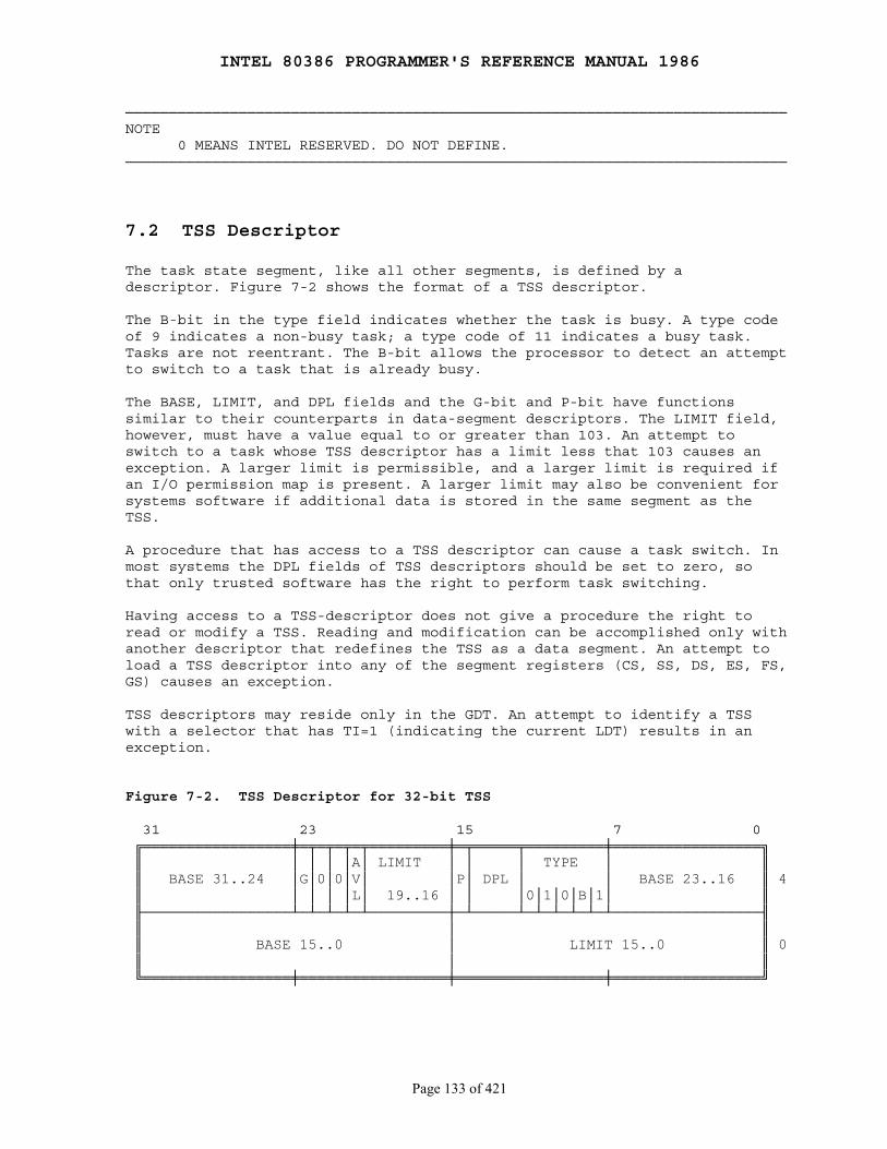
INTEL 80386 PROGRAMMER'S REFERENCE MANUAL 1986
Page 133 of 421
────────────────────────────────────────────────────────────────────────────NOTE 0 MEANS INTEL RESERVED. DO NOT DEFINE.────────────────────────────────────────────────────────────────────────────
7.2 TSS Descriptor
The task state segment, like all other segments, is defined by adescriptor. Figure 7-2 shows the format of a TSS descriptor.
The B-bit in the type field indicates whether the task is busy. A type codeof 9 indicates a non-busy task; a type code of 11 indicates a busy task.Tasks are not reentrant. The B-bit allows the processor to detect an attemptto switch to a task that is already busy.
The BASE, LIMIT, and DPL fields and the G-bit and P-bit have functionssimilar to their counterparts in data-segment descriptors. The LIMIT field,however, must have a value equal to or greater than 103. An attempt toswitch to a task whose TSS descriptor has a limit less that 103 causes anexception. A larger limit is permissible, and a larger limit is required ifan I/O permission map is present. A larger limit may also be convenient forsystems software if additional data is stored in the same segment as theTSS.
A procedure that has access to a TSS descriptor can cause a task switch. Inmost systems the DPL fields of TSS descriptors should be set to zero, sothat only trusted software has the right to perform task switching.
Having access to a TSS-descriptor does not give a procedure the right toread or modify a TSS. Reading and modification can be accomplished only withanother descriptor that redefines the TSS as a data segment. An attempt toload a TSS descriptor into any of the segment registers (CS, SS, DS, ES, FS,GS) causes an exception.
TSS descriptors may reside only in the GDT. An attempt to identify a TSSwith a selector that has TI=1 (indicating the current LDT) results in anexception.
Figure 7-2. TSS Descriptor for 32-bit TSS
31 23 15 7 0 ╔═════════════════╪═╤═╤═╤═╤═════════╪═╤═════╤═════════╪═════════════════╗ ║ │ │ │ │A│ LIMIT │ │ │ TYPE │ ║ ║ BASE 31..24 │G│0│0│V│ │P│ DPL │ │ BASE 23..16 ║ 4 ║ │ │ │ │L│ 19..16 │ │ │0│1│0│B│1│ ║ ╟─────────────────┴─┴─┴─┴─┴─────────┼─┴─────┴─┴─┴─┴─┴─┴─────────────────╢ ║ │ ║ ║ BASE 15..0 │ LIMIT 15..0 ║ 0 ║ │ ║ ╚═════════════════╪═════════════════╪═════════════════╪═════════════════╝
INTEL 80386 PROGRAMMER'S REFERENCE MANUAL 1986
Page 134 of 421
7.3 Task Register
The task register (TR) identifies the currently executing task by pointingto the TSS. Figure 7-3 shows the path by which the processor accesses thecurrent TSS.
The task register has both a "visible" portion (i.e., can be read andchanged by instructions) and an "invisible" portion (maintained by theprocessor to correspond to the visible portion; cannot be read by anyinstruction). The selector in the visible portion selects a TSS descriptorin the GDT. The processor uses the invisible portion to cache the base andlimit values from the TSS descriptor. Holding the base and limit in aregister makes execution of the task more efficient, because the processordoes not need to repeatedly fetch these values from memory when itreferences the TSS of the current task.
The instructions LTR and STR are used to modify and read the visibleportion of the task register. Both instructions take one operand, a 16-bitselector located in memory or in a general register.
LTR (Load task register) loads the visible portion of the task registerwith the selector operand, which must select a TSS descriptor in the GDT.LTR also loads the invisible portion with information from the TSSdescriptor selected by the operand. LTR is a privileged instruction; it maybe executed only when CPL is zero. LTR is generally used during systeminitialization to give an initial value to the task register; thereafter,the contents of TR are changed by task switch operations.
STR (Store task register) stores the visible portion of the task registerin a general register or memory word. STR is not privileged.

INTEL 80386 PROGRAMMER'S REFERENCE MANUAL 1986
Page 135 of 421
Figure 7-3. Task Register
╔═════════════════════════╗ ║ ║ ║ ║ ║ TASK STATE ║ ║ SEGMENT ║◄─────────┐ ║ ║ │ ║ ║ │ ╚═════════════════════════╝ │ 16-BIT VISIBLE ▲ │ REGISTER │ HIDDEN REGISTER │ ╔════════════════════╦═════════╧══════════╦═════════════╧══════╗ TR ║ SELECTOR ║ (BASE) ║ (LIMT) ║ ╚═════════╤══════════╩════════════════════╩════════════════════╝ │ ▲ ▲ │ └─────────────────┐ │ │ GLOBAL DESCRIPTOR TABLE │ │ │ ╒═════════════════════════╕ │ │ │ | TSS DESCRIPTOR | │ │ │ ╔══════╦═════╦═════╦══════╗ │ │ │ ║ ║ ║ ║ ╟───┘ │ │ ╠══════╩═════╬═════╩══════╣ │ └───────►║ ║ ╟───────┘ ╚════════════╩════════════╝ | | ╘═════════════════════════╛
7.4 Task Gate Descriptor
A task gate descriptor provides an indirect, protected reference to a TSS.Figure 7-4 illustrates the format of a task gate.
The SELECTOR field of a task gate must refer to a TSS descriptor. The valueof the RPL in this selector is not used by the processor.
The DPL field of a task gate controls the right to use the descriptor tocause a task switch. A procedure may not select a task gate descriptorunless the maximum of the selector's RPL and the CPL of the procedure isnumerically less than or equal to the DPL of the descriptor. This constraintprevents untrusted procedures from causing a task switch. (Note that when atask gate is used, the DPL of the target TSS descriptor is not used forprivilege checking.)
A procedure that has access to a task gate has the power to cause a taskswitch, just as a procedure that has access to a TSS descriptor. The 80386has task gates in addition to TSS descriptors to satisfy three needs:
1. The need for a task to have a single busy bit. Because the busy-bit is stored in the TSS descriptor, each task should have only one such descriptor. There may, however, be several task gates that select the single TSS descriptor.
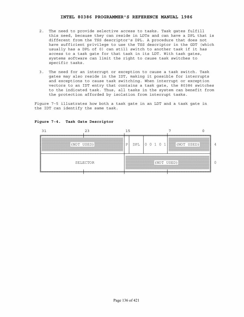
INTEL 80386 PROGRAMMER'S REFERENCE MANUAL 1986
Page 136 of 421
2. The need to provide selective access to tasks. Task gates fulfill this need, because they can reside in LDTs and can have a DPL that is different from the TSS descriptor's DPL. A procedure that does not have sufficient privilege to use the TSS descriptor in the GDT (which usually has a DPL of 0) can still switch to another task if it has access to a task gate for that task in its LDT. With task gates, systems software can limit the right to cause task switches to specific tasks.
3. The need for an interrupt or exception to cause a task switch. Task gates may also reside in the IDT, making it possible for interrupts and exceptions to cause task switching. When interrupt or exception vectors to an IDT entry that contains a task gate, the 80386 switches to the indicated task. Thus, all tasks in the system can benefit from the protection afforded by isolation from interrupt tasks.
Figure 7-5 illustrates how both a task gate in an LDT and a task gate inthe IDT can identify the same task.
Figure 7-4. Task Gate Descriptor
31 23 15 7 0 ╔═════════════════╪════════════════╪═╤═════╤═════════╪═════════════════╗ ║▒▒▒▒▒▒▒▒▒▒▒▒▒▒▒▒▒▒▒▒▒▒▒▒▒▒▒▒▒▒▒▒▒▒│ │ │ │▒▒▒▒▒▒▒▒▒▒▒▒▒▒▒▒▒║ ║▒▒▒▒▒▒▒▒▒▒▒▒(NOT USED)▒▒▒▒▒▒▒▒▒▒▒▒│P│ DPL │0 0 1 0 1│▒▒▒(NOT USED)▒▒▒▒║ 4 ║▒▒▒▒▒▒▒▒▒▒▒▒▒▒▒▒▒▒▒▒▒▒▒▒▒▒▒▒▒▒▒▒▒▒│ │ │ │▒▒▒▒▒▒▒▒▒▒▒▒▒▒▒▒▒║ ╟──────────────────────────────────┼─┴─────┴─────────┴─────────────────╢ ║ │▒▒▒▒▒▒▒▒▒▒▒▒▒▒▒▒▒▒▒▒▒▒▒▒▒▒▒▒▒▒▒▒▒▒▒║ ║ SELECTOR │▒▒▒▒▒▒▒▒▒▒▒▒(NOT USED)▒▒▒▒▒▒▒▒▒▒▒▒▒║ 0 ║ │▒▒▒▒▒▒▒▒▒▒▒▒▒▒▒▒▒▒▒▒▒▒▒▒▒▒▒▒▒▒▒▒▒▒▒║ ╚═════════════════╪════════════════╪═════════════════╪═════════════════╝

INTEL 80386 PROGRAMMER'S REFERENCE MANUAL 1986
Page 137 of 421
Figure 7-5. Task Gate Indirectly Identifies Task
LOCAL DESCRIPTOR TABLE INTERRUPT DESCRIPTOR TABLE ╒═════════════════════════╕ ╒═════════════════════════╕ | | | | | TASK GATE | | TASK GATE | ╔══════╤═════╤═════╤══════╗ ╔══════╤═════╤═════╤══════╗ ║ │ │ │ ║ ║ │ │ │ ║ ╟──────┴─────┼─────┴──────╢ ╟──────┴─────┼─────┴──────╢ ┌──╢ │ ║ ┌──╢ │ ║ │ ╚════════════╧════════════╝ │ ╚════════════╧════════════╝ │ | | │ | | │ | | │ | | │ ╘═════════════════════════╛ │ ╘═════════════════════════╛ └────────────────┐ ┌─────────────────┘ │ │ GLOBAL DESCRIPTOR TABLE │ │ ╒═════════════════════════╕ │ │ | | │ │ | TASK DESCRIPTOR | │ │ ╔══════╤═════╤═════╤══════╗ │ │ ║ │ │ │ ║ │ └─►╟──────┴─────┼─────┴──────╢ └────►║ │ ╟──┐ ╚════════════╧════════════╝ │ | | │ | | │ ╘═════════════════════════╛ │ │ ╔═════════════════════════╗ │ ║ ║ │ ║ ║ │ ║ ║ │ ║ TASK STATE ║ │ ║ SEGMENT ║ │ ║ ║ │ ║ ║ │ ║ ║ │ ╚═════════════════════════╝◄─┘
7.5 Task Switching
The 80386 switches execution to another task in any of four cases:
1. The current task executes a JMP or CALL that refers to a TSS descriptor.
2. The current task executes a JMP or CALL that refers to a task gate.
3. An interrupt or exception vectors to a task gate in the IDT.
4. The current task executes an IRET when the NT flag is set.
JMP, CALL, IRET, interrupts, and exceptions are all ordinary mechanisms ofthe 80386 that can be used in circumstances that do not require a task
INTEL 80386 PROGRAMMER'S REFERENCE MANUAL 1986
Page 138 of 421
switch. Either the type of descriptor referenced or the NT (nested task) bitin the flag word distinguishes between the standard mechanism and thevariant that causes a task switch.
To cause a task switch, a JMP or CALL instruction can refer either to a TSSdescriptor or to a task gate. The effect is the same in either case: the80386 switches to the indicated task.
An exception or interrupt causes a task switch when it vectors to a taskgate in the IDT. If it vectors to an interrupt or trap gate in the IDT, atask switch does not occur. Refer to Chapter 9 for more information on theinterrupt mechanism.
Whether invoked as a task or as a procedure of the interrupted task, aninterrupt handler always returns control to the interrupted procedure in theinterrupted task. If the NT flag is set, however, the handler is aninterrupt task, and the IRET switches back to the interrupted task.
A task switching operation involves these steps:
1. Checking that the current task is allowed to switch to the designated task. Data-access privilege rules apply in the case of JMP or CALL instructions. The DPL of the TSS descriptor or task gate must be less than or equal to the maximum of CPL and the RPL of the gate selector. Exceptions, interrupts, and IRETs are permitted to switch tasks regardless of the DPL of the target task gate or TSS descriptor.
2. Checking that the TSS descriptor of the new task is marked present and has a valid limit. Any errors up to this point occur in the context of the outgoing task. Errors are restartable and can be handled in a way that is transparent to applications procedures.
3. Saving the state of the current task. The processor finds the base address of the current TSS cached in the task register. It copies the registers into the current TSS (EAX, ECX, EDX, EBX, ESP, EBP, ESI, EDI, ES, CS, SS, DS, FS, GS, and the flag register). The EIP field of the TSS points to the instruction after the one that caused the task switch.
4. Loading the task register with the selector of the incoming task's TSS descriptor, marking the incoming task's TSS descriptor as busy, and setting the TS (task switched) bit of the MSW. The selector is either the operand of a control transfer instruction or is taken from a task gate.
5. Loading the incoming task's state from its TSS and resuming execution. The registers loaded are the LDT register; the flag register; the general registers EIP, EAX, ECX, EDX, EBX, ESP, EBP, ESI, EDI; the segment registers ES, CS, SS, DS, FS, and GS; and PDBR. Any errors detected in this step occur in the context of the incoming task. To an exception handler, it appears that the first instruction of the new task has not yet executed.
Note that the state of the outgoing task is always saved when a task switchoccurs. If execution of that task is resumed, it starts after theinstruction that caused the task switch. The registers are restored to thevalues they held when the task stopped executing.
INTEL 80386 PROGRAMMER'S REFERENCE MANUAL 1986
Page 139 of 421
Every task switch sets the TS (task switched) bit in the MSW (machinestatus word). The TS flag is useful to systems software when a coprocessor(such as a numerics coprocessor) is present. The TS bit signals that thecontext of the coprocessor may not correspond to the current 80386 task.Chapter 11 discusses the TS bit and coprocessors in more detail.
Exception handlers that field task-switch exceptions in the incoming task(exceptions due to tests 4 thru 16 of Table 7-1) should be cautious abouttaking any action that might load the selector that caused the exception.Such an action will probably cause another exception, unless the exceptionhandler first examines the selector and fixes any potential problem.
The privilege level at which execution resumes in the incoming task isneither restricted nor affected by the privilege level at which the outgoingtask was executing. Because the tasks are isolated by their separate addressspaces and TSSs and because privilege rules can be used to prevent improperaccess to a TSS, no privilege rules are needed to constrain the relationbetween the CPLs of the tasks. The new task begins executing at theprivilege level indicated by the RPL of the CS selector value that is loadedfrom the TSS.
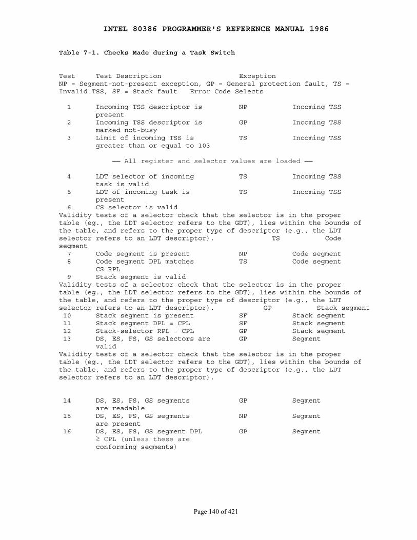
INTEL 80386 PROGRAMMER'S REFERENCE MANUAL 1986
Page 140 of 421
Table 7-1. Checks Made during a Task Switch
Test Test Description ExceptionNP = Segment-not-present exception, GP = General protection fault, TS =Invalid TSS, SF = Stack fault Error Code Selects
1 Incoming TSS descriptor is NP Incoming TSS present 2 Incoming TSS descriptor is GP Incoming TSS marked not-busy 3 Limit of incoming TSS is TS Incoming TSS greater than or equal to 103
── All register and selector values are loaded ──
4 LDT selector of incoming TS Incoming TSS task is valid 5 LDT of incoming task is TS Incoming TSS present 6 CS selector is validValidity tests of a selector check that the selector is in the propertable (eg., the LDT selector refers to the GDT), lies within the bounds ofthe table, and refers to the proper type of descriptor (e.g., the LDTselector refers to an LDT descriptor). TS Codesegment 7 Code segment is present NP Code segment 8 Code segment DPL matches TS Code segment CS RPL 9 Stack segment is validValidity tests of a selector check that the selector is in the propertable (eg., the LDT selector refers to the GDT), lies within the bounds ofthe table, and refers to the proper type of descriptor (e.g., the LDTselector refers to an LDT descriptor). GP Stack segment 10 Stack segment is present SF Stack segment 11 Stack segment DPL = CPL SF Stack segment 12 Stack-selector RPL = CPL GP Stack segment 13 DS, ES, FS, GS selectors are GP Segment validValidity tests of a selector check that the selector is in the propertable (eg., the LDT selector refers to the GDT), lies within the bounds ofthe table, and refers to the proper type of descriptor (e.g., the LDTselector refers to an LDT descriptor).
14 DS, ES, FS, GS segments GP Segment are readable 15 DS, ES, FS, GS segments NP Segment are present 16 DS, ES, FS, GS segment DPL GP Segment ≥ CPL (unless these are conforming segments)
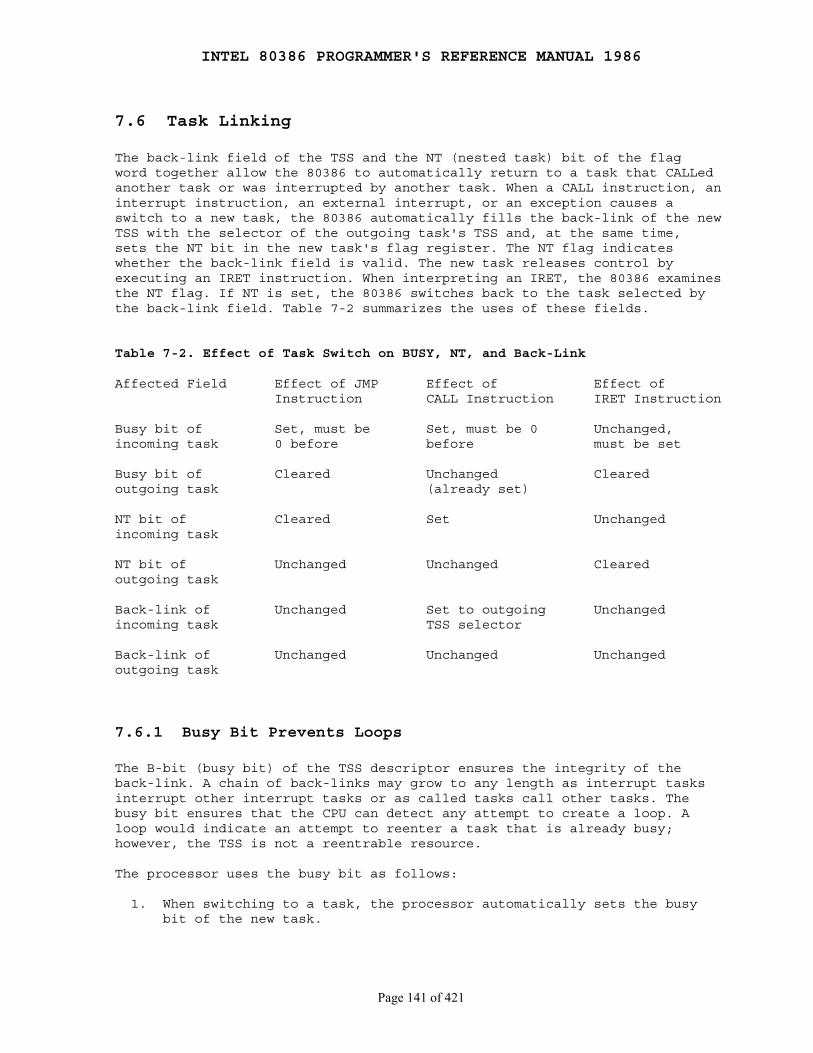
INTEL 80386 PROGRAMMER'S REFERENCE MANUAL 1986
Page 141 of 421
7.6 Task Linking
The back-link field of the TSS and the NT (nested task) bit of the flagword together allow the 80386 to automatically return to a task that CALLedanother task or was interrupted by another task. When a CALL instruction, aninterrupt instruction, an external interrupt, or an exception causes aswitch to a new task, the 80386 automatically fills the back-link of the newTSS with the selector of the outgoing task's TSS and, at the same time,sets the NT bit in the new task's flag register. The NT flag indicateswhether the back-link field is valid. The new task releases control byexecuting an IRET instruction. When interpreting an IRET, the 80386 examinesthe NT flag. If NT is set, the 80386 switches back to the task selected bythe back-link field. Table 7-2 summarizes the uses of these fields.
Table 7-2. Effect of Task Switch on BUSY, NT, and Back-Link
Affected Field Effect of JMP Effect of Effect of Instruction CALL Instruction IRET Instruction
Busy bit of Set, must be Set, must be 0 Unchanged,incoming task 0 before before must be set
Busy bit of Cleared Unchanged Clearedoutgoing task (already set)
NT bit of Cleared Set Unchangedincoming task
NT bit of Unchanged Unchanged Clearedoutgoing task
Back-link of Unchanged Set to outgoing Unchangedincoming task TSS selector
Back-link of Unchanged Unchanged Unchangedoutgoing task
7.6.1 Busy Bit Prevents Loops
The B-bit (busy bit) of the TSS descriptor ensures the integrity of theback-link. A chain of back-links may grow to any length as interrupt tasksinterrupt other interrupt tasks or as called tasks call other tasks. Thebusy bit ensures that the CPU can detect any attempt to create a loop. Aloop would indicate an attempt to reenter a task that is already busy;however, the TSS is not a reentrable resource.
The processor uses the busy bit as follows:
1. When switching to a task, the processor automatically sets the busy bit of the new task.
INTEL 80386 PROGRAMMER'S REFERENCE MANUAL 1986
Page 142 of 421
2. When switching from a task, the processor automatically clears the busy bit of the old task if that task is not to be placed on the back-link chain (i.e., the instruction causing the task switch is JMP or IRET). If the task is placed on the back-link chain, its busy bit remains set.
3. When switching to a task, the processor signals an exception if the busy bit of the new task is already set.
By these actions, the processor prevents a task from switching to itself orto any task that is on a back-link chain, thereby preventing invalid reentryinto a task.
The busy bit is effective even in multiprocessor configurations, becausethe processor automatically asserts a bus lock when it sets or clears thebusy bit. This action ensures that two processors do not invoke the sametask at the same time. (Refer to Chapter 11 for more on multiprocessing.)
7.6.2 Modifying Task Linkages
Any modification of the linkage order of tasks should be accomplished onlyby software that can be trusted to correctly update the back-link and thebusy-bit. Such changes may be needed to resume an interrupted task beforethe task that interrupted it. Trusted software that removes a task from theback-link chain must follow one of the following policies:
1. First change the back-link field in the TSS of the interrupting task, then clear the busy-bit in the TSS descriptor of the task removed from the list.
2. Ensure that no interrupts occur between updating the back-link chain and the busy bit.
7.7 Task Address Space
The LDT selector and PDBR fields of the TSS give software systems designersflexibility in utilization of segment and page mapping features of the80386. By appropriate choice of the segment and page mappings for each task,tasks may share address spaces, may have address spaces that are largelydistinct from one another, or may have any degree of sharing between thesetwo extremes.
The ability for tasks to have distinct address spaces is an importantaspect of 80386 protection. A module in one task cannot interfere with amodule in another task if the modules do not have access to the same addressspaces. The flexible memory management features of the 80386 allow systemsdesigners to assign areas of shared address space to those modules ofdifferent tasks that are designed to cooperate with each other.
INTEL 80386 PROGRAMMER'S REFERENCE MANUAL 1986
Page 143 of 421
7.7.1 Task Linear-to-Physical Space Mapping
The choices for arranging the linear-to-physical mappings of tasks fallinto two general classes:
1. One linear-to-physical mapping shared among all tasks.
When paging is not enabled, this is the only possibility. Without page tables, all linear addresses map to the same physical addresses.
When paging is enabled, this style of linear-to-physical mapping results from using one page directory for all tasks. The linear space utilized may exceed the physical space available if the operating system also implements page-level virtual memory.
2. Several partially overlapping linear-to-physical mappings.
This style is implemented by using a different page directory for each task. Because the PDBR (page directory base register) is loaded from the TSS with each task switch, each task may have a different page directory.
In theory, the linear address spaces of different tasks may map tocompletely distinct physical addresses. If the entries of different pagedirectories point to different page tables and the page tables point todifferent pages of physical memory, then the tasks do not share any physicaladdresses.
In practice, some portion of the linear address spaces of all tasks mustmap to the same physical addresses. The task state segments must lie in acommon space so that the mapping of TSS addresses does not change while theprocessor is reading and updating the TSSs during a task switch. The linearspace mapped by the GDT should also be mapped to a common physical space;otherwise, the purpose of the GDT is defeated. Figure 7-6 shows how thelinear spaces of two tasks can overlap in the physical space by sharingpage tables.
7.7.2 Task Logical Address Space
By itself, a common linear-to-physical space mapping does not enablesharing of data among tasks. To share data, tasks must also have a commonlogical-to-linear space mapping; i.e., they must also have access todescriptors that point into a shared linear address space. There are threeways to create common logical-to-physical address-space mappings:
1. Via the GDT. All tasks have access to the descriptors in the GDT. If those descriptors point into a linear-address space that is mapped to a common physical-address space for all tasks, then the tasks can share data and instructions.
2. By sharing LDTs. Two or more tasks can use the same LDT if the LDT selectors in their TSSs select the same LDT segment. Those LDT-resident descriptors that point into a linear space that is mapped
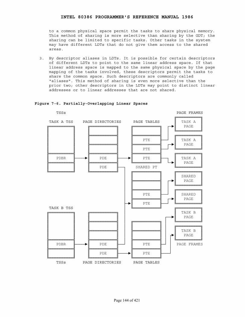
INTEL 80386 PROGRAMMER'S REFERENCE MANUAL 1986
Page 144 of 421
to a common physical space permit the tasks to share physical memory. This method of sharing is more selective than sharing by the GDT; the sharing can be limited to specific tasks. Other tasks in the system may have different LDTs that do not give them access to the shared areas.
3. By descriptor aliases in LDTs. It is possible for certain descriptors of different LDTs to point to the same linear address space. If that linear address space is mapped to the same physical space by the page mapping of the tasks involved, these descriptors permit the tasks to share the common space. Such descriptors are commonly called "aliases". This method of sharing is even more selective than the prior two; other descriptors in the LDTs may point to distinct linear addresses or to linear addresses that are not shared.
Figure 7-6. Partially-Overlapping Linear Spaces
TSSs PAGE FRAMES ╔══════════╗ TASK A TSS PAGE DIRECTORIES PAGE TABLES ║ TASK A ║ ╔══════════╗ ╔═══════════╗ ╔═══════════╗ ┌─►║ PAGE ║ ║ ║ ║ ║ ║ ║ │ ╚══════════╝ ║ ║ ╠═══════════╣ ╠═══════════╣ │ ╔══════════╗ ║ ║ ║ ║ ║ PTE ╟──┘ ║ TASK A ║ ║ ║ ╠═══════════╣ ╠═══════════╣ ┌─►║ PAGE ║ ║ ║ ║ ║ ║ PTE ╟──┘ ╚══════════╝ ╠══════════╣ ╠═══════════╣ ╠═══════════╣ ╔══════════╗ ║ PDBR ╟────►║ PDE ╟────►║ PTE ╟──┐ ║ TASK A ║ ╠══════════╣ ╠═══════════╣ ╚═══════════╝ └─►║ PAGE ║ ║ ║ ║ PDE ╟──┐ SHARED PT ╚══════════╝ ╚══════════╝ ╚═══════════╝ │ ╔═══════════╗ ╔══════════╗ │ ║ ║ ║ SHARED ║ │ ╠═══════════╣ ┌─►║ PAGE ║ │ ║ ║ │ ╚══════════╝ │ ╠═══════════╣ │ ╔══════════╗ │ ║ PTE ╟──┘ ║ SHARED ║ │ ╠═══════════╣ ┌─►║ PAGE ║ ├─►║ PTE ╟──┘ ╚══════════╝ TASK B TSS │ ╚═══════════╝ ╔══════════╗ ╔══════════╗ ╔═══════════╗ │ ║ TASK B ║ ║ ║ ║ ║ │ ┌──►║ PAGE ║ ║ ║ ╠═══════════╣ │ ╔═══════════╗ │ ╚══════════╝ ║ ║ ║ ║ │ ║ ║ │ ╔══════════╗ ║ ║ ╠═══════════╣ │ ╠═══════════╣ │ ║ TASK B ║ ║ ║ ║ ║ │ ║ ║ │ ┌►║ PAGE ║ ╠══════════╣ ╠═══════════╣ │ ╠═══════════╣ │ │ ╚══════════╝ ║ PDBR ╟────►║ PDE ╟──┘ ║ PTE ╟─┘ │ PAGE FRAMES ╠══════════╣ ╠═══════════╣ ╠═══════════╣ │ ║ ║ ║ PDE ╟────►║ PTE ╟───┘ ╚══════════╝ ╚═══════════╝ ╚═══════════╝ TSSs PAGE DIRECTORIES PAGE TABLES
INTEL 80386 PROGRAMMER'S REFERENCE MANUAL 1986
Page 145 of 421
Chapter 8 Input/Output
────────────────────────────────────────────────────────────────────────────
This chapter presents the I/O features of the 80386 from the followingperspectives:
● Methods of addressing I/O ports
● Instructions that cause I/O operations
● Protection as it applies to the use of I/O instructions and I/O port addresses.
8.1 I/O Addressing
The 80386 allows input/output to be performed in either of two ways:
● By means of a separate I/O address space (using specific I/O instructions)
● By means of memory-mapped I/O (using general-purpose operand manipulationinstructions).
8.1.1 I/O Address Space
The 80386 provides a separate I/O address space, distinct from physicalmemory, that can be used to address the input/output ports that are used forexternal 16 devices. The I/O address space consists of 216 (64K)individually addressable 8-bit ports; any two consecutive 8-bit ports can betreated as a 16-bit port; and four consecutive 8-bit ports can be treatedas a 32-bit port. Thus, the I/O address space can accommodate up to 64K8-bit ports, up to 32K 16-bit ports, or up to 16K 32-bit ports.
The program can specify the address of the port in two ways. Using animmediate byte constant, the program can specify:
● 256 8-bit ports numbered 0 through 255. ● 128 16-bit ports numbered 0, 2, 4, . . . , 252, 254. ● 64 32-bit ports numbered 0, 4, 8, . . . , 248, 252.
Using a value in DX, the program can specify:
● 8-bit ports numbered 0 through 65535 ● 16-bit ports numbered 0, 2, 4, . . . , 65532, 65534 ● 32-bit ports numbered 0, 4, 8, . . . , 65528, 65532
The 80386 can transfer 32, 16, or 8 bits at a time to a device located inthe I/O space. Like doublewords in memory, 32-bit ports should be aligned ataddresses evenly divisible by four so that the 32 bits can be transferred in
INTEL 80386 PROGRAMMER'S REFERENCE MANUAL 1986
Page 146 of 421
a single bus access. Like words in memory, 16-bit ports should be aligned ateven-numbered addresses so that the 16 bits can be transferred in a singlebus access. An 8-bit port may be located at either an even or odd address.
The instructions IN and OUT move data between a register and a port in theI/O address space. The instructions INS and OUTS move strings of databetween the memory address space and ports in the I/O address space.
8.1.2 Memory-Mapped I/O
I/O devices also may be placed in the 80386 memory address space. As longas the devices respond like memory components, they are indistinguishable tothe processor.
Memory-mapped I/O provides additional programming flexibility. Anyinstruction that references memory may be used to access an I/O port locatedin the memory space. For example, the MOV instruction can transfer databetween any register and a port; and the AND, OR, and TEST instructions maybe used to manipulate bits in the internal registers of a device (see Figure8-1). Memory-mapped I/O performed via the full instruction set maintainsthe full complement of addressing modes for selecting the desired I/Odevice (e.g., direct address, indirect address, base register, indexregister, scaling).
Memory-mapped I/O, like any other memory reference, is subject to accessprotection and control when executing in protected mode. Refer to Chapter 6for a discussion of memory protection.
8.2 I/O Instructions
The I/O instructions of the 80386 provide access to the processor's I/Oports for the transfer of data to and from peripheral devices. Theseinstructions have as one operand the address of a port in the I/O addressspace. There are two classes of I/O instruction:
1. Those that transfer a single item (byte, word, or doubleword) located in a register.
2. Those that transfer strings of items (strings of bytes, words, or doublewords) located in memory. These are known as "string I/O instructions" or "block I/O instructions".
8.2.1 Register I/O Instructions
The I/O instructions IN and OUT are provided to move data between I/O portsand the EAX (32-bit I/O), the AX (16-bit I/O), or AL (8-bit I/O) generalregisters. IN and OUT instructions address I/O ports either directly, withthe address of one of up to 256 port addresses coded in the instruction, orindirectly via the DX register to one of up to 64K port addresses.
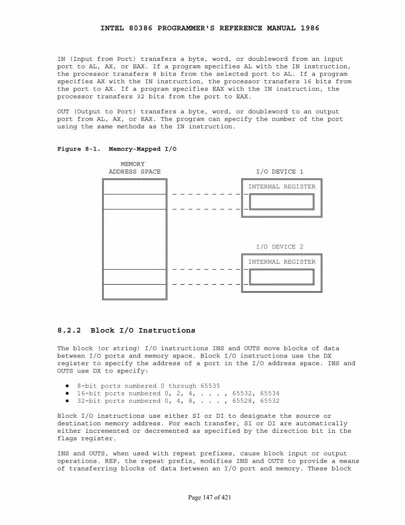
INTEL 80386 PROGRAMMER'S REFERENCE MANUAL 1986
Page 147 of 421
IN (Input from Port) transfers a byte, word, or doubleword from an inputport to AL, AX, or EAX. If a program specifies AL with the IN instruction,the processor transfers 8 bits from the selected port to AL. If a programspecifies AX with the IN instruction, the processor transfers 16 bits fromthe port to AX. If a program specifies EAX with the IN instruction, theprocessor transfers 32 bits from the port to EAX.
OUT (Output to Port) transfers a byte, word, or doubleword to an outputport from AL, AX, or EAX. The program can specify the number of the portusing the same methods as the IN instruction.
Figure 8-1. Memory-Mapped I/O
MEMORY ADDRESS SPACE I/O DEVICE 1 ╔═══════════════╗ ╔═══════════════════╗ ║ ║ ║ INTERNAL REGISTER ║ ╟───────────────╢ ─ ─ ─ ─ ─ ─ ─ ─ ─║─╔═══════════════╗ ║ ║ ║ ║ ║ ║ ║ ╟───────────────╢ ─ ─ ─ ─ ─ ─ ─ ─ ─║─╚═══════════════╝ ║ ║ ║ ╚═══════════════════╝ ║ ║ ║ ║ ║ ║ ║ ║ I/O DEVICE 2 ║ ║ ╔═══════════════════╗ ║ ║ ║ INTERNAL REGISTER ║ ╟───────────────╢ ─ ─ ─ ─ ─ ─ ─ ─ ─║─╔═══════════════╗ ║ ║ ║ ║ ║ ║ ║ ╟───────────────╢ ─ ─ ─ ─ ─ ─ ─ ─ ─║─╚═══════════════╝ ║ ║ ║ ╚═══════════════════╝ ╚═══════════════╝
8.2.2 Block I/O Instructions
The block (or string) I/O instructions INS and OUTS move blocks of databetween I/O ports and memory space. Block I/O instructions use the DXregister to specify the address of a port in the I/O address space. INS andOUTS use DX to specify:
● 8-bit ports numbered 0 through 65535 ● 16-bit ports numbered 0, 2, 4, . . . , 65532, 65534 ● 32-bit ports numbered 0, 4, 8, . . . , 65528, 65532
Block I/O instructions use either SI or DI to designate the source ordestination memory address. For each transfer, SI or DI are automaticallyeither incremented or decremented as specified by the direction bit in theflags register.
INS and OUTS, when used with repeat prefixes, cause block input or outputoperations. REP, the repeat prefix, modifies INS and OUTS to provide a meansof transferring blocks of data between an I/O port and memory. These block
INTEL 80386 PROGRAMMER'S REFERENCE MANUAL 1986
Page 148 of 421
I/O instructions are string primitives (refer also to Chapter 3 for more onstring primitives). They simplify programming and increase the speed of datatransfer by eliminating the need to use a separate LOOP instruction or anintermediate register to hold the data.
The string I/O primitives can operate on byte strings, word strings, ordoubleword strings. After each transfer, the memory address in ESI or EDI isupdated by 1 for byte operands, by 2 for word operands, or by 4 fordoubleword operands. The value in the direction flag (DF) determines whetherthe processor automatically increments ESI or EDI (DF=0) or whether itautomatically decrements these registers (DF=1).
INS (Input String from Port) transfers a byte or a word string element froman input port to memory. The mnemonics INSB, INSW, and INSD are variantsthat explicitly specify the size of the operand. If a program specifiesINSB, the processor transfers 8 bits from the selected port to the memorylocation indicated by ES:EDI. If a program specifies INSW, the processortransfers 16 bits from the port to the memory location indicated by ES:EDI.If a program specifies INSD, the processor transfers 32 bits from the portto the memory location indicated by ES:EDI. The destination segment registerchoice (ES) cannot be changed for the INS instruction. Combined with the REPprefix, INS moves a block of information from an input port to a series ofconsecutive memory locations.
OUTS (Output String to Port) transfers a byte, word, or doubleword stringelement to an output port from memory. The mnemonics OUTSB, OUTSW, and OUTSDare variants that explicitly specify the size of the operand. If a programspecifies OUTSB, the processor transfers 8 bits from the memory locationindicated by ES:EDI to the the selected port. If a program specifies OUTSW,the processor transfers 16 bits from the memory location indicated by ES:EDIto the the selected port. If a program specifies OUTSD, the processortransfers 32 bits from the memory location indicated by ES:EDI to the theselected port. Combined with the REP prefix, OUTS moves a block ofinformation from a series of consecutive memory locations indicated byDS:ESI to an output port.
8.3 Protection and I/O
Two mechanisms provide protection for I/O functions:
1. The IOPL field in the EFLAGS register defines the right to use I/O-related instructions.
2. The I/O permission bit map of a 80386 TSS segment defines the right to use ports in the I/O address space.
These mechanisms operate only in protected mode, including virtual 8086mode; they do not operate in real mode. In real mode, there is no protectionof the I/O space; any procedure can execute I/O instructions, and any I/Oport can be addressed by the I/O instructions.
INTEL 80386 PROGRAMMER'S REFERENCE MANUAL 1986
Page 149 of 421
8.3.1 I/O Privilege Level
Instructions that deal with I/O need to be restricted but also need to beexecuted by procedures executing at privilege levels other than zero. Forthis reason, the processor uses two bits of the flags register to store theI/O privilege level (IOPL). The IOPL defines the privilege levelneeded to execute I/O-related instructions.
The following instructions can be executed only if CPL ≤ IOPL:
IN ── InputINS ── Input StringOUT ── OutputOUTS ── Output StringCLI ── Clear Interrupt-Enable FlagSTI ── Set Interrupt-Enable
These instructions are called "sensitive" instructions, because they aresensitive to IOPL.
To use sensitive instructions, a procedure must execute at a privilegelevel at least as privileged as that specified by the IOPL (CPL ≤ IOPL). Anyattempt by a less privileged procedure to use a sensitive instructionresults in a general protection exception.
Because each task has its own unique copy of the flags register, each taskcan have a different IOPL. A task whose primary function is to perform I/O(a device driver) can benefit from having an IOPL of three, therebypermitting all procedures of the task to performI/O. Other tasks typicallyhave IOPL set to zero or one, reserving the right to perform I/Oinstructions for the most privileged procedures.
A task can change IOPL only with the POPF instruction; however, suchchanges are privileged. No procedure may alter IOPL (the I/O privilege levelin the flag register) unless the procedure is executing at privilege level0. An attempt by a less privileged procedure to alter IOPL does not resultin an exception; IOPL simply remains unaltered.
The POPF instruction may be used in addition to CLI and STI to alter theinterrupt-enable flag (IF); however, changes to IF by POPF areIOPL-sensitive. A procedure may alter IF with a POPF instruction only whenexecuting at a level that is at least as privileged as IOPL. An attempt by aless privileged procedure to alter IF in this manner does not result in anexception; IF simply remains unaltered.
8.3.2 I/O Permission Bit Map
The I/O instructions that directly refer to addresses in the processor'sI/O space are IN, INS, OUT, OUTS. The 80386 has the ability to selectivelytrap references to specific I/O addresses. The structure that enablesselective trapping is the I/O Permission Bit Map in the TSS segment (seeFigure 8-2). The I/O permission map is a bit vector. The size of the mapand its location in the TSS segment are variable. The processor locates the
INTEL 80386 PROGRAMMER'S REFERENCE MANUAL 1986
Page 150 of 421
I/O permission map by means of the I/O map base field in the fixed portionof the TSS. The I/O map base field is 16 bits wide and contains the offsetof the beginning of the I/O permission map. The upper limit of the I/Opermission map is the same as the limit of the TSS segment.
In protected mode, when it encounters an I/O instruction (IN, INS, OUT, orOUTS), the processor first checks whether CPL ≤ IOPL. If this condition istrue, the I/O operation may proceed. If not true, the processor checks theI/O permission map. (In virtual 8086 mode, the processor consults the mapwithout regard for IOPL. Refer to Chapter 15.)
Each bit in the map corresponds to an I/O port byte address; for example,the bit for port 41 is found at I/O map base + 5, bit offset 1. Theprocessor tests all the bits that correspond to the I/O addresses spanned byan I/O operation; for example, a doubleword operation tests four bitscorresponding to four adjacent byte addresses. If any tested bit is set,the processor signals a general protection exception. If all the tested bitsare zero, the I/O operation may proceed.
It is not necessary for the I/O permission map to represent all the I/Oaddresses. I/O addresses not spanned by the map are treated as if they hadone bits in the map. For example, if TSS limit is equal to I/O map base +31, the first 256 I/O ports are mapped; I/O operations on any port greaterthan 255 cause an exception.
If I/O map base is greater than or equal to TSS limit, the TSS segment hasno I/O permission map, and all I/O instructions in the 80386 program causeexceptions when CPL > IOPL.
Because the I/O permission map is in the TSS segment, different tasks canhave different maps. Thus, the operating system can allocate ports to a taskby changing the I/O permission map in the task's TSS.
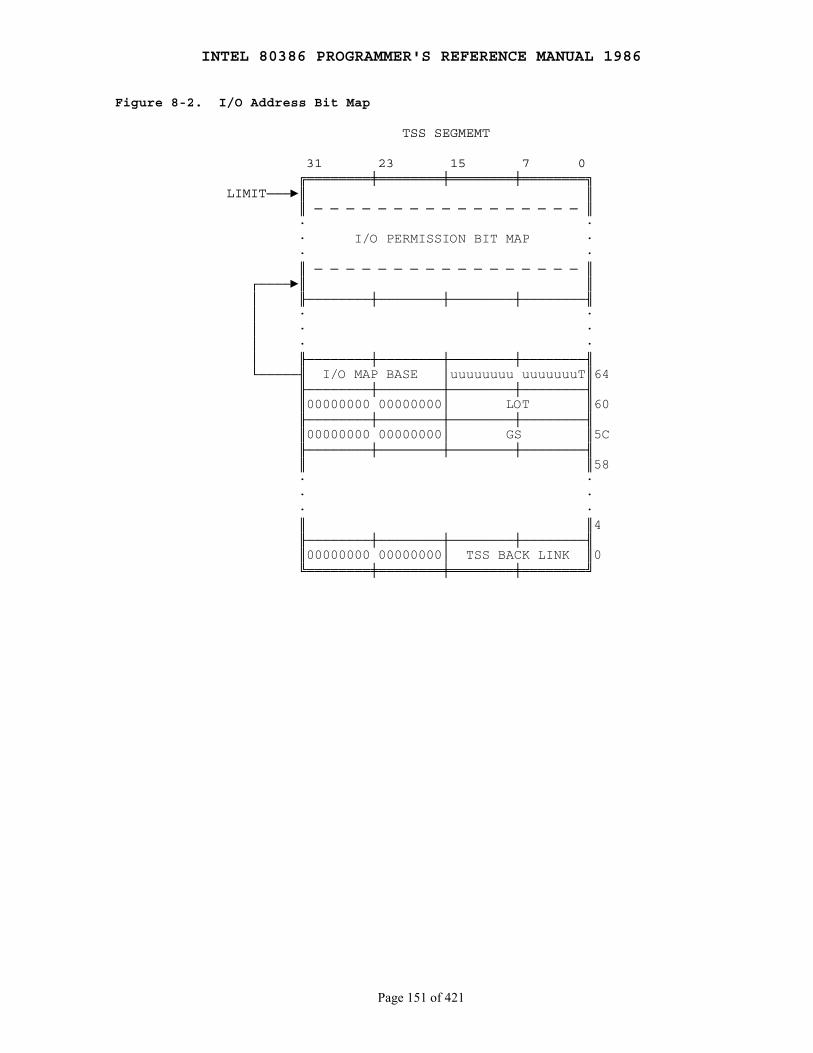
INTEL 80386 PROGRAMMER'S REFERENCE MANUAL 1986
Page 151 of 421
Figure 8-2. I/O Address Bit Map
TSS SEGMEMT
31 23 15 7 0 ╔════════╪════════╪════════╪════════╗ LIMIT───►║ ║ ║ ─ ─ ─ ─ ─ ─ ─ ─ ─ ─ ─ ─ ─ ─ ─ ─ ─ ║ · · · I/O PERMISSION BIT MAP · · · ║ ─ ─ ─ ─ ─ ─ ─ ─ ─ ─ ─ ─ ─ ─ ─ ─ ─ ║ ┌────►║ ║ │ ╟────────┼────────┼────────┼────────╢ │ · · │ · · │ · · │ ╟────────┼────────┼────────┼────────╢ └─────╢ I/O MAP BASE │uuuuuuuu uuuuuuuT║64 ╟────────┼────────┼────────┼────────╢ ║00000000 00000000│ LOT ║60 ╟────────┼────────┼────────┼────────╢ ║00000000 00000000│ GS ║5C ╟────────┼────────┼────────┼────────╢ ║ ║58 · · · · · · ║ ║4 ╟────────┼────────┼────────┼────────╢ ║00000000 00000000│ TSS BACK LINK ║0 ╚════════╪════════╪════════╪════════╝
INTEL 80386 PROGRAMMER'S REFERENCE MANUAL 1986
Page 152 of 421
Chapter 9 Exceptions and Interrupts
────────────────────────────────────────────────────────────────────────────
Interrupts and exceptions are special kinds of control transfer; they worksomewhat like unprogrammed CALLs. They alter the normal program flow tohandle external events or to report errors or exceptional conditions. Thedifference between interrupts and exceptions is that interrupts are used tohandle asynchronous events external to the processor, but exceptions handleconditions detected by the processor itself in the course of executinginstructions.
There are two sources for external interrupts and two sources forexceptions:
1. Interrupts
● Maskable interrupts, which are signalled via the INTR pin.
● Nonmaskable interrupts, which are signalled via the NMI (Non-Maskable Interrupt) pin.
2. Exceptions
● Processor detected. These are further classified as faults, traps, and aborts.
● Programmed. The instructions INTO, INT 3, INT n, and BOUND can trigger exceptions. These instructions are often called "software interrupts", but the processor handles them as exceptions.
This chapter explains the features that the 80386 offers for controllingand responding to interrupts when it is executing in protected mode.
9.1 Identifying Interrupts
The processor associates an identifying number with each different type ofinterrupt or exception.
The NMI and the exceptions recognized by the processor are assignedpredetermined identifiers in the range 0 through 31. Not all of thesenumbers are currently used by the 80386; unassigned identifiers in thisrange are reserved by Intel for possible future expansion.
The identifiers of the maskable interrupts are determined by externalinterrupt controllers (such as Intel's 8259A Programmable InterruptController) and communicated to the processor during the processor'sinterrupt-acknowledge sequence. The numbers assigned by an 8259A PIC can bespecified by software. Any numbers in the range 32 through 255 can be used.Table 9-1 shows the assignment of interrupt and exception identifiers.

INTEL 80386 PROGRAMMER'S REFERENCE MANUAL 1986
Page 153 of 421
Exceptions are classified as faults, traps, or aborts depending on the waythey are reported and whether restart of the instruction that caused theexception is supported.
Faults Faults are exceptions that are reported "before" the instruction causingthe exception. Faults are either detected before the instruction begins to execute, or during execution of the instruction. If detected during the instruction, the fault is reported with the machine restored to a state that permits the instruction to be restarted.
Traps A trap is an exception that is reported at the instruction boundary immediately after the instruction in which the exception was detected.
Aborts An abort is an exception that permits neither precise location of the instruction causing the exception nor restart of the program that caused the exception. Aborts are used to report severe errors, such as hardware errors and inconsistent or illegal values in system tables.
Table 9-1. Interrupt and Exception ID Assignments
Identifier Description
0 Divide error1 Debug exceptions2 Nonmaskable interrupt3 Breakpoint (one-byte INT 3 instruction)4 Overflow (INTO instruction)5 Bounds check (BOUND instruction)6 Invalid opcode7 Coprocessor not available8 Double fault9 (reserved)10 Invalid TSS11 Segment not present12 Stack exception13 General protection14 Page fault15 (reserved)16 Coprecessor error17-31 (reserved)32-255 Available for external interrupts via INTR pin
9.2 Enabling and Disabling Interrupts
The processor services interrupts and exceptions only between the end ofone instruction and the beginning of the next. When the repeat prefix isused to repeat a string instruction, interrupts and exceptions may occurbetween repetitions. Thus, operations on long strings do not delay interruptresponse.
INTEL 80386 PROGRAMMER'S REFERENCE MANUAL 1986
Page 154 of 421
Certain conditions and flag settings cause the processor to inhibit certaininterrupts and exceptions at instruction boundaries.
9.2.1 NMI Masks Further NMIs
While an NMI handler is executing, the processor ignores further interruptsignals at the NMI pin until the next IRET instruction is executed.
9.2.2 IF Masks INTR
The IF (interrupt-enable flag) controls the acceptance of externalinterrupts signalled via the INTR pin. When IF=0, INTR interrupts areinhibited; when IF=1, INTR interrupts are enabled. As with the other flagbits, the processor clears IF in response to a RESET signal. Theinstructions CLI and STI alter the setting of IF.
CLI (Clear Interrupt-Enable Flag) and STI (Set Interrupt-Enable Flag)explicitly alter IF (bit 9 in the flag register). These instructions may beexecuted only if CPL ≤ IOPL. A protection exception occurs if they areexecuted when CPL > IOPL.
The IF is also affected implicitly by the following operations:
● The instruction PUSHF stores all flags, including IF, in the stack where they can be examined.
● Task switches and the instructions POPF and IRET load the flags register; therefore, they can be used to modify IF.
● Interrupts through interrupt gates automatically reset IF, disabling interrupts. (Interrupt gates are explained later in this chapter.)
9.2.3 RF Masks Debug Faults
The RF bit in EFLAGS controls the recognition of debug faults. This permitsdebug faults to be raised for a given instruction at most once, no matterhow many times the instruction is restarted. (Refer to Chapter 12 for moreinformation on debugging.)
9.2.4 MOV or POP to SS Masks Some Interrupts and Exceptions
Software that needs to change stack segments often uses a pair ofinstructions; for example:
MOV SS, AX MOV ESP, StackTop
INTEL 80386 PROGRAMMER'S REFERENCE MANUAL 1986
Page 155 of 421
If an interrupt or exception is processed after SS has been changed butbefore ESP has received the corresponding change, the two parts of the stackpointer SS:ESP are inconsistent for the duration of the interrupt handler orexception handler.
To prevent this situation, the 80386, after both a MOV to SS and a POP toSS instruction, inhibits NMI, INTR, debug exceptions, and single-step trapsat the instruction boundary following the instruction that changes SS. Someexceptions may still occur; namely, page fault and general protection fault.Always use the 80386 LSS instruction, and the problem will not occur.
9.3 Priority Among Simultaneous Interrupts and Exceptions
If more than one interrupt or exception is pending at an instructionboundary, the processor services one of them at a time. The priority amongclasses of interrupt and exception sources is shown in Table 9-2. Theprocessor first services a pending interrupt or exception from the classthat has the highest priority, transferring control to the firstinstruction of the interrupt handler. Lower priority exceptions arediscarded; lower priority interrupts are held pending. Discarded exceptionswill be rediscovered when the interrupt handler returns control to the pointof interruption.
9.4 Interrupt Descriptor Table
The interrupt descriptor table (IDT) associates each interrupt or exceptionidentifier with a descriptor for the instructions that service theassociated event. Like the GDT and LDTs, the IDT is an array of 8-bytedescriptors. Unlike the GDT and LDTs, the first entry of the IDT may containa descriptor. To form an index into the IDT, the processor multiplies theinterrupt or exception identifier by eight. Because there are only 256identifiers, the IDT need not contain more than 256 descriptors. It cancontain fewer than 256 entries; entries are required only for interruptidentifiers that are actually used.
The IDT may reside anywhere in physical memory. As Figure 9-1 shows, theprocessor locates the IDT by means of the IDT register (IDTR). Theinstructions LIDT and SIDT operate on the IDTR. Both instructions have oneexplicit operand: the address in memory of a 6-byte area. Figure 9-2 showsthe format of this area.
LIDT (Load IDT register) loads the IDT register with the linear baseaddress and limit values contained in the memory operand. This instructioncan be executed only when the CPL is zero. It is normally used by theinitialization logic of an operating system when creating an IDT. Anoperating system may also use it to change from one IDT to another.
SIDT (Store IDT register) copies the base and limit value stored in IDTRto a memory location. This instruction can be executed at any privilegelevel.
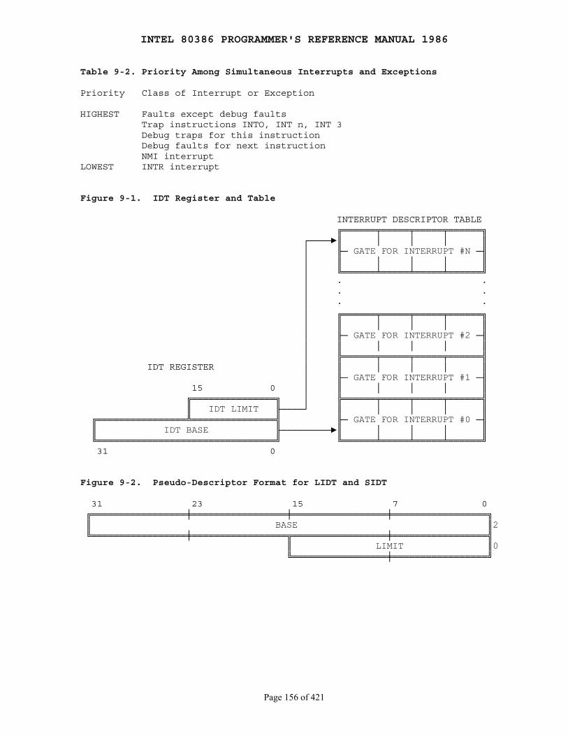
INTEL 80386 PROGRAMMER'S REFERENCE MANUAL 1986
Page 156 of 421
Table 9-2. Priority Among Simultaneous Interrupts and Exceptions
Priority Class of Interrupt or Exception
HIGHEST Faults except debug faults Trap instructions INTO, INT n, INT 3 Debug traps for this instruction Debug faults for next instruction NMI interruptLOWEST INTR interrupt
Figure 9-1. IDT Register and Table
INTERRUPT DESCRIPTOR TABLE ╔══════╤═════╤═════╤══════╗ ┌────►║ │ │ │ ║ │ ╟─ GATE FOR INTERRUPT #N ─╢ │ ║ │ │ │ ║ │ ╚══════╧═════╧═════╧══════╝ │ · · │ · · │ · · │ ╔══════╤═════╤═════╤══════╗ │ ║ │ │ │ ║ │ ╟─ GATE FOR INTERRUPT #2 ─╢ │ ║ │ │ │ ║ │ ╠══════╤═════╤═════╤══════╣ IDT REGISTER │ ║ │ │ │ ║ │ ╟─ GATE FOR INTERRUPT #1 ─╢ 15 0 │ ║ │ │ │ ║ ╔═══════════════╗ │ ╠══════╤═════╤═════╤══════╣ ║ IDT LIMIT ╟────┘ ║ │ │ │ ║ ╔════════════════╩═══════════════╣ ╟─ GATE FOR INTERRUPT #0 ─╢ ║ IDT BASE ╟─────────►║ │ │ │ ║ ╚════════════════════════════════╝ ╚══════╧═════╧═════╧══════╝ 31 0
Figure 9-2. Pseudo-Descriptor Format for LIDT and SIDT
31 23 15 7 0 ╔═════════════════╪═════════════════╪═════════════════╪═════════════════╗ ║ BASE ║2 ╚═════════════════╪═════════════════╦═════════════════╪═════════════════╣ ║ LIMIT ║0 ╚═════════════════╪═════════════════╝
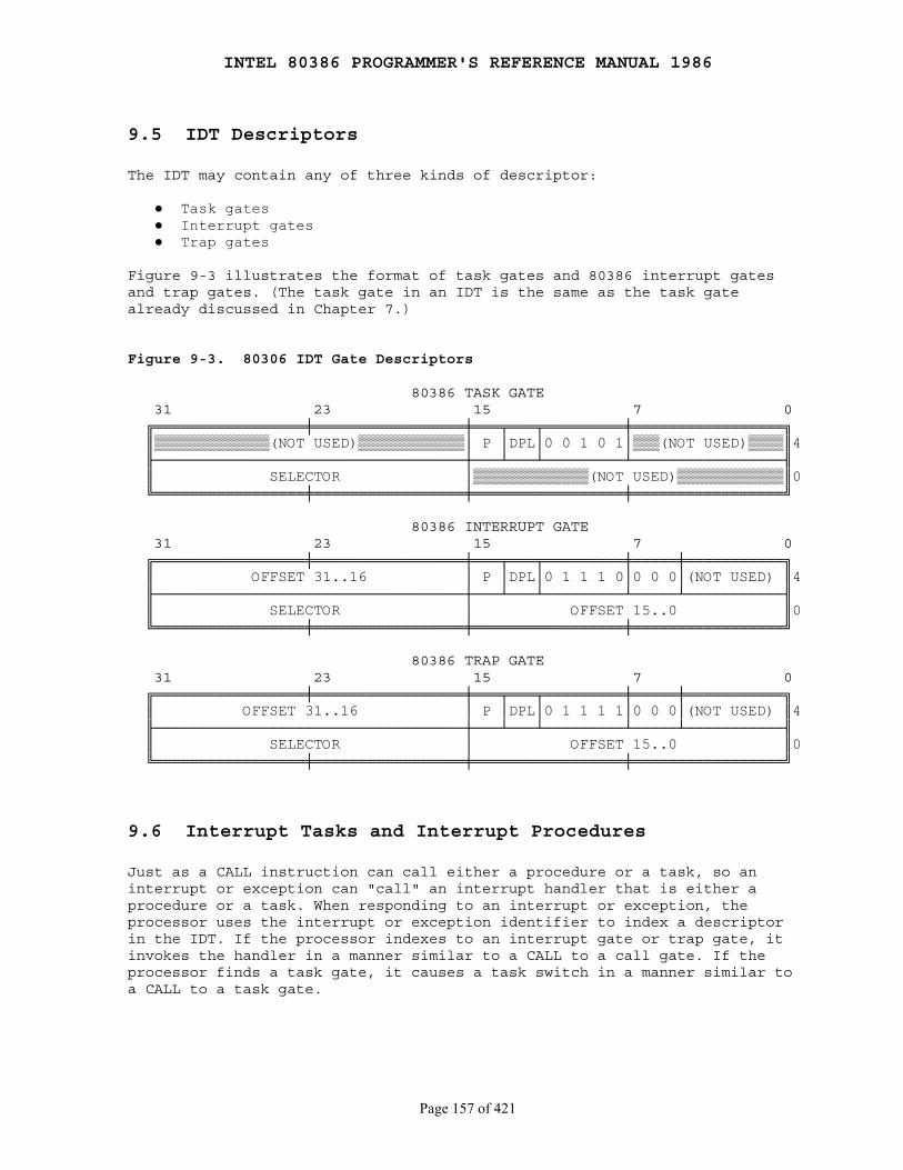
INTEL 80386 PROGRAMMER'S REFERENCE MANUAL 1986
Page 157 of 421
9.5 IDT Descriptors
The IDT may contain any of three kinds of descriptor:
● Task gates ● Interrupt gates ● Trap gates
Figure 9-3 illustrates the format of task gates and 80386 interrupt gatesand trap gates. (The task gate in an IDT is the same as the task gatealready discussed in Chapter 7.)
Figure 9-3. 80306 IDT Gate Descriptors
80386 TASK GATE 31 23 15 7 0 ╔═════════════════╪═════════════════╪═══╤═══╤═════════╪═════════════════╗ ║▒▒▒▒▒▒▒▒▒▒▒▒▒(NOT USED)▒▒▒▒▒▒▒▒▒▒▒▒│ P │DPL│0 0 1 0 1│▒▒▒(NOT USED)▒▒▒▒║4 ╟───────────────────────────────────┼───┴───┴─────────┴─────────────────╢ ║ SELECTOR │▒▒▒▒▒▒▒▒▒▒▒▒▒(NOT USED)▒▒▒▒▒▒▒▒▒▒▒▒║0 ╚═════════════════╪═════════════════╪═════════════════╪═════════════════╝
80386 INTERRUPT GATE 31 23 15 7 0 ╔═════════════════╪═════════════════╪═══╤═══╤═════════╪═════╪═══════════╗ ║ OFFSET 31..16 │ P │DPL│0 1 1 1 0│0 0 0│(NOT USED) ║4 ╟───────────────────────────────────┼───┴───┴─────────┴─────┴───────────╢ ║ SELECTOR │ OFFSET 15..0 ║0 ╚═════════════════╪═════════════════╪═════════════════╪═════════════════╝
80386 TRAP GATE 31 23 15 7 0 ╔═════════════════╪═════════════════╪═══╤═══╤═════════╪═════╪═══════════╗ ║ OFFSET 31..16 │ P │DPL│0 1 1 1 1│0 0 0│(NOT USED) ║4 ╟───────────────────────────────────┼───┴───┴─────────┴─────┴───────────╢ ║ SELECTOR │ OFFSET 15..0 ║0 ╚═════════════════╪═════════════════╪═════════════════╪═════════════════╝
9.6 Interrupt Tasks and Interrupt Procedures
Just as a CALL instruction can call either a procedure or a task, so aninterrupt or exception can "call" an interrupt handler that is either aprocedure or a task. When responding to an interrupt or exception, theprocessor uses the interrupt or exception identifier to index a descriptorin the IDT. If the processor indexes to an interrupt gate or trap gate, itinvokes the handler in a manner similar to a CALL to a call gate. If theprocessor finds a task gate, it causes a task switch in a manner similar toa CALL to a task gate.

INTEL 80386 PROGRAMMER'S REFERENCE MANUAL 1986
Page 158 of 421
9.6.1 Interrupt Procedures
An interrupt gate or trap gate points indirectly to a procedure which willexecute in the context of the currently executing task as illustrated byFigure 9-4. The selector of the gate points to an executable-segmentdescriptor in either the GDT or the current LDT. The offset field of thegate points to the beginning of the interrupt or exception handlingprocedure.
The 80386 invokes an interrupt or exception handling procedure in much thesame manner as it CALLs a procedure; the differences are explained in thefollowing sections.
Figure 9-4. Interrupt Vectoring for Procedures
IDT EXECUTABLE SEGMENT ╔═══════════════╗ ╔═══════════════╗ ║ ║ OFFSET║ ║ ╠═══════════════╣ ┌─────────────────────────►║ ENTRY POINT ║ ║ ║ │ LDT OR GDT ║ ║ ╠═══════════════╣ │ ╔═══════════════╗ ║ ║ ║ ║ │ ║ ║ ║ ║INTERRUPT ╠═══════════════╣ │ ╠═══════════════╣ ║ ║ ID─────►║ TRAP GATE OR ╟──┘ ║ ║ ║ ║ ║INTERRUPT GATE ╟──┐ ╠═══════════════╣ ║ ║ ╠═══════════════╣ │ ║ ║ ║ ║ ║ ║ │ ╠═══════════════╣ ║ ║ ╠═══════════════╣ └──►║ SEGMENT ╟─┐ ║ ║ ║ ║ ║ DESCRIPTOR ║ │ ║ ║ ╠═══════════════╣ ╠═══════════════╣ │ ║ ║ ║ ║ ║ ║ │ ║ ║ ╠═══════════════╣ ╠═══════════════╣ │ ║ ║ ║ ║ ║ ║ │BASE║ ║ ╚═══════════════╝ ╠═══════════════╣ └───►╚═══════════════╝ ║ ║ ║ ║ ║ ║ ╚═══════════════╝
9.6.1.1 Stack of Interrupt Procedure
Just as with a control transfer due to a CALL instruction, a controltransfer to an interrupt or exception handling procedure uses the stack tostore the information needed for returning to the original procedure. AsFigure 9-5 shows, an interrupt pushes the EFLAGS register onto the stackbefore the pointer to the interrupted instruction.
Certain types of exceptions also cause an error code to be pushed on thestack. An exception handler can use the error code to help diagnose theexception.

INTEL 80386 PROGRAMMER'S REFERENCE MANUAL 1986
Page 159 of 421
9.6.1.2 Returning from an Interrupt Procedure
An interrupt procedure also differs from a normal procedure in the methodof leaving the procedure. The IRET instruction is used to exit from aninterrupt procedure. IRET is similar to RET except that IRET increments EIPby an extra four bytes (because of the flags on the stack) and moves thesaved flags into the EFLAGS register. The IOPL field of EFLAGS is changedonly if the CPL is zero. The IF flag is changed only if CPL ≤ IOPL.
Figure 9-5. Stack Layout after Exception of Interrupt
WITHOUT PRIVILEGE TRANSITION
D O 31 0 31 0 I F ╠═══════╦═══════╣ ╠═══════╦═══════╣ R ║▒▒▒▒▒▒▒║▒▒▒▒▒▒▒║ OLD ║▒▒▒▒▒▒▒║▒▒▒▒▒▒▒║ OLD E E ╠═══════╬═══════╣ SS:ESP ╠═══════╬═══════╣ SS:ESP C X ║▒▒▒▒▒▒▒║▒▒▒▒▒▒▒║ │ ║▒▒▒▒▒▒▒║▒▒▒▒▒▒▒║ │ T P ╠═══════╩═══════╣◄────┘ ╠═══════╩═══════╣◄────┘ I A ║ OLD EFLAGS ║ ║ OLD EFLAGS ║ O N ╠═══════╦═══════╣ ╠═══════╦═══════╣ N S ║▒▒▒▒▒▒▒║OLD CS ║ NEW ║▒▒▒▒▒▒▒║OLD CS ║ I ╠═══════╩═══════╣ SS:ESP ╠═══════╩═══════╣ │ O ║ OLD EIP ║ │ ║ OLD EIP ║ NEW │ N ╠═══════════════╣◄────┘ ╠═══════════════╣ SS:ESP │ ║ ║ ║ ERROR CODE ║ │ ▼ · · ╠═══════════════╣◄────┘ · · ║ ║ · · WITHOUT ERROR CODE WITH ERROR CODE
WITH PRIVILEGE TRANSITION
D O 31 0 31 0 I F ╔═══════╦═══════╗◄────┐ ╔═══════╦═══════╗◄────┐ R ║▒▒▒▒▒▒▒║OLD SS ║ │ ║▒▒▒▒▒▒▒║OLD SS ║ │ E E ╠═══════╩═══════╣ SS:ESP ╠═══════╩═══════╣ SS:ESP C X ║ OLD ESP ║ FROM TSS ║ OLD ESP ║ FROM TSS T P ╠═══════════════╣ ╠═══════════════╣ I A ║ OLD EFLAGS ║ ║ OLD EFLAGS ║ O N ╠═══════╦═══════╣ ╠═══════╦═══════╣ N S ║▒▒▒▒▒▒▒║OLD CS ║ NEW ║▒▒▒▒▒▒▒║OLD CS ║ I ╠═══════╩═══════╣ SS:EIP ╠═══════╩═══════╣ │ O ║ OLD EIP ║ │ ║ OLD EIP ║ NEW │ N ╠═══════════════╣◄────┘ ╠═══════════════╣ SS:ESP │ ║ ║ ║ ERROR CODE ║ │ ▼ · · ╠═══════════════╣◄────┘ · · ║ ║ · · WITHOUT ERROR CODE WITH ERROR CODE
INTEL 80386 PROGRAMMER'S REFERENCE MANUAL 1986
Page 160 of 421
9.6.1.3 Flags Usage by Interrupt Procedure
Interrupts that vector through either interrupt gates or trap gates causeTF (the trap flag) to be reset after the current value of TF is saved on thestack as part of EFLAGS. By this action the processor prevents debuggingactivity that uses single-stepping from affecting interrupt response. Asubsequent IRET instruction restores TF to the value in the EFLAGS image onthe stack.
The difference between an interrupt gate and a trap gate is in the effecton IF (the interrupt-enable flag). An interrupt that vectors through aninterrupt gate resets IF, thereby preventing other interrupts frominterfering with the current interrupt handler. A subsequent IRETinstruction restores IF to the value in the EFLAGS image on the stack. Aninterrupt through a trap gate does not change IF.
9.6.1.4 Protection in Interrupt Procedures
The privilege rule that governs interrupt procedures is similar to that forprocedure calls: the CPU does not permit an interrupt to transfer control toa procedure in a segment of lesser privilege (numerically greater privilegelevel) than the current privilege level. An attempt to violate this ruleresults in a general protection exception.
Because occurrence of interrupts is not generally predictable, thisprivilege rule effectively imposes restrictions on the privilege levels atwhich interrupt and exception handling procedures can execute. Either of thefollowing strategies can be employed to ensure that the privilege rule isnever violated.
● Place the handler in a conforming segment. This strategy suits the handlers for certain exceptions (divide error, for example). Such a handler must use only the data available to it from the stack. If it needed data from a data segment, the data segment would have to have privilege level three, thereby making it unprotected.
● Place the handler procedure in a privilege level zero segment.
9.6.2 Interrupt Tasks
A task gate in the IDT points indirectly to a task, as Figure 9-6illustrates. The selector of the gate points to a TSS descriptor in the GDT.
When an interrupt or exception vectors to a task gate in the IDT, a taskswitch results. Handling an interrupt with a separate task offers twoadvantages:
● The entire context is saved automatically.

INTEL 80386 PROGRAMMER'S REFERENCE MANUAL 1986
Page 161 of 421
● The interrupt handler can be isolated from other tasks by giving it a separate address space, either via its LDT or via its page directory.
The actions that the processor takes to perform a task switch are discussedin Chapter 7. The interrupt task returns to the interrupted task byexecuting an IRET instruction.
If the task switch is caused by an exception that has an error code, theprocessor automatically pushes the error code onto the stack thatcorresponds to the privilege level of the first instruction to be executedin the interrupt task.
When interrupt tasks are used in an operating system for the 80386, thereare actually two schedulers: the software scheduler (part of the operatingsystem) and the hardware scheduler (part of the processor's interruptmechanism). The design of the software scheduler should account for the factthat the hardware scheduler may dispatch an interrupt task wheneverinterrupts are enabled.
Figure 9-6. Interrupt Vectoring for Tasks
IDT GDT ╔════════════════╗ ╔════════════════╗ ║ ║ ║ ║ TSS ╟────────────────╢ ╟────────────────╢ ╔════════════════╗ ║ ║ ║ ║ ║ ║ ╟────────────────╢ ╟────────────────╢ ║ ║ ║ ║ ║ ║ ║ ║ ╟────────────────╢ ╟────────────────╢ ║ ║ ┌──►║ TASK GATE ╟───┐ ║ ║ ║ ║ │ ╟────────────────╢ │ ╟────────────────╢ ║ ║ │ ║ ║ └───►║ TSS DESCRIPTOR ╟───┐ ║ ║ │ ╟────────────────╢ ╟────────────────╢ │ ║ ║ │ ║ ║ ║ ║ │ ║ ║ │ ╟────────────────╢ ╟────────────────╢ └──►╚════════════════╝ │ ║ ║ ║ ║ │ ╟────────────────╢ ╟────────────────╢ │ ║ ║ ║ ║ │ ╚════════════════╝ ╚════════════════╝ │ └─INTERRUPT ID
9.7 Error Code
With exceptions that relate to a specific segment, the processor pushes anerror code onto the stack of the exception handler (whether procedure ortask). The error code has the format shown in Figure 9-7. The format of theerror code resembles that of a selector; however, instead of an RPL field,the error code contains two one-bit items:
1. The processor sets the EXT bit if an event external to the program caused the exception.
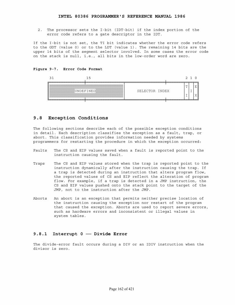
INTEL 80386 PROGRAMMER'S REFERENCE MANUAL 1986
Page 162 of 421
2. The processor sets the I-bit (IDT-bit) if the index portion of the error code refers to a gate descriptor in the IDT.
If the I-bit is not set, the TI bit indicates whether the error code refersto the GDT (value 0) or to the LDT (value 1). The remaining 14 bits are theupper 14 bits of the segment selector involved. In some cases the error codeon the stack is null, i.e., all bits in the low-order word are zero.
Figure 9-7. Error Code Format
31 15 2 1 0 ╔═══════════════╪════════════════╤═════════════════╪═══════╤═╤═╤═╗ ║▒▒▒▒▒▒▒▒▒▒▒▒▒▒▒▒▒▒▒▒▒▒▒▒▒▒▒▒▒▒▒▒│ │T│ │E║ ║▒▒▒▒▒▒▒▒▒▒▒UNDEFINED▒▒▒▒▒▒▒▒▒▒▒▒│ SELECTOR INDEX │ │I│ ║ ║▒▒▒▒▒▒▒▒▒▒▒▒▒▒▒▒▒▒▒▒▒▒▒▒▒▒▒▒▒▒▒▒│ │I│ │X║ ╚═══════════════╪════════════════╧═════════════════╪═══════╧═╧═╧═╝
9.8 Exception Conditions
The following sections describe each of the possible exception conditionsin detail. Each description classifies the exception as a fault, trap, orabort. This classification provides information needed by systemsprogrammers for restarting the procedure in which the exception occurred:
Faults The CS and EIP values saved when a fault is reported point to the instruction causing the fault.
Traps The CS and EIP values stored when the trap is reported point to the instruction dynamically after the instruction causing the trap. If a trap is detected during an instruction that alters program flow, the reported values of CS and EIP reflect the alteration of program flow. For example, if a trap is detected in a JMP instruction, the CS and EIP values pushed onto the stack point to the target of the JMP, not to the instruction after the JMP.
Aborts An abort is an exception that permits neither precise location of the instruction causing the exception nor restart of the program that caused the exception. Aborts are used to report severe errors, such as hardware errors and inconsistent or illegal values in system tables.
9.8.1 Interrupt 0 ── Divide ErrorThe divide-error fault occurs during a DIV or an IDIV instruction when thedivisor is zero.
INTEL 80386 PROGRAMMER'S REFERENCE MANUAL 1986
Page 163 of 421
9.8.2 Interrupt 1 ── Debug ExceptionsThe processor triggers this interrupt for any of a number of conditions;whether the exception is a fault or a trap depends on the condition:
● Instruction address breakpoint fault. ● Data address breakpoint trap. ● General detect fault. ● Single-step trap. ● Task-switch breakpoint trap.
The processor does not push an error code for this exception. An exceptionhandler can examine the debug registers to determine which condition causedthe exception. Refer to Chapter 12 for more detailed information aboutdebugging and the debug registers.
9.8.3 Interrupt 3 ── BreakpointThe INT 3 instruction causes this trap. The INT 3 instruction is one bytelong, which makes it easy to replace an opcode in an executable segment withthe breakpoint opcode. The operating system or a debugging subsystem can usea data-segment alias for an executable segment to place an INT 3 anywhere itis convenient to arrest normal execution so that some sort of specialprocessing can be performed. Debuggers typically use breakpoints as a way ofdisplaying registers, variables, etc., at crucial points in a task.
The saved CS:EIP value points to the byte following the breakpoint. If adebugger replaces a planted breakpoint with a valid opcode, it must subtractone from the saved EIP value before returning. Refer also to Chapter 12 formore information on debugging.
9.8.4 Interrupt 4 ── OverflowThis trap occurs when the processor encounters an INTO instruction and theOF (overflow) flag is set. Since signed arithmetic and unsigned arithmeticboth use the same arithmetic instructions, the processor cannot determinewhich is intended and therefore does not cause overflow exceptionsautomatically. Instead it merely sets OF when the results, if interpreted assigned numbers, would be out of range. When doing arithmetic on signedoperands, careful programmers and compilers either test OF directly or usethe INTO instruction.
9.8.5 Interrupt 5 ── Bounds CheckThis fault occurs when the processor, while executing a BOUND instruction,finds that the operand exceeds the specified limits. A program can use theBOUND instruction to check a signed array index against signed limitsdefined in a block of memory.
INTEL 80386 PROGRAMMER'S REFERENCE MANUAL 1986
Page 164 of 421
9.8.6 Interrupt 6 ── Invalid OpcodeThis fault occurs when an invalid opcode is detected by the execution unit.(The exception is not detected until an attempt is made to execute theinvalid opcode; i.e., prefetching an invalid opcode does not cause thisexception.) No error code is pushed on the stack. The exception can behandled within the same task.
This exception also occurs when the type of operand is invalid for thegiven opcode. Examples include an intersegment JMP referencing a registeroperand, or an LES instruction with a register source operand.
9.8.7 Interrupt 7 ── Coprocessor Not AvailableThis exception occurs in either of two conditions:
● The processor encounters an ESC (escape) instruction, and the EM (emulate) bit ofCR0 (control register zero) is set.
● The processor encounters either the WAIT instruction or an ESC instruction, and both the MP (monitor coprocessor) and TS (task switched) bits of CR0 are set.
Refer to Chapter 11 for information about the coprocessor interface.
9.8.8 Interrupt 8 ── Double FaultNormally, when the processor detects an exception while trying to invokethe handler for a prior exception, the two exceptions can be handledserially. If, however, the processor cannot handle them serially, it signalsthe double-fault exception instead. To determine when two faults are to besignalled as a double fault, the 80386 divides the exceptions into threeclasses: benign exceptions, contributory exceptions, and page faults. Table9-3 shows this classification.
Table 9-4 shows which combinations of exceptions cause a double fault andwhich do not.
The processor always pushes an error code onto the stack of thedouble-fault handler; however, the error code is always zero. The faultinginstruction may not be restarted. If any other exception occurs whileattempting to invoke the double-fault handler, the processor shuts down.
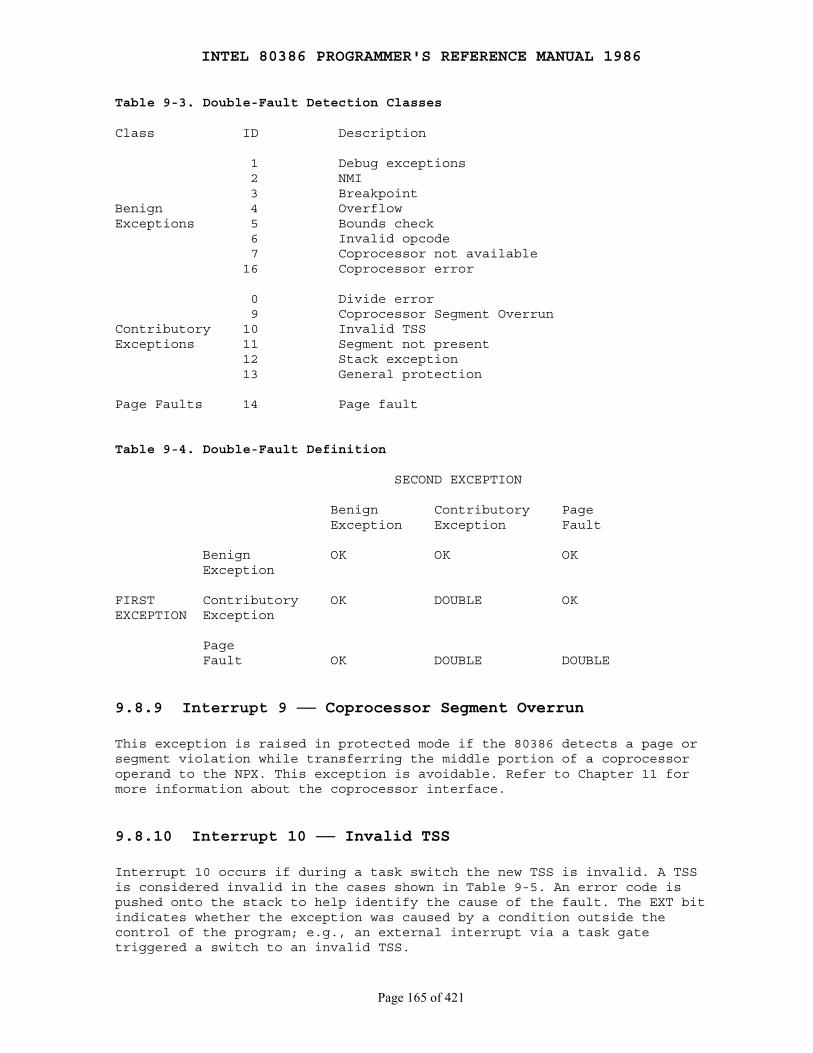
INTEL 80386 PROGRAMMER'S REFERENCE MANUAL 1986
Page 165 of 421
Table 9-3. Double-Fault Detection Classes
Class ID Description
1 Debug exceptions 2 NMI 3 BreakpointBenign 4 OverflowExceptions 5 Bounds check 6 Invalid opcode 7 Coprocessor not available 16 Coprocessor error
0 Divide error 9 Coprocessor Segment OverrunContributory 10 Invalid TSSExceptions 11 Segment not present 12 Stack exception 13 General protection
Page Faults 14 Page fault
Table 9-4. Double-Fault Definition
SECOND EXCEPTION
Benign Contributory Page Exception Exception Fault
Benign OK OK OK Exception
FIRST Contributory OK DOUBLE OKEXCEPTION Exception
Page Fault OK DOUBLE DOUBLE
9.8.9 Interrupt 9 ── Coprocessor Segment OverrunThis exception is raised in protected mode if the 80386 detects a page orsegment violation while transferring the middle portion of a coprocessoroperand to the NPX. This exception is avoidable. Refer to Chapter 11 formore information about the coprocessor interface.
9.8.10 Interrupt 10 ── Invalid TSSInterrupt 10 occurs if during a task switch the new TSS is invalid. A TSSis considered invalid in the cases shown in Table 9-5. An error code ispushed onto the stack to help identify the cause of the fault. The EXT bitindicates whether the exception was caused by a condition outside thecontrol of the program; e.g., an external interrupt via a task gatetriggered a switch to an invalid TSS.
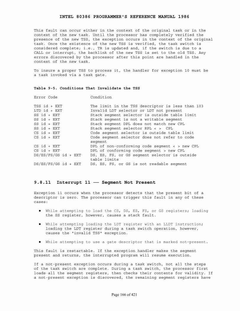
INTEL 80386 PROGRAMMER'S REFERENCE MANUAL 1986
Page 166 of 421
This fault can occur either in the context of the original task or in thecontext of the new task. Until the processor has completely verified thepresence of the new TSS, the exception occurs in the context of the originaltask. Once the existence of the new TSS is verified, the task switch isconsidered complete; i.e., TR is updated and, if the switch is due to aCALL or interrupt, the backlink of the new TSS is set to the old TSS. Anyerrors discovered by the processor after this point are handled in thecontext of the new task.
To insure a proper TSS to process it, the handler for exception 10 must bea task invoked via a task gate.
Table 9-5. Conditions That Invalidate the TSS
Error Code Condition
TSS id + EXT The limit in the TSS descriptor is less than 103LTD id + EXT Invalid LDT selector or LDT not presentSS id + EXT Stack segment selector is outside table limitSS id + EXT Stack segment is not a writable segmentSS id + EXT Stack segment DPL does not match new CPLSS id + EXT Stack segment selector RPL < > CPLCS id + EXT Code segment selector is outside table limitCS id + EXT Code segment selector does not refer to code segmentCS id + EXT DPL of non-conforming code segment < > new CPLCS id + EXT DPL of conforming code segment > new CPLDS/ES/FS/GS id + EXT DS, ES, FS, or GS segment selector is outside table limitsDS/ES/FS/GS id + EXT DS, ES, FS, or GS is not readable segment
9.8.11 Interrupt 11 ── Segment Not PresentException 11 occurs when the processor detects that the present bit of adescriptor is zero. The processor can trigger this fault in any of thesecases:
● While attempting to load the CS, DS, ES, FS, or GS registers; loading the SS register, however, causes a stack fault.
● While attempting loading the LDT register with an LLDT instruction; loading the LDT register during a task switch operation, however, causes the "invalid TSS" exception.
● While attempting to use a gate descriptor that is marked not-present.
This fault is restartable. If the exception handler makes the segmentpresent and returns, the interrupted program will resume execution.
If a not-present exception occurs during a task switch, not all the stepsof the task switch are complete. During a task switch, the processor firstloads all the segment registers, then checks their contents for validity. Ifa not-present exception is discovered, the remaining segment registers have
INTEL 80386 PROGRAMMER'S REFERENCE MANUAL 1986
Page 167 of 421
not been checked and therefore may not be usable for referencing memory. Thenot-present handler should not rely on being able to use the values foundin CS, SS, DS, ES, FS, and GS without causing another exception. Theexception handler should check all segment registers before trying to resumethe new task; otherwise, general protection faults may result later underconditions that make diagnosis more difficult. There are three ways tohandle this case:
1. Handle the not-present fault with a task. The task switch back to the interrupted task will cause the processor to check the registers as it loads them from the TSS.
2. PUSH and POP all segment registers. Each POP causes the processor to check the new contents of the segment register.
3. Scrutinize the contents of each segment-register image in the TSS, simulating the test that the processor makes when it loads a segment register.
This exception pushes an error code onto the stack. The EXT bit of theerror code is set if an event external to the program caused an interruptthat subsequently referenced a not-present segment. The I-bit is set if theerror code refers to an IDT entry, e.g., an INT instruction referencing anot-present gate.
An operating system typically uses the "segment not present" exception toimplement virtual memory at the segment level. A not-present indication in agate descriptor, however, usually does not indicate that a segment is notpresent (because gates do not necessarily correspond to segments).Not-present gates may be used by an operating system to trigger exceptionsof special significance to the operating system.
9.8.12 Interrupt 12 ── Stack ExceptionA stack fault occurs in either of two general conditions:
● As a result of a limit violation in any operation that refers to the SS register. This includes stack-oriented instructions such as POP, PUSH, ENTER, and LEAVE, as well as other memory references that implicitly use SS (for example, MOV AX, [BP+6]). ENTER causes this exception when the stack is too small for the indicated local-variable space.
● When attempting to load the SS register with a descriptor that is marked not-present but is otherwise valid. This can occur in a task switch, an interlevel CALL, an interlevel return, an LSS instruction, or a MOV or POP instruction to SS.
When the processor detects a stack exception, it pushes an error code ontothe stack of the exception handler. If the exception is due to a not-presentstack segment or to overflow of the new stack during an interlevel CALL, theerror code contains a selector to the segment in question (the exceptionhandler can test the present bit in the descriptor to determine whichexception occurred); otherwise the error code is zero.
INTEL 80386 PROGRAMMER'S REFERENCE MANUAL 1986
Page 168 of 421
An instruction that causes this fault is restartable in all cases. Thereturn pointer pushed onto the exception handler's stack points to theinstruction that needs to be restarted. This instruction is usually the onethat caused the exception; however, in the case of a stack exception due toloading of a not-present stack-segment descriptor during a task switch, theindicated instruction is the first instruction of the new task.
When a stack fault occurs during a task switch, the segment registers maynot be usable for referencing memory. During a task switch, the selectorvalues are loaded before the descriptors are checked. If a stack fault isdiscovered, the remaining segment registers have not been checked andtherefore may not be usable for referencing memory. The stack fault handlershould not rely on being able to use the values found in CS, SS, DS, ES,FS, and GS without causing another exception. The exception handler shouldcheck all segment registers before trying to resume the new task; otherwise,general protection faults may result later under conditions that makediagnosis more difficult.
9.8.13 Interrupt 13 ── General Protection ExceptionAll protection violations that do not cause another exception cause ageneral protection exception. This includes (but is not limited to):
1. Exceeding segment limit when using CS, DS, ES, FS, or GS
2. Exceeding segment limit when referencing a descriptor table
3. Transferring control to a segment that is not executable
4. Writing into a read-only data segment or into a code segment
5. Reading from an execute-only segment
6. Loading the SS register with a read-only descriptor (unless the selector comes from the TSS during a task switch, in which case a TSS exception occurs
7. Loading SS, DS, ES, FS, or GS with the descriptor of a system segment
8. Loading DS, ES, FS, or GS with the descriptor of an executable segment that is not also readable
9. Loading SS with the descriptor of an executable segment
10. Accessing memory via DS, ES, FS, or GS when the segment register contains a null selector
11. Switching to a busy task
12. Violating privilege rules
13. Loading CR0 with PG=1 and PE=0.
14. Interrupt or exception via trap or interrupt gate from V86 mode to privilege level other than zero.
INTEL 80386 PROGRAMMER'S REFERENCE MANUAL 1986
Page 169 of 421
15. Exceeding the instruction length limit of 15 bytes (this can occur only if redundant prefixes are placed before an instruction)
The general protection exception is a fault. In response to a generalprotection exception, the processor pushes an error code onto the exceptionhandler's stack. If loading a descriptor causes the exception, the errorcode contains a selector to the descriptor; otherwise, the error code isnull. The source of the selector in an error code may be any of thefollowing:
1. An operand of the instruction. 2. A selector from a gate that is the operand of the instruction. 3. A selector from a TSS involved in a task switch.
9.8.14 Interrupt 14 ── Page FaultThis exception occurs when paging is enabled (PG=1) and the processordetects one of the following conditions while translating a linear addressto a physical address:
● The page-directory or page-table entry needed for the address translation has zero in its present bit.
● The current procedure does not have sufficient privilege to access the indicated page.
The processor makes available to the page fault handler two items ofinformation that aid in diagnosing the exception and recovering from it:
● An error code on the stack. The error code for a page fault has a format different from that for other exceptions (see Figure 9-8). The error code tells the exception handler three things:
1. Whether the exception was due to a not present page or to an access rights violation.
2. Whether the processor was executing at user or supervisor level at the time of the exception.
3. Whether the memory access that caused the exception was a read or write.
● CR2 (control register two). The processor stores in CR2 the linear address used in the access that caused the exception (see Figure 9-9). The exception handler can use this address to locate the corresponding page directory and page table entries. If another page fault can occur during execution of the page fault handler, the handler should push CR2 onto the stack.
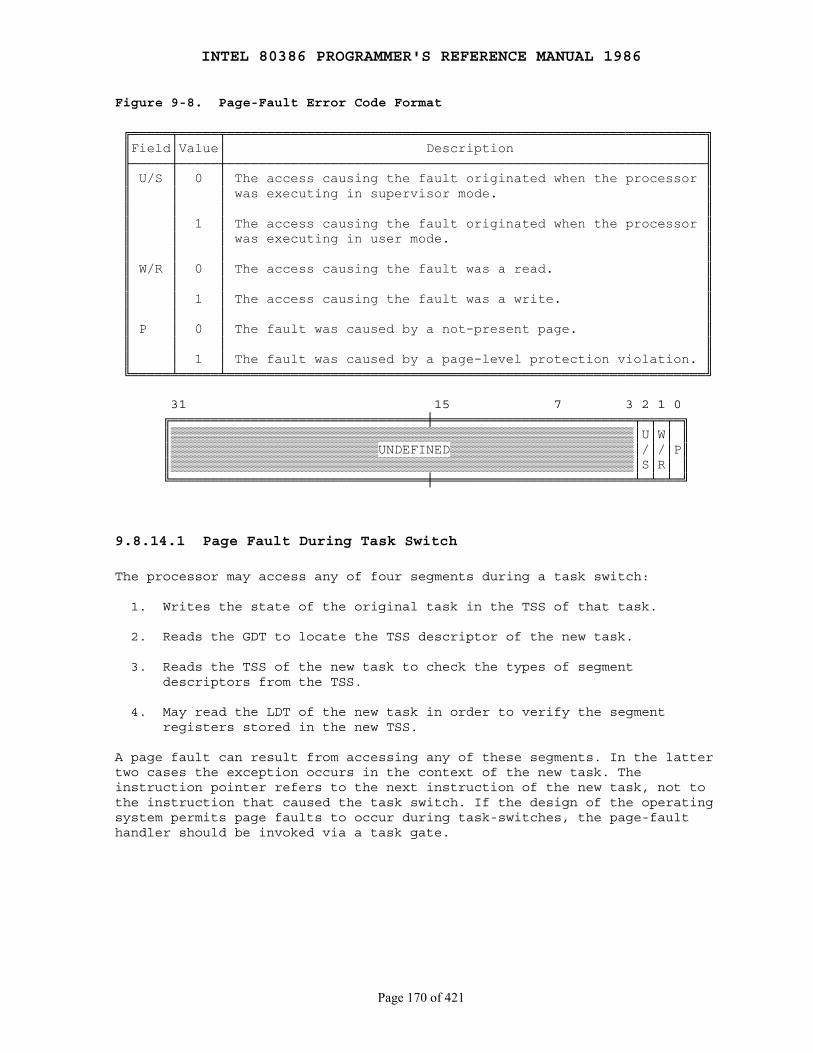
INTEL 80386 PROGRAMMER'S REFERENCE MANUAL 1986
Page 170 of 421
Figure 9-8. Page-Fault Error Code Format
╔═════╤═════╤════════════════════════════════════════════════════════════╗ ║Field│Value│ Description ║ ╟─────┼─────┼────────────────────────────────────────────────────────────╢ ║ U/S │ 0 │ The access causing the fault originated when the processor ║ ║ │ │ was executing in supervisor mode. ║ ║ │ │ ║ ║ │ 1 │ The access causing the fault originated when the processor ║ ║ │ │ was executing in user mode. ║ ║ │ │ ║ ║ W/R │ 0 │ The access causing the fault was a read. ║ ║ │ │ ║ ║ │ 1 │ The access causing the fault was a write. ║ ║ │ │ ║ ║ P │ 0 │ The fault was caused by a not-present page. ║ ║ │ │ ║ ║ │ 1 │ The fault was caused by a page-level protection violation. ║ ╚═════╧═════╧════════════════════════════════════════════════════════════╝
31 15 7 3 2 1 0 ╔════════════════════════════════╪═════════════════════════╤═╤═╤═╗ ║▒▒▒▒▒▒▒▒▒▒▒▒▒▒▒▒▒▒▒▒▒▒▒▒▒▒▒▒▒▒▒▒▒▒▒▒▒▒▒▒▒▒▒▒▒▒▒▒▒▒▒▒▒▒▒▒▒▒│U│W│ ║ ║▒▒▒▒▒▒▒▒▒▒▒▒▒▒▒▒▒▒▒▒▒▒▒▒▒▒UNDEFINED▒▒▒▒▒▒▒▒▒▒▒▒▒▒▒▒▒▒▒▒▒▒▒│/│/│P║ ║▒▒▒▒▒▒▒▒▒▒▒▒▒▒▒▒▒▒▒▒▒▒▒▒▒▒▒▒▒▒▒▒▒▒▒▒▒▒▒▒▒▒▒▒▒▒▒▒▒▒▒▒▒▒▒▒▒▒│S│R│ ║ ╚════════════════════════════════╪═════════════════════════╧═╧═╧═╝
9.8.14.1 Page Fault During Task Switch
The processor may access any of four segments during a task switch:
1. Writes the state of the original task in the TSS of that task.
2. Reads the GDT to locate the TSS descriptor of the new task.
3. Reads the TSS of the new task to check the types of segment descriptors from the TSS.
4. May read the LDT of the new task in order to verify the segment registers stored in the new TSS.
A page fault can result from accessing any of these segments. In the lattertwo cases the exception occurs in the context of the new task. Theinstruction pointer refers to the next instruction of the new task, not tothe instruction that caused the task switch. If the design of the operatingsystem permits page faults to occur during task-switches, the page-faulthandler should be invoked via a task gate.

INTEL 80386 PROGRAMMER'S REFERENCE MANUAL 1986
Page 171 of 421
Figure 9-9. CR2 Format
31 23 15 7 0 ╔════════════════╪════════════════╪════════════════╪════════════════╗ ║ ║ ║ PAGE FAULT LINEAR ADDRESS ║ ║ ║ ╚════════════════╪════════════════╪════════════════╪════════════════╝
9.8.14.2 Page Fault with Inconsistent Stack Pointer
Special care should be taken to ensure that a page fault does not cause theprocessor to use an invalid stack pointer (SS:ESP). Software written forearlier processors in the 8086 family often uses a pair of instructions tochange to a new stack; for example:
MOV SS, AXMOV SP, StackTop
With the 80386, because the second instruction accesses memory, it ispossible to get a page fault after SS has been changed but before SP hasreceived the corresponding change. At this point, the two parts of the stackpointer SS:SP (or, for 32-bit programs, SS:ESP) are inconsistent.
The processor does not use the inconsistent stack pointer if the handlingof the page fault causes a stack switch to a well defined stack (i.e., thehandler is a task or a more privileged procedure). However, if the pagefault handler is invoked by a trap or interrupt gate and the page faultoccurs at the same privilege level as the page fault handler, the processorwill attempt to use the stack indicated by the current (invalid) stackpointer.
In systems that implement paging and that handle page faults within thefaulting task (with trap or interrupt gates), software that executes at thesame privilege level as the page fault handler should initialize a new stackby using the new LSS instruction rather than an instruction pair shownabove. When the page fault handler executes at privilege level zero (thenormal case), the scope of the problem is limited to privilege-level zerocode, typically the kernel of the operating system.
9.8.15 Interrupt 16 ── Coprocessor ErrorThe 80386 reports this exception when it detects a signal from the 80287 or80387 on the 80386's ERROR# input pin. The 80386 tests this pin only at thebeginning of certain ESC instructions and when it encounters a WAITinstruction while the EM bit of the MSW is zero (no emulation). Refer toChapter 11 for more information on the coprocessor interface.
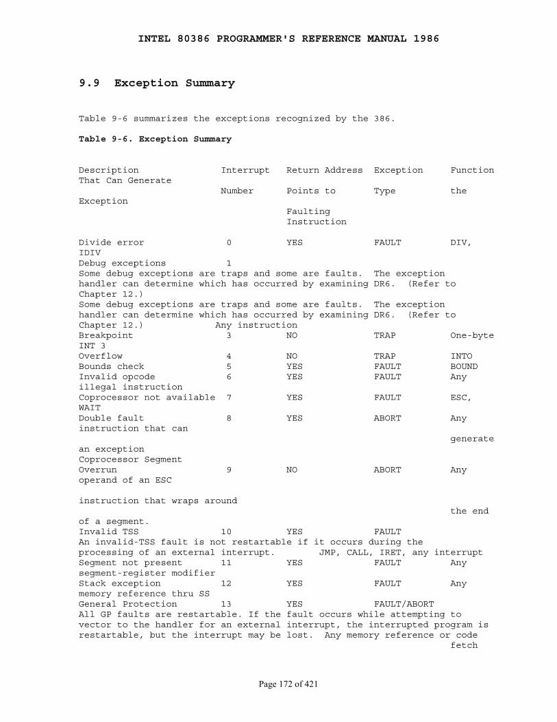
INTEL 80386 PROGRAMMER'S REFERENCE MANUAL 1986
Page 172 of 421
9.9 Exception Summary
Table 9-6 summarizes the exceptions recognized by the 386.
Table 9-6. Exception Summary
Description Interrupt Return Address Exception FunctionThat Can Generate Number Points to Type theException Faulting Instruction
Divide error 0 YES FAULT DIV,IDIVDebug exceptions 1Some debug exceptions are traps and some are faults. The exceptionhandler can determine which has occurred by examining DR6. (Refer toChapter 12.)Some debug exceptions are traps and some are faults. The exceptionhandler can determine which has occurred by examining DR6. (Refer toChapter 12.) Any instructionBreakpoint 3 NO TRAP One-byteINT 3Overflow 4 NO TRAP INTOBounds check 5 YES FAULT BOUNDInvalid opcode 6 YES FAULT Anyillegal instructionCoprocessor not available 7 YES FAULT ESC,WAITDouble fault 8 YES ABORT Anyinstruction that can generatean exceptionCoprocessor SegmentOverrun 9 NO ABORT Anyoperand of an ESC
instruction that wraps around the endof a segment.Invalid TSS 10 YES FAULTAn invalid-TSS fault is not restartable if it occurs during theprocessing of an external interrupt. JMP, CALL, IRET, any interruptSegment not present 11 YES FAULT Anysegment-register modifierStack exception 12 YES FAULT Anymemory reference thru SSGeneral Protection 13 YES FAULT/ABORTAll GP faults are restartable. If the fault occurs while attempting tovector to the handler for an external interrupt, the interrupted program isrestartable, but the interrupt may be lost. Any memory reference or code fetch

INTEL 80386 PROGRAMMER'S REFERENCE MANUAL 1986
Page 173 of 421
Page fault 14 YES FAULT Anymemory reference or code fetchCoprocessor error 16 YES FAULTCoprocessor errors are reported as a fault on the first ESC or WAITinstruction executed after the ESC instruction that caused the error.ESC, WAITTwo-byte SW Interrupt 0-255 NO TRAP INT n
9.10 Error Code Summary
Table 9-7 summarizes the error information that is available with eachexception.
Table 9-7. Error-Code Summary
Description Interrupt Error Code Number
Divide error 0 NoDebug exceptions 1 NoBreakpoint 3 NoOverflow 4 NoBounds check 5 NoInvalid opcode 6 NoCoprocessor not available 7 NoSystem error 8 Yes (always 0)Coprocessor Segment Overrun 9 NoInvalid TSS 10 YesSegment not present 11 YesStack exception 12 YesGeneral protection fault 13 YesPage fault 14 YesCoprocessor error 16 NoTwo-byte SW interrupt 0-255 No
INTEL 80386 PROGRAMMER'S REFERENCE MANUAL 1986
Page 174 of 421
Chapter 10 Initialization
────────────────────────────────────────────────────────────────────────────
After a signal on the RESET pin, certain registers of the 80386 are set topredefined values. These values are adequate to enable execution of abootstrap program, but additional initialization must be performed bysoftware before all the features of the processor can be utilized.
10.1 Processor State After Reset
The contents of EAX depend upon the results of the power-up self test. Theself-test may be requested externally by assertion of BUSY# at the end ofRESET. The EAX register holds zero if the 80386 passed the test. A nonzerovalue in EAX after self-test indicates that the particular 80386 unit isfaulty. If the self-test is not requested, the contents of EAX after RESETis undefined.
DX holds a component identifier and revision number after RESET as Figure10-1 illustrates. DH contains 3, which indicates an 80386 component. DLcontains a unique identifier of the revision level.
Control register zero (CR0) contains the values shown in Figure 10-2. TheET bit of CR0 is set if an 80387 is present in the configuration (accordingto the state of the ERROR# pin after RESET). If ET is reset, theconfiguration either contains an 80287 or does not contain a coprocessor. Asoftware test is required to distinguish between these latter twopossibilities.
The remaining registers and flags are set as follows:
EFLAGS =00000002H IP =0000FFF0H CS selector =000H DS selector =0000H ES selector =0000H SS selector =0000H FS selector =0000H GS selector =0000H IDTR: base =0 limit =03FFH
All registers not mentioned above are undefined.
These settings imply that the processor begins in real-address mode withinterrupts disabled.
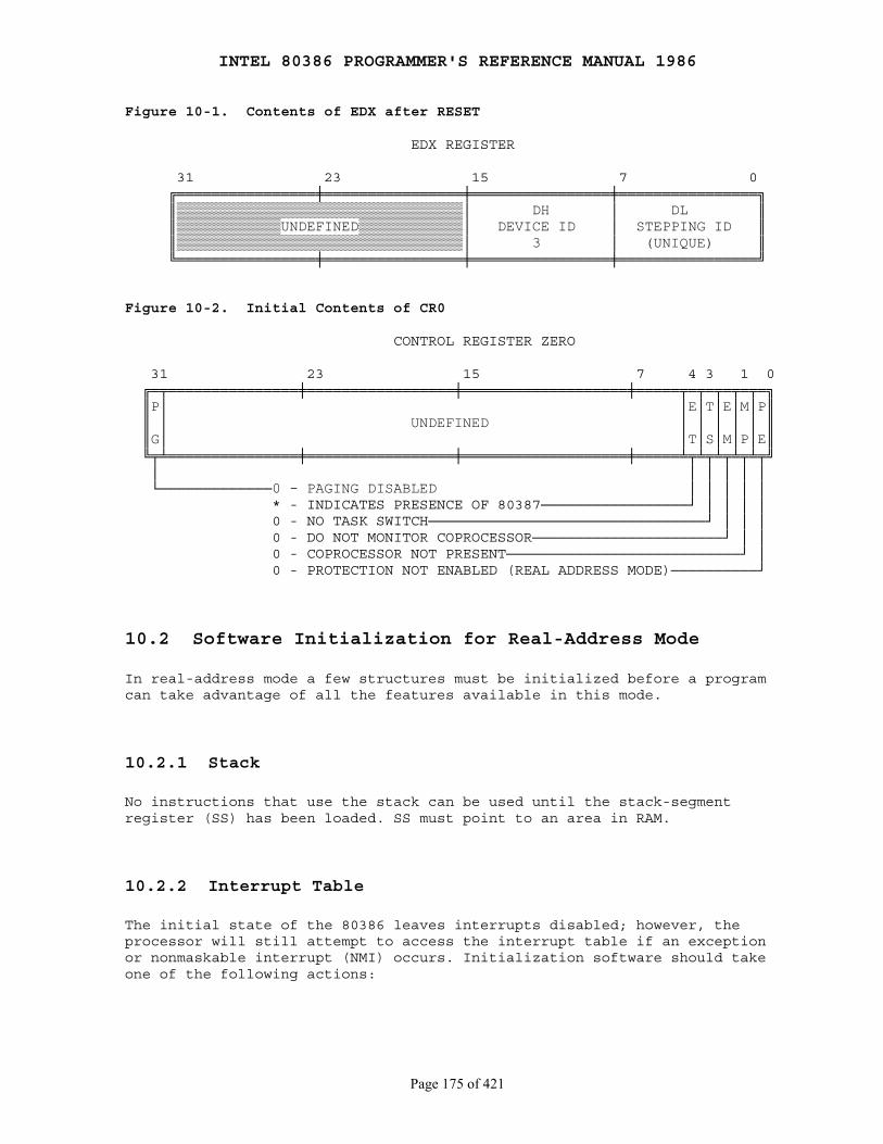
INTEL 80386 PROGRAMMER'S REFERENCE MANUAL 1986
Page 175 of 421
Figure 10-1. Contents of EDX after RESET
EDX REGISTER
31 23 15 7 0 ╔════════════════╪════════════════╪════════════════╪════════════════╗ ║▒▒▒▒▒▒▒▒▒▒▒▒▒▒▒▒▒▒▒▒▒▒▒▒▒▒▒▒▒▒▒▒▒│ DH │ DL ║ ║▒▒▒▒▒▒▒▒▒▒▒▒UNDEFINED▒▒▒▒▒▒▒▒▒▒▒▒│ DEVICE ID │ STEPPING ID ║ ║▒▒▒▒▒▒▒▒▒▒▒▒▒▒▒▒▒▒▒▒▒▒▒▒▒▒▒▒▒▒▒▒▒│ 3 │ (UNIQUE) ║ ╚════════════════╪════════════════╪════════════════╪════════════════╝
Figure 10-2. Initial Contents of CR0
CONTROL REGISTER ZERO
31 23 15 7 4 3 1 0 ╔═╤═══════════════╪═════════════════╪═══════════════════╪═════╤═╤═╤═╤═╤═╗ ║P│ │E│T│E│M│P║ ║ │ UNDEFINED │ │ │ │ │ ║ ║G│ │T│S│M│P│E║ ╚╤╧═══════════════╪═════════════════╪═══════════════════╪═════╧╤╧╤╧╤╧╤╧╤╝ │ │ │ │ │ │ └─────────────0 - PAGING DISABLED │ │ │ │ │ * - INDICATES PRESENCE OF 80387─────────────────┘ │ │ │ │ 0 - NO TASK SWITCH────────────────────────────────┘ │ │ │ 0 - DO NOT MONITOR COPROCESSOR──────────────────────┘ │ │ 0 - COPROCESSOR NOT PRESENT───────────────────────────┘ │ 0 - PROTECTION NOT ENABLED (REAL ADDRESS MODE)──────────┘
10.2 Software Initialization for Real-Address Mode
In real-address mode a few structures must be initialized before a programcan take advantage of all the features available in this mode.
10.2.1 Stack
No instructions that use the stack can be used until the stack-segmentregister (SS) has been loaded. SS must point to an area in RAM.
10.2.2 Interrupt Table
The initial state of the 80386 leaves interrupts disabled; however, theprocessor will still attempt to access the interrupt table if an exceptionor nonmaskable interrupt (NMI) occurs. Initialization software should takeone of the following actions:
INTEL 80386 PROGRAMMER'S REFERENCE MANUAL 1986
Page 176 of 421
● Change the limit value in the IDTR to zero. This will cause a shutdown if an exception or nonmaskable interrupt occurs. (Refer to the 80386 Hardware Reference Manual to see how shutdown is signalled externally.)
● Put pointers to valid interrupt handlers in all positions of the interrupt table that might be used by exceptions or interrupts.
● Change the IDTR to point to a valid interrupt table.
10.2.3 First Instructions
After RESET, address lines A{31-20} are automatically asserted forinstruction fetches. This fact, together with the initial values of CS:IP,causes instruction execution to begin at physical address FFFFFFF0H. Near(intrasegment) forms of control transfer instructions may be used to passcontrol to other addresses in the upper 64K bytes of the address space. Thefirst far (intersegment) JMP or CALL instruction causes A{31-20} to droplow, and the 80386 continues executing instructions in the lower onemegabyte of physical memory. This automatic assertion of address linesA{31-20} allows systems designers to use a ROM at the high end ofthe address space to initialize the system.
10.3 Switching to Protected Mode
Setting the PE bit of the MSW in CR0 causes the 80386 to begin executing inprotected mode. The current privilege level (CPL) starts at zero. Thesegment registers continue to point to the same linear addresses as in realaddress mode (in real address mode, linear addresses are the same physicaladdresses).
Immediately after setting the PE flag, the initialization code must flushthe processor's instruction prefetch queue by executing a JMP instruction.The 80386 fetches and decodes instructions and addresses before they areused; however, after a change into protected mode, the prefetchedinstruction information (which pertains to real-address mode) is no longervalid. A JMP forces the processor to discard the invalid information.
10.4 Software Initialization for Protected Mode
Most of the initialization needed for protected mode can be done eitherbefore or after switching to protected mode. If done in protected mode,however, the initialization procedures must not use protected-mode featuresthat are not yet initialized.
INTEL 80386 PROGRAMMER'S REFERENCE MANUAL 1986
Page 177 of 421
10.4.1 Interrupt Descriptor Table
The IDTR may be loaded in either real-address or protected mode. However,the format of the interrupt table for protected mode is different than thatfor real-address mode. It is not possible to change to protected mode andchange interrupt table formats at the same time; therefore, it is inevitablethat, if IDTR selects an interrupt table, it will have the wrong format atsome time. An interrupt or exception that occurs at this time will haveunpredictable results. To avoid this unpredictability, interrupts shouldremain disabled until interrupt handlers are in place and a valid IDT hasbeen created in protected mode.
10.4.2 Stack
The SS register may be loaded in either real-address mode or protectedmode. If loaded in real-address mode, SS continues to point to the samelinear base-address after the switch to protected mode.
10.4.3 Global Descriptor Table
Before any segment register is changed in protected mode, the GDT registermust point to a valid GDT. Initialization of the GDT and GDTR may be done inreal-address mode. The GDT (as well as LDTs) should reside in RAM, becausethe processor modifies the accessed bit of descriptors.
10.4.4 Page Tables
Page tables and the PDBR in CR3 can be initialized in either real-addressmode or in protected mode; however, the paging enabled (PG) bit of CR0cannot be set until the processor is in protected mode. PG may be setsimultaneously with PE, or later. When PG is set, the PDBR in CR3 shouldalready be initialized with a physical address that points to a valid pagedirectory. The initialization procedure should adopt one of the followingstrategies to ensure consistent addressing before and after paging isenabled:
● The page that is currently being executed should map to the same physical addresses both before and after PG is set.
● A JMP instruction should immediately follow the setting of PG.

INTEL 80386 PROGRAMMER'S REFERENCE MANUAL 1986
Page 178 of 421
10.4.5 First Task
The initialization procedure can run awhile in protected mode withoutinitializing the task register; however, before the first task switch, thefollowing conditions must prevail:
● There must be a valid task state segment (TSS) for the new task. The stack pointers in the TSS for privilege levels numerically less than or equal to the initial CPL must point to valid stack segments.
● The task register must point to an area in which to save the current task state. After the first task switch, the information dumped in this area is not needed, and the area can be used for other purposes.
10.5 Initialization Example
$TITLE ('Initial Task')
NAME INIT
init_stack SEGMENT RW DW 20 DUP(?)tos LABEL WORDinit_stack ENDS
init_data SEGMENT RW PUBLIC DW 20 DUP(?)init_data ENDS
init_code SEGMENT ER PUBLIC
ASSUME DS:init_data
nop nop nopinit_start: ; set up stack mov ax, init_stack mov ss, ax mov esp, offset tos
mov a1,1blink: xor a1,1 out 0e4h,a1 mov cx,3FFFhhere: dec cx jnz here
jmp SHORT blink

INTEL 80386 PROGRAMMER'S REFERENCE MANUAL 1986
Page 179 of 421
hltinit_code ends
END init_start, SS:init_stack, DS:init_data
$TITLE('Protected Mode Transition -- 386 initialization')NAME RESET
;*****************************************************************; Upon reset the 386 starts executing at address 0FFFFFFF0H. The; upper 12 address bits remain high until a FAR call or jump is; executed.;; Assume the following:;;; - a short jump at address 0FFFFFFF0H (placed there by the; system builder) causes execution to begin at START in segment; RESET_CODE.;;; - segment RESET_CODE is based at physical address 0FFFF0000H,; i.e. at the start of the last 64K in the 4G address space.; Note that this is the base of the CS register at reset. If; you locate ROMcode above this address, you will need to; figure out an adjustment factor to address things within this; segment.;;*****************************************************************$EJECT ;
; Define addresses to locate GDT and IDT in RAM.; These addresses are also used in the BLD386 file that defines; the GDT and IDT. If you change these addresses, make sure you; change the base addresses specified in the build file.
GDTbase EQU 00001000H ; physical address for GDT baseIDTbase EQU 00000400H ; physical address for IDT base
PUBLIC GDT_EPROMPUBLIC IDT_EPROMPUBLIC START
DUMMY segment rw ; ONLY for ASM386 main module stack init DW 0DUMMY ends
;*****************************************************************;; Note: RESET CODE must be USEl6 because the 386 initally executes; in real mode.;
RESET_CODE segment er PUBLIC USE16
ASSUME DS:nothing, ES:nothing
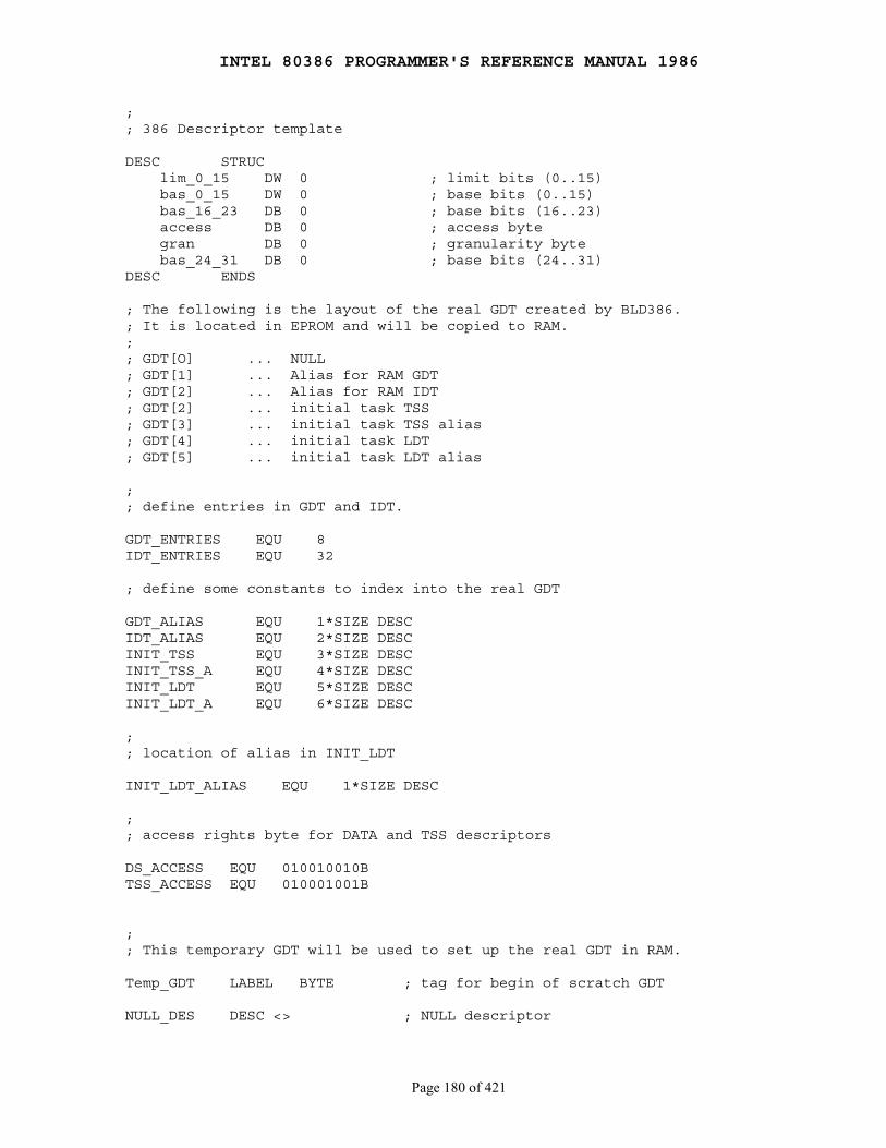
INTEL 80386 PROGRAMMER'S REFERENCE MANUAL 1986
Page 180 of 421
;; 386 Descriptor template
DESC STRUC lim_0_15 DW 0 ; limit bits (0..15) bas_0_15 DW 0 ; base bits (0..15) bas_16_23 DB 0 ; base bits (16..23) access DB 0 ; access byte gran DB 0 ; granularity byte bas_24_31 DB 0 ; base bits (24..31)DESC ENDS
; The following is the layout of the real GDT created by BLD386.; It is located in EPROM and will be copied to RAM.;; GDT[O] ... NULL; GDT[1] ... Alias for RAM GDT; GDT[2] ... Alias for RAM IDT; GDT[2] ... initial task TSS; GDT[3] ... initial task TSS alias; GDT[4] ... initial task LDT; GDT[5] ... initial task LDT alias
;; define entries in GDT and IDT.
GDT_ENTRIES EQU 8IDT_ENTRIES EQU 32
; define some constants to index into the real GDT
GDT_ALIAS EQU 1*SIZE DESCIDT_ALIAS EQU 2*SIZE DESCINIT_TSS EQU 3*SIZE DESCINIT_TSS_A EQU 4*SIZE DESCINIT_LDT EQU 5*SIZE DESCINIT_LDT_A EQU 6*SIZE DESC
;; location of alias in INIT_LDT
INIT_LDT_ALIAS EQU 1*SIZE DESC
;; access rights byte for DATA and TSS descriptors
DS_ACCESS EQU 010010010BTSS_ACCESS EQU 010001001B
;; This temporary GDT will be used to set up the real GDT in RAM.
Temp_GDT LABEL BYTE ; tag for begin of scratch GDT
NULL_DES DESC <> ; NULL descriptor
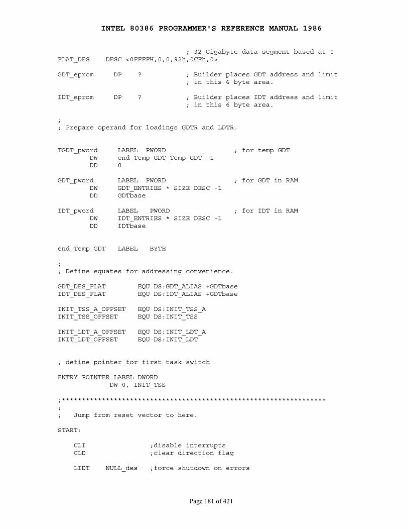
INTEL 80386 PROGRAMMER'S REFERENCE MANUAL 1986
Page 181 of 421
; 32-Gigabyte data segment based at 0FLAT_DES DESC <0FFFFH,0,0,92h,0CFh,0>
GDT_eprom DP ? ; Builder places GDT address and limit ; in this 6 byte area.
IDT_eprom DP ? ; Builder places IDT address and limit ; in this 6 byte area.
;; Prepare operand for loadings GDTR and LDTR.
TGDT_pword LABEL PWORD ; for temp GDT DW end_Temp_GDT_Temp_GDT -1 DD 0
GDT_pword LABEL PWORD ; for GDT in RAM DW GDT_ENTRIES * SIZE DESC -1 DD GDTbase
IDT_pword LABEL PWORD ; for IDT in RAM DW IDT_ENTRIES * SIZE DESC -1 DD IDTbase
end_Temp_GDT LABEL BYTE
;; Define equates for addressing convenience.
GDT_DES_FLAT EQU DS:GDT_ALIAS +GDTbaseIDT_DES_FLAT EQU DS:IDT_ALIAS +GDTbase
INIT_TSS_A_OFFSET EQU DS:INIT_TSS_AINIT_TSS_OFFSET EQU DS:INIT_TSS
INIT_LDT_A_OFFSET EQU DS:INIT_LDT_AINIT_LDT_OFFSET EQU DS:INIT_LDT
; define pointer for first task switch
ENTRY POINTER LABEL DWORD DW 0, INIT_TSS
;******************************************************************;; Jump from reset vector to here.
START:
CLI ;disable interrupts CLD ;clear direction flag
LIDT NULL_des ;force shutdown on errors
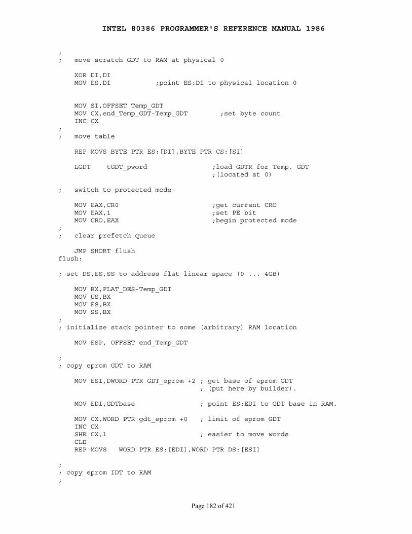
INTEL 80386 PROGRAMMER'S REFERENCE MANUAL 1986
Page 182 of 421
;; move scratch GDT to RAM at physical 0
XOR DI,DI MOV ES,DI ;point ES:DI to physical location 0
MOV SI,OFFSET Temp_GDT MOV CX,end_Temp_GDT-Temp_GDT ;set byte count INC CX;; move table
REP MOVS BYTE PTR ES:[DI],BYTE PTR CS:[SI]
LGDT tGDT_pword ;load GDTR for Temp. GDT ;(located at 0)
; switch to protected mode
MOV EAX,CR0 ;get current CRO MOV EAX,1 ;set PE bit MOV CRO,EAX ;begin protected mode;; clear prefetch queue
JMP SHORT flushflush:
; set DS,ES,SS to address flat linear space (0 ... 4GB)
MOV BX,FLAT_DES-Temp_GDT MOV US,BX MOV ES,BX MOV SS,BX;; initialize stack pointer to some (arbitrary) RAM location
MOV ESP, OFFSET end_Temp_GDT
;; copy eprom GDT to RAM
MOV ESI,DWORD PTR GDT_eprom +2 ; get base of eprom GDT ; (put here by builder).
MOV EDI,GDTbase ; point ES:EDI to GDT base in RAM.
MOV CX,WORD PTR gdt_eprom +0 ; limit of eprom GDT INC CX SHR CX,1 ; easier to move words CLD REP MOVS WORD PTR ES:[EDI],WORD PTR DS:[ESI]
;; copy eprom IDT to RAM;
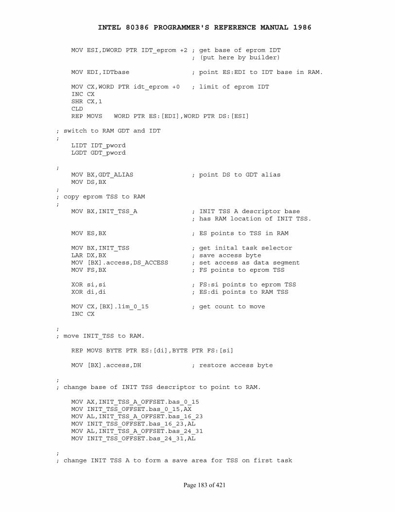
INTEL 80386 PROGRAMMER'S REFERENCE MANUAL 1986
Page 183 of 421
MOV ESI,DWORD PTR IDT_eprom +2 ; get base of eprom IDT ; (put here by builder)
MOV EDI,IDTbase ; point ES:EDI to IDT base in RAM.
MOV CX,WORD PTR idt_eprom +0 ; limit of eprom IDT INC CX SHR CX,1 CLD REP MOVS WORD PTR ES:[EDI],WORD PTR DS:[ESI]
; switch to RAM GDT and IDT; LIDT IDT_pword LGDT GDT_pword
; MOV BX,GDT_ALIAS ; point DS to GDT alias MOV DS,BX;; copy eprom TSS to RAM; MOV BX,INIT_TSS_A ; INIT TSS A descriptor base ; has RAM location of INIT TSS.
MOV ES,BX ; ES points to TSS in RAM
MOV BX,INIT_TSS ; get inital task selector LAR DX,BX ; save access byte MOV [BX].access,DS_ACCESS ; set access as data segment MOV FS,BX ; FS points to eprom TSS
XOR si,si ; FS:si points to eprom TSS XOR di,di ; ES:di points to RAM TSS
MOV CX,[BX].lim_0_15 ; get count to move INC CX
;; move INIT_TSS to RAM.
REP MOVS BYTE PTR ES:[di],BYTE PTR FS:[si]
MOV [BX].access,DH ; restore access byte
;; change base of INIT TSS descriptor to point to RAM.
MOV AX,INIT_TSS_A_OFFSET.bas_0_15 MOV INIT_TSS_OFFSET.bas_0_15,AX MOV AL,INIT_TSS_A_OFFSET.bas_16_23 MOV INIT_TSS_OFFSET.bas_16_23,AL MOV AL,INIT_TSS_A_OFFSET.bas_24_31 MOV INIT_TSS_OFFSET.bas_24_31,AL
;; change INIT TSS A to form a save area for TSS on first task
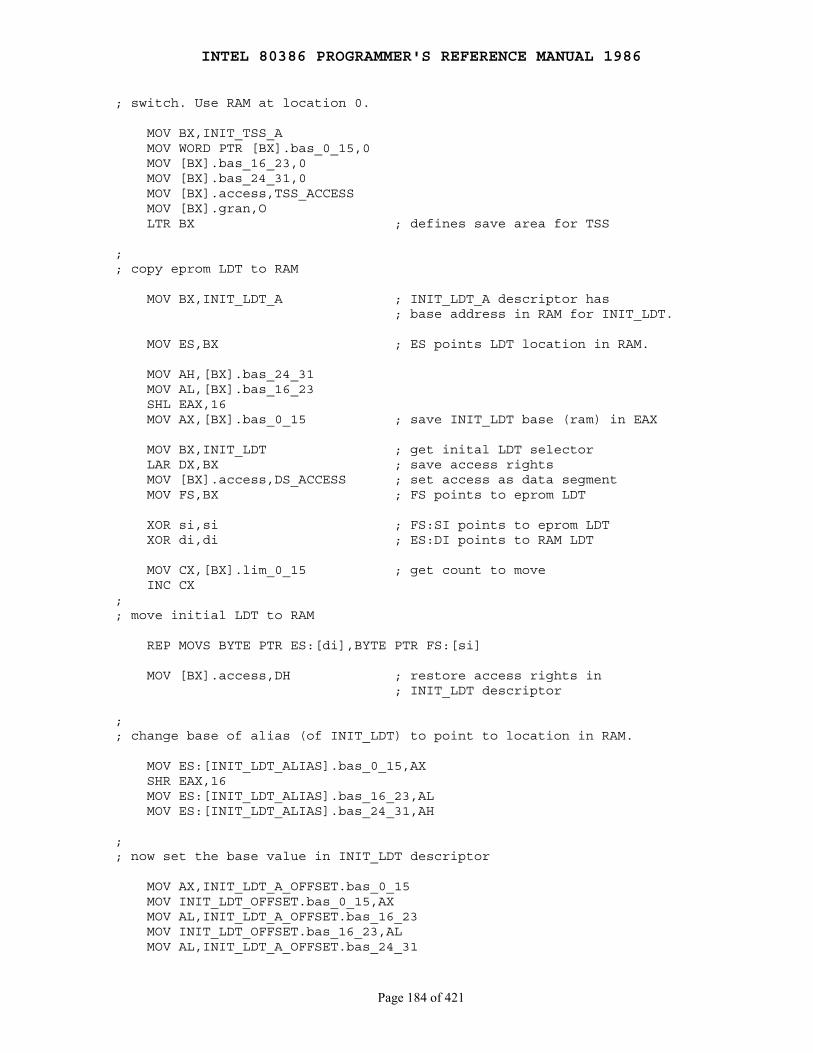
INTEL 80386 PROGRAMMER'S REFERENCE MANUAL 1986
Page 184 of 421
; switch. Use RAM at location 0.
MOV BX,INIT_TSS_A MOV WORD PTR [BX].bas_0_15,0 MOV [BX].bas_16_23,0 MOV [BX].bas_24_31,0 MOV [BX].access,TSS_ACCESS MOV [BX].gran,O LTR BX ; defines save area for TSS
;; copy eprom LDT to RAM
MOV BX,INIT_LDT_A ; INIT_LDT_A descriptor has ; base address in RAM for INIT_LDT.
MOV ES,BX ; ES points LDT location in RAM.
MOV AH,[BX].bas_24_31 MOV AL,[BX].bas_16_23 SHL EAX,16 MOV AX,[BX].bas_0_15 ; save INIT_LDT base (ram) in EAX
MOV BX,INIT_LDT ; get inital LDT selector LAR DX,BX ; save access rights MOV [BX].access,DS_ACCESS ; set access as data segment MOV FS,BX ; FS points to eprom LDT
XOR si,si ; FS:SI points to eprom LDT XOR di,di ; ES:DI points to RAM LDT
MOV CX,[BX].lim_0_15 ; get count to move INC CX;; move initial LDT to RAM
REP MOVS BYTE PTR ES:[di],BYTE PTR FS:[si]
MOV [BX].access,DH ; restore access rights in ; INIT_LDT descriptor
;; change base of alias (of INIT_LDT) to point to location in RAM.
MOV ES:[INIT_LDT_ALIAS].bas_0_15,AX SHR EAX,16 MOV ES:[INIT_LDT_ALIAS].bas_16_23,AL MOV ES:[INIT_LDT_ALIAS].bas_24_31,AH
;; now set the base value in INIT_LDT descriptor
MOV AX,INIT_LDT_A_OFFSET.bas_0_15 MOV INIT_LDT_OFFSET.bas_0_15,AX MOV AL,INIT_LDT_A_OFFSET.bas_16_23 MOV INIT_LDT_OFFSET.bas_16_23,AL MOV AL,INIT_LDT_A_OFFSET.bas_24_31

INTEL 80386 PROGRAMMER'S REFERENCE MANUAL 1986
Page 185 of 421
MOV INIT_LDT_OFFSET.bas_24_31,AL
;; Now GDT, IDT, initial TSS and initial LDT are all set up.;; Start the first task!' JMP ENTRY_POINTER
RESET_CODE ends END START, SS:DUMMY,DS:DUMMY
10.6 TLB Testing
The 80386 provides a mechanism for testing the Translation Lookaside Buffer(TLB), the cache used for translating linear addresses to physicaladdresses. Although failure of the TLB hardware is extremely unlikely, usersmay wish to include TLB confidence tests among other power-up confidencetests for the 80386.
───────────────────────────────────────────────────────────────────────────NOTE This TLB testing mechanism is unique to the 80386 and may not be continued in the same way in future processors. Sortware that uses this mechanism may be incompatible with future processors.───────────────────────────────────────────────────────────────────────────
When testing the TLB it is recommended that paging be turned off (PG=0 inCR0) to avoid interference with the test data being written to the TLB.
10.6.1 Structure of the TLB
The TLB is a four-way set-associative memory. Figure 10-3 illustrates thestructure of the TLB. There are four sets of eight entries each. Each entryconsists of a tag and data. Tags are 24-bits wide. They contain thehigh-order 20 bits of the linear address, the valid bit, and three attributebits. The data portion of each entry contains the high-order 20 bits of thephysical address.
10.6.2 Test Registers
Two test registers, shown in Figure 10-4, are provided for the purpose oftesting. TR6 is the test command register, and TR7 is the test dataregister. These registers are accessed by variants of the MOVinstruction. A test register may be either the source operand or destinationoperand. The MOV instructions are defined in both real-address mode andprotected mode. The test registers are privileged resources; in protectedmode, the MOV instructions that access them can only be executed atprivilege level 0. An attempt to read or write the test registers whenexecuting at any other privilege level causes a generalprotection exception.
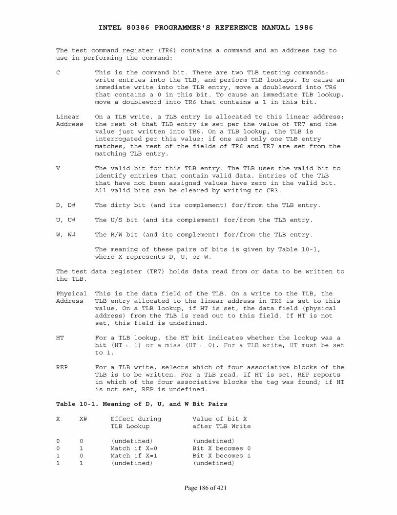
INTEL 80386 PROGRAMMER'S REFERENCE MANUAL 1986
Page 186 of 421
The test command register (TR6) contains a command and an address tag touse in performing the command:
C This is the command bit. There are two TLB testing commands: write entries into the TLB, and perform TLB lookups. To cause an immediate write into the TLB entry, move a doubleword into TR6 that contains a 0 in this bit. To cause an immediate TLB lookup, move a doubleword into TR6 that contains a 1 in this bit.
Linear On a TLB write, a TLB entry is allocated to this linear address;Address the rest of that TLB entry is set per the value of TR7 and the value just written into TR6. On a TLB lookup, the TLB is interrogated per this value; if one and only one TLB entry matches, the rest of the fields of TR6 and TR7 are set from the matching TLB entry.
V The valid bit for this TLB entry. The TLB uses the valid bit to identify entries that contain valid data. Entries of the TLB that have not been assigned values have zero in the valid bit. All valid bits can be cleared by writing to CR3.
D, D# The dirty bit (and its complement) for/from the TLB entry.
U, U# The U/S bit (and its complement) for/from the TLB entry.
W, W# The R/W bit (and its complement) for/from the TLB entry.
The meaning of these pairs of bits is given by Table 10-1, where X represents D, U, or W.
The test data register (TR7) holds data read from or data to be written tothe TLB.
Physical This is the data field of the TLB. On a write to the TLB, theAddress TLB entry allocated to the linear address in TR6 is set to this value. On a TLB lookup, if HT is set, the data field (physical address) from the TLB is read out to this field. If HT is not set, this field is undefined.
HT For a TLB lookup, the HT bit indicates whether the lookup was a hit (HT ← 1) or a miss (HT ← 0). For a TLB write, HT must be set to 1.
REP For a TLB write, selects which of four associative blocks of the TLB is to be written. For a TLB read, if HT is set, REP reports in which of the four associative blocks the tag was found; if HT is not set, REP is undefined.
Table 10-1. Meaning of D, U, and W Bit Pairs
X X# Effect during Value of bit X TLB Lookup after TLB Write
0 0 (undefined) (undefined)0 1 Match if X=0 Bit X becomes 01 0 Match if X=1 Bit X becomes 11 1 (undefined) (undefined)

INTEL 80386 PROGRAMMER'S REFERENCE MANUAL 1986
Page 187 of 421
Figure 10-3. TLB Structure
╔═════════════════╦════════════════╗ 7║ TAG ║ DATA ║ ╠═════════════════╬════════════════╣ · · · ┌─────── · · · │ SET 11 · · · │ ┌── ╠═════════════════╬════════════════╣ │ │ 1║ TAG ║ DATA ║ │ │ ╠═════════════════╬════════════════╣ │ │ 0║ TAG ║ DATA ║ │ │ ╚═════════════════╩════════════════╝ │ │ │ │ ╔═════════════════╦════════════════╗ │ │ 7║ TAG ║ DATA ║ │ │ ╠═════════════════╬════════════════╣ │ │ · · · │ └── · · · │ SET 10 · · · │ ┌── ╠═════════════════╬════════════════╣ │ │ 1║ TAG ║ DATA ║ │ D │ │ │ ╠═════════════════╬════════════════╣ │ A │ │ │ 0║ TAG ║ DATA ║ │ T └──────┘ │ ╚═════════════════╩════════════════╝ │ A │ │ ┌──────┐ │ ╔═════════════════╦════════════════╗ │ B │ │ │ 7║ TAG ║ DATA ║ │ U │ │ │ ╠═════════════════╬════════════════╣ │ S │ │ │ · · · │ └── · · · │ SET 01 · · · │ ┌── ╠═════════════════╬════════════════╣ │ │ 1║ TAG ║ DATA ║ │ │ ╠═════════════════╬════════════════╣ │ │ 0║ TAG ║ DATA ║ │ │ ╚═════════════════╩════════════════╝ │ │ │ │ ╔═════════════════╦════════════════╗ │ │ 7║ TAG ║ DATA ║ │ │ ╠═════════════════╬════════════════╣ │ │ · · · │ └── · · · │ SET 00 · · · └─────── ╠═════════════════╬════════════════╣ 1║ TAG ║ DATA ║ ╠═════════════════╬════════════════╣ 0║ TAG ║ DATA ║ ╚═════════════════╩════════════════╝

INTEL 80386 PROGRAMMER'S REFERENCE MANUAL 1986
Page 188 of 421
Figure 10-4. Test Registers
31 23 15 11 7 0 ╔═════════════════╪═══════════════╪════╪═══════╪═════╤═╤═══╤═══╗ ║ │ │H│ │ ║ ║ PHYSICAL ADDRESS │0 0 0 0 0 0 0│ │REP│0 0║ TR7 ║ │ │T│ │ ║ ╟──────────────────────────────────────┼─┬─┬─┬─┬─┬─┬─┼─┴───┴─┬─╢ ║ │ │ │D│ │U│ │W│ │ ║ ║ LINEAR ADDRESS │V│D│ │U│ │ │ │0 0 0 0│C║ TR8 ║ │ │ │#│ │#│ │#│ │ ║ ╚═════════════════╪═══════════════╪════╪═╧═╧═╧═╪═╧═╧═╧═══════╧═╝
NOTE: 0 INDICATES INTEL RESERVED. NO NOT DEFINE
10.6.3 Test Operations
To write a TLB entry:
1. Move a doubleword to TR7 that contains the desired physical address, HT, and REP values. HT must contain 1. REP must point to the associative block in which to place the entry.
2. Move a doubleword to TR6 that contains the appropriate linear address, and values for V, D, U, and W. Be sure C=0 for "write" command.
Be careful not to write duplicate tags; the results of doing so areundefined.
To look up (read) a TLB entry:
1. Move a doubleword to TR6 that contains the appropriate linear address and attributes. Be sure C=1 for "lookup" command.
2. Store TR7. If the HT bit in TR7 indicates a hit, then the other values reveal the TLB contents. If HT indicates a miss, then the other values in TR7 are indeterminate.
For the purposes of testing, the V bit functions as another bit ofaddresss. The V bit for a lookup request should usually be set, so thatuninitialized tags do not match. Lookups with V=0 are unpredictable if anytags are uninitialized.

INTEL 80386 PROGRAMMER'S REFERENCE MANUAL 1986
Page 189 of 421
Chapter 11 Coprocessing and Multiprocessing
────────────────────────────────────────────────────────────────────────────
The 80386 has two levels of support for multiple parallel processing units:
● A highly specialized interface for very closely coupled processors of a type known as coprocessors.
● A more general interface for more loosely coupled processors of unspecified type.
11.1 Coprocessing
The components of the coprocessor interface include:
● ET bit of control register zero (CR0) ● The EM, and MP bits of CR0 ● The ESC instructions ● The WAIT instruction ● The TS bit of CR0 ● Exceptions
11.1.1 Coprocessor Identification
The 80386 is designed to operate with either an 80287 or 80387 mathcoprocessor. The ET bit of CR0 indicates which type of coprocessor ispresent. ET is set automatically by the 80386 after RESET according to thelevel detected on the ERROR# input. If desired, ET may also be set or resetby loading CR0 with a MOV instruction. If ET is set, the 80386 uses the32-bit protocol of the 80387; if reset, the 80386 uses the 16-bit protocolof the 80287.
11.1.2 ESC and WAIT Instructions
The 80386 interprets the pattern 11011B in the first five bits of aninstruction as an opcode intended for a coprocessor. Instructions thusmarked are called ESCAPE or ESC instructions. The CPU performs the followingfunctions upon encountering an ESC instruction before sending theinstruction to the coprocessor:
● Tests the emulation mode (EM) flag to determine whether coprocessor functions are being emulated by software.
● Tests the TS flag to determine whether there has been a context change since the last ESC instruction.
INTEL 80386 PROGRAMMER'S REFERENCE MANUAL 1986
Page 190 of 421
● For some ESC instructions, tests the ERROR# pin to determine whether the coprocessor detected an error in the previous ESC instruction.
The WAIT instruction is not an ESC instruction, but WAIT causes the CPU toperform some of the same tests that it performs upon encountering an ESCinstruction. The processor performs the following actions for a WAITinstruction:
● Waits until the coprocessor no longer asserts the BUSY# pin.
● Tests the ERROR# pin (after BUSY# goes inactive). If ERROR# is active, the 80386 signals exception 16, which indicates that the coprocessor encountered an error in the previous ESC instruction.
● WAIT can therefore be used to cause exception 16 if an error is pending from a previous ESC instruction. Note that, if no coprocessor is present, the ERROR# and BUSY# pins should be tied inactive to prevent WAIT from waiting forever or causing spurious exceptions.
11.1.3 EM and MP Flags
The EM and MP flags of CR0 control how the processor reacts to coprocessorinstructions.
The EM bit indicates whether coprocessor functions are to be emulated. Ifthe processor finds EM set when executing an ESC instruction, it signalsexception 7, giving the exception handler an opportunity to emulate the ESCinstruction.
The MP (monitor coprocessor) bit indicates whether a coprocessor isactually attached. The MP flag controls the function of the WAITinstruction. If, when executing a WAIT instruction, the CPU finds MP set,then it tests the TS flag; it does not otherwise test TS during a WAITinstruction. If it finds TS set under these conditions, the CPU signalsexception 7.
The EM and MP flags can be changed with the aid of a MOV instruction usingCR0 as the destination operand and read with the aid of a MOV instructionwith CR0 as the source operand. These forms of the MOV instruction can beexecuted only at privilege level zero.
11.1.4 The Task-Switched Flag
The TS bit of CR0 helps to determine when the context of the coprocessordoes not match that of the task being executed by the 80386 CPU. The 80386sets TS each time it performs a task switch (whether triggered by softwareor by hardware interrupt). If, when interpreting one of the ESCinstructions, the CPU finds TS already set, it causes exception 7. The WAITinstruction also causes exception 7 if both TS and MP are set. Operatingsystems can use this exception to switch the context of the coprocessor tocorrespond to the current task. Refer to the 80386 System Software Writer'sGuide for an example.

INTEL 80386 PROGRAMMER'S REFERENCE MANUAL 1986
Page 191 of 421
The CLTS instruction (legal only at privilege level zero) resets the TSflag.
11.1.5 Coprocessor Exceptions
Three exceptions aid in interfacing to a coprocessor: interrupt 7(coprocessor not available), interrupt 9 (coprocessor segment overrun), andinterrupt 16 (coprocessor error).
11.1.5.1 Interrupt 7 ── Coprocessor Not AvailableThis exception occurs in either of two conditions:
1. The CPU encounters an ESC instruction and EM is set. In this case, the exception handler should emulate the instruction that caused the exception. TS may also be set.
2. The CPU encounters either the WAIT instruction or an ESC instruction when both MP and TS are set. In this case, the exception handler should update the state of the coprocessor, if necessary.
11.1.5.2 Interrupt 9 ── Coprocessor Segment OverrunThis exception occurs in protected mode under the following conditions:
● An operand of a coprocessor instruction wraps around an addressing limit (0FFFFH for small segments, 0FFFFFFFFH for big segments, zero for expand-down segments). An operand may wrap around an addressing limit when the segment limit is near an addressing limit and the operand is near the largest valid address in the segment. Because of the wrap-around, the beginning and ending addresses of such an operand will be near opposite ends of the segment.
● Both the first byte and the last byte of the operand (considering wrap-around) are at addresses located in the segment and in present and accessible pages.
● The operand spans inaccessible addresses. There are two ways that such an operand may also span inaccessible addresses:
1. The segment limit is not equal to the addressing limit (e.g., addressing limit is FFFFH and segment limit is FFFDH); therefore, the operand will span addresses that are not within the segment (e.g., an 8-byte operand that starts at valid offset FFFC will span addresses FFFC-FFFF and 0000-0003; however, addresses FFFE and FFFF are not valid, because they exceed the limit);
2. The operand begins and ends in present and accessible pages but intermediate bytes of the operand fall either in a not-present page or in a page to which the current procedure does not have access rights.
INTEL 80386 PROGRAMMER'S REFERENCE MANUAL 1986
Page 192 of 421
The address of the failing numerics instruction and data operand may belost; an FSTENV does not return reliable addresses. As with the 80286/80287,the segment overrun exception should be handled by executing an FNINITinstruction (i.e., an FINIT without a preceding WAIT). The return address onthe stack does not necessarily point to the failing instruction nor to thefollowing instruction. The failing numerics instruction is not restartable.
Case 2 can be avoided by either aligning all segments on page boundaries orby not starting them within 108 bytes of the start or end of a page. (Themaximum size of a coprocessor operand is 108 bytes.) Case 1 can be avoidedby making sure that the gap between the last valid offset and the firstvalid offset of a segment is either no less than 108 bytes or is zero (i.e.,the segment is of full size). If neither software system design constraintis acceptable, the exception handler should execute FNINIT and shouldprobably terminate the task.
11.1.5.3 Interrupt 16 ── Coprocessor ErrorThe numerics coprocessors can detect six different exception conditionsduring instruction execution. If the detected exception is not masked by abit in the control word, the coprocessor communicates the fact that an erroroccurred to the CPU by a signal at the ERROR# pin. The CPU causes interrupt16 the next time it checks the ERROR# pin, which is only at the beginning ofa subsequent WAIT or certain ESC instructions. If the exception is masked,the numerics coprocessor handles the exception according to on-board logic;it does not assert the ERROR# pin in this case.
11.2 General Multiprocessing
The components of the general multiprocessing interface include:
● The LOCK# signal
● The LOCK instruction prefix, which gives programmed control of the LOCK# signal.
● Automatic assertion of the LOCK# signal with implicit memory updates by the processor
11.2.1 LOCK and the LOCK# Signal
The LOCK instruction prefix and its corresponding output signal LOCK# canbe used to prevent other bus masters from interrupting a data movementoperation. LOCK may only be used with the following 80386 instructions whenthey modify memory. An undefined-opcode exception results from using LOCKbefore any instruction other than:
INTEL 80386 PROGRAMMER'S REFERENCE MANUAL 1986
Page 193 of 421
● Bit test and change: BTS, BTR, BTC. ● Exchange: XCHG. ● Two-operand arithmetic and logical: ADD, ADC, SUB, SBB, AND, OR, XOR. ● One-operand arithmetic and logical: INC, DEC, NOT, and NEG.
A locked instruction is only guaranteed to lock the area of memory definedby the destination operand, but it may lock a larger memory area. Forexample, typical 8086 and 80286 configurations lock the entire physicalmemory space. The area of memory defined by the destination operand isguaranteed to be locked against access by a processor executing a lockedinstruction on exactly the same memory area, i.e., an operand withidentical starting address and identical length.
The integrity of the lock is not affected by the alignment of the memoryfield. The LOCK signal is asserted for as many bus cycles as necessary toupdate the entire operand.
11.2.2 Automatic Locking
In several instances, the processor itself initiates activity on the databus. To help ensure that such activities function correctly inmultiprocessor configurations, the processor automatically asserts the LOCK#signal. These instances include:
● Acknowledging interrupts.
After an interrupt request, the interrupt controller uses the data bus to send the interrupt ID of the interrupt source to the CPU. The CPU asserts LOCK# to ensure that no other data appears on the data bus during this time.
● Setting busy bit of TSS descriptor.
The processor tests and sets the busy-bit in the type field of the TSS descriptor when switching to a task. To ensure that two different processors cannot simultaneously switch to the same task, the processor asserts LOCK# while testing and setting this bit.
● Loading of descriptors.
While copying the contents of a descriptor from a descriptor table into a segment register, the processor asserts LOCK# so that the descriptor cannot be modified by another processor while it is being loaded. For this action to be effective, operating-system procedures that update descriptors should adhere to the following steps:
── Use a locked update to the access-rights byte to mark the descriptor not-present.
── Update the fields of the descriptor. (This may require several memory accesses; therefore, LOCK cannot be used.)
── Use a locked update to the access-rights byte to mark the descriptor present again.
INTEL 80386 PROGRAMMER'S REFERENCE MANUAL 1986
Page 194 of 421
● Updating page-table A and D bits.
The processor exerts LOCK# while updating the A (accessed) and D (dirty) bits of page-table entries. Also the processor bypasses the page-table cache and directly updates these bits in memory.
● Executing XCHG instruction.
The 80386 always asserts LOCK during an XCHG instruction that references memory (even if the LOCK prefix is not used).
11.2.3 Cache Considerations
Systems programmers must take care when updating shared data that may alsobe stored in on-chip registers and caches. With the 80386, such shareddata includes:
● Descriptors, which may be held in segment registers.
A change to a descriptor that is shared among processors should be broadcast to all processors. Segment registers are effectively "descriptor caches". A change to a descriptor will not be utilized by another processor if that processor already has a copy of the old version of the descriptor in a segment register.
● Page tables, which may be held in the page-table cache.
A change to a page table that is shared among processors should be broadcast to all processors, so that others can flush their page-table caches and reload them with up-to-date page tables from memory.
Systems designers can employ an interprocessor interrupt to handle theabove cases. When one processor changes data that may be cached by otherprocessors, it can send an interrupt signal to all other processors that maybe affected by the change. If the interrupt is serviced by an interrupttask, the task switch automatically flushes the segment registers. The taskswitch also flushes the page-table cache if the PDBR (the contents of CR3)of the interrupt task is different from the PDBR of every other task.
In multiprocessor systems that need a cacheability signal from the CPU, itis recommended that physical address pin A31 be used to indicatecacheability. Such a system can then possess up to 2 Gbytes of physicalmemory. The virtual address range available to the programmer is notaffected by this convention.
INTEL 80386 PROGRAMMER'S REFERENCE MANUAL 1986
Page 195 of 421
Chapter 12 Debugging
────────────────────────────────────────────────────────────────────────────
The 80386 brings to Intel's line of microprocessors significant advances indebugging power. The single-step exception and breakpoint exception ofprevious processors are still available in the 80386, but the principaldebugging support takes the form of debug registers. The debug registerssupport both instruction breakpoints and data breakpoints. Data breakpointsare an important innovation that can save hours of debugging time bypinpointing, for example, exactly when a data structure is beingoverwritten. The breakpoint registers also eliminate the complexitiesassociated with writing a breakpoint instruction into a code segment(requires a data-segment alias for the code segment) or a code segmentshared by multiple tasks (the breakpoint exception can occur in the contextof any of the tasks). Breakpoints can even be set in code contained in ROM.
12.1 Debugging Features of the Architecture
The features of the 80386 architecture that support debugging include:
Reserved debug interrupt vector
Permits processor to automatically invoke a debugger task or procedure whenan event occurs that is of interest to the debugger.
Four debug address registers
Permit programmers to specify up to four addresses that the CPU willautomatically monitor.
Debug control register
Allows programmers to selectively enable various debug conditionsassociated with the four debug addresses.
Debug status register
Helps debugger identify condition that caused debug exception.
Trap bit of TSS (T-bit)
Permits monitoring of task switches.
Resume flag (RF) of flags register
Allows an instruction to be restarted after a debug exception withoutimmediately causing another debug exception due to the same condition.
Single-step flag (TF)
Allows complete monitoring of program flow by specifying whether the CPUshould cause a debug exception with the execution of every instruction.
INTEL 80386 PROGRAMMER'S REFERENCE MANUAL 1986
Page 196 of 421
Breakpoint instruction
Permits debugger intervention at any point in program execution and aidsdebugging of debugger programs.
Reserved interrupt vector for breakpoint exception
Permits processor to automatically invoke a handler task or procedure uponencountering a breakpoint instruction.
These features make it possible to invoke a debugger that is either aseparate task or a procedure in the context of the current task. Thedebugger can be invoked under any of the following kinds of conditions:
● Task switch to a specific task. ● Execution of the breakpoint instruction. ● Execution of every instruction. ● Execution of any instruction at a given address. ● Read or write of a byte, word, or doubleword at any specified address. ● Write to a byte, word, or doubleword at any specified address. ● Attempt to change a debug register.
12.2 Debug Registers
Six 80386 registers are used to control debug features. These registers areaccessed by variants of the MOV instruction. A debug register may be eitherthe source operand or destination operand. The debug registers areprivileged resources; the MOV instructions that access them can only beexecuted at privilege level zero. An attempt to read or write the debugregisters when executing at any other privilege level causes a generalprotection exception. Figure 12-1 shows the format of the debug registers.
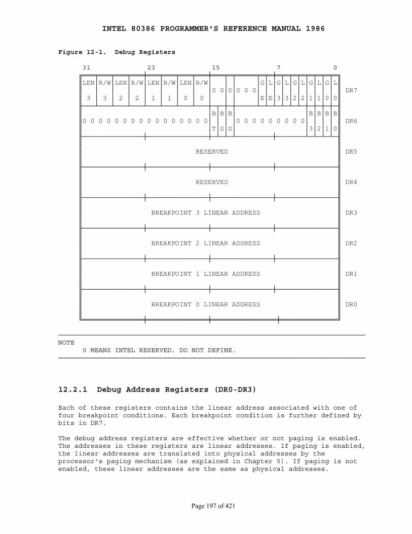
INTEL 80386 PROGRAMMER'S REFERENCE MANUAL 1986
Page 197 of 421
Figure 12-1. Debug Registers
31 23 15 7 0 ╔═══╤═══╤═══╤═══╪═══╤═══╤═══╤═══╪═══╤═╤═════╤═╤═╪═╤═╤═╤═╤═╤═╤═╤═╗ ║LEN│R/W│LEN│R/W│LEN│R/W│LEN│R/W│ │ │ │G│L│G│L│G│L│G│L│G│L║ ║ │ │ │ │ │ │ │ │0 0│0│0 0 0│ │ │ │ │ │ │ │ │ │ ║ DR7 ║ 3 │ 3 │ 2 │ 2 │ 1 │ 1 │ 0 │ 0 │ │ │ │E│E│3│3│2│2│1│1│0│0║ ╟───┴───┴───┴───┴───┴───┴───┴───┼─┬─┼─┼─────┴─┴─┴─┴─┴─┴─┼─┼─┼─┼─╢ ║ │B│B│B│ │B│B│B│B║ ║0 0 0 0 0 0 0 0 0 0 0 0 0 0 0 0│ │ │ │0 0 0 0 0 0 0 0 0│ │ │ │ ║ DR6 ║ │T│S│D│ │3│2│1│0║ ╟───────────────┼───────────────┼─┴─┴─┴─────────┼───────┴─┴─┴─┴─╢ ║ ║ ║ RESERVED ║ DR5 ║ ║ ╟───────────────┼───────────────┼───────────────┼───────────────╢ ║ ║ ║ RESERVED ║ DR4 ║ ║ ╟───────────────┼───────────────┼───────────────┼───────────────╢ ║ ║ ║ BREAKPOINT 3 LINEAR ADDRESS ║ DR3 ║ ║ ╟───────────────┼───────────────┼───────────────┼───────────────╢ ║ ║ ║ BREAKPOINT 2 LINEAR ADDRESS ║ DR2 ║ ║ ╟───────────────┼───────────────┼───────────────┼───────────────╢ ║ ║ ║ BREAKPOINT 1 LINEAR ADDRESS ║ DR1 ║ ║ ╟───────────────┼───────────────┼───────────────┼───────────────╢ ║ ║ ║ BREAKPOINT 0 LINEAR ADDRESS ║ DR0 ║ ║ ╚═══════════════╪═══════════════╪════════════════╪══════════════╝
────────────────────────────────────────────────────────────────────────────NOTE 0 MEANS INTEL RESERVED. DO NOT DEFINE.────────────────────────────────────────────────────────────────────────────
12.2.1 Debug Address Registers (DR0-DR3)
Each of these registers contains the linear address associated with one offour breakpoint conditions. Each breakpoint condition is further defined bybits in DR7.
The debug address registers are effective whether or not paging is enabled.The addresses in these registers are linear addresses. If paging is enabled,the linear addresses are translated into physical addresses by theprocessor's paging mechanism (as explained in Chapter 5). If paging is notenabled, these linear addresses are the same as physical addresses.
INTEL 80386 PROGRAMMER'S REFERENCE MANUAL 1986
Page 198 of 421
Note that when paging is enabled, different tasks may have differentlinear-to-physical address mappings. When this is the case, an address in adebug address register may be relevant to one task but not to another. Forthis reason the 80386 has both global and local enable bits in DR7. Thesebits indicate whether a given debug address has a global (all tasks) orlocal (current task only) relevance.
12.2.2 Debug Control Register (DR7)
The debug control register shown in Figure 12-1 both helps to define thedebug conditions and selectively enables and disables those conditions.
For each address in registers DR0-DR3, the corresponding fields R/W0through R/W3 specify the type of action that should cause a breakpoint. Theprocessor interprets these bits as follows:
00 ── Break on instruction execution only 01 ── Break on data writes only 10 ── undefined 11 ── Break on data reads or writes but not instruction fetches
Fields LEN0 through LEN3 specify the length of data item to be monitored. Alength of 1, 2, or 4 bytes may be specified. The values of the length fieldsare interpreted as follows:
00 ── one-byte length 01 ── two-byte length 10 ── undefined 11 ── four-byte length
If RWn is 00 (instruction execution), then LENn should also be 00. Any otherlength is undefined.
The low-order eight bits of DR7 (L0 through L3 and G0 through G3)selectively enable the four address breakpoint conditions. There are twolevels of enabling: the local (L0 through L3) and global (G0 through G3)levels. The local enable bits are automatically reset by the processor atevery task switch to avoid unwanted breakpoint conditions in the new task.The global enable bits are not reset by a task switch; therefore, they canbe used for conditions that are global to all tasks.
The LE and GE bits control the "exact data breakpoint match" feature of theprocessor. If either LE or GE is set, the processor slows execution so thatdata breakpoints are reported on the instruction that causes them. It isrecommended that one of these bits be set whenever data breakpoints arearmed. The processor clears LE at a task switch but does not clear GE.
12.2.3 Debug Status Register (DR6)
The debug status register shown in Figure 12-1 permits the debugger todetermine which debug conditions have occurred.
INTEL 80386 PROGRAMMER'S REFERENCE MANUAL 1986
Page 199 of 421
When the processor detects an enabled debug exception, it sets thelow-order bits of this register (B0 thru B3) before entering the debugexception handler. Bn is set if the condition described by DRn, LENn, andR/Wn occurs. (Note that the processor sets Bn regardless of whether Gn orLn is set. If more than one breakpoint condition occurs at one time and ifthe breakpoint trap occurs due to an enabled condition other than n, Bn maybe set, even though neither Gn nor Ln is set.)
The BT bit is associated with the T-bit (debug trap bit) of the TSS (referto 7 for the location of the T-bit). The processor sets the BT bit beforeentering the debug handler if a task switch has occurred and the T-bit ofthe new TSS is set. There is no corresponding bit in DR7 that enables anddisables this trap; the T-bit of the TSS is the sole enabling bit.
The BS bit is associated with the TF (trap flag) bit of the EFLAGSregister. The BS bit is set if the debug handler is entered due to theoccurrence of a single-step exception. The single-step trap is thehighest-priority debug exception; therefore, when BS is set, any of theother debug status bits may also be set.
The BD bit is set if the next instruction will read or write one of theeight debug registers and ICE-386 is also using the debug registers at thesame time.
Note that the bits of DR6 are never cleared by the processor. To avoid anyconfusion in identifying the next debug exception, the debug handler shouldmove zeros to DR6 immediately before returning.
12.2.4 Breakpoint Field Recognition
The linear address and LEN field for each of the four breakpoint conditionsdefine a range of sequential byte addresses for a data breakpoint. The LENfield permits specification of a one-, two-, or four-byte field. Two-bytefields must be aligned on word boundaries (addresses that are multiples oftwo) and four-byte fields must be aligned on doubleword boundaries(addresses that are multiples of four). These requirements are enforced bythe processor; it uses the LEN bits to mask the low-order bits of theaddresses in the debug address registers. Improperly aligned code or databreakpoint addresses will not yield the expected results.
A data read or write breakpoint is triggered if any of the bytesparticipating in a memory access is within the field defined by a breakpointaddress register and the corresponding LEN field. Table 12-1 gives someexamples of breakpoint fields with memory references that both do and do notcause traps.
To set a data breakpoint for a misaligned field longer than one byte, itmay be desirable to put two sets of entries in the breakpoint register suchthat each entry is properly aligned and the two entries together span thelength of the field.
Instruction breakpoint addresses must have a length specification of onebyte (LEN = 00); other values are undefined. The processor recognizes aninstruction breakpoint address only when it points to the first byte of an

INTEL 80386 PROGRAMMER'S REFERENCE MANUAL 1986
Page 200 of 421
instruction. If the instruction has any prefixes, the breakpoint addressmust point to the first prefix.
Table 12-1. Breakpoint Field Recognition Examples
Address (hex) Length
DR0 0A0001 1 (LEN0 = 00)Register Contents DR1 0A0002 1 (LEN1 = 00) DR2 0B0002 2 (LEN2 = 01) DR3 0C0000 4 (LEN3 = 11)
Some Examples of Memory 0A0001 1References That Cause Traps 0A0002 1 0A0001 2 0A0002 2 0B0002 2 0B0001 4 0C0000 4 0C0001 2 0C0003 1
Some Examples of Memory 0A0000 1References That Don't Cause Traps 0A0003 4 0B0000 2 0C0004 4
12.3 Debug Exceptions
Two of the interrupt vectors of the 80386 are reserved for exceptions thatrelate to debugging. Interrupt 1 is the primary means of invoking debuggersdesigned expressly for the 80386; interrupt 3 is intended for debuggingdebuggers and for compatibility with prior processors in Intel's 8086processor family.
12.3.1 Interrupt 1 ── Debug ExceptionsThe handler for this exception is usually a debugger or part of a debuggingsystem. The processor causes interrupt 1 for any of several conditions. Thedebugger can check flags in DR6 and DR7 to determine what condition causedthe exception and what other conditions might be in effect at the same time.Table 12-2 associates with each breakpoint condition the combination ofbits that indicate when that condition has caused the debug exception.
Instruction address breakpoint conditions are faults, while other debugconditions are traps. The debug exception may report either or both at onetime. The following paragraphs present details for each class of debugexception.
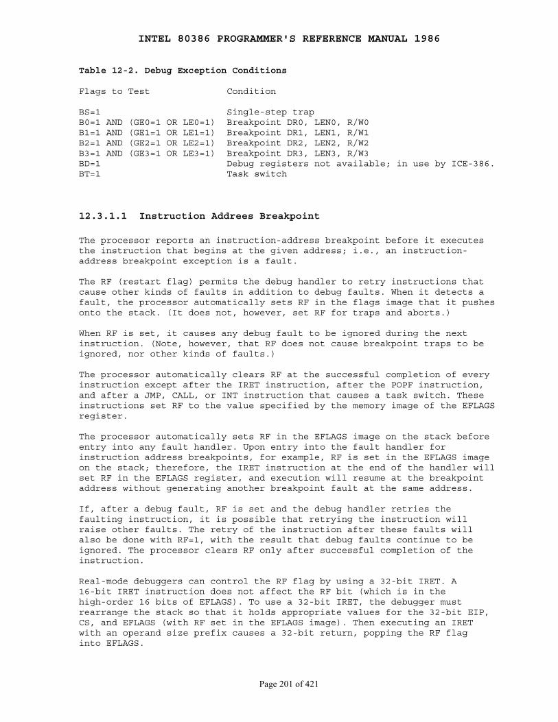
INTEL 80386 PROGRAMMER'S REFERENCE MANUAL 1986
Page 201 of 421
Table 12-2. Debug Exception Conditions
Flags to Test Condition
BS=1 Single-step trapB0=1 AND (GE0=1 OR LE0=1) Breakpoint DR0, LEN0, R/W0B1=1 AND (GE1=1 OR LE1=1) Breakpoint DR1, LEN1, R/W1B2=1 AND (GE2=1 OR LE2=1) Breakpoint DR2, LEN2, R/W2B3=1 AND (GE3=1 OR LE3=1) Breakpoint DR3, LEN3, R/W3BD=1 Debug registers not available; in use by ICE-386.BT=1 Task switch
12.3.1.1 Instruction Addrees Breakpoint
The processor reports an instruction-address breakpoint before it executesthe instruction that begins at the given address; i.e., an instruction-address breakpoint exception is a fault.
The RF (restart flag) permits the debug handler to retry instructions thatcause other kinds of faults in addition to debug faults. When it detects afault, the processor automatically sets RF in the flags image that it pushesonto the stack. (It does not, however, set RF for traps and aborts.)
When RF is set, it causes any debug fault to be ignored during the nextinstruction. (Note, however, that RF does not cause breakpoint traps to beignored, nor other kinds of faults.)
The processor automatically clears RF at the successful completion of everyinstruction except after the IRET instruction, after the POPF instruction,and after a JMP, CALL, or INT instruction that causes a task switch. Theseinstructions set RF to the value specified by the memory image of the EFLAGSregister.
The processor automatically sets RF in the EFLAGS image on the stack beforeentry into any fault handler. Upon entry into the fault handler forinstruction address breakpoints, for example, RF is set in the EFLAGS imageon the stack; therefore, the IRET instruction at the end of the handler willset RF in the EFLAGS register, and execution will resume at the breakpointaddress without generating another breakpoint fault at the same address.
If, after a debug fault, RF is set and the debug handler retries thefaulting instruction, it is possible that retrying the instruction willraise other faults. The retry of the instruction after these faults willalso be done with RF=1, with the result that debug faults continue to beignored. The processor clears RF only after successful completion of theinstruction.
Real-mode debuggers can control the RF flag by using a 32-bit IRET. A16-bit IRET instruction does not affect the RF bit (which is in thehigh-order 16 bits of EFLAGS). To use a 32-bit IRET, the debugger mustrearrange the stack so that it holds appropriate values for the 32-bit EIP,CS, and EFLAGS (with RF set in the EFLAGS image). Then executing an IRETwith an operand size prefix causes a 32-bit return, popping the RF flaginto EFLAGS.
INTEL 80386 PROGRAMMER'S REFERENCE MANUAL 1986
Page 202 of 421
12.3.1.2 Data Address Breakpoint
A data-address breakpoint exception is a trap; i.e., the processor reportsa data-address breakpoint after executing the instruction that accesses thegiven memory item.
When using data breakpoints it is recommended that either the LE or GE bitof DR7 be set also. If either LE or GE is set, any data breakpoint trap isreported exactly after completion of the instruction that accessed thespecified memory item. This exact reporting is accomplished by forcing the80386 execution unit to wait for completion of data operand transfers beforebeginning execution of the next instruction. If neither GE nor LE is set,data breakpoints may not be reported until one instruction after the data isaccessed or may not be reported at all. This is due to the fact that,normally, instruction execution is overlapped with memory transfers to sucha degree that execution of the next instruction may begin before memorytransfers for the prior instruction are completed.
If a debugger needs to preserve the contents of a write breakpointlocation, it should save the original contents before setting a writebreakpoint. Because data breakpoints are traps, a write into a breakpointlocation will complete before the trap condition is reported. The handlercan report the saved value after the breakpoint is triggered. The data inthe debug registers can be used to address the new value stored by theinstruction that triggered the breakpoint.
12.3.1.3 General Detect Fault
This exception occurs when an attempt is made to use the debug registers atthe same time that ICE-386 is using them. This additional protection featureis provided to guarantee that ICE-386 can have full control over thedebug-register resources when required. ICE-386 uses the debug-registers;therefore, a software debugger that also uses these registers cannot runwhile ICE-386 is in use. The exception handler can detect this condition byexamining the BD bit of DR6.
12.3.1.4 Single-Step Trap
This debug condition occurs at the end of an instruction if the trap flag(TF) of the flags register held the value one at the beginning of thatinstruction. Note that the exception does not occur at the end of aninstruction that sets TF. For example, if POPF is used to set TF, asingle-step trap does not occur until after the instruction that followsPOPF.
The processor clears the TF bit before invoking the handler. If TF=1 inthe flags image of a TSS at the time of a task switch, the exception occursafter the first instruction is executed in the new task.
The single-step flag is normally not cleared by privilege changes inside atask. INT instructions, however, do clear TF. Therefore, software
INTEL 80386 PROGRAMMER'S REFERENCE MANUAL 1986
Page 203 of 421
debuggers that single-step code must recognize and emulate INT n or INTOrather than executing them directly.
To maintain protection, system software should check the current executionprivilege level after any single step interrupt to see whether singlestepping should continue at the current privilege level.
The interrupt priorities in hardware guarantee that if an externalinterrupt occurs, single stepping stops. When both an external interrupt anda single step interrupt occur together, the single step interrupt isprocessed first. This clears the TF bit. After saving the return address orswitching tasks, the external interrupt input is examined before the firstinstruction of the single step handler executes. If the external interruptis still pending, it is then serviced. The external interrupt handler is notsingle-stepped. To single step an interrupt handler, just single step an INTn instruction that refers to the interrupt handler.
12.3.1.5 Task Switch Breakpoint
The debug exception also occurs after a switch to an 80386 task if theT-bit of the new TSS is set. The exception occurs after control has passedto the new task, but before the first instruction of that task is executed.The exception handler can detect this condition by examining the BT bit ofthe debug status register DR6.
Note that if the debug exception handler is a task, the T-bit of its TSSshould not be set. Failure to observe this rule will cause the processor toenter an infinite loop.
12.3.2 Interrupt 3 ── Breakpoint ExceptionThis exception is caused by execution of the breakpoint instruction INT 3.Typically, a debugger prepares a breakpoint by substituting the opcode ofthe one-byte breakpoint instruction in place of the first opcode byte of theinstruction to be trapped. When execution of the INT 3 instruction causesthe exception handler to be invoked, the saved value of ES:EIP points to thebyte following the INT 3 instruction.
With prior generations of processors, this feature is used extensively fortrapping execution of specific instructions. With the 80386, the needsformerly filled by this feature are more conveniently solved via the debugregisters and interrupt 1. However, the breakpoint exception is stilluseful for debugging debuggers, because the breakpoint exception can vectorto a different exception handler than that used by the debugger. Thebreakpoint exception can also be useful when it is necessary to set agreater number of breakpoints than permitted by the debug registers.
INTEL 80386 PROGRAMMER'S REFERENCE MANUAL 1986
Page 204 of 421
PART III COMPATIBILITY
Chapter 13 Executing 80286 Protected-Mode Code
────────────────────────────────────────────────────────────────────────────
13.1 80286 Code Executes as a Subset of the 80386
In general, programs designed for execution in protected mode on an 80286execute without modification on the 80386, because the features of the 80286are a subset of those of the 80386.
All the descriptors used by the 80286 are supported by the 80386 as long asthe Intel-reserved word (last word) of the 80286 descriptor is zero.
The descriptors for data segments, executable segments, local descriptortables, and task gates are common to both the 80286 and the 80386. Other80286 descriptors──TSS segment, call gate, interrupt gate, and trapgate──are supported by the 80386. The 80386 also has new versions ofdescriptors for TSS segment, call gate, interrupt gate, and trap gate thatsupport the 32-bit nature of the 80386. Both sets of descriptors can beused simultaneously in the same system.
For those descriptors that are common to both the 80286 and the 80386, thepresence of zeros in the final word causes the 80386 to interpret thesedescriptors exactly as 80286 does; for example:
Base Address The high-order eight bits of the 32-bit base address are zero, limiting base addresses to 24 bits.
Limit The high-order four bits of the limit field are zero, restricting the value of the limit field to 64K.
Granularity bit The granularity bit is zero, which implies that the value of the 16-bit limit is interpreted in units of one byte.
B-bit In a data-segment descriptor, the B-bit is zero, implying that the segment is no larger than 64 Kbytes.
D-bit In an executable-segment descriptor, the D-bit is zero, implying that 16-bit addressing and operands are the default.
For formats of these descriptors and documentation of their use refer tothe iAPX 286 Programmer's Reference Manual.
INTEL 80386 PROGRAMMER'S REFERENCE MANUAL 1986
Page 205 of 421
13.2 Two ways to Execute 80286 Tasks
When porting 80286 programs to the 80386, there are two cases to consider:
1. Porting an entire 80286 system to the 80386, complete with 80286 operating system, loader, and system builder.
In this case, all tasks will have 80286 TSSs. The 80386 is being used as a faster 286.
2. Porting selected 80286 applications to run in an 80386 environment with an 80386 operating system, loader, and system builder.
In this case, the TSSs used to represent 80286 tasks should be changed to 80386 TSSs. It is theoretically possible to mix 80286 and 80386 TSSs, but the benefits are slight and the problems are great. It is recommended that all tasks in a 80386 software system have 80386 TSSs. It is not necessary to change the 80286 object modules themselves; TSSs are usually constructed by the operating system, by the loader, or by the system builder. Refer to Chapter 16 for further discussion of the interface between 16-bit and 32-bit code.
13.3 Differences From 80286
The few differences that do exist primarily affect operating system code.
13.3.1 Wraparound of 80286 24-Bit Physical Address Space
With the 80286, any base and offset combination that addresses beyond 16Mbytes wraps around to the first megabyte of the 80286 address space. Withthe 80386, since it has a greater physical address space, any such addressfalls into the 17th megabyte. In the unlikely event that any softwaredepends on this anomaly, the same effect can be simulated on the 80386 byusing paging to map the first 64K bytes of the 17th megabyte of logicaladdresses to physical addresses in the first megabyte.
13.3.2 Reserved Word of Descriptor
Because the 80386 uses the contents of the reserved word (last word) ofevery descriptor, 80286 programs that place values in this word may notexecute correctly on the 80386.

INTEL 80386 PROGRAMMER'S REFERENCE MANUAL 1986
Page 206 of 421
13.3.3 New Descriptor Type Codes
Operating-system code that manages space in descriptor tables often uses aninvalid value in the access-rights field of descriptor-table entries toidentify unused entries. Access rights values of 80H and 00H remain invalidfor both the 80286 and 80386. Other values that were invalid on for the80286 may be valid for the 80386 because of the additional descriptor typesdefined by the 80386.
13.3.4 Restricted Semantics of LOCK
The 80286 processor implements the bus lock function differently than the80386. Programs that use forms of memory locking specific to the 80286 maynot execute properly when transported to a specific application of the80386.
The LOCK prefix and its corresponding output signal should only be used toprevent other bus masters from interrupting a data movement operation. LOCKmay only be used with the following 80386 instructions when they modifymemory. An undefined-opcode exception results from using LOCK before anyother instruction.
● Bit test and change: BTS, BTR, BTC. ● Exchange: XCHG. ● One-operand arithmetic and logical: INC, DEC, NOT, and NEG. ● Two-operand arithmetic and logical: ADD, ADC, SUB, SBB, AND, OR, XOR.
A locked instruction is guaranteed to lock only the area of memory definedby the destination operand, but may lock a larger memory area. For example,typical 8086 and 80286 configurations lock the entire physical memory space.With the 80386, the defined area of memory is guaranteed to be lockedagainst access by a processor executing a locked instruction on exactly thesame memory area, i.e., an operand with identical starting address andidentical length.
13.3.5 Additional Exceptions
The 80386 defines new exceptions that can occur even in systems designedfor the 80286.
● Exception #6 ── invalid opcode
This exception can result from improper use of the LOCK instruction.
● Exception #14 ── page fault
This exception may occur in an 80286 program if the operating system enables paging. Paging can be used in a system with 80286 tasks as long as all tasks use the same page directory. Because there is no place in an 80286 TSS to store the PDBR, switching to an 80286 task does not change the value of PDBR. Tasks ported from the 80286 should be given 80386 TSSs so they can take full advantage of paging.
INTEL 80386 PROGRAMMER'S REFERENCE MANUAL 1986
Page 207 of 421
Chapter 14 80386 Real-Address Mode
────────────────────────────────────────────────────────────────────────────
The real-address mode of the 80386 executes object code designed forexecution on 8086, 8088, 80186, or 80188 processors, or for execution in thereal-address mode of an 80286:
In effect, the architecture of the 80386 in this mode is almost identicalto that of the 8086, 8088, 80186, and 80188. To a programmer, an 80386 inreal-address mode appears as a high-speed 8086 with extensions to theinstruction set and registers. The principal features of this architectureare defined in Chapters 2 and 3.
This chapter discusses certain additional topics that complete the systemprogrammer's view of the 80386 in real-address mode:
● Address formation. ● Extensions to registers and instructions. ● Interrupt and exception handling. ● Entering and leaving real-address mode. ● Real-address-mode exceptions. ● Differences from 8086. ● Differences from 80286 real-address mode.
14.1 Physical Address Formation
The 80386 provides a one Mbyte + 64 Kbyte memory space for an 8086 program.Segment relocation is performed as in the 8086: the 16-bit value in asegment selector is shifted left by four bits to form the base address of asegment. The effective address is extended with four high order zeros andadded to the base to form a linear address as Figure 14-1 illustrates. (Thelinear address is equivalent to the physical address, because paging is notused in real-address mode.) Unlike the 8086, the resulting linear addressmay have up to 21 significant bits. There is a possibility of a carry whenthe base address is added to the effective address. On the 8086, the carriedbit is truncated, whereas on the 80386 the carried bit is stored in bitposition 20 of the linear address.
Unlike the 8086 and 80286, 32-bit effective addresses can be generated (viathe address-size prefix); however, the value of a 32-bit address may notexceed 65535 without causing an exception. For full compatibility with 80286real-address mode, pseudo-protection faults (interrupt 12 or 13 with noerror code) occur if an effective address is generated outside the range 0through 65535.
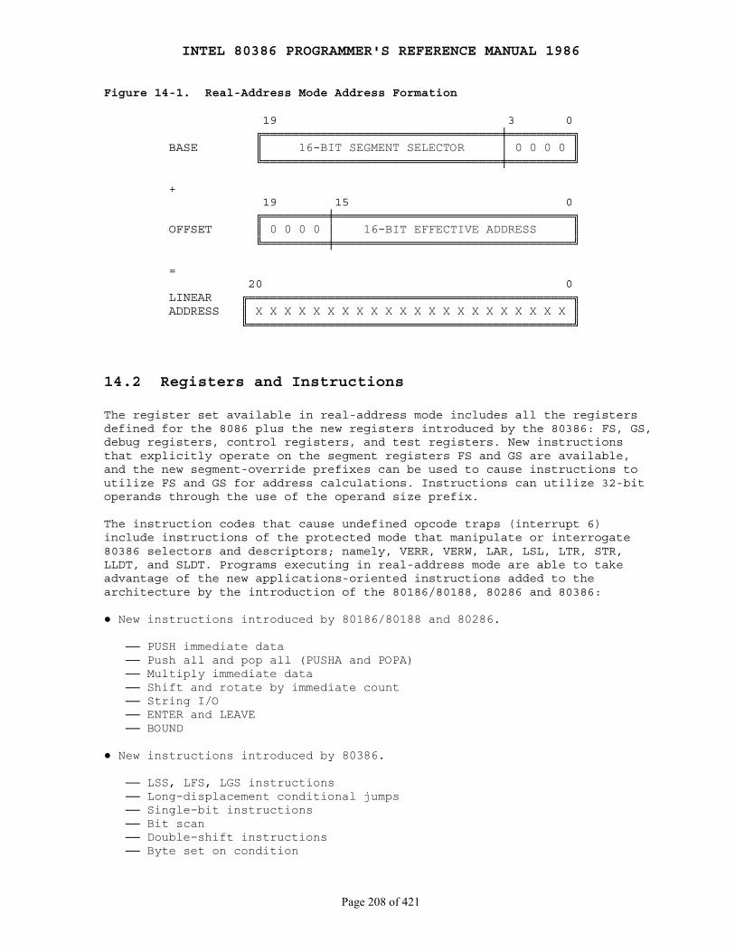
INTEL 80386 PROGRAMMER'S REFERENCE MANUAL 1986
Page 208 of 421
Figure 14-1. Real-Address Mode Address Formation
19 3 0 ╔═════════════════════════════════╪═════════╗ BASE ║ 16-BIT SEGMENT SELECTOR │ 0 0 0 0 ║ ╚═════════════════════════════════╪═════════╝
+ 19 15 0 ╔═════════╪═════════════════════════════════╗ OFFSET ║ 0 0 0 0 │ 16-BIT EFFECTIVE ADDRESS ║ ╚═════════╪═════════════════════════════════╝
= 20 0 LINEAR ╔═════════════════════════════════════════════╗ ADDRESS ║ X X X X X X X X X X X X X X X X X X X X X X ║ ╚═════════════════════════════════════════════╝
14.2 Registers and Instructions
The register set available in real-address mode includes all the registersdefined for the 8086 plus the new registers introduced by the 80386: FS, GS,debug registers, control registers, and test registers. New instructionsthat explicitly operate on the segment registers FS and GS are available,and the new segment-override prefixes can be used to cause instructions toutilize FS and GS for address calculations. Instructions can utilize 32-bitoperands through the use of the operand size prefix.
The instruction codes that cause undefined opcode traps (interrupt 6)include instructions of the protected mode that manipulate or interrogate80386 selectors and descriptors; namely, VERR, VERW, LAR, LSL, LTR, STR,LLDT, and SLDT. Programs executing in real-address mode are able to takeadvantage of the new applications-oriented instructions added to thearchitecture by the introduction of the 80186/80188, 80286 and 80386:
● New instructions introduced by 80186/80188 and 80286.
── PUSH immediate data ── Push all and pop all (PUSHA and POPA) ── Multiply immediate data ── Shift and rotate by immediate count ── String I/O ── ENTER and LEAVE ── BOUND
● New instructions introduced by 80386.
── LSS, LFS, LGS instructions ── Long-displacement conditional jumps ── Single-bit instructions ── Bit scan ── Double-shift instructions ── Byte set on condition
INTEL 80386 PROGRAMMER'S REFERENCE MANUAL 1986
Page 209 of 421
── Move with sign/zero extension ── Generalized multiply ── MOV to and from control registers ── MOV to and from test registers ── MOV to and from debug registers
14.3 Interrupt and Exception Handling
Interrupts and exceptions in 80386 real-address mode work as much as theydo on an 8086. Interrupts and exceptions vector to interrupt procedures viaan interrupt table. The processor multiplies the interrupt or exceptionidentifier by four to obtain an index into the interrupt table. The entriesof the interrupt table are far pointers to the entry points of interrupt orexception handler procedures. When an interrupt occurs, the processorpushes the current values of CS:IP onto the stack, disables interrupts,clears TF (the single-step flag), then transfers control to the locationspecified in the interrupt table. An IRET instruction at the end of thehandler procedure reverses these steps before returning control to theinterrupted procedure.
The primary difference in the interrupt handling of the 80386 compared tothe 8086 is that the location and size of the interrupt table depend on thecontents of the IDTR (IDT register). Ordinarily, this fact is not apparentto programmers, because, after RESET, the IDTR contains a base address of 0and a limit of 3FFH, which is compatible with the 8086. However, the LIDTinstruction can be used in real-address mode to change the base and limitvalues in the IDTR. Refer to Chapter 9 for details on the IDTR, and theLIDT and SIDT instructions. If an interrupt occurs and the correspondingentry of the interrupt table is beyond the limit stored in the IDTR, theprocessor raises exception 8.
14.4 Entering and Leaving Real-Address Mode
Real-address mode is in effect after a signal on the RESET pin. Even if thesystem is going to be used in protected mode, the start-up program willexecute in real-address mode temporarily while initializing for protectedmode.
14.4.1 Switching to Protected Mode
The only way to leave real-address mode is to switch to protected mode. Theprocessor enters protected mode when a MOV to CR0 instruction sets the PE(protection enable) bit in CR0. (For compatibility with the 80286, the LMSWinstruction may also be used to set the PE bit.)
Refer to Chapter 10 "Initialization" for other aspects of switching toprotected mode.
INTEL 80386 PROGRAMMER'S REFERENCE MANUAL 1986
Page 210 of 421
14.5 Switching Back to Real-Address Mode
The processor reenters real-address mode if software clears the PE bit inCR0 with a MOV to CR0 instruction. A procedure that attempts to do this,however, should proceed as follows:
1. If paging is enabled, perform the following sequence:
● Transfer control to linear addresses that have an identity mapping; i.e., linear addresses equal physical addresses.
● Clear the PG bit in CR0.
● Move zeros to CR3 to clear out the paging cache.
2. Transfer control to a segment that has a limit of 64K (FFFFH). This loads the CS register with the limit it needs to have in real mode.
3. Load segment registers SS, DS, ES, FS, and GS with a selector that points to a descriptor containing the following values, which are appropriate to real mode:
● Limit = 64K (FFFFH) ● Byte granular (G = 0) ● Expand up (E = 0) ● Writable (W = 1) ● Present (P = 1) ● Base = any value
4. Disable interrupts. A CLI instruction disables INTR interrupts. NMIs can be disabled with external circuitry.
5. Clear the PE bit.
6. Jump to the real mode code to be executed using a far JMP. This action flushes the instruction queue and puts appropriate values in the access rights of the CS register.
7. Use the LIDT instruction to load the base and limit of the real-mode interrupt vector table.
8. Enable interrupts.
9. Load the segment registers as needed by the real-mode code.
14.6 Real-Address Mode Exceptions
The 80386 reports some exceptions differently when executing inreal-address mode than when executing in protected mode. Table 14-1 detailsthe real-address-mode exceptions.
INTEL 80386 PROGRAMMER'S REFERENCE MANUAL 1986
Page 211 of 421
14.7 Differences From 8086
In general, the 80386 in real-address mode will correctly execute ROM-basedsoftware designed for the 8086, 8088, 80186, and 80188. Following is a listof the minor differences between 8086 execution on the 80386 and on an 8086.
1. Instruction clock counts.
The 80386 takes fewer clocks for most instructions than the 8086/8088. The areas most likely to be affected are:
● Delays required by I/O devices between I/O operations.
● Assumed delays with 8086/8088 operating in parallel with an 8087.
2. Divide Exceptions Point to the DIV instruction.
Divide exceptions on the 80386 always leave the saved CS:IP value pointing to the instruction that failed. On the 8086/8088, the CS:IP value points to the next instruction.
3. Undefined 8086/8088 opcodes.
Opcodes that were not defined for the 8086/8088 will cause exception 6 or will execute one of the new instructions defined for the 80386.
4. Value written by PUSH SP.
The 80386 pushes a different value on the stack for PUSH SP than the 8086/8088. The 80386 pushes the value of SP before SP is incremented as part of the push operation; the 8086/8088 pushes the value of SP after it is incremented. If the value pushed is important, replace PUSH SP instructions with the following three instructions:
PUSH BP MOV BP, SP XCHG BP, [BP]
This code functions as the 8086/8088 PUSH SP instruction on the 80386.
5. Shift or rotate by more than 31 bits.
The 80386 masks all shift and rotate counts to the low-order five bits. This MOD 32 operation limits the count to a maximum of 31 bits, thereby limiting the time that interrupt response is delayed while the instruction is executing.
6. Redundant prefixes.
The 80386 sets a limit of 15 bytes on instruction length. The only way to violate this limit is by putting redundant prefixes before an instruction. Exception 13 occurs if the limit on instruction length is violated. The 8086/8088 has no instruction length limit.
INTEL 80386 PROGRAMMER'S REFERENCE MANUAL 1986
Page 212 of 421
7. Operand crossing offset 0 or 65,535.
On the 8086, an attempt to access a memory operand that crosses offset 65,535 (e.g., MOV a word to offset 65,535) or offset 0 (e.g., PUSH a word when SP = 1) causes the offset to wrap around modulo 65,536. The 80386 raises an exception in these cases──exception 13 if the segment is a data segment (i.e., if CS, DS, ES, FS, or GS is being used to address the segment), exception 12 if the segment is a stack segment (i.e., if SS is being used).
8. Sequential execution across offset 65,535.
On the 8086, if sequential execution of instructions proceeds past offset 65,535, the processor fetches the next instruction byte from offset 0 of the same segment. On the 80386, the processor raises exception 13 in such a case.
9. LOCK is restricted to certain instructions.
The LOCK prefix and its corresponding output signal should only be used to prevent other bus masters from interrupting a data movement operation. The 80386 always asserts the LOCK signal during an XCHG instruction with memory (even if the LOCK prefix is not used). LOCK may only be used with the following 80386 instructions when they update memory: BTS, BTR, BTC, XCHG, ADD, ADC, SUB, SBB, INC, DEC, AND, OR, XOR, NOT, and NEG. An undefined-opcode exception (interrupt 6) results from using LOCK before any other instruction.
10. Single-stepping external interrupt handlers.
The priority of the 80386 single-step exception is different from that of the 8086/8088. The change prevents an external interrupt handler from being single-stepped if the interrupt occurs while a program is being single-stepped. The 80386 single-step exception has higher priority that any external interrupt. The 80386 will still single-step through an interrupt handler invoked by the INT instructions or by an exception.
11. IDIV exceptions for quotients of 80H or 8000H.
The 80386 can generate the largest negative number as a quotient for the IDIV instruction. The 8086/8088 causes exception zero instead.
12. Flags in stack.
The setting of the flags stored by PUSHF, by interrupts, and by exceptions is different from that stored by the 8086 in bit positions 12 through 15. On the 8086 these bits are stored as ones, but in 80386 real-address mode bit 15 is always zero, and bits 14 through 12 reflect the last value loaded into them.
13. NMI interrupting NMI handlers.
After an NMI is recognized on the 80386, the NMI interrupt is masked until an IRET instruction is executed.
INTEL 80386 PROGRAMMER'S REFERENCE MANUAL 1986
Page 213 of 421
14. Coprocessor errors vector to interrupt 16.
Any 80386 system with a coprocessor must use interrupt vector 16 for the coprocessor error exception. If an 8086/8088 system uses another vector for the 8087 interrupt, both vectors should point to the coprocessor-error exception handler.
15. Numeric exception handlers should allow prefixes.
On the 80386, the value of CS:IP saved for coprocessor exceptions points at any prefixes before an ESC instruction. On 8086/8088 systems, the saved CS:IP points to the ESC instruction.
16. Coprocessor does not use interrupt controller.
The coprocessor error signal to the 80386 does not pass through an interrupt controller (an 8087 INT signal does). Some instructions in a coprocessor error handler may need to be deleted if they deal with the interrupt controller.
17. Six new interrupt vectors.
The 80386 adds six exceptions that arise only if the 8086 program has a hidden bug. It is recommended that exception handlers be added that treat these exceptions as invalid operations. This additional software does not significantly affect the existing 8086 software because the interrupts do not normally occur. These interrupt identifiers should not already have been used by the 8086 software, because they are in the range reserved by Intel. Table 14-2 describes the new 80386 exceptions.
18. One megabyte wraparound.
The 80386 does not wrap addresses at 1 megabyte in real-address mode. On members of the 8086 family, it possible to specify addresses greater than one megabyte. For example, with a selector value 0FFFFH and an offset of 0FFFFH, the effective address would be 10FFEFH (1 Mbyte + 65519). The 8086, which can form adresses only up to 20 bits long, truncates the high-order bit, thereby "wrapping" this address to 0FFEFH. However, the 80386, which can form addresses up to 32 bits long does not truncate such an address.
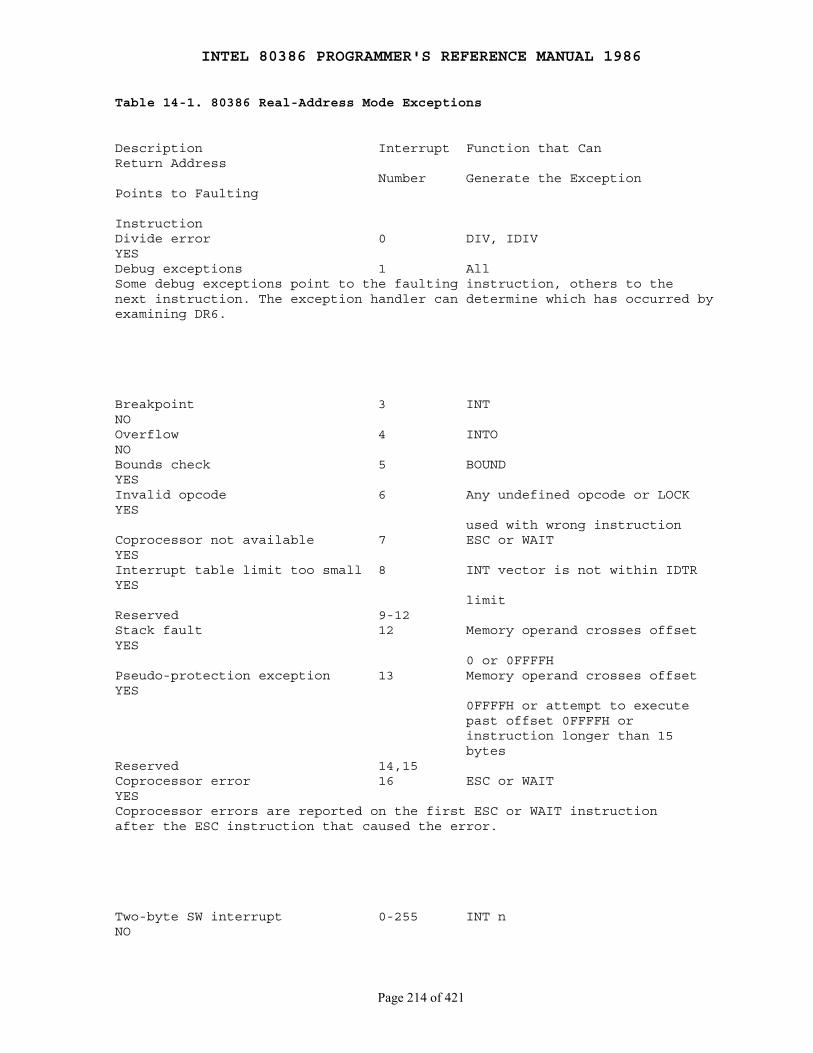
INTEL 80386 PROGRAMMER'S REFERENCE MANUAL 1986
Page 214 of 421
Table 14-1. 80386 Real-Address Mode Exceptions
Description Interrupt Function that CanReturn Address Number Generate the ExceptionPoints to Faulting
InstructionDivide error 0 DIV, IDIVYESDebug exceptions 1 AllSome debug exceptions point to the faulting instruction, others to thenext instruction. The exception handler can determine which has occurred byexamining DR6.
Breakpoint 3 INTNOOverflow 4 INTONOBounds check 5 BOUNDYESInvalid opcode 6 Any undefined opcode or LOCKYES used with wrong instructionCoprocessor not available 7 ESC or WAITYESInterrupt table limit too small 8 INT vector is not within IDTRYES limitReserved 9-12Stack fault 12 Memory operand crosses offsetYES 0 or 0FFFFHPseudo-protection exception 13 Memory operand crosses offsetYES 0FFFFH or attempt to execute past offset 0FFFFH or instruction longer than 15 bytesReserved 14,15Coprocessor error 16 ESC or WAITYESCoprocessor errors are reported on the first ESC or WAIT instructionafter the ESC instruction that caused the error.
Two-byte SW interrupt 0-255 INT nNO
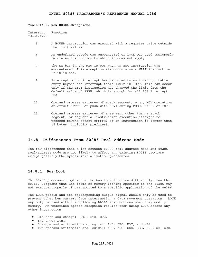
INTEL 80386 PROGRAMMER'S REFERENCE MANUAL 1986
Page 215 of 421
Table 14-2. New 80386 Exceptions
Interrupt FunctionIdentifier
5 A BOUND instruction was executed with a register value outside the limit values.
6 An undefined opcode was encountered or LOCK was used improperly before an instruction to which it does not apply.
7 The EM bit in the MSW is set when an ESC instruction was encountered. This exception also occurs on a WAIT instruction if TS is set.
8 An exception or interrupt has vectored to an interrupt table entry beyond the interrupt table limit in IDTR. This can occur only if the LIDT instruction has changed the limit from the default value of 3FFH, which is enough for all 256 interrupt IDs.
12 Operand crosses extremes of stack segment, e.g., MOV operation at offset 0FFFFH or push with SP=1 during PUSH, CALL, or INT.
13 Operand crosses extremes of a segment other than a stack segment; or sequential instruction execution attempts to proceed beyond offset 0FFFFH; or an instruction is longer than 15 bytes (including prefixes).
14.8 Differences From 80286 Real-Address Mode
The few differences that exist between 80386 real-address mode and 80286real-address mode are not likely to affect any existing 80286 programsexcept possibly the system initialization procedures.
14.8.1 Bus Lock
The 80286 processor implements the bus lock function differently than the80386. Programs that use forms of memory locking specific to the 80286 maynot execute properly if transported to a specific application of the 80386.
The LOCK prefix and its corresponding output signal should only be used toprevent other bus masters from interrupting a data movement operation. LOCKmay only be used with the following 80386 instructions when they modifymemory. An undefined-opcode exception results from using LOCK before anyother instruction.
● Bit test and change: BTS, BTR, BTC. ● Exchange: XCHG. ● One-operand arithmetic and logical: INC, DEC, NOT, and NEG. ● Two-operand arithmetic and logical: ADD, ADC, SUB, SBB, AND, OR, XOR.

INTEL 80386 PROGRAMMER'S REFERENCE MANUAL 1986
Page 216 of 421
A locked instruction is guaranteed to lock only the area of memory definedby the destination operand, but may lock a larger memory area. For example,typical 8086 and 80286 configurations lock the entire physical memory space.With the 80386, the defined area of memory is guranteed to be locked againstaccess by a processor executing a locked instruction on exactly the samememory area, i.e., an operand with identical starting address and identicallength.
14.8.2 Location of First Instruction
The starting location is 0FFFFFFF0H (sixteen bytes from end of 32-bitaddress space) on the 80386 rather than 0FFFFF0H (sixteen bytes from end of24-bit address space) as on the 80286. Many 80286 ROM initializationprograms will work correctly in this new environment. Others can be made towork correctly with external hardware that redefines the signals onA{31-20}.
14.8.3 Initial Values of General Registers
On the 80386, certain general registers may contain different values afterRESET than on the 80286. This should not cause compatibility problems,because the content of 8086 registers after RESET is undefined. Ifself-test is requested during the reset sequence and errors are detected inthe 80386 unit, EAX will contain a nonzero value. EDX contains the componentand revision identifier. Refer to Chapter 10 for more information.
14.8.4 MSW Initialization
The 80286 initializes the MSW register to FFF0H, but the 80386 initializesthis register to 0000H. This difference should have no effect, because thebits that are different are undefined on the 80286. Programs that read thevalue of the MSW will behave differently on the 80386 only if they depend onthe setting of the undefined, high-order bits.
INTEL 80386 PROGRAMMER'S REFERENCE MANUAL 1986
Page 217 of 421
Chapter 15 Virtual 8086 Mode
────────────────────────────────────────────────────────────────────────────
The 80386 supports execution of one or more 8086, 8088, 80186, or 80188programs in an 80386 protected-mode environment. An 8086 program runs inthis environment as part of a V86 (virtual 8086) task. V86 tasks takeadvantage of the hardware support of multitasking offered by the protectedmode. Not only can there be multiple V86 tasks, each one executing an 8086program, but V86 tasks can be multiprogrammed with other 80386 tasks.
The purpose of a V86 task is to form a "virtual machine" with which toexecute an 8086 program. A complete virtual machine consists not only of80386 hardware but also of systems software. Thus, the emulation of an 8086is the result of cooperation between hardware and software:
● The hardware provides a virtual set of registers (via the TSS), a virtual memory space (the first megabyte of the linear address space of the task), and directly executes all instructions that deal with these registers and with this address space.
● The software controls the external interfaces of the virtual machine (I/O, interrupts, and exceptions) in a manner consistent with the larger environment in which it executes. In the case of I/O, software can choose either to emulate I/O instructions or to let the hardware execute them directly without software intervention.
Software that helps implement virtual 8086 machines is called a V86monitor.
15.1 Executing 8086 Code
The processor executes in V86 mode when the VM (virtual machine) bit in theEFLAGS register is set. The processor tests this flag under two generalconditions:
1. When loading segment registers to know whether to use 8086-style address formation.
2. When decoding instructions to determine which instructions are sensitive to IOPL.
Except for these two modifications to its normal operations, the 80386 inV86 mode operated much as in protected mode.

INTEL 80386 PROGRAMMER'S REFERENCE MANUAL 1986
Page 218 of 421
15.1.1 Registers and Instructions
The register set available in V86 mode includes all the registers definedfor the 8086 plus the new registers introduced by the 80386: FS, GS, debugregisters, control registers, and test registers. New instructions thatexplicitly operate on the segment registers FS and GS are available, and thenew segment-override prefixes can be used to cause instructions to utilizeFS and GS for address calculations. Instructions can utilize 32-bitoperands through the use of the operand size prefix.
8086 programs running as V86 tasks are able to take advantage of the newapplications-oriented instructions added to the architecture by theintroduction of the 80186/80188, 80286 and 80386:
● New instructions introduced by 80186/80188 and 80286. ── PUSH immediate data ── Push all and pop all (PUSHA and POPA) ── Multiply immediate data ── Shift and rotate by immediate count ── String I/O ── ENTER and LEAVE ── BOUND
● New instructions introduced by 80386. ── LSS, LFS, LGS instructions ── Long-displacement conditional jumps ── Single-bit instructions ── Bit scan ── Double-shift instructions ── Byte set on condition ── Move with sign/zero extension ── Generalized multiply
15.1.2 Linear Address Formation
In V86 mode, the 80386 processor does not interpret 8086 selectors byreferring to descriptors; instead, it forms linear addresses as an 8086would. It shifts the selector left by four bits to form a 20-bit baseaddress. The effective address is extended with four high-order zeros andadded to the base address to create a linear address as Figure 15-1illustrates.
Because of the possibility of a carry, the resulting linear address maycontain up to 21 significant bits. An 8086 program may generate linearaddresses anywhere in the range 0 to 10FFEFH (one megabyte plusapproximately 64 Kbytes) of the task's linear address space.
V86 tasks generate 32-bit linear addresses. While an 8086 program can onlyutilize the low-order 21 bits of a linear address, the linear address can bemapped via page tables to any 32-bit physical address.
Unlike the 8086 and 80286, 32-bit effective addresses can be generated (viathe address-size prefix); however, the value of a 32-bit address may not
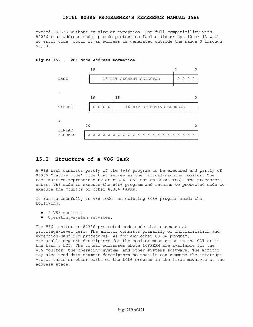
INTEL 80386 PROGRAMMER'S REFERENCE MANUAL 1986
Page 219 of 421
exceed 65,535 without causing an exception. For full compatibility with80286 real-address mode, pseudo-protection faults (interrupt 12 or 13 withno error code) occur if an address is generated outside the range 0 through65,535.
Figure 15-1. V86 Mode Address Formation
19 3 0 ╔═════════════════════════════════╪═════════╗ BASE ║ 16-BIT SEGMENT SELECTOR │ 0 0 0 0 ║ ╚═════════════════════════════════╪═════════╝
+ 19 15 0 ╔═════════╪═════════════════════════════════╗ OFFSET ║ 0 0 0 0 │ 16-BIT EFFECTIVE ADDRESS ║ ╚═════════╪═════════════════════════════════╝
= 20 0 LINEAR ╔═════════════════════════════════════════════╗ ADDRESS ║ X X X X X X X X X X X X X X X X X X X X X X ║ ╚═════════════════════════════════════════════╝
15.2 Structure of a V86 Task
A V86 task consists partly of the 8086 program to be executed and partly of80386 "native mode" code that serves as the virtual-machine monitor. Thetask must be represented by an 80386 TSS (not an 80286 TSS). The processorenters V86 mode to execute the 8086 program and returns to protected mode toexecute the monitor or other 80386 tasks.
To run successfully in V86 mode, an existing 8086 program needs thefollowing:
● A V86 monitor. ● Operating-system services.
The V86 monitor is 80386 protected-mode code that executes atprivilege-level zero. The monitor consists primarily of initialization andexception-handling procedures. As for any other 80386 program,executable-segment descriptors for the monitor must exist in the GDT or inthe task's LDT. The linear addresses above 10FFEFH are available for theV86 monitor, the operating system, and other systems software. The monitormay also need data-segment descriptors so that it can examine the interruptvector table or other parts of the 8086 program in the first megabyte of theaddress space.
INTEL 80386 PROGRAMMER'S REFERENCE MANUAL 1986
Page 220 of 421
In general, there are two options for implementing the 8086 operatingsystem:
1. The 8086 operating system may run as part of the 8086 code. This approach is desirable for any of the following reasons:
● The 8086 applications code modifies the operating system.
● There is not sufficient development time to reimplement the 8086 operating system as 80386 code.
2. The 8086 operating system may be implemented or emulated in the V86 monitor. This approach is desirable for any of the following reasons:
● Operating system functions can be more easily coordinated among several V86 tasks.
● The functions of the 8086 operating system can be easily emulated by calls to the 80386 operating system.
Note that, regardless of the approach chosen for implementing the 8086operating system, different V86 tasks may use different 8086 operatingsystems.
15.2.1 Using Paging for V86 Tasks
Paging is not necessary for a single V86 task, but paging is useful ornecessary for any of the following reasons:
● To create multiple V86 tasks. Each task must map the lower megabyte of linear addresses to different physical locations.
● To emulate the megabyte wrap. On members of the 8086 family, it is possible to specify addresses larger than one megabyte. For example, with a selector value of 0FFFFH and an offset of 0FFFFH, the effective address would be 10FFEFH (one megabyte + 65519). The 8086, which can form addresses only up to 20 bits long, truncates the high-order bit, thereby "wrapping" this address to 0FFEFH. The 80386, however, which can form addresses up to 32 bits long does not truncate such an address. If any 8086 programs depend on this addressing anomaly, the same effect can be achieved in a V86 task by mapping linear addresses between 100000H and 110000H and linear addresses between 0 and 10000H to the same physical addresses.
● To create a virtual address space larger than the physical address space.
● To share 8086 OS code or ROM code that is common to several 8086 programs that are executing simultaneously.
● To redirect or trap references to memory-mapped I/O devices.
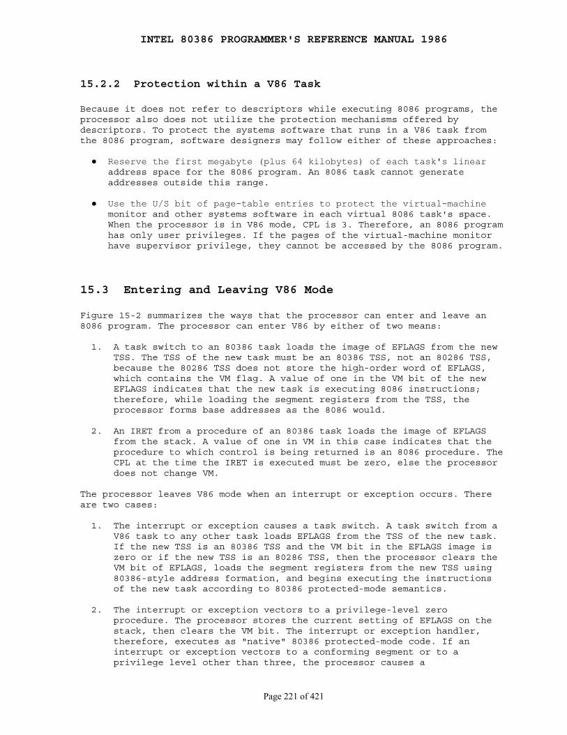
INTEL 80386 PROGRAMMER'S REFERENCE MANUAL 1986
Page 221 of 421
15.2.2 Protection within a V86 Task
Because it does not refer to descriptors while executing 8086 programs, theprocessor also does not utilize the protection mechanisms offered bydescriptors. To protect the systems software that runs in a V86 task fromthe 8086 program, software designers may follow either of these approaches:
● Reserve the first megabyte (plus 64 kilobytes) of each task's linear address space for the 8086 program. An 8086 task cannot generate addresses outside this range.
● Use the U/S bit of page-table entries to protect the virtual-machine monitor and other systems software in each virtual 8086 task's space. When the processor is in V86 mode, CPL is 3. Therefore, an 8086 program has only user privileges. If the pages of the virtual-machine monitor have supervisor privilege, they cannot be accessed by the 8086 program.
15.3 Entering and Leaving V86 Mode
Figure 15-2 summarizes the ways that the processor can enter and leave an8086 program. The processor can enter V86 by either of two means:
1. A task switch to an 80386 task loads the image of EFLAGS from the new TSS. The TSS of the new task must be an 80386 TSS, not an 80286 TSS, because the 80286 TSS does not store the high-order word of EFLAGS, which contains the VM flag. A value of one in the VM bit of the new EFLAGS indicates that the new task is executing 8086 instructions; therefore, while loading the segment registers from the TSS, the processor forms base addresses as the 8086 would.
2. An IRET from a procedure of an 80386 task loads the image of EFLAGS from the stack. A value of one in VM in this case indicates that the procedure to which control is being returned is an 8086 procedure. The CPL at the time the IRET is executed must be zero, else the processor does not change VM.
The processor leaves V86 mode when an interrupt or exception occurs. Thereare two cases:
1. The interrupt or exception causes a task switch. A task switch from a V86 task to any other task loads EFLAGS from the TSS of the new task. If the new TSS is an 80386 TSS and the VM bit in the EFLAGS image is zero or if the new TSS is an 80286 TSS, then the processor clears the VM bit of EFLAGS, loads the segment registers from the new TSS using 80386-style address formation, and begins executing the instructions of the new task according to 80386 protected-mode semantics.
2. The interrupt or exception vectors to a privilege-level zero procedure. The processor stores the current setting of EFLAGS on the stack, then clears the VM bit. The interrupt or exception handler, therefore, executes as "native" 80386 protected-mode code. If an interrupt or exception vectors to a conforming segment or to a privilege level other than three, the processor causes a
INTEL 80386 PROGRAMMER'S REFERENCE MANUAL 1986
Page 222 of 421
general-protection exception; the error code is the selector of the executable segment to which transfer was attempted.
Systems software does not manipulate the VM flag directly, but rathermanipulates the image of the EFLAGS register that is stored on the stack orin the TSS. The V86 monitor sets the VM flag in the EFLAGS image on thestack or in the TSS when first creating a V86 task. Exception and interrupthandlers can examine the VM flag on the stack. If the interrupted procedurewas executing in V86 mode, the handler may need to invoke the V86 monitor.
Figure 15-2. Entering and Leaving the 8086 Program
MODE TRANSITION DIAGRAM
╔═══════════╗ TASK SWITCH ║ INITIAL ║ ┌────────────────╢ ENTRY ║ │ OR IRET ╚═══════════╝ │ ▼ ╔══════════════╗ INTERRUPT, EXCEPTION ╔═════════════╗ ║ 8086 PROGRAM ╟─────────────────────────────►║ V86 MONITOR ║ ║ (V86 MODE) ║◄─────────────────────────────╢ (PROTECTED ║ ╚═══════╤══════╝ IRET ║ MODE) ║ ▲ │ ╚═════╤═══════╝ │ │ │ ▲ │ │ │ │ │ │ │ │ │ │TASK SWITCH ╔═══════════════════╗ TASK SWITCH │ │ └───────────►║ OTHER 80386 TASKS ║◄─────────┘ │ └──────────────╢ (PROTECTED MODE) ╟─────────────┘ TASK SWITCH ╚═══════════════════╝ TASK SWITCH
15.3.1 Transitions Through Task Switches
A task switch to or from a V86 task may be due to any of three causes:
1. An interrupt that vectors to a task gate. 2. An action of the scheduler of the 80386 operating system. 3. An IRET when the NT flag is set.
In any of these cases, the processor changes the VM bit in EFLAGS accordingto the image of EFLAGS in the new TSS. If the new TSS is an 80286 TSS, thehigh-order word of EFLAGS is not in the TSS; the processor clears VM in thiscase. The processor updates VM prior to loading the segment registers fromthe images in the new TSS. The new setting of VM determines whether theprocessor interprets the new segment-register images as 8086 selectors or80386/80286 selectors.
INTEL 80386 PROGRAMMER'S REFERENCE MANUAL 1986
Page 223 of 421
15.3.2 Transitions Through Trap Gates and Interrupt Gates
The processor leaves V86 mode as the result of an exception or interruptthat vectors via a trap or interrupt gate to a privilege-level zeroprocedure. The exception or interrupt handler returns to the 8086 code byexecuting an IRET.
Because it was designed for execution by an 8086 processor, an 8086 programin a V86 task will have an 8086-style interrupt table starting at linearaddress zero. However, the 80386 does not use this table directly. For allexceptions and interrupts that occur in V86 mode, the processor vectorsthrough the IDT. The IDT entry for an interrupt or exception that occurs ina V86 task must contain either:
● A task gate.
● An 80386 trap gate (type 14) or an 80386 interrupt gate (type 15), which must point to a nonconforming, privilege-level zero, code segment.
Interrupts and exceptions that have 80386 trap or interrupt gates in theIDT vector to the appropriate handler procedure at privilege-level zero. Thecontents of all the 8086 segment registers are stored on the PL 0 stack.Figure 15-3 shows the format of the PL 0 stack after an exception orinterrupt that occurs while a V86 task is executing an 8086 program.
After the processor stores all the 8086 segment registers on the PL 0stack, it loads all the segment registers with zeros before starting toexecute the handler procedure. This permits the interrupt handler to safelysave and restore the DS, ES, FS, and GS registers as 80386 selectors.Interrupt handlers that may be invoked in the context of either a regulartask or a V86 task, can use the same prolog and epilog code for registersaving regardless of the kind of task. Restoring zeros to these registersbefore execution of the IRET does not cause a trap in the interrupt handler.Interrupt procedures that expect values in the segment registers or thatreturn values via segment registers have to use the register images storedon the PL 0 stack. Interrupt handlers that need to know whether theinterrupt occurred in V86 mode can examine the VM bit in the stored EFLAGSimage.
An interrupt handler passes control to the V86 monitor if the VM bit is setin the EFLAGS image stored on the stack and the interrupt or exception isone that the monitor needs to handle. The V86 monitor may either:
● Handle the interrupt completely within the V86 monitor. ● Invoke the 8086 program's interrupt handler.
Reflecting an interrupt or exception back to the 8086 code involves thefollowing steps:
1. Refer to the 8086 interrupt vector to locate the appropriate handler procedure.
2. Store the state of the 8086 program on the privilege-level three stack.
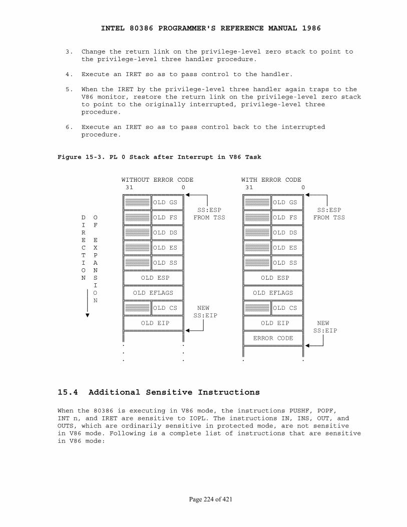
INTEL 80386 PROGRAMMER'S REFERENCE MANUAL 1986
Page 224 of 421
3. Change the return link on the privilege-level zero stack to point to the privilege-level three handler procedure.
4. Execute an IRET so as to pass control to the handler.
5. When the IRET by the privilege-level three handler again traps to the V86 monitor, restore the return link on the privilege-level zero stack to point to the originally interrupted, privilege-level three procedure.
6. Execute an IRET so as to pass control back to the interrupted procedure.
Figure 15-3. PL 0 Stack after Interrupt in V86 Task
WITHOUT ERROR CODE WITH ERROR CODE 31 0 31 0 ╔══════╦═══════╗◄────┐ ╔══════╦═══════╗◄────┐ ║▒▒▒▒▒▒║OLD GS ║ │ ║▒▒▒▒▒▒║OLD GS ║ │ ╠══════╬═══════╣ SS:ESP ╠══════╬═══════╣ SS:ESP D O ║▒▒▒▒▒▒║OLD FS ║ FROM TSS ║▒▒▒▒▒▒║OLD FS ║ FROM TSS I F ╠══════╬═══════╣ ╠══════╬═══════╣ R ║▒▒▒▒▒▒║OLD DS ║ ║▒▒▒▒▒▒║OLD DS ║ E E ╠══════╬═══════╣ ╠══════╬═══════╣ C X ║▒▒▒▒▒▒║OLD ES ║ ║▒▒▒▒▒▒║OLD ES ║ T P ╠══════╬═══════╣ ╠══════╬═══════╣ I A ║▒▒▒▒▒▒║OLD SS ║ ║▒▒▒▒▒▒║OLD SS ║ O N ╠══════╩═══════╣ ╠══════╩═══════╣ N S ║ OLD ESP ║ ║ OLD ESP ║ I ╠══════════════╣ ╠══════════════╣ │ O ║ OLD EFLAGS ║ ║ OLD EFLAGS ║ │ N ╠══════╦═══════╣ ╠══════╦═══════╣ │ ║▒▒▒▒▒▒║OLD CS ║ NEW ║▒▒▒▒▒▒║OLD CS ║ ▼ ╠══════╩═══════╣ SS:EIP ╠══════╩═══════╣ ║ OLD EIP ║ │ ║ OLD EIP ║ NEW ╠══════════════╣◄───┘ ╠══════════════╣ SS:EIP ║ ║ ║ ERROR CODE ║ │ · · ╠══════════════╣◄───┘ · · ║ ║ · · · ·
15.4 Additional Sensitive Instructions
When the 80386 is executing in V86 mode, the instructions PUSHF, POPF,INT n, and IRET are sensitive to IOPL. The instructions IN, INS, OUT, andOUTS, which are ordinarily sensitive in protected mode, are not sensitivein V86 mode. Following is a complete list of instructions that are sensitivein V86 mode:

INTEL 80386 PROGRAMMER'S REFERENCE MANUAL 1986
Page 225 of 421
CLI ── Clear Interrupt-Enable Flag STI ── Set Interrupt-Enable Flag LOCK ── Assert Bus-Lock Signal PUSHF ── Push Flags POPF ── Pop Flags INT n ── Software Interrupt RET ── Interrupt Return
CPL is always three in V86 mode; therefore, if IOPL < 3, these instructionswill trigger a general-protection exceptions. These instructions are madesensitive so that their functions can be simulated by the V86 monitor.
15.4.1 Emulating 8086 Operating System Calls
INT n is sensitive so that the V86 monitor can intercept calls to the8086 OS. Many 8086 operating systems are called by pushing parameters ontothe stack, then executing an INT n instruction. If IOPL < 3, INT ninstructions will be intercepted by the V86 monitor. The V86 monitor canthen emulate the function of the 8086 operating system or reflect theinterrupt back to the 8086 operating system in V86 mode.
15.4.2 Virtualizing the Interrupt-Enable Flag
When the processor is executing 8086 code in a V86 task, the instructionsPUSHF, POPF, and IRET are sensitive to IOPL so that the V86 monitor cancontrol changes to the interrupt-enable flag (IF). Other instructions thataffect IF (STI and CLI) are IOPL sensitive both in 8086 code and in80386/80386 code.
Many 8086 programs that were designed to execute on single-task systems setand clear IF to control interrupts. However, when these same programs areexecuted in a multitasking environment, such control of IF can bedisruptive. If IOPL is less than three, all instructions that change orinterrogate IF will trap to the V86 monitor. The V86 monitor can thencontrol IF in a manner that both suits the needs of the larger environmentand is transparent to the 8086 program.
15.5 Virtual I/O
Many 8086 programs that were designed to execute on single-task systems useI/O devices directly. However, when these same programs are executed in amultitasking environment, such use of devices can be disruptive. The 80386provides sufficient flexibility to control I/O in a manner that both suitsthe needs of the new environment and is transparent to the 8086 program.Designers may take any of several possible approaches to controlling I/O:
● Implement or emulate the 8086 operating system as an 80386 program and require the 8086 application to do I/O via software interrupts to the operating system, trapping all attempts to do I/O directly.
INTEL 80386 PROGRAMMER'S REFERENCE MANUAL 1986
Page 226 of 421
● Let the 8086 program take complete control of all I/O.
● Selectively trap and emulate references that a task makes to specific I/O ports.
● Trap or redirect references to memory-mapped I/O addresses.
The method of controlling I/O depends upon whether I/O ports are I/O mappedor memory mapped.
15.5.1 I/O-Mapped I/O
I/O-mapped I/O in V86 mode differs from protected mode only in that theprotection mechanism does not consult IOPL when executing the I/Oinstructions IN, INS, OUT, OUTS. Only the I/O permission bit map controlsthe right for V86 tasks to execute these I/O instructions.
The I/O permission map traps I/O instructions selectively depending on theI/O addresses to which they refer. The I/O permission bit map of each V86task determines which I/O addresses are trapped for that task. Because eachtask may have a different I/O permission bit map, the addresses trapped forone task may be different from those trapped for others. Refer to Chapter 8for more information about the I/O permission map.
15.5.2 Memory-Mapped I/O
In hardware designs that utilize memory-mapped I/O, the paging facilitiesof the 80386 can be used to trap or redirect I/O operations. Each task thatexecutes memory-mapped I/O must have a page (or pages) for the memory-mappedaddress space. The V86 monitor may control memory-mapped I/O by any ofthese means:
● Assign the memory-mapped page to appropriate physical addresses. Different tasks may have different physical addresses, thereby preventing the tasks from interfering with each other.
● Cause a trap to the monitor by forcing a page fault on the memory-mapped page. Read-only pages trap writes. Not-present pages trap both reads and writes.
Intervention for every I/O might be excessive for some kinds of I/Odevices. A page fault can still be used in this case to cause interventionon the first I/O operation. The monitor can then at least make sure that thetask has exclusive access to the device. Then the monitor can change thepage status to present and read/write, allowing subsequent I/O to proceed atfull speed.

INTEL 80386 PROGRAMMER'S REFERENCE MANUAL 1986
Page 227 of 421
15.5.3 Special I/O Buffers
Buffers of intelligent controllers (for example, a bit-mapped graphicsbuffer) can also be virtualized via page mapping. The linear space for thebuffer can be mapped to a different physical space for each virtual 8086task. The V86 monitor can then assume responsibility for spooling the dataor assigning the virtual buffer to the real buffer at appropriate times.
15.6 Differences From 8086
In general, V86 mode will correctly execute software designed for the 8086,8088, 80186, and 80188. Following is a list of the minor differences between8086 execution on the 80386 and on an 8086.
1. Instruction clock counts.
The 80386 takes fewer clocks for most instructions than the 8086/8088. The areas most likely to be affected are:
● Delays required by I/O devices between I/O operations.
● Assumed delays with 8086/8088 operating in parallel with an 8087.
2. Divide exceptions point to the DIV instruction.
Divide exceptions on the 80386 always leave the saved CS:IP value pointing to the instruction that failed. On the 8086/8088, the CS:IP value points to the next instruction.
3. Undefined 8086/8088 opcodes.
Opcodes that were not defined for the 8086/8088 will cause exception 6 or will execute one of the new instructions defined for the 80386.
4. Value written by PUSH SP.
The 80386 pushes a different value on the stack for PUSH SP than the 8086/8088. The 80386 pushes the value of SP before SP is incremented as part of the push operation; the 8086/8088 pushes the value of SP after it is incremented. If the value pushed is important, replace PUSH SP instructions with the following three instructions:
PUSH BP MOV BP, SP XCHG BP, [BP]
This code functions as the 8086/8088 PUSH SP instruction on the 80386.

INTEL 80386 PROGRAMMER'S REFERENCE MANUAL 1986
Page 228 of 421
5. Shift or rotate by more than 31 bits.
The 80386 masks all shift and rotate counts to the low-order five bits. This MOD 32 operation limits the count to a maximum of 31 bits, thereby limiting the time that interrupt response is delayed while the instruction is executing.
6. Redundant prefixes.
The 80386 sets a limit of 15 bytes on instruction length. The only way to violate this limit is by putting redundant prefixes before an instruction. Exception 13 occurs if the limit on instruction length is violated. The 8086/8088 has no instruction length limit.
7. Operand crossing offset 0 or 65,535.
On the 8086, an attempt to access a memory operand that crosses offset 65,535 (e.g., MOV a word to offset 65,535) or offset 0 (e.g., PUSH a word when SP = 1) causes the offset to wrap around modulo 65,536. The 80386 raises an exception in these cases──exception 13 if the segment is a data segment (i.e., if CS, DS, ES, FS, or GS is being used to address the segment), exception 12 if the segment is a stack segment (i.e., if SS is being used).
8. Sequential execution across offset 65,535.
On the 8086, if sequential execution of instructions proceeds past offset 65,535, the processor fetches the next instruction byte from offset 0 of the same segment. On the 80386, the processor raises exception 13 in such a case.
9. LOCK is restricted to certain instructions.
The LOCK prefix and its corresponding output signal should only be used to prevent other bus masters from interrupting a data movement operation. The 80386 always asserts the LOCK signal during an XCHG instruction with memory (even if the LOCK prefix is not used). LOCK may only be used with the following 80386 instructions when they update memory: BTS, BTR, BTC, XCHG, ADD, ADC, SUB, SBB, INC, DEC, AND, OR, XOR, NOT, and NEG. An undefined-opcode exception (interrupt 6) results from using LOCK before any other instruction.
10. Single-stepping external interrupt handlers.
The priority of the 80386 single-step exception is different from that of the 8086/8088. The change prevents an external interrupt handler from being single-stepped if the interrupt occurs while a program is being single-stepped. The 80386 single-step exception has higher priority that any external interrupt. The 80386 will still single-step through an interrupt handler invoked by the INT instructions or by an exception.
11. IDIV exceptions for quotients of 80H or 8000H.
The 80386 can generate the largest negative number as a quotient for the IDIV instruction. The 8086/8088 causes exception zero instead.
INTEL 80386 PROGRAMMER'S REFERENCE MANUAL 1986
Page 229 of 421
12. Flags in stack.
The setting of the flags stored by PUSHF, by interrupts, and by exceptions is different from that stored by the 8086 in bit positions 12 through 15. On the 8086 these bits are stored as ones, but in V86 mode bit 15 is always zero, and bits 14 through 12 reflect the last value loaded into them.
13. NMI interrupting NMI handlers.
After an NMI is recognized on the 80386, the NMI interrupt is masked until an IRET instruction is executed.
14. Coprocessor errors vector to interrupt 16.
Any 80386 system with a coprocessor must use interrupt vector 16 for the coprocessor error exception. If an 8086/8088 system uses another vector for the 8087 interrupt, both vectors should point to the coprocessor-error exception handler.
15. Numeric exception handlers should allow prefixes.
On the 80386, the value of CS:IP saved for coprocessor exceptions points at any prefixes before an ESC instruction. On 8086/8088 systems, the saved CS:IP points to the ESC instruction itself.
16. Coprocessor does not use interrupt controller.
The coprocessor error signal to the 80386 does not pass through an interrupt controller (an 8087 INT signal does). Some instructions in a coprocessor error handler may need to be deleted if they deal with the interrupt controller.
15.7 Differences From 80286 Real-Address Mode
The 80286 processor implements the bus lock function differently than the80386. This fact may or may not be apparent to 8086 programs, depending onhow the V86 monitor handles the LOCK prefix. LOCKed instructions aresensitive to IOPL; therefore, software designers can choose to emulate itsfunction. If, however, 8086 programs are allowed to execute LOCK directly,programs that use forms of memory locking specific to the 8086 may notexecute properly when transported to a specific application of the 80386.
The LOCK prefix and its corresponding output signal should only be used toprevent other bus masters from interrupting a data movement operation. LOCKmay only be used with the following 80386 instructions when they modifymemory. An undefined-opcode exception results from using LOCK before anyother instruction.
● Bit test and change: BTS, BTR, BTC. ● Exchange: XCHG. ● One-operand arithmetic and logical: INC, DEC, NOT, and NEG. ● Two-operand arithmetic and logical: ADD, ADC, SUB, SBB, AND, OR, XOR.
INTEL 80386 PROGRAMMER'S REFERENCE MANUAL 1986
Page 230 of 421
A locked instruction is guaranteed to lock only the area of memory definedby the destination operand, but may lock a larger memory area. For example,typical 8086 and 80286 configurations lock the entire physical memory space.With the 80386, the defined area of memory is guaranteed to be lockedagainst access by a processor executing a locked instruction on exactly thesame memory area, i.e., an operand with identical starting address andidentical length.
INTEL 80386 PROGRAMMER'S REFERENCE MANUAL 1986
Page 231 of 421
Chapter 16 Mixing 16-Bit and 32 Bit Code
────────────────────────────────────────────────────────────────────────────
The 80386 running in protected mode is a 32-bit microprocessor, but it isdesigned to support 16-bit processing at three levels:
1. Executing 8086/80286 16-bit programs efficiently with complete compatibility.
2. Mixing 16-bit modules with 32-bit modules.
3. Mixing 16-bit and 32-bit addresses and operands within one module.
The first level of support for 16-bit programs has already been discussedin Chapter 13, Chapter 14, and Chapter 15. This chapter shows how 16-bitand 32-bit modules can cooperate with one another, and how one module canutilize both 16-bit and 32-bit operands and addressing.
The 80386 functions most efficiently when it is possible to distinguishbetween pure 16-bit modules and pure 32-bit modules. A pure 16-bit modulehas these characteristics:
● All segments occupy 64 Kilobytes or less. ● Data items are either 8 bits or 16 bits wide. ● Pointers to code and data have 16-bit offsets. ● Control is transferred only among 16-bit segments.
A pure 32-bit module has these characteristics:
● Segments may occupy more than 64 Kilobytes (zero bytes to 4 gigabytes).
● Data items are either 8 bits or 32 bits wide.
● Pointers to code and data have 32-bit offsets.
● Control is transferred only among 32-bit segments.
Pure 16-bit modules do exist; they are the modules designed for 16-bitmicroprocessors. Pure 32-bit modules may exist in new programs designedexplicitly for the 80386. However, as systems designers move applicationsfrom 16-bit processors to the 32-bit 80386, it will not always be possibleto maintain these ideals of pure 16-bit or 32-bit modules. It may beexpedient to execute old 16-bit modules in a new 32-bit environment withoutmaking source-code changes to the old modules if any of the followingconditions is true:
● Modules will be converted one-by-one from 16-bit environments to 32-bit environments.
● Older, 16-bit compilers and software-development tools will be utilized in the new32-bit operating environment until new 32-bit versions can be created.
INTEL 80386 PROGRAMMER'S REFERENCE MANUAL 1986
Page 232 of 421
● The source code of 16-bit modules is not available for modification.
● The specific data structures used by a given module inherently utilize 16-bit words.
● The native word size of the source language is 16 bits.
On the 80386, 16-bit modules can be mixed with 32-bit modules. To design asystem that mixes 16- and 32-bit code requires an understanding of themechanisms that the 80386 uses to invoke and control its 32-bit and 16-bitfeatures.
16.1 How the 80386 Implements 16-Bit and 32-Bit Features
The features of the architecture that permit the 80386 to work equally wellwith 32-bit and 16-bit address and operand sizes include:
● The D-bit (default bit) of code-segment descriptors, which determines the default choice of operand-size and address-size for the instructions of a code segment. (In real-address mode and V86 mode, which do not use descriptors, the default is 16 bits.) A code segment whose D-bit is set is known as a USE32 segment; a code segment whose D-bit is zero is a USE16 segment. The D-bit eliminates the need to encode the operand size and address size in instructions when all instructions use operands and effective addresses of the same size.
● Instruction prefixes that explicitly override the default choice of operand size and address size (available in protected mode as well as in real-address mode and V86 mode).
● Separate 32-bit and 16-bit gates for intersegment control transfers (including call gates, interrupt gates, and trap gates). The operand size for the control transfer is determined by the type of gate, not by the D-bit or prefix of the transfer instruction.
● Registers that can be used both for 32-bit and 16-bit operands and effective-address calculations.
● The B-bit (big bit) of data-segment descriptors, which determines the size of stack pointer (32-bit ESP or 16-bit SP) used by the CPU for implicit stack references.
16.2 Mixing 32-Bit and 16-Bit Operations
The 80386 has two instruction prefixes that allow mixing of 32-bit and16-bit operations within one segment:
● The operand-size prefix (66H) ● The address-size prefix (67H)

INTEL 80386 PROGRAMMER'S REFERENCE MANUAL 1986
Page 233 of 421
These prefixes reverse the default size selected by the D-bit. For example,the processor can interpret the word-move instruction MOV mem, reg in any offour ways:
● In a USE32 segment:
1. Normally moves 32 bits from a 32-bit register to a 32-bit effective address in memory.
2. If preceded by an operand-size prefix, moves 16 bits from a 16-bit register to 32-bit effective address in memory.
3. If preceded by an address-size prefix, moves 32 bits from a 32-bit register to a16-bit effective address in memory.
4. If preceded by both an address-size prefix and an operand-size prefix, moves 16 bits from a 16-bit register to a 16-bit effective address in memory.
● In a USE16 segment:
1. Normally moves 16 bits from a 16-bit register to a 16-bit effective address in memory.
2. If preceded by an operand-size prefix, moves 32 bits from a 32-bit register to 16-bit effective address in memory.
3. If preceded by an address-size prefix, moves 16 bits from a 16-bit register to a32-bit effective address in memory.
4. If preceded by both an address-size prefix and an operand-size prefix, moves 32 bits from a 32-bit register to a 32-bit effective address in memory.
These examples illustrate that any instruction can generate any combinationof operand size and address size regardless of whether the instruction is ina USE16 or USE32 segment. The choice of the USE16 or USE32 attribute for acode segment is based upon these criteria:
1. The need to address instructions or data in segments that are larger than 64 Kilobytes.
2. The predominant size of operands.
3. The addressing modes desired. (Refer to Chapter 17 for an explanation of the additional addressing modes that are available when 32-bit addressing is used.)
Choosing a setting of the D-bit that is contrary to the predominant size ofoperands requires the generation of an excessive number of operand-sizeprefixes.
16.3 Sharing Data Segments Among Mixed Code Segments
Because the choice of operand size and address size is defined in codesegments and their descriptors, data segments can be shared freely among
INTEL 80386 PROGRAMMER'S REFERENCE MANUAL 1986
Page 234 of 421
both USE16 and USE32 code segments. The only limitation is the one imposedby pointers with 16-bit offsets, which can only point to the first 64Kilobytes of a segment. When a data segment that contains more than 64Kilobytes is to be shared among USE32 and USE16 segments, the data that isto be accessed by the USE16 segments must be located within the first 64Kilobytes.
A stack that spans addresses less than 64K can be shared by both USE16 andUSE32 code segments. This class of stacks includes:
● Stacks in expand-up segments with G=0 and B=0.
● Stacks in expand-down segments with G=0 and B=0.
● Stacks in expand-up segments with G=1 and B=0, in which the stack is contained completely within the lower 64 Kilobytes. (Offsets greater than 64K can be used for data, other than the stack, that is not shared.)
The B-bit of a stack segment cannot, in general, be used to change the sizeof stack used by a USE16 code segment. The size of stack pointer used by theprocessor for implicit stack references is controlled by the B-bit of thedata-segment descriptor for the stack. Implicit references are those causedby interrupts, exceptions, and instructions such as PUSH, POP, CALL, andRET. One might be tempted, therefore, to try to increase beyond 64K thesize of the stack used by 16-bit code simply by supplying a larger stacksegment with the B-bit set. However, the B-bit does not control explicitstack references, such as accesses to parameters or local variables. A USE16code segment can utilize a "big" stack only if the code is modified so thatall explicit references to the stack are preceded by the address-sizeprefix, causing those references to use 32-bit addressing.
In big, expand-down segments (B=1, G=1, and E=1), all offsets are greaterthan 64K, therefore USE16 code cannot utilize such a stack segment unlessthe code segment is modified to employ 32-bit addressing. (Refer to Chapter6 for a review of the B, G, and E bits.)
16.4 Transferring Control Among Mixed Code Segments
When transferring control among procedures in USE16 and USE32 codesegments, programmers must be aware of three points:
● Addressing limitations imposed by pointers with 16-bit offsets.
● Matching of operand-size attribute in effect for the CALL/RET pair and theInterrupt/IRET pair so as to manage the stack correctly.
● Translation of parameters, especially pointer parameters.
Clearly, 16-bit effective addresses cannot be used to address data or codelocated beyond 64K in a 32-bit segment, nor can large 32-bit parameters besqueezed into a 16-bit word; however, except for these obvious limits, mostinterfacing problems between 16-bit and 32-bit modules can be solved. Somesolutions involve inserting interface procedures between the procedures inquestion.
INTEL 80386 PROGRAMMER'S REFERENCE MANUAL 1986
Page 235 of 421
16.4.1 Size of Code-Segment Pointer
For control-transfer instructions that use a pointer to identify the nextinstruction (i.e., those that do not use gates), the size of the offsetportion of the pointer is determined by the operand-size attribute. Theimplications of the use of two different sizes of code-segment pointer are:
● JMP, CALL, or RET from 32-bit segment to 16-bit segment is always possible using a 32-bit operand size.
● JMP, CALL, or RET from 16-bit segment using a 16-bit operand size cannot address the target in a 32-bit segment if the address of the target is greater than 64K.
An interface procedure can enable transfers from USE16 segments to 32-bitaddresses beyond 64K without requiring modifications any more extensive thanrelinking or rebinding the old programs. The requirements for such aninterface procedure are discussed later in this chapter.
16.4.2 Stack Management for Control Transfers
Because stack management is different for 16-bit CALL/RET than for 32-bitCALL/RET, the operand size of RET must match that of CALL. (Refer to Figure16-1.) A 16-bit CALL pushes the 16-bit IP and (for calls between privilegelevels) the 16-bit SP register. The corresponding RET must also use a 16-bitoperand size to POP these 16-bit values from the stack into the 16-bitregisters. A 32-bit CALL pushes the 32-bit EIP and (for interlevel calls)the 32-bit ESP register. The corresponding RET must also use a 32-bitoperand size to POP these 32-bit values from the stack into the 32-bitregisters. If the two halves of a CALL/RET pair do not have matching operandsizes, the stack will not be managed correctly and the values of theinstruction pointer and stack pointer will not be restored to correctvalues.
When the CALL and its corresponding RET are in segments that have D-bitswith the same values (i.e., both have 32-bit defaults or both have 16-bitdefaults), there is no problem. When the CALL and its corresponding RET arein segments that have different D-bit values, however, programmers (orprogram development software) must ensure that the CALL and RET match.
There are three ways to cause a 16-bit procedure to execute a 32-bit call:
1. Use a 16-bit call to a 32-bit interface procedure that then uses a 32-bit call to invoke the intended target.
2. Bind the 16-bit call to a 32-bit call gate.
3. Modify the 16-bit procedure, inserting an operand-size prefix before the call, thereby changing it to a 32-bit call.
Likewise, there are three ways to cause a 32-bit procedure to execute a16-bit call:
1. Use a 32-bit call to a 32-bit interface procedure that then uses a 16-bit call to invoke the intended target.
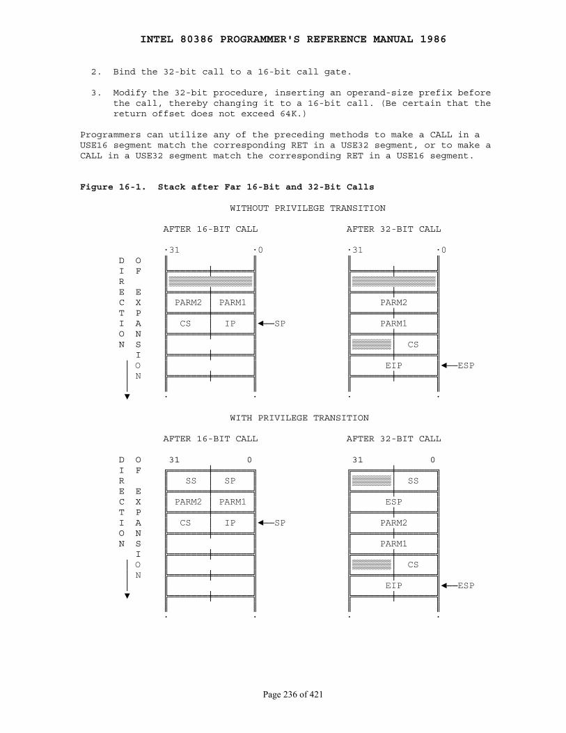
INTEL 80386 PROGRAMMER'S REFERENCE MANUAL 1986
Page 236 of 421
2. Bind the 32-bit call to a 16-bit call gate.
3. Modify the 32-bit procedure, inserting an operand-size prefix before the call, thereby changing it to a 16-bit call. (Be certain that the return offset does not exceed 64K.)
Programmers can utilize any of the preceding methods to make a CALL in aUSE16 segment match the corresponding RET in a USE32 segment, or to make aCALL in a USE32 segment match the corresponding RET in a USE16 segment.
Figure 16-1. Stack after Far 16-Bit and 32-Bit Calls
WITHOUT PRIVILEGE TRANSITION
AFTER 16-BIT CALL AFTER 32-BIT CALL
·31 ·0 ·31 ·0 D O ║ ║ ║ ║ I F ╠═══════╪═══════╣ ╠═══════╪═══════╣ R ║▒▒▒▒▒▒▒▒▒▒▒▒▒▒▒║ ║▒▒▒▒▒▒▒▒▒▒▒▒▒▒▒║ E E ╠═══════╪═══════╣ ╠═══════╪═══════╣ C X ║ PARM2 │ PARM1 ║ ║ PARM2 ║ T P ╠═══════╪═══════╣ ╠═══════╪═══════╣ I A ║ CS │ IP ║◄──SP ║ PARM1 ║ O N ╠═══════╪═══════╣ ╠═══════╪═══════╣ N S ║ ║ ║▒▒▒▒▒▒▒│ CS ║ I ╠═══════╪═══════╣ ╠═══════╪═══════╣ │ O ║ ║ ║ EIP ║◄──ESP │ N ╠═══════╪═══════╣ ╠═══════╪═══════╣ │ ║ ║ ║ ║ ▼ · · · ·
WITH PRIVILEGE TRANSITION
AFTER 16-BIT CALL AFTER 32-BIT CALL
D O 31 0 31 0 I F ╔═══════╪═══════╗ ╔═══════╪═══════╗ R ║ SS │ SP ║ ║▒▒▒▒▒▒▒│ SS ║ E E ╠═══════╪═══════╣ ╠═══════╪═══════╣ C X ║ PARM2 │ PARM1 ║ ║ ESP ║ T P ╠═══════╪═══════╣ ╠═══════╪═══════╣ I A ║ CS │ IP ║◄──SP ║ PARM2 ║ O N ╠═══════╪═══════╣ ╠═══════╪═══════╣ N S ║ ║ ║ PARM1 ║ I ╠═══════╪═══════╣ ╠═══════╪═══════╣ │ O ║ ║ ║▒▒▒▒▒▒▒│ CS ║ │ N ╠═══════╪═══════╣ ╠═══════╪═══════╣ │ ║ ║ ║ EIP ║◄──ESP ▼ ╠═══════╪═══════╣ ╠═══════╪═══════╣ ║ ║ ║ ║ · · · ·
INTEL 80386 PROGRAMMER'S REFERENCE MANUAL 1986
Page 237 of 421
16.4.2.1 Controlling the Operand-Size for a Call
When the selector of the pointer referenced by a CALL instruction selects asegment descriptor, the operand-size attribute in effect for the CALLinstruction is determined by the D-bit in the segment descriptor and by anyoperand-size instruction prefix.
When the selector of the pointer referenced by a CALL instruction selects agate descriptor, the type of call is determined by the type of call gate. Acall via an 80286 call gate (descriptor type 4) always has a 16-bitoperand-size attribute; a call via an 80386 call gate (descriptor type 12)always has a 32-bit operand-size attribute. The offset of the targetprocedure is taken from the gate descriptor; therefore, even a 16-bitprocedure can call a procedure that is located more than 64 kilobytes fromthe base of a 32-bit segment, because a 32-bit call gate contains a 32-bittarget offset.
An unmodified 16-bit code segment that has run successfully on an 8086 orreal-mode 80286 will always have a D-bit of zero and will not useoperand-size override prefixes; therefore, it will always execute 16-bitversions of CALL. The only modification needed to make a16-bit procedureeffect a 32-bit call is to relink the call to an 80386 call gate.
16.4.2.2 Changing Size of Call
When adding 32-bit gates to 16-bit procedures, it is important to considerthe number of parameters. The count field of the gate descriptor specifiesthe size of the parameter string to copy from the current stack to the stackof the more privileged procedure. The count field of a 16-bit gate specifiesthe number of words to be copied, whereas the count field of a 32-bit gatespecifies the number of doublewords to be copied; therefore, the 16-bitprocedure must use an even number of words as parameters.
16.4.3 Interrupt Control Transfers
With a control transfer due to an interrupt or exception, a gate is alwaysinvolved. The operand-size attribute for the interrupt is determined by thetype of IDT gate.
A 386 interrupt or trap gate (descriptor type 14 or 15) to a 32-bitinterrupt procedure can be used to interrupt either 32-bit or 16-bitprocedures. However, it is not generally feasible to permit an interrupt orexception to invoke a 16-bit handler procedure when 32-bit code isexecuting, because a 16-bit interrupt procedure has a return offset of only16-bits on its stack. If the 32-bit procedure is executing at an addressgreater than 64K, the 16-bit interrupt procedure cannot return correctly.
INTEL 80386 PROGRAMMER'S REFERENCE MANUAL 1986
Page 238 of 421
16.4.4 Parameter Translation
When segment offsets or pointers (which contain segment offsets) are passedas parameters between 16-bit and 32-bit procedures, some translation isrequired. Clearly, if a 32-bit procedure passes a pointer to data locatedbeyond 64K to a 16-bit procedure, the 16-bit procedure cannot utilize it.Beyond this natural limitation, an interface procedure can perform anyformat conversion between 32-bit and 16-bit pointers that may be needed.
Parameters passed by value between 32-bit and 16-bit code may also requiretranslation between 32-bit and 16-bit formats. Such translation requirementsare application dependent. Systems designers should take care to limit therange of values passed so that such translations are possible.
16.4.5 The Interface Procedure
Interposing an interface procedure between 32-bit and 16-bit procedures canbe the solution to any of several interface requirements:
● Allowing procedures in 16-bit segments to transfer control to instructions located beyond 64K in 32-bit segments.
● Matching of operand size for CALL/RET.
● Parameter translation.
Interface procedures between USE32 and USE16 segments can be constructedwith these properties:
● The procedures reside in a code segment whose D-bit is set, indicating a default operand size of 32-bits.
● All entry points that may be called by 16-bit procedures have offsets that are actually less than 64K.
● All points to which called 16-bit procedures may return also lie within 64K.
The interface procedures do little more than call corresponding proceduresin other segments. There may be two kinds of procedures:
● Those that are called by 16-bit procedures and call 32-bit procedures. These interface procedures are called by 16-bit CALLs and use the operand-size prefix before RET instructions to cause a 16-bit RET. CALLs to 32-bit segments are 32-bit calls (by default, because the D-bit is set), and the 32-bit code returns with 32-bit RET instructions.
● Those that are called by 32-bit procedures and call 16-bit procedures. These interface procedures are called by 32-bit CALL instructions, and return with 32-bit RET instructions (by default, because the D-bit is set). CALLs to 16-bit procedures use the operand-size prefix; procedures in the 16-bit code return with 16-bit RET instructions.
INTEL 80386 PROGRAMMER'S REFERENCE MANUAL 1986
Page 239 of 421
PART IV INSTRUCTION SET
Chapter 17 80386 Instruction Set
────────────────────────────────────────────────────────────────────────────
This chapter presents instructions for the 80386 in alphabetical order. Foreach instruction, the forms are given for each operand combination,including object code produced, operands required, execution time, and adescription. For each instruction, there is an operational description and asummary of exceptions generated.
17.1 Operand-Size and Address-Size Attributes
When executing an instruction, the 80386 can address memory using either 16or 32-bit addresses. Consequently, each instruction that uses memoryaddresses has associated with it an address-size attribute of either 16 or32 bits. 16-bit addresses imply both the use of a 16-bit displacement inthe instruction and the generation of a 16-bit address offset (segmentrelative address) as the result of the effective address calculation.32-bit addresses imply the use of a 32-bit displacement and the generationof a 32-bit address offset. Similarly, an instruction that accesses words(16 bits) or doublewords (32 bits) has an operand-size attribute of either16 or 32 bits.
The attributes are determined by a combination of defaults, instructionprefixes, and (for programs executing in protected mode) size-specificationbits in segment descriptors.
17.1.1 Default Segment Attribute
For programs executed in protected mode, the D-bit in executable-segmentdescriptors determines the default attribute for both address size andoperand size. These default attributes apply to the execution of allinstructions in the segment. A value of zero in the D-bit sets the defaultaddress size and operand size to 16 bits; a value of one, to 32 bits.
Programs that execute in real mode or virtual-8086 mode have 16-bitaddresses and operands by default.
17.1.2 Operand-Size and Address-Size Instruction Prefixes
The internal encoding of an instruction can include two byte-long prefixes:the address-size prefix, 67H, and the operand-size prefix, 66H. (A latersection, "Instruction Format," shows the position of the prefixes in aninstruction's encoding.) These prefixes override the default segmentattributes for the instruction that follows. Table 17-1 shows the effect ofeach possible combination of defaults and overrides.

INTEL 80386 PROGRAMMER'S REFERENCE MANUAL 1986
Page 240 of 421
17.1.3 Address-Size Attribute for Stack
Instructions that use the stack implicitly (for example: POP EAX also havea stack address-size attribute of either 16 or 32 bits. Instructions with astack address-size attribute of 16 use the 16-bit SP stack pointer register;instructions with a stack address-size attribute of 32 bits use the 32-bitESP register to form the address of the top of the stack.
The stack address-size attribute is controlled by the B-bit of thedata-segment descriptor in the SS register. A value of zero in the B-bitselects a stack address-size attribute of 16; a value of one selects a stackaddress-size attribute of 32.
Table 17-1. Effective Size Attributes
Segment Default D = ... 0 0 0 0 1 1 1 1Operand-Size Prefix 66H N N Y Y N N Y YAddress-Size Prefix 67H N Y N Y N Y N Y
Effective Operand Size 16 16 32 32 32 32 16 16Effective Address Size 16 32 16 32 32 16 32 16
Y = Yes, this instruction prefix is presentN = No, this instruction prefix is not present
17.2 Instruction Format
All instruction encodings are subsets of the general instruction formatshown in Figure 17-1. Instructions consist of optional instructionprefixes, one or two primary opcode bytes, possibly an address specifierconsisting of the ModR/M byte and the SIB (Scale Index Base) byte, adisplacement, if required, and an immediate data field, if required.
Smaller encoding fields can be defined within the primary opcode oropcodes. These fields define the direction of the operation, the size of thedisplacements, the register encoding, or sign extension; encoding fieldsvary depending on the class of operation.
Most instructions that can refer to an operand in memory have an addressingform byte following the primary opcode byte(s). This byte, called the ModR/Mbyte, specifies the address form to be used. Certain encodings of the ModR/Mbyte indicate a second addressing byte, the SIB (Scale Index Base) byte,which follows the ModR/M byte and is required to fully specify theaddressing form.
Addressing forms can include a displacement immediately following eitherthe ModR/M or SIB byte. If a displacement is present, it can be 8-, 16- or32-bits.
If the instruction specifies an immediate operand, the immediate operandalways follows any displacement bytes. The immediate operand, if specified,is always the last field of the instruction.
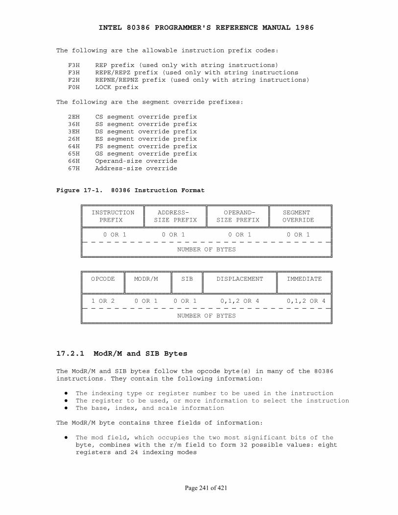
INTEL 80386 PROGRAMMER'S REFERENCE MANUAL 1986
Page 241 of 421
The following are the allowable instruction prefix codes:
F3H REP prefix (used only with string instructions) F3H REPE/REPZ prefix (used only with string instructions F2H REPNE/REPNZ prefix (used only with string instructions) F0H LOCK prefix
The following are the segment override prefixes:
2EH CS segment override prefix 36H SS segment override prefix 3EH DS segment override prefix 26H ES segment override prefix 64H FS segment override prefix 65H GS segment override prefix 66H Operand-size override 67H Address-size override
Figure 17-1. 80386 Instruction Format
╔═══════════════╦═══════════════╦═══════════════╦═══════════════╗ ║ INSTRUCTION ║ ADDRESS- ║ OPERAND- ║ SEGMENT ║ ║ PREFIX ║ SIZE PREFIX ║ SIZE PREFIX ║ OVERRIDE ║ ╠═══════════════╩═══════════════╩═══════════════╩═══════════════╣ ║ 0 OR 1 0 OR 1 0 OR 1 0 OR 1 ║ ╟─ ─ ─ ─ ─ ─ ─ ─ ─ ─ ─ ─ ─ ─ ─ ─ ─ ─ ─ ─ ─ ─ ─ ─ ─ ─ ─ ─ ─ ─ ─ ─╢ ║ NUMBER OF BYTES ║ ╚═══════════════════════════════════════════════════════════════╝
╔══════════╦═══════════╦═══════╦══════════════════╦═════════════╗ ║ OPCODE ║ MODR/M ║ SIB ║ DISPLACEMENT ║ IMMEDIATE ║ ║ ║ ║ ║ ║ ║ ╠══════════╩═══════════╩═══════╩══════════════════╩═════════════╣ ║ 1 OR 2 0 OR 1 0 OR 1 0,1,2 OR 4 0,1,2 OR 4 ║ ╟─ ─ ─ ─ ─ ─ ─ ─ ─ ─ ─ ─ ─ ─ ─ ─ ─ ─ ─ ─ ─ ─ ─ ─ ─ ─ ─ ─ ─ ─ ─ ─╢ ║ NUMBER OF BYTES ║ ╚═══════════════════════════════════════════════════════════════╝
17.2.1 ModR/M and SIB Bytes
The ModR/M and SIB bytes follow the opcode byte(s) in many of the 80386instructions. They contain the following information:
● The indexing type or register number to be used in the instruction ● The register to be used, or more information to select the instruction ● The base, index, and scale information
The ModR/M byte contains three fields of information:
● The mod field, which occupies the two most significant bits of the byte, combines with the r/m field to form 32 possible values: eight registers and 24 indexing modes
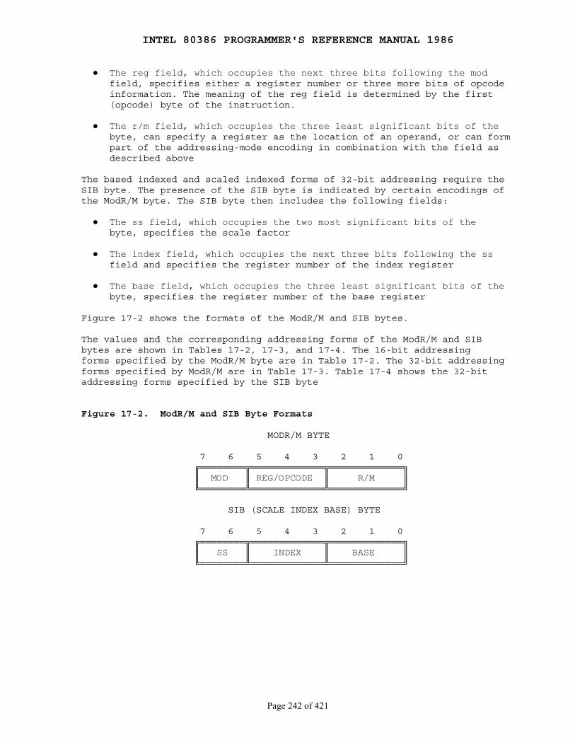
INTEL 80386 PROGRAMMER'S REFERENCE MANUAL 1986
Page 242 of 421
● The reg field, which occupies the next three bits following the mod field, specifies either a register number or three more bits of opcode information. The meaning of the reg field is determined by the first (opcode) byte of the instruction.
● The r/m field, which occupies the three least significant bits of the byte, can specify a register as the location of an operand, or can form part of the addressing-mode encoding in combination with the field as described above
The based indexed and scaled indexed forms of 32-bit addressing require theSIB byte. The presence of the SIB byte is indicated by certain encodings ofthe ModR/M byte. The SIB byte then includes the following fields:
● The ss field, which occupies the two most significant bits of the byte, specifies the scale factor
● The index field, which occupies the next three bits following the ss field and specifies the register number of the index register
● The base field, which occupies the three least significant bits of the byte, specifies the register number of the base register
Figure 17-2 shows the formats of the ModR/M and SIB bytes.
The values and the corresponding addressing forms of the ModR/M and SIBbytes are shown in Tables 17-2, 17-3, and 17-4. The 16-bit addressingforms specified by the ModR/M byte are in Table 17-2. The 32-bit addressingforms specified by ModR/M are in Table 17-3. Table 17-4 shows the 32-bitaddressing forms specified by the SIB byte
Figure 17-2. ModR/M and SIB Byte Formats
MODR/M BYTE
7 6 5 4 3 2 1 0 ╔════════╦═════════════╦═════════════╗ ║ MOD ║ REG/OPCODE ║ R/M ║ ╚════════╩═════════════╩═════════════╝
SIB (SCALE INDEX BASE) BYTE
7 6 5 4 3 2 1 0 ╔════════╦═════════════╦═════════════╗ ║ SS ║ INDEX ║ BASE ║ ╚════════╩═════════════╩═════════════╝
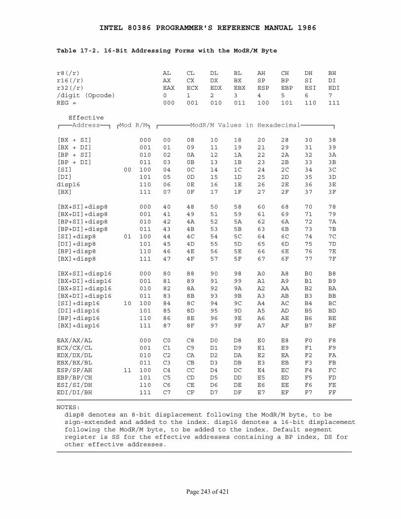
INTEL 80386 PROGRAMMER'S REFERENCE MANUAL 1986
Page 243 of 421
Table 17-2. 16-Bit Addressing Forms with the ModR/M Byte
r8(/r) AL CL DL BL AH CH DH BHr16(/r) AX CX DX BX SP BP SI DIr32(/r) EAX ECX EDX EBX ESP EBP ESI EDI/digit (Opcode) 0 1 2 3 4 5 6 7REG = 000 001 010 011 100 101 110 111
Effective┌───Address──┐ ┌Mod R/M┐ ┌────────ModR/M Values in Hexadecimal────────┐
[BX + SI] 000 00 08 10 18 20 28 30 38[BX + DI] 001 01 09 11 19 21 29 31 39[BP + SI] 010 02 0A 12 1A 22 2A 32 3A[BP + DI] 011 03 0B 13 1B 23 2B 33 3B[SI] 00 100 04 0C 14 1C 24 2C 34 3C[DI] 101 05 0D 15 1D 25 2D 35 3Ddisp16 110 06 0E 16 1E 26 2E 36 3E[BX] 111 07 0F 17 1F 27 2F 37 3F
[BX+SI]+disp8 000 40 48 50 58 60 68 70 78[BX+DI]+disp8 001 41 49 51 59 61 69 71 79[BP+SI]+disp8 010 42 4A 52 5A 62 6A 72 7A[BP+DI]+disp8 011 43 4B 53 5B 63 6B 73 7B[SI]+disp8 01 100 44 4C 54 5C 64 6C 74 7C[DI]+disp8 101 45 4D 55 5D 65 6D 75 7D[BP]+disp8 110 46 4E 56 5E 66 6E 76 7E[BX]+disp8 111 47 4F 57 5F 67 6F 77 7F
[BX+SI]+disp16 000 80 88 90 98 A0 A8 B0 B8[BX+DI]+disp16 001 81 89 91 99 A1 A9 B1 B9[BX+SI]+disp16 010 82 8A 92 9A A2 AA B2 BA[BX+DI]+disp16 011 83 8B 93 9B A3 AB B3 BB[SI]+disp16 10 100 84 8C 94 9C A4 AC B4 BC[DI]+disp16 101 85 8D 95 9D A5 AD B5 BD[BP]+disp16 110 86 8E 96 9E A6 AE B6 BE[BX]+disp16 111 87 8F 97 9F A7 AF B7 BF
EAX/AX/AL 000 C0 C8 D0 D8 E0 E8 F0 F8ECX/CX/CL 001 C1 C9 D1 D9 E1 E9 F1 F9EDX/DX/DL 010 C2 CA D2 DA E2 EA F2 FAEBX/BX/BL 011 C3 CB D3 DB E3 EB F3 FBESP/SP/AH 11 100 C4 CC D4 DC E4 EC F4 FCEBP/BP/CH 101 C5 CD D5 DD E5 ED F5 FDESI/SI/DH 110 C6 CE D6 DE E6 EE F6 FEEDI/DI/BH 111 C7 CF D7 DF E7 EF F7 FF───────────────────────────────────────────────────────────────────────────NOTES: disp8 denotes an 8-bit displacement following the ModR/M byte, to be sign-extended and added to the index. disp16 denotes a 16-bit displacement following the ModR/M byte, to be added to the index. Default segment register is SS for the effective addresses containing a BP index, DS for other effective addresses.───────────────────────────────────────────────────────────────────────────
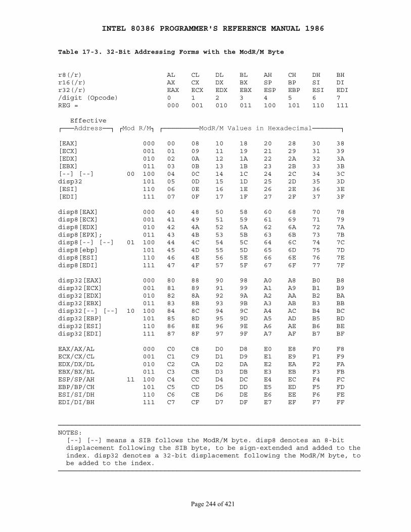
INTEL 80386 PROGRAMMER'S REFERENCE MANUAL 1986
Page 244 of 421
Table 17-3. 32-Bit Addressing Forms with the ModR/M Byte
r8(/r) AL CL DL BL AH CH DH BHr16(/r) AX CX DX BX SP BP SI DIr32(/r) EAX ECX EDX EBX ESP EBP ESI EDI/digit (Opcode) 0 1 2 3 4 5 6 7REG = 000 001 010 011 100 101 110 111
Effective┌───Address──┐ ┌Mod R/M┐ ┌─────────ModR/M Values in Hexadecimal───────┐
[EAX] 000 00 08 10 18 20 28 30 38[ECX] 001 01 09 11 19 21 29 31 39[EDX] 010 02 0A 12 1A 22 2A 32 3A[EBX] 011 03 0B 13 1B 23 2B 33 3B[--] [--] 00 100 04 0C 14 1C 24 2C 34 3Cdisp32 101 05 0D 15 1D 25 2D 35 3D[ESI] 110 06 0E 16 1E 26 2E 36 3E[EDI] 111 07 0F 17 1F 27 2F 37 3F
disp8[EAX] 000 40 48 50 58 60 68 70 78disp8[ECX] 001 41 49 51 59 61 69 71 79disp8[EDX] 010 42 4A 52 5A 62 6A 72 7Adisp8[EPX]; 011 43 4B 53 5B 63 6B 73 7Bdisp8[--] [--] 01 100 44 4C 54 5C 64 6C 74 7Cdisp8[ebp] 101 45 4D 55 5D 65 6D 75 7Ddisp8[ESI] 110 46 4E 56 5E 66 6E 76 7Edisp8[EDI] 111 47 4F 57 5F 67 6F 77 7F
disp32[EAX] 000 80 88 90 98 A0 A8 B0 B8disp32[ECX] 001 81 89 91 99 A1 A9 B1 B9disp32[EDX] 010 82 8A 92 9A A2 AA B2 BAdisp32[EBX] 011 83 8B 93 9B A3 AB B3 BBdisp32[--] [--] 10 100 84 8C 94 9C A4 AC B4 BCdisp32[EBP] 101 85 8D 95 9D A5 AD B5 BDdisp32[ESI] 110 86 8E 96 9E A6 AE B6 BEdisp32[EDI] 111 87 8F 97 9F A7 AF B7 BF
EAX/AX/AL 000 C0 C8 D0 D8 E0 E8 F0 F8ECX/CX/CL 001 C1 C9 D1 D9 E1 E9 F1 F9EDX/DX/DL 010 C2 CA D2 DA E2 EA F2 FAEBX/BX/BL 011 C3 CB D3 DB E3 EB F3 FBESP/SP/AH 11 100 C4 CC D4 DC E4 EC F4 FCEBP/BP/CH 101 C5 CD D5 DD E5 ED F5 FDESI/SI/DH 110 C6 CE D6 DE E6 EE F6 FEEDI/DI/BH 111 C7 CF D7 DF E7 EF F7 FF
───────────────────────────────────────────────────────────────────────────NOTES: [--] [--] means a SIB follows the ModR/M byte. disp8 denotes an 8-bit displacement following the SIB byte, to be sign-extended and added to the index. disp32 denotes a 32-bit displacement following the ModR/M byte, to be added to the index.───────────────────────────────────────────────────────────────────────────
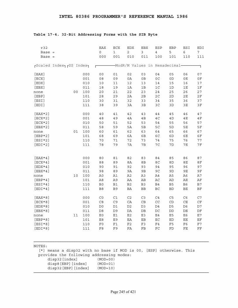
INTEL 80386 PROGRAMMER'S REFERENCE MANUAL 1986
Page 245 of 421
Table 17-4. 32-Bit Addressing Forms with the SIB Byte
r32 EAX ECX EDX EBX ESP EBP ESI EDI Base = 0 1 2 3 4 5 6 7 Base = 000 001 010 011 100 101 110 111
┌Scaled Index┐┌SS Index┐ ┌────────ModR/M Values in Hexadecimal────────┐
[EAX] 000 00 01 02 03 04 05 06 07[ECX] 001 08 09 0A 0B 0C 0D 0E 0F[EDX] 010 10 11 12 13 14 15 16 17[EBX] 011 18 19 1A 1B 1C 1D 1E 1Fnone 00 100 20 21 22 23 24 25 26 27[EBP] 101 28 29 2A 2B 2C 2D 2E 2F[ESI] 110 30 31 32 33 34 35 36 37[EDI] 111 38 39 3A 3B 3C 3D 3E 3F
[EAX*2] 000 40 41 42 43 44 45 46 47[ECX*2] 001 48 49 4A 4B 4C 4D 4E 4F[ECX*2] 010 50 51 52 53 54 55 56 57[EBX*2] 011 58 59 5A 5B 5C 5D 5E 5Fnone 01 100 60 61 62 63 64 65 66 67[EBP*2] 101 68 69 6A 6B 6C 6D 6E 6F[ESI*2] 110 70 71 72 73 74 75 76 77[EDI*2] 111 78 79 7A 7B 7C 7D 7E 7F
[EAX*4] 000 80 81 82 83 84 85 86 87[ECX*4] 001 88 89 8A 8B 8C 8D 8E 8F[EDX*4] 010 90 91 92 93 94 95 96 97[EBX*4] 011 98 89 9A 9B 9C 9D 9E 9Fnone 10 100 A0 A1 A2 A3 A4 A5 A6 A7[EBP*4] 101 A8 A9 AA AB AC AD AE AF[ESI*4] 110 B0 B1 B2 B3 B4 B5 B6 B7[EDI*4] 111 B8 B9 BA BB BC BD BE BF
[EAX*8] 000 C0 C1 C2 C3 C4 C5 C6 C7[ECX*8] 001 C8 C9 CA CB CC CD CE CF[EDX*8] 010 D0 D1 D2 D3 D4 D5 D6 D7[EBX*8] 011 D8 D9 DA DB DC DD DE DFnone 11 100 E0 E1 E2 E3 E4 E5 E6 E7[EBP*8] 101 E8 E9 EA EB EC ED EE EF[ESI*8] 110 F0 F1 F2 F3 F4 F5 F6 F7[EDI*8] 111 F8 F9 FA FB FC FD FE FF
───────────────────────────────────────────────────────────────────────────NOTES: [*] means a disp32 with no base if MOD is 00, [ESP] otherwise. This provides the following addressing modes: disp32[index] (MOD=00) disp8[EBP][index] (MOD=01) disp32[EBP][index] (MOD=10)───────────────────────────────────────────────────────────────────────────
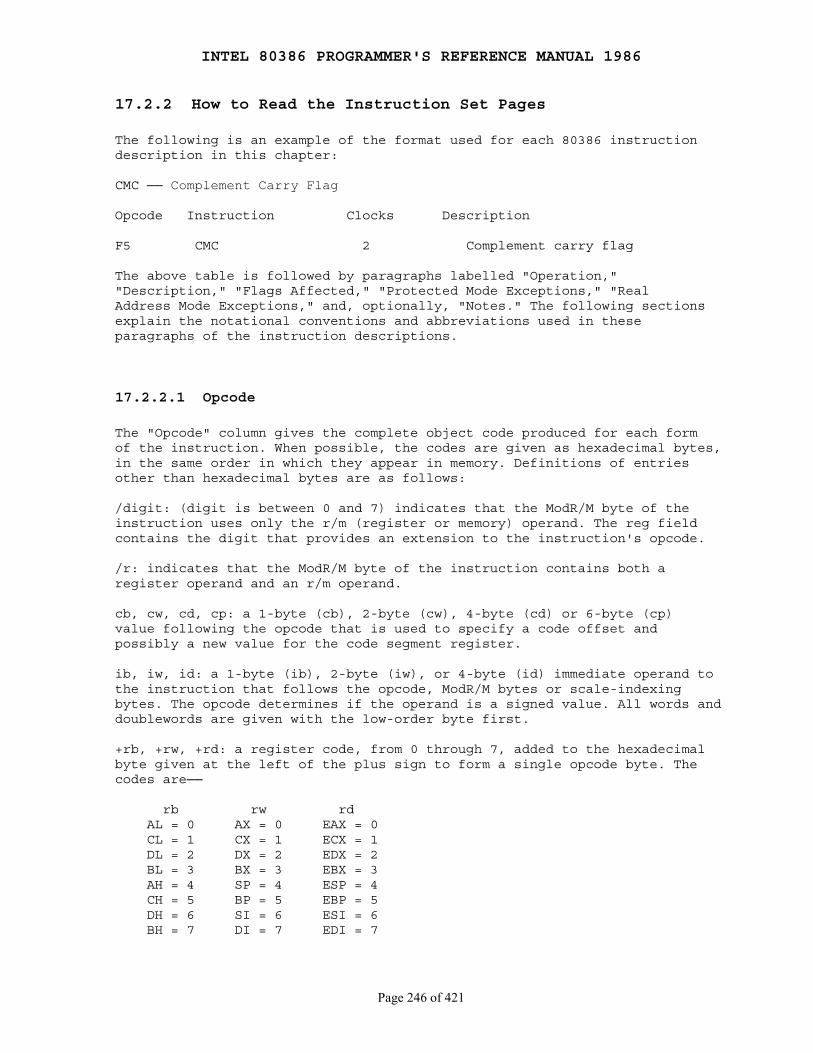
INTEL 80386 PROGRAMMER'S REFERENCE MANUAL 1986
Page 246 of 421
17.2.2 How to Read the Instruction Set Pages
The following is an example of the format used for each 80386 instructiondescription in this chapter:
CMC ── Complement Carry Flag
Opcode Instruction Clocks Description
F5 CMC 2 Complement carry flag
The above table is followed by paragraphs labelled "Operation,""Description," "Flags Affected," "Protected Mode Exceptions," "RealAddress Mode Exceptions," and, optionally, "Notes." The following sectionsexplain the notational conventions and abbreviations used in theseparagraphs of the instruction descriptions.
17.2.2.1 Opcode
The "Opcode" column gives the complete object code produced for each formof the instruction. When possible, the codes are given as hexadecimal bytes,in the same order in which they appear in memory. Definitions of entriesother than hexadecimal bytes are as follows:
/digit: (digit is between 0 and 7) indicates that the ModR/M byte of theinstruction uses only the r/m (register or memory) operand. The reg fieldcontains the digit that provides an extension to the instruction's opcode.
/r: indicates that the ModR/M byte of the instruction contains both aregister operand and an r/m operand.
cb, cw, cd, cp: a 1-byte (cb), 2-byte (cw), 4-byte (cd) or 6-byte (cp)value following the opcode that is used to specify a code offset andpossibly a new value for the code segment register.
ib, iw, id: a 1-byte (ib), 2-byte (iw), or 4-byte (id) immediate operand tothe instruction that follows the opcode, ModR/M bytes or scale-indexingbytes. The opcode determines if the operand is a signed value. All words anddoublewords are given with the low-order byte first.
+rb, +rw, +rd: a register code, from 0 through 7, added to the hexadecimalbyte given at the left of the plus sign to form a single opcode byte. Thecodes are──
rb rw rd AL = 0 AX = 0 EAX = 0 CL = 1 CX = 1 ECX = 1 DL = 2 DX = 2 EDX = 2 BL = 3 BX = 3 EBX = 3 AH = 4 SP = 4 ESP = 4 CH = 5 BP = 5 EBP = 5 DH = 6 SI = 6 ESI = 6 BH = 7 DI = 7 EDI = 7
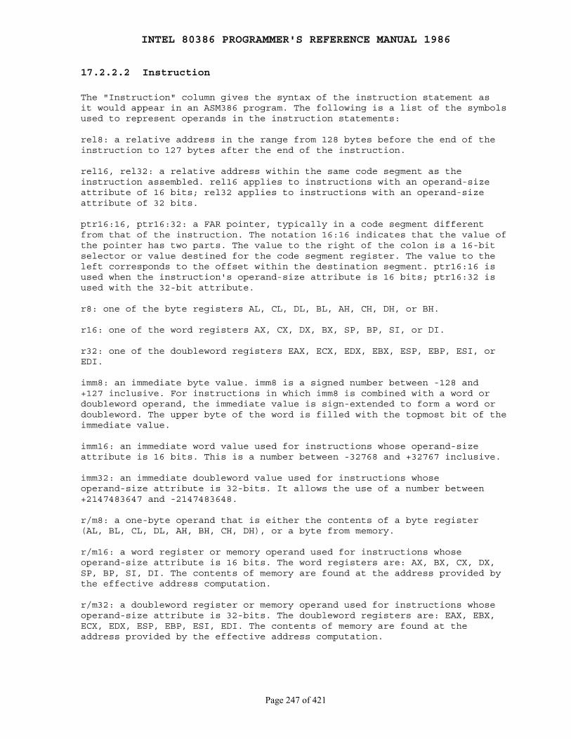
INTEL 80386 PROGRAMMER'S REFERENCE MANUAL 1986
Page 247 of 421
17.2.2.2 Instruction
The "Instruction" column gives the syntax of the instruction statement asit would appear in an ASM386 program. The following is a list of the symbolsused to represent operands in the instruction statements:
rel8: a relative address in the range from 128 bytes before the end of theinstruction to 127 bytes after the end of the instruction.
rel16, rel32: a relative address within the same code segment as theinstruction assembled. rel16 applies to instructions with an operand-sizeattribute of 16 bits; rel32 applies to instructions with an operand-sizeattribute of 32 bits.
ptr16:16, ptr16:32: a FAR pointer, typically in a code segment differentfrom that of the instruction. The notation 16:16 indicates that the value ofthe pointer has two parts. The value to the right of the colon is a 16-bitselector or value destined for the code segment register. The value to theleft corresponds to the offset within the destination segment. ptr16:16 isused when the instruction's operand-size attribute is 16 bits; ptr16:32 isused with the 32-bit attribute.
r8: one of the byte registers AL, CL, DL, BL, AH, CH, DH, or BH.
r16: one of the word registers AX, CX, DX, BX, SP, BP, SI, or DI.
r32: one of the doubleword registers EAX, ECX, EDX, EBX, ESP, EBP, ESI, orEDI.
imm8: an immediate byte value. imm8 is a signed number between -128 and+127 inclusive. For instructions in which imm8 is combined with a word ordoubleword operand, the immediate value is sign-extended to form a word ordoubleword. The upper byte of the word is filled with the topmost bit of theimmediate value.
imm16: an immediate word value used for instructions whose operand-sizeattribute is 16 bits. This is a number between -32768 and +32767 inclusive.
imm32: an immediate doubleword value used for instructions whoseoperand-size attribute is 32-bits. It allows the use of a number between+2147483647 and -2147483648.
r/m8: a one-byte operand that is either the contents of a byte register(AL, BL, CL, DL, AH, BH, CH, DH), or a byte from memory.
r/m16: a word register or memory operand used for instructions whoseoperand-size attribute is 16 bits. The word registers are: AX, BX, CX, DX,SP, BP, SI, DI. The contents of memory are found at the address provided bythe effective address computation.
r/m32: a doubleword register or memory operand used for instructions whoseoperand-size attribute is 32-bits. The doubleword registers are: EAX, EBX,ECX, EDX, ESP, EBP, ESI, EDI. The contents of memory are found at theaddress provided by the effective address computation.
INTEL 80386 PROGRAMMER'S REFERENCE MANUAL 1986
Page 248 of 421
m8: a memory byte addressed by DS:SI or ES:DI (used only by stringinstructions).
m16: a memory word addressed by DS:SI or ES:DI (used only by stringinstructions).
m32: a memory doubleword addressed by DS:SI or ES:DI (used only by stringinstructions).
m16:16, M16:32: a memory operand containing a far pointer composed of twonumbers. The number to the left of the colon corresponds to the pointer'ssegment selector. The number to the right corresponds to its offset.
m16 & 32, m16 & 16, m32 & 32: a memory operand consisting of data item pairswhose sizes are indicated on the left and the right side of the ampersand.All memory addressing modes are allowed. m16 & 16 and m32 & 32 operands areused by the BOUND instruction to provide an operand containing an upper andlower bounds for array indices. m16 & 32 is used by LIDT and LGDT toprovide a word with which to load the limit field, and a doubleword withwhich to load the base field of the corresponding Global and InterruptDescriptor Table Registers.
moffs8, moffs16, moffs32: (memory offset) a simple memory variable of typeBYTE, WORD, or DWORD used by some variants of the MOV instruction. Theactual address is given by a simple offset relative to the segment base. NoModR/M byte is used in the instruction. The number shown with moffsindicates its size, which is determined by the address-size attribute of theinstruction.
Sreg: a segment register. The segment register bit assignments are ES=0,CS=1, SS=2, DS=3, FS=4, and GS=5.
17.2.2.3 Clocks
The "Clocks" column gives the number of clock cycles the instruction takesto execute. The clock count calculations makes the following assumptions:
● The instruction has been prefetched and decoded and is ready for execution.
● Bus cycles do not require wait states.
● There are no local bus HOLD requests delaying processor access to the bus.
● No exceptions are detected during instruction execution.
● Memory operands are aligned.
Clock counts for instructions that have an r/m (register or memory) operandare separated by a slash. The count to the left is used for a registeroperand; the count to the right is used for a memory operand.
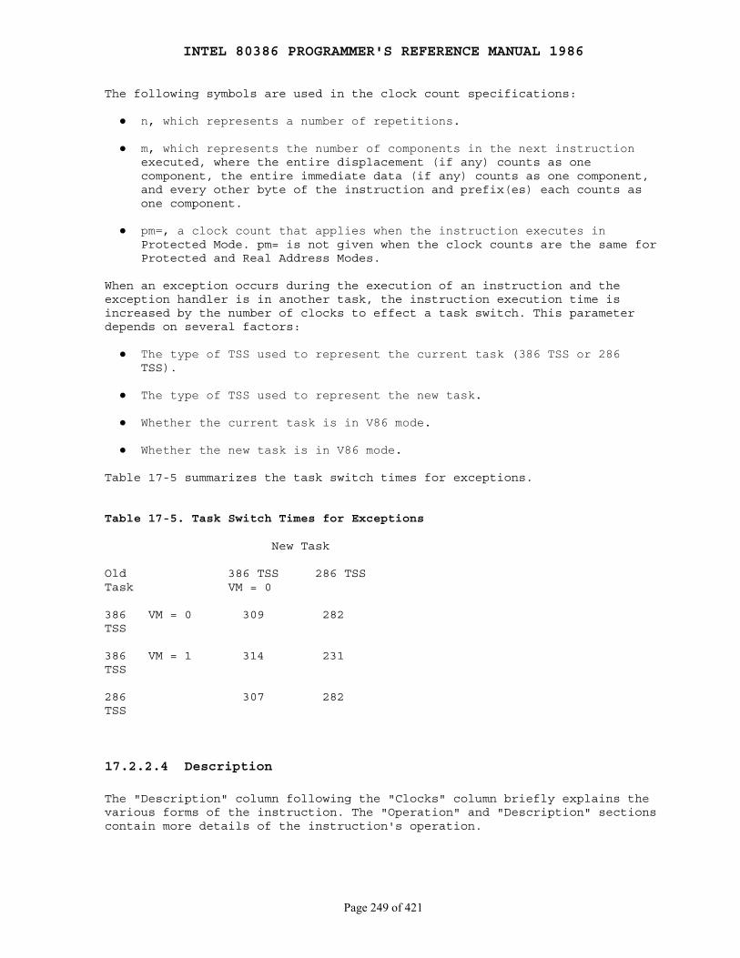
INTEL 80386 PROGRAMMER'S REFERENCE MANUAL 1986
Page 249 of 421
The following symbols are used in the clock count specifications:
● n, which represents a number of repetitions.
● m, which represents the number of components in the next instruction executed, where the entire displacement (if any) counts as one component, the entire immediate data (if any) counts as one component, and every other byte of the instruction and prefix(es) each counts as one component.
● pm=, a clock count that applies when the instruction executes in Protected Mode. pm= is not given when the clock counts are the same for Protected and Real Address Modes.
When an exception occurs during the execution of an instruction and theexception handler is in another task, the instruction execution time isincreased by the number of clocks to effect a task switch. This parameterdepends on several factors:
● The type of TSS used to represent the current task (386 TSS or 286 TSS).
● The type of TSS used to represent the new task.
● Whether the current task is in V86 mode.
● Whether the new task is in V86 mode.
Table 17-5 summarizes the task switch times for exceptions.
Table 17-5. Task Switch Times for Exceptions
New Task
Old 386 TSS 286 TSSTask VM = 0
386 VM = 0 309 282TSS
386 VM = 1 314 231TSS
286 307 282TSS
17.2.2.4 Description
The "Description" column following the "Clocks" column briefly explains thevarious forms of the instruction. The "Operation" and "Description" sectionscontain more details of the instruction's operation.
INTEL 80386 PROGRAMMER'S REFERENCE MANUAL 1986
Page 250 of 421
17.2.2.5 Operation
The "Operation" section contains an algorithmic description of theinstruction which uses a notation similar to the Algol or Pascal language.The algorithms are composed of the following elements:
Comments are enclosed within the symbol pairs "(*" and "*)".
Compound statements are enclosed between the keywords of the "if" statement(IF, THEN, ELSE, FI) or of the "do" statement (DO, OD), or of the "case"statement (CASE ... OF, ESAC).
A register name implies the contents of the register. A register nameenclosed in brackets implies the contents of the location whose address iscontained in that register. For example, ES:[DI] indicates the contents ofthe location whose ES segment relative address is in register DI. [SI]indicates the contents of the address contained in register SI relative toSI's default segment (DS) or overridden segment.
Brackets also used for memory operands, where they mean that the contentsof the memory location is a segment-relative offset. For example, [SRC]indicates that the contents of the source operand is a segment-relativeoffset.
A ← B; indicates that the value of B is assigned to A.
The symbols =, ≠, ≥, and ≤ are relational operators used to compare twovalues, meaning equal, not equal, greater or equal, less or equal,respectively. A relational expression such as A = B is TRUE if the value ofA is equal to B; otherwise it is FALSE.
The following identifiers are used in the algorithmic descriptions:
● OperandSize represents the operand-size attribute of the instruction, which is either 16 or 32 bits. AddressSize represents the address-size attribute, which is either 16 or 32 bits. For example,
IF instruction = CMPSW THEN OperandSize ← 16; ELSE IF instruction = CMPSD THEN OperandSize ← 32; FI; FI;
indicates that the operand-size attribute depends on the form of the CMPSinstruction used. Refer to the explanation of address-size and operand-sizeattributes at the beginning of this chapter for general guidelines on howthese attributes are determined.
● StackAddrSize represents the stack address-size attribute associated with the instruction, which has a value of 16 or 32 bits, as explained earlier in the chapter.
● SRC represents the source operand. When there are two operands, SRC is the one on the right.
INTEL 80386 PROGRAMMER'S REFERENCE MANUAL 1986
Page 251 of 421
● DEST represents the destination operand. When there are two operands, DEST is the one on the left.
● LeftSRC, RightSRC distinguishes between two operands when both are source operands.
● eSP represents either the SP register or the ESP register depending on the setting of the B-bit for the current stack segment.
The following functions are used in the algorithmic descriptions:
● Truncate to 16 bits(value) reduces the size of the value to fit in 16 bits by discarding the uppermost bits as needed.
● Addr(operand) returns the effective address of the operand (the result of the effective address calculation prior to adding the segment base).
● ZeroExtend(value) returns a value zero-extended to the operand-size attribute of the instruction. For example, if OperandSize = 32, ZeroExtend of a byte value of -10 converts the byte from F6H to doubleword with hexadecimal value 000000F6H. If the value passed to ZeroExtend and the operand-size attribute are the same size, ZeroExtend returns the value unaltered.
● SignExtend(value) returns a value sign-extended to the operand-size attribute of the instruction. For example, if OperandSize = 32, SignExtend of a byte containing the value -10 converts the byte from F6H to a doubleword with hexadecimal value FFFFFFF6H. If the value passed to SignExtend and the operand-size attribute are the same size, SignExtend returns the value unaltered.
● Push(value) pushes a value onto the stack. The number of bytes pushed is determined by the operand-size attribute of the instruction. The action of Push is as follows:
IF StackAddrSize = 16 THEN IF OperandSize = 16 THEN SP ← SP - 2; SS:[SP] ← value; (* 2 bytes assigned starting at byte address in SP *) ELSE (* OperandSize = 32 *) SP ← SP - 4; SS:[SP] ← value; (* 4 bytes assigned starting at byte address in SP *) FI; ELSE (* StackAddrSize = 32 *) IF OperandSize = 16 THEN ESP ← ESP - 2; SS:[ESP] ← value; (* 2 bytes assigned starting at byte address in ESP*) ELSE (* OperandSize = 32 *) ESP ← ESP - 4; SS:[ESP] ← value; (* 4 bytes assigned starting at byte address in ESP*)

INTEL 80386 PROGRAMMER'S REFERENCE MANUAL 1986
Page 252 of 421
FI; FI;
● Pop(value) removes the value from the top of the stack and returns it. The statement EAX ← Pop( ); assigns to EAX the 32-bit value that Pop took from the top of the stack. Pop will return either a word or a doubleword depending on the operand-size attribute. The action of Pop is as follows:
IF StackAddrSize = 16 THEN IF OperandSize = 16 THEN ret val ← SS:[SP]; (* 2-byte value *) SP ← SP + 2; ELSE (* OperandSize = 32 *) ret val ← SS:[SP]; (* 4-byte value *) SP ← SP + 4; FI; ELSE (* StackAddrSize = 32 *) IF OperandSize = 16 THEN ret val ← SS:[ESP]; (* 2 bytes value *) ESP ← ESP + 2; ELSE (* OperandSize = 32 *) ret val ← SS:[ESP]; (* 4 bytes value *) ESP ← ESP + 4; FI; FI; RETURN(ret val); (*returns a word or doubleword*)
● Bit[BitBase, BitOffset] returns the address of a bit within a bit string, which is a sequence of bits in memory or a register. Bits are numbered from low-order to high-order within registers and within memory bytes. In memory, the two bytes of a word are stored with the low-order byte at the lower address.
If the base operand is a register, the offset can be in the range 0..31. This offset addresses a bit within the indicated register. An example, "BIT[EAX, 21]," is illustrated in Figure 17-3.
If BitBase is a memory address, BitOffset can range from -2 gigabits to 2 gigabits. The addressed bit is numbered (Offset MOD 8) within the byte at address (BitBase + (BitOffset DIV 8)), where DIV is signed division with rounding towards negative infinity, and MOD returns a positive number. This is illustrated in Figure 17-4.
● I-O-Permission(I-O-Address, width) returns TRUE or FALSE depending on the I/O permission bitmap and other factors. This function is defined as follows:
IF TSS type is 286 THEN RETURN FALSE; FI; Ptr ← [TSS + 66]; (* fetch bitmap pointer *) BitStringAddr ← SHR (I-O-Address, 3) + Ptr; MaskShift ← I-O-Address AND 7; CASE width OF: BYTE: nBitMask ← 1;
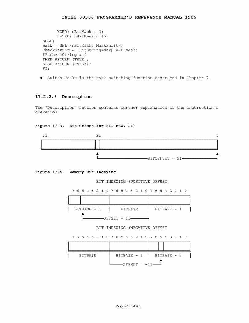
INTEL 80386 PROGRAMMER'S REFERENCE MANUAL 1986
Page 253 of 421
WORD: nBitMask ← 3; DWORD: nBitMask ← 15; ESAC; mask ← SHL (nBitMask, MaskShift); CheckString ← [BitStringAddr] AND mask; IF CheckString = 0 THEN RETURN (TRUE); ELSE RETURN (FALSE); FI;
● Switch-Tasks is the task switching function described in Chapter 7.
17.2.2.6 Description
The "Description" section contains further explanation of the instruction'soperation.
Figure 17-3. Bit Offset for BIT[EAX, 21]
31 21 0 ╔═════════════════════╦═╦═══════════════════════════════════════════════╗ ║ ║ ║ ║ ╚═════════════════════╩═╩═══════════════════════════════════════════════╝ ▲ ▲ └────────────────────BITOFFSET = 21──────────────┘
Figure 17-4. Memory Bit Indexing
BIT INDEXING (POSITIVE OFFSET)
7 6 5 4 3 2 1 0 7 6 5 4 3 2 1 0 7 6 5 4 3 2 1 0 ╔════╤═╤═════════╤═══════════════╤════════════════╗ ║ │ │ │ │ ║ ╚════╧═╧═════════╧═══════════════╪════════════════╝ │ BITBASE + 1 │ BITBASE │ BITBASE - 1 │ ▲ │ └────────OFFSET = 13───────┘
BIT INDEXING (NEGATIVE OFFSET)
7 6 5 4 3 2 1 0 7 6 5 4 3 2 1 0 7 6 5 4 3 2 1 0 ╔════════════════╤═══════════════╤═══╤═╤══════════╗ ║ │ │ │ │ ║ ╚════════════════╪═══════════════╧═══╧═╧══════════╝ │ BITBASE │ BITBASE - 1 │ BITBASE - 2 │ │ ▲ └─────OFFSET = -11───┘
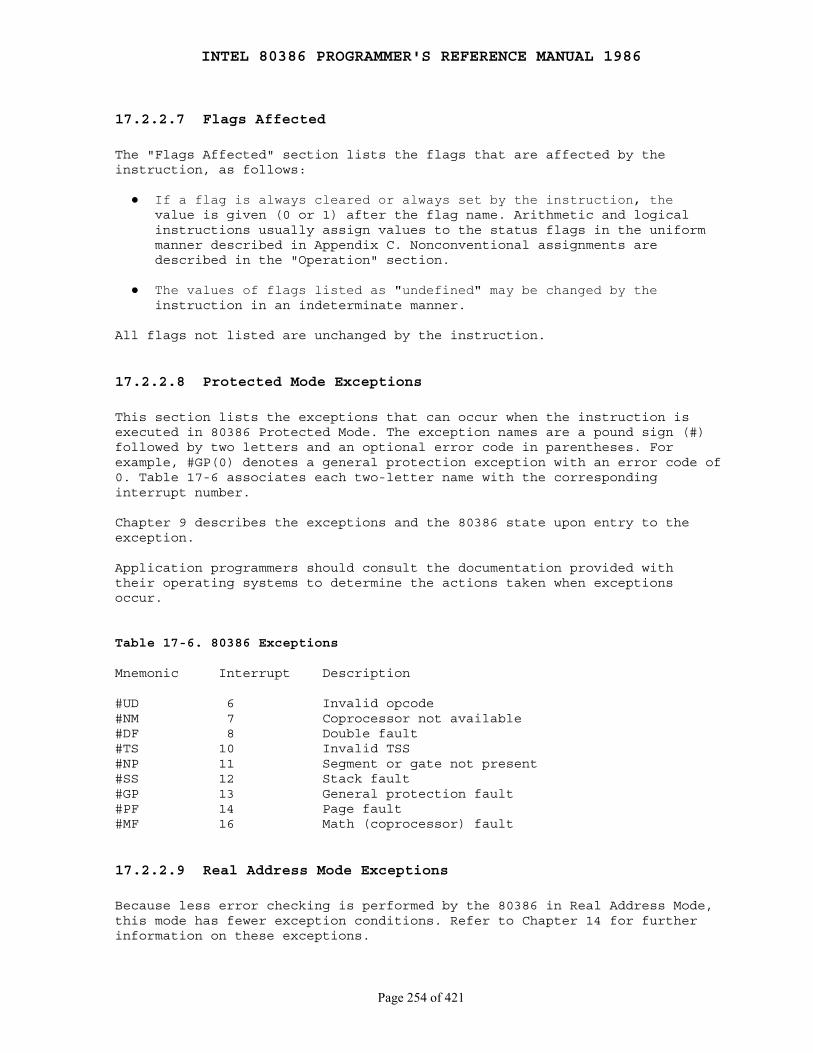
INTEL 80386 PROGRAMMER'S REFERENCE MANUAL 1986
Page 254 of 421
17.2.2.7 Flags Affected
The "Flags Affected" section lists the flags that are affected by theinstruction, as follows:
● If a flag is always cleared or always set by the instruction, the value is given (0 or 1) after the flag name. Arithmetic and logical instructions usually assign values to the status flags in the uniform manner described in Appendix C. Nonconventional assignments are described in the "Operation" section.
● The values of flags listed as "undefined" may be changed by the instruction in an indeterminate manner.
All flags not listed are unchanged by the instruction.
17.2.2.8 Protected Mode Exceptions
This section lists the exceptions that can occur when the instruction isexecuted in 80386 Protected Mode. The exception names are a pound sign (#)followed by two letters and an optional error code in parentheses. Forexample, #GP(0) denotes a general protection exception with an error code of0. Table 17-6 associates each two-letter name with the correspondinginterrupt number.
Chapter 9 describes the exceptions and the 80386 state upon entry to theexception.
Application programmers should consult the documentation provided withtheir operating systems to determine the actions taken when exceptionsoccur.
Table 17-6. 80386 Exceptions
Mnemonic Interrupt Description
#UD 6 Invalid opcode#NM 7 Coprocessor not available#DF 8 Double fault#TS 10 Invalid TSS#NP 11 Segment or gate not present#SS 12 Stack fault#GP 13 General protection fault#PF 14 Page fault#MF 16 Math (coprocessor) fault
17.2.2.9 Real Address Mode Exceptions
Because less error checking is performed by the 80386 in Real Address Mode,this mode has fewer exception conditions. Refer to Chapter 14 for furtherinformation on these exceptions.
INTEL 80386 PROGRAMMER'S REFERENCE MANUAL 1986
Page 255 of 421
17.2.2.10 Virtual-8086 Mode Exceptions
Virtual 8086 tasks provide the ability to simulate Virtual 8086 machines.Virtual 8086 Mode exceptions are similar to those for the 8086 processor,but there are some differences. Refer to Chapter 15 for details.
17.2.2.11 Instruction Set Detail
The instruction set is detailed as follows:
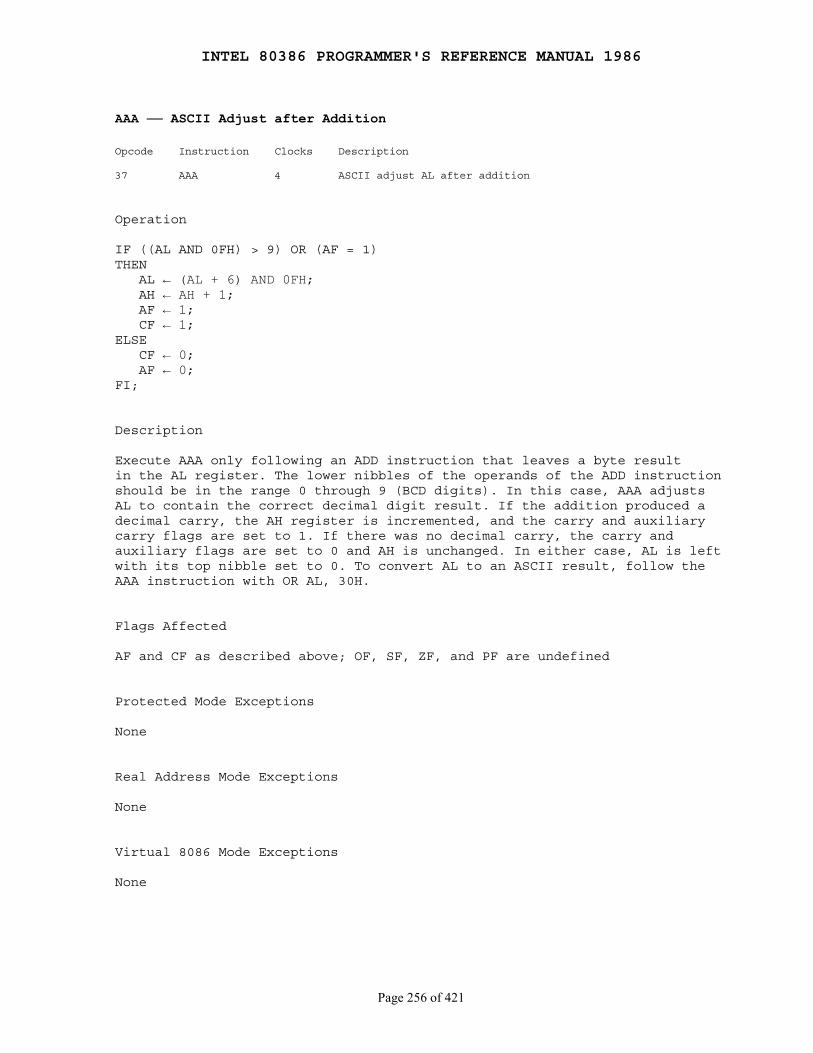
INTEL 80386 PROGRAMMER'S REFERENCE MANUAL 1986
Page 256 of 421
AAA ── ASCII Adjust after Addition
Opcode Instruction Clocks Description
37 AAA 4 ASCII adjust AL after addition
Operation
IF ((AL AND 0FH) > 9) OR (AF = 1)THEN AL ← (AL + 6) AND 0FH; AH ← AH + 1; AF ← 1; CF ← 1;ELSE CF ← 0; AF ← 0;FI;
Description
Execute AAA only following an ADD instruction that leaves a byte resultin the AL register. The lower nibbles of the operands of the ADD instructionshould be in the range 0 through 9 (BCD digits). In this case, AAA adjustsAL to contain the correct decimal digit result. If the addition produced adecimal carry, the AH register is incremented, and the carry and auxiliarycarry flags are set to 1. If there was no decimal carry, the carry andauxiliary flags are set to 0 and AH is unchanged. In either case, AL is leftwith its top nibble set to 0. To convert AL to an ASCII result, follow theAAA instruction with OR AL, 30H.
Flags Affected
AF and CF as described above; OF, SF, ZF, and PF are undefined
Protected Mode Exceptions
None
Real Address Mode Exceptions
None
Virtual 8086 Mode Exceptions
None
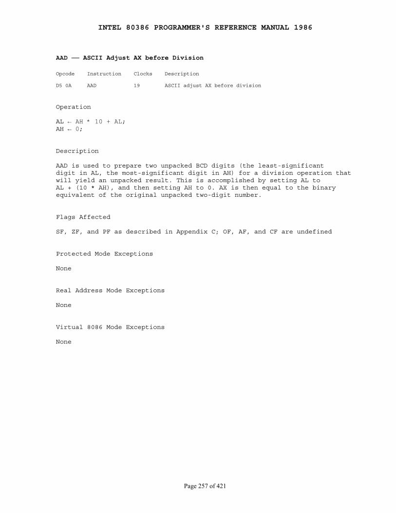
INTEL 80386 PROGRAMMER'S REFERENCE MANUAL 1986
Page 257 of 421
AAD ── ASCII Adjust AX before Division
Opcode Instruction Clocks Description
D5 0A AAD 19 ASCII adjust AX before division
Operation
AL ← AH * 10 + AL;AH ← 0;
Description
AAD is used to prepare two unpacked BCD digits (the least-significantdigit in AL, the most-significant digit in AH) for a division operation thatwill yield an unpacked result. This is accomplished by setting AL toAL + (10 * AH), and then setting AH to 0. AX is then equal to the binaryequivalent of the original unpacked two-digit number.
Flags Affected
SF, ZF, and PF as described in Appendix C; OF, AF, and CF are undefined
Protected Mode Exceptions
None
Real Address Mode Exceptions
None
Virtual 8086 Mode Exceptions
None

INTEL 80386 PROGRAMMER'S REFERENCE MANUAL 1986
Page 258 of 421
AAM ── ASCII Adjust AX after Multiply
Opcode Instruction Clocks Description
D4 0A AAM 17 ASCII adjust AX after multiply
Operation
AH ← AL / 10;AL ← AL MOD 10;
Description
Execute AAM only after executing a MUL instruction between two unpackedBCD digits that leaves the result in the AX register. Because the result isless than 100, it is contained entirely in the AL register. AAM unpacks theAL result by dividing AL by 10, leaving the quotient (most-significantdigit) in AH and the remainder (least-significant digit) in AL.
Flags Affected
SF, ZF, and PF as described in Appendix C; OF, AF, and CF are undefined
Protected Mode Exceptions
None
Real Address Mode Exceptions
None
Virtual 8086 Mode Exceptions
None
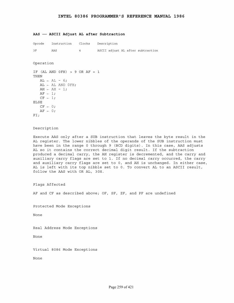
INTEL 80386 PROGRAMMER'S REFERENCE MANUAL 1986
Page 259 of 421
AAS ── ASCII Adjust AL after Subtraction
Opcode Instruction Clocks Description
3F AAS 4 ASCII adjust AL after subtraction
Operation
IF (AL AND 0FH) > 9 OR AF = 1THEN AL ← AL - 6; AL ← AL AND 0FH; AH ← AH - 1; AF ← 1; CF ← 1;ELSE CF ← 0; AF ← 0;FI;
Description
Execute AAS only after a SUB instruction that leaves the byte result in theAL register. The lower nibbles of the operands of the SUB instruction musthave been in the range 0 through 9 (BCD digits). In this case, AAS adjustsAL so it contains the correct decimal digit result. If the subtractionproduced a decimal carry, the AH register is decremented, and the carry andauxiliary carry flags are set to 1. If no decimal carry occurred, the carryand auxiliary carry flags are set to 0, and AH is unchanged. In either case,AL is left with its top nibble set to 0. To convert AL to an ASCII result,follow the AAS with OR AL, 30H.
Flags Affected
AF and CF as described above; OF, SF, ZF, and PF are undefined
Protected Mode Exceptions
None
Real Address Mode Exceptions
None
Virtual 8086 Mode Exceptions
None
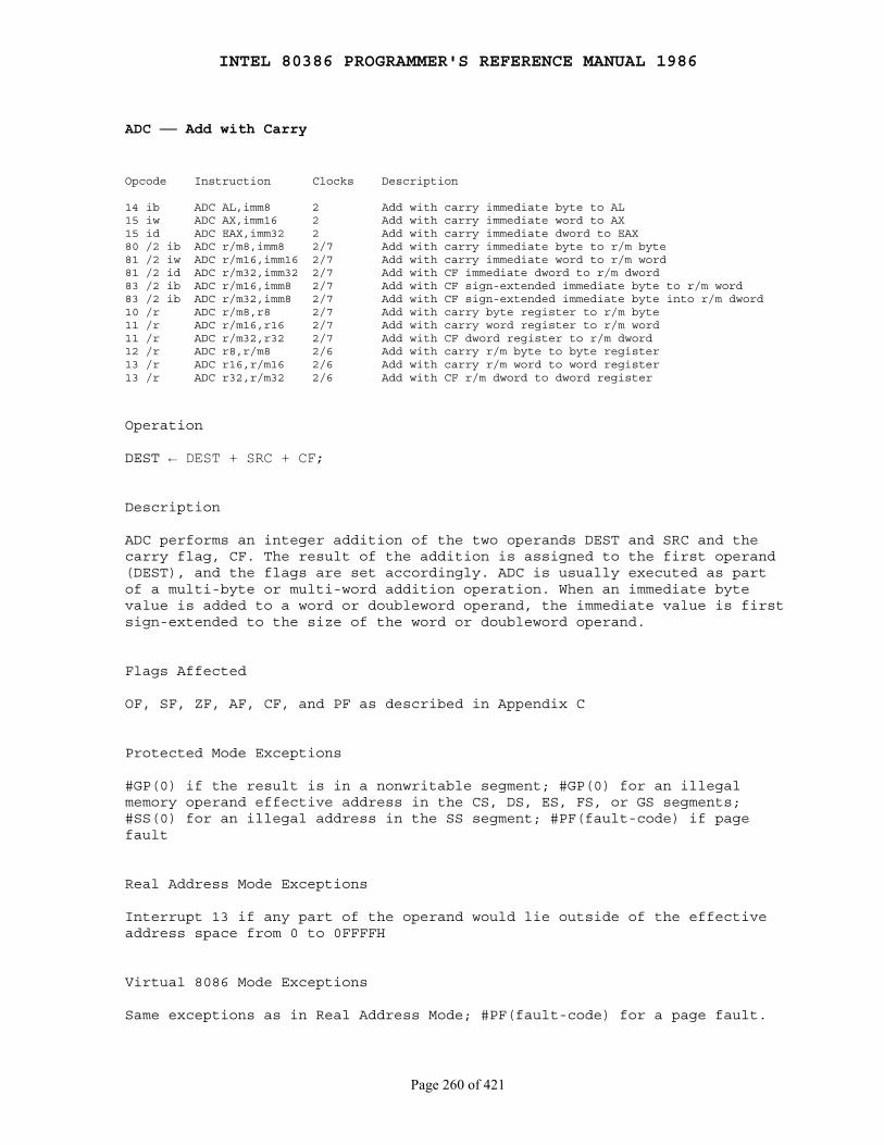
INTEL 80386 PROGRAMMER'S REFERENCE MANUAL 1986
Page 260 of 421
ADC ── Add with Carry
Opcode Instruction Clocks Description
14 ib ADC AL,imm8 2 Add with carry immediate byte to AL15 iw ADC AX,imm16 2 Add with carry immediate word to AX15 id ADC EAX,imm32 2 Add with carry immediate dword to EAX80 /2 ib ADC r/m8,imm8 2/7 Add with carry immediate byte to r/m byte81 /2 iw ADC r/m16,imm16 2/7 Add with carry immediate word to r/m word81 /2 id ADC r/m32,imm32 2/7 Add with CF immediate dword to r/m dword83 /2 ib ADC r/m16,imm8 2/7 Add with CF sign-extended immediate byte to r/m word83 /2 ib ADC r/m32,imm8 2/7 Add with CF sign-extended immediate byte into r/m dword10 /r ADC r/m8,r8 2/7 Add with carry byte register to r/m byte11 /r ADC r/m16,r16 2/7 Add with carry word register to r/m word11 /r ADC r/m32,r32 2/7 Add with CF dword register to r/m dword12 /r ADC r8,r/m8 2/6 Add with carry r/m byte to byte register13 /r ADC r16,r/m16 2/6 Add with carry r/m word to word register13 /r ADC r32,r/m32 2/6 Add with CF r/m dword to dword register
Operation
DEST ← DEST + SRC + CF;
Description
ADC performs an integer addition of the two operands DEST and SRC and thecarry flag, CF. The result of the addition is assigned to the first operand(DEST), and the flags are set accordingly. ADC is usually executed as partof a multi-byte or multi-word addition operation. When an immediate bytevalue is added to a word or doubleword operand, the immediate value is firstsign-extended to the size of the word or doubleword operand.
Flags Affected
OF, SF, ZF, AF, CF, and PF as described in Appendix C
Protected Mode Exceptions
#GP(0) if the result is in a nonwritable segment; #GP(0) for an illegalmemory operand effective address in the CS, DS, ES, FS, or GS segments;#SS(0) for an illegal address in the SS segment; #PF(fault-code) if pagefault
Real Address Mode Exceptions
Interrupt 13 if any part of the operand would lie outside of the effectiveaddress space from 0 to 0FFFFH
Virtual 8086 Mode Exceptions
Same exceptions as in Real Address Mode; #PF(fault-code) for a page fault.
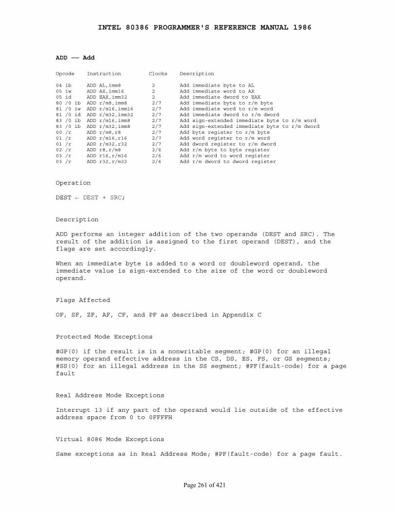
INTEL 80386 PROGRAMMER'S REFERENCE MANUAL 1986
Page 261 of 421
ADD ── Add
Opcode Instruction Clocks Description
04 ib ADD AL,imm8 2 Add immediate byte to AL05 iw ADD AX,imm16 2 Add immediate word to AX05 id ADD EAX,imm32 2 Add immediate dword to EAX80 /0 ib ADD r/m8,imm8 2/7 Add immediate byte to r/m byte81 /0 iw ADD r/m16,imm16 2/7 Add immediate word to r/m word81 /0 id ADD r/m32,imm32 2/7 Add immediate dword to r/m dword83 /0 ib ADD r/m16,imm8 2/7 Add sign-extended immediate byte to r/m word83 /0 ib ADD r/m32,imm8 2/7 Add sign-extended immediate byte to r/m dword00 /r ADD r/m8,r8 2/7 Add byte register to r/m byte01 /r ADD r/m16,r16 2/7 Add word register to r/m word01 /r ADD r/m32,r32 2/7 Add dword register to r/m dword02 /r ADD r8,r/m8 2/6 Add r/m byte to byte register03 /r ADD r16,r/m16 2/6 Add r/m word to word register03 /r ADD r32,r/m32 2/6 Add r/m dword to dword register
Operation
DEST ← DEST + SRC;
Description
ADD performs an integer addition of the two operands (DEST and SRC). Theresult of the addition is assigned to the first operand (DEST), and theflags are set accordingly.
When an immediate byte is added to a word or doubleword operand, theimmediate value is sign-extended to the size of the word or doublewordoperand.
Flags Affected
OF, SF, ZF, AF, CF, and PF as described in Appendix C
Protected Mode Exceptions
#GP(0) if the result is in a nonwritable segment; #GP(0) for an illegalmemory operand effective address in the CS, DS, ES, FS, or GS segments;#SS(0) for an illegal address in the SS segment; #PF(fault-code) for a pagefault
Real Address Mode Exceptions
Interrupt 13 if any part of the operand would lie outside of the effectiveaddress space from 0 to 0FFFFH
Virtual 8086 Mode Exceptions
Same exceptions as in Real Address Mode; #PF(fault-code) for a page fault.
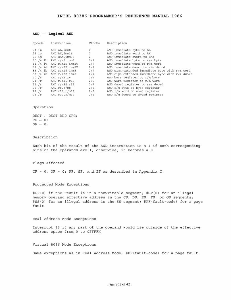
INTEL 80386 PROGRAMMER'S REFERENCE MANUAL 1986
Page 262 of 421
AND ── Logical AND
Opcode Instruction Clocks Description
24 ib AND AL,imm8 2 AND immediate byte to AL25 iw AND AX,imm16 2 AND immediate word to AX25 id AND EAX,imm32 2 AND immediate dword to EAX80 /4 ib AND r/m8,imm8 2/7 AND immediate byte to r/m byte81 /4 iw AND r/m16,imm16 2/7 AND immediate word to r/m word81 /4 id AND r/m32,imm32 2/7 AND immediate dword to r/m dword83 /4 ib AND r/m16,imm8 2/7 AND sign-extended immediate byte with r/m word83 /4 ib AND r/m32,imm8 2/7 AND sign-extended immediate byte with r/m dword20 /r AND r/m8,r8 2/7 AND byte register to r/m byte21 /r AND r/m16,r16 2/7 AND word register to r/m word21 /r AND r/m32,r32 2/7 AND dword register to r/m dword22 /r AND r8,r/m8 2/6 AND r/m byte to byte register23 /r AND r16,r/m16 2/6 AND r/m word to word register23 /r AND r32,r/m32 2/6 AND r/m dword to dword register
Operation
DEST ← DEST AND SRC;CF ← 0;OF ← 0;
Description
Each bit of the result of the AND instruction is a 1 if both correspondingbits of the operands are 1; otherwise, it becomes a 0.
Flags Affected
CF = 0, OF = 0; PF, SF, and ZF as described in Appendix C
Protected Mode Exceptions
#GP(0) if the result is in a nonwritable segment; #GP(0) for an illegalmemory operand effective address in the CS, DS, ES, FS, or GS segments;#SS(0) for an illegal address in the SS segment; #PF(fault-code) for a pagefault
Real Address Mode Exceptions
Interrupt 13 if any part of the operand would lie outside of the effectiveaddress space from 0 to 0FFFFH
Virtual 8086 Mode Exceptions
Same exceptions as in Real Address Mode; #PF(fault-code) for a page fault.
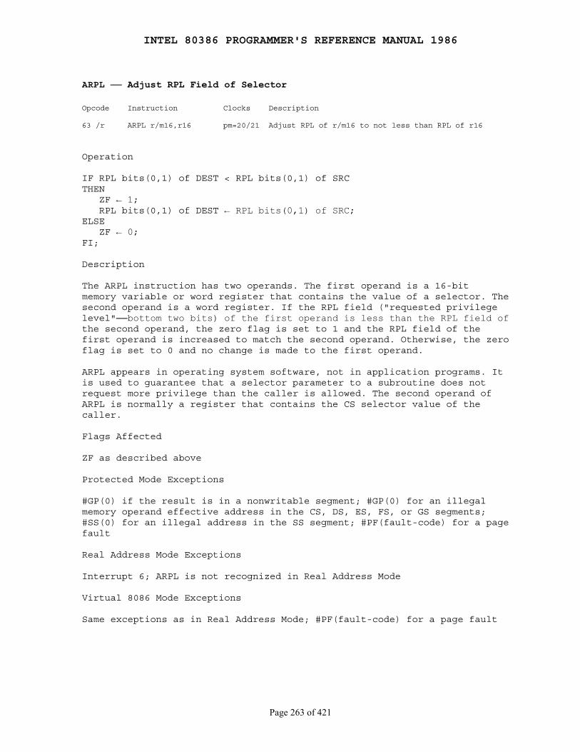
INTEL 80386 PROGRAMMER'S REFERENCE MANUAL 1986
Page 263 of 421
ARPL ── Adjust RPL Field of Selector
Opcode Instruction Clocks Description
63 /r ARPL r/m16,r16 pm=20/21 Adjust RPL of r/m16 to not less than RPL of r16
Operation
IF RPL bits(0,1) of DEST < RPL bits(0,1) of SRCTHEN ZF ← 1; RPL bits(0,1) of DEST ← RPL bits(0,1) of SRC;ELSE ZF ← 0;FI;
Description
The ARPL instruction has two operands. The first operand is a 16-bitmemory variable or word register that contains the value of a selector. Thesecond operand is a word register. If the RPL field ("requested privilegelevel"──bottom two bits) of the first operand is less than the RPL field ofthe second operand, the zero flag is set to 1 and the RPL field of thefirst operand is increased to match the second operand. Otherwise, the zeroflag is set to 0 and no change is made to the first operand.
ARPL appears in operating system software, not in application programs. Itis used to guarantee that a selector parameter to a subroutine does notrequest more privilege than the caller is allowed. The second operand ofARPL is normally a register that contains the CS selector value of thecaller.
Flags Affected
ZF as described above
Protected Mode Exceptions
#GP(0) if the result is in a nonwritable segment; #GP(0) for an illegalmemory operand effective address in the CS, DS, ES, FS, or GS segments;#SS(0) for an illegal address in the SS segment; #PF(fault-code) for a pagefault
Real Address Mode Exceptions
Interrupt 6; ARPL is not recognized in Real Address Mode
Virtual 8086 Mode Exceptions
Same exceptions as in Real Address Mode; #PF(fault-code) for a page fault
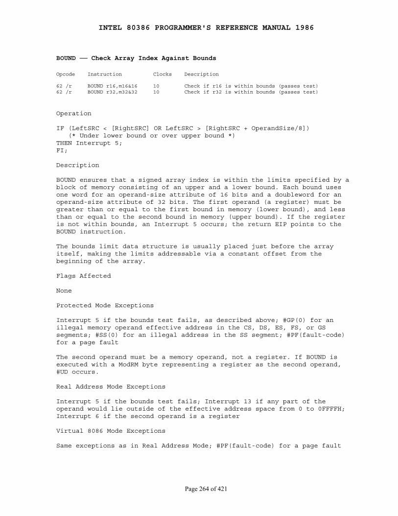
INTEL 80386 PROGRAMMER'S REFERENCE MANUAL 1986
Page 264 of 421
BOUND ── Check Array Index Against Bounds
Opcode Instruction Clocks Description
62 /r BOUND r16,m16&16 10 Check if r16 is within bounds (passes test)62 /r BOUND r32,m32&32 10 Check if r32 is within bounds (passes test)
Operation
IF (LeftSRC < [RightSRC] OR LeftSRC > [RightSRC + OperandSize/8]) (* Under lower bound or over upper bound *)THEN Interrupt 5;FI;
Description
BOUND ensures that a signed array index is within the limits specified by ablock of memory consisting of an upper and a lower bound. Each bound usesone word for an operand-size attribute of 16 bits and a doubleword for anoperand-size attribute of 32 bits. The first operand (a register) must begreater than or equal to the first bound in memory (lower bound), and lessthan or equal to the second bound in memory (upper bound). If the registeris not within bounds, an Interrupt 5 occurs; the return EIP points to theBOUND instruction.
The bounds limit data structure is usually placed just before the arrayitself, making the limits addressable via a constant offset from thebeginning of the array.
Flags Affected
None
Protected Mode Exceptions
Interrupt 5 if the bounds test fails, as described above; #GP(0) for anillegal memory operand effective address in the CS, DS, ES, FS, or GSsegments; #SS(0) for an illegal address in the SS segment; #PF(fault-code)for a page fault
The second operand must be a memory operand, not a register. If BOUND isexecuted with a ModRM byte representing a register as the second operand,#UD occurs.
Real Address Mode Exceptions
Interrupt 5 if the bounds test fails; Interrupt 13 if any part of theoperand would lie outside of the effective address space from 0 to 0FFFFH;Interrupt 6 if the second operand is a register
Virtual 8086 Mode Exceptions
Same exceptions as in Real Address Mode; #PF(fault-code) for a page fault

INTEL 80386 PROGRAMMER'S REFERENCE MANUAL 1986
Page 265 of 421
BSF ── Bit Scan Forward
Opcode Instruction Clocks Description
0F BC BSF r16,r/m16 10+3n Bit scan forward on r/m word0F BC BSF r32,r/m32 10+3n Bit scan forward on r/m dword
Operation
IF r/m = 0THEN ZF ← 1; register ← UNDEFINED;ELSE temp ← 0; ZF ← 0; WHILE BIT[r/m, temp = 0] DO temp ← temp + 1; register ← temp; OD;FI;
Description
BSF scans the bits in the second word or doubleword operand starting withbit 0. The ZF flag is cleared if the bits are all 0; otherwise, the ZF flagis set and the destination register is loaded with the bit index of thefirst set bit.
Flags Affected
ZF as described above
Protected Mode Exceptions
#GP(0) for an illegal memory operand effective address in the CS, DS, ES,FS, or GS segments; #SS(0) for an illegal address in the SS segment;#PF(fault-code) for a page fault
Real Address Mode Exceptions
Interrupt 13 if any part of the operand would lie outside of the effectiveaddress space from 0 to 0FFFFH
Virtual 8086 Mode Exceptions
Same exceptions as in Real Address Mode; #PF(fault-code) for a page fault.
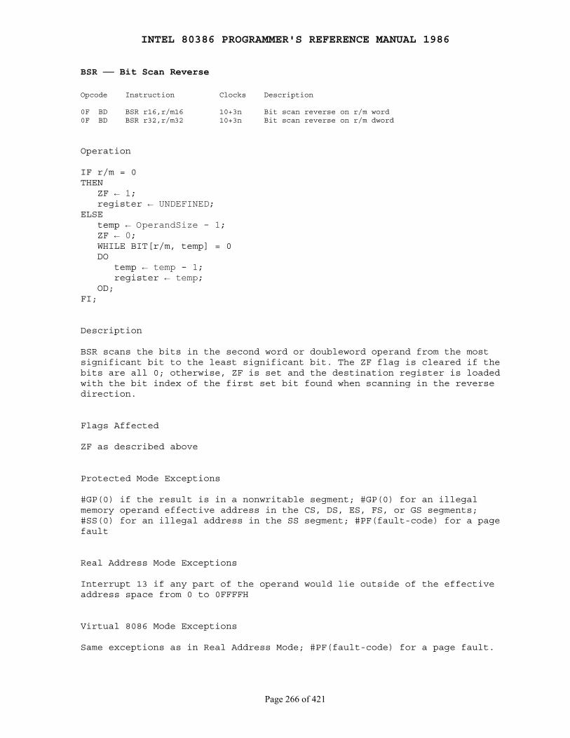
INTEL 80386 PROGRAMMER'S REFERENCE MANUAL 1986
Page 266 of 421
BSR ── Bit Scan Reverse
Opcode Instruction Clocks Description
0F BD BSR r16,r/m16 10+3n Bit scan reverse on r/m word0F BD BSR r32,r/m32 10+3n Bit scan reverse on r/m dword
Operation
IF r/m = 0THEN ZF ← 1; register ← UNDEFINED;ELSE temp ← OperandSize - 1; ZF ← 0; WHILE BIT[r/m, temp] = 0 DO temp ← temp - 1; register ← temp; OD;FI;
Description
BSR scans the bits in the second word or doubleword operand from the mostsignificant bit to the least significant bit. The ZF flag is cleared if thebits are all 0; otherwise, ZF is set and the destination register is loadedwith the bit index of the first set bit found when scanning in the reversedirection.
Flags Affected
ZF as described above
Protected Mode Exceptions
#GP(0) if the result is in a nonwritable segment; #GP(0) for an illegalmemory operand effective address in the CS, DS, ES, FS, or GS segments;#SS(0) for an illegal address in the SS segment; #PF(fault-code) for a pagefault
Real Address Mode Exceptions
Interrupt 13 if any part of the operand would lie outside of the effectiveaddress space from 0 to 0FFFFH
Virtual 8086 Mode Exceptions
Same exceptions as in Real Address Mode; #PF(fault-code) for a page fault.
INTEL 80386 PROGRAMMER'S REFERENCE MANUAL 1986
Page 267 of 421
BT ── Bit Test
Opcode Instruction Clocks Description
0F A3 BT r/m16,r16 3/12 Save bit in carry flag0F A3 BT r/m32,r32 3/12 Save bit in carry flag0F BA /4 ib BT r/m16,imm8 3/6 Save bit in carry flag0F BA /4 ib BT r/m32,imm8 3/6 Save bit in carry flag
Operation
CF ← BIT[LeftSRC, RightSRC];
Description
BT saves the value of the bit indicated by the base (first operand) and thebit offset (second operand) into the carry flag.
Flags Affected
CF as described above
Protected Mode Exceptions
#GP(0) for an illegal memory operand effective address in the CS, DS, ES,FS, or GS segments; #SS(0) for an illegal address in the SS segment;#PF(fault-code) for a page fault
Real Address Mode Exceptions
Interrupt 13 if any part of the operand would lie outside of the effectiveaddress space from 0 to 0FFFFH
Virtual 8086 Mode Exceptions
Same exceptions as in Real Address Mode; #PF(fault-code) for a page fault
Notes
The index of the selected bit can be given by the immediate constant in theinstruction or by a value in a general register. Only an 8-bit immediatevalue is used in the instruction. This operand is taken modulo 32, so therange of immediate bit offsets is 0..31. This allows any bit within aregister to be selected. For memory bit strings, this immediate field givesonly the bit offset within a word or doubleword. Immediate bit offsetslarger than 31 are supported by using the immediate bit offset field incombination with the displacement field of the memory operand. The low-order3 to 5 bits of the immediate bit offset are stored in the immediate bitoffset field, and the high-order 27 to 29 bits are shifted and combined withthe byte displacement in the addressing mode.
INTEL 80386 PROGRAMMER'S REFERENCE MANUAL 1986
Page 268 of 421
When accessing a bit in memory, the 80386 may access four bytes startingfrom the memory address given by:
Effective Address + (4 * (BitOffset DIV 32))
for a 32-bit operand size, or two bytes starting from the memory addressgiven by:
Effective Address + (2 * (BitOffset DIV 16))
for a 16-bit operand size. It may do so even when only a single byte needsto be accessed in order to reach the given bit. You must therefore avoidreferencing areas of memory close to address space holes. In particular,avoid references to memory-mapped I/O registers. Instead, use the MOVinstructions to load from or store to these addresses, and use the registerform of these instructions to manipulate the data.
INTEL 80386 PROGRAMMER'S REFERENCE MANUAL 1986
Page 269 of 421
BTC ── Bit Test and Complement
Opcode Instruction Clocks Description
0F BB BTC r/m16,r16 6/13 Save bit in carry flag and complement0F BB BTC r/m32,r32 6/13 Save bit in carry flag and complement0F BA /7 ib BTC r/m16,imm8 6/8 Save bit in carry flag and complement0F BA /7 ib BTC r/m32,imm8 6/8 Save bit in carry flag and complement
Operation
CF ← BIT[LeftSRC, RightSRC];BIT[LeftSRC, RightSRC] ← NOT BIT[LeftSRC, RightSRC];
Description
BTC saves the value of the bit indicated by the base (first operand) and thebit offset (second operand) into the carry flag and then complements thebit.
Flags Affected
CF as described above
Protected Mode Exceptions
#GP(0) if the result is in a nonwritable segment; #GP(0) for an illegalmemory operand effective address in the CS, DS, ES, FS, or GS segments;#SS(0) for an illegal address in the SS segment; #PF(fault-code) for a pagefault
Real Address Mode Exceptions
Interrupt 13 if any part of the operand would lie outside of the effectiveaddress space from 0 to 0FFFFH
Virtual 8086 Mode Exceptions
Same exceptions as in Real Address Mode; #PF(fault-code) for a page fault
Notes
The index of the selected bit can be given by the immediate constant in theinstruction or by a value in a general register. Only an 8-bit immediatevalue is used in the instruction. This operand is taken modulo 32, so therange of immediate bit offsets is 0..31. This allows any bit within aregister to be selected. For memory bit strings, this immediate field givesonly the bit offset within a word or doubleword. Immediate bit offsetslarger than 31 are supported by using the immediate bit offset field in
INTEL 80386 PROGRAMMER'S REFERENCE MANUAL 1986
Page 270 of 421
combination with the displacement field of the memory operand. The low-order3 to 5 bits of the immediate bit offset are stored in the immediate bitoffset field, and the high-order 27 to 29 bits are shifted and combined withthe byte displacement in the addressing mode.
When accessing a bit in memory, the 80386 may access four bytes startingfrom the memory address given by:
Effective Address + (4 * (BitOffset DIV 32))
for a 32-bit operand size, or two bytes starting from the memory addressgiven by:
Effective Address + (2 * (BitOffset DIV 16))
for a 16-bit operand size. It may do so even when only a single byte needsto be accessed in order to reach the given bit. You must therefore avoidreferencing areas of memory close to address space holes. In particular,avoid references to memory-mapped I/O registers. Instead, use the MOVinstructions to load from or store to these addresses, and use the registerform of these instructions to manipulate the data.
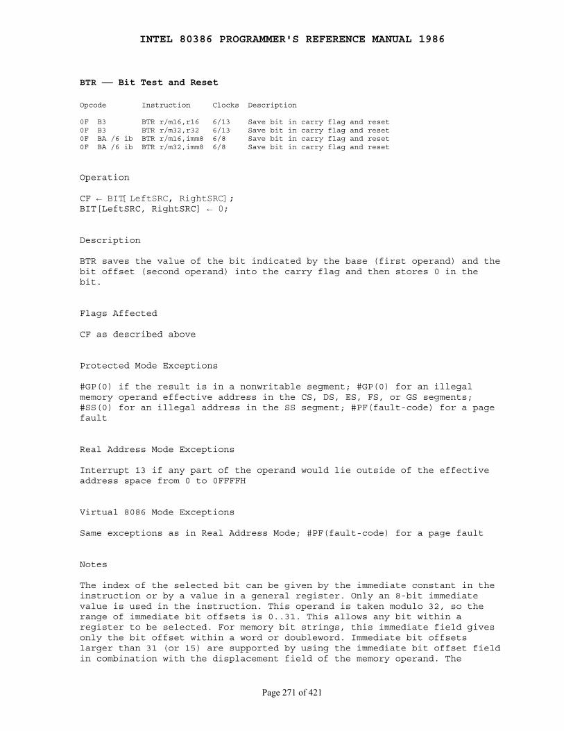
INTEL 80386 PROGRAMMER'S REFERENCE MANUAL 1986
Page 271 of 421
BTR ── Bit Test and Reset
Opcode Instruction Clocks Description
0F B3 BTR r/m16,r16 6/13 Save bit in carry flag and reset0F B3 BTR r/m32,r32 6/13 Save bit in carry flag and reset0F BA /6 ib BTR r/m16,imm8 6/8 Save bit in carry flag and reset0F BA /6 ib BTR r/m32,imm8 6/8 Save bit in carry flag and reset
Operation
CF ← BIT[LeftSRC, RightSRC];BIT[LeftSRC, RightSRC] ← 0;
Description
BTR saves the value of the bit indicated by the base (first operand) and thebit offset (second operand) into the carry flag and then stores 0 in thebit.
Flags Affected
CF as described above
Protected Mode Exceptions
#GP(0) if the result is in a nonwritable segment; #GP(0) for an illegalmemory operand effective address in the CS, DS, ES, FS, or GS segments;#SS(0) for an illegal address in the SS segment; #PF(fault-code) for a pagefault
Real Address Mode Exceptions
Interrupt 13 if any part of the operand would lie outside of the effectiveaddress space from 0 to 0FFFFH
Virtual 8086 Mode Exceptions
Same exceptions as in Real Address Mode; #PF(fault-code) for a page fault
Notes
The index of the selected bit can be given by the immediate constant in theinstruction or by a value in a general register. Only an 8-bit immediatevalue is used in the instruction. This operand is taken modulo 32, so therange of immediate bit offsets is 0..31. This allows any bit within aregister to be selected. For memory bit strings, this immediate field givesonly the bit offset within a word or doubleword. Immediate bit offsetslarger than 31 (or 15) are supported by using the immediate bit offset fieldin combination with the displacement field of the memory operand. The

INTEL 80386 PROGRAMMER'S REFERENCE MANUAL 1986
Page 272 of 421
low-order 3 to 5 bits of the immediate bit offset are stored in theimmediate bit offset field, and the high-order 27 to 29 bits are shifted andcombined with the byte displacement in the addressing mode.
When accessing a bit in memory, the 80386 may access four bytes startingfrom the memory address given by:
Effective Address + 4 * (BitOffset DIV 32)
for a 32-bit operand size, or two bytes starting from the memory addressgiven by:
Effective Address + 2 * (BitOffset DIV 16)
for a 16-bit operand size. It may do so even when only a single byte needsto be accessed in order to reach the given bit. You must therefore avoidreferencing areas of memory close to address space holes. In particular,avoid references to memory-mapped I/O registers. Instead, use the MOVinstructions to load from or store to these addresses, and use the registerform of these instructions to manipulate the data.
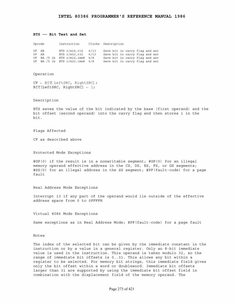
INTEL 80386 PROGRAMMER'S REFERENCE MANUAL 1986
Page 273 of 421
BTS ── Bit Test and Set
Opcode Instruction Clocks Description
0F AB BTS r/m16,r16 6/13 Save bit in carry flag and set0F AB BTS r/m32,r32 6/13 Save bit in carry flag and set0F BA /5 ib BTS r/m16,imm8 6/8 Save bit in carry flag and set0F BA /5 ib BTS r/m32,imm8 6/8 Save bit in carry flag and set
Operation
CF ← BIT[LeftSRC, RightSRC];BIT[LeftSRC, RightSRC] ← 1;
Description
BTS saves the value of the bit indicated by the base (first operand) and thebit offset (second operand) into the carry flag and then stores 1 in thebit.
Flags Affected
CF as described above
Protected Mode Exceptions
#GP(0) if the result is in a nonwritable segment; #GP(0) for an illegalmemory operand effective address in the CS, DS, ES, FS, or GS segments;#SS(0) for an illegal address in the SS segment; #PF(fault-code) for a pagefault
Real Address Mode Exceptions
Interrupt 13 if any part of the operand would lie outside of the effectiveaddress space from 0 to 0FFFFH
Virtual 8086 Mode Exceptions
Same exceptions as in Real Address Mode; #PF(fault-code) for a page fault
Notes
The index of the selected bit can be given by the immediate constant in theinstruction or by a value in a general register. Only an 8-bit immediatevalue is used in the instruction. This operand is taken modulo 32, so therange of immediate bit offsets is 0..31. This allows any bit within aregister to be selected. For memory bit strings, this immediate field givesonly the bit offset within a word or doubleword. Immediate bit offsetslarger than 31 are supported by using the immediate bit offset field incombination with the displacement field of the memory operand. The
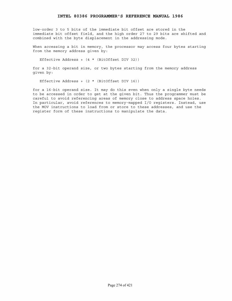
INTEL 80386 PROGRAMMER'S REFERENCE MANUAL 1986
Page 274 of 421
low-order 3 to 5 bits of the immediate bit offset are stored in theimmediate bit offset field, and the high order 27 to 29 bits are shifted andcombined with the byte displacement in the addressing mode.
When accessing a bit in memory, the processor may access four bytes startingfrom the memory address given by:
Effective Address + (4 * (BitOffset DIV 32))
for a 32-bit operand size, or two bytes starting from the memory addressgiven by:
Effective Address + (2 * (BitOffset DIV 16))
for a 16-bit operand size. It may do this even when only a single byte needsto be accessed in order to get at the given bit. Thus the programmer must becareful to avoid referencing areas of memory close to address space holes.In particular, avoid references to memory-mapped I/O registers. Instead, usethe MOV instructions to load from or store to these addresses, and use theregister form of these instructions to manipulate the data.
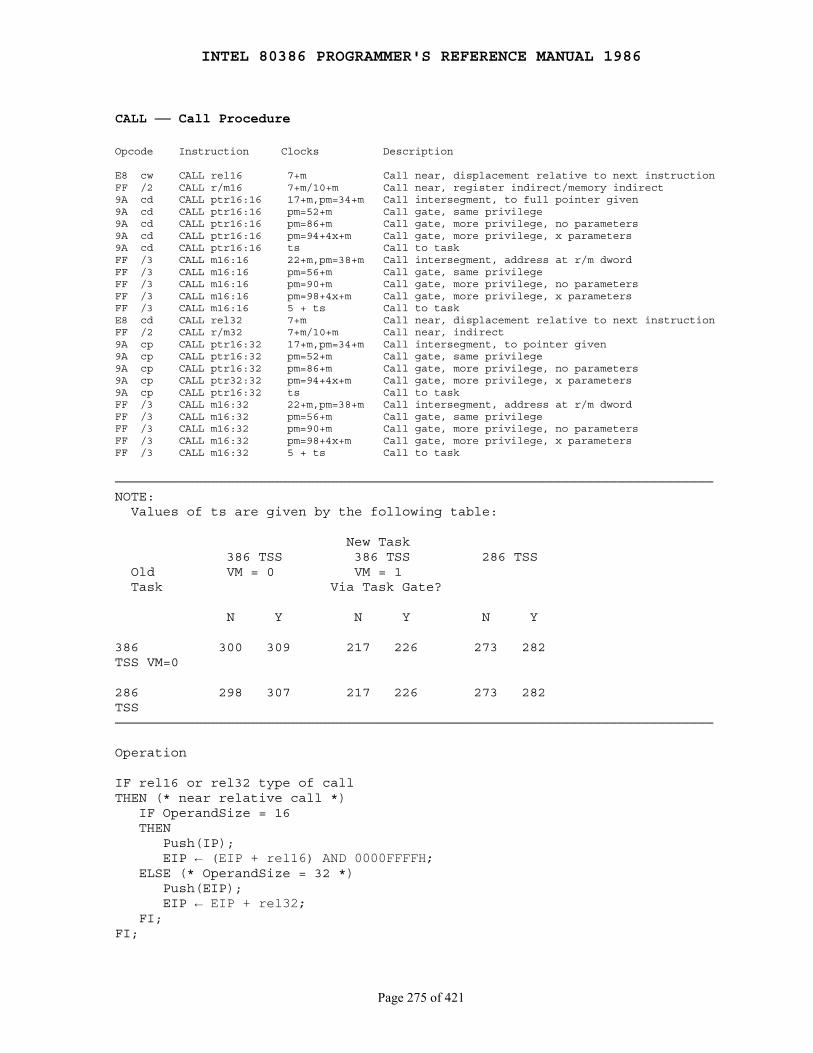
INTEL 80386 PROGRAMMER'S REFERENCE MANUAL 1986
Page 275 of 421
CALL ── Call Procedure
Opcode Instruction Clocks Description
E8 cw CALL rel16 7+m Call near, displacement relative to next instructionFF /2 CALL r/m16 7+m/10+m Call near, register indirect/memory indirect9A cd CALL ptr16:16 17+m,pm=34+m Call intersegment, to full pointer given9A cd CALL ptr16:16 pm=52+m Call gate, same privilege9A cd CALL ptr16:16 pm=86+m Call gate, more privilege, no parameters9A cd CALL ptr16:16 pm=94+4x+m Call gate, more privilege, x parameters9A cd CALL ptr16:16 ts Call to taskFF /3 CALL m16:16 22+m,pm=38+m Call intersegment, address at r/m dwordFF /3 CALL m16:16 pm=56+m Call gate, same privilegeFF /3 CALL m16:16 pm=90+m Call gate, more privilege, no parametersFF /3 CALL m16:16 pm=98+4x+m Call gate, more privilege, x parametersFF /3 CALL m16:16 5 + ts Call to taskE8 cd CALL rel32 7+m Call near, displacement relative to next instructionFF /2 CALL r/m32 7+m/10+m Call near, indirect9A cp CALL ptr16:32 17+m,pm=34+m Call intersegment, to pointer given9A cp CALL ptr16:32 pm=52+m Call gate, same privilege9A cp CALL ptr16:32 pm=86+m Call gate, more privilege, no parameters9A cp CALL ptr32:32 pm=94+4x+m Call gate, more privilege, x parameters9A cp CALL ptr16:32 ts Call to taskFF /3 CALL m16:32 22+m,pm=38+m Call intersegment, address at r/m dwordFF /3 CALL m16:32 pm=56+m Call gate, same privilegeFF /3 CALL m16:32 pm=90+m Call gate, more privilege, no parametersFF /3 CALL m16:32 pm=98+4x+m Call gate, more privilege, x parametersFF /3 CALL m16:32 5 + ts Call to task
───────────────────────────────────────────────────────────────────────────NOTE: Values of ts are given by the following table:
New Task 386 TSS 386 TSS 286 TSS Old VM = 0 VM = 1 Task Via Task Gate?
N Y N Y N Y
386 300 309 217 226 273 282TSS VM=0
286 298 307 217 226 273 282TSS───────────────────────────────────────────────────────────────────────────
Operation
IF rel16 or rel32 type of callTHEN (* near relative call *) IF OperandSize = 16 THEN Push(IP); EIP ← (EIP + rel16) AND 0000FFFFH; ELSE (* OperandSize = 32 *) Push(EIP); EIP ← EIP + rel32; FI;FI;

INTEL 80386 PROGRAMMER'S REFERENCE MANUAL 1986
Page 276 of 421
IF r/m16 or r/m32 type of callTHEN (* near absolute call *) IF OperandSize = 16 THEN Push(IP); EIP ← [r/m16] AND 0000FFFFH; ELSE (* OperandSize = 32 *) Push(EIP); EIP ← [r/m32]; FI;FI;
IF (PE = 0 OR (PE = 1 AND VM = 1))(* real mode or virtual 8086 mode *) AND instruction = far CALL (* i.e., operand type is m16:16, m16:32, ptr16:16, ptr16:32 *)THEN IF OperandSize = 16 THEN Push(CS); Push(IP); (* address of next instruction; 16 bits *) ELSE Push(CS); (* padded with 16 high-order bits *) Push(EIP); (* address of next instruction; 32 bits *) FI; IF operand type is m16:16 or m16:32 THEN (* indirect far call *) IF OperandSize = 16 THEN CS:IP ← [m16:16]; EIP ← EIP AND 0000FFFFH; (* clear upper 16 bits *) ELSE (* OperandSize = 32 *) CS:EIP ← [m16:32]; FI; FI; IF operand type is ptr16:16 or ptr16:32 THEN (* direct far call *) IF OperandSize = 16 THEN CS:IP ← ptr16:16; EIP ← EIP AND 0000FFFFH; (* clear upper 16 bits *) ELSE (* OperandSize = 32 *) CS:EIP ← ptr16:32; FI; FI;FI;
IF (PE = 1 AND VM = 0) (* Protected mode, not V86 mode *) AND instruction = far CALLTHEN If indirect, then check access of EA doubleword; #GP(0) if limit violation; New CS selector must not be null else #GP(0); Check that new CS selector index is within its descriptor table limits; else #GP(new CS selector); Examine AR byte of selected descriptor for various legal values; depending on value:
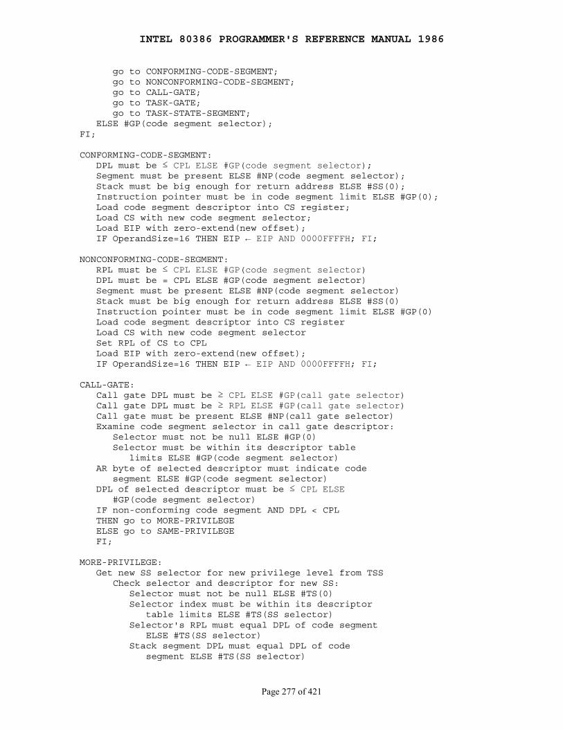
INTEL 80386 PROGRAMMER'S REFERENCE MANUAL 1986
Page 277 of 421
go to CONFORMING-CODE-SEGMENT; go to NONCONFORMING-CODE-SEGMENT; go to CALL-GATE; go to TASK-GATE; go to TASK-STATE-SEGMENT; ELSE #GP(code segment selector);FI;
CONFORMING-CODE-SEGMENT: DPL must be ≤ CPL ELSE #GP(code segment selector); Segment must be present ELSE #NP(code segment selector); Stack must be big enough for return address ELSE #SS(0); Instruction pointer must be in code segment limit ELSE #GP(0); Load code segment descriptor into CS register; Load CS with new code segment selector; Load EIP with zero-extend(new offset); IF OperandSize=16 THEN EIP ← EIP AND 0000FFFFH; FI;
NONCONFORMING-CODE-SEGMENT: RPL must be ≤ CPL ELSE #GP(code segment selector) DPL must be = CPL ELSE #GP(code segment selector) Segment must be present ELSE #NP(code segment selector) Stack must be big enough for return address ELSE #SS(0) Instruction pointer must be in code segment limit ELSE #GP(0) Load code segment descriptor into CS register Load CS with new code segment selector Set RPL of CS to CPL Load EIP with zero-extend(new offset); IF OperandSize=16 THEN EIP ← EIP AND 0000FFFFH; FI;
CALL-GATE: Call gate DPL must be ≥ CPL ELSE #GP(call gate selector) Call gate DPL must be ≥ RPL ELSE #GP(call gate selector) Call gate must be present ELSE #NP(call gate selector) Examine code segment selector in call gate descriptor: Selector must not be null ELSE #GP(0) Selector must be within its descriptor table limits ELSE #GP(code segment selector) AR byte of selected descriptor must indicate code segment ELSE #GP(code segment selector) DPL of selected descriptor must be ≤ CPL ELSE #GP(code segment selector) IF non-conforming code segment AND DPL < CPL THEN go to MORE-PRIVILEGE ELSE go to SAME-PRIVILEGE FI;
MORE-PRIVILEGE: Get new SS selector for new privilege level from TSS Check selector and descriptor for new SS: Selector must not be null ELSE #TS(0) Selector index must be within its descriptor table limits ELSE #TS(SS selector) Selector's RPL must equal DPL of code segment ELSE #TS(SS selector) Stack segment DPL must equal DPL of code segment ELSE #TS(SS selector)
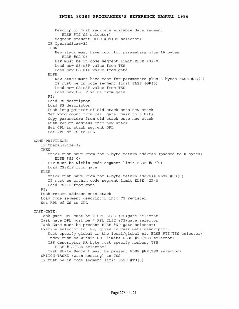
INTEL 80386 PROGRAMMER'S REFERENCE MANUAL 1986
Page 278 of 421
Descriptor must indicate writable data segment ELSE #TS(SS selector) Segment present ELSE #SS(SS selector) IF OperandSize=32 THEN New stack must have room for parameters plus 16 bytes ELSE #SS(0) EIP must be in code segment limit ELSE #GP(0) Load new SS:eSP value from TSS Load new CS:EIP value from gate ELSE New stack must have room for parameters plus 8 bytes ELSE #SS(0) IP must be in code segment limit ELSE #GP(0) Load new SS:eSP value from TSS Load new CS:IP value from gate FI; Load CS descriptor Load SS descriptor Push long pointer of old stack onto new stack Get word count from call gate, mask to 5 bits Copy parameters from old stack onto new stack Push return address onto new stack Set CPL to stack segment DPL Set RPL of CS to CPL
SAME-PRIVILEGE: IF OperandSize=32 THEN Stack must have room for 6-byte return address (padded to 8 bytes) ELSE #SS(0) EIP must be within code segment limit ELSE #GP(0) Load CS:EIP from gate ELSE Stack must have room for 4-byte return address ELSE #SS(0) IP must be within code segment limit ELSE #GP(0) Load CS:IP from gate FI; Push return address onto stack Load code segment descriptor into CS register Set RPL of CS to CPL
TASK-GATE: Task gate DPL must be ≥ CPL ELSE #TS(gate selector) Task gate DPL must be ≥ RPL ELSE #TS(gate selector) Task Gate must be present ELSE #NP(gate selector) Examine selector to TSS, given in Task Gate descriptor: Must specify global in the local/global bit ELSE #TS(TSS selector) Index must be within GDT limits ELSE #TS(TSS selector) TSS descriptor AR byte must specify nonbusy TSS ELSE #TS(TSS selector) Task State Segment must be present ELSE #NP(TSS selector) SWITCH-TASKS (with nesting) to TSS IP must be in code segment limit ELSE #TS(0)

INTEL 80386 PROGRAMMER'S REFERENCE MANUAL 1986
Page 279 of 421
TASK-STATE-SEGMENT: TSS DPL must be ≥ CPL else #TS(TSS selector) TSS DPL must be ≥ RPL ELSE #TS(TSS selector) TSS descriptor AR byte must specify available TSS ELSE #TS(TSS selector) Task State Segment must be present ELSE #NP(TSS selector) SWITCH-TASKS (with nesting) to TSS IP must be in code segment limit ELSE #TS(0)
Description
The CALL instruction causes the procedure named in the operand to beexecuted. When the procedure is complete (a return instruction is executedwithin the procedure), execution continues at the instruction that followsthe CALL instruction.
The action of the different forms of the instruction are described below.
Near calls are those with destinations of type r/m16, r/m32, rel16, rel32;changing or saving the segment register value is not necessary. The CALLrel16 and CALL rel32 forms add a signed offset to the address of theinstruction following CALL to determine the destination. The rel16 form isused when the instruction's operand-size attribute is 16 bits; rel32 is usedwhen the operand-size attribute is 32 bits. The result is stored in the32-bit EIP register. With rel16, the upper 16 bits of EIP are cleared,resulting in an offset whose value does not exceed 16 bits. CALL r/m16 andCALL r/m32 specify a register or memory location from which the absolutesegment offset is fetched. The offset fetched from r/m is 32 bits for anoperand-size attribute of 32 (r/m32), or 16 bits for an operand-size of 16(r/m16). The offset of the instruction following CALL is pushed onto thestack. It will be popped by a near RET instruction within the procedure. TheCS register is not changed by this form of CALL.
The far calls, CALL ptr16:16 and CALL ptr16:32, use a four-byte or six-byteoperand as a long pointer to the procedure called. The CALL m16:16 andm16:32 forms fetch the long pointer from the memory locationspecified (indirection). In Real Address Mode or Virtual 8086 Mode, the longpointer provides 16 bits for the CS register and 16 or 32 bits for the EIPregister (depending on the operand-size attribute). These forms of theinstruction push both CS and IP or EIP as a return address.
In Protected Mode, both long pointer forms consult the AR byte in thedescriptor indexed by the selector part of the long pointer. Depending onthe value of the AR byte, the call will perform one of the following typesof control transfers:
● A far call to the same protection level ● An inter-protection level far call ● A task switch
For more information on Protected Mode control transfers, refer toChapter 6 and Chapter 7.
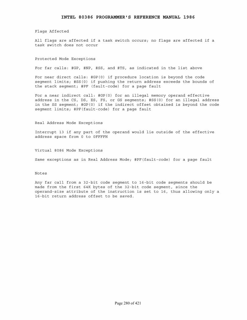
INTEL 80386 PROGRAMMER'S REFERENCE MANUAL 1986
Page 280 of 421
Flags Affected
All flags are affected if a task switch occurs; no flags are affected if atask switch does not occur
Protected Mode Exceptions
For far calls: #GP, #NP, #SS, and #TS, as indicated in the list above
For near direct calls: #GP(0) if procedure location is beyond the codesegment limits; #SS(0) if pushing the return address exceeds the bounds ofthe stack segment; #PF (fault-code) for a page fault
For a near indirect call: #GP(0) for an illegal memory operand effectiveaddress in the CS, DS, ES, FS, or GS segments; #SS(0) for an illegal addressin the SS segment; #GP(0) if the indirect offset obtained is beyond the codesegment limits; #PF(fault-code) for a page fault
Real Address Mode Exceptions
Interrupt 13 if any part of the operand would lie outside of the effectiveaddress space from 0 to 0FFFFH
Virtual 8086 Mode Exceptions
Same exceptions as in Real Address Mode; #PF(fault-code) for a page fault
Notes
Any far call from a 32-bit code segment to 16-bit code segments should bemade from the first 64K bytes of the 32-bit code segment, since theoperand-size attribute of the instruction is set to 16, thus allowing only a16-bit return address offset to be saved.
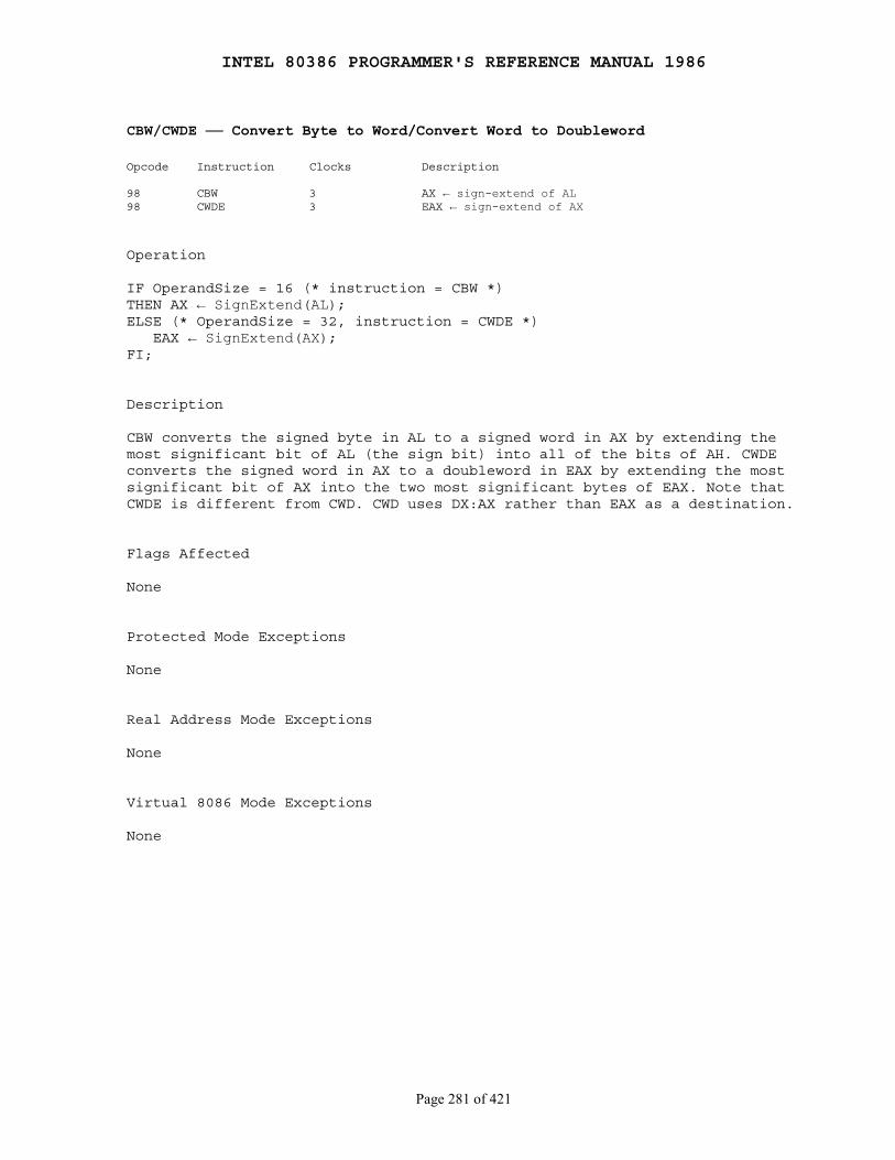
INTEL 80386 PROGRAMMER'S REFERENCE MANUAL 1986
Page 281 of 421
CBW/CWDE ── Convert Byte to Word/Convert Word to Doubleword
Opcode Instruction Clocks Description
98 CBW 3 AX ← sign-extend of AL98 CWDE 3 EAX ← sign-extend of AX
Operation
IF OperandSize = 16 (* instruction = CBW *)THEN AX ← SignExtend(AL);ELSE (* OperandSize = 32, instruction = CWDE *) EAX ← SignExtend(AX);FI;
Description
CBW converts the signed byte in AL to a signed word in AX by extending themost significant bit of AL (the sign bit) into all of the bits of AH. CWDEconverts the signed word in AX to a doubleword in EAX by extending the mostsignificant bit of AX into the two most significant bytes of EAX. Note thatCWDE is different from CWD. CWD uses DX:AX rather than EAX as a destination.
Flags Affected
None
Protected Mode Exceptions
None
Real Address Mode Exceptions
None
Virtual 8086 Mode Exceptions
None
INTEL 80386 PROGRAMMER'S REFERENCE MANUAL 1986
Page 282 of 421
CLC ── Clear Carry Flag
Opcode Instruction Clocks Description
F8 CLC 2 Clear carry flag
Operation
CF ← 0;
Description
CLC sets the carry flag to zero. It does not affect other flags orregisters.
Flags Affected
CF = 0
Protected Mode Exceptions
None
Real Address Mode Exceptions
None
Virtual 8086 Mode Exceptions
None
INTEL 80386 PROGRAMMER'S REFERENCE MANUAL 1986
Page 283 of 421
CLD ── Clear Direction Flag
Opcode Instruction Clocks Description
FC CLD 2 Clear direction flag; SI and DI will increment during string instructions
Operation
DF ← 0;
Description
CLD clears the direction flag. No other flags or registers are affected.After CLD is executed, string operations will increment the index registers(SI and/or DI) that they use.
Flags Affected
DF = 0
Protected Mode Exceptions
None
Real Address Mode Exceptions
None
Virtual 8086 Mode Exceptions
None
INTEL 80386 PROGRAMMER'S REFERENCE MANUAL 1986
Page 284 of 421
CLI ── Clear Interrupt Flag
Opcode Instruction Clocks Description
FA CLI 3 Clear interrupt flag; interrupts disabled
Operation
IF ← 0;
Description
CLI clears the interrupt flag if the current privilege level is at least asprivileged as IOPL. No other flags are affected. External interrupts are notrecognized at the end of the CLI instruction or from that point on until theinterrupt flag is set.
Flags Affected
IF = 0
Protected Mode Exceptions
#GP(0) if the current privilege level is greater (has less privilege) thanthe IOPL in the flags register. IOPL specifies the least privileged level atwhich I/O can be performed.
Real Address Mode Exceptions
None
Virtual 8086 Mode Exceptions
#GP(0) as for Protected Mode
INTEL 80386 PROGRAMMER'S REFERENCE MANUAL 1986
Page 285 of 421
CLTS ── Clear Task-Switched Flag in CR0
Opcode Instruction Clocks Description
OF 06 CLTS 5 Clear task-switched flag
Operation
TS Flag in CR0 ← 0;
Description
CLTS clears the task-switched (TS) flag in register CR0. This flag is set bythe 80386 every time a task switch occurs. The TS flag is used to manageprocessor extensions as follows:
● Every execution of an ESC instruction is trapped if the TS flag is set.
● Execution of a WAIT instruction is trapped if the MP flag and the TS flag are both set.
Thus, if a task switch was made after an ESC instruction was begun, theprocessor extension's context may need to be saved before a new ESCinstruction can be issued. The fault handler saves the context and resetsthe TS flag.
CLTS appears in operating system software, not in application programs. Itis a privileged instruction that can only be executed at privilege level 0.
Flags Affected
TS = 0 (TS is in CR0, not the flag register)
Protected Mode Exceptions
#GP(0) if CLTS is executed with a current privilege level other than 0
Real Address Mode Exceptions
None (valid in Real Address Mode to allow initialization for ProtectedMode)
Virtual 8086 Mode Exceptions
Same exceptions as in Real Address Mode
INTEL 80386 PROGRAMMER'S REFERENCE MANUAL 1986
Page 286 of 421
CMC ── Complement Carry Flag
Opcode Instruction Clocks Description
F5 CMC 2 Complement carry flag
Operation
CF ← NOT CF;
Description
CMC reverses the setting of the carry flag. No other flags are affected.
Flags Affected
CF as described above
Protected Mode Exceptions
None
Real Address Mode Exceptions
None
Virtual 8086 Mode Exceptions
None
INTEL 80386 PROGRAMMER'S REFERENCE MANUAL 1986
Page 287 of 421
CMP ── Compare Two Operands
Opcode Instruction Clocks Description
3C ib CMP AL,imm8 2 Compare immediate byte to AL3D iw CMP AX,imm16 2 Compare immediate word to AX3D id CMP EAX,imm32 2 Compare immediate dword to EAX80 /7 ib CMP r/m8,imm8 2/5 Compare immediate byte to r/m byte81 /7 iw CMP r/m16,imm16 2/5 Compare immediate word to r/m word81 /7 id CMP r/m32,imm32 2/5 Compare immediate dword to r/m dword83 /7 ib CMP r/m16,imm8 2/5 Compare sign extended immediate byte to r/m word83 /7 ib CMP r/m32,imm8 2/5 Compare sign extended immediate byte to r/m dword38 /r CMP r/m8,r8 2/5 Compare byte register to r/m byte39 /r CMP r/m16,r16 2/5 Compare word register to r/m word39 /r CMP r/m32,r32 2/5 Compare dword register to r/m dword3A /r CMP r8,r/m8 2/6 Compare r/m byte to byte register3B /r CMP r16,r/m16 2/6 Compare r/m word to word register3B /r CMP r32,r/m32 2/6 Compare r/m dword to dword register
Operation
LeftSRC - SignExtend(RightSRC);(* CMP does not store a result; its purpose is to set the flags *)
Description
CMP subtracts the second operand from the first but, unlike the SUBinstruction, does not store the result; only the flags are changed. CMP istypically used in conjunction with conditional jumps and the SETccinstruction. (Refer to Appendix D for the list of signed and unsigned flagtests provided.) If an operand greater than one byte is compared to animmediate byte, the byte value is first sign-extended.
Flags Affected
OF, SF, ZF, AF, PF, and CF as described in Appendix C
Protected Mode Exceptions
#GP(0) for an illegal memory operand effective address in the CS, DS, ES,FS, or GS segments; #SS(0) for an illegal address in the SS segment;#PF(fault-code) for a page fault
Real Address Mode Exceptions
Interrupt 13 if any part of the operand would lie outside of the effectiveaddress space from 0 to 0FFFFH
Virtual 8086 Mode Exceptions
Same exceptions as in Real Address Mode; #PF(fault-code) for a page fault.
INTEL 80386 PROGRAMMER'S REFERENCE MANUAL 1986
Page 288 of 421
CMPS/CMPSB/CMPSW/CMPSD ── Compare String Operands
Opcode Instruction Clocks Description
A6 CMPS m8,m8 10 Compare bytes ES:[(E)DI] (second operand) with [(E)SI] (first operand)A7 CMPS m16,m16 10 Compare words ES:[(E)DI] (second operand) with [(E)SI] (first operand)A7 CMPS m32,m32 10 Compare dwords ES:[(E)DI] (second operand) with [(E)SI] (first operand)A6 CMPSB 10 Compare bytes ES:[(E)DI] with DS:[SI]A7 CMPSW 10 Compare words ES:[(E)DI] DS:[SI]A7 CMPSD 10 Compare dwords ES:[(E)DI] with DS:[SI]
Operation
IF (instruction = CMPSD) OR (instruction has operands of type DWORD)THEN OperandSize ← 32;ELSE OperandSize ← 16;FI;IF AddressSize = 16THEN use SI for source-index and DI for destination-indexELSE (* AddressSize = 32 *) use ESI for source-index and EDI for destination-index;FI;IF byte type of instructionTHEN [source-index] - [destination-index]; (* byte comparison *) IF DF = 0 THEN IncDec ← 1 ELSE IncDec ← -1; FI;ELSE IF OperandSize = 16 THEN [source-index] - [destination-index]; (* word comparison *) IF DF = 0 THEN IncDec ← 2 ELSE IncDec ← -2; FI; ELSE (* OperandSize = 32 *) [source-index] - [destination-index]; (* dword comparison *) IF DF = 0 THEN IncDec ← 4 ELSE IncDec ← -4; FI; FI;FI;source-index = source-index + IncDec;destination-index = destination-index + IncDec;
Description
CMPS compares the byte, word, or doubleword pointed to by the source-indexregister with the byte, word, or doubleword pointed to by thedestination-index register.
If the address-size attribute of this instruction is 16 bits, SI and DIwill be used for source- and destination-index registers; otherwise ESI andEDI will be used. Load the correct index values into SI and DI (or ESI andEDI) before executing CMPS.
The comparison is done by subtracting the operand indexed bythe destination-index register from the operand indexed by the source-indexregister.
INTEL 80386 PROGRAMMER'S REFERENCE MANUAL 1986
Page 289 of 421
Note that the direction of subtraction for CMPS is [SI] - [DI] or[ESI] - [EDI]. The left operand (SI or ESI) is the source and the rightoperand (DI or EDI) is the destination. This is the reverse of the usualIntel convention in which the left operand is the destination and the rightoperand is the source.
The result of the subtraction is not stored; only the flags reflect thechange. The types of the operands determine whether bytes, words, ordoublewords are compared. For the first operand (SI or ESI), the DS registeris used, unless a segment override byte is present. The second operand (DIor EDI) must be addressable from the ES register; no segment override ispossible.
After the comparison is made, both the source-index register anddestination-index register are automatically advanced. If the direction flagis 0 (CLD was executed), the registers increment; if the direction flag is 1(STD was executed), the registers decrement. The registers increment ordecrement by 1 if a byte is compared, by 2 if a word is compared, or by 4 ifa doubleword is compared.
CMPSB, CMPSW and CMPSD are synonyms for the byte, word, anddoubleword CMPS instructions, respectively.
CMPS can be preceded by the REPE or REPNE prefix for block comparison of CXor ECX bytes, words, or doublewords. Refer to the description of the REPinstruction for more information on this operation.
Flags Affected
OF, SF, ZF, AF, PF, and CF as described in Appendix C
Protected Mode Exceptions
#GP(0) for an illegal memory operand effective address in the CS, DS, ES,FS, or GS segments; #SS(0) for an illegal address in the SS segment;#PF(fault-code) for a page fault
Real Address Mode Exceptions
Interrupt 13 if any part of the operand would lie outside of the effectiveaddress space from 0 to 0FFFFH
Virtual 8086 Mode Exceptions
Same exceptions as in Real Address Mode; #PF (fault-code) for a page fault
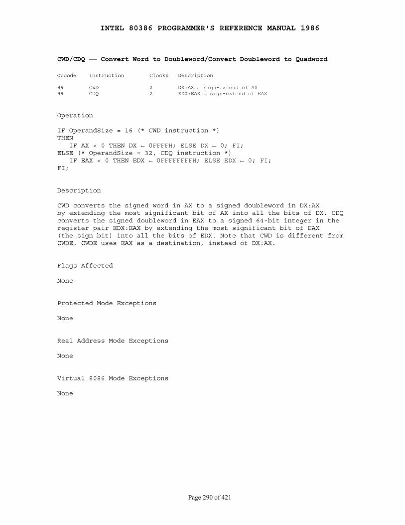
INTEL 80386 PROGRAMMER'S REFERENCE MANUAL 1986
Page 290 of 421
CWD/CDQ ── Convert Word to Doubleword/Convert Doubleword to Quadword
Opcode Instruction Clocks Description
99 CWD 2 DX:AX ← sign-extend of AX99 CDQ 2 EDX:EAX ← sign-extend of EAX
Operation
IF OperandSize = 16 (* CWD instruction *)THEN IF AX < 0 THEN DX ← 0FFFFH; ELSE DX ← 0; FI;ELSE (* OperandSize = 32, CDQ instruction *) IF EAX < 0 THEN EDX ← 0FFFFFFFFH; ELSE EDX ← 0; FI;FI;
Description
CWD converts the signed word in AX to a signed doubleword in DX:AXby extending the most significant bit of AX into all the bits of DX. CDQconverts the signed doubleword in EAX to a signed 64-bit integer in theregister pair EDX:EAX by extending the most significant bit of EAX(the sign bit) into all the bits of EDX. Note that CWD is different fromCWDE. CWDE uses EAX as a destination, instead of DX:AX.
Flags Affected
None
Protected Mode Exceptions
None
Real Address Mode Exceptions
None
Virtual 8086 Mode Exceptions
None

INTEL 80386 PROGRAMMER'S REFERENCE MANUAL 1986
Page 291 of 421
DAA ── Decimal Adjust AL after Addition
Opcode Instruction Clocks Description
27 DAA 4 Decimal adjust AL after addition
Operation
IF ((AL AND 0FH) > 9) OR (AF = 1)THEN AL ← AL + 6; AF ← 1;ELSE AF ← 0;FI;IF (AL > 9FH) OR (CF = 1)THEN AL ← AL + 60H; CF ← 1;ELSE CF ← 0;FI;
Description
Execute DAA only after executing an ADD instruction that leaves atwo-BCD-digit byte result in the AL register. The ADD operands shouldconsist of two packed BCD digits. The DAA instruction adjusts AL tocontain the correct two-digit packed decimal result.
Flags Affected
AF and CF as described above; SF, ZF, PF, and CF as described inAppendix C.
Protected Mode Exceptions
None
Real Address Mode Exceptions
None
Virtual 8086 Mode Exceptions
None
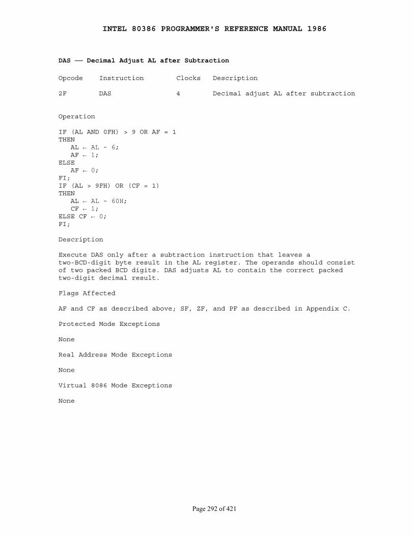
INTEL 80386 PROGRAMMER'S REFERENCE MANUAL 1986
Page 292 of 421
DAS ── Decimal Adjust AL after Subtraction
Opcode Instruction Clocks Description
2F DAS 4 Decimal adjust AL after subtraction
Operation
IF (AL AND 0FH) > 9 OR AF = 1THEN AL ← AL - 6; AF ← 1;ELSE AF ← 0;FI;IF (AL > 9FH) OR (CF = 1)THEN AL ← AL - 60H; CF ← 1;ELSE CF ← 0;FI;
Description
Execute DAS only after a subtraction instruction that leaves atwo-BCD-digit byte result in the AL register. The operands should consistof two packed BCD digits. DAS adjusts AL to contain the correct packedtwo-digit decimal result.
Flags Affected
AF and CF as described above; SF, ZF, and PF as described in Appendix C.
Protected Mode Exceptions
None
Real Address Mode Exceptions
None
Virtual 8086 Mode Exceptions
None
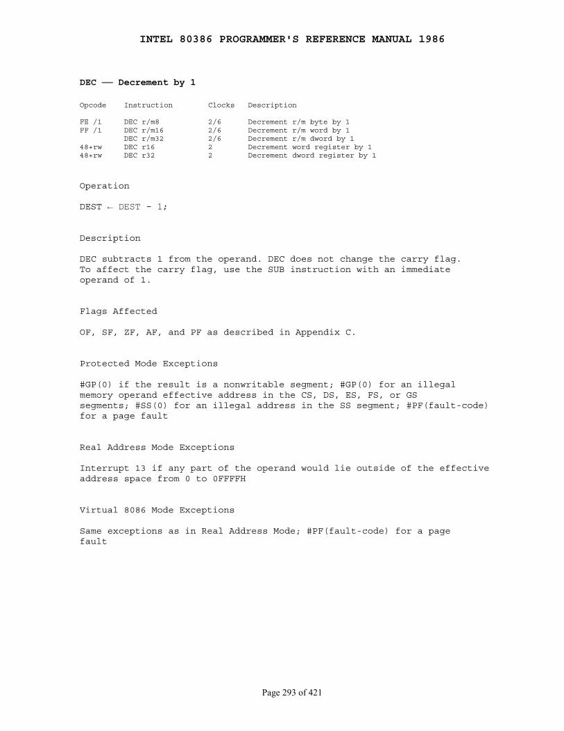
INTEL 80386 PROGRAMMER'S REFERENCE MANUAL 1986
Page 293 of 421
DEC ── Decrement by 1
Opcode Instruction Clocks Description
FE /1 DEC r/m8 2/6 Decrement r/m byte by 1FF /1 DEC r/m16 2/6 Decrement r/m word by 1 DEC r/m32 2/6 Decrement r/m dword by 148+rw DEC r16 2 Decrement word register by 148+rw DEC r32 2 Decrement dword register by 1
Operation
DEST ← DEST - 1;
Description
DEC subtracts 1 from the operand. DEC does not change the carry flag.To affect the carry flag, use the SUB instruction with an immediateoperand of 1.
Flags Affected
OF, SF, ZF, AF, and PF as described in Appendix C.
Protected Mode Exceptions
#GP(0) if the result is a nonwritable segment; #GP(0) for an illegalmemory operand effective address in the CS, DS, ES, FS, or GSsegments; #SS(0) for an illegal address in the SS segment; #PF(fault-code)for a page fault
Real Address Mode Exceptions
Interrupt 13 if any part of the operand would lie outside of the effectiveaddress space from 0 to 0FFFFH
Virtual 8086 Mode Exceptions
Same exceptions as in Real Address Mode; #PF(fault-code) for a pagefault
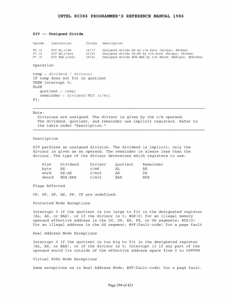
INTEL 80386 PROGRAMMER'S REFERENCE MANUAL 1986
Page 294 of 421
DIV ── Unsigned Divide
Opcode Instruction Clocks Description
F6 /6 DIV AL,r/m8 14/17 Unsigned divide AX by r/m byte (AL=Quo, AH=Rem)F7 /6 DIV AX,r/m16 22/25 Unsigned divide DX:AX by r/m word (AX=Quo, DX=Rem)F7 /6 DIV EAX,r/m32 38/41 Unsigned divide EDX:EAX by r/m dword (EAX=Quo, EDX=Rem)
Operation
temp ← dividend / divisor;IF temp does not fit in quotientTHEN Interrupt 0;ELSE quotient ← temp; remainder ← dividend MOD (r/m);FI;
───────────────────────────────────────────────────────────────────────────Note: Divisions are unsigned. The divisor is given by the r/m operand. The dividend, quotient, and remainder use implicit registers. Refer to the table under "Description."───────────────────────────────────────────────────────────────────────────
Description
DIV performs an unsigned division. The dividend is implicit; only thedivisor is given as an operand. The remainder is always less than thedivisor. The type of the divisor determines which registers to use:
Size Dividend Divisor Quotient Remainder byte AX r/m8 AL AH word DX:AX r/m16 AX DX dword EDX:EAX r/m32 EAX EDX
Flags Affected
OF, SF, ZF, AR, PF, CF are undefined.
Protected Mode Exceptions
Interrupt 0 if the quotient is too large to fit in the designated register(AL, AX, or EAX), or if the divisor is 0; #GP(0) for an illegal memoryoperand effective address in the CS, DS, ES, FS, or GS segments; #SS(0)for an illegal address in the SS segment; #PF(fault-code) for a page fault
Real Address Mode Exceptions
Interrupt 0 if the quotient is too big to fit in the designated register(AL, AX, or EAX), or if the divisor is 0; Interrupt 13 if any part of theoperand would lie outside of the effective address space from 0 to 0FFFFH
Virtual 8086 Mode Exceptions
Same exceptions as in Real Address Mode; #PF(fault-code) for a page fault.

INTEL 80386 PROGRAMMER'S REFERENCE MANUAL 1986
Page 295 of 421
ENTER ── Make Stack Frame for Procedure Parameters
Opcode Instruction Clocks Description
C8 iw 00 ENTER imm16,0 10 Make procedure stack frameC8 iw 01 ENTER imm16,1 12 Make stack frame for procedure parametersC8 iw ib ENTER imm16,imm8 15+4(n-1) Make stack frame for procedure parameters
Operation
level ← level MOD 32IF OperandSize = 16 THEN Push(BP) ELSE Push (EBP) FI; (* Save stack pointer *)frame-ptr ← eSPIF level > 0THEN (* level is rightmost parameter *) FOR i ← 1 TO level - 1 DO IF OperandSize = 16 THEN BP ← BP - 2; Push[BP] ELSE (* OperandSize = 32 *) EBP ← EBP - 4; Push[EBP]; FI; OD; Push(frame-ptr)FI;IF OperandSize = 16 THEN BP ← frame-ptr ELSE EBP ← frame-ptr; FI;IF StackAddrSize = 16THEN SP ← SP - First operand;ELSE ESP ← ESP - ZeroExtend(First operand);FI;
Description
ENTER creates the stack frame required by most block-structuredhigh-level languages. The first operand specifies the number of bytes ofdynamic storage allocated on the stack for the routine being entered.The second operand gives the lexical nesting level (0 to 31) of the routinewithin the high-level language source code. It determines the number ofstack frame pointers copied into the new stack frame from the precedingframe. BP (or EBP, if the operand-size attribute is 32 bits) is the currentstack frame pointer.
If the operand-size attribute is 16 bits, the processor uses BP as theframe pointer and SP as the stack pointer. If the operand-size attribute is32 bits, the processor uses EBP for the frame pointer and ESP for the stackpointer.
If the second operand is 0, ENTER pushes the frame pointer (BP orEBP) onto the stack; ENTER then subtracts the first operand from thestack pointer and sets the frame pointer to the current stack-pointervalue.
INTEL 80386 PROGRAMMER'S REFERENCE MANUAL 1986
Page 296 of 421
For example, a procedure with 12 bytes of local variables would have anENTER 12,0 instruction at its entry point and a LEAVE instructionbefore every RET. The 12 local bytes would be addressed as negativeoffsets from the frame pointer.
Flags Affected
None
Protected Mode Exceptions
#SS(0) if SP or ESP would exceed the stack limit at any point duringinstruction execution; #PF(fault-code) for a page fault
Real Address Mode Exceptions
None
Virtual 8086 Mode Exceptions
None
INTEL 80386 PROGRAMMER'S REFERENCE MANUAL 1986
Page 297 of 421
HLT ── Halt
Opcode Instruction Clocks Description
F4 HLT 5 Halt
Operation
Enter Halt state;
Description
HALT stops instruction execution and places the 80386 in a HALT state.An enabled interrupt, NMI, or a reset will resume execution. If aninterrupt (including NMI) is used to resume execution after HLT, the savedCS:IP (or CS:EIP) value points to the instruction following HLT.
Flags Affected
None
Protected Mode Exceptions
HLT is a privileged instruction; #GP(0) if the current privilege level isnot 0
Real Address Mode Exceptions
None
Virtual 8086 Mode Exceptions
#GP(0); HLT is a privileged instruction

INTEL 80386 PROGRAMMER'S REFERENCE MANUAL 1986
Page 298 of 421
IDIV ── Signed Divide
Opcode Instruction Clocks Description
F6 /7 IDIV r/m8 19 Signed divide AX by r/m byte (AL=Quo, AH=Rem)F7 /7 IDIV AX,r/m16 27 Signed divide DX:AX by EA word (AX=Quo, DX=Rem)F7 /7 IDIV EAX,r/m32 43 Signed divide EDX:EAX by DWORD byte (EAX=Quo, EDX=Rem)
Operation
temp ← dividend / divisor;IF temp does not fit in quotientTHEN Interrupt 0;ELSE quotient ← temp; remainder ← dividend MOD (r/m);FI;
───────────────────────────────────────────────────────────────────────────Notes: Divisions are signed. The divisor is given by the r/m operand. The dividend, quotient, and remainder use implicit registers. Refer to the table under "Description."───────────────────────────────────────────────────────────────────────────
Description
IDIV performs a signed division. The dividend, quotient, and remainderare implicitly allocated to fixed registers. Only the divisor is given asan explicit r/m operand. The type of the divisor determines which registersto use as follows:
Size Divisor Quotient Remainder Dividendbyte r/m8 AL AH AXword r/m16 AX DX DX:AXdword r/m32 EAX EDX EDX:EAX
If the resulting quotient is too large to fit in the destination, or if thedivision is 0, an Interrupt 0 is generated. Nonintegral quotients aretruncated toward 0. The remainder has the same sign as the dividendand the absolute value of the remainder is always less than the absolutevalue of the divisor.
Flags Affected
OF, SF, ZF, AR, PF, CF are undefined.
Protected Mode Exceptions
Interrupt 0 if the quotient is too large to fit in the designated register(AL or AX), or if the divisor is 0; #GP (0) for an illegal memory operandeffective address in the CS, DS, ES, FS, or GS segments; #SS(0) for anillegal address in the SS segment; #PF(fault-code) for a page fault
INTEL 80386 PROGRAMMER'S REFERENCE MANUAL 1986
Page 299 of 421
Real Address Mode Exceptions
Interrupt 0 if the quotient is too large to fit in the designated register(AL or AX), or if the divisor is 0; Interrupt 13 if any part of the operandwould lie outside of the effective address space from 0 to 0FFFFH
Virtual 8086 Mode Exceptions
Same exceptions as in Real Address Mode; #PF(fault-code) for a pagefault
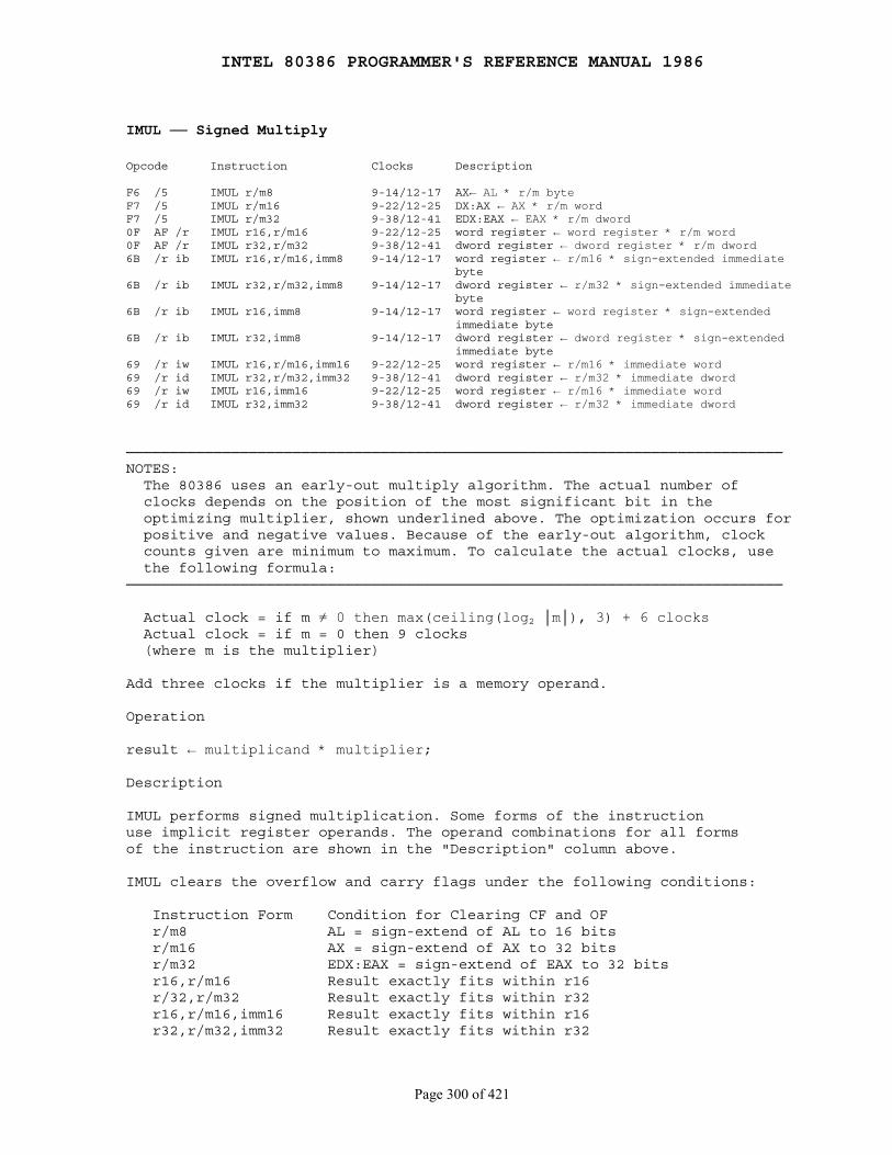
INTEL 80386 PROGRAMMER'S REFERENCE MANUAL 1986
Page 300 of 421
IMUL ── Signed Multiply
Opcode Instruction Clocks Description
F6 /5 IMUL r/m8 9-14/12-17 AX← AL * r/m byteF7 /5 IMUL r/m16 9-22/12-25 DX:AX ← AX * r/m wordF7 /5 IMUL r/m32 9-38/12-41 EDX:EAX ← EAX * r/m dword0F AF /r IMUL r16,r/m16 9-22/12-25 word register ← word register * r/m word0F AF /r IMUL r32,r/m32 9-38/12-41 dword register ← dword register * r/m dword6B /r ib IMUL r16,r/m16,imm8 9-14/12-17 word register ← r/m16 * sign-extended immediate byte6B /r ib IMUL r32,r/m32,imm8 9-14/12-17 dword register ← r/m32 * sign-extended immediate byte6B /r ib IMUL r16,imm8 9-14/12-17 word register ← word register * sign-extended immediate byte6B /r ib IMUL r32,imm8 9-14/12-17 dword register ← dword register * sign-extended immediate byte69 /r iw IMUL r16,r/m16,imm16 9-22/12-25 word register ← r/m16 * immediate word69 /r id IMUL r32,r/m32,imm32 9-38/12-41 dword register ← r/m32 * immediate dword69 /r iw IMUL r16,imm16 9-22/12-25 word register ← r/m16 * immediate word69 /r id IMUL r32,imm32 9-38/12-41 dword register ← r/m32 * immediate dword
───────────────────────────────────────────────────────────────────────────NOTES: The 80386 uses an early-out multiply algorithm. The actual number of clocks depends on the position of the most significant bit in the optimizing multiplier, shown underlined above. The optimization occurs for positive and negative values. Because of the early-out algorithm, clock counts given are minimum to maximum. To calculate the actual clocks, use the following formula:───────────────────────────────────────────────────────────────────────────
Actual clock = if m ≠ 0 then max(ceiling(log2 │m│), 3) + 6 clocks Actual clock = if m = 0 then 9 clocks (where m is the multiplier)
Add three clocks if the multiplier is a memory operand.
Operation
result ← multiplicand * multiplier;
Description
IMUL performs signed multiplication. Some forms of the instructionuse implicit register operands. The operand combinations for all formsof the instruction are shown in the "Description" column above.
IMUL clears the overflow and carry flags under the following conditions:
Instruction Form Condition for Clearing CF and OF r/m8 AL = sign-extend of AL to 16 bits r/m16 AX = sign-extend of AX to 32 bits r/m32 EDX:EAX = sign-extend of EAX to 32 bits r16,r/m16 Result exactly fits within r16 r/32,r/m32 Result exactly fits within r32 r16,r/m16,imm16 Result exactly fits within r16 r32,r/m32,imm32 Result exactly fits within r32
INTEL 80386 PROGRAMMER'S REFERENCE MANUAL 1986
Page 301 of 421
Flags Affected
OF and CF as described above; SF, ZF, AF, and PF are undefined
Protected Mode Exceptions
#GP(0) for an illegal memory operand effective address in the CS, DS,ES, FS, or GS segments; #SS(0) for an illegal address in the SS segment;#PF(fault-code) for a page fault
Real Address Mode Exceptions
Interrupt 13 if any part of the operand would lie outside of the effectiveaddress space from 0 to 0FFFFH
Virtual 8086 Mode Exceptions
Same exeptions as in Real Address Mode; #PF(fault-code) for a pagefault
Notes
When using the accumulator forms (IMUL r/m8, IMUL r/m16, or IMULr/m32), the result of the multiplication is available even if the overflowflag is set because the result is two times the size of the multiplicandand multiplier. This is large enough to handle any possible result.
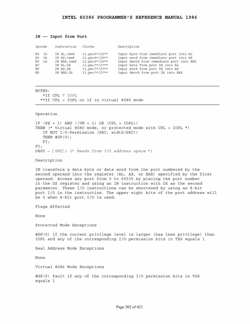
INTEL 80386 PROGRAMMER'S REFERENCE MANUAL 1986
Page 302 of 421
IN ── Input from Port
Opcode Instruction Clocks Description
E4 ib IN AL,imm8 12,pm=6*/26** Input byte from immediate port into ALE5 ib IN AX,imm8 12,pm=6*/26** Input word from immediate port into AXE5 ib IN EAX,imm8 12,pm=6*/26** Input dword from immediate port into EAXEC IN AL,DX 13,pm=7*/27** Input byte from port DX into ALED IN AX,DX 13,pm=7*/27** Input word from port DX into AXED IN EAX,DX 13,pm=7*/27** Input dword from port DX into EAX
───────────────────────────────────────────────────────────────────────────NOTES: *If CPL ≤ IOPL **If CPL > IOPL or if in virtual 8086 mode───────────────────────────────────────────────────────────────────────────
Operation
IF (PE = 1) AND ((VM = 1) OR (CPL > IOPL))THEN (* Virtual 8086 mode, or protected mode with CPL > IOPL *) IF NOT I-O-Permission (SRC, width(SRC)) THEN #GP(0); FI;FI;DEST ← [SRC]; (* Reads from I/O address space *)
Description
IN transfers a data byte or data word from the port numbered by thesecond operand into the register (AL, AX, or EAX) specified by the firstoperand. Access any port from 0 to 65535 by placing the port numberin the DX register and using an IN instruction with DX as the secondparameter. These I/O instructions can be shortened by using an 8-bitport I/O in the instruction. The upper eight bits of the port address willbe 0 when 8-bit port I/O is used.
Flags Affected
None
Protected Mode Exceptions
#GP(0) if the current privilege level is larger (has less privilege) thanIOPL and any of the corresponding I/O permission bits in TSS equals 1
Real Address Mode Exceptions
None
Virtual 8086 Mode Exceptions
#GP(0) fault if any of the corresponding I/O permission bits in TSSequals 1
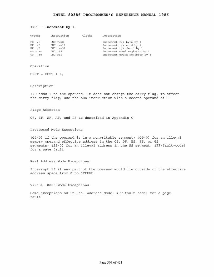
INTEL 80386 PROGRAMMER'S REFERENCE MANUAL 1986
Page 303 of 421
INC ── Increment by 1
Opcode Instruction Clocks Description
FE /0 INC r/m8 Increment r/m byte by 1FF /0 INC r/m16 Increment r/m word by 1FF /6 INC r/m32 Increment r/m dword by 140 + rw INC r16 Increment word register by 140 + rd INC r32 Increment dword register by 1
Operation
DEST ← DEST + 1;
Description
INC adds 1 to the operand. It does not change the carry flag. To affectthe carry flag, use the ADD instruction with a second operand of 1.
Flags Affected
OF, SF, ZF, AF, and PF as described in Appendix C
Protected Mode Exceptions
#GP(0) if the operand is in a nonwritable segment; #GP(0) for an illegalmemory operand effective address in the CS, DS, ES, FS, or GSsegments; #SS(0) for an illegal address in the SS segment; #PF(fault-code)for a page fault
Real Address Mode Exceptions
Interrupt 13 if any part of the operand would lie outside of the effectiveaddress space from 0 to 0FFFFH
Virtual 8086 Mode Exceptions
Same exceptions as in Real Address Mode; #PF(fault-code) for a pagefault
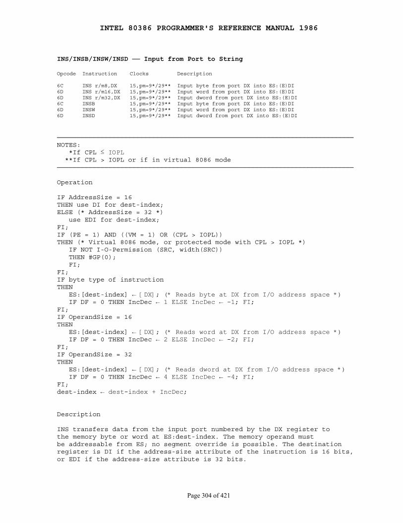
INTEL 80386 PROGRAMMER'S REFERENCE MANUAL 1986
Page 304 of 421
INS/INSB/INSW/INSD ── Input from Port to StringOpcode Instruction Clocks Description
6C INS r/m8,DX 15,pm=9*/29** Input byte from port DX into ES:(E)DI6D INS r/m16,DX 15,pm=9*/29** Input word from port DX into ES:(E)DI6D INS r/m32,DX 15,pm=9*/29** Input dword from port DX into ES:(E)DI6C INSB 15,pm=9*/29** Input byte from port DX into ES:(E)DI6D INSW 15,pm=9*/29** Input word from port DX into ES:(E)DI6D INSD 15,pm=9*/29** Input dword from port DX into ES:(E)DI
───────────────────────────────────────────────────────────────────────────NOTES: *If CPL ≤ IOPL **If CPL > IOPL or if in virtual 8086 mode───────────────────────────────────────────────────────────────────────────
Operation
IF AddressSize = 16THEN use DI for dest-index;ELSE (* AddressSize = 32 *) use EDI for dest-index;FI;IF (PE = 1) AND ((VM = 1) OR (CPL > IOPL))THEN (* Virtual 8086 mode, or protected mode with CPL > IOPL *) IF NOT I-O-Permission (SRC, width(SRC)) THEN #GP(0); FI;FI;IF byte type of instructionTHEN ES:[dest-index] ← [DX]; (* Reads byte at DX from I/O address space *) IF DF = 0 THEN IncDec ← 1 ELSE IncDec ← -1; FI;FI;IF OperandSize = 16THEN ES:[dest-index] ← [DX]; (* Reads word at DX from I/O address space *) IF DF = 0 THEN IncDec ← 2 ELSE IncDec ← -2; FI;FI;IF OperandSize = 32THEN ES:[dest-index] ← [DX]; (* Reads dword at DX from I/O address space *) IF DF = 0 THEN IncDec ← 4 ELSE IncDec ← -4; FI;FI;dest-index ← dest-index + IncDec;
Description
INS transfers data from the input port numbered by the DX register tothe memory byte or word at ES:dest-index. The memory operand mustbe addressable from ES; no segment override is possible. The destinationregister is DI if the address-size attribute of the instruction is 16 bits,or EDI if the address-size attribute is 32 bits.

INTEL 80386 PROGRAMMER'S REFERENCE MANUAL 1986
Page 305 of 421
INS does not allow the specification of the port number as an immediatevalue. The port must be addressed through the DX register value. Loadthe correct value into DX before executing the INS instruction.
The destination address is determined by the contents of the destinationindex register. Load the correct index into the destination index registerbefore executing INS.
After the transfer is made, DI or EDI advances automatically. If thedirection flag is 0 (CLD was executed), DI or EDI increments; if thedirection flag is 1 (STD was executed), DI or EDI decrements. DIincrements or decrements by 1 if a byte is input, by 2 if a word is input,or by 4 if a doubleword is input.
INSB, INSW and INSD are synonyms of the byte, word, and doublewordINS instructions. INS can be preceded by the REP prefix for block input ofCX bytes or words. Refer to the REP instruction for details of thisoperation.
Flags Affected
None
Protected Mode Exceptions
#GP(0) if CPL is numerically greater than IOPL and any of thecorresponding I/O permission bits in TSS equals 1; #GP(0) if thedestination is in a nonwritable segment; #GP(0) for an illegal memoryoperand effective address in the CS, DS, ES, FS, or GS segments; #SS(0) foran illegal address in the SS segment; #PF(fault-code) for a page fault
Real Address Mode Exceptions
Interrupt 13 if any part of the operand would lie outside of the effectiveaddress space from 0 to 0FFFFH
Virtual 8086 Mode Exceptions
#GP(0) fault if any of the corresponding I/O permission bits in TSSequals 1; #PF(fault-code) for a page fault
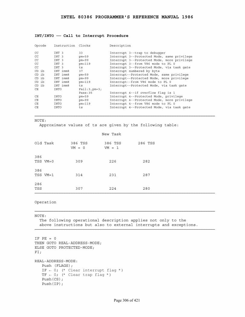
INTEL 80386 PROGRAMMER'S REFERENCE MANUAL 1986
Page 306 of 421
INT/INTO ── Call to Interrupt Procedure
Opcode Instruction Clocks Description
CC INT 3 33 Interrupt 3--trap to debuggerCC INT 3 pm=59 Interrupt 3--Protected Mode, same privilegeCC INT 3 pm=99 Interrupt 3--Protected Mode, more privilegeCC INT 3 pm=119 Interrupt 3--from V86 mode to PL 0CC INT 3 ts Interrupt 3--Protected Mode, via task gateCD ib INT imm8 37 Interrupt numbered by byteCD ib INT imm8 pm=59 Interrupt--Protected Mode, same privilegeCD ib INT imm8 pm=99 Interrupt--Protected Mode, more privilegeCD ib INT imm8 pm=119 Interrupt--from V86 mode to PL 0CD ib INT imm8 ts Interrupt--Protected Mode, via task gateCE INTO Fail:3,pm=3; Pass:35 Interrupt 4--if overflow flag is 1CE INTO pm=59 Interrupt 4--Protected Mode, privilegeCE INTO pm=99 Interrupt 4--Protected Mode, more privilegeCE INTO pm=119 Interrupt 4--from V86 mode to PL 0CE INTO ts Interrupt 4--Protected Mode, via task gate
───────────────────────────────────────────────────────────────────────────NOTE: Approximate values of ts are given by the following table:
New Task
Old Task 386 TSS 386 TSS 286 TSS VM = 0 VM = 1
386TSS VM=0 309 226 282
386TSS VM=1 314 231 287
286TSS 307 224 280───────────────────────────────────────────────────────────────────────────
Operation
───────────────────────────────────────────────────────────────────────────NOTE: The following operational description applies not only to the above instructions but also to external interrupts and exceptions.───────────────────────────────────────────────────────────────────────────
IF PE = 0THEN GOTO REAL-ADDRESS-MODE;ELSE GOTO PROTECTED-MODE;FI;
REAL-ADDRESS-MODE: Push (FLAGS); IF ← 0; (* Clear interrupt flag *) TF ← 0; (* Clear trap flag *) Push(CS); Push(IP);
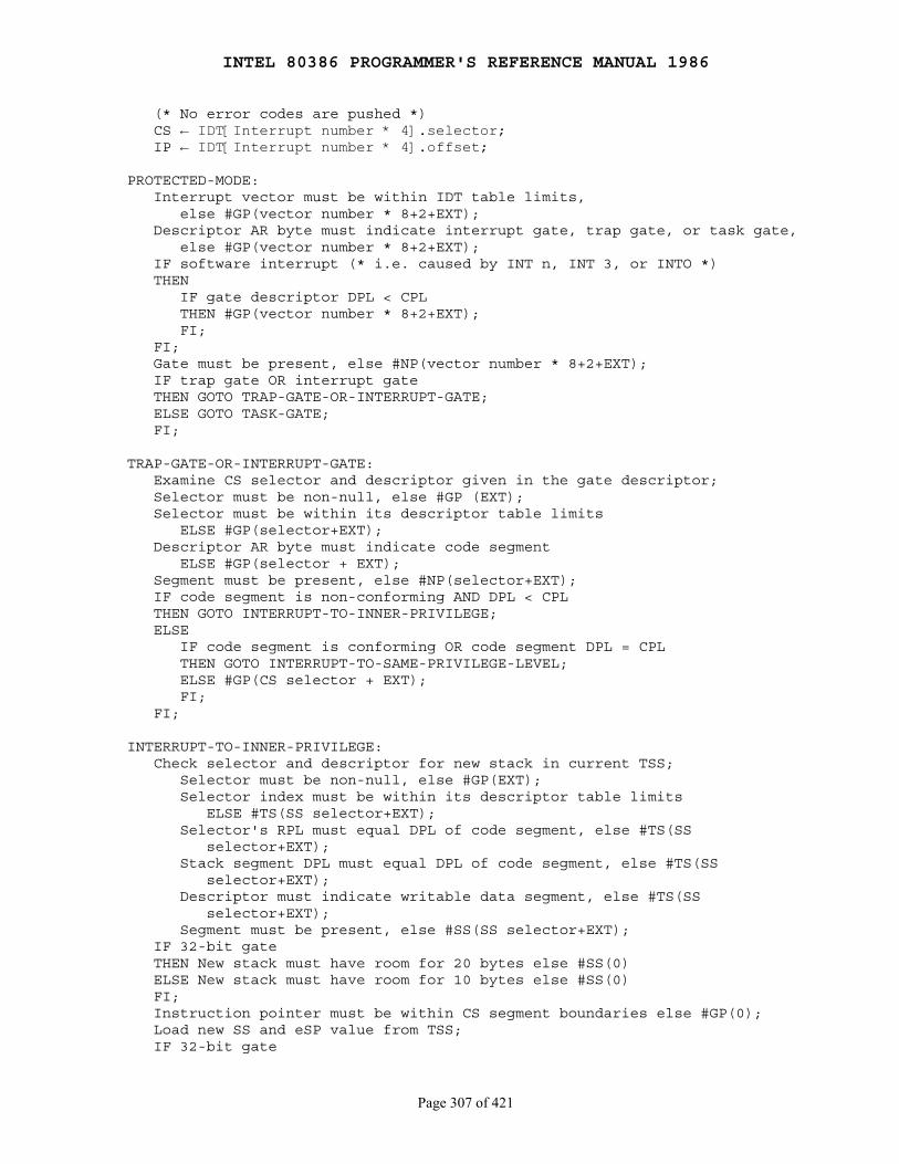
INTEL 80386 PROGRAMMER'S REFERENCE MANUAL 1986
Page 307 of 421
(* No error codes are pushed *) CS ← IDT[Interrupt number * 4].selector; IP ← IDT[Interrupt number * 4].offset;
PROTECTED-MODE: Interrupt vector must be within IDT table limits, else #GP(vector number * 8+2+EXT); Descriptor AR byte must indicate interrupt gate, trap gate, or task gate, else #GP(vector number * 8+2+EXT); IF software interrupt (* i.e. caused by INT n, INT 3, or INTO *) THEN IF gate descriptor DPL < CPL THEN #GP(vector number * 8+2+EXT); FI; FI; Gate must be present, else #NP(vector number * 8+2+EXT); IF trap gate OR interrupt gate THEN GOTO TRAP-GATE-OR-INTERRUPT-GATE; ELSE GOTO TASK-GATE; FI;
TRAP-GATE-OR-INTERRUPT-GATE: Examine CS selector and descriptor given in the gate descriptor; Selector must be non-null, else #GP (EXT); Selector must be within its descriptor table limits ELSE #GP(selector+EXT); Descriptor AR byte must indicate code segment ELSE #GP(selector + EXT); Segment must be present, else #NP(selector+EXT); IF code segment is non-conforming AND DPL < CPL THEN GOTO INTERRUPT-TO-INNER-PRIVILEGE; ELSE IF code segment is conforming OR code segment DPL = CPL THEN GOTO INTERRUPT-TO-SAME-PRIVILEGE-LEVEL; ELSE #GP(CS selector + EXT); FI; FI;
INTERRUPT-TO-INNER-PRIVILEGE: Check selector and descriptor for new stack in current TSS; Selector must be non-null, else #GP(EXT); Selector index must be within its descriptor table limits ELSE #TS(SS selector+EXT); Selector's RPL must equal DPL of code segment, else #TS(SS selector+EXT); Stack segment DPL must equal DPL of code segment, else #TS(SS selector+EXT); Descriptor must indicate writable data segment, else #TS(SS selector+EXT); Segment must be present, else #SS(SS selector+EXT); IF 32-bit gate THEN New stack must have room for 20 bytes else #SS(0) ELSE New stack must have room for 10 bytes else #SS(0) FI; Instruction pointer must be within CS segment boundaries else #GP(0); Load new SS and eSP value from TSS; IF 32-bit gate
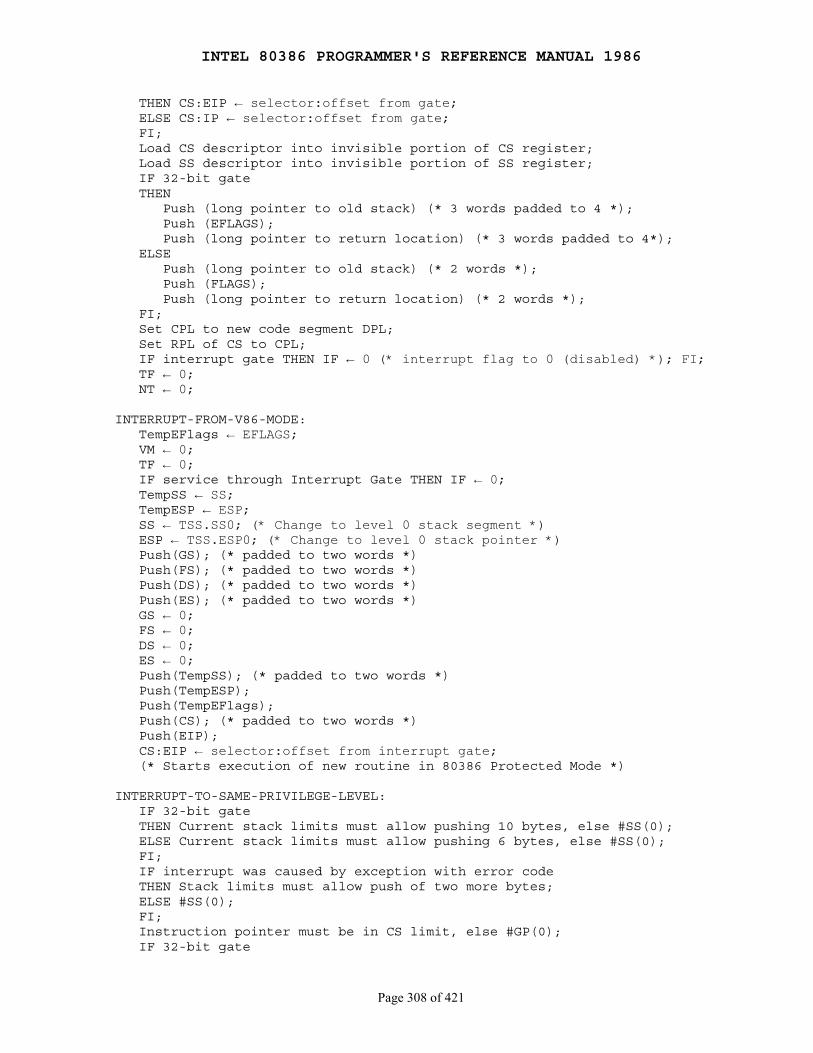
INTEL 80386 PROGRAMMER'S REFERENCE MANUAL 1986
Page 308 of 421
THEN CS:EIP ← selector:offset from gate; ELSE CS:IP ← selector:offset from gate; FI; Load CS descriptor into invisible portion of CS register; Load SS descriptor into invisible portion of SS register; IF 32-bit gate THEN Push (long pointer to old stack) (* 3 words padded to 4 *); Push (EFLAGS); Push (long pointer to return location) (* 3 words padded to 4*); ELSE Push (long pointer to old stack) (* 2 words *); Push (FLAGS); Push (long pointer to return location) (* 2 words *); FI; Set CPL to new code segment DPL; Set RPL of CS to CPL; IF interrupt gate THEN IF ← 0 (* interrupt flag to 0 (disabled) *); FI; TF ← 0; NT ← 0;
INTERRUPT-FROM-V86-MODE: TempEFlags ← EFLAGS; VM ← 0; TF ← 0; IF service through Interrupt Gate THEN IF ← 0; TempSS ← SS; TempESP ← ESP; SS ← TSS.SS0; (* Change to level 0 stack segment *) ESP ← TSS.ESP0; (* Change to level 0 stack pointer *) Push(GS); (* padded to two words *) Push(FS); (* padded to two words *) Push(DS); (* padded to two words *) Push(ES); (* padded to two words *) GS ← 0; FS ← 0; DS ← 0; ES ← 0; Push(TempSS); (* padded to two words *) Push(TempESP); Push(TempEFlags); Push(CS); (* padded to two words *) Push(EIP); CS:EIP ← selector:offset from interrupt gate; (* Starts execution of new routine in 80386 Protected Mode *)
INTERRUPT-TO-SAME-PRIVILEGE-LEVEL: IF 32-bit gate THEN Current stack limits must allow pushing 10 bytes, else #SS(0); ELSE Current stack limits must allow pushing 6 bytes, else #SS(0); FI; IF interrupt was caused by exception with error code THEN Stack limits must allow push of two more bytes; ELSE #SS(0); FI; Instruction pointer must be in CS limit, else #GP(0); IF 32-bit gate
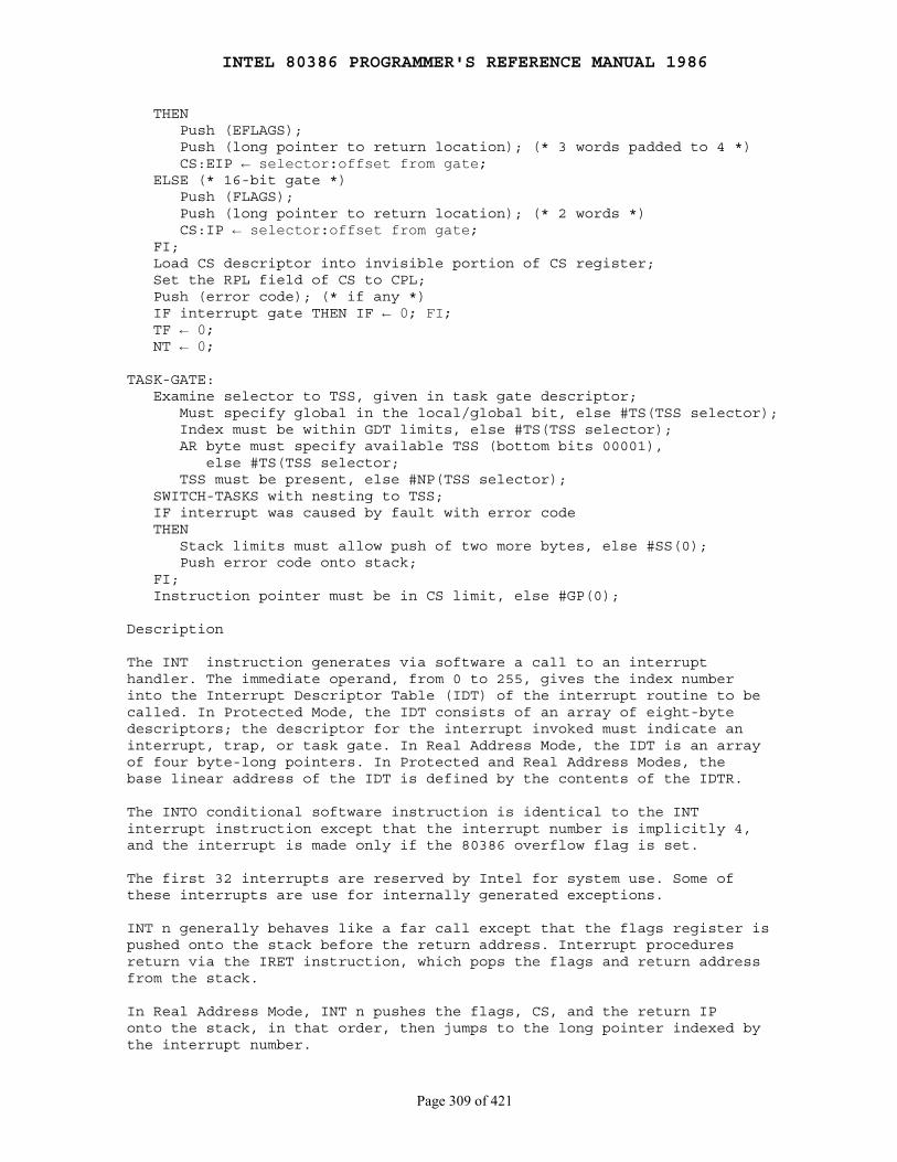
INTEL 80386 PROGRAMMER'S REFERENCE MANUAL 1986
Page 309 of 421
THEN Push (EFLAGS); Push (long pointer to return location); (* 3 words padded to 4 *) CS:EIP ← selector:offset from gate; ELSE (* 16-bit gate *) Push (FLAGS); Push (long pointer to return location); (* 2 words *) CS:IP ← selector:offset from gate; FI; Load CS descriptor into invisible portion of CS register; Set the RPL field of CS to CPL; Push (error code); (* if any *) IF interrupt gate THEN IF ← 0; FI; TF ← 0; NT ← 0;
TASK-GATE: Examine selector to TSS, given in task gate descriptor; Must specify global in the local/global bit, else #TS(TSS selector); Index must be within GDT limits, else #TS(TSS selector); AR byte must specify available TSS (bottom bits 00001), else #TS(TSS selector; TSS must be present, else #NP(TSS selector); SWITCH-TASKS with nesting to TSS; IF interrupt was caused by fault with error code THEN Stack limits must allow push of two more bytes, else #SS(0); Push error code onto stack; FI; Instruction pointer must be in CS limit, else #GP(0);
Description
The INT instruction generates via software a call to an interrupthandler. The immediate operand, from 0 to 255, gives the index numberinto the Interrupt Descriptor Table (IDT) of the interrupt routine to becalled. In Protected Mode, the IDT consists of an array of eight-bytedescriptors; the descriptor for the interrupt invoked must indicate aninterrupt, trap, or task gate. In Real Address Mode, the IDT is an arrayof four byte-long pointers. In Protected and Real Address Modes, thebase linear address of the IDT is defined by the contents of the IDTR.
The INTO conditional software instruction is identical to the INTinterrupt instruction except that the interrupt number is implicitly 4,and the interrupt is made only if the 80386 overflow flag is set.
The first 32 interrupts are reserved by Intel for system use. Some ofthese interrupts are use for internally generated exceptions.
INT n generally behaves like a far call except that the flags register ispushed onto the stack before the return address. Interrupt proceduresreturn via the IRET instruction, which pops the flags and return addressfrom the stack.
In Real Address Mode, INT n pushes the flags, CS, and the return IPonto the stack, in that order, then jumps to the long pointer indexed bythe interrupt number.

INTEL 80386 PROGRAMMER'S REFERENCE MANUAL 1986
Page 310 of 421
Flags Affected
None
Protected Mode Exceptions
#GP, #NP, #SS, and #TS as indicated under "Operation" above
Real Address Mode Exceptions
None; if the SP or ESP = 1, 3, or 5 before executing INT or INTO,the 80386 will shut down due to insufficient stack space
Virtual 8086 Mode Exceptions
#GP(0) fault if IOPL is less than 3, for INT only, to permit emulation;Interrupt 3 (0CCH) generates Interrupt 3; INTO generates Interrupt 4if the overflow flag equals 1
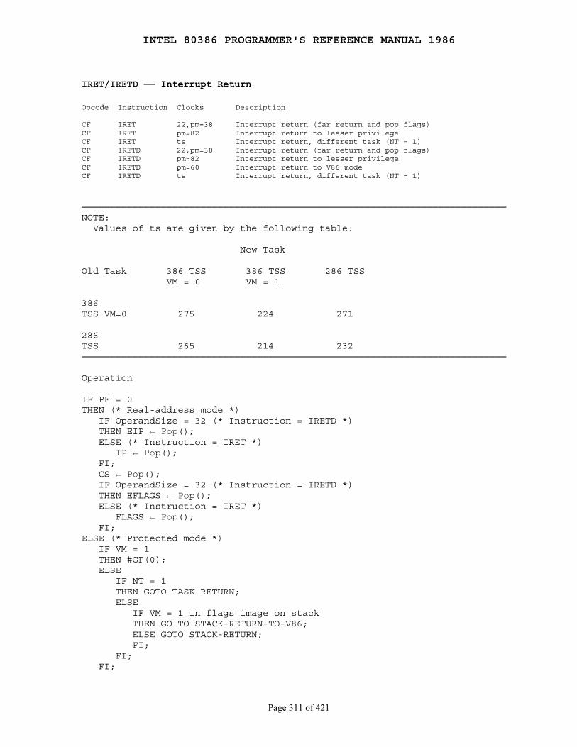
INTEL 80386 PROGRAMMER'S REFERENCE MANUAL 1986
Page 311 of 421
IRET/IRETD ── Interrupt Return
Opcode Instruction Clocks Description
CF IRET 22,pm=38 Interrupt return (far return and pop flags)CF IRET pm=82 Interrupt return to lesser privilegeCF IRET ts Interrupt return, different task (NT = 1)CF IRETD 22,pm=38 Interrupt return (far return and pop flags)CF IRETD pm=82 Interrupt return to lesser privilegeCF IRETD pm=60 Interrupt return to V86 modeCF IRETD ts Interrupt return, different task (NT = 1)
───────────────────────────────────────────────────────────────────────────NOTE: Values of ts are given by the following table:
New Task
Old Task 386 TSS 386 TSS 286 TSS VM = 0 VM = 1
386TSS VM=0 275 224 271
286TSS 265 214 232───────────────────────────────────────────────────────────────────────────
Operation
IF PE = 0THEN (* Real-address mode *) IF OperandSize = 32 (* Instruction = IRETD *) THEN EIP ← Pop(); ELSE (* Instruction = IRET *) IP ← Pop(); FI; CS ← Pop(); IF OperandSize = 32 (* Instruction = IRETD *) THEN EFLAGS ← Pop(); ELSE (* Instruction = IRET *) FLAGS ← Pop(); FI;ELSE (* Protected mode *) IF VM = 1 THEN #GP(0); ELSE IF NT = 1 THEN GOTO TASK-RETURN; ELSE IF VM = 1 in flags image on stack THEN GO TO STACK-RETURN-TO-V86; ELSE GOTO STACK-RETURN; FI; FI; FI;
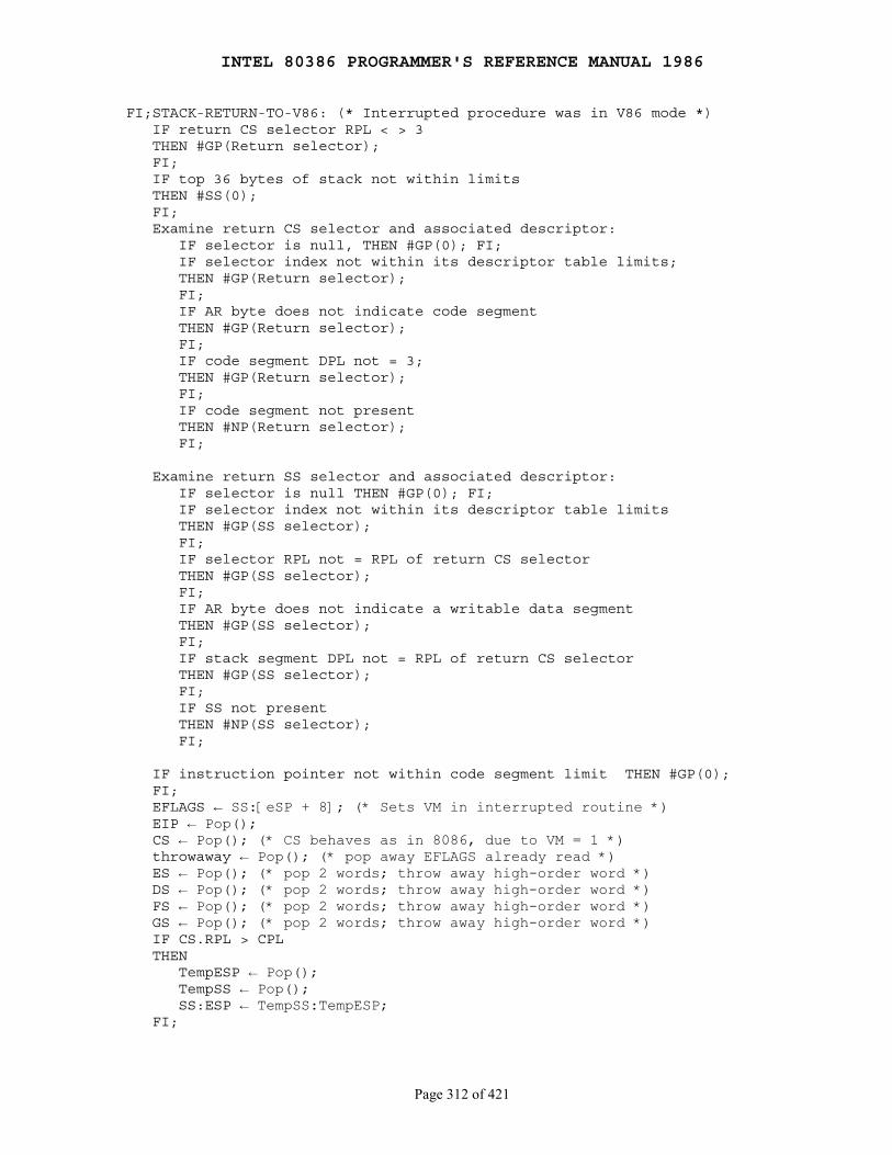
INTEL 80386 PROGRAMMER'S REFERENCE MANUAL 1986
Page 312 of 421
FI;STACK-RETURN-TO-V86: (* Interrupted procedure was in V86 mode *) IF return CS selector RPL < > 3 THEN #GP(Return selector); FI; IF top 36 bytes of stack not within limits THEN #SS(0); FI; Examine return CS selector and associated descriptor: IF selector is null, THEN #GP(0); FI; IF selector index not within its descriptor table limits; THEN #GP(Return selector); FI; IF AR byte does not indicate code segment THEN #GP(Return selector); FI; IF code segment DPL not = 3; THEN #GP(Return selector); FI; IF code segment not present THEN #NP(Return selector); FI;
Examine return SS selector and associated descriptor: IF selector is null THEN #GP(0); FI; IF selector index not within its descriptor table limits THEN #GP(SS selector); FI; IF selector RPL not = RPL of return CS selector THEN #GP(SS selector); FI; IF AR byte does not indicate a writable data segment THEN #GP(SS selector); FI; IF stack segment DPL not = RPL of return CS selector THEN #GP(SS selector); FI; IF SS not present THEN #NP(SS selector); FI;
IF instruction pointer not within code segment limit THEN #GP(0); FI; EFLAGS ← SS:[eSP + 8]; (* Sets VM in interrupted routine *) EIP ← Pop(); CS ← Pop(); (* CS behaves as in 8086, due to VM = 1 *) throwaway ← Pop(); (* pop away EFLAGS already read *) ES ← Pop(); (* pop 2 words; throw away high-order word *) DS ← Pop(); (* pop 2 words; throw away high-order word *) FS ← Pop(); (* pop 2 words; throw away high-order word *) GS ← Pop(); (* pop 2 words; throw away high-order word *) IF CS.RPL > CPL THEN TempESP ← Pop(); TempSS ← Pop(); SS:ESP ← TempSS:TempESP; FI;
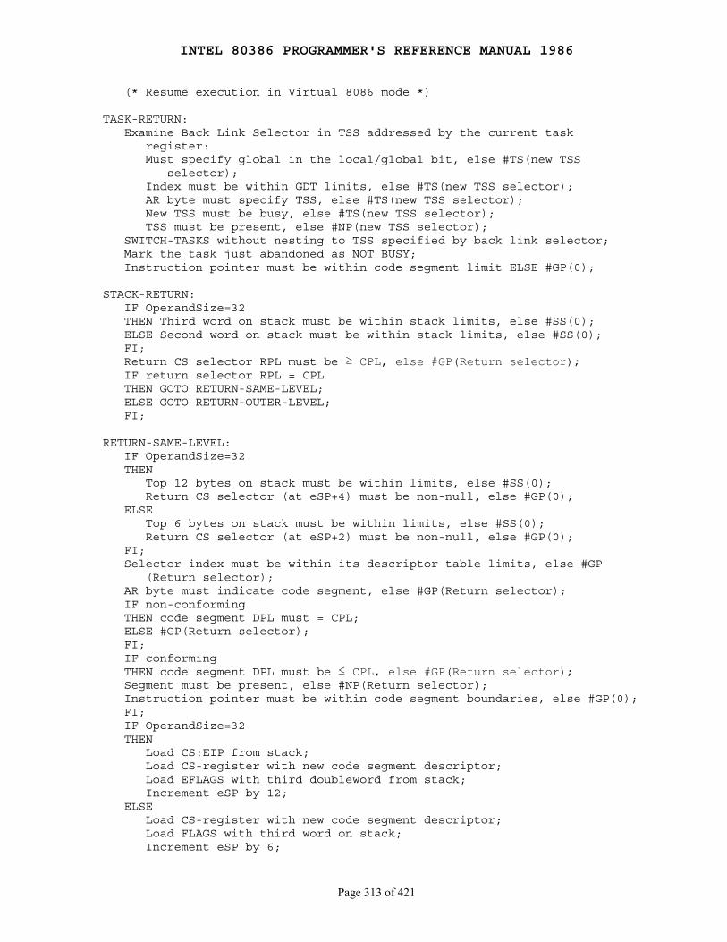
INTEL 80386 PROGRAMMER'S REFERENCE MANUAL 1986
Page 313 of 421
(* Resume execution in Virtual 8086 mode *)
TASK-RETURN: Examine Back Link Selector in TSS addressed by the current task register: Must specify global in the local/global bit, else #TS(new TSS selector); Index must be within GDT limits, else #TS(new TSS selector); AR byte must specify TSS, else #TS(new TSS selector); New TSS must be busy, else #TS(new TSS selector); TSS must be present, else #NP(new TSS selector); SWITCH-TASKS without nesting to TSS specified by back link selector; Mark the task just abandoned as NOT BUSY; Instruction pointer must be within code segment limit ELSE #GP(0);
STACK-RETURN: IF OperandSize=32 THEN Third word on stack must be within stack limits, else #SS(0); ELSE Second word on stack must be within stack limits, else #SS(0); FI; Return CS selector RPL must be ≥ CPL, else #GP(Return selector); IF return selector RPL = CPL THEN GOTO RETURN-SAME-LEVEL; ELSE GOTO RETURN-OUTER-LEVEL; FI;
RETURN-SAME-LEVEL: IF OperandSize=32 THEN Top 12 bytes on stack must be within limits, else #SS(0); Return CS selector (at eSP+4) must be non-null, else #GP(0); ELSE Top 6 bytes on stack must be within limits, else #SS(0); Return CS selector (at eSP+2) must be non-null, else #GP(0); FI; Selector index must be within its descriptor table limits, else #GP (Return selector); AR byte must indicate code segment, else #GP(Return selector); IF non-conforming THEN code segment DPL must = CPL; ELSE #GP(Return selector); FI; IF conforming THEN code segment DPL must be ≤ CPL, else #GP(Return selector); Segment must be present, else #NP(Return selector); Instruction pointer must be within code segment boundaries, else #GP(0); FI; IF OperandSize=32 THEN Load CS:EIP from stack; Load CS-register with new code segment descriptor; Load EFLAGS with third doubleword from stack; Increment eSP by 12; ELSE Load CS-register with new code segment descriptor; Load FLAGS with third word on stack; Increment eSP by 6;
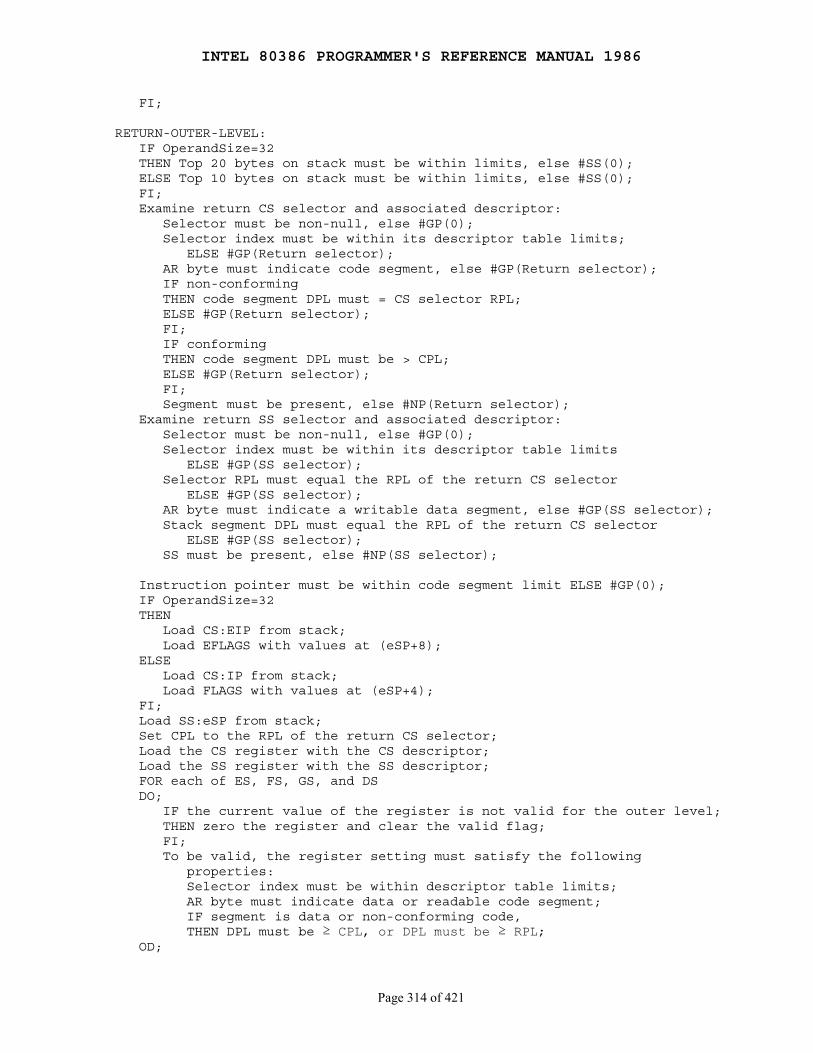
INTEL 80386 PROGRAMMER'S REFERENCE MANUAL 1986
Page 314 of 421
FI;
RETURN-OUTER-LEVEL: IF OperandSize=32 THEN Top 20 bytes on stack must be within limits, else #SS(0); ELSE Top 10 bytes on stack must be within limits, else #SS(0); FI; Examine return CS selector and associated descriptor: Selector must be non-null, else #GP(0); Selector index must be within its descriptor table limits; ELSE #GP(Return selector); AR byte must indicate code segment, else #GP(Return selector); IF non-conforming THEN code segment DPL must = CS selector RPL; ELSE #GP(Return selector); FI; IF conforming THEN code segment DPL must be > CPL; ELSE #GP(Return selector); FI; Segment must be present, else #NP(Return selector); Examine return SS selector and associated descriptor: Selector must be non-null, else #GP(0); Selector index must be within its descriptor table limits ELSE #GP(SS selector); Selector RPL must equal the RPL of the return CS selector ELSE #GP(SS selector); AR byte must indicate a writable data segment, else #GP(SS selector); Stack segment DPL must equal the RPL of the return CS selector ELSE #GP(SS selector); SS must be present, else #NP(SS selector);
Instruction pointer must be within code segment limit ELSE #GP(0); IF OperandSize=32 THEN Load CS:EIP from stack; Load EFLAGS with values at (eSP+8); ELSE Load CS:IP from stack; Load FLAGS with values at (eSP+4); FI; Load SS:eSP from stack; Set CPL to the RPL of the return CS selector; Load the CS register with the CS descriptor; Load the SS register with the SS descriptor; FOR each of ES, FS, GS, and DS DO; IF the current value of the register is not valid for the outer level; THEN zero the register and clear the valid flag; FI; To be valid, the register setting must satisfy the following properties: Selector index must be within descriptor table limits; AR byte must indicate data or readable code segment; IF segment is data or non-conforming code, THEN DPL must be ≥ CPL, or DPL must be ≥ RPL; OD;
INTEL 80386 PROGRAMMER'S REFERENCE MANUAL 1986
Page 315 of 421
Description
In Real Address Mode, IRET pops the instruction pointer, CS, and theflags register from the stack and resumes the interrupted routine.
In Protected Mode, the action of IRET depends on the setting of thenested task flag (NT) bit in the flag register. When popping the newflag image from the stack, the IOPL bits in the flag register are changedonly when CPL equals 0.
If NT equals 0, IRET returns from an interrupt procedure without atask switch. The code returned to must be equally or less privileged thanthe interrupt routine (as indicated by the RPL bits of the CS selectorpopped from the stack). If the destination code is less privileged, IRETalso pops the stack pointer and SS from the stack.
If NT equals 1, IRET reverses the operation of a CALL or INT thatcaused a task switch. The updated state of the task executing IRET issaved in its task state segment. If the task is reentered later, the codethat follows IRET is executed.
Flags Affected
All; the flags register is popped from stack
Protected Mode Exceptions
#GP, #NP, or #SS, as indicated under "Operation" above
Real Address Mode Exceptions
Interrupt 13 if any part of the operand being popped lies beyond address0FFFFH
Virtual 8086 Mode Exceptions
#GP(0) fault if IOPL is less than 3, to permit emulation
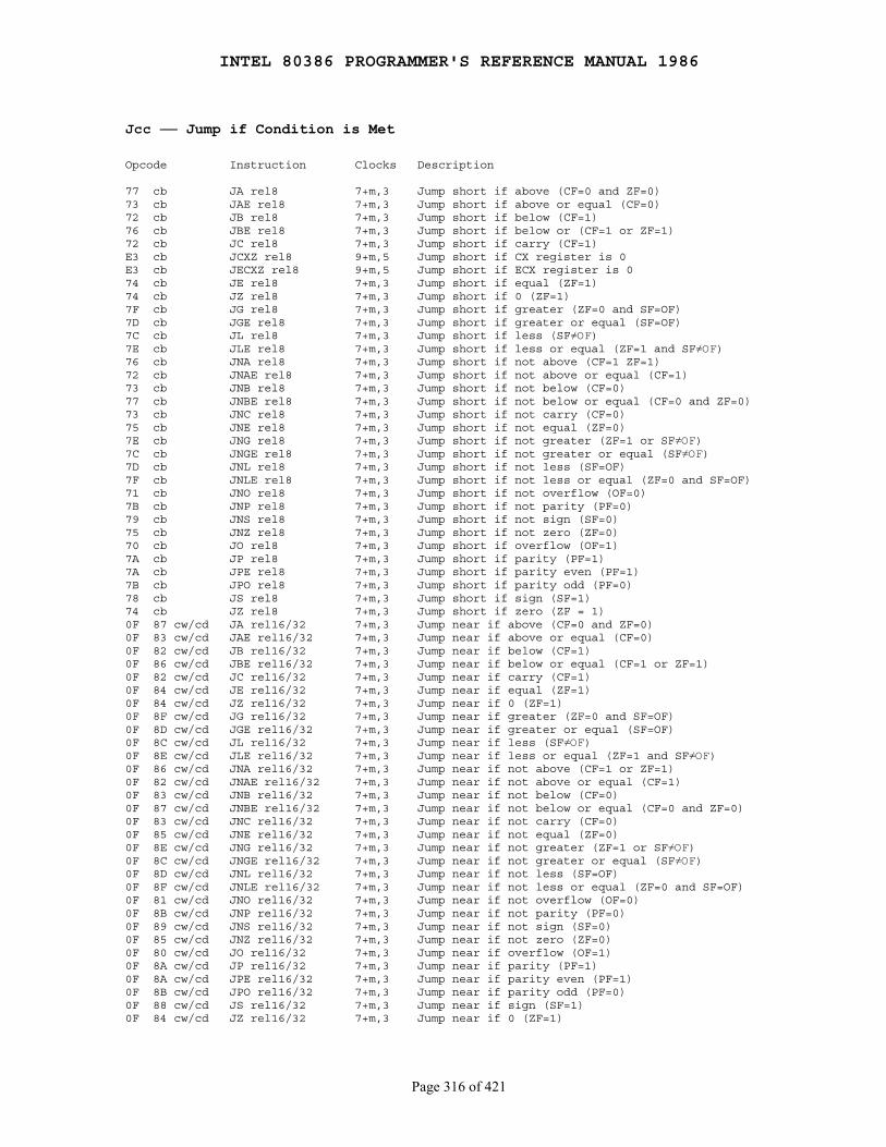
INTEL 80386 PROGRAMMER'S REFERENCE MANUAL 1986
Page 316 of 421
Jcc ── Jump if Condition is Met
Opcode Instruction Clocks Description
77 cb JA rel8 7+m,3 Jump short if above (CF=0 and ZF=0)73 cb JAE rel8 7+m,3 Jump short if above or equal (CF=0)72 cb JB rel8 7+m,3 Jump short if below (CF=1)76 cb JBE rel8 7+m,3 Jump short if below or (CF=1 or ZF=1)72 cb JC rel8 7+m,3 Jump short if carry (CF=1)E3 cb JCXZ rel8 9+m,5 Jump short if CX register is 0E3 cb JECXZ rel8 9+m,5 Jump short if ECX register is 074 cb JE rel8 7+m,3 Jump short if equal (ZF=1)74 cb JZ rel8 7+m,3 Jump short if 0 (ZF=1)7F cb JG rel8 7+m,3 Jump short if greater (ZF=0 and SF=OF)7D cb JGE rel8 7+m,3 Jump short if greater or equal (SF=OF)7C cb JL rel8 7+m,3 Jump short if less (SF≠OF)7E cb JLE rel8 7+m,3 Jump short if less or equal (ZF=1 and SF≠OF)76 cb JNA rel8 7+m,3 Jump short if not above (CF=1 ZF=1)72 cb JNAE rel8 7+m,3 Jump short if not above or equal (CF=1)73 cb JNB rel8 7+m,3 Jump short if not below (CF=0)77 cb JNBE rel8 7+m,3 Jump short if not below or equal (CF=0 and ZF=0)73 cb JNC rel8 7+m,3 Jump short if not carry (CF=0)75 cb JNE rel8 7+m,3 Jump short if not equal (ZF=0)7E cb JNG rel8 7+m,3 Jump short if not greater (ZF=1 or SF≠OF)7C cb JNGE rel8 7+m,3 Jump short if not greater or equal (SF≠OF)7D cb JNL rel8 7+m,3 Jump short if not less (SF=OF)7F cb JNLE rel8 7+m,3 Jump short if not less or equal (ZF=0 and SF=OF)71 cb JNO rel8 7+m,3 Jump short if not overflow (OF=0)7B cb JNP rel8 7+m,3 Jump short if not parity (PF=0)79 cb JNS rel8 7+m,3 Jump short if not sign (SF=0)75 cb JNZ rel8 7+m,3 Jump short if not zero (ZF=0)70 cb JO rel8 7+m,3 Jump short if overflow (OF=1)7A cb JP rel8 7+m,3 Jump short if parity (PF=1)7A cb JPE rel8 7+m,3 Jump short if parity even (PF=1)7B cb JPO rel8 7+m,3 Jump short if parity odd (PF=0)78 cb JS rel8 7+m,3 Jump short if sign (SF=1)74 cb JZ rel8 7+m,3 Jump short if zero (ZF = 1)0F 87 cw/cd JA rel16/32 7+m,3 Jump near if above (CF=0 and ZF=0)0F 83 cw/cd JAE rel16/32 7+m,3 Jump near if above or equal (CF=0)0F 82 cw/cd JB rel16/32 7+m,3 Jump near if below (CF=1)0F 86 cw/cd JBE rel16/32 7+m,3 Jump near if below or equal (CF=1 or ZF=1)0F 82 cw/cd JC rel16/32 7+m,3 Jump near if carry (CF=1)0F 84 cw/cd JE rel16/32 7+m,3 Jump near if equal (ZF=1)0F 84 cw/cd JZ rel16/32 7+m,3 Jump near if 0 (ZF=1)0F 8F cw/cd JG rel16/32 7+m,3 Jump near if greater (ZF=0 and SF=OF)0F 8D cw/cd JGE rel16/32 7+m,3 Jump near if greater or equal (SF=OF)0F 8C cw/cd JL rel16/32 7+m,3 Jump near if less (SF≠OF)0F 8E cw/cd JLE rel16/32 7+m,3 Jump near if less or equal (ZF=1 and SF≠OF)0F 86 cw/cd JNA rel16/32 7+m,3 Jump near if not above (CF=1 or ZF=1)0F 82 cw/cd JNAE rel16/32 7+m,3 Jump near if not above or equal (CF=1)0F 83 cw/cd JNB rel16/32 7+m,3 Jump near if not below (CF=0)0F 87 cw/cd JNBE rel16/32 7+m,3 Jump near if not below or equal (CF=0 and ZF=0)0F 83 cw/cd JNC rel16/32 7+m,3 Jump near if not carry (CF=0)0F 85 cw/cd JNE rel16/32 7+m,3 Jump near if not equal (ZF=0)0F 8E cw/cd JNG rel16/32 7+m,3 Jump near if not greater (ZF=1 or SF≠OF)0F 8C cw/cd JNGE rel16/32 7+m,3 Jump near if not greater or equal (SF≠OF)0F 8D cw/cd JNL rel16/32 7+m,3 Jump near if not less (SF=OF)0F 8F cw/cd JNLE rel16/32 7+m,3 Jump near if not less or equal (ZF=0 and SF=OF)0F 81 cw/cd JNO rel16/32 7+m,3 Jump near if not overflow (OF=0)0F 8B cw/cd JNP rel16/32 7+m,3 Jump near if not parity (PF=0)0F 89 cw/cd JNS rel16/32 7+m,3 Jump near if not sign (SF=0)0F 85 cw/cd JNZ rel16/32 7+m,3 Jump near if not zero (ZF=0)0F 80 cw/cd JO rel16/32 7+m,3 Jump near if overflow (OF=1)0F 8A cw/cd JP rel16/32 7+m,3 Jump near if parity (PF=1)0F 8A cw/cd JPE rel16/32 7+m,3 Jump near if parity even (PF=1)0F 8B cw/cd JPO rel16/32 7+m,3 Jump near if parity odd (PF=0)0F 88 cw/cd JS rel16/32 7+m,3 Jump near if sign (SF=1)0F 84 cw/cd JZ rel16/32 7+m,3 Jump near if 0 (ZF=1)
INTEL 80386 PROGRAMMER'S REFERENCE MANUAL 1986
Page 317 of 421
───────────────────────────────────────────────────────────────────────────NOTES: The first clock count is for the true condition (branch taken); the second clock count is for the false condition (branch not taken). rel16/32 indicates that these instructions map to two; one with a 16-bit relative displacement, the other with a 32-bit relative displacement, depending on the operand-size attribute of the instruction.───────────────────────────────────────────────────────────────────────────
Operation
IF conditionTHEN EIP ← EIP + SignExtend(rel8/16/32); IF OperandSize = 16 THEN EIP ← EIP AND 0000FFFFH; FI;FI;
Description
Conditional jumps (except JCXZ) test the flags which have been set bya previous instruction. The conditions for each mnemonic are given inparentheses after each description above. The terms "less" and "greater"are used for comparisons of signed integers; "above" and "below" areused for unsigned integers.
If the given condition is true, a jump is made to the location provided asthe operand. Instruction coding is most efficient when the target for theconditional jump is in the current code segment and within -128 to+127 bytes of the next instruction's first byte. The jump can also target-32768 thru +32767 (segment size attribute 16) or -231 thru +231-1(segment size attribute 32) relative to the next instruction's first byte.When the target for the conditional jump is in a different segment, usethe opposite case of the jump instruction (i.e., JE and JNE), and thenaccess the target with an unconditional far jump to the other segment.For example, you cannot code──
JZ FARLABEL;
You must instead code──
JNZ BEYOND; JMP FARLABEL;BEYOND:
Because there can be several ways to interpret a particular state of theflags, ASM386 provides more than one mnemonic for most of theconditional jump opcodes. For example, if you compared two characters inAX and want to jump if they are equal, use JE; or, if you ANDed AXwith a bit field mask and only want to jump if the result is 0, use JZ, asynonym for JE.
INTEL 80386 PROGRAMMER'S REFERENCE MANUAL 1986
Page 318 of 421
JCXZ differs from other conditional jumps because it tests the contents ofthe CX or ECX register for 0, not the flags. JCXZ is useful at the beginningof a conditional loop that terminates with a conditional loop instruction(such as LOOPNE TARGET LABEL. The JCXZ prevents entering the loop with CX orECX equal to zero, which would cause the loop to execute 64K or 32G timesinstead of zero times.
Flags Affected
None
Protected Mode Exceptions
#GP(0) if the offset jumped to is beyond the limits of the code segment
Real Address Mode Exceptions
None
Virtual 8086 Mode Exceptions
None
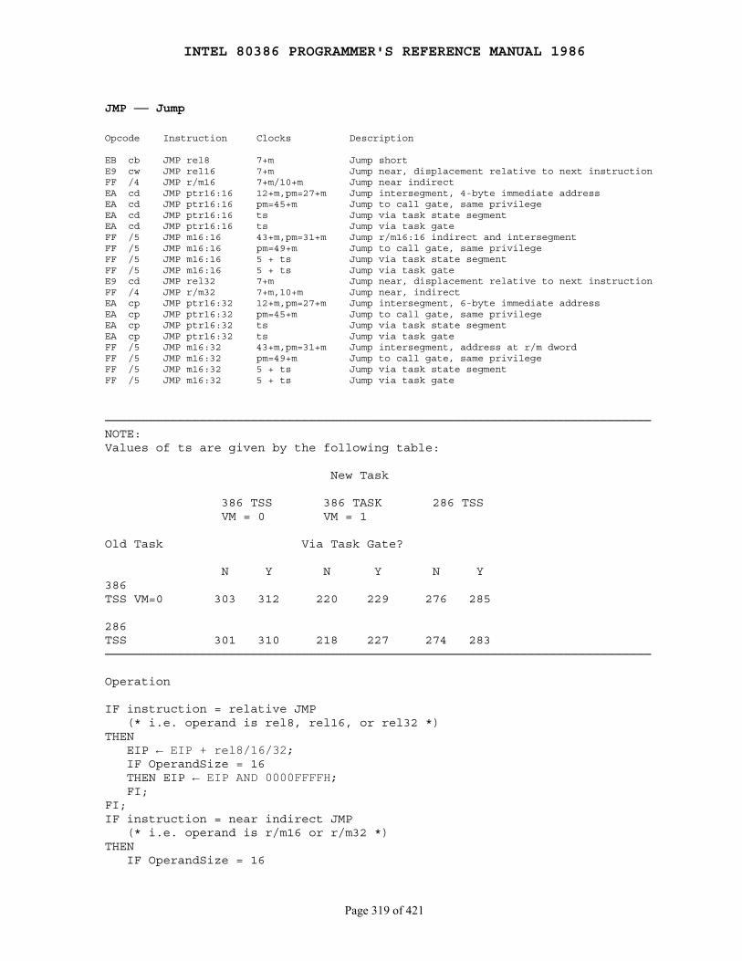
INTEL 80386 PROGRAMMER'S REFERENCE MANUAL 1986
Page 319 of 421
JMP ── Jump
Opcode Instruction Clocks Description
EB cb JMP rel8 7+m Jump shortE9 cw JMP rel16 7+m Jump near, displacement relative to next instructionFF /4 JMP r/m16 7+m/10+m Jump near indirectEA cd JMP ptr16:16 12+m,pm=27+m Jump intersegment, 4-byte immediate addressEA cd JMP ptr16:16 pm=45+m Jump to call gate, same privilegeEA cd JMP ptr16:16 ts Jump via task state segmentEA cd JMP ptr16:16 ts Jump via task gateFF /5 JMP m16:16 43+m,pm=31+m Jump r/m16:16 indirect and intersegmentFF /5 JMP m16:16 pm=49+m Jump to call gate, same privilegeFF /5 JMP m16:16 5 + ts Jump via task state segmentFF /5 JMP m16:16 5 + ts Jump via task gateE9 cd JMP rel32 7+m Jump near, displacement relative to next instructionFF /4 JMP r/m32 7+m,10+m Jump near, indirectEA cp JMP ptr16:32 12+m,pm=27+m Jump intersegment, 6-byte immediate addressEA cp JMP ptr16:32 pm=45+m Jump to call gate, same privilegeEA cp JMP ptr16:32 ts Jump via task state segmentEA cp JMP ptr16:32 ts Jump via task gateFF /5 JMP m16:32 43+m,pm=31+m Jump intersegment, address at r/m dwordFF /5 JMP m16:32 pm=49+m Jump to call gate, same privilegeFF /5 JMP m16:32 5 + ts Jump via task state segmentFF /5 JMP m16:32 5 + ts Jump via task gate
───────────────────────────────────────────────────────────────────────────NOTE:Values of ts are given by the following table:
New Task
386 TSS 386 TASK 286 TSS VM = 0 VM = 1
Old Task Via Task Gate?
N Y N Y N Y386TSS VM=0 303 312 220 229 276 285
286TSS 301 310 218 227 274 283───────────────────────────────────────────────────────────────────────────
Operation
IF instruction = relative JMP (* i.e. operand is rel8, rel16, or rel32 *)THEN EIP ← EIP + rel8/16/32; IF OperandSize = 16 THEN EIP ← EIP AND 0000FFFFH; FI;FI;IF instruction = near indirect JMP (* i.e. operand is r/m16 or r/m32 *)THEN IF OperandSize = 16
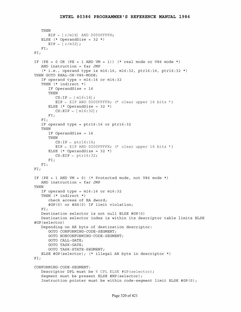
INTEL 80386 PROGRAMMER'S REFERENCE MANUAL 1986
Page 320 of 421
THEN EIP ← [r/m16] AND 0000FFFFH; ELSE (* OperandSize = 32 *) EIP ← [r/m32]; FI;FI;
IF (PE = 0 OR (PE = 1 AND VM = 1)) (* real mode or V86 mode *) AND instruction = far JMP (* i.e., operand type is m16:16, m16:32, ptr16:16, ptr16:32 *)THEN GOTO REAL-OR-V86-MODE; IF operand type = m16:16 or m16:32 THEN (* indirect *) IF OperandSize = 16 THEN CS:IP ← [m16:16]; EIP ← EIP AND 0000FFFFH; (* clear upper 16 bits *) ELSE (* OperandSize = 32 *) CS:EIP ← [m16:32]; FI; FI; IF operand type = ptr16:16 or ptr16:32 THEN IF OperandSize = 16 THEN CS:IP ← ptr16:16; EIP ← EIP AND 0000FFFFH; (* clear upper 16 bits *) ELSE (* OperandSize = 32 *) CS:EIP ← ptr16:32; FI; FI;FI;
IF (PE = 1 AND VM = 0) (* Protected mode, not V86 mode *) AND instruction = far JMPTHEN IF operand type = m16:16 or m16:32 THEN (* indirect *) check access of EA dword; #GP(0) or #SS(0) IF limit violation; FI; Destination selector is not null ELSE #GP(0) Destination selector index is within its descriptor table limits ELSE#GP(selector) Depending on AR byte of destination descriptor: GOTO CONFORMING-CODE-SEGMENT; GOTO NONCONFORMING-CODE-SEGMENT; GOTO CALL-GATE; GOTO TASK-GATE; GOTO TASK-STATE-SEGMENT; ELSE #GP(selector); (* illegal AR byte in descriptor *)FI;
CONFORMING-CODE-SEGMENT: Descriptor DPL must be ≤ CPL ELSE #GP(selector); Segment must be present ELSE #NP(selector); Instruction pointer must be within code-segment limit ELSE #GP(0);
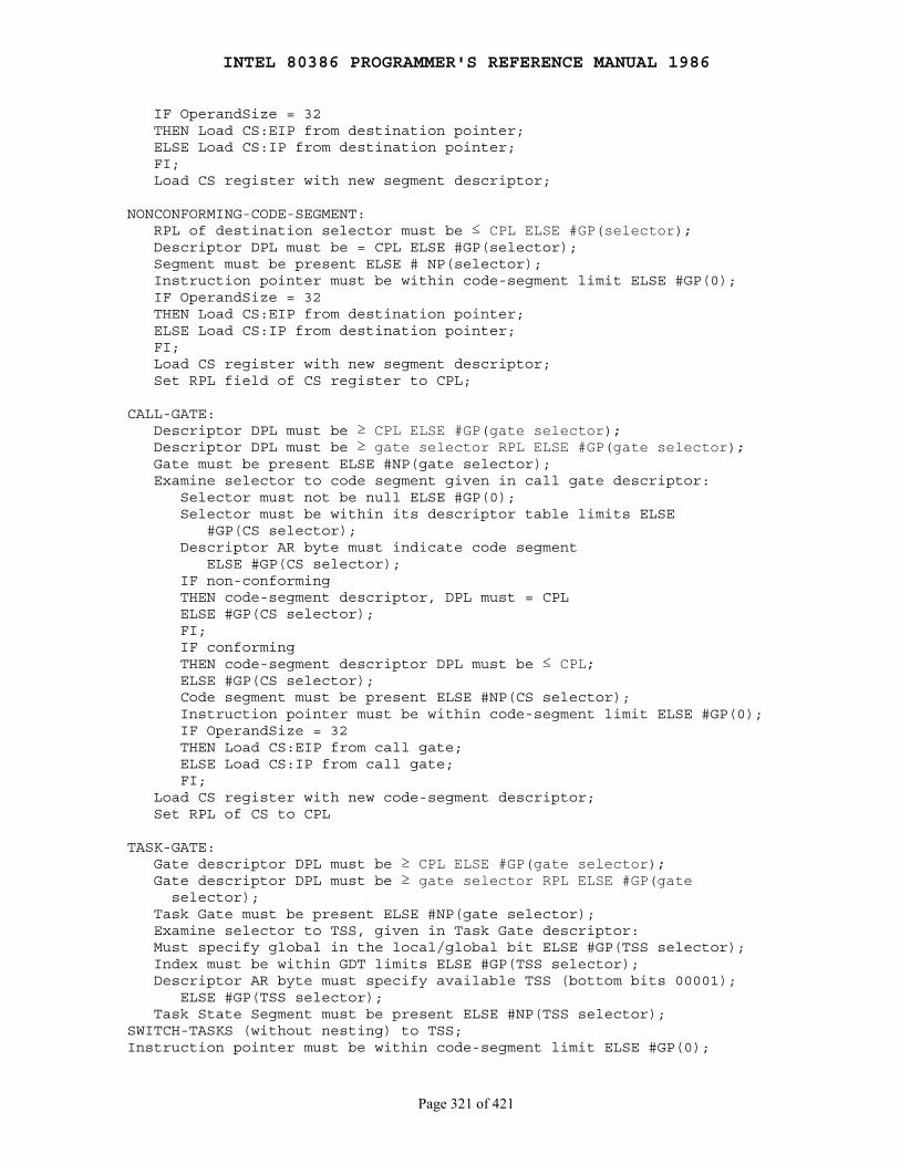
INTEL 80386 PROGRAMMER'S REFERENCE MANUAL 1986
Page 321 of 421
IF OperandSize = 32 THEN Load CS:EIP from destination pointer; ELSE Load CS:IP from destination pointer; FI; Load CS register with new segment descriptor;
NONCONFORMING-CODE-SEGMENT: RPL of destination selector must be ≤ CPL ELSE #GP(selector); Descriptor DPL must be = CPL ELSE #GP(selector); Segment must be present ELSE # NP(selector); Instruction pointer must be within code-segment limit ELSE #GP(0); IF OperandSize = 32 THEN Load CS:EIP from destination pointer; ELSE Load CS:IP from destination pointer; FI; Load CS register with new segment descriptor; Set RPL field of CS register to CPL;
CALL-GATE: Descriptor DPL must be ≥ CPL ELSE #GP(gate selector); Descriptor DPL must be ≥ gate selector RPL ELSE #GP(gate selector); Gate must be present ELSE #NP(gate selector); Examine selector to code segment given in call gate descriptor: Selector must not be null ELSE #GP(0); Selector must be within its descriptor table limits ELSE #GP(CS selector); Descriptor AR byte must indicate code segment ELSE #GP(CS selector); IF non-conforming THEN code-segment descriptor, DPL must = CPL ELSE #GP(CS selector); FI; IF conforming THEN code-segment descriptor DPL must be ≤ CPL; ELSE #GP(CS selector); Code segment must be present ELSE #NP(CS selector); Instruction pointer must be within code-segment limit ELSE #GP(0); IF OperandSize = 32 THEN Load CS:EIP from call gate; ELSE Load CS:IP from call gate; FI; Load CS register with new code-segment descriptor; Set RPL of CS to CPL
TASK-GATE: Gate descriptor DPL must be ≥ CPL ELSE #GP(gate selector); Gate descriptor DPL must be ≥ gate selector RPL ELSE #GP(gate selector); Task Gate must be present ELSE #NP(gate selector); Examine selector to TSS, given in Task Gate descriptor: Must specify global in the local/global bit ELSE #GP(TSS selector); Index must be within GDT limits ELSE #GP(TSS selector); Descriptor AR byte must specify available TSS (bottom bits 00001); ELSE #GP(TSS selector); Task State Segment must be present ELSE #NP(TSS selector);SWITCH-TASKS (without nesting) to TSS;Instruction pointer must be within code-segment limit ELSE #GP(0);
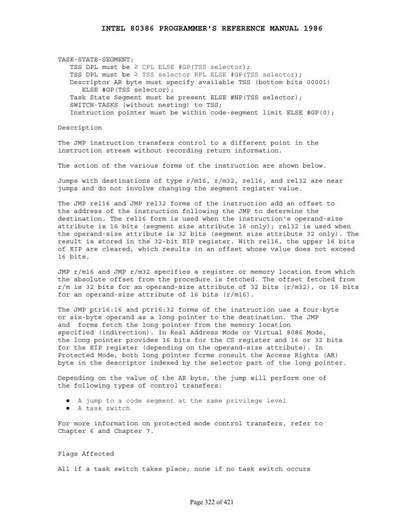
INTEL 80386 PROGRAMMER'S REFERENCE MANUAL 1986
Page 322 of 421
TASK-STATE-SEGMENT: TSS DPL must be ≥ CPL ELSE #GP(TSS selector); TSS DPL must be ≥ TSS selector RPL ELSE #GP(TSS selector); Descriptor AR byte must specify available TSS (bottom bits 00001) ELSE #GP(TSS selector); Task State Segment must be present ELSE #NP(TSS selector); SWITCH-TASKS (without nesting) to TSS; Instruction pointer must be within code-segment limit ELSE #GP(0);
Description
The JMP instruction transfers control to a different point in theinstruction stream without recording return information.
The action of the various forms of the instruction are shown below.
Jumps with destinations of type r/m16, r/m32, rel16, and rel32 are nearjumps and do not involve changing the segment register value.
The JMP rel16 and JMP rel32 forms of the instruction add an offset tothe address of the instruction following the JMP to determine thedestination. The rel16 form is used when the instruction's operand-sizeattribute is 16 bits (segment size attribute 16 only); rel32 is used whenthe operand-size attribute is 32 bits (segment size attribute 32 only). Theresult is stored in the 32-bit EIP register. With rel16, the upper 16 bitsof EIP are cleared, which results in an offset whose value does not exceed16 bits.
JMP r/m16 and JMP r/m32 specifies a register or memory location from whichthe absolute offset from the procedure is fetched. The offset fetched fromr/m is 32 bits for an operand-size attribute of 32 bits (r/m32), or 16 bitsfor an operand-size attribute of 16 bits (r/m16).
The JMP ptr16:16 and ptr16:32 forms of the instruction use a four-byteor six-byte operand as a long pointer to the destination. The JMPand forms fetch the long pointer from the memory locationspecified (indirection). In Real Address Mode or Virtual 8086 Mode,the long pointer provides 16 bits for the CS register and 16 or 32 bitsfor the EIP register (depending on the operand-size attribute). InProtected Mode, both long pointer forms consult the Access Rights (AR)byte in the descriptor indexed by the selector part of the long pointer.
Depending on the value of the AR byte, the jump will perform one ofthe following types of control transfers:
● A jump to a code segment at the same privilege level ● A task switch
For more information on protected mode control transfers, refer toChapter 6 and Chapter 7.
Flags Affected
All if a task switch takes place; none if no task switch occurs
INTEL 80386 PROGRAMMER'S REFERENCE MANUAL 1986
Page 323 of 421
Protected Mode Exceptions
Far jumps: #GP, #NP, #SS, and #TS, as indicated in the list above.
Near direct jumps: #GP(0) if procedure location is beyond the codesegment limits.
Near indirect jumps: #GP(0) for an illegal memory operand effectiveaddress in the CS, DS, ES, FS, or GS segments: #SS(0) for an illegaladdress in the SS segment; #GP if the indirect offset obtained is beyondthe code segment limits; #PF(fault-code) for a page fault.
Real Address Mode Exceptions
Interrupt 13 if any part of the operand would be outside of the effectiveaddress space from 0 to 0FFFFH
Virtual 8086 Mode Exceptions
Same exceptions as under Real Address Mode; #PF(fault-code) for apage fault
INTEL 80386 PROGRAMMER'S REFERENCE MANUAL 1986
Page 324 of 421
LAHF ── Load Flags into AH Register
Opcode Instruction Clocks Description
9F LAHF 2 Load: AH = flags SF ZF xx AF xx PF xx CF
Operation
AH ← SF:ZF:xx:AF:xx:PF:xx:CF;
Description
LAHF transfers the low byte of the flags word to AH. The bits, fromMSB to LSB, are sign, zero, indeterminate, auxiliary, carry,indeterminate, parity, indeterminate, and carry.
Flags Affected
None
Protected Mode Exceptions
None
Real Address Mode Exceptions
None
Virtual 8086 Mode Exceptions
None

INTEL 80386 PROGRAMMER'S REFERENCE MANUAL 1986
Page 325 of 421
LAR ── Load Access Rights Byte
Opcode Instruction Clocks Description
0F 02 /r LAR r16,r/m16 pm=15/16 r16 ← r/m16 masked by FF000F 02 /r LAR r32,r/m32 pm=15/16 r32 ← r/m32 masked by 00FxFF00
Description
The LAR instruction stores a marked form of the second doubleword ofthe descriptor for the source selector if the selector is visible at theCPL (modified by the selector's RPL) and is a valid descriptor type. Thedestination register is loaded with the high-order doubleword of thedescriptor masked by 00FxFF00, and ZF is set to 1. The x indicates that thefour bits corresponding to the upper four bits of the limit are undefined inthe value loaded by LAR. If the selector is invisible or of the wrong type,ZF is cleared.
If the 32-bit operand size is specified, the entire 32-bit value is loadedinto the 32-bit destination register. If the 16-bit operand size isspecified, the lower 16-bits of this value are stored in the 16-bitdestination register.
All code and data segment descriptors are valid for LAR.
The valid special segment and gate descriptor types for LAR are givenin the following table:
Type Name Valid/Invalid
0 Invalid Invalid 1 Available 80286 TSS Valid 2 LDT Valid 3 Busy 80286 TSS Valid 4 80286 call gate Valid 5 80286/80386 task gate Valid 6 80286 trap gate Valid 7 80286 interrupt gate Valid 8 Invalid Invalid 9 Available 80386 TSS Valid A Invalid Invalid B Busy 80386 TSS Valid C 80386 call gate Valid D Invalid Invalid E 80386 trap gate Valid F 80386 interrupt gate Valid
Flags Affected
ZF as described above
INTEL 80386 PROGRAMMER'S REFERENCE MANUAL 1986
Page 326 of 421
Protected Mode Exceptions
#GP(0) for an illegal memory operand effective address in the CS, DS,ES, FS, or GS segments; #SS(0) for an illegal address in the SS segment;#PF(fault-code) for a page fault
Real Address Mode Exceptions
Interrupt 6; LAR is unrecognized in Real Address Mode
Virtual 8086 Mode Exceptions
Same exceptions as in Real Address Mode
INTEL 80386 PROGRAMMER'S REFERENCE MANUAL 1986
Page 327 of 421
LEA ── Load Effective Address
Opcode Instruction Clocks Description
8D /r LEA r16,m 2 Store effective address for m in register r168D /r LEA r32,m 2 Store effective address for m in register r328D /r LEA r16,m 2 Store effective address for m in register r168D /r LEA r32,m 2 Store effective address for m in register r32
Operation
IF OperandSize = 16 AND AddressSize = 16THEN r16 ← Addr(m);ELSE IF OperandSize = 16 AND AddressSize = 32 THEN r16 ← Truncate_to_16bits(Addr(m)); (* 32-bit address *) ELSE IF OperandSize = 32 AND AddressSize = 16 THEN r32 ← Truncate_to_16bits(Addr(m)); ELSE IF OperandSize = 32 AND AddressSize = 32 THEN r32 ← Addr(m); FI; FI; FI;FI;
Description
LEA calculates the effective address (offset part) and stores it in thespecified register. The operand-size attribute of the instruction(represented by OperandSize in the algorithm under "Operation" above) isdetermined by the chosen register. The address-size attribute (representedby AddressSize) is determined by the USE attribute of the segment containingthe second operand. The address-size and operand-size attributes affect theaction performed by LEA, as follows:
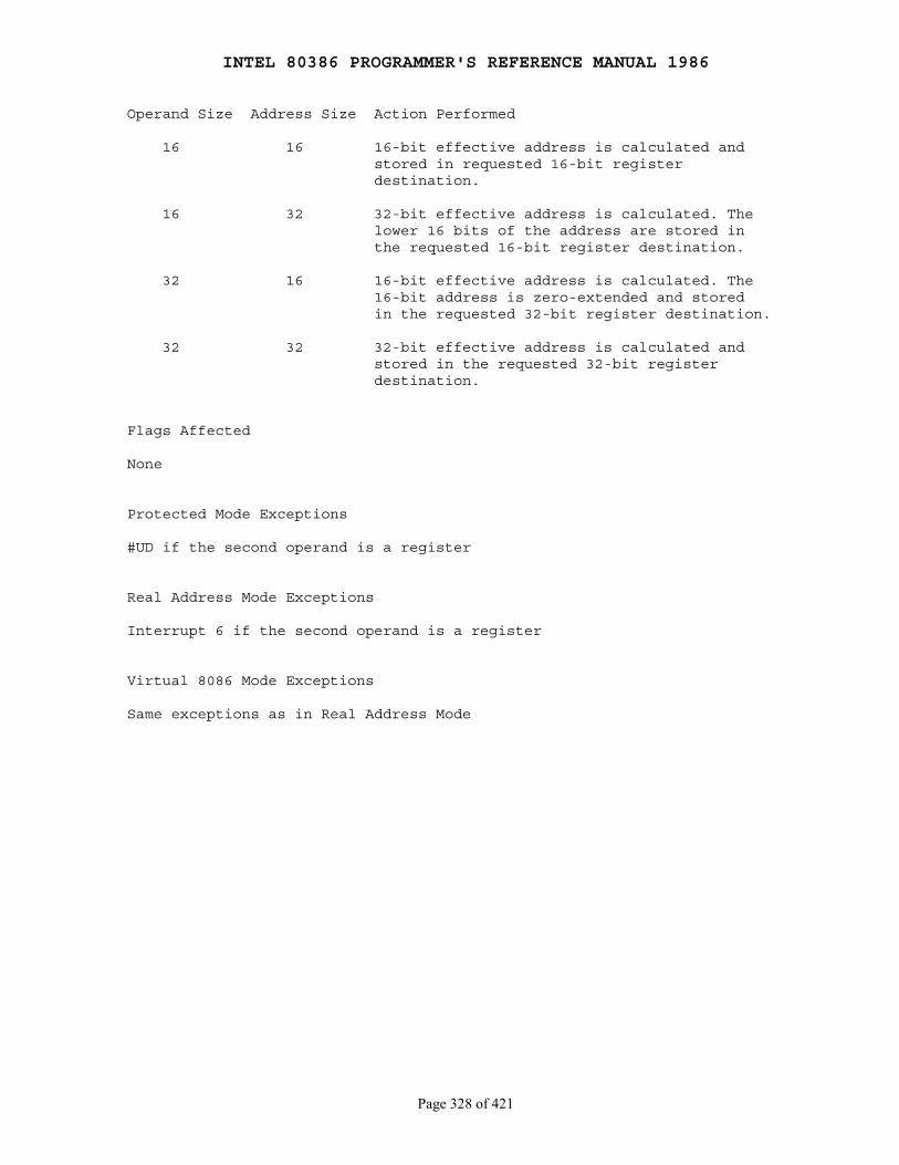
INTEL 80386 PROGRAMMER'S REFERENCE MANUAL 1986
Page 328 of 421
Operand Size Address Size Action Performed
16 16 16-bit effective address is calculated and stored in requested 16-bit register destination.
16 32 32-bit effective address is calculated. The lower 16 bits of the address are stored in the requested 16-bit register destination.
32 16 16-bit effective address is calculated. The 16-bit address is zero-extended and stored in the requested 32-bit register destination.
32 32 32-bit effective address is calculated and stored in the requested 32-bit register destination.
Flags Affected
None
Protected Mode Exceptions
#UD if the second operand is a register
Real Address Mode Exceptions
Interrupt 6 if the second operand is a register
Virtual 8086 Mode Exceptions
Same exceptions as in Real Address Mode
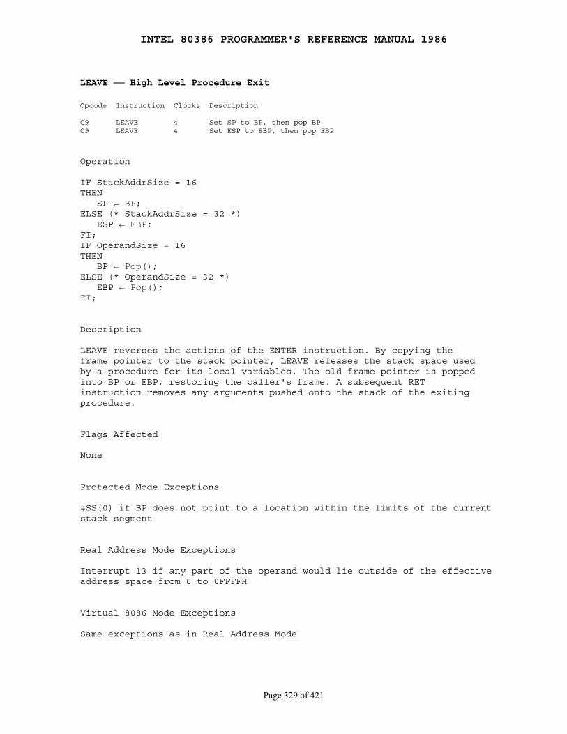
INTEL 80386 PROGRAMMER'S REFERENCE MANUAL 1986
Page 329 of 421
LEAVE ── High Level Procedure Exit
Opcode Instruction Clocks Description
C9 LEAVE 4 Set SP to BP, then pop BPC9 LEAVE 4 Set ESP to EBP, then pop EBP
Operation
IF StackAddrSize = 16THEN SP ← BP;ELSE (* StackAddrSize = 32 *) ESP ← EBP;FI;IF OperandSize = 16THEN BP ← Pop();ELSE (* OperandSize = 32 *) EBP ← Pop();FI;
Description
LEAVE reverses the actions of the ENTER instruction. By copying theframe pointer to the stack pointer, LEAVE releases the stack space usedby a procedure for its local variables. The old frame pointer is poppedinto BP or EBP, restoring the caller's frame. A subsequent RETinstruction removes any arguments pushed onto the stack of the exitingprocedure.
Flags Affected
None
Protected Mode Exceptions
#SS(0) if BP does not point to a location within the limits of the currentstack segment
Real Address Mode Exceptions
Interrupt 13 if any part of the operand would lie outside of the effectiveaddress space from 0 to 0FFFFH
Virtual 8086 Mode Exceptions
Same exceptions as in Real Address Mode
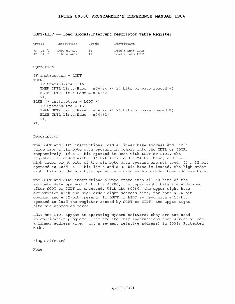
INTEL 80386 PROGRAMMER'S REFERENCE MANUAL 1986
Page 330 of 421
LGDT/LIDT ── Load Global/Interrupt Descriptor Table Register
Opcode Instruction Clocks Description
0F 01 /2 LGDT m16&32 11 Load m into GDTR0F 01 /3 LIDT m16&32 11 Load m into IDTR
Operation
IF instruction = LIDTTHEN IF OperandSize = 16 THEN IDTR.Limit:Base ← m16:24 (* 24 bits of base loaded *) ELSE IDTR.Limit:Base ← m16:32 FI;ELSE (* instruction = LGDT *) IF OperandSize = 16 THEN GDTR.Limit:Base ← m16:24 (* 24 bits of base loaded *) ELSE GDTR.Limit:Base ← m16:32; FI;FI;
Description
The LGDT and LIDT instructions load a linear base address and limitvalue from a six-byte data operand in memory into the GDTR or IDTR,respectively. If a 16-bit operand is used with LGDT or LIDT, theregister is loaded with a 16-bit limit and a 24-bit base, and thehigh-order eight bits of the six-byte data operand are not used. If a 32-bitoperand is used, a 16-bit limit and a 32-bit base is loaded; the high-ordereight bits of the six-byte operand are used as high-order base address bits.
The SGDT and SIDT instructions always store into all 48 bits of thesix-byte data operand. With the 80286, the upper eight bits are undefinedafter SGDT or SIDT is executed. With the 80386, the upper eight bitsare written with the high-order eight address bits, for both a 16-bitoperand and a 32-bit operand. If LGDT or LIDT is used with a 16-bitoperand to load the register stored by SGDT or SIDT, the upper eightbits are stored as zeros.
LGDT and LIDT appear in operating system software; they are not usedin application programs. They are the only instructions that directly loada linear address (i.e., not a segment relative address) in 80386 ProtectedMode.
Flags Affected
None
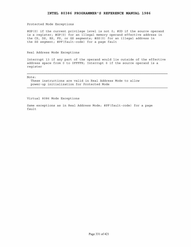
INTEL 80386 PROGRAMMER'S REFERENCE MANUAL 1986
Page 331 of 421
Protected Mode Exceptions
#GP(0) if the current privilege level is not 0; #UD if the source operandis a register; #GP(0) for an illegal memory operand effective address inthe CS, DS, ES, FS, or GS segments; #SS(0) for an illegal address inthe SS segment; #PF(fault-code) for a page fault
Real Address Mode Exceptions
Interrupt 13 if any part of the operand would lie outside of the effectiveaddress space from 0 to 0FFFFH; Interrupt 6 if the source operand is aregister
───────────────────────────────────────────────────────────────────────────Note: These instructions are valid in Real Address Mode to allow power-up initialization for Protected Mode───────────────────────────────────────────────────────────────────────────
Virtual 8086 Mode Exceptions
Same exceptions as in Real Address Mode; #PF(fault-code) for a pagefault
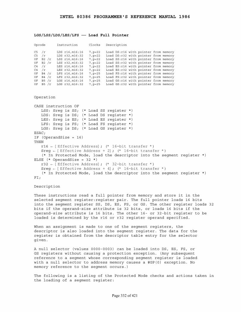
INTEL 80386 PROGRAMMER'S REFERENCE MANUAL 1986
Page 332 of 421
LGS/LSS/LDS/LES/LFS ── Load Full Pointer
Opcode Instruction Clocks Description
C5 /r LDS r16,m16:16 7,p=22 Load DS:r16 with pointer from memoryC5 /r LDS r32,m16:32 7,p=22 Load DS:r32 with pointer from memory0F B2 /r LSS r16,m16:16 7,p=22 Load SS:r16 with pointer from memory0F B2 /r LSS r32,m16:32 7,p=22 Load SS:r32 with pointer from memoryC4 /r LES r16,m16:16 7,p=22 Load ES:r16 with pointer from memoryC4 /r LES r32,m16:32 7,p=22 Load ES:r32 with pointer from memory0F B4 /r LFS r16,m16:16 7,p=25 Load FS:r16 with pointer from memory0F B4 /r LFS r32,m16:32 7,p=25 Load FS:r32 with pointer from memory0F B5 /r LGS r16,m16:16 7,p=25 Load GS:r16 with pointer from memory0F B5 /r LGS r32,m16:32 7,p=25 Load GS:r32 with pointer from memory
Operation
CASE instruction OF LSS: Sreg is SS; (* Load SS register *) LDS: Sreg is DS; (* Load DS register *) LES: Sreg is ES; (* Load ES register *) LFS: Sreg is FS; (* Load FS register *) LGS: Sreg is DS; (* Load GS register *)ESAC;IF (OperandSize = 16)THEN r16 ← [Effective Address]; (* 16-bit transfer *) Sreg ← [Effective Address + 2]; (* 16-bit transfer *) (* In Protected Mode, load the descriptor into the segment register *)ELSE (* OperandSize = 32 *) r32 ← [Effective Address]; (* 32-bit transfer *) Sreg ← [Effective Address + 4]; (* 16-bit transfer *) (* In Protected Mode, load the descriptor into the segment register *)FI;
Description
These instructions read a full pointer from memory and store it in theselected segment register:register pair. The full pointer loads 16 bitsinto the segment register SS, DS, ES, FS, or GS. The other register loads 32bits if the operand-size attribute is 32 bits, or loads 16 bits if theoperand-size attribute is 16 bits. The other 16- or 32-bit register to beloaded is determined by the r16 or r32 register operand specified.
When an assignment is made to one of the segment registers, thedescriptor is also loaded into the segment register. The data for theregister is obtained from the descriptor table entry for the selectorgiven.
A null selector (values 0000-0003) can be loaded into DS, ES, FS, orGS registers without causing a protection exception. (Any subsequentreference to a segment whose corresponding segment register is loadedwith a null selector to address memory causes a #GP(0) exception. Nomemory reference to the segment occurs.)
The following is a listing of the Protected Mode checks and actions taken inthe loading of a segment register:
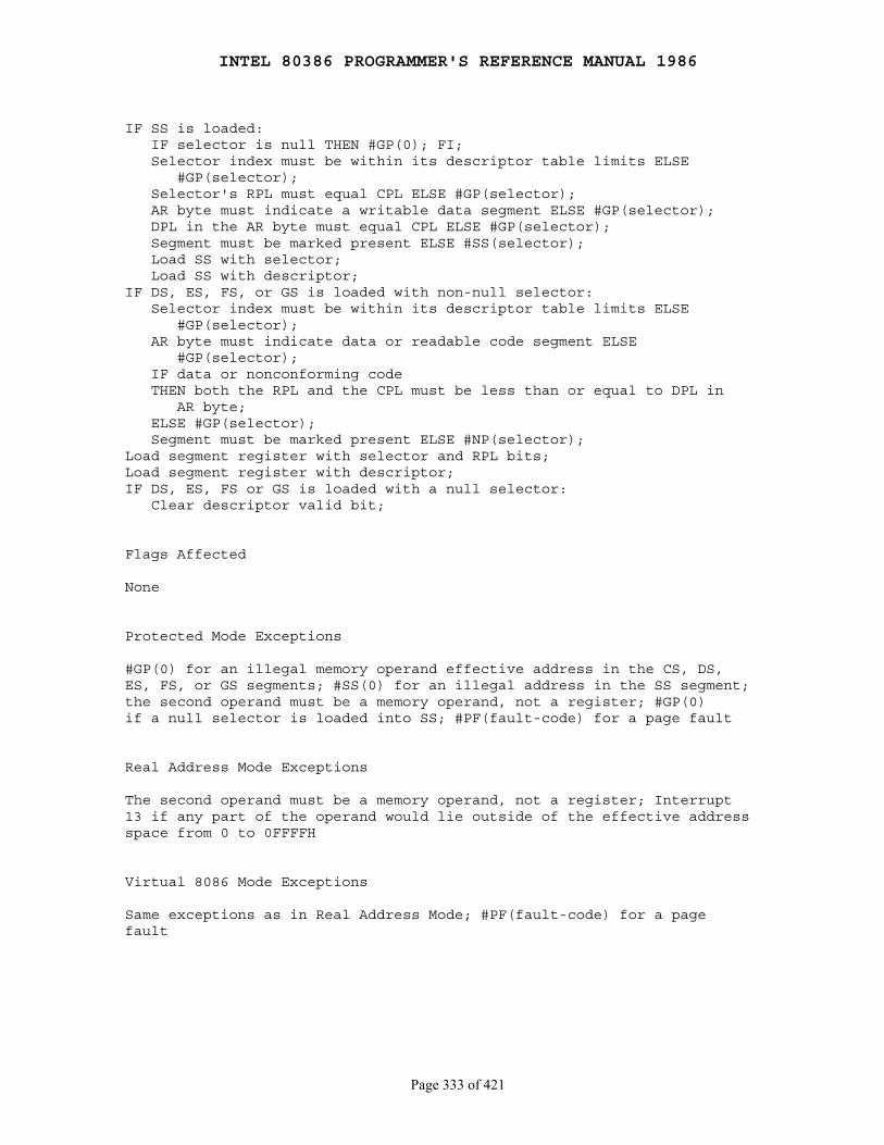
INTEL 80386 PROGRAMMER'S REFERENCE MANUAL 1986
Page 333 of 421
IF SS is loaded: IF selector is null THEN #GP(0); FI; Selector index must be within its descriptor table limits ELSE #GP(selector); Selector's RPL must equal CPL ELSE #GP(selector); AR byte must indicate a writable data segment ELSE #GP(selector); DPL in the AR byte must equal CPL ELSE #GP(selector); Segment must be marked present ELSE #SS(selector); Load SS with selector; Load SS with descriptor;IF DS, ES, FS, or GS is loaded with non-null selector: Selector index must be within its descriptor table limits ELSE #GP(selector); AR byte must indicate data or readable code segment ELSE #GP(selector); IF data or nonconforming code THEN both the RPL and the CPL must be less than or equal to DPL in AR byte; ELSE #GP(selector); Segment must be marked present ELSE #NP(selector);Load segment register with selector and RPL bits;Load segment register with descriptor;IF DS, ES, FS or GS is loaded with a null selector: Clear descriptor valid bit;
Flags Affected
None
Protected Mode Exceptions
#GP(0) for an illegal memory operand effective address in the CS, DS,ES, FS, or GS segments; #SS(0) for an illegal address in the SS segment;the second operand must be a memory operand, not a register; #GP(0)if a null selector is loaded into SS; #PF(fault-code) for a page fault
Real Address Mode Exceptions
The second operand must be a memory operand, not a register; Interrupt13 if any part of the operand would lie outside of the effective addressspace from 0 to 0FFFFH
Virtual 8086 Mode Exceptions
Same exceptions as in Real Address Mode; #PF(fault-code) for a pagefault
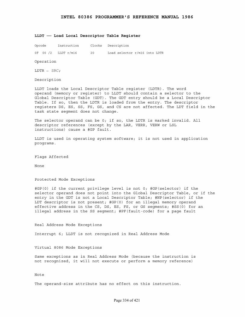
INTEL 80386 PROGRAMMER'S REFERENCE MANUAL 1986
Page 334 of 421
LLDT ── Load Local Descriptor Table Register
Opcode Instruction Clocks Description
0F 00 /2 LLDT r/m16 20 Load selector r/m16 into LDTR
Operation
LDTR ← SRC;
Description
LLDT loads the Local Descriptor Table register (LDTR). The wordoperand (memory or register) to LLDT should contain a selector to theGlobal Descriptor Table (GDT). The GDT entry should be a Local DescriptorTable. If so, then the LDTR is loaded from the entry. The descriptorregisters DS, ES, SS, FS, GS, and CS are not affected. The LDT field in thetask state segment does not change.
The selector operand can be 0; if so, the LDTR is marked invalid. Alldescriptor references (except by the LAR, VERR, VERW or LSLinstructions) cause a #GP fault.
LLDT is used in operating system software; it is not used in applicationprograms.
Flags Affected
None
Protected Mode Exceptions
#GP(0) if the current privilege level is not 0; #GP(selector) if theselector operand does not point into the Global Descriptor Table, or if theentry in the GDT is not a Local Descriptor Table; #NP(selector) if theLDT descriptor is not present; #GP(0) for an illegal memory operandeffective address in the CS, DS, ES, FS, or GS segments; #SS(0) for anillegal address in the SS segment; #PF(fault-code) for a page fault
Real Address Mode Exceptions
Interrupt 6; LLDT is not recognized in Real Address Mode
Virtual 8086 Mode Exceptions
Same exceptions as in Real Address Mode (because the instruction isnot recognized, it will not execute or perform a memory reference)
Note
The operand-size attribute has no effect on this instruction.
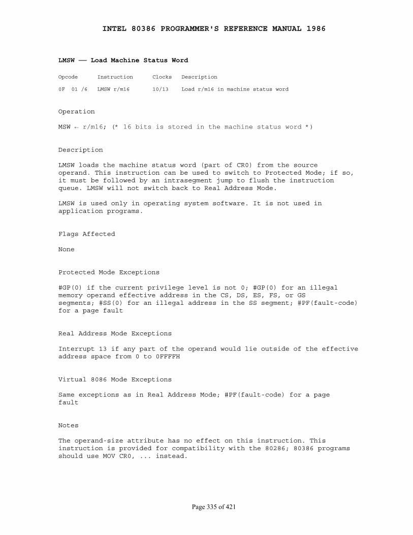
INTEL 80386 PROGRAMMER'S REFERENCE MANUAL 1986
Page 335 of 421
LMSW ── Load Machine Status Word
Opcode Instruction Clocks Description
0F 01 /6 LMSW r/m16 10/13 Load r/m16 in machine status word
Operation
MSW ← r/m16; (* 16 bits is stored in the machine status word *)
Description
LMSW loads the machine status word (part of CR0) from the sourceoperand. This instruction can be used to switch to Protected Mode; if so,it must be followed by an intrasegment jump to flush the instructionqueue. LMSW will not switch back to Real Address Mode.
LMSW is used only in operating system software. It is not used inapplication programs.
Flags Affected
None
Protected Mode Exceptions
#GP(0) if the current privilege level is not 0; #GP(0) for an illegalmemory operand effective address in the CS, DS, ES, FS, or GSsegments; #SS(0) for an illegal address in the SS segment; #PF(fault-code)for a page fault
Real Address Mode Exceptions
Interrupt 13 if any part of the operand would lie outside of the effectiveaddress space from 0 to 0FFFFH
Virtual 8086 Mode Exceptions
Same exceptions as in Real Address Mode; #PF(fault-code) for a pagefault
Notes
The operand-size attribute has no effect on this instruction. Thisinstruction is provided for compatibility with the 80286; 80386 programsshould use MOV CR0, ... instead.
INTEL 80386 PROGRAMMER'S REFERENCE MANUAL 1986
Page 336 of 421
LOCK ── Assert LOCK# Signal Prefix
Opcode Instruction Clocks Description
F0 LOCK 0 Assert LOCK# signal for the next instruction
Description
The LOCK prefix causes the LOCK# signal of the 80386 to be assertedduring execution of the instruction that follows it. In a multiprocessorenvironment, this signal can be used to ensure that the 80386 hasexclusive use of any shared memory while LOCK# is asserted. Theread-modify-write sequence typically used to implement test-and-set on the80386 is the BTS instruction.
The LOCK prefix functions only with the following instructions:
BT, BTS, BTR, BTC mem, reg/immXCHG reg, memXCHG mem, regADD, OR, ADC, SBB, AND, SUB, XOR mem, reg/immNOT, NEG, INC, DEC mem
An undefined opcode trap will be generated if a LOCK prefix is usedwith any instruction not listed above.
XCHG always asserts LOCK# regardless of the presence or absence ofthe LOCK prefix.
The integrity of the LOCK is not affected by the alignment of thememory field. Memory locking is observed for arbitrarily misalignedfields.
Locked access is not assured if another 80386 processor is executing aninstruction concurrently that has one of the following characteristics:
● Is not preceded by a LOCK prefix
● Is not one of the instructions in the preceding list
● Specifies a memory operand that does not exactly overlap the destination operand. Locking is not guaranteed for partial overlap, even if one memory operand is wholly contained within another.
Flags Affected
None
Protected Mode Exceptions
#UD if LOCK is used with an instruction not listed in the "Description"section above; other exceptions can be generated by the subsequent(locked) instruction
INTEL 80386 PROGRAMMER'S REFERENCE MANUAL 1986
Page 337 of 421
Real Address Mode Exceptions
Interrupt 6 if LOCK is used with an instruction not listed in the"Description" section above; exceptions can still be generated by thesubsequent (locked) instruction
Virtual 8086 Mode Exceptions
#UD if LOCK is used with an instruction not listed in the "Description"section above; exceptions can still be generated by the subsequent (locked)instruction
INTEL 80386 PROGRAMMER'S REFERENCE MANUAL 1986
Page 338 of 421
LODS/LODSB/LODSW/LODSD ── Load String Operand
Opcode Instruction Clocks Description
AC LODS m8 5 Load byte [(E)SI] into ALAD LODS m16 5 Load word [(E)SI] into AXAD LODS m32 5 Load dword [(E)SI] into EAXAC LODSB 5 Load byte DS:[(E)SI] into ALAD LODSW 5 Load word DS:[(E)SI] into AXAD LODSD 5 Load dword DS:[(E)SI] into EAX
Operation
IF AddressSize = 16THEN use SI for source-indexELSE (* AddressSize = 32 *) use ESI for source-index;FI;IF byte type of instructionTHEN AL ← [source-index]; (* byte load *) IF DF = 0 THEN IncDec ← 1 ELSE IncDec ← -1; FI;ELSE IF OperandSize = 16 THEN AX ← [source-index]; (* word load *) IF DF = 0 THEN IncDec ← 2 ELSE IncDec ← -2; FI; ELSE (* OperandSize = 32 *) EAX ← [source-index]; (* dword load *) IF DF = 0 THEN IncDec ← 4 ELSE IncDec ← -4; FI; FI;FI;source-index ← source-index + IncDec
Description
LODS loads the AL, AX, or EAX register with the memory byte, word,or doubleword at the location pointed to by the source-index register.After the transfer is made, the source-index register is automaticallyadvanced. If the direction flag is 0 (CLD was executed), the source indexincrements; if the direction flag is 1 (STD was executed), it decrements.The increment or decrement is 1 if a byte is loaded, 2 if a word is loaded,or 4 if a doubleword is loaded.
If the address-size attribute for this instruction is 16 bits, SI is usedfor the source-index register; otherwise the address-size attribute is 32bits, and the ESI register is used. The address of the source data isdetermined solely by the contents of ESI/SI. Load the correct index valueinto SI before executing the LODS instruction. LODSB, LODSW, LODSD aresynonyms for the byte, word, and doubleword LODS instructions.
LODS can be preceded by the REP prefix; however, LODS is used more typicallywithin a LOOP construct, because further processing of the data moved intoEAX, AX, or AL is usually necessary.
INTEL 80386 PROGRAMMER'S REFERENCE MANUAL 1986
Page 339 of 421
Flags Affected
None
Protected Mode Exceptions
#GP(0) for an illegal memory operand effective address in the CS, DS,ES, FS, or GS segments; #SS(0) for an illegal address in the SS segment;#PF(fault-code) for a page fault
Real Address Mode Exceptions
Interrupt 13 if any part of the operand would lie outside of the effectiveaddress space from 0 to 0FFFFH
Virtual 8086 Mode Exceptions
Same exceptions as in Real Address Mode; #PF(fault-code) for a pagefault

INTEL 80386 PROGRAMMER'S REFERENCE MANUAL 1986
Page 340 of 421
LOOP/LOOPcond ── Loop Control with CX Counter
Opcode Instruction Clocks Description
E2 cb LOOP rel8 11+m DEC count; jump short if count ≠ 0E1 cb LOOPE rel8 11+m DEC count; jump short if count ≠ 0 and ZF=1E1 cb LOOPZ rel8 11+m DEC count; jump short if count ≠ 0 and ZF=1E0 cb LOOPNE rel8 11+m DEC count; jump short if count ≠ 0 and ZF=0E0 cb LOOPNZ rel8 11+m DEC count; jump short if count ≠ 0 and ZF=0
Operation
IF AddressSize = 16 THEN CountReg is CX ELSE CountReg is ECX; FI;CountReg ← CountReg - 1;IF instruction ≠ LOOPTHEN IF (instruction = LOOPE) OR (instruction = LOOPZ) THEN BranchCond ← (ZF = 1) AND (CountReg ≠ 0); FI; IF (instruction = LOOPNE) OR (instruction = LOOPNZ) THEN BranchCond ← (ZF = 0) AND (CountReg ≠ 0); FI;FI;
IF BranchCondTHEN IF OperandSize = 16 THEN IP ← IP + SignExtend(rel8); ELSE (* OperandSize = 32 *) EIP ← EIP + SignExtend(rel8); FI;FI;
Description
LOOP decrements the count register without changing any of the flags.Conditions are then checked for the form of LOOP being used. If theconditions are met, a short jump is made to the label given by the operandto LOOP. If the address-size attribute is 16 bits, the CX register is usedas the count register; otherwise the ECX register is used. The operandof LOOP must be in the range from 128 (decimal) bytes before theinstruction to 127 bytes ahead of the instruction.
The LOOP instructions provide iteration control and combine loop indexmanagement with conditional branching. Use the LOOP instruction byloading an unsigned iteration count into the count register, then code theLOOP at the end of a series of instructions to be iterated. Thedestination of LOOP is a label that points to the beginning of theiteration.
INTEL 80386 PROGRAMMER'S REFERENCE MANUAL 1986
Page 341 of 421
Flags Affected
None
Protected Mode Exceptions
#GP(0) if the offset jumped to is beyond the limits of the current codesegment
Real Address Mode Exceptions
None
Virtual 8086 Mode Exceptions
None

INTEL 80386 PROGRAMMER'S REFERENCE MANUAL 1986
Page 342 of 421
LSL ── Load Segment Limit
Opcode Instruction Clocks Description
0F 03 /r LSL r16,r/m16 pm=20/21 Load: r16 ← segment limit, selector r/m16 (byte granular)0F 03 /r LSL r32,r/m32 pm=20/21 Load: r32 ← segment limit, selector r/m32 (byte granular)0F 03 /r LSL r16,r/m16 pm=25/26 Load: r16 ← segment limit, selector r/m16 (page granular)0F 03 /r LSL r32,r/m32 pm=25/26 Load: r32 ← segment limit, selector r/m32 (page granular)
Description
The LSL instruction loads a register with an unscrambled segment limit,and sets ZF to 1, provided that the source selector is visible at the CPLweakened by RPL, and that the descriptor is a type accepted by LSL.Otherwise, ZF is cleared to 0, and the destination register is unchanged.The segment limit is loaded as a byte granular value. If the descriptorhas a page granular segment limit, LSL will translate it to a byte limitbefore loading it in the destination register (shift left 12 the 20-bit"raw" limit from descriptor, then OR with 00000FFFH).
The 32-bit forms of this instruction store the 32-bit byte granular limitin the 16-bit destination register.
Code and data segment descriptors are valid for LSL.
The valid special segment and gate descriptor types for LSL are givenin the following table:
Type Name Valid/Invalid
0 Invalid Invalid 1 Available 80286 TSS Valid 2 LDT Valid 3 Busy 80286 TSS Valid 4 80286 call gate Invalid 5 80286/80386 task gate Invalid 6 80286 trap gate Invalid 7 80286 interrupt gate Invalid 8 Invalid Valid 9 Available 80386 TSS Valid A Invalid Invalid B Busy 80386 TSS Valid C 80386 call gate Invalid D Invalid Invalid E 80386 trap gate Invalid F 80386 interrupt gate Invalid

INTEL 80386 PROGRAMMER'S REFERENCE MANUAL 1986
Page 343 of 421
Flags Affected
ZF as described above
Protected Mode Exceptions
#GP(0) for an illegal memory operand effective address in the CS, DS,ES, FS, or GS segments; #SS(0) for an illegal address in the SS segment;#PF(fault-code) for a page fault
Real Address Mode Exceptions
Interrupt 6; LSL is not recognized in Real Address Mode
Virtual 8086 Mode Exceptions
Same exceptions as in Real Address Mode
INTEL 80386 PROGRAMMER'S REFERENCE MANUAL 1986
Page 344 of 421
LTR ── Load Task Register
Opcode Instruction Clocks Description
0F 00 /3 LTR r/m16 pm=23/27 Load EA word into task register
Description
LTR loads the task register from the source register or memory locationspecified by the operand. The loaded task state segment is marked busy.A task switch does not occur.
LTR is used only in operating system software; it is not used inapplication programs.
Flags Affected
None
Protected Mode Exceptions
#GP(0) for an illegal memory operand effective address in the CS, DS,ES, FS, or GS segments; #SS(0) for an illegal address in the SS segment;#GP(0) if the current privilege level is not 0; #GP(selector) if the objectnamed by the source selector is not a TSS or is already busy;#NP(selector) if the TSS is marked "not present"; #PF(fault-code) fora page fault
Real Address Mode Exceptions
Interrupt 6; LTR is not recognized in Real Address Mode
Virtual 8086 Mode Exceptions
Same exceptions as in Real Address Mode
Notes
The operand-size attribute has no effect on this instruction.
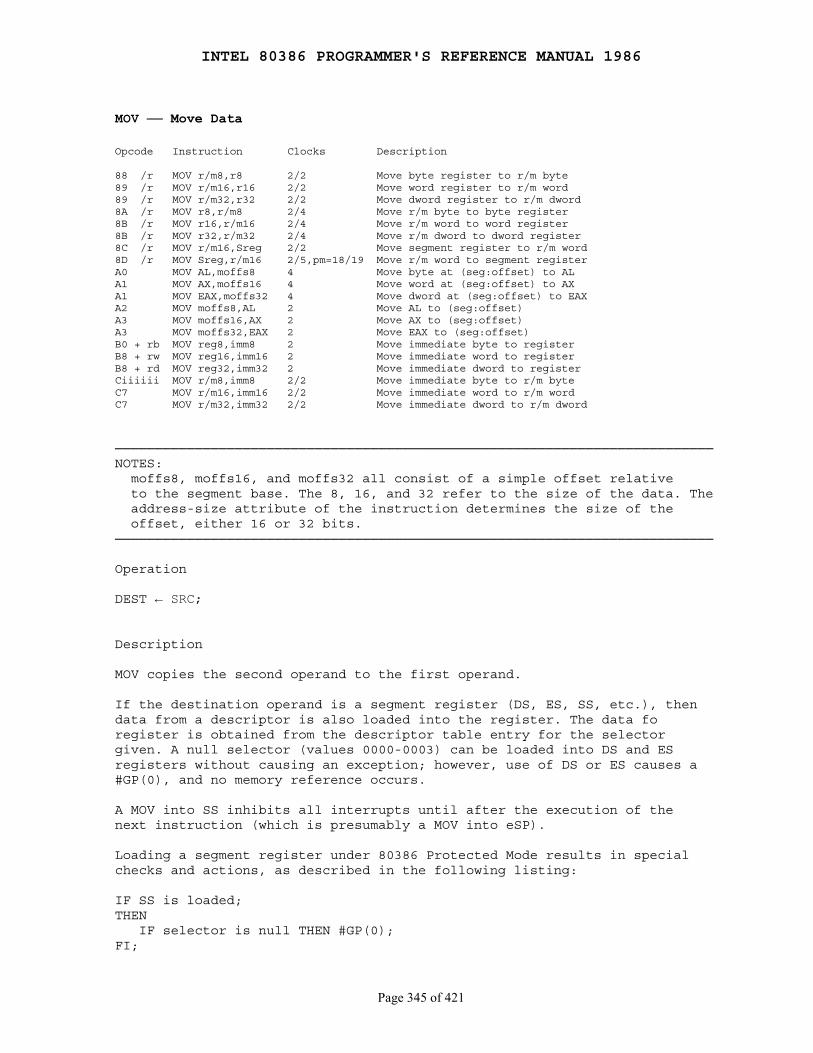
INTEL 80386 PROGRAMMER'S REFERENCE MANUAL 1986
Page 345 of 421
MOV ── Move Data
Opcode Instruction Clocks Description
88 /r MOV r/m8,r8 2/2 Move byte register to r/m byte89 /r MOV r/m16,r16 2/2 Move word register to r/m word89 /r MOV r/m32,r32 2/2 Move dword register to r/m dword8A /r MOV r8,r/m8 2/4 Move r/m byte to byte register8B /r MOV r16,r/m16 2/4 Move r/m word to word register8B /r MOV r32,r/m32 2/4 Move r/m dword to dword register8C /r MOV r/m16,Sreg 2/2 Move segment register to r/m word8D /r MOV Sreg,r/m16 2/5,pm=18/19 Move r/m word to segment registerA0 MOV AL,moffs8 4 Move byte at (seg:offset) to ALA1 MOV AX,moffs16 4 Move word at (seg:offset) to AXA1 MOV EAX,moffs32 4 Move dword at (seg:offset) to EAXA2 MOV moffs8,AL 2 Move AL to (seg:offset)A3 MOV moffs16,AX 2 Move AX to (seg:offset)A3 MOV moffs32,EAX 2 Move EAX to (seg:offset)B0 + rb MOV reg8,imm8 2 Move immediate byte to registerB8 + rw MOV reg16,imm16 2 Move immediate word to registerB8 + rd MOV reg32,imm32 2 Move immediate dword to registerCiiiiii MOV r/m8,imm8 2/2 Move immediate byte to r/m byteC7 MOV r/m16,imm16 2/2 Move immediate word to r/m wordC7 MOV r/m32,imm32 2/2 Move immediate dword to r/m dword
───────────────────────────────────────────────────────────────────────────NOTES: moffs8, moffs16, and moffs32 all consist of a simple offset relative to the segment base. The 8, 16, and 32 refer to the size of the data. The address-size attribute of the instruction determines the size of the offset, either 16 or 32 bits.───────────────────────────────────────────────────────────────────────────
Operation
DEST ← SRC;
Description
MOV copies the second operand to the first operand.
If the destination operand is a segment register (DS, ES, SS, etc.), thendata from a descriptor is also loaded into the register. The data foregister is obtained from the descriptor table entry for the selectorgiven. A null selector (values 0000-0003) can be loaded into DS and ESregisters without causing an exception; however, use of DS or ES causes a#GP(0), and no memory reference occurs.
A MOV into SS inhibits all interrupts until after the execution of thenext instruction (which is presumably a MOV into eSP).
Loading a segment register under 80386 Protected Mode results in specialchecks and actions, as described in the following listing:
IF SS is loaded;THEN IF selector is null THEN #GP(0);FI;
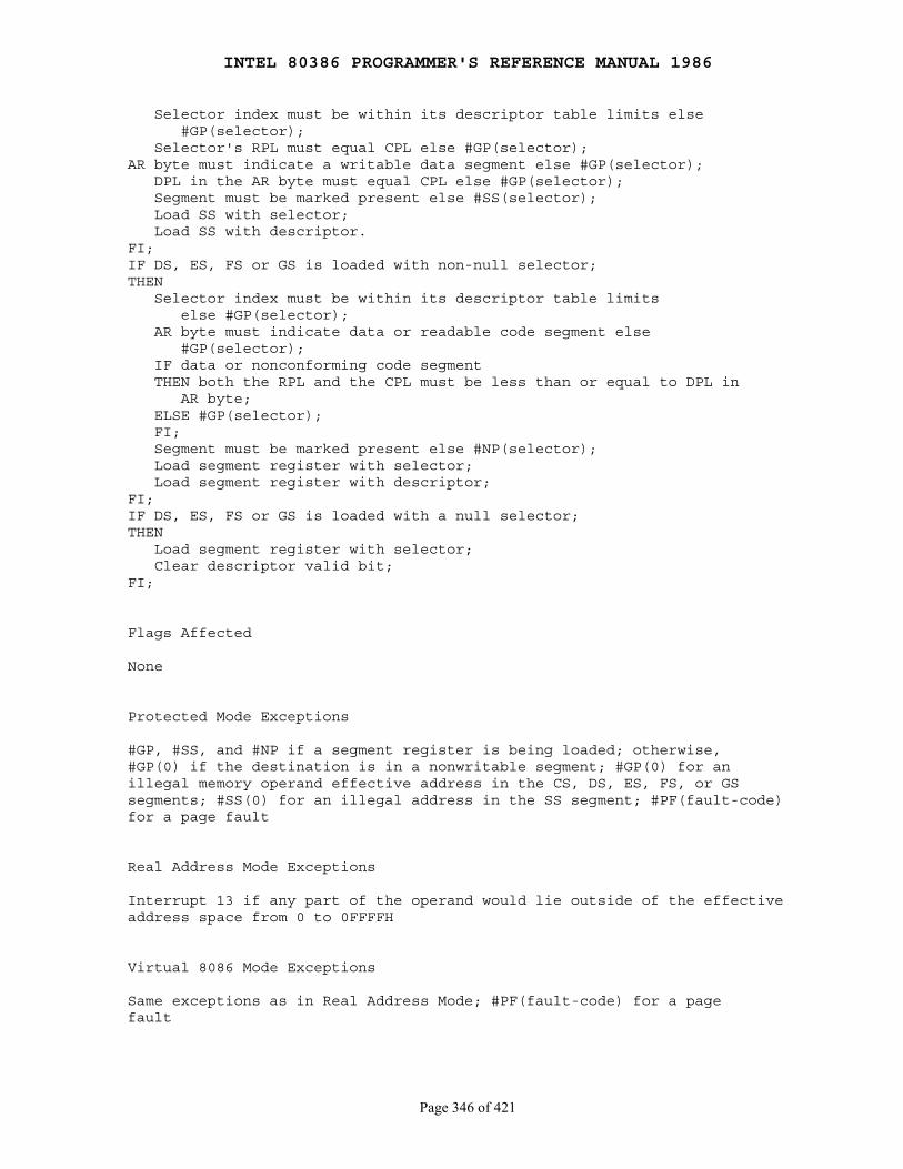
INTEL 80386 PROGRAMMER'S REFERENCE MANUAL 1986
Page 346 of 421
Selector index must be within its descriptor table limits else #GP(selector); Selector's RPL must equal CPL else #GP(selector);AR byte must indicate a writable data segment else #GP(selector); DPL in the AR byte must equal CPL else #GP(selector); Segment must be marked present else #SS(selector); Load SS with selector; Load SS with descriptor.FI;IF DS, ES, FS or GS is loaded with non-null selector;THEN Selector index must be within its descriptor table limits else #GP(selector); AR byte must indicate data or readable code segment else #GP(selector); IF data or nonconforming code segment THEN both the RPL and the CPL must be less than or equal to DPL in AR byte; ELSE #GP(selector); FI; Segment must be marked present else #NP(selector); Load segment register with selector; Load segment register with descriptor;FI;IF DS, ES, FS or GS is loaded with a null selector;THEN Load segment register with selector; Clear descriptor valid bit;FI;
Flags Affected
None
Protected Mode Exceptions
#GP, #SS, and #NP if a segment register is being loaded; otherwise,#GP(0) if the destination is in a nonwritable segment; #GP(0) for anillegal memory operand effective address in the CS, DS, ES, FS, or GSsegments; #SS(0) for an illegal address in the SS segment; #PF(fault-code)for a page fault
Real Address Mode Exceptions
Interrupt 13 if any part of the operand would lie outside of the effectiveaddress space from 0 to 0FFFFH
Virtual 8086 Mode Exceptions
Same exceptions as in Real Address Mode; #PF(fault-code) for a pagefault

INTEL 80386 PROGRAMMER'S REFERENCE MANUAL 1986
Page 347 of 421
MOV ── Move to/from Special Registers
Opcode Instruction Clocks Description
0F 20 /r MOV r32,CR0/CR2/CR3 6 Move (control register) to (register)0F 22 /r MOV CR0/CR2/CR3,r32 10/4/5 Move (register) to (control register)0F 21 /r MOV r32,DR0 -- 3 22 Move (debug register) to (register)0F 21 /r MOV r32,DR6/DR7 14 Move (debug register) to (register)0F 23 /r MOV DR0 -- 3,r32 22 Move (register) to (debug register)0F 23 /r MOV DR6/DR7,r32 16 Move (register) to (debug register)0F 24 /r MOV r32,TR6/TR7 12 Move (test register) to (register)0F 26 /r MOV TR6/TR7,r32 12 Move (register) to (test register)
Operation
DEST ← SRC;
Description
The above forms of MOV store or load the following special registers inor from a general purpose register:
● Control registers CR0, CR2, and CR3 ● Debug Registers DR0, DR1, DR2, DR3, DR6, and DR7 ● Test Registers TR6 and TR7
32-bit operands are always used with these instructions, regardless of theoperand-size attribute.
Flags Affected
OF, SF, ZF, AF, PF, and CF are undefined
Protected Mode Exceptions
#GP(0) if the current privilege level is not 0
Real Address Mode Exceptions
None
Virtual 8086 Mode Exceptions
#GP(0) if instruction execution is attempted
Notes
The instructions must be executed at privilege level 0 or in real-addressmode; otherwise, a protection exception will be raised.
The reg field within the ModRM byte specifies which of the specialregisters in each category is involved. The two bits in the field arealways 11. The r/m field specifies the general register involved.
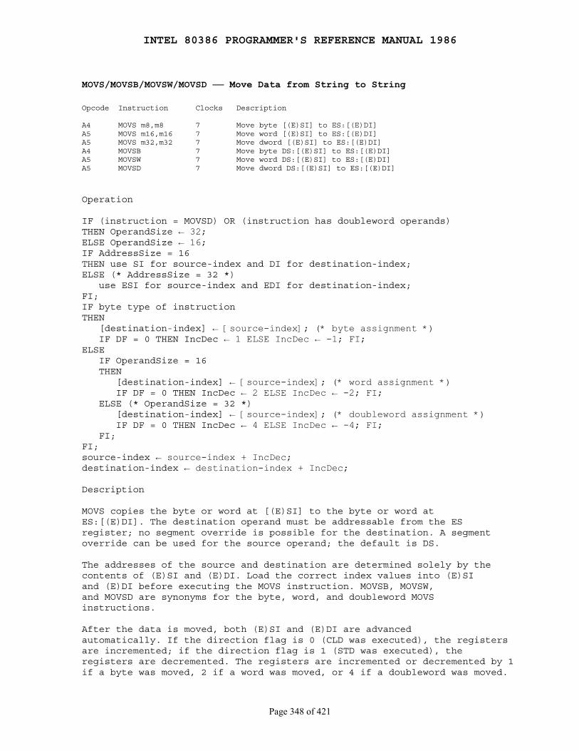
INTEL 80386 PROGRAMMER'S REFERENCE MANUAL 1986
Page 348 of 421
MOVS/MOVSB/MOVSW/MOVSD ── Move Data from String to String
Opcode Instruction Clocks Description
A4 MOVS m8,m8 7 Move byte [(E)SI] to ES:[(E)DI]A5 MOVS m16,m16 7 Move word [(E)SI] to ES:[(E)DI]A5 MOVS m32,m32 7 Move dword [(E)SI] to ES:[(E)DI]A4 MOVSB 7 Move byte DS:[(E)SI] to ES:[(E)DI]A5 MOVSW 7 Move word DS:[(E)SI] to ES:[(E)DI]A5 MOVSD 7 Move dword DS:[(E)SI] to ES:[(E)DI]
Operation
IF (instruction = MOVSD) OR (instruction has doubleword operands)THEN OperandSize ← 32;ELSE OperandSize ← 16;IF AddressSize = 16THEN use SI for source-index and DI for destination-index;ELSE (* AddressSize = 32 *) use ESI for source-index and EDI for destination-index;FI;IF byte type of instructionTHEN [destination-index] ← [source-index]; (* byte assignment *) IF DF = 0 THEN IncDec ← 1 ELSE IncDec ← -1; FI;ELSE IF OperandSize = 16 THEN [destination-index] ← [source-index]; (* word assignment *) IF DF = 0 THEN IncDec ← 2 ELSE IncDec ← -2; FI; ELSE (* OperandSize = 32 *) [destination-index] ← [source-index]; (* doubleword assignment *) IF DF = 0 THEN IncDec ← 4 ELSE IncDec ← -4; FI; FI;FI;source-index ← source-index + IncDec;destination-index ← destination-index + IncDec;
Description
MOVS copies the byte or word at [(E)SI] to the byte or word atES:[(E)DI]. The destination operand must be addressable from the ESregister; no segment override is possible for the destination. A segmentoverride can be used for the source operand; the default is DS.
The addresses of the source and destination are determined solely by thecontents of (E)SI and (E)DI. Load the correct index values into (E)SIand (E)DI before executing the MOVS instruction. MOVSB, MOVSW,and MOVSD are synonyms for the byte, word, and doubleword MOVSinstructions.
After the data is moved, both (E)SI and (E)DI are advancedautomatically. If the direction flag is 0 (CLD was executed), the registersare incremented; if the direction flag is 1 (STD was executed), theregisters are decremented. The registers are incremented or decremented by 1if a byte was moved, 2 if a word was moved, or 4 if a doubleword was moved.
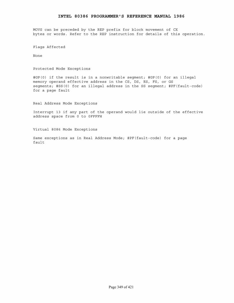
INTEL 80386 PROGRAMMER'S REFERENCE MANUAL 1986
Page 349 of 421
MOVS can be preceded by the REP prefix for block movement of CXbytes or words. Refer to the REP instruction for details of this operation.
Flags Affected
None
Protected Mode Exceptions
#GP(0) if the result is in a nonwritable segment; #GP(0) for an illegalmemory operand effective address in the CS, DS, ES, FS, or GSsegments; #SS(0) for an illegal address in the SS segment; #PF(fault-code)for a page fault
Real Address Mode Exceptions
Interrupt 13 if any part of the operand would lie outside of the effectiveaddress space from 0 to 0FFFFH
Virtual 8086 Mode Exceptions
Same exceptions as in Real Address Mode; #PF(fault-code) for a pagefault

INTEL 80386 PROGRAMMER'S REFERENCE MANUAL 1986
Page 350 of 421
MOVSX ── Move with Sign-Extend
Opcode Instruction Clocks Description
0F BE /r MOVSX r16,r/m8 3/6 Move byte to word with sign-extend0F BE /r MOVSX r32,r/m8 3/6 Move byte to dword, sign-extend0F BF /r MOVSX r32,r/m16 3/6 Move word to dword, sign-extend
Operation
DEST ← SignExtend(SRC);
Description
MOVSX reads the contents of the effective address or register as a byteor a word, sign-extends the value to the operand-size attribute of theinstruction (16 or 32 bits), and stores the result in the destinationregister.
Flags Affected
None
Protected Mode Exceptions
#GP(0) for an illegal memory operand effective address in the CS, DS,ES, FS or GS segments; #SS(0) for an illegal address in the SS segment;#PF(fault-code) for a page fault
Real Address Mode Exceptions
Interrupt 13 if any part of the operand would lie outside of the effectiveaddress space from 0 to 0FFFFH
Virtual 8086 Mode Exceptions
Same exceptions as in Real Address Mode; #PF(fault-code) for a pagefault
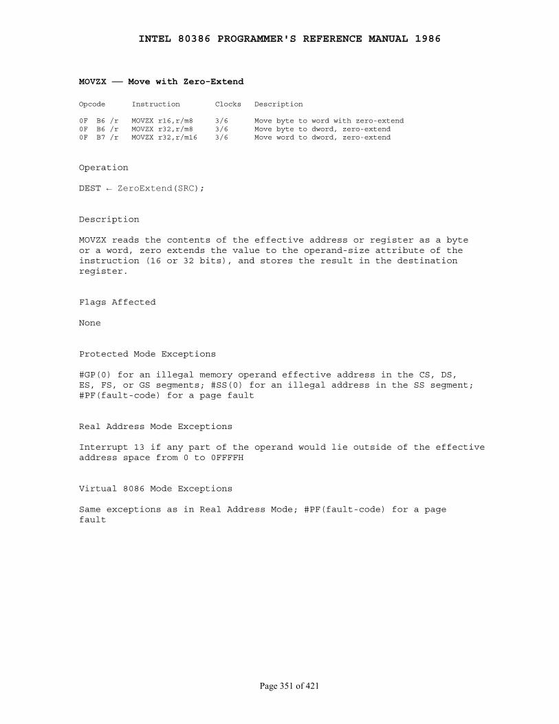
INTEL 80386 PROGRAMMER'S REFERENCE MANUAL 1986
Page 351 of 421
MOVZX ── Move with Zero-Extend
Opcode Instruction Clocks Description
0F B6 /r MOVZX r16,r/m8 3/6 Move byte to word with zero-extend0F B6 /r MOVZX r32,r/m8 3/6 Move byte to dword, zero-extend0F B7 /r MOVZX r32,r/m16 3/6 Move word to dword, zero-extend
Operation
DEST ← ZeroExtend(SRC);
Description
MOVZX reads the contents of the effective address or register as a byteor a word, zero extends the value to the operand-size attribute of theinstruction (16 or 32 bits), and stores the result in the destinationregister.
Flags Affected
None
Protected Mode Exceptions
#GP(0) for an illegal memory operand effective address in the CS, DS,ES, FS, or GS segments; #SS(0) for an illegal address in the SS segment;#PF(fault-code) for a page fault
Real Address Mode Exceptions
Interrupt 13 if any part of the operand would lie outside of the effectiveaddress space from 0 to 0FFFFH
Virtual 8086 Mode Exceptions
Same exceptions as in Real Address Mode; #PF(fault-code) for a pagefault
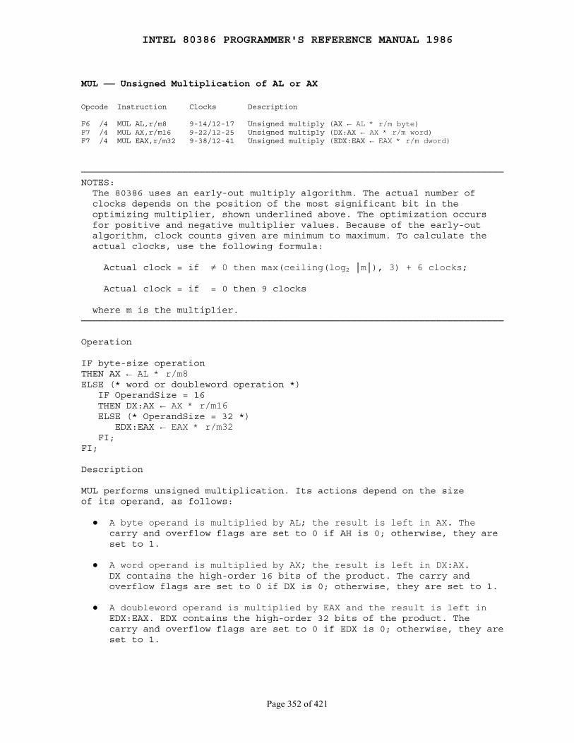
INTEL 80386 PROGRAMMER'S REFERENCE MANUAL 1986
Page 352 of 421
MUL ── Unsigned Multiplication of AL or AX
Opcode Instruction Clocks Description
F6 /4 MUL AL,r/m8 9-14/12-17 Unsigned multiply (AX ← AL * r/m byte)F7 /4 MUL AX,r/m16 9-22/12-25 Unsigned multiply (DX:AX ← AX * r/m word)F7 /4 MUL EAX,r/m32 9-38/12-41 Unsigned multiply (EDX:EAX ← EAX * r/m dword)
───────────────────────────────────────────────────────────────────────────NOTES: The 80386 uses an early-out multiply algorithm. The actual number of clocks depends on the position of the most significant bit in the optimizing multiplier, shown underlined above. The optimization occurs for positive and negative multiplier values. Because of the early-out algorithm, clock counts given are minimum to maximum. To calculate the actual clocks, use the following formula:
Actual clock = if ≠ 0 then max(ceiling(log2 │m│), 3) + 6 clocks;
Actual clock = if = 0 then 9 clocks
where m is the multiplier.───────────────────────────────────────────────────────────────────────────
Operation
IF byte-size operationTHEN AX ← AL * r/m8ELSE (* word or doubleword operation *) IF OperandSize = 16 THEN DX:AX ← AX * r/m16 ELSE (* OperandSize = 32 *) EDX:EAX ← EAX * r/m32 FI;FI;
Description
MUL performs unsigned multiplication. Its actions depend on the sizeof its operand, as follows:
● A byte operand is multiplied by AL; the result is left in AX. The carry and overflow flags are set to 0 if AH is 0; otherwise, they are set to 1.
● A word operand is multiplied by AX; the result is left in DX:AX. DX contains the high-order 16 bits of the product. The carry and overflow flags are set to 0 if DX is 0; otherwise, they are set to 1.
● A doubleword operand is multiplied by EAX and the result is left in EDX:EAX. EDX contains the high-order 32 bits of the product. The carry and overflow flags are set to 0 if EDX is 0; otherwise, they are set to 1.
INTEL 80386 PROGRAMMER'S REFERENCE MANUAL 1986
Page 353 of 421
Flags Affected
OF and CF as described above; SF, ZF, AF, PF, and CF are undefined
Protected Mode Exceptions
#GP(0) for an illegal memory operand effective address in the CS, DS,ES, FS, or GS segments; #SS(0) for an illegal address in the SS segment;#PF(fault-code) for a page fault
Real Address Mode Exceptions
Interrupt 13 if any part of the operand would lie outside of the effectiveaddress space from 0 to 0FFFFH
Virtual 8086 Mode Exceptions
Same exceptions as in Real Address Mode; #PF(fault-code) for a pagefault
INTEL 80386 PROGRAMMER'S REFERENCE MANUAL 1986
Page 354 of 421
NEG ── Two's Complement Negation
Opcode Instruction Clocks Description
F6 /3 NEG r/m8 2/6 Two's complement negate r/m byteF7 /3 NEG r/m16 2/6 Two's complement negate r/m wordF7 /3 NEG r/m32 2/6 Two's complement negate r/m dword
Operation
IF r/m = 0 THEN CF ← 0 ELSE CF ← 1; FI;r/m ← - r/m;
Description
NEG replaces the value of a register or memory operand with its two'scomplement. The operand is subtracted from zero, and the result is placedin the operand.
The carry flag is set to 1, unless the operand is zero, in which case thecarry flag is cleared to 0.
Flags Affected
CF as described above; OF, SF, ZF, and PF as described in Appendix C
Protected Mode Exceptions
#GP(0) if the result is in a nonwritable segment; #GP(0) for an illegalmemory operand effective address in the CS, DS, ES, FS, or GSsegments; #SS(0) for an illegal address in the SS segment; #PF(fault-code)for a page fault
Real Address Mode Exceptions
Interrupt 13 if any part of the operand would lie outside of the effectiveaddress space from 0 to 0FFFFH
Virtual 8086 Mode Exceptions
Same exceptions as in real-address mode; #PF(fault-code) for a pagefault
INTEL 80386 PROGRAMMER'S REFERENCE MANUAL 1986
Page 355 of 421
NOP ── No Operation
Opcode Instruction Clocks Description
90 NOP 3 No operation
Description
NOP performs no operation. NOP is a one-byte instruction that takesup space but affects none of the machine context except (E)IP.
NOP is an alias mnemonic for the XCHG (E)AX, (E)AX instruction.
Flags Affected
None
Protected Mode Exceptions
None
Real Address Mode Exceptions
None
Virtual 8086 Mode Exceptions
None
INTEL 80386 PROGRAMMER'S REFERENCE MANUAL 1986
Page 356 of 421
NOT ── One's Complement Negation
Opcode Instruction Clocks Description
F6 /2 NOT r/m8 2/6 Reverse each bit of r/m byteF7 /2 NOT r/m16 2/6 Reverse each bit of r/m wordF7 /2 NOT r/m32 2/6 Reverse each bit of r/m dword
Operation
r/m ← NOT r/m;
Description
NOT inverts the operand; every 1 becomes a 0, and vice versa.
Flags Affected
None
Protected Mode Exceptions
#GP(0) if the result is in a nonwritable segment; #GP(0) for an illegalmemory operand effective address in the CS, DS, ES, FS, or GSsegments; #SS(0) for an illegal address in the SS segment; #PF(fault-code)for a page fault
Real Address Mode Exceptions
Interrupt 13 if any part of the operand would lie outside of the effectiveaddress space from 0 to 0FFFFH
Virtual 8086 Mode Exceptions
Same exceptions as in real-address mode; #PF(fault-code) for a pagefault
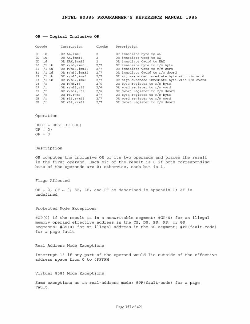
INTEL 80386 PROGRAMMER'S REFERENCE MANUAL 1986
Page 357 of 421
OR ── Logical Inclusive OR
Opcode Instruction Clocks Description
0C ib OR AL,imm8 2 OR immediate byte to AL0D iw OR AX,imm16 2 OR immediate word to AX0D id OR EAX,imm32 2 OR immediate dword to EAX80 /1 ib OR r/m8,imm8 2/7 OR immediate byte to r/m byte81 /1 iw OR r/m16,imm16 2/7 OR immediate word to r/m word81 /1 id OR r/m32,imm32 2/7 OR immediate dword to r/m dword83 /1 ib OR r/m16,imm8 2/7 OR sign-extended immediate byte with r/m word83 /1 ib OR r/m32,imm8 2/7 OR sign-extended immediate byte with r/m dword08 /r OR r/m8,r8 2/6 OR byte register to r/m byte09 /r OR r/m16,r16 2/6 OR word register to r/m word09 /r OR r/m32,r32 2/6 OR dword register to r/m dword0A /r OR r8,r/m8 2/7 OR byte register to r/m byte0B /r OR r16,r/m16 2/7 OR word register to r/m word0B /r OR r32,r/m32 2/7 OR dword register to r/m dword
Operation
DEST ← DEST OR SRC;CF ← 0;OF ← 0
Description
OR computes the inclusive OR of its two operands and places the resultin the first operand. Each bit of the result is 0 if both correspondingbits of the operands are 0; otherwise, each bit is 1.
Flags Affected
OF ← 0, CF ← 0; SF, ZF, and PF as described in Appendix C; AF isundefined
Protected Mode Exceptions
#GP(0) if the result is in a nonwritable segment; #GP(0) for an illegalmemory operand effective address in the CS, DS, ES, FS, or GSsegments; #SS(0) for an illegal address in the SS segment; #PF(fault-code)for a page fault
Real Address Mode Exceptions
Interrupt 13 if any part of the operand would lie outside of the effectiveaddress space from 0 to 0FFFFH
Virtual 8086 Mode Exceptions
Same exceptions as in real-address mode; #PF(fault-code) for a pageFault.

INTEL 80386 PROGRAMMER'S REFERENCE MANUAL 1986
Page 358 of 421
OUT ── Output to Port
Opcode Instruction Clocks Description
E6 ib OUT imm8,AL 10,pm=4*/24** Output byte AL to immediate port numberE7 ib OUT imm8,AX 10,pm=4*/24** Output word AL to immediate port numberE7 ib OUT imm8,EAX 10,pm=4*/24** Output dword AL to immediate port numberEE OUT DX,AL 11,pm=5*/25** Output byte AL to port number in DXEF OUT DX,AX 11,pm=5*/25** Output word AL to port number in DXEF OUT DX,EAX 11,pm=5*/25** Output dword AL to port number in DX
───────────────────────────────────────────────────────────────────────────NOTES: *If CPL ≤ IOPL **If CPL > IOPL or if in virtual 8086 mode───────────────────────────────────────────────────────────────────────────
Operation
IF (PE = 1) AND ((VM = 1) OR (CPL > IOPL))THEN (* Virtual 8086 mode, or protected mode with CPL > IOPL *) IF NOT I-O-Permission (DEST, width(DEST)) THEN #GP(0); FI;FI;[DEST] ← SRC; (* I/O address space used *)
Description
OUT transfers a data byte or data word from the register (AL, AX, orEAX) given as the second operand to the output port numbered by thefirst operand. Output to any port from 0 to 65535 is performed by placingthe port number in the DX register and then using an OUT instructionwith DX as the first operand. If the instruction contains an eight-bit portID, that value is zero-extended to 16 bits.
Flags Affected
None
Protected Mode Exceptions
#GP(0) if the current privilege level is higher (has less privilege) thanIOPL and any of the corresponding I/O permission bits in TSS equals 1
Real Address Mode Exceptions
None
Virtual 8086 Mode Exceptions
#GP(0) fault if any of the corresponding I/O permission bits in TSSequals 1
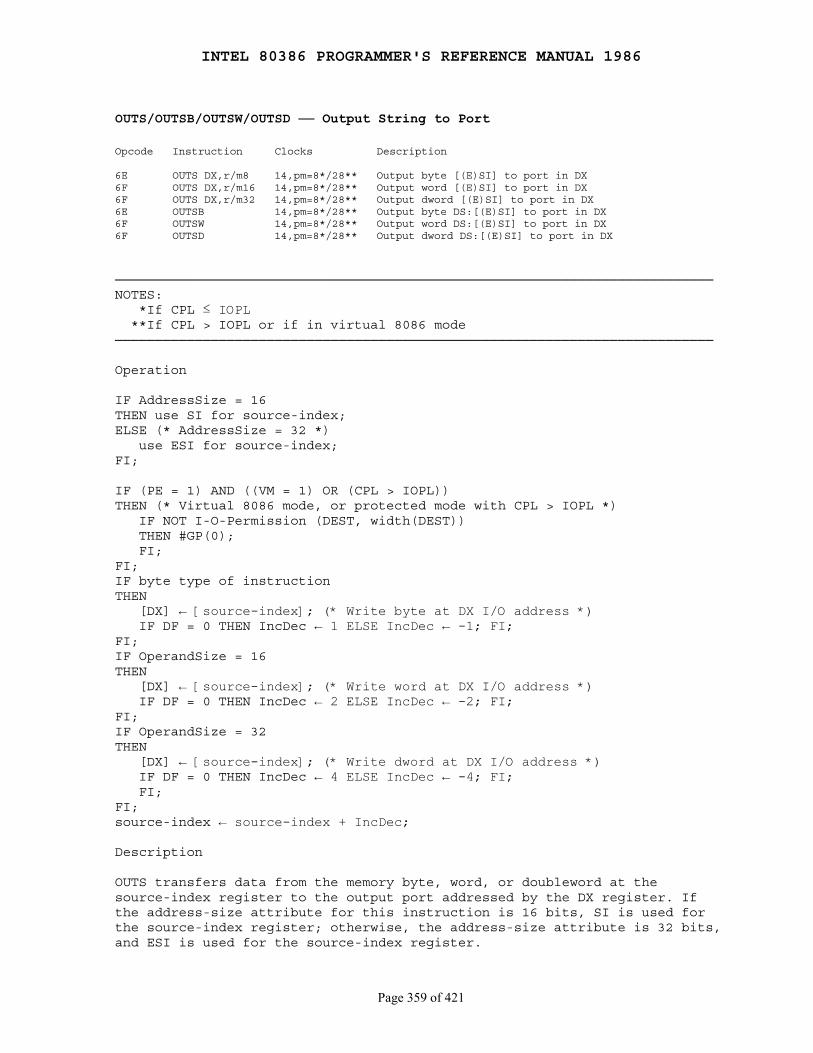
INTEL 80386 PROGRAMMER'S REFERENCE MANUAL 1986
Page 359 of 421
OUTS/OUTSB/OUTSW/OUTSD ── Output String to Port
Opcode Instruction Clocks Description
6E OUTS DX,r/m8 14,pm=8*/28** Output byte [(E)SI] to port in DX6F OUTS DX,r/m16 14,pm=8*/28** Output word [(E)SI] to port in DX6F OUTS DX,r/m32 14,pm=8*/28** Output dword [(E)SI] to port in DX6E OUTSB 14,pm=8*/28** Output byte DS:[(E)SI] to port in DX6F OUTSW 14,pm=8*/28** Output word DS:[(E)SI] to port in DX6F OUTSD 14,pm=8*/28** Output dword DS:[(E)SI] to port in DX
───────────────────────────────────────────────────────────────────────────NOTES: *If CPL ≤ IOPL **If CPL > IOPL or if in virtual 8086 mode───────────────────────────────────────────────────────────────────────────
Operation
IF AddressSize = 16THEN use SI for source-index;ELSE (* AddressSize = 32 *) use ESI for source-index;FI;
IF (PE = 1) AND ((VM = 1) OR (CPL > IOPL))THEN (* Virtual 8086 mode, or protected mode with CPL > IOPL *) IF NOT I-O-Permission (DEST, width(DEST)) THEN #GP(0); FI;FI;IF byte type of instructionTHEN [DX] ← [source-index]; (* Write byte at DX I/O address *) IF DF = 0 THEN IncDec ← 1 ELSE IncDec ← -1; FI;FI;IF OperandSize = 16THEN [DX] ← [source-index]; (* Write word at DX I/O address *) IF DF = 0 THEN IncDec ← 2 ELSE IncDec ← -2; FI;FI;IF OperandSize = 32THEN [DX] ← [source-index]; (* Write dword at DX I/O address *) IF DF = 0 THEN IncDec ← 4 ELSE IncDec ← -4; FI; FI;FI;source-index ← source-index + IncDec;
Description
OUTS transfers data from the memory byte, word, or doubleword at thesource-index register to the output port addressed by the DX register. Ifthe address-size attribute for this instruction is 16 bits, SI is used forthe source-index register; otherwise, the address-size attribute is 32 bits,and ESI is used for the source-index register.
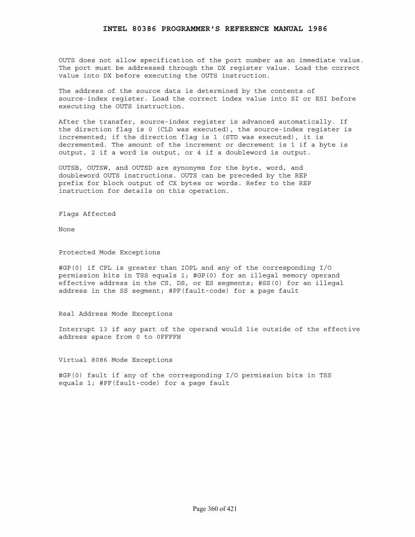
INTEL 80386 PROGRAMMER'S REFERENCE MANUAL 1986
Page 360 of 421
OUTS does not allow specification of the port number as an immediate value.The port must be addressed through the DX register value. Load the correctvalue into DX before executing the OUTS instruction.
The address of the source data is determined by the contents ofsource-index register. Load the correct index value into SI or ESI beforeexecuting the OUTS instruction.
After the transfer, source-index register is advanced automatically. Ifthe direction flag is 0 (CLD was executed), the source-index register isincremented; if the direction flag is 1 (STD was executed), it isdecremented. The amount of the increment or decrement is 1 if a byte isoutput, 2 if a word is output, or 4 if a doubleword is output.
OUTSB, OUTSW, and OUTSD are synonyms for the byte, word, anddoubleword OUTS instructions. OUTS can be preceded by the REPprefix for block output of CX bytes or words. Refer to the REPinstruction for details on this operation.
Flags Affected
None
Protected Mode Exceptions
#GP(0) if CPL is greater than IOPL and any of the corresponding I/Opermission bits in TSS equals 1; #GP(0) for an illegal memory operandeffective address in the CS, DS, or ES segments; #SS(0) for an illegaladdress in the SS segment; #PF(fault-code) for a page fault
Real Address Mode Exceptions
Interrupt 13 if any part of the operand would lie outside of the effectiveaddress space from 0 to 0FFFFH
Virtual 8086 Mode Exceptions
#GP(0) fault if any of the corresponding I/O permission bits in TSSequals 1; #PF(fault-code) for a page fault
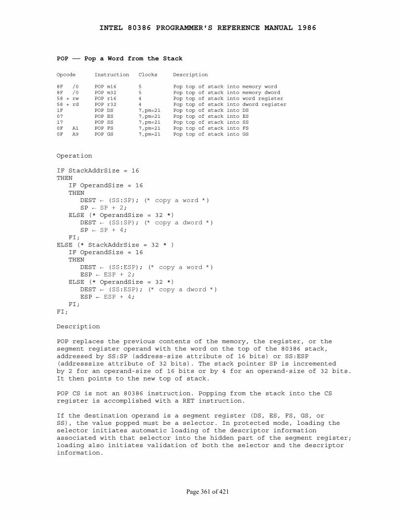
INTEL 80386 PROGRAMMER'S REFERENCE MANUAL 1986
Page 361 of 421
POP ── Pop a Word from the Stack
Opcode Instruction Clocks Description
8F /0 POP m16 5 Pop top of stack into memory word8F /0 POP m32 5 Pop top of stack into memory dword58 + rw POP r16 4 Pop top of stack into word register58 + rd POP r32 4 Pop top of stack into dword register1F POP DS 7,pm=21 Pop top of stack into DS07 POP ES 7,pm=21 Pop top of stack into ES17 POP SS 7,pm=21 Pop top of stack into SS0F A1 POP FS 7,pm=21 Pop top of stack into FS0F A9 POP GS 7,pm=21 Pop top of stack into GS
Operation
IF StackAddrSize = 16THEN IF OperandSize = 16 THEN DEST ← (SS:SP); (* copy a word *) SP ← SP + 2; ELSE (* OperandSize = 32 *) DEST ← (SS:SP); (* copy a dword *) SP ← SP + 4; FI;ELSE (* StackAddrSize = 32 * ) IF OperandSize = 16 THEN DEST ← (SS:ESP); (* copy a word *) ESP ← ESP + 2; ELSE (* OperandSize = 32 *) DEST ← (SS:ESP); (* copy a dword *) ESP ← ESP + 4; FI;FI;
Description
POP replaces the previous contents of the memory, the register, or thesegment register operand with the word on the top of the 80386 stack,addressed by SS:SP (address-size attribute of 16 bits) or SS:ESP(addresssize attribute of 32 bits). The stack pointer SP is incrementedby 2 for an operand-size of 16 bits or by 4 for an operand-size of 32 bits.It then points to the new top of stack.
POP CS is not an 80386 instruction. Popping from the stack into the CSregister is accomplished with a RET instruction.
If the destination operand is a segment register (DS, ES, FS, GS, orSS), the value popped must be a selector. In protected mode, loading theselector initiates automatic loading of the descriptor informationassociated with that selector into the hidden part of the segment register;loading also initiates validation of both the selector and the descriptorinformation.
INTEL 80386 PROGRAMMER'S REFERENCE MANUAL 1986
Page 362 of 421
A null value (0000-0003) may be popped into the DS, ES, FS, or GSregister without causing a protection exception. An attempt to referencea segment whose corresponding segment register is loaded with a nullvalue causes a #GP(0) exception. No memory reference occurs. The savedvalue of the segment register is null.
A POP SS instruction inhibits all interrupts, including NMI, until afterexecution of the next instruction. This allows sequential execution of POPSS and POP eSP instructions without danger of having an invalid stackduring an interrupt. However, use of the LSS instruction is the preferredmethod of loading the SS and eSP registers.
Loading a segment register while in protected mode results in specialchecks and actions, as described in the following listing:
IF SS is loaded: IF selector is null THEN #GP(0); Selector index must be within its descriptor table limits ELSE #GP(selector); Selector's RPL must equal CPL ELSE #GP(selector); AR byte must indicate a writable data segment ELSE #GP(selector); DPL in the AR byte must equal CPL ELSE #GP(selector); Segment must be marked present ELSE #SS(selector); Load SS register with selector; Load SS register with descriptor;
IF DS, ES, FS or GS is loaded with non-null selector: AR byte must indicate data or readable code segment ELSE #GP(selector); IF data or nonconforming code THEN both the RPL and the CPL must be less than or equal to DPL in AR byte ELSE #GP(selector); FI; Segment must be marked present ELSE #NP(selector); Load segment register with selector; Load segment register with descriptor;
IF DS, ES, FS, or GS is loaded with a null selector: Load segment register with selector Clear valid bit in invisible portion of register
Flags Affected
None
Protected Mode Exceptions
#GP, #SS, and #NP if a segment register is being loaded; #SS(0) if thecurrent top of stack is not within the stack segment; #GP(0) if the resultis in a nonwritable segment; #GP(0) for an illegal memory operandeffective address in the CS, DS, ES, FS, or GS segments; #SS(0) for anillegal address in the SS segment; #PF(fault-code) for a page fault
INTEL 80386 PROGRAMMER'S REFERENCE MANUAL 1986
Page 363 of 421
Real Address Mode Exceptions
Interrupt 13 if any part of the operand would lie outside of the effectiveaddress space from 0 to 0FFFFH
Virtual 8086 Mode Exceptions
Same exceptions as in real-address mode; #PF(fault-code) for a pagefault
INTEL 80386 PROGRAMMER'S REFERENCE MANUAL 1986
Page 364 of 421
POPA/POPAD ── Pop all General Registers
Opcode Instruction Clocks Description
61 POPA 24 Pop DI, SI, BP, SP, BX, DX, CX, and AX61 POPAD 24 Pop EDI, ESI, EBP, ESP, EDX, ECX, and EAX
Operation
IF OperandSize = 16 (* instruction = POPA *)THEN DI ← Pop(); SI ← Pop(); BP ← Pop(); throwaway ← Pop (); (* Skip SP *) BX ← Pop(); DX ← Pop(); CX ← Pop(); AX ← Pop();ELSE (* OperandSize = 32, instruction = POPAD *) EDI ← Pop(); ESI ← Pop(); EBP ← Pop(); throwaway ← Pop (); (* Skip ESP *) EBX ← Pop(); EDX ← Pop(); ECX ← Pop(); EAX ← Pop();FI;
Description
POPA pops the eight 16-bit general registers. However, the SP value isdiscarded instead of loaded into SP. POPA reverses a previous PUSHA,restoring the general registers to their values before PUSHA wasexecuted. The first register popped is DI.
POPAD pops the eight 32-bit general registers. The ESP value isdiscarded instead of loaded into ESP. POPAD reverses the previousPUSHAD, restoring the general registers to their values before PUSHADwas executed. The first register popped is EDI.
Flags Affected
None
Protected Mode Exceptions
#SS(0) if the starting or ending stack address is not within the stacksegment; #PF(fault-code) for a page fault

INTEL 80386 PROGRAMMER'S REFERENCE MANUAL 1986
Page 365 of 421
Real Address Mode Exceptions
Interrupt 13 if any part of the operand would lie outside of the effectiveaddress space from 0 to 0FFFFH
Virtual 8086 Mode Exceptions
Same exceptions as in real-address mode; #PF(fault-code) for a pagefault
INTEL 80386 PROGRAMMER'S REFERENCE MANUAL 1986
Page 366 of 421
POPF/POPFD ── Pop Stack into FLAGS or EFLAGS Register
Opcode Instruction Clocks Description
9D POPF 5 Pop top of stack FLAGS9D POPFD 5 Pop top of stack into EFLAGS
Operation
Flags ← Pop();
Description
POPF/POPFD pops the word or doubleword on the top of the stack andstores the value in the flags register. If the operand-size attribute ofthe instruction is 16 bits, then a word is popped and the value is stored inFLAGS. If the operand-size attribute is 32 bits, then a doubleword is poppedand the value is stored in EFLAGS.
Refer to Chapter 2 and Chapter 4 for information about the FLAGSand EFLAGS registers. Note that bits 16 and 17 of EFLAGS, calledVM and RF, respectively, are not affected by POPF or POPFD.
The I/O privilege level is altered only when executing at privilege level0. The interrupt flag is altered only when executing at a level at least asprivileged as the I/O privilege level. (Real-address mode is equivalent toprivilege level 0.) If a POPF instruction is executed with insufficientprivilege, an exception does not occur, but the privileged bits do notchange.
Flags Affected
All flags except VM and RF
Protected Mode Exceptions
#SS(0) if the top of stack is not within the stack segment
Real Address Mode Exceptions
Interrupt 13 if any part of the operand would lie outside of the effectiveaddress space from 0 to 0FFFFH
Virtual 8086 Mode Exceptions
#GP(0) fault if IOPL is less than 3, to permit emulation
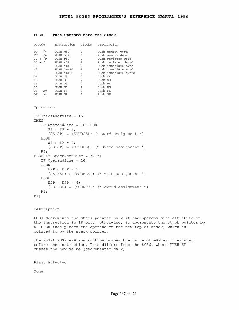
INTEL 80386 PROGRAMMER'S REFERENCE MANUAL 1986
Page 367 of 421
PUSH ── Push Operand onto the Stack
Opcode Instruction Clocks Description
FF /6 PUSH m16 5 Push memory wordFF /6 PUSH m32 5 Push memory dword50 + /r PUSH r16 2 Push register word50 + /r PUSH r32 2 Push register dword6A PUSH imm8 2 Push immediate byte68 PUSH imm16 2 Push immediate word68 PUSH imm32 2 Push immediate dword0E PUSH CS 2 Push CS16 PUSH SS 2 Push SS1E PUSH DS 2 Push DS06 PUSH ES 2 Push ES0F A0 PUSH FS 2 Push FSOF A8 PUSH GS 2 Push GS
Operation
IF StackAddrSize = 16THEN IF OperandSize = 16 THEN SP ← SP - 2; (SS:SP) ← (SOURCE); (* word assignment *) ELSE SP ← SP - 4; (SS:SP) ← (SOURCE); (* dword assignment *) FI;ELSE (* StackAddrSize = 32 *) IF OperandSize = 16 THEN ESP ← ESP - 2; (SS:ESP) ← (SOURCE); (* word assignment *) ELSE ESP ← ESP - 4; (SS:ESP) ← (SOURCE); (* dword assignment *) FI;FI;
Description
PUSH decrements the stack pointer by 2 if the operand-size attribute ofthe instruction is 16 bits; otherwise, it decrements the stack pointer by4. PUSH then places the operand on the new top of stack, which ispointed to by the stack pointer.
The 80386 PUSH eSP instruction pushes the value of eSP as it existedbefore the instruction. This differs from the 8086, where PUSH SPpushes the new value (decremented by 2).
Flags Affected
None

INTEL 80386 PROGRAMMER'S REFERENCE MANUAL 1986
Page 368 of 421
Protected Mode Exceptions
#SS(0) if the new value of SP or ESP is outside the stack segment limit;#GP(0) for an illegal memory operand effective address in the CS, DS,ES, FS, or GS segments; #SS(0) for an illegal address in the SS segment;#PF(fault-code) for a page fault
Real Address Mode Exceptions
None; if SP or ESP is 1, the 80386 shuts down due to a lack of stackspace
Virtual 8086 Mode Exceptions
Same exceptions as in real-address mode; #PF(fault-code) for a pagefault
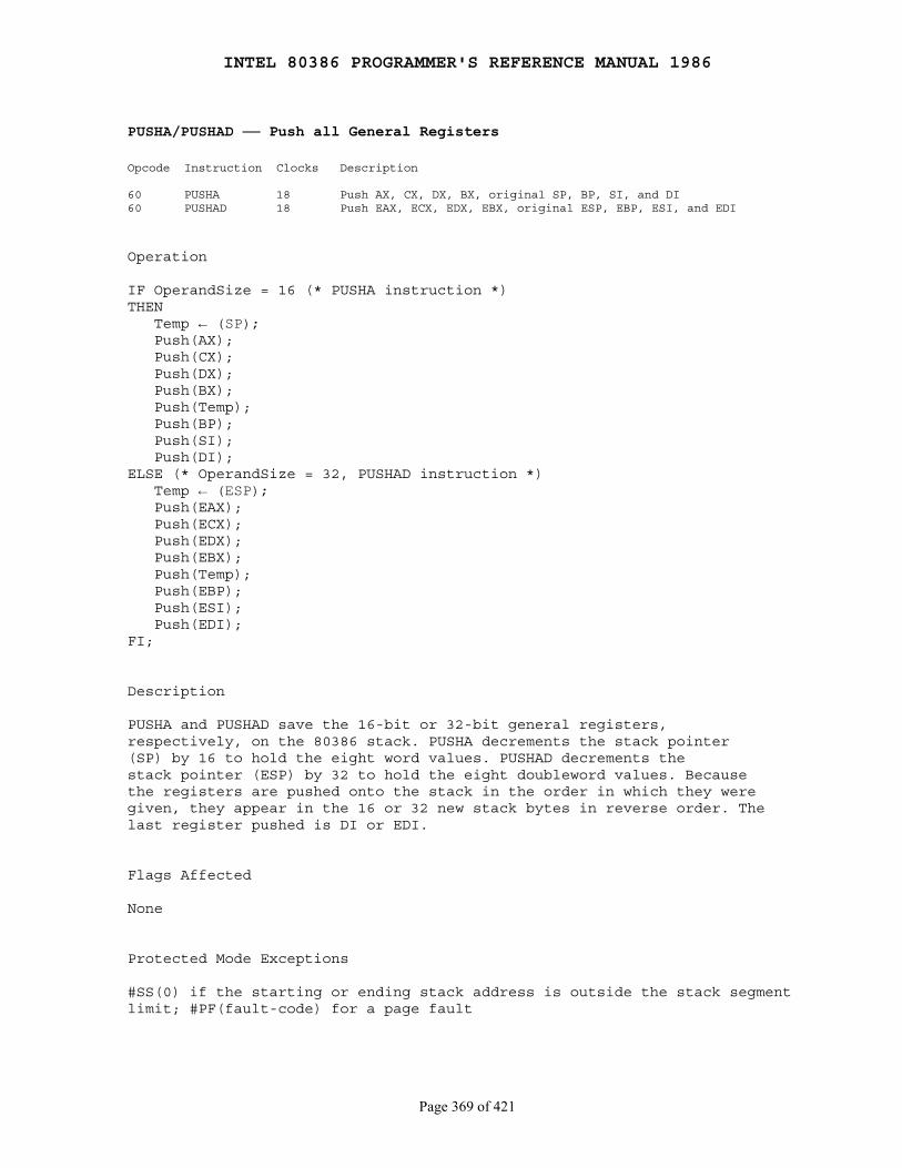
INTEL 80386 PROGRAMMER'S REFERENCE MANUAL 1986
Page 369 of 421
PUSHA/PUSHAD ── Push all General Registers
Opcode Instruction Clocks Description
60 PUSHA 18 Push AX, CX, DX, BX, original SP, BP, SI, and DI60 PUSHAD 18 Push EAX, ECX, EDX, EBX, original ESP, EBP, ESI, and EDI
Operation
IF OperandSize = 16 (* PUSHA instruction *)THEN Temp ← (SP); Push(AX); Push(CX); Push(DX); Push(BX); Push(Temp); Push(BP); Push(SI); Push(DI);ELSE (* OperandSize = 32, PUSHAD instruction *) Temp ← (ESP); Push(EAX); Push(ECX); Push(EDX); Push(EBX); Push(Temp); Push(EBP); Push(ESI); Push(EDI);FI;
Description
PUSHA and PUSHAD save the 16-bit or 32-bit general registers,respectively, on the 80386 stack. PUSHA decrements the stack pointer(SP) by 16 to hold the eight word values. PUSHAD decrements thestack pointer (ESP) by 32 to hold the eight doubleword values. Becausethe registers are pushed onto the stack in the order in which they weregiven, they appear in the 16 or 32 new stack bytes in reverse order. Thelast register pushed is DI or EDI.
Flags Affected
None
Protected Mode Exceptions
#SS(0) if the starting or ending stack address is outside the stack segmentlimit; #PF(fault-code) for a page fault
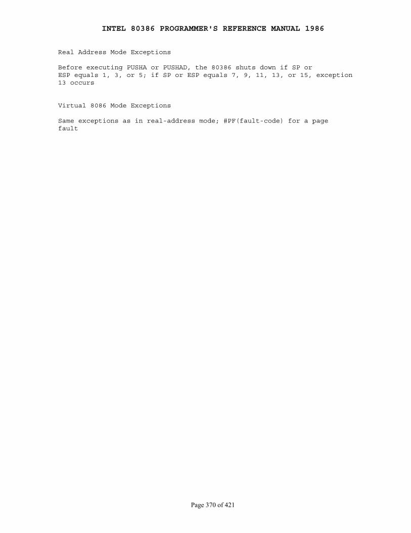
INTEL 80386 PROGRAMMER'S REFERENCE MANUAL 1986
Page 370 of 421
Real Address Mode Exceptions
Before executing PUSHA or PUSHAD, the 80386 shuts down if SP orESP equals 1, 3, or 5; if SP or ESP equals 7, 9, 11, 13, or 15, exception13 occurs
Virtual 8086 Mode Exceptions
Same exceptions as in real-address mode; #PF(fault-code) for a pagefault

INTEL 80386 PROGRAMMER'S REFERENCE MANUAL 1986
Page 371 of 421
PUSHF/PUSHFD ── Push Flags Register onto the Stack
Opcode Instruction Clocks Description
9C PUSHF 4 Push FLAGS9C PUSHFD 4 Push EFLAGS
Operation
IF OperandSize = 32THEN push(EFLAGS);ELSE push(FLAGS);FI;
Description
PUSHF decrements the stack pointer by 2 and copies the FLAGSregister to the new top of stack; PUSHFD decrements the stack pointer by4, and the 80386 EFLAGS register is copied to the new top of stackwhich is pointed to by SS:eSP. Refer to Chapter 2 and Chapter 4 forinformation on the EFLAGS register.
Flags Affected
None
Protected Mode Exceptions
#SS(0) if the new value of eSP is outside the stack segment boundaries
Real Address Mode Exceptions
None; the 80386 shuts down due to a lack of stack space
Virtual 8086 Mode Exceptions
#GP(0) fault if IOPL is less than 3, to permit emulation
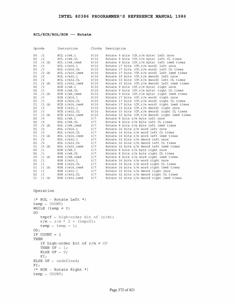
INTEL 80386 PROGRAMMER'S REFERENCE MANUAL 1986
Page 372 of 421
RCL/RCR/ROL/ROR ── Rotate
Opcode Instruction Clocks Description
D0 /2 RCL r/m8,1 9/10 Rotate 9 bits (CF,r/m byte) left onceD2 /2 RCL r/m8,CL 9/10 Rotate 9 bits (CF,r/m byte) left CL timesC0 /2 ib RCL r/m8,imm8 9/10 Rotate 9 bits (CF,r/m byte) left imm8 timesD1 /2 RCL r/m16,1 9/10 Rotate 17 bits (CF,r/m word) left onceD3 /2 RCL r/m16,CL 9/10 Rotate 17 bits (CF,r/m word) left CL timesC1 /2 ib RCL r/m16,imm8 9/10 Rotate 17 bits (CF,r/m word) left imm8 timesD1 /2 RCL r/m32,1 9/10 Rotate 33 bits (CF,r/m dword) left onceD3 /2 RCL r/m32,CL 9/10 Rotate 33 bits (CF,r/m dword) left CL timesC1 /2 ib RCL r/m32,imm8 9/10 Rotate 33 bits (CF,r/m dword) left imm8 timesD0 /3 RCR r/m8,1 9/10 Rotate 9 bits (CF,r/m byte) right onceD2 /3 RCR r/m8,CL 9/10 Rotate 9 bits (CF,r/m byte) right CL timesC0 /3 ib RCR r/m8,imm8 9/10 Rotate 9 bits (CF,r/m byte) right imm8 timesD1 /3 RCR r/m16,1 9/10 Rotate 17 bits (CF,r/m word) right onceD3 /3 RCR r/m16,CL 9/10 Rotate 17 bits (CF,r/m word) right CL timesC1 /3 ib RCR r/m16,imm8 9/10 Rotate 17 bits (CF,r/m word) right imm8 timesD1 /3 RCR r/m32,1 9/10 Rotate 33 bits (CF,r/m dword) right onceD3 /3 RCR r/m32,CL 9/10 Rotate 33 bits (CF,r/m dword) right CL timesC1 /3 ib RCR r/m32,imm8 9/10 Rotate 33 bits (CF,r/m dword) right imm8 timesD0 /0 ROL r/m8,1 3/7 Rotate 8 bits r/m byte left onceD2 /0 ROL r/m8,CL 3/7 Rotate 8 bits r/m byte left CL timesC0 /0 ib ROL r/m8,imm8 3/7 Rotate 8 bits r/m byte left imm8 timesD1 /0 ROL r/m16,1 3/7 Rotate 16 bits r/m word left onceD3 /0 ROL r/m16,CL 3/7 Rotate 16 bits r/m word left CL timesC1 /0 ib ROL r/m16,imm8 3/7 Rotate 16 bits r/m word left imm8 timesD1 /0 ROL r/m32,1 3/7 Rotate 32 bits r/m dword left onceD3 /0 ROL r/m32,CL 3/7 Rotate 32 bits r/m dword left CL timesC1 /0 ib ROL r/m32,imm8 3/7 Rotate 32 bits r/m dword left imm8 timesD0 /1 ROR r/m8,1 3/7 Rotate 8 bits r/m byte right onceD2 /1 ROR r/m8,CL 3/7 Rotate 8 bits r/m byte right CL timesC0 /1 ib ROR r/m8,imm8 3/7 Rotate 8 bits r/m word right imm8 timesD1 /1 ROR r/m16,1 3/7 Rotate 16 bits r/m word right onceD3 /1 ROR r/m16,CL 3/7 Rotate 16 bits r/m word right CL timesC1 /1 ib ROR r/m16,imm8 3/7 Rotate 16 bits r/m word right imm8 timesD1 /1 ROR r/m32,1 3/7 Rotate 32 bits r/m dword right onceD3 /1 ROR r/m32,CL 3/7 Rotate 32 bits r/m dword right CL timesC1 /1 ib ROR r/m32,imm8 3/7 Rotate 32 bits r/m dword right imm8 times
Operation
(* ROL - Rotate Left *)temp ← COUNT;WHILE (temp ≠ 0)DO tmpcf ← high-order bit of (r/m); r/m ← r/m * 2 + (tmpcf); temp ← temp - 1;OD;IF COUNT = 1THEN IF high-order bit of r/m ≠ CF THEN OF ← 1; ELSE OF ← 0; FI;ELSE OF ← undefined;FI;(* ROR - Rotate Right *)temp ← COUNT;
INTEL 80386 PROGRAMMER'S REFERENCE MANUAL 1986
Page 373 of 421
WHILE (temp ≠ 0 )DO tmpcf ← low-order bit of (r/m); r/m ← r/m / 2 + (tmpcf * 2^(width(r/m))); temp ← temp - 1;DO;IF COUNT = 1THEN IF (high-order bit of r/m) ≠ (bit next to high-order bit of r/m) THEN OF ← 1; ELSE OF ← 0; FI;ELSE OF ← undefined;FI;
Description
Each rotate instruction shifts the bits of the register or memory operandgiven. The left rotate instructions shift all the bits upward, except forthe top bit, which is returned to the bottom. The right rotate instructionsdo the reverse: the bits shift downward until the bottom bit arrives atthe top.
For the RCL and RCR instructions, the carry flag is part of the rotatedquantity. RCL shifts the carry flag into the bottom bit and shifts the topbit into the carry flag; RCR shifts the carry flag into the top bit andshifts the bottom bit into the carry flag. For the ROL and RORinstructions, the original value of the carry flag is not a part of theresult, but the carry flag receives a copy of the bit that was shifted fromone end to the other.
The rotate is repeated the number of times indicated by the secondoperand, which is either an immediate number or the contents of the CLregister. To reduce the maximum instruction execution time, the 80386does not allow rotation counts greater than 31. If a rotation count greaterthan 31 is attempted, only the bottom five bits of the rotation are used.The 8086 does not mask rotation counts. The 80386 in Virtual 8086 Mode doesmask rotation counts.
The overflow flag is defined only for the single-rotate forms of theinstructions (second operand = 1). It is undefined in all other cases. Forleft shifts/rotates, the CF bit after the shift is XORed with thehigh-order result bit. For right shifts/rotates, the high-order two bits ofthe result are XORed to get OF.
Flags Affected
OF only for single rotates; OF is undefined for multi-bit rotates; CF asdescribed above
Protected Mode Exceptions
#GP(0) if the result is in a nonwritable segment; #GP(0) for an illegalmemory operand effective address in the CS, DS, ES, FS, or GSsegments; #SS(0) for an illegal address in the SS segment; #PF(fault-code)for a page fault

INTEL 80386 PROGRAMMER'S REFERENCE MANUAL 1986
Page 374 of 421
Real Address Mode Exceptions
Interrupt 13 if any part of the operand would lie outside of the effectiveaddress space from 0 to 0FFFFH
Virtual 8086 Mode Exceptions
Same exceptions as in Real Address Mode; #PF(fault-code) for a pagefault

INTEL 80386 PROGRAMMER'S REFERENCE MANUAL 1986
Page 375 of 421
REP/REPE/REPZ/REPNE/REPNZ ── Repeat Following String Operation
Opcode Instruction Clocks Description
F3 6C REP INS r/m8, DX 13+6*(E)CX, pm=7+6*(E)CXIf CPL ≤ IOPL/ 27+6*(E)CXIf CPL > IOPL or if in virtual 8086 mode Input (E)CX bytes from port DX into ES:[(E)DI]F3 6D REP INS r/m16,DX 13+6*(E)CX, pm=7+6*(E)CXIf CPL ≤ IOPL/ 27+6*(E)CXIf CPL > IOPL or if in virtual 8086 mode Input (E)CX words from port DX into ES:[(E)DI]F3 6D REP INS r/m32,DX 13+6*(E)CX, pm=7+6*(E)CXIf CPL ≤ IOPL/ 27+6*(E)CXIf CPL > IOPL or if in virtual 8086 mode Input (E)CX dwords from port DX into ES:[(E)DI]F3 A4 REP MOVS m8,m8 5+4*(E)CX Move (E)CX bytes from [(E)SI] to ES:[(E)DI]F3 A5 REP MOVS m16,m16 5+4*(E)CX Move (E)CX words from [(E)SI] to ES:[(E)DI]F3 A5 REP MOVS m32,m32 5+4*(E)CX Move (E)CX dwords from [(E)SI] to ES:[(E)DI]F3 6E REP OUTS DX,r/m8 5+12*(E)CX, pm=6+5*(E)CXIf CPL ≤ IOPL/ 26+5*(E)CXIf CPL > IOPL or if in virtual 8086 mode Output (E)CX bytes from [(E)SI] to port DXF3 6F REP OUTS DX,r/m16 5+12*(E)CX, pm=6+5*(E)CXIf CPL ≤ IOPL/ 26+5*(E)CXIf CPL > IOPL or if in virtual 8086 mode Output (E)CX words from [(E)SI] to port DXF3 6F REP OUTS DX,r/m32 5+12*(E)CX, pm=6+5*(E)CXIf CPL ≤ IOPL/ 26+5*(E)CXIf CPL > IOPL or if in virtual 8086 mode Output (E)CX dwords from [(E)SI] to port DXF3 AA REP STOS m8 5+5*(E)CX Fill (E)CX bytes at ES:[(E)DI] with ALF3 AB REP STOS m16 5+5*(E)CX Fill (E)CX words at ES:[(E)DI] with AXF3 AB REP STOS m32 5+5*(E)CX Fill (E)CX dwords at ES:[(E)DI] with EAXF3 A6 REPE CMPS m8,m8 5+9*N Find nonmatching bytes in ES:[(E)DI] and [(E)SI]F3 A7 REPE CMPS m16,m16 5+9*N Find nonmatching words in ES:[(E)DI] and [(E)SI]F3 A7 REPE CMPS m32,m32 5+9*N Find nonmatching dwords in ES:[(E)DI] and [(E)SI]F3 AE REPE SCAS m8 5+8*N Find non-AL byte starting at ES:[(E)DI]F3 AF REPE SCAS m16 5+8*N Find non-AX word starting at ES:[(E)DI]F3 AF REPE SCAS m32 5+8*N Find non-EAX dword starting at ES:[(E)DI]F2 A6 REPNE CMPS m8,m8 5+9*N Find matching bytes in ES:[(E)DI] and [(E)SI]F2 A7 REPNE CMPS m16,m16 5+9*N Find matching words in ES:[(E)DI] and [(E)SI]F2 A7 REPNE CMPS m32,m32 5+9*N Find matching dwords in ES:[(E)DI] and [(E)SI]F2 AE REPNE SCAS m8 5+8*N Find AL, starting at ES:[(E)DI]F2 AF REPNE SCAS m16 5+8*N Find AX, starting at ES:[(E)DI]F2 AF REPNE SCAS m32 5+8*N Find EAX, starting at ES:[(E)DI]
Operation
IF AddressSize = 16THEN use CX for CountReg;ELSE (* AddressSize = 32 *) use ECX for CountReg;FI;WHILE CountReg ≠ 0DO service pending interrupts (if any); perform primitive string instruction;

INTEL 80386 PROGRAMMER'S REFERENCE MANUAL 1986
Page 376 of 421
CountReg ← CountReg - 1; IF primitive operation is CMPB, CMPW, SCAB, or SCAW THEN IF (instruction is REP/REPE/REPZ) AND (ZF=1) THEN exit WHILE loop ELSE IF (instruction is REPNZ or REPNE) AND (ZF=0) THEN exit WHILE loop; FI; FI; FI;OD;
Description
REP, REPE (repeat while equal), and REPNE (repeat while not equal)are prefix that are applied to string operation. Each prefix cause thestring instruction that follows to be repeated the number of timesindicated in the count register or (for REPE and REPNE) until theindicated condition in the zero flag is no longer met.
Synonymous forms of REPE and REPNE are REPZ and REPNZ,respectively.
The REP prefixes apply only to one string instruction at a time. To repeata block of instructions, use the LOOP instruction or another loopingconstruct.
The precise action for each iteration is as follows:
1. If the address-size attribute is 16 bits, use CX for the count register; if the address-size attribute is 32 bits, use ECX for the count register.
2. Check CX. If it is zero, exit the iteration, and move to the next instruction.
3. Acknowledge any pending interrupts.
4. Perform the string operation once.
5. Decrement CX or ECX by one; no flags are modified.
6. Check the zero flag if the string operation is SCAS or CMPS. If the repeat condition does not hold, exit the iteration and move to the next instruction. Exit the iteration if the prefix is REPE and ZF is 0 (the last comparison was not equal), or if the prefix is REPNE and ZF is one (the last comparison was equal).
7. Return to step 1 for the next iteration.
Repeated CMPS and SCAS instructions can be exited if the count isexhausted or if the zero flag fails the repeat condition. These two casescan be distinguished by using either the JCXZ instruction, or by usingthe conditional jumps that test the zero flag (JZ, JNZ, and JNE).
INTEL 80386 PROGRAMMER'S REFERENCE MANUAL 1986
Page 377 of 421
Flags Affected
ZF by REP CMPS and REP SCAS as described above
Protected Mode Exceptions
#UD if a repeat prefix is used before an instruction that is not in thelist above; further exceptions can be generated when the string operation isexecuted; refer to the descriptions of the string instructions themselves
Real Address Mode Exceptions
Interrupt 6 if a repeat prefix is used before an instruction that is not inthe list above; further exceptions can be generated when the stringoperation is executed; refer to the descriptions of the string instructionsthemselves
Virtual 8086 Mode Exceptions
#UD if a repeat prefix is used before an instruction that is not in thelist above; further exceptions can be generated when the string operation isexecuted; refer to the descriptions of the string instructions themselves
Notes
Not all input/output ports can handle the rate at which the REP INSand REP OUTS instructions execute.
INTEL 80386 PROGRAMMER'S REFERENCE MANUAL 1986
Page 378 of 421
RET ── Return from Procedure
Opcode Instruction Clocks Description
C3 RET 10+m Return (near) to callerCB RET 18+m,pm=32+m Return (far) to caller, same privilegeCB RET pm=68 Return (far), lesser privilege, switch stacksC2 iw RET imm16 10+m Return (near), pop imm16 bytes of parametersCA iw RET imm16 18+m,pm=32+m Return (far), same privilege, pop imm16 bytesCA iw RET imm16 pm=68 Return (far), lesser privilege, pop imm16 bytes
Operation
IF instruction = near RETTHEN; IF OperandSize = 16 THEN IP ← Pop(); EIP ← EIP AND 0000FFFFH; ELSE (* OperandSize = 32 *) EIP ← Pop(); FI; IF instruction has immediate operand THEN eSP ← eSP + imm16; FI;FI;
IF (PE = 0 OR (PE = 1 AND VM = 1)) (* real mode or virtual 8086 mode *) AND instruction = far RETTHEN; IF OperandSize = 16 THEN IP ← Pop(); EIP ← EIP AND 0000FFFFH; CS ← Pop(); (* 16-bit pop *) ELSE (* OperandSize = 32 *) EIP ← Pop(); CS ← Pop(); (* 32-bit pop, high-order 16-bits discarded *) FI; IF instruction has immediate operand THEN eSP ← eSP + imm16; FI;FI;
IF (PE = 1 AND VM = 0) (* Protected mode, not V86 mode *) AND instruction = far RETTHEN IF OperandSize=32 THEN Third word on stack must be within stack limits else #SS(0); ELSE Second word on stack must be within stack limits else #SS(0); FI; Return selector RPL must be ≥ CPL ELSE #GP(return selector) IF return selector RPL = CPL THEN GOTO SAME-LEVEL; ELSE GOTO OUTER-PRIVILEGE-LEVEL; FI;FI;
INTEL 80386 PROGRAMMER'S REFERENCE MANUAL 1986
Page 379 of 421
SAME-LEVEL: Return selector must be non-null ELSE #GP(0) Selector index must be within its descriptor table limits ELSE #GP(selector) Descriptor AR byte must indicate code segment ELSE #GP(selector) IF non-conforming THEN code segment DPL must equal CPL; ELSE #GP(selector); FI; IF conforming THEN code segment DPL must be ≤ CPL; ELSE #GP(selector); FI; Code segment must be present ELSE #NP(selector); Top word on stack must be within stack limits ELSE #SS(0); IP must be in code segment limit ELSE #GP(0); IF OperandSize=32 THEN Load CS:EIP from stack Load CS register with descriptor Increment eSP by 8 plus the immediate offset if it exists ELSE (* OperandSize=16 *) Load CS:IP from stack Load CS register with descriptor Increment eSP by 4 plus the immediate offset if it exists FI;
OUTER-PRIVILEGE-LEVEL: IF OperandSize=32 THEN Top (16+immediate) bytes on stack must be within stack limits ELSE #SS(0); ELSE Top (8+immediate) bytes on stack must be within stack limits ELSE #SS(0); FI; Examine return CS selector and associated descriptor: Selector must be non-null ELSE #GP(0); Selector index must be within its descriptor table limits ELSE #GP(selector) Descriptor AR byte must indicate code segment ELSE #GP(selector); IF non-conforming THEN code segment DPL must equal return selector RPL ELSE #GP(selector); FI; IF conforming THEN code segment DPL must be ≤ return selector RPL; ELSE #GP(selector); FI; Segment must be present ELSE #NP(selector) Examine return SS selector and associated descriptor: Selector must be non-null ELSE #GP(0); Selector index must be within its descriptor table limits ELSE #GP(selector); Selector RPL must equal the RPL of the return CS selector ELSE #GP(selector); Descriptor AR byte must indicate a writable data segment ELSE #GP(selector); Descriptor DPL must equal the RPL of the return CS selector ELSE
INTEL 80386 PROGRAMMER'S REFERENCE MANUAL 1986
Page 380 of 421
#GP(selector); Segment must be present ELSE #NP(selector); IP must be in code segment limit ELSE #GP(0); Set CPL to the RPL of the return CS selector; IF OperandMode=32 THEN Load CS:EIP from stack; Set CS RPL to CPL; Increment eSP by 8 plus the immediate offset if it exists; Load SS:eSP from stack; ELSE (* OperandMode=16 *) Load CS:IP from stack; Set CS RPL to CPL; Increment eSP by 4 plus the immediate offset if it exists; Load SS:eSP from stack; FI; Load the CS register with the return CS descriptor; Load the SS register with the return SS descriptor; For each of ES, FS, GS, and DS DO IF the current register setting is not valid for the outer level, set the register to null (selector ← AR ← 0); To be valid, the register setting must satisfy the following properties: Selector index must be within descriptor table limits; Descriptor AR byte must indicate data or readable code segment; IF segment is data or non-conforming code, THEN DPL must be ≥ CPL, or DPL must be ≥ RPL; FI; OD;
Description
RET transfers control to a return address located on the stack. Theaddress is usually placed on the stack by a CALL instruction, and thereturn is made to the instruction that follows the CALL.
The optional numeric parameter to RET gives the number of stack bytes(OperandMode=16) or words (OperandMode=32) to be released after the returnaddress is popped. These items are typically used as input parameters to theprocedure called.
For the intrasegment (near) return, the address on the stack is a segmentoffset, which is popped into the instruction pointer. The CS register isunchanged. For the intersegment (far) return, the address on the stackis a long pointer. The offset is popped first, followed by the selector.
In real mode, CS and IP are loaded directly. In Protected Mode, anintersegment return causes the processor to check the descriptoraddressed by the return selector. The AR byte of the descriptor mustindicate a code segment of equal or lesser privilege (or greater or equalnumeric value) than the current privilege level. Returns to a lesserprivilege level cause the stack to be reloaded from the value saved beyondthe parameter block.
INTEL 80386 PROGRAMMER'S REFERENCE MANUAL 1986
Page 381 of 421
The DS, ES, FS, and GS segment registers can be set to 0 by the RETinstruction during an interlevel transfer. If these registers refer tosegments that cannot be used by the new privilege level, they are set to0 to prevent unauthorized access from the new privilege level.
Flags Affected
None
Protected Mode Exceptions
#GP, #NP, or #SS, as described under "Operation" above; #PF(fault-code) fora page fault
Real Address Mode Exceptions
Interrupt 13 if any part of the operand would be outside the effectiveaddress space from 0 to 0FFFFH
Virtual 8086 Mode Exceptions
Same exceptions as in Real Address Mode; #PF(fault-code) for a pagefault
INTEL 80386 PROGRAMMER'S REFERENCE MANUAL 1986
Page 382 of 421
SAHF ── Store AH into Flags
Opcode Instruction Clocks Description
9E SAHF 3 Store AH into flags SF ZF xx AF xx PF xx CF
Operation
SF:ZF:xx:AF:xx:PF:xx:CF ← AH;
Description
SAHF loads the flags listed above with values from the AH register,from bits 7, 6, 4, 2, and 0, respectively.
Flags Affected
SF, ZF, AF, PF, and CF as described above
Protected Mode Exceptions
None
Real Address Mode Exceptions
None
Virtual 8086 Mode Exceptions
None

INTEL 80386 PROGRAMMER'S REFERENCE MANUAL 1986
Page 383 of 421
SAL/SAR/SHL/SHR ── Shift Instructions
Opcode Instruction Clocks Description
D0 /4 SAL r/m8,1 3/7 Multiply r/m byte by 2, onceD2 /4 SAL r/m8,CL 3/7 Multiply r/m byte by 2, CL timesC0 /4 ib SAL r/m8,imm8 3/7 Multiply r/m byte by 2, imm8 timesD1 /4 SAL r/m16,1 3/7 Multiply r/m word by 2, onceD3 /4 SAL r/m16,CL 3/7 Multiply r/m word by 2, CL timesC1 /4 ib SAL r/m16,imm8 3/7 Multiply r/m word by 2, imm8 timesD1 /4 SAL r/m32,1 3/7 Multiply r/m dword by 2, onceD3 /4 SAL r/m32,CL 3/7 Multiply r/m dword by 2, CL timesC1 /4 ib SAL r/m32,imm8 3/7 Multiply r/m dword by 2, imm8 timesD0 /7 SAR r/m8,1 3/7 Signed divide^(1) r/m byte by 2, onceD2 /7 SAR r/m8,CL 3/7 Signed divide^(1) r/m byte by 2, CL timesC0 /7 ib SAR r/m8,imm8 3/7 Signed divide^(1) r/m byte by 2, imm8 timesD1 /7 SAR r/m16,1 3/7 Signed divide^(1) r/m word by 2, onceD3 /7 SAR r/m16,CL 3/7 Signed divide^(1) r/m word by 2, CL timesC1 /7 ib SAR r/m16,imm8 3/7 Signed divide^(1) r/m word by 2, imm8 timesD1 /7 SAR r/m32,1 3/7 Signed divide^(1) r/m dword by 2, onceD3 /7 SAR r/m32,CL 3/7 Signed divide^(1) r/m dword by 2, CL timesC1 /7 ib SAR r/m32,imm8 3/7 Signed divide^(1) r/m dword by 2, imm8 timesD0 /4 SHL r/m8,1 3/7 Multiply r/m byte by 2, onceD2 /4 SHL r/m8,CL 3/7 Multiply r/m byte by 2, CL timesC0 /4 ib SHL r/m8,imm8 3/7 Multiply r/m byte by 2, imm8 timesD1 /4 SHL r/m16,1 3/7 Multiply r/m word by 2, onceD3 /4 SHL r/m16,CL 3/7 Multiply r/m word by 2, CL timesC1 /4 ib SHL r/m16,imm8 3/7 Multiply r/m word by 2, imm8 timesD1 /4 SHL r/m32,1 3/7 Multiply r/m dword by 2, onceD3 /4 SHL r/m32,CL 3/7 Multiply r/m dword by 2, CL timesC1 /4 ib SHL r/m32,imm8 3/7 Multiply r/m dword by 2, imm8 timesD0 /5 SHR r/m8,1 3/7 Unsigned divide r/m byte by 2, onceD2 /5 SHR r/m8,CL 3/7 Unsigned divide r/m byte by 2, CL timesC0 /5 ib SHR r/m8,imm8 3/7 Unsigned divide r/m byte by 2, imm8 timesD1 /5 SHR r/m16,1 3/7 Unsigned divide r/m word by 2, onceD3 /5 SHR r/m16,CL 3/7 Unsigned divide r/m word by 2, CL timesC1 /5 ib SHR r/m16,imm8 3/7 Unsigned divide r/m word by 2, imm8 timesD1 /5 SHR r/m32,1 3/7 Unsigned divide r/m dword by 2, onceD3 /5 SHR r/m32,CL 3/7 Unsigned divide r/m dword by 2, CL timesC1 /5 ib SHR r/m32,imm8 3/7 Unsigned divide r/m dword by 2, imm8 times
Not the same division as IDIV; rounding is toward negative infinity.
Operation
(* COUNT is the second parameter *)(temp) ← COUNT;WHILE (temp ≠ 0)DO IF instruction is SAL or SHL THEN CF ← high-order bit of r/m; FI; IF instruction is SAR or SHR THEN CF ← low-order bit of r/m; FI; IF instruction = SAL or SHL THEN r/m ← r/m * 2; FI; IF instruction = SAR THEN r/m ← r/m /2 (*Signed divide, rounding toward negative infinity*); FI; IF instruction = SHR
INTEL 80386 PROGRAMMER'S REFERENCE MANUAL 1986
Page 384 of 421
THEN r/m ← r/m / 2; (* Unsigned divide *); FI; temp ← temp - 1;OD;(* Determine overflow for the various instructions *)IF COUNT = 1THEN IF instruction is SAL or SHL THEN OF ← high-order bit of r/m ≠ (CF); FI; IF instruction is SAR THEN OF ← 0; FI; IF instruction is SHR THEN OF ← high-order bit of operand; FI;ELSE OF ← undefined;FI;
Description
SAL (or its synonym, SHL) shifts the bits of the operand upward. Thehigh-order bit is shifted into the carry flag, and the low-order bit is setto 0.
SAR and SHR shift the bits of the operand downward. The low-orderbit is shifted into the carry flag. The effect is to divide the operand by2. SAR performs a signed divide with rounding toward negative infinity (notthe same as IDIV); the high-order bit remains the same. SHR performs anunsigned divide; the high-order bit is set to 0.
The shift is repeated the number of times indicated by the secondoperand, which is either an immediate number or the contents of the CLregister. To reduce the maximum execution time, the 80386 does notallow shift counts greater than 31. If a shift count greater than 31 isattempted, only the bottom five bits of the shift count are used. (The8086 uses all eight bits of the shift count.)
The overflow flag is set only if the single-shift forms of the instructionsare used. For left shifts, OF is set to 0 if the high bit of the answer isthe same as the result of the carry flag (i.e., the top two bits of theoriginal operand were the same); OF is set to 1 if they are different. ForSAR, OF is set to 0 for all single shifts. For SHR, OF is set to thehigh-order bit of the original operand.
Flags Affected
OF for single shifts; OF is undefined for multiple shifts; CF, ZF, PF,and SF as described in Appendix C
Protected Mode Exceptions
#GP(0) if the result is in a nonwritable segment; #GP(0) for an illegalmemory operand effective address in the CS, DS, ES, FS, or GSsegments; #SS(0) for an illegal address in the SS segment; #PF(fault-code)for a page fault
INTEL 80386 PROGRAMMER'S REFERENCE MANUAL 1986
Page 385 of 421
Real Address Mode Exceptions
Interrupt 13 if any part of the operand would lie outside of the effectiveaddress space from 0 to 0FFFFH
Virtual 8086 Mode Exceptions
Same exceptions as in Real Address Mode; #PF(fault-code) for a pagefault

INTEL 80386 PROGRAMMER'S REFERENCE MANUAL 1986
Page 386 of 421
SBB ── Integer Subtraction with Borrow
Opcode Instruction Clocks Description
1C ib SBB AL,imm8 2 Subtract with borrow immediate byte from AL1D iw SBB AX,imm16 2 Subtract with borrow immediate word from AX1D id SBB EAX,imm32 2 Subtract with borrow immediate dword from EAX80 /3 ib SBB r/m8,imm8 2/7 Subtract with borrow immediate byte from r/m byte81 /3 iw SBB r/m16,imm16 2/7 Subtract with borrow immediate from r/m word81 /3 id SBB r/m32,imm32 2/7 Subtract with borrow immediate dword from r/m dword83 /3 ib SBB r/m16,imm8 2/7 Subtract with borrow sign-extended immediate byte from r/m word83 /3 ib SBB r/m32,imm8 2/7 Subtract with borrow sign-extended immediate byte from r/m dword18 /r SBB r/m8,r8 2/6 Subtract with borrow byte register from r/m byte19 /r SBB r/m16,r16 2/6 Subtract with borrow word register from r/m word19 /r SBB r/m32,r32 2/6 Subtract with borrow dword from r/m dword1A /r SBB r8,r/m8 2/7 Subtract with borrow byte register from r/m byte1B /r SBB r16,r/m16 2/7 Subtract with borrow word register from r/m word1B /r SBB r32,r/m32 2/7 Subtract with borrow dword register from r/m dword
Operation
IF SRC is a byte and DEST is a word or dwordTHEN DEST = DEST - (SignExtend(SRC) + CF)ELSE DEST ← DEST - (SRC + CF);
Description
SBB adds the second operand (DEST) to the carry flag (CF) andsubtracts the result from the first operand (SRC). The result of thesubtraction is assigned to the first operand (DEST), and the flags areset accordingly.
When an immediate byte value is subtracted from a word operand, theimmediate value is first sign-extended.
Flags Affected
OF, SF, ZF, AF, PF, and CF as described in Appendix C
Protected Mode Exceptions
#GP(0) if the result is in a nonwritable segment; #GP(0) for an illegalmemory operand effective address in the CS, DS, ES, FS, or GSsegments; #SS(0) for an illegal address in the SS segment; #PF(fault-code)for a page fault
Real Address Mode Exceptions
Interrupt 13 if any part of the operand would lie outside of the effectiveaddress space from 0 to 0FFFFH
Virtual 8086 Mode Exceptions
Same exceptions as in Real Address Mode; #PF(fault-code) for a pagefault
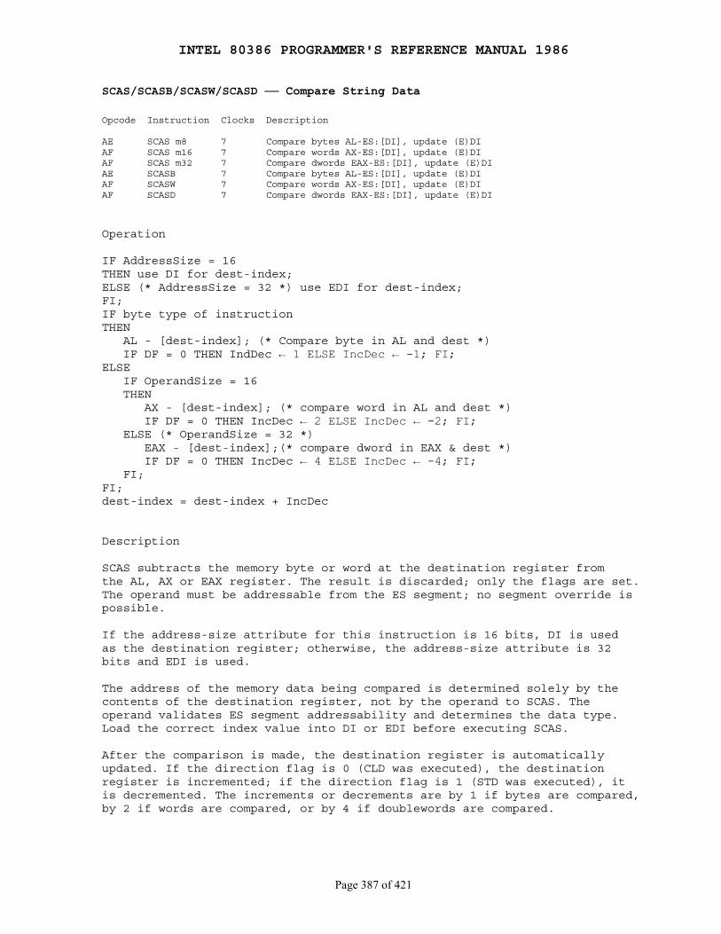
INTEL 80386 PROGRAMMER'S REFERENCE MANUAL 1986
Page 387 of 421
SCAS/SCASB/SCASW/SCASD ── Compare String Data
Opcode Instruction Clocks Description
AE SCAS m8 7 Compare bytes AL-ES:[DI], update (E)DIAF SCAS m16 7 Compare words AX-ES:[DI], update (E)DIAF SCAS m32 7 Compare dwords EAX-ES:[DI], update (E)DIAE SCASB 7 Compare bytes AL-ES:[DI], update (E)DIAF SCASW 7 Compare words AX-ES:[DI], update (E)DIAF SCASD 7 Compare dwords EAX-ES:[DI], update (E)DI
Operation
IF AddressSize = 16THEN use DI for dest-index;ELSE (* AddressSize = 32 *) use EDI for dest-index;FI;IF byte type of instructionTHEN AL - [dest-index]; (* Compare byte in AL and dest *) IF DF = 0 THEN IndDec ← 1 ELSE IncDec ← -1; FI;ELSE IF OperandSize = 16 THEN AX - [dest-index]; (* compare word in AL and dest *) IF DF = 0 THEN IncDec ← 2 ELSE IncDec ← -2; FI; ELSE (* OperandSize = 32 *) EAX - [dest-index];(* compare dword in EAX & dest *) IF DF = 0 THEN IncDec ← 4 ELSE IncDec ← -4; FI; FI;FI;dest-index = dest-index + IncDec
Description
SCAS subtracts the memory byte or word at the destination register fromthe AL, AX or EAX register. The result is discarded; only the flags are set.The operand must be addressable from the ES segment; no segment override ispossible.
If the address-size attribute for this instruction is 16 bits, DI is usedas the destination register; otherwise, the address-size attribute is 32bits and EDI is used.
The address of the memory data being compared is determined solely by thecontents of the destination register, not by the operand to SCAS. Theoperand validates ES segment addressability and determines the data type.Load the correct index value into DI or EDI before executing SCAS.
After the comparison is made, the destination register is automaticallyupdated. If the direction flag is 0 (CLD was executed), the destinationregister is incremented; if the direction flag is 1 (STD was executed), itis decremented. The increments or decrements are by 1 if bytes are compared,by 2 if words are compared, or by 4 if doublewords are compared.
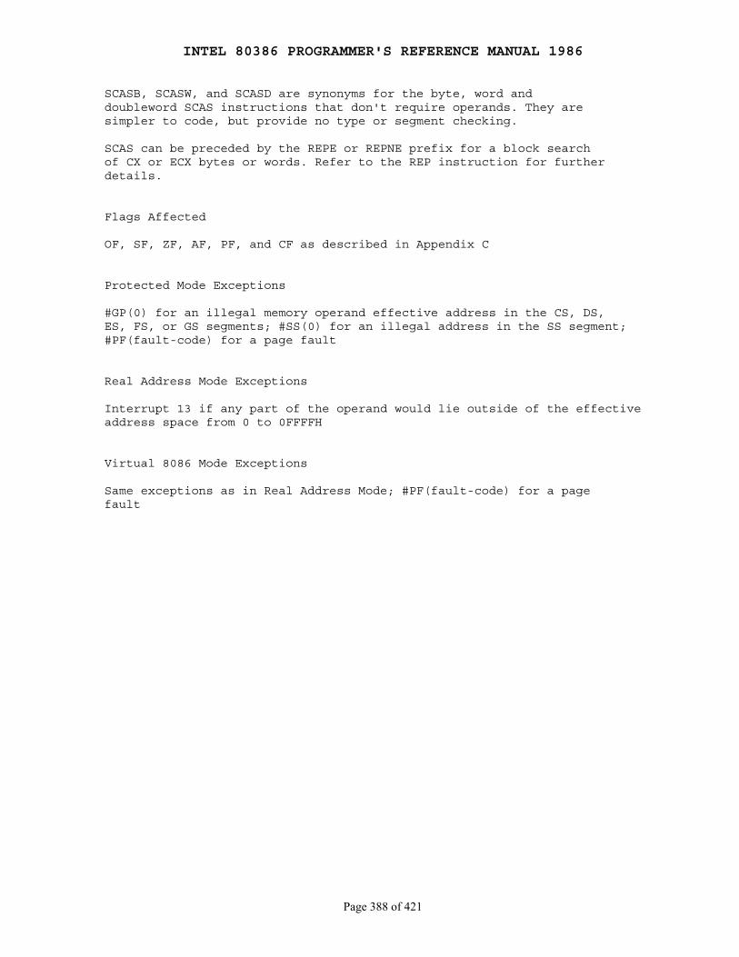
INTEL 80386 PROGRAMMER'S REFERENCE MANUAL 1986
Page 388 of 421
SCASB, SCASW, and SCASD are synonyms for the byte, word anddoubleword SCAS instructions that don't require operands. They aresimpler to code, but provide no type or segment checking.
SCAS can be preceded by the REPE or REPNE prefix for a block searchof CX or ECX bytes or words. Refer to the REP instruction for furtherdetails.
Flags Affected
OF, SF, ZF, AF, PF, and CF as described in Appendix C
Protected Mode Exceptions
#GP(0) for an illegal memory operand effective address in the CS, DS,ES, FS, or GS segments; #SS(0) for an illegal address in the SS segment;#PF(fault-code) for a page fault
Real Address Mode Exceptions
Interrupt 13 if any part of the operand would lie outside of the effectiveaddress space from 0 to 0FFFFH
Virtual 8086 Mode Exceptions
Same exceptions as in Real Address Mode; #PF(fault-code) for a pagefault
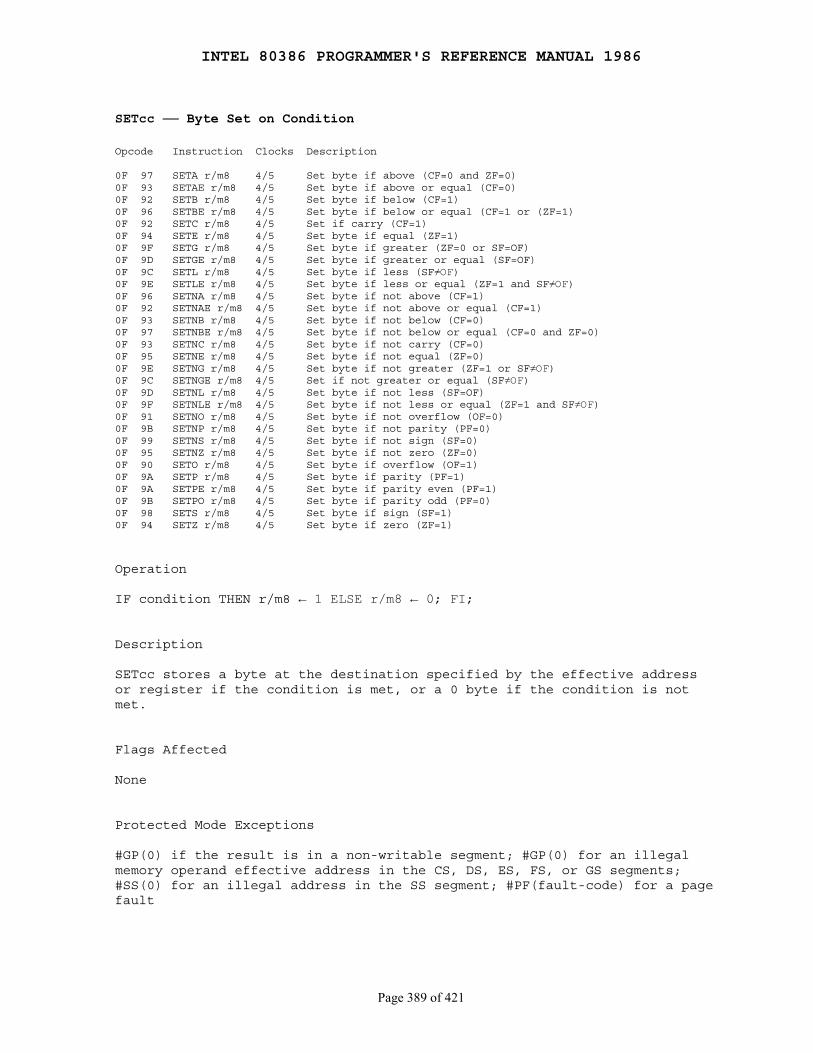
INTEL 80386 PROGRAMMER'S REFERENCE MANUAL 1986
Page 389 of 421
SETcc ── Byte Set on Condition
Opcode Instruction Clocks Description
0F 97 SETA r/m8 4/5 Set byte if above (CF=0 and ZF=0)0F 93 SETAE r/m8 4/5 Set byte if above or equal (CF=0)0F 92 SETB r/m8 4/5 Set byte if below (CF=1)0F 96 SETBE r/m8 4/5 Set byte if below or equal (CF=1 or (ZF=1)0F 92 SETC r/m8 4/5 Set if carry (CF=1)0F 94 SETE r/m8 4/5 Set byte if equal (ZF=1)0F 9F SETG r/m8 4/5 Set byte if greater (ZF=0 or SF=OF)0F 9D SETGE r/m8 4/5 Set byte if greater or equal (SF=OF)0F 9C SETL r/m8 4/5 Set byte if less (SF≠OF)0F 9E SETLE r/m8 4/5 Set byte if less or equal (ZF=1 and SF≠OF)0F 96 SETNA r/m8 4/5 Set byte if not above (CF=1)0F 92 SETNAE r/m8 4/5 Set byte if not above or equal (CF=1)0F 93 SETNB r/m8 4/5 Set byte if not below (CF=0)0F 97 SETNBE r/m8 4/5 Set byte if not below or equal (CF=0 and ZF=0)0F 93 SETNC r/m8 4/5 Set byte if not carry (CF=0)0F 95 SETNE r/m8 4/5 Set byte if not equal (ZF=0)0F 9E SETNG r/m8 4/5 Set byte if not greater (ZF=1 or SF≠OF)0F 9C SETNGE r/m8 4/5 Set if not greater or equal (SF≠OF)0F 9D SETNL r/m8 4/5 Set byte if not less (SF=OF)0F 9F SETNLE r/m8 4/5 Set byte if not less or equal (ZF=1 and SF≠OF)0F 91 SETNO r/m8 4/5 Set byte if not overflow (OF=0)0F 9B SETNP r/m8 4/5 Set byte if not parity (PF=0)0F 99 SETNS r/m8 4/5 Set byte if not sign (SF=0)0F 95 SETNZ r/m8 4/5 Set byte if not zero (ZF=0)0F 90 SETO r/m8 4/5 Set byte if overflow (OF=1)0F 9A SETP r/m8 4/5 Set byte if parity (PF=1)0F 9A SETPE r/m8 4/5 Set byte if parity even (PF=1)0F 9B SETPO r/m8 4/5 Set byte if parity odd (PF=0)0F 98 SETS r/m8 4/5 Set byte if sign (SF=1)0F 94 SETZ r/m8 4/5 Set byte if zero (ZF=1)
Operation
IF condition THEN r/m8 ← 1 ELSE r/m8 ← 0; FI;
Description
SETcc stores a byte at the destination specified by the effective addressor register if the condition is met, or a 0 byte if the condition is notmet.
Flags Affected
None
Protected Mode Exceptions
#GP(0) if the result is in a non-writable segment; #GP(0) for an illegalmemory operand effective address in the CS, DS, ES, FS, or GS segments;#SS(0) for an illegal address in the SS segment; #PF(fault-code) for a pagefault

INTEL 80386 PROGRAMMER'S REFERENCE MANUAL 1986
Page 390 of 421
Real Address Mode Exceptions
Interrupt 13 if any part of the operand would lie outside of the effectiveaddress space from 0 to 0FFFFH
Virtual 8086 Mode Exceptions
Same exceptions as in Real Address Mode; #PF(fault-code) for a pagefault

INTEL 80386 PROGRAMMER'S REFERENCE MANUAL 1986
Page 391 of 421
SGDT/SIDT ── Store Global/Interrupt Descriptor Table Register
Opcode Instruction Clocks Description
0F 01 /0 SGDT m 9 Store GDTR to m0F 01 /1 SIDT m 9 Store IDTR to m
Operation
DEST ← 48-bit BASE/LIMIT register contents;
Description
SGDT/SIDT copies the contents of the descriptor table register the sixbytes of memory indicated by the operand. The LIMIT field of theregister is assigned to the first word at the effective address. If theoperand-size attribute is 32 bits, the next three bytes are assigned theBASE field of the register, and the fourth byte is written with zero. Thelast byte is undefined. Otherwise, if the operand-size attribute is 16bits, the next 4 bytes are assigned the 32-bit BASE field of the register.
SGDT and SIDT are used only in operating system software; they arenot used in application programs.
Flags Affected
None
Protected Mode Exceptions
Interrupt 6 if the destination operand is a register; #GP(0) if thedestination is in a nonwritable segment; #GP(0) for an illegal memoryoperand effective address in the CS, DS, ES, FS, or GS segments; #SS(0) foran illegal address in the SS segment; #PF(fault-code) for a page fault
Real Address Mode Exceptions
Interrupt 6 if the destination operand is a register; Interrupt 13 if anypart of the operand would lie outside of the effective address space from0 to 0FFFFH
Virtual 8086 Mode Exceptions
Same exceptions as in Real Address Mode; #PF(fault-code) for a pagefault
Compatability Note
The 16-bit forms of the SGDT/SIDT instructions are compatible withthe 80286, if the value in the upper eight bits is not referenced. The80286 stores 1's in these upper bits, whereas the 80386 stores 0's if theoperand-size attribute is 16 bits. These bits were specified as undefinedby the SGDT/SIDT instructions in the iAPX 286 Programmer'sReference Manual.
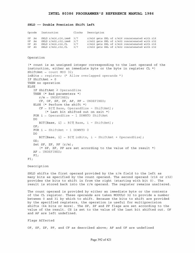
INTEL 80386 PROGRAMMER'S REFERENCE MANUAL 1986
Page 392 of 421
SHLD ── Double Precision Shift Left
Opcode Instruction Clocks Description
0F A4 SHLD r/m16,r16,imm8 3/7 r/m16 gets SHL of r/m16 concatenated with r160F A4 SHLD r/m32,r32,imm8 3/7 r/m32 gets SHL of r/m32 concatenated with r320F A5 SHLD r/m16,r16,CL 3/7 r/m16 gets SHL of r/m16 concatenated with r160F A5 SHLD r/m32,r32,CL 3/7 r/m32 gets SHL of r/m32 concatenated with r32
Operation
(* count is an unsigned integer corresponding to the last operand of theinstruction, either an immediate byte or the byte in register CL *)ShiftAmt ← count MOD 32;inBits ← register; (* Allow overlapped operands *)IF ShiftAmt = 0THEN no operationELSE IF ShiftAmt ≥ OperandSize THEN (* Bad parameters *) r/m ← UNDEFINED; CF, OF, SF, ZF, AF, PF ← UNDEFINED; ELSE (* Perform the shift *) CF ← BIT[Base, OperandSize - ShiftAmt]; (* Last bit shifted out on exit *) FOR i ← OperandSize - 1 DOWNTO ShiftAmt DO BIT[Base, i] ← BIT[Base, i - ShiftAmt]; OF; FOR i ← ShiftAmt - 1 DOWNTO 0 DO BIT[Base, i] ← BIT[inBits, i - ShiftAmt + OperandSize]; OD; Set SF, ZF, PF (r/m); (* SF, ZF, PF are set according to the value of the result *) AF ← UNDEFINED; FI;FI;
Description
SHLD shifts the first operand provided by the r/m field to the left asmany bits as specified by the count operand. The second operand (r16 or r32)provides the bits to shift in from the right (starting with bit 0). Theresult is stored back into the r/m operand. The register remains unaltered.
The count operand is provided by either an immediate byte or the contentsof the CL register. These operands are taken MODULO 32 to provide a numberbetween 0 and 31 by which to shift. Because the bits to shift are providedby the specified registers, the operation is useful for multiprecisionshifts (64 bits or more). The SF, ZF and PF flags are set according to thevalue of the result. CS is set to the value of the last bit shifted out. OFand AF are left undefined.
Flags Affected
OF, SF, ZF, PF, and CF as described above; AF and OF are undefined
INTEL 80386 PROGRAMMER'S REFERENCE MANUAL 1986
Page 393 of 421
Protected Mode Exceptions
#GP(0) if the result is in a nonwritable segment; #GP(0) for an illegalmemory operand effective address in the CS, DS, ES, FS, or GS segments;#SS(0) for an illegal address in the SS segment; #PF(fault-code) for a pagefault
Real Address Mode Exceptions
Interrupt 13 if any part of the operand would lie outside of the effectiveaddress space from 0 to 0FFFFH
Virtual 8086 Mode Exceptions
Same exceptions as in Real Address Mode; #PF(fault-code) for a page fault

INTEL 80386 PROGRAMMER'S REFERENCE MANUAL 1986
Page 394 of 421
SHRD ── Double Precision Shift Right
Opcode Instruction Clocks Description
0F AC SHRD r/m16,r16,imm8 3/7 r/m16 gets SHR of r/m16 concatenated with r160F AC SHRD r/m32,r32,imm8 3/7 r/m32 gets SHR of r/m32 with r320F AD SHRD r/m16,r16,CL 3/7 r/m16 gets SHR of r/m16 concatenated with r160F AD SHRD r/m32,r32,CL 3/7 r/m32 gets SHR of r/m32 concatenated with r32
Operation
(* count is an unsigned integer corresponding to the last operand of theinstruction, either an immediate byte or the byte in register CL *)ShiftAmt ← count MOD 32;inBits ← register; (* Allow overlapped operands *)IF ShiftAmt = 0THEN no operationELSE IF ShiftAmt ≥ OperandSize THEN (* Bad parameters *) r/m ← UNDEFINED; CF, OF, SF, ZF, AF, PF ← UNDEFINED; ELSE (* Perform the shift *) CF ← BIT[r/m, ShiftAmt - 1]; (* last bit shifted out on exit *) FOR i ← 0 TO OperandSize - 1 - ShiftAmt DO BIT[r/m, i] ← BIT[r/m, i - ShiftAmt]; OD; FOR i ← OperandSize - ShiftAmt TO OperandSize - 1 DO BIT[r/m,i] ← BIT[inBits,i+ShiftAmt - OperandSize]; OD; Set SF, ZF, PF (r/m); (* SF, ZF, PF are set according to the value of the result *) Set SF, ZF, PF (r/m); AF ← UNDEFINED; FI;FI;
Description
SHRD shifts the first operand provided by the r/m field to the right as manybits as specified by the count operand. The second operand (r16 or r32)provides the bits to shift in from the left (starting with bit 31). Theresult is stored back into the r/m operand. The register remains unaltered.
The count operand is provided by either an immediate byte or the contentsof the CL register. These operands are taken MODULO 32 to provide a numberbetween 0 and 31 by which to shift. Because the bits to shift are providedby the specified register, the operation is useful for multi-precisionshifts (64 bits or more). The SF, ZF and PF flags are set according to thevalue of the result. CS is set to the value of the last bit shifted out. OFand AF are left undefined.
INTEL 80386 PROGRAMMER'S REFERENCE MANUAL 1986
Page 395 of 421
Flags Affected
OF, SF, ZF, PF, and CF as described above; AF and OF are undefined
Protected Mode Exceptions
#GP(0) if the result is in a nonwritable segment; #GP(0) for an illegalmemory operand effective address in the CS, DS, ES, FS, or GSsegments; #SS(0) for an illegal address in the SS segment; #PF(fault-code)for a page fault
Real Address Mode Exceptions
Interrupt 13 if any part of the operand would lie outside of the effectiveaddress space from 0 to 0FFFFH
Virtual 8086 Mode Exceptions
Same exceptions as in Real Address Mode; #PF(fault-code) for a pagefault
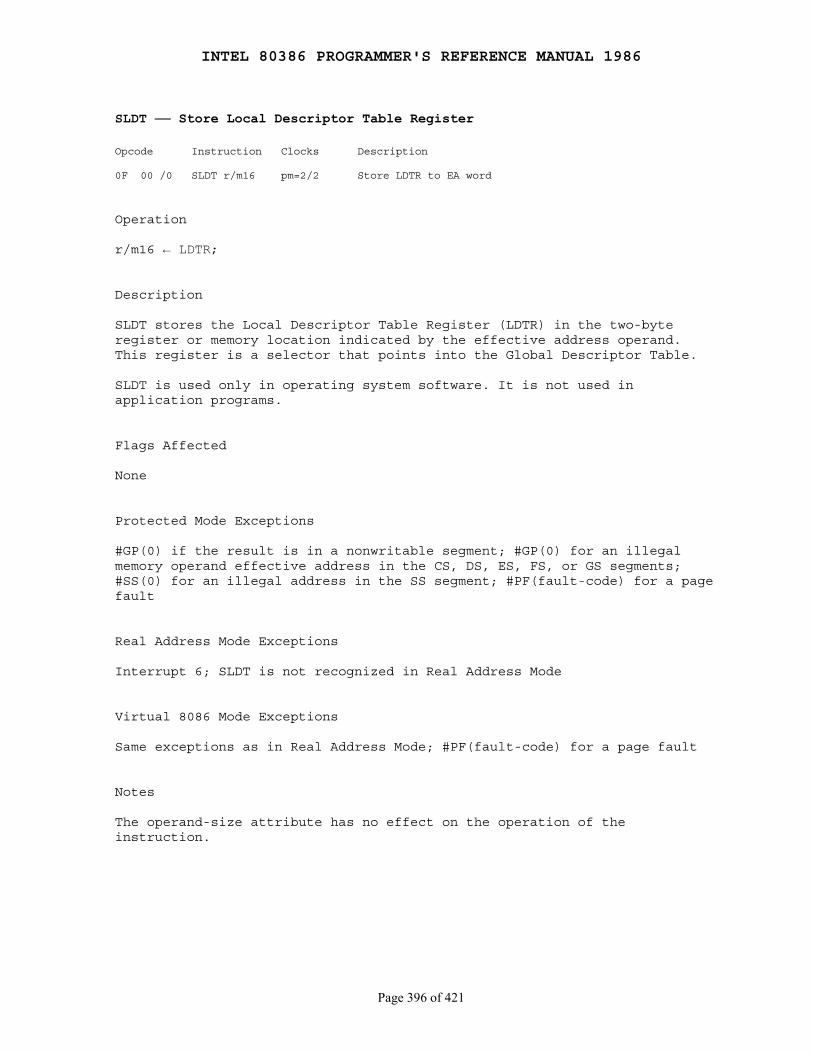
INTEL 80386 PROGRAMMER'S REFERENCE MANUAL 1986
Page 396 of 421
SLDT ── Store Local Descriptor Table Register
Opcode Instruction Clocks Description
0F 00 /0 SLDT r/m16 pm=2/2 Store LDTR to EA word
Operation
r/m16 ← LDTR;
Description
SLDT stores the Local Descriptor Table Register (LDTR) in the two-byteregister or memory location indicated by the effective address operand.This register is a selector that points into the Global Descriptor Table.
SLDT is used only in operating system software. It is not used inapplication programs.
Flags Affected
None
Protected Mode Exceptions
#GP(0) if the result is in a nonwritable segment; #GP(0) for an illegalmemory operand effective address in the CS, DS, ES, FS, or GS segments;#SS(0) for an illegal address in the SS segment; #PF(fault-code) for a pagefault
Real Address Mode Exceptions
Interrupt 6; SLDT is not recognized in Real Address Mode
Virtual 8086 Mode Exceptions
Same exceptions as in Real Address Mode; #PF(fault-code) for a page fault
Notes
The operand-size attribute has no effect on the operation of theinstruction.
INTEL 80386 PROGRAMMER'S REFERENCE MANUAL 1986
Page 397 of 421
SMSW ── Store Machine Status Word
Opcode Instruction Clocks Description
0F 01 /4 SMSW r/m16 2/3,pm=2/2 Store machine status word to EA word
Operation
r/m16 ← MSW;
Description
SMSW stores the machine status word (part of CR0) in the two-byte registeror memory location indicated by the effective address operand.
Flags Affected
None
Protected Mode Exceptions
#GP(0) if the result is in a nonwritable segment; #GP(0) for an illegalmemory operand effective address in the CS, DS, ES, FS, or GS segments;#SS(0) for an illegal address in the SS segment; #PF(fault-code) for a pagefault
Real Address Mode Exceptions
Interrupt 13 if any part of the operand would lie outside of the effectiveaddress space from 0 to 0FFFFH
Virtual 8086 Mode Exceptions
Same exceptions as in Real Address Mode; #PF(fault-code) for a page fault
Notes
This instruction is provided for compatibility with the 80286; 80386programs should use MOV ..., CR0.

INTEL 80386 PROGRAMMER'S REFERENCE MANUAL 1986
Page 398 of 421
STC ── Set Carry Flag
Opcode Instruction Clocks Description
F9 STC 2 Set carry flag
Operation
CF ← 1;
Description
STC sets the carry flag to 1.
Flags Affected
CF = 1
Protected Mode Exceptions
None
Real Address Mode Exceptions
None
Virtual 8086 Mode Exceptions
None
INTEL 80386 PROGRAMMER'S REFERENCE MANUAL 1986
Page 399 of 421
STD ── Set Direction Flag
Opcode Instruction Clocks Description
FD STD 2 Set direction flag so (E)SI and/or (E)DI decrement
Operation
DF ← 1;
Description
STD sets the direction flag to 1, causing all subsequent string operationsto decrement the index registers, (E)SI and/or (E)DI, on which theyoperate.
Flags Affected
DF = 1
Protected Mode Exceptions
None
Real Address Mode Exceptions
None
Virtual 8086 Mode Exceptions
None
INTEL 80386 PROGRAMMER'S REFERENCE MANUAL 1986
Page 400 of 421
STI ── Set Interrupt Flag
Opcode Instruction Clocks Description
F13 STI 3 Set interrupt flag; interrupts enabled at the end of the next instruction
Operation
IF ← 1
Description
STI sets the interrupt flag to 1. The 80386 then responds to externalinterrupts after executing the next instruction if the next instructionallows the interrupt flag to remain enabled. If external interrupts aredisabled and you code STI, RET (such as at the end of a subroutine),the RET is allowed to execute before external interrupts are recognized.Also, if external interrupts are disabled and you code STI, CLI, thenexternal interrupts are not recognized because the CLI instruction clearsthe interrupt flag during its execution.
Flags Affected
IF = 1
Protected Mode Exceptions
#GP(0) if the current privilege level is greater (has less privilege) thanthe I/O privilege level
Real Address Mode Exceptions
None
Virtual 8086 Mode Exceptions
None

INTEL 80386 PROGRAMMER'S REFERENCE MANUAL 1986
Page 401 of 421
STOS/STOSB/STOSW/STOSD ── Store String Data
Opcode Instruction Clocks Description
AA STOS m8 4 Store AL in byte ES:[(E)DI], update (E)DIAB STOS m16 4 Store AX in word ES:[(E)DI], update (E)DIAB STOS m32 4 Store EAX in dword ES:[(E)DI], update (E)DIAA STOSB 4 Store AL in byte ES:[(E)DI], update (E)DIAB STOSW 4 Store AX in word ES:[(E)DI], update (E)DIAB STOSD 4 Store EAX in dword ES:[(E)DI], update (E)DI
Operation
IF AddressSize = 16THEN use ES:DI for DestRegELSE (* AddressSize = 32 *) use ES:EDI for DestReg;FI;IF byte type of instructionTHEN (ES:DestReg) ← AL; IF DF = 0 THEN DestReg ← DestReg + 1; ELSE DestReg ← DestReg - 1; FI;ELSE IF OperandSize = 16 THEN (ES:DestReg) ← AX; IF DF = 0 THEN DestReg ← DestReg + 2; ELSE DestReg ← DestReg - 2; FI; ELSE (* OperandSize = 32 *) (ES:DestReg) ← EAX; IF DF = 0 THEN DestReg ← DestReg + 4; ELSE DestReg ← DestReg - 4; FI; FI;FI;
Description
STOS transfers the contents of all AL, AX, or EAX register to the memorybyte or word given by the destination register relative to the ES segment.The destination register is DI for an address-size attribute of 16 bits orEDI for an address-size attribute of 32 bits.
The destination operand must be addressable from the ES register. A segmentoverride is not possible.
The address of the destination is determined by the contents of thedestination register, not by the explicit operand of STOS. This operand isused only to validate ES segment addressability and to determine the datatype. Load the correct index value into the destination register beforeexecuting STOS.

INTEL 80386 PROGRAMMER'S REFERENCE MANUAL 1986
Page 402 of 421
After the transfer is made, DI is automatically updated. If the directionflag is 0 (CLD was executed), DI is incremented; if the direction flag is1 (STD was executed), DI is decremented. DI is incremented or decremented by1 if a byte is stored, by 2 if a word is stored, or by 4 if a doubleword isstored.
STOSB, STOSW, and STOSD are synonyms for the byte, word, and doubleword STOSinstructions, that do not require an operand. They are simpler to use, butprovide no type or segment checking.
STOS can be preceded by the REP prefix for a block fill of CX or ECX bytes,words, or doublewords. Refer to the REP instruction for further details.
Flags Affected
None
Protected Mode Exceptions
#GP(0) if the result is in a nonwritable segment; #GP(0) for an illegalmemory operand effective address in the CS, DS, ES, FS, or GS segments;#SS(0) for an illegal address in the SS segment; #PF(fault-code) for a pagefault
Real Address Mode Exceptions
Interrupt 13 if any part of the operand would lie outside of the effectiveaddress space from 0 to 0FFFFH
Virtual 8086 Mode Exceptions
Same exceptions as in Real Address Mode; #PF(fault-code) for a page fault
INTEL 80386 PROGRAMMER'S REFERENCE MANUAL 1986
Page 403 of 421
STR ── Store Task Register
Opcode Instruction Clocks Description
0F 00 /1 STR r/m16 pm=23/27 Load EA word into task register
Operation
r/m ← task register;
Description
The contents of the task register are copied to the two-byte register ormemory location indicated by the effective address operand.
STR is used only in operating system software. It is not used in applicationprograms.
Flags Affected
None
Protected Mode Exceptions
#GP(0) if the result is in a nonwritable segment; #GP(0) for an illegalmemory operand effective address in the CS, DS, ES, FS, or GS segments;#SS(0) for an illegal address in the SS segment; #PF(fault-code) for a pagefault
Real Address Mode Exceptions
Interrupt 6; STR is not recognized in Real Address Mode
Virtual 8086 Mode Exceptions
Same exceptions as in Real Address Mode
Notes
The operand-size attribute has no effect on this instruction.
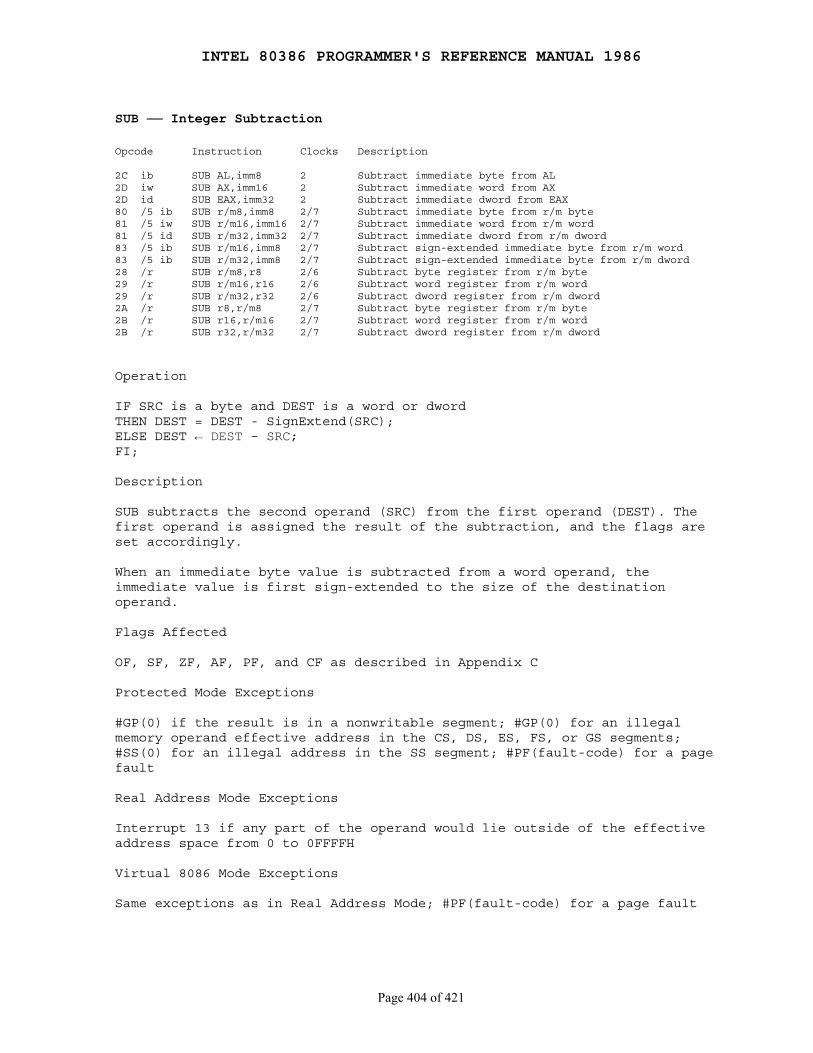
INTEL 80386 PROGRAMMER'S REFERENCE MANUAL 1986
Page 404 of 421
SUB ── Integer Subtraction
Opcode Instruction Clocks Description
2C ib SUB AL,imm8 2 Subtract immediate byte from AL2D iw SUB AX,imm16 2 Subtract immediate word from AX2D id SUB EAX,imm32 2 Subtract immediate dword from EAX80 /5 ib SUB r/m8,imm8 2/7 Subtract immediate byte from r/m byte81 /5 iw SUB r/m16,imm16 2/7 Subtract immediate word from r/m word81 /5 id SUB r/m32,imm32 2/7 Subtract immediate dword from r/m dword83 /5 ib SUB r/m16,imm8 2/7 Subtract sign-extended immediate byte from r/m word83 /5 ib SUB r/m32,imm8 2/7 Subtract sign-extended immediate byte from r/m dword28 /r SUB r/m8,r8 2/6 Subtract byte register from r/m byte29 /r SUB r/m16,r16 2/6 Subtract word register from r/m word29 /r SUB r/m32,r32 2/6 Subtract dword register from r/m dword2A /r SUB r8,r/m8 2/7 Subtract byte register from r/m byte2B /r SUB r16,r/m16 2/7 Subtract word register from r/m word2B /r SUB r32,r/m32 2/7 Subtract dword register from r/m dword
Operation
IF SRC is a byte and DEST is a word or dwordTHEN DEST = DEST - SignExtend(SRC);ELSE DEST ← DEST - SRC;FI;
Description
SUB subtracts the second operand (SRC) from the first operand (DEST). Thefirst operand is assigned the result of the subtraction, and the flags areset accordingly.
When an immediate byte value is subtracted from a word operand, theimmediate value is first sign-extended to the size of the destinationoperand.
Flags Affected
OF, SF, ZF, AF, PF, and CF as described in Appendix C
Protected Mode Exceptions
#GP(0) if the result is in a nonwritable segment; #GP(0) for an illegalmemory operand effective address in the CS, DS, ES, FS, or GS segments;#SS(0) for an illegal address in the SS segment; #PF(fault-code) for a pagefault
Real Address Mode Exceptions
Interrupt 13 if any part of the operand would lie outside of the effectiveaddress space from 0 to 0FFFFH
Virtual 8086 Mode Exceptions
Same exceptions as in Real Address Mode; #PF(fault-code) for a page fault
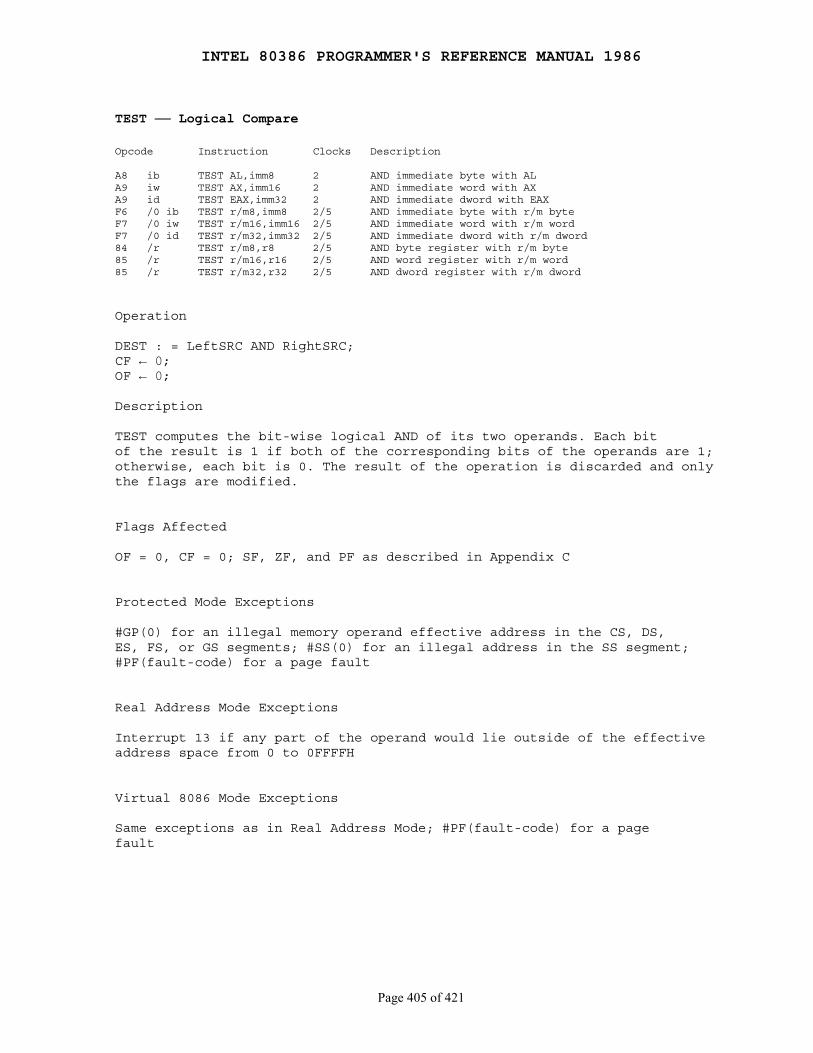
INTEL 80386 PROGRAMMER'S REFERENCE MANUAL 1986
Page 405 of 421
TEST ── Logical Compare
Opcode Instruction Clocks Description
A8 ib TEST AL,imm8 2 AND immediate byte with ALA9 iw TEST AX,imm16 2 AND immediate word with AXA9 id TEST EAX,imm32 2 AND immediate dword with EAXF6 /0 ib TEST r/m8,imm8 2/5 AND immediate byte with r/m byteF7 /0 iw TEST r/m16,imm16 2/5 AND immediate word with r/m wordF7 /0 id TEST r/m32,imm32 2/5 AND immediate dword with r/m dword84 /r TEST r/m8,r8 2/5 AND byte register with r/m byte85 /r TEST r/m16,r16 2/5 AND word register with r/m word85 /r TEST r/m32,r32 2/5 AND dword register with r/m dword
Operation
DEST : = LeftSRC AND RightSRC;CF ← 0;OF ← 0;
Description
TEST computes the bit-wise logical AND of its two operands. Each bitof the result is 1 if both of the corresponding bits of the operands are 1;otherwise, each bit is 0. The result of the operation is discarded and onlythe flags are modified.
Flags Affected
OF = 0, CF = 0; SF, ZF, and PF as described in Appendix C
Protected Mode Exceptions
#GP(0) for an illegal memory operand effective address in the CS, DS,ES, FS, or GS segments; #SS(0) for an illegal address in the SS segment;#PF(fault-code) for a page fault
Real Address Mode Exceptions
Interrupt 13 if any part of the operand would lie outside of the effectiveaddress space from 0 to 0FFFFH
Virtual 8086 Mode Exceptions
Same exceptions as in Real Address Mode; #PF(fault-code) for a pagefault
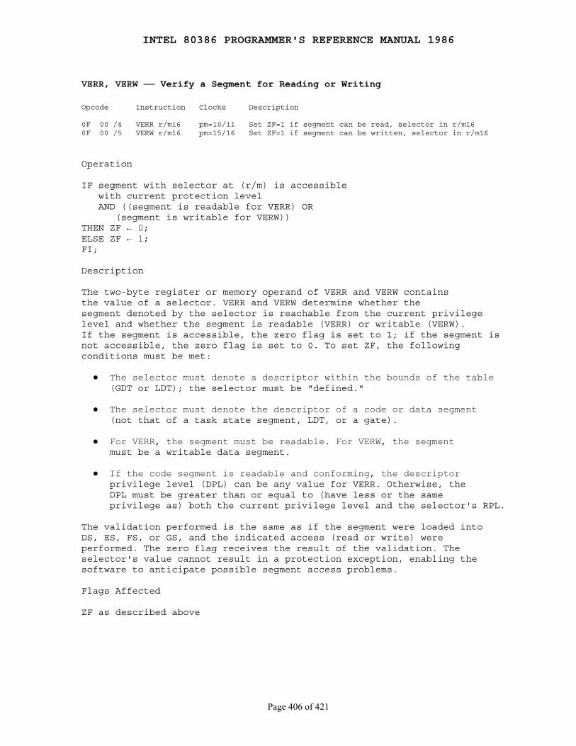
INTEL 80386 PROGRAMMER'S REFERENCE MANUAL 1986
Page 406 of 421
VERR, VERW ── Verify a Segment for Reading or Writing
Opcode Instruction Clocks Description
0F 00 /4 VERR r/m16 pm=10/11 Set ZF=1 if segment can be read, selector in r/m160F 00 /5 VERW r/m16 pm=15/16 Set ZF=1 if segment can be written, selector in r/m16
Operation
IF segment with selector at (r/m) is accessible with current protection level AND ((segment is readable for VERR) OR (segment is writable for VERW))THEN ZF ← 0;ELSE ZF ← 1;FI;
Description
The two-byte register or memory operand of VERR and VERW containsthe value of a selector. VERR and VERW determine whether thesegment denoted by the selector is reachable from the current privilegelevel and whether the segment is readable (VERR) or writable (VERW).If the segment is accessible, the zero flag is set to 1; if the segment isnot accessible, the zero flag is set to 0. To set ZF, the followingconditions must be met:
● The selector must denote a descriptor within the bounds of the table (GDT or LDT); the selector must be "defined."
● The selector must denote the descriptor of a code or data segment (not that of a task state segment, LDT, or a gate).
● For VERR, the segment must be readable. For VERW, the segment must be a writable data segment.
● If the code segment is readable and conforming, the descriptor privilege level (DPL) can be any value for VERR. Otherwise, the DPL must be greater than or equal to (have less or the same privilege as) both the current privilege level and the selector's RPL.
The validation performed is the same as if the segment were loaded intoDS, ES, FS, or GS, and the indicated access (read or write) wereperformed. The zero flag receives the result of the validation. Theselector's value cannot result in a protection exception, enabling thesoftware to anticipate possible segment access problems.
Flags Affected
ZF as described above

INTEL 80386 PROGRAMMER'S REFERENCE MANUAL 1986
Page 407 of 421
Protected Mode Exceptions
Faults generated by illegal addressing of the memory operand thatcontains the selector, the selector is not loaded into any segmentregister, and no faults attributable to the selector operand are generated
#GP(0) for an illegal memory operand effective address in the CS, DS,ES, FS, or GS segments; #SS(0) for an illegal address in the SS segment;#PF(fault-code) for a page fault
Real Address Mode Exceptions
Interrupt 6; VERR and VERW are not recognized in Real Address Mode
Virtual 8086 Mode Exceptions
Same exceptions as in Real Address Mode; #PF(fault-code) for a pagefault
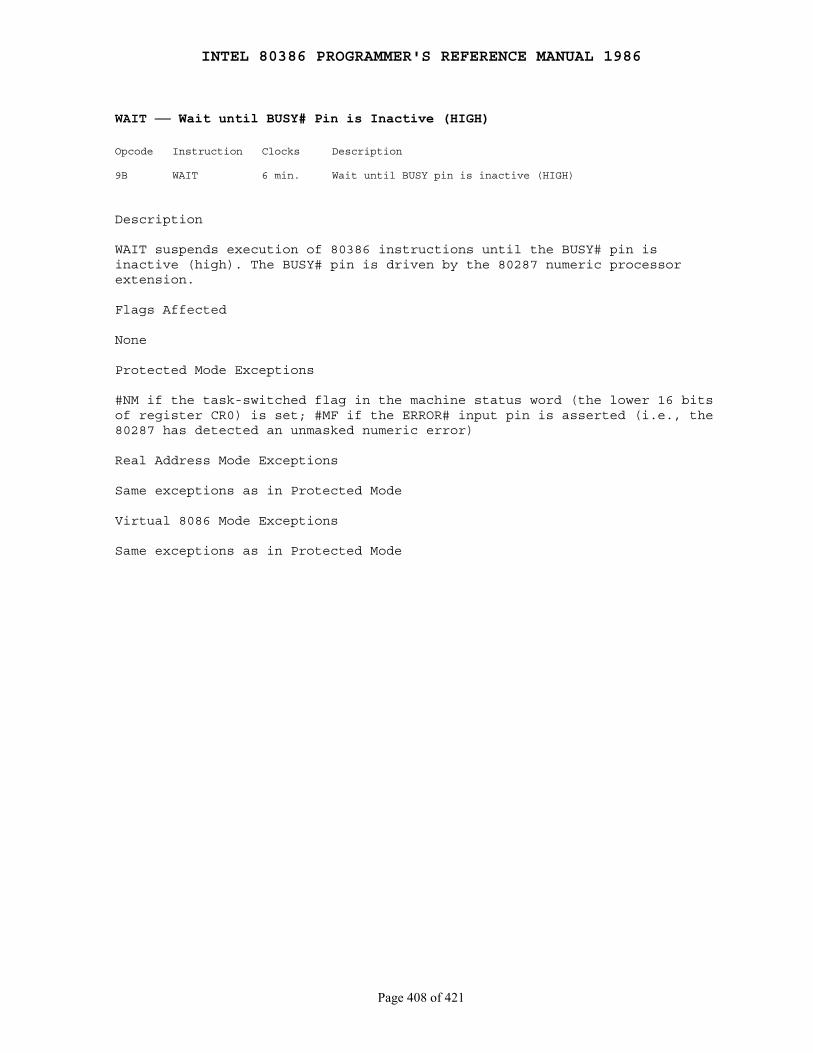
INTEL 80386 PROGRAMMER'S REFERENCE MANUAL 1986
Page 408 of 421
WAIT ── Wait until BUSY# Pin is Inactive (HIGH)
Opcode Instruction Clocks Description
9B WAIT 6 min. Wait until BUSY pin is inactive (HIGH)
Description
WAIT suspends execution of 80386 instructions until the BUSY# pin isinactive (high). The BUSY# pin is driven by the 80287 numeric processorextension.
Flags Affected
None
Protected Mode Exceptions
#NM if the task-switched flag in the machine status word (the lower 16 bitsof register CR0) is set; #MF if the ERROR# input pin is asserted (i.e., the80287 has detected an unmasked numeric error)
Real Address Mode Exceptions
Same exceptions as in Protected Mode
Virtual 8086 Mode Exceptions
Same exceptions as in Protected Mode
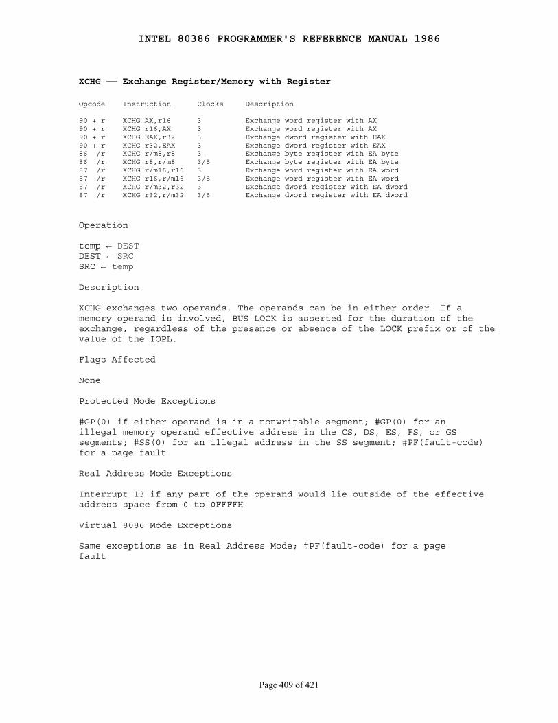
INTEL 80386 PROGRAMMER'S REFERENCE MANUAL 1986
Page 409 of 421
XCHG ── Exchange Register/Memory with Register
Opcode Instruction Clocks Description
90 + r XCHG AX,r16 3 Exchange word register with AX90 + r XCHG r16,AX 3 Exchange word register with AX90 + r XCHG EAX,r32 3 Exchange dword register with EAX90 + r XCHG r32,EAX 3 Exchange dword register with EAX86 /r XCHG r/m8,r8 3 Exchange byte register with EA byte86 /r XCHG r8,r/m8 3/5 Exchange byte register with EA byte87 /r XCHG r/m16,r16 3 Exchange word register with EA word87 /r XCHG r16,r/m16 3/5 Exchange word register with EA word87 /r XCHG r/m32,r32 3 Exchange dword register with EA dword87 /r XCHG r32,r/m32 3/5 Exchange dword register with EA dword
Operation
temp ← DESTDEST ← SRCSRC ← temp
Description
XCHG exchanges two operands. The operands can be in either order. If amemory operand is involved, BUS LOCK is asserted for the duration of theexchange, regardless of the presence or absence of the LOCK prefix or of thevalue of the IOPL.
Flags Affected
None
Protected Mode Exceptions
#GP(0) if either operand is in a nonwritable segment; #GP(0) for anillegal memory operand effective address in the CS, DS, ES, FS, or GSsegments; #SS(0) for an illegal address in the SS segment; #PF(fault-code)for a page fault
Real Address Mode Exceptions
Interrupt 13 if any part of the operand would lie outside of the effectiveaddress space from 0 to 0FFFFH
Virtual 8086 Mode Exceptions
Same exceptions as in Real Address Mode; #PF(fault-code) for a pagefault

INTEL 80386 PROGRAMMER'S REFERENCE MANUAL 1986
Page 410 of 421
XLAT/XLATB ── Table Look-up Translation
D7 XLAT m8 5 Set AL to memory byte DS:[(E)BX + unsigned AL]D7 XLATB 5 Set AL to memory byte DS:[(E)BX + unsigned AL]
Operation
IF AddressSize = 16THEN AL ← (BX + ZeroExtend(AL))ELSE (* AddressSize = 32 *) AL ← (EBX + ZeroExtend(AL));FI;
Description
XLAT changes the AL register from the table index to the table entry. ALshould be the unsigned index into a table addressed by DS:BX (for anaddress-size attribute of 16 bits) or DS:EBX (for an address-size attributeof 32 bits).
The operand to XLAT allows for the possibility of a segment override. XLATuses the contents of BX even if they differ from the offset of the operand.The offset of the operand should have been moved intoBX/EBX with a previousinstruction.
The no-operand form, XLATB, can be used if the BX/EBX table will alwaysreside in the DS segment.
Flags Affected
None
Protected Mode Exceptions
#GP(0) for an illegal memory operand effective address in the CS, DS, ES,FS, or GS segments; #SS(0) for an illegal address in the SS segment;#PF(fault-code) for a page fault
Real Address Mode Exceptions
Interrupt 13 if any part of the operand would lie outside of the effectiveaddress space from 0 to 0FFFFH
Virtual 8086 Mode Exceptions
Same exceptions as in Real Address Mode; #PF(fault-code) for a page fault
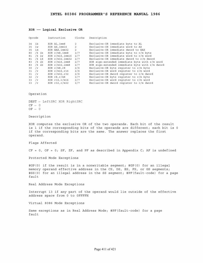
INTEL 80386 PROGRAMMER'S REFERENCE MANUAL 1986
Page 411 of 421
XOR ── Logical Exclusive OR
Opcode Instruction Clocks Description
34 ib XOR AL,imm8 2 Exclusive-OR immediate byte to AL35 iw XOR AX,imm16 2 Exclusive-OR immediate word to AX35 id XOR EAX,imm32 2 Exclusive-OR immediate dword to EAX80 /6 ib XOR r/m8,imm8 2/7 Exclusive-OR immediate byte to r/m byte81 /6 iw XOR r/m16,imm16 2/7 Exclusive-OR immediate word to r/m word81 /6 id XOR r/m32,imm32 2/7 Exclusive-OR immediate dword to r/m dword83 /6 ib XOR r/m16,imm8 2/7 XOR sign-extended immediate byte with r/m word83 /6 ib XOR r/m32,imm8 2/7 XOR sign-extended immediate byte with r/m dword30 /r XOR r/m8,r8 2/6 Exclusive-OR byte register to r/m byte31 /r XOR r/m16,r16 2/6 Exclusive-OR word register to r/m word31 /r XOR r/m32,r32 2/6 Exclusive-OR dword register to r/m dword32 /r XOR r8,r/m8 2/7 Exclusive-OR byte register to r/m byte33 /r XOR r16,r/m16 2/7 Exclusive-OR word register to r/m word33 /r XOR r32,r/m32 2/7 Exclusive-OR dword register to r/m dword
Operation
DEST ← LeftSRC XOR RightSRCCF ← 0OF ← 0
Description
XOR computes the exclusive OR of the two operands. Each bit of the resultis 1 if the corresponding bits of the operands are different; each bit is 0if the corresponding bits are the same. The answer replaces the firstoperand.
Flags Affected
CF = 0, OF = 0; SF, ZF, and PF as described in Appendix C; AF is undefined
Protected Mode Exceptions
#GP(0) if the result is in a nonwritable segment; #GP(0) for an illegalmemory operand effective address in the CS, DS, ES, FS, or GS segments;#SS(0) for an illegal address in the SS segment; #PF(fault-code) for a pagefault
Real Address Mode Exceptions
Interrupt 13 if any part of the operand would lie outside of the effectiveaddress space from 0 to 0FFFFH
Virtual 8086 Mode Exceptions
Same exceptions as in Real Address Mode; #PF(fault-code) for a pagefault
INTEL 80386 PROGRAMMER'S REFERENCE MANUAL 1986
Page 412 of 421
Appendix A Opcode Map
────────────────────────────────────────────────────────────────────────────
The opcode tables that follow aid in interpreting 80386 object code. Usethe high-order four bits of the opcode as an index to a row of the opcodetable; use the low-order four bits as an index to a column of the table. Ifthe opcode is 0FH, refer to the two-byte opcode table and use the secondbyte of the opcode to index the rows and columns of that table.
Key to Abbreviations
Operands are identified by a two-character code of the form Zz. The firstcharacter, an uppercase letter, specifies the addressing method; the secondcharacter, a lowercase letter, specifies the type of operand.
Codes for Addressing Method
A Direct address; the instruction has no modR/M byte; the address of the operand is encoded in the instruction; no base register, index register, or scaling factor can be applied; e.g., far JMP (EA).
C The reg field of the modR/M byte selects a control register; e.g., MOV (0F20, 0F22).
D The reg field of the modR/M byte selects a debug register; e.g., MOV (0F21,0F23).
E A modR/M byte follows the opcode and specifies the operand. The operand is either a general register or a memory address. If it is a memory address, the address is computed from a segment register and any of the following values: a base register, an index register, a scaling factor, a displacement.
F Flags Register.
G The reg field of the modR/M byte selects a general register; e.g., ADD (00).
I Immediate data. The value of the operand is encoded in subsequent bytes of the instruction.
J The instruction contains a relative offset to be added to the instruction pointer register; e.g., JMP short, LOOP.
M The modR/M byte may refer only to memory; e.g., BOUND, LES, LDS, LSS, LFS, LGS.
O The instruction has no modR/M byte; the offset of the operand is coded as a word or double word (depending on address size attribute) in the instruction. No base register, index register, or scaling factor can be applied; e.g., MOV (A0-A3).

INTEL 80386 PROGRAMMER'S REFERENCE MANUAL 1986
Page 413 of 421
R The mod field of the modR/M byte may refer only to a general register; e.g., MOV (0F20-0F24, 0F26).
S The reg field of the modR/M byte selects a segment register; e.g., MOV (8C,8E).
T The reg field of the modR/M byte selects a test register; e.g., MOV (0F24,0F26).
X Memory addressed by DS:SI; e.g., MOVS, COMPS, OUTS, LODS, SCAS.
Y Memory addressed by ES:DI; e.g., MOVS, CMPS, INS, STOS.
Codes for Operant Type
a Two one-word operands in memory or two double-word operands in memory, depending on operand size attribute (used only by BOUND).
b Byte (regardless of operand size attribute)
c Byte or word, depending on operand size attribute.
d Double word (regardless of operand size attribute)
p 32-bit or 48-bit pointer, depending on operand size attribute.
s Six-byte pseudo-descriptor
v Word or double word, depending on operand size attribute.
w Word (regardless of operand size attribute)
Register Codes
When an operand is a specific register encoded in the opcode, the registeris identified by its name; e.g., AX, CL, or ESI. The name of the registerindicates whether the register is 32-, 16-, or 8-bits wide. A registeridentifier of the form eXX is used when the width of the register depends onthe operand size attribute; for example, eAX indicates that the AX registeris used when the operand size attribute is 16 and the EAX register is usedwhen the operand size attribute is 32.

INTEL 80386 PROGRAMMER'S REFERENCE MANUAL 1986
Page 414 of 421
One-Byte Opcode Map
0 1 2 3 4 5 6 7 8 9 A B C D E F ╔═══════════════════════════════════════════════════════════╤════════╤════════╤═══════════════════════════════════════════════════════════╤════════╤════════╗ ║ ADD │ PUSH │ POP │ OR │ PUSH │ 2-byte ║0╟─────────┬─────────┬─────────┬─────────┬─────────┬─────────┤ │ ├─────────┬─────────┬─────────┬─────────┬─────────┬─────────┤ │ ║ ║ Eb,Gb │ Ev,Gv │ Gb,Eb │ Gv,Ev │ AL,Ib │ eAX,Iv │ ES │ ES │ Eb,Gb │ Ev,Gv │ Gb,Eb │ Gv,Ev │ AL,Ib │ eAX,Iv │ CS │ escape ║ ╠═════════╧═════════╧═════════╧═════════╧═════════╧═════════╪════════╪════════╪═════════╧═════════╧═════════╧═════════╧═════════╧═════════╪════════╪════════╣ ║ ADC │ PUSH │ POP │ SBB │ PUSH │ POP ║1╟─────────┬─────────┬─────────┬─────────┬─────────┬─────────┤ │ ├─────────┬─────────┬─────────┬─────────┬─────────┬─────────┤ │ ║ ║ Eb,Gb │ Ev,Gv │ Gb,Eb │ Gv,Ev │ AL,Ib │ eAX,Iv │ SS │ SS │ Eb,Gb │ Ev,Gv │ Gb,Eb │ Gv,Ev │ AL,Ib │ eAX,Iv │ DS │ DS ║ ╠═════════╧═════════╧═════════╧═════════╧═════════╧═════════╪════════╪════════╪═════════╧═════════╧═════════╧═════════╧═════════╧═════════╪════════╪════════╣ ║ AND │ SEG │ │ SUB │ SEG │ ║2╟─────────┬─────────┬─────────┬─────────┬─────────┬─────────┤ │ DAA ├─────────┬─────────┬─────────┬─────────┬─────────┬─────────┤ │ DAS ║ ║ Eb,Gb │ Ev,Gv │ Gb,Eb │ Gv,Ev │ AL,Ib │ eAX,Iv │ =ES │ │ Eb,Gb │ Ev,Gv │ Gb,Eb │ Gv,Ev │ AL,Ib │ eAX,Iv │ =CS │ ║ ╠═════════╧═════════╧═════════╧═════════╧═════════╧═════════╪════════╪════════╪═════════╧═════════╧═════════╧═════════╧═════════╧═════════╪════════╪════════╣ ║ XOR │ SEG │ │ CMP │ SEG │ ║3╟─────────┬─────────┬─────────┬─────────┬─────────┬─────────┤ │ AAA ├─────────┬─────────┬─────────┬─────────┬─────────┬─────────┤ │ AAS ║ ║ Eb,Gb │ Ev,Gv │ Gb,Eb │ Gv,Ev │ AL,Ib │ eAX,Iv │ =SS │ │ Eb,Gb │ Ev,Gv │ Gb,Eb │ Gv,Ev │ AL,Ib │ eAX,Iv │ =CS │ ║ ╠═════════╧═════════╧═════════╧═════════╧═════════╧═════════╧════════╧════════╪═════════╧═════════╧═════════╧═════════╧═════════╧═════════╧════════╧════════╣ ║ INC general register │ DEC general register ║4╟─────────┬─────────┬─────────┬─────────┬─────────┬─────────┬────────┬────────┼─────────┬─────────┬─────────┬─────────┬─────────┬─────────┬────────┬────────╢ ║ eAX │ eCX │ eDX │ eBX │ eSP │ eBP │ eSI │ eDI │ eAX │ eCX │ eDX │ eBX │ eSP │ eBP │ eSI │ eDI ║ ╠═════════╧═════════╧═════════╧═════════╧═════════╧═════════╧════════╧════════╪═════════╧═════════╧═════════╧═════════╧═════════╧═════════╧════════╧════════╣ ║ PUSH general register │ POP into general register ║5╟─────────┬─────────┬─────────┬─────────┬─────────┬─────────┬────────┬────────┼─────────┬─────────┬─────────┬─────────┬─────────┬─────────┬────────┬────────╢ ║ eAX │ eCX │ eDX │ eBX │ eSP │ eBP │ eSI │ eDI │ eAX │ eCX │ eDX │ eBX │ eSP │ eBP │ eSI │ eDI ║ ╠═════════╪═════════╪═════════╪═════════╪═════════╪═════════╪════════╪════════╪═════════╪═════════╪═════════╪═════════╪═════════╪═════════╪════════╪════════╣ ║ │ │ BOUND │ ARPL │ SEG │ SEG │ Operand│ Address│ PUSH │ IMUL │ PUSH │ IMUL │ INSB │ INSW/D │ OUTSB │OUTSW/D ║6║ PUSHA │ POPA │ │ │ │ │ │ │ │ │ │ │ │ │ │ ║ ║ │ │ Gv,Ma │ Ew,Rw │ =FS │ =GS │ Size │ Size │ Ib │ GvEvIv │ Ib │ GvEvIv │ Yb,DX │ Yb,DX │ Dx,Xb │ DX,Xv ║ ╠═════════╧═════════╧═════════╧═════════╧═════════╧═════════╧════════╧════════╪═════════╧═════════╧═════════╧═════════╧═════════╧═════════╧════════╧════════╣ ║ Short displacement jump of condition (Jb) │ Short-displacement jump on condition(Jb) ║7╟─────────┬─────────┬─────────┬─────────┬─────────┬─────────┬────────┬────────┼─────────┬─────────┬─────────┬─────────┬─────────┬─────────┬────────┬────────╢ ║ JO │ JNO │ JB │ JNB │ JZ │ JNZ │ JBE │ JNBE │ JS │ JNS │ JP │ JNP │ JL │ JNL │ JLE │ JNLE ║ ╠═════════╧═════════╪═════════╪═════════╪═════════╧═════════╪════════╧════════╪═════════╧═════════╧═════════╧═════════╪═════════╪═════════╪════════╪════════╣ ║ Immediate Grpl │ │ Grpl │ TEST │ XCNG │ MOV │ MOV │ LEA │ MOV │ POP ║8╟─────────┬─────────┤ │ ├─────────┬─────────┼────────┬────────┼─────────┬─────────┬─────────┬─────────┤ │ │ │ ║ ║ Eb,Ib │ Ev,Iv │ │ Ev,Iv │ Eb,Gb │ Ev,Gv │ Eb,Gb │ Ev,Gv │ Eb,Gb │ Ev,Gv │ Gb,Eb │ Gv,Ev │ Ew,Sw │ Gv,M │ Sw,Ew │ Ev ║ ╠═════════╪═════════╧═════════╧═════════╧═════════╧═════════╧════════╧════════╪═════════╪═════════╪═════════╪═════════╪═════════╪═════════╪════════╪════════╣ ║ │ XCHG word or double-word register with eAX │ │ │ CALL │ │ PUSHF │ POPF │ │ ║9║ NOP ├─────────┬─────────┬─────────┬─────────┬─────────┬────────┬────────┤ CBW │ CWD │ │ WAIT │ │ │ SAHF │ LAHF ║ ║ │ eCX │ eDX │ eBX │ eSP │ eBP │ eSI │ eDI │ │ │ Ap │ │ Fv │ Fv │ │ ║ ╠═════════╧═════════╧═════════╧═════════╪═════════╪═════════╪════════╪════════╪═════════╧═════════╪═════════╪═════════╪═════════╪═════════╪════════╪════════╣ ║ MOV │ MOVSB │ MOVSW/D │ CMPSB │CMPSW/D │ TEST │ STOSB │ STOSW/D │ LODSB │ LODSW/D │ SCASB │SCASW/D ║A╟─────────┬─────────┬─────────┬─────────┤ │ │ │ ├─────────┬─────────┤ │ │ │ │ │ ║ ║ AL,Ob │ eAX,Ov │ Ob,AL │ Ov,eAX │ Xb,Yb │ Xv,Yv │ Xb,Yb │ Xv,Yv │ AL,Ib │ eAX,Iv │ Yb,AL │ Yv,eAX │ AL,Xb │ eAX,Xv │ AL,Xb │eAX,Xv ║ ╠═════════╧═════════╧═════════╧═════════╧═════════╧═════════╧════════╧════════╪═════════╧═════════╧═════════╧═════════╧═════════╧═════════╧════════╧════════╣ ║ MOV immediate byte into byte register │ MOV immediate word or double into word or double register ║B╟─────────┬─────────┬─────────┬─────────┬─────────┬─────────┬────────┬────────┼─────────┬─────────┬─────────┬─────────┬─────────┬─────────┬────────┬────────╢ ║ AL │ CL │ DL │ BL │ AH │ CH │ DH │ BH │ eAX │ eCX │ eDX │ eBX │ eSP │ eBP │ eSI │ eDI ║ ╠═════════╧═════════╪═════════╧═════════╪═════════╪═════════╪════════╧════════╪═════════╪═════════╪═════════╧═════════╪═════════╪═════════╪════════╪════════╣ ║ Shift Grp2 │ RET near │ LES │ LDS │ MOV │ ENTER │ │ RET far │ INT │ INT │ │ ║C╟─────────┬─────────┼─────────┬─────────┤ │ ├────────┬────────┤ │ LEAVE ├─────────┬─────────┤ │ │ INTO │ IRET ║ ║ Eb,Ib │ Ev,Iv │ Iw │ │ Gv,Mp │ Gv,Mp │ Eb,Ib │ Ev,Iv │ Iw,Ib │ │ Iw │ │ 3 │ Ib │ │ ║ ╠═════════╧═════════╧═════════╧═════════╪═════════╪═════════╪════════╪════════╪═════════╧═════════╧═════════╧═════════╧═════════╧═════════╧════════╧════════╣ ║ Shift Grp2 │ │ │ │ │ ║D╟─────────┬─────────┬─────────┬─────────┤ AAM │ AAD │ │ XLAT │ ESC(Escape to coprocessor instruction set) ║ ║ Eb,1 │ Ev,1 │ Eb,CL │ Ev,CL │ │ │ │ │ ║ ╠═════════╪═════════╪═════════╪═════════╪═════════╧═════════╪════════╧════════╪═════════╤═════════════════════════════╤═══════════════════╤═════════════════╣ ║ LOOPNE │ LOOPE │ LOOP │ JCXZ │ IN │ OUT │ CALL │ JNP │ IN │ OUT ║E║ │ │ │ ├─────────┬─────────┼────────┬────────┤ ├─────────┬─────────┬─────────┼─────────┬─────────┼────────┬────────╢ ║ Jb │ Jb │ Jb │ Jb │ AL,Ib │ eAX,Ib │ Ib,AL │ Ib,eAX │ Av │ Jv │ Ap │ Jb │ AL,DX │ eAX,DX │ DX,AL │ DX,eAX ║ ╠═════════╪═════════╪═════════╪═════════╪═════════╪═════════╪════════╧════════╪═════════╪═════════╪═════════╪═════════╪═════════╪═════════╪════════╪════════╣ ║ │ │ │ REP │ │ │ Unary Grp3 │ │ │ │ │ │ │INC/DEC │Indirct ║F║ LOCK │ │ REPNE │ │ HLT │ CMC ├────────┬────────┤ CLC │ STC │ CLI │ STI │ CLD │ STD │ │ ║ ║ │ │ │ REPE │ │ │ Eb │ Ev │ │ │ │ │ │ │ Grp4 │ Grp5 ║ ╚═════════╧═════════╧═════════╧═════════╧═════════╧═════════╧════════╧════════╧═════════╧═════════╧═════════╧═════════╧═════════╧═════════╧════════╧════════╝
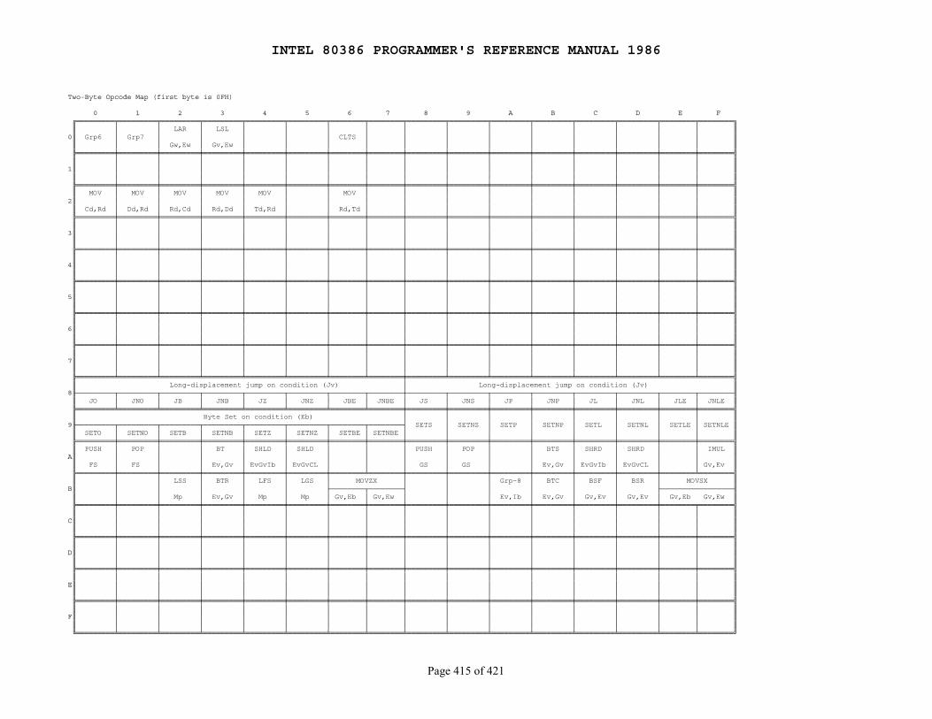
INTEL 80386 PROGRAMMER'S REFERENCE MANUAL 1986
Page 415 of 421
Two-Byte Opcode Map (first byte is 0FH)
0 1 2 3 4 5 6 7 8 9 A B C D E F ╔═════════╤═════════╤═════════╤═════════╤═════════╤═════════╤════════╤════════╤═════════╤═════════╤═════════╤═════════╤═════════╤═════════╤════════╤════════╗ ║ │ │ LAR │ LSL │ │ │ │ │ │ │ │ │ │ │ │ ║0║ Grp6 │ Grp7 │ │ │ │ │ CLTS │ │ │ │ │ │ │ │ │ ║ ║ │ │ Gw,Ew │ Gv,Ew │ │ │ │ │ │ │ │ │ │ │ │ ║ ╠═════════╪═════════╪═════════╪═════════╪═════════╪═════════╪════════╪════════╪═════════╪═════════╪═════════╪═════════╪═════════╪═════════╪════════╪════════╣ ║ │ │ │ │ │ │ │ │ │ │ │ │ │ │ │ ║1║ │ │ │ │ │ │ │ │ │ │ │ │ │ │ │ ║ ║ │ │ │ │ │ │ │ │ │ │ │ │ │ │ │ ║ ╠═════════╪═════════╪═════════╪═════════╪═════════╪═════════╪════════╪════════╪═════════╪═════════╪═════════╪═════════╪═════════╪═════════╪════════╪════════╣ ║ MOV │ MOV │ MOV │ MOV │ MOV │ │ MOV │ │ │ │ │ │ │ │ │ ║2║ │ │ │ │ │ │ │ │ │ │ │ │ │ │ │ ║ ║ Cd,Rd │ Dd,Rd │ Rd,Cd │ Rd,Dd │ Td,Rd │ │ Rd,Td │ │ │ │ │ │ │ │ │ ║ ╠═════════╪═════════╪═════════╪═════════╪═════════╪═════════╪════════╪════════╪═════════╪═════════╪═════════╪═════════╪═════════╪═════════╪════════╪════════╣ ║ │ │ │ │ │ │ │ │ │ │ │ │ │ │ │ ║3║ │ │ │ │ │ │ │ │ │ │ │ │ │ │ │ ║ ║ │ │ │ │ │ │ │ │ │ │ │ │ │ │ │ ║ ╠═════════╪═════════╪═════════╪═════════╪═════════╪═════════╪════════╪════════╪═════════╪═════════╪═════════╪═════════╪═════════╪═════════╪════════╪════════╣ ║ │ │ │ │ │ │ │ │ │ │ │ │ │ │ │ ║4║ │ │ │ │ │ │ │ │ │ │ │ │ │ │ │ ║ ║ │ │ │ │ │ │ │ │ │ │ │ │ │ │ │ ║ ╠═════════╪═════════╪═════════╪═════════╪═════════╪═════════╪════════╪════════╪═════════╪═════════╪═════════╪═════════╪═════════╪═════════╪════════╪════════╣ ║ │ │ │ │ │ │ │ │ │ │ │ │ │ │ │ ║5║ │ │ │ │ │ │ │ │ │ │ │ │ │ │ │ ║ ║ │ │ │ │ │ │ │ │ │ │ │ │ │ │ │ ║ ╠═════════╪═════════╪═════════╪═════════╪═════════╪═════════╪════════╪════════╪═════════╪═════════╪═════════╪═════════╪═════════╪═════════╪════════╪════════╣ ║ │ │ │ │ │ │ │ │ │ │ │ │ │ │ │ ║6║ │ │ │ │ │ │ │ │ │ │ │ │ │ │ │ ║ ║ │ │ │ │ │ │ │ │ │ │ │ │ │ │ │ ║ ╠═════════╪═════════╪═════════╪═════════╪═════════╪═════════╪════════╪════════╪═════════╪═════════╪═════════╪═════════╪═════════╪═════════╪════════╪════════╣ ║ │ │ │ │ │ │ │ │ │ │ │ │ │ │ │ ║7║ │ │ │ │ │ │ │ │ │ │ │ │ │ │ │ ║ ║ │ │ │ │ │ │ │ │ │ │ │ │ │ │ │ ║ ╠═════════╧═════════╧═════════╧═════════╧═════════╧═════════╧════════╧════════╪═════════╧═════════╧═════════╧═════════╧═════════╧═════════╧════════╧════════╣ ║ Long-displacement jump on condition (Jv) │ Long-displacement jump on condition (Jv) ║8╟─────────┬─────────┬─────────┬─────────┬─────────┬─────────┬────────┬────────┼─────────┬─────────┬─────────┬─────────┬─────────┬─────────┬────────┬────────╢ ║ JO │ JNO │ JB │ JNB │ JZ │ JNZ │ JBE │ JNBE │ JS │ JNS │ JP │ JNP │ JL │ JNL │ JLE │ JNLE ║ ╠═════════╧═════════╧═════════╧═════════╧═════════╧═════════╧════════╧════════╪═════════╪═════════╪═════════╪═════════╪═════════╪═════════╪════════╪════════╣ ║ Byte Set on condition (Eb) │ │ │ │ │ │ │ │ ║9╟─────────┬─────────┬─────────┬─────────┬─────────┬─────────┬────────┬────────┤ SETS │ SETNS │ SETP │ SETNP │ SETL │ SETNL │ SETLE │ SETNLE ║ ║ SETO │ SETNO │ SETB │ SETNB │ SETZ │ SETNZ │ SETBE │ SETNBE │ │ │ │ │ │ │ │ ║ ╠═════════╪═════════╪═════════╪═════════╪═════════╪═════════╪════════╪════════╪═════════╪═════════╪═════════╪═════════╪═════════╪═════════╪════════╪════════╣ ║ PUSH │ POP │ │ BT │ SHLD │ SHLD │ │ │ PUSH │ POP │ │ BTS │ SHRD │ SHRD │ │ IMUL ║A║ │ │ │ │ │ │ │ │ │ │ │ │ │ │ │ ║ ║ FS │ FS │ │ Ev,Gv │ EvGvIb │ EvGvCL │ │ │ GS │ GS │ │ Ev,Gv │ EvGvIb │ EvGvCL │ │ Gv,Ev ║ ╠═════════╪═════════╪═════════╪═════════╪═════════╪═════════╪════════╧════════╪═════════╪═════════╪═════════╪═════════╪═════════╪═════════╪════════╧════════╣ ║ │ │ LSS │ BTR │ LFS │ LGS │ MOVZX │ │ │ Grp-8 │ BTC │ BSF │ BSR │ MOVSX ║B║ │ │ │ │ │ ├────────┬────────┤ │ │ │ │ │ ├─────────────────╢ ║ │ │ Mp │ Ev,Gv │ Mp │ Mp │ Gv,Eb │ Gv,Ew │ │ │ Ev,Ib │ Ev,Gv │ Gv,Ev │ Gv,Ev │ Gv,Eb Gv,Ew ║ ╠═════════╪═════════╪═════════╪═════════╪═════════╪═════════╪════════╪════════╪═════════╪═════════╪═════════╪═════════╪═════════╪═════════╪════════╤════════╣ ║ │ │ │ │ │ │ │ │ │ │ │ │ │ │ │ ║C║ │ │ │ │ │ │ │ │ │ │ │ │ │ │ │ ║ ║ │ │ │ │ │ │ │ │ │ │ │ │ │ │ │ ║ ╠═════════╪═════════╪═════════╪═════════╪═════════╪═════════╪════════╪════════╪═════════╪═════════╪═════════╪═════════╪═════════╪═════════╪════════╪════════╣ ║ │ │ │ │ │ │ │ │ │ │ │ │ │ │ │ ║D║ │ │ │ │ │ │ │ │ │ │ │ │ │ │ │ ║ ║ │ │ │ │ │ │ │ │ │ │ │ │ │ │ │ ║ ╠═════════╪═════════╪═════════╪═════════╪═════════╪═════════╪════════╪════════╪═════════╪═════════╪═════════╪═════════╪═════════╪═════════╪════════╪════════╣ ║ │ │ │ │ │ │ │ │ │ │ │ │ │ │ │ ║E║ │ │ │ │ │ │ │ │ │ │ │ │ │ │ │ ║ ║ │ │ │ │ │ │ │ │ │ │ │ │ │ │ │ ║ ╠═════════╪═════════╪═════════╪═════════╪═════════╪═════════╪════════╪════════╪═════════╪═════════╪═════════╪═════════╪═════════╪═════════╪════════╪════════╣ ║ │ │ │ │ │ │ │ │ │ │ │ │ │ │ │ ║F║ │ │ │ │ │ │ │ │ │ │ │ │ │ │ │ ║ ║ │ │ │ │ │ │ │ │ │ │ │ │ │ │ │ ║ ╚═════════╧═════════╧═════════╧═════════╧═════════╧═════════╧════════╧════════╧═════════╧═════════╧═════════╧═════════╧═════════╧═════════╧════════╧════════╝
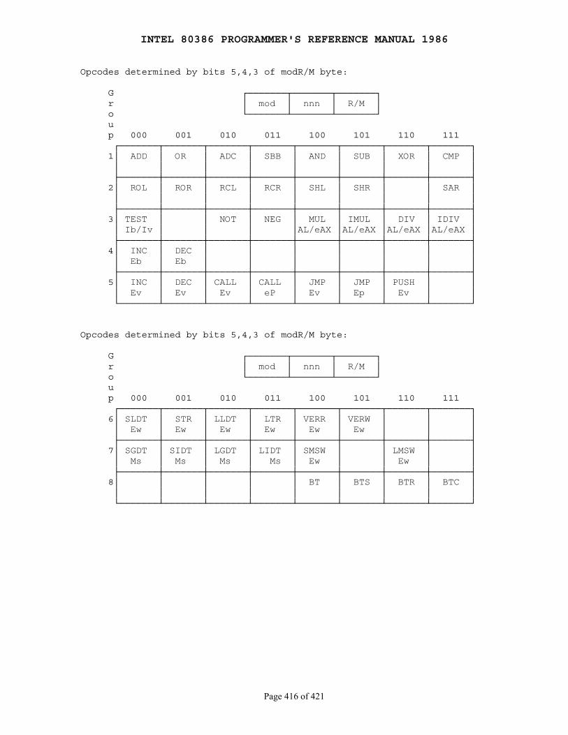
INTEL 80386 PROGRAMMER'S REFERENCE MANUAL 1986
Page 416 of 421
Opcodes determined by bits 5,4,3 of modR/M byte:
G ┌───────┬───────┬───────┐ r │ mod │ nnn │ R/M │ o └───────┴───────┴───────┘ u p 000 001 010 011 100 101 110 111 ┌───────┬───────┬───────┬───────┬───────┬───────┬───────┬───────┐ 1│ ADD │ OR │ ADC │ SBB │ AND │ SUB │ XOR │ CMP │ │ │ │ │ │ │ │ │ │ ├───────┼───────┼───────┼───────┼───────┼───────┼───────┼───────┤ 2│ ROL │ ROR │ RCL │ RCR │ SHL │ SHR │ │ SAR │ │ │ │ │ │ │ │ │ │ ├───────┼───────┼───────┼───────┼───────┼───────┼───────┼───────┤ 3│ TEST │ │ NOT │ NEG │ MUL │ IMUL │ DIV │ IDIV │ │ Ib/Iv │ │ │ │AL/eAX │AL/eAX │AL/eAX │AL/eAX │ ├───────┼───────┼───────┼───────┼───────┼───────┼───────┼───────┤ 4│ INC │ DEC │ │ │ │ │ │ │ │ Eb │ Eb │ │ │ │ │ │ │ ├───────┼───────┼───────┼───────┼───────┼───────┼───────┼───────┤ 5│ INC │ DEC │ CALL │ CALL │ JMP │ JMP │ PUSH │ │ │ Ev │ Ev │ Ev │ eP │ Ev │ Ep │ Ev │ │ └───────┴───────┴───────┴───────┴───────┴───────┴───────┴───────┘
Opcodes determined by bits 5,4,3 of modR/M byte:
G ┌───────┬───────┬───────┐ r │ mod │ nnn │ R/M │ o └───────┴───────┴───────┘ u p 000 001 010 011 100 101 110 111 ┌───────┬───────┬───────┬───────┬───────┬───────┬───────┬───────┐ 6│ SLDT │ STR │ LLDT │ LTR │ VERR │ VERW │ │ │ │ Ew │ Ew │ Ew │ Ew │ Ew │ Ew │ │ │ ├───────┼───────┼───────┼───────┼───────┼───────┼───────┼───────┤ 7│ SGDT │ SIDT │ LGDT │ LIDT │ SMSW │ │ LMSW │ │ │ Ms │ Ms │ Ms │ Ms │ Ew │ │ Ew │ │ ├───────┼───────┼───────┼───────┼───────┼───────┼───────┼───────┤ 8│ │ │ │ │ BT │ BTS │ BTR │ BTC │ │ │ │ │ │ │ │ │ │ └───────┴───────┴───────┴───────┴───────┴───────┴───────┴───────┘

INTEL 80386 PROGRAMMER'S REFERENCE MANUAL 1986
Page 417 of 421
Appendix B Complete Flag Cross-Reference
────────────────────────────────────────────────────────────────────────────
Key to Codes
T = instruction tests flag
M = instruction modifies flag (either sets or resets depending on operands)
0 = instruction resets flag
1 = instruction sets flag
── = instruction's effect on flag is undefined
R = instruction restores prior value of flag
blank = instruction does not affect flag
Instruction OF SF ZF AF PF CF TF IF DF NT RF
AAA ── ── ── TM ── MAAD ── M M ── M ──AAM ── M M ── M ──AAS ── ── ── TM ── MADC M M M M M TMADD M M M M M MAND 0 M M ── M 0ARPL MBOUNDBSF/BSR ── ── M ── ── ──BT/BTS/BTR/BTC ── ── ── ── ── MCALLCBWCLC 0CLD 0CLI 0CLTSCMC MCMP M M M M M MCMPS M M M M M M TCWDDAA ── M M TM M TMDAS ── M M TM M TMDEC M M M M MDIV ── ── ── ── ── ──ENTERESCHLTIDIV ── ── ── ── ── ──IMUL M ── ── ── ── MININC M M M M MINS TINT 0 0
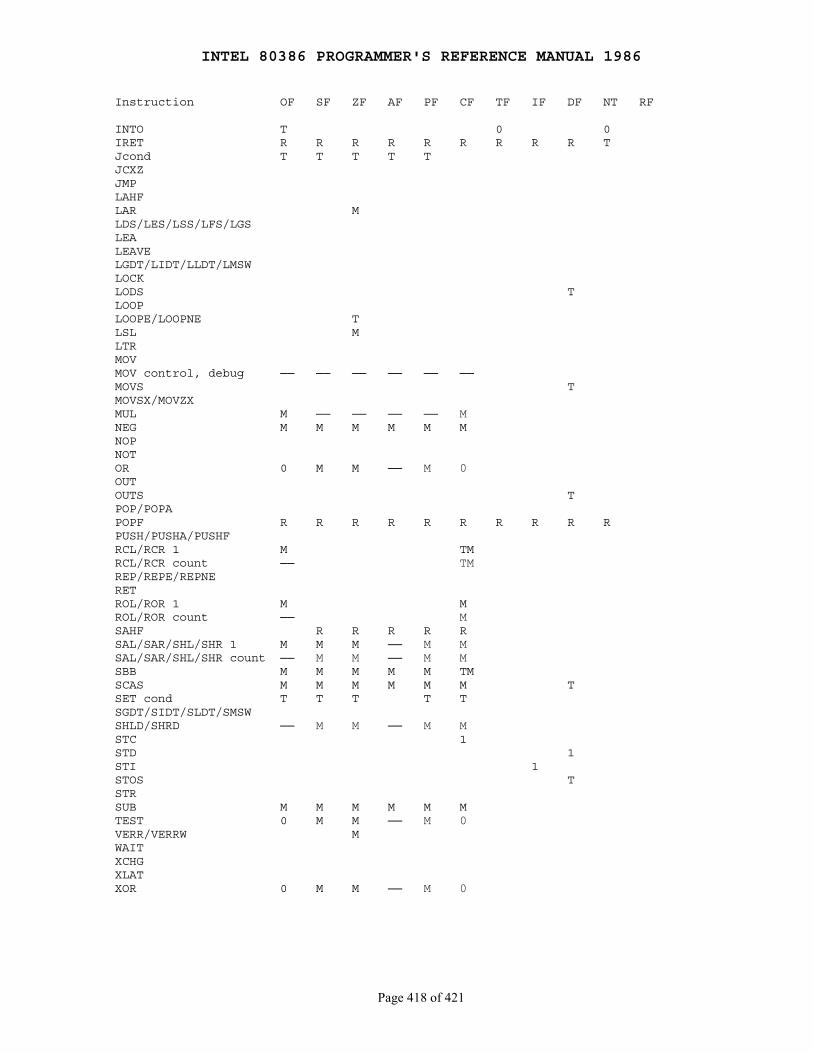
INTEL 80386 PROGRAMMER'S REFERENCE MANUAL 1986
Page 418 of 421
Instruction OF SF ZF AF PF CF TF IF DF NT RF
INTO T 0 0IRET R R R R R R R R R TJcond T T T T TJCXZJMPLAHFLAR MLDS/LES/LSS/LFS/LGSLEALEAVELGDT/LIDT/LLDT/LMSWLOCKLODS TLOOPLOOPE/LOOPNE TLSL MLTRMOVMOV control, debug ── ── ── ── ── ──MOVS TMOVSX/MOVZXMUL M ── ── ── ── MNEG M M M M M MNOPNOTOR 0 M M ── M 0OUTOUTS TPOP/POPAPOPF R R R R R R R R R RPUSH/PUSHA/PUSHFRCL/RCR 1 M TMRCL/RCR count ── TMREP/REPE/REPNERETROL/ROR 1 M MROL/ROR count ── MSAHF R R R R RSAL/SAR/SHL/SHR 1 M M M ── M MSAL/SAR/SHL/SHR count ── M M ── M MSBB M M M M M TMSCAS M M M M M M TSET cond T T T T TSGDT/SIDT/SLDT/SMSWSHLD/SHRD ── M M ── M MSTC 1STD 1STI 1STOS TSTRSUB M M M M M MTEST 0 M M ── M 0VERR/VERRW MWAITXCHGXLATXOR 0 M M ── M 0
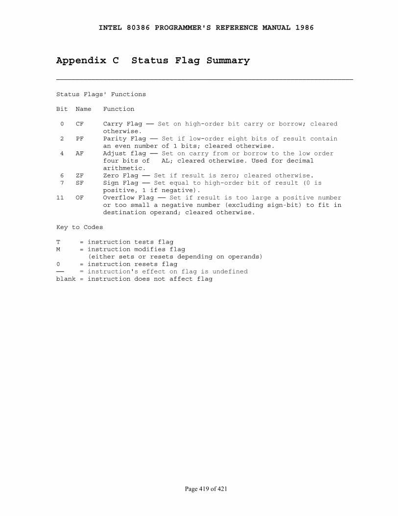
INTEL 80386 PROGRAMMER'S REFERENCE MANUAL 1986
Page 419 of 421
Appendix C Status Flag Summary
────────────────────────────────────────────────────────────────────────────
Status Flags' Functions
Bit Name Function
0 CF Carry Flag ── Set on high-order bit carry or borrow; cleared otherwise. 2 PF Parity Flag ── Set if low-order eight bits of result contain an even number of 1 bits; cleared otherwise. 4 AF Adjust flag ── Set on carry from or borrow to the low order four bits of AL; cleared otherwise. Used for decimal arithmetic. 6 ZF Zero Flag ── Set if result is zero; cleared otherwise. 7 SF Sign Flag ── Set equal to high-order bit of result (0 is positive, 1 if negative).11 OF Overflow Flag ── Set if result is too large a positive number or too small a negative number (excluding sign-bit) to fit in destination operand; cleared otherwise.
Key to Codes
T = instruction tests flagM = instruction modifies flag (either sets or resets depending on operands)0 = instruction resets flag── = instruction's effect on flag is undefinedblank = instruction does not affect flag
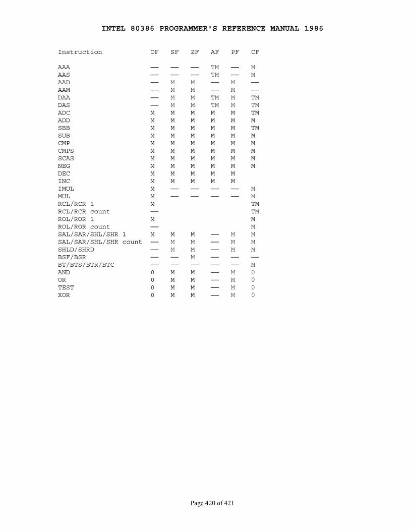
INTEL 80386 PROGRAMMER'S REFERENCE MANUAL 1986
Page 420 of 421
Instruction OF SF ZF AF PF CF
AAA ── ── ── TM ── MAAS ── ── ── TM ── MAAD ── M M ── M ──AAM ── M M ── M ──DAA ── M M TM M TMDAS ── M M TM M TMADC M M M M M TMADD M M M M M MSBB M M M M M TMSUB M M M M M MCMP M M M M M MCMPS M M M M M MSCAS M M M M M MNEG M M M M M MDEC M M M M MINC M M M M MIMUL M ── ── ── ── MMUL M ── ── ── ── MRCL/RCR 1 M TMRCL/RCR count ── TMROL/ROR 1 M MROL/ROR count ── MSAL/SAR/SHL/SHR 1 M M M ── M MSAL/SAR/SHL/SHR count ── M M ── M MSHLD/SHRD ── M M ── M MBSF/BSR ── ── M ── ── ──BT/BTS/BTR/BTC ── ── ── ── ── MAND 0 M M ── M 0OR 0 M M ── M 0TEST 0 M M ── M 0XOR 0 M M ── M 0
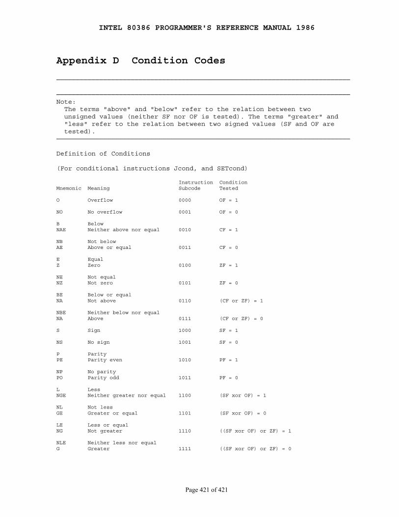
INTEL 80386 PROGRAMMER'S REFERENCE MANUAL 1986
Page 421 of 421
Appendix D Condition Codes
───────────────────────────────────────────────────────────────────────────
───────────────────────────────────────────────────────────────────────────Note: The terms "above" and "below" refer to the relation between two unsigned values (neither SF nor OF is tested). The terms "greater" and "less" refer to the relation between two signed values (SF and OF are tested).───────────────────────────────────────────────────────────────────────────
Definition of Conditions
(For conditional instructions Jcond, and SETcond)
Instruction ConditionMnemonic Meaning Subcode Tested
O Overflow 0000 OF = 1
NO No overflow 0001 OF = 0
B BelowNAE Neither above nor equal 0010 CF = 1
NB Not belowAE Above or equal 0011 CF = 0
E EqualZ Zero 0100 ZF = 1
NE Not equalNZ Not zero 0101 ZF = 0
BE Below or equalNA Not above 0110 (CF or ZF) = 1
NBE Neither below nor equalNA Above 0111 (CF or ZF) = 0
S Sign 1000 SF = 1
NS No sign 1001 SF = 0
P ParityPE Parity even 1010 PF = 1
NP No parityPO Parity odd 1011 PF = 0
L LessNGE Neither greater nor equal 1100 (SF xor OF) = 1
NL Not lessGE Greater or equal 1101 (SF xor OF) = 0
LE Less or equalNG Not greater 1110 ((SF xor OF) or ZF) = 1
NLE Neither less nor equalG Greater 1111 ((SF xor OF) or ZF) = 0