Embed Size (px)
Citation preview
32- bit Microprocessor-Intel 80386 30 Marks
Course Outcome:
Explain memory management and concept of pipelining.
Describe the concept of paging and addressing.

Signal Description of 80386
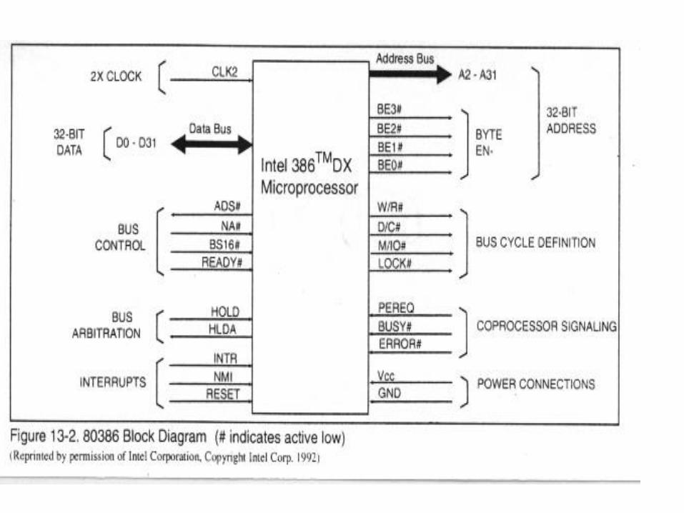
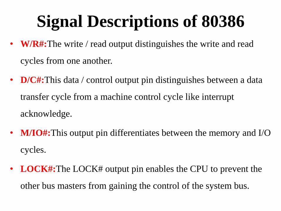
Signal Descriptions of 80386
• W/R#:The write / read output distinguishes the write and read
cycles from one another.
• D/C#:This data / control output pin distinguishes between a data
transfer cycle from a machine control cycle like interrupt
acknowledge.
• M/IO#:This output pin differentiates between the memory and I/O
cycles.
• LOCK#:The LOCK# output pin enables the CPU to prevent the
other bus masters from gaining the control of the system bus.
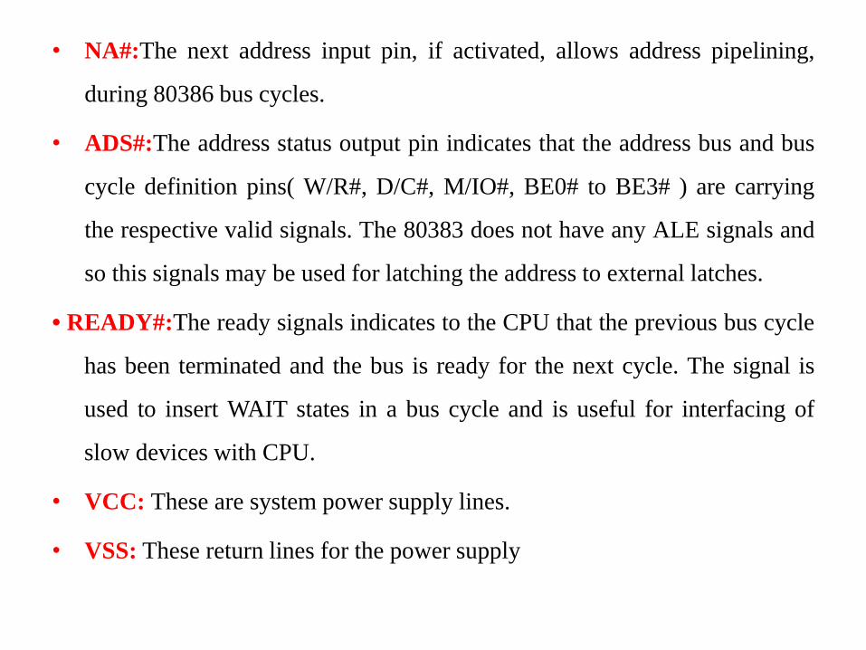
• NA#:The next address input pin, if activated, allows address pipelining,
during 80386 bus cycles.
• ADS#:The address status output pin indicates that the address bus and bus
cycle definition pins( W/R#, D/C#, M/IO#, BE0# to BE3# ) are carrying
the respective valid signals. The 80383 does not have any ALE signals and
so this signals may be used for latching the address to external latches.
• READY#:The ready signals indicates to the CPU that the previous bus cycle
has been terminated and the bus is ready for the next cycle. The signal is
used to insert WAIT states in a bus cycle and is useful for interfacing of
slow devices with CPU.
• VCC: These are system power supply lines.
• VSS: These return lines for the power supply
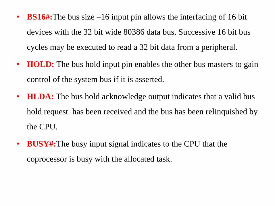
• BS16#:The bus size –16 input pin allows the interfacing of 16 bit
devices with the 32 bit wide 80386 data bus. Successive 16 bit bus
cycles may be executed to read a 32 bit data from a peripheral.
• HOLD: The bus hold input pin enables the other bus masters to gain
control of the system bus if it is asserted.
• HLDA: The bus hold acknowledge output indicates that a valid bus
hold request has been received and the bus has been relinquished by
the CPU.
• BUSY#:The busy input signal indicates to the CPU that the
coprocessor is busy with the allocated task.
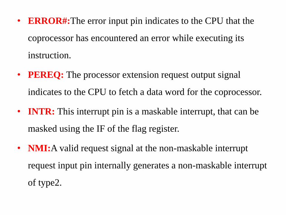
• ERROR#:The error input pin indicates to the CPU that the
coprocessor has encountered an error while executing its
instruction.
• PEREQ: The processor extension request output signal
indicates to the CPU to fetch a data word for the coprocessor.
• INTR: This interrupt pin is a maskable interrupt, that can be
masked using the IF of the flag register.
• NMI:A valid request signal at the non-maskable interrupt
request input pin internally generates a non-maskable interrupt
of type2.
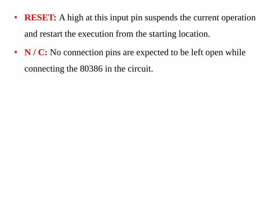
• RESET: A high at this input pin suspends the current operation
and restart the execution from the starting location.
• N / C: No connection pins are expected to be left open while
connecting the 80386 in the circuit.
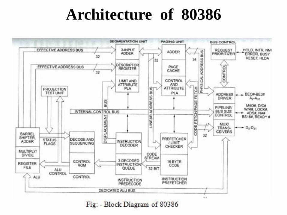
Architecture of 80386
Architecture of 80386
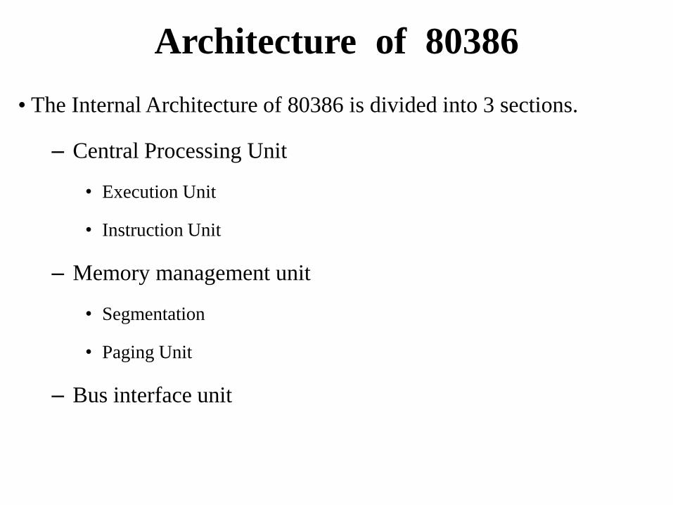
• The Internal Architecture of 80386 is divided into 3 sections.
– Central Processing Unit
• Execution Unit
• Instruction Unit
– Memory management unit
• Segmentation
• Paging Unit
– Bus interface unit
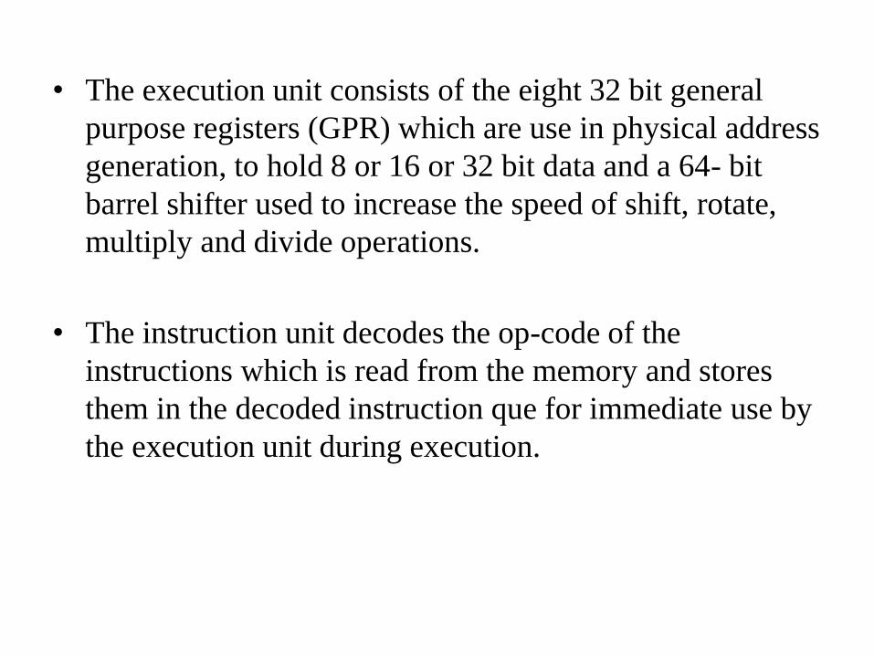
• The execution unit consists of the eight 32 bit general
purpose registers (GPR) which are use in physical address
generation, to hold 8 or 16 or 32 bit data and a 64- bit
barrel shifter used to increase the speed of shift, rotate,
multiply and divide operations.
• The instruction unit decodes the op-code of the
instructions which is read from the memory and stores
them in the decoded instruction que for immediate use by
the execution unit during execution.
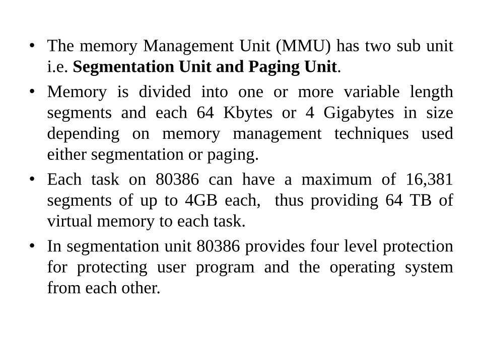
• The memory Management Unit (MMU) has two sub unit
i.e. Segmentation Unit and Paging Unit.
• Memory is divided into one or more variable length
segments and each 64 Kbytes or 4 Gigabytes in size
depending on memory management techniques used
either segmentation or paging.
• Each task on 80386 can have a maximum of 16,381
segments of up to 4GB each, thus providing 64 TB of
virtual memory to each task.
• In segmentation unit 80386 provides four level protection
for protecting user program and the operating system
from each other.
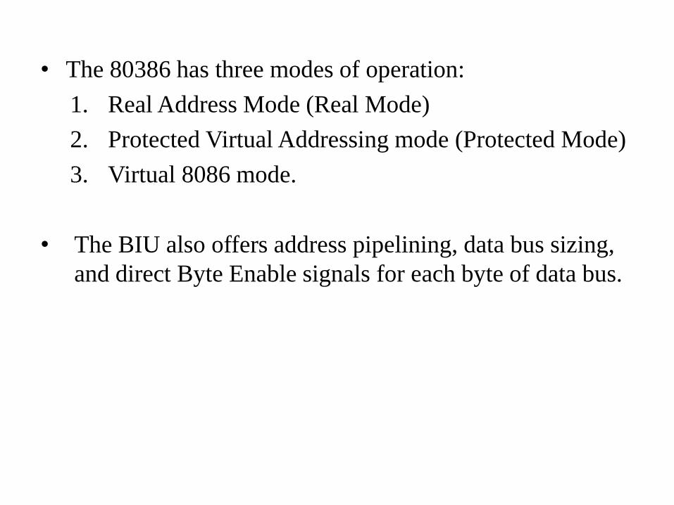
• The 80386 has three modes of operation:
1. Real Address Mode (Real Mode)
2. Protected Virtual Addressing mode (Protected Mode)
3. Virtual 8086 mode.
• The BIU also offers address pipelining, data bus sizing,
and direct Byte Enable signals for each byte of data bus.
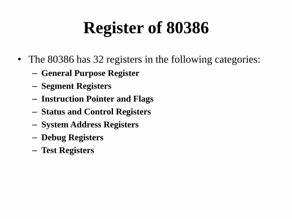
Register of 80386
• The 80386 has 32 registers in the following categories:
– General Purpose Register
– Segment Registers
– Instruction Pointer and Flags
– Status and Control Registers
– System Address Registers
– Debug Registers
– Test Registers


