Embed Size (px)
Citation preview

Integrated Diagnostic Software
User's Guide
Release 1.2
Dec. 15, 2008
http://www.obd2be.com/

Integrated Diagnostic Software (IDS)
i
Contents
1 INTRODUCTION................................................................................................................................ 1 Application Overview..................................................................................................................................... 1 Vehicle Diagnostic Connectors ..................................................................................................................... 1 Interface Devices .......................................................................................................................................... 1 System Navigation ........................................................................................................................................ 1
2 SYSTEM SET UP AND INFORMATION ................................................................................. 2
User Preferences .............................................................................................................................. 2 System Information ....................................................................................................................................... 3 System Utilities.............................................................................................................................................. 4
3 VEHICLE ID AND SESSION MANAGEMENT ...................................................................... 5 Identifying a new vehicle ............................................................................................................................... 5 Manual Vehicle Entry .................................................................................................................................... 6 Vehicle Specification Screen......................................................................................................................... 7 Closing a Session ......................................................................................................................................... 8 Restoring a Vehicle Session ......................................................................................................................... 9 Log Viewer .................................................................................................................................................. 10 4 TOOLBOX........................................................................................................................................ 11 5 GLOSSARY OF SYMBOLS ............................................................................................................ 12
http://www.obd2be.com/

Integrated Diagnostic Software (IDS)
1
1 Introduction
Application Overview Integrated Diagnostic Software (IDS) is the next generation diagnostic tool. IDS integrates WDS software modified to run on an off-the-shelf laptop with the Vehicle Communication Module (VCM) currently used in NGS+ and PDS, and a new Vehicle Measurement Module (VMM).
Vehicle Diagnostic Connectors The VCM 16-pin DLC cable is used to connect the VCM to the vehicle. The VCM and VMM connect to the laptop through the Ethernet-USB Adapter Cable (H406/H416).
Interface Devices The interface devices that are used with this application are: • VCM – Vehicle Communication Module – This device provides all link based functionality
including: Datalogger, Selftest, Service Functions, Module Configuration and Programming, etc. • VMM – Vehicle Measurement Module – This device provides the following functionality:
Oscilloscope, Digital Multi-Meter, Ignition System Test, Fuel System Test, and SGM. Note that the application will detect the interface device that is connected to the laptop. Indicator icons will appear at the bottom right-hand corner of the IDS screen when the VCM and/or VMM are connected.
System Navigation
When the application is first started, there will be three top tabs available in the upper left corner of the screen. These tabs are:
• System Page • Vehicle ID • Toolbox
Use a mouse, touch pad, or touch screen to navigate through the IDS tool. The touch screen functionality is dependant upon the specific laptop you are using. Selecting either the System Page or Vehicle ID tab will enable three sub-tabs at the lower left corner of the screen. There are no sub-tabs for the Toolbox. Navigating between screens is accomplished by clicking the blue tick button in the bottom right corner of the screen. Typically you will need to highlight a selection on the screen and then click the blue tick. Highlighting a selection can be done by a single mouse click or by touching the icon on your touch screen laptop.
Some screens allow you to return to the previous screen by selecting the back button from the right side of the screen. Certain screens and tests can be exited by selecting the menu button from the upper right corner of the screen. Hotspots are used throughout this application. These hotspots are acronyms that are highlighted in blue text. A single left mouse click on a hotspot will provide a definition at the bottom of the screen.
http://www.obd2be.com/
Integrated Diagnostic Software (IDS)
2
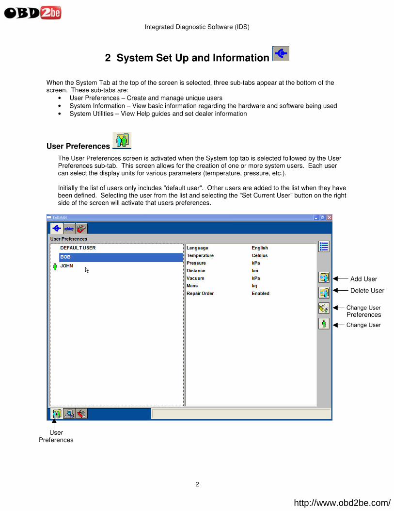
2 System Set Up and Information When the System Tab at the top of the screen is selected, three sub-tabs appear at the bottom of the screen. These sub-tabs are:
• User Preferences – Create and manage unique users • System Information – View basic information regarding the hardware and software being used • System Utilities – View Help guides and set dealer information
User Preferences The User Preferences screen is activated when the System top tab is selected followed by the User Preferences sub-tab. This screen allows for the creation of one or more system users. Each user can select the display units for various parameters (temperature, pressure, etc.). Initially the list of users only includes "default user". Other users are added to the list when they have been defined. Selecting the user from the list and selecting the "Set Current User" button on the right side of the screen will activate that users preferences.
User Preferences
Add User
Delete User
Change User Preferences
Change User
http://www.obd2be.com/

Integrated Diagnostic Software (IDS)
3
System Information Information related to the hardware and software in use can be viewed by selecting the System top tab followed by the System Information sub-tab. Information provided includes: System time and date, Dealer Information and Software Information.
System Information.ico
System Information
http://www.obd2be.com/

Integrated Diagnostic Software (IDS)
4
System Utilities The System Utilities screen is activated when the System top tab is selected followed by the System Utilities sub-tab. This screen allows the user to:
• Set dealer information to be included with each transaction • View the User Guide • View the Release Note that is issued with each software release • Access other utilities
System Utilities
http://www.obd2be.com/
Integrated Diagnostic Software (IDS)
5
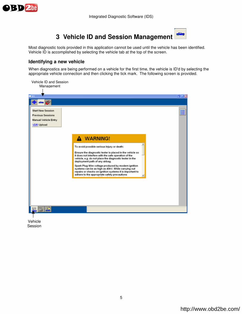
3 Vehicle ID and Session Management Most diagnostic tools provided in this application cannot be used until the vehicle has been identified. Vehicle ID is accomplished by selecting the vehicle tab at the top of the screen. Identifying a new vehicle When diagnostics are being performed on a vehicle for the first time, the vehicle is ID'd by selecting the appropriate vehicle connection and then clicking the tick mark. The following screen is provided.
Vehicle ID and Session Management
Vehicle Session
http://www.obd2be.com/
Integrated Diagnostic Software (IDS)
6
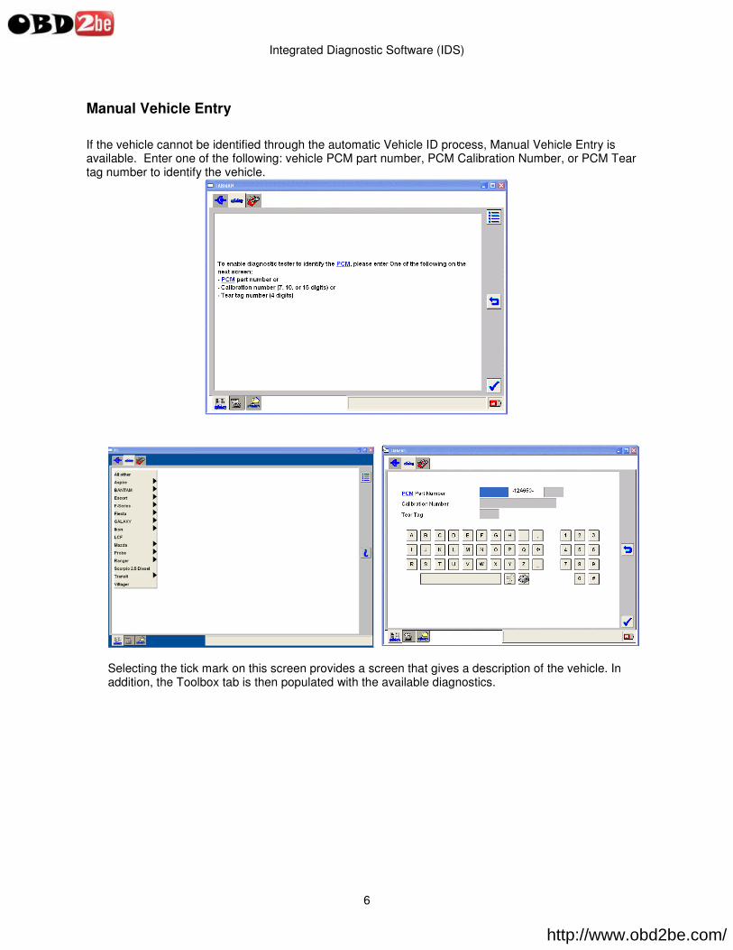
Manual Vehicle Entry If the vehicle cannot be identified through the automatic Vehicle ID process, Manual Vehicle Entry is available. Enter one of the following: vehicle PCM part number, PCM Calibration Number, or PCM Tear tag number to identify the vehicle.
Selecting the tick mark on this screen provides a screen that gives a description of the vehicle. In addition, the Toolbox tab is then populated with the available diagnostics.
http://www.obd2be.com/

Integrated Diagnostic Software (IDS)
7
Vehicle Specification Screen
Vehicle Specifications
http://www.obd2be.com/
Integrated Diagnostic Software (IDS)
8
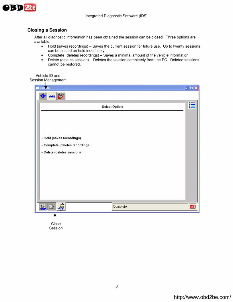
Closing a Session After all diagnostic information has been obtained the session can be closed. Three options are available:
• Hold (saves recordings) – Saves the current session for future use. Up to twenty sessions can be placed on hold indefinitely.
• Complete (deletes recordings) – Saves a minimal amount of the vehicle information • Delete (deletes session) – Deletes the session completely from the PC. Deleted sessions
cannot be restored.
Vehicle ID and Session Management
Close Session
http://www.obd2be.com/

Integrated Diagnostic Software (IDS)
9
Restoring a Vehicle Session
To return to a vehicle session that was previously marked as 'Hold' or 'Complete', select the Vehicle ID and Session Management tab at the top of the screen and then select "Previous Session". Sessions recently completed or previously placed in "Hold" will be listed. "Held" sessions will include any data recorded during the session. "Complete" sessions will include vehicle information, but not recordings. A session can be re-activated by selecting the session and then selecting the tick mark. Other tools are also provided for managing the saved sessions.
• The "Select Multiple Sessions" button allows the user to select more than one session to be deleted.
• The "Erase Selected Sessions" button deletes all highlighted sessions • The "Sort Sessions" button allows sessions to be sorted by VIN, Vehicle, Repair Order
number and/or date.
Select multiple sessions
Erase selected sessions
Sort sessions
Go back one screen
http://www.obd2be.com/
Integrated Diagnostic Software (IDS)
10
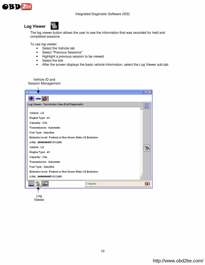
Log Viewer The log viewer button allows the user to see the information that was recorded for held and completed sessions. To use log viewer:
• Select the Vehicle tab • Select "Previous Sessions" • Highlight a previous session to be viewed • Select the tick • After the screen displays the basic vehicle information, select the Log Viewer sub-tab
Vehicle ID and Session Management
Log Viewer
http://www.obd2be.com/

Integrated Diagnostic Software (IDS)
11
4 Toolbox After the vehicle has been identified the toolbox tab becomes available. The tools provided are:
• Digital Multimeter – Provides various multimeter functions, such as measurements of AC voltage, Vehicle Battery voltage, DC voltage, Resistance, Frequency, Period, Duty Cycle, and Pressure (Requires the Vehicle Measurement Module - VMM)
• Oscilloscope - Provides a four-channel oscilloscope tool that can be utilized by the users to monitor electrical signals, to assist in diagnosis or analysis (Requires the VMM)
• Selftest – KOEO, KOER, and specialty tests based on system selected. • The Fuel Tool allows the user to perform the following tests:
o Key On Engine Off (KOEO) Fuel Pressure Leak-Down Test o Key Off Engine Running (KOER) Fuel Pressure Test o Key On Engine Off (KOEO) Relative Injector Flow Test
• Datalogger - A diagnostic application that allows the user to select and monitor parameters (PIDs) through the vehicle communication network from the J1962 connector
• Module Programming – Used to reprogram modules • Network Test – performs a test of the vehicle communication network • VDR – Vehicle Data Recorder allows vehicle data link recording for later playback • SGM – Signal Generator Monitor uses the Vehicle Measurement Module • Body, Chassis, Electrical or Powertrain – used to access tools specific to these systems
NOTE: Any test can be exited by selecting the menu button on the right side of the screen.
Toolbox.ico
Toolbox
http://www.obd2be.com/

Integrated Diagnostic Software (IDS)
12
5 Glossary of Symbols
System Tab: Set up the system and view information related to the system.
o User Preferences sub-tab: Add and remove users and set preferences
�� Add user: Add a new user �� Delete user: Remove a user
�� Change Preferences: Change user preferences
�� Set user: Set the current user
o System Information sub-tab: Display system information o System Utilities sub-tab: Set up the system and display user information
Vehicle ID tab: Identify a vehicle
o Vehicle Session sub-tab: Identify a vehicle or view the list of previous sessions o Log Viewer sub-tab: View recorded information
�� Configure Log Viewer button: Change the view in the Log Viewer
o Close Session sub-tab: Close vehicle session o When Previous Sessions has been selected:
�� Multiple Sessions Selector button: Select previous vehicle sessions �� Erase Session button: Erase selected previous vehicle sessions �� Sort Sessions button: Sort selected previous vehicle sessions
Toolbox tab: Lists available diagnostic tools
Module Configuration and Programming tab: Appears when a module is being programmed Tick icon: Accept a statement or screen Cancel icon: Cancel or close a statement or screen Menu icon: Print screen or exit a tool Information icon: View information related to the current screen Lock icon: Appears when a operation is being performed that cannot be interrupted Back button: Go to the previous screen
Toolbox.ico
System Information.ico
Information.ico
MultiSelect.ico
�����������������
���������
�������������
�������������������
���������������������
http://www.obd2be.com/

Integrated Diagnostic Software (IDS)
13
The following controls are available in Parameter Select:
Select System Options – button displays a menu that allows selection of Log Data, Print, Capture Setup and Exit functions.
Information icon gives the full name and a brief description of the highlighted parameter.
Save Parameter button archives the currently selected parameters to a group that can be retrieved.
Load Parameter icon retrieves the users saved parameter sets.
Clear icon clears all the currently selected parameters.
Continue button (tick mark) ends the parameter selection and takes the user to the Live Data Display screen. The lower left area of the Parameter Select screen and the Live Data Display screen provide navigation tabs to the main windows of Datalogger. They are as follows from left to right.
System Select tab provides the selection of system and modules.
Parameter Selection tab provides the selection of parameters available for the current module or subsystem.
Live Data Display tab displays vehicle data for all currently selected parameters.
Playback Display tab displays previously captured parameter data for analysis.
http://www.obd2be.com/

Integrated Diagnostic Software (IDS)
14
The following controls are available in Live Data Display :
Select System Options displays a menu, which allows selection to Log Data, Print, Capture Setup and Exit.
Data Capture starts a capture of data which, when selected, can be viewed in the Playback Display tab.
OSC Mode expands an on/off a step up and a step down control for parameters that the module enables for control. Controllable parameters are denoted by "#" next to their name.
Recording control displays a menu, which allows the user to set the time duration of data, captures and how much of the duration will be pre or post of the trigger.
Plot format, Limits and Range displays a menu, which allows the user to change the display format for the currently highlighted parameter to Digital, XY, Histogram or Bar graph. The screen display for the current parameter is also adjustable. This menu also allows configuration of "auto" triggers, which will initiate a capture or a beep if the user set limit value is reached. Two trigger types are available and are explained in the menus information "i" button.
Move changes the order of parameters When a parameter is highlighted and this button selected, then a second parameter is highlighted and the first parameter will be placed above the second.
Information button gives the full name and a brief description of the highlighted parameter.
Expand Signal View increases the height of XY parameters. When a signal has been expanded a complementary Contract Signal View control will appears, which will reduce the height.
Clear clears all on-screen plot lines of XY parameters.
Indicates that a VMM is required to perform this function.
http://www.obd2be.com/

IDS User's Guide
Trademark Acknowledgements Ford is a registered trademark of Ford Motor Company.
Copyright Information IDS User's Guide©2008 Ford Motor Company All rights reserved The information, specifications and illustrations in this manual are based on the latest information available at the time of printing. Ford Motor Company reserves the right to make changes at any time without notice.
http://www.obd2be.com/