Embed Size (px)
Citation preview

A n i n f o r m a t i o n s e r i e s f r o m t h e n a t i o n a l a u t h o r i t y o n c o n c r e t e m a s o n r y t e c h n o l o g y
NCMA TEK 6-11A 1
INSULATING CONCRETE MASONRY WALLS
INTRODUCTION
The variety of concrete masonry wall constructions provides for a number of insulating strategies, including: interior insulation, insulated cavities, insulation inserts, foamed-in-place insulation, granular fills in block core spaces, and exterior insulation systems. Each masonry wall design has different advantages and limitations with regard to each of these insulation strategies. The choice of insulation will depend on the desired thermal properties, climate conditions, ease of construction, cost, and other design criteria.
Note that insulation position within the wall can impact dew point location, and hence affect the condensation potential. See TEK 6-17A, Condensation Control in Concrete Masonry Walls (ref. 1) for more detailed information. Similarly, some insulations can act as an air barrier when installed continuously and with sealed joints. See TEK 6-14, Control of Infiltration in Concrete Masonry Walls, (ref. 2) for further information.
MASONRY THERMAL PERFORMANCE The thermal performance of a masonry wall depends on
its steady-state thermal characteristics (described by R-value or U-factor) as well as the thermal mass (heat capacity) char-acteristics of the wall. The steady state and mass performance are influenced by the size and type of masonry unit, type and location of insulation, finish materials, and density of masonry. Lower density concrete masonry mix designs result in higher R-values (i.e., lower U-factors) than higher density concretes.
Thermal mass describes the ability of materials to store heat. Because of its comparatively high density and specific heat, masonry provides very effective thermal storage. Masonry walls remain warm or cool long after the heat or air-conditioning has shut off. This, in turn, effectively reduces heating and cooling loads, moderates indoor temperature swings, and shifts heat-ing and cooling loads to off-peak hours. Due to the significant benefits of concrete masonry's inherent thermal mass, concrete masonry buildings can provide similar performance to more heavily insulated frame buildings.
Related TEK:6-1B, 6-2B, 6-13, 6-14, 6-17A,
Keywords: basement walls, energy conservation, insulation, multi-wythe walls, R-values, thermal insulation, thermal properties, thermal mass
The benefits of thermal mass have been incorporated into energy code requirements as well as sophisticated computer models. Energy codes and standards such as the International Energy Conservation Code (IECC) (ref. 5) and Energy Efficient Standard for Buildings Except Low-Rise Residential Build-ings, ASHRAE/IESNA Standard 90.1 (ref. 6), permit concrete masonry walls to have less insulation than frame wall systems to meet the energy requirements.
Although the thermal mass and inherent R-value/U-factor of concrete masonry may be enough to meet energy code re-quirements (particularly in warmer climates), concrete masonry walls often require additional insulation. When they do, there are many options available for insulating concrete masonry construction. When required, concrete masonry can provide walls with R-values that exceed code minimums (see refs. 3, 4). For overall project economy, however, the industry suggests a parametric analysis to determine reasonable insulation levels for the building envelope elements.
The effectiveness of thermal mass varies with factors such as climate, building design and insulation position. The effects of insulation position are discussed in the following sections. Note, however, that depending on the specific code compliance method chosen, insulation position may not be reflected in a particular code or standard.
There are several methods available to comply with the energy requirements of the IECC. One of the options, the IECC prescriptive R-values (IECC Table 502.2(1)) calls for "continuous insulation" on concrete masonry and other mass walls. This refers to insulation uninterrupted by furring or by the webs of concrete masonry units. Examples include rigid insulation adhered to the interior of the wall with furring and drywall applied over the insulation, continuous insulation in a masonry cavity wall, and exterior insulation and finish sys-tems. If the concrete masonry wall will not include continuous insulation, there are several other options to comply with the IECC requirements—concrete masonry walls are not required to have continuous insulation in order to meet the IECC. See
TEK 6-11AEnergy & IAQ (2010)

2 NCMA TEK 6-11A
TEK 6-12C, International Energy Conservation Code and Concrete Masonry and TEK 6-4A, Energy Code Compliance Using COMcheck (refs. 7, 8).
INTERIOR INSULATION Interior insulation refers to insulation applied to the interior
side of the concrete masonry, as shown in Figure 1. The insula-tion may be rigid board (extruded or expanded polystyrene or polyisocyanurate), closed-cell spray polyurethane foam, cel-lular glass, fibrous batt, or fibrous blown-in insulation (note, however, that fibrous insulation is susceptible to moisture). The interior wall surface is usually finished with gypsum wallboard or paneling.
Interior insulation allows for exposed masonry on the exterior, but isolates the masonry from the building's interior and so may reduce the effects of thermal mass.
With rigid board insulation, an adhesive is used to tempo-rarily hold the insulation in place while mechanical fasteners and a protective finish are applied. Furring may be used and held away from the face of the masonry with spacers. The space created by the spacers provides moisture protection, as well as a convenient and economical location for additional insulation, wiring or pipes.
As an alternative, wood or metal furring can be installed with insulation placed between the furring. The furring size is determined by the type of insulation and R-value required. Because the furring penetrates the insulation, the furring properties must be considered in analyzing the wall's thermal performance. Steel penetrations through insulation significantly affect the thermal resistance by conducting heat from one side of the insulation to the other. Although not as conductive as metal, the thermal resistance of wood and the cross-sectional area of the wood furring penetration should be taken into account
when determining overall R-values. See TEK 6-13A, Thermal Bridges in Wall Construction (ref. 9) for more information.
Closed cell spray polyurethane foam is typically installed between interior furring. The foam is applied as a liquid and ex-pands in-place. Proper training helps ensure a quality installation. The foam is resistant to both air and water vapor transmission.
When using interior insulation, concrete masonry can accommodate both vertical and horizontal reinforcement with partial or full grouting without interrupting the insulation layer.
The durability, weather resistance, and impact resistance of the exterior of a wall remain unchanged with the addition of interior insulation. Impact resistance on the interior surface is determined by the interior finish.
INTEGRAL INSULATION
Figure 2 illustrates some typical integral insulations in single-wythe masonry walls. Integral insulation refers to insulation placed between two layers of thermal mass. Ex-amples include insulation placed in concrete masonry cores and continuous insulation in a masonry cavity wall (note that an insulated masonry cavity wall can also be considered as exterior insulation if the thermal mass effect of the veneer is disregarded).
With integral insulation, some of the thermal mass (ma-sonry) is directly in contact with the indoor air, which provides excellent thermal mass benefits, while allowing exposed ma-sonry on both the exterior and interior.
Multi-wythe cavity walls contain insulation between two wythes of masonry. The continuous cavity insulation minimizes thermal bridging. The cavity width can be varied to achieve a
Figure 1—Examples of Interior Insulation
Continuous rigid insulation, metal furring (for electri-cal rough-in), and gypsum wallboard
Continuous poly-isocyanurate, heavy duty (HD) (joints taped or butt caulked) attached directly to masonry
Metal furring, insulation between furring and gypsum wallboard
Figure 2— Integral Insulation Examples
Concrete masonry backup, continuous insulation, minimum 1 in. (25 mm) cavity, and masonry veneer
Foamed-in-place or loose fill insulation
Molded polystyrene inserts
NCMA TEK 6-11A 3
wide range of R-values. Cavity insulation can be rigid board, closed cell spray polyurethane foam, or loose fill. To further increase the thermal performance, the cores of the backup wythe may be insulated.
When rigid board insulation is used in the cavity, the inner masonry wythe is typically completed first. The insulation is precut or scored by the manufacturer to facilitate placement between the wall ties. The board insulation may be attached with an adhesive or mechanical fasteners. Tight joints between the insulation boards maximize the thermal performance and reduce air leakage. In some cases, the joints between boards are set into an expandable bead of sealant, or caulked or taped to act as an air barrier.
Integral insulations placed in masonry cores are typically molded polystyrene inserts, foams, or expanded perlite or vermiculite granular fills. As for the furring used for interior insulation, the thermal resistance of the concrete masonry webs and any grouted cores should be accounted for when determining the thermal performance of the wall (see TEK 6-2B, ref. 3, for tabulated R-values of walls with core insulation). When using core insulation, the insulation should occupy all ungrouted core spaces (although some rigid inserts are configured to accom-modate reinforcing steel and grout in the same cell).
Foamed-in-place insulation is installed in masonry cores after the wall is completed. The installer either fills the cores from the top of the wall or pumps the foam through small holes drilled into the masonry. Foams may be sensitive to temperature, mixing conditions, or other factors. Therefore, manufacturers' instructions should be carefully followed to avoid excessive shrinkage due to improper mixing or placing of the foam.
Polystyrene inserts may be placed in the cores of conven-tional masonry units or used in specially designed units. Inserts are available in many shapes and sizes to provide a range of R-values and accommodate various construction conditions. In pre-insulated masonry, the inserts are installed by the manufacturer. Inserts are also available which are installed at the construction site.
Specially designed concrete masonry units may incorporate reduced-height webs to accommodate inserts in the cores. Such webs also reduce thermal bridging through masonry, since the reduced web area provides a smaller cross-sectional area for heat flow through a wall. To further reduce thermal bridging, some manufacturers have developed concrete masonry units with two cross webs rather than three.
Vertical and horizontal reinforcement grouted into the con-crete masonry cores may be required for structural performance. Cores to be grouted are isolated from cores to be insulated by placing mortar on the webs to confine the grout. Granular or foam insulation is placed in the ungrouted cores within the wall. Thermal resistance is then determined based on the average R-value of the wall area (see TEK 6-2B, ref. 3, for an explanation and example calculation). Some rigid inserts are configured to accommodate reinforcing steel and grout, to provide both thermal protection and structural performance. When inserts are used in grouted construction, the code-required minimum grout space dimensions must be met (see TEK 3-2A, ref. 10).
Granular fills are placed in masonry cores as the wall is laid up. Usually, the fills are poured directly from bags into the cores. A small amount of settlement usually occurs, but has a
relatively small effect on overall performance. Granular fills tend to flow out of any holes in the wall system. Therefore, weep holes should have noncorrosive screens on the interior or wicks to contain the fill while allowing water drainage. Bee holes or other gaps in the mortar joints should be filled. In addition, drilled-in anchors placed after the insulation require special installation procedures to prevent loss of the granular fill.
EXTERIOR INSULATION
Exterior insulated masonry walls are walls that have insu-lation on the exterior side of the thermal mass. In these walls, continuous exterior insulation envelopes the masonry, minimiz-ing the effect of thermal bridges. This places the thermal mass inside the insulation layer. Exterior insulation keeps masonry directly in contact with the interior conditioned air, providing the most thermal mass benefit of the three insulation strategies.
Exterior insulation also reduces heat loss and moisture movement due to air leakage when joints between the insula-tion boards are sealed. Exterior insulation negates the aesthetic advantage of exposed masonry. In addition, the insulation requires a protective finish to maintain the durability, integrity, and effectiveness of the insulation.
For exterior stucco installation, a reinforcing mesh is applied to reinforce the finish coating, improving the crack and impact resistance. Fiberglass mesh, corrosion-resistant woven wire mesh or metal lath is used for this purpose. After the mesh is installed, mechanical fasteners are placed through the insulation, to anchor securely into the concrete masonry. Mechanical fasteners can be either metal or nylon, although nylon limits the heat loss through the fasteners.
After the insulation and reinforcing mesh are mechanically fastened to the masonry, a finish coating is troweled onto the surface. This surface gives the wall its final color and texture, as well as providing weather and impact resistance.
BELOW GRADE APPLICATIONS
Below grade masonry walls typically use single-wythe wall construction, which can accommodate interior, integral, or exterior insulation.
Exterior or integral insulation is effective in moderating interior temperatures and in shifting peak energy loads. The typical furring used for interior insulation provides a place to run electric and plumbing lines, as well as being convenient for installing drywall or other interior finishes.
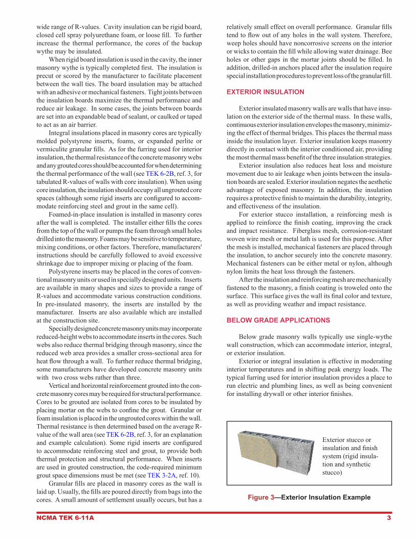
Figure 3—Exterior Insulation Example
Exterior stucco or insulation and finish system (rigid insula-tion and synthetic stucco)

4 NCMA TEK 6-11A
When using exterior or integral insulation strategies, ar-chitectural concrete masonry units provide a finished surface on the interior. Using smooth molded units at the wall base facilitates screeding the slab. After casting the slab, a molding strip, also serving as an electric raceway, can be placed against the smooth first course. The remainder of the wall may be
constructed of smooth, split-face, split ribbed, ground faced, scored or other architectural concrete masonry units.
Insulation on the exterior of below grade portions of the wall is temporarily held in place by adhesives until the backfill is placed. That portion of the rigid board which extends above grade should be mechanically attached and protected.
REFERENCES1. Condensation Control in Concrete Masonry Walls, TEK 6-17A. National Concrete Masonry Association, 2000.2. Control of Infiltration in Concrete Masonry Walls, TEK 6-14. National Concrete Masonry Association, 1986.3. R-Values and U-Factors of Single Wythe Concrete Masonry Walls, TEK 6-2B. National Concrete Masonry Association, 2009.4. R-Values of Multi-Wythe Concrete Masonry Walls, TEK 6-1B. National Concrete Masonry Association, 2009.5. International Energy Conservation Code. International Code Council, 2003, 2006 and 2009.6. Energy Efficient Standard for Buildings Except Low-Rise Residential Buildings, ASHRAE/IESNA Standard 90.1. American
Society of Heating, Refrigerating and Air Conditioning Engineers and Illuminating Engineers Society, 2001, 2004 and 2007.7. International Energy Conservation Code and Concrete Masonry, TEK 6-12C. National Concrete Masonry Association, 2007.8. Energy Code Compliance Using COMcheck TEK 6-4A. National Concrete Masonry Association, 2007.9. Thermal Bridges in Wall Construction, TEK 6-13A. National Concrete Masonry Association, 1996.10. Grouting Concrete Masonry Walls, TEK 3-2A. National Concrete Masonry Association, 2005.
NCMA and the companies disseminating this technical information disclaim any and all responsibility and liability for the accuracy and the application of the information contained in this publication.
NATIONAL CONCRETE MASONRY ASSOCIATION13750 Sunrise Valley Drive, Herndon, Virginia 20171
www.ncma.org
To order a complete TEK Manual or TEK Index, contact NCMA Publications (703) 713-1900