Embed Size (px)
Citation preview

Instructor: Dr. Istadi (http://tekim.undip.ac.id/staf/istadi ) Email: [email protected]
Course Syllabus: (Part 1) 1. Definitions of Natural Gas, Gas Reservoir, Gas Drilling
and Gas production (Pengertian gas alam, gas reservoir, gas drilling, dan produksi gas)
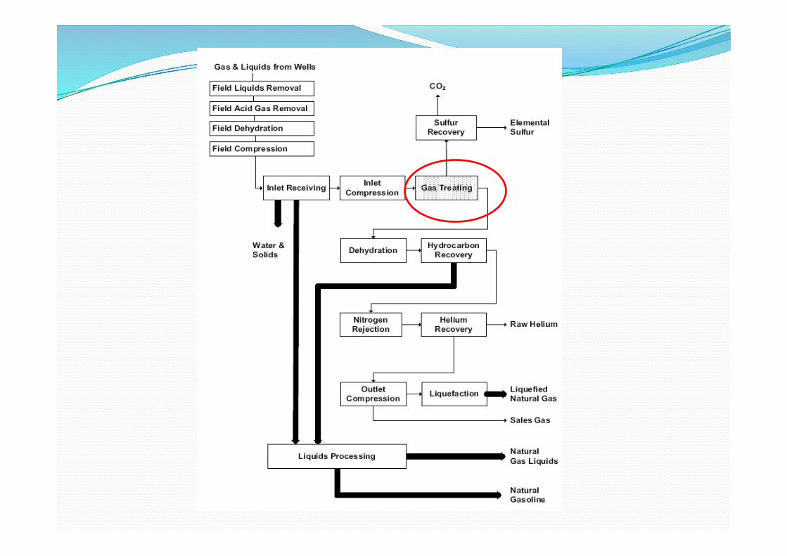
2. Overview of Gas Plant Processing (Overview Sistem Pemrosesan Gas) and Gas Field Operations and Inlet Receiving (Operasi Lapangan Gas dan Penerimaan Inlet)
3. Gas Treating: Chemical Treatments (Pengolahan Gas: secara kimia) and Sour Gas Treating (Pengolahan Gas Asam)
4. Gas Treating: Physical Treatments (Pengolahan Gas: secara fisika)
5. Gas Dehydration (Dehidrasi Gas) 6. Gas Dehydration (Dehidrasi Gas) 7. Hydrocarbons Recovery (Pengambilan Hidrokarbon)

DEFINISI ! Acid gas: gas alam yang mengandung H2S, dan CO2 ! Sour gas: gas alam yang mengandung H2S dan senyawa sulfur lainnya
(COS, CS2, dan mercaptan) ! Sweet gas: gas alam yang mengandung CO2 ! Gas treating: reduction of the “acid gases” to sufficiently low levels
to meet contractual specifications or permit additional processing in the plant without corrosion and plugging problems.
! Questions: ! Why are the acid gases a problem? ! What are the acid gas concentrations in natural gas? ! How much purification is needed? ! What is done with the acid gases after separation from the natural
gas? ! What processes are available for acid gas removal?
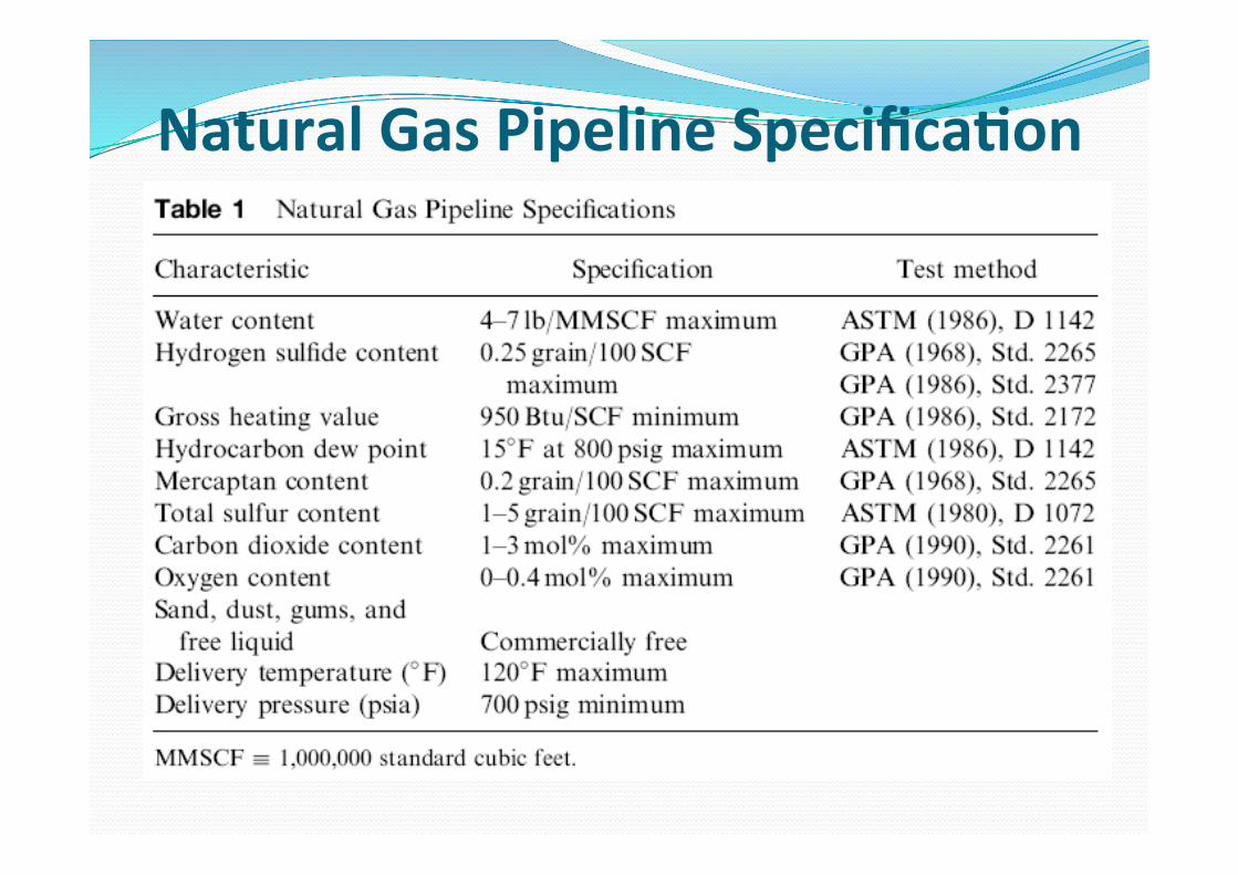
Natural Gas Pipeline Specifica>on

Acid Gas Defini>ons ! Hydrogen Sulfida (H2S):
! Hydrogen sulfide is highly toxic, and in the presence of water it forms a weak corrosive acid.
! threshold limit value (TLV): 10 ppmv ! When H2S concentrations are well above the ppmv level, other sulfur species can be present: carbon disulfide (CS2), mercaptans (RSH), and sulfides (RSR), in addition to elemental sulfur.
! If CO2 is present, the gas may contain trace amounts of carbonyl sulfide (COS).
! ASTM D4084 Standard test method for analysis of hydrogen sulfide in gaseous fuels
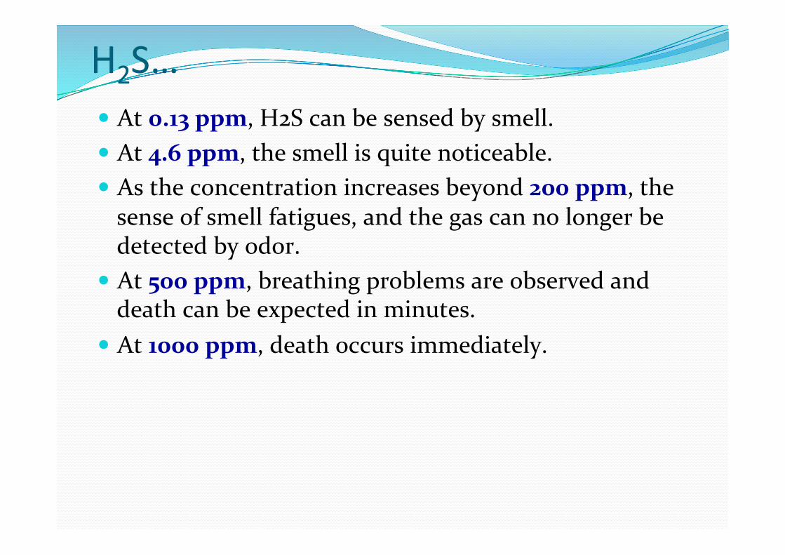
H2S… ! At 0.13 ppm, H2S can be sensed by smell. ! At 4.6 ppm, the smell is quite noticeable. ! As the concentration increases beyond 200 ppm, the sense of smell fatigues, and the gas can no longer be detected by odor.
! At 500 ppm, breathing problems are observed and death can be expected in minutes.
! At 1000 ppm, death occurs immediately.
Acid Gas Defini>ons
! Carbon dioxida (CO2): ! Carbon dioxide is nonflammable and, consequently, large quantities are undesirable in a fuel.
! it forms a weak, corrosive acid in the presence of water. ! If the partial pressure of CO2 exceeds 15 psia, inhibitors usually can only be used to prevent corrosion.
! The partial pressure of CO2 depends on the mole fraction of CO2 in the gas and the natural gas pressure.
! Corrosion rates will also depend on temperature. ! Threshold Limit Value (TLV): of a chemical substance is a level to which it is believed a worker can be exposed day after day for a working lifetime without adverse health effects.
Gas Purifica>on Level ! The inlet conditions at a gas processing plant are generally temperatures near ambient and pressures in the range of 300 to 1,000 psi (20 to 70 bar), so the partial pressures of the entering acid gases can be quite high
! If the gas is to be purified to a level suitable for transportation in a pipeline and used as a residential or industrial fuel, then the H2S concentration must be reduced to 0.25 g/100 SCF (6 mg/m3)
! the CO2 concentration must be reduced to a maximum of 3 to 4 mol%
! However, if the gas is to be processed for NGL recovery or nitrogen rejection in a cryogenic turboexpander process, CO2 may have to be removed to prevent formation of solids.
! If the gas is being fed to an LNG liquefaction facility, then the maximum CO2 level is about 50 ppmv

Acid Gas Disposal ! What becomes of the CO2 and H2S after their separation from the natural gas? ! The answer depends to a large extent on the quantity of the acid gases. ! Warning: CO2 is the most greenhouse gas contributor
! For CO2, if the quantities are large ! sometimes used as an injection fluid in EOR (enhanced oil recovery) projects.
In the case of H2S, four disposal op>ons are available:
! Incineration and venting, if environmental regulations regarding sulfur dioxide emissions can be satisfied
! Reaction with H2S scavengers, such as iron sponge ! Conversion to elemental sulfur by use of the Claus or similar process (2 H2S + O2 → S2 + 2 H2O)
! Disposal by injection into a suitable underground formation, ! if concentration is too high
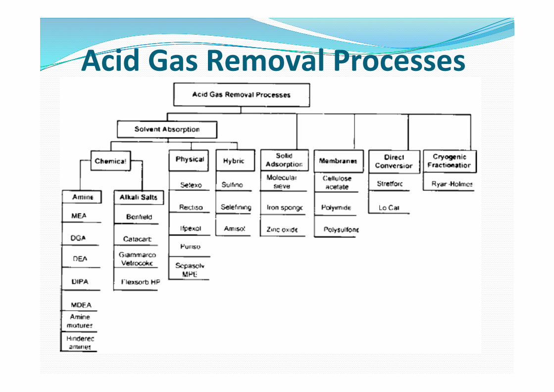
Acid Gas Removal Processes
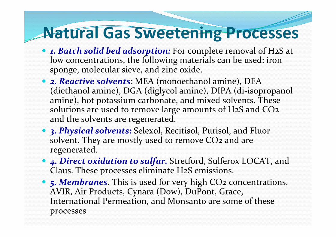
Natural Gas Sweetening Processes ! 1. Batch solid bed adsorption: For complete removal of H2S at low concentrations, the following materials can be used: iron sponge, molecular sieve, and zinc oxide.
! 2. Reactive solvents: MEA (monoethanol amine), DEA (diethanol amine), DGA (diglycol amine), DIPA (di-‐isopropanol amine), hot potassium carbonate, and mixed solvents. These solutions are used to remove large amounts of H2S and CO2 and the solvents are regenerated.
! 3. Physical solvents: Selexol, Recitisol, Purisol, and Fluor solvent. They are mostly used to remove CO2 and are regenerated.
! 4. Direct oxidation to sulfur. Stretford, Sulferox LOCAT, and Claus. These processes eliminate H2S emissions.
! 5. Membranes. This is used for very high CO2 concentrations. AVIR, Air Products, Cynara (Dow), DuPont, Grace, International Permeation, and Monsanto are some of these processes
Process Selec>on? Please consider: ! The type and concentration of impurities and hydrocarbon
composition of the sour gas. ! The temperature and pressure at which the sour gas is available. ! The specifications of the outlet gas (low outlet specifications favor the
amines). ! The volume or flow rate of gas to be processed. ! The specifications for the residue gas, the acid gas, and liquid products. ! The selectivity required for the acid gas removal. ! Feasibility of sulfur recovery ! The capital, operating, and royalty costs for the process. ! Acid gas selectivity required ! Presence of heavy aromatic in the gas ! Well location ! Relative economics ! The environmental constraints, including air pollution regulations
and disposal of byproducts considered hazardous chemicals.

PURIFICATION PROCESS ! Four scenarios are possible for acid gas removal from natural gas: ! CO2 removal from a gas that contains no H2S ! H2S removal from a gas that contains no CO2 ! Simultaneous removal of both CO2 and H2S ! Selective removal of H2S from a gas that contains both CO2 and H2S

Process selec>on chart for CO2 removal with no H2S present
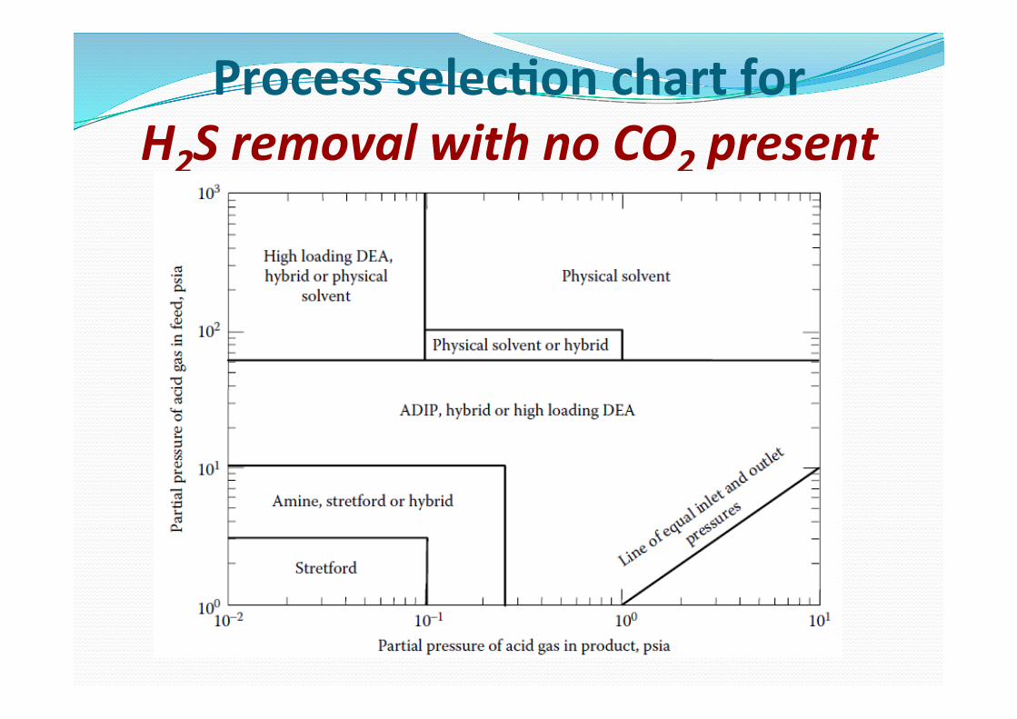
Process selec>on chart for H2S removal with no CO2 present
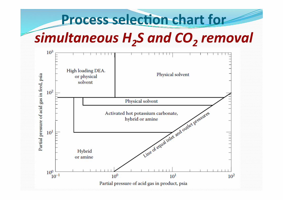
Process selec>on chart for simultaneous H2S and CO2 removal

Process selec>on chart for selec8ve H2S removal with CO2 present
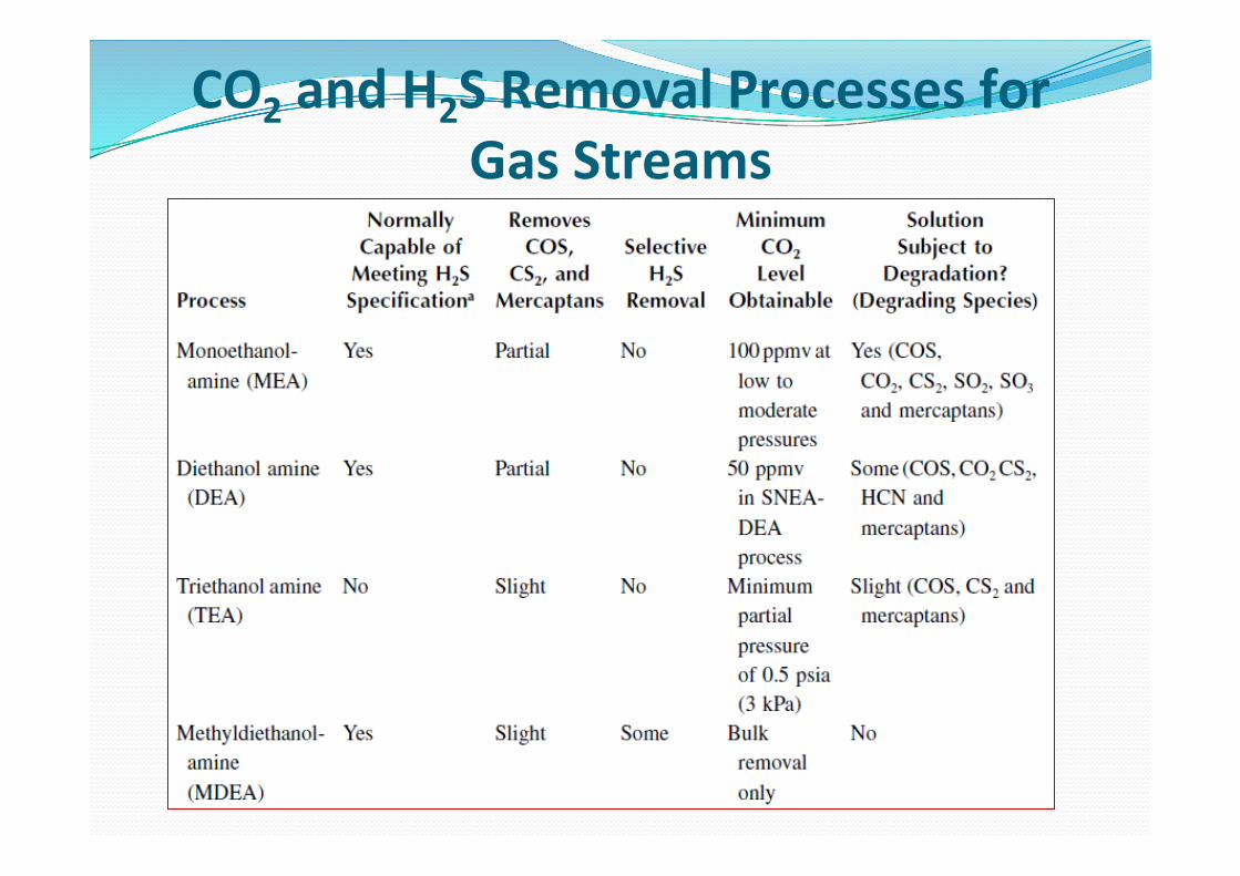
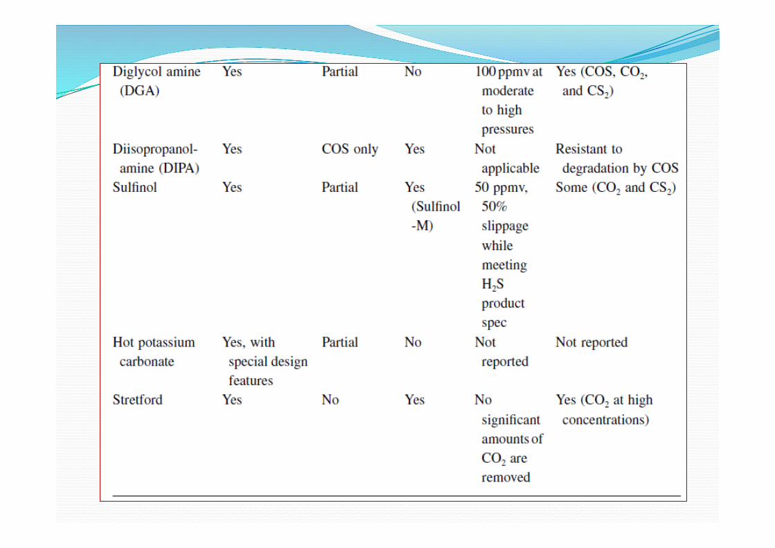
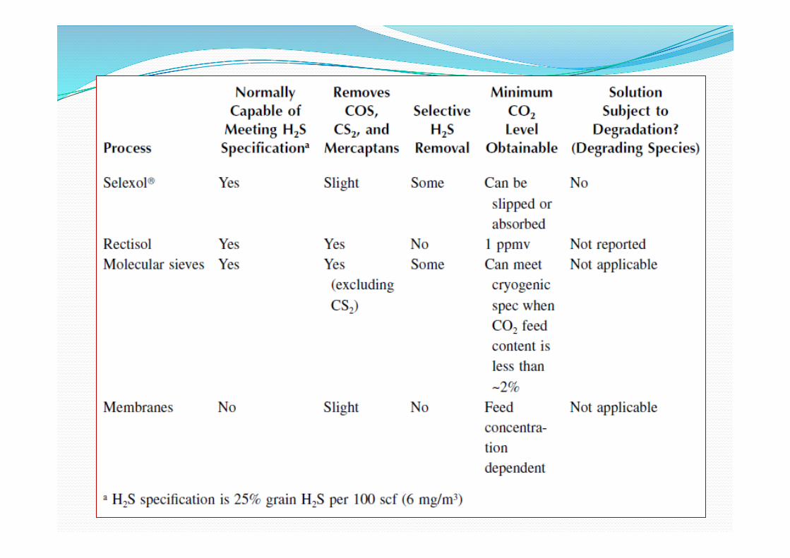
CO2 and H2S Removal Processes for Gas Streams
SOLVENT ABSORPTION PROCESSES ! In solvent absorption, the two major cost factors are: ! the solvent circulation rate, which affects both equipment size and operating costs,
! and the energy requirement for regenerating the solvent

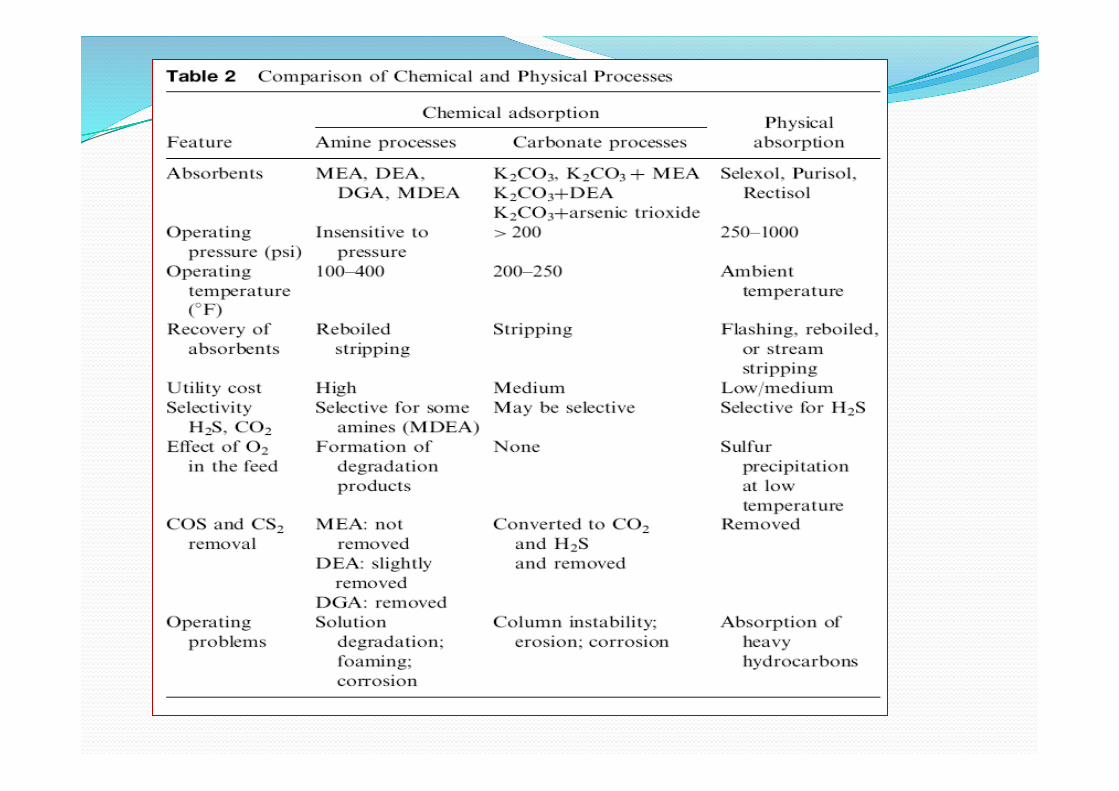
Comparison of Chemical and Physical Solvents
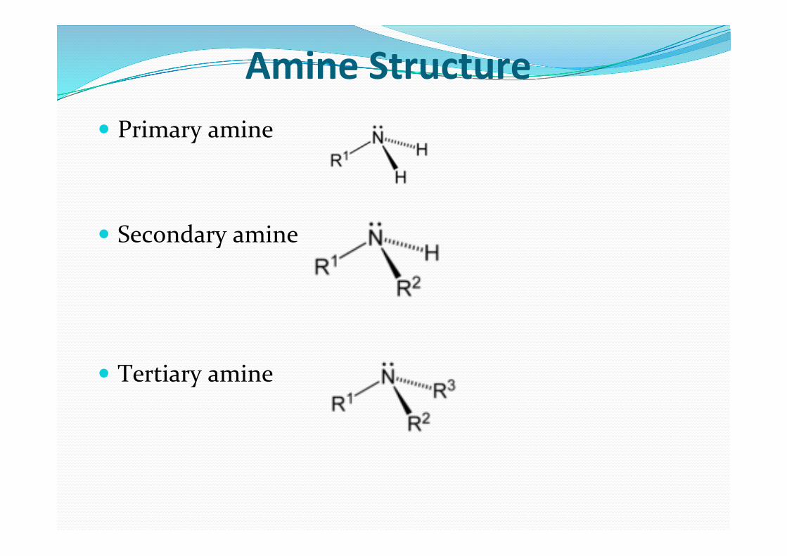
Amine Structure ! Primary amine
! Secondary amine
! Tertiary amine
amines… ! The amines are used in water solutions in concentrations ranging from approximately 10 to 65 wt% amines
! All commonly used amines are alkanolamines, which are amines with OH groups attached to the hydrocarbon groups to reduce their volatility
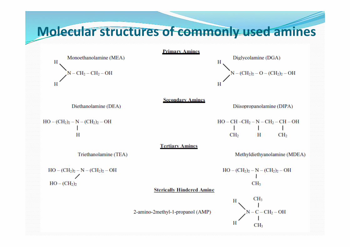
Molecular structures of commonly used amines
Amines remove H2S and CO2 in a two step process
! The gas dissolves in the liquid (physical absorption).
! The dissolved gas, which is a weak acid, reacts with the weakly basic amines.
! Absorption from the gas phase is governed by the partial pressure of the H2S and CO2 in the gas, whereas the reactions in the liquid phase are controlled by the reactivity of the dissolved species
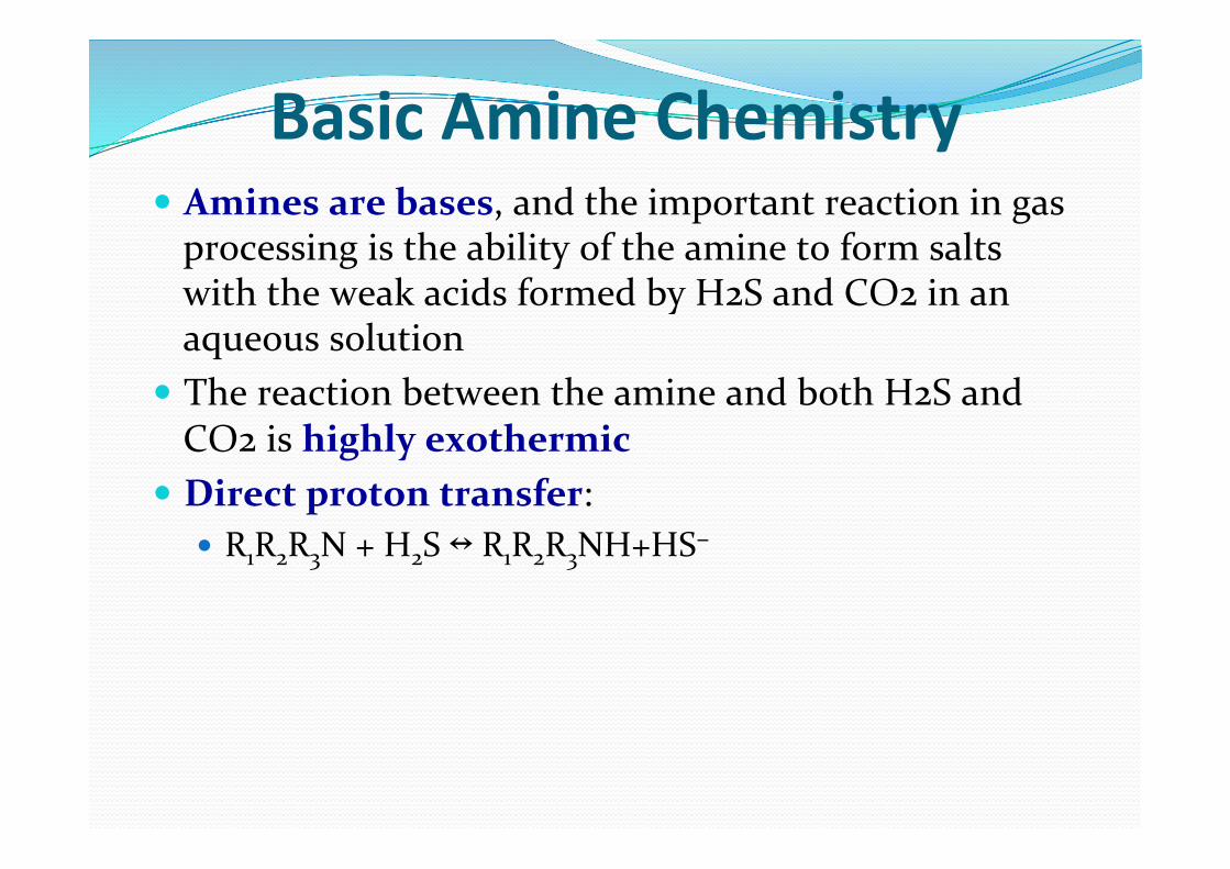
Basic Amine Chemistry ! Amines are bases, and the important reaction in gas processing is the ability of the amine to form salts with the weak acids formed by H2S and CO2 in an aqueous solution
! The reaction between the amine and both H2S and CO2 is highly exothermic
! Direct proton transfer: ! R1R2R3N + H2S ↔ R1R2R3NH+HS−
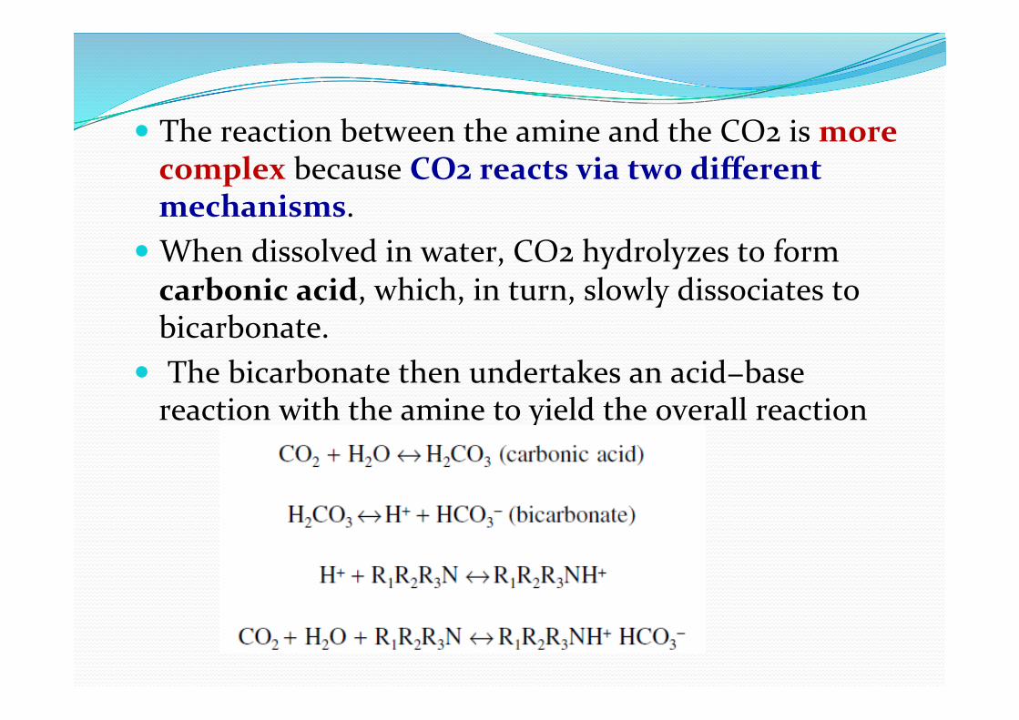
! The reaction between the amine and the CO2 is more complex because CO2 reacts via two different mechanisms.
! When dissolved in water, CO2 hydrolyzes to form carbonic acid, which, in turn, slowly dissociates to bicarbonate.
! The bicarbonate then undertakes an acid−base reaction with the amine to yield the overall reaction
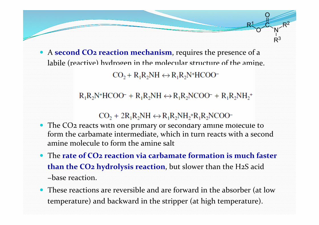
! A second CO2 reaction mechanism, requires the presence of a labile (reactive) hydrogen in the molecular structure of the amine.
! The CO2 reacts with one primary or secondary amine molecule to form the carbamate intermediate, which in turn reacts with a second amine molecule to form the amine salt
! The rate of CO2 reaction via carbamate formation is much faster than the CO2 hydrolysis reaction, but slower than the H2S acid−base reaction.
! These reactions are reversible and are forward in the absorber (at low temperature) and backward in the stripper (at high temperature).
Monoethanolamine ! Monoethanolamine (MEA) is the most basic of the amines used in acid treating and thus the most reactive for acid gas removal.
! It has the advantage of a high solution capacity at moderate concentrations, and it is generally used for gas streams with moderate levels of CO2 and H2S when complete removal of both impurities is required.
! A slow production of “heat stable salts” form in all alkanol amine solutions, primarily from reaction with CO2.
! Oxygen enhances the formation of the salts.

MEA Reac>ons
! 2(RNH2) + H2S ↔ (RNH3)2S ! (RNH3)2S + H2S ↔ 2(RNH3)HS ! 2(RNH2) + CO2 ↔ RNHCOONH3R
Some Representa>ve Opera>ng Parameters for Amine Systems
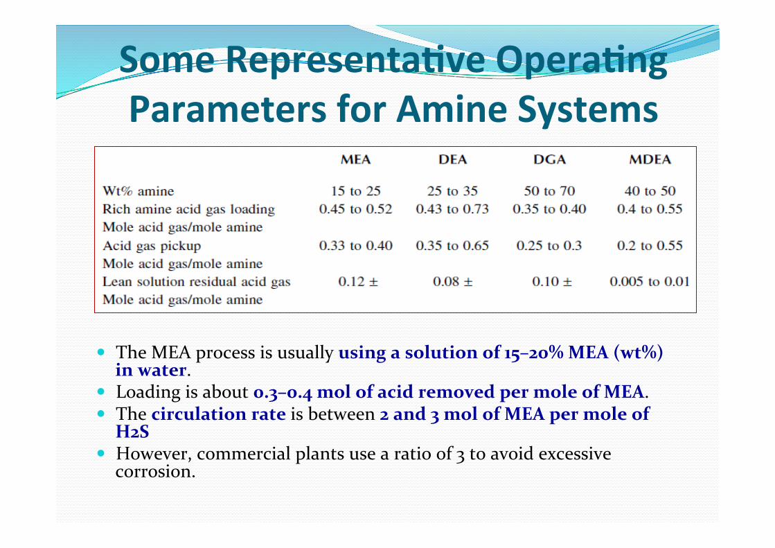
! The MEA process is usually using a solution of 15–20% MEA (wt%) in water.
! Loading is about 0.3–0.4 mol of acid removed per mole of MEA. ! The circulation rate is between 2 and 3 mol of MEA per mole of
H2S ! However, commercial plants use a ratio of 3 to avoid excessive
corrosion.
Monoethanolamine Disadvantages ! A relatively high vapor pressure that results in high vaporization losses
! The formation of irreversible reaction products with COS and CS2
! A high heat of reaction with the acid gases that results in high energy requirements for regeneration
! The inability to selectively remove H2S in the presence of CO2
! Higher corrosion rates than most other amines if the MEA concentration exceeds 20% at high levels of acid gas loading (Kohl and Nielsen, 1997)
! The formation of corrosive thiosulfates when reacted with oxygen (McCartney, 2005)

Opera>ng Features ! MEA forms foam easily due to the presence of contaminants in the liquid
phases; this foam results in carryover from the absorber. These contaminants could be condensed hydrocarbons, degradation products, iron sulfide, as well as corrosion products and excess inhibitors.
! Solids can be removed by using a filter; hydrocarbons could be flashed; degradation products are removed using a reclaimer.
! The number of trays used in absorbers in commercial units is between 20 and 25 trays. However, the theoretical number of trays calculated from published equilibrium data is about three to four.
! If we assume an efficiency of 35% for each tray, then the actual number of trays is 12. It has been reported that the first 10 trays pick up all of the H2S and at least another 10 trays are of not much value. Thus, it is suggested to use 15 trays.
! It is recommended that MEA be used if the feed does not contain COS or CS2, which form stable products and deplete the amine. If the feed has these compounds, a reclaimer must be used, where a strong base like NaOH is used to regenerate and liberate the amine. This base has to be neutralized later.

Diglycolamine ! Compared with MEA, low vapor pressure allows Diglycolamine [ 2-‐(2-‐aminoethoxy) ethanol] (DGA) to be used in relatively high concentrations (50 to 70%),
! Which results in lower circulation rates. ! It is reclaimed onsite to remove heat stable salts and reaction products with COS and CS2.
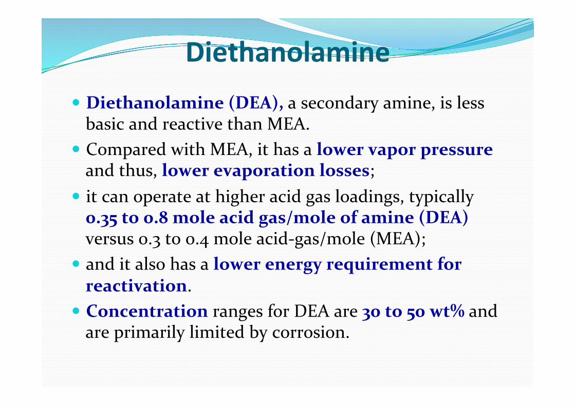
Diethanolamine ! Diethanolamine (DEA), a secondary amine, is less basic and reactive than MEA.
! Compared with MEA, it has a lower vapor pressure and thus, lower evaporation losses;
! it can operate at higher acid gas loadings, typically 0.35 to 0.8 mole acid gas/mole of amine (DEA) versus 0.3 to 0.4 mole acid-‐gas/mole (MEA);
! and it also has a lower energy requirement for reactivation.
! Concentration ranges for DEA are 30 to 50 wt% and are primarily limited by corrosion.

DEA Reac>ons ! 2R2NH + H2S ↔ (R2NH2)2S ! (R2NH2)2S + H2S ↔ 2R2NH2SH ! 2R2NH + CO2 ↔ R2NCOONH2R2

! DEA forms regenerable compounds with COS and CS2 and, thus, can be used for their partial removal without significant solution loss.
! DEA has the disadvantage of undergoing irreversible side reactions with CO2 and forming corrosive degradation products; thus, it may not be the best choice for high CO2 gases.
! Removal of these degradation products along with the heat stable salts must be done by use of either vacuum distillation or ion exchange.
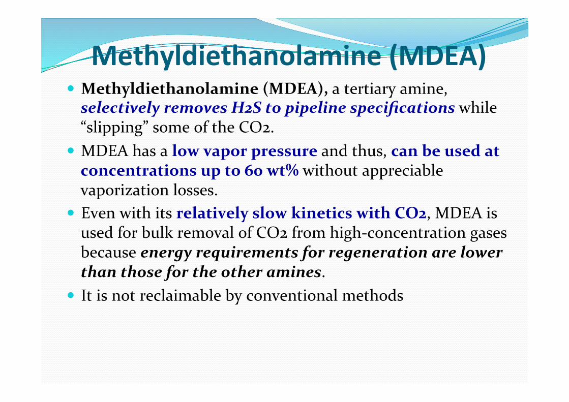
Methyldiethanolamine (MDEA) ! Methyldiethanolamine (MDEA), a tertiary amine, selectively removes H2S to pipeline specifications while “slipping” some of the CO2.
! MDEA has a low vapor pressure and thus, can be used at concentrations up to 60 wt% without appreciable vaporization losses.
! Even with its relatively slow kinetics with CO2, MDEA is used for bulk removal of CO2 from high-‐concentration gases because energy requirements for regeneration are lower than those for the other amines.
! It is not reclaimable by conventional methods
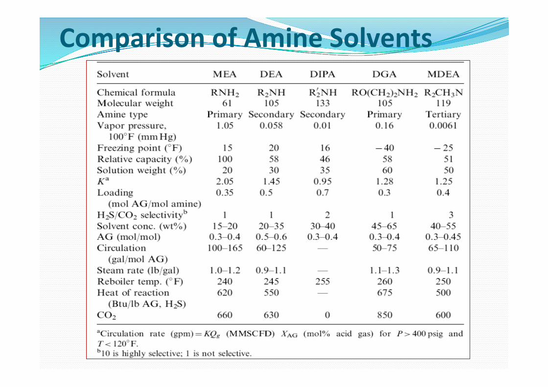
Comparison of Amine Solvents
Principles of Amine Trea>ng Process ! The acid gas is fed into a scrubber to remove entrained water and
liquid hydrocarbons. ! The gas then enters the bottom of absorption tower which is
either a tray (for high flow rates) or packed (for lower flow rate). ! The sweet gas exits at the top of tower. ! The regenerated amine (lean amine) enters at the top of this
tower and the two streams are contacted countercurrently. In this tower, CO2 and H2S are absorbed with the chemical reaction into the amine phase.
! The exit amine solution, loaded with CO2 and H2S, is called rich amine.
! This stream is flashed, filtered, and then fed to the top of a stripper to recover the amine, and acid gases (CO2 and H2S) are stripped and exit at the top of the tower.
! The refluxed water helps in steam stripping the rich amine solution.
! The regenerated amine (lean amine) is recycled back to the top of the absorption tower.
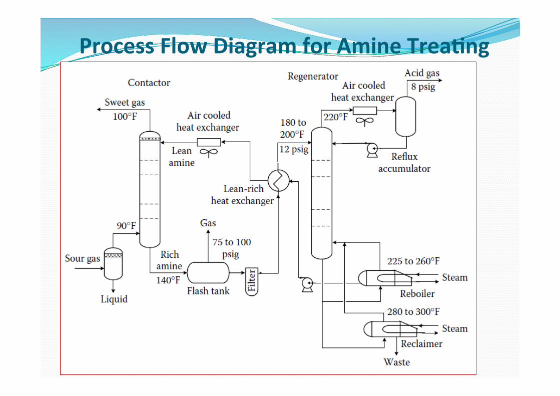
Process Flow Diagram for Amine Trea>ng
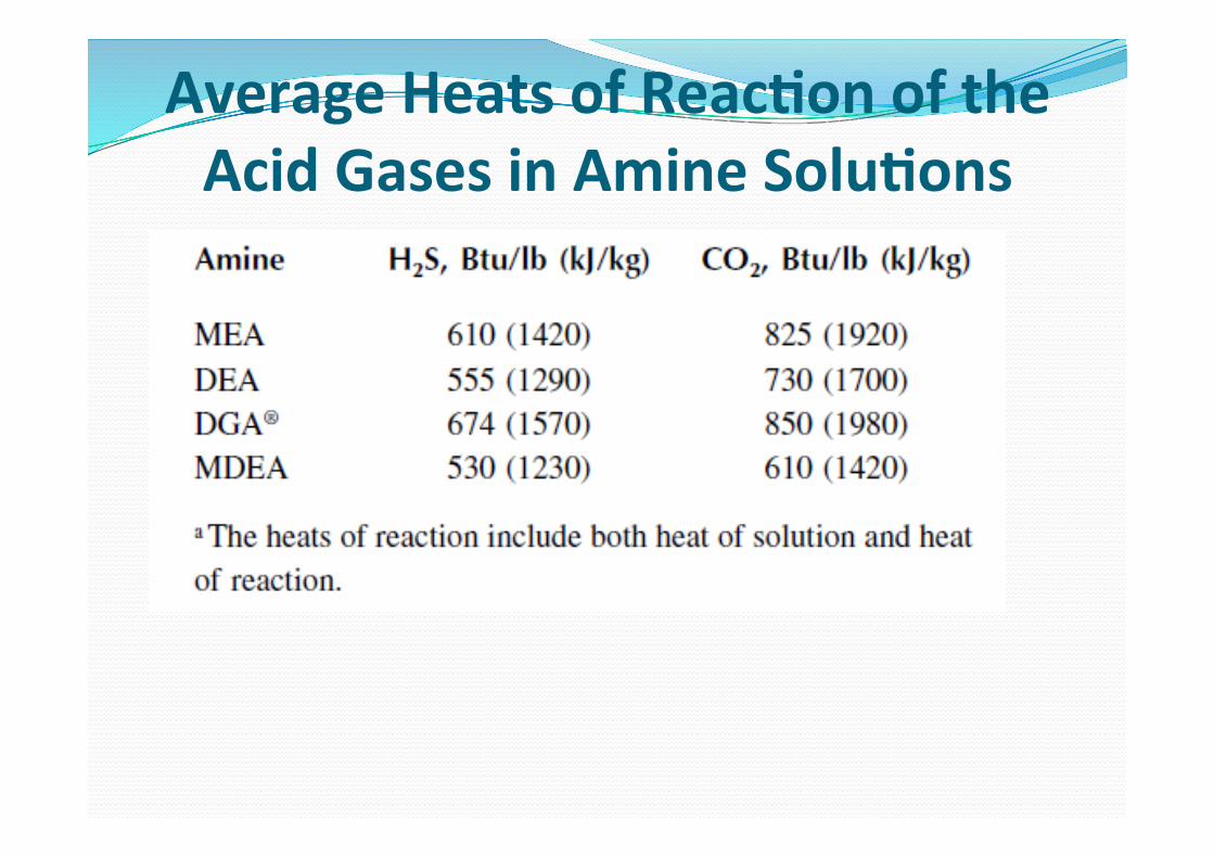
Average Heats of Reac>on of the Acid Gases in Amine Solu>ons
Amine Reclaiming ! Amines react with CO2 and contaminants, including oxygen, ! to form organic acids.
! These acids then react with the basic amine to form heat stable salts (HSS). As their name implies, these salts are heat stable, accumulate in the amine solution, and must be removed.
! For MEA and DGA solutions, the salts are removed through the use of a reclaimer which utilizes a semicontinuous distillation
! The reclaimer is filled with lean amine, and a strong base, such as sodium carbonate or sodium hydroxide, is added to the solution to neutralize the heat stable salts.
Opera>ng Issues ! Corrosion—Some of the major factors that affect corrosion are: ! Amine concentration (higher concentrations favor corrosion)
! Rich amine acid gas loading (higher gas loadings in the amine favor corrosion)
! Oxygen concentration ! Heat stable salts (higher concentrations promote corrosion and foaming)
! the corrosion products can cause foaming
! Solution Foaming— ! Foaming of the liquid amine solution is a major problem because it results in: " poor vapor−liquid contact, " poor solution distribution, " and solution holdup with resulting carryover and off spec gas.
! Among the causes of foaming are: " suspended solids, " liquid hydrocarbons, " surface active agents, such as those contained in inhibitors and compressor oils,
" and amine degradation products, including heat stable salts. ! One obvious cure is to remove the above materials; the other is to add antifoaming agents.
ALKALI SALTS ! Hot potassium carbonate (K2CO3) is used to remove both CO2 and H2S.
! Best for the CO2 partial pressure is in the range 30–90 psi.
! The process is very similar in concept to the amine process, in that after physical absorption into the liquid, the CO2 and H2S react chemically with the solution
! In a typical application, the contactor will operate at approximately 300 psig (20 barg), with the lean carbonate solution entering near 225°F (110°C) and leaving at 240°F (115°C).
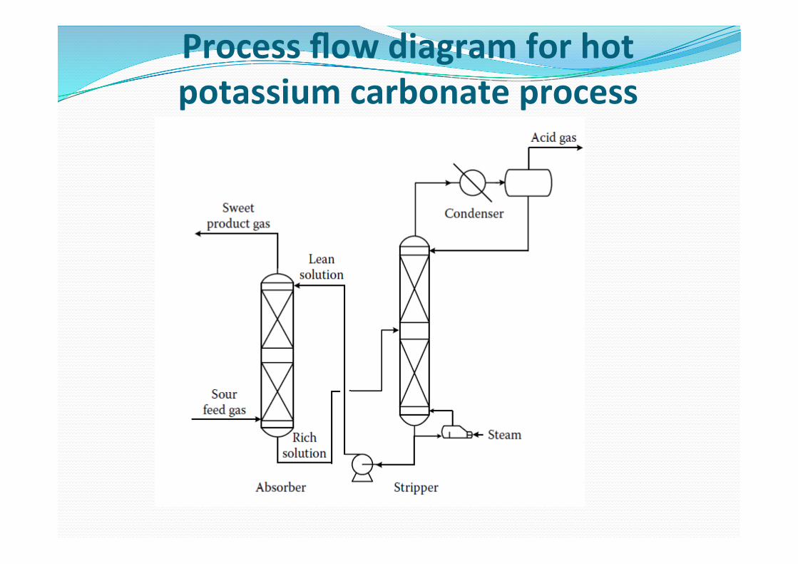
Process flow diagram for hot potassium carbonate process

Batch Processes for Sweetening
! Iron Sponge (Fe2O3) ! Zink Oxide (ZnO) ! Molecular Sieve (crystalline sodium alumino silicates)
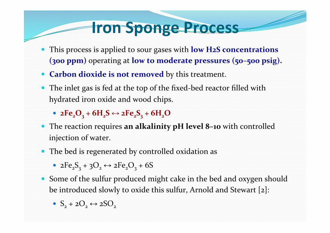
Iron Sponge Process ! This process is applied to sour gases with low H2S concentrations
(300 ppm) operating at low to moderate pressures (50–500 psig).
! Carbon dioxide is not removed by this treatment.
! The inlet gas is fed at the top of the fixed-‐bed reactor filled with hydrated iron oxide and wood chips.
! 2Fe2O3 + 6H2S ↔ 2Fe2S3 + 6H2O
! The reaction requires an alkalinity pH level 8–10 with controlled injection of water.
! The bed is regenerated by controlled oxidation as
! 2Fe2S3 + 3O2 ↔ 2Fe2O3 + 6S
! Some of the sulfur produced might cake in the bed and oxygen should be introduced slowly to oxide this sulfur, Arnold and Stewart [2]:
! S2 + 2O2 ↔ 2SO2
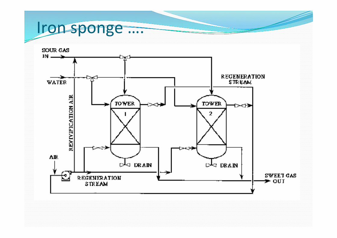
Iron sponge ….

Zinc Oxide ! Zinc oxide can be used instead of iron oxide for the removal of H2S, COS, CS2, and mercaptans.
! However, this material is a better sorbent and the exit H2S concentration can be as low as 1 ppm at a temperature of about 300 oC.
! The zinc oxide reacts with H2S to form water and zinc sulfide: ! ZnO + H2S ↔ ZnS + H2O
! A major drawback of zinc oxide is that it is not possible to regenerate it to zinc oxide on site, because active surface diminishes appreciably by sintering.
! Much of the mechanical strength of the solid bed is lost due to fines formation, resulting in a high-‐pressure-‐drop operation.
Molecular Sieve ! Molecular sieves (MSs) are crystalline sodium alumino silicates (Al/Si) and have very large surface areas and a very narrow range of pore sizes.
! They possess highly localized polar charges on their surface that act as adsorption sites for polar materials at even very low concentrations.
! This is why the treated natural gas could have very low H2S concentrations (4 ppm).
! In order for a molecule to be adsorbed, it first must be passed through a pore opening and then it is adsorbed on an active site inside the pore.
! There are four major zones in a sieve bed
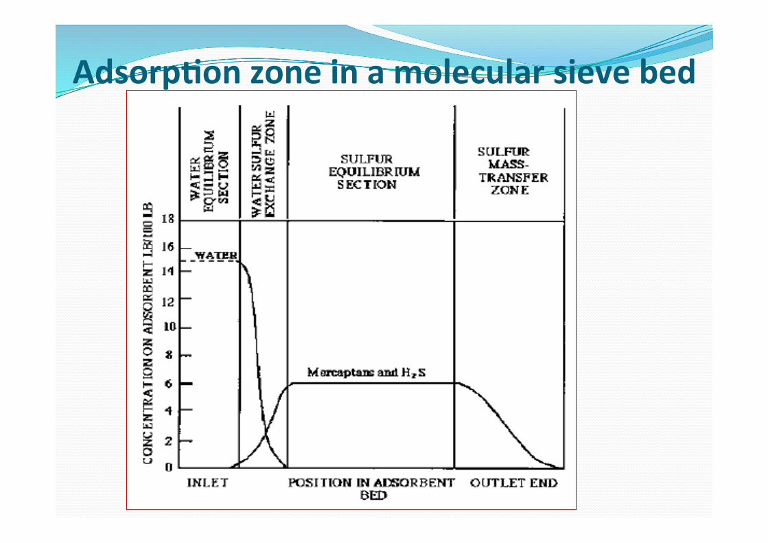
Adsorp>on zone in a molecular sieve bed

Sweetening of natural gas by molecular sieves

! If it is desired to remove H2S, a MS of 5 A* is selected ! If it is also desired to remove mercaptans, 13 X* is selected.
! In either case, selection made to minimize the catalytic reaction: ! H2S + CO2 ↔ COS + H2O
! Olefins, aromatics, and glycols are strongly adsorbed, which may poison the sieves.