Embed Size (px)
Citation preview

AUDIBLE ALARM CONTROLS PNEUMERCATORLiquid Level Control Systems
INSTRUCTION MANUAL
Revised: February 5, 2018
LC1000-A SERIES INTRINSICALLY SAFE
ALARM CONSOLE
© COPYRIGHT 2018 PNEUMERCATOR CO., INC. 1785 EXPRESSWAY DRIVE NORTH
HAUPPAUGE, NY 11788
(631) 293-8450 Phone (631) 293-8533 Fax
(800) 209-7858 Support www.pneumercator.com
LC1000-A Instruction Manual.docx
DRAWING NO. 20215 REV. A


LC1000-A INSTRUCTION MANUAL TABLE OF CONTENTS
TABLE OF CONTENTS
Page
Safety Information ................................................................................................ 5
Section 1 PRODUCT DESCRIPTION 1.1 General System Overview .................................................................................... 6 1.2 Control Console Description ................................................................................. 7 1.3 Liquid Sensor Description ................................................................................... 10
Section 2 INSTALLATION DETAILS
2.1 Installation Checklist ........................................................................................... 13 2.2 Control Console Installation ................................................................................ 14 2.3 Leak Sensor Installation – Steel Tanks ............................................................... 16 2.4 Leak Sensor Installation – Piping Sumps and Dispenser Pans, Vaulted Tank .... 17 2.5 Leak Sensor Installation – Fiberglass Underground Tanks ................................. 18 2.6 Other Dry Contact Float Switches ....................................................................... 19
Section 3 WIRING INSTALLATION
3.1 PC Board Setup and Layout ............................................................................... 20 3.2 System Wiring .................................................................................................... 22 3.3 Sensor Map/System Setup ................................................................................. 25 3.4 Installation as a Remote Alarm Panel ................................................................. 25
Section 4 OPERATION
4.1 General .............................................................................................................. 26 4.2 Horn Control ....................................................................................................... 26
Section 5 TROUBLESHOOTING
5.1 General .............................................................................................................. 27 5.2 Spare Parts List .................................................................................................. 27
Section 6 MAINTENANCE/TESTING
6.1 Console .............................................................................................................. 28 6.2 Sensors .............................................................................................................. 28
Appendix WIRING/SPECIFICATIONS ................................................................................ 29
Wiring Diagrams ........................................................................................................ 29 Specifications ............................................................................................................ 31


LC1000-A INSTRUCTION MANUAL SAFETY
PAGE 5
IMPORTANT SAFETY INFORMATION
This manual contains instructions for installing electrical hardware in explosion hazard areas. The following warnings must be considered to be in compliance with accepted codes. Any inquiries about this manual, or to return defective equipment should be directed to:
PNEUMERCATOR COMPANY 1785 EXPRESSWAY DRIVE NORTH
HAUPPAUGE, NY 11788 Attention: Technical Services
TEL: (631) 293-8450 FAX: (631) 293-8533
TOLL FREE: (800) 209-7858 www.pneumercator.com
WARNING
Installation must be in strict accordance with this manual as adopted from the following codes: - ISA RP12.6, "Installation of intrinsically Safe Instrument Systems in Class I Hazardous Locations." - FM – FM Approvals - NFPA 70, "National Electric Code." - NFPA 30A, "Automotive and Marine Service Station Code." FAILURE TO COMPLY MAY RESULT IN PERSONAL INJURY, PROPERTY LOSS AND EQUIPMENT DAMAGE.
WARNING
Alteration, modification or replacement with non-factory components could impair the intrinsic safety of this equipment, void the warranty and void the FM Listing. FAILURE TO COMPLY MAY RESULT IN PERSONAL INJURY, PROPERTY LOSS AND EQUIPMENT DAMAGE.

LC1000-A INSTRUCTION MANUAL PRODUCT DESCRIPTION
PAGE 6
SECTION 1 – PRODUCT DESCRIPTION 1.1 GENERAL SYSTEM OVERVIEW The basic function of the Model LC1000-A Alarm console is to provide both audible and visual warning alarms at the occurrence of high, low, or leak conditions: typically via float switches, or any tank mounted sensing device that transmits an alarm condition by opening or closing dry switch contacts. The LC1000-A may also be used as a non-intrinsically safe remote alarm panel for any system that provides a dry contact relay output to represent a specific set of conditions. The console is equipped with an AutoSwitching Power Supply that supports 95-250 VAC. It is equipped with a Power LED and also provides 1 to 4 input channels each with a corresponding LED. Each input consists of a pair of intrinsically safe terminals for wiring to field mounted switches. The intrinsically safe inputs allow mounting the switches in explosion hazard environments without requiring additional protective barrier components in the wiring runs. For every input, there is a single dry contact relay output that can be used to signal a remote alarm device or control an external electrical device, such as a solenoid valve. Confirm the electrical specifications of the load do not exceed the maximum support of the relay output as listed in the Appendix in the back of this manual.
Figure 1-1 - LC1000-A Series Overview
DRAWING NO. 20216 REV. N/C
RESET TEST
AC POWER
LEAK OVERFILL
LIQUID STORAGE TANK OVERFILL/LEAK ALARM SYSTEM OVERVIEW
LC1000-A-03-20-0 CONSOLE
(MOUNT OUTSIDE
HAZARDOUS AREA)
90% CAPACITY
TYPICAL
LEAK SENSOR
OVERFILL
LEVEL
SWITCHTESTRESET
RELAY
OUTPUTS
TANK SUMP HIGH
LEAK LEAK
FIBERGLASS STORAGE TANK OVERFILL/LEAK ALARM SYSTEM OVERVIEW
HIGH LEVEL SWITCH
TYPICAL DOUBLE WALL TANK
(OR SECONDARY
CONTAINMENT)
90% CAPACITY
TYPICAL
TYPICAL FIBERGLASS
DOUBLE WALL TANK
RELAY OUTPUT
LIQUID FILLED RESERVOIR
LEAK SENSOR
PIPING SUMP
LEAK SENSOR
RE
LA
Y
OU
TP
UT
S
AC POWER
LC1000-A-03-30-0 CONSOLE
(MOUNT OUTSIDE
HAZARDOUS AREA)
LC1000-A INSTRUCTION MANUAL PRODUCT DESCRIPTION
PAGE 7
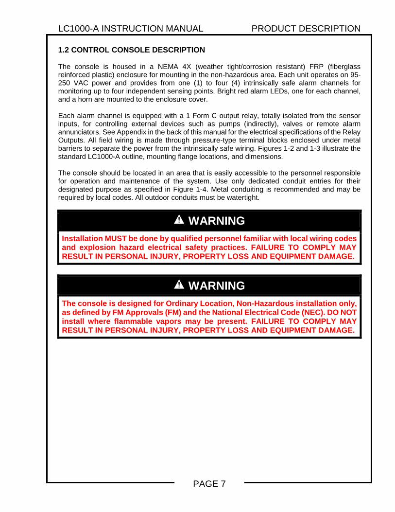
1.2 CONTROL CONSOLE DESCRIPTION The console is housed in a NEMA 4X (weather tight/corrosion resistant) FRP (fiberglass reinforced plastic) enclosure for mounting in the non-hazardous area. Each unit operates on 95-250 VAC power and provides from one (1) to four (4) intrinsically safe alarm channels for monitoring up to four independent sensing points. Bright red alarm LEDs, one for each channel, and a horn are mounted to the enclosure cover. Each alarm channel is equipped with a 1 Form C output relay, totally isolated from the sensor inputs, for controlling external devices such as pumps (indirectly), valves or remote alarm annunciators. See Appendix in the back of this manual for the electrical specifications of the Relay Outputs. All field wiring is made through pressure-type terminal blocks enclosed under metal barriers to separate the power from the intrinsically safe wiring. Figures 1-2 and 1-3 illustrate the standard LC1000-A outline, mounting flange locations, and dimensions. The console should be located in an area that is easily accessible to the personnel responsible for operation and maintenance of the system. Use only dedicated conduit entries for their designated purpose as specified in Figure 1-4. Metal conduiting is recommended and may be required by local codes. All outdoor conduits must be watertight.
WARNING
Installation MUST be done by qualified personnel familiar with local wiring codes and explosion hazard electrical safety practices. FAILURE TO COMPLY MAY RESULT IN PERSONAL INJURY, PROPERTY LOSS AND EQUIPMENT DAMAGE.
WARNING
The console is designed for Ordinary Location, Non-Hazardous installation only, as defined by FM Approvals (FM) and the National Electrical Code (NEC). DO NOT install where flammable vapors may be present. FAILURE TO COMPLY MAY RESULT IN PERSONAL INJURY, PROPERTY LOSS AND EQUIPMENT DAMAGE.

LC1000-A INSTRUCTION MANUAL PRODUCT DESCRIPTION
PAGE 8
Figure 1-2 - LC1000-A Console Outline (1-2 Channel)
Figure 1-3 - LC1000-A Console Outline (3-4 Channel)
DRAWING NO. 20217 REV. A
(3) Ø.844 [Ø21] HOLES FOR1/2" NPT OR EQUIVALENT
CONDUIT FITTINGS
334 [95]
4 [102]
11516 [49]
1 916 [40]
834
[222]912
[242]
558 [143]
41516 [125]
7 516 [186]
RESET TESTTESTRESET
RESETPUSHBUTTON
TESTPUSHBUTTON
ANNUNCIATOR
INDICATORLIGHT
(2) INDICATORLIGHTS
OPTIONAL 316 STAINLESSSTEEL PADLOCK LATCH
Ø.375 PADLOCK EYE
DIMENSIONS: INCHES [MM]
(4) Ø 516 [Ø8]
MOUNTINGHOLES
POWER LIGHT
458 [118]
DRAWING NO. 20218 REV. A
DIMENSIONS: INCHES [MM]
(3) INDICATOR LIGHTS (4) INDICATOR LIGHTS
TESTPUSHBUTTON
RESETPUSHBUTTON
(5) Ø.844 [21] HOLES FOR1/2" NPT OR EQUIVALENT
CONDUIT FITTINGS
RESET TEST RESET TEST
11716 [291]
6 [153]
9516
[236]
1034 [272]
618 [156]
5 716 [138]
158 [41]
218 [54]
438 [111]
634 [171]
8 916 [217]
(4) Ø516 [Ø8]
MOUNTINGHOLES
ANNUNCIATOR
POWER LIGHT
9 716 [240]
OPTIONAL 316 STAINLESSSTEEL PADLOCK LATCH
Ø.375 PADLOCK EYE

LC1000-A INSTRUCTION MANUAL PRODUCT DESCRIPTION
PAGE 9
WARNING
Do not drill or modify enclosure. Use only conduit entries provided. FAILURE TO COMPLY WILL VOID WARRANTY AND MAY PRESENT A SAFETY HAZARD RESULTING IN PERSONAL INJURY, PROPERTY LOSS AND EQUIPMENT DAMAGE.
WARNING
Conduit entries must only be used for their designated purpose in order to assure safe operation and to maintain safety certification. FAILURE TO COMPLY WILL VOID WARRANTY AND MAY PRESENT A SAFETY HAZARD RESULTING IN PERSONAL INJURY, PROPERTY LOSS AND EQUIPMENT DAMAGE.
Figure 1-4 - LC1000-A Conduit Usage
DRAWING NO. 20219 REV. N/C
NON-INTRINSICALLY SAFE
CONDUIT OPENINGS ANDDESIGNATED USES:
1/2" NPT CONDUIT SIZE *
ALL MODELS:
A = POWER AND EARTH GROUNDS
B = RELAY OUTPUT(S)
LC1000-A-[ ]-30-[ ] OR LC1000-A-[ ]-40-[ ]:
D = RELAY OUTPUTS
1/2" NPT CONDUIT SIZE *
ALL MODELS:
C = I.S. INPUT(S)
LC1000-A-[ ]-30-[ ] OR LC1000-A-[ ]-40-[ ]:
E = I.S. INPUTS
INTRINSICALLY SAFE
CONDUIT OPENINGS ANDDESIGNATED USES:
* OR EQUIVALENT
E C
C A
D A
MODELS
LC1000-A-[ ]-10-[ ] OR
LC1000-A-[ ]-20-[ ]
MODELS
LC1000-A-[ ]-30-[ ] OR
LC1000-A-[ ]-40-[ ]
B
B

LC1000-A INSTRUCTION MANUAL PRODUCT DESCRIPTION
PAGE 10
1.3 LIQUID SENSOR DESCRIPTION The LC1000-A can be integrated with a variety of liquid sensors used for monitoring in-tank levels and secondary containment areas around tanks and pipes. The maximum is 4 sensors depending on the overall job configuration; check the specific job design drawings for the actual number and type specified. Figures 1-5 through 1-8 show four (4) sensor types provided by Pneumercator with their most typical applications. Other non-Pneumercator models may be used; however, their use with the LC1000-A should have been approved by Pneumercator and local regulators before attempting to wire them into the system.
Figure 1-5 – LS600 LD Series
Commonly used in Sumps, Dispenser Pans, and Steel Tank Interstitial Spaces
Figure 1-6 – LS610 Commonly used in Dry Interstitial Spaces of Fiberglass Tanks
DRAWING NO. 20006 REV. D
4.00"[102]
Ø1.50"[38]
Ø1.75"[45]
1/2" [13] LIQUIDTRIP POINT
304 STAINLESSSTEEL
BUNA NFLOAT
NYLON
25' (7.5M) LONG
22AWG [.762 DIA.]2-CONDUCTOR
CABLE
TEFLON
304 STAINLESSSTEEL
316 STAINLESSSTEEL FLOAT
LS600LDBN-1 LS600LDSS
4.00"[102]
1/2" [13] LIQUIDTRIP POINT
DIMENSIONS: INCHES [MM]
DIMENSIONS: FEET (M)
CABLE GRIP CABLE GRIP
25' (7.5M) LONG
22AWG [.762 DIA.]2-CONDUCTOR
CABLE
DRAWING NO. 20008 REV. A
.236 [6] REF.
.40" [10]
3.02" [77]
1.50" [38]
Ø.130" [3.3]
PULL HOLE
1/2" [13] LIQUID
TRIP POINT
CABLE GRIP
25' (7.5M) LONG
CABLE
DIMENSIONS: INCHES [MM]
DIMENSIONS: FEET (M)

LC1000-A INSTRUCTION MANUAL PRODUCT DESCRIPTION
PAGE 11
Figure 1-7 – LS600 Series
(Refer to Bulletin 193 for Installation/Operation/Testing Instructions) Commonly used for Overfill Protection
May also be used for Low alarms and Indirect Pump On/Pump Off Conditions See PC1000 literature for direct pump control applications
DRAWING NO. 20057 REV. A
SL
1/2" NPT THREADED OPENING
MAX. DIA. 1.63"
3" REF
S.S. RETAINING CLIP
2 REQ'D PER FLOAT
LIFT GUIDE
SL
ADDITIONAL LIFT GUIDE FOR
UNITS WHERE SENSING
LENGTH "SL" EXCEEDS 18"
2" REF(3" REF WHEN
FLOAT IS
LIFTED)
5" REF.
5 1/2"REF.
S.S. OR BRASS
FITTING
S.S. FLOAT
MAX. DIA. 1.92"
S.S. RETAINING CLIP
2 REQ'D PER FLOAT
S.S. OR BRASS
FITTINGS.S. OR BRASS
FITTING
S.S. OR BRASS
FITTING
(2) 2' LONG (10' FOR LS600A MODELS)
18 AWG WIRE LEADS PER
FLOAT SWITCH
(2) 10' LONG 18 AWG
WIRE LEADS
ADDITIONAL
FLOATS FOR
CUSTOM UNITSS.S. OR BRASS SHAFT
MAX. LENGTH 192" S.S.
AND 144" BRASS
SEAL FITTING
S.S. LIFT ROD
BUSHING
(2" NPT)
LS600A NCLLS600, LS600 OW OR LS600A *
BUNA-N FLOAT
DIA.1.75"
S.S. OR BRASS SHAFT
MAX. LENGTH 192" S.S.
AND 144" BRASS
BUSHING
(2" NPT)
NIPPLE
HOUSING
3" MIN.
3" MIN.
1/2" MIN.
4"REF
1/2" MIN.
OPTIONAL S.S. FLOAT FOR
2" OR 1 1/2" NPT OPENINGS
INSIDE WALL OF
TANK BOTTOM
L L
S *
5/8" THREADENGAGEMENT
S *
5/8" THREADENGAGEMENT
3" REF.
* LS600 OW SERIES SUPPLIED WITH STAINLESS FLOATS.HOUSING, NIPPLE & BUSHING NOT SUPPLIED ON LS600A SERIES.
CUSTOM MINIATURE LS600s ARE AVAILABLE FOR SUB
BASE OR GENERATOR TANKS THAT REQUIRE SET
POINTS TO BE CLOSER TOGETHER AND/OR TANKS
WITH SMALLER THREADED OPENINGS. SEE OUTLINE
DRAWING 10620.
NOTE
LC1000-A INSTRUCTION MANUAL PRODUCT DESCRIPTION
PAGE 12
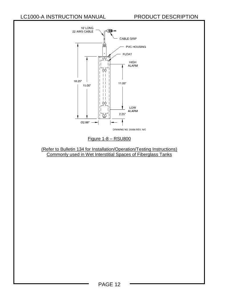
Figure 1-8 – RSU800
(Refer to Bulletin 134 for Installation/Operation/Testing Instructions) Commonly used in Wet Interstitial Spaces of Fiberglass Tanks
DRAWING NO. 20056 REV. N/C
16' LONG22 AWGCABLE
18.25"
15.00"
CABLE GRIP
PVC HOUSING
11.00"
Ø2.88"
2.25"
HIGHALARM
LOWALARM
FLOAT

LC1000-A INSTRUCTION MANUAL INSTALLATION DETAILS
PAGE 13
SECTION 2 – INSTALLATION DETAILS 2.1 INSTALLATION CHECKLIST
WARNING
Do NOT apply power to the LC1000-A until its installation has been checked and found to be in accordance with these instructions; National Electric Code; Federal, State and Local codes; and other applicable safety codes. FAILURE TO COMPLY MAY RESULT IN PERSONAL INJURY, PROPERTY LOSS AND EQUIPMENT DAMAGE.
The following points should be reviewed in preparation for installation, and again when installation is complete.
1. Review Figures 3-2 and/or 3-3 to ensure that all of the safety/wiring requirements have been met.
2. Check that all equipment at job site matches the DESIGN DRAWING SPECIFICATIONS for
the tank sizes and control features required.
3. The console should be located as close as possible to the demarcation point of the hazardous area. Never mount inside the hazardous area. Note: If the LC1000-A was provided with a NEMA 7 Explosion-proof enclosure, then it is permitted to install the LC1000-A in the hazardous location provided that all fittings and conduit are explosion-proof and all applicable regulations are followed.
4. POWER to the console should be properly wired to a DEDICATED 120/240 VAC CIRCUIT
BREAKER. No other equipment can be powered from the same circuit breaker as the LC1000-A console.
5. System cannot be connected to equipment that uses or generates more than 250 volts with
respect to earth.
6. All LC1000-A grounds must be terminated at the GND BUSS BAR in the same service panel as LC1000-A power. A grounding rod, coldwater pipe or other connection should not be used.
7. Do not drill or modify enclosure. Use only conduit entries provided. Failure to comply will
void warranty and may present a safety hazard.
8. WATERPROOFING FIELD WIRE SPLICES using factory supplied splice kits is required for proper system operation.

LC1000-A INSTRUCTION MANUAL INSTALLATION DETAILS
PAGE 14
2.2 CONTROL CONSOLE INSTALLATION The console is the center of operations for any tank monitor system therefore its location should be selected for the operator’s convenience, or as specified on the DESIGN DRAWINGS. Select a flat wall surface and prepare it with four wall-mounting inserts to accept up to 1/4-inch size bolts. Allow sufficient room for door to open and for conduit runs to enter ONLY THE CONSOLE BOTTOM. See Figures 1-2 or 1-3 for the appropriate console dimensions.
Note that the console is divided into two electrical areas: INTRINSICALLY SAFE (LEFT SIDE) NON INTRINSICALLY SAFE (RIGHT SIDE) for Sensor signals and IS Earth Grounds for Power and Control
Figures 2-1 and 2-2 show the console interior, again indicating the power and signal separation. THIS SEPARATION MUST BE MAINTAINED when conduits are connected. Refer to Section 3 for electrical conduit and wiring.
Figure 2-1 – LC1000-A Single Board Control Console Interior (2-channel configuration shown)
DRAWING NO. 20220 REV. A
FUSE
I.S. COMPARTMENT
(COVER OPENED)
MOUNTING PLATE
I.S. INPUT 1
FOR LC1000-A-[ ]-10-[ ]
SPACER
POWER
I.S. GROUNDS
I.S. COMPARTMENT COVER
(SHOWN CLOSED)
POWER SUPPLY COVER
NON I.S. OUTPUT 1
FOR LC1000-A-[ ]-10-[ ]I.S. INPUTS 1 & 2
FOR LC1000-A-[ ]-20-[ ]
NON I.S. OUTPUTS 1 & 2
FOR LC1000-A-[ ]-30-[ ]
CONDUIT GROUNDING PLATE
FUSE
HOLDER
FUSE COVER
COVER CAPTIVE SCREW

LC1000-A INSTRUCTION MANUAL INSTALLATION DETAILS
PAGE 15
Figure 2-2 – LC1000-A Dual Board Control Console Interior (4-channel configuration shown)
DRAWING NO. 20221 REV. A
FUSE
FUSE
HOLDER
FUSE COVER
I.S. COMPARTMENT COVER
TYPICAL (2) PLACES
(SHOWN CLOSED)
COVER CAPTIVE SCREW
TYPICAL (2) PLACES
MOUNTING PLATE
SPACER
POWER
I.S. GROUNDS
POWER SUPPLY COVER
(2) CONDUIT GROUNDING PLATES
(2) I.S. COMPARTMENTS
(COVER OPENED)
BOARD #1 (LEFT)
I.S. INPUTS 1 & 2
FOR LC1000-A-[ ]-30-[ ]
& LC1000-A-[ ]-40-[ ]
BOARD #1 (LEFT)
NON I.S. OUTPUTS 1 & 2
FOR LC1000-A-[ ]-30-[ ]
& LC1000-A-[ ]-40-[ ]
BOARD #2 (RIGHT)
I.S. INPUT 1
FOR LC1000-A-[ ]-30-[ ]
BOARD #2 (RIGHT)
NON I.S. OUTPUT 1
FOR LC1000-A-[ ]-30-[ ]
BOARD #1 (LEFT)
I.S. INPUTS 1 & 2
FOR LC1000-A-[ ]-30-[ ]
& LC1000-A-[ ]-40-[ ]
BOARD #1 (LEFT)
NON I.S. OUTPUTS 1 & 2
FOR LC1000-A-[ ]-30-[ ]
& LC1000-A-[ ]-40-[ ]
BOARD #2 (RIGHT)
I.S. INPUTS 1 & 2
FOR LC1000-A-[ ]-40-[ ]
BOARD #2 (RIGHT)
NON I.S. OUTPUTS 1 & 2
FOR LC1000-A-[ ]-40-[ ]
(2) I.S. COMPARTMENTS
(COVER OPENED)
I.S. GROUND
INTERCONNECTIONS
BOARD #1 (LEFT)
DC POWER CABLE

LC1000-A INSTRUCTION MANUAL INSTALLATION DETAILS
PAGE 16
EXTERNAL LEAK SENSOR INSTALLATION
The interstitial or double-wall space of steel tanks and vaulted tanks as well as many other secondary containment areas can be fitted with leak sensors. Switch actuation may be factory set for either NORMALLY OPEN or NORMALLY CLOSED.
2.3 LEAK SENSOR INSTALLATION IN STEEL AND VAULTED TANKS
Check the specific design drawings for the job, or use the LS600LD Series as illustrated in Figure 1-5. Install sensor per Figure 2-3 as follows:
1. Remove the watertight CORD CONNECTOR supplied by sliding it off the sensor cable.
2. Thread the watertight CONNECTOR into the top of a 2" by 1/2" reducer bushing or monitor pipe cap pre-tapped for a 1/2" NPT hole. (The use of any standard monitor cap from 2" to 4" pipe size is recommended. The cap or reducer bushing IS NOT SUPPLIED with the sensor and must be provided by the installer. A 2” (SK2) or 4” (SK4) Sensor Cap Kit can be ordered separately from Pneumercator).
3. Measure the "MOUNTING HEIGHT" from top to bottom of monitoring pipe.
4. Feed the sensor cable through the watertight CONNECTOR from the BOTTOM SIDE of the REDUCER (or CAP) fitting to a cable length suitable for the MOUNTING HEIGHT; or to allow sensor to rest on the monitor pipe bottom; or as required by local codes. Cable may be cut or extended to proper length.
5. Re-tighten the CORD CONNECTOR to fix the sensor cable length.
6. Mate the REDUCER or CAP to the top of the monitor pipe. Tighten the CONNECTOR to ensure a WATERTIGHT SEAL.
7. Route the sensor cable to the junction box and complete the wiring installation in accordance with Section 3.
Figure 2-3 - Leak Sensor Installation - Steel Vaulted Tanks
DRAWING NO. 20016 REV. C
DOUBLE WALL TANK
WATERTIGHT JUNCTION BOX
AND CONDUIT SEALMONITOR PIPE
CAP OR
REDUCER
MOUNTING HEIGHT
12" MINIMUM MANHOLE
IS REQUIRED FOR
UNDERGROUND TANKS
2" OR LARGER
MONITORING PIPE
LEAK SENSOR

LC1000-A INSTRUCTION MANUAL INSTALLATION DETAILS
PAGE 17
2.4 LEAK SENSOR INSTALLATION IN PIPING SUMPS AND DISPENSER PANS Check the specific design drawings for the job, or use the LS600LD Series as illustrated in Figure 1-5. Install sensor per Figure 2-3 as follows: 1. Measure the "MOUNTING HEIGHT" from conduit or junction box to the bottom of the SUMP (or
MANHOLE, VAULT or DISPENSER PAN). 2. Feed the sensor cable through the watertight CONNECTOR to length suitable for the MOUNTING
HEIGHT; or to allow sensor to rest on the containment bottom; or as required by local codes. Feed an additional 12 inches past the CONNECTOR for splicing inside the junction box; cable may be cut to proper length.
3. Thread the CONNECTOR into the WATERTIGHT JUNCTION BOX and tighten the
CONNECTOR cord grip over the cable to insure a WATERTIGHT SEAL. The sensor should rest on the containment floor or as required by local codes.
4. Complete the wiring installation in accordance with Section 3.
Figure 2-4 - Leak Sensor Installation in Piping Sumps, Manholes, and Dispenser Pans
MOUNTING HEIGHT
SENSOR FLEXIBLE CABLE
LIQUID TIGHT
CABLE GRIP
WATERTIGHT JUNCTION BOX
AND CONDUIT SEAL
LEAK SENSOR
MANHOLE
PIPING SUMP OR
DISPENSER PAN
DRAWING NO. 20017 REV. D

LC1000-A INSTRUCTION MANUAL INSTALLATION DETAILS
PAGE 18
2.5 LEAK SENSOR INSTALLATION IN FIBERGLASS TANK ANNULUS The annular space of fiberglass tanks can be fitted with either a DRY ANNULUS type sensor, model LS610 (Figure 1-6), or a WET RESERVOIR sensor model RSU800 (Figure 1-8). The wet reservoir is also referred to as the HYDROSTATIC METHOD. Check the specific design drawings for the job, or choose the type sensor desired from Figures 1-6 or 1-8. Install LS610 sensor per Figure 2-5 or the separate document covering the RSU800: Bulletin 134. Instructions per Figure 2-5, DRY ANNULUS SENSOR: 1. Calculate the sensor cable's MOUNTING LENGTH from tank size data so the sensor rests at tank
bottom; or use the following method.
Determine the cable's MOUNTING LENGTH by adding the cable measurement M from the table at the right to the RISER HEIGHT. Mark the cable at that length. DO NOT CUT THE CABLE.
2. Remove the watertight CORD CONNECTOR
supplied by sliding it off the cable. 3. Thread the CONNECTOR into the top of a 2" by
1/2" reducer bushing or riser pipe cap pre-tapped for a 1/2" NPT hole. (The use of any standard monitor cap from 2" to 4" pipe size is recommended. The cap or reducer bushing IS NOT SUPPLIED with the sensor and must be provided by the installer. A 2” (SK2) or 4” (SK4) Sensor Cap Kit can be ordered separately from Pneumercator).
4. At riser top, attach the annular space PULL CORD (this is part of the tank supplier's pre-installed
accessories) to the sensor's PULL HOLE. 5. Pull the free end of the PULL CORD out of the riser while feeding the sensor into the riser and
through the annular space until the sensor is at the bottom centerline of the tank. The MOUNTING LENGTH MARK should be about 5 INCHES above the open riser. Adjust its position as necessary and, without disconnecting the PULL CORD, coil its excess inside the riser pipe.
6. Feed the sensor cable through the BOTTOM of the riser cap (or bushing), and through the CORD
CONNECTOR while positioning cap over the riser pipe. Mate riser and cap. 7. Tighten CONNECTOR over the cable to ensure a WATERTIGHT SEAL. 8. Complete the wiring installation in accordance with Section 3.
CABLE MEASUREMENT FROM END OF SENSOR
Tank Dia. Cable M 4 Feet 81 in. 6 Feet 118 in. 8 Feet 150 in. 10 Feet 194 in. 12 Feet 222 in.

LC1000-A INSTRUCTION MANUAL INSTALLATION DETAILS
PAGE 19
Figure 2-5 - Dry Leak Sensor Installation in Fiberglass Tanks
2.6 OTHER DRY CONTACT FLOAT SWITCHES
The LC1000-A has the electrical ability to read the continuity state of any dry contact sensor. As such, this system will support a variety of sensors from various manufacturers. However, your local regulations may not permit this combination as the LC1000-A has not been specifically approved for use with sensors not manufactured by Pneumercator. Please consult with your local regulators and with Pneumercator to discuss the compatibility of your particular sensor with the console and application. Some Pneumercator float switch sensors have been covered in their entirety within this Instruction Manual. Select models have separate Instruction Bulletins for specific installation and wiring instructions. Please see the list below for the specific bulletin numbers: RSU800-2 Bulletin 134 LS600 Series Bulletin 193 LS600-S Bulletin 195 2-wire splice kit Bulletin 179 3-wire splice kit Bulletin 180 These bulletins were supplied with each sensor and may also be downloaded from www.pneumercator.com by visiting the Tech Support section and scrolling down to Bulletins.
DRAWING NO. 20018 REV. D
RISER PIPE CAP W/LIQUID TIGHT CABLE GRIP
WATERTIGHT JUNCTION BOX ANDVAPOR SEAL
1/2" NPT LIQUID TIGHT CABLE GRIP(USE 1/2" X 3/8" NPT REDUCER FOR 3/8" CABLE GRIPS)
1/2" OR 3/4" CONDUIT TO CONSOLE
LEAK SENSOR CABLE
MANHOLE
RISER HEIGHT
PULL CORD
TANK ANNULUS
LEAK SENSOR
COIL & SECURE EXCESS PULL CORDDO NOT REMOVE THE PULL CORD
4" SCHEDULE 40 OR2" SCHEDULE 40RISER PIPE
OPTIONAL PADLOCK(BY CUSTOMER)

LC1000-A INSTRUCTION MANUAL WIRING
PAGE 20
SECTION 3 WIRING INSTALLATION 3.1 PC BOARD LAYOUT AND SETUP The LC1000-A Series includes either one (1-2 channels) or two (3-4 channels) PC boards within the enclosure. Each board is equipped with a set of switches for each channel to configure the sensor inputs and relay outputs to suit the particular application. The switches will be configured at the factory to match the sensors provided on the order. Figure 3-1 on the following page includes a table detailing the switch settings for configuring inputs and relay outputs. Each input may be configured to accept normally open or normally closed sensors. Below is a list of commonly used Pneumercator float switch sensors.
LS600* (Striped Wires): Open Circuit in a Dry Tank LS600* (Solid Color Wires (No Stripe)) Closed Circuit in a Dry Tank LS600LD: Normally Open LS610: Normally Closed RSU800: Normally Closed
* Normal contact state determined based on float being Normally Wet or Normally Dry All sensors will change the state of the corresponding relay upon activating. A DIP switch setting will identify the input as supporting an Alarm Sensor (activate the integrated horn) or a Relay Control Sensor (no effect on horn). Relay Control Sensors typically are used in conjunction with valve or indirect pump control applications. Failsafe relay operation (normally energized) is enabled by DIP switch. The default switch setting has failsafe relay mode disabled (normally de-energized). When acknowledging the internal LC1000-A horn by pressing the integrated Reset button, the state of the relay does not change from active to normal by default. The LC1000-A can be configured so that pressing the Reset button also returns the relay to its normal state. This is usually desired if a remote alarm system is connected to the LC1000-A relay. This feature is enabled by a DIP switch and is disabled by default. The standard Autosilence feature on the LC1000-A may silence the integrated horn after a time delay of 1 to 9 minutes. The S1 rotary switch is used to configure the time delay. Setting S1 to zero disables this feature and is the default setting. Note: Soldering on the boards is NOT permitted. ALL repairs to the boards must be performed at the factory.

LC1000-A INSTRUCTION MANUAL WIRING
PAGE 21
Figure 3-1 – LC1000-A Location of Jumpers and other key features
See list on previous page for normal contact state of sensors
TB5K2
S1
K1
TB3
TB2TB1
TB4
J4
SW1
J1
SW
2
INPUT1 INPUT2
+ - -+
1 2 3 4
1 2 43
SENSOR
SENSOR
CAPTEUR
RELAY
RELE
RELAIS
ASSY 900899 - REV
SER NO.
cPNEUMERCATOR INC. 2015
ISG
ND
ISG
ND
GN
D
HO
T
NE
UT
NL
INPUT 50/60Hz95-250VAC,0.5A
NC C
31
NO
2
OUTPUT1
NONC C
OUTPUT2
4 5 6
MINUTESMINUTOSMINUTES
(0-9)
HORN
BOCINAKLAXON
2
CH
AN
NE
L1
POWER TO OTHER PCB
FR
ON
T P
AN
EL
1 2 3 4
OPEN
1 2 3 4
OPEN
✓
✓
S1
SW1
SW
2
1 2 43
SENSORSENSORCAPTEUR
RELAYRELE
RELAIS
MINUTESMINUTOSMINUTES
(0-9)
HORNBOCINAKLAXON
2
CH
AN
NE
L
1
1 2 3 4
OPEN
1 2 3 4
OPEN
✓
✓
* Must be factory installed on main board.
10W AC POWER SUPPLY
MADE IN USA
CAUTION
RISK OF ELECTRIC SHOCK. DO
NOT OPEN. REMOVING COVER
WILL VOID WARRANTY.
Model: 900867-1*Input Voltage: 95-250VAC Auto SwitchingFrequency: 50/60Hz
1/2A. 5x20mmFast ActingReplacementP/N 553632-3-10
PNEUMERCATORLiquid Level Control Systems
LA
BE
L P
/N 3
13416-1
RE
V. N
/C
HO
T
L
NE
UT
GN
D
N
ISG
ND
ISG
ND
!
DIP SWITCH CONFIGURATION
CONFIGURACIÓN DEL INTERRUPTOR DIP
CONFIGURATION DU COMMUTATEUR DIP
SENSOR
SENSOR
CAPTEUR
4
FRONT PANEL ACKNOWLEDGE
RECONOCIMIENTO DEL PANEL FRONTAL
PANNEAU AVANT RECONNAISSANCE
YES
SÍ
OUI
NO
NO
NON
3
NORMAL CONTACT STATE
ESTADO DE CONTACTO NORMAL
ÉTAT DE CONTACT NORMAL
ON
ENCENDIDO
ACTIVÉ
OFF
APAGADO
ÉTEINT
2
SENSOR MODE
MODO SENSOR
MODE CAPTEUR
ALARM (HORN & RELAY)
ALARMA (BOCINA Y RELÉ)
ALARME (KLAXON ET RELAIS)
RELAY (RELAY ONLY)
RELÉ (RELÉ SOLAMENTE)
RELAIS (RELAIS SEULEMENT)
CLOSED
CERRADO
FERMÉ
OPEN
ABIERTO
OUVERT
1
NORMAL CONTACT STATE
ESTADO DE CONTACTO NORMAL
ÉTAT DE CONTACT NORMAL
CLOSED
CERRADO
FERMÉ
OPEN
ABIERTO
OUVERT
RELAY
RELÉ
RELAIS
✓
✓
AUTOMATIC HORN SILENCE: 1-9 MINUTES. 0 = MANUAL ACKNOWLEDGMENT
SILENCIO AUTOMÁTICO DEL CUERNO: 1-9 MINUTOS. 0 = AGRADECIMIENTO MANUAL
AUTOMATIQUE SILENCIEUX: 1-9 MINUTES. 0 = RECONNAISSANCE MANUELLE
LC1000-A INSTRUCTION MANUAL WIRING
PAGE 22
CAUTION
Sensors connected to the LC1000-A are usually installed in explosion hazard areas typical of hydrocarbon fuel tanks. For these applications, it is CRITICAL that electrical conduit and wiring be installed by qualified installers familiar with all provisions of the National Electrical Code relating to equipment intended for use in EXPLOSION HAZARD areas. The primary concern is to maintain physical separation between intrinsically safe and non-intrinsically safe wiring by running separate conduit attached to the control console at the designated knockouts. ALL conduits carrying sensor wiring into the hazardous area MUST be fitted with standard vapor seal-off fittings at all field junction boxes and again where the conduit first enters the non-hazardous area. FAILURE TO COMPLY MAY RESULT IN PERSONAL INJURY, PROPERTY LOSS AND EQUIPMENT DAMAGE.
3.2 SYSTEM WIRING The Appendix in the back of this manual contains typical System Wiring Diagrams that must be followed when running conduit and wires between the HAZARDOUS TANK area and the NON-HAZARDOUS CONSOLE area. This follows FM and other codes for proper installation. SENSOR WIRING INSTALLATION. Refer to Figures 1-4 through 1-8 for console conduit openings and specific sensors that will be wired into the LC1000-A system. Install wiring as follows: 1. Install 1/2" rigid conduit from all sensor areas to the LC1000-A console.
CAUTION
All sensor wiring from the LC1000-A console may be run in the same conduit. NO OTHER WIRING MAY BE RUN IN THESE CONDUITS. NEVER RUN POWER WIRES IN THESE CONDUITS. FAILURE TO COMPLY MAY RESULT IN PERSONAL INJURY, PROPERTY LOSS AND EQUIPMENT DAMAGE.
2. At appropriate locations along the conduit runs (see Figures 2-3 through 2-5 and/or
appropriate sensor Instruction Bulletins) install watertight couplings and approved VAPOR SEAL-OFF fittings.
3. At each sensor location install a WATERTIGHT ELECTRICAL JUNCTION BOX. Allow
enough room around the sensor tank fitting for proper installation of the sensor and all conduit/junction box fittings, and for later removal if necessary.
4. Attach the conduit at the LC1000-A console ONLY to the 1/2" conduit knockout designated
for Intrinsically Safe wiring (see Figure 1-4). Use NEMA 4 fittings for outdoor locations.

LC1000-A INSTRUCTION MANUAL WIRING
PAGE 23
Figure 3-4 – Light & Input Setup
DRAWING NO. 20222 REV. N/C
LIGHT #1 LIGHT #2
RESET TEST
LIGHT #1LC1000-A-03-20-0
LC1000-A-03-10-0
MINUTOS
CLAXON
HORN
KLAXON
MINUTES
MINUTES
(0-9)
09
87
6 54
32
1
1 2 3
SENSOR
SENSOR
CAPTEUR
RELAY
RELAIS
RELÉ
4
✓
✓
1 432
OPEN
CH
AN
NE
L
1
2
L N
HO
T
NE
UT
GN
D
ISG
ND
ISG
ND
INPUT 50/60Hz
95-250 VAC, 0.5A
OUTPUT 1
NC C NO
1 2 31 2
+ -
3 4
+ -
INPUT 1 INPUT 2 OUTPUT 2
NC C NO
4 5 6
SWITCH INPUTS
INPUT 1 LIGHT #1
INPUT 2 LIGHT #2
MINUTOS
CLAXON
HORN
KLAXON
MINUTES
MINUTES
(0-9)
09
87
6 54
32
1
1 2 3
SENSOR
SENSOR
CAPTEUR
RELAY
RELAIS
RELÉ
4
✓
✓
1 432
OPEN
1 432
OPEN
CH
AN
NE
L
1
2
OUTPUT 1
NC C NO
1 2 31 2
+ -
3 4
+ -
INPUT 1 INPUT 2 OUTPUT 2
NC C NO
4 5 6
DRAWING NO. 20223 REV. N/C
SWITCH INPUTS
BOARD #1INPUT 1 LIGHT #1
INPUT 2 LIGHT #2
BOARD #2INPUT 1 LIGHT #3
INPUT 2 LIGHT #4
TESTRESET
LIGHT #1
LIGHT #4
LIGHT #3
LC1000-A-03-40-0
LC1000-A-03-30-0
LIGHT #1
OUTPUT 1
NC C NO1 2 31 2
+ -3 4+ -
INPUT 1INPUT 2 OUTPUT 2
NC C NO4 5 6
L N
HO
T
NE
UT
GN
D
ISG
ND
ISG
ND
INPUT 50/60Hz95-250 VAC, 0.5A
OUTPUT 1
NC C NO1 2 31 2
+ -3 4+ -
INPUT 1INPUT 2 OUTPUT 2
NC C NO4 5 6
MINUTOS
CLAXON
HORN
KLAXON
MINUTES
MINUTES
(0-9)
09
87 6 54
321
1 2 3
SENSOR
SENSOR
CAPTEUR
RELAY
RELAISRELÉ
4
✓
✓
1 432
OPEN
1 432
OPEN
CH
AN
NE
L
1
2
OUTPUT 1
NC C NO1 2 31 2
+ -3 4+ -
INPUT 1INPUT 2 OUTPUT 2
NC C NO4 5 6
MINUTOS
CLAXON
HORN
KLAXON
MINUTES
MINUTES
(0-9)
098
7 6 54
321
1 2 3
SENSOR
SENSOR
CAPTEUR
RELAY
RELAISRELÉ
4
✓
✓
1 432
OPEN
1 432
OPEN
CH
AN
NE
L
1
2
L N
HO
T
NE
UT
GN
D
ISG
ND
ISG
ND
INPUT 50/60Hz95-250 VAC, 0.5A
OUTPUT 1
NC C NO1 2 31 2
+ -3 4+ -
INPUT 1INPUT 2 OUTPUT 2
NC C NO4 5 6
BOARD #1 BOARD #2
BOARD #1 BOARD #2

LC1000-A INSTRUCTION MANUAL WIRING
PAGE 24
5. The alarm console is separated into two wiring sections, for each printed circuit board, by an
aluminum cover. The wiring and terminal block on the left side are intrinsically safe and are physically separated from the AC power wiring on the right side. This separation must be maintained. Remove the protective cover by loosening the two hold-down screws. IMPORTANT - SEPARATION BETWEEN INTRINSICALLY SAFE AND NON-INTRINSICALLY SAFE WIRING MUST BE MAINTAINED.
6. Pull properly marked 2 to 3 conductor wiring (depending on sensor configuration) for each
sensor through the conduit leaving at least 24 inches excess at both console and junction box ends for final connections. The field wires must be resistant to hydrocarbon liquids; type THHN or MTW, 22 AWG is recommended.
7. Fill all conduit VAPOR SEAL-OFF FITTINGS with approved filling compound and tighten all
conduit fittings. 8. Splice all sensor wires to the respective conduit wires at each WATERTIGHT JUNCTION
BOX. (See Bulletins 179 and 180 for a recommended procedure). Maintain correct color-coding between wires.
9. Connect sensor wires to the LC1000-A INPUT TERMINALS following Figures 3-2 or 3-3. The
terminal blocks may be removed for ease of wiring by pressing with your finger down toward the conduit openings. Note that for multiple channel consoles, power need only be wired to the right-hand circuit board. Maintain correct polarity between wires and respective terminal points.
10. Properly dress all wires inside the wiring sections and re-install the protective aluminum cover
over the terminals. 11. Sensors should be logically identified as to location and type and recorded on the Sensor map
provided in this manual, SECTION 3.3.
CAUTION
Sensor wires are to be connected ONLY to the designated input terminals of the INTRINSIC SAFETY compartment. DO NOT allow sensor wires to cross over into the non-intrinsically safe section. FAILURE TO COMPLY MAY RESULT IN PERSONAL INJURY, PROPERTY LOSS AND EQUIPMENT DAMAGE.
CAUTION
Relay output terminals are located on the NON-INTRINSICALLY SAFE side of the console. ALL wiring to these terminals MUST enter through the designated conduit opening. Refer to FIGURE 1-4. FAILURE TO COMPLY MAY RESULT IN PERSONAL INJURY, PROPERTY LOSS AND EQUIPMENT DAMAGE.

LC1000-A INSTRUCTION MANUAL WIRING
PAGE 25
3.3 SENSOR MAP/SYSTEM SETUP The sensor map/system setup below should be completed by the electrical installer as each sensor and control output function is wired to the LC1000-A system. This will provide the equipment operator a means of identifying each field device for proper system setup and use. The SENSOR MAP/SYSTEM SETUP should be adhered to or kept near the LC1000-A console.
CHNL LEAK INPUT USAGE SENSOR
1
2
3
4
RELAY ALARMS USAGE
1
2
3
4
3.4 INSTALLATION AS A REMOTE ALARM PANEL The design of the LC1000-A allows this system to be used as a remote alarm panel to another system equipped with dry contact outputs. These outputs can be monitored by the LC1000-A so as to generate an additional alarm for the same condition as the main system has detected. If the LC1000-A is used in this application, then permanently remove the intrinsically safe (IS) cover by removing the two screws holding down the cover, per board. This identifies this particular installation as a non-intrinsically safe application. Do not install intrinsically safe wires on an LC1000-A without the IS cover installed. A single pair of wires per signal would connect the main system via the dry contact output to the LC1000-A on the Switch input. All Pneumercator systems equipped with relay outputs are considered dry contact, or outputs without power. Other equipment manufacturers may use powered relay outputs. Consult the system manufacturer to determine if the system is equipped with outputs that are dry contact that can be used to represent the desired alarm condition.
CAUTION
DO NOT CONNECT POWER TO THE DRY CONTACT SENSOR INPUTS OF THE LC1000-A. FAILURE TO COMPLY MAY RESULT IN PERSONAL INJURY, PROPERTY LOSS AND EQUIPMENT DAMAGE.
The LC1000-A is equipped with relay outputs that can be used to signal another LC1000-A as a remote alarm. In that case, the primary or main LC1000-A would need to have the IS cover installed and would, therefore, be considered intrinsically safe. The second LC1000-A would not be considered intrinsically safe and would, therefore, need the IS cover permanently removed.
SENSOR MAP/SYSTEM SETUP

LC1000-A INSTRUCTION MANUAL OPERATION
PAGE 26
SECTION 4 OPERATION 4.1 GENERAL The LC1000-A Alarm system provides three (3) functions when a field sensor experiences an alarm condition: A light blinks, a horn annunciates and a relay changes state. The horn may be silenced by pressing the RESET button, and the light will stay on without blinking and the relay will remain in the alarm state as long as the field sensor remains in the alarm condition, e.g., high liquid level. After the alarm condition is corrected, i.e., lowering the liquid level below the level switch setting, the alarm light will extinguish, the relay will return to its normal state, and the horn will automatically reset to the silent state. The behavior of the relay for the reset process can be changed to allow the relay to be returned to the normal state upon acknowledging the alarm (See section 3.1). On multiple sensor consoles, each input switch will actuate the horn and its respective light independent of the other sensor's state or the prior state of the alarm console.
4.2 HORN CONTROLS In addition to silencing the horn by pressing the "Reset" button, four other horn controls are available:
• Loudness Level - A louver on the horn face may be adjusted by hand to decrease the output sound. See Appendix in the back of this manual for the decibel rating for the horn.
• Automatic Silence - A rotary switch on the PC board (see Section 3.1) allows selecting a time delay interval after which the horn will silence automatically, without pressing the "reset" button. The time delay period ranges from 1-9 minutes. This feature can be disabled by setting the rotary switch to zero (see Section 3.1).
• External Horn Reset - If it is desired to have the LC1000-A also control and silence an external, remotely mounted horn, this can be done by wiring the output relay contacts for the selected channel in series with your external horn and its power source. In addition, a DIP switch setting must be changed (see Section 3.1). Note that implementing this feature eliminates using the associated relay contacts for other control devices. Refer to the Appendix in the back of this manual for the electrical specifications of the relay outputs.
• Horn Silence From a Remote Location - If it is desired to silence the LC1000-A horn from a separate location, this can be done by running a pair of wires from your own normally open, momentary pushbutton switch in parallel with the LC1000-A RESET switch normally open contact positions. Separate power is not required.

LC1000-A INSTRUCTION MANUAL TROUBLESHOOTING
PAGE 27
SECTION 5 TROUBLESHOOTING 5.1 GENERAL The On/Off switching control operation of the LC1000-A makes it simple to test and troubleshoot the system. Pressing the TEST button performs a functional test of the horn and all indicator lights. The input wiring can be disconnected to check the functioning of the inputs as well as to allow access to the wiring to perform a continuity test. If the wiring is disconnected and the LC1000-A is configured for normally open operation, all of the lights are expected to turn off. With normally closed operation, the lights would be expected to come on. Using a jumper wire, you can simulate an open and closed state across the input to determine that it is functioning by observing the system lights. You may also take a DC voltage measurement across the input to verify the presence of approximately 12VDC. If there is no voltage present with the wires disconnected from the input, then check the internal fuse with your ohmmeter while the AC power is shutoff from the circuit breaker. To check the operation of the LC1000-A from a field wiring location, e.g., at the field sensor location, simply place a jumper wire between the field wire pair for normally open sensors, or open the field wire pair for normally closed sensors. This action will set the LC1000-A into the alarm mode. If this works as expected, then you can assume that the wiring is intact. All sensors can be tested with a continuity meter. By manipulating the float by hand, you can change the state of the sensor to be detected by the meter.
5.2 SPARE PARTS LIST
Description Part # 1-Channel System Main Board (w/ Power Supply) Also used for 3 Channel System Right Board
900899-1
2-Channel System Main Board (w/ Power Supply) Also used for 4 Channel System Right Board
900899-2
3-4-Channel System Left Board (No Power Supply) 900899-4
1-Channel System Main Board (w/ Power Supply and Intrinsically Safe Cover) Also used for 3 Channel System Right Board
900910-1
2-Channel System Main Board (w/ Power Supply and Intrinsically Safe Cover) Also used for 4 Channel System Right Board
900910-2
3-4-Channel System Left Board (No Power Supply) (w/ Intrinsically Safe Cover)
900910-4
Red Pushbutton Cap 242032-9
Switch Assy (Includes: Cap, Switch, Guard) 900534-1
Replacement Red LED Light Assembly 900977-1
Tags (Dash number varies with printed name)
313048-
Annunciator (Horn) 553503-1
Fuse (0.5A Fast Acting, 5 x 20mm), 10-pack 553632-3-10

LC1000-A INSTRUCTION MANUAL MAINTENANCE
PAGE 28
SECTION 6 MAINTENANCE/TESTING 6.1 CONSOLE The operation of the LC1000-A lights and horn can be verified by holding down the TEST button. If the lights and horn do not activate as expected, follow the troubleshooting instructions found in Section 5. There are no consumables for the LC1000-A therefore no parts need to be changed on a regular basis. Refer to section 5 for a list of service parts available to repair the LC1000-A.
6.2 SENSORS The sensors themselves cannot be tested from the front panel of the LC1000-A. Instead you must remove the sensor and manipulate each float by hand to simulate an alarm condition. The only exception to this rule is in the case of an LS600 equipped with a test lever. This test lever allows for the testing of the uppermost float, typically used as the overfill protection. See Bulletin 193 for details on the LS600 Series sensors.
WARNING
Testing MUST be done by qualified personnel familiar with local wiring codes and explosion hazard electrical safety practices. FAILURE TO COMPLY MAY RESULT IN PERSONAL INJURY, PROPERTY LOSS AND EQUIPMENT DAMAGE.
It is generally considered good practice to ensure that your system is fully operational on an annual basis. For thicker or more viscous liquids, you may want to inspect the system more frequently to confirm that no product has built up on the sensor so as to interfere with its proper operation. Your local regulations may require testing based on a different schedule so consult with your regulator/inspector for the frequency of testing needed for your application.

LC
10
00-A
INS
TR
UC
TIO
N M
AN
UA
L
WIR
ING
/SP
EC
IFIC
AT
ION
S
PA
GE
29
AP
PE
ND
IX: W
IRIN
G/S
PE
CIF
ICA
TIO
NS
Intrin
sic
ally
Sa
fe W
iring D
iagra
m
50506 No Change (09/13/17) Page 1 of 2
PNEUMERCATORLiquid Level Control Systems
WIRING DRAWING - LEAK/POINT-LEVEL ALARM CONSOLE (LC1000-A)
I.S. wiring
VAPOR SEAL
FITTING(S) AS REQ'D
TYP. (3) PLACES
NON-HAZARDOUS AREA
(SEE NOTE 1 ABOVE)
DRY CONTACT INPUTS
(LEAK/POINT-LEVEL SENSORS)
FROM
SENSOR(RED) TO (RED)
(BLK) TO (BLK)
2-WIRE SENSOR EXAMPLE
JUNCTION
BOX(ES) AS REQ'D
TYP. (3) PLACES
(SEE FIGURE 1)
WIRING MUST BE DONE IN WATERTIGHT RATED BOX/HOUSING
TO CONSOLE
(AS SHOWN ABOVE)
1. CONSOLE MOUNTING: MOUNT AS CLOSE AS PRACTICAL TO DIVIDING BOUNDRY OF THE
HAZARDOUS AND NON-HAZARDOUS AREAS. NEVER MOUNT INSIDE THE HAZARDOUS AREA.
2. INTRINSICALLY SAFE INPUT WIRING: INSTALLATIONS SHALL COMPLY WITH THE LATEST
EDITION OF THE NATIONAL ELECTRICAL CODE (ANSI/NFPA 70) AND THE CANADIAN
ELECTRICAL CODE (CEC). NON-INTRINSICALLY SAFE WIRING CANNOT BE RUN IN CONDUIT OR
OPEN RACEWAYS TOGETHER WITH INTRINSICALLY SAFE WIRING.
a. ENTITY PARAMETERS: (between ground and any ungrounded contact) Uo = 14.28V; Io = 150mA;
Co = 1µF; Lo = 7.5mH.
b. IF THE ELECTRICAL PARAMETERS OF THE CABLE ARE UNKNOWN, THE FOLLOWING VALUES
MAY BE USED. Capacitance = 200pF/m (60pF/ft); Inductance = 0.66µH/m (0.20µH/ft).
c. IN ORDER TO DETERMINE THE SUITABILITY OF THE CONNECTION BETWEEN THE LC1000-A
AND INTRINSICALLY SAFE DEVICES, THE TOTAL PARAMETERS FOR EACH INTRINSICALLY
SAFE SENSOR INPUT CIRCUIT MUST BE DETERMINED.
First the Cc and Lc of each cable is calculated using length and the manufactures specified
parameters or the values given in note (b). The Cc and Lc for each intrinsically safe circuit is then
determined by adding the Cc and Lc for all cables used in each sensor input circuit. The Ci and Li for
each intrinsically safe circuit is then determined by adding the Ci and Li for all devices connected to each sensor input circuit.
d. LC1000-A I.S. EQUIPMENT
Uo ≤ Vmax (smallest Vmax of any I.S. device in circuit)
Io ≤ Imax (smallest Imax of any device in circuit)
Co ≥ Ci+Cc (using Ci and Cc totals for each ciruit)
Lo ≥ Li+Lc (using Ci and Cc totals for each circuit)
3. SHIELDED SENSOR FIELD CABLEIS NOT REQUIRED, BUT IF USED, THE SHIELD WIRE MUST BE
CONNECTED TO THEINPUT "-" IN THE CONSOLE I.S. COMPARTMENT AND SHOULD BE CUT BACK
AND LEFT UNTERMINATED AT THE SENSOR JUNCTION BOX.
FIELD CABLE
(SEE NOTE 3)
IMPORTANT NOTES - READ CAREFULLY BEFORE INSTALLATION
UNLESS OTHERWISE SPECIFIED:
HAZARDOUS AREA
CLASS I, DIVISION 1, GROUP D
CLASS I, ZONE 0, AEx/Ex [ia Ga] IIA
(NOTES 4-7 DO NOT APPLY TO THIS PAGE)
!
NO CHANGES WITHOUTPRIOR FM APPROVAL
1 2 3 4
+ -
INPUT 1 INPUT 2
1 2 3
NC C NO
OUTPUT 1
4 5 6
NC C NO
OUTPUT 2
L N
HO
T
NE
UT
GN
D
ISG
ND
ISG
ND
INPUT 95-250 VAC50/60 Hz, 0.5A
BLK
RE
D
FIGURE 1
SENSOR INPUTS 1-2
(SEE NOTE 2)
I.S. WIRING
1 TO 2-CHANNEL 1 TO 4-CHANNEL
INT
RIN
SIC
ALL
Y
SA
FE
WIR
ING
NO
N-I
NT
RIN
SIC
ALL
Y
SA
FE
WIR
ING
2-WIRE SENSOR EXAMPLES
(SEE NOTE 3)
3-WIRE SENSOR EXAMPLE
USES (2) SENSOR INPUTS
(SEE NOTE 3)
(RED) TO (RED)
(WHT) TO (WHT)
(BLK) TO (BLK)
*
3-WIRE SENSOR EXAMPLE
WHT OR GRN*
TO CONSOLE
(AS SHOWN ABOVE)
FROM
SENSOR
FIELD CABLE
(SEE NOTE 3)
*
* WHT OR GRN
I. S. GROUND
INTERCONNECTIONS
BLK
RE
D
(SEE NOTE 2)
I.S. WIRING
(SEE NOTE 2)
I.S. WIRING
BLK
RE
D
BLK
RE
D
RE
D
BLK
WH
T *
(NOT ALL FEATURES ARE SHOWN TO SCALE)
SENSOR INPUTS 1-2 SENSOR INPUTS 3-4
(NOT ALL FEATURES ARE SHOWN TO SCALE)
+ -
1 2 3 4
+ -
INPUT 1 INPUT 2
1 2 3
NC C NO
OUTPUT 1
4 5 6
NC C NO
OUTPUT 2+ -1 2 3 4
+ -
INPUT 1 INPUT 2
1 2 3
NC C NO
OUTPUT 1
4 5 6
NC C NO
OUTPUT 2+ -
L N
HO
T
NE
UT
GN
D
ISG
ND
ISG
ND
INT
RIN
SIC
ALL
Y
SA
FE
WIR
ING
NO
N-I
NT
RIN
SIC
ALL
Y
SA
FE
WIR
ING
INT
RIN
SIC
ALL
Y
SA
FE
WIR
ING
NO
N-I
NT
RIN
SIC
ALL
Y
SA
FE
WIR
ING
PC BOARD 1 PC BOARD 2
INPUT 95-250 VAC50/60 Hz, 0.5A
DRY CONTACT INPUTS
(LEAK/POINT-LEVEL SENSORS)
DRY CONTACT INPUTS
(LEAK/POINT-LEVEL SENSORS)

LC
10
00-A
INS
TR
UC
TIO
N M
AN
UA
L
WIR
ING
/SP
EC
IFIC
AT
ION
S
PA
GE
30
Non
-Intrin
sic
ally
Safe
Wirin
g D
iagra
m
50506 No Change (09/13/17) Page 2 of 2
WIRING DRAWING - LEAK/POINT-LEVEL ALARM CONSOLE (LC1000-A)
NON I.S. wiring
1. CONSOLE MOUNTING: MOUNT AS CLOSE AS PRACTICAL TO DIVIDING BOUNDRY OF THE
HAZARDOUS AND NON-HAZARDOUS AREAS. NEVER MOUNT INSIDE THE HAZARDOUS AREA.
4. WARNING: TO INSURE INTRINSIC SAFETY, A 12 AWG/4.0 MM2 WIRE MUST BE CONNECTED TO
EACH "ISGND" TERMINAL. EACH WIRE MUST THEN BE CONNECTED TO THE SYSTEM EARTH
GROUND (GROUND BUSS BAR) IN THE SAME SERVICE PANEL AS LC POWER. A GROUNDING
ROD, COLDWATER PIPE OR OTHER CONNECTION SHOULDNOT BE USED. THE RESISTANCE
BETWEEN THE EARTH GROUND TERMINAL BLOCK AND EARTH GROUND SHALL BE LESS THAN
1 OHM.
5. CONSOLE CANNOT BE CONNECTED TO EQUIPMENT THAT USES OR GENERATES MORE THAN
250 VOLTS WITH RESPECT TO EARTH.
6. POWER TO THE LC1000-A CONSOLE SHOULD BE PROPERLY WIRED TO A SEPARATE
DEDICATED 115/230 VAC CIRCUIT BREAKER.
7. DRY CONTACT SWITCH OUTPUT WIRING: WIRE TO COMMON AND EITHER NORMALLY OPEN OR
NORMALLY CLOSED FOR DESIRED SWITCH CONTACT. OUTPUT RATED 10 AMPS AT 120 VAC, 6
AMPS AT 240 VAC (VOLTAGE MUST BE LESS THAN 120 VAC OR 240 VAC RESPECTIVELY).
IMPORTANT NOTES - READ CAREFULLY BEFORE INSTALLATION
UNLESS OTHERWISE SPECIFIED:
(NOTES 2-3 DO NOT APPLY TO THIS PAGE)
!
NO CHANGES WITHOUTPRIOR FM APPROVAL
1 2 3 4
+ -
INPUT 1 INPUT 2
1 2 3
NC C NO
OUTPUT 1
4 5 6
NC C NO
OUTPUT 2
L N
HO
T
NE
UT
GN
D
ISG
ND
ISG
ND
1 TO 2-CHANNEL 1 TO 4-CHANNEL
INT
RIN
SIC
ALL
Y
SA
FE
WIR
ING
NO
N-I
NT
RIN
SIC
ALL
Y
SA
FE
WIR
ING
DC POWER
CABLE
(NOT ALL FEATURES ARE SHOWN TO SCALE) (NOT ALL FEATURES ARE SHOWN TO SCALE)
+ -
1 2 3 4
+ -
INPUT 1 INPUT 2
1 2 3
NC C NO
OUTPUT 1
4 5 6
NC C NO
OUTPUT 2+ -1 2 3 4
+ -
INPUT 1 INPUT 2
1 2 3
NC C NO
OUTPUT 1
4 5 6
NC C NO
OUTPUT 2+ -
L N
HO
T
NE
UT
GN
D
ISG
ND
ISG
ND
INT
RIN
SIC
ALL
Y
SA
FE
WIR
ING
NO
N-I
NT
RIN
SIC
ALL
Y
SA
FE
WIR
ING
INT
RIN
SIC
ALL
Y
SA
FE
WIR
ING
NO
N-I
NT
RIN
SIC
ALL
Y
SA
FE
WIR
ING
PC BOARD 1 PC BOARD 2
FUSE HOLDER
Refer to Installation
Manual for Fuse
Specification
FUSE HOLDER
Refer to Installation
Manual for Fuse
Specification
RELAY
OUTPUTS 1-2
RELAY
OUTPUTS 1-2
RELAY
OUTPUTS 3-4
95-250 VAC
50/60Hz
(SEE NOTES 5 & 6)
TO EARTH
GROUND
(SEE NOTE 4)
NON I. S. DRY
CONTACT OUTPUT
(SEE NOTE 7)
NON I. S. DRY
CONTACT OUTPUT
(SEE NOTE 7)
95-250 VAC
50/60Hz
(SEE NOTES 5 & 6)
TO EARTH
GROUND
(SEE NOTE 4)
NON I.S. WIRING
NON I.S. WIRING
NON I.S. WIRING
MODEL NO. BREAKDOWN
LC1000-A-0[ ]-[ ][ ]-[ ]-[Mxxxxx]
MODEL
ENCLOSURE RATING EXTERNAL HORN RELAY
0 = OMIT
1 = INCLUDE3 = RATED-TYPE 4X
INPUT POWER0 = 95-250 VAC
RESERVED
0 = NOT USED
NUMBER OF
CHANNELS/INPUTS
1 = 1-SENSOR INPUT
2 = 2-SENSOR INPUT
3 = 3-SENSOR INPUT
4 = 4-SENSOR INPUT
OPTIONAL CUSTOM
FUNCTIONALITY
CONTROL NO.
NON-HAZARDOUS AREA
(SEE NOTE 1 ABOVE)
HAZARDOUS AREA
CLASS I, DIVISION 1, GROUP D
CLASS I, ZONE 0, AEx/Ex [ia Ga] IIA
INPUT 95-250 VAC50/60 Hz, 0.5A
INPUT 95-250 VAC50/60 Hz, 0.5A

LC1000-A INSTRUCTION MANUAL WIRING/SPECIFICATIONS
PAGE 31
SPECIFICATIONS Operating Temperature: -40 ºF to 160 ºF (-40 ºC to 70 °C) Humidity: 95% Non-condensing Enclosure Rating: NEMA 4X (IP56) Power Requirements: Universal 95-250 VAC, 50-60 Hz, 10 W Max. Audible Alarm: 103 dB w/Louvered Volume Control Visual Alarm Indicators: Superbright Red LEDs, Wide Viewing Angle Power Indicator: Superbright Green LED Controls: TEST, RESET Relay Outputs: Form C, Rated: 10 A @120 VAC; 6A @240 VAC, One Relay Output per Sensor Input Sensor Capacities: 1, 2, 3 or 4 Normally Open or Normally Closed Sensors
Release Date: November 17, 2017

WARRANTY
We warrant that our tank gauges, if installed according to instructions will be free from defects in material and workmanship for a period of one (1) year following the date of original shipment by us. Our liability under this warranty shall be limited to, at our option, (i) repair of the defective tank gauge, (ii) replacement of the original tank gauge with new, or (iii) refund of the original purchase price; and, we shall not be liable for any labor, other installation costs, indirect or consequential damages, or other damages in connection with such gauge. This constitutes our obligation and none other stated for any purpose except the above shall apply. Contact Pneumercator for detailed warranty documentation.
REVISION 101008
Pneumercator Co. 1785 Expressway Drive North
Hauppauge, NY 11788 TEL:(631) 293-8450 FAX:(631) 293-8533
www.pneumercator.com
Distributed by:
PNEUMERCATORLiquid Level Control Systems