Embed Size (px)
Citation preview

CODE:GZ0000297059


Refer to page 6 to page 22 for detailed instructions.

August, 2012 © 2012 HORIBA, Ltd.
PrefaceThis manual describes the operation of the COMPACT pH METER, B-71X. Be sure to read this manual before using the product to ensure properand safe operation of the instrument. Also safely store the manual so it isreadily available whenever necessary.
Product specifications and appearance, as well as the contents of thismanual are subject to change without notice.
Warranty and ResponsibilityHORIBA, Ltd. warrants that the Product shall be free from defects inmaterial and workmanship and agrees to repair or replace free ofcharge, at option of HORIBA, Ltd., any malfunctioned or damagedProduct attributable to responsibility of HORIBA, Ltd. for a period of one(1) year from the delivery unless otherwise agreed with a writtenagreement. In any one of the following cases, none of the warranties setforth herein shall be extended;
Any malfunction or damage attributable to improper operationAny malfunction attributable to repair or modification by any personnot authorized by HORIBA, Ltd.Any malfunction or damage attributable to the use in anenvironment not specified in this manualAny malfunction or damage attributable to violation of theinstructions in this manual or operations in the manner not specifiedin this manualAny malfunction or damage attributable to any cause or causesbeyond the reasonable control of HORIBA, Ltd. such as naturaldisastersAny deterioration in appearance attributable to corrosion, rust, andso onReplacement of consumables such as the sensor and standardsolutions
HORIBA, LTD. SHALL NOT BE LIABLE FOR ANY DAMAGESRESULTING FROM ANY MALFUNCTIONS OF THE PRODUCT, ANYERASURE OF DATA, OR ANY OTHER USES OF THE PRODUCT.
TrademarksGenerally, company names and brand names are either registeredtrademarks or trademarks of the respective companies. (R), (TM)symbols may be omitted in this manual.
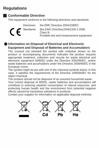
RegulationsConformable DirectiveThis equipment conforms to the following directives and standards:
Information on Disposal of Electrical and Electronic Equipment and Disposal of Batteries and AccumulatorsThe crossed out wheeled bin symbol with underbar shown on theproduct or accompanying documents indicates the product requiresappropriate treatment, collection and recycle for waste electrical andelectronic equipment (WEEE) under the Directive 2002/96/EC, and/orwaste batteries and accumulators under the Directive 2006/66/EC in theEuropean Union. The symbol might be put with one of the chemical symbols below. In thiscase, it satisfies the requirements of the Directive 2006/66/EC for theobject chemical. This product should not be disposed of as unsorted household waste.Your correct disposal of WEEE, waste batteries and accumulators willcontribute to reducing wasteful consumption of natural resources, andprotecting human health and the environment from potential negativeeffects caused by hazardous substance in products.Contact your supplier for information on applicable disposal methods.
Directives: the EMC Directive 2004/108/ECStandards: [the EMC Directive] EN61326-1:2006
Class B, Portable test and measurement equipment
FCC RulesAny changes or modifications not expressly approved by the partyresponsible for compliance shall void the user's authority to operate theequipment.
WARNINGThis equipment has been tested and found to comply with the limits for aClass A digital device, pursuant to part 15 of the FCC Rules. These limitsare designed to provide reasonable protection against harmfulinterference when the equipment is operated in a commercialenvironment. This equipment generates, uses, and can radiate radiofrequency energy and, if not installed and used in accordance with theinstruction manual, may cause harmful interference to radiocommunications. Operation of this equipment in a residential area is likely to causeharmful interference in which case the user will be required to correct theinterference at his own expense.
Korea Certification
Taiwan Battery Recycling Mark
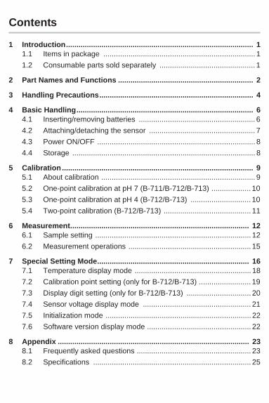
Contents
1 Introduction.......................................................................................... 11.1 Items in package ......................................................................... 11.2 Consumable parts sold separately .............................................. 1
2 Part Names and Functions ................................................................. 2
3 Handling Precautions.......................................................................... 4
4 Basic Handling..................................................................................... 64.1 Inserting/removing batteries ........................................................ 64.2 Attaching/detaching the sensor ................................................... 74.3 Power ON/OFF ............................................................................ 84.4 Storage ........................................................................................ 8
5 Calibration ............................................................................................ 95.1 About calibration .......................................................................... 95.2 One-point calibration at pH 7 (B-711/B-712/B-713) ................... 105.3 One-point calibration at pH 4 (B-712/B-713) ............................. 105.4 Two-point calibration (B-712/B-713) .......................................... 11
6 Measurement...................................................................................... 126.1 Sample setting ........................................................................... 126.2 Measurement operations ........................................................... 15
7 Special Setting Mode......................................................................... 167.1 Temperature display mode ........................................................ 187.2 Calibration point setting (only for B-712/B-713) ......................... 197.3 Display digit setting (only for B-712/B-713) ............................... 207.4 Sensor voltage display mode .................................................... 217.5 Initialization mode ...................................................................... 227.6 Software version display mode .................................................. 22
8 Appendix ............................................................................................ 238.1 Frequently asked questions ....................................................... 238.2 Specifications ............................................................................ 25


1
1 IntroductionThe COMPACT pH METER B-711, B-712, and B-713 incorporate HORIBAoriginal flat sensor and enables accurate pH measurement from a singledrop of a sample.
1.1 Items in package
1.2 Consumable parts sold separately
Meter model B-711 B-712 B-713
Sensor S010 1 1 1
Meter
B-711 1 - -
B-712 - 1 -
B-713 - - 1
Storage case 1 1 1
Batteries CR2032 2 2 2
Standard solutions
pH 4 (pH 4.01) - 1 1
pH 7 (pH 6.86) 1 1 -
pH 7 (pH 7.00) - - 1
Pipette 1 1 1
Sampling sheet B 5 sheets 1 1 1
Instruction manual Common to all model
1 1 1
Quick-start manual 1 1 1
Part No. Name Type Application
3200459834 Sensor S010, pH B-711, B-712, B-713
3200457725 Standard solutions
Y017, pH 6.86 B-711, B-712 (pH 7)
3200457726 Y014, pH 4.01 B-712, B-713 (pH 4)
3200459736 Sampling sheet holder cover Y048 B-711, B-712, B-713, B-721, B-722,
B-731, B-741, B-742, B-743, B-751
3200053858 Sampling sheet B
Y046, 100 sheet-pack
B-711, B-712, B-713, B-721, B-722, B-731, B-741, B-742, B-743, B-751

2
2 Part Names and Functions
No. Name Description
1 Flat sensorPlace a sample on this sensor. This sensor consists of a liquid junction (A) and glass membrane (B). Both A and B must be covered with the sample.
2 Light shield coverShields the sensor from light, which affects the sensor. Close the light shield cover before starting measurement. If using the sampling sheet holder cover (refer to page 14), shield the flat sensor from light with an alternative.
3 Lithium batteries CR2032 ( 2)
4 MEAS switchSwitches the calibration mode to the measurement mode, activates/deactivates the reading locking function in the measurement mode, and starts/applies settings in the special setting mode.
5 ON/OFF switch Turns ON/OFF the meter.
6 CAL switch Starts calibration, and switches items/settings in the special setting mode.
7 Waterproof gasket Makes the meter waterproof.
AB
1
2
3
4 5
6
7
8
910
11
12
13
14 15

3
8 Strap eyelet A strap can be attached here.
9 MEAS iconBlinks until the measured value is stabilized, and lights steadily when the measured value is settled, while the reading locking function is active.
10 CAL icon Blinks during calibration, and lights steadily when calibration is finished.
11 Battery alarm icon Lights up when the batteries are low and need to be changed.
12 Temperature alarm icon
Blinks when the measuring environment temperature does not meet the specified operating temperature (5 C to 40 C).
13 Stability icon Lights up when the measured value is stabilized.
14 Measured value display Displays a measured, set, or status value.
15 Measurement unit display
A unit symbol lights up corresponding to the value displayed on the measured value display (14). But no unit symbol lights up for a pH value.
No. Name Description

4
3 Handling PrecautionsMeter and sensor
The sensor is a consumable part. If it becomes damaged or itsperformance deteriorates, replace it with a new one (the sensor can notbe repaired).Do not swing the meter and sensor by holding a strap.To ensure the waterproof performance, confirm the followings whenattaching the sensor. - The waterproofing gasket is clean and undamaged.- The waterproofing gasket is seated properly in the groove with no twisting or warping.- The meter and sensor are not deformed.Neither the meter nor sensor is waterproof by itself.The sensor must be securely mounted on the meterbefore use.Do not drop the meter or apply excessive force to it.
Do not leave the meter in areas of direct sunlight or high temperature/humidity.Do not clean the meter with organic solvents.
The flat sensor is made of thin glass. Take care not to break it. If it isdamaged, remove the sensor avoiding injury and dispose of it in aplastic bag.

5
Do not measure samples such as the following, since they maydamage the sensor or shorten its life: Organic solvents, oils, adhesives,cement, alcohols, concentrated acid (0 pH to 2 pH), concentratedalkaline (12 pH to 14 pH) or surfactants.When using this product for the first time or after several days ofdisuse, the sensor may be slow to respond. In this case, add somedrops of pH 7 standard solution to the sensor and wait a few hoursbefore use (there is no need to turn the power ON).For some sample types (such as pure water), the measured value maybe unstable.A small amount of liquid or white powder may appear on the liquidjunction of the flat sensor. The appearance of this powder or solution isnormal. Simply rinse it off with water before use.
BatteryKeep batteries out of reach of children. If someone accidentallyswallows a battery, call a doctor immediately. Do not throw batteries in fire.Do not attempt to recharge batteries.The provided batteries are intended for use in operation checking,therefore their service life may be short.The battery alarm icon lights up when the battery voltage is low.Replace the batteries when the battery alarm icon lights up. The meterpower may not be turned ON/OFF when the battery voltage is low.Replace the 2 batteries at the same time.
OthersWash off any calibration fluid that comes into contact with hands orother exposed skin. If fluid gets in eyes, rinse them immediately andsee a doctor.

6
4 Basic Handling4.1 Inserting/removing batteries
NoteTurn OFF the meter before inserting/removing batteries.Always replace both batteries at once. Do not use old and newbatteries together.
Inserting the batteries1. Slide both batteries into the
battery case as shown.Be sure to use two CR2032 batteries, and put them with the plus sides (+) upwards.
Removing the batteries1. Use a ball-point pen or other tool to pry
the batteries out from the clips asshown.
Battery Battery
clip

7
4.2 Attaching/detaching the sensorNote
Turn OFF the meter before attaching/detaching the sensor.If the meter is turned ON with the sensor detached, the batteryalarm may light up. In this case, turn OFF the meter and attach thesensor, and then turn ON the meter again.
NoteMake sure that the sensor tongue is outside the meter case.If the tongue is inserted between the case and the connector ofthe meter, it may damage the connector.
When removing the sensor, do not let any water get inside themeter. If some moisture remains on the waterproof gasket, wipe itoff carefully.
Attaching the sensor1. Confirm that the waterproofing gasket is
clean and undamaged.2. Slide the sensor onto the meter so that
catch "A" on the back of the meter fits into hole "a" on the sensor tongue as shown. Note
Be careful not to twist the waterproof gasket.
Detaching the sensor1. Lift the sensor tongue tip and slide the
sensor a little away from the meter. 2. Pull out the sensor all the way from the
meter.
a A
Waterproofgasket
Sensor tongue Meter
Connector Meter
Good
SensorMeter
Sensor
Wrong

8
4.3 Power ON/OFF
4.4 Storage1. Clean the sensor with tap water and remove moisture on the sen-
sor and meter with soft cloth or paper.
NoteDo not push the flat sensor strongly. It may damage the sensor.
2. Close the light shield cover and the slide cap, then store the meter.
Power ON1. Press and hold the ON/OFF switch for
over 2 seconds.The power is turned ON, and the meter model number is displayed on the LCD.
Power OFF1. Press and hold the ON/OFF switch for
over 2 seconds.The power is turned OFF.

9
5 Calibration5.1 About calibration
Calibration pointsThe available calibration points depend on the meter models.
One-point calibration at pH 7: B-711, B-712, B-713One-point calibration at pH 4: B-712, B-713Two-point calibration: B-712, B-713
“One-point calibration at pH 7” is set by default.Refer to the instructions on page 19 for switching the calibration points (forB-712 and B-713 only). The calibration point setting and calibration result are saved after the meteris turned OFF.
TipFor B-712 and B-713, two-point calibration is recommended especiallyif sample pH is outside 1 pH from the pH of the standard solution.
Precautions for calibrationIf remains blinking and Err (error display)appears, the calibration is failed. Check that the standard solution pH is correct,and perform calibration again after cleaning thesensor well.If the calibration is failed using correct standard solution(s), the sensormay be deteriorated. Replace the sensor with new one (part No.:3200459834).In two-point calibration, confirm that the calibration operations arecompleted respectively for pH 7 and pH 4. The calibration operation for pH 4 can not start until the calibration forpH 7 is completed, and the whole calibration sequence is not com-pleted until the calibration for pH 4.

10
5.2 One-point calibration at pH 7 (B-711/B-712/B-713)
5.3 One-point calibration at pH 4 (B-712/B-713)
1. (For B-712 and B-713 only) Set “One-point calibration at pH 7” (refer to page 19).
2. Open the light shield cover and put some drops of the pH 7 standard solution on the flat sensor to cover the entire flat sensor. Washing the sensor with the standard solution beforehand may provide more accurate calibration.
3. Close the light shield cover and press the CAL switch for over 2 seconds.
and blink and the calibration value is displayed.After the calibration is completed, and
stop blinking and light steadily. 4. Clean the sensor with tap water and
remove moisture.5. Press the MEAS switch for 0.5 seconds to
enter the measurement mode and prepare for measurement.
1. Set “One-point calibration at pH 4” (refer to page 19).2. Open the light shield cover and put some drops
of the pH 4 standard solution on the flat sensor to cover the entire flat sensor. Washing the sensor with the standard solution beforehand may provide more accurate calibration.
3. Close the light shield cover and press the CAL switch for over 2 seconds.
and blink and the calibration value is displayed.After the calibration is completed, and
stop blinking and light steadily. 4. Clean the sensor with tap water and
remove moisture. 5. Press the MEAS switch for 0.5 seconds to
enter the measurement mode and prepare for measurement.
Light shield cover
Light shield cover

11
5.4 Two-point calibration (B-712/B-713)
8. Press the MEAS switch for 0.5 seconds to enter the measurement mode and prepare for measurement.
1. Set “Two-point calibration” (refer to page 19).2. Open the light shield cover and put some drops
of the pH 7 standard solution on the flat sensor to cover the entire flat sensor. Washing the sensor with the standard solution beforehand may provide more accurate calibration.
3. Close the light shield cover and press the CAL switch for over 2 seconds.
and blink and the calibration value is displayed.After the calibration is completed, and
stop blinking and light steadily.
4. After the calibration for pH 7 is completed, open the light shield cover to remove the pH 7 standard solution and remove mois-ture on the sensor.
5. Put some drops of the pH 4 standard solution on the flat sensor to cover the entire flat sensor. Washing the sensor with the standard solution beforehand may provide more accurate calibration.
6. Close the light shield cover and press the CAL switch for over 2 seconds.
and blink and the calibration value is displayed.After the calibration is completed, and
stop blinking and light steadily.
7. Clean the sensor with tap water and remove moisture.
Light shield cover
Light shield cover

12
6 Measurement6.1 Sample settingThe following 4-type sampling setting methods are available.
Drop: for a small-amount sampleImmersion: for a large-amount sampleScooping: for sampling a part of a sampleSampling sheet: for a sample containing tiny particles
NoteAlthough this product is waterproof, avoid immersing it completely.If the product is accidentally dropped into water, take it out of waterand remove the moisture on it.
Tip
Drop1. Open the light shield cover and put some drops of sample on the
flat sensor to cover the entire flat sensor. 2. Close the light shield cover.
Try to use the provided sampling sheet Bfor a minute sample.Using this sheet, the entire flat sensor canbe covered with only 50 L to 100 Lsample.
Note that a reaction between asample and the sampling sheet Bmay affect the measured value.Handle the sampling sheet B with tweezers to minimize possiblecontamination. Make sure to close the light shield cover during measurement tominimize possible sample evaporation.
Light shield cover
13
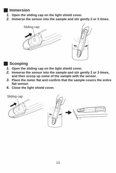
Immersion1. Open the sliding cap on the light shield cover.2. Immerse the sensor into the sample and stir gently 2 or 3 times.
Scooping1. Open the sliding cap on the light shield cover.2. Immerse the sensor into the sample and stir gently 2 or 3 times,
and then scoop up some of the sample with the sensor.3. Place the meter flat and confirm that the sample covers the entire
flat sensor.4. Close the light shield cover.
Sliding cap
Sliding cap

14
Sampling sheetIf tiny particles are contained in a sample, such as an extract from soil, theparticles influence measurement results. Use the sampling sheet holdercover (part No. 3200459736) and sampling sheet B (part No. 3200053858)sold separately to counteract the influence.
NoteThe sampling sheet holder cover does not shield the sensor from light,which affects the sensor. When using the sampling sheet holder cover,shield the flat sensor from light with an alternative.
1. Replace the light shield cover with the sampling sheet holdercover.
2. Put a piece of sampling sheet B on the flat sensor and close the sampling sheet holder cover.
3. Put 4 or 5 drops of sample on the sampling sheet B.
Light shield cover
Sampling sheet holder cover
Sampling sheet B

15
6.2 Measurement operations
NoteIf a measurement result is out of the specified measurementrange, the displayed measured value blinks. When using the reading locking function, deactivate the functionbefore starting every measurement.
Without using the reading locking function1. Confirm that the meter is in the measurement mode, and set a
sample on the sensor.2. Read the displayed value when
appears.
With using the reading locking function1. Confirm that the meter is in the measurement mode, and set a
sample on the sensor.2. After appears, press the MEAS switch
for 0.5 seconds.The reading locking function is activated.
blinks until the measured value is stabi-lized.When the measured value is settled, stops blinking and the displayed value is locked with and lighting steadily.
3. Read the displayed value.4. Press the MEAS switch for 0.5 seconds.
The reading locking function is deactivated and disappears.
16
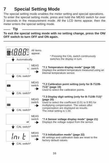
7 Special Setting ModeThe special setting mode enables the meter setting and special operations.To enter the special setting mode, press and hold the MEAS switch for over3 seconds in the measurement mode. All the LCD items appear, then themeter enters the special setting mode.
TipTo exit the special setting mode with no setting change, press the ON/OFF switch to turn OFF and ON again.
* Pressing the CAL switch continuously switches the display in turn.
"7.1 Temperature display mode" (page 18)Displays the ambient temperature measured using an internal temperature sensor.
"7.2 Calibration point setting (only for B-712/B-713)" (page 19)Used to select the calibration points.
"7.3 Display digit setting (only for B-712/B-713)" (page 20)Used to select the coefficient (0.01 to 9.90) for multiplying compensation. The values after compensation are displayed as results. The initial setting is 1.00.
"7.4 Sensor voltage display mode" (page 21)Displays the voltage output from the sensor.
"7.5 Initialization mode" (page 22)All settings and calibration data are reset to the factory default values.
Automatically
All items appear.
CAL switch*
MEASswitch
CAL switch*
MEASswitch
CAL switch*
MEASswitch
CAL switch*
MEASswitch
CAL switch*
MEASswitch

17
"7.6 Software version display mode" (page 22)The current software version is displayed.
Returns to the display for temperature display mode.CAL switch*
18
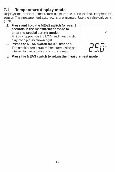
7.1 Temperature display modeDisplays the ambient temperature measured with the internal temperaturesensor. The measurement accuracy is unwarranted. Use the value only as aguide.
1. Press and hold the MEAS switch for over 3 seconds in the measurement mode to enter the special setting mode.All items appear on the LCD, and then the dis-play changes as shown right.
2. Press the MEAS switch for 0.5 seconds.The ambient temperature measured using an internal temperature sensor is displayed.
3. Press the MEAS switch to return the measurement mode.

19
7.2 Calibration point setting (only for B-712/B-713)Used to select the calibration points.
4. Press the CAL switch for 0.5 seconds to change the setting.Pressing the CAL switch continuously switches the display in turn.
5. Press the MEAS switch to apply the setting.The measurement mode is returned.
1. Press and hold the MEAS switch for over 3 seconds in the measurement mode to enter the special setting mode.All items appear on the LCD, and then the dis-play changes as shown right.
2. Press the CAL switch until appears.
3. Press the MEAS switch for 0.5 seconds.The current setting is displayed.
One-point calibration
Press the CAL switch
Press the CAL switchfor 0.5 seconds.
Press the CAL switchfor 0.5 seconds.
Two-point calibration
for 0.5 seconds.
at pH 4
One-point calibration at pH 7

20
7.3 Display digit setting (only for B-712/B-713)Used to select the display digit (One or two decimal places) for measuredvalue. The initial setting is one decimal place.
4. Press the CAL switch for 0.5 seconds to change the setting.
5. Press the MEAS switch to apply the setting.The measurement mode is returned.
1. Press and hold the MEAS switch for over 3 seconds in the measurement mode to enter the special setting mode.All items appear on the LCD, and then the dis-play changes as shown right.
2. Press the CAL switch until appears.
3. Press the MEAS switch for 0.5 seconds.The current setting is displayed.
One decimal place Press the CAL switch Two decimal placesfor 0.5 seconds.
21
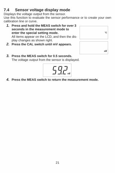
7.4 Sensor voltage display modeDisplays the voltage output from the sensor.Use this function to evaluate the sensor performance or to create your owncalibration line or curve.
3. Press the MEAS switch for 0.5 seconds.The voltage output from the sensor is displayed.
4. Press the MEAS switch to return the measurement mode.
1. Press and hold the MEAS switch for over 3 seconds in the measurement mode to enter the special setting mode.All items appear on the LCD, and then the dis-play changes as shown right.
2. Press the CAL switch until mV appears.

22
7.5 Initialization modeAll settings and all calibration data are reset to the factory default values.
7.6 Software version display modeThe current software version is displayed.This information may be asked for depending on your inquiry.
1. Press and hold the MEAS switch for over 3 seconds in the measurement mode to enter the special setting mode.All items appear on the LCD, and then the dis-play changes as shown right.
2. Press the CAL switch until Init appears.
3. Press the MEAS switch for 0.5 seconds. appears.
4. Press the CAL switch for over 2 seconds.All settings and all calibration data are reset to the factory default values.When initialization is completed, End and appear.
5. Press the ON/OFF switch to turn OFF and ON again.
1. Press and hold the MEAS switch for over 3 seconds in the measurement mode to enter the special setting mode.All items appear on the LCD, and then the dis-play changes as shown right.
2. Press the CAL switch until Init appears.
3. Press the CAL switch for 0.5 seconds.The software version is displayed.

23
8 Appendix8.1 Frequently asked questions
Question Answer
How long is the sensor's service life?
It depends on measurement samples and conditions.It should be approx. 1500 measurements for typical samples.Note that sensor deterioration and failure are not included in the warranty.
How can I check the sensor's condition?
For B-712 and B-713, perform two-point calibration. If calibration error occurs, the sensor is deteriorated. Replace the sensor.For B-711, measure the pH 4.01 standard solution (part No. 3200457726) sold seperately after calibration, and check how much the measured pH value drifts from the specified pH. if the measured value drifts, the sensor is deteriorated. Replace the sensor.
Are there any helpful tips or precautions to be aware for measurement?
Use the light shield cover to avoid direct sunlight during measurement because the sensor is affected by light.
When the sample amount is enough, washing the sensor twice or so with the sample allows more accurate measurement.
Residue between the light shield cover and flat sensor pre-vents accurate measurement. Before measurement of the next sample, clean the sensor with tap water and remove moisture.
Can I measure high- or low-temperature samples?
This product can not measure a sample with a temperature outside the meter's operating temperature range (5 C to 40 C).The difference between the sample temperature and ambient temperature increases the measurement error. Perform mea-surement after the sample reaches the ambient temperature.
The measured value does not change after changing the sample.
If lights steadily, the measured value is locked.Press the MEAS switch to unlock the value. If the value does not change after unlocking, the sensor may be damaged. Replace the sensor.
“0.0” blinks in pH measurement.
The measured pH may be out of the specified measurement range (2 pH to12 pH). Measure a standard solution to check, and if “0.0” blinks even then, replace the sensor.
The temperature alarm icon blinks during measurement.
The measuring environment temperature may not meet the specified operating temperature (5 C to 40 C).When the environment temperature is within the specified range and the alarm icon blinks, replace the sensor.

24
The power is not turned ON.
Check that the batteries are inserted properly. If the batteries are low, replace them both with new ones at the same time.
Er1 is displayed right after power ON.
The internal IC in the meter may defect.After Er1 is displayed, the meter enters the initialization mode automatically and Init and appear. Press the CAL switch for over 2 seconds to execute initialization, and then turn OFF and ON again (refer to page 22).If Er1 is still displayed after the initialization, the internal IC in the meter defects. Replace the product with new one (the meter can not be repaired).
Er2 is displayed right after power ON.
The internal IC in the meter defects. Replace the product with new one (the meter can not be repaired).
Er3 is displayed right after power ON.
The internal IC in the meter defects. Replace the product with new one (the meter can not be repaired).
How can I return all the settings of the special setting mode to the default settings?
Perform initialization (refer to page 22).
Question Answer

25
8.2 SpecificationsModel B-711 B-712 B-713 (US only)
Measurement principle Glass electrode method
Minimum sample volume 0.1 mL or more*1
Measurement range pH 2 pH to 12 pH
Display range 0 pH to14 pH*2
Resolution (valid digits) 0.1 pH 0.1 pH or 0.01 pH (selectable)
Calibration One-point Two-point*3
Accuracy ±0.1 pH*4
Display Custom (monochrome) digital LCD
Operating temperature/
humidity
5 C to 40 C, 85% or less in relative humidity (no condensation)
Power CR2032 batteries ( 2)
Battery life Approx. 400 hours in continuous use
Main materials ABS epoxy
Outer dimensions/mass
164 mm × 29 mm × 20 mm (excluding projections), Approx. 50 g (meter only, without batteries)
Main functions Temperature compensation, waterproof*5, reading locking, automatic power OFF
*1 0.05 mL or more if the sampling sheet B is used.*2 When the measured value is out of the measurement range, the displayed
value blinks. It should be used only as a guide.*3 Selectable between one-point and two-point calibrations.*4 Repeatability in measurement of a standard solution after calibration using the
same standard solution*5 IP67: no failure when immersed in water at a depth or 1 meter for 30 minutes.
But the product can not be used underwater.

2 Miyanohigashi, Kisshoin Minami-ku, Kyoto 601-8510 Japan
http://www.horiba.com