Embed Size (px)
Citation preview

www.safdrives.comemail: [email protected]
(Replies given within 24 hours)
18 Neville Street, Unit CNew Hamburg, ON N3A 4G7
Tel: 519-662-6489Fax: 1-866-280-5247
Installation & Operating Procedures
FS2 and FS4 Field Regulator

FS2 / FS4 SERIES
FIELD REGULATOR
September 2011 File: FS2 / FS4 MANUAL

FS2/4 Field Regulator
Page 2

FS2/4 Field Regulator
FOR YOUR SAFETY
Only qualified personnel should install this equipment, after first reading and understanding all the information in this manual. All instructions should be strictly adhered to. The user should consult SAF Drives Inc. or a SAF supplier for clarification of the contents of this manual should any doubt or questions arise.
The installation of this equipment must be conducted in accordance with all national, regional and local electrical codes.
All drawings and technical representations included in this manual are for typical installations and should not in any way be considered for specific applications or modifications. Consult SAF Drives for supplemental instructions.
SAF Drives Inc. accepts no liability for any consequences resulting from inappropriate, negligent or incorrect installation, application or adjustment of this equipment.
The contents of this manual are believed to be correct at the time of printing. In following with our commitment to the ongoing development and improvement of our products SAF Drives Inc. reserves the right to change the specification of this product and/or the content of this instruction manual without notice.
Page 3
FS2/4 Field Regulator
Page 4
FS2/4 Field Regulator
Table of Contents 1 INTRODUCTION TO FIELD REGULATORS................................................ 7
1.1 DC MOTOR FUNDAMENTALS........................................................... 7
1.2 SPILL-OVER ....................................................................................... 8
1.3 WHY USE A FIELD REGULATOR? ................................................... 8
2 FIELD REGULATOR APPLICATIONS......................................................... 9
2.1 GENERAL ........................................................................................... 9
2.2 TORQUE ............................................................................................. 9
2.3 CONSTANT HORSEPOWER (CEMF Winder / Unwinder)................ 9
2.4 VOLTAGE (Two Motors in Series on a Common Supply) .............. 9
2.5 SPEED REGULATION ...................................................................... 10
2.6 MOTOR SPEED IN FIELD RANGE................................................... 10
3 FS2 AND FS4 CIRCUIT DESCRIPTION .................................................... 11
3.1 POWER SUPPLY.............................................................................. 11
3.2 DIGITAL PHASE LOCKED LOOP.................................................... 11
3.3 FS2 AND FS4 CURRENT LOOP REGULATOR............................... 12
3.4 AIR - GAP FLUX COMPENSATION ................................................. 13
3.5 THYRISTOR GATE PULSE BURST GENERATOR ......................... 13
3.6 ARMATURE VOLTAGE SPILL-OVER CONTROL........................... 13
3.7 RESISTIVE ARMATURE VOLTAGE ISOLATOR............................. 14
3.8 FIELD LOSS PROTECTION ............................................................. 15
3.9 FIELD ECONOMY............................................................................. 15
3.10 IR COMPENSATION....................................................................... 15
4 CHOOSING THE CORRECT FIELD REGULATOR................................... 17
4.1 FS2 FIELD REGULATOR ................................................................. 18
4.2 FS4 FIELD REGULATOR ................................................................. 18
4.3 FS2-A FIELD REGULATOR ............................................................. 19
4.4 FS4-A FIELD REGULATOR ............................................................. 19
4.5 FS2 / FS4 BLOCK DIAGRAM WITH SPILL-OVER .......................... 19
Page 5
FS2/4 Field Regulator
Page 6
5 SPECIFICATIONS ...................................................................................... 22
5.1 POWER RATING............................................................................... 22
5.2 MAXIMUM RATINGS ........................................................................ 22
5.3 SERVICE CONDITIONS.................................................................... 22
5.4 MOUNTING DIMENSIONS................................................................ 23
6 CARD FUNCTIONS.................................................................................... 25
6.1 ANNUNCIATION ............................................................................... 25
6.2 ADJUSTMENTS................................................................................ 25
6.3 LINK SELECTION............................................................................. 26
6.4 PUSHBUTTON AND SWITCHES ..................................................... 26
6.5 TERMINALS...................................................................................... 27
7 START-UP AND OPERATING ADJUSTMENTS ....................................... 29
7.1 FIELD REGULATOR SET-UP........................................................... 29
8 TYPICAL CONNECTIONS ......................................................................... 32
8.1 FS2-12-2/4 CONNECTED AT 240VAC ............................................. 32
8.2 FS2A-12-2/4 CONNECTED AT 240VAC .......................................... 33
8.3 FS4-12-2/4 CONNECTED AT 240VAC ............................................. 34
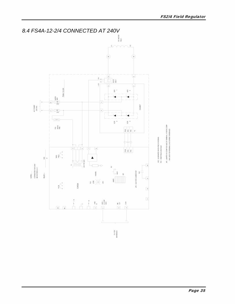
8.4 FS4A-12-2/4 CONNECTED AT 240V................................................ 35
9 SPARE PARTS........................................................................................... 36

1 INTRODUCTION TO FIELD REGULATORS 1.1 DC MOTOR FUNDAMENTALS
A DC motor operates as the result of the interaction of two magnetic fields, one produced by the armature winding and the second by the field winding or permanent magnet. These two fields are stationary in space and 90º apart. The DC motor brushes maintain the magnetic flux stationary in space when the motor rotates. The field winding could be connected in series with, or parallel to, the armature winding, or separately excited. The FS2/FS4 field regulators are designed to be used on separately excited motors. The vast usage of DC motors for variable speed applications is based on its control simplicity. A DC motor with constant field can be stated:
Torque is proportional to armature current, independent of speed and
Speed is proportional to armature voltage, independent of torque
In a more accurate analysis, the motor torque produced is directly proportional to the product of the armature magnetic flux and the field magnetic flux. These two fluxes are proportional to the armature and field current; however it is not a linear relation. For practical purposes the armature flux is considered linear with respect to the armature current, however this is not true for the field due to the fact that the field is normally utilized in the saturated region of the iron. This means:
Torque = k1 * Ia * øf k1 : Motor Constant
øf : : Field Flux Ia : Armature Current
The field of the motor is active in the production of torque and also determines the voltage internally generated in the motor. The internally generated voltage is called the counter electromotive force or CEMF.
CEMF = k2 * ω* øf ω : Motor Speed
k2 : Motor Constant
The armature voltage of a DC motor is equal to the CEMF plus the IR drop caused by the motor armature resistance.
Va = k * ω* øf + Ia * Ra Va : Armature Voltage
Ra : Armature Resistance
The ability to control torque directly permits excellent dynamic variable speed control for a wide range of applications. The use of a field regulator is helpful in achieving maximum performance.
FS2/4 Field Regulator
1.2 SPILL-OVER A DC motor can operate in two regions, constant torque and constant horsepower. A field regulator with spillover control will operate in both regions by maintaining full field up to rated armature voltage, then reducing the field to increase the motor speed.
1.2.1 CONSTANT TORQUE From rest to rated base speed the field is maintained at full flux, therefore the rated motor torque is available throughout this speed range. The motor horsepower available is directly proportional to the speed.
1.2.2 CONSTANT HORSEPOWER At base speed the voltage on the armature is at a maximum value and to increase speed the field must be reduced. At this point the horsepower has become constant but the torque capability reduces with speed.
1.3 WHY USE A FIELD REGULATOR? The field regulator is designed specifically to provide controlled DC current output for the highly inductive loads found in the motor field coils. The use of a regulator provides the following benefits:
♦Consistent field flux level independent of motor temperature changes ♦Allows overspeed with maximum torque at the lower speed which minimizes the motor size on constant horsepower applications ♦Allows load sharing of motors that are tied to the same load or power supply ♦Provides ability to control torque (tension) and speed ♦Provides protection to the motor against overheating via field economy ♦Provides field loss detection to avoid overspeed
Page 8
FS2/4 Field Regulator
2 FIELD REGULATOR APPLICATIONS 2.1 GENERAL
Through proper application of the field regulator for control of a DC motor it is possible to regulate all the motor parameters by controlling the motor field flux thereby regulating the field ampere turns. The following field considerations should be made for various examples of DC Motor applications.
2.2 TORQUE The components of torque are armature current and motor field flux density. If the most critical parameter of the system is the torque output of the motor, changing either of these parameters will directly affect output torque. To control the torque by regulating the motor armature amperes the motor field amps must also be regulated to maintain a controlled torque output. If the motor amps are regulated and the field is supplied by a fixed voltage source the motor torque will vary as the field heats up. This can change the motor torque by as much as 20-30% depending on the field characteristics.
2.3 CONSTANT HORSEPOWER (CEMF WINDER / UNWINDER) Field control can be employed in an application where the motor is overhauled by the process and the horsepower must be regulated to maintain a product tension. On a centre driven unwind for example; the material is pulled off the roll. Assuming a constant surface speed, as the roll diminishes the diameter reduces which would increase the core speed. If the motor is current regulated only and the speed is increased the motor volts would increase proportionally. To prevent this the motor field can be regulated by the FS2 to maintain the motor voltage proportional to line speed. With the current regulated and the voltage regulated, the output power is regulated resulting in constant horsepower.
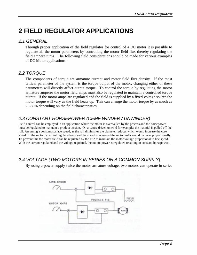
2.4 VOLTAGE (TWO MOTORS IN SERIES ON A COMMON SUPPLY) By using a power supply twice the motor armature voltage, two motors can operate in series
Page 9

FS2/4 Field Regulator
and basically share the voltage drop. If the load distribution is critical, the voltage on each motor can be regulated by the FS2 field regulator. If one motor needs to have more power the voltage across that motor can be regulated as a percentage of the other motor. Since both motors have the same current (through the armature) the work sharing is directly related to the voltage across each motor armature.
2.5 SPEED REGULATION More than one motor can operate from a common armature supply. When this is the case and the individual drives must be matched in speed regulation, it is necessary to use a field regulator to match the speeds. If a section is running slow the reference to the field regulator is reduced lowering the flux level causing armature current to increase and bring up the motor speed to match the motor CEMF to the common supply voltage. Using tachometer feedback the increase in speed will satisfy the regulator input. A speed feedback increase will cause the field regulator to turn on and slow the motor.
2.6 MOTOR SPEED IN FIELD RANGE This is the most common application for the FS2 field regulator. The motor is run as a speed regulator and the armature supply will satisfy the speed loop. Up to base speed the voltage regulator on the FS2 is saturated to supply base field amps. A spill over voltage is set on the FS2 and once the armature voltage reaches the spill-over level the voltage regulator comes into range and the field is weakened. As the speed increases the field current decreases thus regulating the armature voltage throughout the field weakening range. With this type of control a speed feedback device must be used.
Page 10

FS2/4 Field Regulator
3 FS2 AND FS4 CIRCUIT DESCRIPTION 3.1 POWER SUPPLY
The power supply is delivered via 240/480 VAC, 50/60 Hz transformed to a secondary signal of 36 VAC center-tapped. The primary voltage range is changed via wire links on a four screw terminal strip marked AC. If another voltage other than 240 or 480 VAC is used, a transformation to either voltage is necessary. The transformer also supplies a mains synchronizing signal to the phase locked loop circuitry. The secondary voltage is full-wave rectified to provide an unregulated +24 and -24 VDC. Unregulated +24 VDC is used to supply the thyristor gate pulse transformers and relay K2. The two unregulated 24 VDC supplies are series regulated to provide +15 and -15 VDC supplies. The +15 VDC supply is further series regulated to provide +5 VDC for all digital I.C. requirements. The +5 VDC is not available for external use. The +15 and -15 VDC supplies are available for external use on terminal strip TB4. A maximum of 50 milliamperes can be used externally. The maximum current used externally is the summation of the current from both +15 and -15 VDC supplies.
3.2 DIGITAL PHASE LOCKED LOOP The phase locked loop is controlled by IC6, a 74HC4046 integrated circuit. IC6 provides a voltage controlled oscillator and uses phase comparator #1, an Exclusive-OR gate. The mains synchronizing signal from the control transformer is converted by IC3-A to a square-wave with HCMOS logic levels. This signal is input to IC6 pin 14 as a phase comparator reference and as data to a D-type flip-flop, IC8-A. The voltage controlled oscillator operates at 512 times the mains frequency, 25.6 KHz with 50 Hz mains and 30.72 KHz with 60 Hz mains. The voltage controlled oscillator center frequency is 28.16 KHz, or equivalent to a 55 Hz mains frequency. The voltage controlled oscillator frequency is controlled by an operational amplifier, IC3-B, operating as an inverting proportional-integral loop. The operational amplifier reference level is -2.5 VDC and the feedback signal is the phase comparator output from IC6. IC6 phase comparator #1 operates with +90o displacement. At +90o displacement, phase comparator #1 outputs a 50% duty cycle square-wave at twice the mains frequency and has an average value of +2.5 VDC. When the phase locked loop is locked to the mains, the operational amplifier error is zero. The phase locked loop maintains the +90o displacement over a mains frequency range of 45 Hz to 65 Hz. No adjustments are necessary. Average lock time is 25 milliseconds after power is applied.
Page 11
FS2/4 Field Regulator
The voltage controlled oscillator output is VCOCLK. This is the clock frequency for an 8-bit binary down-counter. The 8-bit counter states are converted to an analog ramp by IC2, an 8-bit digital-to-analog converter. The most significant bit complement of the 8-bit counter is a clock to the D-type flip-flop, IC8-A, that has its data set by the square-wave mains signal. The D-type flip- flop, IC8-A, NOT-Q output is the phase feedback signal. This feedback is input to the 74HC4046 #1 phase comparator input.
3.3 FS2 AND FS4 CURRENT LOOP REGULATOR A 500:1 DC Current Transformer is used on the F + output of the DC bridge. A 25 Amp bridge will provide 125 milliamps of feedback at full output. The DC Current Transformer is powered by the ± 15 volt power supply from the CA526. The current transformer secondary lead is connected to terminals 1 or 2 of the 2-pole phoenix connector. Either terminal is appropriate as this signal is rectified by a full-wave diode bridge. Two of the diodes are 15 volt zeners to provide transient protection for the internal circuits. The output of the diode full-wave bridge has a 1000 ohm internal fixed burden resistor. Minimum current without an external burden resistor is 0.1 ampere and maximum is 1 ampere. To scale the signal for the current amplifier, a metal film, 1%, 0.6 watt burden resistor is required. Calibrate RBURDEN as follows: RBURDEN = 500 RBURDEN is the burden resistor IF IF is the desired field current i.e.: For 17 Amps RBURDEN is 500/17A= 29.4 ohms Voltage across the burden resistor is directly proportional to the output current. Full field output current is equal to 1.0 VDC across RB. The above equation assumes that MAX FIELD, RV1, is set at 45%. RV1 adjusts motor shunt field current for correct values to achieve proper DC motor armature voltage at motor base speed. MAX FIELD has a range of adjustment to permit motor shunt field current adjustment from approximately 25% to 200% of the IF value used for calculation in the above equation. Calibrated shunt field current feedback is output on Terminal 5 and is -1 VDC at motor base speed. Terminal 5 can be used as a buffered output to monitor shunt field current. Maximum current from this output is 5 milliamperes at -1 VDC. The current loop regulator, has fixed proportional-integral components and regulates shunt field time constants from 0.25 to 3.5 seconds without modification. Summing level into the current loop regulator is 1 milliampere at motor base speed, or maximum motor shunt field current. Shunt field current reference at maximum shunt field current is fixed at 1 milliampere through 15 kilo-ohms from +15 VDC. The current loop regulator output, is a phase angle reference. An op-amp compares the phase angle reference to the mains phase. If the phase angle reference is less than the mains phase
Page 12

FS2/4 Field Regulator
angle, the pulse burst generator is enabled. The pulse burst generator is enabled twice every mains cycle. Mains phase angle resolution is 0.703o electrical. The 8-bit counters are used twice per mains cycle for a total of 512 counts per cycle. 360o / 512 counts = 0.703125o
3.4 AIR - GAP FLUX COMPENSATION To provide air-gap flux compensation a proportional amplifier that modifies shunt field references into the current loop regulator is used. The gain characteristics of the op-amp vary inversely with its own output. A 2-point break approximation is used. The variable gain characteristic compensates for the non-linear relationship between shunt field ampere-turns and effective motor air-gap flux. In addition, the compensation aids in stabilizing the armature voltage regulating loop in the shunt field range. The output of the op-amp reduces shunt field current. An auxiliary input for shunt field control is provided on Terminal 4. Positive signals reduce shunt field current. Signals on Terminal 4 do not increase shunt field current above the value set by MAX FIELD, RV1, nor can shunt field current be decreased to less than the value set by MIN FIELD, RV3. Input impedance at Terminal 4 is 10 kilo-ohms. The minimum output from the op-amp is limited by MIN FIELD, RV3. RV3 prevents requests for excessive shunt field current reduction. RV3 also calibrates the LED bar display.
3.5 THYRISTOR GATE PULSE BURST GENERATOR The gate pulse burst generator uses the VCOCLK complement as a clock into a divide by four counter. The counter is gated to run by a phase angle comparator. When the counter runs, it provides a gate pulse train with mark/space ratios of 4 to 1. The gate pulses are 39 microseconds wide with 50 Hz mains and 32.5 microseconds wide with 60 Hz mains. The mark/space ratio permits the gate pulse transformers to be completely reset between pulses. Gate pulse trains are continuous from any firing angle to 180o.
3.6 ARMATURE VOLTAGE SPILL-OVER CONTROL Motor armature voltage is regulated by an op-amp. The op-amp compares motor armature voltage to a reference level set by the adjustment MAX ARM, RV4. No voltage regulation occurs until motor armature voltage exceeds the reference level. After the armature voltage reference level is exceeded, the op-amp provides an output that reduces motor shunt field current. Motor shunt field current is reduced until motor armature voltage agrees with the motor voltage reference. The op-amp regulates in a proportional band, approximately 6% of the armature voltage range (zero to rated nameplate voltage). The proportional band permits a smooth transition from the constant torque mode to the constant horsepower mode. Maximum
Page 13

FS2/4 Field Regulator
armature voltage is not attained until maximum speed is reached. Motor armature voltage increases slightly throughout the entire shunt field operation range. A negative absolute value signal proportional to motor armature is available at Terminal 3. This signal range is 0 to -5 VDC, directly proportional to armature voltage over the armature voltage range from zero to rated motor nameplate voltage.
3.7 RESISTIVE ARMATURE VOLTAGE ISOLATOR A resistive voltage isolator input is provided on a 2 position terminal strip marked ARM INP, terminals AA and BB. High voltage DC motor armature connections are made to these two points. Two voltage attenuation resistors (RAA and RBB) must be installed to calibrate the voltage isolator. The two resistors should be equal in resistance value. The signal must be directly connected to the motor armature through isolating devices. No interposing devices such as contactors, relays, or fuses may be connected in this signal path. This signal cannot be disconnected during emergency stopping or when using dynamic braking. The attenuated armature signal is fed to a voltage isolator, the output is converted to the negative absolute value. The output of the absolute value circuit is 0 to -5 VDC. Absolute value permits the isolator to be used in reversing applications. The voltage isolator is enabled with Molex JP1. Position AB (CA526) or Disable (CA526-1) disables the isolator and position BC (CA526) or Enable (CA526-1) enables the isolator. RAA = RBB = 2 x (Armature Voltage -90) in kilo-ohms
CAUTION FAILURE TO PROVIDE DIRECT SIGNAL PATH CONNECTIONS CAN
RESULT IN SEVERE PERSONAL INJURY, DC MOTOR DAMAGE, THYRISTOR FAILURE OR CONTACTOR DAMAGE!
Standard Armature Voltages: 1. 90 VDC = Two Jumpers 2. 180 VDC = Two 180K Resistors
Page 14
FS2/4 Field Regulator
3. 240 VDC = Two 300K Resistors 4. 360 VDC = Two 560K Resistors 5. 500 VDC = Two 820K Resistors
3.8 FIELD LOSS PROTECTION Motor operation in the constant horsepower range must be monitored to assure that shunt field excitation is not lost. A minimum level of shunt current can be monitored. FLCB, RV5, adjusts the level for shunt field loss faults. When shunt field current is less than the level set by RV5, relay K1 provides normally-open contacts on Terminals 9 and 10. The coil is energized when the shunt field current is present. The shunt field loss contacts must be connected into system fault monitoring logic to ensure DC motor shut down for shunt field loss faults. Shunt field loss faults are annunciated by LD2, marked FLOSS (CA526) or FIELD OK (CA526-1). FLOSS is extinguished for a fault and reset via PB1, RESET.
3.9 FIELD ECONOMY Shunt field economizing time is controlled by the AC mains frequency. Time is equivalent to:
4.27 minutes @ 60Hz 5.12 minutes @ 50Hz
Terminals 7 and 8 are used to start the economizing timer. With no input to these terminals, field economy will not take effect. Application of 120 VAC across terminals 7 and 8, via a N.C. auxiliary contact mounted on the main DC loop contactor, will start the timer when the main DC loop contactor de-energizes. Any operation, JOG or RUN, resets the timer and if no operation occurs before the timer counts out, the shunt field voltage is reduced. Shunt field economizing is controlled by Jumper JP2. Position DE (CA526-1 Enable) enables economizing and position EF (CA526-1 Disable) disables economizing. Shunt field economizing is annunciated by LD1. LD1 is illuminated when economizing is in effect. On a CA526-1 the field economy function can also be initiated with a closed dry contact between terminals 13 and 14. The CA526-1 also has the addition function of setting the field economy level between 25% and 45% of max field current using RV6.
3.10 IR COMPENSATION IR compensation in the field regulator is required on impact type of loads when the motor is in field weakening. If we review the motor equation
Page 15

FS2/4 Field Regulator
it's evident that the terminal voltage across the armature is the sum of the CEMF plus the IR drop.
R×I+××k=V AAFT ω
On impact load applications, the armature current changes from no load to full load very quickly. When this occurs the armature terminal voltage increases, causing the field regulator to further weaken the field, reducing the motor torque causing an additional increase in the armature current. This problem is solved if the field regulator maintains a constant back EMF, rather than constant armature terminal voltage. This is the purpose of IR comp. When IR is selected, a signal proportional to the armature current is added to the field current reference to compensate for any change in the armature current that may occur.
Page 16

FS2/4 Field Regulator
4 CHOOSING THE CORRECT FIELD REGULATOR SAF has provided four field regulator versions to serve a wide range of applications. These field regulators are listed below and are explained in more detail in the following pages.
FS2 : Provides stable field control in both motor operational regions, constant torque and constant horsepower. Utilizes a DC current transformer for feedback and uses two Silicon Controlled Rectifiers (SCR's) and two free wheeling diodes. FS2A : Provides stable current control based on an input reference. Utilizes a DC current transformer for feedback and uses two Silicon Controlled Rectifiers (SCR's) and two free wheeling diodes. FS4 : Similar to FS2 except uses four SCR's for control of the field in both increasing and decreasing directions. Utilizes a DC current transformer for feedback, has no free wheeling diode. FS4A : Similar to the FS2A other than the exception of the use of four SCR's for high response.
Page 17

FS2/4 Field Regulator
4.1 FS2 FIELD REGULATOR The FS2 field regulator is designed to provide stable field control in both motor operational regions, constant torque and constant horsepower. This bridge configuration uses 2 SCR's and 2 diodes to provide smooth operation without voltage transients. This allows forcing of the field in the increasing direction. For the field to decrease it must decay naturally through the free wheeling diodes at the L/R time constant of the field. This works well in most applications where high performance control or high acceleration rates are not required. A DC current transformer on the output of the regulator ensures the current feedback takes into account the current through the free wheeling diode. Armature voltage input is used to provide spill-over control. When the motor is run above base speed, the field spill-over control maintains the motor armature voltage at the rated value by reducing the field current. The spill-over control is a voltage PI regulator, where the reference is internally adjustable and is set to match the motor armature voltage. The feedback signal is the actual motor armature voltage. As the magnetic flux in the air-gap between the stator and the rotor is not exactly linear with field current, a variable gain circuit compensates for the non-linearity to improve stability. This function is called the air-gap flux compensation. Features of the FS2 include field loss, field economy, minimum field, IR and air-gap flux compensation.
4.2 FS4 FIELD REGULATOR The FS4 version of the field regulator is similar to the FS2 except the control uses 4 SCR's to add the ability to force the field in both the increasing and decreasing directions. This feature improves the response to weakening the field when the current reference is lowered. The loss
Page 18

FS2/4 Field Regulator
of the free wheeling diodes makes this regulator more difficult to stabilize at low current levels as the gate firing occurs at a high gain point in the sine wave. Features of the FS4 are the same as the FS2, field loss, field economy, minimum field, IR and air-gap flux compensation.
4.3 FS2-A FIELD REGULATOR This field regulator is similar to the FS2 except it is designed to provide a regulated current output that is proportional to a 0-(-10) Volts reference. The FS2-A regulator offers linear output current with respect to the input reference and does not have air-gap flux or IR compensation, minimum field control or spill-over. The FS2-A is useful for applications such as saturable reactors or where an adjustable fixed field is required.
4.4 FS4-A FIELD REGULATOR This is a 4 SCR version of the FS2-A for high response applications.
4.5 FS2 / FS4 BLOCK DIAGRAM WITH SPILL-OVER The FS2 and FS4 will provide spill-over control for regulation of the motor in field weakened range with an input available for IR compensation. There are pots to set the minimum field, maximum field, field loss level, maximum armature voltage for spill-over, and the stability of the current loop. An LED bar graph indicating output current and LED's for field loss and economy are provided for diagnostics.
Page 19

FS2/4 Field Regulator
FL
10
9
FLD CURRENTI AMPLIFIER
AUX
4
RV4
MAX ARM
+15V
ABC LINK
(AB=DISABLE SPILLOVER)
(EF=DIS. FLD. ECON.)
DEF LINK
MAX FLD.
120VAC
TIMER(4.5MIN)
RV2
V AMPLIFIER
3
F-
F+L1
L2
STAB
AA
BB
ARMATURE INPUT
CALIBRATION
VOLTAGE FBK.
AR
NEGATIVE ABSOLUTE
VOLTAGE FBK.
AUX.
INPUT
-15V
RV3
MIN
FLD.
AMPLIFIERFIELD
ECON.
1
2
CT
BURD
RESIST
RV1
MAX
MIN
FIELD
LEVEL
+15V
5
IFB OUT
FIELD LOSS
CONTACT
+15V
RV5
FLCB
FIELD
CALIBRATION
PRECISION
RECTIFIER
7
8
6
COMMON
FIELD BRIDGE
PHASE CONTROL
I/R COMP
JP2
JP1
JP3
MX
AUX
Page 20
FS2/4 Field Regulator
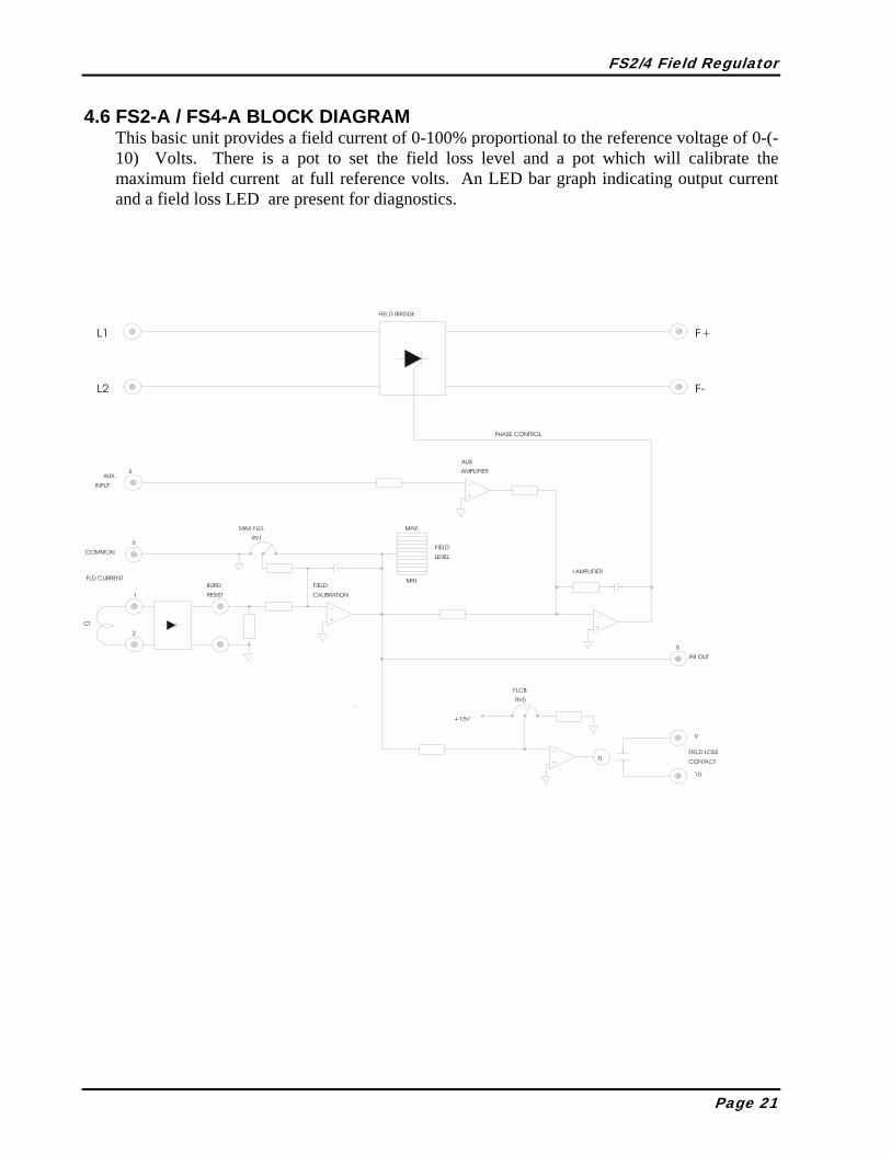
4.6 FS2-A / FS4-A BLOCK DIAGRAM This basic unit provides a field current of 0-100% proportional to the reference voltage of 0-(-10) Volts. There is a pot to set the field loss level and a pot which will calibrate the maximum field current at full reference volts. An LED bar graph indicating output current and a field loss LED are present for diagnostics.
Page 21
FS2/4 Field Regulator
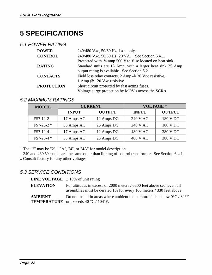
5 SPECIFICATIONS 5.1 POWER RATING
POWER 240/480 VAC, 50/60 Hz, 1ø supply. CONTROL 240/480 VAC, 50/60 Hz, 20 VA. See Section 6.4.1.
Protected with ¼ amp 500 VAC fuse located on heat sink. RATING Standard units are 15 Amp, with a larger heat sink 25 Amp
output rating is available. See Section 5.2. CONTACTS Field loss relay contacts, 2 Amp @ 30 VDC resistive,
1 Amp @ 120 VAC resistive. PROTECTION Short circuit protected by fast acting fuses.
Voltage surge protection by MOV's across the SCR's.
5.2 MAXIMUM RATINGS CURRENT VOLTAGE ‡ MODEL
INPUT OUTPUT INPUT OUTPUT FS?-12-2 † 17 Amps AC 12 Amps DC 240 V AC 180 V DC FS?-25-2 † 35 Amps AC 25 Amps DC 240 V AC 180 V DC FS?-12-4 † 17 Amps AC 12 Amps DC 480 V AC 380 V DC FS?-25-4 † 35 Amps AC 25 Amps DC 480 V AC 380 V DC
† The "?" may be "2", "2A", "4", or "4A" for model description. 240 and 480 VAC units are the same other than linking of control transformer. See Section 6.4.1. ‡ Consult factory for any other voltages.
5.3 SERVICE CONDITIONS LINE VOLTAGE ± 10% of unit rating ELEVATION For altitudes in excess of 2000 meters / 6600 feet above sea level, all
assemblies must be derated 1% for every 100 meters / 330 feet above. AMBIENT
TEMPERATURE Do not install in areas where ambient temperature falls below 0°C / 32°F or exceeds 40 °C / 104°F.
Page 22

FS2/4 Field Regulator
5.4 MOUNTING DIMENSIONS
5.4.1 MOUNTING FOR 12A UNIT
A
06"
11-3/4"
11-1/4"
11-3/4"
1/2"
0
6"1/2"0
- 4 HOLES, "A" DRILL 9/32 DIA.
F+ F- L1 L211-1/4"
5-1/2"
1/2"
1/2" 5-1/2"
A
A
A
4.5"
- ALL DIMENSIONS IN INCHES
Page 23

FS2/4 Field Regulator
5.4.2 MOUNTING FOR 25a UNIT A 25A unit consists of a 12A unit mounted on the heat sink as shown below.
9/25/96
-ALL DIMENSIONS IN INCHES.
-MATERIAL: Y100003 - 12" LONG, EXTRUDED ALUMINUM.
A
A A
0.625"
11.375"
12.0"
1.625"
6.625"
8.25"
2"
0.0"
A1.00
0.25 SLOT4 PLACES
(TYP.)
Page 24
FS2/4 Field Regulator
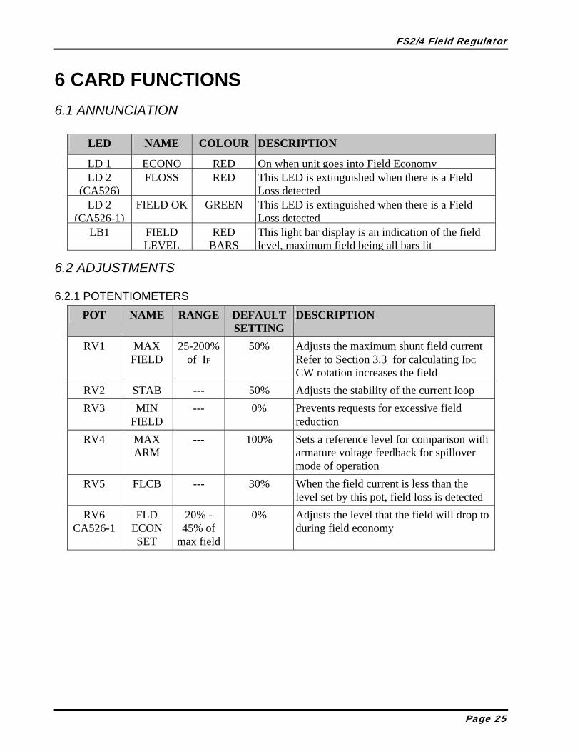
6 CARD FUNCTIONS 6.1 ANNUNCIATION
LED NAME COLOUR DESCRIPTION LD 1 ECONO RED On when unit goes into Field Economy LD 2
(CA526) FLOSS RED This LED is extinguished when there is a Field
Loss detected LD 2
(CA526-1) FIELD OK GREEN This LED is extinguished when there is a Field
Loss detected LB1 FIELD
LEVEL RED
BARSThis light bar display is an indication of the field level, maximum field being all bars lit
6.2 ADJUSTMENTS
6.2.1 POTENTIOMETERS POT NAME RANGE DEFAULT
SETTING DESCRIPTION
RV1 MAX FIELD
25-200% of IF
50% Adjusts the maximum shunt field current Refer to Section 3.3 for calculating IDC CW rotation increases the field
RV2 STAB --- 50% Adjusts the stability of the current loop RV3 MIN
FIELD --- 0% Prevents requests for excessive field
reduction RV4 MAX
ARM --- 100% Sets a reference level for comparison with
armature voltage feedback for spillover mode of operation
RV5 FLCB --- 30% When the field current is less than the level set by this pot, field loss is detected
RV6 CA526-1
FLD ECON SET
20% - 45% of
max field
0% Adjusts the level that the field will drop to during field economy
Page 25

FS2/4 Field Regulator
6.3 LINK SELECTION LINK POSITION DESCRIPTION AB or Disable At this position the voltage isolator is disabled, thus spill-over
disabled
JP1
BC or Enable Enables the armature voltage isolator and spill-over control Connects the negative absolute value to terminal 3
DE or Enable Enables shunt field economizing
JP2 EF or Disable Disables shunt field economizing
I/R COMP Terminal 4 used as input for I/R Comp (FS2 and FS4 only)
JP3 AUX This position enables Terminal 4 for an auxiliary current
Enable Enables automatic reset of a field loss when the field returns the unit will reset
JP4 CA526-1
Disable Disables automatic reset. You must use the reset button
6.4 PUSHBUTTON AND SWITCHES SWITCH NAME DESCRIPTION PB1 RESET Resets field loss when pressed if field current is above loss
level set by RV5, FLCB
Page 26

FS2/4 Field Regulator
6.5 TERMINALS
6.5.1 CUSTOMER TERMINAL TERMINAL NO. DESCRIPTION 1 CT connection
2 No connection
3 Negative absolute armature voltage feedback Output = 0 to -5 VDC
Auxiliary current reference if JP3 is in AUX position Positive inputs decrease shunt field current on FS2 or FS4
Input = 0 to +10 VDC, 0 VDC being maximum field Negative inputs increase field current on FS2A or FS4A
Input = 0 to (-10) VDC, -10 VDC being maximum field IR Compensation input if JP3 is in I/R COMP position
Positive inputs add to the field current reference
4
Impedance isolated, Input impedance = 10K ohms 5 Current feedback output which may be used to drive external
voltmeters calibrated to read shunt field current in amperes Output = 0 to -1 VDC, Max load = 5 milliamperes
6 Zero volt common for regulator circuits 7 Field economy input 120 VAC (Hot) 8 Field economy input 120 VAC (Neutral)
CA526 and CA526-1
9, 10 Normally open field loss relay contact 1.25 Amp @ 24 VDC resistive, 0.4 Amp @ 120 VAC resistive
11, 12 120VAC external reset input
CA526-1 only
13, 14 Dry contact field economy input. Closing this input will activate field economy after the allotted time
BURD RESIST
RB Mounting location for current calibrating burden resistor RB = 500 / IF
ARM Connected directly to armature leads through isolation Resistor (RAA) mounted between AA side and left AR terminal Resistor (RBB) mounted between BB side and right AR terminal
ARMATURE INPUT
AR Mounting location for resistors from ARM (See Section 3.7) RAA = RBB = 2 × (Armature Voltage - 90) in kilo-ohms
AC R, S 240/480 VAC control input dependent upon links R and S orientation critical to operation (See next page for linking of control transformer)
Page 27

FS2/4 Field Regulator
6.5.2 CONTROL VOLTAGE LINKS
480VAC
S
R
S
R
240VAC
6.5.3 TERMINALS FOR INTERNAL USE TERMINAL NAME DESCRIPTION PPWR Power supply source to gate firing FPTA Thyristor gate pulse connection
P2
FPTB Thyristor gate pulse connection -15 -15 VDC ± 0.75 VDC COM Zero volt common
TB4
15 +15 VDC ± 0.75 VDC 1 or 2 Current transformer secondary connection
CT -15, +15 Power supplies for LEM module current feedback
Page 28
FS2/4 Field Regulator
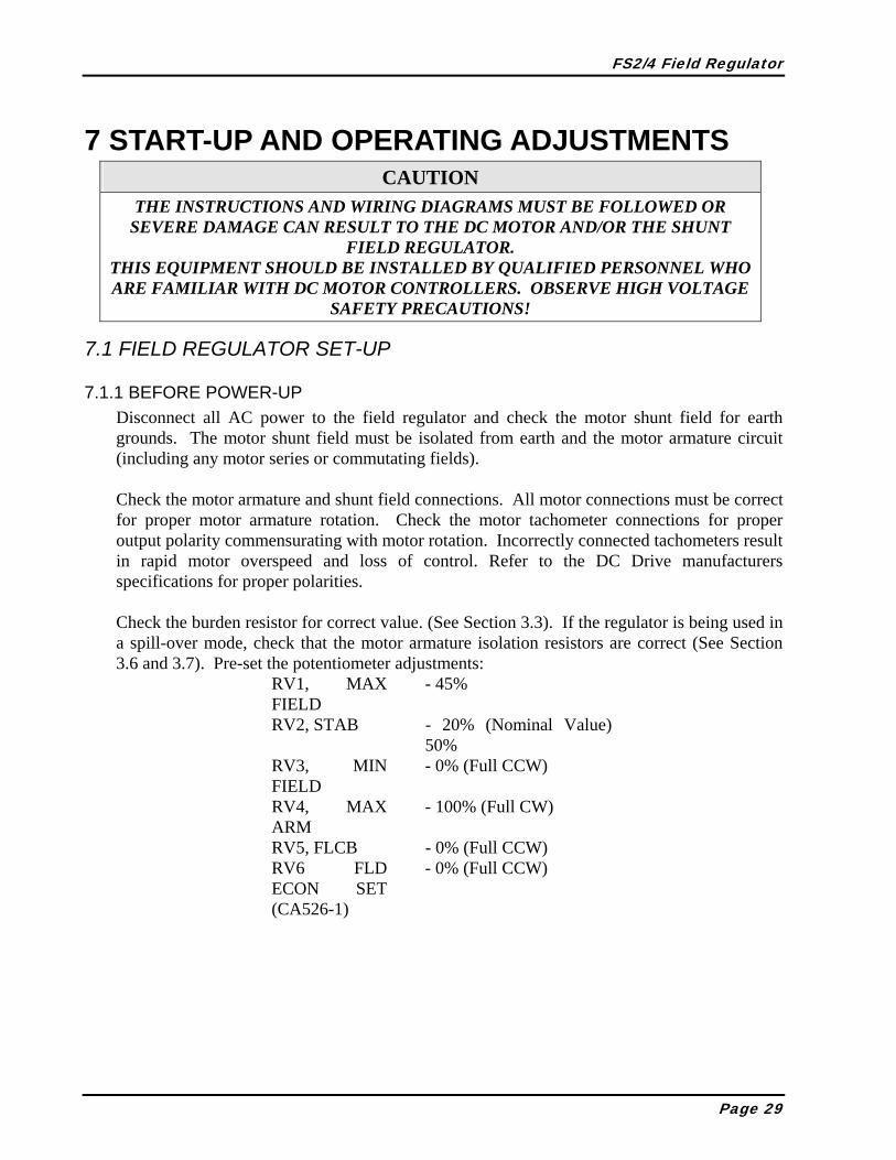
7 START-UP AND OPERATING ADJUSTMENTS CAUTION THE INSTRUCTIONS AND WIRING DIAGRAMS MUST BE FOLLOWED OR
SEVERE DAMAGE CAN RESULT TO THE DC MOTOR AND/OR THE SHUNT FIELD REGULATOR.
THIS EQUIPMENT SHOULD BE INSTALLED BY QUALIFIED PERSONNEL WHO ARE FAMILIAR WITH DC MOTOR CONTROLLERS. OBSERVE HIGH VOLTAGE
SAFETY PRECAUTIONS!
7.1 FIELD REGULATOR SET-UP
7.1.1 BEFORE POWER-UP Disconnect all AC power to the field regulator and check the motor shunt field for earth grounds. The motor shunt field must be isolated from earth and the motor armature circuit (including any motor series or commutating fields). Check the motor armature and shunt field connections. All motor connections must be correct for proper motor armature rotation. Check the motor tachometer connections for proper output polarity commensurating with motor rotation. Incorrectly connected tachometers result in rapid motor overspeed and loss of control. Refer to the DC Drive manufacturers specifications for proper polarities. Check the burden resistor for correct value. (See Section 3.3). If the regulator is being used in a spill-over mode, check that the motor armature isolation resistors are correct (See Section 3.6 and 3.7). Pre-set the potentiometer adjustments:
RV1, MAX FIELD
- 45%
RV2, STAB - 20% (Nominal Value) 50%
RV3, MIN FIELD
- 0% (Full CCW)
RV4, MAX ARM
- 100% (Full CW)
RV5, FLCB - 0% (Full CCW) RV6 FLD ECON SET (CA526-1)
- 0% (Full CCW)
Page 29
FS2/4 Field Regulator
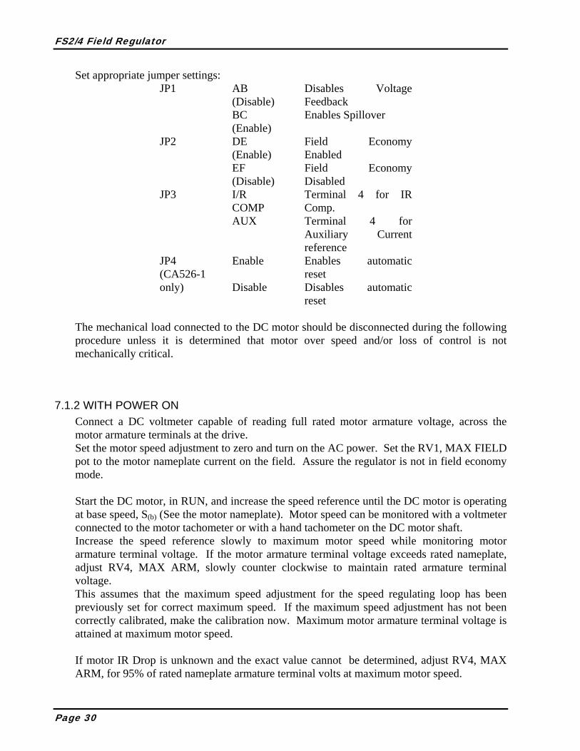
Set appropriate jumper settings: AB (Disable)
Disables Voltage Feedback
JP1
BC (Enable)
Enables Spillover
DE (Enable)
Field Economy Enabled
JP2
EF (Disable)
Field Economy Disabled
I/R COMP
Terminal 4 for IR Comp.
JP3
AUX Terminal 4 for Auxiliary Current reference
Enable Enables automatic reset
JP4 (CA526-1 only) Disable Disables automatic
reset The mechanical load connected to the DC motor should be disconnected during the following procedure unless it is determined that motor over speed and/or loss of control is not mechanically critical.
7.1.2 WITH POWER ON Connect a DC voltmeter capable of reading full rated motor armature voltage, across the motor armature terminals at the drive. Set the motor speed adjustment to zero and turn on the AC power. Set the RV1, MAX FIELD pot to the motor nameplate current on the field. Assure the regulator is not in field economy mode. Start the DC motor, in RUN, and increase the speed reference until the DC motor is operating at base speed, S(b) (See the motor nameplate). Motor speed can be monitored with a voltmeter connected to the motor tachometer or with a hand tachometer on the DC motor shaft. Increase the speed reference slowly to maximum motor speed while monitoring motor armature terminal voltage. If the motor armature terminal voltage exceeds rated nameplate, adjust RV4, MAX ARM, slowly counter clockwise to maintain rated armature terminal voltage. This assumes that the maximum speed adjustment for the speed regulating loop has been previously set for correct maximum speed. If the maximum speed adjustment has not been correctly calibrated, make the calibration now. Maximum motor armature terminal voltage is attained at maximum motor speed. If motor IR Drop is unknown and the exact value cannot be determined, adjust RV4, MAX ARM, for 95% of rated nameplate armature terminal volts at maximum motor speed.
Page 30

FS2/4 Field Regulator
The motor IR Drop can be determined by operating the DC motor in a
mechanical stall. DC motors can be mechanically stalled by removing shunt field excitation and mechanically locking the motor armature. The armature regulator current limits must be set to regulate 100% rated motor armature current. Measure the IR voltage Drop across the motor terminals at the motor armature connections in the controller cabinet.
With the motor operating at maximum speed, adjust RV3, MIN FIELD, slowly clockwise until the motor armature terminal voltage increases slightly. Adjust RV3 slowly counter clockwise until the motor armature terminal voltage is equal to the value in Step 7.1.2.4. Observe that the minimum bar on the LED display, LB1, is ON. Slowly increase RV5, FLCB clockwise until the field loss relay opens and LD2 goes out. Turn this pot 5% Counter Clockwise to set the field loss point slightly less than the minimum field current required for the motor. Press the reset button and observe that LD2 is again illuminated.
*NOTE: The field loss relay will often cause an emergency stop or trip the drive, if it opens. Check the circuitry in which this contact has been installed before performing this step and modify this procedure if necessary.
Decrease the motor speed and observe that motor armature terminal voltage remains relatively constant in the shunt field range and decreases at less than motor base speed. Motor shunt field current must be minimum at maximum motor speed and increase to rated shunt field current at motor base speed. Shunt field current remains at rated maximum current at less than motor base speed. The stability is set by RV2, STAB, and has a nominal set point of 20%. With shunt field range in excess of 2 to 1, it may be necessary to increase STAB clockwise for rapid motor acceleration. Motor armature voltage loop response may be observed on Terminal 3 with respect to common. If Field Economy is to be utilized on the CA526-1, connect a 120VAC signal to terminals 7 and 8 or a dry contact to terminal 13 and 14. After approx. 4.5 minutes the unit should go into field economy mode. Use RV6 to set the field level that you wish during field economy. Keep in mind that if this value is to be lower than the minimum field level that is attained during operation the MIN FLD pot RV3 may have to be adjusted to attain this lower current setting.
Page 31

FS2/4 Field Regulator
8 TYPICAL CONNECTIONS 8.1 FS2-12-2/4 CONNECTED AT 240VAC
AA
VOLT
AG
E FB
(FRO
M D
C M
OTO
R)
ARM
ATUR
E
BB
NO
TES:
RBUR
D =
SEE
SEC
TION
6.4
.1
CO
NN
ECTE
D F
OR
240V
MAX
.IN
PUT
ARM
.
RAA
RBB +
15
FLC
B
STA
B
ARM
.
CA5
26
MAX
.M
IN.
500
IF FIEL
DFI
ELD T1
R
FU2
FU1AC
PO
WER
240
VAC
L1L2
30
(600
V)
FS2-
12-2
/4
ATM
PB1
- RES
ET F
IELD
LO
SS F
AULT
LD2
- ILL
UMIN
ATED
WH
EN F
IELD
IS N
ORM
AL
LD1
- ILL
UMIN
ATED
IN F
LD E
CO
NO
MY
3 4 5 6
CO
NTR
OL
120
VAC
MX
JP1
- BC
VO
LTAG
E F.
B.FP
TB
RESE
T
R BU
RD
FLD
ECO
N
LD1R
-15
-VAB
S
IN IR C
OM
P.
AUX.
/
LOSS
FLD
LD2R
IFB
OUT
CO
M
AMPS
LB1
LIN
K FO
R 24
0VS 1 2
PB1
FPTA
PPW
R
JP2
- DE
FIEL
D E
CO
NO
MY
FLR
8
FIEL
D
7
ECO
NO
MY
910
-
EF
DIS
ABLE
FIE
LD E
CO
NO
MY
JP2
- JUM
PER
DE
TO E
NAB
LE F
IELD
EC
ON
OM
Y
-
JUM
PER
BC F
OR
VOLT
AGE
SPIL
LOVE
R
JP1
- JU
MPE
R A
B FO
R FI
ELD
CUR
REN
T C
ON
TRO
L
FPTB
4
RS
SCR 2
PPW
R
FPTA
SCR
+15
V-1
5V
F+
D1
D2
F+
500:
1
DC
CT
P2
CA3
57
F-F-
F2
DC
MO
TOR
F1
FIEL
D
JP3
- JUM
PER
I/R C
OM
P FO
R US
E O
F TE
RMIN
AL 4
FO
R IR
CO
MP
-
AUX
USE
D F
OR
TERM
INAL
4 A
S C
URRE
NT
REFE
REN
CE
JP3
- AUX
FO
R C
URRE
NT
REF
INPU
T
(500
V)AT
Q
FU3
30
14
TO C
ALC
ULAT
E RA
A, R
BB IN
KILO
HM
S,
RAA
= R
BB =
2x(
VARM
-90V
)
Page 32

FS2/4 Field Regulator
8.2 FS2A-12-2/4 CONNECTED AT 240VAC
AA BB
NO
TES:
RBUR
D =
+15
FLC
B
CA5
26
MA
X.
500
IF FIEL
D
T1R
FU2
FU1AC P
OW
ER
240
VAC
L1L2
30
30
(600
V) FS2A
-12-
2/4
ATM
PB1
- RE
SET
FIEL
D L
OSS
FA
ULT
LD2
- IL
LUM
INAT
ED W
HEN
FIE
LD IS
NO
RMA
L
3 4 5 6
FPTB
RESE
T
R BU
RD
-15
-VA
BS
IN IR C
OM
P.
AUX.
/
LOSS
FLD
LD2R
IFB
OUT
CO
M
AM
PS
LB1
LIN
K FO
R 24
0VS 1 2
PB1
FPTA
PPW
R
FLR
87
910
FPTB
4
RS
SCR 2
PPW
R
FPTA
SCR
+15
V-1
5V
F+
D1
D2
F+
500:
1
DC
CT
P2
CA3
57
F-F-
F2
DC
MO
TOR
F1
FIEL
D
JP3
- JU
MPE
R I/R
CO
MP
FOR
USE
OF
TERM
INAL
4 F
OR
IR C
OM
P
-
AUX
USED
FO
R TE
RMIN
AL 4
AS
CUR
REN
T RE
FERE
NC
E
JP3
- AUX
FO
R C
URRE
NT
REF
INPU
T
(500
V)AT
Q
FU3
0-(-1
0)V
REFE
REN
CE
14
SEE
SEC
TION
6.4
.1
CO
NN
ECTE
D F
OR
240V
Page 33

FS2/4 Field Regulator
8.3 FS4-12-2/4 CONNECTED AT 240VAC
AA
VOLT
AGE
FB
(FRO
M D
C M
OTO
R)
ARM
ATUR
E
BB
NO
TES:
RBUR
D =
RAA
= R
BB =
2x(
VARM
-90V
)
TO C
ALC
ULAT
E RA
A, R
BB IN
KILO
HM
S,
MAX
.IN
PUT
ARM
.
RAA
RBB +
15
FLC
B
STA
B
ARM
.
CA5
26
MAX
.M
IN.
500
IF FIEL
DFI
ELD T1
R
FU2
FU1AC
PO
WER
240
VAC
L1L2
30
(600
V)
FS4-
12-2
/4
ATM
PB1
- RES
ET F
IELD
LO
SS F
AUL
T
LD2
- IL
LUM
INAT
ED W
HEN
FIE
LD IS
NO
RMAL
LD1
- IL
LUM
INAT
ED IN
FLD
EC
ON
OM
Y
3 4 5 6
CO
NTR
OL
120
VAC
MX
JP1
- BC
VO
LTAG
E F.
B.FP
TB
RESE
T
R BU
RD
FLD
ECO
N
LD1R
-15
-VAB
S
IN IR C
OM
P.
AUX
. /
LOSS
FLD
LD2R
IFB
OUT
CO
M
AM
PS
LB1
LIN
K FO
R 24
0VS 1 2
PB1
FPTA
PPW
R
JP2
- D
E FI
ELD
EC
ON
OM
Y
FLR
8
FIEL
D
7
ECO
NO
MY
910
-
EF
DIS
ABLE
FIE
LD E
CO
NO
MY
JP2
- JU
MPE
R D
E TO
EN
ABLE
FIE
LD E
CO
NO
MY
-
JUM
PER
BC F
OR
VOLT
AG
E SP
ILLO
VER
JP1
- JU
MPE
R A
B FO
R FI
ELD
CUR
REN
T C
ON
TRO
L
FPTB
4
RS
SCR 2
PPW
R
FPTA
SCR
+15
V-1
5V
F+F+
500:
1
DC
CT
P2
CA3
57
F-F-
F2
DC
MO
TOR
F1
FIEL
D
JP3
- JU
MPE
R I/R
CO
MP
FOR
USE
OF
TERM
INAL
4 F
OR
IR C
OM
P
-
AUX
USE
D F
OR
TERM
INA
L 4
AS
CUR
REN
T RE
FERE
NC
E
JP3
- A
UX F
OR
CUR
REN
T RE
F
INPU
T
(500
V)AT
Q
FU3
30
14
SCR
1
3
SCR
CO
NN
ECTE
D F
OR
240V
SEE
SEC
TION
6.4
.1
Page 34
FS2/4 Field Regulator
8.4 FS4A-12-2/4 CONNECTED AT 240V
AA BB
NO
TES:
RBUR
D =
+15
FLC
B
CA5
26
MA
X.
500
IF FIEL
D
T1R
FU2
FU1AC P
OW
ER
240
VAC
L1L2
30
30
(600
V) FS4A
-12-
2/4
ATM
PB1
- RE
SET
FIEL
D L
OSS
FA
ULT
LD2
- IL
LUM
INAT
ED W
HEN
FIE
LD IS
NO
RMA
L
3 4 5 6
FPTB
RESE
T
R BU
RD
-15
-VA
BS
IN IR C
OM
P.
AUX.
/
LOSS
FLD
LD2R
IFB
OUT
CO
M
AM
PS
LB1
LIN
K FO
R 24
0VS 1 2
PB1
FPTA
PPW
R
FLR
87
910
FPTB
4
RS
SCR 2
PPW
R
FPTA
SCR
+15
V-1
5V
F+
SCR
SCR
F+
500:
1
DC
CT
P2
CA3
57
F-F-
F2
DC
MO
TOR
F1
FIEL
D
JP3
- JU
MPE
R I/R
CO
MP
FOR
USE
OF
TERM
INAL
4 F
OR
IR C
OM
P
-
AUX
USED
FO
R TE
RMIN
AL 4
AS
CUR
REN
T RE
FERE
NC
E
JP3
- AUX
FO
R C
URRE
NT
REF
INPU
T
(500
V)AT
Q
FU3
0-(-1
0)V
REFE
REN
CE
14
SEE
SEC
TION
6.4
.1
CO
NN
ECTE
D F
OR
240V
1 3
Page 35
FS2/4 Field Regulator
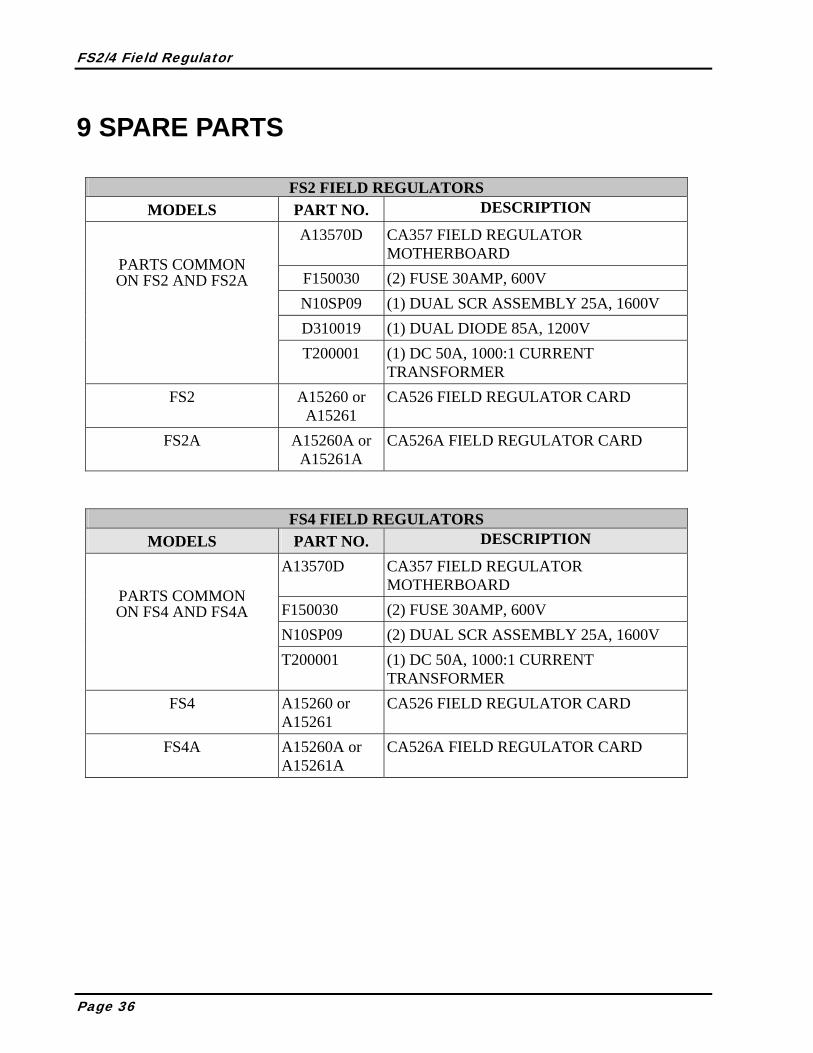
9 SPARE PARTS
FS2 FIELD REGULATORS MODELS PART NO. DESCRIPTION
A13570D CA357 FIELD REGULATOR MOTHERBOARD
F150030 (2) FUSE 30AMP, 600V N10SP09 (1) DUAL SCR ASSEMBLY 25A, 1600V D310019 (1) DUAL DIODE 85A, 1200V
PARTS COMMON ON FS2 AND FS2A
T200001 (1) DC 50A, 1000:1 CURRENT TRANSFORMER
FS2 A15260 or A15261
CA526 FIELD REGULATOR CARD
FS2A A15260A or A15261A
CA526A FIELD REGULATOR CARD
FS4 FIELD REGULATORS MODELS PART NO. DESCRIPTION
A13570D CA357 FIELD REGULATOR MOTHERBOARD
F150030 (2) FUSE 30AMP, 600V N10SP09 (2) DUAL SCR ASSEMBLY 25A, 1600V
PARTS COMMON ON FS4 AND FS4A
T200001 (1) DC 50A, 1000:1 CURRENT TRANSFORMER
FS4 A15260 or A15261
CA526 FIELD REGULATOR CARD
FS4A A15260A or A15261A
CA526A FIELD REGULATOR CARD
Page 36

FS2/4 Field Regulator
SAF Drives Inc. 18 Neville Street, Unit C www.safdrives.com Tel: 519-662-6489 Email: [email protected] Fax: 1-866-280-5247 Toll Free: 1-800-3-ASK-SAF
Page 37

www.safdrives.comemail: [email protected]
(Replies given within 24 hours)
18 Neville Street, Unit CNew Hamburg, ON N3A 4G7
Tel: 519-662-6489Fax: 1-866-280-5247
Installation & Operating Procedures
FS2 and FS4 Field Regulator


![FS SERIES - masterele.netmasterele.net/doc/FS2_datasheet.pdf · FS2 Socket for 2-pole FR relay S 2 2-2 DIMENSIONS mm [inch] FS2-O .53W FS2 MASTERELE www masterele.net SPAIN IOA/300V](https://img.dokumen.tips/doc/110x75/5e53a0c24a01b6350f50d668/fs-series-fs2-socket-for-2-pole-fr-relay-s-2-2-2-dimensions-mm-inch-fs2-o-53w.jpg)


![FS2-2 썎 V [ ݊ [ h])](https://img.dokumen.tips/doc/110x75/61900dd5f1cf294ceb1e809a/fs2-2-v-h.jpg)


