Embed Size (px)
Citation preview

NGC-30
InstallatIon Manual
EN-RaychemNGC30-IM-INSTALL114 R6IndustrIal Heat tracIng solutIons


3
table of contents
section 1 – overview .............................................................................................................................................. 4 1.1 Introduction ......................................................................................................................................................................................... 4
section 2 – Installation and Wiring ........................................................................................................................ 5 2.1 Introduction .......................................................................................................................................................................................... 5 2.2 Initial Inspection ................................................................................................................................................................................... 5 2.3 Operating Environment ........................................................................................................................................................................ 5 2.4 Installation Location............................................................................................................................................................................. 5 2.5 Mounting Procedures ........................................................................................................................................................................... 5 2.6 Wiring Procedures ............................................................................................................................................................................... 6 2.6.1 Incoming Power With Distribution System .............................................................................................................................. 6 2.6.2 Outgoing Power With Distribution System .............................................................................................................................. 6 2.6.3 Incoming RTD Wiring ............................................................................................................................................................... 6 2.6.4 Connecting the RS-485 Device Network ................................................................................................................................. 7 2.7 Connections for Remote Annunciation .............................................................................................................................................. 10 2.8 RS-232, RS-485 or Ethernet Remote Port Connections to a Host Computer ................................................................................... 11 2.9 Testing the NGC-30 System ............................................................................................................................................................... 12
section 3 – raychem ngc-30 components and operation ................................................................................... 13 3.1 User Interface Terminal (NGC-UIT) ................................................................................................................................................... 13 3.1.1 LED Status ............................................................................................................................................................................. 14 3.1.2 Configuration Switches .......................................................................................................................................................... 14 3.1.1 Reset Switch .......................................................................................................................................................................... 14 3.2 Card Rack Module (NGC-30-CRM/-CRMS) and Current Transformer Module (NGC-30-CTM) ......................................................................................................................................................................................... 14 3.3 Card Rack (NGC-30-CR) ..................................................................................................................................................................... 16 3.4 Voltage Monitoring Module (NGC-30-CVM) – Optional ...................................................................................................................... 16 3.5 Remote Monitoring Module (RMM2) – Optional ................................................................................................................................ 17 3.6 Raychem RMC .................................................................................................................................................................................... 17 3.7 Remote User Interface Terminal (NGC-UIT-ORD-12) ....................................................................................................................... 18
section 4 – appendices ........................................................................................................................................ 19 Appendix A – NGC-30 Components ......................................................................................................................................................... 19 Appendix B – NGC-30-CRM/-CRMS Specifications................................................................................................................................. 20 Appendix C – NGC-UIT Specifications ..................................................................................................................................................... 21 Appendix D – Device Address .................................................................................................................................................................. 22

4
sectIon 1 – overvIeW
1.1 IntroductionThe Raychem NGC-30 is a control and monitoring system used with electric heat-tracing. This manual provides information pertaining to the installation, operations, testing, adjustment, and maintenance of all components of the Raychem NGC-30. For information about how to program the NGC-30, see the Raychem NGC-30 Programming Guide (INSTALL-111)A NGC-30 system has by default a User Interface Terminal (NGC-UIT). From there on several components can be used to complete the system. The other individual components are: card rack (NGC-30-CR), card rack modules for electromechanical relays (CRM) and solid-state relais (CRMS), current transformer module (NGC-30-CTM), Remote Module for Control (RMC), Remote Monitoring Module (RMM) and Voltage Monitoring Module (NGC-30-CVM).The information coincides with the specific releases of firmware for the User Interface Terminal (NGC-UIT) and controller components, which are listed in Table 1.1 below. As Pentair releases new firmware to significantly modify or enhance any of these components, new documentation will accompany these releases. To ensure that the correct documentation is being used for your particular version of the Raychem User Interface Terminal (NGC-UIT), compare the firmware version number of each component against the number listed in the table below. As subsequent changes are made, supplements to this document will be included in manuals shipped after the firmware is released. Supplements will make specific reference to the operation or functional change.Copies of this manual and updates may be downloaded from the Literature section of www.pentairthermal.com.
table 1.1 component versions
component version number
NGC-CRM/CRMS V1.0X
NGC-UIT V1.1X
MONI-RMM2
MONI-RMC

5
sectIon 2 – InstallatIon and WIrIng
2.1 Introduction
WarnIng: Electrical Hazard! Ensure all personnel involved in installation, servicing, and programming are qualified and familiar with electrical equipment, their ratings, and proper practices and codes. Multiple voltages and signal levels may be present during the installation, operation, and servicing of this product. Do not power the product until the safety provisions outlined in this section have been observed.This section includes information regarding the initial inspection, preparation for use, and wiring instructions for the components of the Raychem NGC-30.
2.2 Initial InspectionInspect the shipping container for damage. If the shipping container or cushioning material is damaged, it should be kept until the contents of the shipment have been verified for completeness and the equipment has been checked mechanically and electrically. Procedures for installing the Raychem NGC-30 are given in this section. If the shipment is incomplete, mechanically damaged, defective in any way, or does not pass the electrical performance tests, notify the nearest Pentair representative. If the shipping container is damaged, or the cushioning material shows signs of stress, notify the carrier as well as your Pentair representative. Keep the shipping materials for the carrier’s inspection.
2.3 operating environmentThere are two types of User Interface Terminals (UITs) available with the NGC-30 panel, as shown in Table 2.1 below.
For model numbers see appendix A (NGC-30 Components)
WarnIng: Some wiring configurations will use more than one power source. All power sources must be de-energized prior to performing any maintenance on a card rack module or its heating circuit. The operating environment should be within the limitations specified for the Raychem NGC-30 components as outlined in Appendices B, C, and D.
2.4 Installation location The wide ambient operating temperature range of the Raychem NGC-30 permits installation in almost any convenient location. Considerations should include: expected atmospheric conditions (weather), accessibility for maintenance and testing, the location of existing conduits, and hazardous area rating. Ambient temperature conditions may affect load current ratings.
cautIon: Always be sure that the intended location is classified as an area that the product is approved for use in as defined by Article 500 of the National Electrical Code and/or Part I, Section 18 of the Canadian Electrical Code.
2.5 Mounting ProceduresA NGC-30 system can be bought as a complete power distribution panel. Each NGC-30 panel includes a set of “As Built” drawings that have been engineered, designed, and drafted based upon the model number and any special requirements that were requested when ordering. When bought as a complete system, the “As Built” drawings include an elevation/layout (with bill of materials) and schematics. If these drawings are not included, contact your Pentair Representative and request the “As Built” drawings for your panel. Upon request, an electronic copy of these drawings can be provided. For mounting the panel, locate the elevation and layout drawing which includes a bill of materials. The enclosure mounting information will be provided on the “As Built” drawings.
table 2.1 ngc-30 user Interface terminals (uIts)
uIt type output type area classification usage
NGC-UIT-ORD Electrical mechanical contactors or solid-state relays Ordinary IP 54 (NEMA 12)
NGC-UIT-OUT Electrical mechanical contactors or solid-state relays Outdoors IP 54 (NEMA4 or 4X)
NGC-UIT-ORD-12UIT is separated from Power distribution panel (including contactors) but build into a small panel, ready to be mounted on the wall.
NGC-UIT-ORD-12 must be installed in an Ordinary area IP 54 (NEMA 12)

6
2.6 Wiring ProceduresIn case the system is bought as a complete panel, refer to the “As Built” schematics for wiring of incoming / outgoing power and incoming RTD connections. This paragraph describes the system when it is build by TTC as a complete panel / solution.In case the customer buys the NGC-30 as components only, then the following paragraphs don’t apply.
2.6.1 IncoMIng PoWer WItH dIstrIbutIon sYsteMMain Circuit Breaker Locate the main circuit breaker in the panel by using the supplied elevation/layout drawing, and connect per the associated schematic drawings. Depending upon the size and type of main circuit breaker and voltage loss calculations, use the appropriate size and number of wires to connect to the main circuit breaker. Branch Circuit Breakers The branch circuit breakers are pre-wired to the contactors or solidstate relays in the panel, so no further incoming power wiring is required to these circuit breakers.
2.6.2 outgoIng PoWer WItH dIstrIbutIon sYsteMLoad Power Terminal Blocks Locate the outgoing heater terminal blocks using the supplied elevation/layout drawing, and connect per the associated schematic drawings. Depending upon the size of the branch circuit breaker and voltage loss calculations, use the appropriate size and number of wires to connect from the panel’s Load Power Terminal Blocks to the heat-trace power junction box.
Fig. 2.2 Heat trace power wiring diagram for a NGC-30 equipped with CRM modules
2.6.3 IncoMIng rtd WIrIngordinary Installations Wired to terminal block in PanelThe RTD wiring from the NGC-30-CRM/-CRMS pre-wired to RTD terminals. The field RTD wiring (3-wire with shield) will be terminated by the installer at the RTD terminal blocks. Refer to the Installation Drawings for the RTD Termination Schedule. In case the RTD info is collected via RMMs in the field than the RTD wiring need to be brought back to the RMM. The RMM is connected via a RS-485 ModBus connection back to the panel.
See Fig. 2.4 for a typical RTD installation to NGC-30 CRM(S) module. For connection to a RMM see RMM installation manual Install-061.
* Reference panel drawing for terminal block numberFig. 2.4 Typical RTD installation connected up to CRM(S) module
REDRED
(–)(+)
)+( )+(
)–( )–(
44332211
Card Rack Module
WH WH WH
WH
CRM
RED REDRED
SHLD SHLDREDRED
RED
OPEN
TB*
CHASSIS GRD
RTD- RTD-
NGC-30-CRM/-CRMS PanelTerminal Block
Field Wiring
Heat trace cable
TB- (Y)
CRMTB5
EMR orSSR
contactsRCD
Load PowerTerminal
Block
Heat tracejunction
box
17
16
15
14
13Cable-CT*
* Represents HTC circuit number 1-40
** Reference panel drawing for terminal block number
LCGF
CTMconnector
X
x
x

7
2.6.4 connectIng tHe rs-485 devIce netWorKThe NGC-UIT display is typically linked to a network of Raychem NGC-30-CRM/-CRMS, RMC and optional RMM2. These are connected to the Raychem NGC-UIT using an RS-485 communication cable (shielded, two conductor, twisted pair). The following illustration shows how the RS-485 network for the NGC-UIT system may be configured.
Fig. 2.5 RS-485 network configuration for the NGC-UIT system
In order for the RS-485 network to work properly, you must enable the termination resistor for the first and last device. The devices shown in gray in Fig. 2.5 represent the devices for which you must enable the termination resistors. The devices that are not grayed out represent the devices for which you should not enable the termination resistors.
TB 12
MSB LSB
TB 7 TB 6TB 13 TB 14 TB 15 TB 16 TB 17
TB 1 TB 2 TB 3 TB 4 TB 5
TB 191 2 3
0
Jumper
NGC-CRM/-CRMS
RMM2
TB 12
MSB LSB
TB 7 TB 6TB 13 TB 14 TB 15 TB 16 TB 17
TB 1 TB 2 TB 3 TB 4 TB 5
TB 191 2 3
0
Jumper
0
NGC-CRM/-CRMS
TB 12
MSB LSB
TB 7 TB 6TB 13 TB 14 TB 15 TB 16 TB 17
TB 1 TB 2 TB 3 TB 4 TB 5
TB 191 2 3
NGC-CRM/-CRMS
TB 12
MSB LSB
TB 7 TB 6TB 13 TB 14 TB 15 TB 16 TB 17
TB 1 TB 2 TB 3 TB 4 TB 5
TB 191 2 3
NGC-CRM/-CRMS
TB 12
MSB LSB
TB 7 TB 6TB 13 TB 14 TB 15 TB 16 TB 17
TB 1 TB 2 TB 3 TB 4 TB 5
TB 191 2 3
NGC-CRM/-CRMSRMM2
NGC-UIT
RMM2
0
RMM2
NGC-UITNGC-UITNGC-U
Device must be mounted in series.
(Terminated devices are shown in gray)
Branching of the network is not allowed.
Connect no more than two RS-485 cables to any device.
ON
TxD
IO/RN
IO/ER
RxD
CRC
750-
312
D1 D2
D1 D2
24V 0V
24V
0V
L L
N N
L
N
V IN
750-400 750-612 750-512
RMC
ON
TxD
IO/RN
IO/ER
RxD
CRC
750-
312
D1 D2
D1 D2
24V 0V
24V
0V
L L
N N
L
N
V IN
750-400 750-612 750-512
RMC

8
optional rMM2 installed in the fieldRefer to the RMM2 Installation Instructions (Install-061) for field installation instructions. You must connect a RS-485 connection from the RMM2 to an open RS-485 connector in the NGC-30 panel. To make this connection, a pre-wired terminal block will be provided in the NGC-30 panel. Connect the RS-485 wire from the RMM2 to terminal block (see panel drawings for more details) while maintaining the correct polarity. If the RMM2 is the first or last device in the RS-485 network, connect the J17 termination jumper to pins 1 and 2. If the RMM2 is not the first or last device in the RS-485 network, connect the J17 termination jumper to pins 2 and 3.
Fig. 2.6 RMM2 RS-485 field wiring and termination jumper setting
remote ngc-uIt-ord-PnlRefer to the NGC-UIT-ORD-PNL Installation Instructions (Install-118) for field installation instructions. You must make an RS-485 connection from the NGC-UIT-ORD-PNL to the NGC-30 panel where the components like CRM / CRMS and/or RMC are installed. To make this connection, a pre-wired terminal block has been provided in the NGC-UIT-ORD-PNL and in the NGC-30 panel. If the NGC-UIT-ORD-PNL and/or the NGC-30-CRM/-CRMS is the first or last device in the RS-485 network, see Fig. 2.8 and Table 3.2 for details on how to terminate the RS-485 network.
0
Jumper
RMM2
NGC-UIT-ORD NGC-30-CRM/-CRMS
NGC-30 Panel
RS-485 RS-485
RS-485
BK
WH(–)
S
(+)
S
BK
TB6WH
BK
TB6
3WH
+
–
1
2
3
1
2
S
+
–
S
BK
WH
S
+
–
BK
WH
S
6
4
5
TB4
1
3
2
4
6
5
J171 2 3
Default position (for all RMM2units in network except first or last one)
J171 2 3
Termination mode (first or last RMM2 in network)
Last RMM2 in network
J171 2 3
RS-485 RMC module
BK
TB6WH
S
BK
TB6
6WH
+
–
9
5
6
9
5
S
* Reference panel drawing for terminal block number

9
Fig. 2.7 NGC-UIT-ORD-12 RS-485 field wiring
The following figure shows the RS-485 termination options for the NGC-30-CRM/-CRMS.
Fig. 2.8 Termination of RS-485 network for NGC-30-CRM/-CRMS
ngc-30 panel with ngc-uIt connected to an ngc-30 panel without ngc-uItThis wiring is used when a single UIT in one panel is the central point for multiple Raychem NGC-30 panels. Because the Raychem NGC-UIT can handle up to 260 heat-tracing circuits, it can be cost effective to use one Raychem NGC-UIT for multiple panels. An RS-485 connection must be made from the panel that has the NGC-UIT (panel #1) installed to the NGC-30 panel (panel #2) that does not have the NGCUIT installed (see Fig. 2.9 ). To make this connection, a pre-wired terminal block has been provided in panel #1 and #2. Connect the RS-485 wire from TB* in panel #1 and the other end to TB* in panel #2 maintaining
NGC-30-CRM/-CRMS
TB 12
MSB LSB
TB 7 TB 6TB 13 TB 14 TB 15 TB 16 TB 17
TB 1 TB 2 TB 3 TB 4 TB 5
TB 191 2 3
Normalposition
End of Lineposition
321 321
End of Line (EOL) JumperIf this device (NGC-30-CRM/-CRMS) is the first or last device in the RS-485 network, move the J1 jumper from terminals 2 & 3 to terminals 1 & 2.
+–
NGC-30 Panel #1
NGC-UIT-ORD-12
TB1Line voltage Alarm relay RS-485
1 2 3
TB2 TB3AR
RS-485
NGC-30-CRM/-CRMS #8RS-485 RS-485
BK
TB6WH
BK
TB6
3WH
+
–
1
2
3
1
2
S
+
–
S
BK
WH
S
+
–
BK
WH
S
6
4
5
TB4
RMC module
BK
TB6WH
S
BK
TB6
6WH
+
–
9
5
6
9
5
S

10
the correct polarity. If the NGC-30-CRM/-CRMS is the first or last device in the RS-485 network, see Fig. 2.8 and Table 3.2 for details on how to terminate the RS-485 network.
Fig. 2.9 RS-485 field wiring between two Raychem NGC-30 panels
2.7 connections for remote annunciationRelay 1 on the NGC-UIT has been factory-configured and wired for “Any Alarms”. It will energize a light on the front of the panel if any alarm occurs. Relay 1 was also wired to a common alarm relay/terminal block for remote annunciation of any alarms.
Fig. 2.10 Relay 1 wiring * Reference panel drawings for terminal block numbers
The NGC-UIT has two other Form C alarm relays (configurable through the NGC-30 program) for external alarms. Each relay can be connected to an annunciator light or distributed control system. Each relay’s contacts have been wired from the NGC-UIT to a terminal block in the panel.
Fig. 2.11 Relays 2 and 3 wiring * Reference panel drawings for terminal block numbers
note: The above relays are shown in the energized position without an alarm condition. The relay will change state with an arm condition or loss of power.
NGC-UIT Relay 1
TB*AR–NC
AR–COM Commonalarm output
AR–NO
1
6
8
5
AR
AR
2
3
5
6
7
9
10
11
NGC-UIT Relay 2
UIT-R2-COM
UIT-R2-NC
UIT-R2-NO
4
5
6
NGC-UIT Relay 3
UIT-R3-COM
UIT-R3-NC
UIT-R3-NO
8
7
9
TB* TB*
NGC-UIT-ORD
NGC-30 Panel
RS-485 RS-485
BK
WH(–)
S
(+)
S
BK
TB6WH
BK
TB6
3WH
+
–
1
2
3
1
2
S
+
–
S
BK
WH
S
+
–
BK
WH
S
6
4
5
TB4
1
3
2
4
6
5
RS-485
BK
TB6WH
S
BK
TB6
6WH
+
–
9
5
6
9
5
S
RMC Module(s) NGC-30-CRM/-CRMSModule(s)
RS-485
NGC-30 Panel #2without UIT installed
RS-485 NGC-30-CRM/-CRMSRS-485TB6
BK
TB6
3WH
+
–
1
2
3
1
2
S
+
–
BK
WH
S
+
–
BK
WH
S
3
1
2
TB4
RS-485
BK
TB6WH
BK
TB6
3WH
+
–
1
2
3
1
2
S S
BK
TB6WH
S
BK
TB6
6WH
+
–
9
5
6
9
5
S
RMC Module(s) NGC-30-CRM/-CRMSModule(s)
* Reference panel drawings for terminal block numbers
11
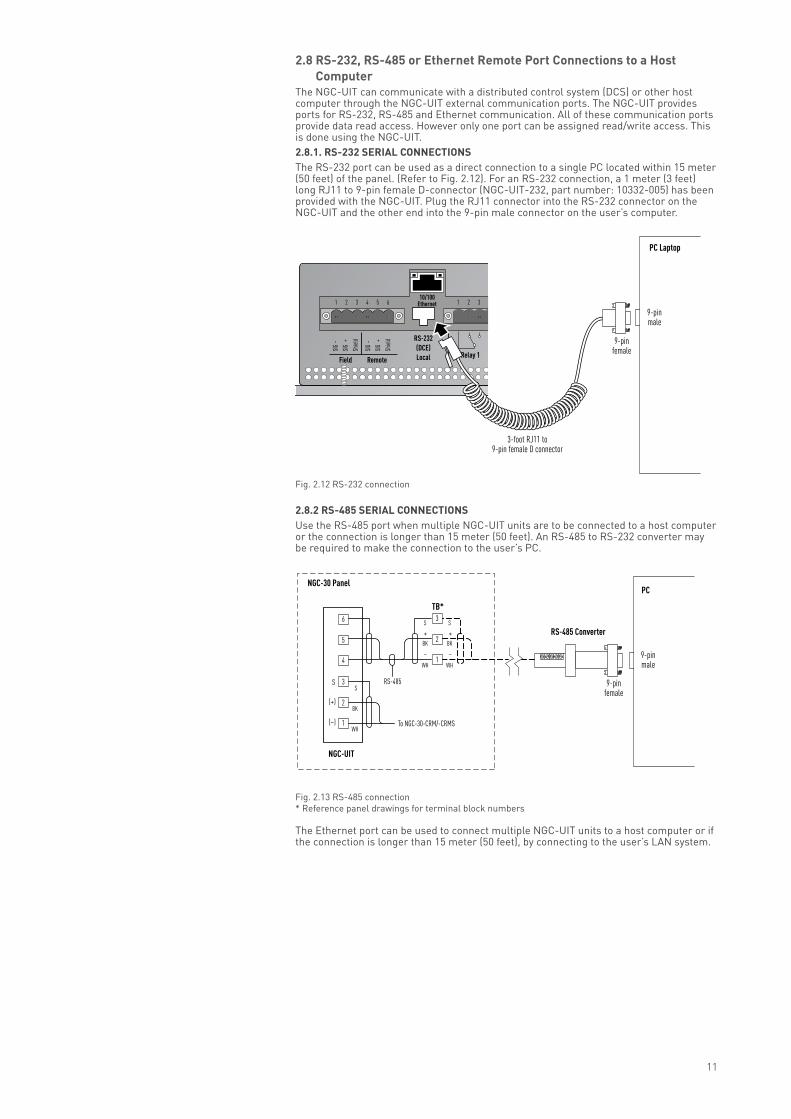
2.8 rs-232, rs-485 or ethernet remote Port connections to a Host computer
The NGC-UIT can communicate with a distributed control system (DCS) or other host computer through the NGC-UIT external communication ports. The NGC-UIT provides ports for RS-232, RS-485 and Ethernet communication. All of these communication ports provide data read access. However only one port can be assigned read/write access. This is done using the NGC-UIT.2.8.1. rs-232 serIal connectIons The RS-232 port can be used as a direct connection to a single PC located within 15 meter (50 feet) of the panel. (Refer to Fig. 2.12). For an RS-232 connection, a 1 meter (3 feet) long RJ11 to 9-pin female D-connector (NGC-UIT-232, part number: 10332-005) has been provided with the NGC-UIT. Plug the RJ11 connector into the RS-232 connector on the NGC-UIT and the other end into the 9-pin male connector on the user’s computer.
Fig. 2.12 RS-232 connection
2.8.2 rs-485 serIal connectIons Use the RS-485 port when multiple NGC-UIT units are to be connected to a host computer or the connection is longer than 15 meter (50 feet). An RS-485 to RS-232 converter may be required to make the connection to the user’s PC.
Fig. 2.13 RS-485 connection * Reference panel drawings for terminal block numbers
The Ethernet port can be used to connect multiple NGC-UIT units to a host computer or if the connection is longer than 15 meter (50 feet), by connecting to the user’s LAN system.
10/100Ethernet
RS-232(DCE)Local
N/L2
Line/
L1
SIG
–
SIG
+
Shiel
d
SIG
–
SIG
+
Shiel
d
11109 321876543
Relay 3Relay 2Relay 1RemoteField
21654321
9-pinmale
PC Laptop
9-pinfemale
3-foot RJ11 to9-pin female D connector
9-pinfemale
9-pinmale
To NGC-30-CRM/-CRMS
NGC-UIT
BK
WH(–)
– –
S
(+)
SRS-485
BK
WH
S
BK
WH
S
1
3
2
1
3
2
4
6
5
TB*
PC
RS-485 Converter
NGC-30 Panel
+ +

12
Fig. 2.14 Ethernet connection
2.9 testing the ngc-30 systemOnce the wiring to the panel has been finished, confirm that it was done properly by completing the following steps:1. Turn the power on to all network devices (NGC-30-CRM/-CRMSs, RMC and optional
RMM2s) and the NGC-UIT.2. Once the NGC-UIT has booted up to the Main screen, Go to the Network |Device Screen
and press “Update Network.”
Fig. 2.15 Network|Devices screen
3. Confirm all devices have been scanned into the Network database.4. If a device or an RTD is installed but does not show up in the Network|Devices Screen,
turn the power off to the system and: For Devices: a. Confirm the device has a unique address (refer to section 3.2 on page 15) b. Confirm the device is being powered c. Confirm the RS-485 connection is in place with the correct polarity (refer to
section 2.6.5 )
For RTDs: a. Confirm the RTD connection is in place with the correct polarity b. Perform a resistance check of the RTD. The resistance should be in a range of
70–250 ohms
Turn the power on to all devices (NGC-30-CRM/-CRMSs, RMC and optional RMM2s) and the NGC-UIT. Once the NGC-UIT has booted up to the Main screen, Go to the Network|Device Screen and press “Update Network.” Confirm all NGC-30-CRM/-CRMS (RMC), RTDs and/or RMM2s have been scanned into the Network database.
10/100Ethernet
RS-232(DCE)Local
SIG
–
SIG
+
Shiel
d
SIG
–
SIG
+
Shiel
d
3
Relay 1RemoteField
21654321
Network node
Ethernet cable
13
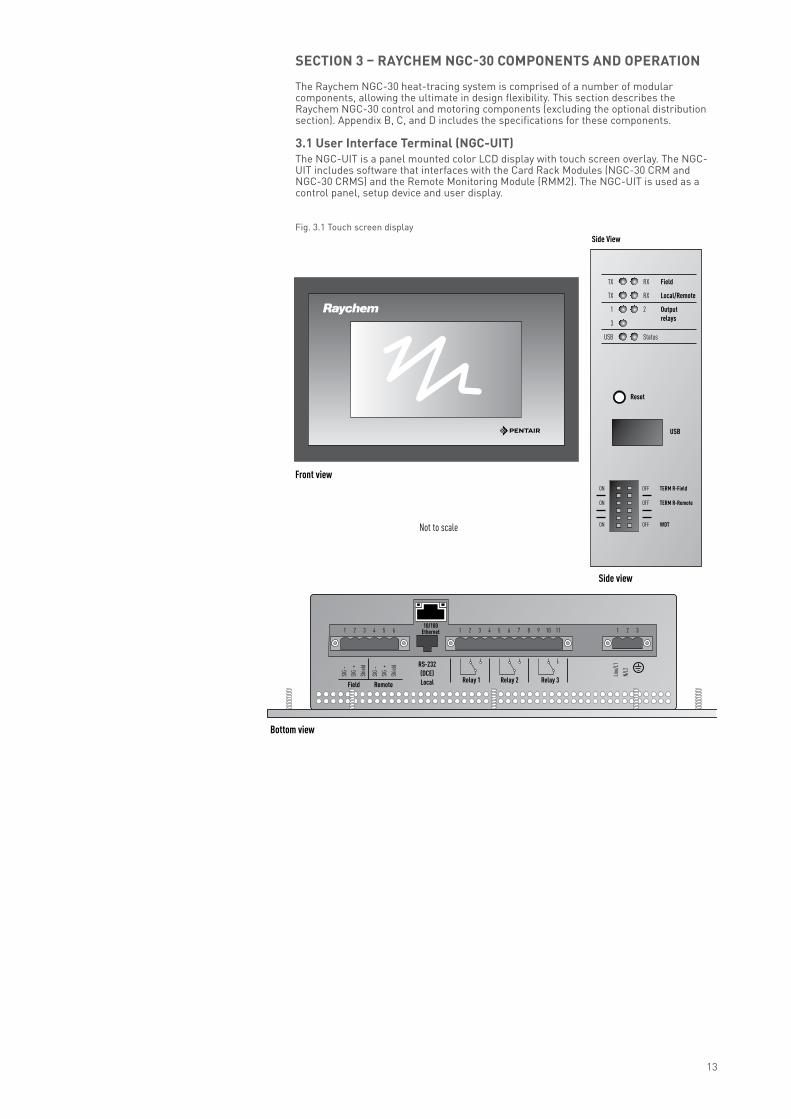
sectIon 3 – raYcHeM ngc-30 coMPonents and oPeratIon
The Raychem NGC-30 heat-tracing system is comprised of a number of modular components, allowing the ultimate in design flexibility. This section describes the Raychem NGC-30 control and motoring components (excluding the optional distribution section). Appendix B, C, and D includes the specifications for these components.
3.1 user Interface terminal (ngc-uIt)The NGC-UIT is a panel mounted color LCD display with touch screen overlay. The NGC-UIT includes software that interfaces with the Card Rack Modules (NGC-30 CRM and NGC-30 CRMS) and the Remote Monitoring Module (RMM2). The NGC-UIT is used as a control panel, setup device and user display.
Fig. 3.1 Touch screen display
Front view
Bottom view
Side view
Not to scale
TX
TX
1
3
USB
RX Field
RX Local/Remote
2 Output relays
Status
Reset
Side View
USB
OFF TERM R-Field
OFF TERM R-Remote
OFF WDT
ON
ON
ON
10/100Ethernet
RS-232(DCE)Local
N/L2
Line/
L1
SIG
–
SIG
+
Shiel
d
SIG
–
SIG
+
Shiel
d
11109 321876543
Relay 3Relay 2Relay 1RemoteField
21654321

14
3.1.1 led statusThe LED Status lights are found on the side of the NGC-UIT-ORD. Refer to Table 3.1 for LED fuctions.
table 3.1 led status light fuctions
3.1.2 confIguratIon sWItcHesThe configuration switches are found on the side of the NGC-UIT-ORD. Refer to Table 3.2 for LED functions.
table 3.2 configuration switch functions
3.1.3 reset sWItcHThe reset switch can also be found on the side of the NGC-UIT-ORD panel. A pointed object is required to press the restart switch and restart the UIT software.
Fig. 3.2 Reset switch
3.2 card rack Module (ngc-30-crM/-crMs) and current transformer Module (ngc-30-ctM)
Each Card Rack Module (NGC-30-CRM, NGC-30-CRMS) and Current Transformer Module (NGC-30-CTM) provide ground-fault and line current sensing, alarming, switching, and RTD input for five Loops. The NGC-30-CRM is used with electromechanical relays. The NGC-30-CRMS is used with solid-state relays. The NGC-30-CRM/-CRMS may be connected to one User Interface Terminal (NGC-UIT).
TX
TX
1
3
USB Status
Reset
USB
ON
ON
ON
USB Status
Reset
USB
USB Status
USB
OFF No power No activity No activity No activity No activityNo USB keydetected
Relay in NO position
Green Normaloperation*
Flicker on receipt ofdata packet
Flicker on transmissionof data packet
Flicker on receipt ofdata packet
Flicker on transmissionof data packet
USB keyinserted*
Relay energizedcontacts in NC position
Yellow
* State controlled by software, all other states controlled by hardware.
UIT loading USB in use*LED functions
TX
TX
1
3
USB
RX Field
RX Local/Remote
2 Output relays
Status
State Status USB RX TX RX TX
Field Local/Remote
Relays
120 Ohm Termination Enabled (Factory Default)
Termination Disabled
TERM R-REMOTE(Remote Port Termination Select)
TERM R-FIELD(Field Port Termination Select)
120 Ohm Termination Enabled
Termination Disabled(Factory Default)
Enable only if this NGC-UIT-ORD is the last in a series of devices connected via RS-485
WDT(Watch Dog Timer)
WDT Enabled(Factory Default)
WDT Disabled WDT should normally be enabled
Configuration Switches
OFF TERM R-Field
OFF TERM R-Remote
OFF WDT
ON
ON
ON
This switch should be enabled if this NGC-UIT-ORD is the first or last in a series of devices connected via RS-485

15
Each NGC-30-CRM/-CRMS must have a unique communication address. The valid address switch range for the NGC-UIT is 1–99. SW1 is the ones digit (0–9) and SW2 is the tens digit (0–9). See Fig. 3.3
Fig. 3.3 Communication address switch
note: When adding an NGC-30-CRM/-CRMS to the system, a network update on the NGC-UIT must be performed.
Fig. 3.4 NGC-30-CRM/-CRMS BoardlLayout
Each NGC-30-CRM/-CRMS has a cluster of nine LED lights to advise the status of the board.Number 3 in Fig. 3.4 shows the location of the LED lights.
LSBMSB
SW1SW2
38
874 5 61
1 Alarm output2 Relay outputs (5x)3 LEDs (9x)4 Fuse5 12 Vdc Inputs (2x)
2 3
bk
9
6 End of Line (EOL) jumper7 RS-485 Communications8 Line & ground-fault sensor inputs (5x)9 R TD Inputsbk Address Switches
NGC-30-CRM/-CRMS
TB 12
MSB LSB
TB 7 TB 6TB 13 TB 14 TB 15 TB 16 TB 17
TB 1 TB 2 TB 3 TB 4 TB 5
TB 191 2 3

16
table 3.3 led display
3.3 card rack (ngc-30-cr)The card rack (NGC-30-CR) has the capability to house one to four card rack modules (CRMs).
Fig. 3.5 NGC-30 card rack
3.4 voltage Monitoring Module (ngc-30-cvM) – optional
The optional voltage sensor can monitor 80–290 Vac. This voltage sensor connects to one of the five line current/ground-fault inputs of the NGC-30-CRM/-CRMS (Note: By using the optional voltage sensors, the NGC-30-CRM/-CRMS board looses one circuit).
Fig. 3.6 NGC-30 voltage monitoring module
Alarm Energized upon Alarm Red
Power Energizes upon power to unit Green
Relays 1, 2, 3, 4, 5 Energizes upon relay closed Red
RX & TX Energizes upon received and transmit of RS-485 data
Amber
Pow
er
Rela
y 1
Rela
y 3
Tx
Alar
m
Rela
y 2
Rela
y 4 Rx
Rela
y 5
LED functions

17
3.5 remote Monitoring Module (rMM2) – optionalThe Raychem remote monitoring module (RMM2) provides additional temperature monitoring capabilities. Each RMM2 accepts up to eight RTDs that measure pipe, vessel, or ambient temperatures. The RMM2 can be installed in the NGC-30 enclosure or can be located in the field to reduce RTD field wiring. A single, twisted pair RS-485 cable connects up to 16 RMM2 for a total monitoring capacity of 128 temperatures.
Fig. 3.7 RMM2 module
Set the RS-485 address for the RMM2 using the rotary switch provided. Note the orientation of the clear plastic cover, then remove the cover. Use a slotted screwdriver to rotate the selector switches to the appropriate positions to select the RS-485 address. The single character visible on the switch indicates the RS-485 address assigned.
Fig. 3.8 RMM2 rotary switch
More details regarding the installation of the MONI-RMM2 can be found in the MONI-RMM2 Installation Instruction (Install-061).
DigiTrace
0
6
0
table 3.4 rMM2 switch settingsswitch settings 0 1 2 3 4 5 6 7 8 9 A B C D E F device address 32 33 34 35 36 37 38 39 40 41 42 43 44 45 46 47

18
3.6 raychem rMcThe remote modules for control (RMC) provide multiple relay outputs for switching heating cable circuits controlled by the Raychem NGC-30 User Interface Terminal. RMC units are modular and may be configured with 2 to 40 relay outputs. Secondly each RMC unit includes two inputs to monitor the status of circuit breakers or power contactors. A single UIT control unit can communicate with up to 10 RMCs via a single, twisted pair RS-485 cable to provide distributed control of up to 250 heating cable circuits.
select the rs-485 address for the rMc unit. Each RMC connected to a NGC-30 Control and monitoring unit must have a unique address; if two RMC units are assigned the same address, communications faults will result. To ensure you assign an unique address to each RMC unit, review the system layout. If a layout document does not exist, create one. Assign an unique address (01–99) to each RMC unit.
set the rs-485 address for the rMc unit. Use a small flat-blade screwdriver to rotate the address switch marked “x1” to the desired address. For an address of 50, set the “x1” to 0 and the x10 to 5. For an address of 59, set x1 to 9 and x10 to 5. Mark the address setting on the RMC label.
For more information see the MONI-RMC installation instructions (Install-079).
3.7 remote user Interface terminal (ngc-uIt-ord-Pnl) The Remote User Interface Terminal (NGC-UIT-ORD-PNL) is a panel mounted display for use with the NGC-30 panel that allows for the user interface to be mounted remotely. Like the NGC-UIT-ORD, it has a 14.61 cm X 8.26 cm (5 ¾ inch x 3 ¼ inch) LCD color display with touch screen technology, and provides an easy user interface for programming with no keyboards or cryptic labels. It is rated IP 54 (NEMA 12), and must be mounted in a nonhazardous indoor area.The User Interface Terminal (NGC-UIT-ORD-PNL) can be mounted remotely (in a nonhazardous location). It communicates via RS-485/RS-232 or 10Base-T Ethernet, selectable; and the port can be used to communicate with the Raychem Supervisor software. For more information, refer to the NGC-UIT-ORD-PNL Installation Instructions (install-118)
Fig. 3.9 Remote user interface terminal
ON
TxD
I/O RUN
I/O ERR
RxD
CRC
750-312
Address x 1
x 10 +
–2
ON
TxD
I/O RUN
I/O ERR
RxD
CRC
750-312RMC label
Set address 0-9
Set address 0x to 9x (x is between 0 and 9)

19
sectIon 4 – aPPendIces
appendix a - ngc-30 componentsThe following table shows all NGC-30 components and its European Part Number
Product name Product description Part number (asW)
NGC-UIT-ORD-E User Interface Terminal 10332-004
NGC-UIT-OUT-E User Interface Terminal for outdoor applications 10332-007
NGC-UIT-ORD-PNL User Interface Terminal with enclosure 10332-006
NGC-30-CRM-E Card Rack Module (EMR) 10720-008
NGC-30-CRMS-E Card Rack Module (SSR) 10720-009
NGC-30-CTM-E Current Transformer Module 10720-010
NGC-30-CVM-E Voltage Monitoring Module (CVM) 10720-011
NGC-30-CR-E Card Rack 10720-012
MONI-RMM2-E Remote Monitoring Module for MoniTrace 200N 307988-000
MONI-RMM2-EX-E Remote Monitoring Module for MoniTrace 200N, ATEX Zone 2 676040-000
MONI-RMC-BASE External Control Module for MoniTrace 200N 309735-000
MONI-RMC-2RO Two Channel Output Module for MoniTrace 200N 920455-000
MONI-RMC-2DI Digital Input Module for MoniTrace 200N 062367-000
MONI-RMC-PS24 Transformer 24V DC, Stabilised 972049-000
MONI-PS12 Transformer 12V DC 1244-001505

20
appendix b - ngc-30-crM/-crMs specifications
table b.1 ngc-30-crM/-crMs specificationsgeneralApprovals/certifications Class I, Div. 2, Groups A,B,C,D
Ex nC IIC T5Class I, Zone 2, AEx nC IIC T5
Class I, Div. 2, Groups A,B,C,DEx nC IIC T5Class I, Zone 2, AEx nC IIC T5
Our products satisfy the requirements of the relevant European Directories
Supply voltage 12 Vdc ± 10%Internal power consumption < 5 W per NGC-30-CRM/-CRMSAmbient operating temperature –40°C to 60° (–40°F to 140°F)Ambient storage temperature –40°C to 75°C (–40°F to 167°F)Environment PD2, CAT IIIMax. altitude 2000 mHumidity 0–90% noncondensingelectromagnetic compatibilityImmunity Heavy industrialEmission Residential, commercial, light industrialtemperature sensors
Type 100 Ω platinum RTD, 3 wire, α = 0.00385 ohms/ohm/°C Can be extended with a 3-conductor shielded cable of 20 ohm maximum per conductor
Quantity Up to five wired directly to each NGC-30-CRM/-CRMS
current sensorsMounting Din Rail – 35 mmQuantity per NGC-30-CTM Five for ground-current measurement Five for line-current measurementline current sensorsMax. current 60 AAccuracy ± 2% of readingground-fault sensorRange 10–200 mAAccuracy ± 2% of rangevoltage sensorRange 80–290 Vac 50/60 HzAccuracy ± 1% of spanoutputsCRM output relays Form A 3-Amp @ 277 Vac max 50/60 HzCRMS SSR outputs 12 Vdc @ 30 mA max per outputAlarm relay SPST 3-Amp @ 277 Vac max 50/60 Hzcommunication to ngc-uItType 2-wire RS-485Cable One shielded twisted pairLength 1200 M (4000 ft.) maximumQuantity Up to 52* NGC-30-CRM/-CRMS may be connected to one NGC-UIT connection terminalsPower supply/pilot relay/RTD/comm port (RS485) 18–12 AWG (0.8 - 3.3mm2)
* May require repeaters
(Russia, Kazakhstan, Belarus) For other countries contact your local Pentair representative.

21
appendix c - ngc-uIt specifications
general
Class I, Div. 2, Groups A,B,C,DEx nC IIC T5Class I, Zone 2, AEx nC IIC T5
Class I, Div. 2, Groups A,B,C,DEx nC IIC T5Class I, Zone 2, AEx nC IIC T5
Our products satisfy the requirements of the relevant European Directories
Supply Voltage 100 – 240 Vac ±10%, .25 A max/25 VA, 50/60 HzOperating temperature –40°C to 65°C (–40°F to 149°F)
EMC Immunity – industrial Emission – commercial/light industrial
Vibration Unit tested to IEC-60068-2-6Shock Unit tested to IEC-60068-2-27Dimensions 260 mm wide X 168 mm high X 76 mm deep (10-1/4” wide X 6-5/8” high X 3” deep)control outputsRelay outputs Three relay outputs, Form C contacts, switching loads up to 277 Vac/3 Amps
Relays may be assigned for alarm outputs11 position Phoenix-style pluggable screw terminal connector with retaining screws
network connectionLocal port/remote RS-485/RS-232, selectable. Port may be used to communicate with Supervisor Software
RS-232 is non-isolated, RJ-11 connectionRS-485, 2-wire isolated. Phoenix-style pluggable screw terminal connector with retaining screws.Maximum number of devices 256. Fail safe design with optional termination resistors.Data rate to 9600 to 57600 baudMaximum cable length for RS-485 not to exceed 1200 m (4000 feet). Cable to be shielded twisted pair
Field port RS-485, 2-wire isolated. Used to communicate with external devices, such as NGC-30-CRM/-CRMS, 5GF-C and RMM2. Maximum cable length not to exceed 1200 m (4000 ft). Cable to be shielded twisted pairPhoenix-style pluggable screw terminal connector with retaining screws. Maximum number of devices 256. Fail safe design with optional termination resistorsData rate to 9600 baud
LAN 10/100 Base-T Ethernet port with Link and Activity Status LEDsUSB port USB 2.0 Host port Type A receptaclestatus ledsRelay Three LEDs showing the ON/OFF Status for each relay, LED ON indicates relay is energizedField Transmit and Receive activityLocal/remote Transmit and Receive activity
USB host Three colors showing status: Green = USB key inserted Red = USB key fault Yellow = USB in use
UIT status Three colors showing system status: Green = Normal condition Red = Fault condition Yellow = Loading software/configuration
lcd display
Display LCD is a 6.5 inch QVGA, color TFT transflective device with integral CCFL backlight. (For use indoors or when protected from direct sunlight)
Touch screen 4-wire resistive touch screen interface for user entry. Usable with gloved fingers
(Russia, Kazakhstan, Belarus) For other countries contact your local Pentair representative.
22
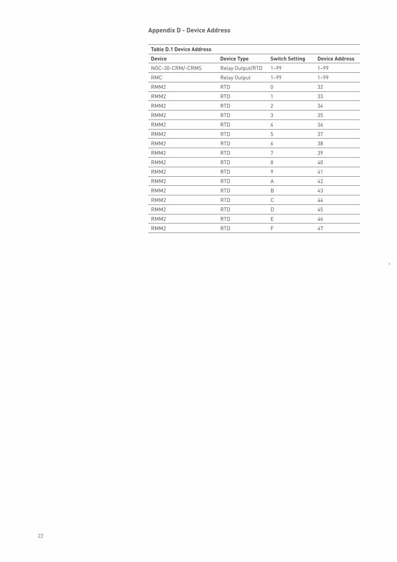
appendix d - device address
table d.1 device address
device device type switch setting device address
NGC-30-CRM/-CRMS Relay Output/RTD 1–99 1–99
RMC Relay Output 1–99 1–99
RMM2 RTD 0 32
RMM2 RTD 1 33
RMM2 RTD 2 34
RMM2 RTD 3 35
RMM2 RTD 4 36
RMM2 RTD 5 37
RMM2 RTD 6 38
RMM2 RTD 7 39
RMM2 RTD 8 40
RMM2 RTD 9 41
RMM2 RTD A 42
RMM2 RTD B 43
RMM2 RTD C 44
RMM2 RTD D 45
RMM2 RTD E 46
RMM2 RTD F 47

www.pentairthermal.com
All Pentair trademarks and logos are owned by Pentair or its global affiliates. Pentair reserves the right to change specifications without prior notice.
© 2009-2014 Pentair.
europe, middle east, africa (emea)Tel: +32 16 213 511Fax: +32 16 213 [email protected]
België / BelgiqueTel. +32 16 21 35 02Fax +32 16 21 36 [email protected]
BulgariaTel./fax +359 56 86 68 86fax +359 56 86 68 [email protected]
ČesKá rePublIKaTel. +420 241 009 215Fax +420 241 009 [email protected]
danmarkTel. +45 70 11 04 00Fax +45 70 11 04 [email protected]
deutschlandTel. 0800 1818205Fax 0800 [email protected]
españaTel. +34 902 125 307Fax +34 91 640 29 [email protected]
franceTél. 0800 906045Fax 0800 [email protected]
hrvatskaTel. +385 1 605 01 88Fax +385 1 605 01 88 [email protected]
italiaTel. +39 02 577 61 51Fax +39 02 577 61 55 [email protected]
lietuva/latvija/eestiTel. +370 5 2136633Fax +370 5 [email protected]
magyarországTel. +36 1 253 7617Fax +36 1 253 [email protected]
nederlandTel. 0800 0224978Fax 0800 [email protected]
norgeTel. +47 66 81 79 90Fax +47 66 80 83 [email protected]
ÖsterreichTel. 0800 297410Fax 0800 [email protected]
polskaTel. +48 22 331 29 50Fax +48 22 331 29 51 [email protected]
repuBlic of kazakhstanTel. +7 495 926 18 85Fax +7 495 926 18 86 [email protected]
РОССИЯТел. +7 495 926 18 85Факс +7 495 926 18 [email protected]
serBia and montenegroTel. +381 230 401 770Fax +381 230 401 [email protected]
schweiz / suisseTel. 0800 551308Fax 0800 [email protected]
suomiPuh. 0800 11 67 99Telekopio 0800 11 86 [email protected]
sverigeTel. +46 31 335 58 00Fax +46 31 335 58 [email protected]
türkiyeTel. +90 530 977 64 67Fax +32 16 21 36 [email protected]
united kingdomTel. 0800 969013Fax 0800 [email protected]
IndustrIal Heat tracIng solutIons EN-RaychemNGC30-IM-INSTALL114 R6