Embed Size (px)
Citation preview

Part # 559062004 Toyota Tundra5” Suspension system
Parts contained in Box 1 of 2Part # Description Qty.55905-04 Front upper strut spacer 2TOYBRAKE-01 Rear brake proportioning
valve bracket 1TOYDSDIFF-01 DS differential relocation bracket 1TOYPSDIFF-01 PS differential relocation bracket 1TOYDSSWAY-01 DS sway bar relocation bracket 1TOYPSSWAY-01 PS sway bar relocation bracket 1TOYSTEER-01 Steering shaft relocation bracket 1TOYRACK-01 Rack & pinion support bracket 1TOYRACK-02 Center rack and pinion bracket 1TOYSUB-01 Sub frame 154800-06 Bump stop relocation brackets 452904BL Rear extended brake line 155907NB Hardware bag 155906NB1 Hardware bag 15U-243S 9/16” x 2 9/16” x 10 5/8” sq u-bolt 4916NW Hardware bag 1BL401 4” rear lifted blocks 255906INST Instruction sheet (customer copy) 155906INST Instruction sheet (installer copy) 1MIRRORHANGER Rear view mirror hanger 1WARNINGDECAL Warning decal 1DECAL Window sticker 1
Parts contained in Box 2 of 2Part # Description Qty.5900-01 Driver side knuckle 15900-02 Passenger side knuckle 1
Congratulations on your selection to purchase a TuffCountry EZ-Ride Suspension System. We at TuffCountry are proud to offer a high quality product at theindustries most competitive pricing. Thank you foryour confidence in us, and our product.
Before installation begins, it is the customers/installersresponsibility to make sure that all parts are on hand.If any parts are missing, please feel free to call one ofour customer service representatives @ (801)280-2777.
Tuff Country EZ-Ride Suspension packages (2) sets ofinstruction sheets with this box kit. (1) is for theinstaller and (1) is for the customer. The (1) for thecustomer has some post installation procedureliterature and it is the installers responsibility to makesure that the customer receives a copy of theinstallation manual along with the literature.
Installation manual5” Suspension system
2004 Toyota TundraPart # 55906
sj020107rev.01
Important customer information:
Tuff Country EZ-Ride Suspension highly recommendsthat a qualified and/or certified mechanic performsthis installation.
If you desire to return your vehicle to stock, it is thecustomers responsibility to save all stock hardware.
This vehicles reaction and handling characteristicsmay differ from standard cars and/or trucks.Modifications to improve and/or enhance off roadperformance may raise the intended center of gravity.Extreme caution must be utilized when encounteringdriving conditions which may cause vehicle imbalanceor loss of control. DRIVE SAFELY! Avoid abruptmaneuvers, such as sudden sharp turns which couldcause a roll over, resulting in serious injury or death.
It is the customers responsibility to make sure that are-torque is performed on all hardware associated withthis suspension system after the first 100 miles ofinstallation. It is also the customers responsibility todo a complete re-torque after every 3000 miles or afterevery off road use.
After the original installation, Tuff Country EZ-RideSuspension also recommends having the alignmentchecked every 6 months to ensure proper tracking,proper wear on tires and front end components. TuffCountry EZ-Ride Suspension takes no responsibilityfor abuse, improper installation or impropersuspension maintenance.
It is the responsibility of the customer or themechanic to wear safety glasses at all times whenperforming this installation.
It is the customers/installers responsibility to readand understand all steps before installation begins.OEM manual should be used as a reference guide.
Make sure to use lock tite on all new and stockhardware associated with this installation.
The Tuff Country EZ-Ride Suspension product safetylabel that is included in your kit box must be installedinside the cab in plain view of all occupants.

Limited lifetime warranty
Notice to all Tuff Country EZ-Ride Suspensioncustomers: It is your responsibility to keep youroriginal sales receipt! If failure should occur on anyTuff Country EZ-Ride Suspension component, youroriginal sales receipt must accompany the warrantedunit to receive warranty. Warranty will be void if thecustomer can not provide the original sales receipt. Donot install a body lift in conjunction with a suspensionsystem. If a body lift is used in conjunction with anyTuff Country EZ-Ride Suspension product, your TuffCountry EZ-Ride Suspension WARRANTY WILL BEVOID. Tuff Country Inc. (“Tuff Country” ) suspensionproducts are warranted to be free from defects inmaterial and workmanship for life if purchased,installed and maintained on a non-commercial vehicle;otherwise, for a period of twelve (12) months, from thedate of purchase and installation on a commercialvehicle, or twelve thousand (12,000) miles (which everoccurs first). Tuff Country does not warrant or makeany representations concerning Tuff Country Productswhen not installed and used strictly in accordancewith the manufacturer’s instructions for suchinstallation and operation and accordance with goodinstallation and maintenance practices of theautomotive industry. This warranty does not apply tothe cosmetic finish of Tuff Country products nor toTuff Country products which have been altered,improperly installed, maintained, used or repaired, ordamaged by accident, negligence, misuse or racing.(“Racing is used in its broadest sense, and, forexample, without regards to formalities in relation toprizes, competition, etc.) This warranty is void if theproduct is removed from the original vehicle andre-installed on that or any other vehicle. This warrantyis exclusive and is in lieu of any implied warranty ofmerchantability, fitness for a particular purpose orother warranty of quality, whether express or implied,except the warranty of title. All implied warranties arelimited to the duration of this warranty. The remediesset forth in this warranty are exclusive. This warrantyexcludes all labor charges or other incidental ofconsequential damages. Any part or product returnedfor warranty claim must be returned through thedealer of the distributor from whom it was purchased.Tuff Country reserves the right to examine all partsreturned to it for warranty claim to determine whetheror not any such part has failed because of defect inmaterial or workmanship. The obligation of TuffCountry under this warranty shall be limited torepairing, replacing or crediting, at its option, any partor product found to be so defective. Regardless ofwhether any part is repaired, replaced or creditedunder this warranty, shipping and/or transportationcharges on the return of such product must be prepaidby the customer under this warranty.
Important information that needs to be read beforeinstallation begins:
The stock wheels will not work in conjunction with thissuspension system. A new wheel with a 4.5” backspacing is required. Tuff Country recommends a33x12.50 tire package. If a larger size tire is installedon your vehicle in conjunction with part # 55906; TuffCountry assumes no liability and the warranty will beVOID.
If the vehicle that you are working on is equippedwithout ABS front brakes, (2) of part # 54900-13 (ABSplugs for new knuckles) need to be purchased as aseparate part #. If you have not already ordered thenew ABS plugs, please feel free to contact TuffCountry or your local Tuff Country dealer and orderthe new ABS plugs. If these parts are not installed tothe new knuckles, damage will occur to the stock hubassembly and Tuff Country will not be liable fordamages.
This suspension system WILL NOT work on vehiclesthat are NOT equipped with front automatic hubs.
Before installation begins, Tuff Country EZ-RideSuspension highly recommends that the installerperforms a test drive on the vehicle. During the testdrive, check to see if there are any uncommon soundsor vibrations. If uncommon sounds or vibrations occuron the test drive, uncommon sounds or vibrations willbe enhanced once the suspension system has beeninstalled. Tuff Country EZ-Ride Suspension highlyrecommends notifying the customer prior toinstallation to inform the customer of these issues ifthey exist.
New longer rear shocks are needed after thissuspension system has been installed and the rearshocks need to be ordered as a separate part #. If youhave not already ordered your rear shocks, please feelfree to contact Tuff Country or your local Tuff Countrydealer and order your rear shocks. Tuff Countryrecommends installing a 26” fully extended nitrogengas shock in the rear.
Torque settings:
5/16” 15—18 ft lbs.3/8” 28—32 ft lbs.7/16” 30—35 ft lbs.1/2” 65—85 ft lbs.9/16” 85—120 ft lbs.5/8” 95—130 ft lbs.3/4” 100—140 ft lbs.

Hardware bag 55907NB includes:
Description Quantity
1/2” unitorque nuts 41/2” USS flat washers 21/2” x 1 1/2” bolts 41/4” USS flat washers 1210 mm fine nuts 410 mm flat washers 810 mm lock washers 810 mm x 25 mm fine bolts 43/4” unitorque nuts 43/4” flat washers 83/4” x 5 1/2” bolts 23/4” x 5” bolts 23/8” lock washers 63/8” nylock nuts 63/8” unitorque nuts 83/8” x 1 1/4” bolts 43/8” x 1” bolts 45/16” unitorque nuts 65/16” USS flat washers 225/16” x 1” bolts 45/16” x 3/4” bolts 27/16” USS flat washers 89/16” lock washers 29/16” USS flat washers 59/16” x 2 1/2” bolts 2S10107 (over size washers) 4
Hardware bag 55906NB1 includes:
Description Quantity
PB2408 (poly bushings) 4S10082 (.875” x .563” x 2.080” sleeves) 2MO2382 (poly bushings) 2MO3354 (poly bushings) 2S10075 (.750” x .625” x 1.275” sleeve) 1S10076 (.750” X .629” X 2.875” sleeve) 1S10077 (over size washers) 2PB8297 (poly bushings) 4BLR01 (front brake line relocation bracket) 2SHOCKTIE (shock ties) 2BLR09 (relocation bracket) 2ECLIP (rear brake line e-clip) 1LUBE (poly lube packs) 2S10137 (rear brake line relocation bracket) 1S10138 (1/4” x 3/4” self tapping screw) 1WIRETIE (knuckle ball joint boot tie) 2COTTER01 (cotter pin) 2S10140 (9/16” fender washer) 2
Special note: Before installation begins, it is thecustomers/installers responsibility to make sure thatall parts are on hand. If any parts are missing, pleasefeel free to call one of our customer servicerepresentatives @ (801) 280-2777.
Recommended tools selection;
Cut off wheelSawzallTorque wrenchStandard socket setStandard wrench setMetric socket setMetric wrench setTape measureHydraulic floor jacks

Please follow instructions carefully:
Before installation begins, measure from the center ofthe hub, to the bottom of the fender well, and recordmeasurements below.
Pre-installation measurements:
Driver side front:_______________________________Passenger side front:___________________________Driver side rear:________________________________Passenger side rear:____________________________
At the end of the installation take the samemeasurements and compare to the pre-installationmeasurements.
Post installation measurements:
Driver side front:______________________________Passenger side front:__________________________Driver side rear:_______________________________Passenger side rear:___________________________
Front end installation:
1. To begin installation, block the rear tires of the vehicle sothat the vehicle is stable and can’t roll backwards. Safely liftthe front of the vehicle and support the frame with a pair ofjack stands. Place a jack stand on both the driver and thepassenger side. Next, remove the front wheels and tiresfrom both sides.
2. Remove the stock front upper skid plate and set thestock front upper skid plate and hardware aside for laterre-installation.
Photo # 1
3. Working on the driver side, remove the stock lower swaybar end link mounting hardware from the stock location andset aside for later re-installation. Repeat procedure on thepassenger side.
Photo # 2
4. Working on the driver side, remove the stock mountinghardware that connects the stock end link to the stock swaybar. Save the stock mounting hardware for laterre-installation. Repeat procedure on the passenger side.
Photo # 3
5. Working on the driver side, remove the stock mountinghardware that attaches the stock sway bar to the stocksway bar mounting location. Save the stock hardware forlater re-installation. Repeat procedure on the passengerside. Set the stock sway bar aside for later re-installation.
Photo # 4
6. Working on the driver side, remove the stock cotter pinand nut that connects the stock rack and pinion outer balljoint to the stock knuckle. Save the stock cotter pin and nut
for later re-installation. Carefully break the stock taper onthe stock rack and pinion outer ball joint and remove thestock rack and pinion outer ball joint from the stockknuckle. Special note: Take special care not to rip ortear the stock rack and pinion outer ball joint dustboot. A strike with a hammer will help break the stocktapper. Repeat procedure on the passenger side.
Photo # 5Photo # 6
7. Working on the driver side, remove the stock ABS plugfrom the stock knuckle. Save the stock hardware for laterre-installation. Repeat procedure on the passenger side.Special note: If the vehicle that you are working on isequipped without ABS front brakes, (2) of part #54900-13 (ABS plugs for new knuckles) need to bepurchased as a separate part #. If you have not alreadyordered the new ABS plugs, please feel free to contactTuff Country or your local Tuff Country dealer andorder the new ABS plugs. If these parts are notinstalled to the new knuckles, damage will occur to thestock hub assembly and Tuff Country will not beliable for damages.
Photo # 7
8. Working on the driver side, remove the stock brake linebracket from the back side of the stock knuckle. Save thestock hardware for later re-installation. Repeat procedureon the passenger side.
Photo # 8
9. Working on the driver side, remove the stock ABS linebracket that attaches the stock ABS line to the neck of thestock knuckle. The stock hardware may be discarded.Repeat procedure on the passenger side.
Photo # 9
10. Working on the driver side, remove the stock hardwarethat connects the stock brake line to the stock uppercontrol arm. The stock hardware may be discarded. Also, atthis time, remove the stock brake line bracket from thestock brake line and discard. Repeat procedure on thepassenger side.
Photo # 10Photo # 11
11. Working on the driver side, remove the stock brake linebracket from the stock bump stop bracket. Save the stockhardware for later re-installation.
Photo # 12
12. Working on the driver side, remove the stock cotter pinfrom the stock upper control arm ball joint. The stock cotterpin may be discarded. Loosen, but do not remove the stockupper control arm castle nut. With a hammer, strike thestock upper control arm next to the stock ball joint to brakethe stock upper ball joint tapper. Remove the stock uppercastle nut completely. The stock upper castle nut may bediscarded. Remove the stock knuckle from the stock uppercontrol arm. Repeat procedure on the passenger side.
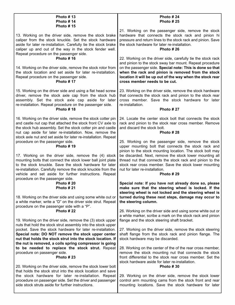
Photo # 13Photo # 14Photo # 15
13. Working on the driver side, remove the stock brakecaliper from the stock knuckle. Set the stock hardwareaside for later re-installation. Carefully tie the stock brakecaliper up and out of the way in the stock fender well.Repeat procedure on the passenger side.
Photo # 16
14. Working on the driver side, remove the stock rotor fromthe stock location and set aside for later re-installation.Repeat procedure on the passenger side.
Photo # 17
15. Working on the driver side and using a flat head screwdriver, remove the stock axle cap from the stock hubassembly. Set the stock axle cap aside for laterre-installation. Repeat procedure on the passenger side.
Photo # 18
16. Working on the driver side, remove the stock cotter pinand castle nut cap that attached the stock front CV axle tothe stock hub assembly. Set the stock cotter pin and castlenut cap aside for later re-installation. Now, remove thestock axle nut and set aside for later re-installation. Repeatprocedure on the passenger side.
Photo # 19
17. Working on the driver side, remove the (4) stockmounting bolts that connect the stock lower ball joint plateto the stock knuckle. Save the stock hardware for laterre-installation. Carefully remove the stock knuckle from thevehicle and set aside for further instructions. Repeatprocedure on the passenger side.
Photo # 20Photo # 21
18. Working on the driver side and using some white out ora white marker, write a “D” on the driver side strut. Repeatprocedure on the passenger side with a “P”.
Photo # 22
19. Working on the driver side, remove the (3) stock uppernuts that hold the stock strut assembly into the stock upperpocket. Save the stock hardware for later re-installation.Special note: DO NOT remove the stock upper centernut that holds the stock strut into the stock location. Ifthe nut is removed, a coils spring compressor is goingto be needed to replace the stock strut. Repeatprocedure on passenger side.
Photo # 23
20. Working on the driver side, remove the stock lower boltthat holds the stock strut into the stock location and savethe stock hardware for later re-installation. Repeatprocedure on passenger side. Set the driver and passengerside stock struts aside for further instructions.
Photo # 24Photo # 25
21. Working on the passenger side, remove the stockhardware that connects the stock rack and pinion hipressure and return lines to the stock rack and pinion. Savethe stock hardware for later re-installation.
Photo # 26
22. Working on the driver side, carefully tie the stock rackand pinion to the stock sway bar mount. Repeat procedureon the passenger side. Special note: This is done so thatwhen the rack and pinion is removed from the stocklocation it will be up out of the way when the stock rearcross member needs to be cut.
23. Working on the driver side, remove the stock hardwarethat connects the stock rack and pinion to the stock rearcross member. Save the stock hardware for laterre-installation.
Photo # 27
24. Locate the center stock bolt that connects the stockrack and pinion to the stock rear cross member. Removeand discard the stock bolt.
Photo # 28
25. Working on the passenger side, remove the stockupper mounting bolt that connects the stock rack andpinion to the stock mounting location. The stock bolt maybe discarded. Next, remove the stock lower mounting allthread nut that connects the stock rack and pinion to thestock rear cross member. Save the stock lower mountingnut for later re-installation.
Photo # 29
Special note: If you have not already done so, pleasemake sure that the steering wheel is locked. If thesteering wheel is not locked and the steering wheel isturned during these next steps, damage may occur tothe steering column.
26. Working on the driver side and using some white out ora white marker, scribe a mark on the stock rack and pinionflange and the stock steering shaft bracket.
27. Working on the driver side, remove the stock steeringshaft flange from the stock rack and pinion flange. Thestock hardware may be discarded.
28. Working on the center of the of the rear cross member,remove the stock mounting nut that connects the stockfront differential to the stock rear cross member. Set thestock hardware aside for later re-installation.
Photo # 30
29. Working on the driver side, remove the stock lowercontrol arm mounting cams from the stock front and rearmounting locations. Save the stock hardware for later

re-installation. Set the stock lower control arms aside forlater re-installation. Repeat procedure on the passengerside.
Photo # 31
30. Working on the driver side, measure from the stock rearlower control arm mounting point towards the inside of thevehicle 3 1/4”. Scribe a mark on the stock rear crossmember. Using a suitable cutting tool, carefully cut thestock rear cross member. Special note: Tuff Countrydoes not recommend using a torch when making thiscut. Tuff Country recommends using a sawzall to makethis cut. Also, take special care not to cut any lines,hoses or wires.
Photo # 32
31. Working on the passenger side, measure from thestock rear lower control arm mounting point towards theinside of the vehicle 5 3/4”. Scribe a mark on the stock rearcross member. Using a suitable cutting tool, carefully cutthe stock rear cross member. Special note: Tuff Countrydoes not recommend using a torch when making thiscut. Tuff Country recommends using a sawzall to makethis cut. Also, take special care not to cut any lines,hoses or wires. The stock rear cross member that wascut out may be discarded.
Photo # 33Photo # 34
32. Place a hydraulic floor jack under the front differentialand carefully raise up on the hydraulic floor jack until itmakes contact with the front differential.
33. Working on the driver side, remove the stock mountinghardware that connects the stock driver side differentialbracket to the stock front cross member. Save the stockhardware for later re-installation. Repeat procedure on thepassenger side.
Photo # 35
34. Working on the driver side, remove the (3) stock boltsthat connect the driver side differential bracket to the stockfront differential. Save the stock hardware for laterre-installation. Repeat procedure on the passenger side.Special note: On the passenger side, the stockdifferential bracket is attached to the stock frontdifferential with (2) stock bolts.
Photo # 36Photo # 37
35. With a tie down strap, carefully tie the stock frontdifferential to the stock frame rail. This is done so the frontdifferential will hang. With the front differential hanging,remove the hydraulic floor jack from under the frontdifferential.
Photo # 38
36. Locate the new driver and passenger side differentialrelocation brackets. Locate (4) PB2408 poly bushings and
(2) S10082 sleeves from hardware bag 55906NB1. Installthe new poly bushings into the new driver and passengerside differential relocation brackets. Next, install the newsleeves into the newly installed poly bushings. Specialnote: Make sure to use a lithium or moly base greaseprior to inserting the new bushings into the new driverand passenger side differential relocation brackets.This will increase the life of the bushings as well asprevent squeaking.
37. Locate the new driver side differential relocationbracket. Locate the (3) stock mounting bolts that wereremoved in step # 34. Also, locate (3) 9/16” USS flatwashers from hardware bag 55907NB. Working on thedriver side, install the new driver side differential relocationbracket to the stock front differential and secure using thestock mounting bolts and the new 9/16” USS flat washers.Do not tighten at this point.
Photo # 39
38. Locate the new passenger side differential relocationbracket. Locate the (2) stock mounting bolts that wereremoved in step # 34. Also locate (2) 9/16” USS flatwashers from hardware bag 55907NB. Working on thepassenger side, install the new passenger side differentialrelocation bracket to the stock front differential and secureusing the stock mounting bolts and the new 9/16” USS flatwashers. Do not tighten at this point.
Photo # 40
39. Locate the stock driver and passenger side mountinghardware that attached the stock differential brackets to thestock front cross member that were removed in step # 33.Working on the driver side, install the new driver sidedifferential relocation bracket to the stock front crossmember using the stock hardware. Do not tighten at thispoint. Repeat procedure on the passenger side.
40. Locate (2) 3/4” x 5 1/2” bolts, (2) 3/4” x 5” bolts, (8) 3/4”flat washers and (4) 3/4” unitorque nuts from hardware bag55907NB. Also, locate the new one piece lower sub frame.Install the new one piece lower sub frame into the stockfront and rear lower control arm pockets and secure usingthe new 3/4” x 5 1/2” bolts into the front location and thenew 3/4” x 5” bolts and hardware into the rear location.Special note: Do not tighten at this point. Also, wheninstalling the new one piece lower sub frame, makesure that the rear mounting stud on the rear portion ofthe front differential seats properly into the new onepiece lower sub frame.
Photo # 41
41. Locate (1) 1/2” x 1 1/2” bolt, (2) 7/16” USS flat washers,and (1) 1/2” unitorque nut from hardware bag 55907NB.Working on the driver side, install the newly installed onepiece lower sub frame to the newly installed driver sidedifferential relocation bracket and secure using the new1/2” x 1 1/2” bolt and hardware. Special note: Do nottighten at this point. Also, when installing the new

driver side differential relocation bracket to the newone piece lower sub frame, make sure that the newdriver side differential relocation bracket is installedtowards the inside of the new differential tabs on thenew one piece lower sub frame.
Photo # 42
42. Locate (1) 1/2” x 1 1/2” bolt, (2) 7/16” USS flat washers,and (1) 1/2” unitorque nut from hardware bag 55907NB.Working on the passenger side, install the newly installedone piece lower sub frame to the newly installed passengerside differential relocation bracket and secure using thenew 1/2” x 1 1/2” bolt and hardware. Special note: Do nottighten at this point. Also, when installing the newpassenger side differential relocation bracket to thenew one piece lower sub frame, make sure that the newpassenger side differential relocation bracket isinstalled towards the inside of the new differential tabson the new one piece lower sub frame.
Photo # 43
43. Locate the stock mounting hardware that was removedin step # 28. Secure the rear mounting stud on the rearportion of the front differential to the new one piece lowersub frame using the stock hardware. Do not tighten at thispoint.
44. Move back to the newly installed 3/4” x 5” bolts and 3/4”x 5 1/2” bolts securing the new one piece lower sub frameinto the new location and add some thread locker or locktite. Torque the new 3/4” bolts and hardware to 125 ft lbs.
Photo # 44
45. Move back to the (3) stock bolts holding the newlyinstalled driver side differential relocation bracket to thestock front differential and add some thread locker or locktite. Torque to 85 ft lbs. Repeat procedure on thepassenger side.
Photo # 45
46. Move back to the new 1/2” x 1 1/2” bolts holding thenewly installed driver side differential relocation bracket tothe tab on the newly installed one piece sub frame and addsome thread locker or lock tite. Torque to 75 ft lbs. Repeatprocedure on the passenger side.
Photo # 46
47. Move back to the stock hardware holding the newlyinstalled driver side differential relocation bracket to thestock front cross member and add some thread locker orlock tite. Torque to 85 ft lbs. Repeat procedure on thepassenger side.
Photo # 47
48. Move back to the rear mounting stud on the rearportion of the front differential and add some thread lockeror lock tite. Torque to 75 ft lbs.
Photo # 48
49. It is now ok to remove the tie down strap holding thestock front differential to the stock frame rail.
50. Locate the stock lower control arm mounting cams andthe stock lower control arms that were removed in step #29. Working on the driver side, install the stock lowercontrol arm to the newly installed one piece lower subframe using the stock cams. Do not tighten at this point.Repeat procedure on the passenger side.
Photo # 49
51. Working on the driver side of the stock rack and pinion,remove the stock rubber bushing and discard.
Photo # 50
52. Working on the center of the stock rack and pinion,remove the stock rubber bushing and discard.
Photo # 51
53. Locate (2) new MO3354 poly bushings and (1) S10075sleeve from hardware bag 55906NB1. Working on thecenter of the stock rack and pinion, install the new bushingsand sleeves into the stock rack and pinion. Special note:Make sure to use a lithium or moly base grease prior toinserting the new bushings into the stock rack andpinion. This will increase the life of the bushings aswell as prevent squeaking.
Photo # 52
54. Locate (2) MO2382 poly bushings and (1) S10076sleeve from hardware bag 55906NB1. Working on thedriver side of the stock rack and pinion, install the newbushings and sleeves into the stock rack and pinion.Special note: Make sure to use a lithium or moly basegrease prior to inserting the new bushings into thestock rack and pinion. This will increase the life of thebushings as well as prevent squeaking.
Photo # 53Photo # 54
55. Working on the driver side stock sway bar mountingbracket attached to the inside part of the stock frame railand using a tape measure, measure from the top leadingedge of the front portion of the bracket downward 1 1/2”.Using some white out or a white marker, scribe a line. Nowmeasure from the inside leading edge towards the stockframe rail 1”. Using some white out or a white marker,scribe a line.
Photo # 55
56. Using a die grinder, carefully cut out the front portion ofthe stock sway bar mount. Special note: Tuff Countrydoes not recommend using a torch when making thiscut. Tuff Country recommends using a die grinder tomake this cut. The stock gas line runs on the inside ofthe stock frame rail, take special care not to cut thestock gas lines. Also when making this cut, take spe-cial care not to cut into the stock frame rail. Clean upany exposed slag from the trimming performed in this

installation step.Photo # 56Photo # 57Photo # 58
57. Locate the new steering shaft extension bracket. Alsolocate (2) 3/8” x 1” bolts, (4) 5/16” USS flat washers and (2)3/8” unitorque nuts from hardware bag 55907NB. Install thenew steering shaft extension bracket to the stock steeringshaft using the new 3/8” x 1” bolts and hardware. Do nottighten at this point.
58. Locate the new passenger side rack and pinion supportbracket. Working on the passenger side, install the newpassenger side rack and pinion support bracket to thestock rack and pinion bolt.
Photo # 59
59. Locate the stock driver side rack and pinion mountinghardware that was removed in step # 23. Also, locate (2)S10077 over size washers from hardware bag 55906NB1.Working on the driver side, install the stock rack and pinionto the driver side of the newly installed one piece sub frameand secure using the stock hardware and the new over sizewashers. Do not tighten at this point. Special note:make sure to install one of the over size washersbetween the stock rack and pinion and the one piecesub frame.
60. Locate the center rack and pinion bracket. Locate (1)9/16” x 2 1/2” bolts, (1) 9/16” lock washer, (1) 1/2” USS flatwasher, (2) 1/2” x 1 1/2” bolts, (4) 7/16” USS flat washersand (2) 1/2” unitorque nuts from hardware bag 55907NB.Also, locate (2) S10140 (9/16” fender washers) fromhardware bag 55906NB1. Working on the center of thenewly installed sub frame, install the center rack and pinionbracket to the sub frame and secure using the new 1/2” x 11/2” bolts and hardware. Special note: make sure toinstall the bracket with the weld on the spud towardsthe ground. Do not tighten at this point. Next, install thestock rack and pinion to the new center rack and pinionbracket using the new 9/16” x 2 1/2” bolts, hardware and9/16” fender washers. Special note: The fender washersneed to be installed on top of the stock rack and pinionand between the stock rack and pinion and the newcenter rack and pinion bracket. Do not tighten at thistime. Special note: The bolt will be installed from thetop of the rack and pinion downward.
61. Locate the stock passenger side rack and pinion allthread nut that was removed in step # 25. Also, locate (1)9/16” x 2 1/2” bolt, (1) 9/16” lock washer from hardware bag55907NB. Remove and re-install the stock rack and pinionmounting bracket in the upside down position around thestock rack and pinion bushing. Secure the upper part of thestock rack and pinion bracket to the stock bolt and secureusing the stock all thread nut. Do not tighten at this point.Secure the bottom part of the stock bracket to the newlyinstalled one piece sub frame using the new 9/16” x 2 1/2”
bolt and hardware. Do not tighten at this point.Photo # 60Photo # 61
62. Locate (1) BLR09 (relocation bracket) from hardwarebag 55906NB1. Locate (1) 5/16” x 1” bolt, (2) 1/4” USS flatwashers and (1) 5/16” unitorque nut from hardware bag55907NB. Also, locate the stock rack and pinion hipressure line mounting hardware that was removed in step# 21. Install the new relocation bracket to the stock rackand pinion hi pressure lines and secure using the new 5/16”x 1” bolt and hardware. Do not tighten at this point. Nextsecure the previously installed relocation bracket to thestock rack and pinion and secure using the stock hardware.Make sure to use thread lock or lock tite and torque to 12ft lbs. Move back to the new 5/16” x 1” bolt installedearlier in this step and add some thread locker or lock titeand torque the new 5/16” x 1” bolt to 14 ft lbs.
Photo # 62
63. Locate (2) 3/8” x 1” bolts, (4) 5/16” USS flat washersand (2) 3/8” unitorque nuts from hardware bag 55906NB1.Install the newly installed steering shaft extension bracketto the stock rack and pinion flange and secure using thenew 3/8” x 1” bolts and hardware. Add some thread lockeror lock tite to the new bolts and torque to 18 ft lbs. Specialnote: make sure that the marks that were scribed instep # 26 line up with each other.
64. Move back to the stock driver side bolt holding thestock rack and pinion to the new sub frame and add somethread locker or lock tite and torque to 110 ft lbs. Moveback to the passenger side rack and pinion and add sometread locker or lock tite to the stock all thread nut and thenew 9/16” x 2 1/2” bolt and torque both to 85 ft lbs. Moveto the center rack and pinion bracket attached to the newsub frame and add some thread locker or lock tite to the1/2” x 1 1/2” bolt and torque to 65 ft lbs. Now move backto the 9/16” x 2 1/2” bolt holding the stock rack and pinionto the new center rack and pinion bracket and torque to 85ft lbs.
Special note: During the installation of the stock hubassembly to the new knuckles, special care needs tobe taken not to damage the hub assembly or knuckle.We need to make sure that we press the knuckle ontothe hub assembly NOT THE HUB ASSEMBLY ONTOTHE KNUCKLE. If you have any questions, please callthe Tech Department @ Tuff Country. (801) 280 - 2777
65. Locate the stock driver side knuckle that was removedfrom step # 17. Working on the stock driver side knuckle,carefully remove the inner stock oil seal from the stockknuckle. Special Note: Take special care not to damagethe stock oil seal during removal. Set the stock oil sealaside for later instructions.
Photo # 63Photo # 64

66. Working on the stock driver side knuckle, carefullypress out the stock hub assembly from the stock knuckle.Special Note: Tuff Country highly recommends thatthis step be performed by a capable installer ortechnician. If special care is not taken, the stock hubassembly, ABS speed sensor rotor or bearing spacermay be damaged. If the stock hub assembly, ABSspeed sensor rotor or bearing spacer are damaged anew hub assembly, ABS speed sensor or bearingspacer will need to be purchased from your localdealer. Once the stock hub assembly has been pressedout, set the stock hub assembly, ABS speed sensor rotorand bearing spacer aside for later instructions.
Photo # 65Photo # 66
67. Working on the stock driver side knuckle, remove the(4) stock bolts holding the stock dust cover to the stockdriver side knuckle. Set the stock bolts and dust coveraside for later instructions. Also, at this time remove theouter stock oil seal from the stock knuckle. Special note:Take special care not to damage the stock oil sealduring removal. Set the stock oil seal aside for laterinstructions. The stock knuckle may be discarded.
Photo # 67Photo # 68Photo # 69Photo # 70
68. Locate the new driver side knuckle. Locate the stockouter oil seal, the (4) stock bolts and the stock dust coverthat were removed in step # 67. Install the stock outer oilseal to the new knuckle. Special note: Take special carenot to damage the stock oil seal during installation.Next, install the stock dust cover to the new driver sideknuckle using the stock hardware. Special note: Makesure to use thread locker or lock tite. Torque the stockhardware to 13 ft lbs.
Photo # 71Photo # 72
69. Locate the stock hub assembly, the stock ABS speedsensor rotor and bearing spacer that were removed fromstep # 66. Carefully press the new knuckle onto thestock hub assembly. Special note: Tuff Country highlyrecommends that this step be performed by a capableinstaller or technician. If special care is not taken, thestock hub assembly or new driver side knuckle may bedamaged. If the stock hub assembly or the new driverside knuckle are damaged, new parts will need to bepurchased. Re-install the stock ABS speed sensor andbearing spacer into the new driver side knuckle. Specialnote: Tuff Country highly recommends that this step beperformed by a capable installer or technician. Ifspecial care is not taken, the stock ABS speed sensoror bearing spacer may be damaged. If the stock ABSspeed sensor rotor or bearing spacer are damaged,new ABS speed sensor rotor or bearing spacer willneed to purchased.
Photo # 73 / Photo # 74Photo # 75 / Photo # 76
Photo # 77
70. Locate the stock inner oil seal that was removed fromstep # 65. Carefully re-install the stock inner oil seal to thenew driver side knuckle. Special note: Take special carenot to damage the stock oil seal during installation. Setthe new driver side knuckle aside for laterre-installation.
Photo # 78Photo # 79
71. Repeat steps 65 — 70 for the passenger sideknuckle.
72. Locate (1) wire tie from hardware bag 55907NB1.Locate the new driver side knuckle. Remove the new upperball joint castle nut and set aside for later installation. Installthe wire tie around the new upper ball joint dust boot on thenew driver side knuckle. Working on the driver side,carefully slide the stock drive shaft into the new driver sideknuckle. Secure the new driver side knuckle to the stockupper control arm and finger tighten the new upper ball jointcastle nut that was removed earlier in this step.
Photo # 80Photo # 81
73. Locate the (4) stock bolts that connected the stocklower control arm ball joint plate to the stock knuckle thatwere removed from step # 17. Secure the stock lowercontrol arm ball joint plate to the new driver side knuckleusing the stock hardware. Make sure to use threadlocker or lock tite. Torque to 39 ft lbs.
Photo # 82
74. Locate (1) new cotter pin from hardware bag55906NB1. Working on the driver side, torque the newupper castle nut that connects the upper ball joint to thestock driver side upper control arm to 80 ft lbs. Makingsure that the hole in the new castle nut and the new upperball joint are lined up, install the new cotter pin. Specialnote: If the new cotter pin can not be installed becausethe hole in the new castle nut does not line up with thenew ball joint, DO NOT loosen the new castle nut sothat the cotter pin can fit, tighten the new castle nutsome more so that the new cotter pin can be installed.
Photo # 83Photo # 84
75. Locate the stock cotter pin, stock lock cap and the stockaxle nut that was removed in step # 16. Working on thedriver side, secure the stock drive shaft to the stock hubassembly using the stock nut. Special note: Make sure touse thread locker or lock tite. Torque to 174 ft lbs. Next,install the stock lock cap and the stock cotter pin.
Photo # 85Photo # 86Photo # 87

76. Locate the stock grease cap that was removed in step# 15. Working on the driver side, re-install the stock greasecap into the stock location.
Photo # 88
77. Repeat steps 72 — 76 for the passenger sideknuckle.
78. Locate the new driver and passenger side sway barrelocation brackets. Also, locate (4) 3/8” x 1 1/4” bolts, (8)5/16” USS flat washers and (4) 3/8” unitorque nuts fromhardware bag 55907NB. Working on the driver side, installthe new driver side sway bar relocation bracket to the stockframe mount location and secure using the new 3/8” x 11/4” bolts and hardware. Special note: Do not tighten atthis point. Repeat procedure on the passenger side.
Photo # 89
79. Locate the stock sway bar and the stock hardware thatwas removed from step # 5. Working on the driver side,install the stock sway bar to the newly installed sway barrelocation bracket and secure using the stock hardware.Do not tighten at this point. Repeat procedure on thepassenger side.
Photo # 90
80. Locate the stock sway bar end link hardware and thestock sway bar end links that were removed from steps # 3& 4. Working on the driver side, install the stock sway barto the stock lower control arm using the stock hardware.Make sure to use thread locker or lock tite. Torque to 22ft lbs. Next secure the stock end link to the stock sway barand secure using the stock hardware. Make sure to usethread locker or lock tite and torque to 22 ft lbs. Repeatprocedure on the passenger side.
Photo # 91
81. Working on the driver side, add some thread locker orlock tite to the new hardware attaching the new sway barrelocation bracket to the stock location and torque to 24 ftlbs. Now add some thread locker or lock tite to the stockhardware that is attaching the stock sway bar to the newlyinstalled sway bar relocation bracket and torque to 18 ftlbs.
82. Locate the stock rotors that were removed from step #14. Working on the driver side, re-install the stock rotor tothe stock hub assembly. Repeat procedure on thepassenger side.
Photo # 92
83. Locate the stock hardware that attached the stockbrake caliper to the stock knuckle that was removed fromstep # 13. Working on the driver side, carefully untie thestock brake caliper that was tied in the stock fender welland attach the stock brake caliper to the new driver sideknuckle. Special note: Make sure to use thread lockeror lock tite. Torque to 90 ft lbs. Repeat procedure on thepassenger side.
Photo # 93Photo # 94
84. Locate the stock brake line bracket and hardware thatwas attached to the stock knuckle that was removed in step# 8. Working on the driver side, attach the stock brake linebracket to the newly installed knuckle using the stockhardware. Special note: Make sure to use thread lockerof lock tite. Torque to 10 ft lbs. Repeat procedure on thepassenger side.
Photo # 95
85. Locate the stock ABS line hardware that connected thestock ABS line to the stock knuckle that was removed fromstep # 7. Working on the driver side, attach the stock ABSline to the newly installed knuckle using the stockhardware. Special note: Make sure to use thread lockeror lock tite. Torque to 71 in lbs. Repeat procedure on thepassenger side. Special note: If the vehicle that you areworking on is equipped without ABS front brakes, (2)of part # 54900-13 (ABS plugs for new knuckles) needto be purchased as a separate part #. If you have notalready ordered the new ABS plugs, please feel free tocontact Tuff Country or your local Tuff Country dealerand order the new ABS plugs. If these parts are notinstalled to the new knuckles, damage will occur to thestock hub assembly and Tuff Country will not be liablefor damages.
Photo # 96Photo # 97
86. Working on the driver side, attach the stock ABS lineclip into the stock brake line bracket that attaches to theback side of the newly installed driver side knuckle. Repeatprocedure on the passenger side.
Photo # 98
87. Locate (2) front brake line relocation brackets fromhardware bag 55906NB1. Locate (2) 5/16” x 3/4” bolts, (4)1/4” USS flat washers and (2) 5/16” unitorque nuts fromhardware bag 55907NB. Also, locate the stock brake linebracket hardware that was removed in step # 11. Workingon the driver side, attach the new brake line relocationbracket to the stock location and secure using the stockhardware. Do not tighten at this point. Now attach thestock brake line bracket to the newly installed brake linerelocation bracket using the new 5/16” x 3/4” bolt andhardware. Make sure to use thread locker or lock tite andtorque to 14 ft lbs. Add some thread locker or lock tite tothe stock bolt holding the new brake line relocation bracketto the stock location and torque to 12 ft lbs. Repeatprocedure on the passenger side.
Photo # 99
88. Locate the (2) shock ties from hardware bag55906NB1. Working on the driver side, tie the stock brakeline bracket and the stock ABS lines together. Cut off theexcess part of the shock tie. Repeat procedure on thepassenger side.

Photo # 100
89. Locate (2) new front upper strut spacers. Locate thestock hardware that connected the stock strut into the stocklocation that was removed from step # 19. Locate the stockdriver side strut that was removed in step # 20. Working onthe driver side strut, install the new front upper strut spacerto the stock strut using the stock hardware. Special note:Make sure to use thread locker or lock tite. Torque to38 ft lbs. Repeat procedure on the passenger side strut.
Photo # 101
90. Locate (6) 3/8” nylock nuts, (6) 5/16” flat washers and(6) 3/8” lock washers from hardware bag 55907NB.Working on the driver side, install the stock driver side strutinto the stock upper location, secure using the new 3/8”hardware. Special note: Make sure to use thread lockeror lock tite. Torque to 38 ft lbs. Also, make sure thatyou install the driver side strut on the driver side of thevehicle and the same goes for the passenger side strut.Refer to the markings that were made in step # 18.Repeat procedure on passenger side.
Photo # 102
91. Locate the stock lower hardware that attached thestock strut to the stock lower control arm that was removedfrom step # 20. Working on the driver side, install the lowereyelet of the stock strut into the stock location using thestock hardware. Special Note: Make sure to use threadlocker or lock tite. Torque to 85 ft lbs. Repeat procedureon the passenger side.
Photo # 103
92. Working on the driver side, remove the stock frontbump stop from the stock location. Save the stock bumpstop for later re-installation. Repeat procedure on thedriver side rear bump stop. Repeat procedure on thepassenger side.
Photo # 104
93. Locate (4) new bump stop relocation brackets. Locate(4) 10 mm flat washers, (4) 10 mm lock washers and (4) 10mm x 25 mm fine bolts from hardware bag 55907NB.Working on the driver side, install the new bump stoprelocation brackets to the stock front and rear location andsecure using the new 10 mm x 25 mm fine bolts andhardware. Make sure to use thread locker or lock tite andtorque to 28 ft lbs. Repeat procedure on the passengerside.
Photo # 105
94. Locate (4) 10 mm fine nuts, (4) 10 mm flat washers and(4) 10 mm lock washers from hardware bag 55907NB.Also, locate the stock front and rear bump stops that wereremoved in step # 92. Working on the driver side, install thestock front and rear bump stops to the newly installed frontand rear bump stop relocation brackets and secure usingthe new 10 mm hardware. Make sure to use thread lockeror lock tite and torque to 28 ft lbs. Repeat procedure on the
passenger side.Photo # 106
95. Locate the stock skid plate that was removed in step #2. Place the stock skid plate flat on a work bench. Workingon the driver side of the stock skid plate and referring toPhoto # 107 measure from the leading edge of the stockskid plate towards the back of the stock skid plate 1 1/4”and scribe a mark with white out or a white marker. Nowreferring to Photo # 108 measure 1 1/2” from the leadingedge towards the inside of the vehicle and scribe a mark.Repeat procedure on the passenger side of the stock fromskid plate. With a suitable cutting tool, carefully notch outthe stock skid plate on the lines that were scribed earlier inthis step.
Photo # 107Photo # 108
96. Locate the stock skid plate hardware that was removedin step # 2. Install the stock skid plate into the stocklocation and secure using the stock hardware. Make sureto use thread locker or lock tite and torque to 18 ft lbs.
Photo # 109
97. Locate the stock rack and pinion outer ball joint cotterpin and nut that was removed in step # 6. Working on thedriver side, install the stock rack and pinion outer ball jointto the stock lower ball joint plate and secure using the stocknut. Torque to 75 ft lbs. Making sure that the holes in thestock castle nut and the stock rack and pinion outer balljoint lined up, install the stock cotter pin. Special note: Ifthe stock cotter pin can not be installed because thehole in the stock castle nut does not line up with thestock rack and pinion ball joint, DO NOT loosen thestock castle nut so that the cotter pin can fit, tightenthe stock castle nut some more so that the stockcotter pin can be installed. Repeat procedure on thepassenger side.
Photo # 110
98. Install the tires and wheels and carefully lower thevehicle to the ground.
99. With the weight of the vehicle on the ground, workingon the driver side, torque the stock cam bolts that attachthe stock front lower control arm to the newly installed onepiece lower sub frame to 96 ft lbs. Repeat procedure onthe passenger side.
100. Check and double check to make sure that all stepswere performed properly. And then check them again.
Front End Installation Complete:
Rear End Installation:
101. To begin installation, block the front tires of the vehicleso that the vehicle is stable and can’t roll forward. Safely liftthe rear of the vehicle and support the frame with a pair of

jack stands. Place a jack stand on both the driver andpassenger side. Next, remove the rear wheels and tiresfrom both sides.
102. Using a pair of hydraulic floor jacks, place onehydraulic floor jack on the driver side of the rear axle andone on the passenger side.
103. Working on the driver side, remove the stock shockfrom the stock upper and lower location. The stock shockand the stock upper hardware may be discarded. Save thestock lower hardware for later re-installation. Special Note:New longer rear shocks are needed, if you have notalready ordered your new rear shocks, please contactTuff Country or your local Tuff Country dealer andorder the proper shocks. Tuff Country recommendsusing a 26” fully extended nitrogen gas shock. Repeatprocedure on passenger side.
104. Working on the passenger side of the rear axle,remove the stock brake proportioning valve bracket fromthe stock location and save the stock hardware for laterre-installation.
Photo # 111
105. Working on the driver side, remove the stockemergency brake cable bracket from the bottom of thestock frame rail. Save the stock hardware for laterre-installation.
Photo # 112
106. Locate the new rear brake line. Remove the stock rearbrake line from the stock upper and lower location. Thestock upper brake line clip and the stock brake line may bediscarded. Special note: Brake fluid will drain out, soplace something under the vehicle to catch the fluid asit drains out. For now, install the new brake line to thestock upper and lower location and just hand tighten. Thiswill help eliminate some brake fluid from draining out.
107. With a hammer, carefully hit the stock upper brake linebracket that is attached to the stock rear cross member. Hitwith a hammer until the bracket is pointing directly down.
Photo # 113Photo # 114
108. Locate (1) new S10137, rear brake line bracket, fromhardware bag 55906NB1. Using a pair of vise grips, clampthe new brake line bracket to the stock brake line bracket.
Photo # 115
109. Locate (1) new S10138, 1/4” x 3/4” self tapping screwfrom hardware bag 55906NB1. Using a 1/8” drill bit andusing the new brake line bracket as a guide, carefully drilla 1/8” hole into the stock brake line bracket. Now install thenew 1/4” x 3/4” self tapping screw to secure the new brakeline bracket to the stock brake line bracket. Remove thepair of vise grips.
Photo # 116
110. Remove the new brake line from the stock hard mountand install the new brake line and hard mount backtogether at the new brake line bracket. Torque to 26 ft lbs.Now torque to bottom mount of the new brake line to thestock bottom mount to 26 ft lbs.
Photo # 117
111. Locate (1) new e-clip from hardware bag 55906NB1.Install the new e-clip into the stock location.
Photo # 118
112. Working on the driver side, remove the stock u-boltsfrom the stock location and discard the stock u-bolts andu-bolt hardware. Set the stock upper bump stop and loweru-bolt plate aside for later re-installation. Repeat procedureon the passenger side.
113. Carefully lower down on both hydraulic floor jacks atthe same time approximately 4.5”. Take special care not tokink on over extend any brake lines and/or hoses.
114. Locate (2) new 4” lifted blocks. Working on the driverside, install the new 4” lifted block between the stock springassembly and the stock axle. Special note: The new 4”lifted block has a slight taper to it, make sure that whenyou install the new block that you install it with thetaper going towards the front of the vehicle. Repeatprocedure on the passenger side.
115. Carefully raise up on both hydraulic floor jacks at thesame time until the new 4” lifted rear blocks seat properlyto the stock rear springs.
116. Locate (4) 9/16” x 2 9/16” x 10 5/8” square u-bolts.Locate the (8) new 9/16” u-bolt high nuts and (8) new u-boltharden washers from hardware bag 916NW. Also, locatethe stock upper bump stops and the stock lower u-boltplates that removed in step # 112. Working on the driverside, install the stock upper bump stop, lower u-bolt plateand the new u-bolts into the stock location and secureusing the new high nuts and harden u-bolt washers. Torqueto 115 ft lbs. Repeat procedure on the passenger side.
Photo # 119
117. Carefully remove both hydraulic floor jacks from underthe vehicle.
118. Locate (1) new rear brake proportioning valve bracket.Also, locate the stock rear brake proportioning valvebracket hardware that was removed in step # 104. Installthe new rear brake proportioning valve bracket to the stocklocation using the stock hardware. Make sure to usethread locker or lock tite and torque to 12 ft lbs.
Photo # 120
119. Locate the stock emergency brake cable brackethardware that was removed in step # 105. Also, locate (1)new BLR09 from hardware bag 55906NB1. Install the newBLR09 to the bottom side of the stock frame rail and secure

using the stock hardware. Make sure to use thread lockeror lock tite and torque to 12 ft. lbs.
120. Locate (1) 5/16” x 1” bolt, (2) 1/4” USS flat washersand (1) 5/16” unitorque nut from hardware bag 55907NB.Install the stock emergency brake line bracket to the newlyinstalled BLR09 and secure using the new 5/16” x 1” boltand hardware. Make sure to use thread locker or lock titeand torque to 18 ft. lbs.
Photo # 121
121. Locate (2) 5/16” x 1” bolts, (4) 1/4” flat washers and (2)5/16” unitorque nuts from hardware bag 55907NB. Installthe stock rear brake proportioning valve bracket to thenewly installed rear brake proportioning valve bracket usingthe new 5/16” x 1” bolts and hardware. Special Note:Make sure to use thread locker or lock tite and torqueto 18 ft lbs.
Photo # 122
122. Locate the new rear shocks. Special Note: Newlonger rear shocks are needed once this suspensionsystem has been instead and the new rear shocksneed to be ordered as a separate part #. If you have notalready ordered your new rear shock, please contactTuff Country or your local Tuff Country dealer andorder your new rear shocks. Tuff Country recommendsusing a 26” fully extended nitrogen gas shock in therear of your vehicle. Locate (4) new S10107 over sizewashers from hardware bag 55907NB. Also, locate (4)PB8297 front upper shock bushings from 55906NB1. Installthe new bushings and proper sleeves into the lower eyeletof your new shocks. Special note: The new bushingsand sleeves are supplied with your new shocks. Also,make sure to use a lithium or moly base grease prior toinserting the new bushings and sleeves into the newshocks. This will increase the life of the bushings andwill help prevent squeaking. Install the new shock bootsonto the new shocks. Special note: The new shock bootsare not included with this suspension system and thenew shock boots need to be ordered as a separate part#. If you have not already ordered your new shockboots, please feel free to contact Tuff Country or yourlocal Tuff Country dealer and order your new shockboots. Install the S10107 over size washer and uppershock bushing onto the stud of the new shocks. Working onthe driver side, install the new shock into the stock upperlocation, install the new upper shock bushing and new oversize washer and secure the new shock into the stock upperlocation using the new nut. Special note: The new uppershock nut is supplied with your new shocks. Do nottighten at this point. Repeat procedure on thepassenger side.
123. Locate the stock rear lower shock hardware that wasremoved in step # 103. Working on the driver side, installthe new shock into the stock lower location using the stockhardware. Torque the lower stock hardware to 65 ft lbs.and torque the stock upper nut to 18 ft lbs.
124. Re-install the tires and wheels and safely lower thevehicle to the ground.
125. With the new rear brake line being replaced, brakefluid drained out. Top of the brake fluid with the properbrake fluid and bleed the brakes. Refer to the ownersmanual for proper instruction on how to bleed the brakelines.
126. Check and double check to make sure that all stepswere performed properly. And then check them again.
Congratulations, installation complete!
Special note: After the completion of the installation,Tuff Country EZ-Ride Suspension recommends takingthe vehicle to an alignment shop and having a properfront end alignment performed.
Tuff Country EZ-Ride Suspension recommends that acomplete re-torque is done on all bolts associated withthis suspension system. It is the customersresponsibility to make sure that a re-torque isperformed on all hardware associated with thissuspension system after the first 100 miles ofinstallation. It is also the customers responsibility todo a complete re-torque after every 3000 miles or afterevery off road use. Neglect of following these stepscould cause brackets to come loose and cause seriousdamage to the suspension system and to the vehicle.
Tuff Country EZ-Ride Suspension packages (2) sets ofinstruction sheets with this box kit. (1) is for theinstaller and (1) is for the customer. The (1) for thecustomer has some post installation procedureliterature and it is the installers responsibility to makesure that the customer receives a copy of theinstallation manual along with the literature.
If you have any questions or concerns, please feel freeto contact Tuff Country or your local Tuff Countrydealer.

Photo # 1 Photo # 2
Photo # 3 Photo # 4
Photo # 5 Photo # 6

Photo # 7 Photo # 8
Photo # 9 Photo # 10
Photo # 11 Photo # 12

Photo # 13 Photo # 14
Photo # 15 Photo # 16
Photo # 17 Photo # 18
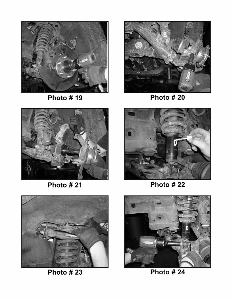
Photo # 19 Photo # 20
Photo # 21 Photo # 22
Photo # 23 Photo # 24

Photo # 25 Photo # 26
Photo # 27 Photo # 28
Photo # 29 Photo # 30

Photo # 31 Photo # 32
Photo # 33 Photo # 34
Photo # 35 Photo # 36

Photo # 37 Photo # 38
Photo # 39 Photo # 40
Photo # 41 Photo # 42

Photo # 43 Photo # 44
Photo # 45 Photo # 46
Photo # 47 Photo # 48

Photo # 49 Photo # 50
Photo # 51 Photo # 52
Photo # 53 Photo # 54

Photo # 55 Photo # 56
Photo # 57 Photo # 58
Photo # 59 Photo # 60

Photo # 61 Photo # 62
Photo # 63 Photo # 64
Photo # 65 Photo # 66

Photo # 67 Photo # 68
Photo # 69 Photo # 70
Photo # 71 Photo # 72

Photo # 73 Photo # 74
Photo # 75 Photo # 76
Photo # 77 Photo # 78

Photo # 79 Photo # 80
Photo # 81 Photo # 82
Photo # 83 Photo # 84

Photo # 85 Photo # 86
Photo # 87 Photo # 88
Photo # 89 Photo # 90

Photo # 91 Photo # 92
Photo # 93 Photo # 94
Photo # 95 Photo # 96

Photo # 97 Photo # 98
Photo # 99 Photo # 100
Photo # 101 Photo # 102

Photo # 103 Photo # 104
Photo # 105 Photo # 106
Photo # 107 Photo # 108

Photo # 109 Photo # 110
Photo # 111 Photo # 112
Photo # 113 Photo # 114

Photo # 115 Photo # 116
Photo # 117 Photo # 118
Photo # 119 Photo # 120

Photo # 121 Photo # 122
5900-01 (1)Driver side knuckle
5900-02 (1)Passenger side knuckle
55905-04 (2)Front upper strut spacers
TOYBRAKE-01 (1)Rear brake proportioning valve bracket
TOYDSDIFF-01 (1)DS differential relocation bracket
TOYDSSWAY-01 (1)DS sway bar relocation bracket
TOYPSDIFF-01 (1)PS differential relocation bracket
TOYPSSWAY-01 (1)PS sway bar relocation bracket

TOYSTEER-01 (1)Steering shaft extension bracket
TOYRACK-01 (1)Rack and Pinion support bracket
TOYSUB-01 (1)One piece lower sub frame
54800-06 (4)Bump stop relocation brackets
BLR01 (2)Relocation bracket
BLR09 (2)Relocation bracket
TOYRACK-02 (1)Center rack and pinion bracket