Embed Size (px)
Citation preview

PATENTED
BEFORE INSTALLING AND USING THE ACTUATOR, IT IS COMPULSORY FOR THE INSTALLER AND THE USER TO READ
AND UNDERSTAND THIS MANUAL IN ALL ITS PARTS.
THIS MANUAL IS INTEGRAL PART OF THE ACTUATOR AND MUST BE PRESERVED FOR FUTURE REFERENCE
UNTIL DEMOLITION OF THE SAME.
ACK4
INSTALLATION AND USE INSTRUCTIONS
CHAIN ACTUATOR FORWINDOW AUTOMATION
P/N 0P5101
VER.1.0 REV.07.04

3
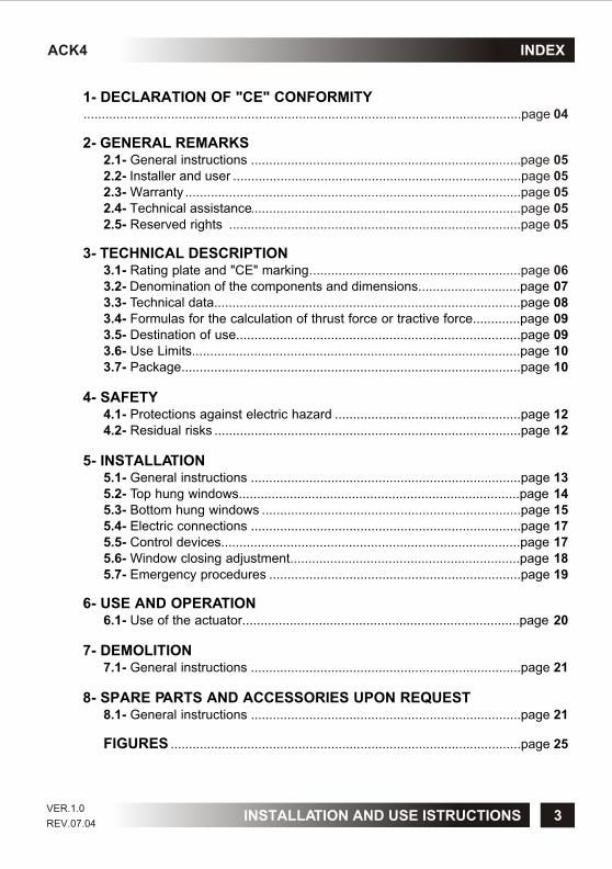
1- DECLARATION OF "CE" CONFORMITY
2- GENERAL REMARKS2.1- General instructions ..........................................................................2.2- Installer and user2.3- Warranty2.4- Technical assistance2.5- Reserved rights
3- TECHNICAL DESCRIPTION3.1- Rating plate and "CE" marking3.2- Denomination of the components and dimensions............................page 073.3- Technical data....................................................................................page 083.4- Formulas for the calculation of thrust force or tractive force.............page 093.5- Destination of use..............................................................................page 093.6- Use Limits..........................................................................................page 103.7- Package.............................................................................................page 10
4- SAFETY4.1- Protections against electric hazard ...................................................page 124.2- Residual risks ....................................................................................page 12
5- INSTALLATION5.1- General instructions ..........................................................................page 135.2- Top hung windows.............................................................................page 145.3- Bottom hung windows .......................................................................page 155.4- Electric connections ..........................................................................page 175.5- Control devices..................................................................................page 175.6- Window closing adjustment...............................................................page 185.7- Emergency procedures .....................................................................page 19
6- USE AND OPERATION6.1- Use of the actuator............................................................................page 20
7- DEMOLITION7.1- General instructions ..........................................................................page 21
8- SPARE PARTS AND ACCESSORIES UPON REQUEST8.1- General instructions ..........................................................................page 21
FIGURES ................................................................................................page 25
........................................................................................................................page 04
page 05...............................................................................page 05
............................................................................................page 05..........................................................................page 05
................................................................................page 05
..........................................................page 06
INDEXACK4
INSTALLATION AND USE ISTRUCTIONSVER.1.0
REV.07.04

TOPP SPA - Via Galvani, 59
36066 SANDRIGO (VI) - ITALIA
Tel. +39 0444 656700
Fax +39 0444 656701
Declares that the electric device
Called:
Type: ACK4 Models: ACK42 - ACK44
Serial No.: see data plate and CE marking applied on the equipment
Year of manufacture: 2004
complies with the requirements of the following directives:
73/23/EEC
(Low Voltage Directive: electrical equipment destined to be used within given voltage limits)
89/336/EEC
(Electromagnetic Compatibility Directive - on the approximation of the laws of the Member States relating to electromagnetic compatibility)
and, besides, it declares that the following harmonized standards have been applied:
EN60335-1:1994; EN60335-1/Ec:1995; EN60335-1/A11:1995
EN60335-1/A1:1996; EN60335-1/A13:1998; EN60335-1:A14:1998
EN60335-1/A15:2000;EN60335-1/A2:2000; EN60335-1/A16:2001
EN55014-1(2000) + EN55014-1/A1(2001) + EN55014-1/A2(2002);
EN61000-3-2 (2000) ; EN61000-3-3 (1995); EN61000-3-3/A1 (2001)
EN55014-2 (1997) + EN55014-2/A1 (2001)
Date: 07/01/2004
Surname and name: Matteo Cavalcante
Signature:……………………………………………...
CHAIN ACTUATOR FOR WINDOW AUTOMATION
4
1- DECLARATION OF "CE" CONFORMITY ACK4
INSTALLATION AND USE ISTRUCTIONSVER.1.0
REV.07.04
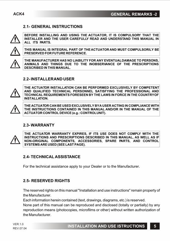
2.1- GENERAL INSTRUCTIONS
BEFORE INSTALLING AND USING THE ACTUATOR, IT IS COMPULSORY THAT THE INSTALLER AND THE USER CAREFULLY READ AND UNDERSTAND THIS MANUAL IN ALL ITS PARTS.
THIS MANUAL IS INTEGRAL PART OF THE ACTUATOR AND MUST COMPULSORILY BE PRESERVED FOR FUTURE REFERENCE.
THE MANUFACTURER HAS NO LIABILITY FOR ANY EVENTUAL DAMAGE TO PERSONS, ANIMALS AND THINGS DUE TO THE INOBSERVANCE OF THE PRESCRIPTIONS DESCRIBED IN THIS MANUAL.
2.2- INSTALLER AND USER
THE ACTUATOR INSTALLATION CAN BE PERFORMED EXCLUSIVELY BY COMPETENT AND QUALIFIED TECHNICAL PERSONNEL SATISFYING THE PROFESSIONAL AND TECHNICAL REQUIREMENTS FORESEEN BY THE LAWS IN FORCE IN THE COUNTRY OF INSTALLATION.
THE ACTUATOR CAN BE USED EXCLUSIVELY BY A USER ACTING IN COMPLIANCE WITH THE INSTRUCTIONS CONTAINED IN THIS MANUAL AND/OR IN THE MANUAL OF THE ACTUATOR CONTROL DEVICE (e.g.: CONTROL UNIT).
2.3- WARRANTY
THE ACTUATOR WARRANTY EXPIRES, IF ITS USE DOES NOT COMPLY WITH THE INSTRUCTIONS AND PRESCRIPTIONS DESCRIBED IN THIS MANUAL, AS WELL AS IF NON-ORIGINAL COMPONENTS, ACCESSORIES, SPARE PARTS, AND CONTROL SYSTEMS ARE USED (SEE LAST PAGE).
2.4- TECHNICAL ASSISTANCE
For the technical assistance apply to your Dealer or to the Manufacturer.
2.5- RESERVED RIGHTS
The reserved rights on this manual "Installation and use instructions" remain property of
the Manufacturer.
Each information herein contained (text, drawings, diagrams, etc.) is reserved.
None part of this manual can be reproduced and disclosed (totally or partially) by any
reproduction means (photocopies, microfilms or other) without written authorization of
the Manufacturer.
5
GENERAL REMARKS -2ACK4
INSTALLATION AND USE ISTRUCTIONSVER.1.0
REV.07.04

3.1- RATING PLATE AND "CE" MARKING
The "CE" marking certifies the compliance of the machine with the essential safety and
health requirements foreseen by the product European Directives.
The rating plate is an adhesive plate in polyester, silk-screen printed in black, having the
following size: L=36 mm - H=50 mm.
It is applied externally on the actuator. The plate (Fig.1) bears in readable and indelible
way the following data:
• logo and address of the manufacturer
• type and model
• voltage and intensity of power supply (V - A)
• type of service S (min)2
• absorbed electric power P (W)
• thrust and tractive force F (N)
• idle translation speed (mm/s)
• protection degree (IP)
• symbol of double insulation (only for mod. ACK42)
• "CE" marking
• serial number
• year of construction
6
3- TECHNICAL DESCRIPTION ACK4
INSTALLATION AND USE ISTRUCTIONSVER.1.0
REV.07.04
7
ACK4
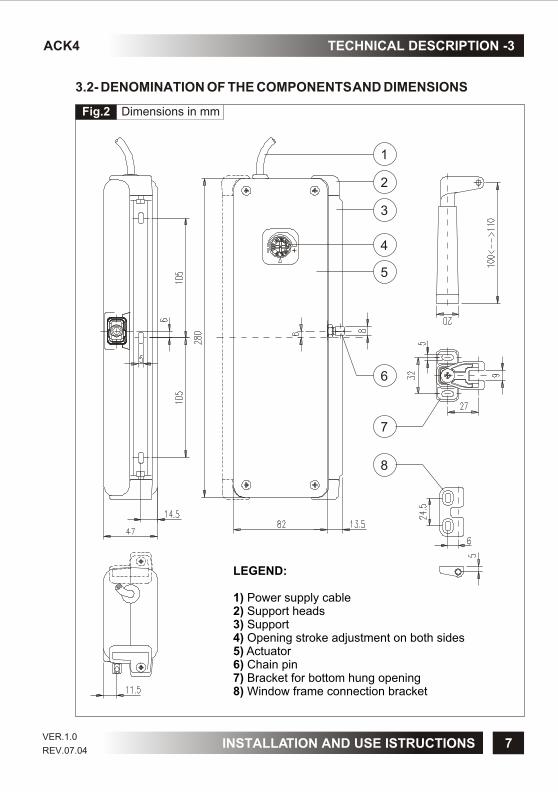
3.2- DENOMINATION OF THE COMPONENTS AND DIMENSIONS
TECHNICAL DESCRIPTION -3
LEGEND:
1) Power supply cable2) Support heads3) Support4) Opening stroke adjustment on both sides5) Actuator6) Chain pin7) Bracket for bottom hung opening8) Window frame connection bracket
1
4
5
3
2
6
8
7
Fig.2
INSTALLATION AND USE ISTRUCTIONS
Dimensions in mm
VER.1.0
REV.07.04
8
ACK43- TECHNICAL DESCRIPTION
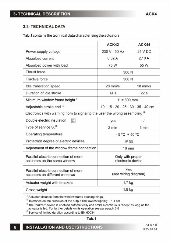
3.3- TECHNICAL DATA
Tab.1 contains the technical data characterising the actuators.
Tab.1
Power supply voltage
Absorbed current
Absorbed power with load
Thrust force
Tractive force
Idle translation speed
Duration of idle stroke
Minimum window frame height (1)
Adjustable stroke end (2)10 - 15 - 20 - 25 - 30 - 35 - 40 cm
Double electric insulation
Type of service (4) S2
230 V - 50 Hz
ACK42
0,32 A
75 W
300 N
300 N
28 mm/s
14 s
H = 800 mm
2 min
Operating temperature
Protection degree of electric devices
Adjustment of the window frame connection
Parallel electric connection of more actuators on the same window
Only with proper electronic device
Parallel electric connection of moreactuators on different windows
Actuator weight with brackets
Gross weight
(1)
(2)
(3)
(4)
Actuator distance from the window frame opening hinge
Tolerance on the precision of the output limit switch tripping: +/- 1 cm
The "buzzer" device is enabled automatically and emits a continuous "beep" as long as the actuator is fed. For further details on its operation see paragraph 5.6
Service of limited duration according to EN 60034
- 5 ºC + 50 ºC
IP 55
10 mm
Yes (see wiring diagram)
1,7 kg
1,9 kg
24 V DC
ACK44
2,10 A
55 W
18 mm/s
22 s
/
3 min
INSTALLATION AND USE ISTRUCTIONS
yes
(3)Electronics with warning horn to signal to the user the wrong assembling
VER.1.0
REV.07.04
9
ACK4 TECHNICAL DESCRIPTION -3
3.5- DESTINATION OF USE
THE ACTUATOR HAS BEEN DESIGNED AND MANUFACTURED TO PERFORM AUTOMATICALLY, BY MEANS OF A CONTROL DEVICE, THE OPENING AND CLOSING OF TOP HUNG WINDOWS, BOTTOM HUNG WINDOWS, PIVOT WINDOWS, AND SKYLIGHTS.
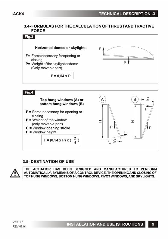
3.4- FORMULAS FOR THE CALCULATION OF THRUST AND TRACTIVE FORCE
Top hung windows (A) or bottom hung windows (B)
F = Force necessary for opening or closingP = Weight of the window (only movable part)C = Window opening strokeH = Window height
F = (0,54 x P) x ( )CH
P
F
H
CB
P
F
H
C
A
Fig.3
Fig.4
F
P
Horizontal domes or skylights
F= Force necessary for opening or closingP= Weight of the skylight or dome (Only movable part)
F = 0,54 x P
INSTALLATION AND USE ISTRUCTIONSVER.1.0
REV.07.04

3.6- USE LIMITS
The actuator has been designed and manufactured exclusively for the destination of
use given in par.3.5, therefore, any other type of use is strictly forbidden in order to
assure in any moment the safety of the installer and of the user, as well as the
efficiency of the actuator itself.
IT IS STRICTLY FORBIDDEN TO USE THE ACTUATOR FOR IMPROPER USES OTHER THAN THE ONE FORESEEN BY THE MANUFACTURER (SEE PAR.3.5).
IT IS STRICTLY FORBIDDEN TO INSTALL THE ACTUATOR ON THE EXTERNAL SIDE OF THE WINDOW FRAME SUBJECT TO ATMOSPHERIC AGENTS (RAIN, SNOW, ETC.).
THE USE OF THE ACTUATOR IN ENVIRONMENTS WITH POTENTIALLY EXPLOSIVE ATMOSPHERE IS STRICTLY FORBIDDEN.
IT IS COMPULSORY TO KEEP THE PACKAGE AND THE ACTUATOR OUT OF REACH OF CHILDREN.
3.7- PACKAGE
Each standard package of the product (cardboard box) contains (Fig.5):
• No. 1 Actuator equipped with power supply cable;
• No. 1 Support (Ref.A);
• No. 1 Bracket for hopper opening (Ref.B);
• No. 1 Small parts package (window connection bracket, nuts, pin and fastening
screws for aluminium window frames) (Ref.C);
• No. 1 Adhesive drilling template (Ref.D);
• No. 1 Installation and use instructions (Ref.E).
MAKE SURE THAT THE ABOVE DESCRIBED COMPONENTS ARE CONTAINED IN THE PACKAGE, AS WELL AS THAT THE ACTUATOR HAS NOT BEEN DAMAGED DURING TRANSPORT.
SHOULD ANY ANOMALY BE DETECTED, IT IS FORBIDDEN TO INSTALL THE ACTUATOR, AND IT IS COMPULSORY TO REQUIRE TECHNICAL ASSISTANCE FROM YOUR DEALER OR THE MANUFACTURER.
THE PACKAGING (PAPER, PLASTIC, ETC.) HAS TO BE DISPOSED ACCORDING TO THE LAWS IN FORCE.
10
3- TECHNICAL DESCRIPTION ACK4
INSTALLATION AND USE ISTRUCTIONS
EX
VER.1.0
REV.07.04

A
CB
ED
Fig.5
11
ACK4 TECHNICAL DESCRIPTION -3
INSTALLATION AND USE ISTRUCTIONSVER.1.0
REV.07.04
ISTRUZIONI PER L’INSTALLAZIONE E L'USO
ORIGINALI
BREVETTATO
PRIMA DI INSTALLARE E UTILIZZARE L’ATTUATORE È OBBLIGATORIO CHE
L’INSTALLATORE E L’UTILIZZATORE LEGGANO E COMPRENDANO
IN TUTTE LE SUE PARTI IL PRESENTE MANUALE.
IL PRESENTE MANUALE È PARTE INTEGRANTE DELL’ATTUATORE E DEVE
OBBLIGATORIAMENTE ESSERE CONSERVATO
PER FUTURI RIFERIMENTI FINO ALLA DEMOLIZIONE DELLO STESSO.
ATTUATORE A CATENA PER
AUTOMAZIONE FINESTRE ACK4
COD. 0P5000REV. 05/03
PATENTED
BEFORE INSTALLING AND USING THE ACTUATOR, IT IS
COMPULSORY FOR THE INSTALLER AND THE USER TO READ
AND UNDERSTAND THIS MANUAL IN ALL ITS PARTS.
THIS MANUAL IS INTEGRAL PART OF THE ACTUATOR
AND MUST BE PRESERVED FOR FUTURE REFERENCE
UNTIL DEMOLITION OF THE SAME.
ACK4
INSTALLATION AND USE INSTRUCTIONS CHAIN ACTUATOR FOR
WINDOW AUTOMATION
P/N 0P5101VER.1.0 REV.07.04

4.1- PROTECTION AGAINST ELECTRIC HAZARD
The actuator is protected against electric hazard due to direct and indirect contacts.
The protection measures against direct contacts aim at protecting people against
hazards due to contact with active parts, usually live parts; while the protection
measures against indirect contacts aim at protecting people against hazards due to
conducing part, which are usually insulated, but could become live in case of failure
(insulation failure).
The adopted protection measures are the following:
1) Insulation of live parts by means of a plastic material body;
2) Enclosure with suitable protection degree;
3) Only for mod. ACK42 equipped with double insulation: Protection of passive type
given by the use of components with double insulation, also called components of
class II or with equivalent insulation (
). 4.2- RESIDUAL RISKS
The actuator does not have residual risks. The installer and the user are herewith
informed that after the actuator has been installed on the window, the actuator drive can
accidentally generate the following residual risk:
Residual risk:
Hazard of squashing or dragging of body parts inserted between the movable and the
fix part of the window frame.
Exposure frequency:
Accidental and when the installer or the user decides to perform a wrong voluntary
action.
Severity of the damage:
Light lesions (usually reversible).
Adopted measures:
Before enabling the device, it is compulsory to verify that near the window there are not
persons, animals or things whose safety may be accidentally jeopardized. During
actuator operation, it is compulsory to be in a safe control position assuring visual
control on the window movement.
it is forbidden to perform the connection to the
earthing system of the actuators equipped with double insulation
12
4- SAFETY ACK4
INSTALLATION AND USE ISTRUCTIONSVER.1.0
REV.07.04
5.1- GENERAL INSTRUCTIONS
THE ACTUATOR INSTALLATION CAN BE PERFORMED EXCLUSIVELY BY COMPETENT AND QUALIFIED TECHNICAL PERSONNEL SATISFYING THE PROFESSIONAL AND TECHNICAL REQUIREMENTS FORESEEN BY THE LAWS IN FORCE IN THE COUNTRY OF INSTALLATION.
THE ACTUATOR PERFORMANCE MUST BE SUFFICIENT TO ASSURE THE CORRECT MOVEMENT OF THE WINDOW. IT IS COMPULSORY TO VERIFY THE THRUST OR TRACTIVE FORCE ACCORDING TO THE TYPE AND WEIGHT OF THE WINDOW (PAR. 3.4). IT IS FORBIDDEN TO EXCEED THE LIMITS GIVEN IN TAB.1 CONCERNING THE TECHNICAL DATA (PAR.3.3).
THE ACTUATOR INSTALLATION MUST BE PERFORMED EXCLUSIVELY WITH CLOSED WINDOW OR SKYLIGHT.
BEFORE PERFORMING THE INSTALLATION OF THE ACTUATOR ON HOPPER WINDOWS, VERIFY THAT ON BOTH SIDES OF THE WINDOW TWO COMPASS STROKE LIMIT DEVICES ARE INSTALLED IN ORDER TO AVOID THE ACCIDENTAL FALL OF THE WINDOW.
FOR CORRECT OPERATION OF THE ACTUATOR, THE WINDOW MUST HAVE A MINIMUM HEIGHT OF 800 mm (DISTANCE OF THE ACTUATOR FROM THE WINDOW OPENING HINGE). OTHERWISE, ASK YOUR DEALER OR THE MANUFACTURER FOR THE NECESSARY ACCESSORIES FOR A CORRECT INSTALLATION.
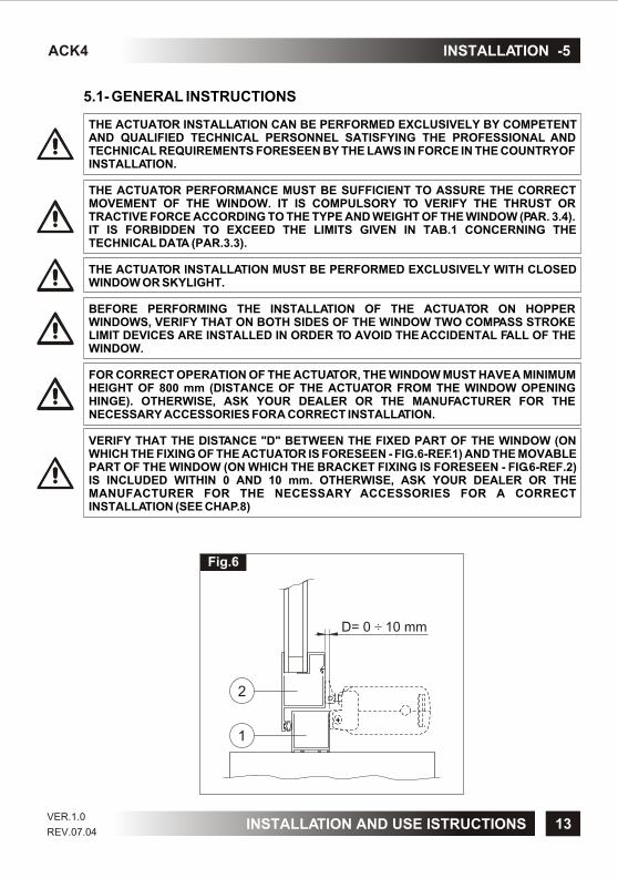
VERIFY THAT THE DISTANCE "D" BETWEEN THE FIXED PART OF THE WINDOW (ON WHICH THE FIXING OF THE ACTUATOR IS FORESEEN - FIG.6-REF.1) AND THE MOVABLE PART OF THE WINDOW (ON WHICH THE BRACKET FIXING IS FORESEEN - FIG.6-REF.2) IS INCLUDED WITHIN 0 AND 10 mm. OTHERWISE, ASK YOUR DEALER OR THE MANUFACTURER FOR THE NECESSARY ACCESSORIES FOR A CORRECT INSTALLATION (SEE CHAP.8)
13
ACK4 INSTALLATION -5
2
1
D= 0 10 mm÷
Fig.6
INSTALLATION AND USE ISTRUCTIONSVER.1.0
REV.07.04

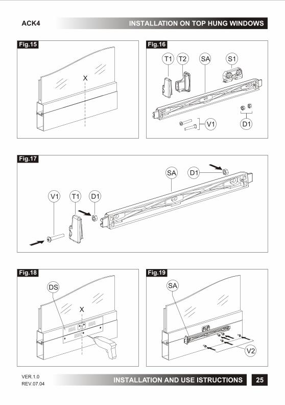
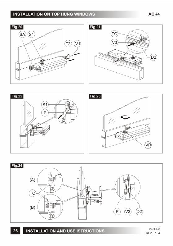
5.2- TOP HUNG WINDOWS (Fig. 7 and 15÷24)
1) Open the package (par.3.7) and extract the various components;
2) Fig.15- With a pencil draw the centre line "X" of the window frame;
3) Fig.16- Select the following components: bracket "S1", support "SA", two nuts "D1", two screws "V1", heads "T1" and “T2";
4) Fig.17- Insert the two nuts "D1" on the support "SA" and mount the head "T1" by fixing it using screw "V1";
5) Fig. 18- Cut out the adhesive template "DS" and apply it on the window frame centring it on the previously drawn centre line "X";
CAUTION: FOR NON-COPLANAR WINDOW FRAMES, IT IS NECESSARY TO CUT THE TEMPLATE CONCERNED PART AND TO APPLY IT ON THE WINDOW FRAME PAYING ATTENTION TO KEEP IT IN THE SAME REFERENCE POSITION.
6) With a suitable drill, create on the window frame holes having the related diameter, given on the adhesive template "DS";
7) Fig.19- Mount the support "SA" on the fix window frame with the screws "V2"; Check the perfect horizontal and vertical alignment with the window frame;
8) Fig.20- Mount the bracket "S1" on the movable window frame with the screws "V2";9) Mount the actuator on the support "SA", place the head "T2" and tighten the screw
"V1;
VERIFY THAT THE CHAIN END "TC" IS ON THE SAME AXIS OF THE BRACKET "S1". OTHERWISE, LOOSEN THE FIXING SCREWS AND POSITION IT CORRECTLY. WHEN THE DEVICES ARE NOT COAXIAL, THIS MAY DAMAGE THE ACTUATOR AND THE WINDOW FRAME (FIG. 8).
14
ACK45- IINSTALLATION
Fig.7
Fig.8
TC TCS1 S1
NO YES
INSTALLATION AND USE ISTRUCTIONSVER.1.0
REV.07.04
15
INSTALLATION -5ACK4
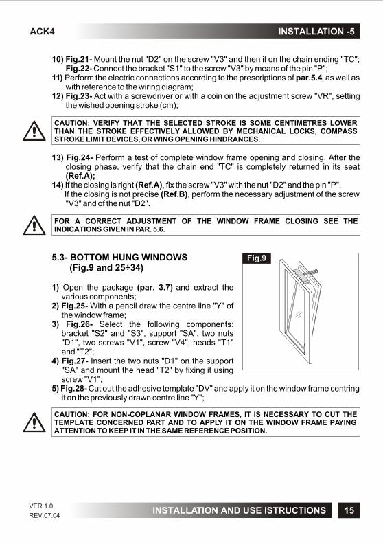
10) Fig.21- Mount the nut "D2" on the screw "V3" and then it on the chain ending "TC"; Fig.22- Connect the bracket "S1" to the screw "V3" by means of the pin "P";
11) Perform the electric connections according to the prescriptions of par.5.4, as well as with reference to the wiring diagram;
12) Fig.23- Act with a screwdriver or with a coin on the adjustment screw "VR", setting the wished opening stroke (cm);
CAUTION: VERIFY THAT THE SELECTED STROKE IS SOME CENTIMETRES LOWER THAN THE STROKE EFFECTIVELY ALLOWED BY MECHANICAL LOCKS, COMPASS STROKE LIMIT DEVICES, OR WING OPENING HINDRANCES.
13) Fig.24- Perform a test of complete window frame opening and closing. After the closing phase, verify that the chain end "TC" is completely returned in its seat (Ref.A);
14) If the closing is right (Ref.A), fix the screw "V3" with the nut "D2" and the pin "P". If the closing is not precise (Ref.B), perform the necessary adjustment of the screw
"V3" and of the nut "D2".
FOR A CORRECT ADJUSTMENT OF THE WINDOW FRAME CLOSING SEE THE INDICATIONS GIVEN IN PAR. 5.6.
5.3- BOTTOM HUNG WINDOWS (Fig.9 and 25÷34)
1) Open the package (par. 3.7) and extract the various components;
2) Fig.25- With a pencil draw the centre line "Y" of the window frame;
3) Fig.26- Select the following components: bracket "S2" and "S3", support "SA", two nuts "D1", two screws "V1", screw "V4", heads "T1" and "T2";
4) Fig.27- Insert the two nuts "D1" on the support "SA" and mount the head "T2" by fixing it using screw "V1";
5) Fig.28- Cut out the adhesive template "DV" and apply it on the window frame centring it on the previously drawn centre line "Y";
CAUTION: FOR NON-COPLANAR WINDOW FRAMES, IT IS NECESSARY TO CUT THE TEMPLATE CONCERNED PART AND TO APPLY IT ON THE WINDOW FRAME PAYING ATTENTION TO KEEP IT IN THE SAME REFERENCE POSITION.
Fig.9
INSTALLATION AND USE ISTRUCTIONSVER.1.0
REV.07.04

16
ACK45- INSTALLATION
6) With a suitable drill, create on the window frame holes having the related diameter,
given on the adhesive template "DV";
7) Fig.29- Mount the support "SA" on the fix window frame with the screws "V2"; check
the perfect horizontal and vertical alignment with the window frame;
8) Fig.30- Mount the bracket "S2" on the movable window frame with the screws "V2";
9) Mount the actuator on the support "SA", place the head "T1" and tighten the screw
"V1;
VERIFY THAT THE CHAIN END "TC" IS ON THE SAME AXIS OF THE BRACKET "S1". OTHERWISE, LOOSEN THE FIXING SCREWS AND POSITION IT CORRECTLY. WHEN THE DEVICES ARE NOT COAXIAL, THIS MAY DAMAGE THE ACTUATOR AND THE WINDOW FRAME (SEE Fig.8).
10) Fig.31- Mount the nut "D2" on the screw "V3" and then it on the chain end "TC";
Fig.32- Connect the bracket "S3" to bracket "S2" and fix it with the screw "V4".
Connect the bracket "S3" with the screw "V3" by means of the pin "P";
11) Perform the electric connections according to the prescriptions of par. 5.4, as well as
with reference to the wiring diagram;
12) Fig.33- Act with a screwdriver or with a coin on the adjustment screw "VR", setting
the wished opening stroke (cm);
CAUTION: VERIFY THAT THE SELECTED STROKE IS SOME CENTIMETRES LOWER THAN THE STROKE EFFECTIVELY ALLOWED BY MECHANICAL LOCKS, COMPASS STROKE LIMIT DEVICES, OR WING OPENING HINDRANCES.
13) Fig. 34- Perform a test of complete window frame opening and closing. After the
closing phase, verify that the chain end "TC" is completely returned in its seat
(Ref.A);
14) If the closing is right (Ref.A), fix the screw "V3" with the nut "D2" and the pin "P".
If the closing is not precise (Ref. B), perform the necessary adjustment of the screw
"V3" and of the nut "D2". If necessary, act also on the bracket "S3", unscrewing the
screw "V4" it is possible to unhook the two brackets modifying their coupling
position.
FOR A CORRECT ADJUSTMENT OF THE WINDOW FRAME CLOSING SEE THE INDICATIONS GIVEN IN PAR. 5.6.
INSTALLATION AND USE ISTRUCTIONSVER.1.0
REV.07.04

5.4- ELECTRIC CONNECTIONS (Wiring diagram)
W.
THE MAINS TO WHICH THE ACTUATOR IS CONNECTED MUST COMPLY WITH THE REQUIREMENTS OF THE LAWS IN FORCE IN THE COUNTRY OF INSTALLATION, AS WELL AS SATISFY THE TECHNICAL FEATURES GIVEN IN TAB.1 AND ON THE RATING PLATE AND THE "CE" MARKING (PAR.3.1), AS WELL AS BE EQUIPPED WITH A SUITABLE "EARTHING PLANT".
THE SECTION OF THE MAINS CABLES MUST BE PROPERLY SIZED ACCORDING TO THE ABSORBED ELECTRIC POWER (SEE RATING PLATE AND "CE" MARKING).
ANY TYPE OF ELECTRIC MATERIAL (PLUG, CABLE, TERMINALS, ETC.) USED FOR THE CONNECTION MUST BE SUITABLE FOR THE USE, WITH "CE" MARKING AND COMPLYING WITH THE REQUIREMENTS FORESEEN BY THE LAWS IN FORCE IN THE COUNTRY OF INSTALLATION.
IT IS COMPULSORY TO INSTALL UPSTREAM OF THE MAINS A SECTIONING DEVICE WITH A 30 mA DIFFERENTIAL PROTECTION, ASSOCIATED WITH THE EARTHING PLANT.
IT IS FORBIDDEN TO PERFORM THE CONNECTION TO THE EARTHING PLANT OF THE ACTUATORS EQUIPPED WITH DOUBLE INSULATION (MOD. ACK42).
5.5- CONTROL DEVICES
THE CONTROL DEVICES USED TO DRIVE THE ACTUATOR MUST ASSURE THE SAFETY CONDITIONS FORESEEN BY THE LAWS IN FORCE IN THE COUNTRY OF USE.
According to the different type of installations, the actuators can be driven by the
following control devices:
1) MANUAL PUSH-BUTTON:
Open/closed electric switch (I-0) controlling the single actuator or more than one
actuator simultaneously;
THE ELECTRIC CONNECTION OF THE ACTUATOR CAN BE PERFORMED ONLY BY COMPETENT AND QUALIFIED TECHNICAL PERSONNEL SATISFYING THE TECHNICAL AND PROFESSIONAL REQUIREMENTS FORESEEN BY THE LAW IN FORCE IN THE COUNTRY OF INSTALLATION ISSUING TO THE CUSTOMER A DECLARATION OF CONFORMITY FOR THE CONNECTION AND/OR THE PLANT PERFORMED.
BEFORE PERFORMING THE ELECTRIC CONNECTION OF THE ACTUATOR, VERIFY THE CORRECT INSTALLATION ON THE WINDO
17
ACK4 INSTALLATION -5
INSTALLATION AND USE ISTRUCTIONSVER.1.0
REV.07.04
2) CONTROL AND FEEDING UNIT:
Microprocessor control units (e.g.: Mod. TF, EVP, etc.) controlling the single actuator
or more than one actuator simultaneously by means of one or more manual push-
buttons, an infrared remote control or a 433 Mhz radio control.
To these control units, it is possible to connect the rain sensors (RPR - 12V), the wind
sensor (RW) and the brightness sensor (RL);
3) SYNCHRONIZATION UNIT:
Microprocessor control unit (e.g.: Mod. USA2) controlling by means of a manual
push-button the simultaneous operation of 2 or 3 actuators installed on a single
window assuring the regular opening and closing movement.
5.6- ADJUSTMENT OF THE WINDOW FRAME CLOSING (Fig.24-34)
THE CORRECT ADJUSTMENT OF THE WINDOW FRAME CLOSING ASSURES THE LIFE AND THE TIGHTNESS OF THE SEALS, AS WELL AS THE GOOD OPERATION OF THE ACTUATOR.
A good method to perform the adjustment is to let the chain go back without load into the
actuator and, then, to measure the position of the chain ending with reference to the
external casings.
Then, tighten the window frame fixing screw and let the chain go back.
The adjustment is right, when with closed window the chain ending has the same
position detected during the test without load.
As given in Fig.24-B (top hung windows) and in Fig.34-B (bottom hung windows),
although the window is closed, part of the chain ending or of the chain itself has not
come back completely into the actuator casings causing the failed tripping of the related
limit switch related to the chain re-entering. In this case, the actuator motor remains
under conditions of maximum stress, until the electronic protection trips and the
"BUZZER" is enabled.
This warning horn emits a continuous "beep" as long as the actuator is
connected to the power supply.
CONSIDERING THAT THIS ADDITIONAL SAFETY DEVICE HAS BEEN DEVELOPED IN ORDER TO OFFER A RAPID SYSTEM TO DETECT ANY EVENTUAL ANOMALY IN THE ASSEMBLY OF THE DEVICE, FOR A CORRECT INSTALLATION OF THE PRODUCT IT IS COMPULSORY TO FOLLOW ALL THE ASSEMBLING PROCEDURES DESCRIBED IN THIS MANUAL.
18
ACK45- INSTALLATION
INSTALLATION AND USE ISTRUCTIONSVER.1.0
REV.07.04

5.7- EMERGENCY PROCEDURES
Should it be necessary to open the window manually due to power supply failure or
mechanism block, follow these instructions:
BEFORE PERFORMING ANY TYPE OF INTERVENTION ON THE ACTUATOR AND ON THE WINDOW, IT IS COMPULSORY TO DISCONNECT THE POWER SUPPLY OF THE ACTUATOR AND TO PUT ON "0" THE EVENTUAL SWITCHES OF THE CONTROL DEVICES.
IT IS COMPULSORY TO PADLOCK THE MAIN SWITCH OF THE DISCONNECTION DEVICE INSTALLED ON THE MAINS IN ORDER TO AVOID ANY UNEXPECTED START. IF THE MAIN SWITCH CANNOT BE PADLOCKED, IT IS COMPULSORY TO PLACE A SIGN FORBIDDING THE ENABLING.
1) Act on the pin "P" until it is completely extracted from the bracket "S1" (top hung
windows - Fig.10). Act on the pin "P" until it is completely extracted from the bracket
"S3" (bottom hung windows - Fig.11);
2) Open the window manually.
19
INSTALLATION -5ACK4
S1
P
Fig.10
P
S3
Fig.11
INSTALLATION AND USE ISTRUCTIONSVER.1.0
REV.07.04

6.1- USE OF THE ACTUATOR
THE ACTUATOR CAN BE USED ONLY BY A USER ACTING IN COMPLIANCE WITH THE INSTRUCTIONS GIVEN IN THIS MANUAL AND/OR IN THE MANUAL OF THE ACTUATOR COMMAND DEVICE (e.g.: WIND AND RAIN CONTROL UNIT).
BEFORE USING THE ACTUATOR, IT IS COMPULSORY FOR THE USER TO READ AND UNDERSTAND IN ALL ITS PARTS THIS MANUAL, AS WELL AS THE EVENTUAL MANUAL OF THE INSTALLED CONTROL DEVICE TYPE.
BEFORE OPERATING THE ACTUATOR, THE USER MUST COMPULSORILY VERIFY THAT NEAR AND/OR UNDER THE WINDOW THERE ARE NOT ANY PERSON, ANIMAL AND THING WHOSE SAFETY MAY BE ACCIDENTALLY JEOPARDISED (SEE PAR. 4.2).
DURING THE OPERATION OF THE ACTUATOR CONTROL DEVICE, THE USER HAS TO COMPULSORILY OCCUPY A CONTROL POSITION ASSURING VISUAL CONTROL ON THE WINDOW MOVEMENT.
THE FUNCTION EFFICIENCY AND THE RATED PERFORMANCE OF THE ACTUATOR, OF THE WINDOW FRAME ON WHICH IT IS INSTALLED AND OF THE ELECTRIC EQUIPMENT MUST BE VERIFIED STEADILY IN TIME BY PERFORMING, WHEN NECESSARY, INTERVENTIONS OF ROUTINE AND SUPPLEMENTARY MAINTENANCE ASSURING THE OPERATION CONDITIONS IN COMPLIANCE WITH THE SAFETY REGULATIONS.
ALL ABOVE MENTIONED MAINTENANCE INTERVENTIONS MAY BE PERFORMED EXCLUSIVELY BY TECHNICAL COMPETENT AND QUALIFIED TECHNICAL PERSONNEL SATISFYING THE TECHNICAL AND PROFESSIONAL REQUIREMENTS FORESEEN BY THE LAW IN FORCE IN THE COUNTRY OF INSTALLATION.
The use of the actuator allows to control automatically the opening and closing of the
window according to the type of control device installed (see par. 5.5).
ACK46- USE AND OPERATION
20 INSTALLATION AND USE ISTRUCTIONSVER.1.0
REV.07.04
8.1- GENERAL INSTRUCTIONS
THE USE OF "NON-ORIGINAL" SPARE PARTS AND ACCESSORIES WHICH MAY ENDANGER THE SAFETY AND THE EFFICIENCY OF THE ACTUATOR IS FORBIDDEN. THIS ACTION SHALL INVOLVE THE WARRANTY EXPIRATION.
ORIGINAL SPARE PARTS AND ACCESSORIES HAVE TO BE REQUESTED EXCLUSIVELY TO YOUR DEALER OR TO THE MANUFACTURER STATING TYPE, MODEL, SERIAL NUMBER, AND YEAR OF CONSTRUCTION OF THE ACTUATOR.
21
DEMOLITION -7
SPARE PARTS AND ACCESSORIES UPON REQUEST -8
ACK4
ACK4
7.1- GENERAL INSTRUCTIONS
THE DEMOLITION OF THE ACTUATOR MUST OCCUR IN COMPLIANCE WITH THE LAWS IN FORCE ON ENVIRONMENT PROTECTION.
DIFFERENTIATE THE PARTS MAKING UP THE ACTUATOR ACCORDING TO THEIR DIFFERENT MATERIAL TYPE (PLASTIC, ALUMINIUM, ETC.).
INSTALLATION AND USE ISTRUCTIONSVER.1.0
REV.07.04

ACK4
22
COD. 0B0006
D=
20
3
0÷
D=
0
0÷ 1
D=
30
4
0÷
D=
10
2
0÷
COD. 0B0007
COD. 0B0005COD. 0B0008
(Standard)
Fig.12
FRAME ADJUSTMENT PINS
8- SPARE PARTS AND ACCESSORIES UPON REQUEST
VER.1.0
REV.07.04INSTALLATION AND USE ISTRUCTIONS

ACK4
23
FRAME
WING
106.5±4
2
85
27
50
21
.5
1.7
11
.81
5.2
35
22.3
50 58.5
54.4
45.5
47
.8
23
.5
2.8
(A)
(D)
Fig.13
SINGLE SWIVEL BRACKET (COD. 1A1665-66-67)
VERTICAL MOUNTING BRACKET (COD. 3A1380-81-82)
FRAME
WING
(A)
(D)
FOR A CORRECT OPERATION, THE WINDOW MUST HAVE A MIN. HEIGHT OF 800 mm (ACTUATOR DISTANCE FROM THE WINDOW FRAME OPENING HINGE).
SPARE PARTS AND ACCESSORIES UPON REQUEST -8
INSTALLATION AND USE ISTRUCTIONS
Window frameadjustmentpin code
0B0008(Standard)
0B0005
0B0007
0B0006
Overlapped part(D)
0 ÷ 10 mm
10 ÷ 20 mm
20 ÷ 30 mm
30 ÷ 40 mm
THE FIXING POSITION (A) HAS TO BE VERIFIED AND EVALUATED ACCORDING TO THE PROFILE/WIDTH OF THE WING/FRAME AND OF THE WINDOW LIGHT. THE ACTUATOR WITH SWIVEL BRACKET CAN BE SUBJECT TO A MAX. THRUST FORCE NOT EXCEEDING 250N. FOR A CORRECT OPERATION, THE WINDOW MUST HAVE A MIN. HEIGHT OF 400 mm (ACTUATOR DISTANCE FROM THE WINDOW FRAME OPENING HINGE).
VER.1.0
REV.07.04

24
ACK4
THE FIXING POSITION (A) HAS TO BE VERIFIED AND EVALUATED ACCORDING TO THE PROFILE/WIDTH OF THE WING/FRAME AND OF THE WINDOW LIGHT. THE ACTUATOR WITH SWIVEL BRACKET CAN BE SUBJECT TO A MAX. THRUST FORCE NOT EXCEEDING 250N. FOR A CORRECT OPERATION, THE WINDOW MUST HAVE A MIN. HEIGHT OF 400 mm (ACTUATOR DISTANCE FROM THE WINDOW FRAME OPENING HINGE).
Fig.14SMALL SWIVEL BRACKET (COD. 3A1396-97-98-99)
FRAME
WING
(A)
(D)
FRAME
WING
(D)
BIG SWIVEL BRACKET (COD.3A1391-92-93-94)
INSTALLATION AND USE ISTRUCTIONS
Window frameadjustmentpin code
0B0008(Standard)
0B0005
0B0007
0B0006
Overlapped part(D)
0 ÷ 10 mm
10 ÷ 20 mm
20 ÷ 30 mm
30 ÷ 40 mm
8- SPARE PARTS AND ACCESSORIES UPON REQUEST
VER.1.0
REV.07.04
ACK4
DS
X
V2
SA
T1V1 D1
D1SA
X
V1 D1
T1 T2 S1SA
Fig.15
Fig.17
Fig.18 Fig.19
Fig.16
INSTALLATION ON TOP HUNG WINDOWS
25INSTALLATION AND USE ISTRUCTIONSVER.1.0
REV.07.04
ACK4
(A)
(B)
TC
P D2V3
T2 V1
S1SA
V3
TC
D2
S1
P
VR
Fig.20
Fig.22
Fig.24
Fig.21
Fig.23
26
INSTALLATION ON TOP HUNG WINDOWS
VER.1.0
REV.07.04INSTALLATION AND USE ISTRUCTIONS

ACK4
V1
D1
T2
T1
V2
Y
Y
DV
SA
V4 S3S2
T2V1 D1
D1SA
SA
Fig.25
Fig.28
Fig.27
Fig.26
Fig.29
INSTALLATION ON BOTTOM HUNG WINDOWS
27INSTALLATION AND USE ISTRUCTIONSVER.1.0
REV.07.04

ACK4
(A)
(B)
V1
T1
TC
SA S2
P
D2 V3
TC
D2
V3
S2 S3 V4
P
V3
VR
Fig.30
Fig.32
Fig.34
Fig.31
Fig.33
28 INSTALLATION AND USE ISTRUCTIONS
INSTALLATION ON BOTTOM HUNG WINDOWS
VER.1.0
REV.07.04

IT I
S F
OR
BID
DE
N T
O P
ER
FO
RM
TH
E C
ON
NE
CT
ION
TO
TH
E
EA
RT
HIN
G S
YS
TE
M O
F T
HE
AC
TU
AT
OR
S E
QU
IPP
ED
WIT
H
DO
UB
LE
INS
UL
AT
ION
(MO
D. A
CK
42
).
DRAWINGS FOR INSTALLATIONACK4
CL
OS
ES
BL
UE
(BL
AC
K)
BR
OW
N(R
ED
)
24
V
OP
EN
S
AC
K4
4A
CK
44
CL
OS
ES
BL
UE
(BL
AC
K)
BR
OW
N(R
ED
)
24
V OP
EN
S
AC
K4
4
CL
OS
ES
BL
AC
K
23
0V
~5
0H
z
N L
OP
EN
S
AC
K4
2A
CK
42
BR
OW
N
CL
OS
ES
BL
AC
K
GR
EY
(LIG
HT
BL
UE
)
GR
EY
(LIG
HT
BL
UE
)
23
0V
~5
0H
z
N L
OP
EN
S
AC
K4
2
BR
OW
N
23
0 V
24
V
IT IS
CO
MP
UL
SO
RY
TO
IN
STA
LL
UP
ST
RE
AM
OF
TH
E M
AIN
S A
S
EC
TIO
NIN
G
DE
VIC
E
WIT
H
30
m
A
DIF
FE
RE
NT
IAL
PR
OT
EC
TIO
N, A
SS
OC
IAT
ED
TO
TH
E E
AR
TH
ING
SY
ST
EM
.
Wiring diagram
29INSTALLATION AND USE ISTRUCTIONSVER.1.0
REV.07.04
30
ACK4REMARKS
INSTALLATION AND USE ISTRUCTIONSVER.1.0
REV.07.04

31INSTALLATION AND USE ISTRUCTIONS
CERTIFICATE OF GUARANTEEACK4
MODELTECHNICAL REPORT
SERIAL No.
CUSTOMER
ADDRESS
RETAILER’S NAME (STAMP AND SIGNATURE)
The warranty for the products, and their single parts, defective for poor materials or manufacturing defects is extended for a period of 24 months from the date of dispatch by the manufacturer.The manufacturer provides that the products are reliable, which means that he undertakes to repair or replace free of charge any of the parts proved to be defective in materials or manufacturing during the warranty period, in the shortest possible time. The purchaser shall not expect any refund for any damage due to improper installation or any other expenses. Such warranty will not however apply to any particularly fragile parts, or to parts exposed to natural wear as well as to corrosive operations and to current overloads (even if only temporary), etc. The manufacturer shall not be considered liable against any damages due to improper installation, manoeuvring or insertion, as well as to excessive solicitations or misuse.The manufacturer shall not be liable if the product has been modified, dismantled, if the label is missing or if it shows clear signs of collision or other. Repairs under guarantee are considered "ex manufacturer's factory", which means that all the arising transport expenses (in- and outward) are always to the purchaser charge. For any inspections by a skilled staff, cost of labour shall be to the manufacturer charge. Displacement costs (in- and outward journey), journey hours, board and lodging must, on the other hand, be refunded from the purchaser. Such warranty has validity only if the present form, being part of the instructions manual, is duly filled in and the damage cause is clearly described in the assistance report.
The products must be installed and used in compliance with the technical features and the instructions given by TOPP, as well as according to the safety regulations and the standards that rule the installation and employment of the electrical devices in the country where the products are installed and used. For such reason, the purchaser expressly relieves TOPP from any responsibility arising from improper use, from the inobservance of the safety regulations, of the technical specifications as well as of the operating instructions.
VER.1.0
REV.07.04

TOPP SPAVia Galvani, 59 - 36066 Sandrigo (VI) - Italia
Tel. +39 0444 656700 - Fax +39 0444 656701 [email protected] - www.topp.it