Embed Size (px)
DESCRIPTION
Installation and Testing Results of Long Island Transmission Level HTS Cable
Citation preview

1692 IEEE TRANSACTIONS ON APPLIED SUPERCONDUCTIVITY, VOL. 19, NO. 3, JUNE 2009
Installation and Testing Results of Long IslandTransmission Level HTS Cable
James F. Maguire, Frank Schmidt, Shawn Bratt, Tom E. Welsh, and Jie Yuan
Abstract—The first long length, transmission level voltage, colddielectric, high temperature superconductor power cable has beensuccessfully installed in the Long Island Power Authority (LIPA)grid. The cable is capable of carrying 574 MVA at a voltage of 138KV. Three 600 m long phase conductors were manufactured andshipped to the LIPA site. The installation process included pullingthree cables through three separate 600 m long undergroundconduits and assembly of three terminations at each end. Theproject has been funded by the US Department of Energy and isled by American Superconductor. The project team is comprisedof Nexans, Air Liquide and LIPA. This paper describes the cablesystem, installation process and an overview of various testingresults before and after installation. In addition, details of aninitial successful cool-down process are presented. It also includesthe performance results in grid operation.
Index Terms—Superconducting cable, superconducting trans-mission, transmission level HTS cable.
I. INTRODUCTION
H IGH-CAPACITY, underground HTS power cable haslong been considered an enabling technology for power
transmission. Power cables using HTS wires have been devel-oped to increase the power capacity in utility power networkswhile maintaining a relatively small footprint. Over the pastdecade, several HTS cable designs have been developed anddemonstrated [1]–[4]. All HTS cables have a much higherpower density than copper-based cables at the similar voltagelevels. Moreover, because they are actively cooled and ther-mally independent of the surrounding environment, they can fitto much more compact installations than conventional coppercables, without concern for spacing or special backfill materialsto assure dissipation of heat. This advantage reduces environ-mental impacts and enables the installation of compact cablesystems with three to five times more capacity than conven-tional circuits at the same or lower voltage. In addition, HTScables exhibit much lower resistive losses than conventionalcopper or aluminum conductors.
Manuscript received August 25, 2008. First published June 23, 2009; currentversion published July 15, 2009. This work was supported in part by the USDepartment of Energy Grant DE-FC36_03GO13032.
J. F. Maguire and J. Yuan are with American Superconductor Corporation,Devens, MA 01434 USA (e-mail: [email protected]; [email protected]).
F. Schmidt is with Nexans Deutschland Industries GmbH & Co. KG, Han-nover, Germany (e-mail: [email protected]).
S. Bratt is with Air Liquide Division Techniques Avancees, Sassenage, France(e-mail: [email protected]).
T. E. Welsh, is with Long Island Power Authority, Hicksville, NY 11801 USA(e-mail: [email protected]).
Color versions of one or more of the figures in this paper are available onlineat http://ieeexplore.ieee.org.
Digital Object Identifier 10.1109/TASC.2009.2018221
The project has been funded by the US Department of En-ergy. The project goal is to design, develop and demonstrate thefirst long length, transmission level voltage, cold dielectric, hightemperature superconductor power cable in a real power grid.The cable is designed for permanent installation in the LongIsland Power Authority (LIPA) grid and is able to carry 574MVA at a voltage of 138 kV. This paper reports the status of theproject. An overview of the cable design, refrigeration system,site design and installation process will be provided. Test resultsbefore and after cable installation will be discussed. In addition,the paper will present the cable performance data in grid oper-ation since it was successfully connected to the LIPA grid onApril 22, 2008.
II. PROJECT DESCRIPTION
The project is a Superconductivity Partnership Initiative(SPI) between the United States Department of Energy (DOE)and industry to develop a long length transmission voltage hightemperature superconductor power cable. American Super-conductor Corporation is the prime contractor as well as themanufacturer of the high temperature superconducting wires.Nexans is providing the development and manufacturing of thecable, terminations and cryostat as well as site and installationsupport, and Air Liquide is providing the cryogenic refriger-ation expertise, equipment, installation as well as operationsmonitoring and support. The host utility, LIPA, has provided thesite, civil work, controls and protection, transmission planningand the operation of the HTS cable. The cable system has beenmanufactured, installed and successfully connected to the LIPAgrid on April 22, 2008
III. CABLE SYSTEM SPECIFICATIONS
The cable system was designed to meet the following speci-fications:
As illustrated in Fig. 1, three HTS cables have been installedin the LIPA grid starting at the Holbrook Substation and headingnorth for a distance of 600 meters where a new switching sta-tion was installed. This new station houses the cryogenic refrig-erator, the HTS cable terminations, liquid nitrogen storage andthe necessary equipment for operation and control of the cablesystem. Figs. 2 and 3 show the north end and the south end ofcable system with three terminations, respectively. The power
1051-8223/$25.00 © 2009 IEEE
Authorized licensed use limited to: UNIVERSIDADE DE SAO PAULO. Downloaded on March 19,2010 at 12:13:14 EDT from IEEE Xplore. Restrictions apply.

MAGUIRE et al.: INSTALLATION AND TESTING RESULTS OF LONG ISLAND TRANSMISSION LEVEL HTS CABLE 1693
Fig. 1. Cable route starting from outside Holbrook substation and headingnorth along existing ROW.
Fig. 2. North end of the cable system with three terminations.
Fig. 3. South end of the cable system (grounding station).
to be transmitted by the new HTS cable system is taken from anexisting 138 KV overhead circuit which will remain available inparallel as a backup. Fig. 4 shows the one line electrical diagramof the system.
Fig. 4. One Line electrical diagram of installation.
Fig. 5. Structure of superconducting cable phase.
IV. CABLE AND TERMINATION DESIGN
A. General Description
The cable used in the LIPA project is a cold dielectric de-sign. The cable system contains three individual HTS cables andsix terminations. The cable configuration consists of a copperformer, two HTS conductor layers, an insulation layer, an HTSscreen layer, a copper screen stabilizer and a cryogenic enve-lope. Fig. 5 shows a schematic of cable cross section. Duringthe normal operation, the cable core is maintained at operatingtemperature by circulating sub-cooled liquid nitrogen.
Each cable phase is linked to an outdoor termination at bothends located in the substation areas that connects the cable tothe LIPA grid. The terminations provide both a connection tothe cable and interface to the cable cooling system.
In order to enable the appropriate opposite current flow in thesuperconducting shield layers the screens of the individual cablephases are connected at both cable ends. This is done througha cryogenic jumper cable located and connected at the cableterminations. A termination sketch can be seen in Fig. 6.
B. Cable Operating Parameters
The selection of the cable operating parameters was driven bycoolant properties, Ic characteristics of the wire, the cable corecharacteristics and the fault conditions of the installation site[5]. The selection process took several iterations due to couplingof various parameters. Since nitrogen is used as the coolant,
Authorized licensed use limited to: UNIVERSIDADE DE SAO PAULO. Downloaded on March 19,2010 at 12:13:14 EDT from IEEE Xplore. Restrictions apply.

1694 IEEE TRANSACTIONS ON APPLIED SUPERCONDUCTIVITY, VOL. 19, NO. 3, JUNE 2009
Fig. 6. Superconducting cable termination.
TABLE IDESIGN AND ACTUAL SYSTEM PARAMETERS
the minimum operating temperature of approximately 65 K isselected, which is close to the solidification point. From thispoint on, the maximum operating temperature, the maximumoperating pressure and the diameter of the cable cryostat aredetermined. The criterion used in this project is that no bubblesare allowed to form at any point during a fault. As a result ofthis condition, the inlet operating pressure of 14.5 barg, LN2flow rate of 0.375 kg/s, the inner cryostat diameter of 83 mmand maximum operating temperature of 72 K are selected. Theaverage cryostat losses of 1.3 W/m/Phase and a total pressuredrop over the entire cable of 2 Bar were expected including theappropriate design margin Table I illustrates the final systemdesign parameters compared with the actual values achieved innormal operation.
C. Cable Qualification
To fully qualify the cabling process and for type testing, aprototype 30 meter cable and two full scale terminations werefabricated and tested by Nexans. The test setup is illustrated inFig. 7. Sub-cooled LN2 was used as coolant during entire test.Table II shows the test results.
D. HTS-Wire
The generation 1 BSCCO 2223 superconducting wires usedas current carrying elements are available in different qualitieswith regard to
• Critical current (Ic)• Mechanical stress tolerance• Hermeticity against .The cable design for this project is based on the use of
hermetic wires with a critical current of 135 A per wire at a
Fig. 7. Test setup of 30 m prototype cable.
TABLE IITESTING RESULTS ON 30 METER PROTOTYPE CABLE
at 77 K, in normal operation the cable operating temperature is 73 K andthe corresponding Ic is 4,880 amps.
width of 4.3 mm for the conductor layers and 105 amps forthe shield layer. The HTS wire Ic directly impacts the cableconductor design, the tolerance against mechanical stress isan important aspect that determines cable manufacturing andhandling requirements.
Based on experience with superconducting BSCCO-wires,hermeticity against is identified as an absolute requirementto prevent ballooning of HTS-wires during any thermal cyclesthe cable may see [6].
The LIPA cable required the production and supply of ap-proximately 155,000 meters of superconducting wire plus sev-eral kilometers of additional wire for qualification of the man-ufacturing processes for the cable. The wire was produced byAmerican Superconductor in 2005 and shipped to the Nexansfactory in Halden Norway for production of the cable.
E. Cable Fabrication
The cable manufacturing for this project was done by Nexansin Halden, Norway in 2006 on existing machines used for con-ventional cable manufacturing. The cable core was manufac-tured and shipped to Hannover, Germany for integration withthe cryostat which was manufactured there.
F. Cryostat Fabrication
The cryostat was manufactured directly over the cable core ina continuous fashion once the core arrived from Norway. Firstthe inner corrugated stainless tube was welded and corrugated.Upon completion of the corrugation, a leak test was performedto ensure that there were no issues with the materials or weldingafter corrugation. Then the thermal insulation system was in-stalled, again in a continuous fashion as shown in Fig. 8. Once
Authorized licensed use limited to: UNIVERSIDADE DE SAO PAULO. Downloaded on March 19,2010 at 12:13:14 EDT from IEEE Xplore. Restrictions apply.

MAGUIRE et al.: INSTALLATION AND TESTING RESULTS OF LONG ISLAND TRANSMISSION LEVEL HTS CABLE 1695
Fig. 8. Insulation system of cryostat being installed.
the insulation was installed the outer corrugated tube was in-stalled and another leak test was performed. The final step wasthe evacuation of the vacuum space and the activation of the get-ters which are used to ensure a long vacuum lifetime.
Once properly evacuated the cable, which was already on anappropriate shipping drum was packaged and shipped to the siteon Long Island.
V. REFRIGERATION SYSTEM COMMISSIONING
The refrigeration system used in DOE/LIPA project is basedon the existing refrigeration system designed for DOE/Edisonproject. The refrigeration system is based on turbo-Braytoncycle. Since two cable systems have different specifications,modifications were needed to make the existing refrigerationsystem work for the present project. The first one was thetotal cooling capacity, which was boosted from 4.3 kW to5.6 kW. The second area was the pressurized system usedfor relief or compensation of LN2 volume change during afault event. A cool-down skid has also been implemented tocontrol the cable and termination cool-down process to matchthe cooling rate specified by Nexans. All of the componentsfor the refrigeration system have been fabricated and shippedto the site in New York where they have been installed. Thecryogenic refrigeration system was successfully commissionedin September 2007. The system performance of the cryogenicrefrigerator has reached or exceeded the required specificationsas shown in Table I.
After commissioning, the cryogenic system was tested exten-sively prior to final cable cool-down. The tests include switchingbetween main refrigerator and back-up refrigerator, load varia-tion tests and refrigeration alarm system.
Fig. 9 shows a typical nominal operation of the cryogenicsystem without cable energized. After the system commissioningin September of 2007, refrigeration system has been continu-ously operating until the cable was ready to be cooled down.
VI. SITE
The site was completed in early 2007 and ready when thecable and terminations arrived. The cable phases were shippedseparately and pulled into the already installed conduit directly
Fig. 9. Refrigeration system performance without cable energized.
Fig. 10. Installation of first phase conductor.
Fig. 11. Installation of the terminations.
from the shipping spools. Once the phase conductor was in-stalled in the conduit the termination connections were made.In order to ensure the proper environment a temporary shelterwith environmental controls was installed over each end of thecable and termination while the interconnections were being as-sembled. Figs. 10 and 11 show the pulling operation as well asone of the final steps of the termination assembly.
VII. COOLDOWN OF CABLE SYSTEM
The cooldown process of cables and terminations was carriedout in a well controlled manner based on the temperature gra-dients at various locations specified by Nexans. A three-phase
Authorized licensed use limited to: UNIVERSIDADE DE SAO PAULO. Downloaded on March 19,2010 at 12:13:14 EDT from IEEE Xplore. Restrictions apply.
1696 IEEE TRANSACTIONS ON APPLIED SUPERCONDUCTIVITY, VOL. 19, NO. 3, JUNE 2009
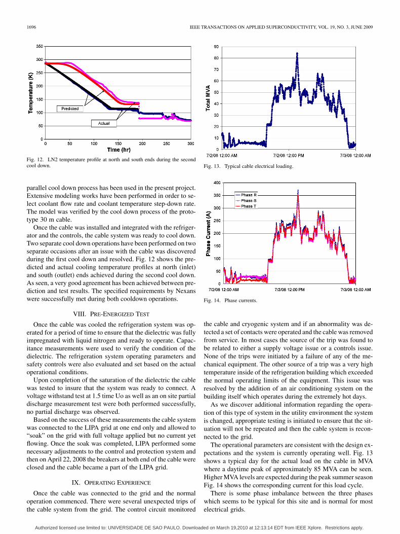
Fig. 12. LN2 temperature profile at north and south ends during the secondcool down.
parallel cool down process has been used in the present project.Extensive modeling works have been performed in order to se-lect coolant flow rate and coolant temperature step-down rate.The model was verified by the cool down process of the proto-type 30 m cable.
Once the cable was installed and integrated with the refriger-ator and the controls, the cable system was ready to cool down.Two separate cool down operations have been performed on twoseparate occasions after an issue with the cable was discoveredduring the first cool down and resolved. Fig. 12 shows the pre-dicted and actual cooling temperature profiles at north (inlet)and south (outlet) ends achieved during the second cool down.As seen, a very good agreement has been achieved between pre-diction and test results. The specified requirements by Nexanswere successfully met during both cooldown operations.
VIII. PRE-ENERGIZED TEST
Once the cable was cooled the refrigeration system was op-erated for a period of time to ensure that the dielectric was fullyimpregnated with liquid nitrogen and ready to operate. Capac-itance measurements were used to verify the condition of thedielectric. The refrigeration system operating parameters andsafety controls were also evaluated and set based on the actualoperational conditions.
Upon completion of the saturation of the dielectric the cablewas tested to insure that the system was ready to connect. Avoltage withstand test at 1.5 time Uo as well as an on site partialdischarge measurement test were both performed successfully,no partial discharge was observed.
Based on the success of these measurements the cable systemwas connected to the LIPA grid at one end only and allowed to“soak” on the grid with full voltage applied but no current yetflowing. Once the soak was completed, LIPA performed somenecessary adjustments to the control and protection system andthen on April 22, 2008 the breakers at both end of the cable wereclosed and the cable became a part of the LIPA grid.
IX. OPERATING EXPERIENCE
Once the cable was connected to the grid and the normaloperation commenced. There were several unexpected trips ofthe cable system from the grid. The control circuit monitored
Fig. 13. Typical cable electrical loading.
Fig. 14. Phase currents.
the cable and cryogenic system and if an abnormality was de-tected a set of contacts were operated and the cable was removedfrom service. In most cases the source of the trip was found tobe related to either a supply voltage issue or a controls issue.None of the trips were initiated by a failure of any of the me-chanical equipment. The other source of a trip was a very hightemperature inside of the refrigeration building which exceededthe normal operating limits of the equipment. This issue wasresolved by the addition of an air conditioning system on thebuilding itself which operates during the extremely hot days.
As we discover additional information regarding the opera-tion of this type of system in the utility environment the systemis changed, appropriate testing is initiated to ensure that the sit-uation will not be repeated and then the cable system is recon-nected to the grid.
The operational parameters are consistent with the design ex-pectations and the system is currently operating well. Fig. 13shows a typical day for the actual load on the cable in MVAwhere a daytime peak of approximately 85 MVA can be seen.Higher MVA levels are expected during the peak summer seasonFig. 14 shows the corresponding current for this load cycle.
There is some phase imbalance between the three phaseswhich seems to be typical for this site and is normal for mostelectrical grids.
Authorized licensed use limited to: UNIVERSIDADE DE SAO PAULO. Downloaded on March 19,2010 at 12:13:14 EDT from IEEE Xplore. Restrictions apply.

MAGUIRE et al.: INSTALLATION AND TESTING RESULTS OF LONG ISLAND TRANSMISSION LEVEL HTS CABLE 1697
Fig. 15. Cryogenic system supply and return temperatures.
The cryogenic system is also operating well and very consis-tent with the system design. Fig. 15 shows the supply and returntemperatures for the refrigerator for the same day of operation.
It can be seen in Fig. 15 that there is indeed a temperaturechange during the day. This appears to be a result of the higheroperating ambient temperature and the solar loading on the ter-minations, and not a result of the increased current on the cable.It should be noted that there is a time delay of several hours dueto the system size and velocity of the liquid nitrogen. This datawas taken on a summer day when the temperature change wasapproximately 25 degrees F between nighttime and daytime andthe solar loading was high.
X. FUTURE WORKS
In 2007 a program to address the outstanding issues for inte-grating HTS cables into the utility grid was awarded to the currentproject team. This project will address the following issues:
• Field Joint• Field Reparable Cryostat• Modular High Efficiency Refrigeration System• Thermal Contraction Control within the Cable
In addition the new cable system is being developed to includethe ability to limit fault currents. Although this cable is not longenough to provide meaningful limitation of the fault currentexperienced at this location, the development, fabrication andqualification of this feature is included and will be tested anddemonstrated in a laboratory environment for use at transmis-sion voltages.
XI. CONCLUSION
A 138 kV, 3 phase transmission cable system has been suc-cessfully fabricated and integrated into the grid on Long IslandNY. It is the first demonstration of an HTS cable at transmissionvoltage on the grid. It has being designed to operate reliably andto withstand fault currents up to 51,000 amps RMS. The cablewill be operated for a least a full year until the LIPA 2 project isready to integrate into the site.
ACKNOWLEDGMENT
The authors thank the readiness review team for their tech-nical input and guidance.
REFERENCES
[1] S. Mukoyama et al., “Manufacturing and installation of the world’slongest HTS cable in the super-ACE project,” IEEE Trans. Applied Su-perconductivity, vol. 15, no. 2, June 2005.
[2] Y. Xin et al., “Introduction to China’s first live grid installed HTSpower cable system,” IEEE Trans. Applied Superconductivity, vol. 15,no. 2, June 2005.
[3] T. Masuda et al., “Design and experimental results for Albany HTScable,” IEEE Trans. Applied Superconductivity, vol. 15, no. 2, June2005.
[4] S. Honojo et al., “Verification test of a 66 kV high-TC superconductingcable system for practical use,” in CIGRE 2002, 21–202.
[5] J. Maguire et al., “Fault management of cold dielectric HTS powertransmission cable,” presented at the EUCAS 2005, , unpublished.
[6] L. Masur et al., “Long length manufacturing of high performanceBSCCO-2223 tape for the Detroit Edison power cable project,” pre-sented at the Applied Superconductivity Conference, Virgina Beach,Virginia, September 17–22, 2000, unpublished.
[7] M. Leghissa et al., “Development of HTS power transmission cables,”IEEE Trans. Applied Superconductivity, vol. 9, no. 2, June 1999.
Authorized licensed use limited to: UNIVERSIDADE DE SAO PAULO. Downloaded on March 19,2010 at 12:13:14 EDT from IEEE Xplore. Restrictions apply.