Embed Size (px)
Citation preview

HTS Roebel cables
N.J. Long, Industrial Research Ltdand General Cable Superconductors Ltd
HTS4Fusion Workshop, 26 May 2011

Contents
• Cable dimensions• Wire qualification• Manufacturing
– Punching– Retained Ic– Winding
• Performance– Current contacts– Cable Ic results– Potential performance– Ic-stress
• Coupling• Insulation options• Conclusions
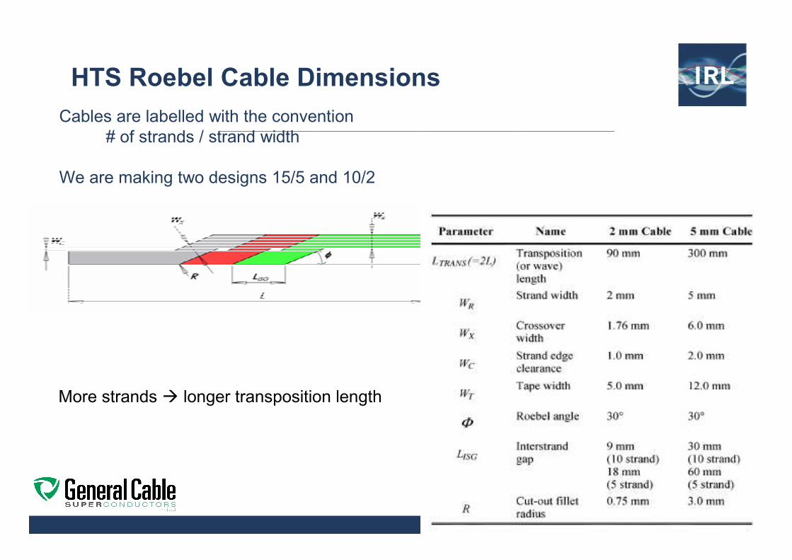
HTS Roebel Cable Dimensions
Cables are labelled with the convention# of strands / strand width
We are making two designs 15/5 and 10/2
More strands longer transposition length

Wire qualification
0 10 20 30 40 500.90
0.92
0.94
0.96
0.98
1.00
Co
rre
latio
nPosition (m)
Wire 2
∑ ∑∑
−−
−−=
22 )()(
))((),(
yyxx
yyxxYXCorrel
For Roebel we require 2D uniformity
- Scan wire magnetically (penetrated or remnant field)
- Quantify uniformity using statistical correlation with an ideal magnetic profile
Correlation along a length of YBCO wire, a minimum Correlcan be specified for input wire
Where |Correl | ≤ 1 X is a dataset representing calculated field
Yy1…yj is magnetic data across tape
0.000 T
200mm
(a)(a)0.023 T
(b)
Use magnetic imaging to assess tape quality (a)
tape with a known defect, and (b) tape with only
small scale variability.
0 2 4 6 8 10 120.010
0.015
0.020
0.025
0.030
0.035
0.040 cor_0.99 cor_0.90 cor_0.75
Fie
ld (
T)
Position (mm)
Example Profiles
Some wire is extremely good !
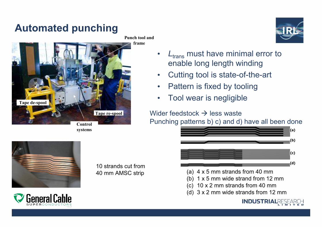
Automated punching
• Ltrans must have minimal error to enable long length winding
• Cutting tool is state-of-the-art
• Pattern is fixed by tooling
• Tool wear is negligible
Punch tool and
frame
Tape de-spool
Tape re-spool
Control
systems (a)
(b)
(c)
(d)
(a) 4 x 5 mm strands from 40 mm (b) 1 x 5 mm wide strand from 12 mm(c) 10 x 2 mm strands from 40 mm(d) 3 x 2 mm wide strands from 12 mm
10 strands cut from 40 mm AMSC strip
Wider feedstock less wastePunching patterns b) c) and d) have all been done

Quality of punching
Electroplated copper/NiW
Electroplated copper/NiW
AMSC 4 ply Cu/2x NiW/Cu
AMSC 3 ply SS/NiW/SS

Retained Ic
• Strands maintain the wire performance
– (Ic strand) / (Ic wire) ~ typically 90-95%, can be 110%
• High minimum value of Correl is necessary but not sufficient condition
∆Ic also needs to be considered
Length of defect important
Scaling to low T, defects look like a cross sectional loss of conductor
• Can we mitigate low Correl values?
– Strand reinforcement is OK for high I/Ic
Added section of wire (soldered)
defect

Automated Cable Winding
• Planetary wind– Longitudinal phase
very important
– Set up is important
– Every wire guided carefully into place
• In principle can be fast ~ meters/min
• At present we go slow– We have $$$ at risk
Automated planetary wind system for 15/5 cable

Current contacts
HTS Surface down-Direct contact with largest copper cross section
Apply solder with excess to fill interstrand gap
• Place cable in copper block• Apply solder to excess• Heat and apply pressure to flow solder• Cool down, then remove pressure

Cable Ic test

15/5 cable from SuperPower wire
Ic measurement of cables
•Measured Ic has been close to expected Ic
• For short length cables accurate Ic measurement is difficult
• At 77K there are strong self-field effects
• Calculation using method of K Thakur et al, Physica C 471, 42-47
13721410209315/5 SRC0027, d = 100 µm
11091010161615/5 SRC0024, d = 100 µm
10331100 145415/5, d = 160 µm
359.1341.94269/2, d = 350 µm
339.1318.84269/2, d = 136 µm
220.1 203 2525/2
ComputedMeasured Design Ic
Cable Ic(A)Cable details

Expected Ic at high fields (15/5 cable)
The data is generated using the following
assumptions
• Self-field performance of wire is scaled to higher
fields using data from SuperPower
•We have assumed 280A/cm performance of wire
(most current wires from SP meet or exceed this
performance).
• Note the design current will be significantly
reduced by the cable self field at fields < 1T
• 15/5 = 15 strands of 5mm width
•We do not have parallel field data at this time,
parallel field Ic is generally much higher than
perpendicular field performance e.g. see
http://www.htspeerreview.com/2008/pdfs/presentat
ions/tuesday/joint/joint_2_scale_up_progress_supe
rpower.pdf
0 5 10 15100
1000
10000
I c (
A)
Perpendicular Field (T)
4.2K, 14K, 22K, 33K 45K, 50K, 65K

Ic – longitudinal stress test
• 5/2 cable failed catastrophically at 453N (whilst still displaying 86% of maximum Ic)
• Roebel cable appears to exhibit identical ductile limit to Hastelloytape
– The Roebel strands lock together suppressing torque at the transpositions
• Increasing the tensile strain greatly improves current sharing between strands (data not shown).
Tensile ductile limit of Hastelloy276 ~ 700MPa @77K .From Clickner et al. Cryogenics 46 432-438 (2006)

The magnetization loss with the applied field
Cable coupled by copper bridges R ~ 10 µΩµΩµΩµΩ
1 10 1001
2
3
4
5
6
7
Γ (
J m
-1 c
ycle
-1str
and
-1 T
-2)
B (mT)
30 Hz 59.5 Hz 120 Hz 175.5 Hz
0 50 100 150 2000
2
4
6
Γ (
J m
-1 c
ycle
-1 s
tra
nd
-1 T
-2)
Frequency (Hz)
5/2 coupled cableB = 2 mT
The magnetization loss v frequency
Loss increasing then decreasing with frequencyFit to Debye form
Strand coupling

Strand insulation
Individual strands can be insulated with polymer coating to prevent current sharing
Roll coater to insulate strands

Cable insulation
Extrusion coating: fluorinated polymer Wrapping: kapton, nomex paper
No in situ processing of wire flexible insulation options

Conclusions
• We have established a pilot plant with automated production of 10/2 and 15/5 cable
• Demonstrated strand coupling and strand insulation
• Obtained first results on stress-Icproperties
• Magnetisation and transport AC loss results published
• Measurements on coil properties including AC loss in progress
• Likely route to low cost Roebelcable is through manufacture of wide REBCO strip Cable manufacture equipment at IRL site