Embed Size (px)
Citation preview
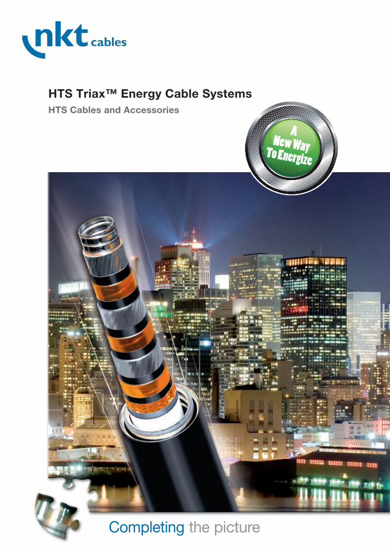
HTS Triax™ Energy Cable SystemsHTS Cables and Accessories
ANew Way To Energize

2
HTS Triax™ Energy Cable Systemsworld’s leading companies in the design,
manufacture and marketing of low, medium
and high-voltage cables and accessories. In
addition, with its workforce of 3000 employ-
ees this European high-tech corporation has
been making history in energy technology for
more than 130 years now. No wonder then
that nkt cables has also led the market in
researching and producing superconductive
cables from the very beginning. As early as
2001 the fi rst superconductive cable was
put into operation in a public power supply
network in Copenhagen. At the time a total of
50,000 households and companies benefi ted.
In future it will be millions.
High-temperature superconductor tech-
nology (HTS) is the key technology for
tomorrow’s electricity market. Compared
with copper conductors, HTS ceramic cables
have a number of signifi cant advantages. For
example they can conduct electric current
without resistance at app. 200°C below
zero. Transmission capacity is fi ve times
higher than that of conduc-tors made of
copper, while current loss is reduced to one
tenth. The development of HTS cables is
in-separably linked to the name nkt cables.
However, nkt cables is not just one of the
Property/Um/kV NT NE LV 10 15 36 72.5 150
PE-insulated, single phase X X D D
Coaxial, single phase X X D D D
Triax, three phase X X X X D D
Specialty conductors X (X) D D
NT: No Thermal Load, NE: No EMF, LV: Low Voltage specialty conductors, X: available, D: under development
Product Scope
HTS cables can be confi gured in several ways using the same materials and production processes. The most effi cient and high-performing
confi guration for the medium-voltage (MV) up to 72 kV is the HTS Triax™ design. nkt cables also has experience in coaxial single-phase
cables which are suitable for higher voltages. The HTS cable conductors can also be supplied with a conventional warm PE insulation.
nkt cables continually develops the voltage rating and the performance within the product scope described in the following table. nkt cables
offers cable conductors made from the 1st generation Bi2Sr2Ca2Cu3OX superconductors, while also working on integrating the new 2nd gene-
ration superconductors based on Y(RE)Ba2Cu3OX materials into these cable designs.“
Ultera® – helping to create the breakthrough
for HTS technologyThe potential of HTS technology is immense.
It is not just that energy suppliers no longer
lose unnecessary energy during transmission
across their extensive networks. Motors, ge-
nerators and transformers with HTS conduc-
tors are also much smaller, and achieve the
same output at much lower energy consump-
tion. For business the use of HTS technology
will mean long-term savings worth billions.
For people it is the future purely and simply.
In order to assist the HTS technology to
achieve its commercial break-through and
transform it as quickly as possible into
effective long-term solutions, nkt cables
and America’s biggest cable manufacturer
Southwire Company established the Ultera®
joint venture in 2002. Just like nkt cables,
Southwire is also an innovator and pioneer in
the fi eld of superconductor technology.
If the actual length of the cooperation
between the two companies is taken into
account, Ultera® now has ten years of practi-
cal experience in the daily provision of HTS
cables for energy supply in Europe and North
America. Together they represent the three
most successful installations worldwide with
HTS cables, thus opening the door wide to a
new way to energize.
®
HTS Cables with BSCCO tapes, copper stabiliser, Cryofl ex® dielectric, semifl exible cryostat
3
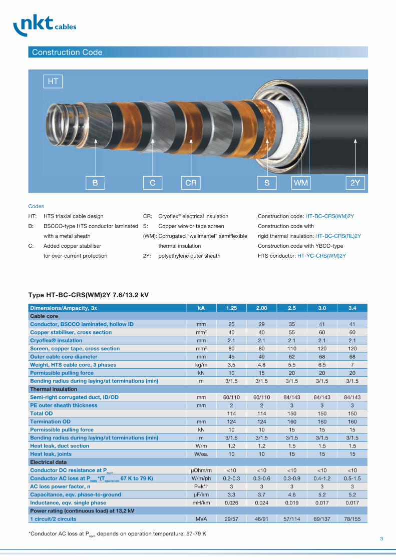
Codes
HT: HTS triaxial cable design
B: BSCCO-type HTS conductor laminated
with a metal sheath
C: Added copper stabiliser
for over-current protection
BB CC CRCR SS WMWM 2Y2Y
Construction Code
Type HT-BC-CRS(WM)2Y 7.6/13.2 kV
Dimensions/Ampacity, 3x kA 1.25 2.00 2.5 3.0 3.4
Cable core
Conductor, BSCCO laminated, hollow ID mm 25 29 35 �1 �1
Copper stabiliser, cross section mm2 �0 �0 55 60 60
Cryofl ex® insulation mm 2.1 2.1 2.1 2.1 2.1
Screen, copper tape, cross section mm2 80 80 110 120 120
Outer cable core diameter mm �5 �9 62 68 68
Weight, HTS cable core, 3 phases kg/m 3.5 �.8 5.5 6.5 7
Permissible pulling force kN 10 15 20 20 20
Bending radius during laying/at terminations (min) m 3/1.5 3/1.5 3/1.5 3/1.5 3/1.5
Thermal insulation
Semi-right corrugated duct, ID/OD mm 60/110 60/110 8�/1�3 8�/1�3 8�/1�3
PE outer sheath thickness mm 2 2 3 3 3
Total OD 11� 11� 150 150 150
Termination OD mm 12� 12� 160 160 160
Permissible pulling force kN 10 10 15 15 15
Bending radius during laying/at terminations (min) m 3/1.5 3/1.5 3/1.5 3/1.5 3/1.5
Heat leak, duct section W/m 1.2 1.2 1.5 1.5 1.5
Heat leak, joints W/ea. 10 10 15 15 15
Electrical data
Conductor DC resistance at Pnom µOhm/m <10 <10 <10 <10 <10
Conductor AC loss at Pnom *(Toperation 67 K to 79 K) W/m/ph 0.2-0.3 0.3-0.6 0.3-0.9 0.�-1.2 0.5-1.5
AC loss power factor, n P=k*ln 3 3 3 3 3
Capacitance, eqv. phase-to-ground µF/km 3.3 3.7 �.6 5.2 5.2
Inductance, eqv. single phase mH/km 0.026 0.02� 0.019 0.017 0.017
Power rating (continuous load) at 13,2 kV
1 circuit/2 circuits MVA 29/57 �6/91 57/11� 69/137 78/155
Construction code: HT-BC-CRS(WM)2Y
Construction code with
rigid thermal insulation: HT-BC-CRS(RL)2Y
Construction code with YBCO-type
HTS conductor: HT-YC-CRS(WM)2Y
CR: Cryofl ex® electrical insulation
S: Copper wire or tape screen
(WM): Corrugated “wellmantel” semifl exible
thermal insulation
2Y: polyethylene outer sheath
HT
*Conductor AC loss at Pnom depends on operation temperature, 67-79 K

�
Dimensions/Ampacity, 3x kA 1.25 2.00 2.5 3.0 3.4
Cable core
Conductor, BSCCO laminated, hollow ID mm 25 29 35 �1 �1
Copper stabiliser, cross section mm2 �0 �0 55 60 60
Cryoflex® insulation mm 3.� 3.� 3.� 3.� 3.�
Screen, copper tape, cross section mm2 120 120 120 120 120
Outer cable core diameter mm 57 61 67 73 73
Weight, HTS cable core, 3 phases kg/m � 5.2 6 7 7.5
Permissible pulling force kN 10 15 20 20 20
Bending radius during laying/at terminations (min) m 3/1.5 3/1.5 3/1.5 3/1.5 3/1.5
Thermal insulation
Semi-rigid corrugated duct, ID/OD mm 8�/1�3 8�/1�3 8�/1�3 98/163 98/163
PE outer sheath thickness mm 3 3 3 3 3
Total OD 150 150 150 170 170
Termination OD mm 160 160 160 180 180
Permissible pulling force kN 15 15 15 20 20
Bending radius during laying/at terminations (min) m 3/1.5 3/1.5 3/1.5 �/2 �/2
Heat leak, duct section W/m 1.5 1.5 1.5 1.7 1.7
Heat leak, joints W/ea. 10 10 15 15 15
Electrical data
Conductor DC resistance at Pnom µOhm/m <10 <10 <10 <10 <10
Conductor AC loss at Pnom*(Toperation 67 K to 79 K) W/m/ph 0.2-0.3 0.3-0.6 0.3-0.9 0.�-1.2 0.5-1.5
AC loss power factor, n P=k*ln 3 3 3 3 3
Capacitance, eqv. phase-to-ground µF/km 2.2 2.� 2.7 3.0 3.0
Inductance, eqv. single phase mH/km 0.032 0.029 0.025 0.022 0.022
Power rating (continuous load) at 30 kV
1 circuit/2 circuits MVA 65/130 10�/208 130/260 156/312 177/35�
Type HC-BC-CRS(WM)2Y 21/36 kV
*Conductor AC loss at Pnom depends on operation temperature, 67-79 K
Dimensions/Ampacity, 3x kA 1.25 2.00 2.5 3.0 3.4
Cable Core
Conductor, BSCCO laminated, hollow ID mm 25 29 35 �1 �1
Copper stabiliser, cross section mm2 �0 �0 55 60 60
Cryoflex® insulation mm �,7 �,7 �,7 �,7 �,7
Screen, copper tape, cross section mm2 120 120 120 120 120
Outer cable core diameter mm 65 69 75 81 81
Weight, HTS cable core, 3 phases kg/m �.5 5.8 6.5 7.5 8
Permissible pulling force kN 10 15 20 20 20
Bending radius during laying/at termination (min) m 3/1,5 3/1,5 3/1,5 3/1,5 3/1,5
Thermal Insulation
Semi-rigid corrugated duct, ID/OD mm 8�/1�3 8�/1�3 8�/1�3 98/163 98/163
PE outer sheath thickness mm 3 3 3 3 3
Total OD 150 150 150 170 170
Termination OD mm 160 160 160 180 180
Permissible pulling force kN 15 15 15 20 20
Bending radius during laying/at termination (min) m 3/1,5 3/1,5 3/1,5 �/2 �/2
Heat leak, duct section W/m 1,5 1,5 1,5 1,7 1,7
Heat leak, joints W/ea. 10 10 15 15 15
Electrical Data
Conductor DC resistance at Pnom µOhm/m <1 <1 <1 <1 <1
Conductor AC loss at Pnom W/m/ph 0.3 0.6 0.9 1.2 1.5
AC loss power factor, n P=k*ln 3 3 3 3 3
Capacitance, eqv. phase-to-ground µF/km 1,6 1,7 2,0 2,2 2,2
Inductance, eqv. single phase mH/km 0,039 0,036 0,031 0,028 0,028
Power Rating (continuous load) at 50 kV
1 circuit/2 circuits MVA 108/217 173/3�6 217/�33 260/520 29�/589
Type HT-BC-CRS(WM)2Y 42/72 kV HTS Triax™ Energy Cable

5
nkt cables sells and installs the HTS Terminations and joints. We can also specify and source the cooling system as well as the monitoring
system.
nkt cables sells and installs the HTS Terminations and joints. We can also specify and source the cooling system as well as the monitoring
system.
15 kV
Triax Terminations
15 kV
Triax Joint
JointsA 15 kV HTS Triax™ joint is 3 m long with an
outer diameter of 31 cm. It contains the joints
of all three phases and a common screen.
TerminationsA 15 kV HTS Triax™ termination is 3.9 m
long. The main body is installed at a height
that gives the appropriate safety distance to
the top bolts. The picture shows an outdoor
version of the termination. nkt cables will
convert this termionation to an indoor version
on customer request.
Product Scope
Accessories
Contents Joints 5
Terminations 5
Cooling System 6
Monitoring System 7
High-current Switchgear 7

6
Terminal Cooling Station
Line Cooling Station
Terminal Cooling StationTerminal Cooling Station
Line Cooling StationLine Cooling StationLine Cooling Station
Terminal Cooling Station
Terminal Cooling Station Line Cooling Station
Cooling SystemThe following cooling solutions have been
developed with Praxair Inc. The reliability
of the cable cooling system is guaranteed
through the following three features:
Redundant cooling machines in a
matrix of coolers
Eight hours of backup in a
cold storage tank
Continuous 2�/7 advanced surveillance
by a cooler operations center
The cooling power can be divided between
one or several cooling stations. The emer-
gency backup features are located in the
terminal cooling stations. The line cooling
stations are compact units of active coolers
that can be placed at intermediate locations
along the line. The distance between cooling
stations depends on the available cross sec-
tion for pumping the cooling fl uid. Distances
of 2-6 km are possible for compact sys-
tems. Closer spacing of the cooling stations
improves the energy effi ciency of the cable
systems but requires supply- and service-
points at several locations along the line.
The matrix of coolers consists of N+1
or N+2 closed-cycle, low-maintenance coo-
ling units. Cooling solutions can be develo-
ped together with major cryogenics system
suppliers to fi t individual user requirements.

7
These data are treated and analyzed automa-
tically. The cable system operator is supplied
with one of four simple status commands:
0 – zero: The cable system is under
service – Do not energize
1 – “Green”: The cable system is ready
to operate
Monitoring SystemThe HTS Triax™ Energy Cable is monitored
2� h per day, 7 days a week by an advanced
surveillance system. The surveillance system
collects data on temperature, pressure and
fl ow of the cooling medium, the temperatures
of the terminations and joints load and the
operastional status of the cooling machinery
and back-up systems.
High-current Switchgearnkt cables can facilitate contacts to switchgear suppliers. The following are examples of commercially available switchgear products
from various suppliers (2007).
Examples A B C D E F G H
Type Indoor Indoor Indoor Indoor Indoor Outdoor Outdoor Outdoor
Model HVX VAH VAH VD� HD� PMI SPS2 PMI
Ventilation passive passive active active passive passive passive passive
Rated voltage kV 15 17.5 17.5 12* 2� 72 15** 1�5***
Rated current, max. A 3000 �000 8000 �000 3600 3000 �000 �000
Short-circuit, max. kA �0/50 50 50 63 �0 �0 31/�0 �0/63
BIL kV 95 95 95 125 350 110 650
making time ms 5� 90 90 7�
breaking time ms �2 �5 �5 58 �5 60 60
*available in 12, 1�.5, 36 and �0.5 kV models
**available in 15, 25,38, �8and 78 kV models
***available in 121, 1�5 and 170 kV models
2 – “Yellow”: Malfunction – Manually
disconnect w/o customer
interruption
3 – “Red”: Urgent malfunction –
Automatic disconnect with
customer interruption
The service provider can perform remote dia-
gnostics through an advanced monitoring sys-
tem with complete access to all system sensors.
8
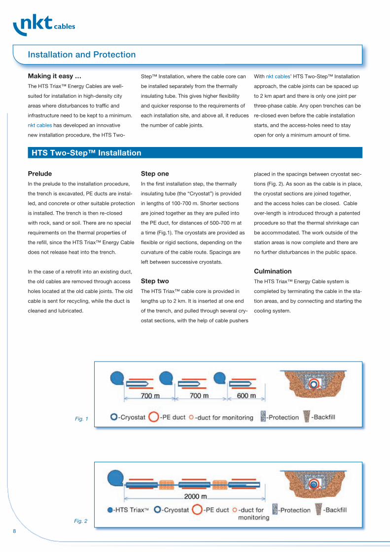
Making it easy …The HTS Triax™ Energy Cables are well-
suited for installation in high-density city
areas where disturbances to traffi c and
infrastructure need to be kept to a minimum.
nkt cables has developed an innovative
new installation procedure, the HTS Two-
PreludeIn the prelude to the installation procedure,
the trench is excavated, PE ducts are instal-
led, and concrete or other suitable protection
is installed. The trench is then re-closed
with rock, sand or soil. There are no special
requirements on the thermal properties of
the refi ll, since the HTS Triax™ Energy Cable
does not release heat into the trench.
In the case of a retrofi t into an existing duct,
the old cables are removed through access
holes located at the old cable joints. The old
cable is sent for recycling, while the duct is
cleaned and lubricated.
Step™ Installation, where the cable core can
be installed separately from the thermally
insulating tube. This gives higher fl exibility
and quicker response to the requirements of
each installation site, and above all, it reduces
the number of cable joints.
Step oneIn the fi rst installation step, the thermally
insulating tube (the “Cryostat”) is provided
in lengths of 100-700 m. Shorter sections
are joined together as they are pulled into
the PE duct, for distances of 500-700 m at
a time (Fig.1). The cryostats are provided as
fl exible or rigid sections, depending on the
curvature of the cable route. Spacings are
left between successive cryostats.
Step twoThe HTS Triax™ cable core is provided in
lengths up to 2 km. It is inserted at one end
of the trench, and pulled through several cry-
ostat sections, with the help of cable pushers
placed in the spacings between cryostat sec-
tions (Fig. 2). As soon as the cable is in place,
the cryostat sections are joined together,
and the access holes can be closed. Cable
over-length is introduced through a patented
procedure so that the thermal shrinkage can
be accommodated. The work outside of the
station areas is now complete and there are
no further disturbances in the public space.
Culmination The HTS Triax™ Energy Cable system is
completed by terminating the cable in the sta-
tion areas, and by connecting and starting the
cooling system.
With nkt cables’ HTS Two-Step™ Installation
approach, the cable joints can be spaced up
to 2 km apart and there is only one joint per
three-phase cable. Any open trenches can be
re-closed even before the cable installation
starts, and the access-holes need to stay
open for only a minimum amount of time.
Fig. 1
Fig. 2
Installation and Protection
HTS Two-Step™ Installation

9
To sum it up: Making use of nkt cables’
expertise and engineering assistance already
in the design stage, is the fi rst step for
smooth realization of the project.
A smaller parallel duct is installed near the
cryostat. Optical fi bres are pulled into the
duct and used for distributed temperature
sensing. Any damage to, or degradation in
the cryostat will show up as a temperature
signal at the location of the damage.
Optionally, some of the fi bres can be used for
communication. Fibres for thermal monitoring
can be provided as external skid wires in the
case of a retrofi t into an existing duct where
no parallel duct is available.
Service ContractsService contracts are offered where the task
of maintaining the cable installations in good
condition is transferred to the shoulders of
nkt cables. With this offer it is ensured that
skilled personnel takes care of the supercon-
ducting cables. Regular checks of the condi-
tions and, if necessary, initiation of remedial
action at an early stage guarantee the value
of the assets.
Thermal Monitoring and Damage Detection
Engeneering assistancenkt cables can provide advanced enginee-
ring services already in the early planning
stage of a project. Our engineers can provide
electrical data, thermal simulations and
proposed cable-system layouts as a part
of early system studies to evaluate the best
cable solutions. Making use of nkt cables’ ex-
pertise and engineering assistance already in
the design stage is the fi rst step for a smooth
realization of your project.

10
Testing of cables and accessories com-
prises routine and special tests performed
in the factory as well as tests on site after
completion of the installation. These tests
are performed in compliance with customer
requirements and various national and inter-
national standards like IEC, EN, VDE, NF, BS,
NEN, AEIC and others.
Type tests and long-term tests have been
made on components and also for qualifi ca-
tion of complete cable systems. Newly devel-
op ed cables and accessories are subjected
to tests in the fi eld lasting several years and
comprising electrical and thermal stressing
far beyond of what can be expected during
normal operation.
A complete recycling conceptfor all recyclable cable types By virtue of �0 years of experience within cable
recycling, we are the only European cable
manufacturer with a complete recycling con-
cept for all recyclable cable types. We recycle
cable waste at our environmentally approved
recycling plant in Stenlille. Our plant in Stenlille
is among the fi rst 100 Danish companies with
DS/EN ISO 1�001 certifi cation.
We take our environmental responsibility
seriously, for which reason environmental
considerations play an important role in all
departments of our company, irrespective of
it being a question of product development,
production or working processes or removal
of worn-out products.
For us it is not only a question of considering
the environment when recycling and recover-
ing cable waste. Environmental considerations
are also decisive in our selection of materials
and suppliers as well as in the planning of
production processes. In this way we minimize
the environmental impact related to the pro-
duct life cycle: production - use - removal.
Of course we also assist our customers to
act in the best interest of the environment.
Please contact us to learn how you can best
dispose of your cable waste.
Quality from beginning to end Quality from beginning to end is an essential
part of nkt cables’ manufacturing philosophy.
This is ensured by a combination of certifi ed
quality control throughout the production
process and the use of raw material from
approved sub-suppliers only. This places
nkt cables in a fi ne position in international
competition and secures fl exibility to adapt
rapidly to changing market requirements.
nkt cables is of course certifi ed according to
ISO 9001.
We know how nkt cables’ laboratory researches in and
develops environmentally sustainable plastic
materials for cables and leads and also
handles quality control of raw materials and
fi nished goods. The HV laboratories perform
electrical tests on the cables.
nkt cables’ technicians are internationally
recognized for their specialized knowledge in
compound development. nkt cables was the
fi rst company in the world to introduce lead-
free PVC cables in which the poisonous lead
stabilizers had been replaced by the relatively
harmless calcium and zinc stabilizers. The
idea was so good that the Danish Minister for
Environment and Energy prohibited marke-
ting cables with leaded PVC after December
1, 2001. Research plays an important role
in all parts of nkt cables. Recently, NKT
Research, nkt cables’ sister company, carried
out revolutionary research in materials tech-
nology. This research enabled nkt cables to
begin the production of fi bre optical cables
as early as in 1980 and to put the world’s
fi rst superconducting HV cable in a public
network in 2001.
Testing
Research & Development & Innovation

11
Quality Assurance and Environmental Responsibility
12
nkt
00.2
9.1.
0.
2.20
00
11.0
8 K
.F.C
. si
ebel
nkt cables GmbH
Schanzenstraße 6 – 20
D-51063 Cologne (Germany)
Phone +�9 (0)2 21- 676-0
Fax +�9 (0)2 21- 676-26�6
www.nktcables.com
Direct contact for your region:
Central EuropeCarsten Wolff
Phone +�9 (0)2 21- 676 -20 31
Representation offices
Belgium: +32 / �76 981 �29
Netherlands: +31 / 6�6095035
France: +33 / 616 12 15 ��
Scandinavia and UKBrian Scott
Phone +�5 / 5966 1213
Representation office
GB: +�� / 783�0 569 28
InternationalHans Damm Jensen
Phone +�9 (0)2 21- 676 -20 76
Representation offices
Moscow: +7 (�95) 777�858
UAE: +971 2 ��93550
nkt cables Spain S. L.Edifici Testa
Alcalde Barnils 6�-68
escal B, 3º piso, local 3
Sant Cugat del Valles
E-0817� Barcelona, Spain
Phone: +3� / 93 59 07 017
Fax: +3� / 93 67 50 528