Embed Size (px)
Citation preview

Installation and Operation Manual
3161 Governor
Electric Shutdown Device for the 3161 Governor (Energize to Shutdown/Energize to Run)
Manual 03105 (Revision B)

WARNING—DANGER OF DEATH OR PERSONAL INJURY
WARNING—FOLLOW INSTRUCTIONS Read this entire manual and all other publications pertaining to the work to be performed before installing, operating, or servicing this equipment. Practice all plant and safety instructions and precautions. Failure to follow instructions can cause personal injury and/or property damage.
WARNING—OUT-OF-DATE PUBLICATION This publication may have been revised or updated since this copy was produced. To verify that you have the latest revision, be sure to check the Woodward website:
www.woodward.com/pubs/current.pdf The revision level is shown at the bottom of the front cover after the publication number. The latest version of most publications is available at:
www.woodward.com/publications If your publication is not there, please contact your customer service representative to get the latest copy.
WARNING—OVERSPEED PROTECTION The engine, turbine, or other type of prime mover should be equipped with an overspeed shutdown device to protect against runaway or damage to the prime mover with possible personal injury, loss of life, or property damage. The overspeed shutdown device must be totally independent of the prime mover control system. An overtemperature or overpressure shutdown device may also be needed for safety, as appropriate.
WARNING—PROPER USE Any unauthorized modifications to or use of this equipment outside its specified mechanical, electrical, or other operating limits may cause personal injury and/or property damage, including damage to the equipment. Any such unauthorized modifications: (i) constitute "misuse" and/or "negligence" within the meaning of the product warranty thereby excluding warranty coverage for any resulting damage, and (ii) invalidate product certifications or listings.
CAUTION—POSSIBLE DAMAGE TO EQUIPMENT OR PROPERTY
CAUTION—BATTERY CHARGING To prevent damage to a control system that uses an alternator or battery-charging device, make sure the charging device is turned off before disconnecting the battery from the system.
CAUTION—ELECTROSTATIC DISCHARGE Electronic controls contain static-sensitive parts. Observe the following precautions to prevent damage to these parts. • Discharge body static before handling the control (with power to the control turned off,
contact a grounded surface and maintain contact while handling the control). • Avoid all plastic, vinyl, and Styrofoam (except antistatic versions) around printed circuit
boards. • Do not touch the components or conductors on a printed circuit board with your hands
or with conductive devices.
IMPORTANT DEFINITIONS • A WARNING indicates a potentially hazardous situation which, if not avoided, could result in
death or serious injury. • A CAUTION indicates a potentially hazardous situation which, if not avoided, could result in
damage to equipment or property. • A NOTE provides other helpful information that does not fall under the warning or caution
categories. Woodward Governor Company reserves the right to update any portion of this publication at any time. Information provided by Woodward Governor Company is believed to be correct and reliable. However, no responsibility is assumed by Woodward Governor Company unless otherwise expressly undertaken.
© Woodward 1983 All Rights Reserved

Manual 03105 3161 Electric Shutdown Device
Woodward i
Contents
CHAPTER 1. GENERAL INFORMATION........................................................... 1 Introduction.............................................................................................................1 Description..............................................................................................................1 Energize to Shutdown Version ...............................................................................1 Energize to Run Version ........................................................................................1 References .............................................................................................................2 CHAPTER 2. INSTALLATION.......................................................................... 3 Introduction.............................................................................................................3 Shutdown Nut Adjustment......................................................................................3 Installation Procedure.............................................................................................4 CHAPTER 3. REPAIR AND TEST PROCEDURES.............................................. 8 Introduction.............................................................................................................8 Troubleshooting for ETS Electric Shutdown Device ..............................................8 Troubleshooting for ETR Electric Shutdown Device ..............................................9 Electric Solenoid and Diode Test ...........................................................................9 Disassembly .........................................................................................................11 Cleaning ...............................................................................................................12 Part Inspection......................................................................................................12 Assembly ..............................................................................................................12 Assembly Procedure for ETS Version..................................................................13 Assembly Procedure for ETR Version .................................................................14 Test Procedure .....................................................................................................15 CHAPTER 4. REPLACEMENT PARTS ........................................................... 16 Electric Shutdown Assembly ................................................................................16 CHAPTER 5. SERVICE OPTIONS ................................................................. 18 Product Service Options.......................................................................................18 Returning Equipment for Repair...........................................................................19 Replacement Parts ...............................................................................................20 How to Contact Woodward...................................................................................20 Engineering Services ...........................................................................................21 Technical Assistance............................................................................................22
Illustrations and Tables Figure 1-1. Outline of the 3161 Governor with Electric Shutdown Device............. ii Figure 1-2. Schematic of Electric Shutdown Device (Energize to Shutdown) .......2 Figure 1-3. Schematic of Electric Shutdown Device (Energize to Run).................2 Figure 2-1. Governor Cover ...................................................................................3 Figure 2-2. Electric Shutdown Device ....................................................................4 Figure 2-3. Electric Shutdown Device with Manual Shutdown...............................5 Figure 2-4. Electric Shutdown Device with Pressure Shutdown............................6 Figure 2-5. Electric Shutdown Device with Manual Shutdown and Pressure
Shutdown...........................................................................................7 Figure 3-1. Test Schematic for Electric Shutdown...............................................10 Figure 3-2. Removing Pin from Shutdown Housing.............................................11 Figure 3-3. Shutdown Plunger Adjustment (ETS) ................................................13 Figure 3-4. Shutdown Plunger Adjustment (ETR)................................................14 Figure 4-1. Parts for ETS Electric Shutdown Device ...........................................17 Figure 4-2. Parts for ETR Electric Shutdown Device ...........................................17

3161 Electric Shutdown Device Manual 03105
ii Woodward
Figure 1-1. Outline of the 3161 Governor with Electric Shutdown Device

Manual 03105 3161 Electric Shutdown Device
Woodward 1
Chapter 1. General Information
Introduction This manual describes the installation and operation of the Woodward Electric Shutdown Device available for installation on the 3161 governor.
Description The Electric Shutdown Device (Figure 2-2) is installed on top of the right front corner of the 3161 cover. The device is a solenoid that positions a shutdown lever and limit/shutdown pilot valve.
Energize to Shutdown Version As the solenoid is energized, the left end of the shutdown lever is raised, pivots on a pin, and lowers the right end of the lever onto the limit/shutdown pilot valve, resulting in governor shutdown (Figure 1-2).
Energize to Run Version As long as the solenoid is energized, the left side of the lever is forced down. Through the pivot pin, this keeps the right side of the lever lifted, so the shutdown is not engaged. When the solenoid is de-energized, the return spring forces the right side of the lever down, resulting in governor shutdown (Figure 1-3). The Electric Shutdown Device can be used by itself or in conjunction with Manual or Pressure Shutdown Devices, as shown in Figures 2-3, 2-4, and 2-5.
WARNING—OVERSPEED PROTECTION The Electric Shutdown Device must be used only as a normal shutdown device. A separate overspeed trip shutdown device must be added to provide overspeed protection.

3161 Electric Shutdown Device Manual 03105
2 Woodward
Figure 1-2. Schematic of Electric Shutdown
Device (Energize to Shutdown)
Figure 1-3. Schematic of Electric Shutdown Device
(Energize to Run)
References 03101 3161 Governor 03102 3161 Governor (product specification) 03103 3161 Governor, Manual Shutdown Device 03104 3161 Governor, Pressure Shutdown Device 03106 3161 Governor, Pneumatic Speed Setting Device (factory installed
only) 03107 3161 Governor, Speed Adjusting Motor with Manual Speed Adjustment
(factory installed only) 03108 3161 Governor, Air Pressure Fuel Limiter (factory installed only) 03109 3161 Governor, Load Limit Control (factory installed only) 25075 Storage of Mechanical-Hydraulic Controls

Manual 03105 3161 Electric Shutdown Device
Woodward 3
Chapter 2. Installation
Introduction This chapter covers the installation of the Electric Shutdown Device and the adjustments of the Shutdown Nut. The 3161 governor and the Electric Shutdown Device are precision instruments and should be handled carefully.
NOTE The Electric Shutdown Device was calibrated and tested at the factory. If the device was purchased for installation on a governor already in service, NO FURTHER ADJUSTMENT IS NECESSARY.
Shutdown Nut Adjustment Check the adjustment of the shutdown nut on governors that have been overhauled. Use the following steps. 1. Remove all dirt, grease, water or any other foreign material from the
governor cover. 2. Remove two 3/8 inch hex head 1/4-20 screws (1), shutdown cover plate (2),
and gasket (3) from the governor cover (Figure 2-1). Remove the shutdown device(s) if so equipped.
Figure 2-1. Governor Cover
WARNING—SHUTDOWN Rotate the output shaft of the governor to the minimum fuel position and adjust the prime mover linkage to cause shutdown.

3161 Electric Shutdown Device Manual 03105
4 Woodward
3. Start the prime mover. With the governor operating, place a straightedge across the opening in the cover and across the shutdown nut.
WARNING—START-UP Be prepared to make an emergency shutdown when starting the engine, turbine, or other type of prime mover, to protect against runaway or overspeed with possible personal injury, loss of life, or property damage. 4. Turn the nut counterclockwise until the governor just starts to cause
shutdown, then turn it one full turn clockwise.
Installation Procedure Electric Shutdown Device on Plain Cover Use this section when installing the Electric Shutdown Device on a plain cover (no other shutdown device already on the cover): 1. Remove two screws (1), shutdown cover plate (2), and cover plate gasket
(3), from the governor cover (Figure 2-1). 2. Refer to Figures 2-2 (Electric Shutdown Device), 4-1 (Parts for ETS Electric
Shutdown Device), and 4-2 (Parts for ETR Electric Shutdown Device). Place gasket (5) on the governor cover. Place the Electric Shutdown Device on the cover and secure it with three screws (4).
Figure 2-2. Electric Shutdown Device 3. Attach the diode (if provided) to the cover as shown in Figure 2-2. Thread
the electrical leads from the diode (16) up through the conduit fitting on the cover.
4. Install the shutdown cover plate and gasket on the Electric Shutdown
Device and secure it with two screws. Torque all 1/4-20 screws to 90 lb-in (10.2 N m).
PROCEED TO THE ELECTRIC SOLENOID AND DIODE TEST PROCEDURE IN CHAPTER 3.

Manual 03105 3161 Electric Shutdown Device
Woodward 5
Electric Shutdown Device with Manual Shutdown Use this section when installing the Electric Shutdown Device on a cover that has a Manual Shutdown already in place: 1. Remove two screws, and lift the Manual Shutdown and shutdown gasket
from the governor cover. 2. Refer to Figures 2-3 (Electric Shutdown Device with Manual Shutdown),
4-1 (Parts for ETS Electric Shutdown Device), and 4-2 (Parts for ETR Electric Shutdown Device). Place gasket (5) on the governor cover. Place the Electric Shutdown Device on the cover and secure it with three screws.
Figure 2-3. Electric Shutdown Device with Manual Shutdown 3. Attach the diode (16) to the cover as shown in Figure 2-3. Thread the
electrical leads from the diode up through the conduit fitting on the cover. 4. Install the Manual Shutdown with gasket on the Electric Shutdown Device
and secure it with two screws. Torque all 1/4-20 screws to 90 lb-in (10.2 N m).
PROCEED TO THE ELECTRIC SOLENOID AND DIODE TEST PROCEDURE IN CHAPTER 3. Electric Shutdown Device with Pressure Shutdown Use this section when installing the Electric Shutdown Device on a cover that has a Pressure Shutdown already in place: 1. Remove two screws, and lift the Pressure Shutdown and shutdown gasket
from the governor cover. 2. Refer to Figures 2-4 (Electric Shutdown Device with Pressure Shutdown),
4-1 (Parts for ETS Electric Shutdown Device), and 4-2 (Parts for ETR Electric Shutdown Device). Place gasket (5) on the governor cover. Place the Electric Shutdown Device on the cover and secure it with three screws.
3. Attach the diode (16) to the cover as shown in Figure 2-4. Thread the
electrical leads from the diode up through the conduit fitting on the cover.

3161 Electric Shutdown Device Manual 03105
6 Woodward
Figure 2-4. Electric Shutdown Device with Pressure Shutdown 4. Install the Pressure Shutdown and shutdown gasket on the Electric
Shutdown Device and secure it with two screws. Torque all 1/4-20 screws to 90 lb-in (10.2 N m).
PROCEED TO THE ELECTRIC SOLENOID AND DIODE TEST PROCEDURE IN CHAPTER 3. Electric Shutdown Device with Manual Shutdown and Pressure Shutdown Use this section when installing the Electric Shutdown Device on a cover that has both a Manual Shutdown and a Pressure Shutdown already in place: 1. Remove two screws from the Pressure Shutdown. Remove the Pressure
and Manual shutdowns as one unit. Remove the shutdown gasket. 2. Refer to Figures 2-5 (Electric Shutdown Device with Manual and Pressure
Shutdown), 4-1 (Parts for ETS Electric Shutdown Device), and 4-2 (Parts for ETR Electric Shutdown Device). Place gasket (5) on the governor cover. Place the Electric Shutdown Device on the cover and secure it with three screws.
3. Attach the diode (16) to the cover as shown in Figure 2-5. Thread the
electrical leads from the diode up through the conduit fitting on the cover. 4. Install the Manual and Pressure Shutdowns with shutdown gasket on the
Electric Shutdown Device. Secure them with two screws. Torque all 1/4-20 screws to 90 lb-in (10.2 N m).
PROCEED TO THE ELECTRIC SOLENOID AND DIODE TEST PROCEDURE IN CHAPTER 3.

Manual 03105 3161 Electric Shutdown Device
Woodward 7
Figure 2-5. Electric Shutdown Device with Manual Shutdown and Pressure Shutdown

3161 Electric Shutdown Device Manual 03105
8 Woodward
Chapter 3. Repair and Test Procedures
Introduction This chapter provides instruction for troubleshooting, repair, and calibration of the Electric Shutdown Device. Use the following troubleshooting guide to troubleshoot the Electric Shutdown Device. Determine first if you have an ETS (energize to shutdown) or ETR (energize to run) Electric Shutdown Device.
Troubleshooting for ETS Electric Shutdown Device This section describes troubleshooting for the ETS (energize to shutdown) Electric Shutdown Device. If the governor does not shut down the prime mover when the Electric Shutdown Device is energized, follow this procedure to correct the problem. Problem Action Is the correct voltage available to the shutdown? Is correct polarity observed?
Supply the correct voltage with the correct polarity (+ to red, – to black).
Is the shutdown nut on the limit/shutdown rod set correctly?
Readjust the shutdown nut. Refer to Chapter 2, Shutdown Nut Adjustment.
Is the solenoid set to allow the correct stroke of the solenoid plunger?
Reset the solenoid. Refer to Assembly Procedure, step 6.
Are the solenoid coil (14) and diode (16) functioning correctly? Refer to Electric Solenoid and Diode Test.
Replace the solenoid and diode if they are not functioning correctly.
Is the linkage from the governor to the prime mover set correctly?
Refer to the prime mover specifications for proper setting of the linkage.
If the governor does not allow the prime mover to start, follow this procedure to correct the problem. Problem Action Is the Electric Shutdown Device energized? If the Electric Shutdown Device is tied into
a failsafe system., be sure that no condition exists which calls for start prevention. If the Electric Shutdown Device is NOT part of a failsafe system, de-energize the shutdown device.
Is the shutdown nut adjusted correctly? Readjust the shutdown nut. Refer to Chapter 2, Shutdown Nut Adjustment.
Is the solenoid (14) adjusted correctly? Readjust the solenoid. Refer to Assembly Procedure, step 6.
Is the shutdown lever (8) adjusted correctly?
Readjust the shutdown lever. Refer to Assembly Procedure and Figure 3-3.
Is the shutdown linkage inside the governor stuck or binding?
Repair or adjust the linkage.
Is the linkage from the governor to the prime mover adjusted correctly?
Refer to the prime mover specifications for proper setting of the linkage.

Manual 03105 3161 Electric Shutdown Device
Woodward 9
Troubleshooting for ETR Electric Shutdown Device This section describes troubleshooting for the ETR (energize to run) Electric Shutdown Device. If the governor does not shut down the prime mover when the Electric Shutdown Device is de-energized, follow this procedure to correct the problem. Problem Action Is the shutdown nut on the limit/shutdown rod set correctly?
Readjust the shutdown nut. Refer to Chapter 2, Shutdown Nut Adjustment.
Is the solenoid set to allow the correct stroke of the solenoid plunger?
Reset the solenoid. Refer to Assembly Procedure, step 6.
Is the shutdown lever (8) adjusted to allow enough stroke to cause shutdown?
Adjust the lever adjustment screw (3). Refer to Figure 3-3.
Is the linkage from the governor to the prime mover set correctly?
Refer to the prime mover specifications for proper setting of the linkage.
If the governor does not allow the prime mover to start, follow this procedure to correct the problem. Problem Action Is the Electric Shutdown Device energized to the correct voltage? Is correct polarity observed?
If the Electric Shutdown Device is tied into a failsafe system., be sure that no condition exists which calls for start prevention. Check the part of the control system that controls the solenoid signal. Supply the correct voltage with the correct polarity (+ to red, – to black).
Is the shutdown nut adjusted correctly? Readjust the shutdown nut. Refer to Chapter 2, Shutdown Nut Adjustment.
Is the solenoid (14) adjusted correctly to allow the correct stroke of the solenoid plunger?
Readjust the solenoid. Refer to Assembly Procedure, step 6.
Is the shutdown lever (8) adjusted correctly to allow enough stroke to release the shutdown linkage?
Readjust the shutdown lever. Refer to Assembly Procedure and Figure 3-3.
Is the shutdown linkage inside the governor stuck or binding?
Repair or adjust the linkage.
Are the solenoid coil (14) and diode (16) functioning correctly? Refer to Electric Solenoid and Diode Test.
Replace the solenoid and diode if they are not functioning correctly.
Is the linkage from the governor to the prime mover adjusted correctly?
Refer to the prime mover specifications for proper setting of the linkage.
Electric Solenoid and Diode Test (See Figure 3-1.)
Before disassembling the Electric Shutdown Device, determine if the solenoid and diode are operational by doing the following test: 1. Disconnect the green and yellow leads from the power supply.

3161 Electric Shutdown Device Manual 03105
10 Woodward
2. Using an ohmmeter, connect the (+) positive lead to the yellow wire and the (–) negative lead to the green wire. The resistance should read 100 to 1000 Α. If it reads less than 100 or greater than 1000 Α, or if when the leads are reversed resistance is less than 20 kΑ, cut the white wires leading from the solenoid and proceed to steps A and B.
If resistance (as measured in step 2 above) is between 100 and 1000 Α,
reverse polarity and measure resistance. Resistance should be 20 kΑ to infinity. If resistance is less than 20 kΑ, cut the white wires leading from the solenoid and proceed to steps A and B.
NOTE Resistance measurements taken with high impedance meters (DVOMs, Fluke 8020A etc.) will read higher than the same measurements taken with low impedance meters (VOMs, Simpson 260, 270, etc). Step A (a) Measure resistance of the solenoid coil. (b) If coil resistance is less than 50 Α, replace the solenoid and diode. If coil
resistance is greater than 60 Α, replace the solenoid. (Refer to the Assembly Procedure, step 6, to install and adjust the new solenoid.)
Step B (a) Check for continuity between the (–) green and (–) #2 white wire. With (+)
positive lead on the yellow wire, and the (–) negative lead on the #1 white wire, measure and compare the reading when meter lead polarity is changed. Reading with (+) yellow and (–) #1 white should be low (40 to 1000 Α), and (–) yellow and (+) #1 white should be high (20 kΑ to infinity). If the readings are not within these limits, replace the diode.
(b) With (+) positive lead on the green wire and (–) negative lead on the #1
white wire, measure and compare the reading when meter lead polarity is changed. Reading with (+) green and (–) #1 white should be low (40 to 1000 Α) and (–) green and (+) #1 white should be high (20 kΑ to infinity). If the readings are not within these limits, replace the diode.
Figure 3-1. Test Schematic for Electric Shutdown

Manual 03105 3161 Electric Shutdown Device
Woodward 11
NOTE If the solenoid and diode have been checked and found to be functional, or have been replaced, further disassembly of the device may not be needed. If additional repair is necessary, proceed next to Disassembly. Before attempting the disassembly of the Electric Shutdown Device, remove all dirt, grease, water and other contaminants from the device.
WARNING—EYE PROTECTION Wear approved eye protection to prevent possible eye injury during disassembly, cleaning, and assembly of parts.
Disassembly (Refer to Figures 4-1 and 4-2.)
1. Turn the control switch to the OFF position. Disconnect the Electric
Shutdown Device from the power supply. 2. Remove the 3/8 inch hex head 1/4-20 screw (17) from the diode on the
governor cover. 3. Push the wire leads down through the conduit fitting. 4. Remove the shutdown cover plate and any other shutdown device from the
Electric Shutdown Device. 5. Remove three screws (4) and the Electric Shutdown Device from the
governor cover. 6. Refer to Figure 3-2. Press pin (1) from the shutdown housing (2). Remove
two washers (10) and the shutdown lever assembly.
Figure 3-2. Removing Pin from Shutdown Housing 7. For ETS (energize to shutdown) version, remove retaining ring (7) and
shutdown plunger (9). For ETR (energize to run) version, remove spring seat (21) and spring (22), then remove retaining ring (7) and shutdown plunger (9).

3161 Electric Shutdown Device Manual 03105
12 Woodward
8. For ETS version, remove cotter pin(s) (12), washer(s) (11), headed pins (6/20), and shutdown link (13). For ETR version, remove cotter pin (12), washer (11), headed pin (6), and roller (24).
Cleaning Clean parts with solvent and a stiff brush to remove foreign particles.
WARNING—SOLVENTS Follow the manufacturer’s instructions or restrictions regarding the use of solvents. If no instructions are available, handle with care. Use cleaning solvent in a well ventilated area away from fires or sparks. Dry parts with clean, lint-free wipes, or blow dry with clean dry air. Handle parts that have been machined to a close tolerance carefully, to prevent damage caused by contact with other parts or objects.
Part Inspection (Refer to Figures 4-1 and 4-2.)
Solenoid (14/19/25) and Diode (16). These parts were tested before disassembly began. No further testing is
required. Pin (1). Inspect pin (1) for wear in area of contact with lever (8). Headed Pins (6/20). Inspect pin(s) (6/20) for wear in the area of contact with shutdown link (13)
or roller (24). Shutdown Plunger (9). Inspect shutdown plunger for wear and damage in the area of contact with
shutdown nut. Solenoid Shutdown Link (13). Inspect link for wear or elongation of pin holes. Solenoid Shutdown Roller (24) Inspect roller for wear on OD from solenoid plunger and on ID from pin.
Assembly To prepare to assemble the Electric Shutdown Device, lay the parts in an orderly fashion on a clean dry work surface. Use only new gaskets and cotter pins. Careful and precise assembly methods will save time, and help to ensure correct operation of the shutdown. Torque all 1/4-20 screws to 90 lb-in (10.2 N m).

Manual 03105 3161 Electric Shutdown Device
Woodward 13
Assembly Procedure for ETS Version Refer to Figures 3-3 and 4-1, and do the following for the energize to shutdown version: 1. Connect one end of shutdown link (13) to the solenoid plunger with headed
pin (6), washer (11), and cotter pin (12) [old style solenoid], or using headed pin (20) only [new style solenoid].
2. Connect shutdown lever (8) to shutdown link (13) with headed pin (6),
washer (11), and cotter pin (12). 3. Install shutdown plunger (9) in shutdown lever (8) with retaining ring (7). Be
sure plunger moves freely in the lever. 4. Install the shutdown lever assembly in shutdown housing (2). Be sure
washers (10) are on pin (1) on each side of lever (8). Start and press pin in from the side shown in Figure 3-2.
Figure 3-3. Shutdown Plunger Adjustment (ETS) 5. Hold shutdown housing (2) against gasket (5) on a flat surface. Adjust set
screw (3) until plunger (9) just contacts the flat surface, then turn the set screw counterclockwise 1/4 turn.
6. Apply thread locking compound to the threads of shutdown solenoid (14/19).
Turn the solenoid in (clockwise) until it stops, then counterclockwise one turn. Tighten solenoid jam nut against shutdown housing (2). Torque to 45 to 55 lb-ft (61 to 75 N m).
7. Install gasket (5) and the shutdown device on the governor cover. Secure
with three screws (4). 8. Attach diode (16) (if used) to the governor cover with screw (17). Thread the
yellow and green wires up through the conduit fitting.
3161 Electric Shutdown Device Manual 03105
14 Woodward
Assembly Procedure for ETR Version Refer to Figures 3-4 and 4-2, and do the following for the energize to run version: 1. Assemble roller (24) to one end of the shutdown lever (23) with headed pin
(6), washer (11), and hitch pin (12). 2. Install shutdown plunger (9) in shutdown lever (23) with retaining ring (7).
Be sure plunger moves freely in the lever. Place spring (22) into socket in shutdown lever, and place the spring seat (21) in the inside of the hole in the shutdown housing (2) (align the cutout on the spring seat with the set screw socket in the shutdown housing).
Figure 3-4. Shutdown Plunger Adjustment (ETR) 3. Install the shutdown lever assembly in the shutdown housing (2), making
sure the spring seats into the spring seat. Be sure washers (10) are on pin (1) on each side of lever (23). Start and press pin in from the side shown in Figure 3-2.
4. Hold shutdown housing (2) against gasket (5) on a flat surface. Adjust set
screw (3) until plunger (9) just contacts the flat surface, then turn the set screw counterclockwise 1/4 turn.
5. Energize the solenoid. 6. Apply thread locking compound to the threads of shutdown solenoid (25).
Turn the solenoid clockwise until the shutdown lever touches the set screw. Turn the solenoid clockwise 1/4 additional turn. Tighten solenoid jam nut against shutdown housing (2). Torque to 45 to 55 lb-ft (61 to 75 N m).
7. Install gasket (5) and the shutdown device on the governor cover. Secure
with three screws (4). 8. Attach diode (16) (if used) to the governor cover with screw (17). Thread
yellow and green wires up through the conduit fitting.

Manual 03105 3161 Electric Shutdown Device
Woodward 15
Test Procedure Be sure the power supply to the shutdown is de-energized. Connect the Electric Shutdown Device to the power supply with polarity as shown in Figure 3-1.
WARNING—START-UP Be prepared to make an emergency shutdown when starting the engine, turbine, or other type of prime mover, to protect against runaway or overspeed with possible personal injury, loss of life, or property damage. With the overspeed shutdown device(s) correctly installed and operational, start the prime mover. 1. For ETS (energize to shutdown) solenoids: Energize the solenoid. The
governor output shaft should rotate to the minimum fuel position, causing prime mover shutdown.
2. For ETR (energize to run) solenoids: De-energize the solenoid. The
governor output shaft should rotate to the minimum fuel position, causing prime mover shutdown.
If shutdown does not occur, check the following: a. Shutdown nut adjustment. b. Correct installation of the Electric Shutdown Device. c. Correct adjustment of the fuel linkage from the governor output shaft to
the prime mover. d. Correct installation or adjustment of other shutdown devices used on the
governor (if any). 2. If the governor was equipped with other shutdown devices (pressure or
manual) prior to the installation of the Electric Shutdown Device, check these device(s) to be sure they are operational.
3161 Electric Shutdown Device Manual 03105
16 Woodward
Chapter 4. Replacement Parts
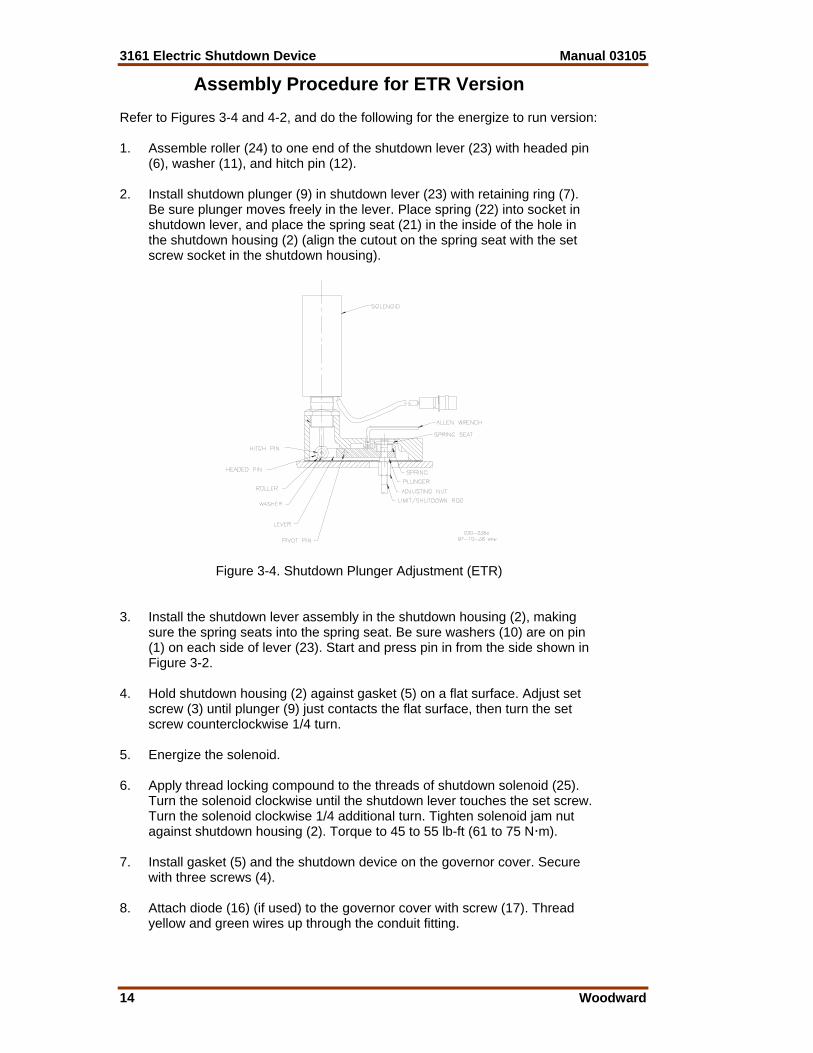
Electric Shutdown Assembly When ordering replacement parts, include the following information: • Manual number (this is manual 03105) • Governor part number and serial number shown on the nameplate • Part reference number and part name from parts list Ref. No. Part Name.......................................................... Quantity 03105-1 Pin ...................................................................................1 03105-2 Shutdown housing ...........................................................1 03105-3 Set screw 10-32 x .250 ....................................................1 03105-4 Screw 250-20 x 1.0 ..........................................................3 03105-5 Gasket .............................................................................1 03105-6 Headed Pin .124 x .531 ............1 (2 for old style solenoid) 03105-7 Retaining ring .225...........................................................1 03105-8 Shutdown lever .........................................1 (ETS version) 03105-9 Shutdown plunger ............................................................1 03105-10 Washer .203 x .438..........................................................2 03105-11 Washer .149 x .375...................1 (2 for old style solenoid) 03105-12 Cotter pin .062 dia x 375...........1 (2 for old style solenoid) 03105-13 Shutdown link ...........................................1 (ETS version) 03105-14 Solenoid 24 Vdc (old style) .......................1 (ETS version) 03105-15 Solenoid boot...................................................................1 03105-16 Diode (optional) ...............................................................1 03105-17 Screw .250-20 (for diode) ................................................1 03105-18 Connector ........................................................................2 03105-19 Solenoid 24 Vdc (new style)......................1 (ETS version) 03105-20 Headed Pin ....................... 1 (new style sol.; ETS version) 03105-21 Spring seat................................................1 (ETR version) 03105-22 Spring .......................................................1 (ETR version) 03105-23 Shutdown lever .........................................1 (ETR version) 03105-24 Roller ........................................................1 (ETR version) 03105-25 Solenoid 24 Vdc........................................1 (ETR version)

Manual 03105 3161 Electric Shutdown Device
Woodward 17
Figure 4-1. Parts for ETS Electric Shutdown Device
Figure 4-2. Parts for ETR Electric Shutdown Device

3161 Electric Shutdown Device Manual 03105
18 Woodward
Chapter 5. Service Options
Product Service Options The following factory options are available for servicing Woodward equipment, based on the standard Woodward Product and Service Warranty (5-01-1205) that is in effect at the time the product is purchased from Woodward or the service is performed: • Replacement/Exchange (24-hour service) • Flat Rate Repair • Flat Rate Remanufacture If you are experiencing problems with installation or unsatisfactory performance of an installed system, the following options are available: • Consult the troubleshooting guide in the manual. • Contact Woodward technical assistance (see “How to Contact Woodward”
later in this chapter) and discuss your problem. In most cases, your problem can be resolved over the phone. If not, you can select which course of action you wish to pursue based on the available services listed in this section.
Replacement/Exchange Replacement/Exchange is a premium program designed for the user who is in need of immediate service. It allows you to request and receive a like-new replacement unit in minimum time (usually within 24 hours of the request), providing a suitable unit is available at the time of the request, thereby minimizing costly downtime. This is also a flat rate structured program and includes the full standard Woodward product warranty (Woodward Product and Service Warranty 5-01-1205). This option allows you to call in the event of an unexpected outage, or in advance of a scheduled outage, to request a replacement control unit. If the unit is available at the time of the call, it can usually be shipped out within 24 hours. You replace your field control unit with the like-new replacement and return the field unit to the Woodward facility as explained below (see “Returning Equipment for Repair” later in this chapter). Charges for the Replacement/Exchange service are based on a flat rate plus shipping expenses. You are invoiced the flat rate replacement/exchange charge plus a core charge at the time the replacement unit is shipped. If the core (field unit) is returned to Woodward within 60 days, Woodward will issue a credit for the core charge. [The core charge is the average difference between the flat rate replacement/exchange charge and the current list price of a new unit.] Return Shipment Authorization Label. To ensure prompt receipt of the core, and avoid additional charges, the package must be properly marked. A return authorization label is included with every Replacement/Exchange unit that leaves Woodward. The core should be repackaged and the return authorization label affixed to the outside of the package. Without the authorization label, receipt of the returned core could be delayed and cause additional charges to be applied.

Manual 03105 3161 Electric Shutdown Device
Woodward 19
Flat Rate Repair Flat Rate Repair is available for the majority of standard products in the field. This program offers you repair service for your products with the advantage of knowing in advance what the cost will be. All repair work carries the standard Woodward service warranty (Woodward Product and Service Warranty 5-01-1205) on replaced parts and labor. Flat Rate Remanufacture Flat Rate Remanufacture is very similar to the Flat Rate Repair option with the exception that the unit will be returned to you in “like-new” condition and carry with it the full standard Woodward product warranty (Woodward Product and Service Warranty 5-01-1205). This option is applicable to mechanical products only.
Returning Equipment for Repair If a control (or any part of an electronic control) is to be returned to Woodward for repair, please contact Woodward in advance to obtain a Return Authorization Number. When shipping the item(s), attach a tag with the following information: • name and location where the control is installed; • name and phone number of contact person; • complete Woodward part number(s) and serial number(s); • description of the problem; • instructions describing the desired type of repair.
CAUTION—ELECTROSTATIC DISCHARGE To prevent damage to electronic components caused by improper handling, read and observe the precautions in Woodward manual 82715, Guide for Handling and Protection of Electronic Controls, Printed Circuit Boards, and Modules. Packing a Control Use the following materials when returning a complete control: • protective caps on any connectors; • antistatic protective bags on all electronic modules; • packing materials that will not damage the surface of the unit; • at least 100 mm (4 inches) of tightly packed, industry-approved packing
material; • a packing carton with double walls; • a strong tape around the outside of the carton for increased strength.
3161 Electric Shutdown Device Manual 03105
20 Woodward
Return Authorization Number When returning equipment to Woodward, please telephone and ask for the Customer Service Department [1 (800) 523-2831 in North America or +1 (970) 482-5811]. They will help expedite the processing of your order through our distributors or local service facility. To expedite the repair process, contact Woodward in advance to obtain a Return Authorization Number, and arrange for issue of a purchase order for the item(s) to be repaired. No work can be started until a purchase order is received.
NOTE We highly recommend that you make arrangement in advance for return shipments. Contact a Woodward customer service representative at 1 (800) 523-2831 in North America or +1 (970) 482-5811 for instructions and for a Return Authorization Number.
Replacement Parts When ordering replacement parts for controls, include the following information: • the part number(s) (XXXX-XXXX) that is on the enclosure nameplate; • the unit serial number, which is also on the nameplate.
How to Contact Woodward In North America use the following address when shipping or corresponding: Woodward Governor Company PO Box 1519 1000 East Drake Rd Fort Collins CO 80522-1519, USA Telephone—+1 (970) 482-5811 (24 hours a day) Toll-free Phone (in North America)—1 (800) 523-2831 Fax—+1 (970) 498-3058 For assistance outside North America, call one of the following international Woodward facilities to obtain the address and phone number of the facility nearest your location where you will be able to get information and service. Facility Phone Number Brazil +55 (19) 3708 4800 India +91 (129) 230 7111 Japan +81 (476) 93-4661 The Netherlands +31 (23) 5661111 You can also contact the Woodward Customer Service Department or consult our worldwide directory on Woodward’s website (www.woodward.com) for the name of your nearest Woodward distributor or service facility.

Manual 03105 3161 Electric Shutdown Device
Woodward 21
Engineering Services Woodward Industrial Controls Engineering Services offers the following after-sales support for Woodward products. For these services, you can contact us by telephone, by email, or through the Woodward website. • Technical Support • Product Training • Field Service Contact information: Telephone—+1 (970) 482-5811 Toll-free Phone (in North America)—1 (800) 523-2831 Email—[email protected] Website—www.woodward.com Technical Support is available through our many worldwide locations or our authorized distributors, depending upon the product. This service can assist you with technical questions or problem solving during normal business hours. Emergency assistance is also available during non-business hours by phoning our toll-free number and stating the urgency of your problem. For technical support, please contact us via telephone, email us, or use our website and reference Customer Services and then Technical Support. Product Training is available at many of our worldwide locations (standard classes). We also offer customized classes, which can be tailored to your needs and can be held at one of our locations or at your site. This training, conducted by experienced personnel, will assure that you will be able to maintain system reliability and availability. For information concerning training, please contact us via telephone, email us, or use our website and reference Customer Services and then Product Training. Field Service engineering on-site support is available, depending on the product and location, from one of our many worldwide locations or from one of our authorized distributors. The field engineers are experienced both on Woodward products as well as on much of the non-Woodward equipment with which our products interface. For field service engineering assistance, please contact us via telephone, email us, or use our website and reference Customer Services and then Technical Support.
3161 Electric Shutdown Device Manual 03105
22 Woodward
Technical Assistance If you need to telephone for technical assistance, you will need to provide the following information. Please write it down here before phoning: General Your Name Site Location Phone Number Fax Number Prime Mover Information Engine/Turbine Model Number Manufacturer Number of Cylinders (if applicable) Type of Fuel (gas, gaseous, steam, etc) Rating Application Control/Governor Information Please list all Woodward governors, actuators, and electronic controls in your system: Woodward Part Number and Revision Letter Control Description or Governor Type Serial Number Woodward Part Number and Revision Letter Control Description or Governor Type Serial Number Woodward Part Number and Revision Letter Control Description or Governor Type Serial Number If you have an electronic or programmable control, please have the adjustment setting positions or the menu settings written down and with you at the time of the call.


We appreciate your comments about the content of our publications.
Send comments to: [email protected]
Please include the manual number from the front cover of this publication.
PO Box 1519, Fort Collins CO 80522-1519, USA 1000 East Drake Road, Fort Collins CO 80525, USA Phone +1 (970) 482-5811 • Fax +1 (970) 498-3058
Email and Website—www.woodward.com
Woodward has company-owned plants, subsidiaries, and branches, as well as authorized distributors and other authorized service and sales facilities throughout the world.
Complete address / phone / fax / email information for all locations is available on our website.
06/5/F