Embed Size (px)
Citation preview
Searle Air Cooled Condensers, Dry Coolers and Gas cooler
INSTALLATION AND MAINTENANCE INSTRUCTIONS
Searle Air cooled Condenser , Dry Cooler and Gas cooler
INSTALLATION & MAINTENANCE INSTRUCTIONSContent : Important Information
1. Health and Safety2. Warranty Procedure3. Labelling on Condensers4. Packaging5. Legs and Loading6. Handling7. Storage 8. Installation and Location guidance 9. Pipework10. Evacuation11. Refrigerant Sub-cooling12. Refrigerants13. Fluid Cooler Applications - Fluid 14. Fluid Cooler Applications – Frost Protection 15. Electrical16. Condensers with Triac or Inverter Speed Control17. AC Fansets 18. EC Motors 19. Initial Starting 20. Maintenance 21. Coil Cleaning22. Standards 23. Invalidation of Guarantee24. Dimension drawings and tables
INTRODUCTIONThis installation and maintenance is intended to accompany Kelvion manufactured air cooled condens-er, Dry coolers and gas coolers. The ranges are made up of heat exchanger; commonly incorporating aluminium fin material and copper tube, galvanised steel casework and axial fan set. These components will vary with application, but the product function will remain common; to remove energy from a working fluid, generally as part of a refrigeration system. This document is not a replacement for formal training and should only be referenced by qualified personnel (meeting relevant regional standards). Any installation or maintenance work carried out in relation to the supplied air cooled condenser should be in accordance to regional / national law and legislation. Additional information and assistance can be provided by the equipment supplier or from the Kelvion regional offices located worldwide.
3
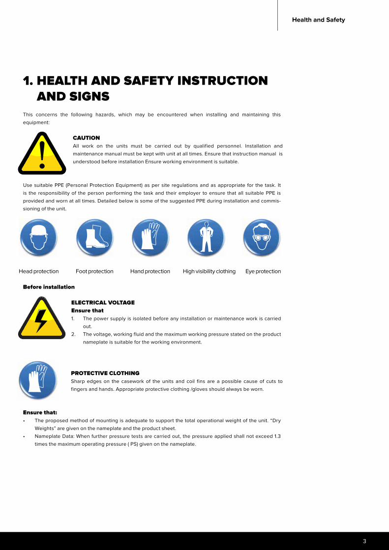
1. HEALTH AND SAFETY INSTRUCTION AND SIGNS This concerns the following hazards, which may be encountered when installing and maintaining this equipment:
Use suitable PPE (Personal Protection Equipment) as per site regulations and as appropriate for the task. It is the responsibility of the person performing the task and their employer to ensure that all suitable PPE is provided and worn at all times. Detailed below is some of the suggested PPE during installation and commis-sioning of the unit.
Before installation
Ensure that:• The proposed method of mounting is adequate to support the total operational weight of the unit. “Dry
Weights” are given on the nameplate and the product sheet.• Nameplate Data: When further pressure tests are carried out, the pressure applied shall not exceed 1.3
times the maximum operating pressure ( PS) given on the nameplate.
CAUTIONAll work on the units must be carried out by qualified personnel. Installation and maintenance manual must be kept with unit at all times. Ensure that instruction manual is understood before installation Ensure working environment is suitable.
Head protection Foot protection Hand protection High visibility clothing Eye protection
ELECTRICAL VOLTAGEEnsure that1. The power supply is isolated before any installation or maintenance work is carried
out.2. The voltage, working fluid and the maximum working pressure stated on the product
nameplate is suitable for the working environment.
PROTECTIVE CLOTHINGSharp edges on the casework of the units and coil fins are a possible cause of cuts to fingers and hands. Appropriate protective clothing /gloves should always be worn.
Health and Safety

Searle Air cooled Condenser , Dry Cooler and Gas cooler
• When ancillary pressure equipment, such as a receiver, is supplied on a frame with a unit, but not a pipe to it, the parts must be treated as separate components and data taken from individual nameplates.
• Rotating blades – dangling items of clothing, jewellery or any items that could be pulled into the fan set are a hazard . Keep safe working distance from the fan plate
• The fan guard should not be removed nor should the fan set be removed from the unit.• During installation and maintenance, ensure that:• The unit is installed and maintained by qualified personnel only. • When pressure testing is carried out, the pressure applied shall not exceed 1.3 times the maximum
operating pressure given on the nameplate of the unit. • The temperature of coils with vinyl-coated fins does not exceed 150°C (e.g. during brazing), as toxic fumes
would be produced.
Be aware of burn hazard:
2. WARRANTY PROCEDUREThis warranty applies to all units detailed in this price list and, unless otherwise stated in product literature or specific contracts, provides for a manufacturer’s guarantee of twenty four months from date of dispatch against faults in workmanship or materials.
When submitting a warranty claim the following information is required:• Customer’s original reference number job / order number.• Kelvion ’s job number / advice note number.• Type of unit and serial number.• Date of installation.• Details of defect.
When providing details of the defect, please give as much information as possible, Was the unit satisfactory on delivery?Frequency of fault (continuous / intermittent)Is the unit leaking ? (+ location of leak)
Items manufactured by Kelvion:No work should be undertaken to resolve the problem either by the customer or a 3rd party until approved by Kelvion - failure to do so could invalidate the warranty.
The item may be replaced or rectified if the guarantee claim is valid.For items that have been installed, Kelvion have the right to decide if rectification on site is suitable and who should undertake the work or whether to return / replace the unit(s). For items where Kelvion decides to replace, the original faulty item must be returned. All items which are returned will be inspected. If the guaran-tee claim is not valid the customer will be advised and further instructions requested, either to return the item or to issue an official order to replace or rectify the item. If you require a replacement product the buyer will be asked to supply a purchase order, when the unit has been returned and evaluated, the buyer will be notified by Searle if the claim is valid.
Items NOT manufactured by Kelvion:• The item will be replaced and the customer will be invoiced• The item will be returned to the supplier for evaluation.• If the claim is valid the credit received from the supplier will be passed on to the customer.
Burn hazards 1. Burn hazards from pipes and pipeline components when the heat exchanger temperature
exceeds 60°C.2. Burn caused by refrigerant coming into contact with the skin or eyes.

5
3. LABELLING ON UNITS
8
1411
8
14
10
117
7
6
6
12
12
14
99
2 21
14
3
5
3
5
2222
3 35
4
5
4 4
1
7
7
6
6
9
14
13
8141112
67
814
910
12
1
Labelling
Searle Air cooled Condenser , Dry Cooler and Gas cooler
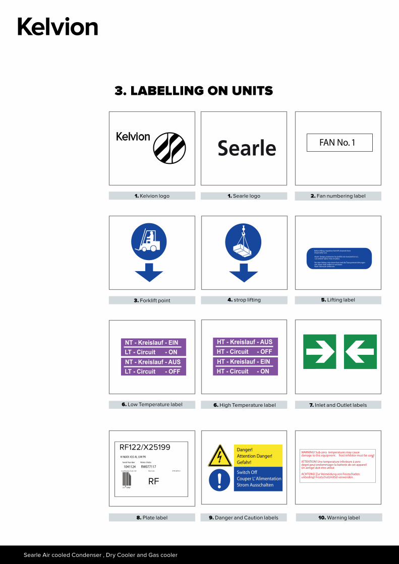
3. LABELLING ON UNITS
1. Searle logo 2. Fan numbering label
3. Forklift point 4. strop lifting 5. Lifting label
6. Low Temperature label 6. High Temperature label 7. Inlet and Outlet labels
8. Plate label
RF122/X25199
RF
9. Danger and Caution labels 10. Warning label
1. Kelvion logo
Kelvion
7
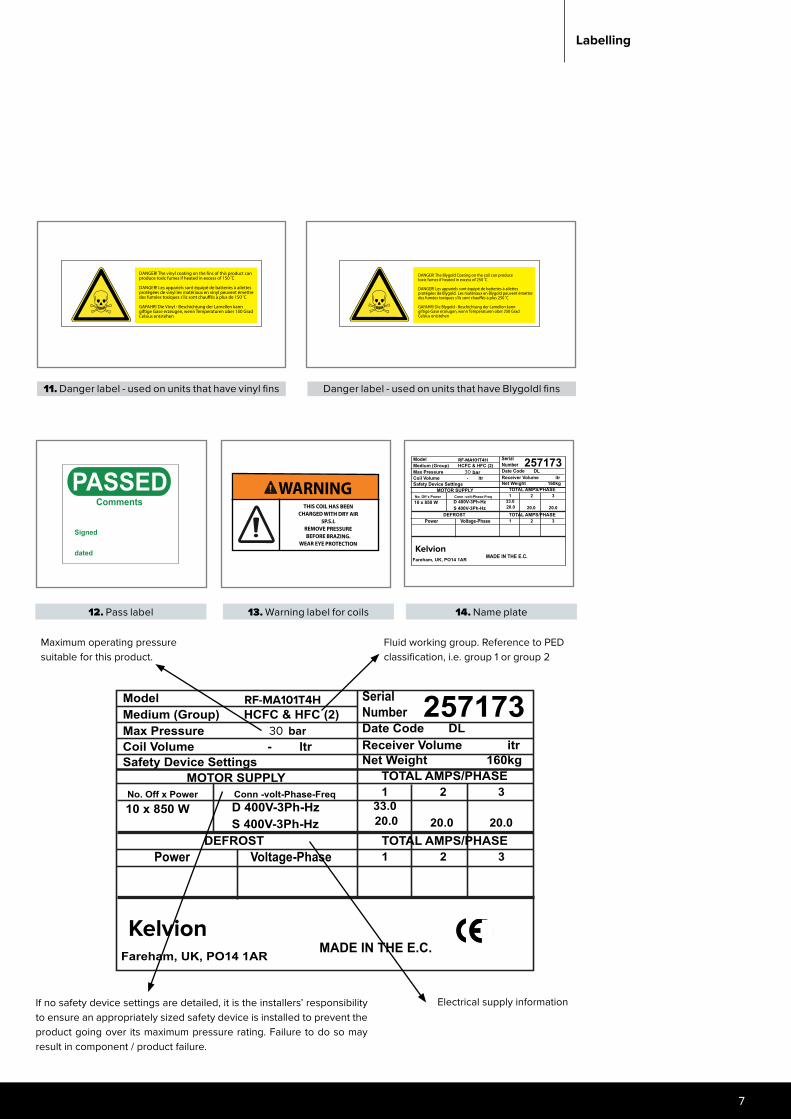
12. Pass label 13. Warning label for coils 14. Name plate
Labelling
Kelvion
RF-MA101T4H
Maximum operating pressure suitable for this product.
Fluid working group. Reference to PED classification, i.e. group 1 or group 2
If no safety device settings are detailed, it is the installers’ responsibility to ensure an appropriately sized safety device is installed to prevent the product going over its maximum pressure rating. Failure to do so may result in component / product failure.
Electrical supply information
bar30
Kelvion
RF-MA101T4H
11. Danger label - used on units that have vinyl fins Danger label - used on units that have Blygoldl fins
bar30
Searle Air cooled Condenser , Dry Cooler and Gas cooler
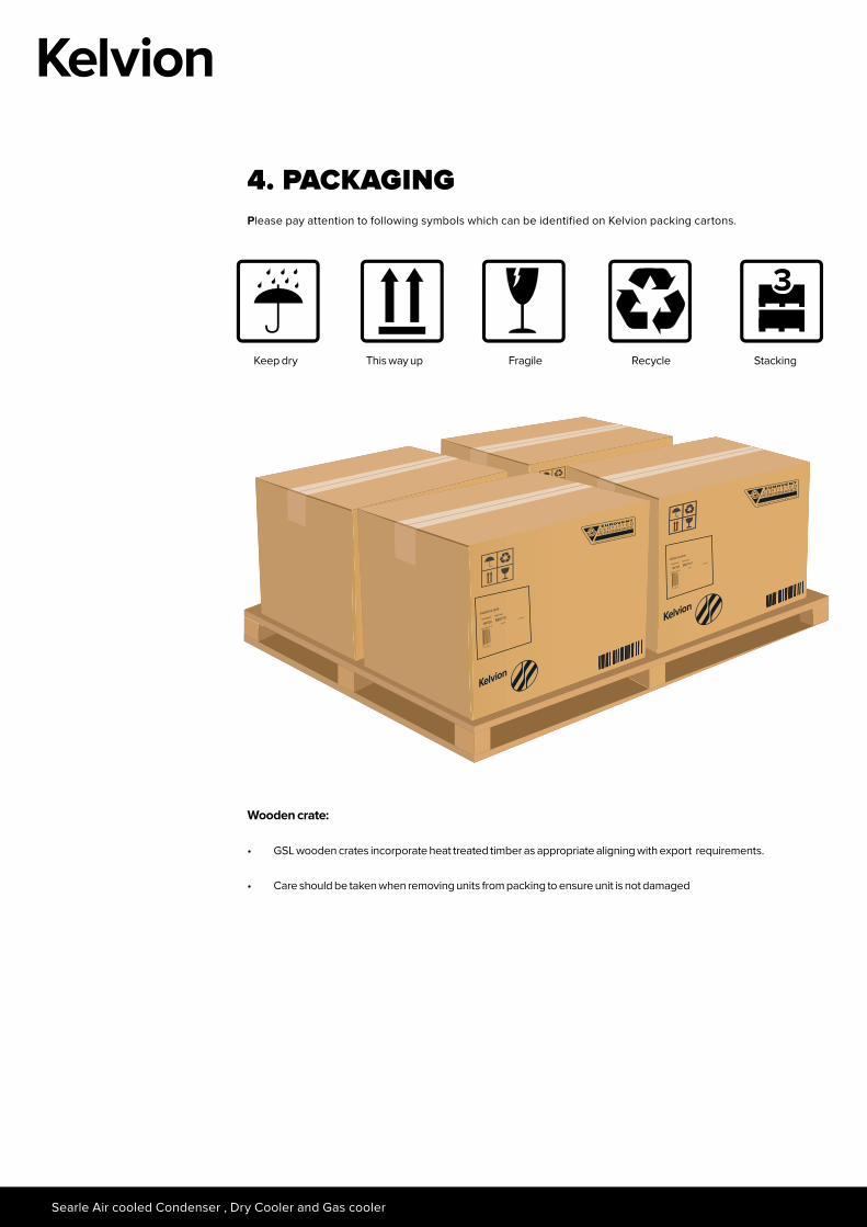
4. PACKAGING Please pay attention to following symbols which can be identified on Kelvion packing cartons.
Wooden crate:
• GSL wooden crates incorporate heat treated timber as appropriate aligning with export requirements.
• Care should be taken when removing units from packing to ensure unit is not damaged
Keep dry This way up Fragile Recycle Stacking
3
9
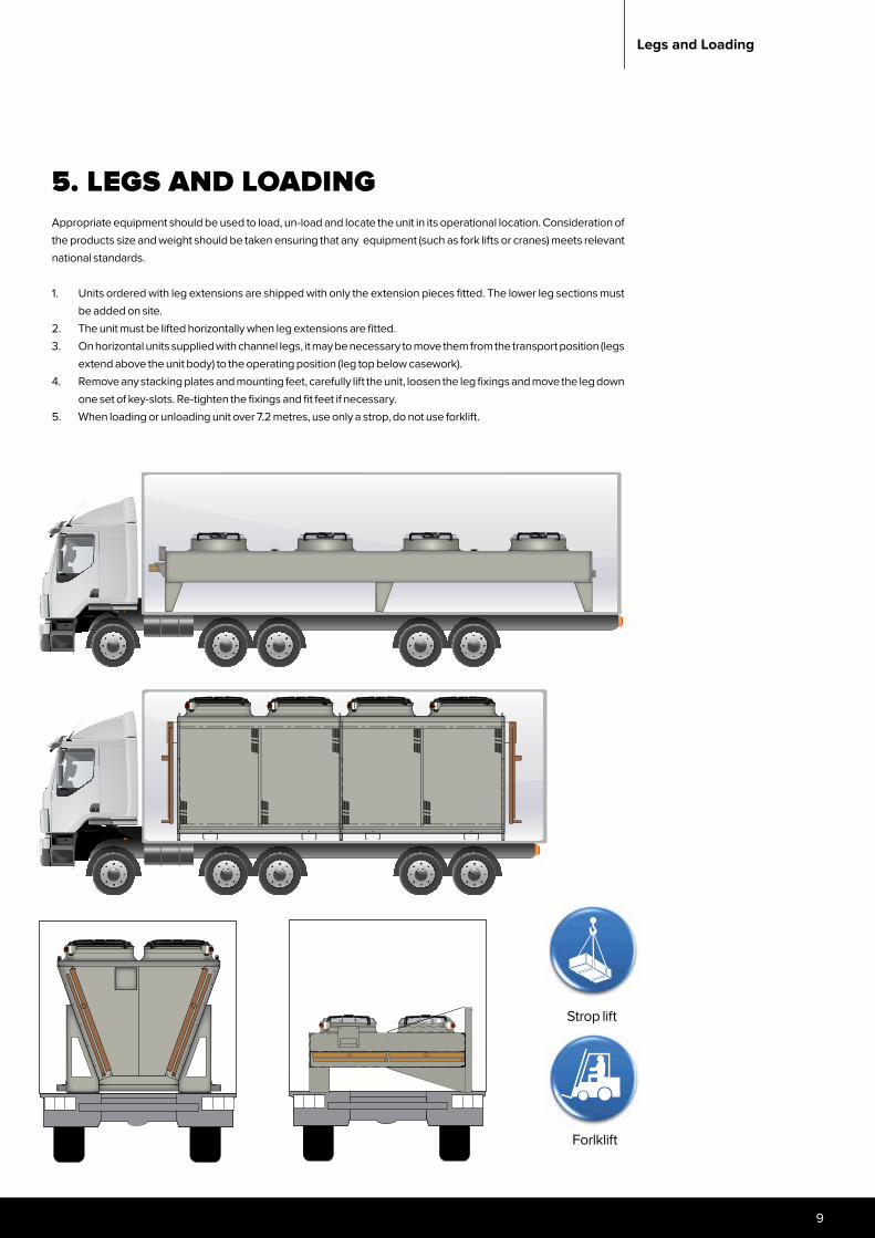
5. LEGS AND LOADINGAppropriate equipment should be used to load, un-load and locate the unit in its operational location. Consideration of the products size and weight should be taken ensuring that any equipment (such as fork lifts or cranes) meets relevant national standards.
1. Units ordered with leg extensions are shipped with only the extension pieces fitted. The lower leg sections must be added on site.
2. The unit must be lifted horizontally when leg extensions are fitted.3. On horizontal units supplied with channel legs, it may be necessary to move them from the transport position (legs
extend above the unit body) to the operating position (leg top below casework).4. Remove any stacking plates and mounting feet, carefully lift the unit, loosen the leg fixings and move the leg down
one set of key-slots. Re-tighten the fixings and fit feet if necessary.5. When loading or unloading unit over 7.2 metres, use only a strop, do not use forklift.
Strop lift
Forlklift
Legs and Loading
Searle Air cooled Condenser , Dry Cooler and Gas cooler
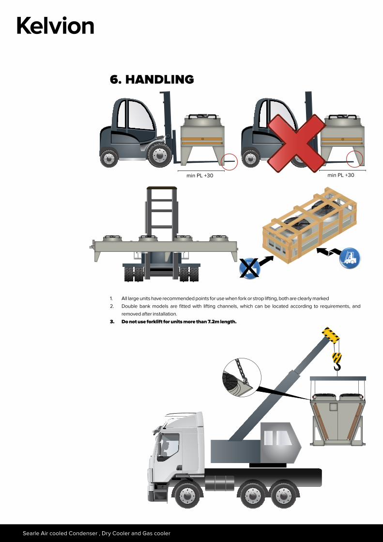
6. HANDLING
1. All large units have recommended points for use when fork or strop lifting, both are clearly marked2. Double bank models are fitted with lifting channels, which can be located according to requirements, and
removed after installation.3. Do not use forklift for units more than 7.2m length.
min PL +30 min PL +30
11
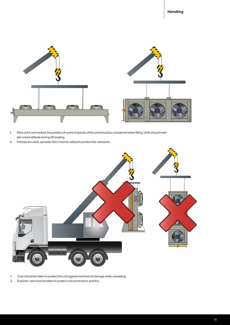
1. If the unit is not marked, the position of centre of gravity of the unit should be considered when lifting. Units should main-tain a level attitude during off-loading.
2. If strops are used, spreader bars must be utilised to protect the casework.
1. Care should be taken to protect the unit against mechanical damage while unloading.2. Extreme care must be taken to protect coil connections and fins.
Handling

Searle Air cooled Condenser , Dry Cooler and Gas cooler
6. HANDLING RF-SJ AND LF-SJ
Forlklift
min PL +30 min PL +30
13
Handling
Searle Air cooled Condenser , Dry Cooler and Gas cooler
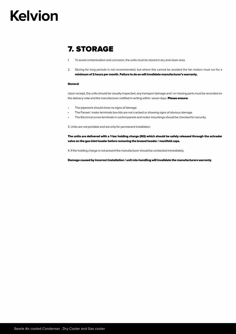
7. STORAGE1. To avoid contamination and corrosion, the units must be stored in dry and clean area.
2. Storing for long periods is not recommended, but where this cannot be avoided the fan motors must run for a minimum of 2 hours per month. Failure to do so will invalidate manufacturer’s warranty.
General
Upon receipt, the units should be visually inspected, any transport damage and / or missing parts must be recorded on the delivery note and the manufacturer notified in writing within seven days. Please ensure:
• The pipework should show no signs of damage• The Fanset / motor terminals box lids are not cracked or showing signs of obvious damage• The Electrical screw terminals in control panels and motor mountings should be checked for security.
3. Units are not portable and are only for permanent installation.
The units are delivered with a 1 bar holding charge (N2) which should be safely released through the schrader valve on the gas inlet header before removing the brazed header / manifold caps.
4. If the holding charge is not present the manufacturer should be contacted immediately.
Damage caused by incorrect installation / unit mis-handling will invalidate the manufacturers warranty
15
8. INSTALLATION AND LOCATION GUIDANCE Before locating the unit in its final location, appropriate load calculations should be completed, taking into consideration functional unit load. This is to ensure its operating platform will withstand the units distributed weight. It is the responsibility of the installer to ensure that the relevant national building legislations are met and the operating surface is suitable to withstand the supplied condenser.
For efficient operation, the unit needs airflow to be unrestricted and inlet air to be at ambient temperature. Units should be fixed securely via the feet / legs supplied. It is the responsibility to of the installer to ensure the unit is fixed in location.
Adjacent building styles, plant and prevailing winds can often cause air currents which, in turn can create down draughts, consequently forcing the discharge air back down into the air intake stream causing high air entering temperatures and subsequent loss of performance. Other adjacent plant, either requiring an air supply or dissipating air will affect the air flow onto the unit. To achieve unrestricted air at ambient temperature, it is necessary to avoid hazards such as:
• Local wind conditions causing warm outlet air to be mixed with the cool inlet.• Inlet air entraining warm exhaust air from other equipment.• Solar heat absorption from surrounding surfaces increasing the local ambient.• Vertical coils should be shaded from the sun.
Adding effects together, it is not unusual for there to be a 5 K temperature increase in inlet air temperature over and above ambient. This obviously has a serious effect on the performance. Sound pressure levels away from the unit will be affected by its surrounding objects/obstructions such as solid walls resulting in higher than specified levels of sound pressure.
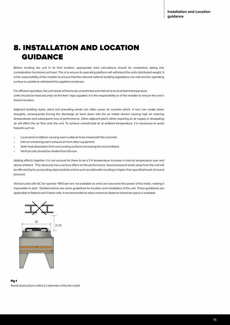
Vertical units with AC fan speeds <400 rpm are not available as wind can overcome the power of the motor, making it impossible to start. Detailed below are some guidelines for location and installation of the unit. These guidelines are applicable to flatbed and V bank units. It recommended to allow maximum distance wherever space is available.
Installation and Location guidance
Fig 1Avoid obstructions within 2 x diameter of the fan outlet
2 x DD
Searle Air cooled Condenser , Dry Cooler and Gas cooler
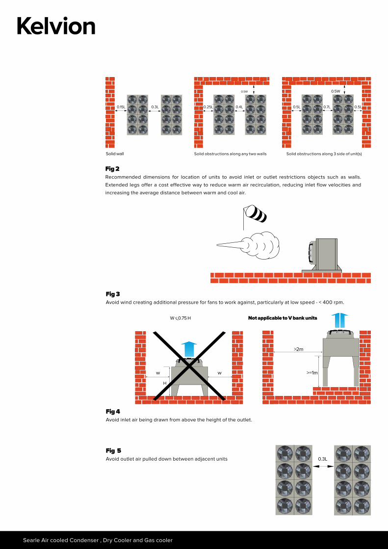
Solid obstructions along 3 side of unit(s)
0.7L0.5L
0.5W
0.5L
Solid wall
0.15L 0.3L
Fig 2Recommended dimensions for location of units to avoid inlet or outlet restrictions objects such as walls. Extended legs offer a cost effective way to reduce warm air recirculation, reducing inlet flow velocities and increasing the average distance between warm and cool air.
Fig 3Avoid wind creating additional pressure for fans to work against, particularly at low speed - < 400 rpm.
W < 0.75 H
>2m
>=1mw w
Not applicable to V bank units
Fig 5Avoid outlet air pulled down between adjacent units
Fig 4Avoid inlet air being drawn from above the height of the outlet.
0.3L
Solid obstructions along any two walls
0.4L0.25L
0.5W
H
17
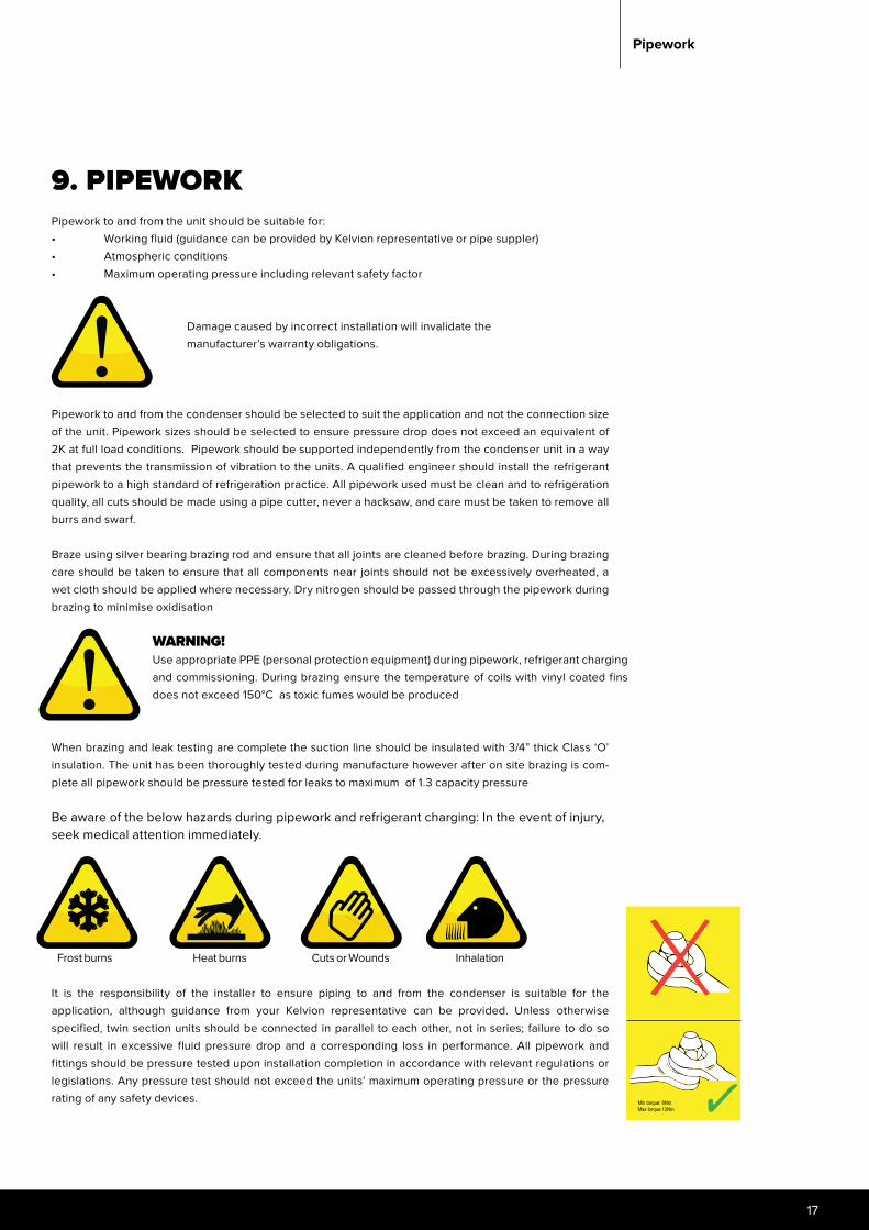
9. PIPEWORK Pipework to and from the unit should be suitable for:• Working fluid (guidance can be provided by Kelvion representative or pipe suppler)• Atmospheric conditions• Maximum operating pressure including relevant safety factor
Damage caused by incorrect installation will invalidate the manufacturer’s warranty obligations.
Pipework to and from the condenser should be selected to suit the application and not the connection size of the unit. Pipework sizes should be selected to ensure pressure drop does not exceed an equivalent of 2K at full load conditions. Pipework should be supported independently from the condenser unit in a way that prevents the transmission of vibration to the units. A qualified engineer should install the refrigerant pipework to a high standard of refrigeration practice. All pipework used must be clean and to refrigeration quality, all cuts should be made using a pipe cutter, never a hacksaw, and care must be taken to remove all burrs and swarf.
Braze using silver bearing brazing rod and ensure that all joints are cleaned before brazing. During brazing care should be taken to ensure that all components near joints should not be excessively overheated, a wet cloth should be applied where necessary. Dry nitrogen should be passed through the pipework during brazing to minimise oxidisation
When brazing and leak testing are complete the suction line should be insulated with 3/4” thick Class ‘O’ insulation. The unit has been thoroughly tested during manufacture however after on site brazing is com-plete all pipework should be pressure tested for leaks to maximum of 1.3 capacity pressure
Be aware of the below hazards during pipework and refrigerant charging: In the event of injury, seek medical attention immediately.
It is the responsibility of the installer to ensure piping to and from the condenser is suitable for the application, although guidance from your Kelvion representative can be provided. Unless otherwise specified, twin section units should be connected in parallel to each other, not in series; failure to do so will result in excessive fluid pressure drop and a corresponding loss in performance. All pipework and fittings should be pressure tested upon installation completion in accordance with relevant regulations or legislations. Any pressure test should not exceed the units’ maximum operating pressure or the pressure rating of any safety devices.
Pipework
Fig 3Avoid wind creating additional pressure for fans to work against, particularly at low speed - < 400 rpm.
Fig 4Avoid inlet air being drawn from above the height of the outlet.
WARNING! Use appropriate PPE (personal protection equipment) during pipework, refrigerant charging and commissioning. During brazing ensure the temperature of coils with vinyl coated fins does not exceed 150°C as toxic fumes would be produced
Frost burns Cuts or WoundsHeat burns Inhalation
Min torque: 8Nm Max torque:12Nm
Searle Air cooled Condenser , Dry Cooler and Gas cooler
10. EVACUATION To avoid potential moisture related problems, it is necessary to evacuate the complete system to a minimum of 1 torr (1.33mbar). All parts of the system must be above freezing and ideally higher than +10°c during evacuation.
11. REFRIGERANT SUB-COOLINGFor a system fitted with a liquid receiver to operate correctly, the receiver should be installed between the condensing and the sub-cooling sections. If no receiver is fitted, a liquid trap should be installed between the two sections.
NOTE: Without a liquid receiver, the degree of sub-cooling will vary with the refrigerant charge.
12. REFRIGERANTSThe refrigerant should be selected appropriately for the application and coordinated with any relevant regional or national regulatory requirements. The refrigerant should be specified when selecting the condenser to ensure appropriate materials are used and that circuit loading is optimised for the application (completed within the Kelvion Searle Product Selector).
Only qualified personnel should be involved with any refrigerant handling, inappropriate installation or failure to adhere to commonly accepted refrigeration practices will invalidate unit warranty.
Safety precautions should be taken when working with refrigerant in accordance with the qualified person- nel’s training. Specific information on the composition and relevant safety precautions will be available from the refrigerant supplier. Detailed information about its incorporation within Searle products can be obtained through contacting the product supplier; Kelvion contact details found at the end of the Installation and Maintenance Instructions.
13. FLUID COOLER APPLICATIONS - FLUID• Ensure that the fluid to be used and any additives are compatible with the unit’s construction.• Fluid Cooler units are designed for use in closed systems, where the fluid is re-circulated.• If the unit is to be used in an open system, extra care is required to prevent corrosion.
Fluid inhibitors may be required to prevent corrosion of system components. The fluid supplier should supply compatibility information with their fluid when incorporated with system components, including details of any required inhibitors. It is the responsibility of the installer to ensure the working fluid is compatible with any supplied products and that necessary precautions / preventative measures are taken to avoid product failure.
National legislation should be adhered to in relation to the supply, usage and eventual disposal of any working fluid
14. FLUID COOLER APPLICATIONS – FROST PROTECTIONFluid coolers using water or water-based solutions must be protected by adding anti-freeze in sufficient concentra-tion, as it is not possible to drain the system completely.
Note: The heat transfer properties of a fluid vary with the concentration of additives
19
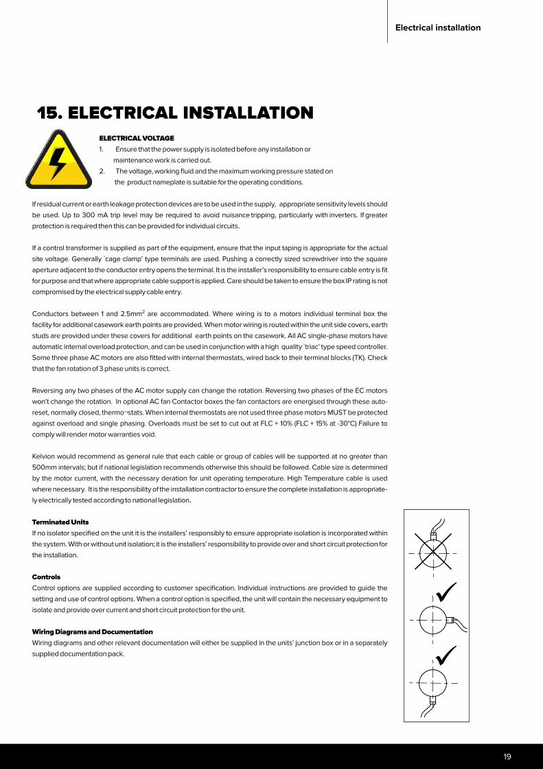
15. ELECTRICAL INSTALLATION
If residual current or earth leakage protection devices are to be used in the supply, appropriate sensitivity levels should be used. Up to 300 mA trip level may be required to avoid nuisance tripping, particularly with inverters. If greater protection is required then this can be provided for individual circuits.
If a control transformer is supplied as part of the equipment, ensure that the input taping is appropriate for the actual site voltage. Generally `cage clamp’ type terminals are used. Pushing a correctly sized screwdriver into the square aperture adjacent to the conductor entry opens the terminal. It is the installer’s responsibility to ensure cable entry is fit for purpose and that where appropriate cable support is applied. Care should be taken to ensure the box IP rating is not compromised by the electrical supply cable entry.
Conductors between 1 and 2.5mm² are accommodated. Where wiring is to a motors individual terminal box the facility for additional casework earth points are provided. When motor wiring is routed within the unit side covers, earth studs are provided under these covers for additional earth points on the casework. All AC single-phase motors have automatic internal overload protection, and can be used in conjunction with a high quality ̀ triac’ type speed controller. Some three phase AC motors are also fitted with internal thermostats, wired back to their terminal blocks (TK). Check that the fan rotation of 3 phase units is correct.
Reversing any two phases of the AC motor supply can change the rotation. Reversing two phases of the EC motors won’t change the rotation. In optional AC fan Contactor boxes the fan contactors are energised through these auto- reset, normally closed, thermo¬stats. When internal thermostats are not used three phase motors MUST be protected against overload and single phasing. Overloads must be set to cut out at FLC + 10% (FLC + 15% at -30°C) Failure to comply will render motor warranties void.
Kelvion would recommend as general rule that each cable or group of cables will be supported at no greater than 500mm intervals; but if national legislation recommends otherwise this should be followed. Cable size is determined by the motor current, with the necessary deration for unit operating temperature. High Temperature cable is used where necessary. It is the responsibility of the installation contractor to ensure the complete installation is appropriate-ly electrically tested according to national legislation.
Terminated Units If no isolator specified on the unit it is the installers’ responsibly to ensure appropriate isolation is incorporated within the system. With or without unit isolation; it is the installers’ responsibility to provide over and short circuit protection for the installation.
ControlsControl options are supplied according to customer specification. Individual instructions are provided to guide the setting and use of control options. When a control option is specified, the unit will contain the necessary equipment to isolate and provide over current and short circuit protection for the unit.
Wiring Diagrams and DocumentationWiring diagrams and other relevant documentation will either be supplied in the units’ junction box or in a separately supplied documentation pack.
Electrical installation
ELECTRICAL VOLTAGE1. Ensure that the power supply is isolated before any installation or maintenance work is carried out.2. The voltage, working fluid and the maximum working pressure stated on the product nameplate is suitable for the operating conditions.
Searle Air cooled Condenser , Dry Cooler and Gas cooler
16. CONDENSERS WITH TRIAC OR INVERTER SPEED CONTROL Care should be taken to ensure that external control wiring to units fitted with TRIAC speed control does not transfer electromagnetic interference to the unit. This may require the fitting of a ferrite core or similar suppression components.Phase cut / triac speed control can cause electromagnetic motor noises which can become dominant. This is likely to cause the actual sound pressure level to deviate from the claimed level or cause obtrusive peak fre-quencies within the sound spectrum.
If an inverte r other than supplied by Kelvion, is to be used it must be set for a “Square Law” voltage to frequency relationship without any energy saving function. To prevent the generation of audible noise a switching frequency of up to 15 kHz may be necessary.
• Mounting the inverter remotely from the unit may result in motor damage.• A screened cable length of 5m (max.) is recommended.• Terminations shall be as short as possible to avoid interference.
When using an inverter speed control, unless otherwise specified, it is mandatory to incorporate an all pole sinusoidal filter for external rotor fans. Further details can be obtained through your Kelvion representative. Default controller set points can be programmed at the factory / to customer request. However, it is advisable the installer calibrate control requirements upon commissioning of the equipment.
17. AC FANS All AC fans have the thermal component connected and may be used as part of the control circuit to protect the motor.
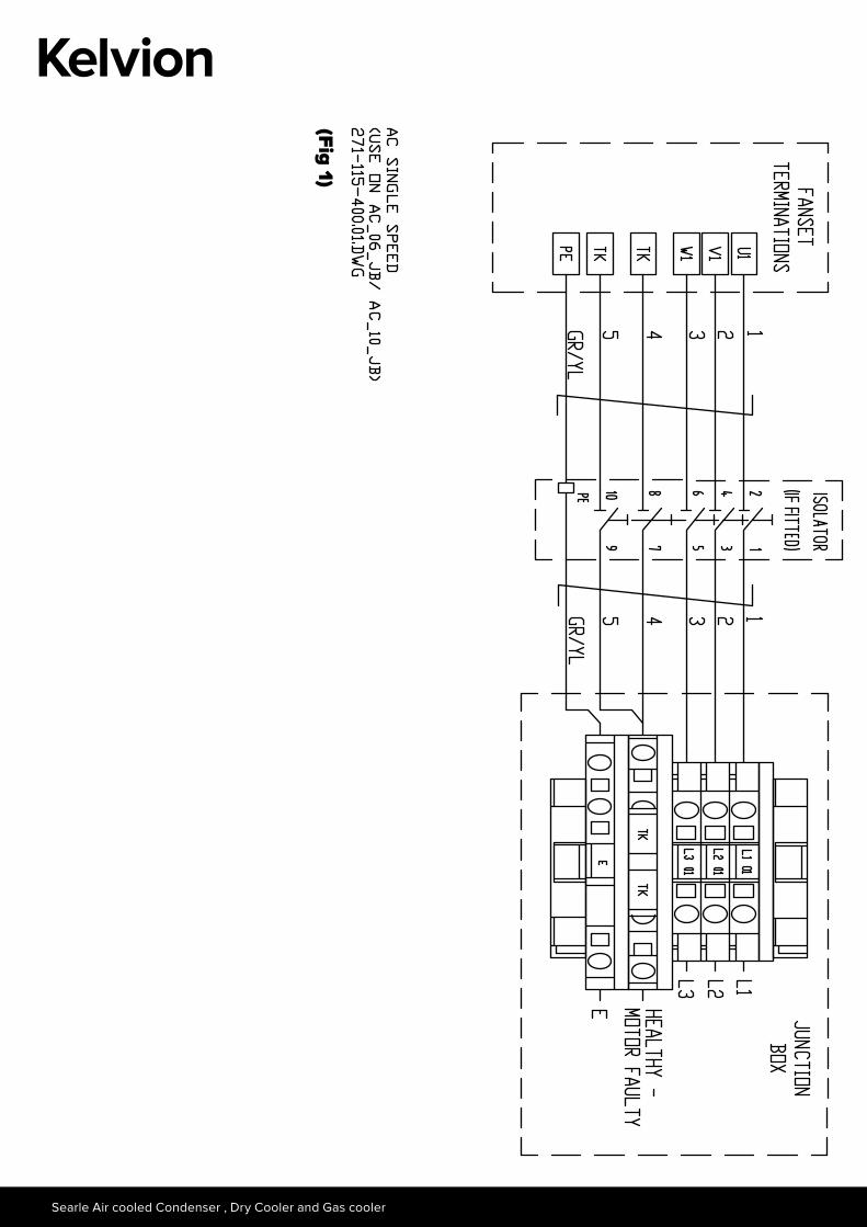
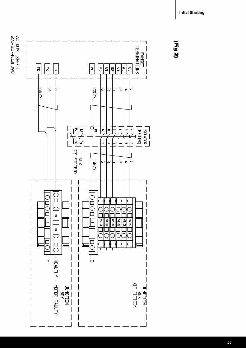
Single SpeedAC fans which can be connected in star or delta depending on application requirements. (Ref. Fig. 1)Dual SpeedOn units suitable for two-speed (Delta/Star) operation speed selection is achieved by using changeover contactors or self-contained dual speed control units.
Note: Changeover contactors MUST be electrically and mechanically interlocked, with a changeover period greater than 50ms. (Ref. Fig. 2)
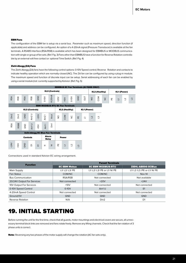
18. EC MOTORSEBM and Ziehl-Abegg (ZA) fans are supplied by a 400Vac or 230Vac, 3-phase or single phase respectively via a MCB. Variable speed control is achieved by using the 0-10Vdc signal (Controller/ Temperature Sensor/Potentiometer). A 10Vdc output signal can be used as a control backup in an event of controller failure (fans run at full speed) is available at the fan terminals.
The status of the fan(s) can be monitored via its healthy contacts providing normally-open (NO) (EBM only) or normally-closed (NC) volt-free function. Kelvion normally connected to the NC terminals, with multiple fans connected in series.
21
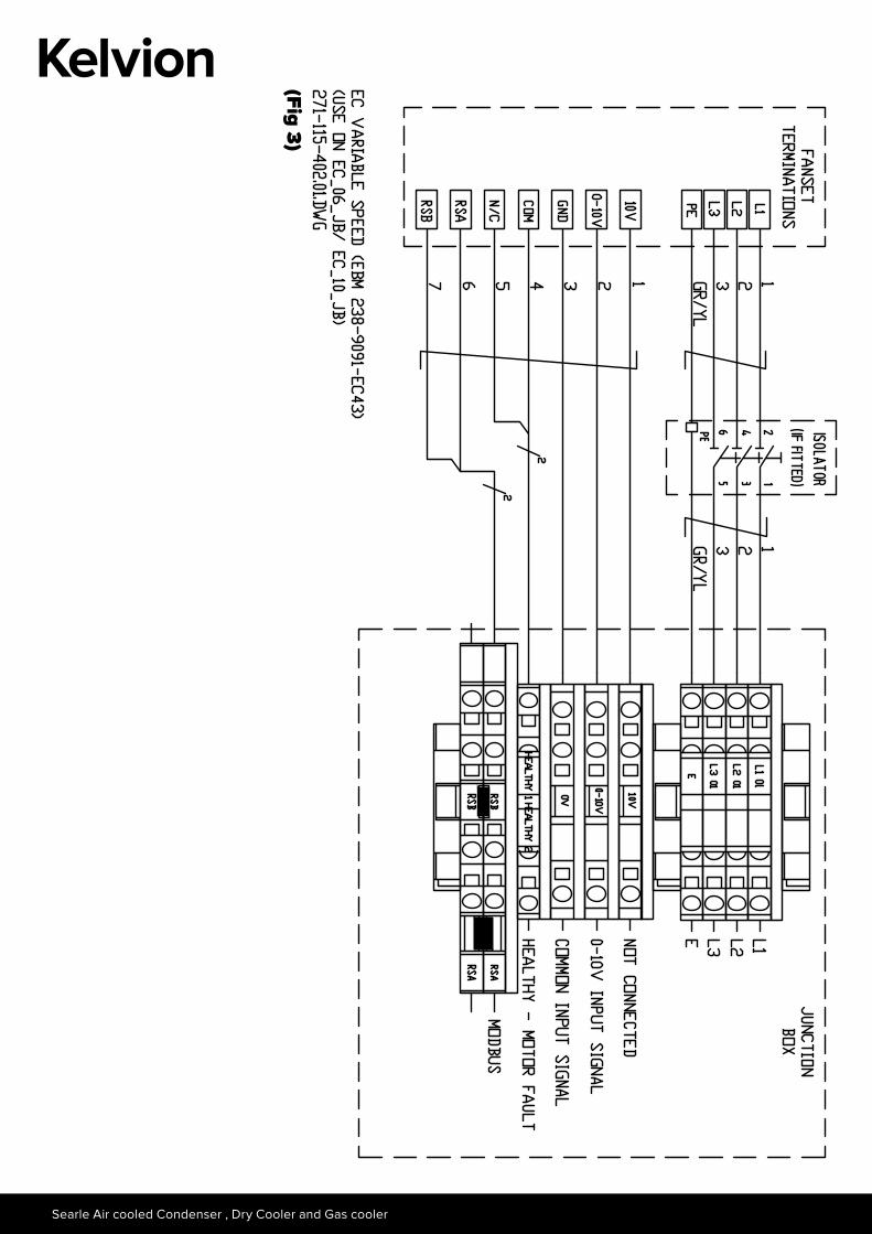
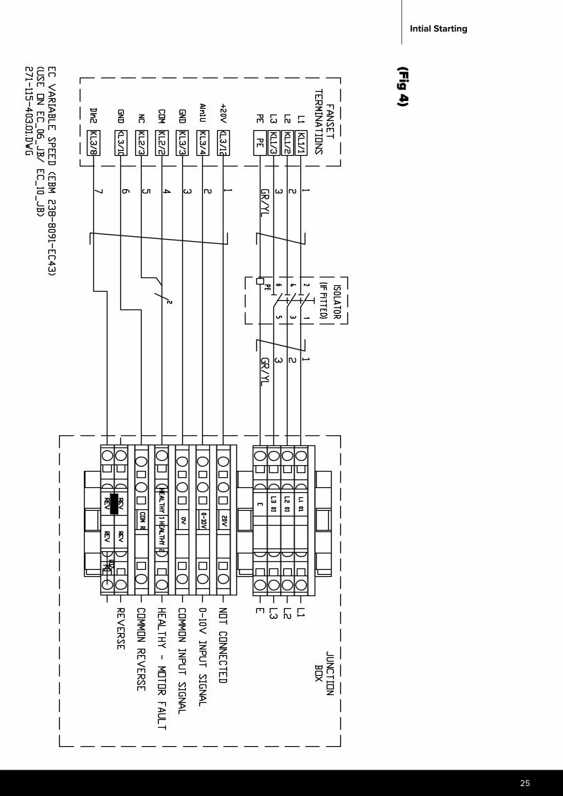
EBM FansThe configuration of the EBM fan is setup via a serial bus. Parameter such as maximum speed, direction function (if applicable) and address can be configured. An option of a 4-20mA signal (Pressure Transducer) is available at the fan terminals. A RS485 Interface (RSA/RSB) is available which has been designed for EBMBUS or MODBUS communica-tion with single or group of fan sets. (Ref. Fig. 3) Fans other than EBMBUS have a function for Reverse Rotation controlla-ble by an external volt free contact or optional Time Switch. (Ref. Fig. 4)
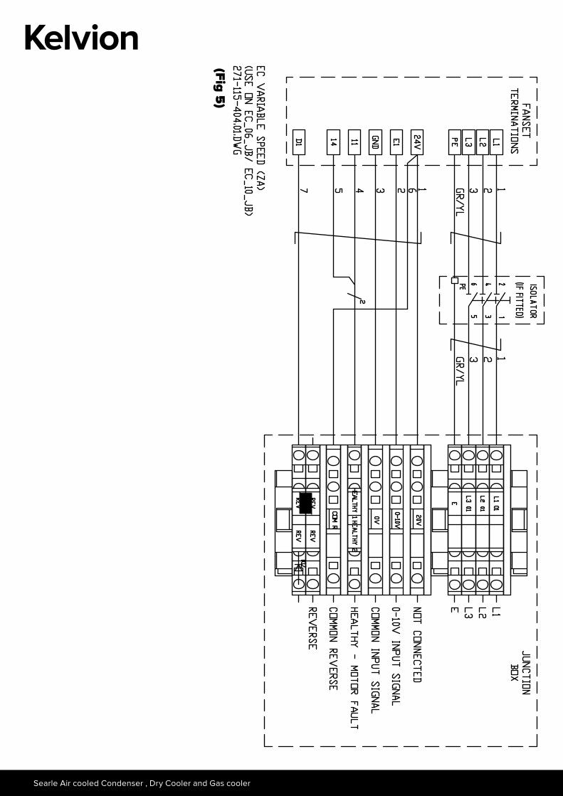
Ziehl-Abegg (ZA) FansThe Ziehl-Abegg (ZA) fans have the following control options: 0-10V Speed control; Reverse Rotation and contacts to indicate healthy operation which are normally-closed (NC). The ZA fan can be configured by using a plug-in module. The maximum speed and function of discrete input can be setup. Serial addressing of each fan can be enabled by using a serial module (not currently supported by Kelvion (Ref. Fig. 5)
EC Motors
EBMBUS EC Fan Terminals (Al FANS ONLY)
RSA
RSA
RSB
RSB
0-1
0V
GN
D
4-20
mA
+10
V
+20
V
0-1
0V
OU
T
GN
D
NO
NC
CO
M
PE
EBM MODBUS RTU EC Fan Terminals
Din
2
GN
D
Din
3
Ain
2 U
Ain
2 I
+20
V
Aou
t
CO
M
NO
NC
L1PE L2 L3
KL3 (Controls) KL2 (Healthy) KL1 (Power)
KL3 (Controls) KL2 (Healthy) KL1 (Power)
RSA
GN
D
RSB
B
Ain
1 U
Ain
1 I
+10
V
Din
1
L1 L2 L3
Controls Alarm Relay
Power
+24V
GN
D
+10
V
D1
E1
Zeihl-Abegg EC Blue Fan Terminals
11 PE14 L1 L2 L3
Connections used in standard Kelvion EC wiring arrangement.
FunctionFanset Terminals
EC EBM Mobus EC EBM MODBUS-RTU ZIEHL-ABEGG ECBlueMain Supply L1/ L2/ L3/ PE L1/ L2/ L3/ PE or L1/ N/ PE L1/ L2 /L3 /PE or L1/ N/ PEFan Status COM/NC COM/NC Nov-14Bus Communication RSA/RSB Not connected Not available20/24V Output For Services Not connected +20V +24V10V Output For Services +10V Not connected Not connected0-10V Speed Control 0-10V Ain1 U E14-20mA Speed Control Not connected Not connected Not connectedGround/0V GND GND GNDReverse Rotation N/A Din2 D1
19. INITIAL STARTING Before running the unit for the first time, check that all guards, motor mountings and electrical covers are secure, all unnec-essary terminal block links are removed and fans rotate freely. Remove any lifting channels. Check that the fan rotation of 3 phase units is correct.
Note: Reversing any two phases of the motor supply will change the rotation (AC fan sets only).
Searle Air cooled Condenser , Dry Cooler and Gas cooler
(Fig 1)
23
Intial Starting
(Fig 2)
Searle Air cooled Condenser , Dry Cooler and Gas cooler
(Fig 3)
25
Intial Starting
(Fig 4)
Searle Air cooled Condenser , Dry Cooler and Gas cooler
(Fig 5)
27
20. MAINTENANCE
Appropriate PPE should be worn when performing maintenance procedures, adhering to specific site requirements as appropriate. Any repairs to the condensers or dry cooler should be undertaken by suitably qualified personal and relevant national regulations should be adhered to, specifically with regards to handling of working fluids and brazing. If any advice or guidance is required with regards to failure or repairs of Searle sup-plied product please contact your local representative. Regular attention should be paid to the system operating requirements to ensure that the operating parameters are within the products/system specifications.
Every month check:• Fan motors must be operated for at least 2 hours every month to prevent possible fan set failure• Coil condition, i.e clogging
Every 12 months check:• Security of fixings especially fan motor mountings. • Refrigerant fluid pipework for damage and leaks.• Motor(s) rotate freely.• Electrical connections for security of attachment. Check all external surfaces annually for any corrosion or
peeling. Clean any affected area thoroughly with a wire brush, apply a coat of zinc primer and retouch with a suitable finishing paint.
When necessary:Clean the fins, guards and general casework. Care must be taken when cleaning the fins to prevent damage. A soft brush and mild detergent solution is recommended.
The following routine annual maintenance is recommended:
• Check security of fixings especially fan motor mountings.• Check refrigerant pipeline for damage and leaks.• Check all motors rotate freely.• Check electrical connections for security of attachment.• Check heat exchanger coil for build upbuild-up of debris or soiling.• Check all external surfaces annually for any corrosion or peeling.- cleaning any affected area thoroughly
with a wire brush before applying a zinc primer to the area and complete with an appropriate finishing paint. • Clean any affected area thoroughly with a wire brush, apply a coat of zinc primer and retouch with a suitable
finishing paint.• On belt drive units, every month check belt tension and wear.• On completion of work ensure all objects are removed from the unit.• Only original spare parts should be used if replacing failed components.
Maintenance
WARNING!
The Unit must be Electrically Isolated before certain Maintenance Work is undertaken.
Searle Air cooled Condenser , Dry Cooler and Gas cooler
Component Replacement
Pressure Transducer/ Pressure switchesWhen removing the pressure devices safety goggles and gloves must be worn.
When starting the necessary maintenance routine please be aware of the following hazards
21. COIL CLEANINGIt is essential that the heat exchanger coil is kept clean to maintain the designed heat transfer rate and help to ensure the units life cycle meets expectations. General debris such as leaves, paper, dust and pollen can be removed using a brush, with compressed air blowing against direction of airflow (Max pressure 3bar) or an industrial vacuum cleaner.
The fin should be brushed in the longitudinal direction of the fins with a soft brush.If using EC fans, it is possible to reverse these using the designated input signal to the fan set (view unit specific wiring diagram). The fans will operate as per the 0 – 10 V input signal. To move as much debris as possible, it is advisable to run the fans at the maximum speed the application noise level will allow. For what this voltage will be, with respect to the unit noise level please contact your local Kelvion representative. The fans do not need to operate in reverse for longer than 2 minutes to move large debris and some lightly applied particles on the fin surface.
Heavier fouling must be removed using a pressure water/steam jet washer (Max pressure 3bar) against direction of airflow, at a distance of 300 to 400mm using a neutral cleaning agent if required. The spray should be even across the coil face and as with a brush, applied in a longitudinal direction across the fins.
The jet of the cleaner should be held vertical to the fin bank to avoid fin damage.Any cleaning fluids should be suitable for use on both tube and fin materials, incorrect use of fluids could be corrosive towards heat exchanger materials. For clarification of specific cleaning fluids, please contact your local Kelvion representative who will be able to provide specific guidance on the acceptability of the working fluid.General Cleaning Steps• Reverse fans daily for up to 2 minutes to remove large debris• Check coil at regular intervals for any large debris which has not been move. Using a soft brush, in the
direction of the fins, gently remove this debris• Approximately every 6 months, from the air off face of the coil, a water jet, possibly with a suitable clean-
ing agent, should be applied to help remove any debris that have progressed inwards of the air on face of the heat exchanger
If there are concerns that debris remain within the coil, or there are signs that the above steps have not fully removed fouling, then please contact Kelvion directly for further guidance.
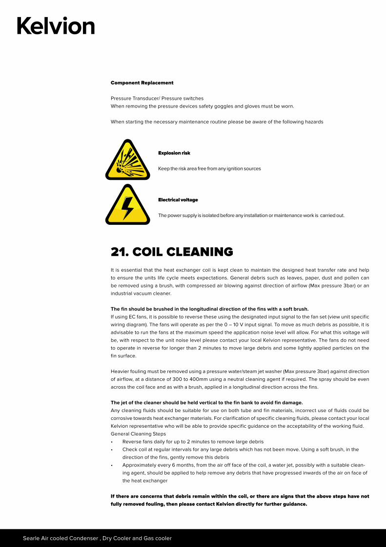
Explosion risk
Keep the risk area free from any ignition sources
Electrical voltage
The power supply is isolated before any installation or maintenance work is carried out.
29
22. STANDARDS• 97/23/EC Pressure Equipment Directive• 2006/42/EC Machinery Directive• En 378; Parts 1 to 4; “Refrigeration systems and heat pumps, technical safety and environmental
requirements”• 2006/95/EC Low Voltage Directive• EN60204-1: 1999 Safety of machinery-Electrical equipment of machines• BS EN 61032: 1998 Protection of persons and equipment by enclosures, Probes for verification
(propeller fan units)• BS EN13857:2008 Safety of machinery- Safety distances to prevent hazard zones being reached by
the upper and lower limbs.
23. INVALIDATION OF GUARANTEEKelvion accepts no liability according to Kelvion’s terms and conditions of sale, or for loss or damage arising as a result of:
1. Failure to install set up or put to work any part of the equipment in the manner specified in the Installation and Maintenance Instructions
2. Failure to maintain the equipment in the manner specified in the Installation and Maintenance Instructions3. Replacement parts, additional parts or accessories manufactured by persons other than Kelvion having been
incorporated into, or attached to the equipment.4. The equipment having been adapted for use, operated or used in such a way as does conform to Kelvion’s
recommendation.
Coil cleaning
Searle Air cooled Condenser , Dry Cooler and Gas cooler
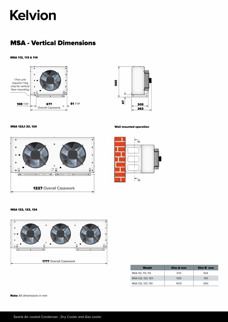
MSA - Vertical Dimensions
MSA 112, 113 & 114
MSA 122,1 23, 124
108 TYP 677 Overall Casework
1 Fan unit requires 1 leg
only for vertical floor mounting
51 TYP
1227 Overall Casework
565
363
47 305
MSA 132, 133, 134
1777 Overall Casework
Wall mounted operation
W
W
Model Dim A mm Dim B mm
MSA 112, 113, 114 570 N/A
MSA 122, 123, 124 1120 100
MSA 132, 133, 134 1670 650
Note: All dimensions in mm
31
MSA Dimensions
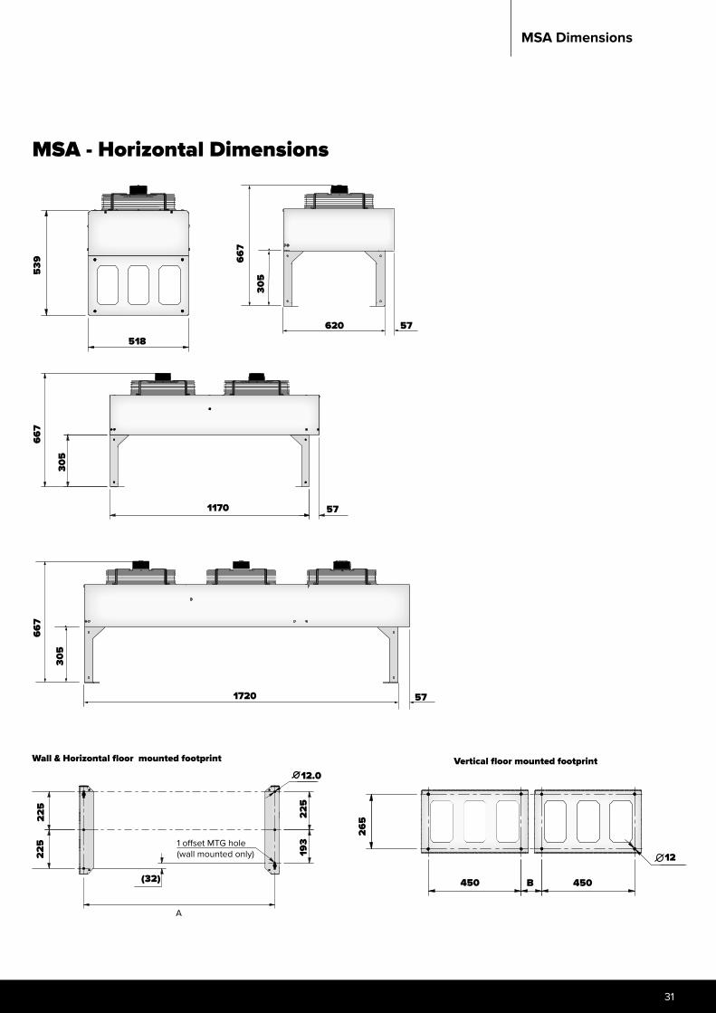
MSA - Horizontal Dimensions
Model Dim A mm Dim B mm
MSA 112, 113, 114 570 N/A
MSA 122, 123, 124 1120 100
MSA 132, 133, 134 1670 650
667
305
1170 57
Wall & Horizontal floor mounted footprint
539
518
225
(32)
225
12.0
225
193
A
1 offset MTG hole(wall mounted only)
Vertical floor mounted footprint
B
12
265
450 450
620 57
305
667
667
305
1720 57

Searle Air cooled Condenser , Dry Cooler and Gas cooler
1002.4195 34.7
972.
3
22.5 957,4 CTRS 22.5
828
Fixing points
48 245 248 245 48
834
4002,4
3957,4 CTRS
972.
3
195 34.7
22.5 22.5
3002,4195 34.7
972.
3
22.5 2957,4 CTRS 22.5
2002.4195 34.7
972.
3
22.5 1957,4 CTRS 22.5
33
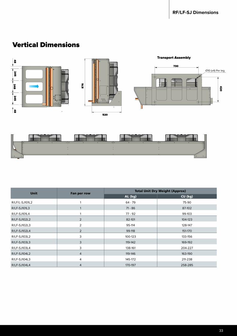
RF/LF-SJ Dimensions
Transport Assembly
876
520
730O10 (x4) Per leg
420
Vertical Dimensions
48245
248245
48
Unit Fan per rowTotal Unit Dry Weight (Approx)
AL (kg) CU (kg)
R/LF/L-SJ101L2 1 64 - 79 75-90
R/LF-SJ101L3 1 71 - 86 87-102
R/LF-SJ101L4 1 77 - 92 99-103
R/LF-SJ102L2 2 82-101 104-123
R/LF-SJ102L3 2 95-114 128-147
R/LF-SJ102L4 2 99-118 151-170
R/LF-SJ103L2 3 100-123 133-156
R/LF-SJ103L3 3 119-142 169-192
R/LF-SJ103L4 3 138-161 204-227
R/LF-SJ104L2 4 119-146 163-190
R/LF-SJ104L3 4 145-172 211-238
R/LF-SJ104L4 4 170-197 258-285

Searle Air cooled Condenser , Dry Cooler and Gas cooler
Unit ModuleFan per banks
Dim A Dim B1 Dim B2 Dim B3
Total Unit Dry Weight (Approx)M* N* P1* P2*
Al Cu Al Cu Al Cu Al Cukg kg kg kg kg kg kg kg
_F_A_01T2 1200 1 1203 1123 214 239 258 294 315 366 365 416_F_A_01T3 1200 1 1203 1123 226 265 276 330 340 416 390 466_F_A_01T4 1200 1 1203 1123 239 290 293 366 365 467 415 517_F_A_02T2 1200 2 2403 2323 369 421 454 526 552 655 649 752_F_A_02T3 1200 2 2403 2323 394 471 489 597 685 756 699 853_F_A_02T4 1200 2 2403 2323 419 522 524 669 652 857 749 954_F_A_03T2 1200 3 3603 3523 525 602 650 758 790 944 934 1088_F_A_03T3 1200 3 3603 3523 562 678 702 865 865 1095 1009 1239_F_A_03T4 1200 3 3603 3523 600 753 755 972 939 1247 1083 1391_F_A_04T2 1200 4 4803 4723 574 676 738 883 921 1126 1112 1316_F_A_04T3 1200 4 4803 4723 624 777 808 1025 1020 1328 1211 1518_F_A_04T4 1200 4 4803 4723 673 878 879 1168 1120 1529 1310 1720_F_A_05T2 1200 5 6003 5923 695 823 900 1081 1124 1381 1362 1618_F_A_05T3 1200 5 6003 5923 758 950 988 1259 1249 1633 1486 1871_F_A_05T4 1200 5 6003 5923 820 1076 1075 1437 1373 1885 1611 2123_F_A_06T2 1200 6 7203 7123 3562 3561 827 971 1061 1278 1328 1635 1613 1920_F_A_06T3 1200 6 7203 7123 3562 3561 891 1122 1167 1492 1477 1938 1762 2223_F_A_06T4 1200 6 7203 7123 3562 3561 966 1273 1272 1706 1626 2241 1911 2525_F_A_07T2 1200 7 8403 8323 3562 4761 969 1149 1254 1507 1562 1921 1895 2254_F_A_07T3 1200 7 8403 8323 3562 4761 1056 1325 1376 1756 1736 2274 2069 2607_F_A_07T4 1200 7 8403 8323 3562 4761 1143 1502 1499 2005 1910 2627 2243 2960_F_A_08T2 1200 8 9603 9523 4762 4761 1091 1296 1415 1705 1766 2176 2146 2555_F_A_08T3 1200 8 9603 9523 4762 4761 1190 1497 1555 1989 1964 2579 2344 2959_F_A_08T4 1200 8 9603 9523 4762 4761 1289 1699 1696 2274 2163 2982 2543 3362_F_A_09T2 1200 9 10803 10723 4762 5961 1212 1443 1577 1902 1969 2430 2396 2857_F_A_09T3 1200 9 10803 10723 4762 5961 1324 1670 1734 2223 2193 2884 2619 3311_F_A_09T4 1200 9 10803 10723 4762 5961 1436 1897 1892 2543 2416 3338 2843 3765_F_A_10T2 1200 10 12003 11923 5962 5961 1334 1590 1738 2100 2173 2685 2646 3159_F_A_10T3 1200 10 12003 11923 5962 5961 1458 1842 1913 2456 2421 3189 2895 3663_F_A_10T4 1200 10 12003 11923 5962 5961 1582 2094 2089 2812 2669 3694 3143 4167
_F_B_01T2 1500 1 1503 1423 233 265 281 327 353 417 405 469_F_B_01T3 1500 1 1503 1423 248 296 303 371 384 480 436 532_F_B_01T4 1500 1 1503 1423 264 328 326 416 415 543 467 595_F_B_02T2 1500 2 3003 2923 408 472 500 591 629 757 729 857_F_B_02T3 1500 2 3003 2923 439 535 544 680 691 883 791 983_F_B_02T4 1500 2 3003 2923 470 598 588 769 753 1009 853 1110_F_B_03T2 1500 3 4503 4423 454 550 591 727 776 968 925 1117_F_B_03T3 1500 3 4503 4423 501 645 657 861 870 1158 1019 1307_F_B_03T4 1500 3 4503 4423 547 740 723 994 963 1347 1112 1496_F_B_04T2 1500 4 6003 5923 616 744 797 978 1039 1295 1237 1493_F_B_04T3 1500 4 6003 5923 678 870 885 1156 1163 1548 1361 1745_F_B_04T4 1500 4 6003 5923 740 997 973 1334 1288 1800 1485 1998_F_B_05T2 1500 5 7503 7423 2962 4461 748 908 974 1200 1272 1592 1519 1839_F_B_05T3 1500 5 7503 7423 2962 4461 826 1066 1083 1422 1428 1908 1674 2154_F_B_05T4 1500 5 7503 7423 2962 4461 903 1224 1193 1645 1583 2223 1829 2469_F_B_06T2 1500 6 9003 8923 4462 4461 880 1073 1150 1421 1505 1890 1800 2185_F_B_06T3 1500 6 9003 8923 4462 4461 913 1262 1282 1688 1692 2268 1987 2563_F_B_06T4 1500 6 9003 8923 4462 4461 1066 1451 1413 1956 1878 2646 2173 2941_F_B_07T2 1500 7 10503 10423 4462 5961 1043 1267 1357 1674 1769 2218 2114 2562_F_B_07T3 1500 7 10503 10423 4462 5961 1152 1488 15111 1985 1987 2659 2331 3004_F_B_07T4 1500 7 10503 10423 4462 5961 1260 1709 1664 2297 2204 3100 2549 3445_F_B_08T2 1500 8 12003 11923 5962 5961 1175 1431 1534 1895 2002 2515 2396 2908_F_B_08T3 1500 8 12003 11923 5962 5961 1299 1684 1709 2251 2251 3019 2664 3413_F_B_08T4 1500 8 12003 11923 5962 5961 1423 1936 1884 2607 2499 3524 3413 3917
_F_C_01T2 1800 1 1803 1723 252 290 305 359 357 433 410 487_F_C_01T3 1800 1 1803 1723 271 328 331 413 394 509 447 562_F_C_01T4 1800 1 1803 1723 289 366 358 466 431 585 485 638_F_C_02T2 1800 2 3603 3523 446 523 547 656 636 790 740 893_F_C_02T3 1800 2 3603 3523 483 599 600 763 711 941 814 1045_F_C_02T4 1800 2 3603 3523 521 674 652 869 785 1093 889 1196_F_C_03T2 1800 3 5403 5323 486 601 636 798 762 992 916 1146_F_C_03T3 1800 3 5403 5323 542 715 715 959 874 1219 1027 1373_F_C_03T4 1800 3 5403 5323 598 828 794 1119 985 1446 1139 1600_F_C_04T2 1800 4 7203 7123 3562 3561 659 812 857 1074 1020 1327 1224 1531_F_C_04T3 1800 4 7203 7123 3562 3561 733 964 962 1287 1169 1630 1373 1834_F_C_04T4 1800 4 7203 7123 3562 3561 807 1115 1067 1501 1318 1933 1522 2137_F_C_05T2 1800 5 9003 8923 3562 5361 801 993 1048 1319 1248 1633 1502 1887_F_C_05T3 1800 5 9003 8923 3562 5361 894 1182 1179 1586 1435 2011 1689 2265_F_C_05T4 1800 5 9003 8923 3562 5361 987 1372 1311 1853 1621 2389 1875 2643_F_C_06T2 1800 6 10803 10723 5362 5361 974 1204 1269 1594 1507 1968 1811 2272_F_C_06T3 1800 6 10803 10723 5362 5361 1085 1431 1426 1915 1730 2421 2034 2726_F_C_06T4 1800 6 10803 10723 5362 5361 1197 1658 1584 2235 1953 2875 2258 3180
_F_D_01T2 2100 1 2103 2023 271 316 328 454 395 484 450 539_F_D_01T3 2100 1 2103 2023 293 360 359 454 438 573 493 628_F_D_01T4 2100 1 2103 2023 404 404 390 516 482 661 537 716_F_D_02T2 2100 2 4203 4123 365 454 474 601 593 772 699 879_F_D_02T3 2100 2 4203 4123 408 542 536 725 350 949 786 1055_F_D_02T4 2100 2 4203 4123 631 631 597 850 767 1125 873 1232_F_D_03T2 2100 3 6303 6223 577 712 740 930 910 1179 1069 1338_F_D_03T3 2100 3 6303 6223 643 844 832 1117 1041 1444 1199 1602_F_D_03T4 2100 3 6303 6223 977 977 924 10304 1171 1709 1330 1861_F_D_04T2 2100 4 8403 8323 4162 4161 731 910 946 1199 1168 1527 1378 1737_F_D_04T3 2100 4 8403 8323 4162 4161 818 1087 1068 1448 1342 1880 1552 2090_F_D_04T4 2100 4 8403 8323 4162 4161 1263 1263 1191 1697 1516 2233 1726 2443_F_D_05T2 2100 5 10503 10423 4162 6261 884 1108 1152 1468 1426 1874 1688 2136_F_D_05T4 2100 5 10503 10423 4162 6261 993 1329 1305 1780 1643 2316 1905 2578_F_D_05T3 2100 5 10503 10423 4162 6261 1549 1549 458 2091 1861 2757 2122 3019
RF/LF/NF/GF Dimensions
Note: M*, N*, P1* = 1 bank of fans. P2* = 2 banks of fans.
35
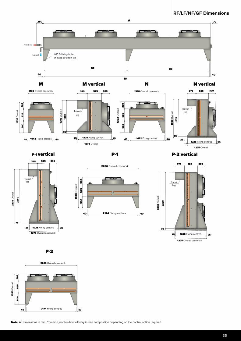
RF/LF/NF/GF Dimensions
B1
B2
40
Ø15.0 fixing holein base of each leg
A
B3
40
70
Hot gas
Liquid
250
M M vertical N N vertical
RF-P2
1578 Overall casework
1333
Ove
rall
1492 Fixing centres
500
525
309
40 40
1205
Ove
rall
2525
375 309525
1225 Fixing centres
1275 Overall
Transit leg
1653
Ove
rall
2525
375 309525
1225 Fixing centres
1275 Overall
Transit leg
75
1578
75
1130
40
1130 Overall casework
500
525
309
1333
Ove
rall
1044 Fixing centres 40
2335
Ove
rall
P-1 vertical375 309525
Transit leg
2525
2260
1225 Fixing centres
1275 Overall casework
75
2174 Fixing centres
2260 Overall casework
1333
Ove
rall
500
525
309
40 40
P-1
375 309525
2525
2260
2335
Ove
rall
1225 Fixing centres
1275 Overall casework
P-2 vertical
75
Transit leg
P-2
1333
Ove
rall
2260 Overall casework
2174 Fixing centres
500
525
309
40 40
Note: All dimensions in mm. Common junction box will vary in size and position depending on the control option required.
Searle Air cooled Condenser , Dry Cooler and Gas cooler
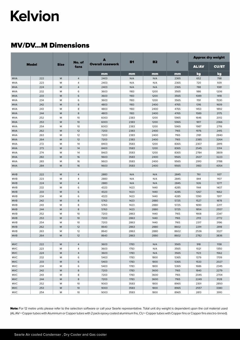
Model Size No. of fans
AOverall casework B1 B2 C
Approx dry weight
AL/AV CU/ET
mm mm mm mm kg kgMVA 222 M 4 2403 N/A N/A 2365 652 798
MVA 223 M 4 2403 N/A N/A 2365 720 939
MVA 224 M 4 2403 N/A N/A 2365 788 1081
MVA 232 M 6 3603 1183 1200 3565 986 1206
MVA 233 M 6 3603 1183 1200 3565 1089 1418
MVA 234 M 6 3603 1183 1200 3565 1191 1530
MVA 242 M 8 4803 1183 2400 4765 1316 1609
MVA 243 M 8 4803 1183 2400 4765 1453 1892
MVA 244 M 8 4803 1183 2400 4765 1589 2175
MVA 252 M 10 6003 2383 1200 5965 1646 2012
MVA 253 M 10 6003 2383 1200 5965 1817 2366
MVA 254 M 10 6003 2383 1200 5965 1987 2719
MVA 262 M 12 7203 2383 2400 7165 1976 2415
MVA 263 M 12 7203 2383 2400 7165 2181 2840
MVA 264 M 12 7203 2383 2400 7165 2385 3264
MVA 272 M 14 8403 3583 1200 8365 2307 2819
MVA 273 M 14 8403 3583 1200 8365 2545 3314
MVA 274 M 14 8403 3583 1200 8365 2784 3809
MVA 282 M 16 9603 3583 2400 9565 2637 3223
MVA 283 M 16 9603 3583 2400 9565 2910 3788
MVA 284 M 16 9603 3583 2400 9565 3183 4354
MVB 222 M 4 2883 N/A N/A 2845 761 937
MVB 223 M 4 2883 N/A N/A 2845 844 1107
MVB 224 M 4 2883 N/A N/A 2845 926 1277
MVB 232 M 6 4323 1423 1440 4285 1144 1407
MVB 233 M 6 4323 1423 1440 4285 1267 1662
MVB 234 M 6 4323 1423 1440 4285 1390 1917
MVB 242 M 8 5763 1423 2880 5725 1527 1878
MVB 243 M 8 5763 1423 2880 5725 1690 2217
MVB 244 M 8 5763 1423 2880 5725 1854 2557
MVB 252 M 10 7203 2863 1440 7165 1908 2347
MVB 253 M 10 7203 2863 1440 7165 2113 2772
MVB 254 M 10 7203 2863 1440 7165 2317 3196
MVB 262 M 12 8643 2863 2880 8602 2291 2818
MVB 263 M 12 8643 2863 2880 8602 2536 3327
MVB 264 M 12 8643 2863 2880 8602 2782 3836
MVC 222 M 4 3603 1783 N/A 3565 918 1138
MVC 223 M 4 3603 1783 N/A 3565 1021 1350
MVC 224 M 4 3603 1783 N/A 3565 1123 1562
MVC 232 M 6 5403 1783 1800 5365 1379 1709
MVC 233 M 6 5403 1783 1800 5365 1533 2027
MVC 234 M 6 5403 1783 1800 5365 1686 2345
MVC 242 M 8 7203 1783 3600 7165 1840 2279
MVC 243 M 8 7203 1783 3600 7165 2045 2704
MVC 244 M 8 7203 1783 3600 7165 2249 3128
MVC 252 M 10 9003 3583 1800 8965 2301 2850
MVC 253 M 10 9003 3583 1800 8965 2557 3380
MVC 254 M 10 9003 3583 1800 8965 2813 3910
MV/DV...M Dimensions
Note: For 12 metre units please refer to the selection software or call your Searle representative. Total unit dry weight is dependent upon the coil material used (AL/AV = Copper tubes with Aluminium or Copper tubes with 2 pack epoxy coated aluminium fns, CU = Copper tubes with Copper fins or Copper fins electro-tinned).
37
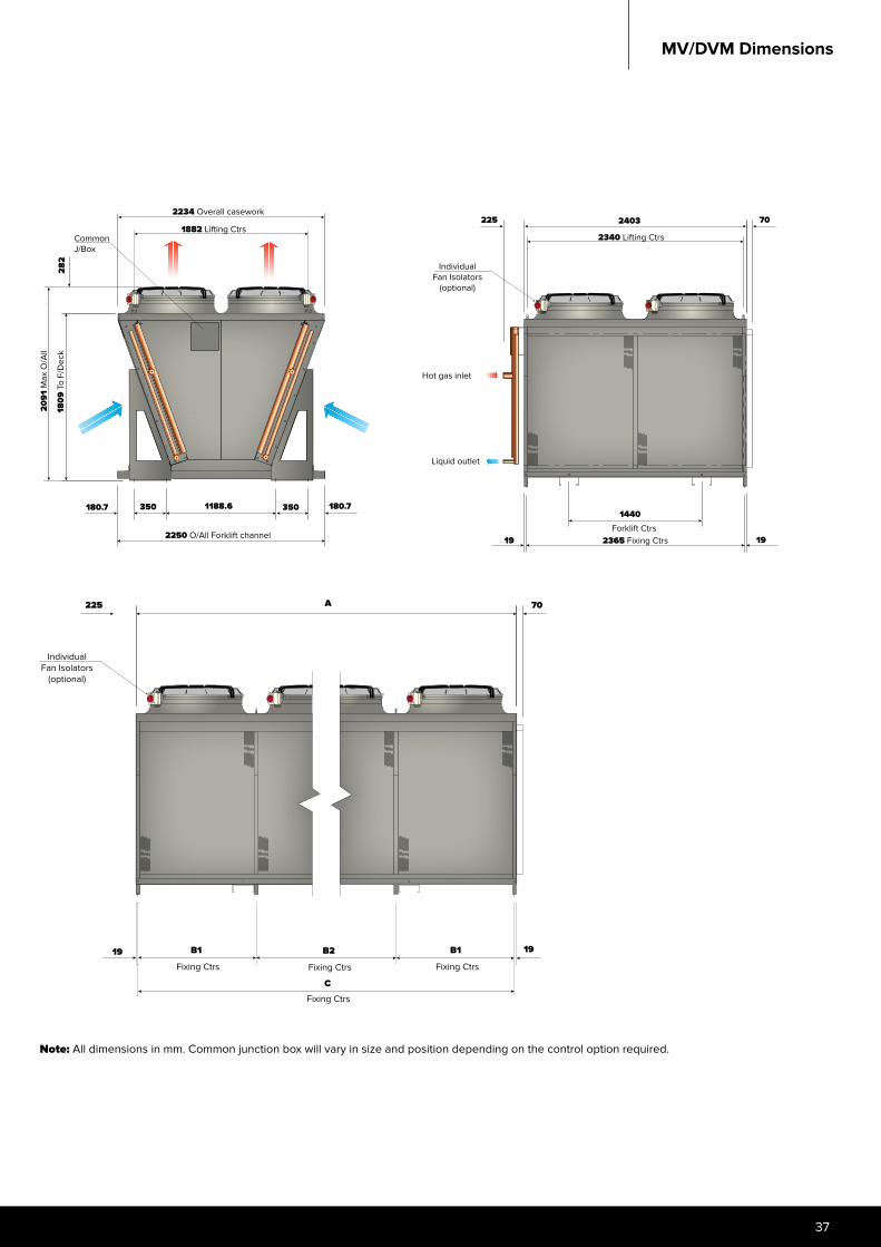
MV/DVM Dimensions
Note: All dimensions in mm. Common junction box will vary in size and position depending on the control option required.
IndividualFan Isolators
(optional)
225 70
1919Fixing Ctrs
B1
Fixing Ctrs
B2
Fixing Ctrs
B1
Fixing Ctrs
C
A
282
2234 Overall casework
CommonJ/Box
1882 Lifting Ctrs
2091
Max
O/A
ll
1809
To
F/D
eck
2250 O/All Forklift channel
180.7 350 1188.6 350 180.7
225 2403
2340 Lifting Ctrs
70
IndividualFan Isolators
(optional)
Hot gas inlet
Liquid outlet
1440Forklift Ctrs
2365 Fixing Ctrs19 19
Searle Air cooled Condenser , Dry Cooler and Gas cooler
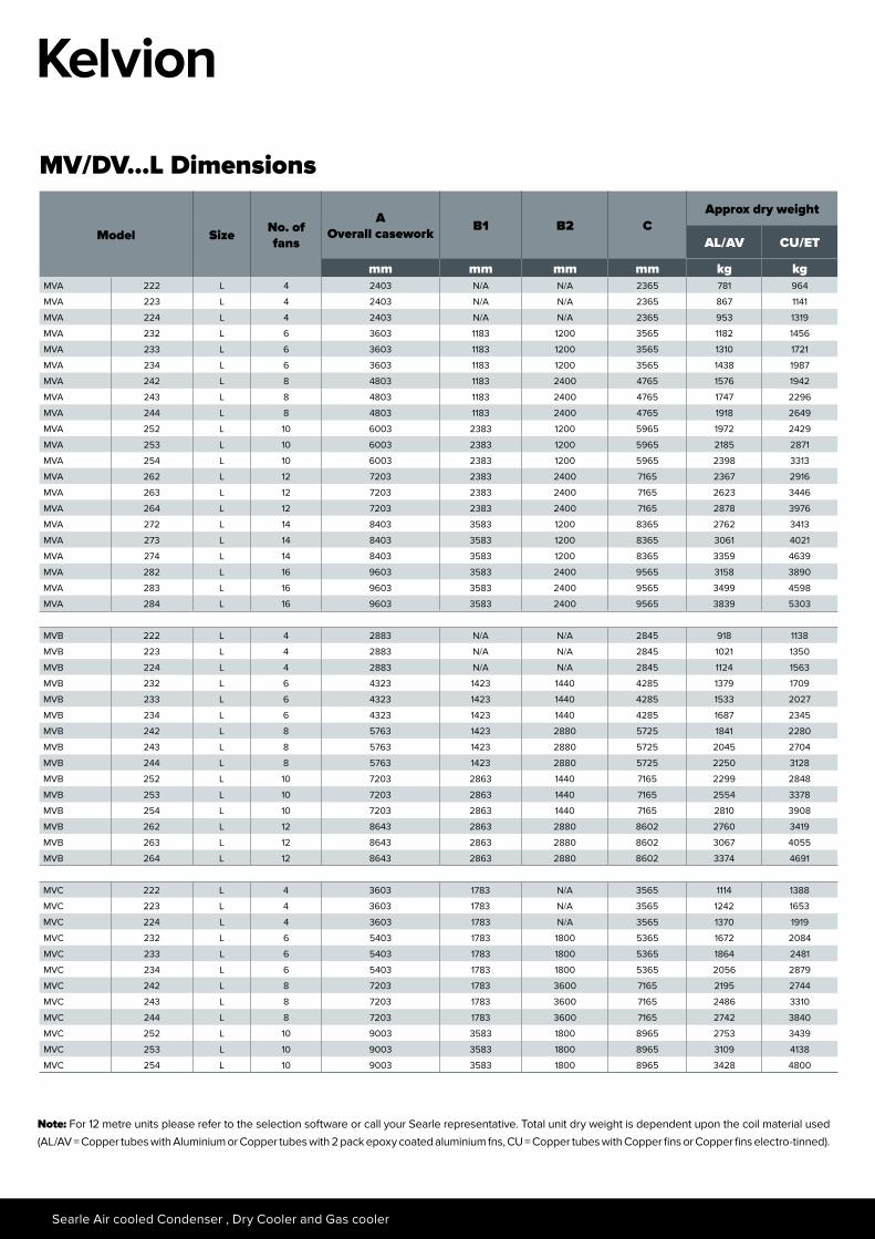
Model Size No. of fans
AOverall casework B1 B2 C
Approx dry weight
AL/AV CU/ET
mm mm mm mm kg kgMVA 222 L 4 2403 N/A N/A 2365 781 964
MVA 223 L 4 2403 N/A N/A 2365 867 1141
MVA 224 L 4 2403 N/A N/A 2365 953 1319
MVA 232 L 6 3603 1183 1200 3565 1182 1456
MVA 233 L 6 3603 1183 1200 3565 1310 1721
MVA 234 L 6 3603 1183 1200 3565 1438 1987
MVA 242 L 8 4803 1183 2400 4765 1576 1942
MVA 243 L 8 4803 1183 2400 4765 1747 2296
MVA 244 L 8 4803 1183 2400 4765 1918 2649
MVA 252 L 10 6003 2383 1200 5965 1972 2429
MVA 253 L 10 6003 2383 1200 5965 2185 2871
MVA 254 L 10 6003 2383 1200 5965 2398 3313
MVA 262 L 12 7203 2383 2400 7165 2367 2916
MVA 263 L 12 7203 2383 2400 7165 2623 3446
MVA 264 L 12 7203 2383 2400 7165 2878 3976
MVA 272 L 14 8403 3583 1200 8365 2762 3413
MVA 273 L 14 8403 3583 1200 8365 3061 4021
MVA 274 L 14 8403 3583 1200 8365 3359 4639
MVA 282 L 16 9603 3583 2400 9565 3158 3890
MVA 283 L 16 9603 3583 2400 9565 3499 4598
MVA 284 L 16 9603 3583 2400 9565 3839 5303
MVB 222 L 4 2883 N/A N/A 2845 918 1138
MVB 223 L 4 2883 N/A N/A 2845 1021 1350
MVB 224 L 4 2883 N/A N/A 2845 1124 1563
MVB 232 L 6 4323 1423 1440 4285 1379 1709
MVB 233 L 6 4323 1423 1440 4285 1533 2027
MVB 234 L 6 4323 1423 1440 4285 1687 2345
MVB 242 L 8 5763 1423 2880 5725 1841 2280
MVB 243 L 8 5763 1423 2880 5725 2045 2704
MVB 244 L 8 5763 1423 2880 5725 2250 3128
MVB 252 L 10 7203 2863 1440 7165 2299 2848
MVB 253 L 10 7203 2863 1440 7165 2554 3378
MVB 254 L 10 7203 2863 1440 7165 2810 3908
MVB 262 L 12 8643 2863 2880 8602 2760 3419
MVB 263 L 12 8643 2863 2880 8602 3067 4055
MVB 264 L 12 8643 2863 2880 8602 3374 4691
MVC 222 L 4 3603 1783 N/A 3565 1114 1388
MVC 223 L 4 3603 1783 N/A 3565 1242 1653
MVC 224 L 4 3603 1783 N/A 3565 1370 1919
MVC 232 L 6 5403 1783 1800 5365 1672 2084
MVC 233 L 6 5403 1783 1800 5365 1864 2481
MVC 234 L 6 5403 1783 1800 5365 2056 2879
MVC 242 L 8 7203 1783 3600 7165 2195 2744
MVC 243 L 8 7203 1783 3600 7165 2486 3310
MVC 244 L 8 7203 1783 3600 7165 2742 3840
MVC 252 L 10 9003 3583 1800 8965 2753 3439
MVC 253 L 10 9003 3583 1800 8965 3109 4138
MVC 254 L 10 9003 3583 1800 8965 3428 4800
MV/DV...L Dimensions
Note: For 12 metre units please refer to the selection software or call your Searle representative. Total unit dry weight is dependent upon the coil material used (AL/AV = Copper tubes with Aluminium or Copper tubes with 2 pack epoxy coated aluminium fns, CU = Copper tubes with Copper fins or Copper fins electro-tinned).
39
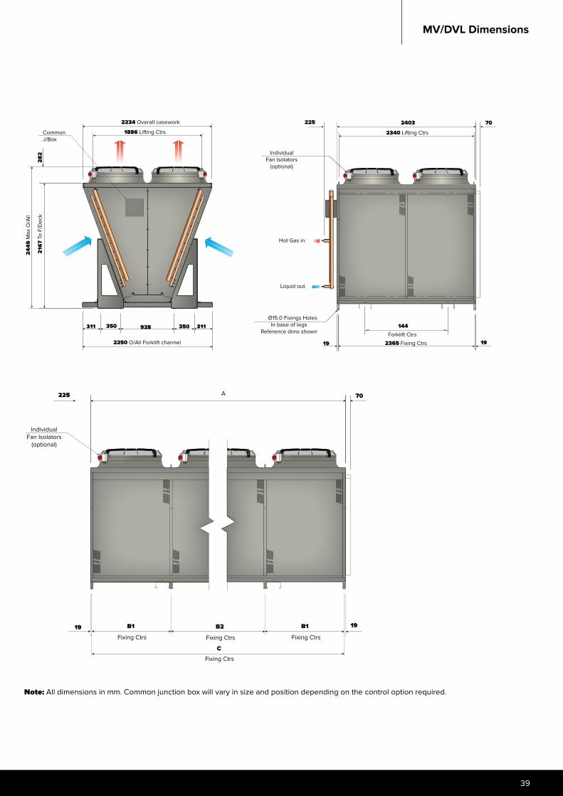
MV/DVL Dimensions
IndividualFan Isolators
(optional)
225 70
1919Fixing Ctrs
B1
Fixing Ctrs
B2
Fixing Ctrs
B1
Fixing Ctrs
C
A
225 70
2340 Lifting Ctrs
2403
IndividualFan Isolators
(optional)
Hot Gas in
Liquid out
Ø15.0 Fixings HolesIn base of legs
Reference dims shown
19 19
144Forklift Ctrs
2365 Fixing Ctrs
2234 Overall casework
1886 Lifting CtrsCommonJ/Box
282
311350928350311
2250 O/All Forklift channel
2449
Max
O/A
ll
2167
To
F/D
eck
Note: All dimensions in mm. Common junction box will vary in size and position depending on the control option required.

www.kelvion.com
Kelv
ion
Con
dens
er &
Dry
coo
ler I
nsta
llatio
n an
d m
aint
enan
ce,
May
3 2
016
272
-00
0-0
05