Embed Size (px)
Citation preview
Stainless Steel Evaporative Condenser / Fluid-Cooler
Installation and Operation Manual
A New Concept in Evaporative Cooling
2 3
Güntner, a German multinational company with over 80 years of “know-
how” and world leader in development of heat exchanger technologies
presents the ECOSS (Evaporative Condenser Stainless Steel)
a new concept in evaporative condensing.
The ECOSS is an innovative technology that has emerged from the Güntner
Group. The ECOSS meets all requirements for thermal performance, quality,
safety, environment and reliability. Its thermal and operational performance
is tried and tested according to ANSI / ASHRAE 64-2011 in Güntner’s own
laboratory, the EC LAB (Evaporative Condenser Laboratory).
The EC-LAB is the only laboratory in the Southern Hemisphere with the
ability to simulate climatic conditions for evaporative products, adiabatic
tests, dry coolers, air condensers and heat exchangers. This technology center
was developed through international partnership between the companies
Güntner, Güntner Brazil and Güntner USA. This significant investment will
provide Güntner customers with proven equipment performance and
warranty.
The Installation and Operating Manual or short IOM, among other
documentation should always be available for your reference. If you have
questions or are in need of spare parts, please contact the Commercial
Department of Güntner, which will strive to meet your needs in a speedy and
effective fashion.
Index
1. Responsibilities 6
1. Manufacturer’s Responsibilities 7
2. Owner/Operator’s Responsibilities. 7
3. Legal Notes 8
4. Operational Notes 9
2. Safety 10
1. Warning Labels and Signs 13
2. Basic Safety 13
3. Mechanical Waste and Hazards 16
4. Residual Electrical Hazards 17
5. Residual Thermal Hazards 17
6. Residual Hazards when working with
Refrigerants 18
7. Residual Hazards when working with Refrigerant
and general Vibration 18
8. Combined Residual Hazards 19
3. Components 20
1. AC Technology (Alternating Current) 21
2. EC Technology (Electronically Commutated) 23
3. Water Pump 26

4. Transportation and Storage 28
1. Safety 29
2. Transport 29
3. Storage 29
4. Packaging 30
5. Module Handling and Assembly 31
4 5
5. Installation 32
1. Additional Information during Installation 33
2. Connection of Water Pipe Tray 33
3. Connecting unit to System 33
4. Performance and Acceptance Test 38
5. Readiness of Operation 40
6. First Time Running Operation 40
7. Disassembling the Unit 41
8. Shutdown Procedure 41
9. Unit Startup after Shutdown 42
10. Fluid Changes 43
6. Fault Diagnosis 44
1. Safety 45
2. Troubleshooting 45
7. Maintenance 46
1. Safety 47
2. Maintenance Procedures 49
3. Recommended Maintenance Intervals 51
4. Cleaning the ECOSS 55
8. Purging and Water Treatment 58
1. Draining Water (Transfer and De-Concentration) .. 59
2. Water Quality Parameters 60
Responsibilities
6 7
Condensers
Evaporators /
Fluid Coolers
1.1 Responsibilities of the manufacturer
The observations given in these instructions for maintaining functional
safety of the equipment, avoiding possible hazards during transportation,
assembly and installation, startup and operation, and the maintenance
activities (cleaning, repairs and technical assistance) refer only to the unit,
and do not apply to other series of equipment or equipment from other
manufacturers.
Construction materials are configured such as that they resist foreseeable
mechanical, thermal and chemical stresses and are resistant to fluids and
mixtures of fluids or oils and coolants as outlined in the specifications.
The welded parts containing fluids (central tube, headers or distributors) are
designed to withhold caustic chemicals (see specifications), mechanical or
thermal stress and to resist the maximum allowable working pressure
(MAWP).
Materials, wall thickness of tubes (central, headers, distributors and
collectors), tensile strength, corrosion resistance (during testing) are
suitable for fluids (defined in the specifications) to resist design pressures,
voltages and temperatures.
1.2 Owner / Operator Responsibilities
The owner and or operator shall verify that the all operational staff are
trained and skilled enough to operate, monitor and perform service on the
equipment / system.
Operational staff should have sufficient knowledge and experience with
relation to the mode of operation as well as daily monitoring of this system.
Before starting the system, the owner or operator responsible should check
that the operating personnel are sufficiently informed with respect to the
product documentation (operating instructions) system configuration,
monitoring, operation and technical assistance, safety measures, and with
respect to the properties and handling of refrigerants to be used.
The owner or operator responsible must properly operate, monitor and
perform maintenance on the system. He or she must ensure that fluids
should not be changed or substituted with fluids not specified in the project
document; exception only by authorization from Güntner.

Planning and preparing emergency measures: A suitable warning system
should be installed on owner’s premises to avoid consequential damage
caused by operational disturbances or if failures occur. Emergency
measures should be in place to prevent consequential damage to persons
and equipment.
Owner or operator (as specified in project documents) shall be responsible
in case the equipment is used by third parties (not specified in project
documents), unless a prior agreement with Güntner has been made.
1.3 Legal Notes
A warranty claim will expire upon the following:
•Any defects and damages due to non-conformances as outlines in the
specifications or operating instructions;
•Any claims due to usage of non-original manufacturers’ parts or
replacement parts not specified in the proposal or project documents;
•Any unapproved changes to the unit (refrigerants, function parameters,
operational changes, etc.) in relation to specifications or project documents
or related to the application design without authorization Güntner;
•The operating instructions shall not be reproduced, circulated,
amended, passed on to third parties translated or otherwise used, in
whole or in part without the express written permission of Güntner.
1.4 Remarks to Operations - Attention
These operating instructions apply to all models of ECOSS evaporative
condensers for operation in accordance with the recommended fluids,
pressures and temperatures specified in the project documents.
You will find the parameters and the exact model of your equipment in
project documents related to the application; if you do not have the same,
please contact the Güntner technical team.
1.4.1 Documentation- Attention
The operating instructions of the unit include the following items:
•Equipment Guide (shipping instructions, assembly, operation and
maintenance manual);
• Documents related to the project application:
-Description regarding technicians trained in the proper use of equipment;
-Drawings of the equipment related to the application, specifying the
client, project number and the application number;
- Electrical Motor circuit diagram.
It is the customer‘s responsibility to request the aforementioned
documentation above.
WARNING
WARNING
8 9
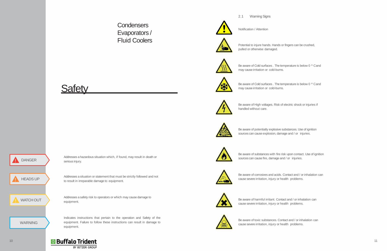
2.1 Warning Signs
Notification / Attention
Potential to injure hands. Hands or fingers can be crushed,
pulled or otherwise damaged.
Be aware of Cold surfaces . The temperature is below 0 º C and
may cause irritation or cold-burns.
Be aware of Cold surfaces . The temperature is below 0 º C and
may cause irritation or cold-burns.
Be aware of High voltages. Risk of electric shock or injuries if
handled without care.
Be aware of potentially explosive substances. Use of ignition
sources can cause explosion, damage and / or injuries.
Be aware of substances with fire risk upon contact. Use of ignition
sources can cause fire, damage and / or injuries.
Be aware of corrosives and acids. Contact and / or inhalation can
cause severe irritation, injury or health problems.
Be aware of harmful irritant. Contact and / or inhalation can
cause severe irritation, injury or health problems.
Be aware of toxic substances. Contact and / or inhalation can
cause severe irritation, injury or health problems.
Addresses a hazardous situation which, if found, may result in death or
serious injury.
Addresses a situation or statement that must be strictly followed and not
to result in irreparable damage to equipment.
Addresses a safety risk to operators or which may cause damage to
equipment.
Indicates instructions that pertain to the operation and Safety of the
equipment. Failure to follow these instructions can result in damage to
equipment.
DANGER!
HEADS UP!
WARNING
WATCH OUT!
10 11
Safety
Condensers
Evaporators /
Fluid Coolers
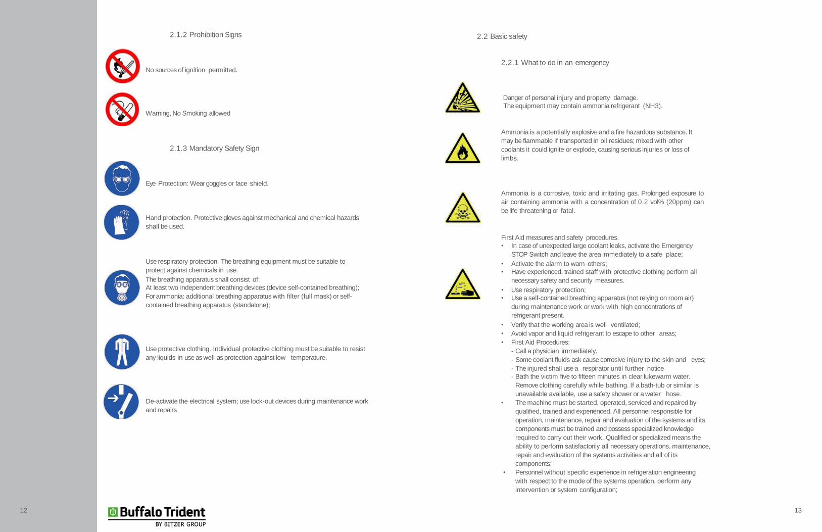
2.2 Basic safety
2.2.1 What to do in an emergency
Ammonia is a potentially explosive and a fire hazardous substance. It
may be flammable if transported in oil residues; mixed with other
coolants it could ignite or explode, causing serious injuries or loss of
limbs.
Ammonia is a corrosive, toxic and irritating gas. Prolonged exposure to
air containing ammonia with a concentration of 0.2 vol% (20ppm) can
be life threatening or fatal.
First Aid measures and safety procedures.
• In case of unexpected large coolant leaks, activate the Emergency
STOP Switch and leave the area immediately to a safe place;
• Activate the alarm to warn others;
• Have experienced, trained staff with protective clothing perform all
necessary safety and security measures.
• Use respiratory protection;
• Use a self-contained breathing apparatus (not relying on room air)
during maintenance work or work with high concentrations of
refrigerant present.
• Verify that the working area is well ventilated;
• Avoid vapor and liquid refrigerant to escape to other areas;
• First Aid Procedures:
- Call a physician immediately.
- Some coolant fluids ask cause corrosive injury to the skin and eyes;
- The injured shall use a respirator until further notice
- Bath the victim five to fifteen minutes in clear lukewarm water.
Remove clothing carefully while bathing. If a bath-tub or similar is
unavailable available, use a safety shower or a water hose.
• The machine must be started, operated, serviced and repaired by
qualified, trained and experienced. All personnel responsible for
operation, maintenance, repair and evaluation of the systems and its
components must be trained and possess specialized knowledge
required to carry out their work. Qualified or specialized means the
ability to perform satisfactorily all necessary operations, maintenance,
repair and evaluation of the systems activities and all of its
components;
• Personnel without specific experience in refrigeration engineering
with respect to the mode of the systems operation, perform any
intervention or system configuration;
2.1.2 Prohibition Signs
No sources of ignition permitted.
Danger of personal injury and property damage.
The equipment may contain ammonia refrigerant (NH3).Warning, No Smoking allowed
2.1.3 Mandatory Safety Sign
Eye Protection: Wear goggles or face shield.
Hand protection. Protective gloves against mechanical and chemical hazards
shall be used.
Use respiratory protection. The breathing equipment must be suitable to
protect against chemicals in use.
The breathing apparatus shall consist of:
At least two independent breathing devices (device self-contained breathing);
For ammonia: additional breathing apparatus with filter (full mask) or self-
contained breathing apparatus (standalone);
Use protective clothing. Individual protective clothing must be suitable to resist
any liquids in use as well as protection against low temperature.
De-activate the electrical system; use lock-out devices during maintenance work
and repairs
12 13
1514
• Any changes to the units original manufacturers start-up parameters
have to be first authorized in writing and may only be performed by
trained and qualified personnel;
• Electrical installation: Work on electrical equipment may only be
performed by people who have the specific knowledge required (eg,
an electrician, or a person trained in electrical engineering), and are
authorized by the operator in accordance with all respective safety
regulations and PPE.
2.2.2 Use an overall Adequate Design
The ECOSS evaporative condenser / liquid cooler series are intended for
installation in a refrigeration system and are used for cooling / condensation
in large refrigeration systems, such as in meat plants, slaughterhouses, food
industry, beverage, power industry, and other applications. The unit is
delivered for operation with a specific operating point:
• Temperature / Condensation Pressure;
• Air flow rates;
• Mass flow of gas / liquid, volumetric flow rate;
• Wet bulb temperature of inlet air;
• Altitude;
• Thermal capacity.
You will find the parameters and the exact model of your equipment in the
related project documents. In case you do not have them,WARNING
2.2.3 OperatingConditions
• The equipment is a component of a refrigeration system including all
coolant fluids. The purpose of this manual, as part of the operating
instructions manual (which are part of these operating instructions), is
to minimize hazards to people, property and the environment of the
unit and all its components including coolant fluids being used . These
risks are mainly related to the physical and chemical properties of the
coolant fluids and with the pressures and temperatures that occur in
the components carrying the coolant fluids in the equipment. Refer to
the respective MSDS of compounds (Material Safety Data
Sheet of chemicals) available from your suppliers. The MSDS contains
additional information regarding your specific refrigerant as well as its
characteristics and dangers and safety measures.
• The equipment may only be used in accordance with proper intended.
During operation the operator shall monitor all relevant data as to
manufactures recommendations and not allow deviations of measured
data to be out of permissible range. The operator may use this data
to advance maintenance procedures as outlined in the manufactures
recommended maintenance intervals.
• The operator shall verify that the maintenance measures are being
carried out according to the operating manual of the system and / or
additional instructions from the manufacturer.
• Do not exceed the MAWP (Manufactures recommended Working
Pressures as specified on the nameplate and /or otherwise specified in
the project documents.
2.2.4 Misuse and deviations from design
Coolant fluids and their combinations with water and other substances in
the components carrying the Coolant fluids has chemical and physical
effects within the materials surrounding them. The unit shall only be
pressurized with the compound defined in related project documents. High
pressures with another coolant fluids and / or liquids or solids may result in:
• If modified or replaced, structural and other welding joints or materials
may not withstand the mechanical, thermal and chemical tensions and
pressures (as per design) during operation; frequent shutdowns or
undesirable operation may occur.
• The materials, wall thickness, tensile strength, corrosion resistance
and process tests are suitable for the coolant fluid (as per design) and
may not resist the possible variations of stresses and strains that may
occur;
• The ECOSS may not operate as designed for other coolant fluids unless
otherwise specified in the project documents and / or specifications or
otherwise authorized by Güntner;
• The ECOSS may not remain watertight during operation while
disconnected from the system or plant;
• A sudden escape of coolant fluids may harm persons and / or property
and / or the environment.

Specified pressures (Maximum allowable working pressures / MAWP) or
other design parameters as mentioned on the nameplate as well as in the
documentation shall not be exceeded! If the working pressure is exceeded:
1. Structural and other welding joints or materials may not withstand the
mechanical, thermal and chemical tensions and pressures (as per
design) during operation; frequent shutdowns or undesirable operation
may occur;
2. The ECOSS may not remain watertight during operation while
disconnected from the system or plant;
3. A sudden escape of coolant fluids do to pipe / tube leaks may have
following risks:
• Hazardous materials leak;
• Risk of poisoning;
• Risk of fire;
• Risk of explosion;
• Risk of chemical burns;
• Risk of suffocation;
• Hazards caused by panic reactions;
• Environmental Pollution.
2.3.1 Tables, corners and sharp edges of equipment
Be aware of hand or limb injuries. Risk of cuts to hand, fingers
and limbs caused by sharp edges and corners of equipment.
Use correct PPE (Personal Protection Equipent) such as gloves
2.3.2 Misuse, deviations from design
Risk of losing limbs. Risk of injuries to hand and limbs by spinning
fan blades or other moving parts. Wear PPE to protect hair and
clothing etc.
Do not operate fans without Fan-Guard. Automatic Starting of fans
during operation or maintenance may hold a risk of personal
injuries. Stay clear of rotating parts.
Turn off and unplug the equipment before starting maintenance
work when removing fan-guard is necessary. Protect the unit
against unintentional restart by using Lock-Out procedures
by locks or removal of applicable electrical fuses of the unit.
Protect the unit with an adequate sign that work is in progress
to prevent unintentional starting. Fans should be opened only
by trained personnel using adequate tools and only for the purpose
of maintenance and repairs. Re-install fan guards after completing
the work, and protect them against unintentional or unauthorized
opening! Make sure electricity is disconnected before removal of
safety-bolt!
Beware of hinged side plates. These should only be opened
by trained personnel with proper tools, and only for the
purpose of maintenance and repairs. Close the hinged side plates
after completing the work, and protect them against unintentional
or unauthorized opening!
Attention
Maintenance work on fan blades should only be done with fan
power disconnected and proper protection in place.
2.3 Mechanical hazards waste
2.4 Electrical Hazards
2.4.1 Fans, electric motors, water pumps and electric box
High Voltage Risks
The direct and indirect contact with parts carrying a voltage
such as motors and electrical lines can cause serious injury
or death. Unplug the unit before starting maintenance work.
To do so, see the cooling system documentation. Protect the unit
against unintentional restart by removing the electric fuses or
‘lock-out’ of the unit. Protect the unit with an adequate warning
sign to prevent unintentional starting.
Note that the network cables may also be carrying voltage, even
if the unit is turned off. Work on electrical equipment may
only be performed by trained technicians with sufficient knowledge
to perform the required work (for example, an electrician, or
a person trained in electrical engineering), and are authorized by
the responsible operator.
HEADS UP
16 17

2.5. Residual thermal hazards
2.5.1. Risk of burns
Be aware of hot surfaces during an electrical service, heat
exchanger tubes and piping (hot gas) and any other parts of the
equipment that may carry residual heat. Any temperatures above
+45 °C may cause burns.
Use proper PPE Equipment such as gloves.
2.6. Residual Refrigerant Hazards
2.7. Perigos residuais com refrigerante causados por vibrações
These risks are mainly related to the physical and chemical properties of the
coolant fluid and with the pressures and temperatures that occur in the
components carrying the coolant fluid in the equipment. Refer to the respective
MSDS of compounds (Material Safety Data Sheet of caustic chemicals and
refrigerants) available from your suppliers. The MSDS contains additional
information regarding your specific coolant fluids as well as its characteristics
and dangers.
DANGER!
If the fans are damaged during the operation, loose fan blade parts can injury to
persons and / or damage to property. Fans, cables and components in the
system are designed, constructed and integrated to prevent hazards caused by
individual vibration or vibration by other parts of the system.
Excessive vibration caused by imbalance of fan blades may be due to dirt or
damage to fan assembly and are transferred to the unit where additional
damage to unit or injury to personnel may occur.
Check the propellers and the guardrail or fan guards regularly to be free of dirt or
scale formation to assure and smooth fan operation.
DANGER!
2.8. Combined residual hazards
2.8.1. Hinged Side Panels and Plates
Beware of hot surfaces
Temperatures above 45 º C and can cause severe burns.
Risk of injury to hands and limbs
Opening removable side panels may expose hot surfaces or
sharp edges. Take precaution to prevent scalding of skin by
hot surfaces or cuts of hands due to sharp edges. Removable side
plates should be opened only by trained personnel with proper
tools, and only for the purpose of maintenance and repairs. Close
removable side plates after completing the work, and protect them
against unintentional or unauthorized opening.
18 19
Components
Condensers
Evaporators /
Fluid Coolers
3.1. AC Technology (see annex for details)
• In terms of aerodynamics, axial fans have the highest level of
technology and performance in the market. They are designed
to deliver highest performance in terms of throughput with low
backpressure and low noise;
• Corresponding delays must be taken into account in the case of star /
delta connection;
• if frequency inverters for speed control are being used following items
should be observed for fan motors:
A sine-wave filter must be installed on all poles between the frequency
inverter and the motor, (Effect output voltage filter with sinusoidal shape
between phase to phase and phase to ground), observe Figure 1.
Alternative control with Güntner note figure 2; Three phase fan motors can
be operated by means of a star / delta connection with two speeds design
and / or speed control. The direction of rotation must be checked. If the
direction is wrong, it can be changed by interchanging the two phases.
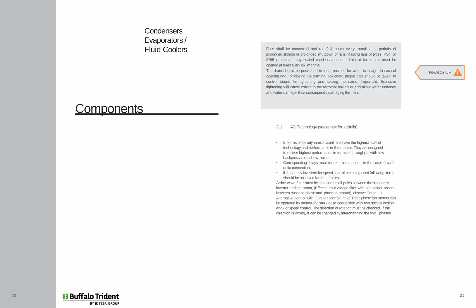
Fans shall be connected and ran 2-4 hours every month after periods of
prolonged storage or prolonged shutdown of fans. If using fans of types IP54 or
IP55 protection, any sealed condensate outlet drain at fan motor must be
opened at least every six months.
The drain should be positioned in ideal position for water drainage. In case of
opening and / or closing the terminal box cover, proper care should be taken to
control torque for tightening and sealing the same. Important: Excessive
tightening will cause cracks to the terminal box cover and allow water entrance
and water damage, thus consequently damaging the fan.
HEADS UP !
20 21
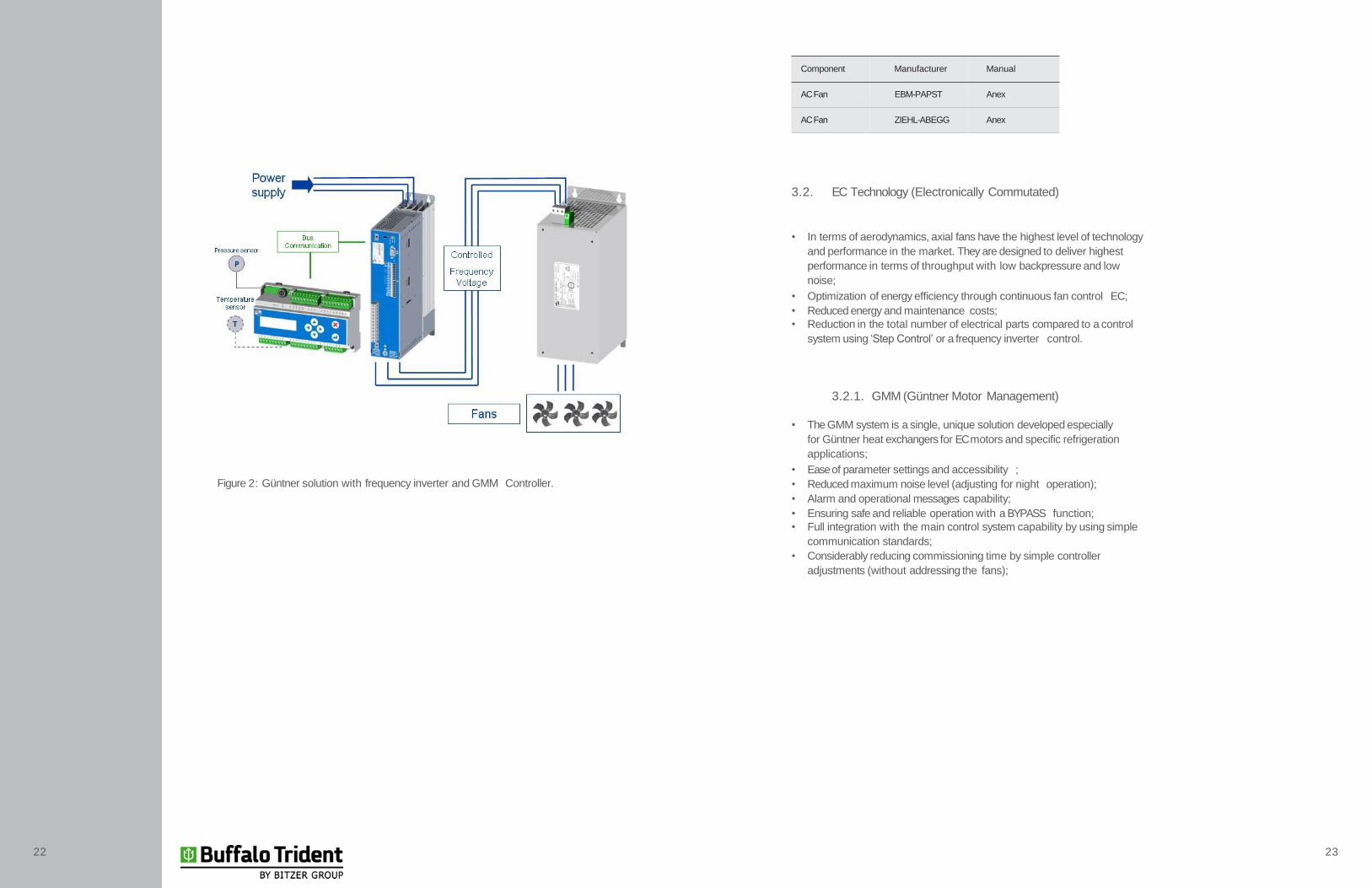
Figure 2: Güntner solution with frequency inverter and GMM Controller.
Component Manufacturer Manual
ACFan EBM-PAPST Anex
ACFan ZIEHL-ABEGG Anex
3.2. EC Technology (Electronically Commutated)
• In terms of aerodynamics, axial fans have the highest level of technology
and performance in the market. They are designed to deliver highest
performance in terms of throughput with low backpressure and low
noise;
• Optimization of energy efficiency through continuous fan control EC;
• Reduced energy and maintenance costs;
• Reduction in the total number of electrical parts compared to a control
system using ‘Step Control’ or a frequency inverter control.
3.2.1. GMM (Güntner Motor Management)
• The GMM system is a single, unique solution developed especially
for Güntner heat exchangers for EC motors and specific refrigeration
applications;
• Ease of parameter settings and accessibility ;
• Reduced maximum noise level (adjusting for night operation);
• Alarm and operational messages capability;
• Ensuring safe and reliable operation with a BYPASS function;
• Full integration with the main control system capability by using simple
communication standards;
• Considerably reducing commissioning time by simple controller
adjustments (without addressing the fans);
22 23
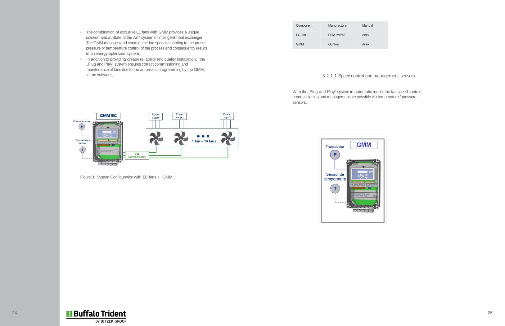
• The combination of exclusive EC fans with GMM provides a unique
solution and a „State of the Art” system of intelligent heat exchanger.
The GMM manages and controls the fan speed according to the preset
pressure or temperature control of the process and consequently results
in an energy-optimized system;
• In addition to providing greater reliability and quality installation, the
„Plug and Play“ system ensures correct commissioning and
maintenance of fans due to the automatic programming by the GMM,
ie, no software,
Figure 3: System Configuration with EC fans + GMM.
Component Manufacturer Manual
ECFan EBM-PAPST Anex
GMM Güntner Anex
3.2.1.1 Speed control and management sensors
With the „Plug-and-Play“ system in automatic mode, the fan speed control,
commissioning and management are possible via temperature / pressure
sensors.
24 25
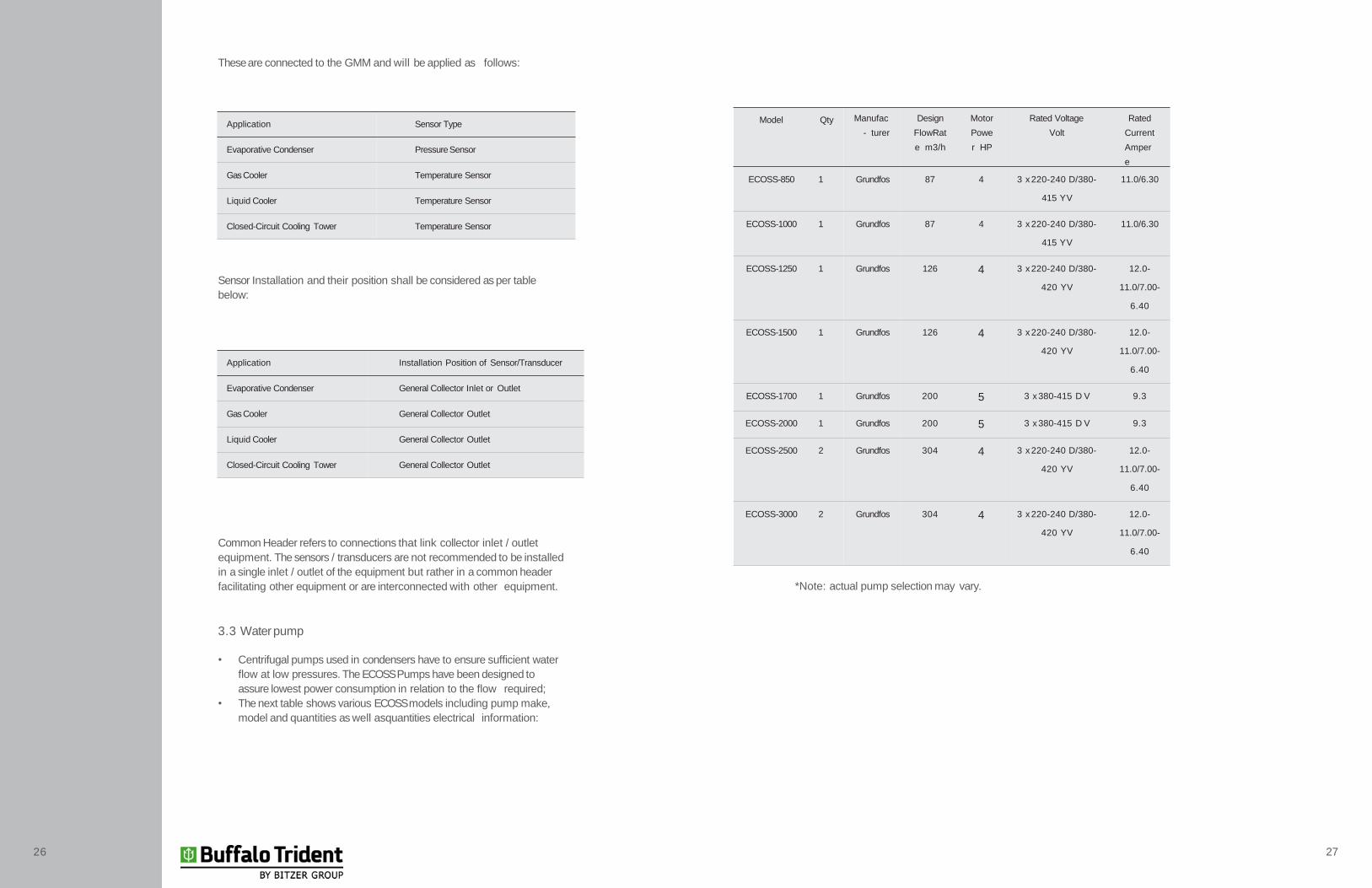
*Note: actual pump selection may vary.
26 27
Model Qty Manufac
- turer
Design
FlowRat
e m3/h
Motor
Powe
r HP
Rated Voltage
Volt
Rated
Current
Amper
e
ECOSS-850 1 Grundfos 87 4 3 x 220-240 D/380-
415 YV
11.0/6.30
ECOSS-1000 1 Grundfos 87 4 3 x 220-240 D/380-
415 YV
11.0/6.30
ECOSS-1250 1 Grundfos 126 4 3 x 220-240 D/380-
420 YV
12.0-
11.0/7.00-
6.40
ECOSS-1500 1 Grundfos 126 4 3 x 220-240 D/380-
420 YV
12.0-
11.0/7.00-
6.40
ECOSS-1700 1 Grundfos 200 5 3 x 380-415 D V 9.3
ECOSS-2000 1 Grundfos 200 5 3 x 380-415 D V 9.3
ECOSS-2500 2 Grundfos 304 4 3 x 220-240 D/380-
420 YV
12.0-
11.0/7.00-
6.40
ECOSS-3000 2 Grundfos 304 4 3 x 220-240 D/380-
420 YV
12.0-
11.0/7.00-
6.40
These are connected to the GMM and will be applied as follows:
Sensor Installation and their position shall be considered as per table
below:
Common Header refers to connections that link collector inlet / outlet
equipment. The sensors / transducers are not recommended to be installed
in a single inlet / outlet of the equipment but rather in a common header
facilitating other equipment or are interconnected with other equipment.
3.3 Waterpump
• Centrifugal pumps used in condensers have to ensure sufficient water
flow at low pressures. The ECOSS Pumps have been designed to
assure lowest power consumption in relation to the flow required;
• The next table shows various ECOSS models including pump make,
model and quantities as well asquantities electrical information:
Application Sensor Type
Evaporative Condenser PressureSensor
Gas Cooler Temperature Sensor
Liquid Cooler Temperature Sensor
Closed-Circuit Cooling Tower Temperature Sensor
Application Installation Position of Sensor/Transducer
Evaporative Condenser General Collector Inlet or Outlet
Gas Cooler General Collector Outlet
Liquid Cooler General Collector Outlet
Closed-Circuit Cooling Tower General Collector Outlet
Transport and Storage
Condensers
Evaporators /
Fluid Coolers
4.1 Safety
• Improper Handling;
• All models weigh between 1000 kilogram and 4,000 kilogram
respectively (combined weight of top and bottom). Top and/ or Bottom
may slip or fall if handled improperly during transport possibly causing
serious injury or even death. Erratic movement or strong vibrations
during transport may damage the unit;
• Only have experienced personnel load or unload or handle the unit
during transport.
• Use appropriate means of transport or handling capable of proper
weight distribution. Necessary weight specifications are available in
your project documents. Keep unit clear during loading or transport to
prevent injuries.
• Maintain even weight distribution during transport. Follow the
instructions on the shipping labels for special handling instructions (if
applicable);
• Keep unit away from hazardous areas to prevent damage to property
and personnel.
• Using a crane: Connect hooks, shackles or any other lifting devices
secured only at the lifting points as specified by the manufacturer;
• Use auxiliary transport equipment when necessary. Only use
appropriate transport vehicles capable of handling specified loads;
• Do connect any lifting devices to pipes, headers, pull plates, casing
etc. as there are not designed for load handling;
• Transport the unit carefully. Avoid sudden movments.
4.2 Transport
• Read and observe transport instructions;
• Excessive vibrations caused by uneven road surfaces, potholes during
transport may cause equipment damage;
• Only load or unload with suitable equipment (crane, hoist, crane, etc)
unit;
• The equipment may only be transported with original packaging design
to assure adequate for protection.
4.3. Storage
• Avoid possibility of corrosion or undesirable dirt accumulation during
storage;
• Protect the unit against dust, dirt, moisture, pollution and other
contaminations;
• Do not store the unit any longer than necessary;
• Only store the units in their original packaging;
HEADS UP !
DANGER !
28 29
• Only stack units of same size and in their original packaging, consult
your Güntner partner for clarification;
• Store the unit in a protected location away from dust, dirt, moisture and
contamination-free until the time of installation (enclosed storage);
• Unexpected installation delay: protect the unit from the elements, dirt
and other contaminants with adequate coverage.
4.4. Packing
• The units are packaged as to their respective installation position;
• Remove all packing including special protection for all drive modules
(if applicable)before installation;
• Caution! Transport or lifting devices shall be rated minimum 1,5 times
the weight of the ECOSS;
• Verify Packing list at the time of delivery / unloading. Packing list and
instructions are also part of the project documents.
• Any damage during transport shall be properly; inform manufacturer
immediately along with proper documentation.
• Unit is send from manufacture in a pressurized condition (compressed
dry air). Refer to project documentation and / or refer label at unit inlet
piping. Verify existing pressure at Schrader valve and contact
• Check the pressure as indicated in
manufacturer of any discrepancies;
Fugure 4. Do not install the unit if
lower pressure is detected. Lower pressure may indicate a leak
and thus shall not be installed; condensing fluids may be hazardous
when in contact with skin or inhaled by personell. Contact
manufacturer immediately.
1 - Remove protecting caps
2 - Verify existing pressure and take a note
HEADS UP!
4.5 Handling and assembly of modules
The movement of equipment modules must be performed by suitable
means (crane, hoist, etc)., Take weight and size of the unit in
consideration.
Do not use connecting parts or piping including headers to lift, pull, fix or
assemble. Doing so may cause leaks!
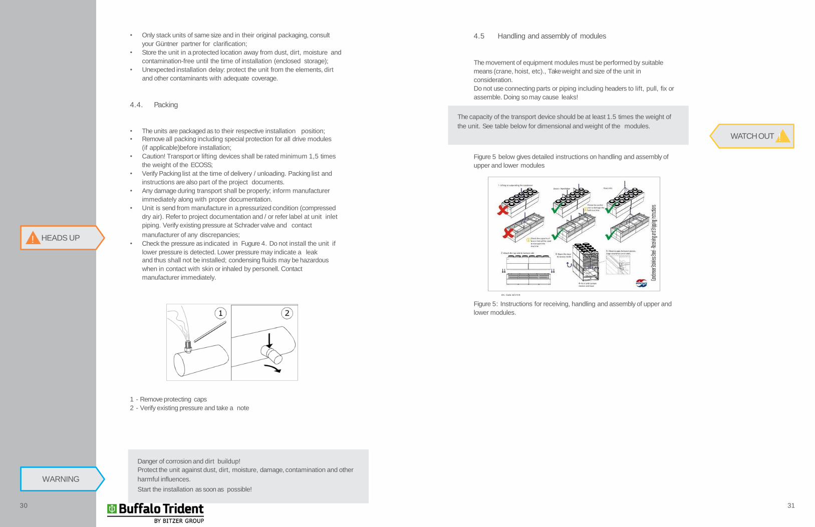
Figure 5 below gives detailed instructions on handling and assembly of
upper and lower modules
Figure 5: Instructions for receiving, handling and assembly of upper and
lower modules.
Danger of corrosion and dirt buildup!
Protect the unit against dust, dirt, moisture, damage, contamination and other
harmful influences.
Start the installation as soon as possible!
The capacity of the transport device should be at least 1.5 times the weight of
the unit. See table below for dimensional and weight of the modules.
WATCH OUT !
Art. Code: 601419
WARNING
30 31
Installation
Condensers
Evaporators /
Fluid Coolers
5.1 Notes on installing the unit
• Risk of injury and property damage due t leakage of refrigerant (see
residual hazards of caustic chemicals and refrigerants);
• Improper installation may cause leakage of condensing fluid during
system operation, which can lead to personal injury or property
damage;
• Avoid leakage of any condensing fluid from the unit to the environment
(see residual hazards of caustic chemicals and refrigerants);
• Prevent any damage to lines carrying fluids;
• Check all connections within the unit; make sure no force is exerted
to any points of distributor and collector. Any excessive force exerted
may cause leaks at the unit or interconnected piping.
5.2. Tray water pipe connections
• Do not tighten threaded connections with tools! Do not use pipe
wrench or any other wrench! Tighten by hand only;
• Install the drain pipe completely without any tension. The drainage pipe
should be installed at least one pipe diameter from the unit with a slope
of 3 to 5 °;
• Risk of damage! The plastic threads can be damaged by over-
tightening; excessive force could result in water leaks.
5.3. System Installation
• Incorrect connection may could cause refrigerant leaks, refrigerants can
be toxic (see esidual hazards of caustic chemicals and refrigerants);
• The soldering, brazing and welding on pressurized parts can result in
fire or explosion;
• Smoking or open flame can cause fires or explosions. Make sure there
is no stress and vibration being transferred to the unit;
• Install only connections that are free of condensing fluids! The piping
system should be secured in place with fastening or lifting devices
before being connected to the unit;
• The use of soft solder is allowed in units; Despressurize! Ecacuate the
unit correctly;
• The use of open flame at or near the installation site is prohibited. Fire
extinguishers and extinguishing agents used to protect equipment and
operating personnel shall meet the requirements of safety standards;
HEADS UP !
HEADS UP !
DANGER !
32 33
• Make sure refrigerant detectors and a sufficient fire warning system are
in place and working properly to prevent fire and / or explosions. Make
sure all initial control parameters are set to standard settings before
operating the system.
Install piping in accordance with safety standards. Verify that:
• Connections are easily accessible;
• The installation of pipe is kept as short as possible;
• Allow for sufficient space around the unit to avoid risk to the unit and to
allow for regular maintenance of components as well as the repair of
components, tubing and fittings;
• Provide easy access to allow the unit to be shut-down in case of an
emergency;
• Allow access to any part of the system to divert condensing fluids to a
safe storage location;
• Ambient conditions such as temperature and humidity as well as
seasonal changes shall be considered during design; the entire system
shall be designed not to harm or interfere with the normal operation of
fans, pumps and any other parts of the ECOSS system;
All connections should be welded in accordance to standards and with
good welding practices. Check:
• Weld with precision and care to prevent leaks
• Prevent overheating when soldering or brazing as it may cause fouling
• Use shielded gas during welding to prevent excessive fouling.
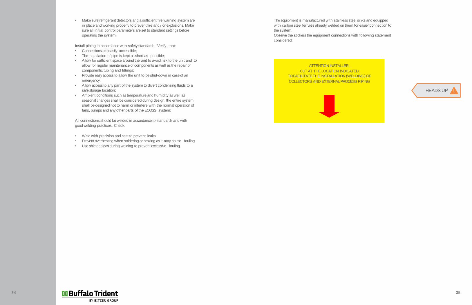
The equipment is manufactured with stainless steel sinks and equipped
with carbon steel ferrules already welded on them for easier connection to
the system.
Observe the stickers the equipment connections with following statement
considered:
ATTENTIONINSTALLER,
CUT AT THE LOCATION INDICATED
TO FACILITATE THE INSTALLATION (WELDING) OF
COLLECTORS AND EXTERNAL PROCESS PIPING
HEADS UP !
34 35

5.3.1. Installing units in parallel
Observe following notes for connecting or installing units in
Adhere to the minimum distance specifications below:
*For more information regarding the Güntner Streamer or other accessories,
please contact the technical staff of Güntner.
5.3.1.1. Trap for evaporative condensers in parallel
• Different manufacturers may have different mounting positions of coils,
thus different pressure losses may occur in the circuits after a unit
shutdown. To offset such losses of load, interconnection is shall be done
using a siphon.
• The liquid condenser output of each unit must inter-connected using a
siphon upstream of the liquid reservoir.
• Height of the liquid outlet to the center of the common header should
be at least 1500 mm;
• It is recommended to use 90 °block valves with a low pressure drop;
• Figure 6 below provides detailed instructions on handling and assembly
of upper and lower modules.
Figure 6: Installation of evaporative condensers with siphon for equalization
of pressure loss.
Description Minimum Distances
Without Güntner Streamer 3,0 m
With Güntner Streamer 2,5 m
WARNING
WARNING
The minimum recommended height of the siphon is 1500 mm. This is a
reference only; different manufactures may use different measurements
depending on equipment.HEADS UP !
WARNINGPlease consult Güntner technical support if unsure as to common header inlet
and outlet dimensions.
36 37

5.3.2. Important Notes to the installer.
5.4. Performance acceptance test
The release of refrigerant can cause injury or even death (see residual
hazards of caustic chemicals and refirgerants). Perform the following
acceptance test with an expert before operating the equipent and / or after
major changes, modifications or complete unit-exchange:
• Make sure the temperature and humidity cmply with the recommended
specifications of the ECOSS;
• Make sure the power supply is sufficient as per ECOSS specifications.
Take special precautions when interconnecting the ECOSS to the main
plant. Refer to electrical diagrams and mechanical drawings.
• Verify that vibrations and movements of the ECOSS caused by the fans
and / or the system are within guidelines. Consult the fan manufacturer
or Güntner before altering the unit;
• Perform visual inspection structural design, media and devices
(materials, connections, etc);
Make sure that no ferrus materials left by grinding or welding remain in direct
contact with stainless steel piping of paneling. Not cleaning the unit after
welding or grinding may result in contamination by carbon dioxide causing the
change in the aesthetics and durability of the equipment.
always cover unit or parts of the unit to prevent ferrus contamionation; failing to
so may void equipment warranty .
HEADS UP!
Note the labeling at the equipment!
• Check and tighten all threaded connections;
• Verify installation of connections and pipes;
• Make sure the unit is protected against mechanical damage;
• Make sure the unit is protected against inadmissible over heating and
over cooling;
• Make sure the unit is under ull control and accessible;
• Make sure the unit is installed so that it can be monitored andcontrolled
from all sides and at all times;
• Verify that you provided enough space for maintenance;
• Ensure all components such as connections, lines carrying liquids and
all electrical connections are within easy reach;
• Make sure the tubing is easily identifiable;
• Check heatexchanger for surface dirt;
• Perform function tests on the fans (speed, direction, energy, power,etc.);
• Check for damage to electrical connections of fans;
• Verify the quality of weld connections, electrical connections and all
other general connections;
• Performpressure test with test gas at a pressure of 1.1 times the MAWP
test: check the seals of the connections by using a leak detector such as
professional refrigerant detecto, a foaming agent or similar;
• Check for corrosion protection: Perform a visual inspection of all
equipment, including all bends, components and media components
that are not insulated against heat. Document and file the test results;
• Perform a test run. Observe and check the unit during the test operation,
in particular:
1. Smooth operation of the fans (noisy bearings, contactor noise,
imbalance etc);
2. Energy consumption of fans;
3. Leaks
4. Immediately report all defects to the manufacturer. Remove defects
after consultation with the manufacturer;
5. Check the unit and the interactions with the system after 48 hours of
first time operation, verify all connections and fans, document the test
results.
HEADS UP !
HEADS UP!
38 39

5.5. Test readiness before operation
• Make sure all electrical protective measures are ready to operate;
• Make sure all connections that carry refrigerants are properly
connected or welded;
• Check that all electrical connections (fans, motors, water pump,
electrical panel, etc.) were connected according to local and / or
Güntner safety standards;
• Check that all water connections of the unit are installed correctly.
5.6. Operating the ECOSS for the first time
The release of refrigerant can cause injury or even death (see reesidual
hazards with caustic chemicals or refrigerants);
Place the unit in operation only when:
• The units have been mounted and connected properly;
• After performing and accepting all preliminary tests;
• After performing a test to check the readiness of systems for operation
and all safety precautions have been taken. Follow the systems
operating instructions!
• Immediately contact the manufacturer if you want to operate the unit
under different operating conditions from those defined in the project
documents and operating manual;
• Turn on the system, including the electrical system;
• Enable the drive(s):
-Open the valves on the intake and outletside of the unit;
- Turn on the fans
- Open the water lines and enable the drainage of the water system;
-Wait until the operating point is reached. Once the operating point is
reached, the unit is ready to operate;
-See operating manual and project documents for operating point and
other system parameters,
Operating points:
1. Condensing temperature and pressure
2. Air flow volume
3. Mass flow and volume of gas and liquid line
4. Air inlet wet-bulb temperature
5. Altitude
6. Thermal capacity
7. To ensure that the operating point / paramaters are as specified and
that all adjustments are protected against unauthorized access.
HEADS UP!
5.7. Disassembling the ECOSS
The ECOSS and its components are part of the refrigeration system. The
ECOSS must be removed from service by disconnectingit from the the system
according to the instruction manual and the operation of the cooling system
installation. To do so, the fans must be turned off and unplugged from the
general electrical system and the pipe lines of the refrigerant or other media
must be disconnected from the system according to the recommendations of
the installation and operation manual:
• Turn off fans;
• Turn off the system and disconnect the electric fans;
• Close the pipes carrying the working fluid;
• Perform vacuum for 24 hours;
• Disconnect the equipment.
5.8. Unit Shutdown
NOTE! Take precaution when disconnecting the ECOSS; DO NOT EXCEED the
maximum operating pressure!
With shutdowns greater than or equal to 30 days run each fans for about 2-4
hours each month to maintain their functionality.HEADS UP !
Danger of injury and damage to property!
The release of refrigerants can cause injury or even death (see Residual hazards
with Chemicals).
Check that the maximum operating pressure may never be exceeded at any
time, even after shutdown!
DANGER !
40 41
• When the machine is operating with Ammonia (NH3) the following
recommendations should be strictly followed:
1. Danger of corrosion and dirt buildup! Ammonia as a coolant is extremely
soluble, ie it attracts moisture. Prevent moisture and dirt from entering the
unit at all times
2. Protect the unit against dust, dirt and moisture to prevent personal injury or
any damage to property.
3. With shutdowns greater than or equal to 30 days run each fans for about 2-
4 hours each month to maintain their functionality.
4. Remove the unit following Loading and Unloading instrucions in this
manual.
5. 1. Protection
-Check that the maximum operating pressure may never be exceeded at any
time, even after shutdown!
-Make sure that all electrical switched including electric heater and fans are
properly ‘locked-out’ or ‘tagged-out’.
-Special precautions must be taken during prolonged storage of the ECOSS.
Protect the unit of any physical damage or any environmental damages.
including corrosion.
-The ECOSS shall be properly evacuated of any refrigerant or oils before long
term storage.
HEADS UP!
5.9. Startup after prolonged Shut-Down.
After prolonged shutdown, make sure that all system configurations and
parameters are according the design parameters. Refer to the Instruction
and Operational Manual for special considerations; follow instrcutions
below:
• Check the readiness of the entire systems before operation. Perform allpressure tests as well as visual inspection.
• NOTE! Pressure tests for recommissioning the ECOSS should only be
conducted by appropriate means and in accordance with the technical
instructions and parameters of the equipment.
• Before Start-Up, make sure you have read and understood the
Instruction and Operational Manual(s).
5.10. Changing Refrigerants
The refrigerant of the unit should NOT be exchanged with another refrigerant
without prior written consent of the Güntner.
• Make sure that Güntner has approved and authorized any changes.
• Verify the correct refrigerant has been used according to Güntner. Ensure
that all materials used within the cooling system are compatible with the
new refrigerant.
• Make sure that MAWP (Maximum allowable Working Pressure) has not
been exceeded.
• Verify that a new test certificate may or may not be required when changing
refrigerants
• Ensure that you are in compliance with all local and national regulations.
• Ensure that all safety devices are in place and operationg before re-
commissioning.
• Make sure that all documentation as well as the unit itself shows all
information needed as to the new refrigerant.
• Full documentation, including the operating instructions and the instructions
for the entire system should be changed accordingly.
• Perform a full Acceptance Test as required by local and nationalregulations.
HEADS UP !
HEADS UP!
42 43
Emergency Response
Condensers
Evaporators /
Fluid Coolers
6.1 Safety
6.2. Emergency Measures
• Use personal protective equipment while evaluating the extend of the
leak.
• Prevent further leakage by isolating all relevant piping.
• Activate the alarm if any leakage has been detected. Ensure safety of
all persononel near or around the cooling system. Close all access
doors to prevent any refrigerant escaping to other areas.
• Activate the emergency STOP. Close all Valves;, make sure all motors
and other components are turned off to prevent further escape of the
refrigerant.
• Close valves in sections where possible, to minimize refrigerant
contamination. If possible, bleed / drain sectios of these systems. If
possible move remaing refrigerant to another section of the system.
• Cover any accumulation of refrigerant with a protective film (PE, for
example) or in a synthetic expansion foam (fire department). Minimize
any heat dissipation of the refrigerant to prevent possible steam
formation.
• Danger of personal injury and damage to property
• Possible malfunction or abnormal conditions not addressed in these
operating instructions should be reported to Güntner. Please contact your
Güntner Technical Support.
• Possible defects not addressed in these operating instructions should be
resolved by an authorized technician.
• Contact your Güntner Technical Support with any abnormal conditions of
the entire systems during operation, monitoring and maintenance.
HEADS UP !
DANGER !
44 45
Maintenance
Condensers
Evaporators /
Fluid Coolers
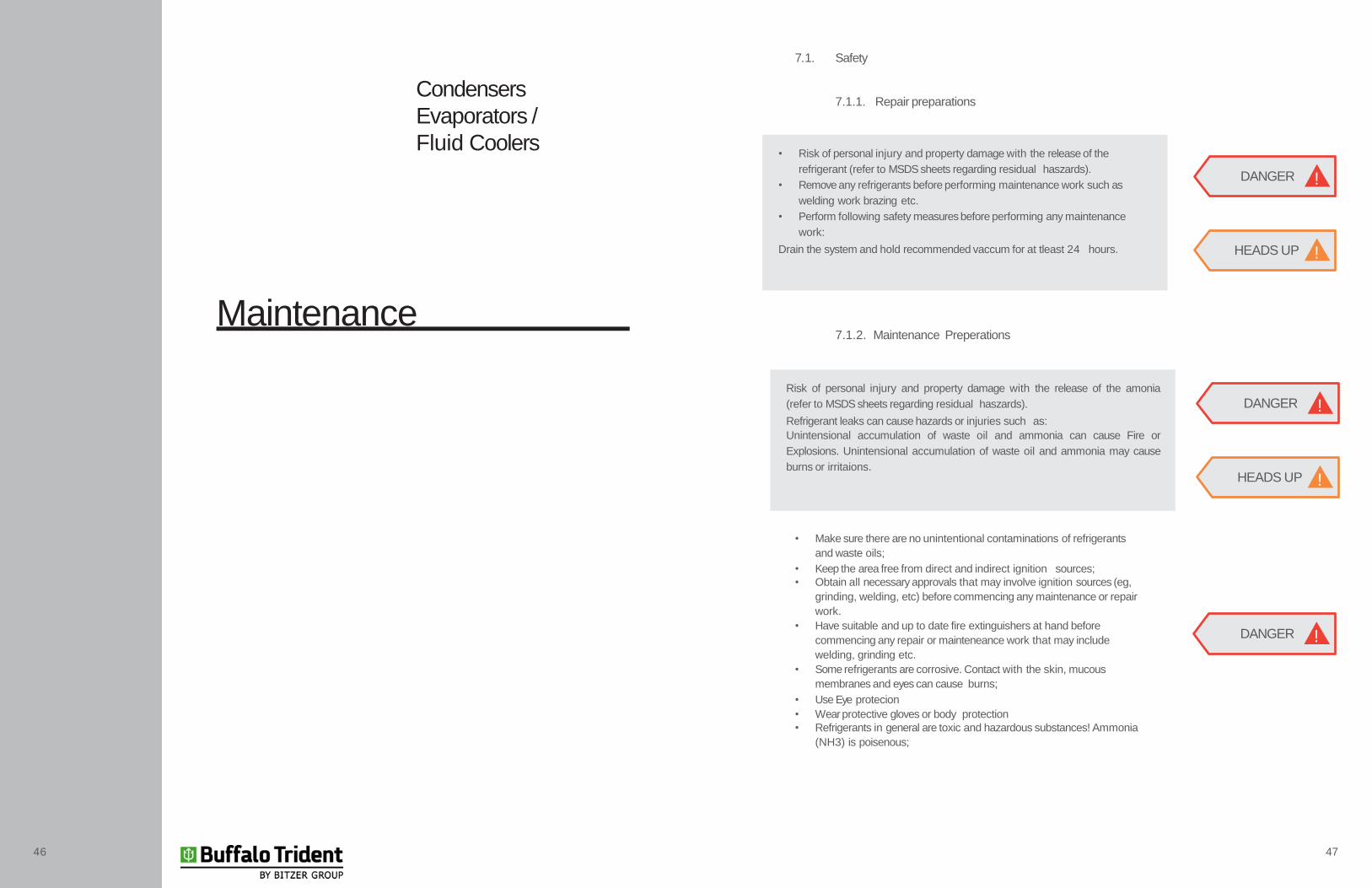
7.1. Safety
7.1.1. Repair preparations
7.1.2. Maintenance Preperations
• Make sure there are no unintentional contaminations of refrigerants
and waste oils;
• Keep the area free from direct and indirect ignition sources;
• Obtain all necessary approvals that may involve ignition sources (eg,
grinding, welding, etc) before commencing any maintenance or repair
work.
• Have suitable and up to date fire extinguishers at hand before
commencing any repair or mainteneance work that may include
welding, grinding etc.
• Some refrigerants are corrosive. Contact with the skin, mucous
membranes and eyes can cause burns;
• Use Eye protecion
• Wear protective gloves or body protection
• Refrigerants in general are toxic and hazardous substances! Ammonia
(NH3) is poisenous;
• Risk of personal injury and property damage with the release of the
refrigerant (refer to MSDS sheets regarding residual haszards).
• Remove any refrigerants before performing maintenance work such as
welding work brazing etc.
• Perform following safety measures before performing any maintenance
work:
Drain the system and hold recommended vaccum for at tleast 24 hours. HEADS UP !
DANGER !
Risk of personal injury and property damage with the release of the amonia
(refer to MSDS sheets regarding residual haszards).
Refrigerant leaks can cause hazards or injuries such as:
Unintensional accumulation of waste oil and ammonia can cause Fire or
Explosions. Unintensional accumulation of waste oil and ammonia may cause
burns or irritaions.HEADS UP !
DANGER !
DANGER !
46 47
• Use respiratory protection;
• Verify that the ECOSS has been depressurized and all refrigerant has
been evacuated before commencing maintenance or repair work.
• Verify that power has been properly disconnected; make sure that
the ECOSS has been properly ‘locked-out’ to prevent unintentional
reconnection;
• The fans and side panels are designed with hinges for easy access to
fans motors, coil and connections.
• Verify that all areas are free of foreign objects after work has been
completed to prevent damage or injury to others.
• Turn off the fans before starting maintenance work, and secure them
against unintentional closing;
• After all work has been completed, assure that no objects between the
fan-inlets and fan-oulets have been left behind.
48 49
7.1.3. Safety measures after repair work has been
completed.
Perform the following safety measures after completeing maintenance
work:
• Make sure that the switching devices, activation devices, measuring
devices, display and all safety devices are functioning properly;
• Verify that all piping connedtions have been reconnected properly and
are not leaking.
• Make sure the fans and the side hinged lids have been installed
in their original positions and protected against unintentional or
unauthorized opening;
• Verify that all piping has been properly labeled and that they are
clearly visible and legible;
• Verify corrosion protection of the components;
• Verify all electrical connections (fans and pumps) are installed properly
and functioning;
• Perform a visual acceptance test;
• Perform a torque test where required before pressure testing the unit;
7.2. Maintenance Procedures
7.2.1. Filter and Tray
• Check tray water level regualry;
• Periodiacally check and remove any dirt or debris from tray;
• Regularly drain tray water, rinse and clean with clean water to remove
salts and sediments which may have accumulated in the tray or heat
exchanger;
• Filters have to be kept in the correct position during rinsing to prevent
sediment re-entering the system;
• After rinsing the unit, filters must be removed, cleaned and replaced
before the unit can be tested with clean water.
7.2.2. Water level, supply and operation
• Regularly check the water level for optimal performance of the unit;
• Verify that all motorized valves are functioning as expected;
• Check for valve leaks and repair immediately
• Verify free movement of makeup-water float and that the valve is
closing properly;
• Ensure that the drain vent is not clogged and suitable for water
drainage.
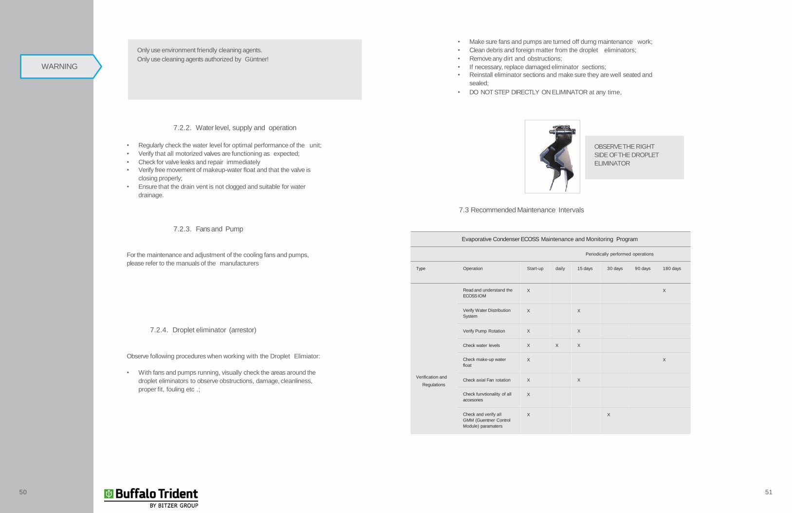
7.2.4. Droplet eliminator (arrestor)
Observe following procedures when working with the Droplet Elimiator:
• With fans and pumps running, visually check the areas around the
droplet eliminators to observe obstructions, damage, cleanliness,
proper fit, fouling etc .;
Only use environment friendly cleaning agents.
Only use cleaning agents authorized by Güntner!
WARNING
• Make sure fans and pumps are turned off durng maintenance work;
• Clean debris and foreign matter from the droplet eliminators;
• Remove any dirt and obstructions;
• If necessary, replace damaged eliminator sections;
• Reinstall eliminator sections and make sure they are well seated and
sealed;
• DO NOT STEP DIRECTLY ON ELIMINATOR at any time,
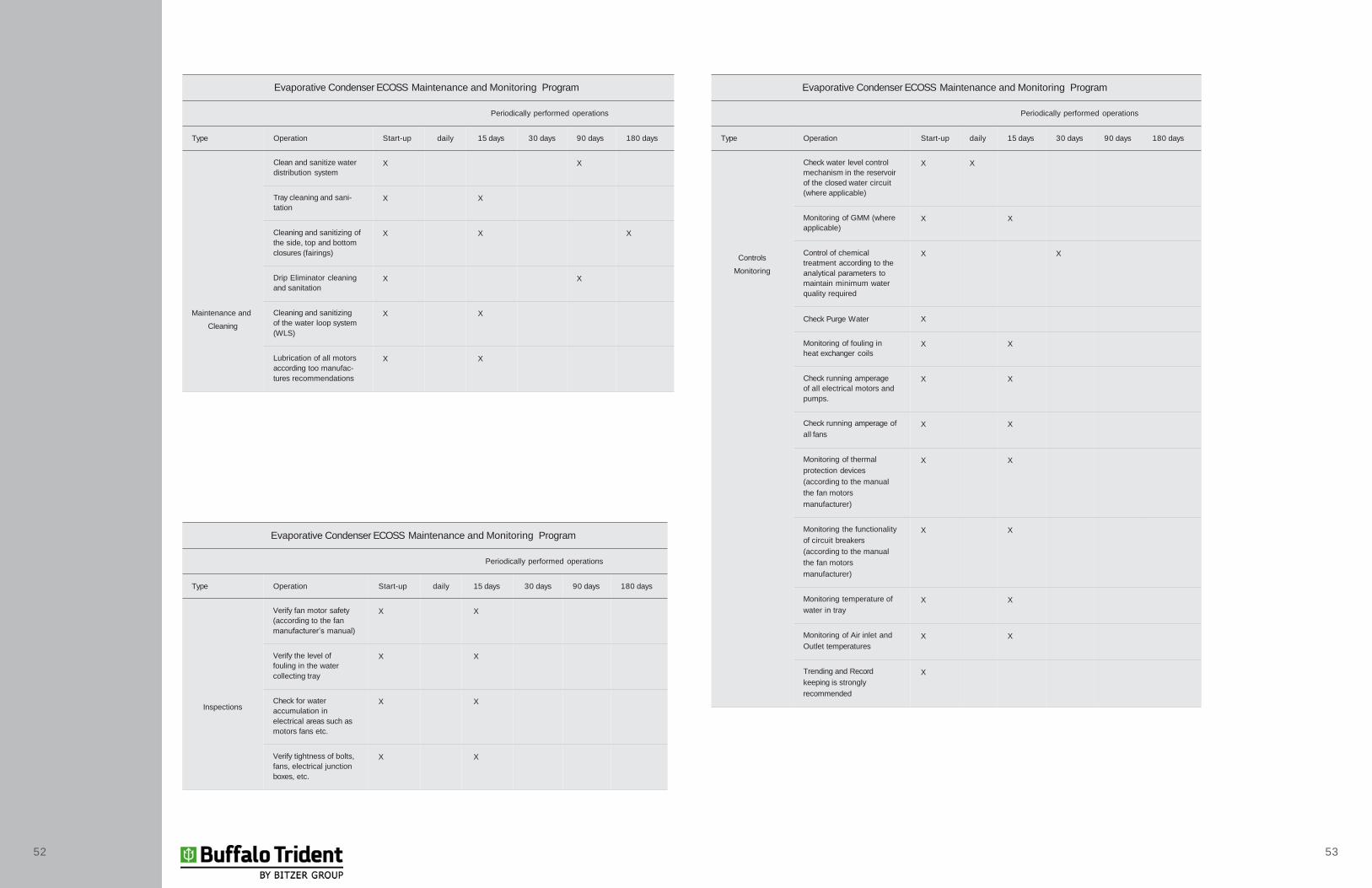
7.3 Recommended Maintenance Intervals
7.2.3. Fans and Pump
For the maintenance and adjustment of the cooling fans and pumps,
please refer to the manuals of the manufacturers
Evaporative Condenser ECOSS Maintenance and Monitoring Program
Periodically performed operations
Type Operation Start-up daily 15 days 30 days 90 days 180 days
Verification and
Regulations
Read and understand the
ECOSSIOM
X X
Verify Water Distribution
System
X X
Verify Pump Rotation X X
Check water levels X X X
Check make-up water
float
X X
Check axial Fan rotation X X
Check funvtionality of all
accesories
X
Check and verify all
GMM (Guentner Control
Module) paramaters
X X
OBSERVE THE RIGHT
SIDE OF THE DROPLET
ELIMINATOR
50 51
Evaporative Condenser ECOSS Maintenance and Monitoring Program
Periodically performed operations
Type Operation Start-up daily 15 days 30 days 90 days 180 days
Maintenance and
Cleaning
Clean and sanitize water
distribution system
X X
Tray cleaning and sani-
tation
X X
Cleaning and sanitizing of
the side, top and bottom
closures (fairings)
X X X
Drip Eliminator cleaning
and sanitation
X X
Cleaning and sanitizing
of the water loop system
(WLS)
X X
Lubrication of all motors
according too manufac-
tures recommendations
X X
52 53
Evaporative Condenser ECOSS Maintenance and Monitoring Program
Periodically performed operations
Type Operation Start-up daily 15 days 30 days 90 days 180 days
Inspections
Verify fan motor safety
(according to the fan
manufacturer’s manual)
X X
Verify the level of
fouling in the water
collecting tray
X X
Check for water
accumulation in
electrical areas such as
motors fans etc.
X X
Verify tightness of bolts,
fans, electrical junction
boxes, etc.
X X
Evaporative Condenser ECOSS Maintenance and Monitoring Program
Periodically performed operations
Type Operation Start-up daily 15 days 30 days 90 days 180 days
Controls
Monitoring
Check water level control
mechanism in the reservoir
of the closed water circuit
(where applicable)
X X
Monitoring of GMM (where
applicable)
X X
Control of chemical
treatment according to the
analytical parameters to
maintain minimum water
quality required
X X
Check Purge Water X
Monitoring of fouling in
heat exchanger coils
X X
Check running amperage
of all electrical motors and
pumps.
X X
Check running amperage of
all fans
X X
Monitoring of thermal
protection devices
(according to the manual
the fan motors
manufacturer)
X X
Monitoring the functionality
of circuit breakers
(according to the manual
the fan motors
manufacturer)
X X
Monitoring temperature of
water in tray
X X
Monitoring of Air inlet and
Outlet temperatures
X X
Trending and Record
keeping is strongly
recommended
X
7.3.1. Water distribution system – sprinkler
For the maintenance of Droplet eliminators, observe the procedure
below:
• Turn off the fans;
• Remove droplet eliminators;
• With the fans off and the pumps running, visually check the areas of
water spray and droplet eliminators to observe obstructions, damage,
cleanliness, proper fit, fouling etc .;
• Turn off the pumps;
• Remove the spray nozzle;
• Clean dirt and debris from the water distribution system;
• Make sure that the spray nozzles are clean and well suited for
operation;
• Replace damaged or missing nozzles;
• Install nozzles and make sure that they are well fitted and leak-free;
• Connect the pump and observe the distribution of water;
• Install droplet eliminators and make sure that they are well fitted and
leak-free;
• Turn on the fans.
HEADS UP!
7.4. Cleaning procedures
7.4.1. General Cleaning
• Fans, side rails and access doors are hinged for pump removal and for
easy cleaning;
• The operator shall ensure that the cleaner is environmentally friendly.
Only use cleaning agents authorized by Güntner!
• Make sure electrical connections are disconnected;
• Make sure the connections that carry the refrigerant are covered up.
7.4.2. Cleaning the coil, side panels and tray
Cleaning the coil, side panels and tray can be accomplished through:
• Cleaning with compressed air:
1. Use compressed air at a maximum pressure of 80 bar with a
minimum distance of 200 mm to remove dirt and contaminants from
coil,
2. Use compressed air at a maximum pressure of 10 bar with a minimum
distance of 200 mm to remove dirt and contaminants from side panels
and water tray.
• Hydraulic cleaning:
1. Watch out! Water and cleaning agents conduct electricity.
2. Turn off fans and water pump for cleaning with water or steam jet.
3. Watch out! Water or steam jets can damage fans, electrical
connections or other components.
4. Make sure the electrical connections, motors or other components
were not affected by water or steam. Protect them, if necessary.
5. Neutral cleaning agents should be considered if using high pressure
water or steam jet; the maximum pressure of 50 bar for coil and 10 bar
to side panels and tray shall not be exceeded; maintain a minimum
distance of 200 mm.
6. Make sure the cleaner is environmentally friendly.
7. Make sure that the chemical cleaning agents are non agressive. Rinse
the unit after the treatment.
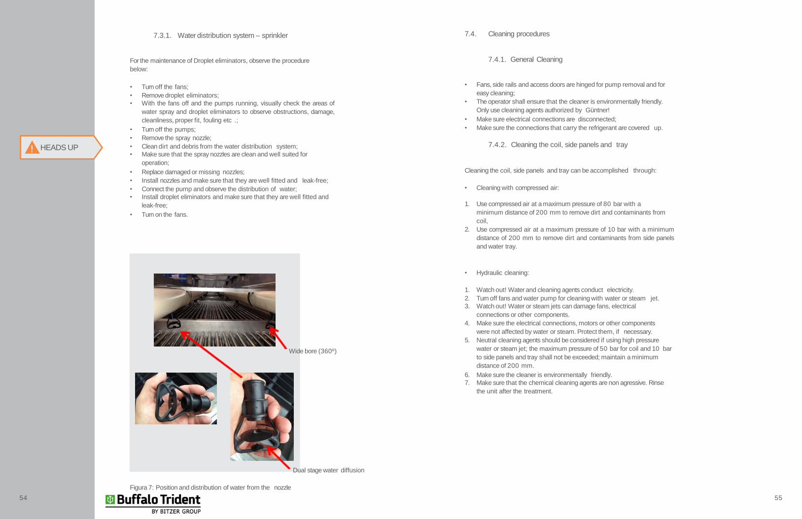
Wide bore (360º)
Dual stage water diffusion
Figura 7: Position and distribution of water from the nozzle
54 55
• Cleaning with brushes
1. Remove dust or dirt with a dry brush.
2. Use soft brushes (never use a wire brush or similar)!
7.4.3. Cleaning Fans and water pumps
For cleaning of fans and water pumps, please consult the manufacturer‘s
manuals as shown below:
7.4.4. Cleaning the coil, side panels and tray in case of
contamination by iron oxide (corrosion)
• In case of corrosion and contamination following procedures for cleaning
and surface recovery of evaporative condensers must be carried out :
ONLY USE CLEANING AGENTS APPROVED BYGÜNTNER!HEADS UP!
1. Evaluation of contamination amount present on the surface of stainless
steel. This contaminatione can be removed with a scraper or even a
knife, making sure that the blade does not damage the stainless steel
surface.
2. Sanding the surface with sandpaper is possible; choose grain size based
on the amount and grade of contamination.
3. It is recommended to start the wet sanding with # 320 sandpaper,
continuing with finer sandpaper, in sequence, # 400 and # 600 or
even # 1000; periodically change the sanding direction by 90 degrees.
Only use new sandpaper that is clean of and contamination esppecioally
abrasive particles of iron oxides. You may not use sandpaper that has
already been used for grinding carbon steel or iron.
4. After sanding clean surface with a clean, damp cloth. After this cleaning,
apply a layer of stainless steel pickling and passivation gel.
5. Apply the pickling and passivation gel or similar with a brush; follow
instructions on next page:
-The stainless steel pickling and passivation gel, or the like is a repassivation
agent for stainless steel surfaceses.
-Depending on the amount of contaminant, the reaction time of the pickling
and passivation gel shall be modified.
-Only use enough gel to cover the contamination area and for the gel to
remain wet during the exposure time.
-After gel has been applied for the recommended time, clean the surface
with plenty of clear water.
-Clean with a dry cloth to prevent staining caused by drying of the water
itself. Water comes in different hardnesses (DTS) and therefore may leave
slight stains around the water droplets itself.
- Follow guidelines below if paint stripper is used:
-The application by brush or roller should be done with rubber gloves,
goggles, boots, apron and nox type face mask.
- Only apply chemical cleaners in open and well ventilated environments.
- In case of contact with skin, wash with running water and a mild detergent.
-If eye contact occurs, seek medical attention and inform medical team of
chemical name or any other chemical indicated by the stripping agents
packaging label.
-For vertical surfaces, apply the gel moving from the bottom up, with the
brush handle facing up, so there is no runoff that may cause additional
damage to fasteners or nearby cables etc.
- For horizontal surfaces apply paint stripper gel with brush or roller.
- Avoid squeezing the brush or roller.
-Avoid contact of paint stripper with any other metallic surfaces such as
rivets, washers, screws and nuts made of aluminum or carbon steel; severe
corrosion can occur .
The presence of contamination from carbon steel (waste, grinding, sanding,
welding spatter, residues left by tools and abrasives, and the like) on the
surface of stainless steel, may lead to galvanic corrosion; this process begins
with the waste carbon steel to act as an anode (which will erode quickly) and
the stainless steel itself is the cathode (which is protected); spots may
occur due to corrosion of the carbonsteel; these spots can be iron oxide or iron
hydroxide.
These surface deposits or spots should be removed as the may cause cracks,
which, if combined with the presence of halide ions, especially chloride
(present in marine shore, from the salty air, and by the wind), can cause a
type of corrosion in stainless steels called crevice corrosion, with perforations
located on the surface of stainless steel.
HEADS UP!
56 57

Water Treatment and Purging
58 59
Condensers
Evaporators /
Fluid Coolers
8.1. Purging (Devolution of water)
Periodic or continuous purging is required to avoid an excessive concentration
of salts which increase water hardness; excessive fouling or excessive oil
accumulation may also occur. The total water lost by evaporation, drag and
purging (devolution) is replaced by makeup water. While evaporative loss
tends to concentrate impurities entrainment, the vent tends to limit this
concentration. The water circulation with normal steady loss as described
above will allow impurities to concentrate to the extent to which water has
to be added or replaced; even fresh water will have some impurities. We use
the term „cycles of concentration“ to indicate the level of impurities during
normal water circulation against the degree of impurities in the makeup
water. Thus a cycle of concentration of 5.0 indicates that the circulating
water is 5 times the concentration of impurities in the makeup water. The
characteristics of water replacement and anti-fouling as well as anti-corrosive
additives determine the cycles of allowable concentration limit to minimize
fouling or corrosion.
Recommended Cycles of Concentration can be calculated by companies
specializing in water treatment. Cycles of Concentration are based on a
thorough analysis of the characteristics of the makeup water. Based on this
analysis as well as the loss of water through evaporation, recommended
water changes as well as makeup water can be calculated.
The manufacturers of antifouling and anti-corrosion additives also formulated
biocides required to inhibit the growth of micro-organisms especially in
contaminated water and low flow rate purging.
The table on the next page indicates replacement rates based on the rates of
evaporation and purging with drag and a concentration cycle of 5.0:

2. Treatment and minimum standards of water quality
In evaporative condensers condensing of refrigerants is achieved by water
evaporation. When the water evaporates, impurities such as salt remain
present in the water. If the water is not drained (purging) from the system,
the dissolved solids concentration rapidly increases and cause fouling and /
or corrosion.
In addition to the impurities present in the feedwater, all impurities present
in the air such as biological materials are carried to the equipment and water
recirculation.
Besides the need for purging a quantity of water, a treatment program
specifically designed to cope with fouling, corrosion and biological control
must be in place. Monitoring water analysis to ensure water quality must be
implemented.
1. Biological Control
The growth of algae, slimes and other microorganisms, if not controlled, will
reduce the efficiency of the system and can contribute to the growth of
potentially harmful micro-organisms, such as Legionella,in the tray and
water recirculation system .
Thus, a treatment program designed specifically to implement biological
control should be started; regular monitoring and recording of bacteriological
contamination of water recirculation is strongly recommended. For this, a
chemical water addidive should be used; the additive must comply with
material compatibility.
8.2.2. Chemical treatment
• The chemicals must be compatible with the construction materials used
of the entire system;
• The chemicals must be specified by companies specialized in chemical
industrial wastewater treatment;
• Chemicals should be placed in the recirculating water to avoid high
localized concentrations, which can cause fouling and or corrosion. The
dosing of chemicals is allowed directly on the discharge line of the
pump;
• Placing lots of chemicals deviating from the recommended dosage
specified by manufacturer may not maintain adequate control of water
quality and is not recommended as chemical treatment;
• Monthly check of minimum water quality parameters is recommended.
See table on the next page for minimum quality parameters;
• All test results shall be recorded. If necessary, sent results to the
Güntner technical support team for analysis.
Analytical Parameter Recommended limit
pH 6,5 a 9,0
Total Alkalinity (pp CaCO3) 750
Calcium Hardness (ppm CaCO3) 500
Chlorides (ppm like CI) 100
Chlorides (ppm like NaCI) 250
Soluble Silica (ppm like SiO2) 150
Sulfates (ppm like SO4) 250
Dissolved solids (ppm) 1500
Conductivity (uS/cm) 3000
HEADS UP !
60 61

After-Sales Service Contact
Our After Sales department is specialized and committed to answer any
question, provide technical assistance and support. The range of services
includes everything from start-up to emergency repairs.
Please contact your nearest Güntner Representative Office
www.guentner.asia
NOTES
62 63

NOTES NOTES
64 65
BITZER Australia
134-136 Dunheved Circuit
St Marys NSW 2760
AUSTRALIA
www.bitzer.com.au
Condensadores a Ar
Condensadores Evaporativos / Fluidcoolers
Drycoolers
Evaporadores / Aircoolers
Máquinas de Gelo
Trocadores de Calor a Placas
Vasos de Pressão
Subje
ct to
technic
al a
mendm
ents
with
out prior
notic
e.
AP
O / M
AN
UA
L /
EC
OS
S / E
N /
JU
LY
2017