Embed Size (px)
Citation preview

Infrastructure BU / Automation / IED activity
VAMP 221 system in MCSet cubicle
Installation guide 02/2012

Installation guide: VAMP221 system in MCSet
51315625F0
2 / 15
Contents
1- INTRODUCTION .................................................................................................................3
2- POINT SENSOR (VA 1 DA-X TYPE) ................... ...............................................................3
3- POINT SENSOR LOCATION IN MCSET CUBICLE.......... .................................................4
4- CABLE COMPARTMENT ............................... ....................................................................5
4.1- Point sensor mounting ......................... .........................................................................................................5
4.2- Cable compartment arc sensor support .......... ............................................................................................6
4.3- Point sensor cabling .......................... ............................................................................................................7
5- BUSBAR COMPARTMENT .............................. ..................................................................8
5.1- Point sensor mounting ......................... .........................................................................................................8
5.2- Busbar compartment arc sensor roof cover ...... .........................................................................................9
5.3- Point sensor cabling .......................... ..........................................................................................................10
6- CIRCUIT BREAKER COMPARTMENT ..................... .......................................................11
6.1- Point sensor mounting and cabling ............. ..............................................................................................11
7- LOW VOLTAGE COMPARTMENT......................... ..........................................................12
7.1- VAMP 221 central unit mounting (ref : V221-A3A AA)................................................ ...............................12
7.2- VAM I/O units Din rail mounting ............... ..................................................................................................13
7.3- VAM I/O units flush mounting .................. ...................................................................................................14
ANNEX : REFERENCE DOCUMENTS........................ .........................................................15
Revisions
Modification (cut-out of flush mounting unit) February 16th, 2012 Bruno WATTIEZ
Additional drawing (arc sensor support and roof cover)
January 23rd, 2012 Bruno WATTIEZ
First issue January 9th, 2012 Bruno WATTIEZ
Type of revision date Written by

Installation guide: VAMP221system in MCSet
51314495F0
3 / 15
Point sensor VA 1 DA-x (surface)
1- Introduction The aim of this guide is to indicate the appropriate installation rules for the VAMP Arc Flash protection system with point sensors (Central unit + I/O units + point sensors) in MCSet Medium Voltage cubicles. This guide does not take anything away from VAMP technical documents. It is aimed at providing further explanations and additional information on the installation rules that already exist in : “Operation and configuration instructions – Technic al description” Ref : V221/EN M/A016 “VAMP arc flash protection testing manual” Ref VARC TEST/EN M/A001 This document is available through Pl@net intranet site. These installation rules contribute to guarantee the correct operation and performance levels of VAMP Arc Flash protection system in MCSet Medium Voltage cubicles.
2- Point sensor (VA 1 DA-x type) VA 1 DA-x : x means 6 or 20 meters shielded cable to be specified in the order Due to the wide detection range of the sensors and the light reflection inside the switchgear, the mounting position is not critical. Note : If point sensors are used in open compartments (such as Busbar compartment), there should be a point sensor approximately every 5 meters .

Installation guide: VAMP221 system in MCSet
51315625F0
4 / 15
3- Point sensor location in MCSet cubicle The point sensors are located to supervise the cable compartment, the bus bar compartment and the circuit-breaker compartment.
Busbar compartment point sensor VA 1 DA-x type
Circuit Breaker compartment point sensor VA 1 DA-x type
Cable compartment point sensor VA 1 DA-x type
Point sensor VA 1 DA-x (surface)
MCSet cubicle

Installation guide: VAMP221system in MCSet
51314495F0
5 / 15
4- Cable compartment 4.1- Point sensor mounting
Cable compartment point sensor VA 1 DA-x type
Cable compartment at the back of MCSet cubicle

Installation guide: VAMP221 system in MCSet
51315625F0
6 / 15
4.2- Cable compartment arc sensor support

Installation guide: VAMP221system in MCSet
51314495F0
7 / 15
4.3- Point sensor cabling Point sensor conductors run in the installation structure of the MCSet Medium Voltage cubicle (cable trunking, metal ducts, etc….)
Connected to VAM I/O unit located in the Low Voltage compartment
Running of point sensor conductors
Cable compartment at the back of MCSet cubicle
Compartment s at the front of MCSet cubicle
Arc sensor support

Installation guide: VAMP221 system in MCSet
51315625F0
8 / 15
5- Busbar compartment 5.1- Point sensor mounting
Busbar compartment point sensor VA 1 DA-x type
Busbar compartment at the back of MCSet cubicle

Installation guide: VAMP221system in MCSet
51314495F0
9 / 15
5.2- Busbar compartment arc sensor roof cover

Installation guide: VAMP221 system in MCSet
51315625F0
10 / 15
5.3- Point sensor cabling Point sensor conductors run in the installation structure of the MCSet Medium Voltage cubicle (cable trunking, metal ducts, etc….).
Running of point sensor conductors
Connected to VAM I/O unit located in the Low Voltage compartment
Top of MCSet cubicle
Arc sensor roof cover

Installation guide: VAMP221system in MCSet
51314495F0
11 / 15
6- Circuit Breaker compartment 6.1- Point sensor mounting and cabling
Circuit Breaker compartment point sensor VA 1 DA-x type
Connected to VAM I/O unit located in the Low Voltage compartment
Circuit breaker compartment with gaz channel from the back of MCSet cubicle
Gaz channel from the top of MCSet cubicle

Installation guide: VAMP221 system in MCSet
51315625F0
12 / 15
7- Low voltage compartment 7.1- VAMP 221 central unit mounting (ref : V221-A3A AA)
VAMP 221 Panel mounting

Installation guide: VAMP221system in MCSet
51314495F0
13 / 15
7.2- VAM I/O units Din rail mounting VAM12LSE point sensor I/O unit (same mounting for VAM10LSE point sensor I/O unit, VAM4CSE current I/O unit and VAMP4RSE trip multiplier relay)
VAM I/O unit Din rail mounting
Installation guide: VAMP221 system in MCSet
51315625F0
14 / 15
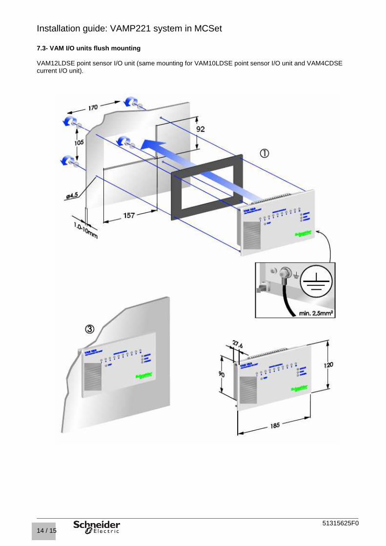
7.3- VAM I/O units flush mounting VAM12LDSE point sensor I/O unit (same mounting for VAM10LDSE point sensor I/O unit and VAM4CDSE current I/O unit).

Installation guide: VAMP221system in MCSet
51314495F0
15 / 15
ANNEX : Reference documents V221/EN M/A016.pdf Operation and configuration instructions – Technical description SMMCARC001.pdf Mounting and Commissioning Instructions NRJED111072EN_VAMP 221 BR.pdf VAMP221 system commercial brochure VARCTEST/EN M/A001.pdf VAMP arc flash protection testing manual