Embed Size (px)
Citation preview
KM-1 /v.1/2017 1
KOTRBATÝ VYTÁPĚNÍ - VZDUCHOTECHNIKA - REGULACE
AWARDED WITH PRESTIGE EUROPEAN PRICE FOR QUALITY
INFRARED GAS FIRED TUBE HEATER
KM 10 - 1; KM 15 - 1; KM 22,5 - 1
KM 30 - 1; KM 36 - 1; KM 45 – 1
Technical
instructions 1015 , AO 202
Safety instructions
Construction of heaters
Technical data
Assembly
Operation, maintenance
Service, control
16, certifikát č. E - 30 - 00510 – 03 – rev.2
KOTRBATÝ V.M.Z. spol. s r.o. Design & Bussiness Sluzeb 5/256, 108 00 Prague 10, Czech Republic, tel.: +420 245 005 921, email: [email protected]
Manufacture & service
Sdružená 1788, 393 01 Pelhřimov, tel.: +420 564 571 520, email: [email protected]

KOTRBATÝ VYTÁPĚNÍ -VZDUCHOTECHNIKA-REGULACE
Infrared gasfired tube heater KM
KM-1 /v.1/2017 2
Page
Table of contents : 1. Introduction 3
2. Symbols used in documentation 3
3. Safety instructions 3
3.1 Assembly instructions 4
3.2 Instructions for operator and operation staff 4
3.3 Instructions for inspections and revisions 4
3.4 Repairs. Spare parts 5
3.5 Impermissible manner of operation 5
3.6 Evaluation of residual risks 5
4. Type, description 6
5. Intended use 6
6. Electrical wiring diagram 7
7. Function of infrared heater 8
8. Construction of infrared heater 8
9. Basic dimensions of inidvidual infrared heaters 10
10. Technical data 11
11. Heater’s suspension 12
11.1 Minimum suspension height 12
11.2 Safety distances 13
12. Gas connection 14
13. Scope of delivery 14
14. Heater’s assembly 15
15. Flue gas venting 15
16. Combustion air intake 16
17. Infrared heater as a C - type appliance 17
18. Maximum length of flue gas venting and combustion air inlet 18
19. Transportation. Storage 18
20. Disposal of packaging and product after service life 19
21. Inspections and revisions 19
22. Spare parts 20
23. Operation 21
24. Local operation rules 22
25. Contacts 23
26. Notifications 24
Separate annexes:
Annex A Heaters‘ documentation
(nameplate, service report, warranty list, test protocol)
Annex B1 Assembly guide for tube radiant heaters KM-1 with length 5 meters
Annex B2 Assembly guide for tube radiant heaters KM-1 with length 7 up to 20
meters

KOTRBATÝ VYTÁPĚNÍ -VZDUCHOTECHNIKA-REGULACE
Tube infrared heater KM
KM-1 /v.1/2017 3
1. Introduction
Main principle
Infrared gas fired tube heaters works on a
principle of closed system ("I" shaped tube).
These heaters achieve needed performance by
gas combustion in atmospheric burners, from
where the flue gases are routed into the
radiant tubes provided with reflexive covers.
Surface temperature of the tubes moves in the
range between 180 – 580 °C. Radial flue gas
ventilator, located at the end of the I-tube,
secures sufficient movement of hot air in the
tube and concurrently removes flue gases.
These heaters are ideal also for lower halls
and for the halls with dusty operation,
because it is possible to supply the
combustion air from outside. Also, it is suited,
with very high efficiency, for wholespace
heating. Infrared heaters‘ heating system is, in
comparison with warm-air or convectional
heating systems very economical.
Attributes of infrared radiation:
Infrared radiation spreads
straightforwardly, so the heaters could be
targeted
Infrared radiation changes into heat in the
absorbent body
Radiation intensity lowers by square of
the distance between radiation source and
absorbent body
Infrared radiation moves through the air
without transfering the heat
Main advantages of the infrared heaters:
Investment savings in comparison to
“classical” heating systems
Savings on operating costs
Operating readiness
Possibility of local heating according to
the requirements
Do not whirl dust
Easy operation
Easy assembly
Low noise
Possibility of regulation
2. Symbols used in documentation
Thorough adherence of the
guidelines needed
Prompt warning to use safety
and personal protective tools in
any case of manipulation with
gas fired infrared heater KM
Electric shock hazard, possible
risk of a fire during assembly or
manipulation with gas fired
infrared heater KM
NOTICE! Important instructions or
warning of possible
consequences in case these
instructions will not be followed
3. Safety instructions
This documentation includes basic guidelines
for assembly, operation and service of gas
fired infrared heaters, type “KM”,
manufacturer KOTRBATÝ. Also included are
basic technical information, dimensions of
each heater and description of each part of the
heater.
KOTRBATÝ VYTÁPĚNÍ -VZDUCHOTECHNIKA-REGULACE
Tube infrared heater KM
KM-1 /v.1/2017 4
NOTICE! It is absolutely necessary that
the assembly workers, same
as the operational staff and
operator have read this
documentation thoroughly
before assembly and
commissioning of the heater.
This documentation must always be
accessible at the place, where the device
is operated. Beside these instructions, it is
necessary to follow all applicable regulations,
ordinances and technical standards relating to
gas and electrical appliance, as gas fired
infrared heater belongs to both groups. During
assembly, operation and maintenance the staff
have to follow all safety rules, including use
of personal protective tools.
3.1. Assembly instructions
Installation, assembly and repair work on the
gas consumption appliances can be carried
out only by qualified workers of authorized
organisation. Assembly has to be carried out
according to manufacturer’s instructions as
follows, with respect to applicable regulations
and technical standards, including safety
rules.
Assembled appliance can be
commissioned into the
operation only by a service
technician of Kotrbatý
company, or a technician of
approved company, with valid
certification for infrared
heaters commissioning issued
by Kotrbatý.
3.2. Instructions for operator and
operation staff
Operator is obliged to authorize in writing
those workers, who will be operating gas fired
infrared heaters. These workers must be
physically and mentally able to do the work,
must be over 18 years old and must be trained
by service technician of Kotrbatý for
operating the heaters. Responsibilities of
operator and operation workers arising from
applicable regulations, ordinances and
technical standards are complemented with
requirements given in this documentation.
Operator is also obliged to inform all workers
working in the area heated with infrared
heaters of the necessity of reporting anything
unusual related to the operation of heater to
the operation worker or authorized personnel
of the operator.
NOTICE! Any interventions into the
appliance are forbidden, in case
of need call service of
manufacturer.
3.3. Instructions for inspections and
revisions
All gas fired infrared heaters KM is subject to
regular inspections and revisions. Appliance
inspections can be performed only by
operation worker (see article 3.2) or
authorized person in case of following safety
rules and instructions set by relevant
regulation and this documentation.
Appliance revision can be performed only by
authorized personnel – revision technicians,
following applicable regulations and technical
standard. During electrical revision it is
necessary to follow instructions given in this
documentation to prevent damage of control
KOTRBATÝ VYTÁPĚNÍ -VZDUCHOTECHNIKA-REGULACE
Tube infrared heater KM
KM-1 /v.1/2017 5
automatics.
3.4. Repairs. Spare parts
Repairs of gas fired infrared heaters KM can
be performed only by Kotrbatý service
technicians or companies authorized by
Kotrbatý. It is forbidden to assemble any
spare parts into the appliance. Any defective
parts have to be changed for original parts by
service technician.
It is absolutely necessary to
close gas ball valve before the
heater and disconnect the
appliance power supply –
electric shock hazard!!!
NOTICE! Service technician is approved
to maintain operations on the
heater only if he is certified to
do so by technical supervision
authorities and was trained !!
3.5. Impermissible manner of operation
Safe operation of gas fired infrared heater can
be guaranteed only if their use is in
accordance with regulations, technical
standards and instructions given in this
documentation.
Given limit values of gas
overpressure at the appliance
entry (5 kPa) and nominal
voltage must not be exceeded.
3.6. Evaluation of residual risks
Even though the gas fired infrared heaters are
manufactured in accordance with technical
standards and must be operated so, there are
some residual risks, about which the operator
has to be informed :
- Possible burn through of the radiant tube
in the distance of approx. 1,5 m from the
burner, due high temperature of the
flame. Depends on environment quality,
duration of the usage or gas pressure
fluctuation. In case of finding burn
through, switch off the heater and call
service technician to change the radiant
tube
High temperature of radiant tubes and
stainless cover – possible burning. If any
activity have to be done near the heaters,
the appliance should be turned off and at
least one hour prior. It is important to
inform workers, who will be operating
near the heater, about the appliance and
secure it from accidentally switching on.
For suspension of the infrared heaters the
surface-treated chains or other appropriate
suspensions have to be used, to prevent
corrosion, possible tearing and fall of the
heater.
NOTICE! Not following safety rules and
instructions may result into very
serious endangerment of
personnel, buildings, appliance
itself or environment. In case of
gas leak all the appropriate
safety measures have to be done
immediately!
WARNING!! Before
installation, check if local
conditions of fuel distribution,
overpressure and appliance
settings are compatible! This
appliance has to be installed in
accordance with applicable
regulations and its usage is

KOTRBATÝ VYTÁPĚNÍ -VZDUCHOTECHNIKA-REGULACE
Tube infrared heater KM
KM-1 /v.1/2017 6
allowed only in well ventilated
area. It is necessary to read
the manual before assembly
and operation of the heater!
4. Type, description
Gas fired infrared tube heater KM-1 is open
fuel appliance (type B), which takes
combustion air from the area where it is
installed, and the flue gases are routed
through the flue gas duct system to the
external environment. In the operations,
where the combustion air has to be supplied
from the external environment (for ex.
polluted air area, overpressure or negative
pressure area) the heater is closed fuel
appliance, type C, where the combustion air is
supplied by air duct system from the external
environment and the flue gases are routed
through the flue gas duct system to the
external environment. Infrared heater
category is II2H3B/P, II2E3B/P, I2H, I2E, fuel
natural gas or propane butane.
5. Intended use
Infrared heater is designed for heating of large
area objects, industrial halls, production
spaces, warehouses, sport halls etc. Features
and appliance protection given by its
construction have to be in accordance to
established external influences in the area
where the infrared heater is used.
Infrared heater is designed
for standard areas, and must
not be installed in area with
fire or explosion risk etc. Flue
gases from the heater must be
routed away from the
installation area (into external
environment).
Appliances with atmospherical burners in
type B must not be installed in rooms, where
the negative pressure can be created by the
ventilators of air vent appliances! Insufficient
supply of combustion air causes incomplete
combustion. Because of that, it is necessary to
secure sufficient air supply resulting from
infraheaters need, hygienic regulations for
given building or characteristics of operation
carried out in the heated area without
considering necessary ammount of air for
heating. Air supply must be reflected in the
design of heating and in the design of heaters
for given area.
KOTRBATÝ VYTÁPĚNÍ -VZDUCHOTECHNIKA-REGULACE
Tube infrared heater KM
KM-1 /v.1/2017 7
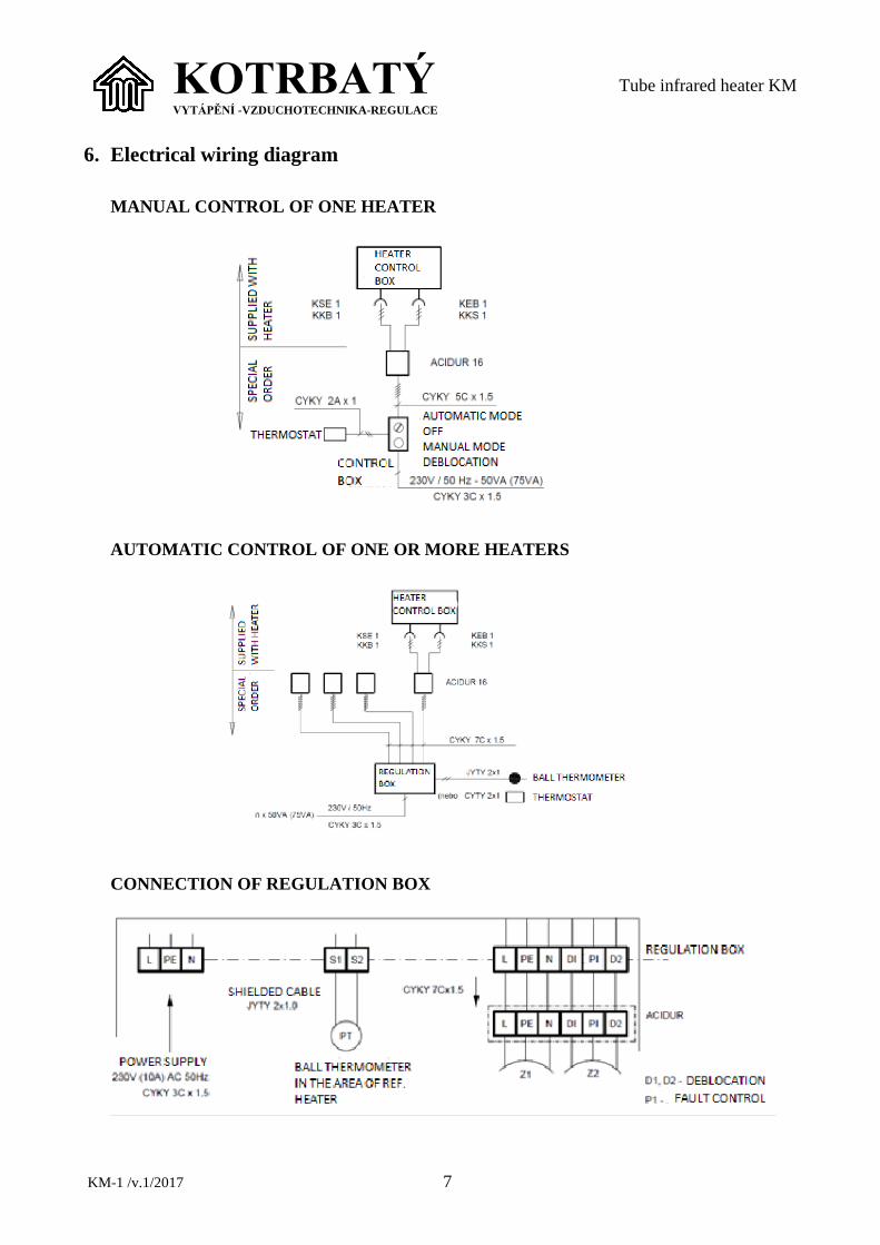
6. Electrical wiring diagram
MANUAL CONTROL OF ONE HEATER
AUTOMATIC CONTROL OF ONE OR MORE HEATERS
CONNECTION OF REGULATION BOX

KOTRBATÝ VYTÁPĚNÍ -VZDUCHOTECHNIKA-REGULACE
Tube infrared heater KM
KM-1 /v.1/2017 8
7. Function of infrared heater
Infrared heater KM-1 is gas fired heater with
deep cover. Heat supply to the space is carried
out with radiaton of heat tubes. Deep reflector
from stainless polished sheet metal directs
radiation heat flow into the area beneath the
heater.
Independent units, connected to the radiation
tubes, are burner box with automatics, gas
supply entry, supply pipe for combustion air
and ventilator box with ventilator and
connection for flue gas outlet. Heater
automatics regulates gas pressure ahead of
nozzle. It allows constant gas supply into the
mixing aspirator of burner.
Infrared heater can be operated manually or
automaticaly (see the wiring diagram). When
the electricity is brought from the control box
to the control automatics in the burner box,
valves of gas fitting opens and on the ignition
electrode emerges ignition spark. In case of
the fuel blend ignition, ionisation electrode
detects flame, starting cycle stops and control
automatics holds gas fitting valves opened –
heater is in operation. If the fuel blend is not
ignited, the flame is lost or in a case of power
loss during starting cycle (5 sec.), gas fitting
valves are closed and the heater is outaged
(„faulty“). For restart it is necessary to
deblocate the heater by pushing deblocation
button on the control box.
8. Construction of infrared heater
In the figure no. 1 and no. 2 is displayed
complete infrared heater consisting of
radiation tubes conected into I-shape, which
are attached to the suspension by clips. Baffle
plate is retracted into the radiation tube
(furnace). If needed those tubes are connected
with clutch. All of these is covered by deep
stainless reflector, estblished in suspensions.
If the infrared heater is insulated, on the
external surface of reflector is fastened
insulation. Independent units are heater
burner box with automatics (a torch body, gas
pressure regulator with electromagnetic valve,
gas and air manostat and control automatics)
and ventilator box with ventilator.

KOTRBATÝ VYTÁPĚNÍ -VZDUCHOTECHNIKA-REGULACE
Tube infrared heater KM
KM-1 /v.1/2017 9
Infrared heater up to 6 m length
Fig.1 Construction of an infrared herater with length up to 6 m
Infrared heater from 6 m length
Fig.2 Construction of an infrared herater with length higher than 6 m
KOTRBATÝ VYTÁPĚNÍ -VZDUCHOTECHNIKA-REGULACE
Tube infrared heater KM
KM-1 /v.1/2017 10
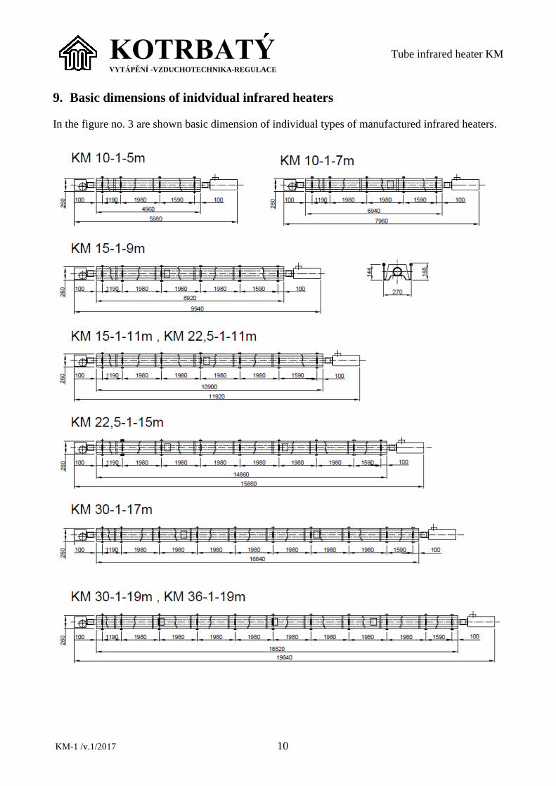
9. Basic dimensions of inidvidual infrared heaters
In the figure no. 3 are shown basic dimension of individual types of manufactured infrared heaters.

KOTRBATÝ VYTÁPĚNÍ -VZDUCHOTECHNIKA-REGULACE
Tube infrared heater KM
KM-1 /v.1/2017 11
Fig.3 Construction variants of tube infrared heaters KM-1
10. Technical data
Infrared heater marking
Nominal length (m)
Thermal output (kW)
Furnace shape: 1 – single tube
Reflector: N – non insulated
I - insulated
Nominal thermal output:
10; 15; 22,5; 30; 36; 45 (kW)
Heater type: Tube (KM)
Tables 1, 2 and 3 gives basic technical data, connection dimensions and operational conditions of
individual heaters.
Nominal gas overpressure at the input – G20 natural gas kPa 2,0-5,0
- G30(G31)propane-butane kPa 3,0-5,0
Gas overpressure at burner - G20 natural gas kPa 1,6
- G30(G31)propane-butane kPa 2,3
Gas connection into the heater - G 3/4“
Degree of electrical protection - IP 40
Nominal voltage V/Hz 230/50
Nominal electrical input (KM10, KM15, KM22,5, KM30, KM36) W 50
Nominal electrical input (KM45) W 75
Max. noise at 1 m dB (A) 55
Flue gas chimney - diameter mm 100
Combustion air input - diameter mm 100
Tab.1

KOTRBATÝ VYTÁPĚNÍ -VZDUCHOTECHNIKA-REGULACE
Tube infrared heater KM
KM-1 /v.1/2017 12
KM 10-1 KM 15-1 KM 22,5-1
Thermal output kW 5,0 10,0 12,0 14,0 17,0 18,0 23,0
Nominal thermal input kW 5,3 10,7 13,7 15,2 18,6 19,8 25,7
Gas consumption: m3/h 0,53 1,07 1,37 1,52 1,86 1,98 2,57
- G20 natural gas
- G30(G31) propane-butane kg/h 0,56 0,82 1,05 1,16 1,42 1,51 1,97
Nominal length mm 5 000 7 000 9 000 11 000 11 000 15 000
Total length mm 4 960 6 960 8 920 10 900 10 900 14 860
Suspensions - 4 x 2 5 x 2 6 x 2 7 x 2 7 x 2 9 x 2
Weight - Non-insulated
reflector
kg 65 85 100 120 125 160
Weight - Insulated reflector kg 70 92 110 130 135 175
Nozzle diameter – G20 mm 1,8 2,5 2,8 3,0 3,5 3,6 3,8
Position of air-gauge -G20 - 1 1 3 4 6 5 7
Nozzle diameter – G30 mm 1,5 1,8 2,0 2,1 2,2 2,3 2,7
Possition of air-stop -G30 - 2 2 3 3 4 5 6
Tab.2
KM 30-1 KM 36-1 KM 45-1
Thermal output kW 24,0 28,0 30,0 36,0 45,0
Nominal thermal input kW 27,6 31,5 34,1 39,2 48,7
Gas consumption: m3/h 2,76 3,15 3,41 3,92 4,87
- G20 natural gas
- G30(G31) propane-butane kg/h 2,11 2,41 2,49 3,01 3,74
Nominal length mm 17 000 19 000 18 820 19 820
Total length mm 16 840 18 820 19 840 20 900
Suspensions - 10 x 2 11 x 2 11 x 2 11 x 2
Weight - Non-insulated
reflector
kg 175 195 200 220
Weight – Insulated reflector kg 195 215 220 240
Nozzle diameter – G20 mm 4,0 4,3 4,5 4,7 5,3
Position of air-gauge -G20 - 8 8 10 11 8
Nozzle diameter – G30 mm 2,8 3,1 3,3 3,5 3,7
Position of air-stop -G30 - 6 7 9 10 7
Tab.3
11. Heater’s suspension
Suspension is done, depending on local
conditions, with surface treated chains of
relevant carrying capacity, depends on local
conditions (see weight of heaters).
NOTICE! Chains are attached to tube
suspensions with M8 screws,
because of that it has to have
eyes of diameter 8,5 mm -12
mm.
11.1. Minimum suspension height
Table 4 and picture 4 gives minimum
suspension height of the heater in hygienic
terms for a standing person. For a sitting
person can be adequately lowered.
Type of heater Output
(kW)
A (m)
0° 15° 30°
KM 10-1 10 4,2 4,0 4,0
KM 15-1 17 4,3 4,0 4,0
KM 22,5-1 23 4,5 4,3 4,0
KM 30-1 30 4,7 4,5 4,2
KM 36-1 36 4,7 4,5 4,2
KM 45-1 45 4,9 4,7 4,5
Tab.4

KOTRBATÝ VYTÁPĚNÍ -VZDUCHOTECHNIKA-REGULACE
Tube infrared heater KM
KM-1 /v.1/2017 13
Fig. 4
11.2. Safety distances
Radiating tubes must be
arranged in a way to guarantee,
that surface temperature of
flammable materials in core
radiation area does not exceed
85 °C.
This is true, if the distance of flammable
materials in core radiation area is higher than
2000 mm (fig. 5). In the picture is also given
distance value x from the ceiling structure.
Fig. 5
Horizontal suspension : x = 800 mm - flue
gas output through the chimney to external
environment.
Oblique suspension : x = 1200 mm - flue gas
output through the chimney to external
environment.
Safe distance of flammable
construction from the non
insulated parts of chimney is
1000 mm.
Electrical distribution must be
lead in a way, to avoid
exceeding its surface
temperature 35 °C (inside the
core radiation area minimum
distance of 1500 mm from the
heater, outside of the area
minimum 900 mm).
If it is not possible to comply to the given
distances, it is necessary to protect flammable
constructions and cable distribution with
reflexive metal sheets (fig. 6), at best from
polished stainless metal sheet. Between metal
sheet and construction, there must be a air gap

KOTRBATÝ VYTÁPĚNÍ -VZDUCHOTECHNIKA-REGULACE
Tube infrared heater KM
KM-1 /v.1/2017 14
30 mm at minimum. In the core radiation area
and in the distance up to 1,5 m above the
heater there must not be any gas piping!
Precise placement of the heaters in terms of
fire safety must be included in every design,
which addresses a specific local situation.
NOTICE! Special cases or ambiguities is
necessary to consult with
Kotrbatý company and Fire
departement authorities.
If there is a crane runway below the heaters, it
is necessary to equip it with reflexive metal
sheet (see above) in width of core radiation
area + 100 mm to all sides. Crane then moves
permanently with this cover, which serves as
a barrier against radiation for the crane
construction and crane control cables
overheating. If there are other lifting
appliances in the area, it is necessary to heet
on all safety rules to prevent damages on
appliance or operation personnel health
threats.
Fig. 6
NOTICE! Radiation tube temperature
ranges from 560 – 180 °C
(from burner to ventilator)!
12. Gas connection
Connect heaters by attested gas hose for gas
appliances connection, union nut G3/4“ (to
the heater valve), external thread R3/4“ (to the
gas pipeline), hose 1m long. Gas supply pipe
must be fitted with manual shut-off valve
G3/4“ – internal thread! Connection of the
hose must follow hose manufacturer manual
and in accordance to heater dilatation during
operation.
Connection hose lifespan is
given in its manufacturers
manual!
13. Scope of delivery
Heater is delivered unfolded
Delivery includes :
Radiation furnace with suspensions and
baffle plates
Unfolded stainless reflector with
connection material
Burner box, ventilator box, connection gas
hose
Other elements, as control box (switchboard),
parts of chimney, parts of combustion air feed
etc. are part of special order.
14. Heater‘s assembly
Heater assembly manual, assembly rules and
warnings are parts of separate appendixes,
which are integral parts of this technical
documentation.
List of appendixes:
Appendix B1 Infrared heater assembly
manual KM 1 - 5 m long

KOTRBATÝ VYTÁPĚNÍ -VZDUCHOTECHNIKA-REGULACE
Tube infrared heater KM
KM-1 /v.1/2017 15
Appendix B2 Infrared heater assembly
manual KM 1 7 - 20 m long
15. Flue gas venting
Flue gas venting has to be considered in the
design. It is necessary to follow all the realted
valid standards and regulations in area of
operation (ie. in EU: EN 1443, EN 15287-
1+A1, EN 15287-2)
It is necessary to keep safe
distance from flammable
objects ! (see below)
NOTICE!
It is strictrly recommended (in some areas
even mandatory) that the operator will have
carried out regular cleaning, inspection and
revision of the chimney from organisation
approved by KOTRBATÝ. This way the
lifetime of the devices can be significantly
prolonged.
Flue gas venting can be led by chimney
through slanting wall of a skylight or a roof,
or by chimney through the peripheral wall.
Chimney must be controlable, cleaneble or
must be easily demountable.
Connection of individual parts of chimney
must be made of certified elements for
overpressure operation. To eliminate risk of
ejection, we recomend to ensure connections
firmly with rivets or self-tapping screws.
Keep a safe distance from flammable
materials (flue gas temparature can rise up to
220 °C, as well as surface temperature of the
chimney).
In the figure 7 there is shown typical chimney
through the roof O-V, in the figure 8 typical
chimney through the peripheral wall O-H.
Fig.7 Typical chimney set trough the roof
Basic set O-V (fig.7) Item
1 – Meidingers head D100 202.007
2 – Chimney body D100/180 202.009
3 – Water covering D180 202.020
4 - Sheeting D180 202.019
5 - T-piece D100/45° 202.049
6 – Condensation closure D100 202.050
7 - flexo tube Inox D100 202.064
8 – Two piece socket D100 202.034
9 - Two piece socket D180 202.036
Fig.8 Typical chimney set trough the wall
Basic set O-H (fig.8) Item
1 – Meidinger head D100 202.008
2 – Straight pipe D100 202.047
3 – both side shrunk-on D100 202.030
4 – flexo tube Inox D100 202.064
5 – one piece socket D100 202.031

KOTRBATÝ VYTÁPĚNÍ -VZDUCHOTECHNIKA-REGULACE
Tube infrared heater KM
KM-1 /v.1/2017 16
In a reasonable cases, it is possible to connect
two heaters on conjoint chimney. It is
necessary to secure simultaneus operation of
both heaters, to keep sufficient exhaust and
prevent flue gas leak.
NOTICE! Finished chimney must obtain
identification label (EN 1443),
placed at accesible part of the
chimney.
16. Combustion air intake
Combustion air inlet, if the operation
conditions of heated area permits, can be led
in through the roof construction, or skylight
construction (vertical type solution P-V in
fig. 9) or through the facede of the building
(horizontal type solution in fig. 10) or based
on individual design. All parts of the feed
must be firmly connected.
Fig.9 Typical air intake through the roof
Basic set P-V (fig.9) Item
1 – cover of inlet pipeline D100 202.029
2 – straight pipe D100 202.047
3 – rubber pipe sealing collar Ø76-152 202.067
4 – flex pipeline Semivac D100 165.051
5 – quick fitting stripe 155.010
6 - Two piece socket D100 202.034
Fig.10 Typical air intake through the wall
Basic set P-H (fig.10) Item
1 – end pipe D100 202.017
2 - flex pipeline Semivac D100 165.051
3 - both side shrunk-on D100 202.030
4 - quick fitting stripe 155.010
5 - one piece socket D100 202.031
17. Infrared heater as a type C
appliance
Type C appliance represents appliances where
the combustion circle is closed towards the
ambient area. Heater in that case features
concurrentely chimney for flue gas venting
and combustion air inlet for the outdoor air
(typical solutoion see figures 7, 8, 9, 10).
NOTICE! Finished chimney must obtain
identification label (EN 1443),
placed at accesible part of the
chimney..
KOTRBATÝ VYTÁPĚNÍ -VZDUCHOTECHNIKA-REGULACE
Tube infrared heater KM
KM-1 /v.1/2017 17
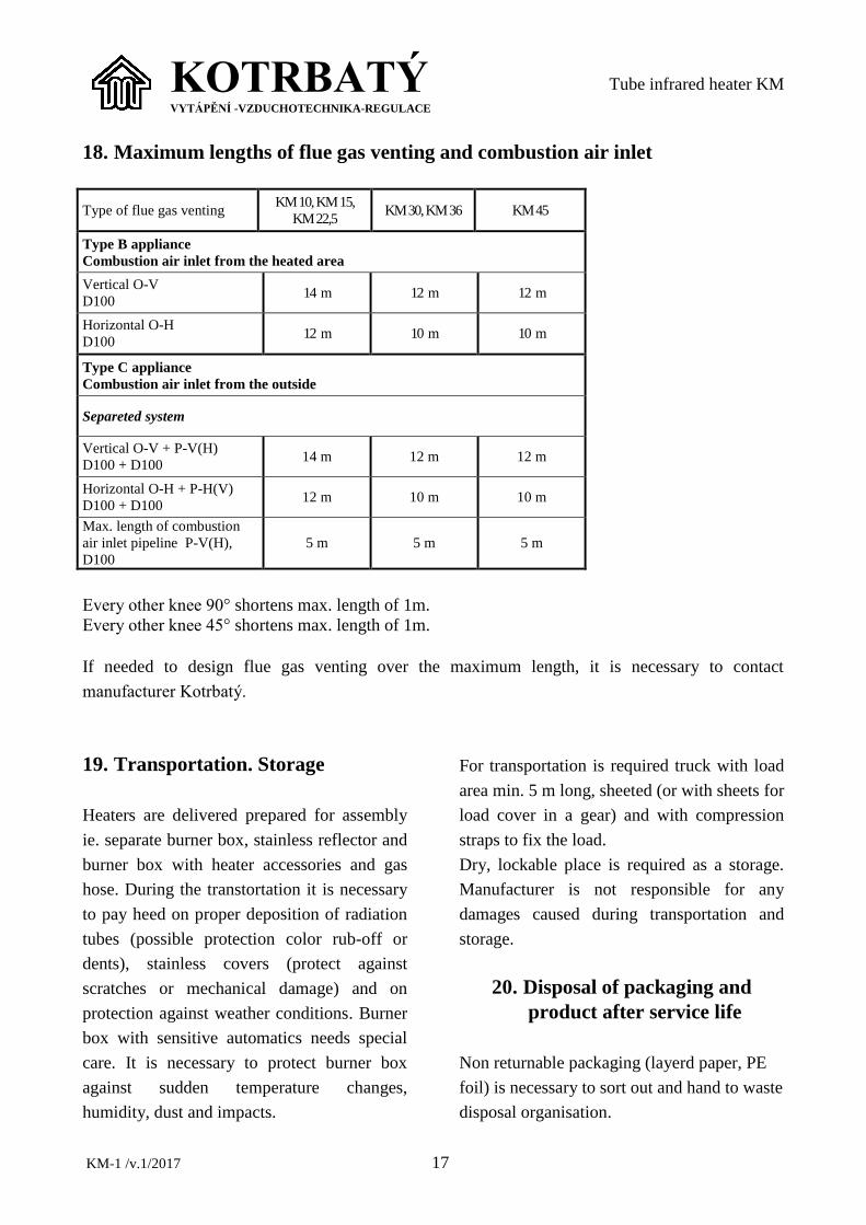
18. Maximum lengths of flue gas venting and combustion air inlet
Type of flue gas venting KM 10, KM 15,
KM 22,5 KM 30, KM 36 KM 45
Type B appliance
Combustion air inlet from the heated area
Vertical O-V
D100 14 m 12 m 12 m
Horizontal O-H
D100 12 m 10 m 10 m
Type C appliance
Combustion air inlet from the outside
Separeted system
Vertical O-V + P-V(H)
D100 + D100 14 m 12 m 12 m
Horizontal O-H + P-H(V)
D100 + D100 12 m 10 m 10 m
Max. length of combustion
air inlet pipeline P-V(H),
D100
5 m 5 m 5 m
Every other knee 90° shortens max. length of 1m.
Every other knee 45° shortens max. length of 1m.
If needed to design flue gas venting over the maximum length, it is necessary to contact
manufacturer Kotrbatý.
19. Transportation. Storage
Heaters are delivered prepared for assembly
ie. separate burner box, stainless reflector and
burner box with heater accessories and gas
hose. During the transtortation it is necessary
to pay heed on proper deposition of radiation
tubes (possible protection color rub-off or
dents), stainless covers (protect against
scratches or mechanical damage) and on
protection against weather conditions. Burner
box with sensitive automatics needs special
care. It is necessary to protect burner box
against sudden temperature changes,
humidity, dust and impacts.
For transportation is required truck with load
area min. 5 m long, sheeted (or with sheets for
load cover in a gear) and with compression
straps to fix the load.
Dry, lockable place is required as a storage.
Manufacturer is not responsible for any
damages caused during transportation and
storage.
20. Disposal of packaging and
product after service life
Non returnable packaging (layerd paper, PE
foil) is necessary to sort out and hand to waste
disposal organisation.

KOTRBATÝ VYTÁPĚNÍ -VZDUCHOTECHNIKA-REGULACE
Tube infrared heater KM
KM-1 /v.1/2017 18
After passing service life (or
dismantling) of the heater, it is
necessary to disconnect the
heater from the electric supply
and secure it by authorized
person, also it is necessary to
close gas valve ahead of the
heater, disconnect conection
hose and seal the ball valve!!
After end of heaters service life it is
neccessary to disassembly it and hand it to the
waste collection service while:
Furnace is made from steel tubes
Reflectors (covers) are made from
stainless metal sheet 17 040
We recommend to hand burner box with
accessories to Kotrbatý, Pelhřimov, Czech
Republic.
Used packaging catalogue no.
Layerd paper 15 01 01
Polyethylene foil 15 01 02
21. Inspections and revisions
Appliance inspections has to be
done at least once in a year. We
recommend to have two
inspections – before and after
heating season.
Inspections must be made by qualified
personnel (gas + electro qualification) from
authorised organisation. We recommend to
have inspections done by persontel of
Kotrbatý company or personel certified by
Kotrbatý.
Ongoing inspections has to be done by
personnel appointed by operator to heater
operation during whole year (especially
during heating season see art. 21)
In case of more often inspections, its dates
specifies in local operating rules, depending
on technical condition and operational
experiences. Air quality control and leak
detection is recommended during the
inspections.
Revisions are held according to
revisions schedule at least once
in three years, if other
regulations or authorities do not
povide otherwise. Gas
connection hose is a subject to
same revision as gas
distribution!!
Electro revisions must be done according to
EN 60079-17 ed.4:2014 and related.
CAUTION! Electronical device –
Automatics (E.F.D.503) – is installed in the
burner box. It is not possible to gauge
Resistance – insulation 500 V! Substitute
measuring method must be used. Revision
technician is not authorized to disconnect
heater from the gas hose during the revision,
because it will be taken as an intervention in
the gas appliance!!
NOTICE!
It essential to follow safety
rules during activities listed
below!!!
Moreover, it is work in heights!
Workers must have certificate
of yearly regular training and
medical examination!!!
Activities listed below bea risk
of electric shock and burn (from
flue gases or heaters body). It
KOTRBATÝ VYTÁPĚNÍ -VZDUCHOTECHNIKA-REGULACE
Tube infrared heater KM
KM-1 /v.1/2017 19
has to be performed only by
trained personnel with
qualification listed in appendix
B!!!
As a part of heater inspection and
maintenance it is necessary:
To check tightness of all gas joints from ball
valve ahead of heater to the nozzle in burner
box. We recommend to use personal gas
detector.
To check gas hose (if it is not damaged or
tensioned)
To check intactness of radiation tubes (if it is
not burned)
To check suspension of the heater (state of
chains and screws, anchoring into the
supporting construction
Wipe off dust from the burner box and
stainless cover
Wipe ignition and ionization electrode, check
connecting of these electrodes to the cables
Start the heater and measure gas pressure on
the nozzle – if the value does not accords, set
the pressure on prescribed value.
Check the tightness of the measuring probes
at gas valve. We recommend to use personal
gas detector
Check controls of heater
(function of control box, thermostate and
switchgear)
After inspection and
maintenance it is necessary to
start heater repeatedly!!!
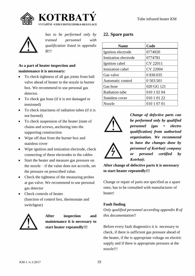
22. Spare parts
Name Code
Ignition electrode 0774920
Ionization electrode 0774781
Ignition cabel CV 22011
Ionization cabel CV 22004
Gas valve 0 830.035
Automatic control 0 503.501
Gas hose 020 GG 121
Radiation tube 010 1 02 04
Stainless cover 010 1 01 22
Nozzle 010 1 07 01
Change of defective parts can
be performed only by qualified
personnel (gas + electro
qualification) from authorised
organisation. We recommend
to have the changes done by
personnel of Kotrbatý company
or personel certified by
Kotrbatý.
After change of defective parts it is necessary
to start heater repeatedly!!!
Change or repair of parts not specified as a spare
ones, has to be consulted with manufacturer of
heater!
Fault finding
Only qualified personnel according appendix B of
this documentation!!
Before every fault diagnostics it is necessary to
check, if there is sufficient gas pressure ahead of
the heater, if the is appropriate voltage on electric
supply and if there is appropriate pressure at the
nozzle!!!

KOTRBATÝ VYTÁPĚNÍ -VZDUCHOTECHNIKA-REGULACE
Tube infrared heater KM
KM-1 /v.1/2017 20
Fault Cause
Heater starts up,
goes off after while
- non funcitonal ionisation
electrode
- faulty ionisation cabel
- control automatics fault
Heater does not start,
but ignition electrode
sparks
- control automatics fault
- fault gas valve
Heater does not start,
and ignition electrode
does not spark
- fault air manostate
- fault ventilator
- fault ignition electrode
- fault ignition cabel
- control automatics fault
23. Operation
For operation, inspections and revisions,
operational logbook and operation of gas
appliances see valid local standards and
regulations. Operation of the heater can be
done only by personnel authorized by
operator, who were provably introduced to its
operation, control and regulation system,
safety rules and local operating rules.
Instructions for control and regulation system
are given by installing organisation.
Any interventions to the
appliance are forbidden!!! (If
needed, call service
organisation)
Maintenance obligation
Each worker operating heater must know:
Local operating rules
Safety rules
Control system (regulation)
Location of gas, water and electricity
main closure
Location of separete manual gas closures
ahead of each heater
Worker is obligated :
- Visually check smooth running of the
heater after the ignition
Green indicator = operation
Red indicator = fault
Execute two more starts using deblocation
if the flame extinguish or heater does not
start up (red indicator lights)
Once in a three weeks perform visual
check of heaters – check first meter of
radiation tube for „reddening“ (side near
to the flame), flaking or burn-throughs,
check burner box for damages (curled to
side, ripped front side), check if the heater
is hanged horizontally, if the furnace parts
are well connected, if the flue gas outlet is
undamaged, if the stainless reflector does
not went out of its initial fitting etc.
check gas connection hose if it is not
tensioned (see hose manufacturers
instructions for assembly)
if any fault or damage was found,
immediately make safety measures and
call service organisation
Never operate damaged
heater!!! Gas appliance
operator is obliged to perform
safety measures after finding
of gas leak to prevent safety
hazard for people and
property!!!
In case of heater shutdown for a period longer
than 1 month, shut off main gas closure on the
route to the heaters or gas valve ahead of the
heater!
After every maintenance it is necessary to
turn the heater on!!

KOTRBATÝ VYTÁPĚNÍ -VZDUCHOTECHNIKA-REGULACE
Tube infrared heater KM
KM-1 /v.1/2017 21
Turning heater on and off
Heater can be operate only by personnel
fulfilling requirements from article 22. During
training of the personnel by service technician
is trained person acquainted with installed
control system.
Control can be manual or automatic
(temperature, time or combined regulation)
with possible manual turning on and off.
If the heater do not start up or turn off shortly
after the ignition, operation personnel
deblocates heater by using deblocation button
of the relevant heater on control box.
If the heater does not turn on even after
several deblocations (max. 5x), operation
personnel should:
turn off relevant heater at the control box
close gas ball valve ahead of the heater
Work above 1,5 m from the
floor is classified as a work in
heights – worker who is
closing the gas valve at the
heater level must have
according training and
regular medical check!
On the switch of relevant heater puts a
label „Out of service- do not turn on!“
Informs service technician (see art. 24)
Operation personnel must not interfere into
the control box!!!
24. Local operation rules
Operator of gas infrared heater KM is obliged
to write local operation rules :
a) Basic requirements :
Title list
Table of contents
Address and telephone number of gas
company holding emergency, fire
department, emergency medical services,
elektricity company, technical service of
Kotrbatý
appliance basic technical values
short characteristic of used gas
b) Other requirements :
Basic scheme of gas part
isntructions for regulation and operation
of heaters
Art.12.1. of this documentation, setting
operation personnel obligations
Instructions for security and other devices
(if installed)
Instruction for leak search including terms
Terms of air control
Type of operation (permanent, occasional
etc.), names and contacts of operation
personnel
Operation instructions
Instructions for decommisioning
Instructions for case of faul or an accident
Terms of inspections and revisions
First aid instructions
special requirements according to local
conditions
Before begining of any works,
possibly changing external
effects in heated area (for ex.
Work with paints, adhesives,
wood etc.), it is necessary to
decommision heaters for the
period. Setting back into
operation can be done just
after the parameters of

KOTRBATÝ VYTÁPĚNÍ -VZDUCHOTECHNIKA-REGULACE
Tube infrared heater KM
KM-1 /v.1/2017 22
surrounding environment are
in original state.
If the change of external effects will be
permanent, it is necessary to provide new
determination of effects in the area by
authorized person, who decide, it the heaters
can be operated. (see art. 5 of this
documentation).
25. Contacts
KOTRBATÝ V.M.Z. spol. s r.o.
Sales and design
Služeb 5/256
108 00 Praha 10
Czech Republic
tel.: +420 245 005 921
email: [email protected]
Manufacture, service
Sdružená 1788
393 01 Pelhřimov
Czech Republic
tel.: +420 564 571 520
email: [email protected]

KOTRBATÝ VYTÁPĚNÍ -VZDUCHOTECHNIKA-REGULACE
Tube infrared heater KM
KM-1 /v.1/2017 23
26. Notifications
ATTENTION !
GAS APPLIANCE – a product specified under the
provisions of Czech Rep. Act No. 22/1997 Coll.
and Governmental Decree No. 177/1997 Coll.
Assembly of gas fired infrared heater must be done
strictly by the enclosed assembly manual!!! This appliance must be installed in accordance with valid
guidelines and its use is allowed only in well vented area. Before
assembly and commisioning it is necessary to read the manuals.
Power cords end in electrical ACIDUR box with the wreath cca 1
m from the burner!
Before commisioning of the heater:
Provide revisions of gas and electricity (copies give to service
technician)
Fill gas piping with gas and perform air venting
In case of any problems, contact manufacturer:
+420 245 005 921

KOTRBATÝ VYTÁPĚNÍ -VZDUCHOTECHNIKA-REGULACE
Tube infrared heater KM
KM-1 /v.1/2017 24
Separete annex A
Appliance documentation
INFRARED HEATERS‘ NAMEPLATE
1015 , AO 202 VÝROBNĚ MONTÁŽNÍ ZÁVOD, SDRUŽENÁ 1788 XX
393 01 PELHŘIMOV, CZ
Infrared heater, type KM -
Serial number -
Nominal output kW
Nominal input kW
Fuel type -
Fuel consumption m3/h
Connection overpressure-min. mbar
Connection overpressure -max. mbar
Pressure on nozzle mbar
Country of appliance destination -
Appliance category - II2H3B/P
Class NOx - 2
Total appliance weight kg ………………
Voltage V 230
Power input W ………………
Frequency Hz 50
Degree of protection - IP 40
Year of manufacture (XX at CE ) -

KOTRBATÝ VYTÁPĚNÍ -VZDUCHOTECHNIKA-REGULACE
Tmavý infračervený zářič KM
KM-1 /v.1/2017 25
SERVICE LIST OF
INFRARED HEATER KM
Serial
number Performed activity Date Signature
Commisioning and adjusting
KOTRBATÝ VYTÁPĚNÍ -VZDUCHOTECHNIKA-REGULACE
Tmavý infračervený zářič KM
KM-1 /v.1/2017 26
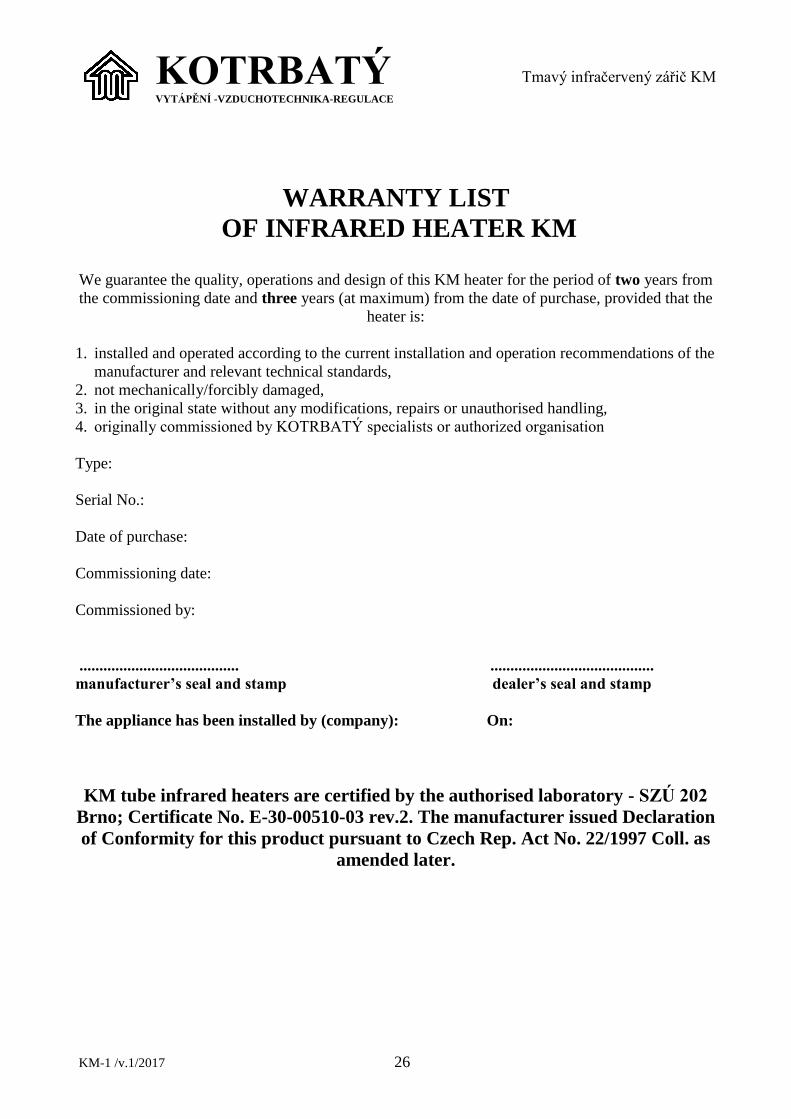
WARRANTY LIST
OF INFRARED HEATER KM
We guarantee the quality, operations and design of this KM heater for the period of two years from
the commissioning date and three years (at maximum) from the date of purchase, provided that the
heater is:
1. installed and operated according to the current installation and operation recommendations of the
manufacturer and relevant technical standards,
2. not mechanically/forcibly damaged,
3. in the original state without any modifications, repairs or unauthorised handling,
4. originally commissioned by KOTRBATÝ specialists or authorized organisation
Type:
Serial No.:
Date of purchase:
Commissioning date:
Commissioned by:
........................................ .........................................
manufacturer’s seal and stamp dealer’s seal and stamp
The appliance has been installed by (company): On:
KM tube infrared heaters are certified by the authorised laboratory - SZÚ 202
Brno; Certificate No. E-30-00510-03 rev.2. The manufacturer issued Declaration
of Conformity for this product pursuant to Czech Rep. Act No. 22/1997 Coll. as
amended later.

KM-1 /v.1/2017 27
KOTRBATÝ V.M.Z. s.r.o.
address: Sdružená 1788 tel.,fax: 564 571 520-2
TEST PROTOCOL
Gas appliance – infrared heater KM
Type of infrared heater: KM Serial number:
1. Test of completeness and correct assembly of the burner box
Checked according to internal regulation KP 06/01 qualifies
2. Functional test
Completely checked according to internal regulation KP 06/01 qualifies
3. Test of tightness of the heater burner gas system
- Tightness test of welded joints qualifies
- Tightness test of screw joints qualifies
- Tightness test of gas probes qualifies
Tightness tested with gas detector according to internal regulation KP 06/01
Overall results of the tests: qualifies (device is capable of putting into operation)
Tests conducted:
Pelhřimov, date .................................
Stamp, signature