Embed Size (px)
Citation preview
Informix Extended Parallel Server 8.3


Table of Contents
Introduction
Benefits of Informix Extended Parallel Server 8.3
Informix Extended Parallel Server 8.3 Architectural Overview
5 Request Manager
5 Query Optimizer
6 Metadata Manager
6 Scheduler
6 A True Shared-Nothing Database Architecture
Optimized for Data Warehouse/Decision Support Processing
12 Simplify Data Access and Analysis Through Star Schema
13 Very Large Data Storage Capacity
13 Fast Data Access Through Efficient Indexing Methods
21 Enhanced Join Methods
25 Enhanced SQL Extensions
Database Administration and Management
27 Query Management
28 Parallel Loader
29 Alter Fragment
Conclusion


1
Data warehousing has become a critical
component in management’s quest to turn
transactional data into decision-making
information. Unlike traditional on-line
transaction processing (OLTP) systems that
automate day-to-day operations, a data
warehouse provides an environment in
which an organization can evaluate and
analyze enterprise data over time. It allows a
business to reconstruct history and accurately
compare data from different time periods,
providing the information necessary for
strategic planning and decision making.
Because data warehouse operations are typ-
ically complex, analytical, and involve a large
amount of data, businesses are increasingly
deploying shared-nothing hardware archi-
tectures such as massively parallel (MPP)
systems and clusters of symmetrical processing
(SMP) systems to ensure performance and
scalability. These systems are made up of
independent uniprocessors or SMP (referred
to as nodes) that are connected through a
high-speed, point-to-point, interconnected
network. Shared-nothing hardware architec-
tures are ideal for running data-intensive
operations because nodes are not bounded
by a common system bus or operating
software. They are well-suited for data
warehouse environments—characterized by
exponential growth in database size and
processing—because they are easily expand-
able and configurable.
Database management systems are equally
important in the development and deployment
of data warehouses. Applications that access
data warehouses—also known as decision-
support (DSS) applications—typically involve
scans of entire tables, manipulation of data,
multiple joins, and creation of temporary
tables. These operations are pushing the
limits of traditional database management
systems in the areas of performance, scala-
bility, and availability. Additionally, many
database management systems simply cannot
take full advantage of shared-nothing
hardware architectures.
Informix® Extended Parallel Server™ 8.3 addresses
the complex needs of data warehouses and
DSS applications. Designed specifically to
handle the demands of very large databases
(VLDBs), Informix Extended Parallel Server 8.3
offers a shared-nothing database engine,
complementing the shared-nothing hardware
systems. This highly optimized data engine
utilizes all available hardware resources
including CPU, memory, disks, and more,
delivering mainframe-caliber scalability,
manageability, and availability, while
requiring minimal operating system overhead.
In addition to a shared-nothing database
engine, Informix Extended Parallel Server 8.3
offers a complete set of features to further
enhance the performance of decision support
queries. These features include enhanced SQL
extensions and join methods to improve the
execution of large decision-support queries,
new indexing methods to accelerate access
to data, and a graphical administration
environment to ease management of large
volumes of data.
Introduction

True Linear Scalability
Informix Extended Parallel Server 8.3 is
designed to meet the needs of users as their
requirements grow, in data warehouse size,
numbers of users, volume of transactions,
and complexity of analyses. Its unique
“shared nothing” design ensures true linear
scalability, allowing businesses to make
the most efficient use of available hardware
resources to deliver the highest level of
performance for all types of data ware-
house operations.
Fastest Ad-Hoc Query Performance
Understanding that management needs timely
information to make key decisions about
their businesses, Informix Extended Parallel
Server 8.3 is specifically designed to provide
an optimized environment maximized for
all types of decision-support operations.
Informix Extended Parallel Server 8.3 offers
a host of features to speed the execution of
complex, analytical queries, with performance
up to 100 times faster than on the same
hardware. Resource-management utilities
ensure optimum distribution of system
resources—including CPU, memory, and
disks—and increase processing efficiency
to further enhance query performance. The
result is query response time measured in
minutes rather than hours, and hours rather
than days, ensuring that decision-makers get
fast access to the accurate information they
need to keep their businesses competitive.
High Availability and “On the Fly” Reconfiguration
A highly available database environment is
important, given that DSS queries are
becoming more complex and analytical,
and data volumes involved in the queries are
increasing at an exponential rate. Informix
Extended Parallel Server 8.3 has the ability to
be rapidly reconfigured so that if a processor
fails, another one can be switched to take
over its workload.
Informix Extended Parallel Server 8.3 also
allows processors to be added at times of
peak load, simply by restarting the database.
There is no time-consuming re-initialization
required. This maximizes hardware utilization
by eliminating the need for permanently con-
figured systems (sometimes referred to as hot
replacement) that are idle most of the time.
Flexibility for Meeting Dynamic Needs
A flexible database environment is important
in supporting the dynamic needs of a data
warehouse. To efficiently provide timely
information for strategic planning, applications
must be designed around business needs,
rather than being limited by technology and
database design. Administrators typically
cannot predict the type, quantity, and com-
plexity of queries being submitted, so the
database must provide the flexibility to sup-
port the changing processing requirements.
2
Benefits of Informix Extended Parallel Server 8.3
3
Because different DSS operations have distinct
processing requirements for achieving optimum
performance, Informix Extended Parallel
Server 8.3 offers multiple implementation
options on such key features as schema
design, data fragmentation, skew manage-
ment, indexing, table joins, and resource
management. These options offer the flexibility
to choose the best execution path to obtain
the fastest response time and allow Informix
Extended Parallel Server 8.3 to efficiently
handle different processing loads without
performance degradation.
Hardware Independence
Informix Extended Parallel Server 8.3 is
available on a wide variety of UNIX® systems
and processing architectures. It takes full
advantage of SMP, uniprocessor, NUMA,
cluster and MPP systems, both 32 and 64
bit. Informix Extended Parallel Server 8.3
maximizes the return on users’ hardware
investment by capitalizing on the strengths
of these different architectures.

Figure 1
Each node runs an instance
of the database server called
the co-server.
Informix Extended Parallel Server 8.3 is the
only technology designed from the ground
up to address the complexities of very large
volume, ad-hoc decision support query
processing for many users.
Like the hardware that it supports, Informix
Extended Parallel Server 8.3 takes a shared-
nothing approach to managing data, thereby
greatly minimizing operating system overhead
and reducing network I/O. To achieve this
level of independence, each node runs its
own instance of Informix Extended Parallel
Server 8.3 that consists of basic services for
managing its own logging, recovery, locking,
and buffer management. This instance of the
database is called a co-server.
Each co-server “owns” a set of disks and
the partitions of the database that reside on
these disks. A co-server typically has physical
accessibility to other disks owned by other
co-servers for failover purposes, but in normal
operation, each co-server only accesses disks
that it owns. (See Figure 1.)
To optimize performance, the system catalog
containing information about the way in
which the data is distributed can be cached
across the nodes.
Additionally, smaller, frequently accessed
tables can be replicated across the nodes to
further enhance performance.
Although multiple instances of the Informix
Extended Parallel Server 8.3 are running,
all of the co-servers cooperate to provide
the image of a single, large server. This
single-system image is provided to both
general database users and also to system
and database administrators.
Different clients can connect to different co-
servers. The co-server that the client connects
to is called the connection co-server. The
connection co-server determines if a client
request can be satisfied with data that resides
on the co-server alone, or whether it requires
data that resides on other co-servers. If the
co-server requires data that resides on another
co-server, it interacts and coordinate activities
with participating co-servers. For example,
client A connects to co-server 1. After deter-
mining that it does not have the necessary
data to complete the request, co-server 1,
the connection co-server, calls co-server 2,
which becomes the participating co-server
to co-server 1, to complete the request.
Informix Extended Parallel Server 8.3 Architectural Overview
4
Co-server 1 Co-server 2 Co-server 3
Log 1Disk1 & 2 Log 2
Disk3 & 4 Log 3
Disk5 & 6
5
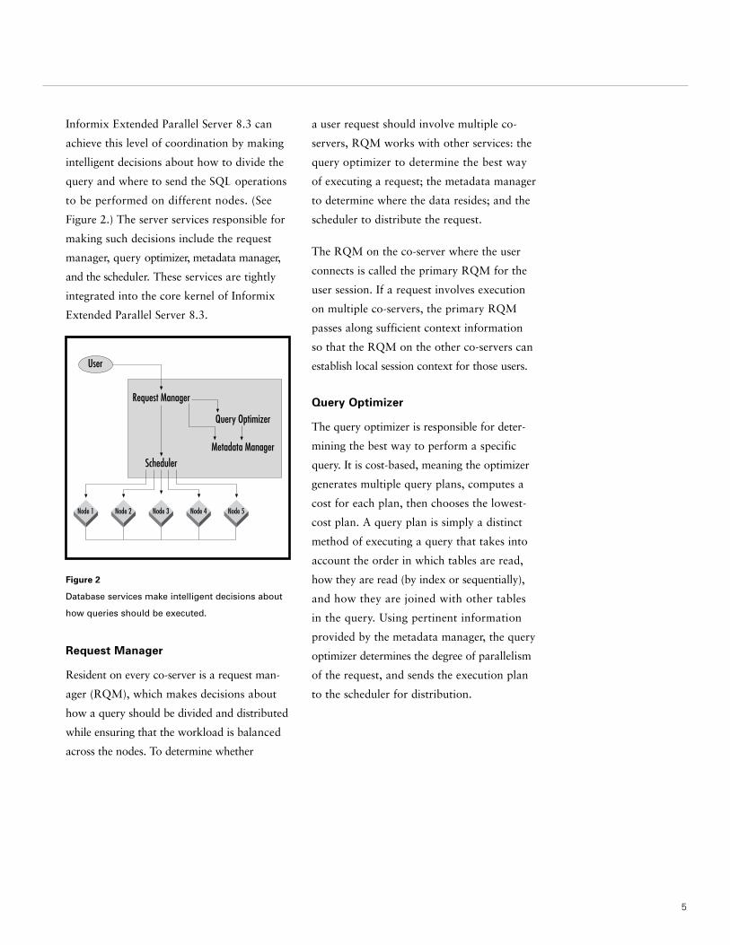
Informix Extended Parallel Server 8.3 can
achieve this level of coordination by making
intelligent decisions about how to divide the
query and where to send the SQL operations
to be performed on different nodes. (See
Figure 2.) The server services responsible for
making such decisions include the request
manager, query optimizer, metadata manager,
and the scheduler. These services are tightly
integrated into the core kernel of Informix
Extended Parallel Server 8.3.
Figure 2
Database services make intelligent decisions about
how queries should be executed.
Request Manager
Resident on every co-server is a request man-
ager (RQM), which makes decisions about
how a query should be divided and distributed
while ensuring that the workload is balanced
across the nodes. To determine whether
a user request should involve multiple co-
servers, RQM works with other services: the
query optimizer to determine the best way
of executing a request; the metadata manager
to determine where the data resides; and the
scheduler to distribute the request.
The RQM on the co-server where the user
connects is called the primary RQM for the
user session. If a request involves execution
on multiple co-servers, the primary RQM
passes along sufficient context information
so that the RQM on the other co-servers can
establish local session context for those users.
Query Optimizer
The query optimizer is responsible for deter-
mining the best way to perform a specific
query. It is cost-based, meaning the optimizer
generates multiple query plans, computes a
cost for each plan, then chooses the lowest-
cost plan. A query plan is simply a distinct
method of executing a query that takes into
account the order in which tables are read,
how they are read (by index or sequentially),
and how they are joined with other tables
in the query. Using pertinent information
provided by the metadata manager, the query
optimizer determines the degree of parallelism
of the request, and sends the execution plan
to the scheduler for distribution.
User
Request Manager
Query Optimizer
Metadata Manager
Scheduler
Node 1 Node 2 Node 3 Node 4 Node 5
Metadata Manager
Metadata is information about how data
is distributed across the nodes. It typically
resides on one node but can be mirrored to
provide fault tolerance. Metadata is managed
by a metadata manager (MDM), which also
resides on each node. The MDMs on all
co-servers cooperate to provide accessibility
to the metadata of all the databases stored
in a given system, regardless of where that
metadata is stored. Updates of such metadata
are also handled transparently by the system,
although the updates are actually coordinated
by the MDM that resides on the co-server
where a given database’s metadata is stored.
Scheduler
The scheduler also resides on every co-server.
Its responsibility is to distribute execution
tasks within the system. The scheduler is
responsible for activating the plan at co-server
locations where proper resources are locally
available. Dependent upon the execution
plan provided by the query optimizer, the
type of task being executed, and the priority
setting of the user request, the scheduler
determines whether a given request should be
accomplished in a serial or parallel fashion.
A True Shared-Nothing
Database Architecture
Critical to a shared-nothing hardware archi-
tecture is a complementary shared-nothing
software architecture. Informix Extended
Parallel Server 8.3 can deliver a true shared-
nothing architecture through partitioning of
data, partitioning of control, and partitioning
of execution. The optimization of these three
areas enables Informix Extended Parallel
Server 8.3 to significantly minimize operating
system overhead and network I/O, thereby
delivering excellent linear scalability and
speedups across very large systems.
Partition of Data
On a single system, Informix database
servers support local table partitioning,
which enables physical division of large
tables and indexes into smaller sections so
that they can be distributed across multiple
disks. Local table partitioning is extremely
effective in improving parallel processing,
ensuring high availability, and enabling data-
base administration from a single system.
Informix Extended Parallel Server 8.3
provides advance data partitioning algorithms
to enable intelligent distribution of tables
and indexes across multiple nodes. This
optimization provides the basis for parallel
execution of SQL operation among nodes,
allowing Informix Extended Parallel Server 8.3
to distribute and execute operations associated
with large complex decision support queries
across multiple nodes and disks in parallel.
After a table has been partitioned, each data
partition is read and written only by the
co-server that owns it. Although disks are
accessible by other co-servers in the event
of a node failure, in normal operation a disk
is only read by the co-server to which it is
attached. This approach ensures that I/O
operations are balanced across all nodes and
6

Figure 3
Data partitioning can create
non-uniform distribution
of data.
7
disks within the cluster, thus minimizing
expensive network I/O operations and elimi-
nating I/O bottlenecks. Data partitioning
also improves very large database manage-
ability and availability by enabling all mainte-
nance operations—such as load, index, builds,
backup, and recovery—to take place in
parallel across all nodes.
Tables and indexes can be partitioned using a
variety of methods, including simple round-
robin (every record goes to the next partition
in the sequence); hashed (an algorithm
applied to the record key determines its
partition number); range (data is divided
based on key ranges); and expression (each
partition gets a set of records based on their
key value). To ensure performance and
manageability, partitions can be monitored
and tuned as needed.
With the Informix Extended Parallel Server 8.3,
Informix offers a new data partition method
called hybrid partitioning. Hybrid partition-
ing supports both tables and locally detached
indexes to produce table or index partition-
ing that is well distributed, yet logically
partitioned. It is a flexible, two-level partition-
ing scheme, combining expression and hash
partitioning. By using hybrid partitioning, a
table can be partitioned based on expression,
such as date or time, and then partitioned
by hash on other columns in the table. This
ensures that data is well distributed via the
internal hash function, yet easy to manage
and use through expression ranges.
Hybrid partitioning is particularly useful for
minimizing non-uniform distribution of data
that is often referred to as skew. Skew should
be avoided as much as possible because it
can result in inefficient utilization of system
resources. For example, if an order table is
range-partitioned using the first letter of a
customer’s last name, and each letter of the
alphabet has its own disk, the disks for let-
ters S and T have the greatest number of
orders, while the disks for letters V and Z
have the fewest number of orders. Therefore,
if an operation such as an aggregation was
performed on these disks, disks containing
S and T will be very active while disks
containing V and Z will be relatively inactive
(See Figure 3).
S T Z
Orders Orders
Orders Orders Orders Orders
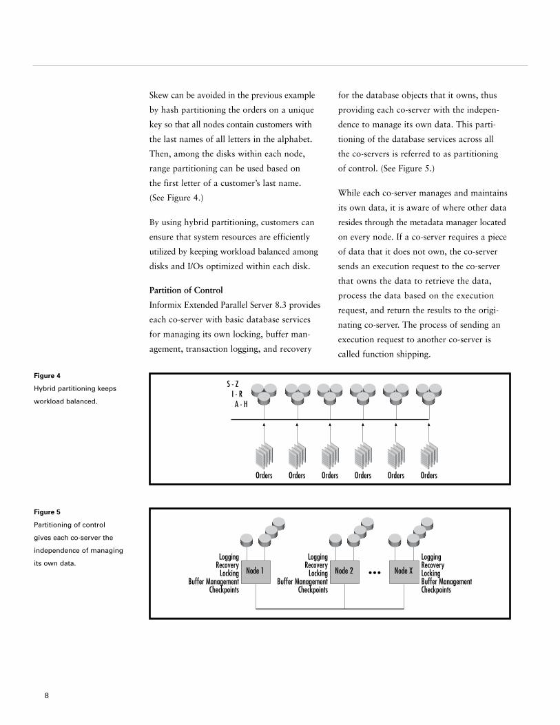
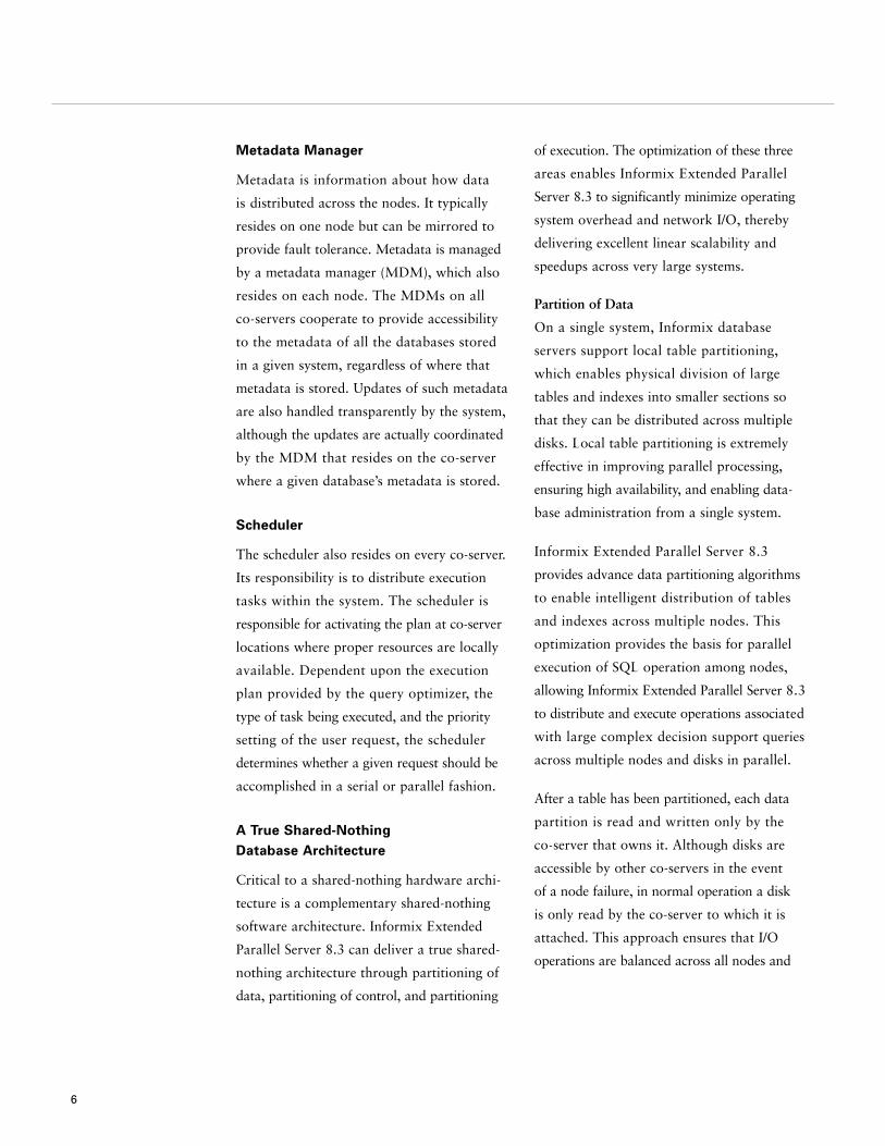
Figure 4
Hybrid partitioning keeps
workload balanced.
Skew can be avoided in the previous example
by hash partitioning the orders on a unique
key so that all nodes contain customers with
the last names of all letters in the alphabet.
Then, among the disks within each node,
range partitioning can be used based on
the first letter of a customer’s last name.
(See Figure 4.)
By using hybrid partitioning, customers can
ensure that system resources are efficiently
utilized by keeping workload balanced among
disks and I/Os optimized within each disk.
Partition of Control
Informix Extended Parallel Server 8.3 provides
each co-server with basic database services
for managing its own locking, buffer man-
agement, transaction logging, and recovery
for the database objects that it owns, thus
providing each co-server with the indepen-
dence to manage its own data. This parti-
tioning of the database services across all
the co-servers is referred to as partitioning
of control. (See Figure 5.)
While each co-server manages and maintains
its own data, it is aware of where other data
resides through the metadata manager located
on every node. If a co-server requires a piece
of data that it does not own, the co-server
sends an execution request to the co-server
that owns the data to retrieve the data,
process the data based on the execution
request, and return the results to the origi-
nating co-server. The process of sending an
execution request to another co-server is
called function shipping.
8
S - Z I - R
A - H
OrdersOrdersOrdersOrders Orders Orders
LoggingRecovery
LockingBuffer Management
Checkpoints
Node 1
LoggingRecovery
LockingBuffer Management
Checkpoints
Node 2
LoggingRecoveryLockingBuffer ManagementCheckpoints
Node X
Figure 5
Partitioning of control
gives each co-server the
independence of managing
its own data.
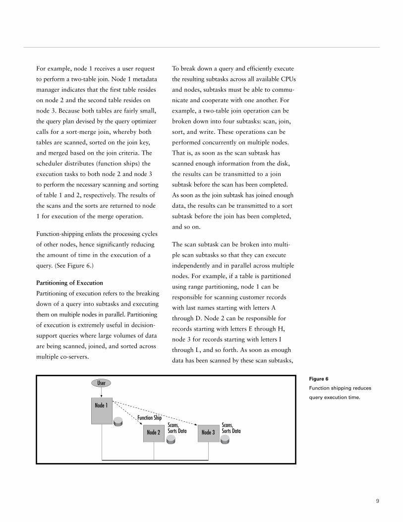
Figure 6
Function shipping reduces
query execution time.
9
For example, node 1 receives a user request
to perform a two-table join. Node 1 metadata
manager indicates that the first table resides
on node 2 and the second table resides on
node 3. Because both tables are fairly small,
the query plan devised by the query optimizer
calls for a sort-merge join, whereby both
tables are scanned, sorted on the join key,
and merged based on the join criteria. The
scheduler distributes (function ships) the
execution tasks to both node 2 and node 3
to perform the necessary scanning and sorting
of table 1 and 2, respectively. The results of
the scans and the sorts are returned to node
1 for execution of the merge operation.
Function-shipping enlists the processing cycles
of other nodes, hence significantly reducing
the amount of time in the execution of a
query. (See Figure 6.)
Partitioning of Execution
Partitioning of execution refers to the breaking
down of a query into subtasks and executing
them on multiple nodes in parallel. Partitioning
of execution is extremely useful in decision-
support queries where large volumes of data
are being scanned, joined, and sorted across
multiple co-servers.
To break down a query and efficiently execute
the resulting subtasks across all available CPUs
and nodes, subtasks must be able to commu-
nicate and cooperate with one another. For
example, a two-table join operation can be
broken down into four subtasks: scan, join,
sort, and write. These operations can be
performed concurrently on multiple nodes.
That is, as soon as the scan subtask has
scanned enough information from the disk,
the results can be transmitted to a join
subtask before the scan has been completed.
As soon as the join subtask has joined enough
data, the results can be transmitted to a sort
subtask before the join has been completed,
and so on.
The scan subtask can be broken into multi-
ple scan subtasks so that they can execute
independently and in parallel across multiple
nodes. For example, if a table is partitioned
using range partitioning, node 1 can be
responsible for scanning customer records
with last names starting with letters A
through D. Node 2 can be responsible for
records starting with letters E through H,
node 3 for records starting with letters I
through L, and so forth. As soon as enough
data has been scanned by these scan subtasks,
Function Ship
Node 2Scans,Sorts DataNode 3
Scans,Sorts Data
Node 1
User
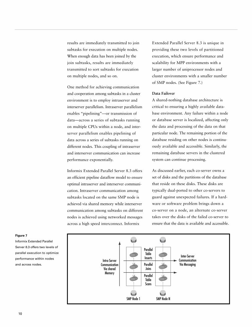
Figure 7
Informix Extended Parallel
Server 8.3 offers two levels of
parallel execution to optimize
performance within nodes
and across nodes.
results are immediately transmitted to join
subtasks for execution on multiple nodes.
When enough data has been joined by the
join subtasks, results are immediately
transmitted to sort subtasks for execution
on multiple nodes, and so on.
One method for achieving communication
and cooperation among subtasks in a cluster
environment is to employ intraserver and
interserver parallelism. Intraserver parallelism
enables “pipelining”—or transmission of
data—across a series of subtasks running
on multiple CPUs within a node, and inter-
server parallelism enables pipelining of
data across a series of subtasks running on
different nodes. This coupling of intraserver
and interserver communication can increase
performance exponentially.
Informix Extended Parallel Server 8.3 offers
an efficient pipeline dataflow model to ensure
optimal intraserver and interserver communi-
cation. Intraserver communication among
subtasks located on the same SMP node is
achieved via shared memory while interserver
communication among subtasks on different
nodes is achieved using networked messages
across a high speed interconnect. Informix
Extended Parallel Server 8.3 is unique in
providing these two levels of partitioned
execution, which ensure performance and
scalability for MPP environments with a
larger number of uniprocessor nodes and
cluster environments with a smaller number
of SMP nodes. (See Figure 7.)
Data Failover
A shared-nothing database architecture is
critical to ensuring a highly available data-
base environment. Any failure within a node
or database server is localized, affecting only
the data and processing of the data on that
particular node. The remaining portion of the
database residing on other nodes is continu-
ously available and accessible. Similarly, the
remaining database servers in the clustered
system can continue processing.
As discussed earlier, each co-server owns a
set of disks and the partitions of the database
that reside on these disks. These disks are
typically dual-ported to other co-servers to
guard against unexpected failures. If a hard-
ware or software problem brings down a
co-server on a node, an alternate co-server
takes over the disks of the failed co-server to
ensure that the data is available and accessible.
10
Intra-ServerCommunication
Via sharedMemory
Inter-ServerCommunicationVia Messaging
ParallelTable
Inserts
ParallelJoins
ParallelTableScans
SMP Node 1 SMP Node N

Figure 8
Dual-ported disks ensure
high availability.
11
For example, suppose Informix Extended
Parallel Server 8.3 is running on three separate
nodes. Co-server 1 owns disks 1 and 2, co-
server 2 owns disks 3 and 4, and co-server 3
owns disks 5 and 6. To ensure continuous
availability in the event of a failure, disks 1
and 2 are dual-ported to co-server 2, disks 3
and 4 are dual-ported to co-server 3, and disks
5 and 6 are dual-ported to co-server 1. The
dotted lines in Figure 8 represent the way
disks are dual ported.
In the event of a failure, the alternate co-server
takes over ownership of the data disks and
logs belonging to the failed node. This process
is also known as data failover. After the
alternate co-server has taken over the disks
on the failed node, fast recovery is performed
to restore the affected portion of the data-
base to a physical and logical consistency.
When recovery is complete, all operations
are dynamically redistributed to the alter-
nate nodes.
Using the example below, should node 2
or co-server 2 fail unexpectedly, co-server 3
takes over disks 3 and 4 to ensure continuous
data availability on these disks (see Figure 9.)
Co-server 1 Co-server 2 Co-server 3
Log 1Disk1 & 2 Log 2
Disk3 & 4 Log 3
Disk5 & 6
Figure 9
Informix Extended Parallel
Server 8.3 data failover.
Co-server 1 Co-server 2 Co-server 3
Log 1Disk1 & 2 Log 2
Disk3 & 4 Log 3
Disk5 & 6

Figure 10
A star schema
database design.
The shared-nothing database architecture
provides a solid foundation for maximizing
performance, scalability, and availability.
To further refine its efficiency for data ware-
housing environments, Informix Extended
Parallel Server 8.3 incorporates a host of
high-end features and enhancements designed
specifically for decision support processing.
These features and enhancements include:
• a new database design to simplify access
and analysis of data;
• support for very large databases;
• new indexing methods to speed up access
to data;
• enhanced join methods to optimize
performance of join operations; and
• SQL extensions to increase the speed of
execution for large, decision support queries.
Simplify Data Access and Analysis
Through Star Schema
To ensure easy access to vast amounts of
data, Informix Extended Parallel Server 8.3
supports a dimensional database design
known as star schema. (See Figure 10.) Star
schema simplifies access and analysis of
information, allowing complex and analytical
queries to be processed in a fraction of the
time it would take with a traditional relational
database design.
Star schema is ideal for data warehouse
applications because it is designed and tuned
to support analysis of business trends and
projections. It differs from typical OLTP
database design in that it provides a query-
centric view of the data. Whereas an OLTP
database tends to organize data around
specific processes (such as order entry), star
Optimized for Data Warehouse/Decision Support Processing
12
CUSTOMERDimension
cidgenderaddresscitystateziphobby
SALESFact
sidcidpidsales_datedollar_salesdollar_costunit_salesdepartment
PRODUCTDimension
pidSKUcategorysizeweightpackage_type
TIMEDimension
datemonthquarteryearholiday_figweekday_fig

13
schema answers questions such as “What
products are selling well?” “What time of
year do products sell best?” and “Which
regions have the weakest sales?”
Star schema divides data into two categories:
facts and dimensions. Facts are the core data
elements being analyzed and dimensions are
attributes about the fact. Figure 10 illustrates
a dimensional database, where SALES is the
fact table and CUSTOMER, PRODUCT, and TIME
are the dimension tables.
Star schema’s intuitive method of represent-
ing data allows users to easily formulate
queries and go directly to the key facts
using a set of familiar dimensions. It can
also provide significant performance advan-
tages, processing complex, analytical queries
in a fraction of the time required by OLTP
database systems.
Informix Extended Parallel Server 8.3 also
supports 3NF and derivative data structures.
Very Large Data Storage Capacity
The amount of data stored in data ware-
house is increasing at a rapid pace. Only a
few years ago, data warehouses could be
measured in megabytes or a few gigabytes.
Today, driven by the increasingly competitive
business landscape, users are loading and
analyzing an immense amount of historical
data into data warehouses to assist with their
business decisions. Therefore, it is of the
utmost importance that the DBMS managing
the data warehouses efficiently handle very
large volumes of data.
With a storage capacity in the multiterabyte
range, Informix Extended Parallel Server 8.3
is designed to support the largest data ware-
houses in the world. Furthermore, Informix
continues to make enhancements in the con-
figuration parameter of Informix Extended
Parallel Server 8.3, ensuring customers that
the database server accommodates their
continuing storage needs.
Fast Data Access Through Efficient
Indexing Methods
For a number of releases, Informix has provid-
ed B-tree indexes for fast retrieval of data.
B-tree indexes have been very effective in the
OLTP arena for retrieving a small number of
selected rows (sometimes referred to as low-
percentage selectivity). DSS applications, by
contrast, tend to retrieve a larger number of
rows (or high-percentage selectivity), making
random access through a single index more
expensive than reading all of the rows in
the table in order.
Informix Extended Parallel Server 8.3 offers
a host of new indexing methods specifically
designed to improve data access for decision
support queries. These new DSS indexing
methods are fully integrated with the query
optimizer; consequently, they can take
advantage of parallel query execution and
parallel index creation. When created, the
indexes improve performance over a wide
range of DSS queries, simplify management
of DSS systems, and are completely transparent
to application users.
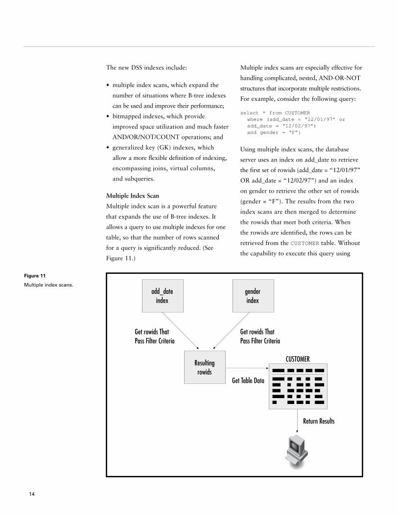
Figure 11
Multiple index scans.
The new DSS indexes include:
• multiple index scans, which expand the
number of situations where B-tree indexes
can be used and improve their performance;
• bitmapped indexes, which provide
improved space utilization and much faster
AND/OR/NOT/COUNT operations; and
• generalized key (GK) indexes, which
allow a more flexible definition of indexing,
encompassing joins, virtual columns,
and subqueries.
Multiple Index Scan
Multiple index scan is a powerful feature
that expands the use of B-tree indexes. It
allows a query to use multiple indexes for one
table, so that the number of rows scanned
for a query is significantly reduced. (See
Figure 11.)
Multiple index scans are especially effective for
handling complicated, nested, AND-OR-NOT
structures that incorporate multiple restrictions.
For example, consider the following query:
select * from CUSTOMERwhere (add_date = “12/01/97” or add_date = “12/02/97”)and gender = “F”;
Using multiple index scans, the database
server uses an index on add_date to retrieve
the first set of rowids (add_date = “12/01/97”
OR add_date = “12/02/97”) and an index
on gender to retrieve the other set of rowids
(gender = “F”). The results from the two
index scans are then merged to determine
the rowids that meet both criteria. When
the rowids are identified, the rows can be
retrieved from the CUSTOMER table. Without
the capability to execute this query using
14
add_dateindex
Resultingrowids
genderindex
Get rowids ThatPass Filter Criteria
Get rowids ThatPass Filter Criteria
Get Table Data
CUSTOMER
Return Results

15
multiple index scans, the database server
would have to perform a sequential scan or
use only one index.
Multiple-column indexes are sometimes
used instead of multiple index scans to
achieve the same effect. However, it is
important to understand that multiple column
indexes work very differently than multiple
index scans in that they require all column
combinations to be computed ahead of time.
This makes multiple-column indexes some-
what restrictive, because not all queries involve
the same columns. To resolve this, one would
have to create many permutations of multiple
column indexes, which would be a tremendous
waste of storage space, making them far less
useful than multiple index scans.
Sequential Skip Scan
Sequential skip scan is different from a
normal index scan that retrieves one row at a
time. Typically, with a normal index scan, the
rowid is read from the index and then used
to retrieve the row from the table. This is
somewhat inefficient since rowids are not
sorted in any physical order, resulting in
random access of the pages. Furthermore,
if accesses for rows that are close together
are not retrieved at the same time, a page can
be reread multiple times. This is a tremendous
waste of system resources.
Performance of index scans can be drastically
improved through the use of sequential skip
scans. With a sequential skip scan, rowids are
sorted and presented in order. Thus, a scan
through the table can pick the next page that
has the relevant rows, skipping those pages
that do not have the rows. If the page has
more than one row, then a single read for
the page picks up all rows that are in that
page. Overall, sequential skip scan results in
significant CPU savings over full table scan,
because the number of rows retrieved for
expression evaluation is significantly reduced.
For example, consider a table in which rows
1, 256, 5000, 30, 4, and 255 need to be
retrieved. Suppose each page in the database
holds 10 rows so that the rows just described
are stored in the following manner:
Row 1 in the first page;
Row 30 in the third page;
Row 256 in the 25th page;
Row 5000 in the 500th page;
Row 4 in the first page; and
Row 255 also in the 25th page.
Normally, if the index is used to look up the
rows, the server would read page 1 to retrieve
row 1, page 3 to retrieve row 30, page 25 for
row 256, page 500 for row 5000, back to
page 1 for row 4, and back to page 25 for
row 255.
However, if sequential skip scan is used, the
rows that need to be retrieved are first sorted
sequentially so that it is presented as rows 1,
4, 30, 255, 256, and 5000. Because rows are
sorted in order, data pages are also read in
order. This eliminates random I/Os and ensures
that a page is read only once. Additionally,
sequential skip scan disregards all non-involved
data pages, thus skipping over pages, 2, 4
through 24, and 26 through 499.
Bitmapped Indexes
Bitmapped indexing has become a popular
method for indexing data in the data ware-
house arena. The basic idea behind this
method of indexing is to use a single bit
to indicate that a specific value of a column
is associated with a particular row, such
that the bit is set to 1 if the entity has the
attribute; otherwise the bit is set to 0. The
relative position of the bit within the string
of bits (or bitmap) is then mapped to the
relevant rowid.
A key advantage of using bitmapped indexes
is the potential for reduction in storage over-
head. For example, instead of using 32 bits
to store the rowid of a record with “sports”
as the department value, a single bit can be
used to indicate whether the department has
the value “sports.” If there are 100 million
rows in the table, a bitmap indicating which
of the rows have DEPARTMENT = “sports”
would require 100 million bits, or about
12.5MB, versus a potential of hundreds of
megabytes using other methods.
Each attribute value has its own bitmap. For
example, if the department attribute has four
possible values: “sports”, “automotive”,
“garden supplies”, and “electronics,” and a
bitmap for DEPARTMENT = “sports”,
DEPARTMENT = “automotive”, DEPARTMENT
= “garden supplies”, and DEPARTMENT =
“electronics”. This means that as the
possible values for an attribute increase,
which is sometimes referred to as high
cardinality, the storage space saving starts to
diminish. For this reason, bitmapped indexes
are best suited for attributes that have fewer
values, or low cardinality.
Informix bitmapped indexes use a B-tree
implementation to increase efficiency and to
reduce storage space. This implementation
uses B-tree access to indicate the values of
each attribute. The relevant bitmap for the
value is then stored at the leaf pages. The
bitmap avoids storing rowids as part of the
index, thus further reducing storage space.
For example, the bitmap for DEPARTMENT =
“sports” may look like the following:
(000101000010110000101001 . . .)
The bitmap shows that rows 3, 5, 10, 12,
13, 18, 20, 23, and so forth, have the depart-
ment value “sports” (skipping over the first
3 bits for rows 0, 1, and 2).
Operations AND, OR, NOT, and COUNT
Another key advantage of bitmapped indexes
is the tremendous improvement in CPU speed
when performing operations such as AND, OR,
NOT, and COUNT. Informix DSS indexes easily
perform these operations by using simple
programming language algorithms. For
example, consider the following algorithm
performing an AND operation:
for (i = 0; i < n; i++)B3[i] = B1[i] & B2[i];
In this example, B1 is the first index consid-
ered and B2 is the second index. The result
of the AND operation is then placed in a third
index, B3.
Informix DSS indexes use comparable loops
to perform OR and NOT operations, and
even to COUNT the number of 1 bits in a
bitmap that gives the number of rows with
a given property.
16
17
Bitmap Compression
When the number of values for an attribute is
large, the bitmap will be sparsely populated
and can take up a large amount of storage
space. To achieve storage space efficiency
where attribute values are large, bitmaps are
often compressed. However, when bitmaps
are compressed, performing operations such as
AND, OR, NOT, and COUNT using the methods
described previously becomes less efficient.
Thus, an efficient method of bitmap compres-
sion must provide a balance between the
requirement to achieve storage space savings
and support for fast operations of AND, OR,
NOT, and COUNT.
After evaluating and testing several methods
of compression methods, Informix has selected
the most efficient compression method avail-
able. This compression method considers
various different forms of bitmaps and
intelligently switches from one index repre-
sentation to another. By doing so, Informix
can achieve storage-space savings without
affecting the efficiency of AND, OR, NOT, and
COUNT operations.
GK Indexes
To increase performance of queries involving
one or more large tables, Informix Extended
Parallel Server 8.3 introduces generalized key
(GK) indexes. GK indexes—which generalize
the use of indexing to allow a broader range
of queries—offer a simple yet powerful way
of storing the results of a join, expression,
or subquery as a key in a B-tree or bitmap
index. When created, the optimizer auto-
matically applies the indexes to improve
query execution.
Informix Extended Parallel Server 8.3 offers
three different GK indexes, including GK
join index, GK virtual column index, and
GK selective index.
GK Join Index
As mentioned earlier, DSS applications
frequently require joining of multiple tables.
These joins can be performed using several
join methods including nested-loop join, sort-
merge join, and other join methods that are
discussed later in this paper. However, while
join algorithms offer the best possible perfor-
mance for joins that are infrequently used,
many complex DSS queries often implement
joins using the same columns. To accelerate
data access on these joins, Informix introduces
GK join index.
A GK join index is essentially a precompiled
join. It is an index that consists of references
to rows in two or more tables that satisfy
the join condition. These references are joined
at the index and thus the index might be
viewed as a table itself. For example, consider
the following:
create gk index ordersgender on SALES(select as key c.gender
from SALES s, CUSTOMER cwhere s.cid = c.cid)
This statement creates a join index for SALES
and CUSTOMER on the c.gender column.
Figure 12 shows a join index.
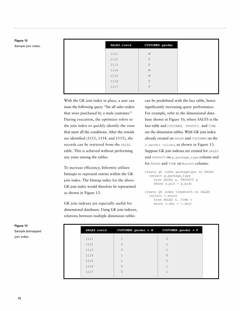
Figure 13
Sample bitmapped
join index.
With the GK join index in place, a user can
issue the following query “list all sales orders
that were purchased by a male customer.”
During execution, the optimizer refers to
the join index to quickly identify the rows
that meet all the conditions. After the rowids
are identified (1111, 1114, and 1115), the
records can be retrieved from the SALES
table. This is achieved without performing
any joins among the tables.
To increase efficiency, Informix utilizes
bitmaps to represent entries within the GK
join index. The bitmap index for the above
GK join index would therefore be represented
as shown in Figure 13.
GK join indexes are especially useful for
dimensional databases. Using GK join indexes,
relations between multiple dimension tables
can be predefined with the fact table, hence
significantly increasing query performance.
For example, refer to the dimensional data-
base shown in Figure 10, where SALES is the
fact table and CUSTOMER, PRODUCT, and TIME
are the dimension tables. With GK join index
already created on SALES and CUSTOMER on the
c.gender column, as shown in Figure 13.
Suppose GK join indexes are created for SALES
and PRODUCT on p.package_type column and
for SALES and TIME on t.month column:
create gk index packagetype on SALES(select p.package_type
from SALES s, PRODUCT pwhere s.pid = p.pid)
create gk index timemonth on SALES(select t.month
from SALES s, TIME twhere s.day = t.day)
18
SALES.rowid
1111
1112
1113
1114
1115
1116
1117
CUSTOMER.gender
M
F
F
M
M
F
F
SALES.rowid
1111
1112
1113
1114
1115
1116
1117
CUSTOMER.gender = M
1
0
0
1
1
0
0
CUSTOMER.gender = F
0
1
1
0
0
1
1
Figure 12
Sample join index.

Figure 14
FCJ I=index representation
for p.package_type, and
t.month.
19
The two GK join indexes created as
described are shown in Figure 14.
After these indexes are created, the
optimizer automatically refers to them
when a query involves joining of the
referenced tables. For example, consider
the following query:
select sum *from SALES s, CUSTOMERS c, PRODUCTS p, TIME t
where s.cid = c.cid and s.pid = p.pid and s.day = t.day and c.gender = ‘M’ and p.package_type = ‘box’ and t.month = ‘Mar’;
SALES.rowid
1111
1112
1113
1114
1115
1116
1117
package_type
= box
0
0
1
1
1
0
0
package_type
= tube
1
0
0
0
0
0
0
package_type
= envelope
0
1
0
0
0
1
1
SALES.rowid
1111
1112
1113
1114
1115
1116
1117
month = JAN
0
1
0
0
1
0
1
month = FEB
0
0
1
0
0
0
0
month = MAR
1
0
0
1
0
1
0
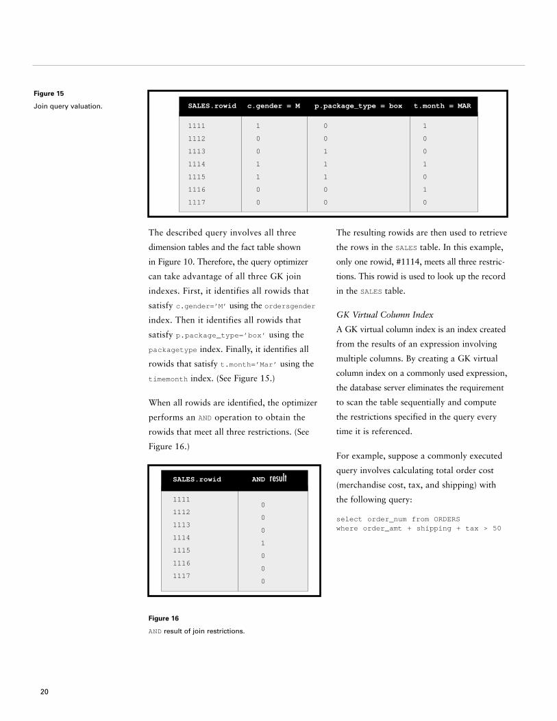
Figure 15
Join query valuation.
The described query involves all three
dimension tables and the fact table shown
in Figure 10. Therefore, the query optimizer
can take advantage of all three GK join
indexes. First, it identifies all rowids that
satisfy c.gender=’M’ using the ordersgender
index. Then it identifies all rowids that
satisfy p.package_type=’box’ using the
packagetype index. Finally, it identifies all
rowids that satisfy t.month=’Mar’ using the
timemonth index. (See Figure 15.)
When all rowids are identified, the optimizer
performs an AND operation to obtain the
rowids that meet all three restrictions. (See
Figure 16.)
Figure 16
AND result of join restrictions.
The resulting rowids are then used to retrieve
the rows in the SALES table. In this example,
only one rowid, #1114, meets all three restric-
tions. This rowid is used to look up the record
in the SALES table.
GK Virtual Column Index
A GK virtual column index is an index created
from the results of an expression involving
multiple columns. By creating a GK virtual
column index on a commonly used expression,
the database server eliminates the requirement
to scan the table sequentially and compute
the restrictions specified in the query every
time it is referenced.
For example, suppose a commonly executed
query involves calculating total order cost
(merchandise cost, tax, and shipping) with
the following query:
select order_num from ORDERSwhere order_amt + shipping + tax > 50
20
SALES.rowid
1111
1112
1113
1114
1115
1116
1117
c.gender = M
1
0
0
1
1
0
0
p.package_type = box
0
0
1
1
1
0
0
t.month = MAR
1
0
0
1
0
1
0
SALES.rowid
1111
1112
1113
1114
1115
1116
1117
AND result
0
0
0
1
0
0
0
21
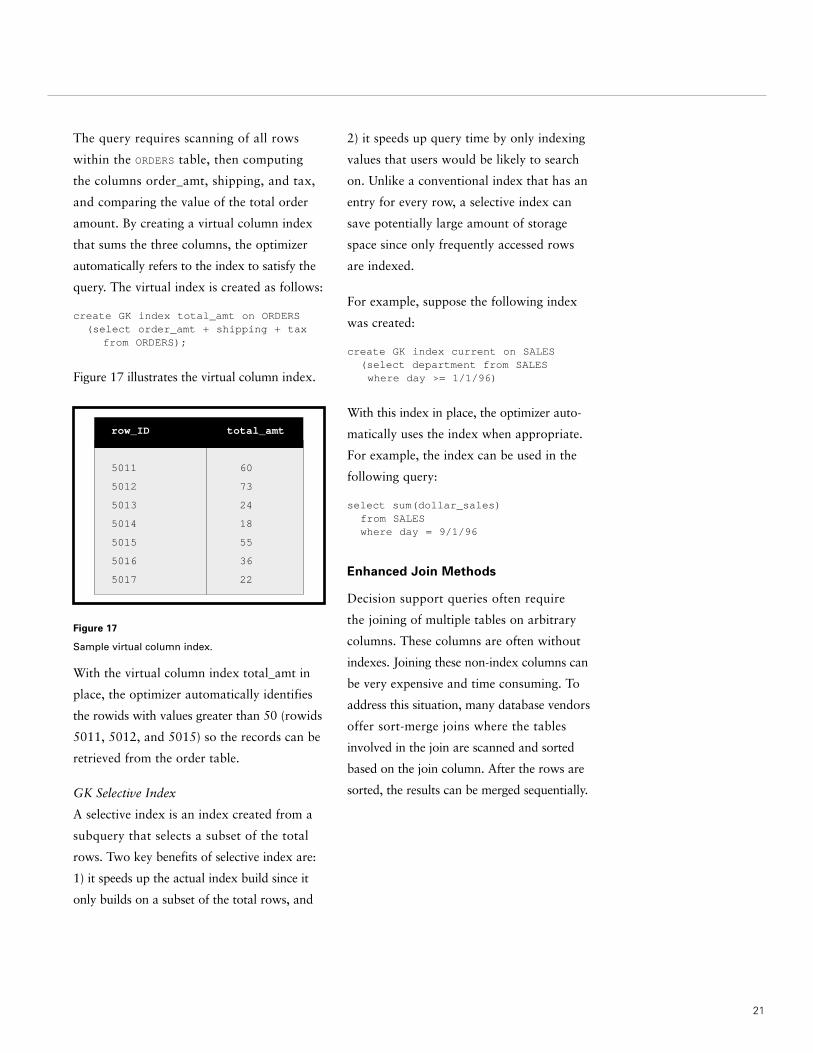
The query requires scanning of all rows
within the ORDERS table, then computing
the columns order_amt, shipping, and tax,
and comparing the value of the total order
amount. By creating a virtual column index
that sums the three columns, the optimizer
automatically refers to the index to satisfy the
query. The virtual index is created as follows:
create GK index total_amt on ORDERS(select order_amt + shipping + tax
from ORDERS);
Figure 17 illustrates the virtual column index.
Figure 17
Sample virtual column index.
With the virtual column index total_amt in
place, the optimizer automatically identifies
the rowids with values greater than 50 (rowids
5011, 5012, and 5015) so the records can be
retrieved from the order table.
GK Selective Index
A selective index is an index created from a
subquery that selects a subset of the total
rows. Two key benefits of selective index are:
1) it speeds up the actual index build since it
only builds on a subset of the total rows, and
2) it speeds up query time by only indexing
values that users would be likely to search
on. Unlike a conventional index that has an
entry for every row, a selective index can
save potentially large amount of storage
space since only frequently accessed rows
are indexed.
For example, suppose the following index
was created:
create GK index current on SALES(select department from SALESwhere day >= 1/1/96)
With this index in place, the optimizer auto-
matically uses the index when appropriate.
For example, the index can be used in the
following query:
select sum(dollar_sales)from SALESwhere day = 9/1/96
Enhanced Join Methods
Decision support queries often require
the joining of multiple tables on arbitrary
columns. These columns are often without
indexes. Joining these non-index columns can
be very expensive and time consuming. To
address this situation, many database vendors
offer sort-merge joins where the tables
involved in the join are scanned and sorted
based on the join column. After the rows are
sorted, the results can be merged sequentially.
row_ID
5011
5012
5013
5014
5015
5016
5017
total_amt
60
73
24
18
55
36
22

Informix offers two additional join methods
to improve the efficiency of joining within
DSS queries. They are hash join and star-
query optimization.
Hash Join
Hash joins are used when one of the two
join tables does not have an index on the
join column, or when the database server
must read a large number of rows from both
tables. This join method is more efficient
than the sort-merge join because no sorting
is required.
With hash joins, one table, generally the
smaller table (also known as build input), is
first scanned and used to create a hash table
based on the conditional expressions within
the WHERE clause (also known as filter).
(See Figure 18.) The hash table can consist
of a series of tables, each having an address
derived from the key value by applying a
hash function. After the first table has been
scanned and placed in the hash table, the sec-
ond table is read sequentially, and each row
is looked up in the hash table to see if a
join can be made. The process of looking
up the hash table by the second table is also
known as the probe phase. (See Figure 19.)
Figure 18
Hash join build phase.
Figure 19
Hash join probe phase.
Often, because the optimizer chooses the
smallest table as the build table, the entire
build input is small enough to be placed
in memory to significantly increase the per-
formance of the join. If the build input does
not fit into memory, it is partitioned by the
hash join build phase, so that a subset of
the table is in memory. Other partitions are
written to disk. When the larger probe table
is read, it is either matched with the hash
table stored memory or written out into a
separate partition file. This process results
in the creation of several probe partitions to
match with the build partitions. When the
probe phase is completed with the first parti-
tion, the next set of build and probe partitions
can be processed independently in pairs.
22
Hash Table
Build Input
Hash TableProbe Phase

23
For example, consider the following query:
select sum(sales.amount)from SALES s, CUSTOMER cwhere s.cid = c.idand c.state = “CA”
Suppose a hash join was used in the query
just described. During the build phase, the
CUSTOMER table is read and a hash table is
created for all IDs that match the join
condition of c.state = “CA”. During the
probe phase, the SALES table is read once,
and each row is matched with IDs in the
hash table. The resulting rows are then
summed to produce the query results.
Hash joins are often more efficient than
a sort-merge join because no sorting is
required. By contrast, a sort-merge join
would require both tables to be sorted;
therefore it becomes less efficient whenever
the join requires large tables.
Star Query Optimization
Star query optimization is a patented algo-
rithm designed to reduce join processing of
queries joining multiple, smaller dimension
tables with a very large fact table. This new
join method increases join efficiency by com-
bining new indexing technologies (bitmapped
filters, multiple index scans, and sequential
skip scan) with the hash join algorithm. When
used successfully, this technique results in a
tremendous reduction in the number of rows
read during the hash join probe phase. The
result is a performance gain of up to 100
times greater with other join methods.
The basic query plan for star query optimiza-
tion involves scanning and applying the filters
to the dimension tables. The resulting rows
are used to build a hash table. While the hash
table is being built, the dimension table
primary keys are “pushed down” to the fact
table. The fact table can use these “push
keys” to perform an efficient index scan or
to construct a bitmap filter. In either case,
rows from the fact table are eliminated
from the probe phase of the hash joins. The
remaining fact table rows are then used for
join processing with all the dimension tables
in a pipeline fashion to complete the query.
For example, consider the following query
using the star schema illustrated in Figure 10:
select c.name, p.name, sum(s.amount)from SALES s, CUSTOMER c, PRODUCT p,
DATE dwhere s.cid = c.cid and
s.pid = p.pid and p.category = “software” ands.did = d.did and d.year = “1998”
group by c.name, p.name;
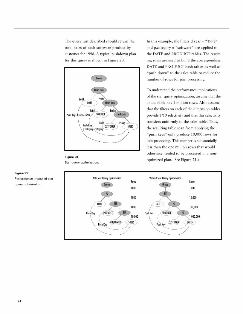
The query just described should return the
total sales of each software product by
customer for 1998. A typical pushdown plan
for this query is shown in Figure 20.
Figure 20
Star query optimization.
In this example, the filters d.year = “1998”
and p.category = “software” are applied to
the DATE and PRODUCT tables. The result-
ing rows are used to build the corresponding
DATE and PRODUCT hash tables as well as
“push down” to the sales table to reduce the
number of rows for join processing.
To understand the performance implications
of the star query optimization, assume that the
SALES table has 1 million rows. Also assume
that the filters on each of the dimension tables
provide 1/10 selectivity and that this selectivity
transfers uniformly to the sales table. Thus,
the resulting table scan from applying the
“push keys” only produce 10,000 rows for
join processing. This number is substantially
less than the one million rows that would
otherwise needed to be processed in a non-
optimized plan. (See Figure 21.)
24
Group
Hash Join
ProbeBuild
ProbeBuild
ProbeBuild
Hash Join
Hash Join
SALESCUSTOMER
PRODUCT
DATE
Push Key: d.year=1998
Push Key: p.category=category
Group
With Star Query OptimizationRows:
1000
1000
1000
10,000
HJ
HJ
HJ
SALESCUSTOMER
PRODUCT
DATE
Push Key
Push Key
Group
Without Star Query OptimizationRows:
1000
10,000
100,000
1,000,000
HJ
HJ
HJ
SALESCUSTOMER
PRODUCT
DATE
Push Key
Push Key
Figure 21
Performance impact of star
query optimization.

25
As mentioned earlier, two methods are
offered to push the filter down to the fact
table. They are referred to as index pushdown
and bit vector pushdown.
Index Pushdown
Index pushdown is implemented by sorting
the primary key of the dimension table and
sending the sorted keys to the fact table scan.
The sorted keys are used to perform index
lookups on the fact table, resulting in a list of
sorted rowids which is then used to perform
a sequential skip scan of the sales table.
Bit Vector Pushdown
With bit vector pushdown, the dimension
table primary key is hashed and used to
set a bit in a bitmap. When the fact table
is scanned, each row is tested against the
bitmap by hashing on the corresponding
foreign key and checking whether the
appropriate bit is set in the bitmap. If the bit
is on, the row is kept for join processing;
otherwise it is discarded.
Star query optimization is completely inte-
grated with the database server. Thus, it is
invoked automatically by the optimizer,
which means no special coding or “hints”
are necessary. This optimization technique
also eliminates the need for a special-purpose
query engine.
Enhanced SQL Extensions
Unlike OLTP operations that are process-
oriented, decision support operations tend to
be very query-centric, thus are often used
to analyze business trends and product
profitability. Understanding that decision sup-
port queries often ask same types of questions,
Informix Extended Parallel Server 8.3 offers
a variety of SQL extensions to speed up the
execution of certain types of DSS queries.
For example, many DSS queries require the
retrieval of first, last, top, or bottom N
records such as the top 10 selling products,
the worst 5 performing regions, the first 100
customer matching a profile, and so forth.
To address these DSS queries, Informix
provides a new SQL extension called First N.
First N lets users specify the number of
records returned from a query. This can
drastically reduce the number of rows shipped
to the clients. For instance, instead of poten-
tially shipping hundreds of rows, only the
top 10 rows are shipped. Additionally, it
can accelerate the sort process, since the sort
process only needs to process a fraction of
the records.

Another new extension, Sampling, lets users
get an approximate idea of what is contained
in a table without having to scan the entire
table. By using Sampling, the user can obtain
important information about a table, such as
sales trends, much faster than executing a
query that scans the entire table. For example,
sampling 1,000 records from a 10 million
row table is significantly faster than reading
all the rows.
Informix Extended Parallel Server 8.3 also
extended the CASE statement to allow
incorporation of conditional expression
within columns as part of an SQL statement.
By using this new SQL extension, users
can significantly reduce the complexity of
database operations.
For example, the following example shows a
CASE statement with multiple expressions:
select case
when sales.amount < 100 then “small sales”
when sales.amount < 1000 then “mid-range sales”
else “large sales”end
from SALESsum (sales.amount)group by 1
Through these new SQL extensions, Informix
significantly increases the speed of execution
for commonly executed decision support
queries. Consequently, critical information
is delivered faster to business managers,
enabling them make key decisions about
their companies’ products and services in
a more timely manner.
26
27
Informix Extended Parallel Server 8.3
incorporates several new features to improve
the management of large data warehouses.
They include a powerful parallel data loader,
an improved algorithm for altering tables,
and tools for enhancing query management.
Query Management
Considering the ad hoc nature of this
environment—an environment in which
the type, quantity, and complexity of queries
being submitted is unpredictable—data
warehouse administrators must be equipped
with query management tools to assist
with controlling the impact of intensive,
concurrent query processing.
Informix Extended Parallel Server 8.3 offers a
unique feature called memory grant manager,
which lets administrators and programmers
control certain aspects of query execution,
such as degree of parallelism, query execution
ordering, and so forth. Informix Extended
Parallel Server 8.3 also provides several
features to offer users more autonomy and
control over the execution ordering of their
queries. These features include scheduling
levels, PDQpriority ranges, and two
admission policies.
Scheduling Levels
Scheduling levels provide a mechanism for
ranking query importance by assigning a value
from 1 through 100 to a query. It denotes the
importance that a user places on a query,
which the database server uses for guidance
when deciding the next query to admit.
PDQpriority Ranges
PDQpriority ranges provide a mechanism
to set an acceptable range of memory for a
query, where the largest PDQpriority value
in the range is the desired resource allocation,
and the smallest PDQpriority value is the
minimum acceptable memory allocation
for the query. For example, a query with a
PDQpriority of 20 to 30 can be started when
25 percent of memory is available. If it had a
value of 30, it would have to wait until the
full 30 percent of resources were available.
PDQpriority range contributes to improved
memory utilization by allowing the database
server to better exploit available memory.
By allowing users to specify an acceptable
range for memory allocation, Informix avoids
situations where a query is blocked when
almost enough memory is available. It also
avoids situations where users may set memory
allocations artificially low to ensure the query
is executed.
Admission Policy
Two policies are available to determine how
scheduling levels and PDQpriority ranges
are used to choose the actual query execution
order. In “strict ordering” the highest level
queries are run first and within each level,
admission is on a first come, first served basis.
This policy could delay a less important query
indefinitely (also known as starvation).
Database Administration and Management
The second policy is “fair ordering” (no
starvation) in which queries are aged based
on scheduling level, PDQpriority, and wait
time. This causes lower level queries that
have been waiting a long time to be executed
ahead of higher level queries with very little
wait time. For queries with equal importance
(same scheduling level), a query with the
lowest PDQpriority tend to be chosen in
favor of queries with higher PDQpriority.
The fair ordering admission policy favors
lower PDQpriority queries based on the
assumption that low PDQpriority queries
are smaller and less complex than high
PDQpriority queries. Reducing the wait time
of small, fast queries can result in improve-
ment in query response time as well as an
increase in system throughput. The additional
wait time for large queries does not significantly
increase response time since it is insignificant
compared to the execution time.
Parallel Loader
With the advent of decision-support applica-
tions, companies today are loading and
unloading large amounts of data from opera-
tional databases into large data warehouses
on a regular basis, sometimes as often as
daily. If the data loaded is incremental, then
the speed of the load is not a great concern.
However, in many cases, the data loaded is a
refresh of the entire database and the perfor-
mance of the database loader becomes critical.
The Informix high-performance parallel
loader utility addresses data loading and
unloading performance by using all the system
resources available, thereby allowing the
data to be loaded and unloaded in parallel,
to and from Informix databases.
The parallel loader utility can load and
unload data very quickly through its ability
to read data from multiple sources and load
data across multiple disks in parallel. This
is achieved through I/O parallelism to and
from media devices, which can significantly
increase the speed of the load over serial load.
This utility is especially important when
loading large databases, enabling customers
to load multiple gigabytes of data per hour.
The Informix high-performance loader also
supports the following key features:
• Data can be loaded or unloaded at the
table-partition level.
• Data can be loaded from or unloaded to
files, tapes, or application pipes.
• A conversion utility supports non-
Informix sources such as binary,
EBCDIC, ASCII, and so forth.
• A GUI interface enhances ease of use.
With the high-performance loader, customers
have the option to disable referential check-
ing, logging, triggers, and drop indexes to
substantially increase the speed of the loading.
Or, if load speed is not a concern, customers
can choose to enforce all database constraints
as the data is added.
28
29
Alter Fragment
After a table and its associated indexes have
been partitioned, they can be altered using
the alter fragment command. One reason
for modifying how tables and indexes are
partitioned is to combine tables that contain
identical table structures into a single
fragmented table (also known as attached
table) or detaching a table fragment from a
fragmentation strategy and place it in a
new table (also known as detached table).
Attached and detached tables are used
often in situations where limited disk space
necessitates moving outdated data from
disks onto other forms of storage media.
A common scenario in which this feature is
useful is when a customer maintains a rolling
window of data. For example, a customer
can have one table that contains 12 months
worth of data, each month within its own
fragment. A second table contains only the
current month’s data. At the end of each
month, customers attach the table containing
the current months data as a new fragment
to the 12 month table. The oldest month’s
data has its fragment detached. This func-
tionality provides customers with a very
clean, very fast import of data with minimal
impact on the base table.
To illustrate, let’s assume that the oldest
month in this case is June 1996 and orders
for this month are stored in dbspace db0696.
The following shows the alter fragment
command to detach dbspace db0696
from the ORDER table and place it into
the old_ORDER table.
alter fragment on table ORDER
detach
db0696 old_ORDER
When created, old_ORDER can be copied
onto another form of storage and deleted
from disk.
To store orders received for the current
month, a new table, new_ORDER, is created.
Because ORDER and new_ORDER use
the same table structure, the alter fragment
command can be used to attach the two
tables into a single fragmented table. The
command for attaching new_ORDER to
ORDER table is shown below:
alter fragment on table ORDER
attach
new_ORDER
Informix Extended Parallel Server 8.3
is designed to respond to the increasing
demand of decision support applications.
Informix Extended Parallel Server 8.3
incorporates a set of robust data warehousing
features to enable fast data access, analysis,
and management. Regardless of the processing
environment and the type of parallel hardware
architecture, Informix Extended Parallel
Server 8.3 delivers the performance and
scalability organizations need to effectively
handle complex, large-scale decision support
operations.
Conclusion
30
About Informix
Informix Corporation, based in Menlo Park, California, provides innovative database solutions
that assist the world’s major corporations attain competitive advantage. Informix is widely
recognized as the technology leader for corporate computing environments ranging from small
workgroups to very large parallel processing applications. Informix’s database server, application
development tools, superior customer service, and strong partnerships enable the company to be
at the forefront of major information technology solution areas including data warehousing, high
performance OLTP, and Web/e-commerce.
For more information, contact the sales office nearest you or visit our Web site at www.informix.com.

4100 Bohannon DriveMenlo Park, CA 94025Tel. 650.926.6300www.informix.com
© 1999 Informix Corporation. All rights reserved. The following are trademarks of Informix Corporation or its affiliates, one or more of which may be registered in theU.S. or other jurisdictions: Informix® and Informix® Extended Parallel Server™ 8.3.
Printed in U.S.A. 10/99000-21924-70
I N F O R M I X R E G I O N A L S A L E S O F F I C E S
Asia Pacific 65 298 1716 Japan 81 3 5562 4500Canada (Toronto) 416 730 9009 Latin America 305 591 9592Europe/Middle East/Africa 44 181 818 1000 North America 800 331 1763Federal 703 847 2900 650 926 6300