Embed Size (px)
Citation preview

DISTRIBUTION STATEMENT A: Approved for public release; distribution is unlimited.
�
NONRESIDENTTRAININGCOURSE
�
October 1997
Information SystemsTechnician Training SeriesModule 3—Network Communications
NAVEDTRA 14224
NOTICE
Any reference within this module to “Radioman” or the former“Radioman rating” should be changed to “Information SystemsTechnician” and the “Information Systems Technician (IT) rating”.The subject matter presented relates to the occupationalstandards for the IT rating.

DISTRIBUTION STATEMENT A: Approved for public release; distribution is unlimited.
Although the words “he,” “him,” and“his” are used sparingly in this course toenhance communication, they are notintended to be gender driven or to affront ordiscriminate against anyone.

i
PREFACE By enrolling in this self-study course, you have demonstrated a desire to improve yourself and the Navy. Remember, however, this self-study course is only one part of the total Navy training program. Practical experience, schools, selected reading, and your desire to succeed are also necessary to successfully round out a fully meaningful training program. COURSE OVERVIEW: In completing this nonresident training course, you will demonstrate a knowledge of subject mattter by correctly answering questions on the following subjects: Network Administration, LAN Hardware, and Network Troubleshooting.
THE COURSE: This self-study course is organized into subject matter areas, each containing learning objectives to help you determine what you should learn along with text and illustrations to help you understand the information. The subject matter reflects day-to-day requirements and experiences of personnel in the rating or skill area. It also reflects guidance provided by Enlisted Community Managers (ECMs) and other senior personnel, technical references, instructions, etc., and either the occupational or naval standards, which are listed in the Manual of Navy Enlisted Manpower Personnel Classifications and Occupational Standards, NAVPERS 18068. THE QUESTIONS: The questions that appear in this course are designed to help you understand the material in the text. VALUE: In completing this course, you will improve your military and professional knowledge. Importantly, it can also help you study for the Navy-wide advancement in rate examination. If you are studying and discover a reference in the text to another publication for further information, look it up.
1997 Edition Prepared by DPC(SW) Walter Shugar, Jr. and RMCS(SW/AW) Deborah Hearn
Reissued on July 2002 to correct minor discrepancies or update
information. No significant change have been made to content.
Published by NAVAL EDUCATION AND TRAINING
PROFESSIONAL DEVELOPMENT AND TECHNOLOGY CENTER
NAVSUP Logistics Tracking Number 0504-LP-026-8630

ii
Sailor’s Creed
“I am a United States Sailor.
I will support and defend theConstitution of the United States ofAmerica and I will obey the ordersof those appointed over me.
I represent the fighting spirit of theNavy and those who have gonebefore me to defend freedom anddemocracy around the world.
I proudly serve my country’s Navycombat team with honor, courageand commitment.
I am committed to excellence andthe fair treatment of all.”

CONTENTS
CHAPTER PAGE
1. Network Administration . . . . . . . . . . . . . . . . . . . . . .1-1
2. LAN Hardware . . . . . . . . . . . . . . . . . . . . . . . . . . . . . . . . .2-1
3. Network Troubleshooting. . . . . . . . . . . . . . . . . . . . . . 3-1
APPENDIX
I. Glossary . . . . . . . . . . . . . . . . . . . . . . . . . . . . . . AI-1
II. Glossary of Acronyms and Abbreviations . . . . . . . . . . . . AII-1
III. References Used to Develop the TRAMAN. . . . . . . . . . . AIII-1
INDEX . . . . . . . . . . . . . . . . . . . . . . . . . . . . . . . . . . INDEX-1
iii
NONRESIDENT TRAINING COURSE follows the index

SUMMARY OF THE RADIOMANTRAINING SERIES
MODULE 1
Administration and Security—This module covers Radioman duties relating toadministering AIS and communication systems. Procedures and guidance forhandling of classified information, messages, COMSEC material and equipment,and AIS requirements are discussed.
MODULE 2
Computer Systems—This module covers computer hardware startup, includingperipheral operations and system modification. Other topics discussed includecomputer center operations, media library functions, system operations, andtroubleshooting techniques. Data file processes, memory requirements, anddatabase management are also covered.
MODULE 3
Network Communications-This module covers network administration, LANhardware, and newtwork trobleshooting. Related areas discussed are networkconfiguration and operations, components and connections, and communicationlines and nodes.
MODULE 4
Communications Hardware—This module covers various types ofcommunications equipment, including satellites and antennas. Subjects discussedinclude hardware setup procedures, COMSEC equipment requirements, distresscommunications equipment, troubleshooting equipment, satellite theory, andantenna selection and positioning.
MODULE 5
Communications Center Operations—This module covers center operations,including transmit message systems, voice communications, center administration,quality control, and circuit setup/restorations. Guidelines for setting EMCON andHERO conditions and cryptosecurity requirements are also discussed.
iv

CREDITS
Trademark Credits
ARCnet is a registered trademark of Datapoint Corporation.
Ethernet is a registered trademark of Xerox Corporation.
Novell is a registered trademark of Novell, Inc.
UNIX is a registered trademark of X/Open Company Ltd.
Windows 3.11 is a registered trademark of Microsoft Corporation.
Windows 95 is a registered trademark of Microsoft Corporation.
Windows NT is a registered trademark of Microsoft Corporation.
v
vi
INSTRUCTIONS FOR TAKING THE COURSE
ASSIGNMENTS
The text pages that you are to study are listed atthe beginning of each assignment. Study thesepages carefully before attempting to answer thequestions. Pay close attention to tables andillustrations and read the learning objectives.The learning objectives state what you should beable to do after studying the material. Answeringthe questions correctly helps you accomplish theobjectives.
SELECTING YOUR ANSWERS
Read each question carefully, then select theBEST answer. You may refer freely to the text.The answers must be the result of your ownwork and decisions. You are prohibited fromreferring to or copying the answers of others andfrom giving answers to anyone else taking thecourse.
SUBMITTING YOUR ASSIGNMENTS
To have your assignments graded, you must beenrolled in the course with the NonresidentTraining Course Administration Branch at theNaval Education and Training ProfessionalDevelopment and Technology Center(NETPDTC). Following enrollment, there aretwo ways of having your assignments graded:(1) use the Internet to submit your assignmentsas you complete them, or (2) send all theassignments at one time by mail to NETPDTC.
Grading on the Internet: Advantages toInternet grading are:
• you may submit your answers as soon asyou complete an assignment, and
• you get your results faster; usually by thenext working day (approximately 24 hours).
In addition to receiving grade results for eachassignment, you will receive course completionconfirmation once you have completed all the
assignments. To submit your assignmentanswers via the Internet, go to:
https://courses.cnet.navy.mil
Grading by Mail: When you submit answersheets by mail, send all of your assignments atone time. Do NOT submit individual answersheets for grading. Mail all of your assignmentsin an envelope, which you either provideyourself or obtain from your nearest EducationalServices Officer (ESO). Submit answer sheetsto:
COMMANDING OFFICERNETPDTC N3316490 SAUFLEY FIELD ROADPENSACOLA FL 32559-5000
Answer Sheets: All courses include one“scannable” answer sheet for each assignment.These answer sheets are preprinted with yourSSN, name, assignment number, and coursenumber. Explanations for completing the answersheets are on the answer sheet.
Do not use answer sheet reproductions: Useonly the original answer sheets that weprovide—reproductions will not work with ourscanning equipment and cannot be processed.
Follow the instructions for marking youranswers on the answer sheet. Be sure that blocks1, 2, and 3 are filled in correctly. Thisinformation is necessary for your course to beproperly processed and for you to receive creditfor your work.
COMPLETION TIME
Courses must be completed within 12 monthsfrom the date of enrollment. This includes timerequired to resubmit failed assignments.

vii
PASS/FAIL ASSIGNMENT PROCEDURES
If your overall course score is 3.2 or higher, youwill pass the course and will not be required toresubmit assignments. Once your assignmentshave been graded you will receive coursecompletion confirmation.
If you receive less than a 3.2 on any assignmentand your overall course score is below 3.2, youwill be given the opportunity to resubmit failedassignments. You may resubmit failedassignments only once. Internet students willreceive notification when they have failed anassignment--they may then resubmit failedassignments on the web site. Internet studentsmay view and print results for failedassignments from the web site. Students whosubmit by mail will receive a failing result letterand a new answer sheet for resubmission of eachfailed assignment.
COMPLETION CONFIRMATION
After successfully completing this course, youwill receive a letter of completion.
ERRATA
Errata are used to correct minor errors or deleteobsolete information in a course. Errata mayalso be used to provide instructions to thestudent. If a course has an errata, it will beincluded as the first page(s) after the front cover.Errata for all courses can be accessed andviewed/downloaded at:
https://www.advancement.cnet.navy.mil
STUDENT FEEDBACK QUESTIONS
We value your suggestions, questions, andcriticisms on our courses. If you would like tocommunicate with us regarding this course, weencourage you, if possible, to use e-mail. If youwrite or fax, please use a copy of the StudentComment form that follows this page.
For subject matter questions:
E-mail: [email protected]: Comm: (850) 452-1501
DSN: 922-1501FAX: (850) 452-1370(Do not fax answer sheets.)
Address: COMMANDING OFFICERNETPDTC N3116490 SAUFLEY FIELD ROADPENSACOLA FL 32509-5237
For enrollment, shipping, grading, orcompletion letter questions
E-mail: [email protected]: Toll Free: 877-264-8583
Comm: (850) 452-1511/1181/1859DSN: 922-1511/1181/1859FAX: (850) 452-1370(Do not fax answer sheets.)
Address: COMMANDING OFFICERNETPDTC N3316490 SAUFLEY FIELD ROADPENSACOLA FL 32559-5000
NAVAL RESERVE RETIREMENT CREDIT
If you are a member of the Naval Reserve,you may earn retirement points for successfullycompleting this course, if authorized undercurrent directives governing retirement of NavalReserve personnel. For Naval Reserve retire-ment, this course is evaluated at 3 points. (Referto Administrative Procedures for NavalReservists on Inactive Duty, BUPERSINST1001.39, for more information about retirementpoints.)


ix
Student Comments
Course Title:Information Systems Technician Training SeriesModule 3—Network Communications
NAVEDTRA: 14224 Date:
We need some information about you:
Rate/Rank and Name: SSN: Command/Unit
Street Address: City: State/FPO: Zip
Your comments, suggestions, etc.:
Privacy Act Statement: Under authority of Title 5, USC 301, information regarding your military status isrequested in processing your comments and in preparing a reply. This information will not be divulged withoutwritten authorization to anyone other than those within DOD for official use in determining performance.
NETPDTC 1550/41 (Rev 4-00


CHAPTER 1
NETWORK ADMINISTRATION
Upon completing this chapter, you should be able to do the following:
Describe how to establish communications with remote terminals andmonitor system transmissions.
Describe how to start up, monitor, and terminate network processing.
Explain how to change network software configurations and how to analyzenetwork hardware configurations.
Explain how to install and test software and how to perform systemrestorations.
Explain how to evaluate network requests.
Describe the procedures used to calculate network capacity.
Explain how to determine communications protocols and how to design anetwork.
Welcome to the wonderful world of networking.Networking has opened the world to connectivity.Networking gives an individual the capability tocommunicate and connect with another individual oranother system in order to share resources.
The end result is to establish communicationsbetween two PC computers or two entirely differentsystems. The process used to reach that point can bedone many ways. Once you have establishedconnectivity and are communicating, then you willneed to monitor the systems transmission to ensure thetwo computers are, in fact, communicatingsuccessfully. Some of the factors that will have to betaken into consideration are:
What type of hardware will be needed
What operating system (OS) will be used
What applications will be needed
What type of cabling will be used
NETWORK OPERATIONS
Networks consist of nodes that are interconnectedby links. These nodes and links usually cover a
relatively small geographical area, commonly known asa local area network, ranging from a few feet to a mile.Nodes are the hardware, such as computers, terminals,hard disks, printers, and so on. Links are thecommunications media, such as twisted-pair wire,coaxial cable, or fiber optic cable that connects thenodes.
Networks are made up of a variety of hardware,network software, connecting cables, and networkinterface cards combined in any number of ways. Andthat is perfectly OK. Quite often, we design a networkusing existing hardware. That is just one of the manyreasons why each individual network has its ownunique characteristics. The network hardware andsoftware components determine the structure of anetwork, whether it is a local, metropolitan, or wide areanetwork. Normally, the workstations (PCs) in a LANare in close proximity to each other, usually within thesame building. A metropolitan area network (MAN)consists of PCs that are basewide: one commandconnected with another command, or one baseconnected with another base, all via phone lines. A widearea network (WAN) is worldwide: one countryconnected with another country via satellites, etc.
1-1

A network could be made up of 13 PCs, a serverwith a hard disk, 3 printers, and a plotter. Anothernetwork could be made up of 6 PCs (one of which is thenetwork server) and a laser printer. Both are networks.When you connect individual PCs together (via cable),and each PC is allowed access to the other’s informationand/or resources, you have created a network (see figure1-1). By connecting PCs in this fashion, you are able toshare all sorts of things. Examples are information infiles; software, such as word processors, spreadsheetprograms, and utilities; and peripheral devices, such ashard disks, printers, plotters, and fax machines.
A network gives you the capability of transferringdata, files, programs, you name it, from one PC toanother or even from one network to another. You cantransfer a report or listing to any printer you desire onthe network, provided you have access to the printer.How is that for flexibility? By connecting your PC intoa network system, you can execute applicationprograms stored on the server’s hard disk withouthaving to worry about disk space or keeping track ofdiskettes. You can exchange files and programs withother users directly without copying them onto adiskette. Can you begin to see the power and flexibilitybuilt into a network system?
COMMUNICATIONS WITH REMOTETERMINALS
The ability to connect to the LAN through the use ofremote terminals gives you great flexibility, whether itis being able to check your E-mail via a modem or checkthe status of the LAN by connecting to the network as a
Figure 1-1.—Connecting PCs to form a local area network.
remote console. The remote capabilities will increaseproductivity. The network supervisor can manage thesystem by establishing communications through aremote terminal.
Logins from Remote Locations
Remote access refers to logins from remotelocations. These login procedures are accomplished bydialing into an access server (a special modem orcomputer) and logging in through this server.
The network modems that can be used as remoteaccess servers must have a network interface card (NIC)compatible with the network to which the modem isproviding access. Remote connections often requirespecial timing considerations, because many networktransactions must happen within a very limited timeperiod.
Remote Console
A networking utility that enables a networksupervisor to manage a server from a workstation orfrom a remote location using a modem. The supervisorcan give commands and accomplish tasks just as if allthe commands were being given directly at the server bysimulating a direct connection to the server.
NETWORK STARTUP/SHUTDOWN
Keeping the system running is the most visibleaspect of system administration. You’re the one theywill call when the system has gone down (crashed). Wewill discuss the normal UNIX booting (startup) andshutdown processes. Shutting down and bringing up aUNIX system is actually very simple.
System Startup
Every time the system is booted, a series of stepsmust be performed before the system becomes availableto users. Booting is the process of bringing a computersystem up and making it ready to use.
The process begins when some instructions storedin ROM are executed which load the program boot fromthe boot partition into system memory. Boot loads thebootable operating system, which is also called thebootable kernel. The bootable kernel starts the init(initialization) program.
INIT.— One of the first things init does is checkavailable memory, Next, it checks out the environmentto see what hardware is present. When the kernel is
1-2
configured, it is told what types of hardware devices toexpect. Init will search for and attempt to initialize eachphysically attached device. Any device that does notinitialize or that is missing will be marked asnonexistent and the driver disabled. Even if the deviceis later reconnected, it will be unusable until the systemis rebooted.
When all is ready, the kernel verifies the integrity ofthe root filesystem and then mounts it. Init does the restof the work that is needed in preparing the system forusers. This includes mounting the remaining local diskpartitions (those found in the file /etc/checklist);performing some filesystem cleanup operations (fsck);turning on the major UNIX subsystems, such asaccounting and the print service; starting the network;mounting remote file systems; and enabling user logins.
SYSTEM MODES.— There are two primarymodes of system operation: single-user and multi-user.Single-user is a system state designed for administrativeand maintenance activities which require complete andunshared control of the system. Single-user mode issometimes called the maintenance mode. Single-usermode is entered via manual intervention during the bootprocess. Sometimes, however, the system will entersingle-user mode if there are problems in the bootprocess that the system cannot handle on its own.Multi-user allows many users to all log onto the sameCPU. Users can access different applicationssimultaneously or even the same applicationsimultaneously. The kernel manages the different usersby scheduling the use of the processing time as well asswapping programs and data in and out of memorythrough virtual memory to disk. The most importantfact to remember is that the number of concurrent usersdepends on the amount of memory installed in thecomputer. Each user has a certain amount of memoryset aside for his or her work, unless everyone is willingto tolerate slow response time from the network.
System Shutdown
While there are many occasions when shuttingdown or rebooting the system is appropriate, neitheroperation should be performed indiscriminantly. Whileit is generally not something to worry about, there is adegree of hardware fatigue associated with turning acomputer system off and on again, and it is often betterto let it run 24 hours a day than to shut it down at night.
REBOOTING.— There are only four commonsituations in which rebooting the system is called for:
If you make changes to any of the systemsoftware or configuration files that are examinedor executed only when the system is booted, youmust reboot for these changes to take effect.
Some devices, especially printer and modemports, can become confused enough thatresetting them is only accomplished by re-initializing the system.
If the system has been up and running constantlyfor over a week, it is wise to bring the systemdown to single-user mode and run fsck. If anyfixes are made to the root partition, the systemmust be rebooted.
If the system console becomes irretrievablyhung, the system must be rebooted.
SHUTTING THE SYSTEM DOWN.— There aretwo proper ways to shut down the operating system:shutdown and reboot. As a last resort, the system can beshut down by turning off the power to the CPU. Thismethod is recommended only under emergencyconditions because of its detrimental impact on systemfiles and certain types of hard disk drives. These diskdrives expect their floating heads to be parked prior toshutdown. Powering off the system could cause theheads to crash and cause irreparable damage to the disk.
Shutdown.— This command is the most often usedmethod of initiating a orderly system shutdown. It is thesafest, most considerate, and most thorough to initiate ahalt, reboot, or return to single-user mode. Thecommand will send messages to each user’s terminal atprogressively shorter intervals as the time for shutdownapproaches. The messages tell the time of theshutdown.
Reboot.— This command terminates all currentlyexecuting processes except those essential to thesystem, then halts or reboots the system. When invokedwithout arguments, reboot syncs all disks beforerebooting the system. The command does not send amessage out to the users, unless you use the messageoption.
MONITOR
Some people would ask, “Why do I have to expendenergy on monitoring the network when I could bedoing something more productive, like file server orworkstation maintenance?” There are several reasonswhy you should monitor your network:
1-3
To maintain a history of the performance of yoursystem. Studying this history could point outpotential failures long before they occur.
To provide a statistical basis for new equipmentrequests. Management is more likely to purchasenew equipment if you can demonstrate that thecurrent equipment will not meet the company’sneeds.
To enable you to tune your network for optimumperformance. This is especially true on largernetworks with more than one file server. In somecases, you can provide a perceived increase inthroughput by simply transferring tasks from oneserver to another.
Various network operating systems (NOSs) havetheir own utility programs to monitor what processing istaking place on their network. You can use theseprograms to monitor the status of your network, andsome utilities give you the capability to monitor aparticular job request.
REVIEW AUDIT LOGS
The main importance of reviewing audit/event logsis to monitor the security of the system. Besides, C2Security compliance requires that the system bemonitored (audited) continuously. Whether it pertainsto the system – what hardware was accessed, security –identify who logged on (logged-in), or application –what software was accessed; usage must be tracked.
The term auditing refers to the process of recordingevents, such as file access, creations, deletions, theaddition of print jobs, and so on, and using thatinformation to detect usage violations or to confirm thatnetwork procedures are operating correctly.
A network administrator, by using the audit logs,can track what files were accessed, when they wereaccessed (date and time), by whom, and even whattransactions were performed. Some logs even show youif the transaction was or was not successful with sometype of message.
NETWORK CONFIGURATION
Equipment, the connections, and equipmentsettings for a network comprise the networkconfiguration. The equipment refers to the hardware(computers, peripherals, boards, and cables), but mayalso include software under certain circumstances.
Because of equipment compatibility andinteroperability, a system administrator needs to knowconsiderable detail about all of the equipment thatcomprises the network. This information may includemodel numbers, memory specifications, enhancements,and so on. This information must be maintained, orconflicts between the equipment may occur. Mostnetworking systems include a utility for recordingsystem configuration information and updating it as thenet work changes.
Record the current settings for each component aspart of the configuration information. Avoid conflictswhen deciding on specific settings. A conflict can arisebecause two boards want to use the same memorylocation or interrupt.
SYSTEM PARAMETERS
System parameters must be verified prior toinstallation and startup to avoid any conflicts. Themajority of the conflicts involve system interrupts. Aninterrupt is a mechanism by which one computingelement, such as a modem or a program, can get theattention of another elements. Interrupts may begenerated by hardware or software.
Hardware Interrupt
There are 16 interrupt request lines (IRQs) forhardware interrupts in a PC environment. Each deviceattached to a computer can have an IRQ assigned.When the device wants service from the CPU, it signalson this line and waits.
IRQs have different priority levels, and the higherpriority lines are assigned to the most importantfunctions on the PC. By responding to IRQs accordingto their assigned priority, an operating system orinterrupt handler can ensure that no vital activities areinterrupted.
IRQ values for a device may be set throughsoftware or by manually setting them through the use ofjumpers or DIP switches on the expansion board for thedevice. When configuring devices, it is important thatyou do not have two devices that use the same IRQ.
Software Interrupt
Executing programs also use interrupts to getresources needed to perform some action. There aresoftware interrupts to access a monitor screen or diskdrive, to handle a keystroke or a mouse click, and so on.
1-4

There are software interrupts for handling specificrequests and for performing specific actions (forexample, determining memory size). Interrupts canprovide access to more functions (for example, DOSinterrupt 2AH provides for network control functions).
SOFTWARE CONFIGURATIONS
All of the software that will be installed on thenetwork will be configured for use on the system.Unfortunately, the manufacturers can’t configure thesoftware to function properly on each and every system.It will be up to you to make configuration changes to getthe optimum performance from the specific softwarethat will be loaded on the network.
These changes can include one or more of thefollowing:
Available memory
Type of peripheral (e.g., disk or tape drives,printers, etc.)
Number of users
Access speeds
Available disk space
Before making any changes to the software, ensurethat there are adequate backups available to restore thesystem if problems are encountered. The mostimportant thing to remember, when making changes, isto read the installation instructions that were suppliedby the manufacturer first.
NETWORK PARAMETERS
If you think about the network, its performance isgoverned by both the hardware and software. Thehardware has certain limitations that are set by themanufacturer and can’t be changed. You can’t speed updisk or memory access times, no matter what you do.The software, however, can be changed to help makethe network run better.
Setting Parameters
Although the software is designed to run at theoptimal rate, because each system is different there aresome changes that can be made. Changes to thesesettings can allow the system to run even better, usingall of its resources.
Some of these setting changes include:
Adjusting memory partitions
Drive/directory access
Number o f u se r s
This is by no means a complete list of possiblechanges that can be made; refer to the operator’s manualfor your specific software for changes that can be made.
Modifying Parameters
The modification of the network parameters onyour specific system will depend on the software beingused. Each manufacturer sets up the software to run atoptimal performance. There will be times that thenetwork’s performance falls off because of addingadditional equipment, creating the need to change theparameters. When the parameters must be changed,always refer to the operator’s manual for the specifics.
A number of parameters can be changed to improvethe network’s performance, including increasing theamount of memory used for disk sharing, printspooling, and printing. By increasing the buffer usedfor transferring files between the file server andworkstations, the file server does not have to perform asmany send operations and can perform other networkprocedures more quickly. By increasing the size of thebuffer used for handling user requests, more userrequests can be processed and the network can performfaster.
NETWORK PORT CONFIGURATION
A port is a connection on the back of the computerwhere you connect peripherals, switches, networks, orother devices. The port provides the electrical andphysical interface between the device and the computer.There are two types of ports:
Parallel: A hardware connection used to send orreceive a lot of data over a short distance. Theseports typically send eight bits of datasimultaneously.
Serial: A hardware connection that is used tosend data one bit at a time and is very good forsending information over a long distance.
Port Address or Name
A port address is a bus or memory address that isassociated with a particular hardware port. The port
1-5

will have at least enough storage allocated to handle thedata being written or read at the port.
A port name can be used instead of an address torefer to a port. A name is normally easier to rememberthan an address. Operating systems sometimes havepredefine names associated with certain ports. Forexample, DOS reserves COM1 and LPT1 to refer to thefirst serial and parallel ports, respectively.
ANALYZE CONFIGURATION
Analyzing the configuration of the network can beaccomplished in two different ways. The first andsimplest way happens when the computer is turned on;the operating system goes out and checks theconfiguration. The second way is accomplished byusing an application to test whether a remote device isproperly connected to the system. The use of anapplication is the best way to analyze the configuration.
The application tests the remote device by sendingout a signal to each device and waiting for the signal toreturn. This process is called “pinging.” The ping sentout is called an echo message, and the reply is called anecho reply message. The application sends out the echomessage and, if the device is properly connected, itsends back an echo reply message. The receipt of thisecho reply indicates that there is a viable connection.Some version of application software reports on howlong it took to receive the echo reply and any lostreplies. These reports provide information about thetraffic and noise levels on the network.
SYSTEM RESOURCE LIMITS
The advantage of a network is it allows severalpeople to share resources, both hardware and software.Hardware resources refer to printers, disk drives, CD-rom drives, scanners, and modems. Software resourcesinclude operating system, drivers, applications (wordprocessing, database, etc.), management software, anddata files. To avoid problems, such as slow responsetime and unavailability of resources, you must know thelimits of the system resources.
Hardware Limits
The limitation involved with hardware is going tobe waiting. A particular piece of peripheral equipmentcan be accessed by one user at a time. Only one job canbe printed at a time, and only one user can be using asingle modem at a time. This small inconvenience ofaccess outweighs the cost of several different pieces ofthe same type (i.e., several printers or modems).
Software Limits
No matter which software package, whetherapplication, mail, or operating system, there is a limitednumber of users that can use the software at one time. Itis far cheaper to buy one multi-user package that allowsfor 25 users than to purchase 25 individual copies. But,it might run just a bit slower than an individual copy.
NETWORK SOFTWARE
Networks require the interaction of software andhardware. The system software to operate and controlthe network must be specifically designed for networkoperation. The application software/programs to solveuser problems must also be specially designed to run ona network. Between the system software and theapplication software/programs, two pieces of softwareare needed. One is the telecommunications accesssoftware. It provides application programs access tothe network so they can send and receive data. Theother is the teleprocessing monitor, which is theinterface between the telecommunications accesssoftware and the application programs. It handles thedetails of integrating these two. To install the systemsoftware, as with any software, follow the installationinstructions supplied with the software.
SYSTEM SOFTWARE
It takes special system software to handle theunique and dynamic workloads of a network. Thisspecial software is called network system software.The network system software is sometimes referred toas the network operating system (NOS). It is differentfrom the type of system software you normally use onyour stand-alone PC. Network system software must beable to handle multiple users, multiple peripherals,network security, and be able to share information andapplication software, just to name a few differences.Normally, network system software runs on the networkserver. It includes such things as the network’soperating system software, communications software,and all the programs needed to manage the sharing ofinformation and resources on the network. Without it,there would be no way to coordinate and manage themany components of a network into a functioningwhole.
Network system software provides multitaskingcapabilities. If the network is to serve multiple users atthe same time, then the server must be able to performtasks so fast they appear to be processed
1-6

simultaneously. An example of multitasking is to havethe network server transfer a message (using a programcalled E-mail) from one PC to another, save a 50-pagedocument to hard disk, and send a report to a printer, inrapid succession. Only systems with multipleprocessors, such as a system with two 386 or 486microprocessors, can process informationsimultaneously.
Network system software provides utilityprograms, such as electronic mail (or e-mail). E-mailgives network users the ability to send messages to oneanother over the network. If for some reason youneeded to send a message to all the network users,E-mail is capable of sending your message to multipleusers. Other utility programs sort, merge, and printfiles.
Network system software also provides dataprotection. This includes data security/integrity andbacking up of files. Data security is a must if you are tolimit access to sensitive and classified information.Data integrity prevents files from being updated bymore than one user at a time. There are a number ofways you can control access to information on thenetwork. One way is to divide the shared hard disk intoseveral different sections, similar to making logicalpartitions. Once the different areas have beenestablished, you can specify how the user can accessthem. Generally, the different levels of access can bedesignated for either private, shared, or public use. Theyare defined as follows:
PRIVATE USE Only one user is allowed toaccess and make changes to the data in this area.For example, all of PO1 Smith’s work is locatedin the area \SMITH. Only PO1 Smith has accessto this area, and only she can make changes.
SHARED USE All users are allowed to accessand make changes to the data in this area. Forexample, a shared area called \ADMIN couldcontain correspondence that can be updated byall the command’s Yeomen.
PUBLIC USE All users are allowed to accessthis area; however, they cannot make anychanges to the data. For example, the area called\DIRECTIV contains all command directives.You would want your users to be able to view thedata but not be able to make any changes.
Security and data protection are provided byidentification and password security. When the userslog on the system, they must enter their correct
identification numbers along with their passwords (as adouble check) to gain access to information. Anotherreason why data must be made secure is to preventunintentional damage that can result when more thanone user accesses and changes the same information atthe same time. In a case such as this, neither user wouldknow what the other had done, and the result would becorrupted data. To prevent this, network software oftenprovides you with some type of locking capability.This locking feature prevents others from accessing thefile or record when you are working on it.
To ensure a well-managed (network), the data mustnot only be secure, it must also be backed upon a regularbasis. Files must be backed up if all the information onthe network server’s hard disk is to be saved in the eventof a hard disk failure, a sudden power surge, or loss ofpower. Tape backup systems are very effective in thatnot only the tapes but also the tape units themselves canbe stored off-site, which provides for additionalsecurity.
APPLICATION SOFTWARE
In addition to network system software, users of(network) require application software to carry outtheir specific requirements. You are familiar with manyof the application software functions/packagesavailable. They include word processing programs,database management programs, spreadsheetprograms, computer aided design (CAD) programs,tutorials, and so on. Application software shared on anetwork is different from the software you use on yourindividual or stand-alone PC. It is specially designed towork on a network—to handle the demands of manyusers and to share resources while serving many users.It can also provide data security features, such as file orrecord locking and password recognition. Becausenetwork versions of application software are designedto be used by many users, a network software licenseagreement often costs more than a standard license.
Before leaving this section, you need to know a fewother things about network software. Network systemsoftware features often vary from one network systemto another. The system software can also dictate whathardware components CAN and CANNOT be used,and how the network CAN or CANNOT be configured.
SOFTWARE INSTALLATION
Before installing software on an individual’s PC oron the network server, you will need to know theminimum system/hardware requirements for that
1-7

software. You will normally find this information onthe side of the box and sometimes even on the back ofthe box the software comes in. The followingrequirements and recommendations will normally belisted:
Any other system/hardware requirements that maybe needed will also be listed. As an example, theserequirements might include: one CD-ROM drive;microphone, for voice annotation feature; a mouse orcompatible pointing device; 2400 or higher baudmodem (9600 baud modem recommended);headphones or speakers; and type of messagingsoftware required to use e-mail; etc.
Once you have determined all of the aboveinformation, you will need to determine whether it will
be run on a network as shared. Before you install thesoftware, you need to read the installation instructionsthat come with the software application in their entirety.It is strongly suggested that you read a file normally
called the “READ. ME” file, because that is where youwill find the most up-to-date information (changes) thathave been made to the application.
1-8
SOFTWARE TESTING
Once the software is installed on the network, itmust be tested. The reason for the testing is to make surethat all aspects of the program work. There are twoavenues for testing the software: an independent testingcompany, and end-users.
The advantage of an independent testing companyis that it will use a more comprehensive and systematictesting method. Testing aimed at the generic networkuser is the disadvantage of the testing company.
Using end-users has both advantages anddisadvantages when it comes to testing the software. Anadvantage is that the end-users will test all facets of thesoftware. A disadvantage is the haphazard methods ofmost end-users when it comes to testing the software.
SYSTEM RESTORATION
The network is the most error-prone of the systemcomponents. Usually, multiple vendors are involved,and too few qualified personnel are available to supportall the implemented networks. Due to these inherentproblems with the network, system degradation is a partof operation, and getting the system back into normaloperation is of great importance.
Three primary methods are used to provide servicerestoration after system degradation. They are asfollows:
Redundancy. Redundancy refers to duplicatehardware and network facility segments that areavailable at all times. If the primary path fails, asecondary path can continue network operation.
Rerouting. Rerouting is the transmission ofinformation along alternative paths. The end-to-endtransmission initially required is still obtained.
Reconfiguration. Reconfiguration is themanual or automatic reconfiguration of equipmentand/or lines to achieve the original end-to-endconnections. Reconfiguration may be the most costlymethod in time because it requires knowledgeablepersonnel and the appropriate switching of equipment.
These three modes of operation are short-termsolutions meant to keep information moving. A bettersolution is to correct the degraded or failed circuitand/or equipment so normal operation is restored.

NETWORK DESIGN
The first step in designing a network is to decidewhether or not a network is needed. This decision ismade easier by soliciting network requests from thecommand. Once the decision is made to design andinstall a network, you need to look at the capacity andreliability of the network and the design options.
Many design options are available for designingand building a LAN. Four interrelated factorscontribute to this great flexibility. They are physicallayout (topology), access method (protocol), physicalconnection (cabling), and networking operating system(NOS). There is one additional factor to be consideredwhen designing a network, the need for security. Thisneed for security is met by the implementation of afirewall.
NETWORK REQUESTS
Before committing the money to install a network,you need to research the need for a network for thecommand. The best way to conduct this research is byusing a network request. Always make sure you haveall the available information to guide your planning.The following are some guidelines to use whenbeginning to plan for a network:
Calculate your needs as completely as possible.This will help you decide what components andservices will need to be included in the network.
Determine what resources are available at yourcommand for planning, implementing, andrunning a network.
Determine who needs access to the network andwhere these people are located. Thisinformation will help determine whether anetwork is a necessary or feasible solution for thecommand’s needs. It will also provideinformation regarding cabling requirements.
Get to know the current usage and needs indetail. This information will also help decidewhether a network is the best solution.
Get a detailed drawing of office locations,existing wiring, and possible server locations.
After gathering and evaluating the information, thedecision can be made as to whether or not a network isthe way to go. If it is decided to go with a network, it istime to determine what resources are available.
CALCULATING NETWORKCAPACITY
After you’ve determined the available resources,use only a portion of these for your workingcalculations. This downsizing will protect you againstthe losses of these resources.
The amount by which you should decrease yourestimates depends on the possible costs if your networkis a failure and on how stable the resources are. Ageneral rule to follow is to assume that your availableresources will be anywhere from 10 to 50 percent lessthan estimated. Let’s say, that you have 25 PCworkstations available to connect to the network. Youshould plan on connecting 22 (12% less than available),which would leave you with 3 spare workstations.Another example would be: if your NOS is capable ofhaving 250 accounts, reducing this quanity by 10% (25)will help reduce the time that the users will be waitingfor the network to respond to their request.
The opposite of this rule is applied when it comes tothe cost calculations. When you decide how much timeand money it is going to cost, it is a good idea to add anamount or a percentage to the calculations. Projects likenetworks never seem to be completed on time or at cost,due to unforeseen circumstances.
LAN CONFIGURATIONS (TOPOLOGIES)
The physical arrangement of a LAN’s componentsis called its configuration or topology. The three majortypes of LAN configurations, or topologies, are thestar, the bus, and the ring. You can also create hybridtopologies by combining features of theseconfigurations. For example, several bus networks canbe joined together to form a ring of buses.
Each topology requires LAN components to beconnected in a different arrangement. Thesecomponents are also referred to as nodes. Remember, anode is any point on a network where data can be sent(transmitted) or received—a workstation, server, and soon.
The Star Network
In a star network, each component is connecteddirectly to the central computer or network server, as
1-9
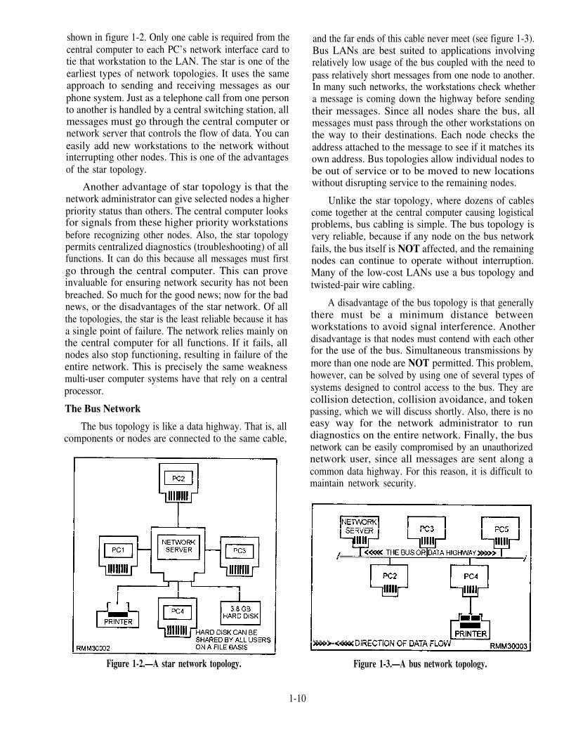
shown in figure 1-2. Only one cable is required from thecentral computer to each PC’s network interface card totie that workstation to the LAN. The star is one of theearliest types of network topologies. It uses the sameapproach to sending and receiving messages as ourphone system. Just as a telephone call from one personto another is handled by a central switching station, allmessages must go through the central computer ornetwork server that controls the flow of data. You caneasily add new workstations to the network withoutinterrupting other nodes. This is one of the advantagesof the star topology.
Another advantage of star topology is that thenetwork administrator can give selected nodes a higherpriority status than others. The central computer looksfor signals from these higher priority workstationsbefore recognizing other nodes. Also, the star topologypermits centralized diagnostics (troubleshooting) of allfunctions. It can do this because all messages must firstgo through the central computer. This can proveinvaluable for ensuring network security has not beenbreached. So much for the good news; now for the badnews, or the disadvantages of the star network. Of allthe topologies, the star is the least reliable because it hasa single point of failure. The network relies mainly onthe central computer for all functions. If it fails, allnodes also stop functioning, resulting in failure of theentire network. This is precisely the same weaknessmulti-user computer systems have that rely on a centralprocessor.
The Bus Network
The bus topology is like a data highway. That is, allcomponents or nodes are connected to the same cable,
Figure 1-2.—A star network topology.
and the far ends of this cable never meet (see figure 1-3).Bus LANs are best suited to applications involvingrelatively low usage of the bus coupled with the need topass relatively short messages from one node to another.In many such networks, the workstations check whethera message is coming down the highway before sendingtheir messages. Since all nodes share the bus, allmessages must pass through the other workstations onthe way to their destinations. Each node checks theaddress attached to the message to see if it matches itsown address. Bus topologies allow individual nodes tobe out of service or to be moved to new locationswithout disrupting service to the remaining nodes.
Unlike the star topology, where dozens of cablescome together at the central computer causing logisticalproblems, bus cabling is simple. The bus topology isvery reliable, because if any node on the bus networkfails, the bus itself is NOT affected, and the remainingnodes can continue to operate without interruption.Many of the low-cost LANs use a bus topology andtwisted-pair wire cabling.
A disadvantage of the bus topology is that generallythere must be a minimum distance betweenworkstations to avoid signal interference. Anotherdisadvantage is that nodes must contend with each otherfor the use of the bus. Simultaneous transmissions bymore than one node are NOT permitted. This problem,however, can be solved by using one of several types ofsystems designed to control access to the bus. They arecollision detection, collision avoidance, and tokenpassing, which we will discuss shortly. Also, there is noeasy way for the network administrator to rundiagnostics on the entire network. Finally, the busnetwork can be easily compromised by an unauthorizednetwork user, since all messages are sent along acommon data highway. For this reason, it is difficult tomaintain network security.
Figure 1-3.—A bus network topology.
1-10

Figure 1-4.—A ring network topology.
The Ring Network
In a ring network, all of the components or nodesare connected to the main cable, and the cable forms aring, as shown in figure 1-4. This topology allows anode to send a message to another node on the ring.However, the message must be transmitted througheach node until it reaches its destination. Messagesproceed from node to node in one direction only.Should anode fail on the network, data can no longer bepassed around the ring unless the failed node is eitherphysically or electronically bypassed. Using bypasssoftware, the network can withstand the failure of a
workstation by bypassing it and still be able to maintainthe network’s integrity. One of the major issues in a ringtopology is the need for ensuring all workstations haveequal access to the network.
One of the major disadvantages of ring topologies isthe extreme difficulty of adding new workstations whilethe network is in operation. Normally, the entirenetwork has to be brought down while a new node isadded and cabling reattached. However, this particularproblem can be overcome by initially setting up thenetwork with additional connectors. These connectorsenable you to add or remove nodes while the networkremains intact and in operation. The addition of theconnectors is accomplished with the addition of amultistation access unit (MAU). The MAU is a wiringconcentrator which allows workstations to be eitherinserted or bypassed on the ring.
The Distributed Star (Tree) Network
The distributed star or tree topology (figure 1 -5) canprovide many of the advantages of the bus and the startopologies. It connects workstations to a central point,called a hub. This hub can support several workstationsor hubs which, in turn, can support other workstations.Distributed star topologies can be easily adapted to thephysical arrangement of the facility site. If the site has ahigh concentration of workstations in a given area, thesystem can be configured to more closely resemble a
Figure 1-5.—A distributed star (tree) network topology.
1-11

star topology. If the workstations are widely dispersed,the system can use inexpensive hubs with long runs ofshared cable between hubs, similar to the bus topology.
PROTOCOLS
Network protocols are an important component;they define how networks establish communicationsbetween elements, exchange information, andterminate communications. Protocols have two majoroperational functions. They establish the circuit fortransmission (handshaking) and for the transmissionitself. Transmission is conducted subject to the linedicipline. The line discipline is the sequence ofoperations that actually transmits and receives the data,handles the error-control procedures, handles thesequencing of message blocks, and provides forvalidation for information received correctly.
Two representative protocols, which control linedic ip l ine , a re : the Binary SynchronousCommunications Protocol (Bisync) and theSynchronous Data Link Control (SDLC).
and protocol. The principal access methods arecontention and token passing.
Contention
The contention method features Carrier SenseMultiple Access (CSMA) and Carrier Sense MultipleAccess with Collision Detection (CSMA/CD). (Seefigure 1-6.) Access for both is on “a first-come, first-served basis. The CSMA scheme is very similar to acitizens band (CB) radio. Stations with data to sendlisten to the channel and wait until it is clear to transmit.With CSMA/CD, if two or more workstations transmitsimultaneously, their messages will collide. As soon asa workstation detects a collision, it ceases transmission,monitors the network until it hears no other traffic, andthen retransmits. Most contention networks assign aunique retry algorithm to vary the wait-and-retryperiod. This algorithm reduces the likelihood that aftera collision, two workstations will transmit retriessimultaneously.
Bisync is a half-duplex protocol that transmitsstrings of characters at lower speeds over dial-upcircuits. Information movement is one direction at atime, with each data transfer being answered by anacknowledgement.
SDLC is a control procedure that sends multipleblocks of data and returns a single acknowledgementfor many blocks, thereby increasing the amount of timespent transmitting data. The bits that are put before andafter the message at the transmitting end are removed atthe receiving end, so only the message is presented tothe user.
The hardware chosen for the network plays apart inthe choice of network protocol. Most users and many ofthe vendors that build clone-type equipment would liketo see universal interfaces. Others feel that theavailability of different specifications will lead to aproprietary set of equipment, even though they favor theoverall IS0 specifications (which are covered later inthis chapter).
ACCESS METHODS
Another decision to be made is which accessmethod to use. Access methods are the arrangementsused to ensure that each workstation has fair and equalaccess to the network. The access method that will beused is governed primarily by the network’s topology
Figure 1-6.—A bus network using the CSMA/CD accessmethod.
1-12

Token Passing
Token passing is an orderly access method (figure1-7). Each workstation passes on the opportunity totransmit to its closest neighbor, until a station is foundwith a message to send. This permission to transmit iscalled a token. When a workstation with data to send ishanded a token, part of the token is changed, indicatingit is carrying a message, and then data is transmittedwith the token. The token is then passed around thenetwork, and every station checks to see if the messageis intended for them. The receiving station copies themessage from the token but then passes the unchangedtoken along the network. When the transmitting stationreceives the same token, it knows the message has beenpassed around the network. The transmitting stationerases the message and puts the empty token back intocirculation on the network. The amount of informationthat may be transmitted during possession of the tokenis limited so that all workstations can share the cableequally.
Network Standards
These access methods (CSMA/CD, CSMA/CA,and token passing) with their transmission medium(twisted-pair wire, coaxial cable, or fiber optic cable),are just one of several aspects (or levels) of an entireLAN structure. The topologies and network accessmethods just presented only establish a way to connectworkstations or nodes together and how to pass alongpackets of data. These packets of data may beprograms, data, system or personal messages, and so on.Above this hardware/software level are a number ofother levels that are just as important in a LAN’s design.These are the levels that define how the LAN systemmanages its resources, how a user like yourself is able tolog onto another node’s hard disk, how a common laser
Figure 1-7.—A ring network using the token passing accessmethod.
printer is used by all nodes, how one file is passedamong many users, and so on. If order and disciplineare to be maintained on the network, standards orprotocols must be established and adhered to. Thisallows the LAN to function in an efficient and effectivemanner.
Over the past few years, a number of networkstandards or protocols have been developed by theInternational Standards Organization (ISO). Theyprovide some level of uniformity among computermanufacturers and network vendors. ISO is one ofseveral governing organizations in this field that hasdeveloped a series of protocols (rules to live by) toensure compatibility for the many different vendorswho design network hardware and software products.IS0 has defined a seven-layer architecture. These sevenlayers of standards, shown in figure 1-8, define ageneralized architecture called the Reference Model ofopen Systems Interconnection. It is also known asthe OSI reference model or OSI model. The primarypurpose of the OSI model is to provide a basis forcoordinating the development of standards that relate tothe flexible interconnection of incompatible systemsusing data communications facilities.
The OSI model does NOT define any one vendor’sparticular network software as such, nor does it definedetailed standards for any given software. It simplydefines the broad categories of functions that each of theseven layers should perform. The OSI model caninclude different sets of standards at each layer that areappropriate for given situations. For example, in a verysimple data communications system, one that uses asimple point-to-point link, the software at the higher-
Figure 1-8.—The OSI model showing the seven softwarelayers.
1-13

level layers (say 5, 6, and 7) might be very simple orpossibly nonexistent. However, in a very complex datacommunications system, all seven software layers maybe implemented. Although there is no requirement forany hardware or software vendor to adhere to theprinciples set forth in the OSI model, there is aworldwide trend in the computer industry towardacceptance and conformance to these standards.
About now, you may be asking yourself, what arethese seven software layers (shown in figure 1-8), andwhy all the need for protocols? Don’t all computerswork in binary? Do they not all have operatingsystems? If a computer wants to communicate withanother system, do you not simply connect themtogether using some type of cable? The answers to thesequestions are yes, yes, and yes; however, thecommonalities seem to stop there.
Ideally, if the hardware, network software,application software, and cabling were all supplied bythe same manufacturer, we would have relatively fewproblems to contend with when we design andimplement a network. Everything would work togetherrather smoothly. However, a computer manufacturer’sarchitecture can make it difficult to interconnecth a r d w a r e o f f e r e d b y o t h e r c o m p e t i n gmanufacturers/vendors. The protocols used bycommunications devices are also highly complex andare often completely different from one manufacturer toanother. Then, there is the network software. Networksoftware from one LAN vendor usually won’t work on acompetitor’s network, nor will the applicationprograms. Even the cabling must be selected for aspecific local-area network.
We could go on and on explaining the manyincompatibilities that exist within these different areas,but the good news is that many hardware and softwaremanufacturers/vendors provide interfaces. Thesevarious types of interfaces (bridges, gateways, routers,and so on) allow networks to be compatible with oneanother. At this point, we briefly talk about the sevensoftware layers defined in the OSI model to give yousome idea of what they are and why they are needed. Toillustrate how the OSI model works, we are using theanalogy of sending a letter using the U.S. postal system.
Layer l—The physical layer is concerned withthe transmission of the unstructured raw bit stream overa physical meduim. It addresses the electrical,mechanical, and functional interface to the carrier. It isthe physical layer that carries the signals for all thehigher layers, as follows:
Voltages and pulse encoding of bits
Media and media interface (cables, connectors,NIC, and so on)
Line discipline (full- or half-duplex)
Pin assignments
In our mail analogy, the mail truck and the highwayprovide the services of the physical layer.
Layer 2—The data link layer provides error-freetransmission of information over the physical medium.This allows the next higher layer to assume virtuallyerror-free transmission over the link. The data link layeris responsible for getting data packaged and onto thenetwork cable. It manages the flow of the data bitstream into and out of each network node, as follows:
Creates and recognizes frame boundaries
Checks received messages for integrity
Manages channel access and flow control
Ensures correct sequence of transmitted data
The data link layer detects, and when possible,corrects errors that occur in the physical layer withoutusing the functions of the upper layers. It also providesflow-control techniques to ensure link-buffer capacityis not exceeded. In our analogy, the data link layer isconcerned with sending the mail trucks onto thehighway and making sure they arrive safely.
Layer 3—The network layer decides whichphysical pathway the data should take, based onnetwork conditions, priorities of service, and otherfactors. Software on the network interface card mustbuild the data packet so the network layer can recognizeand route the data to the correct destination address. Itrelieves the upper layers of the need to know anythingabout the data transmission and switching technologiesused to connect the systems. It is responsible forestablishing, maintaining, and terminating connectionsacross the intervening communications facility, asfollows:
Addresses messages
Sets up the path between communicating nodeson possibly different networks
Routes messages among networks
Is concerned with the sequence delivery of datapackets
1-14

Controls congestion if too many packets are onthe network
Translates logical addresses or names intophysical addresses
Has accounting functions to count packets orbitssent by users to produce billing information
This layer acts in our postal service analogy, like theregional mail distribution centers throughout thecountry. The trucks are directed to the centers and arerouted along the best path to their final destinations.
Layer 4—The transport layer ensures data unitsare delivered error-free, in sequence, with no losses orduplications. It relieves higher layer protocols from anyconcern with the transportation of data between them,as follows:
Message segmentation—accepts data from thesession layer, splits it up into smaller units, andpasses the units down to the network layer
Establishes and deletes host-to-host connectionsacross the network
Multiplexes several message streams onto onechannel and keeps track of which messagebelongs to which connection
Provides reliable end-to-end delivery withacknowledgment
Provides end-to-end flow control and windowmanagement
The transport layer functions are provided by the mailtruck dispatcher, who takes over if there is a wreck outin the system. If the network goes down, the transportlayer software will look for alternate routes or perhapssave the transmitted data until the network connection isreestablished.
Layer 5—The session layer allows users ondifferent machines to establish sessions between them.It performs the functions that enable two applications tocommunicate across the network, performing security,name recognition, logging, administration, and othersimilar functions. Unlike the network layer, this layer isdealing with the programs in each machine to establishconversations between them, as follows:
Allows two applications processes on differentmachines to establish, use, and terminate aconnection (or session)
Performs synchronization between end-usertasks by placing checkpoints in the data streamso if the network fails, only the data after the lastcheckpoint has to be retransmitted
Provides dialogue control (who speaks, when,how long, and so on)
The session layer in our postal agency recognizesdifferent zip codes and reroutes letters.
Layer 6—The presentation layer formats data tobe presented to the application layer. It can be viewed asthe translator for the network. This layer provides acommon representation for data that can be usedbetween the application processes. The presentationlayer relieves the applications from being concernedwith data representation, providing syntaxindependence, as follows:
Encodes data in a standard way (integers,floating point, ASCII, and so on)
Provides data compression to reduce the numberof bits that have to be transmitted
Provides data encryption for privacy andauthentication
This layer functions like a translator who translates aletter from French into English.
Layer 7—The application layer serves as thewindow for the application process to access the OSIenvironment. This layer represents the services thatdirectly support users and application tasks. It containsa variety of commonly needed protocols for thefollowing:
Network virtual terminals
File transfers
Remote file access
Electronic mail
Network management
In our analogy, the application layer is the person whowrites or reads the letter.
CABLING
A data communications network must have cablingto allow individual computers and other peripherals totalk to one another and share resources. And wouldn’t itbe easier if there were only one type available? There
1-15
would be fewer hassles when it came time to figure outsuch things as line speeds, line capacities, variations inline distortion, and so on. However, there area numberof types, ranging in cost and capabilities. In thefollowing paragraphs, we examine the advantages anddisadvantages of twisted-wire pairs, baseband andbroadband coaxial cabling, and fiber optic cabling.
Twisted-wire Pairs
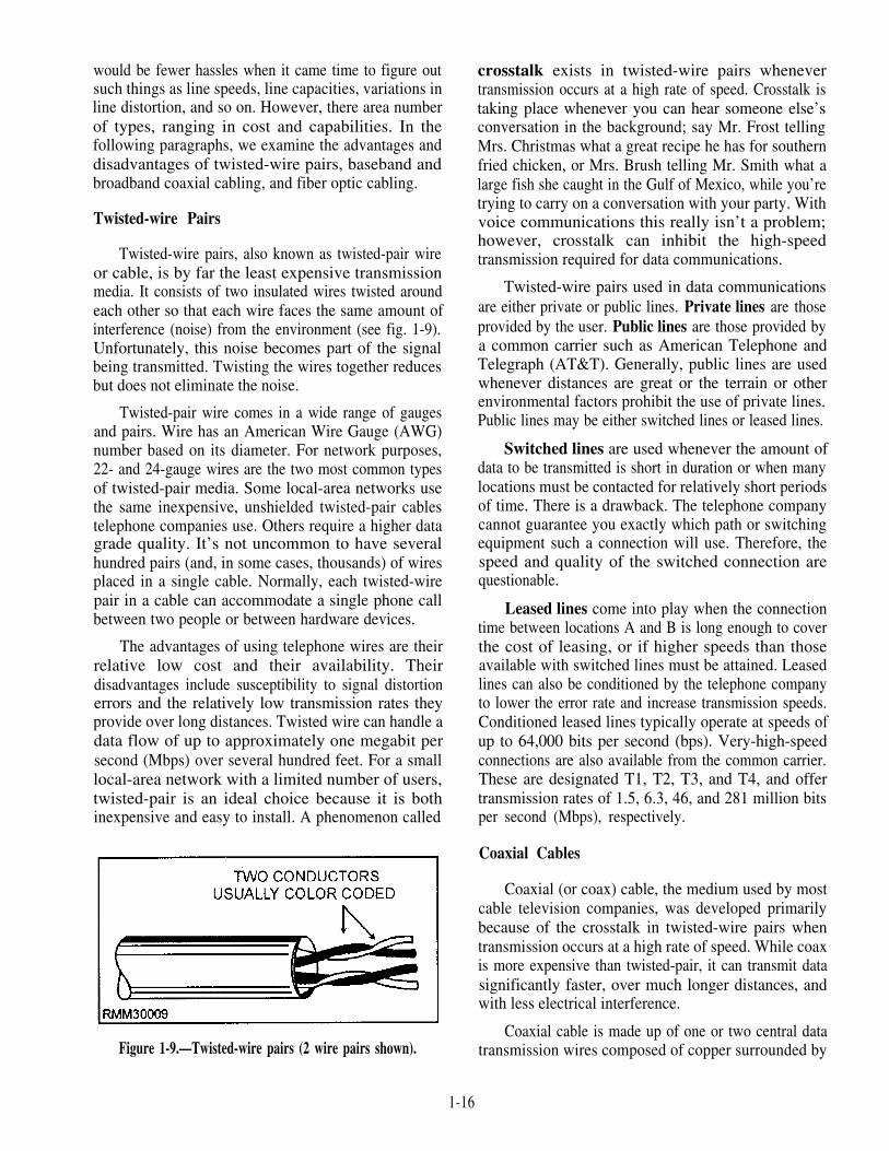
Twisted-wire pairs, also known as twisted-pair wireor cable, is by far the least expensive transmissionmedia. It consists of two insulated wires twisted aroundeach other so that each wire faces the same amount ofinterference (noise) from the environment (see fig. 1-9).Unfortunately, this noise becomes part of the signalbeing transmitted. Twisting the wires together reducesbut does not eliminate the noise.
Twisted-pair wire comes in a wide range of gaugesand pairs. Wire has an American Wire Gauge (AWG)number based on its diameter. For network purposes,22- and 24-gauge wires are the two most common typesof twisted-pair media. Some local-area networks usethe same inexpensive, unshielded twisted-pair cablestelephone companies use. Others require a higher datagrade quality. It’s not uncommon to have severalhundred pairs (and, in some cases, thousands) of wiresplaced in a single cable. Normally, each twisted-wirepair in a cable can accommodate a single phone callbetween two people or between hardware devices.
The advantages of using telephone wires are theirrelative low cost and their availability. Theirdisadvantages include susceptibility to signal distortionerrors and the relatively low transmission rates theyprovide over long distances. Twisted wire can handle adata flow of up to approximately one megabit persecond (Mbps) over several hundred feet. For a smalllocal-area network with a limited number of users,twisted-pair is an ideal choice because it is bothinexpensive and easy to install. A phenomenon called
Figure 1-9.—Twisted-wire pairs (2 wire pairs shown).
crosstalk exists in twisted-wire pairs whenevertransmission occurs at a high rate of speed. Crosstalk istaking place whenever you can hear someone else’sconversation in the background; say Mr. Frost tellingMrs. Christmas what a great recipe he has for southernfried chicken, or Mrs. Brush telling Mr. Smith what alarge fish she caught in the Gulf of Mexico, while you’retrying to carry on a conversation with your party. Withvoice communications this really isn’t a problem;however, crosstalk can inhibit the high-speedtransmission required for data communications.
Twisted-wire pairs used in data communicationsare either private or public lines. Private lines are thoseprovided by the user. Public lines are those provided bya common carrier such as American Telephone andTelegraph (AT&T). Generally, public lines are usedwhenever distances are great or the terrain or otherenvironmental factors prohibit the use of private lines.Public lines may be either switched lines or leased lines.
Switched lines are used whenever the amount ofdata to be transmitted is short in duration or when manylocations must be contacted for relatively short periodsof time. There is a drawback. The telephone companycannot guarantee you exactly which path or switchingequipment such a connection will use. Therefore, thespeed and quality of the switched connection arequestionable.
Leased lines come into play when the connectiontime between locations A and B is long enough to coverthe cost of leasing, or if higher speeds than thoseavailable with switched lines must be attained. Leasedlines can also be conditioned by the telephone companyto lower the error rate and increase transmission speeds.Conditioned leased lines typically operate at speeds ofup to 64,000 bits per second (bps). Very-high-speedconnections are also available from the common carrier.These are designated T1, T2, T3, and T4, and offertransmission rates of 1.5, 6.3, 46, and 281 million bitsper second (Mbps), respectively.
Coaxial Cables
Coaxial (or coax) cable, the medium used by mostcable television companies, was developed primarilybecause of the crosstalk in twisted-wire pairs whentransmission occurs at a high rate of speed. While coaxis more expensive than twisted-pair, it can transmit datasignificantly faster, over much longer distances, andwith less electrical interference.
Coaxial cable is made up of one or two central datatransmission wires composed of copper surrounded by
1-16

an insulating layer, a shielding layer, and a weatherproof outer jacket, as shown in figure 1-10. It is almostas easy to install as twisted-pair, and is the preferredmedium for many of the major local-area networks.Coaxial cable is used extensively in local-area networkswhenever the distance involved is relatively short,generally less than 2 miles for baseband LANs and 10miles for broadband LANs. It is used in both basebandand broadband networks. Wait a minute! You say youwant to know what the terms baseband and broadbandmean and how they relate to networks? Not to worry;we explain them to you a little later in the text, but fornow, all you need to know is that they both deal with theway data is transmitted (in the form of electrical signals)through some type of medium.
Fiber Optic Cable
Fiber optic cable is to coaxial cable is to twisted-pair as the F-18 Hornet is to the Corvette is to the modelT. It is the newest of the communication mediums, onethat was spurred by the development of lasertechnology. Fiber optic cable (shown in fig. 1-11)consists of thousands of clear glass fiber strands, eachapproximately the thickness of a human hair.Transmission is made possible by the transformation ofdigital data into modulated light beams, which are sentthrough the cable by a laser light-emitting diode (LED)type device at incredibly fast speeds. Transmissionrates available (as of 1990) range up to approximately 1billion (or giga) bits per second (Gbps), with speedsover 2 Gbps possible. When thinking in terms offrequencies, light frequencies are extremely high. Theyare approximately 600,000 times that of the highesttelevision channel. In terms of data communications,the higher the frequency of the signal, the moreinformation it can carry. Put simply, every hairlike fiberwithin a fiberoptic cable has the capacity to carry manyhundreds of local-area network channelssimultaneously. When dealing with fiber optic cable,you will hear such terms as:
Figure 1-10.—Coaxial cable,
Figure 1-11.—Fiber optic cable.
Monomode— Single fiber cable
Multimode— Several fibers within a cable
Graded index— A variation of multimode
Some of the major advantages of fiber optics overwire media include speed, size, weight, longevity, andresistance to tapping without being noticed. Since itcarries no electrical current, it is immune to electricalinterference of any kind, and there is no worry of itbeing a shock hazard.
One big disadvantage of fiber optic is the tighterrestrictions on how much the cable can be bent. Otherdisadvantages include higher cost, and the inability toadd on new workstations while other stations are active.Although it is relatively easy to splice the fiber opticcable and add new stations, the network or a portion ofthe network must be down while preparing the splice.On the other hand, if your activity has seriousinterference problems, or has a need for absolutenetwork security, or the need to send signals severalmiles, then fiber optics might be the only solution.
Cable Selection
About now, you may be asking yourself, why all thefuss over transmission speeds? Why not just simplychoose the cheapest transmission medium available anduse it? It may not be the ideal situation, but it would getthe job done, right? This is true; and with that in mind,we ask you this question. Would you put regularunleaded gasoline in your brand new car that happens tohave a high-performance engine? The engine may notrun as well as you would like, but it would get the jobdone, right? The same is true of transmission speeds andthe different levels of speed within a computer system.To put it another way, the speed of transmission is verymuch related to the type of transmission medium usedbetween stations in a network.
1-17

Most computer processing units (CPUs) are able toexecute instructions and basic decision-making steps ata rate of several million instructions per second. Datacan be transferred between the computer’s memory andthe cpu at these same rates of speed. The ideal networkcould keep up with the high speed of the cpu and be ableto transfer data between the stations of the network atrates close to the rates that data is moved around withinthe cpu and memory. However, this is just not possiblewith a telephone line linked system, which is limited inthe range of frequencies it can carry. When high-frequency signals are carried by wire such as twisted-pair, all sorts of electrical effects come into play. It’s notsufficient to simply link computer systems withcommon wire. Considerable thought must be given tothe electrical characteristics of the connection. Thecable selection must be made during the design phase ofthe network to ensure that the decision is not left to bemade during the installation of the network.
NETWORK OPERATINGSYSTEM
A network operating system (NOS) is a softwarepackage that makes it possible to implement and controla network and enables users to use the resources andservices on that network. A NOS’s tasks include:
Providing access to files and resources;
Providing electronic mail (e-mail) services;
Enabling nodes on the network to communicatewith each other;
Enabling processes on the network tocommunicate with each other;
Responding to requests from applications andusers on the network; and
Mapping requests and paths to the appropriateplaces on the network.
A NOS may be server-based or peer-based. Serverbased NOSs are considerably more complex andpowerful than NOSs for peer-to-peer networks. In aserver-based network, the NOS and the server run theshow, and the workstations will generally run a networkshell. By contrast, in a peer-to-peer network any stationcan function as file server or as a client for networkservices.
Operating systems which have built-in networkingcapabilities include the following:
UNIX®
Windows NT®
Novell® DOS 7
In most of these cases, the operating system’snetworking capabilities can be greatly enhancedthrough the use of utilities or other third-partyprograms. To learn more about these utilities orprograms, check the manuals that come with theoperating system.
FIREWALLS
Firewalls can be used for securing a local areanetwork from a public network like the Internet.Firewalls are always a part of a much larger securityplan. Choosing a firewall starts with a clear definitionof the security goals. This includes decisions on whatlogging and alarms are needed, what authentication isacceptable and where security barriers are needed.Once the policy, philosophy, and service goals aredefined, often only a few products on the market reallyfit these needs.
There are several types of firewalls that can bedivided into packet filtering and application layerfirewalls.
Packet Filters
Packet filters operate at a lower level thanapplication layer firewalls. Packet filters decidewhether to forward an IP packet based on the source ordestination address found at the network layer. Routerstypically implement this type of filtering, but sincepackets containing bogus IP addresses can easily becreated, it’s not too hard to gain access through even themost elaborate set of IP address filters. Although therouter on an Internet link can filter packets, it probablywasn’t designed to provide the level of control that afirewall product can. A router examines one packet at atime and forwards the packet.
Application Layer Firewall
Application layer firewalls, on the other hand, aredesigned specifically to control unwarranted access toyour network. They can also deal with some of thetrickier protocols. Application layer firewalls gainmore insight into the data conversations that traverse anInternet link because they examine packets andprotocols at and above the transport layer, which
1-18

controls the dialogue between communicating endnodes.
As an application gateway, the firewall typicallybehaves as a client on the Internet and appears as aserver to users on its secure, protected side. Whenoperating in this mode, the firewall will examinespecific application protocols to decide whetherconnections are permissible. The range of supportedapplication protocols varies from firewall to firewall,but most examine such popular ones as TELNET, theWorld Wide Web’s HyperText Transfer Protocol(HTTP) or File Transfer Protocol (FTP).
Application layer firewalls offer greater protectionagainst hacker attacks than the packet filteringfirewalls. Besides providing stronger loggingcapabilities, many firewalls can also provide featureslike network address translation, authentication, andvirtual private net works.
Choosing A Firewall
Once the decision is made to use firewalltechnology to implement an organization’s securitypolicy, the next step is to procure a firewall that providesthe appropriate level of protection and is cost-effective.We cannot say what exact features a firewall shouldhave to provide effective implementation of yourpolicies, but we can suggest that, in general, a firewallshould be able to do the following:
Support a “deny all services except thosespecifically permitted” design policy, even ifthat is not the policy used.
Support your security policy, not impose one.
Accommodate new services and needs if thesecurity policy of the organization changes.
Contain advanced authentication measures orcontain the hooks for installing advancedauthentication measures.
Employ filtering techniques to permit or denyservices to specified host systems as needed.
Use an IP filtering language that is flexible, user-friendly to program, and able to filter on as manyattributes as possible, including source anddestination IP address, protocol type, source anddestination TCP/UDP port, and inbound andoutbound interface.
Use proxy services for services such as FTP andTELNET, so that advanced authenticationmeasures can be employed and centralized at thefirewall.
The firewall should contain the ability toconcentrate and filter dial-in access. The firewallshould contain mechanisms for logging traffic andsuspicious activity, as well as mechanisms for logreduction so that logs are readable and understandable.If the firewall requires an operating system such asUNIX®, a secured version of the operating systemshould be part of the firewall, with other security toolsas necessary to ensure firewall host integrity. Theoperating system should have all patches installed. Thefirewall should be developed in such a manner that itsstrength and correctness are verifiable. It should besimple in design so that it can be understood andmaintained. The firewall and any correspondingoperating system should be updated with patches andother bug fixes in a timely manner.
SUMMARY
In this chapter, we have covered some of the areasthat need to be considered in the administration of anetwork. We have discussed network operations, theconfiguration of the network, network software, andnetwork design. This is by no means all that will berequired for administration, but it is a beginning.
1-19

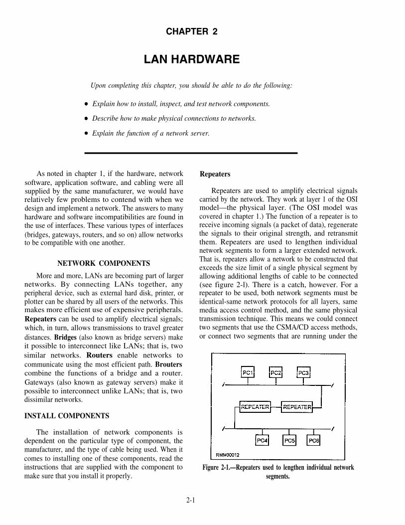
CHAPTER 2
LAN HARDWARE
Upon completing this chapter, you should be able to do the following:
Explain how to install, inspect, and test network components.
Describe how to make physical connections to networks.
Explain the function of a network server.
As noted in chapter 1, if the hardware, networksoftware, application software, and cabling were allsupplied by the same manufacturer, we would haverelatively few problems to contend with when wedesign and implement a network. The answers to manyhardware and software incompatibilities are found inthe use of interfaces. These various types of interfaces(bridges, gateways, routers, and so on) allow networksto be compatible with one another.
NETWORK COMPONENTS
More and more, LANs are becoming part of largernetworks. By connecting LANs together, anyperipheral device, such as external hard disk, printer, orplotter can be shared by all users of the networks. Thismakes more efficient use of expensive peripherals.Repeaters can be used to amplify electrical signals;which, in turn, allows transmissions to travel greaterdistances. Bridges (also known as bridge servers) makeit possible to interconnect like LANs; that is, twosimilar networks. Routers enable networks tocommunicate using the most efficient path. Brouterscombine the functions of a bridge and a router.Gateways (also known as gateway servers) make itpossible to interconnect unlike LANs; that is, twodissimilar networks.
INSTALL COMPONENTS
The installation of network components isdependent on the particular type of component, themanufacturer, and the type of cable being used. When itcomes to installing one of these components, read theinstructions that are supplied with the component tomake sure that you install it properly.
Repeaters
Repeaters are used to amplify electrical signalscarried by the network. They work at layer 1 of the OSImodel—the physical layer. (The OSI model wascovered in chapter 1.) The function of a repeater is toreceive incoming signals (a packet of data), regeneratethe signals to their original strength, and retransmitthem. Repeaters are used to lengthen individualnetwork segments to form a larger extended network.That is, repeaters allow a network to be constructed thatexceeds the size limit of a single physical segment byallowing additional lengths of cable to be connected(see figure 2-l). There is a catch, however. For arepeater to be used, both network segments must beidentical-same network protocols for all layers, samemedia access control method, and the same physicaltransmission technique. This means we could connecttwo segments that use the CSMA/CD access methods,or connect two segments that are running under the
Figure 2-1.—Repeaters used to lengthen individual networksegments.
2-1

token-passing access method. However, we cannotconnect a CSMA/CD segment to a token-passingsegment.
Bridges
Bridges handle the first two layers of the OSImodel—the physical layer and the data link layer. Likerepeaters, bridges connect physically-isolated networksto forma single logical network; however, a bridge has alittle more intelligence and can provide sometranslation between dissimilar protocols. For example,our token-passing segment wants to communicate withour CSMA/CD segment. The bridge will “repackage”the message from the token-passing segment into aformat that the CSMA/CD segment will understand.Then, the bridge will act as a workstation on theCSMA/CD segment and contend for access. The samething happens in reverse. A message is sent from theCSMA/CD segment to the token-passing segment. Thebridge then “repackages” the message into a format thetoken-passing segment is expecting and waits for thetoken, just like any other workstation. An importantpoint to remember is that a bridge will pass on anymessage it receives. Because the bridge is not smartenough to know that unlike LANs do not understandeach other, it will go ahead and send the message.Because the two LANs speak a different “language,”the message will be ignored.
Routers
Routers only connect networks running similaraccess methods. They work at the third layer of the OSImodel—the network layer. Like bridges and repeaters,routers can connect networks over different wiringmedia and topologies. However, unlike bridges, routerscan intelligently determine the most efficient path toany destination, based on predetermined delimiters.Routers are often a better choice for interconnectingremote installations and congested networks requiring asingle protocol. Let’s look at this more closely.
Let’s say we have a LAN made up of three token-passing segments, and each segment is connected via abridge. For a message to go from LAN A to LAN C, itwould have to travel through LAN A and LAN B beforeit reaches its final destination, which is LAN C. Seefigure 2-2, frame A. On a LAN that has large amountsof message traffic, we can see how a bridge may slowdown the system. On the other hand, if the segments areseparated by routers, the router on LAN A would look atthe destination of the message and determine the direct
route to LAN C that would be shortest route, asshown in figure 2-2, frame B.
Brouters
A brouter can work in either the second and thirdlayers of the OSI model—the data link layer or thenetwork layer. A brouter is a combination of a bridgeand router combined. If it can’t route a packet, it acts as abridge. Brouters are particularly useful if you have twoor more different networks. Working as a bridge, abrouter is protocol independent and can be used to filterlocal are a network traffic. Working as a router, abrouter is capable of routing packets across networks.
Gateways
Gateways work at OSI model layer 7—theapplication layer. A gateway functions to reconciledifferences between two dissimilar networks.Messages are not only repackaged for transmissionbetween different networks (CSMA/CD to token-passing), but the contents of the messages are convertedinto a format the destination can use and understand.Now our unlike LANs can talk to each other. Gatewayscan also provide links between microcomputernetworks and mainframes.
A gateway is generally a dedicated computer withan interface card and at least some type of software forboth of the environments being connected. Thegateway then runs special software that provides thenecessary conversion and translation services which, inturn, allow the two environments to communicate.
Figure 2-2.—Interconnecting LANS using (A) bridges and (B)routers.
2-2

Concentrators
The main function of a concentrator is to serve as atermination point for cable running from individualnodes in a network. The cable connects to the networkor to another wire center.
A concentrator may have multiple boards or boxesmounted on a rack. Each board is essentially a hub, awiring center for a single network’s nodes. Such boardsgenerally include light-emitting diodes (LEDs) toindicate the status of each port on the board.
Hubs
A hub is a box with a number of connectors to whichmultiple nodes (PCs) are attached. It serves as acommon termination point that can relay signals alongthe appropriate paths. All hubs provide connectivity,and some even provide management capabilities. A hubusually connects nodes that have a commonarchitecture. Although the boundary betweenconcentrators and hubs is not always clear, hubs aregenerally simpler and cheaper than concentrators.
Modems
In module 2, we introduced you to modems andhow they are used in a data communicationsenvironment. They translate data from digital to analogform at the sending end of the communications path andfrom analog to digital at the receiving end. From aconceptual standpoint, this explanation is sufficient.However, if you are going to install a modem, you need
MODEMS AT WORK.— Put simply, the object ofa modem is to change the characteristics of a simple sinewave, referred to as a carrier signal. We know thiscarrier signal has several properties that can be alteredto represent data. It has amplitude (height); it hasfrequency (a unit of time); and it has phase (a relativestarting point). Modems are capable of altering one ormore of these characteristics to represent data.
The job a modem performs can be divided into twodiscrete parts or phases at each end of thecommunications link. At the sending end, it convertsdigital bit streams (strings of 0’s and 1’s) into analog sinewaves. This is the encoding process. Anothercomponent within the modem then changes(modulates) the analog signal so the data may betransmitted simultaneously with other data and voicetraffic that has also been modulated. This process isbasically reversed at the receiving end. There, theanalog signal is brought back to its basic level(demodulated), and the analog sine waves arereconverted (decoded) back into their corresponding bitstreams (see figure 2-3).
CODECs.— In today’s digital communicationslines, voice traffic is considered the outsider that digitaldata used to be to analog lines. Voice can enter the datacommunications lines only after being encoded intodigital form. It then must be decoded to be audible againat the receiving end. The device used to perform theencoding and decoding functions is known as a codec.This is simply another black box conversion device thathas always been in existence in a slightly different form
to know some of the technical aspects of modems. as part of a modem.
Figure 2-3.—Digital data as it is encoded, modulated, transmitted, demodulated, and decoded.
2-3

Network Interface Card and Cabling
To attach personal computers to the LAN, you mustinstall a network interface card (NIC) into an emptyexpansion slot in the PC, install the appropriatesoftware, and attach the network cable to the NIC. Theother item you need to consider is what type ofconnector to use. But before deciding the type ofconnector to use, you need to know what type of cableand architecture you will be using. The cables may betwisted-pair cable, fiber optic cable, or coaxial cable.
Twisted-pair cable The twisted-pair cable iseasy to install and costs little on a per-foot basis. Insome cases existing telephone cable may be used. Itsdisadvantages include limitations in capacity andspeed. It is also susceptible to electrical interferenceunless it is shielded.
Fiber optic cable Fiber optic cable is the bestchoice if a secure network is needed. Because the cabletransmits light, the transmissions are immune tointerference caused by electrical or electronic devices.Also, if your network will run through an area of heavyindustrial activity or a work place with strong radiofrequency interference, fiber optic cable is the mostappropriate choice. Other advantages of the fiberopticcable are that it lasts longer than other cable and cancarry many more channels. Its disadvantages include itshigh price, poor connectivity, and low flexibility.
Coaxial cable Coaxial cable, also called coax,networks have gained in popularity because of their usein cable television. The quantities of cable andconnectors produced for cable television have greatlyreduced the prices of these components for networkusers. Coaxial cable comes in various thicknesses andis designated by a number: RG-11, RG-58, RG-59,RG-62, etc. You can use either baseband or broadbandtransmission methods with coaxial cable.
Baseband coaxial systems, which transmit digitalsignals unchanged over a single channel, have severaladvantages. They are inexpensive, simple, easy toinstall, and have low maintenance. They also allowvery high data transmission rates. One disadvantage isthey are limited to transmitting digital signals only.
In contrast, broadband coaxial systems requirethe digital signal to be converted to an analog signalbefore transmission and then back to digital by modemat the receiving device. Broadband systems supportdata, voice, and video signals that may be transmittedsimultaneously. Disadvantages of broadband systems
are their higher installation costs and complexmaintenance.
Connectors
The connector provides the physical link betweentwo components. For example, a connector can link acable and a NIC, a cable and a transceiver, or two cablesegments.
Connectors differ in their shape, size, gender,connection mechanism, and function. These featuresinfluence and determine where a connector can be used.Where necessary, special adapters may be used forconnections involving different connectorcombinations.
Connectors also differ in how sturdy they are, howeasily and how often they can be attached and detached,and in how much signal loss there is at the connectionpoint.
The type of connector needed in a particularsituation depends on the components involved and, fornetworks, on the type of cable and architecture beingused.
CONNECTOR FUNCTIONS.— A connectormay be passing the signal along or absorbing it. Aconnector that passes a signal along may pass itunmodified or may clean and boost it. Connectors canserve a variety of purposes, including the following:
Connect equal components, such as twosegments of thin coaxial cable
Connect almost equal components, such as thinto thick coaxial cable
Connect unequal components, such as coaxial totwisted-pair cable
Connect complementary components, such as aNIC to a network
Terminate a segment
CONNECTOR SHAPES.— Specially shapedconnectors are used for particular types of connectionsor for connections in particular locations. For example,a T-connector attaches a device to a cable segment; anelbow connector allows wiring to meet in a corner or at awall.
2 - 4

Figure 2-4.—Connector shapes.
Table 2-1.—Cable connector shapes.
The connector shapes used in networking setups arelisted in table 2-1. Figure 2-4 shows examples ofconnector shapes.
FIBER-OPTIC CONNECTORS.— Likeelectrical cable connectors, different types of fiber-optic connectors have different kinds of attachmentmechanisms. The actual attachments between ferruleshells may be made by threading, snapping, or clicking.Table 2-2 lists the most commons types of fiber-opticconnectors.
Table 2-2.—Fiber-optic connectors.
In addition to attachment mechanisms, fiber-optic
connectors differ in the following ways:
The size of the ferrule.
Whether the connector can be keyed. This is thetechnique for making a connector asymmetrical,usually by adding a notch or plug, making itimpossible to plug the connector in wrong.
The number of matings the connectors canhandle without producing unacceptable signalloss.
2-5

Whether the fiber must be twisted to make the INSPECTING COMPONENTS
connection; multiple fibers cannot run throughthe same connector if it is to be twisted.
The connectors differ in the way the fiber isattached to the connector itself. You can either useepoxy to glue the fiber into the connector, or you cancrimp the connector and the ferrule together using aspecial crimping tool.
CONNECTOR GENDERS.— Connector genderbasically refers to whether a connector has plugs orsockets. The gender is important because the elementsbeing connected must have complementary genders.
A male connector is known as a plug; the femaleconnector is known as a jack. With a few exceptions,such as the IBM® data connectors and certain fiber-optic connectors, all connector types have distinctgenders. Figure 2-5 shows examples of male andfemale connectors.
CONNECTOR MECHANISMS.— Theconnection mechanism defines how the physicalcontact is made to allow the signal to pass from one sideof the connection to the other.
Connection mechanisms differ in how sturdy theyare. For example, the pin-and-socket connection at aserial port can be wobbly without extra support from thescrews on either side of the plug. On the other hand,fiber-optic connectors must be cut to preciseproportions and must not allow any play in theconnection.
The inspection of the components when they arereceived is limited to checking for any physical damage.This damage will include:
Any damage to the packing material
Damage to the case
Hidden damage on the inside of the cabinet
The inspection that is conducted needs to be asthorough as possible, since any damage discoveredmust be reported to the supplier. This inspection alsoneeds to be accomplished as soon as the equipmentarrives, because the longer you wait, the less likely itbecomes that the supplier will replace the equipment.
NETWORK TESTING
Network testing is changing significantly becauseof the growth of digital network capability. Testing inthe voice network has always been considered as muchof an art as a science because of the variable nature ofthe different impairments encountered. The digitalnet work has been designed with more diagnosticcapability, making it much easier to identify and isolateproblems. The testing is done in the carrierenvironment, not in the user environment.
Network Testing Methods
There are three basic approaches to network testing,as follows:
Figure 2-5.—Connector genders.
2-6

1. Rely on vendors. If you rely on a vendor fortesting, you probably have a single vendor’s products inyour network and are, therefore, locked into that vendor.Fewer vendors today are capable of providing thiscomplete capability.
2. Use an organization dedicated to networkproblem solving (third party). At one time, third-partyproblem solving was considered a viable alternative,but today the expertise needed is so vast and covers sucha wide variety of products that it is not feasible toprovide the service. The carrier providing the majorityof your circuits is the best for handling your networkmanagement. However, it is difficult for the carrier tobe objective, and it is usually not very cost effective.
3. Use in-house network management. In-housenetwork control is by far the most flexible in design andoperation. Network administrators typicallyunderstand their problems better than any carrier orvendor could. Network problems are not always theresult of network conditions; they may actually beoperational problems. A disadvantage of in-housenetwork control is that it requires more resources, suchas knowledgeable people, equipment, space, and all ofthe other support overhead.
Regardless of the testing method that is used,testing can be performed by both hardware tools andsoftware programs.
Hardware Testing
The tools used are partly insurance and partlyconvenience devices. The greatest expense of anetwork comes when it is down or functioningincorrectly; it is important to be able to test componentswhen things go wrong. Testing should also beaccomplished before installing, to ensure that you donot install a faulty component. After they are installed,test components periodically to make sure they arefunctioning properly. Special tool are available for thispurpose.
Network testers can be very expensive, whileconvenience tools, such as wire crimpers andvoltmeters, are quite inexpensive. The amount that isspent on tools will depend on the size of the network, theimportance of the network’s contents, and who will bedoing the maintenance on the network.
The following are several types of hardware tools:
Manufacturing tools for creating individualcomponents, such as crimpers and dies forattaching wires to connectors.
Construction tools for assembling anddisassembling systems; for example,screwdrivers, pliers, chip removers, and chipinstallers.
Testing tools for testing individual componentsor for monitoring the performance of acomponent or system, such as voltmeters,ammeters, and line scanners.
Safety tools for making sure components areprotected against damage from electrical andother dangers; for example, static cords,electrical mats, and shorting probes.
BASIC TOOLS.— The level and range of toolsyou will need depends on the level of your involvementwith the network. Regardless of the level, a few basictools will almost certainly make your life easier:
Screwdrivers, for opening machines, installingand removing expansion cards, and for attachingconnectors;
Pliers, for grasping objects;
Wrenches or nut drivers, for tightening andloosening nuts;
Chip removers/installers, for removing andinstalling computer chips; and
Tweezers, for retrieving small parts and screws.
In addition to these tools, some people might alsohave wire strippers, cutters, and soldering irons that canbe used to set up special-purpose circuits or wiringconnectors.
If you are going to do any troubleshooting at all, youwill need a voltmeter or ammeter (probably both), withan operator’s manual, to test the electrical activity. Useof the manual is essential to connect the meter properly;connecting the meter wrong can cause serious damageto sensitive circuitry.
T O O L S F O R I N S T A L L I N G A N DATTACHING CABLE.— The tools used in makingcables are specialized tools. They are used to attach theconnectors onto the cable and then to test the cable. It isadvisable to get the cables pre-made to the desiredlength by the manufacturer. Unfortunately, that isn’talways possible.
To attach connectors to cable, you need thefollowing tools:
2-7
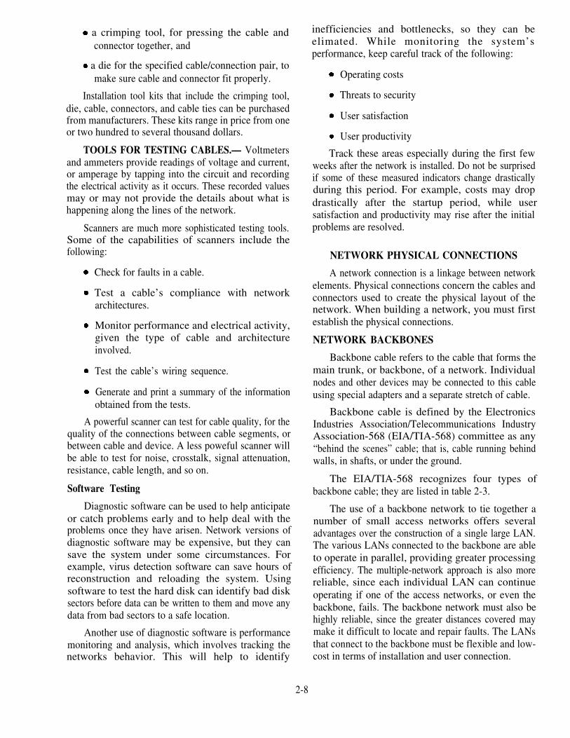
a crimping tool, for pressing the cable andconnector together, and
a die for the specified cable/connection pair, tomake sure cable and connector fit properly.
Installation tool kits that include the crimping tool,die, cable, connectors, and cable ties can be purchasedfrom manufacturers. These kits range in price from oneor two hundred to several thousand dollars.
TOOLS FOR TESTING CABLES.— Voltmetersand ammeters provide readings of voltage and current,or amperage by tapping into the circuit and recordingthe electrical activity as it occurs. These recorded valuesmay or may not provide the details about what ishappening along the lines of the network.
Scanners are much more sophisticated testing tools.Some of the capabilities of scanners include thefollowing:
Check for faults in a cable.
Test a cable’s compliance with networkarchitectures.
Monitor performance and electrical activity,given the type of cable and architectureinvolved.
Test the cable’s wiring sequence.
Generate and print a summary of the informationobtained from the tests.
A powerful scanner can test for cable quality, for thequality of the connections between cable segments, orbetween cable and device. A less poweful scanner willbe able to test for noise, crosstalk, signal attenuation,resistance, cable length, and so on.
Software Testing
Diagnostic software can be used to help anticipateor catch problems early and to help deal with theproblems once they have arisen. Network versions ofdiagnostic software may be expensive, but they cansave the system under some circumstances. Forexample, virus detection software can save hours ofreconstruction and reloading the system. Usingsoftware to test the hard disk can identify bad disksectors before data can be written to them and move anydata from bad sectors to a safe location.
Another use of diagnostic software is performancemonitoring and analysis, which involves tracking thenetworks behavior. This will help to identify
2-8
inefficiencies and bottlenecks, so they can beelimated. While monitoring the system’sperformance, keep careful track of the following:
Operating costs
Threats to security
User satisfaction
User productivity
Track these areas especially during the first fewweeks after the network is installed. Do not be surprisedif some of these measured indicators change drasticallyduring this period. For example, costs may dropdrastically after the startup period, while usersatisfaction and productivity may rise after the initialproblems are resolved.
NETWORK PHYSICAL CONNECTIONS
A network connection is a linkage between networkelements. Physical connections concern the cables andconnectors used to create the physical layout of thenetwork. When building a network, you must firstestablish the physical connections.
NETWORK BACKBONES
Backbone cable refers to the cable that forms themain trunk, or backbone, of a network. Individualnodes and other devices may be connected to this cableusing special adapters and a separate stretch of cable.
Backbone cable is defined by the ElectronicsIndustries Association/Telecommunications IndustryAssociation-568 (EIA/TIA-568) committee as any“behind the scenes” cable; that is, cable running behindwalls, in shafts, or under the ground.
The EIA/TIA-568 recognizes four types ofbackbone cable; they are listed in table 2-3.
The use of a backbone network to tie together anumber of small access networks offers severaladvantages over the construction of a single large LAN.The various LANs connected to the backbone are ableto operate in parallel, providing greater processingefficiency. The multiple-network approach is also morereliable, since each individual LAN can continueoperating if one of the access networks, or even thebackbone, fails. The backbone network must also behighly reliable, since the greater distances covered maymake it difficult to locate and repair faults. The LANsthat connect to the backbone must be flexible and low-cost in terms of installation and user connection.
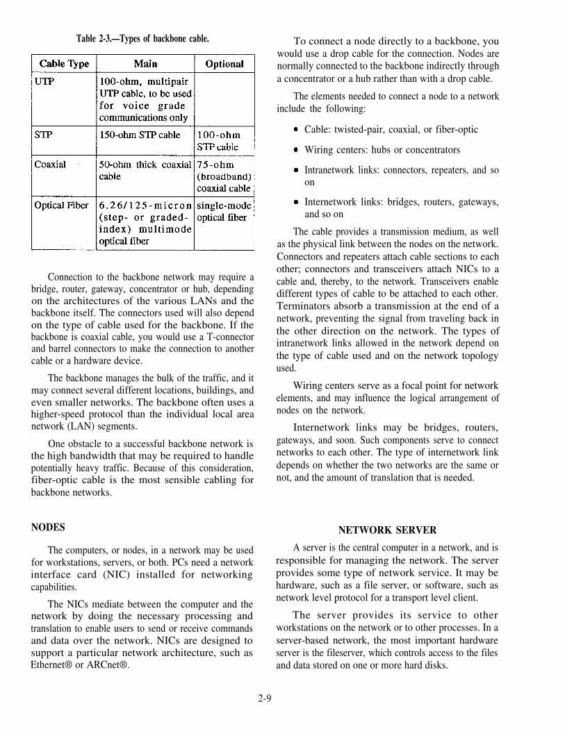
Table 2-3.—Types of backbone cable.
Connection to the backbone network may require abridge, router, gateway, concentrator or hub, dependingon the architectures of the various LANs and thebackbone itself. The connectors used will also dependon the type of cable used for the backbone. If thebackbone is coaxial cable, you would use a T-connectorand barrel connectors to make the connection to anothercable or a hardware device.
The backbone manages the bulk of the traffic, and itmay connect several different locations, buildings, andeven smaller networks. The backbone often uses ahigher-speed protocol than the individual local areanetwork (LAN) segments.
One obstacle to a successful backbone network isthe high bandwidth that may be required to handlepotentially heavy traffic. Because of this consideration,fiber-optic cable is the most sensible cabling forbackbone networks.
NODES
The computers, or nodes, in a network may be usedfor workstations, servers, or both. PCs need a networkinterface card (NIC) installed for networkingcapabilities.
The NICs mediate between the computer and thenetwork by doing the necessary processing andtranslation to enable users to send or receive commandsand data over the network. NICs are designed tosupport a particular network architecture, such asEthernet® or ARCnet®.
To connect a node directly to a backbone, youwould use a drop cable for the connection. Nodes arenormally connected to the backbone indirectly througha concentrator or a hub rather than with a drop cable.
The elements needed to connect a node to a networkinclude the following:
Cable: twisted-pair, coaxial, or fiber-optic
Wiring centers: hubs or concentrators
Intranetwork links: connectors, repeaters, and soon
Internetwork links: bridges, routers, gateways,and so on
The cable provides a transmission medium, as wellas the physical link between the nodes on the network.Connectors and repeaters attach cable sections to eachother; connectors and transceivers attach NICs to acable and, thereby, to the network. Transceivers enabledifferent types of cable to be attached to each other.Terminators absorb a transmission at the end of anetwork, preventing the signal from traveling back inthe other direction on the network. The types ofintranetwork links allowed in the network depend onthe type of cable used and on the network topologyused.
Wiring centers serve as a focal point for networkelements, and may influence the logical arrangement ofnodes on the network.
Internetwork links may be bridges, routers,gateways, and soon. Such components serve to connectnetworks to each other. The type of internetwork linkdepends on whether the two networks are the same ornot, and the amount of translation that is needed.
NETWORK SERVER
A server is the central computer in a network, and isresponsible for managing the network. The serverprovides some type of network service. It may behardware, such as a file server, or software, such asnetwork level protocol for a transport level client.
The server provides its service to otherworkstations on the network or to other processes. In aserver-based network, the most important hardwareserver is the fileserver, which controls access to the filesand data stored on one or more hard disks.
2-9

A server may be dedicated or nondedicated.Dedicated servers are used only as a server, not as aworkstation. Nondedicated servers are used both as aserver and a workstation. Networks with a dedicatedserver are known as server-based networks; those withnondedicated servers are known as peer-to peernetworks.
DEDICATED SERVERS
Dedicated servers cannot be used for ordinarywork. In fact, access to the server is often limited toprevent any access by unauthorized users.
Most of the high-end network packages assume youare using a dedicated server. If the network has adedicated server, it is most likely a file server.
A dedicated fileserver runs the NOS software, andworkstations run smaller programs whose function is todirect user commands to the workstation’s operatingsystem or to the server. Both servers and workstationsneed NICs to function on the network.
NONDEDICATED SERVERS
A nondedicated server can be used as a workstationas well as a server. Using a server as a workstation hasseveral disadvantages and is not advisable for largernetworks.
The following are disadvantages of nondedicatedservers as compared to dedicated servers:
2-10
Many of the NOSs that allow the nondedicatedserver to run with DOS make them extremelyslow and clumsy. While most dedicated servershave software that replaces DOS, such systemsmay also require a separate non-DOS partitionon the hard disk. This allows the NOS to arrangeand deal with the contents of the partition in away that optimizes performance.
Running applications on a DOS machine while itis also supposed to be running a network can leadto a deadly performance degradation.
Certain tasks will tie up a DOS machine,effectively stopping the network until the task isfinished.
Adequate security is more difficult to maintainon a nondedicated server.
SUMMARY
In this chapter we discussed the different types ofnetwork components and their functions. We describedcabling and the connectors used to connect the networkhardware. We covered the purpose of the server and thedifferences between a dedicated and a nondedicatedserver. Remember, the driving factor for the type ofhardware and cabling used is the topology of thenetwork.
CHAPTER 3
NETWORK TROUBLESHOOTING
Upon completing this chapter, you should be able to do the following:
Describe how to diagnose and isolate problems with LANs.
Describe how to troubleshoot network malfunctions.
Explain how to test and evaluate the connection of networking system nodes.
Explain how to troubleshoot communications line problems.
With any network system, you should have a set oferror procedures for personnel to follow to handle errorsor malfunctions on the system. These error proceduresare the steps to be taken when the system is notoperating properly. They are different from the error-detection and diagnostic procedures used to isolate andcorrect transmission problems.
A complete set of diagnostic procedures isnecessary for the system. The system procedures areused to isolate the problem to the system or subsystemlevel. Since the facilities of a network may not be in thelocal area, it is necessary to have a set of test softwareand equipment with replacement components availablefor diagnosing and correcting problems.
TROUBLESHOOTING LANS
As a communications specialist, more than likelyyou will be expected to know how to troubleshootproblems on LANs. As a troubleshooter, you must beable to identify a wide range of network problemsrelating to hardware (the data terminal equipment, thecommunications link, repeaters, gateways, and so on),software (network operating system, applications, andsoon), and peopleware (the end user). It will be your jobto identify, isolate, and resolve both the simple andcomplex problems.
DIAGNOSTIC TOOLS
Normally, a problem can be solved without toomuch difficulty with the help of diagnostic tools. Thebest diagnostic tool available is accuratedocumentation. This documentation should include:
Workstation and server configurations
All network related software and equipment
Location and paths of all wiring
Updated records of all equipment andconfigurations changes
With documentation in hand, along with the help ofdiagnostic software (a network management package ora LAN analyzer), and specialized diagnosticequipment, such as a datascope, a time domainreflectometer (TDR), or a breakout box, the jobbecomes routine.
Classifying the problems and taking the necessaryactions to resolve them are an important part of your jobas a troubleshooter. However, it is equally important toremember to log all problems according to youractivity’s procedures. This will identify recurringproblems, provide information for long term solutions,and enhance your command’s training program.
ISOLATING PROBLEMS
When isolating a problem, consider the three majorareas we discussed earlier-the user, the software, andthe hardware, usually in that order. The majority of allnetwork-related problems are caused by the user’sactions—operator errors. Users either do notunderstand how to operate their PC in a networkingenvironment or they are unfamiliar with the applicationsoftware package they are using. Most of the time youwill find yourself responding to user problems andcomplaints. A user will call, saying such things as thefollowing:
3-1
My terminal/PC is hung up, and I cannot get intothe system.
My terminal/PC screen suddenly went blank.
My temninal/PC keeps coming up with the sameerror message.
My terminal/PC will not allow me to access thedisk file.
My terminal/PC will not print.
It will be your job to determine if the problem isuser, software, or hardware related. Whenever youreceive a call about a problem, obtain as muchinformation as possible about the person and theproblem. Ask the user’s name, phone number, theterminal/PC or node identification number, the natureof the problem, and what, if anything, occurredimmediately preceding the problem. In addition, youshould ask the user what application he or she wastrying to access or currently working with at the time theproblem occured. Ask whether other users areexperiencing the same or similar problem, did any errormessages appear on the screen, and be sure to askwhether the PC was moved before the problemoccured. Sometimes moving hardware createsproblems—the connector cable may not be seatedproperly.
Once you have received initial information about aproblem, it should help you to categorize the problem.Keep in mind most problems are the result ofinexperienced users/operators. Because so manydifferent types of errors can occur, it would beimpossible for us to list them all, along with thenecessary steps to resolve them. However, based onpast experiences, we can provide you with some helpfulhints and guidelines to follow. If the problem seems tobe isolated to one user, it is probably user error; if theproblem occurs with a group of users in a commongeographic location, the problem is usually related tothe cable; and if the problem is network wide, a closelook at the network software is in order. Let us take alook at some of the more common problems thatfrequently occur and their solutions in connection withthese three categories.
PO3 Frost has just called to report he cannot log onto the LAN. You begin solving the problem by askingsome preliminary questions. You find this is the firsttime PO3 Frost has used the LAN and no one else in hisarea is experiencing any problems. At this point, youshould be able to recognize the problem is more than
likely the result of an inexperienced operator (usererror). The logical corrective action to take is to walkPO3 Frost through the proper log-on procedures andpassword security requirements. He follows yourinstructions and successfully logs onto the LAN. PO3Frost should have been able to log onto the LAN byfollowing the User’s Guide on LAN operations. Youmight want to review the guide to make sure it is currentand available to all users.
A few weeks later PO3 Frost calls again and reportshe has been having intermittent problems while loggedon to the LAN. Sometimes while he is saving orretrieving data, his machine locks up for no apparentreason. Again, no one in his immediate work area isexperiencing problems. After obtaining all thepertinent information available, you believe theproblem is faulty hardware. During the save andretrieve operations, a packet is generated and sentthrough the network interface card, onto the cable, andto its destination. So the two most logical componentsto check are the cable connections and the networkinterface card. The diagnostic tools to use are the timedomain reflectometer (TDR) to check any breaks on thecable and the diagnostics that come with the interfacecard. PO3 Frost runs the card diagnostics at the terminalwhile you check the cable continuity. The network cardpasses the test, but the TDR detects a continuity breaknear his location. A LAN technician checks theconnectors at the workstation and discovers one of theconnectors has worked itself loose. After replacing theconnector, the cable is tested again and passes. PO3Frost logs on to the LAN and experiences no furtherproblems. In this example we eliminated the cable itselfbecause no other user on the cable segment wasexperiencing problems. Had there been other users alsoexperiencing intermittent failures, then the cable wouldhave immediately been our focal point of testing, sincethis is the commonality between the users.
You arrive at work Tuesday morning and find astack of messages waiting for you from usersexperiencing problems while trying to access the wordprocessing program on the LAN. The only thing theseusers have in common is they all use the same fileserver. Immediately you focus your attention on thenetwork operating system and software. You call PO3Door to ask her a few questions before you begintroubleshooting any further. You learn PO3 Door is ableto access all application programs on the LAN with theexception of the word processing program. Youimmediately log on to the network managementprogram and monitor the data traffic. You discover nouser has used the word processing program since
3-2

Monday at 1600. The only person authorized to use theLAN after 1600 is PO1 Brush, who is the networkadministrator. You call PO1 Brush and ask if anychanges were made to the word processing programsince yesterday. PO1 Brush states he installed a newversion of the word processing program on Mondayaround 2200 to eliminate any work disruptions. You askhim to check the security access to this new version.You find PO1 Brush inadvertently restricted all usersfrom accessing the new version of the word processingprogram after he removed the old one. He makes thenecessary access changes, and everybody is once againhappy and able to use the new version.
As you can see, there is a pattern to the various typesof errors/problems you will encounter. The problemsyou will be confronted with will range from the simpleto the disastrous. They may be user/operator errors,software problems, or hardware malfunctions.Knowing which is sometimes easy. Under otherconditions, it may be difficult for you to determine thesource of the problem. The important thing is to learnfrom your past experiences. Keep a list of symptoms,probable causes, and ways you can use to trace aproblem to its cause. This will assist you in diagnosingand troubleshooting problems. You will also find usershave a tendency to make the same mistakes again andagain, especially while they are learning. You canprovide them a great service by explaining some of themore common problems they are likely to encounter,the reasons for the problems, and ways to avoid havingthem happen to them.
NETWORK MALFUNCTIONS
Any malfunction of the network is going to result ina nonavailability of the system to the users. Thediagnosis and fixing of this malfunction becomes a highpriority. There are three primary culprits to networkmalfunctions: component and server failures, and datacollisions.
COMPONENT FAILURE
Component failures are categorized in twocategories: hard faults and soft faults. Hard faults arerelatively easy to find, and a diagnostic program willdiagnose them correctly every time. Soft faults can bedifficult to find, because they occur sporadically or onlyunder specific circumstances, rather than every time thememory location is tested. A diagnostic program testscomputer hardware and peripheral devices for correctoperation.
Most computers run a simple set of system checkswhen the computer is turned on. The PC tests are storedin read-only memory (ROM), and are known as power-on self tests (POSTs). If a POST detects an errorcondition, the computer will stop and display an erroron the screen. Some computers will emit a beep signalto indicate the type of error.
One of the best tools to use for networkmalfunctions is a network analyzer. A network analyzeris a product that can be used to monitor the activity of anetwork and the stations on it, and to provide dailysummaries or long-term trends of network usage andperformance. A network analyzer can do tasks such as:
Count or filter network traffic.
Analyze network activity involving specifiedprotocols or frame structures.
Generate, display, and print statistics aboutnetwork activity, either as they are beinggenerated or in summary form.
Send alarms to a network supervisor or networkmanagement program if any of the statisticsbeing monitored exceeds predetermined limits.
Do trend or pattern analyses of network activity.
Network analyzers may be software only or consistof both software and hardware. The latter may includean interface card enabling you to test the networkdirectly. This card may include an on-board processor.Because of their greater capabilities, hardware/softwareanalyzers are more expensive than the software onlyanalyzers. In fact, the prices for the hardware/softwareanalyzers can be several times as high as those for thesoftware only versions.
SERVER FAILURE
The most obvious sign that the server has failed forsome reason is that all users, except root, will not be ableto logon to the system. Use the following steps asrequired to reestablish services:
The first and easiest thing to try is to run thesystem distribution again. This will rebuild thesystem maps if nothing else is wrong and willallow users access to the system.
Shutdown and reboot the system. During theboot process ensure that no failures occur on anyof the nodes.
3-3

Verify the domain name.
Look for the maps subdirectory; it should be thesame as the domain name. If it is not there, youwill need to run the system initializationcommand.
If the above fails, ensure that all the files to bemapped are present on the server. If any havebeen deleted, they will have to be restored fromthe latest system saves.
One of the best ways to avoid server malfunctions isto conduct maintenance on the server. It is important toset up a schedule for your server and strictly adhere to it.To check the hardware, you should do at least thefollowing things:
Clean the server carefully but thoroughly.
Check cabling and connections for tightness andsigns of bending or stress. Do not disconnectconnectors unless necessary, since manyconnectors are rated for a limited number ofmatings.
If possible, check the cabling with a lineanalyzer.
Run thorough diagnostics on the storage mediumand on other system components to identify thecomponents that are likely to fail and to deal withthese before they actually do fail.
Check the quality of your power line by using aline tester.
The hardest part of server maintenance is findingthe time to conduct the maintenance, since the networkwill have to be offline to conduct. In many cases, servermaintenance will need to be during off peak hours, latenight or early morning, when there is little or no use.
DATA COLLISIONS
A data collision is the simultaneous presence ofsignals from two nodes on the network. A collision canoccur when two nodes each think the network is idle andboth start transmitting at the same time. Both packetsinvolved in a collision are broken into fragments andmust be retransmitted.
Collision Detection
To detect for a collision, nodes check the dc voltageon the line. A voltage level of two or more times higher
3-4
than expected indicates a collision, since this meansthere are multiple signals traveling along the backboneat the same time.
In a CSMA/CD (carrier sense multiple access withcollision detection) systems, all workstations or nodesattached to the network monitor the transmissionmedium at all times. When a node needs to send data, itwaits until the line is quiet and then transmits. If two ormore nodes happen to transmit data at the same instant,a collision occurs. Each node detects the collision andthen waits for a variable amount of time (asprogrammed in the NIC’s microprocessor) beforetesting the bus again and retransmitting. Since eachnode waits for a different amount of time, say 10/1000and 20/1000 of a second, it is very unlikely that thecollision will occur a second time. The CSMA/CDdetection method is further illustrated in figure 3-1.
Collision Avoidance
To avoid collisions, nodes can send special signalsthat indicate a line is being used for a transmission. In a
Figure 3-1.—A bus network using the CSMA/CD accessmethod.

CSMA/CA (carrier sense multiple access with collisionavoidance) system, the media-access method uses RTS(ready to send) and CTS (clear to send) signals beforesending a frame onto the network. A node transmitsonly after the node has requested access to the line andaccess has been granted. Other nodes will be aware ofthe RTS/CTS transmission and will not try to transmit atthe same time.
RTS.— A hardware signal sent from a potentialtransmitter to a destination to indicate that thetransmitter wishes to begin a transmission. If thereceiver is ready, it sends a CTS signal in return.
CTS.— A hardware signal sent from a receiver to atransmitter to indicate that the transmitter can beginsending. ACTS signal is generally sent in response toan RTS signal from the transmitter.
NETWORK SYSTEM CONNECTIONS
The testing and evaluation of network connectionsis accomplished with the same test equipment that isused to test network components. This equipmentincludes voltmeters, ammeters, volt-ohm-milliammeters, and line scanners. All of this testequipment checks the voltage, resistance, and currentthat passes through the cable and the connectorsbetween the network nodes. Any increase or decrease involtage or current or an increase in the resistance willcause communications problems for the users.
Whether the cable is pre-made or you make it, youshould always test the cable before it installed into thenetwork. This will alleviate the possibility of installinga bad cable or connector to the system. Any time thatyou can detect a bad connector will be to youradvantage, since each connector has a limited numberof connections before it has to be replaced.
COMMUNICATION LINE PROBLEMS
Communication line problems fall into threegeneral categories: excessive noise, cabling, andbackbone connections. With proper testing andprecautions, these problems can be taken care of beforethey happen.
EXCESSIVE NOISE
Noise is the term for random electrical signals thatbecome part of a transmission, and that serve to makethe signal (information) component of the transmissionmore difficult to identify. Noise can take various forms,including the following:
Impulse noise: voltage increases that last for justa short period, usually for only a fewmilliseconds.
White noise: random background noise.
Crosstalk: interference on one wire fromanother.
There are limits set on the allowable levels for eachof these types of noise. A noise filter can be used toremove random noise from a signal.
In a transmission, signal-to-noise ratio (SNR) is theratio between the signal and noise levels at a givenpoint, usually at the receiving end of the transmission.The SNR value is generally expressed in dB.
The SNR can be used to determine how long a cablesegment can be before the signal loss is unacceptablyhigh. The SNR also helps to determine whether aparticular type of cable will work for the intended use.Cable testers can help determine whether a particulartype of cable is appropriate in a specific environment.
In general, digital signals have a much higher SNRthan analog signals. Because analog signals in abroadband network must be confined to a portion of thetotal bandwidth, filtering and other signal-cleaningmeasures are necessary This confinement makes thesignal more delicate and subject to distortion.
Several types of filtering maybe used to help cleana broadband transmission. The filters are distinguishedby the filtering technique they use as well as by where inthe transmission process they are applied.
For example, filters applied early in thetransmission, prior to modulation, are known asbaseband or premodulation filters. Those applied afterthe modulation are known as passband orpostmodulation filters.
CABLING
Cables are good media for signals, but they are notperfect. The signal at the end of the cable should be asloud and clear as at the beginning, but this will not betrue.
Any transmission consists of signal and noiseconponents. Even a digital signal degrades whentransmitted over a wire. This is because the binaryinformation must be converted to electrical form fortransmission, and because the shape of the electricalsignal changes over distance.
3-5

Signal quality degrades for several reasons,including attenuation, crosstalk, and impedance.
Attenuation
Attenuation is the decrease in signal strength,measured in decibels (dB) per 100 feet. Such losshappens as the signal travels over the wire. Attenuationoccurs more quickly at higher frequencies and when thecable’s resistance is higher.
In networking environments, repeaters areresponsible for cleaning and boosting a signal beforepassing it on. Many devices are repeaters withoutexplicitly saying so. For example, each node in a token-ring network acts as a repeater. Since attenuation issensitive to frequency, some situations require the useof equalizers to boost different-frequency signals theappropriate amount.
Crosstalk
Crosstalk is interference in the form of a signal froma neighboring cable or circuit; for example, signals ondifferent pairs of twisted wires in a twisted pair cablemay interfere with each other. A commonly usedmeasure of this interference in twisted-pair cable isnear-end crosstalk (NEXT), which is represented in dB.The higher the dB value, the less crosstalk and the betteris the cable.
Additional shielding between the carrier wire andthe outside world is the most common way to decreasethe effects of crosstalk.
Impedance
Impedance, which is a measure of electricalresistance, is not directly a factor in a cable’sperformance. However, impedance can become afactor if it has different levels at different locations in anetwork. In order to minimize the disruptive effects ofdifferent impedances in a network, special devices,called baluns, are used to equalize impedance at theconnection.
Impedance does reflect performance indirectly.The higher the impedance, the higher is the resistance;the higher the resistance, the greater is the attenuation athigher frequencies.
Line Conditioning
Line conditioning tries to eliminate the effects ofcertain types of distortions on the signal. It becomes
3-6
more necessary as transmission speeds increase. Twotypes of line conditioning are available:
C conditioning tries to minimize the effects ofdistortion related to signal amplitude anddistortion due to envelope delay.
D conditioning tries to minimize the effects ofharmonic distortion in addition to the amplitudeand envelope delay distortions handled by type Cconditioning.
A line driver is a component that includes atransmitter and a receiver; it is used to extend thetransmission range between devices that are connecteddirectly to each other. In some cases a line driver can beused in place of a modem, for short distances of 10 milesor less.
To test a particular section of cable, you can use aline-testing tool. A line monitor is a low-end line-testing tool that tells you if the line is intact. A high-endline-testing tool can do very precise measurementsusing time domain reflectometry (TDR). A TDR is adevice used to test the integrity of a section of cablebefore the cable is even unwound. This diagnosticmethod uses a signal of a known amplitude andduration, which is sent along a stretch of cable.Depending on the amount of time the signal takes toreturn and on the cable’s nominal velocity ofpropagation, the TDR can determine the distance thesignal traveled and whether there are any shorts oropens in the cable.
BACKBONE CONNECTIONS
In addition to the inherent problems of the cabling,backbone connections add the problems that come withthe use of connectors. They have only a limited numberof times that they can be connected before they have tobe replaced. These connectors are used in severalplaces along the backbone, each presenting one moreplace for trouble to start. Some of the places thatconnectors are used are:
At the server
At the repeater, concentrator, and the gateway
Along the backbone for each drop or tap
At the splice and coupler (used with fiberoptic)
Each of the connections uses a different type ofconnector, each with its own limitations. For example:

A vampire tap is a connector that uses two prongsto pierce the cable to make its connection. Whenit is used, one of the prongs can be bent and notmake a proper connection.
An RJ connector is the same type of connectorused to plug your telephone into the wall. Whenit is used, the plastic clip has a tendency to breakoff the connector, resulting in the plug notlocking in place.
3-7
SUMMARY
In this chapter we discussed the how to troubleshootcommunications line problems, network malfunctions,and how to test and evaluate the connection ofnetworking sys tem nodes . As wi th anytroubleshooting, individual manufacturers of bothhardware and software will have their own techniquesto follow. What we have tried to do is give you a briefoverview of the type of trouble that you can expect torun into and some basics as how to begin thetroubleshooting.


APPENDIX I
GLOSSARY
A
ATTENUATION— Loss of communication signalenergy.
B
BASEBAND— The frequency band occupied byindividual information bearing signals before theyare combined with a carrier in the modulationprocess.
BISYNC— Controlling of data transmission by timingsignals generated at the sending and receivingstations.
BROADBAND— Transmission facilities whosebandwidth is greater than that available on voice-grade facilities.
BUS— Channel or path for transferring data andelectrical signals.
C
CARRIER SENSE MULTIPLE ACCESS(CSMA)— A protocol that controls access to anetwork’s bus.
CARRIER SENSE MULTIPLE ACCESS WITHCOLLISION AVOIDANCE (CSMA/CA)— Aprotocol that requires carrier sense and in which adata station that intends to transmit sends a jamsignal.
CARRIER SENSE MULTIPLE ACCESS WITHCOLLISION DETECTION (CSMA/CD)— Aprotocol that requires carrier sense and in which atransmitting data station that detects another signalwhile transmitting, stops sending, sends a jamsignal, and then waits for a variable time beforetrying again.
CLEAR TO SEND— A hardware signal sent from areceiver to a transmitter to indicate that thetransmitter can begin sending.
CROSSTALK— The disturbance caused in a circuit byan unwanted transfer of energy from anothercircuit.
F
FILTER— A device or program that separates data,signals, or material in accordance with specifiedcriteria.
FIREWALL— One or more components that controlthe flow of network traffic between networks.
H
HANDSHAKING— The process through which therules for exchanging data over a communicationsline are defined for the two devices involved.
I
IMPEDANCE— A measure of electrical resistance.
INTERNATIONAL STANDARDS ORGANIZA-TION (ISO)— The international agencyresponsible for developing standards forinformation exchange.
INTERRUPT REQUEST LINES— Physicalconnections between hardware devices and theinterrupt request.
L
LINE DRIVER— A component that includes atransmitter and a receiver.
LINK— The communications media used to connectnodes.
M
MULTITASKING— A mode of operation thatprovides for concurrent performance of two ormore tasks.
N
NETWORK INTERFACE CARD (NIC)— Theexpansion card that allows the workstation tocommunicate with the network.
AI-1
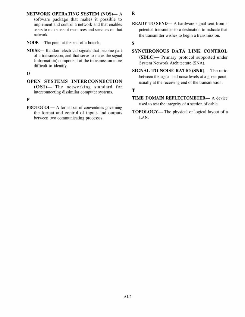
NETWORK OPERATING SYSTEM (NOS)— Asoftware package that makes it possible toimplement and control a network and that enablesusers to make use of resources and services on thatnetwork.
NODE— The point at the end of a branch.
NOISE— Random electrical signals that become partof a transmission, and that serve to make the signal(information) component of the transmission moredifficult to identify.
O
OPEN SYSTEMS INTERCONNECTION(OSI)— The networking standard forinterconnecting dissimilar computer systems.
P
PROTOCOL— A formal set of conventions governingthe format and control of inputs and outputsbetween two communicating processes.
R
READY TO SEND— A hardware signal sent from apotential transmitter to a destination to indicate thatthe transmitter wishes to begin a transmission.
S
SYNCHRONOUS DATA LINK CONTROL(SDLC)— Primary protocol supported underSystem Network Architecture (SNA).
SIGNAL-TO-NOISE RATIO (SNR)— The ratiobetween the signal and noise levels at a given point,usually at the receiving end of the transmission.
T
TIME DOMAIN REFLECTOMETER— A deviceused to test the integrity of a section of cable.
TOPOLOGY— The physical or logical layout of aLAN.
AI-2

APPENDIX II
GLOSSARY OF ACRONYMS ANDABBREVIATIONS
A
AWG— American wire gauge.
B
Bisync— Binary synchronous communicationsprotocol.
BNC— Barrel nut connector.
bps— Bits per second.
C
CAD— Computer aided design.
CODEC— Coder/decoder.
CSMA— Carrier sense multiple access.
CSMA/CA— Carrier sense multiple access withcollision avoidance.
CSMA/CD— Carrier sense multiple access withcollision detection.
CTS— Clear to send.
D
dB— Decibel.
E
EIA/TIA— Electronics Industries Association/Telecommunications Industry Association.
F
FSCK— Filesystem check.
FTP— File transfer protocol.
G
Gbps— Gigabits per second.
H
HTTP— Hypertext transfer protocol.
I
IP— Intemet protocol.
IRQ— Intermpt request line.
ISO— International Standards Organization.
L
LAN— Local area network
LED— Light-emitting diode.
M
MAN— Metropolitan area network.
MAU— Multistation access unit.
Mbps— Megabits per second.
MIC— Medium interface connector.
MODEM— Modulator-demodulator.
N
NEXT— Near-end crosstalk.
NIC— Network interface card.
NOS— Network operating system.
O
OSI— Open systems interconnection.
P
POST— Power-on self test.
R
RJ— Registered jack.
ROM— Read-only memory.
RTS— Ready to send.
S
SC— Subscriber connector.
SDLC— Synchronous data link control.
SMA— Sub-miniature assembly.
AII-1

SNR— Signal-to-noise ratio. TELNET— Telecommunications network.
ST— Straight tip. U
STP— Shielded twisted pair.UDP— User datagram protocol.
T UTP— Unshielded twisted pair.
TCP— Transmission control protocol. W
TDR— Time domain reflectometer.WAN— Wide area network.
AII-2

APPENDIX Ill
REFERENCES USED TODEVELOP THE TRAMAN
Feibel, Werner, Novell’s® Complete Encyclopedia of Networking, Sybex Inc.,Alameda, CA, 1995.
Gibbs, Mark, Absolute Beginner’s Guide to Networking, Second Edition, SamsPublishing, Indianapolis, IN 1995.
Liebing, Edward, NetWare User’s Guide, M & T Books, New York, NY, 1993.
Lowe, Doug, Networking For Dummies, IDG Books Worldwide, Inc., Foster City,CA, 1994.
Martin, James, Local Area Networks Architectures and Implementations, PrenticeHall, Englewood Cliffs, NJ, 1989.
Ported SNAP I/II System Administration Manual TAC-3 Version, NAVMASSODocument Number 54-94-1, Navy Management System Support Office,Chesapeake, VA, 1994.
Sherman, Ken, Data Communications User’s Guide, Third Edition, Prentice Hall,Englewood Cliffs, NJ, 1990.
AIII-1


INDEX
A D
Access methods, 1-12
contention, 1-12
network standards, 1-13
token passing, 1-13
Analyze configuration, 1-6
C
Cabling, 1-15, 3-5
cable selection, 1-17
coaxial, 1-16, 2-4 .excessive noise, 3-5
fiber optic, 1-17, 2-4
impedance, 3-6
line conditioning, 3-6
twisted-wire pairs, 1-16, 2-4
Coaxial, 1-16, 2-4
baseband, 2-4
broadband, 2-4
Collision avoidance, 3-4
CTS, 3-5
RTS, 3-5
Communication line problems, 3-5
attenuation, 3-6
backbone connections, 3-6
cabling, 3-5
Connectors, 2-4
function, 2-4
genders, 2-6
mechanisms, 2-6
shapes, 2-4
Crosstalk, 1-16, 3-6
Data collisions, 3-4
avoidance, 3-4
detection, 3-4
E
Excessive noise, 3-5
crosstalk, 3-5
impulse, 3-5
white, 3-5
F
Firewalls, 1-18
application layer, 1-18
choosing, 1-19
packet filters, 1-18
H
Hardware testing, 2-7
basic tools, 2-7
tools for installing cable, 2-7
tools for testing cables, 2-8
I
Install components, 2-1
bridges, 2-2
brouters, 2-2
concentrators, 2-3
connectors, 2-4
gateways, 2-2
hubs, 2-3
modems, 2-3
network interface card, 2-4
repeaters, 2-1
routers, 2-2
INDEX-1

L
LAN configurations, 1-9
bus, 1-10
distributed tree, 1-11
ring, 1-11
star, 1-9
Links, 1-1
M
Monitor, 1-3
N
Network analyzer, 3-3
Network components, 2-1
inspecting, 2-6
install, 2-1
testing, 2-6
Network configurations, 1-4
analyze configuration, 1-6
network parameters, 1-5
network port configuration, 1-5
software configurations, 1-5
system parameters, 1-4
system resource limits, 1-6
Network design, 1-9
access methods, 1-12
cabling, 1-15
calculating capacity, 1-9
firewalls, 1-18
LAN configurations, 1-9
network operating system, 1-18
operating system, 1-18
protocols, 1-12
requests, 1-9
Network malfunctions, 3-3
component failure, 3-3
data collision, 3-4
Network operations, 1-1
server failure, 3-3
monitor, 1-3
network startup/shutdown, 1-2
remote terminals, 1-2
review audit logs, 1-4
Network parameters, 1-5
modifying, 1-5
setting, 1-5
Network physical connections, 2-8
backbones, 2-8,3-6
nodes, 2-9
Network port configuration, 1-5
port address or name, 1-5
Network server, 2-9
dedicated, 2-10
nondedicated, 2-10
Network software, 1-6
application, 1-7
installation, 1-7
testing, 1-8
restoration, 1-8
system, 1-6
Network startup/shutdown, 1-2
system shutdown, 1-3
system startup, 1-2
Network testing, 2-6
hardware, 2-7, 3-5
methods, 2-6
software, 2-8
Nodes, 1-1
O
OSI model, 1-13
layer 1, 1-14
layer 2, 1-14
INDEX-2

OSI model—Continued
layer 3, 1-14
layer 4, 1-15
layer 5, 1-15
layer 6, 1-15
layer 7, 1-15
P
Protocols, 1-12
Bisync, 1-12
SDLC, 1-12
R
Reboot, 1-3
Remote Terminals, 1-2
logins, 1-2
remote console, 1-2
S
System modes, 1-3
multi-user, 1-3
single-user, 1-3
System parameters, 1-4
hardware interrupt, 1-4
software interrupt, 1-4
System resource limits, 1-6
hardware, 1-6
software, 1-6
System restoration, 1-8
reconfiguration, 1-8
redundancy, 1-8
rerouting, 1-8
T
Troubleshooting, 3-1
diagnostic tools, 3-1
isolating problems, 3-1
INDEX-3


Assignment Questions
Information: The text pages that you are to study areprovided at the beginning of the assignment questions.


ASSIGNMENT 1Textbook Assignment: “Network Administration,” chapter 1, pages 1-1 through
1-19.
1-1. Networking gives anindividual the capability tocommunicate and connect withanother individual oranother system in order toaccomplish which of thefollowing tasks?
1. Send messages2. Share resources3. Extend processing4. Perform multiprocessing
1-2. Which of the following typesof cables is NOT used forcommunications?
1. Coaxial2. Fiber optic3. Solid core4. Twisted-pair
1-3. Login procedures that areaccomplished by dialing intoan access server are knownby which of the followingterms?
1. Dialup access2. Distance access3. Extended access4. Remote access
1-4. The first thing that theinitialization programchecks is which of thefollowing areas?
1. Connections2. Memory3. Peripherals4. User accounts
1-5.
1-6.
1-7.
1-8.
What is the function of thekernel?
1. Establishescommunications
2. Initializes the system3. Mounts and initializes
system files4. Verifies the integrity
of the root filesystem
How many primary modes ofsystem operation are there?
1. One2. Two3. Three4. Four
Rebooting the system iscalled for in how manycommon situations?
1. Five2. Two3. Six4. Four
When shutting down thesystem, turning off thepower to the CPU isrecommended under which ofthe following times orconditions?
1. End of the day2. End of the week3. Normal conditions4. Emergency conditions
1

1-9. Which of the following isNOT a reason why you shouldmonitor the network?
1. To enable you to tuneyour network
2. To establishcommunications
3. To maintain aperformance history
4. To provide a statisticalbasis for equipmentpurchases
1-10. The main importance ofreviewing audit/event logsis which of the followingfunctions?
1. Check system throughput2. Monitor system
degradation3. Monitor system security4. Verify password attempts
1-11. By using the audit logs, anetwork administrator cantrack which of the followingareas?
1. Which files wereaccessed
2. When files were accessed3. Who accesed certain
files4. Each of the above
1-12. How many interrupt requestlines (IRQs) are there in aPC environment?
1-13.
1-14.
1-15.
1-16.
IRQ values for a device maybe set through software ormanually by which of thefollowing ways?
1. DIP switches2. Expansion slot3. Type of cable used4. Order in which device
was installed
Network performance isgoverned by which of thefollowing areas?
1. Administration2. Hardware3. Software4. Both 2 and 3 above
Besides a physical interfacebetween the device and thecomputer, what other type ofinterface does a portprovide?
1. Electrical2. Logical3. Parallel4. Transfer
Which of the following termsis used to describe theprocess used by anapplication to test a remotedevice?
1. Pinging2. Ringing3. Signaling4. Sounding
1. 142. 163. 184. 20
2

1-17.
1-18.
1-19.
1-20.
The interface between thetelecommunications accesssoftware and the applicationprograms is known by whichof the following terms?
1. Network operating system2. Network system software3. Telecommunications
access software4. Teleprocessing monitor
Electronic mail isclassified as what type ofsoftware program?
1. Communications2. Utility3. Network access4. Network operating
Which of the following termsdescribes the prevention offiles from being updated bymore than one user at atime?
1. Data integrity2. Data validity3. System access4. System security
access can be designated bywhich of the followingterms?
1. Private2. Public3. Shared4. Each of the above
1-21.
1-22.
1-23.
1-24.
Network software oftenprovides some type oflocking capability. Thislocking feature preventswhich of the followingactions?
1. Access to the file whileit is being worked on
2. Logging onto more thanone workstation at atime
3. Security violations fromoccurring
4. Unauthorized users fromlogging onto the network
Once the software isinstalled on the network, itmust be tested.
1. True2. False
How many methods are used toprovide service restorationafter system degradation?
1. Five2. Two3. Three4. Four
3
The different levels ofDELETED

1-25.
1-26.
1-27.
1-28.
1-29.
What is the minimum 1-30.percentage to be used incalculating the availableresources for the network?
1. 102. 153. 204. 25
How many major types of LANconfigurations are there? 1-31.
1. Five2. Six3. Three4. Four
Which of the followingtopologies was the earliesttype?
1. Bus2. Ring3. Star4. Distributed
Which of the followingtopologies permitscentralized diagnostics ofall functions?
1. Bus2. Ring3. Star4. Distributed
Which of the followingtopologies is used in manylow-cost LANs?
1. Bus2. Ring3. Star
1-32.
4. Distributed
4
1-33.
Which of the followingtopologies normally requiresthe entire network bebrought down to add a newnode?
1. Bus2. Ring3. Star4. Distributed
Which of the followingtopologies can be easilyadapted to the physicalarrangement of the facilitysite?
1.2.3.4.
BusRingStarDistributed
Which of the followingprotocols is/are used-tocontrol line discipline?
1. Asynchronous datacontrol
2. Binary synchronouscommunications
3. Synchronous data linkcontrol
4. Both 2 and 3 above
The access method that willbe used is governedprimarily by which of thefollowing factors?
1. Protocol2. Topology3. Both 1 and 24. Network operating system

1-34.
1-35.
1-36.
1-37.
Using the token passingaccess method, what, ifanything, happens when thetransmitting stationreceives the same token?
1.
2.
3.
4.
1.2.3.4.
The message is beingsentThe message has beenpassed around thenetworkThe message has beenappended by anotherstationNothing
How many layers are there inthe OSI reference model?
FiveSixSevenEight
The physical layer is whichlayer number of-the OSIreference model?
1. One2. Two3. Three4. Four
Which layer provideserror-free transmission ofinformation over thephysical medium?
1. Data link2. Network3. Physical4. Transport
1-38.
1-39.
1-40.
1-41.
1-42.
The network layer is whichlayer number of the OSIreference model?
1. One2. Two3. Three4. Four
The transport layer is whichlayer number of the OSIreference model?
1. Five2. Two3. Three4. Four
Which layer ensures dataunits are deliverederror-free, in sequence,with no losses orduplications?
1. Network2. Presentation3. Session4. Transport
Which layer performs thefunctions that enable twoapplications to communicateacross the network?
1. Network2. Presentation3. Session4. Transport
Which layer formats data tobe presented to theapplication layer?
1. Network2. Presentation3. Session4. Transport
5

1-43.
1-44.
1-45.
1-46.
Which layer represents theservices that directlysupport users?
1. Application2. Network3. Physical4. Session
Which of the following cabletypes is the leastexpensive?
1. Coaxial2. Fiber optic3. Solid core4. Twisted-pair
For network purposes, 22-and 24-gauge wire are themost common types of whichof the following types ofcables?
1. Coaxial2. Fiber optic3. Solid core4. Twisted-pair
Which of the following typesof cable can handle a dataflow of up to approximatelyone Mbps?
1. Coaxial2. Fiber optic3. Solid core4. Twisted-pair
1-47. Coaxial cable is usedextensively in LANs wheneverthe distance involved isrelatively short, generallyless than how many miles (a)for baseband and (b) forbroadband?
1. (a) 1 (b) 52. (a) 2 (b) 53. (a) 2 (b) 104. (a) 5 (b) 10
1-48.
1-49. Why is fiber optic cableimmune to electricalinterference of any kind?
1. Has only one strand percable
2. Has thick shielding3. Carries no electrical
current4. Uses double insulation
on each wire
1-50.
6
DELETED
DELETED

1-51.
1-52.
Firewalls can be dividedinto how many differentcategories?
1. Five2. Two3. Three4. Four
What piece of hardware is
1-53. Which of the followingfeatures can be provided bya firewall?
1. Address translation2. Authentication3. Virtual private networks4. All of the above
typically used to implementpacket filtering?
1. Bridge2. Gateway3. Hub4. Router
7

ASSIGNMENT 2Textbook Assignment: “LAN Hardware,” chapter 2, pages 2-1 through 2-10;
“Network Troubleshooting,” chapter 3, pages 3-1through 3-7.
2-1.
2-2.
2-3.
2-4.
2-5.
Which of the followingdevices is used to amplifyelectrical signals carriedby the network?
1. Bridge2. Gateway3. Repeater4. Router
Which of the followingdevices is used to connectidentical network segments?
1. Bridge2. Gateway3. Repeater4. Router
Which of the followingdevices handles the firsttwo layers of the OSI model?
1. Bridge2. Gateway3. Repeater4. Router
Which of the followingdevices works at the thirdlayer of the OSI model?
1. Bridge2. Gateway3. Repeater4. Router
Which of the followingdevices works at layer sevenof the OSI model?
1. Bridge2. Gateway3. Repeater4. Router
2-6. Which of the followingdevices serves as atermination point for acable running fromindividual nodes in anetwork?
1. Bridge2. Concentrator3. Gateway4. Hub
2-7. Which of the followingdevices is a box with anumber of connectors towhich multiple nodes areattached?
1. Bridge2. Concentrator3. Gateway4. Hub
2-8. Which of the followingfactors need to be decidedon before determining thetype of connector to use?
1. Architecture only2. Cable only3. Both architecture and
cable4. Environment
2-9. Which of the followingcables is the best choice ifa secure network is needed?
1. Coaxial2. Fiber optic3. Solid core4. Twisted-pair
8

2-10.
2-11.
2-12.
1.2.3.4.
2-13.
1.2.3.4.
2-14.
2-15.
Which of the followingcables is identified by adesignation number of RG-11?
1. Coaxial2. Fiber optic3. Solid core4. Twisted-pair
Which of the followingsignals is NOT supported bya broadband system?
1. Data2. Digital3. Video4. Voice
What type of connector isused to link two segments ofcable in a straight run?
BarrelElbowRJT
What type of connector isused to connect telephonesto the wall?
BarrelElbowRJT
An ST connector is rated forwhat number of matings?
1. 2002. 5003. 8004. 1000
An SC connector is rated forwhat number of matings?
1. 2002. 5003. 8004. 1000
2-16.
2-17.
2-18.
2-19.
2-20.
2-21.
An SMA connector is ratedfor what number of matings?
1. 2002. 5003. 8004. 1000
Fiber optic connectorsdiffer from other connectorsin which of the followingways?
1. Size of the ferrule2. Keyed connector3 The number of matings4. All of the above
Components should be testedat all but which of thefollowing times?
1. Before they areinstalled
2. During the installation3. After they are installed4. When things go wrong
To test electrical activity,you will need which of thefollowing pieces of testequipment?
1. Armature2. Calibrator3. Conditioner4. Voltmeter
Which of the followingpieces of test equipmentshould be used to check forfaults in a cable?
1. Calibrator2. Conditioner3. Scanner4. Voltmeter
What term refers to thecable that forms the maintrunk of a network?
1. Backbone2. Main link3. Node drop4. Primary run
9

2-22.
2-23.
2-24.
2-25.
2-26.
What type of cable is a100-ohm, multipair cableused for voice gradecommunications?
1. Coaxial2. Fiber optic3. STP4. UTP
How many types of backbonecable are there?
1. One2. Two3. Three4. Four
What cable manages the bulkof the traffic on a network?
1. Backbone2. Main link3. Node drop4. Primary run
What device mediates betweenthe computer and the networkby doing the necessaryprocessing and translationto enable users to send orreceive commands and dataover the network?
1. Network access card2. Network interface card3. Network operations card4. Network union card
Which of the followingequipment is used to attachcable sections to eachother?
1. Concentrators2. Repeaters3. Terminators4. Transceivers
2-27.
2-28.
2-29.
2-30.
2-31.
10
Which of the followingequipment is used to absorba transmission at the end ofa network?
1. Concentrators2. Repeaters3. Terminators4. Transceivers
Which of the following isNOT a category of networkproblems?
1. Commware2. Hardware3. Peopleware4. Software
Which of the following isNOT a specialized diagnostictool?
1. Breakout box2. Datascope3. Time domain
reflectometer4. Voltmeter
Which of the following areascause the majority of allnetwork-related problems?
1. Cabling failures2. Operating system
failures3. Power outages4. User actions
To determine the problem,which of the followinginformation should begathered?
1. Nature of the problem2. Node identification
number3. User’s name4. All of the above

2-32. How many primary culpritsare there to networkmalfunctions?
1. Five2. Two3. Three4. Four
2-33. Component failures arecategorized into which ofthe following types offaults?
1. Hard and soft2. Hard and permanent3. Soft and temporary4. Permanent and temporary
2-34. PC tests are stored in ROM,
1.2.3.4.
are known by which offollowing terms?
Boot testPre-startup testPower-on self testStart test
2-35. Which of the followingpieces of test equipment isthe best tool to use fornetwork malfunctions?
1. Line conditioner2. Network analyzer3. Time domain
reflectometer4. Voltmeter
2-36. When a network malfunctionis detected, the alarm issent to which of thefollowing persons?
1. Department head2. Network supervisor3. Security officer4. User
2-37. To reestablish services,which of the following stepsis the first and easiest totry?
1. Run the systemdistribution
2. Run the systeminitialization command
3. Shutdown and reboot thesystem
4. Verify the domain name
2-38. Which of the following termsis used to describe whatoccurs when two nodes starttransmitting at the sametime?
1. Collision2. Derail3. Jam4. Wreck
2-39. When a node needs to senddata, it waits until theline is quiet and thentransmits. This protocol isknown by what term?
1. CSMA/CA2. CSMA/CB3. CSMA/CD4. CSMA/CE
2-40. In a CSMA/CA system, themedia-access method useswhich of the followingsignals before sending aframe onto the network?
1. NTS and CTS2. RTS and CTS3. WTS and NTS4. WTS and RTS
11
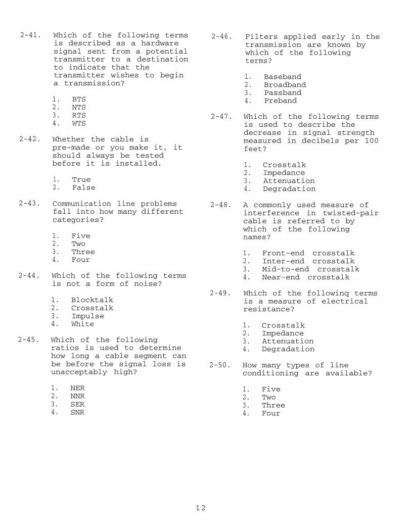
2-41.
2-42.
2-43.
2-44.
2-45.
Which of the following termsis described as a hardwaresignal sent from a potentialtransmitter to a destinationto indicate that thetransmitter wishes to begina transmission?
1. BTS2. NTS3. RTS4. WTS
Whether the cable ispre-made or you make it, itshould always be testedbefore it is installed.
1. True2. False
Communication line problemsfall into how many differentcategories?
1. Five2. Two3. Three4. Four
Which of the following termsis not a form of noise?
1. Blocktalk2. Crosstalk3. Impulse4. White
Which of the followingratios is used to determinehow long a cable segment canbe before the signal loss isunacceptably high?
1. NER2. NNR3. SER4. SNR
2-46.
2-47.
2-48.
2-49.
2-50.
Filters applied early in thetransmission are known bywhich of the followingterms?
1. Baseband2. Broadband3. Passband4. Preband
Which of the following termsis used to describe thedecrease in signal strengthmeasured in decibels per 100feet?
1. Crosstalk2. Impedance3. Attenuation4. Degradation
A commonly used measure ofinterference in twisted-paircable is referred to bywhich of the followingnames?
1.2.3.4.
Front-end crosstalkInter-end crosstalkMid-to-end crosstalkNear-end crosstalk
Which of the followinq termsis a measure of electricalresistance?
1. Crosstalk2. Impedance3. Attenuation4. Degradation
How many types of lineconditioning are available?
1. Five2. Two3. Three4. Four
12

2-51. Which of the followingequipment is used to extendthe transmission rangebetween devices that areconnected directly to eachother?
1. Line conditioner2. Line driver3. Network analyzer4. Time domain
reflectometer
13


![Petroleum, petrochemical and natural gas industries ...dl.mpedia.ir/e-books/21-[ISO]ISO 14224-reliability-and-maintenance-data... · ISO 14224:2016(E) Foreword ISO (the International](https://img.dokumen.tips/doc/110x75/5e04f0b55f377724883ea05f/petroleum-petrochemical-and-natural-gas-industries-dl-isoiso-14224-reliability-and-maintenance-data.jpg)