Embed Size (px)
Citation preview
A Reference numberISO 14224:1999(E)
INTERNATIONALSTANDARD
ISO14224
First edition1999-07-15
Petroleum and natural gas industries —Collection and exchange of reliability andmaintenance data for equipment
Industries du pétrole et du gaz naturel — Recueil et échange de donnéesde fiabilité et de maintenance des équipements
Copyright International Organization for Standardization Reproduced by IHS under license with ISO
Document provided by IHS Licensee=Amerada Hess WAN SSPPU/5958418001, User=MHALL, 04/21/2004 19:31:52 MDT Questions or comments about this message: please callthe Document Policy Group at 303-397-2295.
--````,``,,,`,,```,```,`,``,``,`,``````,,`,`,,,`````-`-`,,`,,`,`,,`---
ISO 14224:1999(E)
© ISO 1999
All rights reserved. Unless otherwise specified, no part of this publication may be reproduced or utilized in any form or by any means, electronicor mechanical, including photocopying and microfilm, without permission in writing from the publisher.
International Organization for StandardizationCase postale 56 • CH-1211 Genève 20 • SwitzerlandInternet [email protected]
Printed in Switzerland
ii
Contents
1 Scope ........................................................................................................................ ................................................1
2 Normative reference .......................................................................................................... ......................................2
3 Terms, definitions and abbreviated terms ..................................................................................... .......................2
3.1 Terms and definitions ...................................................................................................... ....................................2
3.2 Abbreviations .............................................................................................................. ..........................................5
4 Quality of data.............................................................................................................. ............................................6
4.1 Definition of data quality................................................................................................. .....................................6
4.2 Guidance for obtaining quality data ........................................................................................ ...........................6
4.3 Data source systems........................................................................................................ ....................................6
5 Equipment boundary and hierarchy ............................................................................................. .........................7
5.1 Boundary description....................................................................................................... ....................................7
5.2 Guidance for defining an equipment hierarchy............................................................................... ..................7
6 Information structure ........................................................................................................ ......................................9
6.1 Data categories ............................................................................................................ .........................................9
6.2 Data format ................................................................................................................ ............................................9
6.3 Database structure ......................................................................................................... ....................................12
7 Equipment, failure and maintenance data...................................................................................... .....................12
7.1 Equipment data............................................................................................................. ......................................12
7.2 Failure data............................................................................................................... ...........................................13
7.3 Maintenance data........................................................................................................... .....................................13
Annex A (informative) Equipment class attributes ................................................................................................14
A.1 Advisory notes ........................................................................................................... ......................................14
A.2 Process equipment ........................................................................................................ ..................................15
Copyright International Organization for Standardization Reproduced by IHS under license with ISO
Document provided by IHS Licensee=Amerada Hess WAN SSPPU/5958418001, User=MHALL, 04/21/2004 19:31:52 MDT Questions or comments about this message: please callthe Document Policy Group at 303-397-2295.
--````,``,,,`,,```,```,`,``,``,`,``````,,`,`,,,`````-`-`,,`,,`,`,,`---
© ISO ISO 14224:1999(E)
iii
A.3 Subsea equipment ........................................................................................................ .................................. 48
A.4 Well-completion equipment ................................................................................................ ............................ 52
A.5 Drilling equipment....................................................................................................... ..................................... 58
Annex B (informative) Failure and maintenance notations................................................................................... 63
Annex C (informative) Quality control checklist .................................................................................................... 67
C.1 Quality control before and during data collection........................................................................ ................ 67
C.2 Verification of collected data ........................................................................................... ............................... 67
Annex D (informative) Typical requirements for data............................................................................................ 69
Bibliography................................................................................................................... ........................................... 71
Copyright International Organization for Standardization Reproduced by IHS under license with ISO
Document provided by IHS Licensee=Amerada Hess WAN SSPPU/5958418001, User=MHALL, 04/21/2004 19:31:52 MDT Questions or comments about this message: please callthe Document Policy Group at 303-397-2295.
--````,``,,,`,,```,```,`,``,``,`,``````,,`,`,,,`````-`-`,,`,,`,`,,`---
ISO 14224:1999(E)
iv
Foreword
ISO (the International Organization for standardization) is a worldwide federation of national standards bodies (ISOmember bodies). The work of preparing International Standards is normally carried out through ISO technicalcommittees. Each member body interested in a subject for which a technical committee has been established hasthe right to be represented on that committee. International organizations, governmental and non-governmental, inliaison with ISO, also take part in the work. ISO collaborates closely with the International ElectrotechnicalCommission (IEC) on all matters of electrotechnical standardization.
International Standards are drafted in accordance with the rules given in the ISO/IEC Directives, Part 3.
Draft International Standards adopted by the technical committees are circulated to the member bodies for voting.Publication as an International Standard requires approval by at least 75 % of the member bodies casting a vote.
International Standard ISO 14224 was prepared by Technical Committee ISO/TC 67, Materials, equipment andoffshore structures for petroleum and natural gas industries.
Annexes A, B, C and D of this International Standard are for information only.
Copyright International Organization for Standardization Reproduced by IHS under license with ISO
Document provided by IHS Licensee=Amerada Hess WAN SSPPU/5958418001, User=MHALL, 04/21/2004 19:31:52 MDT Questions or comments about this message: please callthe Document Policy Group at 303-397-2295.
--````,``,,,`,,```,```,`,``,``,`,``````,,`,`,,,`````-`-`,,`,,`,`,,`---
© ISO ISO 14224:1999(E)
v
Introduction
This International Standard has been prepared based on know-how and experience gained through the datacollection project OREDA1),
which has been carried out by several major oil companies since the early 1980s.
During these years, a large amount of data have been collected and substantial knowledge in reliability datacollection accumulated. The text of this International Standard relating to downhole equipment is based on know-how and experience gained through the WELLMASTER 2) project.
In the petroleum and natural gas industry, great attention is being paid to safety, reliability and maintainability ofequipment. Various analyses are used to estimate the risk of hazards, pollution or damage to equipment. For suchanalyses, Reliability and Maintenance (RM) data are vital.
More emphasis has recently been put on cost-effective design and maintenance for new plants and existinginstallations. In this respect data on failures, failure mechanisms and maintenance have become of increasedimportance.
Data collection is an investment. By standardization and improved facility information management systems thatallow electronic collection and transfer of data, quality can be improved. A cost-effective way to maximize theamount and type of data is through industry cooperation. To make it possible to collect, exchange and analyse databased on common ground, a standard is required. This International Standard gives recommendations to thepetroleum and natural gas industry on specification and execution of RM data collection, both as a separateexercise and in the day-to-day recording of historical data in maintenance management systems.
1) Guideline for Data Collection.
2) User’s Guide and Reliability Data Collection Guidelines for Well Completion Equipment (1995): ISBN 82-595-8586-3.
Copyright International Organization for Standardization Reproduced by IHS under license with ISO
Document provided by IHS Licensee=Amerada Hess WAN SSPPU/5958418001, User=MHALL, 04/21/2004 19:31:52 MDT Questions or comments about this message: please callthe Document Policy Group at 303-397-2295.
--````,``,,,`,,```,```,`,``,``,`,``````,,`,`,,,`````-`-`,,`,,`,`,,`---
INTERNATIONAL STANDARD © ISO ISO 14224:1999(E)
1
Petroleum and natural gas industries — Collection and exchangeof reliability and maintenance data for equipment
1 Scope
This International Standard provides a comprehensive basis for the collection of Reliability and Maintenance (RM)data in a standard format in the areas of drilling, production, refining and transport by pipeline of petroleum andnatural gas.
This International Standard presents guidelines for the specification, collection and quality assurance of RM data,facilitating the collection of RM data. The data will enable the user to quantify the reliability of the equipment and tocompare the reliability of equipment with similar characteristics.
By analysing the data, reliability parameters can be determined for use in design, operation and maintenance.However, this International Standard is not applicable to the method of analysis for RM data.
The main objectives of this International Standard are:
a) to specify the data to be collected for analysis of:
system design and configuration;
safety, reliability and availability of systems and plants;
life cycle cost;
planning, optimization and execution of maintenance.
b) to specify data in a standardized format in order to:
permit exchange of RM data between plants, owners, manufacturers and contractors;
ensure that RM data are of sufficient quality for the intended analysis.
This International Standard is applicable to all equipment types used in the petroleum and natural gas industry, suchas process equipment (used on onshore and offshore installations), subsea equipment, well-completion equipmentand drilling equipment. In annex A several examples are included.
This International Standard is applicable to data collected in the operational phase.
Due to the variety of different uses for RM data, it is stressed that, for each data collection programme, attentionshould be given to the appropriate level of data required.
NOTE It is recognized that to strengthen the goal of this International Standard, a normative reference detailing all thetaxonomy codes for each of these equipment classes is appropriate. However, since no comprehensive taxonomy listingcovering all equipment classes exists at the time of publication of this International Standard, a sample of taxonomies forprocess equipment, subsea equipment, well-completion equipment and drilling equipment is contained in informative annex A.
Copyright International Organization for Standardization Reproduced by IHS under license with ISO
Document provided by IHS Licensee=Amerada Hess WAN SSPPU/5958418001, User=MHALL, 04/21/2004 19:31:52 MDT Questions or comments about this message: please callthe Document Policy Group at 303-397-2295.
--````,``,,,`,,```,```,`,``,``,`,``````,,`,`,,,`````-`-`,,`,,`,`,,`---
ISO 14224:1999(E) © ISO
2
2 Normative reference
The following normative document contains provisions which, through reference in this text, constitute provisions ofthis International Standard. For dated references, subsequent amendments to, or revisions of, this publication donot apply. However, parties to agreements based on this International Standard are encouraged to investigate thepossibility of applying the most recent edition of the normative document indicated below. For undated references,the latest edition of the normative document referred to applies. Members of ISO and IEC maintain registers ofcurrently valid International Standards.
IEC 60050-191:1990, International Electrotechnical Vocabulary. Chapter 191: Dependability and quality of service.
3 Terms, definitions and abbreviated terms
3.1 Terms and definitions
For the purposes of this International Standard, the following terms and definitions apply.
3.1.1availabilityability of an item to be in a state to perform a required function under given conditions at a given instant of time orover a given time interval, assuming that the required external resources are provided
[IEC 60050-191:1990]
3.1.2active maintenance timethat part of the maintenance time during which a maintenance action is performed on an item, either automaticallyor manually, excluding logistic delays
[IEC 60050-191:1990]
NOTE For more specific information, refer to Figure 191-10 "Maintenance time diagram" in IEC 60050-191.
3.1.3corrective maintenancemaintenance carried out after fault recognition and intended to put an item into a state in which it can perform arequired function
[IEC 60050-191:1990]
NOTE For more specific information, refer to Figure 191-10 "Maintenance time diagram" in IEC 60050-191.
3.1.4critical failurefailure of an equipment unit which causes an immediate cessation of the ability to perform its required function
NOTE For well-completion equipment, see additional information in A.4.5.
3.1.5data acquirerperson or organization in charge of the data collection process
3.1.6demandactivation of the function (includes both operational and test activation)
Copyright International Organization for Standardization Reproduced by IHS under license with ISO
Document provided by IHS Licensee=Amerada Hess WAN SSPPU/5958418001, User=MHALL, 04/21/2004 19:31:52 MDT Questions or comments about this message: please callthe Document Policy Group at 303-397-2295.
--````,``,,,`,,```,```,`,``,``,`,``````,,`,`,,,`````-`-`,,`,,`,`,,`---
© ISO ISO 14224:1999(E)
3
3.1.7down statestate of an item characterized either by a fault or by a possible inability to perform a required function duringpreventive maintenance
[IEC 60050-191:1990]
3.1.8down timetime interval during which an item is in a down state
[IEC 60050-191:1990]
NOTE For more specific information, refer to Figure 191-10 "Maintenance time diagram" in IEC 60050-191.
3.1.9equipment classclass of equipment units
EXAMPLE All pumps.
NOTE For well-completion equipment, see additional information in A.4.5.
3.1.10equipment unitspecific equipment unit within an equipment class as defined within the main boundary
EXAMPLE A pump.
3.1.11equipment unit redundancy·on the equipment unit levelÒ existence of more than one means for performing the required function
EXAMPLE 3 ¥ 50 %.
3.1.12failuretermination of the ability of an item to perform a required function
[IEC 60050-191:1990]
3.1.13failure causecircumstances during design, manufacture or use which have led to a failure
[IEC 60050-191:1990]
NOTE Identification of the failure cause normally requires some in-depth investigation to uncover the underlying human ororganizational factors as well as the technical cause.
3.1.14failure descriptorapparent, observed cause of a failure
NOTE As normally reported into the maintenance management system.
3.1.15failure mechanismphysical, chemical or other process which has led to a failure
[IEC 60050-191:1990]
Copyright International Organization for Standardization Reproduced by IHS under license with ISO
Document provided by IHS Licensee=Amerada Hess WAN SSPPU/5958418001, User=MHALL, 04/21/2004 19:31:52 MDT Questions or comments about this message: please callthe Document Policy Group at 303-397-2295.
--````,``,,,`,,```,```,`,``,``,`,``````,,`,`,,,`````-`-`,,`,,`,`,,`---
ISO 14224:1999(E) © ISO
4
3.1.16failure modeobserved manner of failure
3.1.17faultstate of an item characterized by inability to perform a required function, excluding such inability during preventivemaintenance or other planned actions, or due to lack of external resources
[IEC 60050-191:1990]
3.1.18itemany part, component, device, subsystem, functional unit, equipment or system that can be individually considered
[IEC 60050-191:1990]
3.1.19maintainable itemitem that constitutes a part, or an assembly of parts, that is normally the lowest level in the hierarchy duringmaintenance
3.1.20maintenancecombination of all technical and administrative actions, including supervisory actions, intended to retain an item in,or restore it to, a state in which it can perform a required function
[IEC 60050-191:1990]
3.1.21maintenance man-houraccumulated durations of the individual maintenance times, expressed in hours, used by all maintenance personnelfor a given type of maintenance action or over a given time interval
[IEC 60050-191:1990]
NOTE For more specific information, refer to Figure 191-10 "Maintenance time diagram" in IEC 60050-191.
3.1.22non-critical failurefailure of an equipment unit which does not cause an immediate cessation of the ability to perform its requiredfunction
NOTE For well-completion equipment, see additional information in A.4.5.
3.1.23operating statestate when an item is performing a required function
[IEC 60050-191:1990]
3.1.24operating timetime interval during which an item is in an operating state
[IEC 60050-191:1990]
NOTE For well-completion equipment, see additional information in A.4.5.
Copyright International Organization for Standardization Reproduced by IHS under license with ISO
Document provided by IHS Licensee=Amerada Hess WAN SSPPU/5958418001, User=MHALL, 04/21/2004 19:31:52 MDT Questions or comments about this message: please callthe Document Policy Group at 303-397-2295.
--````,``,,,`,,```,```,`,``,``,`,``````,,`,`,,,`````-`-`,,`,,`,`,,`---
© ISO ISO 14224:1999(E)
5
3.1.25preventive maintenancemaintenance carried out at predetermined intervals or according to prescribed criteria, and intended to reduce theprobability of failure or the degradation of the functioning of an item
[IEC 60050-191:1990]
3.1.26redundancy·in an itemÒ existence of more than one means for performing a required function
[IEC 60050-191:1990]
3.1.27reliabilityperformanceability of an item to perform a required function under given conditions for a given time interval
[IEC 60050-191:1990]
3.1.28required functionfunction, or combination of functions, of an item which is considered necessary to provide a given service
[IEC 60050-191:1990]
3.1.29severity classeffect on equipment unit function
3.1.30subunitassembly of items that provides a specific function that is required for the equipment unit within the main boundaryto achieve its intended performance
3.1.31surveillance periodinterval of time between the start date and end date of data collection
3.2 Abbreviations
BEN Benchmarking
LCC Life Cycle Cost
MI Maintainable Item
OREDA Project for collection of oil and gas industry equipment reliability and maintenance data
PM Preventive Maintenance
QRA Quantitative Risk Assessment
RAM Reliability, Availability and Maintainability analysis
RCM Reliability-Centred Maintenance
RM Reliability and Maintenance
WELLMASTER Reliability data collection for well-completion equipment
Copyright International Organization for Standardization Reproduced by IHS under license with ISO
Document provided by IHS Licensee=Amerada Hess WAN SSPPU/5958418001, User=MHALL, 04/21/2004 19:31:52 MDT Questions or comments about this message: please callthe Document Policy Group at 303-397-2295.
--````,``,,,`,,```,```,`,``,``,`,``````,,`,`,,,`````-`-`,,`,,`,`,,`---
ISO 14224:1999(E) © ISO
6
4 Quality of data
4.1 Definition of data quality
Confidence in the collected RM data, and hence any analysis, is strongly dependent on the quality of the datacollected. High-quality data is characterized by:
completeness of data in relation to specification;
compliance with definitions of reliability parameters, data types and formats;
accurate input, transfer, handling and storage of data (manually or electronic).
4.2 Guidance for obtaining quality data
To obtain high quality data, the following measures shall be emphasized before the data collection process starts:
investigate the data sources to make sure the required inventory data can be found and the operational dataare complete;
define the objective for collecting the data in order to collect relevant data for the intended use. Examples ofanalyses where such data may be used are: Quantitative Risk Analysis (QRA); Reliability, Availability andMaintainability Analysis (RAM); Reliability-Centred Maintenance (RCM); Life Cycle Cost (LCC);
investigate the source(s) of the data to ensure that relevant data of sufficient quality is available;
identify the installation date, population and operating period(s) for the equipment from which data may becollected;
a pilot exercise of the data collection methods and tools (manual, electronic) is recommended to verify thefeasibility of the planned data collection procedures;
prepare a plan for the data collection process, e.g. schedules, milestones, sequence and number of equipmentunits, time periods to be covered, etc.;
train, motivate and organize the data collection personnel;
plan for quality assurance of the data collection process. This shall as a minimum include procedures for qualitycontrol of data and recording and correcting deviations. An example of a checklist is included in Annex C.
During and after the data collection exercise, analyse the data to check consistency, reasonable distributions,proper codes and correct interpretations. The quality control process shall be documented. When merging individualdata bases it is imperative that each data record has a unique identification.
4.3 Data source systems
The facility maintenance management system constitutes the main source of RM data. The quality of the data whichcan be retrieved from this source is dependent on the way RM data is reported in the first place. Reporting of RMdata according to this International Standard shall be allowed for in the facility maintenance management system,thereby providing a more consistent and sound basis for transferring RM data to equipment RM databases.
The level of detail of RM data reported and collected shall be closely linked to the production and safety importanceof the equipment. Prioritization shall be based on regularity, safety and other criticality evaluations.
Those responsible for reporting RM data will derive benefit from the use of these data. Involvement of these staff indetermining and communicating these benefits is a requirement for quality RM data.
Copyright International Organization for Standardization Reproduced by IHS under license with ISO
Document provided by IHS Licensee=Amerada Hess WAN SSPPU/5958418001, User=MHALL, 04/21/2004 19:31:52 MDT Questions or comments about this message: please callthe Document Policy Group at 303-397-2295.
--````,``,,,`,,```,```,`,``,``,`,``````,,`,`,,,`````-`-`,,`,,`,`,,`---
© ISO ISO 14224:1999(E)
7
5 Equipment boundary and hierarchy
5.1 Boundary description
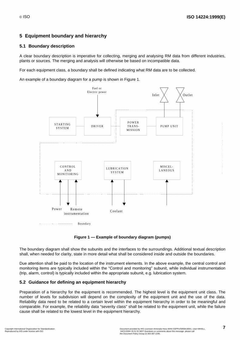
A clear boundary description is imperative for collecting, merging and analysing RM data from different industries,plants or sources. The merging and analysis will otherwise be based on incompatible data.
For each equipment class, a boundary shall be defined indicating what RM data are to be collected.
An example of a boundary diagram for a pump is shown in Figure 1.
S T A R T I N GS Y S T E M
D R I V E RP O W E RT R A N S -
M I S S I O NP U M P U N I T
Fuel orElectr ic power
C O N T R O LA N D
M O N I T O R I N G
L U B R I C A T I O NS Y S T E M
MISCEL-L A N E O U S
Boundary
Power Remoteinst rumentat ion
Coo lant
Inlet Out le t
Figure 1 — Example of boundary diagram (pumps)
The boundary diagram shall show the subunits and the interfaces to the surroundings. Additional textual descriptionshall, when needed for clarity, state in more detail what shall be considered inside and outside the boundaries.
Due attention shall be paid to the location of the instrument elements. In the above example, the central control andmonitoring items are typically included within the “Control and monitoring” subunit, while individual instrumentation(trip, alarm, control) is typically included within the appropriate subunit, e.g. lubrication system.
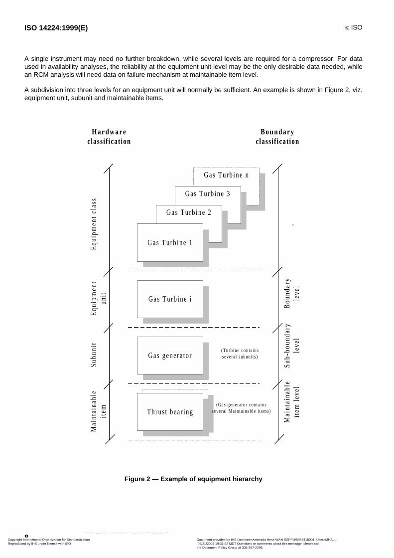
5.2 Guidance for defining an equipment hierarchy
Preparation of a hierarchy for the equipment is recommended. The highest level is the equipment unit class. Thenumber of levels for subdivision will depend on the complexity of the equipment unit and the use of the data.Reliability data need to be related to a certain level within the equipment hierarchy in order to be meaningful andcomparable. For example, the reliability data “severity class” shall be related to the equipment unit, while the failurecause shall be related to the lowest level in the equipment hierarchy.
Copyright International Organization for Standardization Reproduced by IHS under license with ISO
Document provided by IHS Licensee=Amerada Hess WAN SSPPU/5958418001, User=MHALL, 04/21/2004 19:31:52 MDT Questions or comments about this message: please callthe Document Policy Group at 303-397-2295.
--````,``,,,`,,```,```,`,``,``,`,``````,,`,`,,,`````-`-`,,`,,`,`,,`---
ISO 14224:1999(E) © ISO
8
A single instrument may need no further breakdown, while several levels are required for a compressor. For dataused in availability analyses, the reliability at the equipment unit level may be the only desirable data needed, whilean RCM analysis will need data on failure mechanism at maintainable item level.
A subdivision into three levels for an equipment unit will normally be sufficient. An example is shown in Figure 2, viz.equipment unit, subunit and maintainable items.
Gas Turb ine n
Gas Turb ine 3
Gas Turb ine i
Gas Turb ine 2
Gas Turb ine 1
Gas genera tor
Thrust bear ing
Hardwareclassif icat ion
Boundaryclassif icat ion
Equ
ipm
ent
clas
sE
quip
men
tun
itS
ubun
itM
aint
aina
ble
item
Bou
ndar
yle
vel
Sub
-bou
ndar
yle
vel
Mai
ntai
nabl
eit
em l
evel
-
(Turb ine conta insseveral subuni ts)
(Gas generator conta inssevera l Mainta inable i tems)
Figure 2 — Example of equipment hierarchy
Copyright International Organization for Standardization Reproduced by IHS under license with ISO
Document provided by IHS Licensee=Amerada Hess WAN SSPPU/5958418001, User=MHALL, 04/21/2004 19:31:52 MDT Questions or comments about this message: please callthe Document Policy Group at 303-397-2295.
--````,``,,,`,,```,```,`,``,``,`,``````,,`,`,,,`````-`-`,,`,,`,`,,`---
© ISO ISO 14224:1999(E)
9
6 Information structure
6.1 Data categories
The RM data shall be collected in an organized and structured way. The major data categories for equipment,failure and maintenance data are given below.
a) Equipment data
The description of equipment is characterized by:
1) identification data, e.g. equipment location, classification, installation data, equipment unit data;
2) design data, e.g. manufacturer’s data, design characteristics;
3) application data, e.g. operation, environment.
These data categories shall be general for all equipment classes, e.g. type classification, and specific for eachequipment unit, e.g. number of stages for a compressor. This shall be reflected in the database structure. Formore details see Table 1.
b) Failure data
These data are characterized by:
1) identification data, failure record and equipment location;
2) failure data for characterizing a failure, e.g. failure date, maintainable items failed, severity class, failuremode, failure cause, method of observation.
For more details see Table 2.
c) Maintenance data
These data are characterized by:
1) identification data; e.g. maintenance record, equipment location, failure record;
2) maintenance data; parameters characterizing a maintenance, e.g. date of maintenance, maintenancecategory, maintenance activity, items maintained, maintenance man hours per discipline, active mainte-nance time, down time.
For more details see Table 3.
The type of failure and maintenance data shall normally be common for all equipment classes, with exceptionswhere specific data types need to be collected, e.g. subsea equipment.
Corrective maintenance events shall be recorded in order to describe the corrective action following a failure.Preventive maintenance records are required to retain the complete lifetime history of an equipment unit.
6.2 Data format
Each record, e.g. a failure event, shall be identified in the database by a number of attributes. Each attributedescribes one piece of information, e.g. the failure mode. It is recommended that each piece of information becoded where possible. The advantages of this approach versus free text are:
facilitation of queries and analysis of data;
ease of data input;
consistency check undertaken at input, by having pre-defined codes.
Copyright International Organization for Standardization Reproduced by IHS under license with ISO
Document provided by IHS Licensee=Amerada Hess WAN SSPPU/5958418001, User=MHALL, 04/21/2004 19:31:52 MDT Questions or comments about this message: please callthe Document Policy Group at 303-397-2295.
--````,``,,,`,,```,```,`,``,``,`,``````,,`,`,,,`````-`-`,,`,,`,`,,`---
ISO 14224:1999(E) © ISO
10
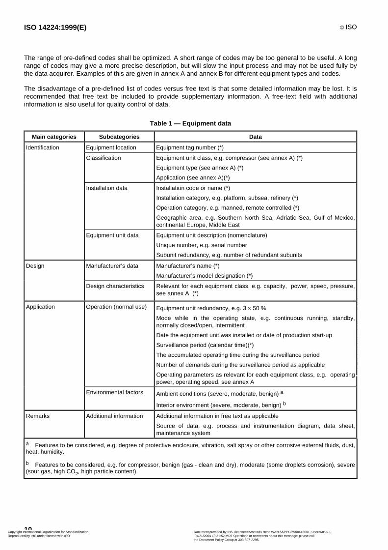
The range of pre-defined codes shall be optimized. A short range of codes may be too general to be useful. A longrange of codes may give a more precise description, but will slow the input process and may not be used fully bythe data acquirer. Examples of this are given in annex A and annex B for different equipment types and codes.
The disadvantage of a pre-defined list of codes versus free text is that some detailed information may be lost. It isrecommended that free text be included to provide supplementary information. A free-text field with additionalinformation is also useful for quality control of data.
Table 1 — Equipment data
Main categories Subcategories Data
Identification Equipment location Equipment tag number (*)
Classification Equipment unit class, e.g. compressor (see annex A) (*)
Equipment type (see annex A) (*)
Application (see annex A)(*)
Installation data Installation code or name (*)
Installation category, e.g. platform, subsea, refinery (*)
Operation category, e.g. manned, remote controlled (*)
Geographic area, e.g. Southern North Sea, Adriatic Sea, Gulf of Mexico,continental Europe, Middle East
Equipment unit data Equipment unit description (nomenclature)
Unique number, e.g. serial number
Subunit redundancy, e.g. number of redundant subunits
Design Manufacturer’s data Manufacturer’s name (*)
Manufacturer’s model designation (*)
Design characteristics Relevant for each equipment class, e.g. capacity, power, speed, pressure,see annex A (*)
Application Operation (normal use) Equipment unit redundancy, e.g. 3 ¥ 50 %
Mode while in the operating state, e.g. continuous running, standby,normally closed/open, intermittent
Date the equipment unit was installed or date of production start-up
Surveillance period (calendar time)(*)
The accumulated operating time during the surveillance period
Number of demands during the surveillance period as applicable
Operating parameters as relevant for each equipment class, e.g. operatingpower, operating speed, see annex A
Environmental factors Ambient conditions (severe, moderate, benign) a
Interior environment (severe, moderate, benign) b
Remarks Additional information Additional information in free text as applicable
Source of data, e.g. process and instrumentation diagram, data sheet,maintenance system
a Features to be considered, e.g. degree of protective enclosure, vibration, salt spray or other corrosive external fluids, dust,heat, humidity.
b Features to be considered, e.g. for compressor, benign (gas - clean and dry), moderate (some droplets corrosion), severe(sour gas, high CO2, high particle content).
Copyright International Organization for Standardization Reproduced by IHS under license with ISO
Document provided by IHS Licensee=Amerada Hess WAN SSPPU/5958418001, User=MHALL, 04/21/2004 19:31:52 MDT Questions or comments about this message: please callthe Document Policy Group at 303-397-2295.
--````,``,,,`,,```,```,`,``,``,`,``````,,`,`,,,`````-`-`,,`,,`,`,,`---
© ISO ISO 14224:1999(E)
11
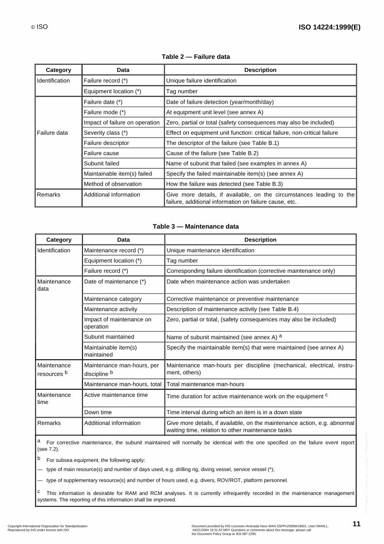
Table 2 — Failure data
Category Data Description
Identification Failure record (*) Unique failure identification
Equipment location (*) Tag number
Failure date (*) Date of failure detection (year/month/day)
Failure mode (*) At equipment unit level (see annex A)
Impact of failure on operation Zero, partial or total (safety consequences may also be included)
Failure data Severity class (*) Effect on equipment unit function: critical failure, non-critical failure
Failure descriptor The descriptor of the failure (see Table B.1)
Failure cause Cause of the failure (see Table B.2)
Subunit failed Name of subunit that failed (see examples in annex A)
Maintainable item(s) failed Specify the failed maintainable item(s) (see annex A)
Method of observation How the failure was detected (see Table B.3)
Remarks Additional information Give more details, if available, on the circumstances leading to thefailure, additional information on failure cause, etc.
Table 3 — Maintenance data
Category Data Description
Identification Maintenance record (*) Unique maintenance identification
Equipment location (*) Tag number
Failure record (*) Corresponding failure identification (corrective maintenance only)
Maintenancedata
Date of maintenance (*) Date when maintenance action was undertaken
Maintenance category Corrective maintenance or preventive maintenance
Maintenance activity Description of maintenance activity (see Table B.4)
Impact of maintenance onoperation
Zero, partial or total, (safety consequences may also be included)
Subunit maintained Name of subunit maintained (see annex A) a
Maintainable item(s)maintained
Specify the maintainable item(s) that were maintained (see annex A)
Maintenance
resources bMaintenance man-hours, per
discipline bMaintenance man-hours per discipline (mechanical, electrical, instru-ment, others)
Maintenance man-hours, total Total maintenance man-hours
Maintenancetime
Active maintenance time Time duration for active maintenance work on the equipment c
Down time Time interval during which an item is in a down state
Remarks Additional information Give more details, if available, on the maintenance action, e.g. abnormalwaiting time, relation to other maintenance tasks
a For corrective maintenance, the subunit maintained will normally be identical with the one specified on the failure event report(see 7.2).
b For subsea equipment, the following apply:
— type of main resource(s) and number of days used, e.g. drilling rig, diving vessel, service vessel (*);
— type of supplementary resource(s) and number of hours used, e.g. divers, ROV/ROT, platform personnel.
c This information is desirable for RAM and RCM analyses. It is currently infrequently recorded in the maintenance managementsystems. The reporting of this information shall be improved.
Copyright International Organization for Standardization Reproduced by IHS under license with ISO
Document provided by IHS Licensee=Amerada Hess WAN SSPPU/5958418001, User=MHALL, 04/21/2004 19:31:52 MDT Questions or comments about this message: please callthe Document Policy Group at 303-397-2295.
--````,``,,,`,,```,```,`,``,``,`,``````,,`,`,,,`````-`-`,,`,,`,`,,`---
ISO 14224:1999(E) © ISO
12
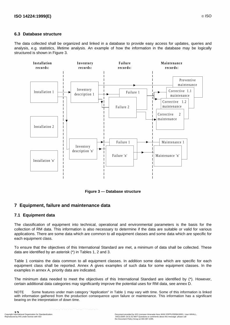
6.3 Database structure
The data collected shall be organized and linked in a database to provide easy access for updates, queries andanalysis, e.g. statistics, lifetime analysis. An example of how the information in the database may be logicallystructured is shown in Figure 3.
Main tenance 1
Inventorydescr ip t ion 1 Fai lure 1
Fai lure 2
Prevent ivemain tenance
Correct ive 1 .1ma in tenance
Correct ive 1 .2ma in tenance
Correct ive 2ma in tenance
Inven to ryrecords :
Fa i lu rerecords :
Ma in tenancerecords :
Inventorydescr ipt ion 'n '
Fa i lure 1
Fai lure 'n ' Main tenance 'n '
Insta l lat ion 1
Insta l lat ion 2
Instal lat ion 'n '
Insta l la t ionrecords :
Figure 3 — Database structure
7 Equipment, failure and maintenance data
7.1 Equipment data
The classification of equipment into technical, operational and environmental parameters is the basis for thecollection of RM data. This information is also necessary to determine if the data are suitable or valid for variousapplications. There are some data which are common to all equipment classes and some data which are specific foreach equipment class.
To ensure that the objectives of this International Standard are met, a minimum of data shall be collected. Thesedata are identified by an asterisk (*) in Tables 1, 2 and 3.
Table 1 contains the data common to all equipment classes. In addition some data which are specific for eachequipment class shall be reported. Annex A gives examples of such data for some equipment classes. In theexamples in annex A, priority data are indicated.
The minimum data needed to meet the objectives of this International Standard are identified by (*). However,certain additional data categories may significantly improve the potential uses for RM data, see annex D.
NOTE Some features under main category “Application” in Table 1 may vary with time. Some of this information is linkedwith information gathered from the production consequence upon failure or maintenance. This information has a significantbearing on the interpretation of down time.
Copyright International Organization for Standardization Reproduced by IHS under license with ISO
Document provided by IHS Licensee=Amerada Hess WAN SSPPU/5958418001, User=MHALL, 04/21/2004 19:31:52 MDT Questions or comments about this message: please callthe Document Policy Group at 303-397-2295.
--````,``,,,`,,```,```,`,``,``,`,``````,,`,`,,,`````-`-`,,`,,`,`,,`---
© ISO ISO 14224:1999(E)
13
7.2 Failure data
A uniform definition of failure and a method of classifying failures are essential when data from different sources(plants and operators) need to be combined in a common RM database.
A common report for all equipment classes shall be used for reporting failure data. The data are given in Table 2.
The minimum data needed to meet the objectives of this International Standard are identified by (*). However,certain additional data categories may significantly improve the potential uses for RM data, see annex D.
7.3 Maintenance data
Maintenance is carried out:
a) to correct a failure (corrective maintenance). The failure shall be reported as described in 7.2;
b) as a planned and normally periodic action to prevent failure from occurring (preventive maintenance).
A common report for all equipment classes shall be used for reporting maintenance data. The data required aregiven in Table 3.
The minimum data needed to meet the objectives of this International Standard are identified by (*). However,certain additional data categories may significantly improve the potential uses for RM data, see annex D.
Copyright International Organization for Standardization Reproduced by IHS under license with ISO
Document provided by IHS Licensee=Amerada Hess WAN SSPPU/5958418001, User=MHALL, 04/21/2004 19:31:52 MDT Questions or comments about this message: please callthe Document Policy Group at 303-397-2295.
--````,``,,,`,,```,```,`,``,``,`,``````,,`,`,,,`````-`-`,,`,,`,`,,`---
ISO 14224:1999(E) © ISO
14
Annex A(informative)
Equipment class attributes
A.1 Advisory notes
A.1.1 General
Annex A gives examples in Tables A.1 to A.66 on how some typical oil and gas equipment may be categorized asto taxonomy, boundary definition, inventory data and failure modes. These data are specific for each equipmentunit. Data common for all equipment units are shown in annex B.
In this categorization, a standardization approach has been applied to classification and subdivision of units. Thismeans that the total number of different data categories and definitions are reduced, while at the same time thereare fewer tailor-made definitions and codes for each individual equipment unit. The user should therefore applythose categories and codes which are applicable to the specific equipment unit for which data are being collected.For equipment units of special design, a more tailor-made categorization than that shown in these examples may berequired.
In the tables in which equipment is broken down into “subunit” and “maintainable items” (e.g. Table A.2), it isrecommended to include additional “maintainable items”, as needed, to cover instrumentation, and an “unknown”category in case information is not available.
A.1.2 Boundary definitions
The purpose of the boundary definition is to ensure a common understanding of what equipment is to be includedwithin the boundary of a particular system, and hence which failures and maintenance to record. For definition of theboundaries, the following rules are recommended:
a) exclude connected items from the equipment unit boundary, unless specifically included by the boundaryspecification. Failures that occur in a connection (e.g. leak), and which cannot be solely related to theconnected item, should be included within the bounday definition;
b) when a driver and the driven unit use a common subunit (e.g. lubrication system), relate failure on this subunit,as a general rule, to the driven unit ;
c) include instrumentation only where it has a specific control and/or monitoring function for the equipment unit inquestion and/or is locally mounted on the equipment unit. Control and supervisory instrumentation of moregeneral use (e.g. SCADA-systems) should not, as a rule, be included.
A.1.3 Failure modes
In annex A, a list of relevant failure modes is given for each equipment unit. The failure modes should be related tothe equipment unit level in the hierarchy. The failure modes used can be categorized in three types:
a) the desired function is not obtained (e.g. fail to start);
b) there is a deviation in a specified function outside accepted limits (e.g. high output);
c) there is a failure indication observed, but there is no immediate and critical impact on equipment unit function(e.g. leakage).
For the latter category the failure mode should describe the failure indication on equipment unit level, while thefailure descriptor should describe the cause of failure on the lowest level within the equipment hierarchy for whichthis information is known.
Copyright International Organization for Standardization Reproduced by IHS under license with ISO
Document provided by IHS Licensee=Amerada Hess WAN SSPPU/5958418001, User=MHALL, 04/21/2004 19:31:52 MDT Questions or comments about this message: please callthe Document Policy Group at 303-397-2295.
--````,``,,,`,,```,```,`,``,``,`,``````,,`,`,,,`````-`-`,,`,,`,`,,`---
© ISO ISO 14224:1999(E)
15
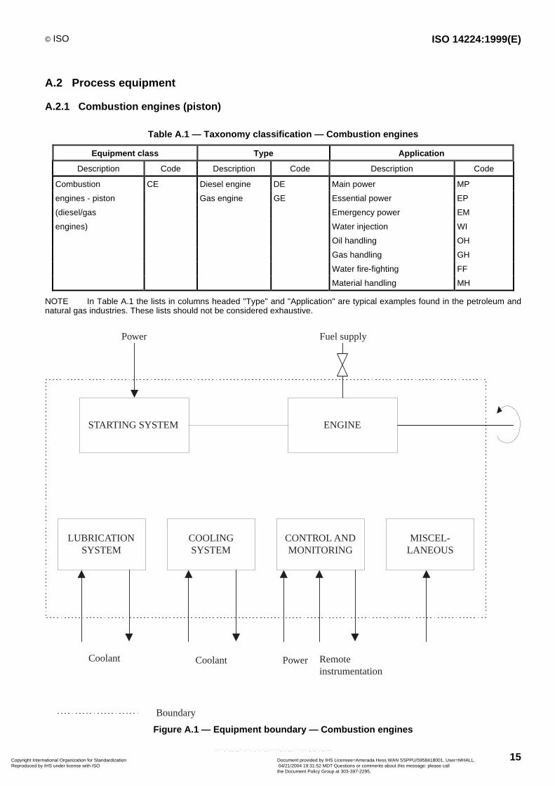
A.2 Process equipment
A.2.1 Combustion engines (piston)
Table A.1 — Taxonomy classification — Combustion engines
Equipment class Type Application
Description Code Description Code Description Code
Combustion CE Diesel engine DE Main power MP
engines - piston Gas engine GE Essential power EP
(diesel/gas Emergency power EM
engines) Water injection WI
Oil handling OH
Gas handling GH
Water fire-fighting FF
Material handling MH
NOTE In Table A.1 the lists in columns headed "Type" and "Application" are typical examples found in the petroleum andnatural gas industries. These lists should not be considered exhaustive.
STARTING SYSTEM ENGINE
Power Fuel supply
LUBRICATIONSYSTEM
COOLINGSYSTEM
CONTROL ANDMONITORING
MISCEL-LANEOUS
Coolant Coolant Power Remoteinstrumentation
Boundary
Figure A.1 — Equipment boundary — Combustion engines
Copyright International Organization for Standardization Reproduced by IHS under license with ISO
Document provided by IHS Licensee=Amerada Hess WAN SSPPU/5958418001, User=MHALL, 04/21/2004 19:31:52 MDT Questions or comments about this message: please callthe Document Policy Group at 303-397-2295.
--````,``,,,`,,```,```,`,``,``,`,``````,,`,`,,,`````-`-`,,`,,`,`,,`---
ISO 14224:1999(E) © ISO
16
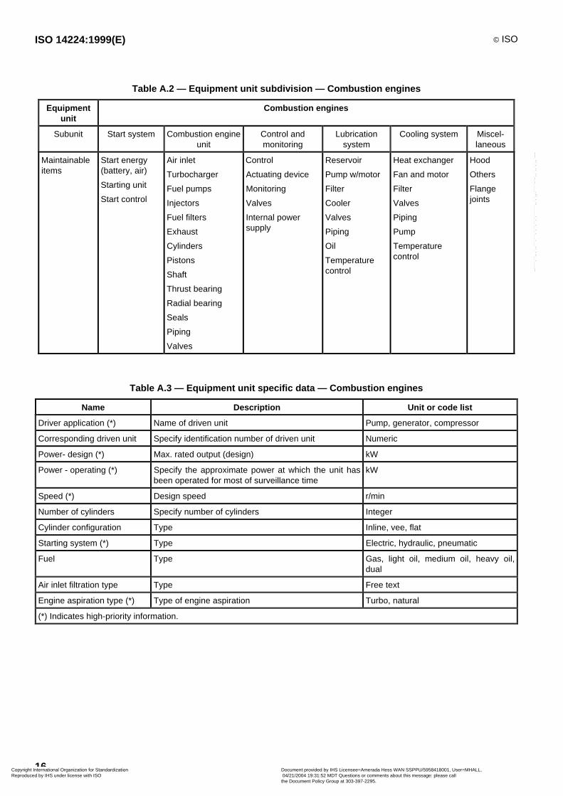
Table A.2 — Equipment unit subdivision — Combustion engines
Equipmentunit
Combustion engines
Subunit Start system Combustion engineunit
Control andmonitoring
Lubricationsystem
Cooling system Miscel-laneous
Maintainableitems
Start energy(battery, air)
Starting unit
Start control
Air inlet
Turbocharger
Fuel pumps
Injectors
Fuel filters
Exhaust
Cylinders
Pistons
Shaft
Thrust bearing
Radial bearing
Seals
Piping
Valves
Control
Actuating device
Monitoring
Valves
Internal powersupply
Reservoir
Pump w/motor
Filter
Cooler
Valves
Piping
Oil
Temperaturecontrol
Heat exchanger
Fan and motor
Filter
Valves
Piping
Pump
Temperaturecontrol
Hood
Others
Flangejoints
Table A.3 — Equipment unit specific data — Combustion engines
Name Description Unit or code list
Driver application (*) Name of driven unit Pump, generator, compressor
Corresponding driven unit Specify identification number of driven unit Numeric
Power- design (*) Max. rated output (design) kW
Power - operating (*) Specify the approximate power at which the unit hasbeen operated for most of surveillance time
kW
Speed (*) Design speed r/min
Number of cylinders Specify number of cylinders Integer
Cylinder configuration Type Inline, vee, flat
Starting system (*) Type Electric, hydraulic, pneumatic
Fuel Type Gas, light oil, medium oil, heavy oil,dual
Air inlet filtration type Type Free text
Engine aspiration type (*) Type of engine aspiration Turbo, natural
(*) Indicates high-priority information.
Copyright International Organization for Standardization Reproduced by IHS under license with ISO
Document provided by IHS Licensee=Amerada Hess WAN SSPPU/5958418001, User=MHALL, 04/21/2004 19:31:52 MDT Questions or comments about this message: please callthe Document Policy Group at 303-397-2295.
--````,``,,,`,,```,```,`,``,``,`,``````,,`,`,,,`````-`-`,,`,,`,`,,`---
© ISO ISO 14224:1999(E)
17
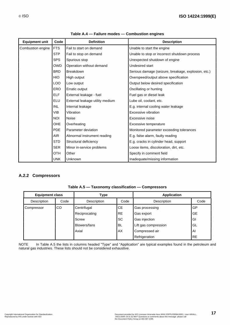
Table A.4 — Failure modes — Combustion engines
Equipment unit Code Definition Description
Combustion engine FTS Fail to start on demand Unable to start the engine
STP Fail to stop on demand Unable to stop or incorrect shutdown process
SPS Spurious stop Unexpected shutdown of engine
OWD Operation without demand Undesired start
BRD Breakdown Serious damage (seizure, breakage, explosion, etc.)
HIO High output Overspeed/output above specification
LOO Low output Output below desired specification
ERO Erratic output Oscillating or hunting
ELF External leakage - fuel Fuel gas or diesel leak
ELU External leakage utility medium Lube oil, coolant, etc.
INL Internal leakage E.g. internal cooling water leakage
VIB Vibration Excessive vibration
NOI Noise Excessive noise
OHE Overheating Excessive temperature
PDE Parameter deviation Monitored parameter exceeding tolerances
AIR Abnormal instrument reading E.g. false alarm, faulty reading
STD Structural deficiency E.g. cracks in cylinder head, support
SER Minor in-service problems Loose items, discoloration, dirt, etc.
OTH Other Specify in comment field
UNK Unknown Inadequate/missing information
A.2.2 Compressors
Table A.5 — Taxonomy classification — Compressors
Equipment class Type Application
Description Code Description Code Description Code
Compressor CO Centrifugal CE Gas processing GP
Reciprocating RE Gas export GE
Screw SC Gas injection GI
Blowers/fans BL Lift gas compression GL
Axial AX Compressed air AI
Refrigeration RE
NOTE In Table A.5 the lists in columns headed "Type" and "Application" are typical examples found in the petroleum andnatural gas industries. These lists should not be considered exhaustive.
Copyright International Organization for Standardization Reproduced by IHS under license with ISO
Document provided by IHS Licensee=Amerada Hess WAN SSPPU/5958418001, User=MHALL, 04/21/2004 19:31:52 MDT Questions or comments about this message: please callthe Document Policy Group at 303-397-2295.
--````,``,,,`,,```,```,`,``,``,`,``````,,`,`,,,`````-`-`,,`,,`,`,,`---
ISO 14224:1999(E) © ISO
18
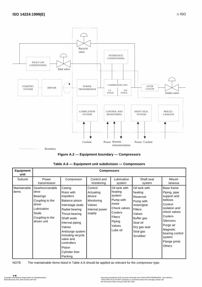
INLET GASCONDITIONING
STARTINGSYSTEM
DRIVERPOWER
TRANSMISSION
COMPRESSOR UNIT
1 st 2ndSTAGE STAGE
INTERSTAGECONDITIONING
Recyclevalve
AFTERCOOLER
LUBRICATIONSYSTEM
CONTROL ANDMONITORING
SHAFT SEALSYSTEM
MISCEL-LANEOUS
Inlet valve
Outlet valve
Coolant PowerRemoteinstrumentation.
Power Coolant
Boundary
Figure A.2 — Equipment boundary — Compressors
Table A.6 — Equipment unit subdivision — Compressors
Equipmentunit
Compressors
Subunit Powertransmission
Compressor Control andmonitoring
Lubricationsystem
Shaft sealsystem
Miscel-laneous
Maintainableitems
Gearbox/variabledriveBearingsCoupling to thedriverLubricationSealsCoupling to thedriven unit
CasingRotor withimpellersBalance pistonInterstage sealsRadial bearingThrust bearingShaft sealsInternal pipingValvesAntisurge systemincluding recyclevalve andcontrollers
PistonCylinder linerPacking
ControlActuatingdeviceMonitoringValvesInternal powersupply
Oil tank withheatingsystemPump withmotorCheck valvesCoolersFiltersPipingValvesLube oil
Oil tank withheatingReservoirPump withmotor/gearFiltersValvesBuffer gasSeal oilDry gas sealSeal gasScrubber
Base framePiping, pipesupport andbellowsControl-isolation andcheck valvesCoolersSilencersPurge airMagneticbearing controlsystemFlange jointsOthers
NOTE The maintainable Items listed in Table A.6 should be applied as relevant for the compressor type.
Copyright International Organization for Standardization Reproduced by IHS under license with ISO
Document provided by IHS Licensee=Amerada Hess WAN SSPPU/5958418001, User=MHALL, 04/21/2004 19:31:52 MDT Questions or comments about this message: please callthe Document Policy Group at 303-397-2295.
--````,``,,,`,,```,```,`,``,``,`,``````,,`,`,,,`````-`-`,,`,,`,`,,`---

© ISO ISO 14224:1999(E)
19
Table A.7 — Equipment unit specific data — Compressors
Name Description Unit or code list
Corresponding driver (*) Specify unique record identificationnumber when relevant
Numeric
Gas handled (*) Average molar mass
(specific gravity ¥ 28,96)
g/mol
Suction pressure - design (*) First stage pascal (bar)
Suction pressure - operating First stage pascal (bar)
Discharge pressure - design (*) Last stage pascal (bar)
Discharge pressure - operating (*) Last stage pascal (bar)
Flowrate - design (*) m3/h
Flowrate - operating m3/h
Discharge temperature - design (*) °C
Discharge temperature - operating °C
Power - design (*) Design power kW
Utilization (*) % utilization compared to design %
Polytrophic head kJ/kg
Number of casings (*) Number of casings in the train Integer
Number of stages (*) Number of compressor stages(not impellers) in this train
Integer
Body type Type Vertical split case (barrel type),axial split case
Shaft sealing Type Mechanical, oil, dry gas-packed,dry gland, labyrinth, combined
Inter cooler fitted Specify if cooler is fitted Yes/no
Shaft seal system (*) Separate, combined, dry, etc. Separate, combined, dry
Radial bearing (*)
Thrust bearing (*)
Type (specify in comment field whetherany thrust pressure regulator isinstalled)
Antifrictional, journal, magnetic
Speed Design speed r/min
Type of driver (*) Type Electric motor, gas turbine, steamturbine, diesel engine, gas en-gine, turboexpander, integral gasmotor
Coupling Type Fixed, flexible, hydraulic,disconnect
Reciprocating compressors only:
Cylinder configuration Inline, opposed, V, W
Cylinder orientation Horizontal, vertical, inclined
Working principle (*) Single-acting, double-acting
Packing type (*) Lubricated, dry
(*) Indicates high priority information.
Copyright International Organization for Standardization Reproduced by IHS under license with ISO
Document provided by IHS Licensee=Amerada Hess WAN SSPPU/5958418001, User=MHALL, 04/21/2004 19:31:52 MDT Questions or comments about this message: please callthe Document Policy Group at 303-397-2295.
--````,``,,,`,,```,```,`,``,``,`,``````,,`,`,,,`````-`-`,,`,,`,`,,`---
ISO 14224:1999(E) © ISO
20
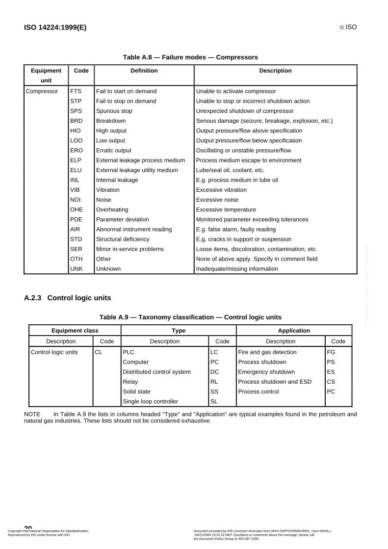
Table A.8 — Failure modes — Compressors
Equipment
unit
Code Definition Description
Compressor FTS Fail to start on demand Unable to activate compressor
STP Fail to stop on demand Unable to stop or incorrect shutdown action
SPS Spurious stop Unexpected shutdown of compressor
BRD Breakdown Serious damage (seizure, breakage, explosion, etc.)
HIO High output Output pressure/flow above specification
LOO Low output Output pressure/flow below specification
ERO Erratic output Oscillating or unstable pressure/flow
ELP External leakage process medium Process medium escape to environment
ELU External leakage utility medium Lube/seal oil, coolant, etc.
INL Internal leakage E.g. process medium in lube oil
VIB Vibration Excessive vibration
NOI Noise Excessive noise
OHE Overheating Excessive temperature
PDE Parameter deviation Monitored parameter exceeding tolerances
AIR Abnormal instrument reading E.g. false alarm, faulty reading
STD Structural deficiency E.g. cracks in support or suspension
SER Minor in-service problems Loose items, discoloration, contamination, etc.
OTH Other None of above apply. Specify in comment field
UNK Unknown Inadequate/missing information
A.2.3 Control logic units
Table A.9 — Taxonomy classification — Control logic units
Equipment class Type Application
Description Code Description Code Description Code
Control logic units CL PLC LC Fire and gas detection FG
Computer PC Process shutdown PS
Distributed control system DC Emergency shutdown ES
Relay RL Process shutdown and ESD CS
Solid state SS Process control PC
Single loop controller SL
NOTE In Table A.9 the lists in columns headed "Type" and "Application" are typical examples found in the petroleum andnatural gas industries. These lists should not be considered exhaustive.
Copyright International Organization for Standardization Reproduced by IHS under license with ISO
Document provided by IHS Licensee=Amerada Hess WAN SSPPU/5958418001, User=MHALL, 04/21/2004 19:31:52 MDT Questions or comments about this message: please callthe Document Policy Group at 303-397-2295.
--````,``,,,`,,```,```,`,``,``,`,``````,,`,`,,,`````-`-`,,`,,`,`,,`---

© ISO ISO 14224:1999(E)
21
INPUT CARDS
ANALOG DIGITALCPU
OUTPUT CARDS
ANALOG DIGITALCONTROLLERS
Operator Station
Otherperipherals
Signalsout
Signalsin
SYSTEM BUS
POWER SUPPLYUNIT
Mains/Power distribution
Boundary
MISCEL-LANEOUS
Figure A.3 — Equipment boundary — Control logic units
Table A.10 — Equipment unit subdivision — Control logic units
Equipmentunit
Control logic units
Subunit Analog inputcards
Digital input cards Analog outputcards
Digital outputcards
Central processor unit
Maintainable Input card Input card Output card Output card Central processor unit (CPU)
items Connection unit Connection unit Connection unit Connection unit Random access memory (RAM)
Relay Relay Watchdog/diagnostics
Software
Subunit Controllers System bus Power supply Miscellaneous
Maintainableitems
Internal bus controller
Visual display unit control (VDU)
Communication control
Disk control
Printer control
(No subdivision) (No subdivision) Others
Copyright International Organization for Standardization Reproduced by IHS under license with ISO
Document provided by IHS Licensee=Amerada Hess WAN SSPPU/5958418001, User=MHALL, 04/21/2004 19:31:52 MDT Questions or comments about this message: please callthe Document Policy Group at 303-397-2295.
--````,``,,,`,,```,```,`,``,``,`,``````,,`,`,,,`````-`-`,,`,,`,`,,`---
ISO 14224:1999(E) © ISO
22
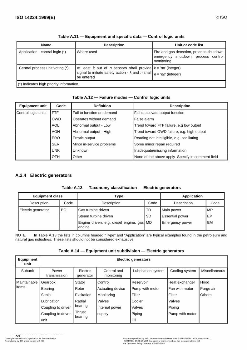
Table A.11 — Equipment unit specific data — Control logic units
Name Description Unit or code list
Application - control logic (*) Where used Fire and gas detection, process shutdown,emergency shutdown, process control,monitoring
Central process unit voting (*) At least k out of n sensors shall providesignal to initiate safety action - k and n shallbe entered
k = 'nn' (integer)
n = 'nn' (integer)
(*) Indicates high priority information.
Table A.12 — Failure modes — Control logic units
Equipment unit Code Definition Description
Control logic units FTF Fail to function on demand Fail to activate output function
OWD Operates without demand False alarm
AOL Abnormal output - Low Trend toward FTF failure, e.g low output
AOH Abnormal output - High Trend toward OWD failure, e.g. high output
ERO Erratic output Reading not intelligible, e.g. oscillating
SER Minor in-service problems Some minor repair required
UNK Unknown Inadequate/missing information
OTH Other None of the above apply. Specify in comment field
A.2.4 Electric generators
Table A.13 — Taxonomy classification — Electric generators
Equipment class Type Application
Description Code Description Code Description Code
Electric generator EG Gas turbine driven TD Main power MP
Steam turbine driven SD Essential power EP
Engine driven, e.g. diesel engine, gasengine
MD Emergency power EM
NOTE In Table A.13 the lists in columns headed "Type" and "Application" are typical examples found in the petroleum andnatural gas industries. These lists should not be considered exhaustive.
Table A.14 — Equipment unit subdivision — Electric generators
Equipmentunit
Electric generators
Subunit Powertransmission
Electricgenerator
Control andmonitoring
Lubrication system Cooling system Miscellaneous
Maintainableitems
Gearbox
Bearing
Seals
Lubrication
Coupling to driver
Coupling to driven
unit
Stator
Rotor
Excitation
Radialbearing
Thrustbearing
Control
Actuating device
Monitoring
Valves
Internal power
supply
Reservoir
Pump with motor
Filter
Cooler
Valves
Piping
Oil
Heat exchanger
Fan with motor
Filter
Valves
Piping
Pump with motor
Hood
Purge air
Others
Copyright International Organization for Standardization Reproduced by IHS under license with ISO
Document provided by IHS Licensee=Amerada Hess WAN SSPPU/5958418001, User=MHALL, 04/21/2004 19:31:52 MDT Questions or comments about this message: please callthe Document Policy Group at 303-397-2295.
--````,``,,,`,,```,```,`,``,``,`,``````,,`,`,,,`````-`-`,,`,,`,`,,`---
© ISO ISO 14224:1999(E)
23
S T A R T I N GS Y S T E M
D R I V E RP O W E R
T R A N S M I S S I O NE L E C T R I C
G E N E R A T O R
Circui tbreaker
Busbar
C O O L I N G S Y S T E M L U B R I C A T I O N S Y S T E MC O N T R O L A N D
M O N I T O R I N G S Y S T E M
Coolant Coolant Powersupply
Remoteinst rumentat ion
Fuel orE l . Power
Boundary
M I S C E L -L A N E O U S
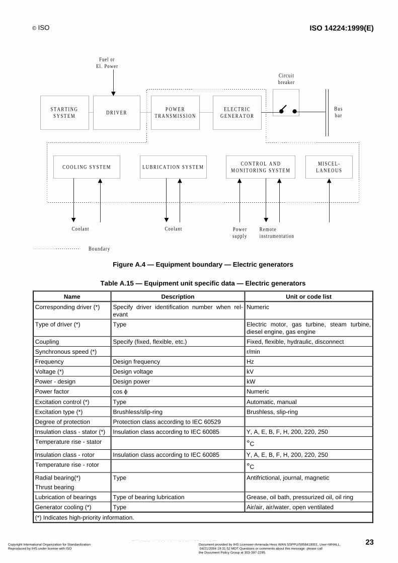
Figure A.4 — Equipment boundary — Electric generators
Table A.15 — Equipment unit specific data — Electric generators
Name Description Unit or code list
Corresponding driver (*) Specify driver identification number when rel-evant
Numeric
Type of driver (*) Type Electric motor, gas turbine, steam turbine,diesel engine, gas engine
Coupling Specify (fixed, flexible, etc.) Fixed, flexible, hydraulic, disconnect
Synchronous speed (*) r/min
Frequency Design frequency Hz
Voltage (*) Design voltage kV
Power - design Design power kW
Power factor cos ϕ Numeric
Excitation control (*) Type Automatic, manual
Excitation type (*) Brushless/slip-ring Brushless, slip-ring
Degree of protection Protection class according to IEC 60529
Insulation class - stator (*) Insulation class according to IEC 60085 Y, A, E, B, F, H, 200, 220, 250
Temperature rise - stator °C
Insulation class - rotor Insulation class according to IEC 60085 Y, A, E, B, F, H, 200, 220, 250
Temperature rise - rotor °C
Radial bearing(*)
Thrust bearing
Type Antifrictional, journal, magnetic
Lubrication of bearings Type of bearing lubrication Grease, oil bath, pressurized oil, oil ring
Generator cooling (*) Type Air/air, air/water, open ventilated
(*) Indicates high-priority information.
Copyright International Organization for Standardization Reproduced by IHS under license with ISO
Document provided by IHS Licensee=Amerada Hess WAN SSPPU/5958418001, User=MHALL, 04/21/2004 19:31:52 MDT Questions or comments about this message: please callthe Document Policy Group at 303-397-2295.
--````,``,,,`,,```,```,`,``,``,`,``````,,`,`,,,`````-`-`,,`,,`,`,,`---
ISO 14224:1999(E) © ISO
24
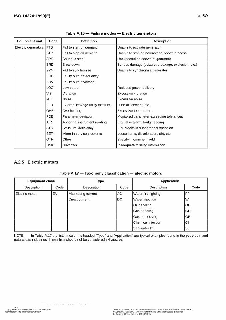
Table A.16 — Failure modes — Electric generators
Equipment unit Code Definition Description
Electric generators FTS Fail to start on demand Unable to activate generator
STP Fail to stop on demand Unable to stop or incorrect shutdown process
SPS Spurious stop Unexpected shutdown of generator
BRD Breakdown Serious damage (seizure, breakage, explosion, etc.)
SYN Fail to synchronise Unable to synchronise generator
FOF Faulty output frequency
FOV Faulty output voltage
LOO Low output Reduced power delivery
VIB Vibration Excessive vibration
NOI Noise Excessive noise
ELU External leakage utility medium Lube oil, coolant, etc.
OHE Overheating Excessive temperature
PDE Parameter deviation Monitored parameter exceeding tolerances
AIR Abnormal instrument reading E.g. false alarm, faulty reading
STD Structural deficiency E.g. cracks in support or suspension
SER Minor in-service problems Loose items, discoloration, dirt, etc.
OTH Other Specify in comment field
UNK Unknown Inadequate/missing information
A.2.5 Electric motors
Table A.17 — Taxonomy classification — Electric motors
Equipment class Type Application
Description Code Description Code Description Code
Electric motor EM Alternating current AC Water fire-fighting FF
Direct current DC Water injection WI
Oil handling OH
Gas handling GH
Gas processing GP
Chemical injection CI
Sea-water lift SL
NOTE In Table A.17 the lists in columns headed "Type" and "Application" are typical examples found in the petroleum andnatural gas industries. These lists should not be considered exhaustive.
Copyright International Organization for Standardization Reproduced by IHS under license with ISO
Document provided by IHS Licensee=Amerada Hess WAN SSPPU/5958418001, User=MHALL, 04/21/2004 19:31:52 MDT Questions or comments about this message: please callthe Document Policy Group at 303-397-2295.
--````,``,,,`,,```,```,`,``,``,`,``````,,`,`,,,`````-`-`,,`,,`,`,,`---
© ISO ISO 14224:1999(E)
25
Bus
ELECTRIC MOTOR
COOLINGSYSTEM
CONTROL ANDMONITORING
SYSTEM
MISCEL-LANEOUS
Coolant Power Remoteinstrumentation
LUBRICATIONSYSTEM
Coolant
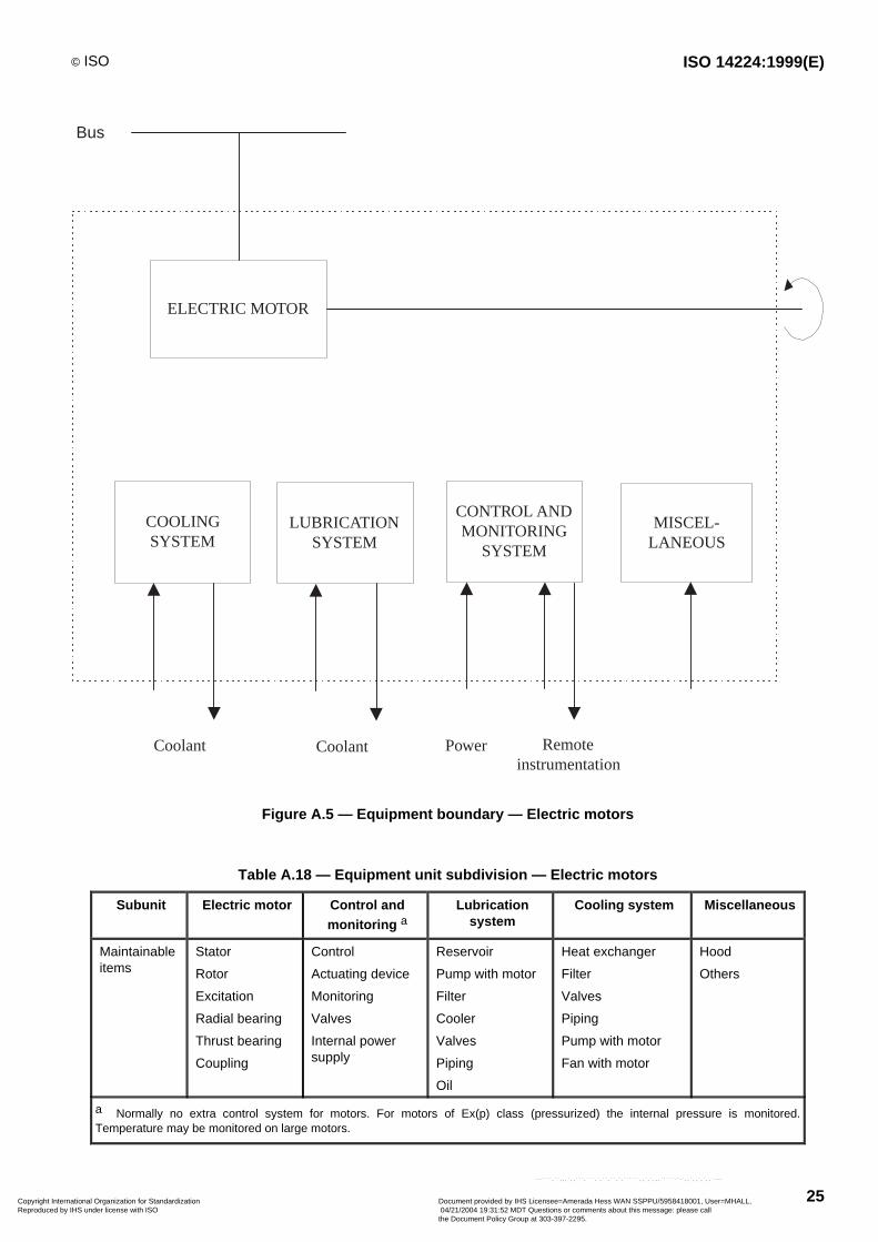
Figure A.5 — Equipment boundary — Electric motors
Table A.18 — Equipment unit subdivision — Electric motors
Subunit Electric motor Control andmonitoring a
Lubricationsystem
Cooling system Miscellaneous
Maintainableitems
Stator
Rotor
Excitation
Radial bearing
Thrust bearing
Coupling
Control
Actuating device
Monitoring
Valves
Internal powersupply
Reservoir
Pump with motor
Filter
Cooler
Valves
Piping
Oil
Heat exchanger
Filter
Valves
Piping
Pump with motor
Fan with motor
Hood
Others
a Normally no extra control system for motors. For motors of Ex(p) class (pressurized) the internal pressure is monitored.Temperature may be monitored on large motors.
Copyright International Organization for Standardization Reproduced by IHS under license with ISO
Document provided by IHS Licensee=Amerada Hess WAN SSPPU/5958418001, User=MHALL, 04/21/2004 19:31:52 MDT Questions or comments about this message: please callthe Document Policy Group at 303-397-2295.
--````,``,,,`,,```,```,`,``,``,`,``````,,`,`,,,`````-`-`,,`,,`,`,,`---
ISO 14224:1999(E) © ISO
26
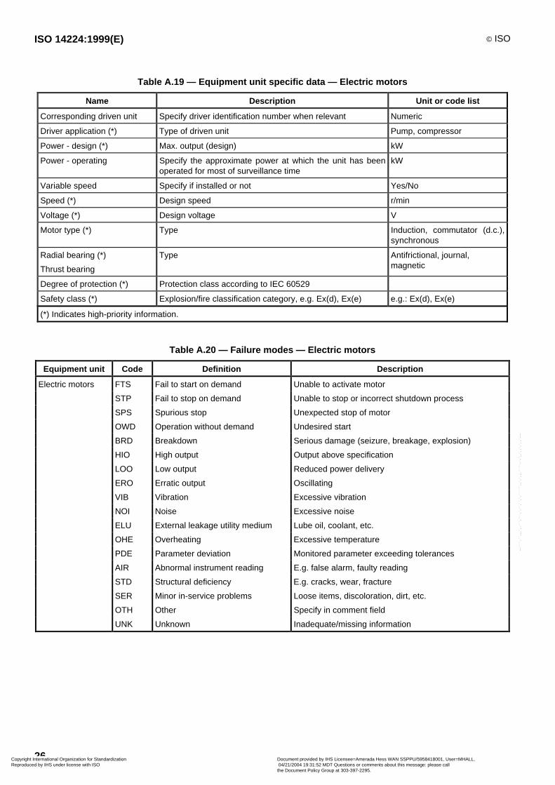
Table A.19 — Equipment unit specific data — Electric motors
Name Description Unit or code list
Corresponding driven unit Specify driver identification number when relevant Numeric
Driver application (*) Type of driven unit Pump, compressor
Power - design (*) Max. output (design) kW
Power - operating Specify the approximate power at which the unit has beenoperated for most of surveillance time
kW
Variable speed Specify if installed or not Yes/No
Speed (*) Design speed r/min
Voltage (*) Design voltage V
Motor type (*) Type Induction, commutator (d.c.),synchronous
Radial bearing (*)
Thrust bearing
Type Antifrictional, journal,magnetic
Degree of protection (*) Protection class according to IEC 60529
Safety class (*) Explosion/fire classification category, e.g. Ex(d), Ex(e) e.g.: Ex(d), Ex(e)
(*) Indicates high-priority information.
Table A.20 — Failure modes — Electric motors
Equipment unit Code Definition Description
Electric motors FTS Fail to start on demand Unable to activate motor
STP Fail to stop on demand Unable to stop or incorrect shutdown process
SPS Spurious stop Unexpected stop of motor
OWD Operation without demand Undesired start
BRD Breakdown Serious damage (seizure, breakage, explosion)
HIO High output Output above specification
LOO Low output Reduced power delivery
ERO Erratic output Oscillating
VIB Vibration Excessive vibration
NOI Noise Excessive noise
ELU External leakage utility medium Lube oil, coolant, etc.
OHE Overheating Excessive temperature
PDE Parameter deviation Monitored parameter exceeding tolerances
AIR Abnormal instrument reading E.g. false alarm, faulty reading
STD Structural deficiency E.g. cracks, wear, fracture
SER Minor in-service problems Loose items, discoloration, dirt, etc.
OTH Other Specify in comment field
UNK Unknown Inadequate/missing information
Copyright International Organization for Standardization Reproduced by IHS under license with ISO
Document provided by IHS Licensee=Amerada Hess WAN SSPPU/5958418001, User=MHALL, 04/21/2004 19:31:52 MDT Questions or comments about this message: please callthe Document Policy Group at 303-397-2295.
--````,``,,,`,,```,```,`,``,``,`,``````,,`,`,,,`````-`-`,,`,,`,`,,`---

© ISO ISO 14224:1999(E)
27
A.2.6 Fire and gas detectors
Table A.21 — Taxonomy classification — Fire and gas detectors
Equipment class Type Application
Description Code Description Code Description Code
Fire and gas detectors FG Smoke/Combustion
Heat
Flame
BS
BH
BF
Fire detection FD
Hydrocarbon
H2S
AB
AS
Gas detection GD
NOTE In Table A.21 the lists in columns headed "Type" and "Application" are typical examples found in the petroleum andnatural gas industries. These lists should not be considered exhaustive.
ControlLogicUnit
A D D R E S S / I N T E R F A C E U N I T
Othersensors
Sensor
Power
Boundary
Figure A.6 — Equipment boundary — Fire and gas detectors
Table A.22 — Equipment unit subdivision — Fire and gas detectors
Equipment unit Fire and gas detectors
Subunit Sensor Interface unit Miscellaneous
Maintainable items Mounting socket
Detector head
Cover
Control card
Display
Cabinet
Cabling
Others
Copyright International Organization for Standardization Reproduced by IHS under license with ISO
Document provided by IHS Licensee=Amerada Hess WAN SSPPU/5958418001, User=MHALL, 04/21/2004 19:31:52 MDT Questions or comments about this message: please callthe Document Policy Group at 303-397-2295.
--````,``,,,`,,```,```,`,``,``,`,``````,,`,`,,,`````-`-`,,`,,`,`,,`---
ISO 14224:1999(E) © ISO
28
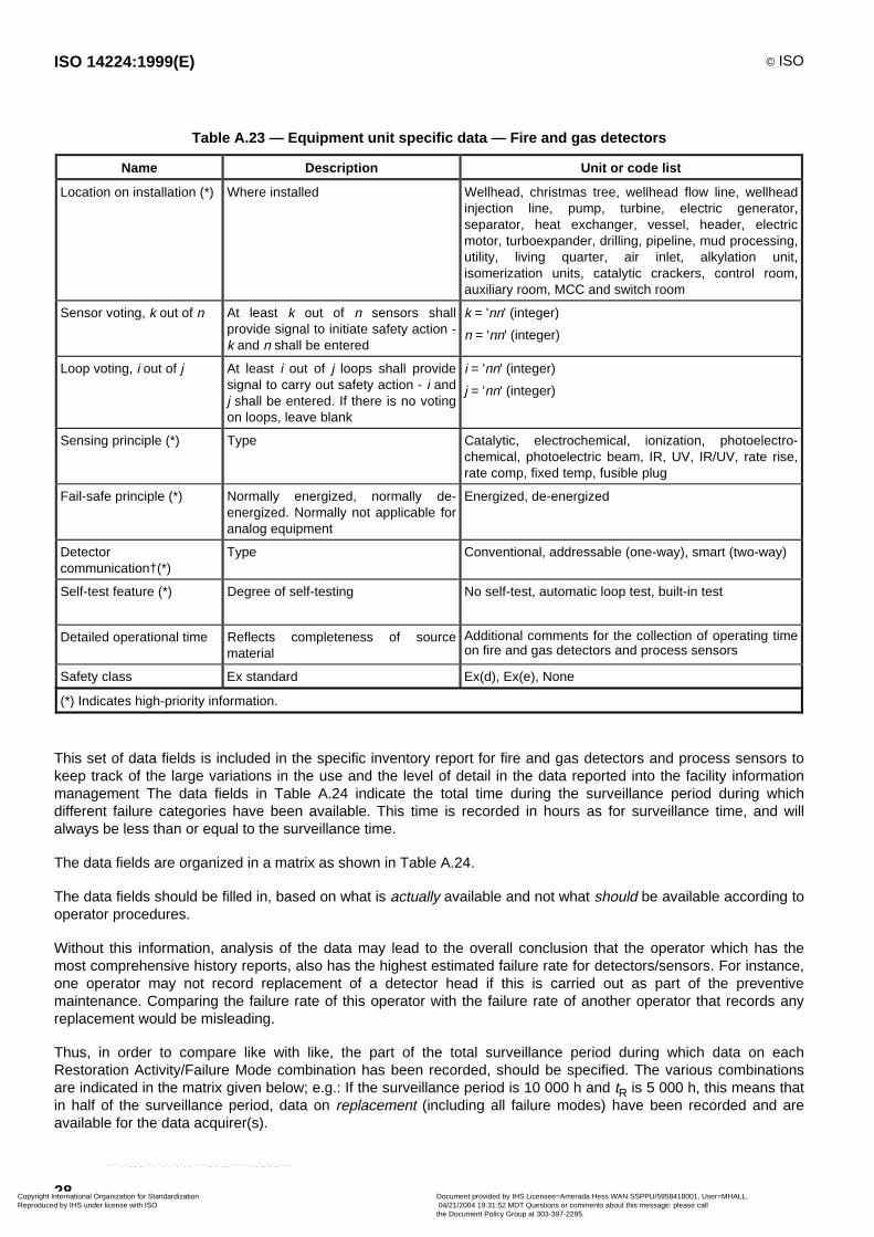
Table A.23 — Equipment unit specific data — Fire and gas detectors
Name Description Unit or code list
Location on installation (*) Where installed Wellhead, christmas tree, wellhead flow line, wellheadinjection line, pump, turbine, electric generator,separator, heat exchanger, vessel, header, electricmotor, turboexpander, drilling, pipeline, mud processing,utility, living quarter, air inlet, alkylation unit,isomerization units, catalytic crackers, control room,auxiliary room, MCC and switch room
Sensor voting, k out of n At least k out of n sensors shallprovide signal to initiate safety action -k and n shall be entered
k = 'nn' (integer)
n = 'nn' (integer)
Loop voting, i out of j At least i out of j loops shall providesignal to carry out safety action - i andj shall be entered. If there is no votingon loops, leave blank
i = 'nn' (integer)
j = 'nn' (integer)
Sensing principle (*) Type Catalytic, electrochemical, ionization, photoelectro-chemical, photoelectric beam, IR, UV, IR/UV, rate rise,rate comp, fixed temp, fusible plug
Fail-safe principle (*) Normally energized, normally de-energized. Normally not applicable foranalog equipment
Energized, de-energized
Detectorcommunication†(*)
Type Conventional, addressable (one-way), smart (two-way)
Self-test feature (*) Degree of self-testing No self-test, automatic loop test, built-in test
Detailed operational time Reflects completeness of sourcematerial
Additional comments for the collection of operating timeon fire and gas detectors and process sensors
Safety class Ex standard Ex(d), Ex(e), None
(*) Indicates high-priority information.
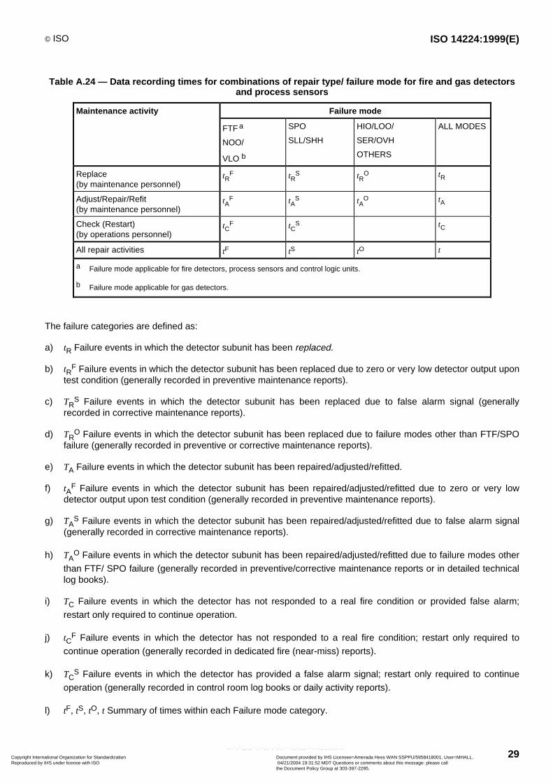
This set of data fields is included in the specific inventory report for fire and gas detectors and process sensors tokeep track of the large variations in the use and the level of detail in the data reported into the facility informationmanagement The data fields in Table A.24 indicate the total time during the surveillance period during whichdifferent failure categories have been available. This time is recorded in hours as for surveillance time, and willalways be less than or equal to the surveillance time.
The data fields are organized in a matrix as shown in Table A.24.
The data fields should be filled in, based on what is actually available and not what should be available according tooperator procedures.
Without this information, analysis of the data may lead to the overall conclusion that the operator which has themost comprehensive history reports, also has the highest estimated failure rate for detectors/sensors. For instance,one operator may not record replacement of a detector head if this is carried out as part of the preventivemaintenance. Comparing the failure rate of this operator with the failure rate of another operator that records anyreplacement would be misleading.
Thus, in order to compare like with like, the part of the total surveillance period during which data on eachRestoration Activity/Failure Mode combination has been recorded, should be specified. The various combinationsare indicated in the matrix given below; e.g.: If the surveillance period is 10 000 h and tR is 5 000 h, this means thatin half of the surveillance period, data on replacement (including all failure modes) have been recorded and areavailable for the data acquirer(s).
Copyright International Organization for Standardization Reproduced by IHS under license with ISO
Document provided by IHS Licensee=Amerada Hess WAN SSPPU/5958418001, User=MHALL, 04/21/2004 19:31:52 MDT Questions or comments about this message: please callthe Document Policy Group at 303-397-2295.
--````,``,,,`,,```,```,`,``,``,`,``````,,`,`,,,`````-`-`,,`,,`,`,,`---
© ISO ISO 14224:1999(E)
29
Table A.24 — Data recording times for combinations of repair type/ failure mode for fire and gas detectorsand process sensors
Maintenance activity Failure mode
FTF a
NOO/
VLO b
SPO
SLL/SHH
HIO/LOO/
SER/OVH
OTHERS
ALL MODES
Replace(by maintenance personnel)
tRF tR
S tRO tR
Adjust/Repair/Refit(by maintenance personnel)
tAF tA
S tAO tA
Check (Restart)(by operations personnel)
tCF tC
S tC
All repair activities tF tS tO t
a Failure mode applicable for fire detectors, process sensors and control logic units.
b Failure mode applicable for gas detectors.
The failure categories are defined as:
a) tR Failure events in which the detector subunit has been replaced.
b) tRF Failure events in which the detector subunit has been replaced due to zero or very low detector output upon
test condition (generally recorded in preventive maintenance reports).
c) TRS Failure events in which the detector subunit has been replaced due to false alarm signal (generally
recorded in corrective maintenance reports).
d) TRO Failure events in which the detector subunit has been replaced due to failure modes other than FTF/SPO
failure (generally recorded in preventive or corrective maintenance reports).
e) TA Failure events in which the detector subunit has been repaired/adjusted/refitted.
f) tAF Failure events in which the detector subunit has been repaired/adjusted/refitted due to zero or very low
detector output upon test condition (generally recorded in preventive maintenance reports).
g) TAS Failure events in which the detector subunit has been repaired/adjusted/refitted due to false alarm signal
(generally recorded in corrective maintenance reports).
h) TAO Failure events in which the detector subunit has been repaired/adjusted/refitted due to failure modes other
than FTF/ SPO failure (generally recorded in preventive/corrective maintenance reports or in detailed technicallog books).
i) TC Failure events in which the detector has not responded to a real fire condition or provided false alarm;
restart only required to continue operation.
j) tCF Failure events in which the detector has not responded to a real fire condition; restart only required to
continue operation (generally recorded in dedicated fire (near-miss) reports).
k) TCS Failure events in which the detector has provided a false alarm signal; restart only required to continue
operation (generally recorded in control room log books or daily activity reports).
l) tF, tS, tO, t Summary of times within each Failure mode category.
Copyright International Organization for Standardization Reproduced by IHS under license with ISO
Document provided by IHS Licensee=Amerada Hess WAN SSPPU/5958418001, User=MHALL, 04/21/2004 19:31:52 MDT Questions or comments about this message: please callthe Document Policy Group at 303-397-2295.
--````,``,,,`,,```,```,`,``,``,`,``````,,`,`,,,`````-`-`,,`,,`,`,,`---
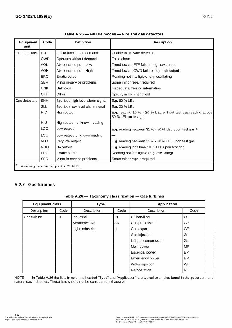
ISO 14224:1999(E) © ISO
30
Table A.25 — Failure modes — Fire and gas detectors
Equipmentunit
Code Definition Description
Fire detectors FTF Fail to function on demand Unable to activate detector
OWD Operates without demand False alarm
AOL Abnormal output - Low Trend toward FTF failure, e.g. low output
AOH Abnormal output - High Trend toward OWD failure, e.g. high output
ERO Erratic output Reading not intelligible, e.g. oscillating
SER Minor in-service problems Some minor repair required
UNK Unknown Inadequate/missing information
OTH Other Specify in comment field
Gas detectors SHH Spurious high level alarm signal E.g. 60 % LEL
SLL Spurious low level alarm signal E.g. 20 % LEL
HIO High output E.g. reading 10 % - 20 % LEL without test gas/reading above80 % LEL on test gas
HIU High output, unknown reading —
LOO Low output E.g. reading between 31 % - 50 % LEL upon test gas a
LOU Low output, unknown reading —
VLO Very low output E.g. reading between 11 % - 30 % LEL upon test gas
NOO No output E.g. reading less than 10 % LEL upon test gas
ERO Erratic output Reading not intelligible (e.g. oscillating)
SER Minor in-service problems Some minor repair required
a Assuming a nominal set point of 65 % LEL.
A.2.7 Gas turbines
Table A.26 — Taxonomy classification — Gas turbines
Equipment class Type Application
Description Code Description Code Description Code
Gas turbine GT Industrial IN Oil handling OH
Aeroderivative AD Gas processing GP
Light industrial LI Gas export GE
Gas injection GI
Lift gas compression GL
Main power MP
Essential power EP
Emergency power EM
Water injection WI
Refrigeration RE
NOTE In Table A.26 the lists in columns headed "Type" and "Application" are typical examples found in the petroleum andnatural gas industries. These lists should not be considered exhaustive.
Copyright International Organization for Standardization Reproduced by IHS under license with ISO
Document provided by IHS Licensee=Amerada Hess WAN SSPPU/5958418001, User=MHALL, 04/21/2004 19:31:52 MDT Questions or comments about this message: please callthe Document Policy Group at 303-397-2295.
--````,``,,,`,,```,```,`,``,``,`,``````,,`,`,,,`````-`-`,,`,,`,`,,`---
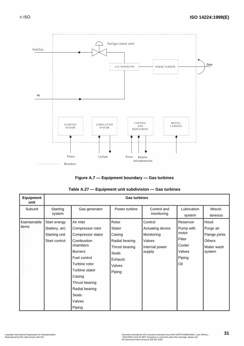
© ISO ISO 14224:1999(E)
31
S T A R T I N GS Y S T E M
L U B R I C A T I O NS Y S T E M
C O N T R O LA N D
M O N I T O R I N G
M I S C E L -L A N E O U S
G A S G E N E R A T O R P O W E R T U R B I N EDrive
Fuel /gas contro l valve
Fuel /Gas
Coolant Power Remoteinst rumentat ion
Boundary
Air
Power
Figure A.7 — Equipment boundary — Gas turbines
Table A.27 — Equipment unit subdivision — Gas turbines
Equipmentunit
Gas turbines
Subunit Startingsystem
Gas generator Power turbine Control andmonitoring
Lubrication
system
Miscel-
laneous
Maintainableitems
Start energy
(battery, air)
Starting unit
Start control
Air inlet
Compressor rotor
Compressor stator
Combustionchambers
Burners
Fuel control
Turbine rotor
Turbine stator
Casing
Thrust bearing
Radial bearing
Seals
Valves
Piping
Rotor
Stator
Casing
Radial bearing
Thrust bearing
Seals
Exhaust
Valves
Piping
Control
Actuating device
Monitoring
Valves
Internal powersupply
Reservoir
Pump withmotor
Filter
Cooler
Valves
Piping
Oil
Hood
Purge air
Flange joints
Others
Water washsystem
Copyright International Organization for Standardization Reproduced by IHS under license with ISO
Document provided by IHS Licensee=Amerada Hess WAN SSPPU/5958418001, User=MHALL, 04/21/2004 19:31:52 MDT Questions or comments about this message: please callthe Document Policy Group at 303-397-2295.
--````,``,,,`,,```,```,`,``,``,`,``````,,`,`,,,`````-`-`,,`,,`,`,,`---
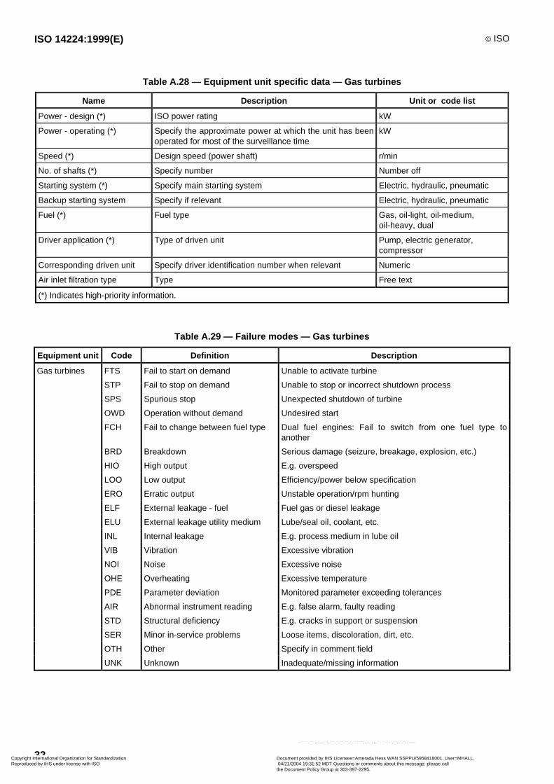
ISO 14224:1999(E) © ISO
32
Table A.28 — Equipment unit specific data — Gas turbines
Name Description Unit or code list
Power - design (*) ISO power rating kW
Power - operating (*) Specify the approximate power at which the unit has beenoperated for most of the surveillance time
kW
Speed (*) Design speed (power shaft) r/min
No. of shafts (*) Specify number Number off
Starting system (*) Specify main starting system Electric, hydraulic, pneumatic
Backup starting system Specify if relevant Electric, hydraulic, pneumatic
Fuel (*) Fuel type Gas, oil-light, oil-medium,oil-heavy, dual
Driver application (*) Type of driven unit Pump, electric generator,compressor
Corresponding driven unit Specify driver identification number when relevant Numeric
Air inlet filtration type Type Free text
(*) Indicates high-priority information.
Table A.29 — Failure modes — Gas turbines
Equipment unit Code Definition Description
Gas turbines FTS Fail to start on demand Unable to activate turbine
STP Fail to stop on demand Unable to stop or incorrect shutdown process
SPS Spurious stop Unexpected shutdown of turbine
OWD Operation without demand Undesired start
FCH Fail to change between fuel type Dual fuel engines: Fail to switch from one fuel type toanother
BRD Breakdown Serious damage (seizure, breakage, explosion, etc.)
HIO High output E.g. overspeed
LOO Low output Efficiency/power below specification
ERO Erratic output Unstable operation/rpm hunting
ELF External leakage - fuel Fuel gas or diesel leakage
ELU External leakage utility medium Lube/seal oil, coolant, etc.
INL Internal leakage E.g. process medium in lube oil
VIB Vibration Excessive vibration
NOI Noise Excessive noise
OHE Overheating Excessive temperature
PDE Parameter deviation Monitored parameter exceeding tolerances
AIR Abnormal instrument reading E.g. false alarm, faulty reading
STD Structural deficiency E.g. cracks in support or suspension
SER Minor in-service problems Loose items, discoloration, dirt, etc.
OTH Other Specify in comment field
UNK Unknown Inadequate/missing information
Copyright International Organization for Standardization Reproduced by IHS under license with ISO
Document provided by IHS Licensee=Amerada Hess WAN SSPPU/5958418001, User=MHALL, 04/21/2004 19:31:52 MDT Questions or comments about this message: please callthe Document Policy Group at 303-397-2295.
--````,``,,,`,,```,```,`,``,``,`,``````,,`,`,,,`````-`-`,,`,,`,`,,`---
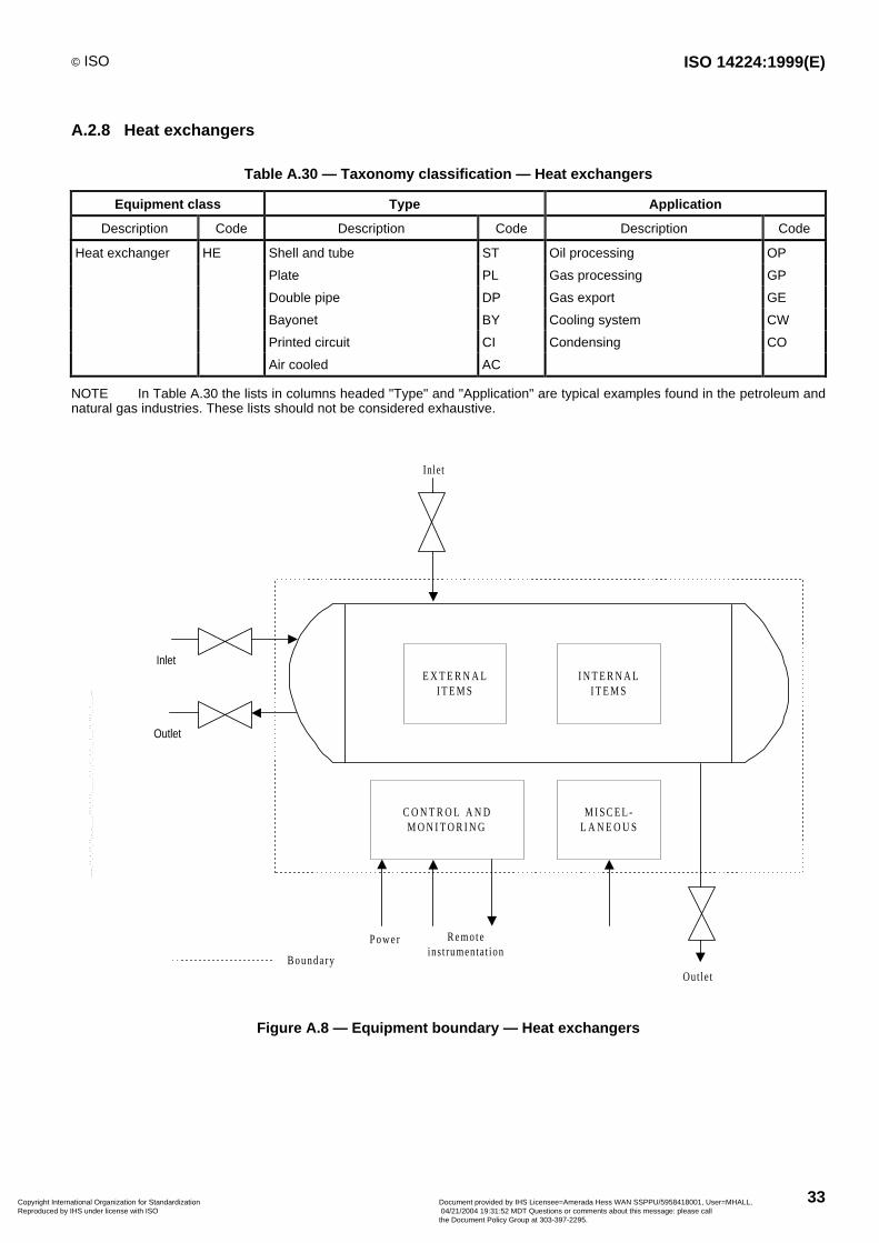
© ISO ISO 14224:1999(E)
33
A.2.8 Heat exchangers
Table A.30 — Taxonomy classification — Heat exchangers
Equipment class Type Application
Description Code Description Code Description Code
Heat exchanger HE Shell and tube ST Oil processing OP
Plate PL Gas processing GP
Double pipe DP Gas export GE
Bayonet BY Cooling system CW
Printed circuit CI Condensing CO
Air cooled AC
NOTE In Table A.30 the lists in columns headed "Type" and "Application" are typical examples found in the petroleum andnatural gas industries. These lists should not be considered exhaustive.
Inlet
C O N T R O L A N DM O N I T O R I N G
Power Remoteinst rumentat ion
Boundary
Outlet
Inlet
Out let
M I S C E L -L A N E O U S
E X T E R N A LI T E M S
I N T E R N A LI T E M S
Figure A.8 — Equipment boundary — Heat exchangers
Copyright International Organization for Standardization Reproduced by IHS under license with ISO
Document provided by IHS Licensee=Amerada Hess WAN SSPPU/5958418001, User=MHALL, 04/21/2004 19:31:52 MDT Questions or comments about this message: please callthe Document Policy Group at 303-397-2295.
--````,``,,,`,,```,```,`,``,``,`,``````,,`,`,,,`````-`-`,,`,,`,`,,`---

ISO 14224:1999(E) © ISO
34
Table A.31 — Equipment unit subdivision — Heat exchangers
Equipment unit Heat exchangers
Subunit External Internal Control and monitoring Miscellaneous
Maintainable items Support
Body/shell
Valves
Piping
Body/shell
Tubes
Plates
Seals (gaskets)
Control
Actuating device
Monitoring
Valves
Internal power supply
Fan a
Fan motor
Others
a Applicable for air cooled heat exchangers only.
Table A.32 — Equipment unit specific data — Heat exchangers
Name Description Unit or code list
Fluid, hot side (*) Fluid type E.g. oil, gas, condensate, freshwater, steam, sea water,crude oil, oily water, flare gas, water/glycol, methanol,nitrogen, chemicals, hydrocarbon, air
Fluid, cold side (*) Fluid type E.g. oil, gas, condensate, freshwater, steam, sea water,crude oil, oily water, flare gas, water/glycol, methanol,nitrogen, chemicals, hydrocarbon, air
Rated heat transfer (*) Design value kW
Utilisation (*) Used/rated heat transfer %
Pressure, hot side (*) Design pressure pascal (bar)
Pressure, cold side (*) Design pressure pascal (bar)
Temperature drop, hot side Operating °C
Temperature rise, cold side Operating °C
Size - diameter (*) External mm
Size - length (*) External mm
Number of tubes/plates Numeric
Tube/plate material (*) Specify material type in tubes/plates Free text
(*) Indicates high-priority information.
Table A.33 — Failure modes — Heat exchangers
Equipment unit Code Definition Description
Heat exchangers IHT Insufficient heat transfer Insufficient heating/cooling
ELP External leakage process medium Process medium escape to environment
ELU External leakage utility medium Coolant escape to environment
INL Internal leakage Hot/cold side communication
PLU Plugged/choked Partial or full flow restriction due to hydrate, wax, scale, etc.
STD Structural deficiency Reduced strength due to impact, unacceptable corrosion,cracks, etc.
PDE Parameter deviation Monitored parameter exceeding tolerances
AIR Abnormal instrument reading E.g. false alarm, faulty reading
SER Minor in-service problems Loose items, discoloration, dirt, etc.
OTH Other Specify in comment field
UNK Unknown Inadequate/missing information
Copyright International Organization for Standardization Reproduced by IHS under license with ISO
Document provided by IHS Licensee=Amerada Hess WAN SSPPU/5958418001, User=MHALL, 04/21/2004 19:31:52 MDT Questions or comments about this message: please callthe Document Policy Group at 303-397-2295.
--````,``,,,`,,```,```,`,``,``,`,``````,,`,`,,,`````-`-`,,`,,`,`,,`---
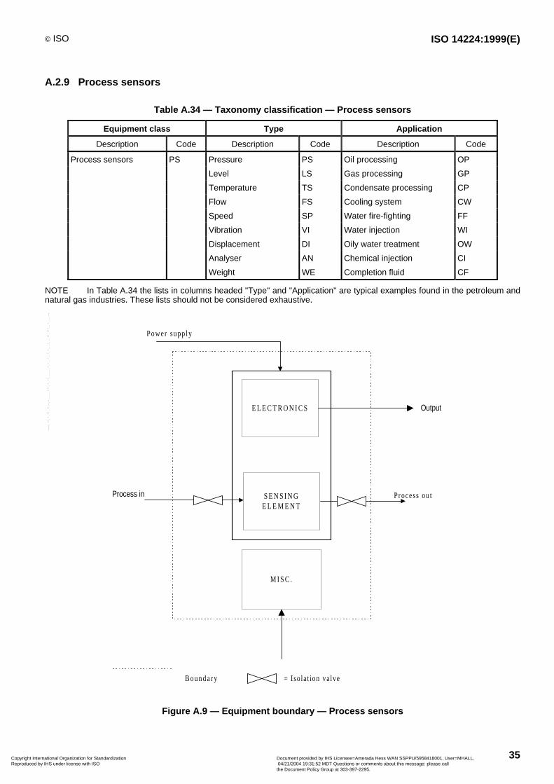
© ISO ISO 14224:1999(E)
35
A.2.9 Process sensors
Table A.34 — Taxonomy classification — Process sensors
Equipment class Type Application
Description Code Description Code Description Code
Process sensors PS Pressure PS Oil processing OP
Level LS Gas processing GP
Temperature TS Condensate processing CP
Flow FS Cooling system CW
Speed SP Water fire-fighting FF
Vibration VI Water injection WI
Displacement DI Oily water treatment OW
Analyser AN Chemical injection CI
Weight WE Completion fluid CF
NOTE In Table A.34 the lists in columns headed "Type" and "Application" are typical examples found in the petroleum andnatural gas industries. These lists should not be considered exhaustive.
E L E C T R O N I C S
S E N S I N GE L E M E N T
Output
Process outProcess in
Power supp ly
= Iso lat ion valveBounda ry
M I S C .
Figure A.9 — Equipment boundary — Process sensors
Copyright International Organization for Standardization Reproduced by IHS under license with ISO
Document provided by IHS Licensee=Amerada Hess WAN SSPPU/5958418001, User=MHALL, 04/21/2004 19:31:52 MDT Questions or comments about this message: please callthe Document Policy Group at 303-397-2295.
--````,``,,,`,,```,```,`,``,``,`,``````,,`,`,,,`````-`-`,,`,,`,`,,`---
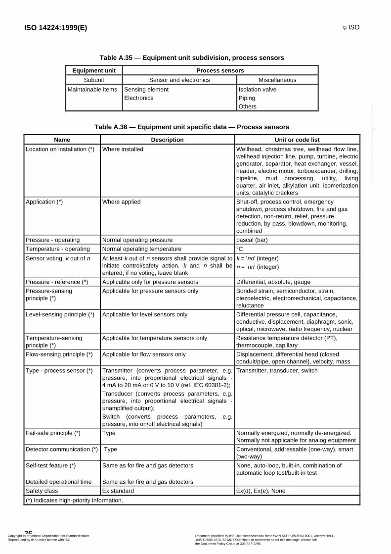
ISO 14224:1999(E) © ISO
36
Table A.35 — Equipment unit subdivision, process sensors
Equipment unit Process sensors
Subunit Sensor and electronics Miscellaneous
Maintainable items Sensing elementElectronics
Isolation valvePipingOthers
Table A.36 — Equipment unit specific data — Process sensors
Name Description Unit or code list
Location on installation (*) Where installed Wellhead, christmas tree, wellhead flow line,wellhead injection line, pump, turbine, electricgenerator, separator, heat exchanger, vessel,header, electric motor, turboexpander, drilling,pipeline, mud processing, utility, livingquarter, air inlet, alkylation unit, isomerizationunits, catalytic crackers
Application (*) Where applied Shut-off, process control, emergencyshutdown, process shutdown, fire and gasdetection, non-return, relief, pressurereduction, by-pass, blowdown, monitoring,combined
Pressure - operating Normal operating pressure pascal (bar)
Temperature - operating Normal operating temperature °CSensor voting, k out of n At least k out of n sensors shall provide signal to
initiate control/safety action. k and n shall beentered; if no voting, leave blank
k = 'nn' (integer)
n = 'nn' (integer)
Pressure - reference (*) Applicable only for pressure sensors Differential, absolute, gauge
Pressure-sensingprinciple (*)
Applicable for pressure sensors only Bonded strain, semiconductor, strain,piezoelectric, electromechanical, capacitance,reluctance
Level-sensing principle (*) Applicable for level sensors only Differential pressure cell, capacitance,conductive, displacement, diaphragm, sonic,optical, microwave, radio frequency, nuclear
Temperature-sensingprinciple (*)
Applicable for temperature sensors only Resistance temperature detector (PT),thermocouple, capillary
Flow-sensing principle (*) Applicable for flow sensors only Displacement, differential head (closedconduit/pipe, open channel), velocity, mass
Type - process sensor (*) Transmitter (converts process parameter, e.g.pressure, into proportional electrical signals -4 mA to 20 mA or 0 V to 10 V (ref. IEC 60381-2);Transducer (converts process parameters, e.g.pressure, into proportional electrical signals -unamplified output);Switch (converts process parameters, e.g.pressure, into on/off electrical signals)
Transmitter, transducer, switch
Fail-safe principle (*) Type Normally energized, normally de-energized.Normally not applicable for analog equipment
Detector communication (*) Type Conventional, addressable (one-way), smart(two-way)
Self-test feature (*) Same as for fire and gas detectors None, auto-loop, built-in, combination ofautomatic loop test/built-in test
Detailed operational time Same as for fire and gas detectors
Safety class Ex standard Ex(d), Ex(e), None
(*) Indicates high-priority information.
Copyright International Organization for Standardization Reproduced by IHS under license with ISO
Document provided by IHS Licensee=Amerada Hess WAN SSPPU/5958418001, User=MHALL, 04/21/2004 19:31:52 MDT Questions or comments about this message: please callthe Document Policy Group at 303-397-2295.
--````,``,,,`,,```,```,`,``,``,`,``````,,`,`,,,`````-`-`,,`,,`,`,,`---
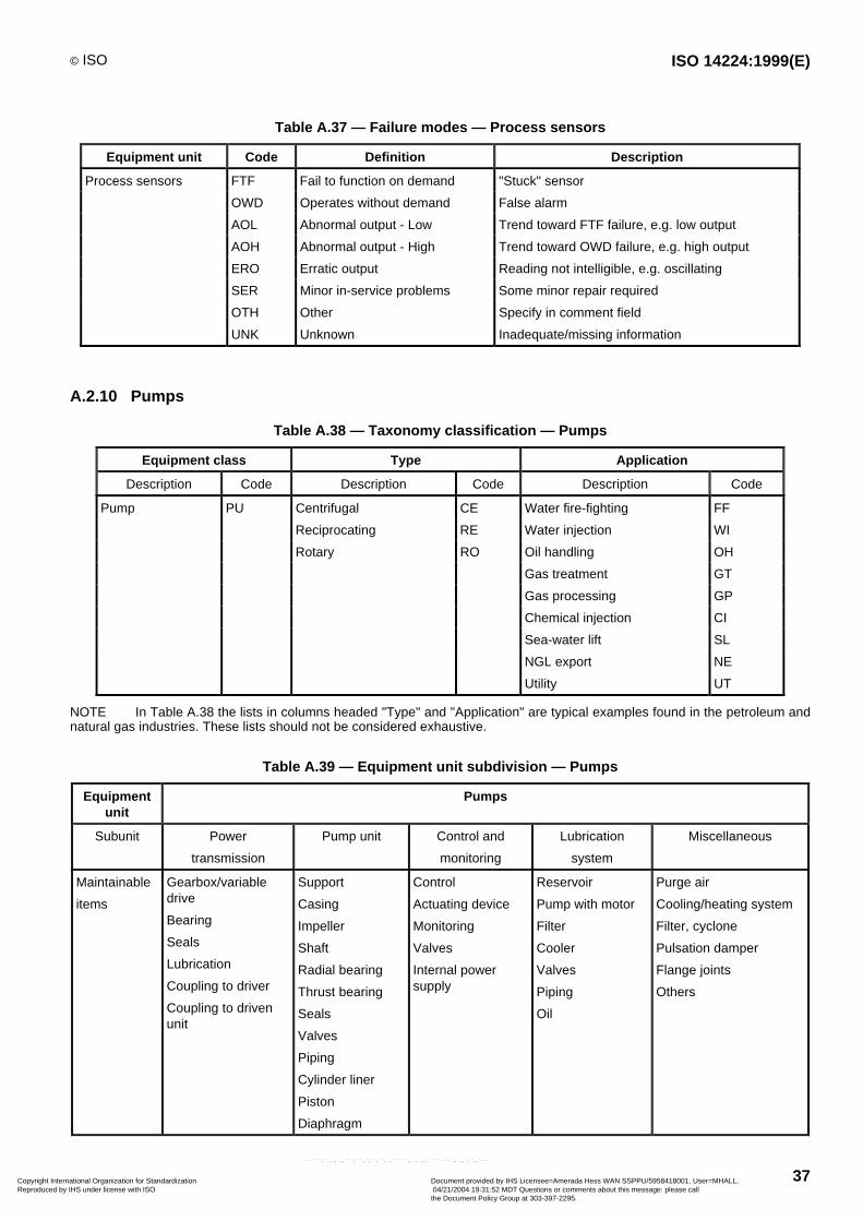
© ISO ISO 14224:1999(E)
37
Table A.37 — Failure modes — Process sensors
Equipment unit Code Definition Description
Process sensors FTF Fail to function on demand "Stuck" sensor
OWD Operates without demand False alarm
AOL Abnormal output - Low Trend toward FTF failure, e.g. low output
AOH Abnormal output - High Trend toward OWD failure, e.g. high output
ERO Erratic output Reading not intelligible, e.g. oscillating
SER Minor in-service problems Some minor repair required
OTH Other Specify in comment field
UNK Unknown Inadequate/missing information
A.2.10 Pumps
Table A.38 — Taxonomy classification — Pumps
Equipment class Type Application
Description Code Description Code Description Code
Pump PU Centrifugal CE Water fire-fighting FF
Reciprocating RE Water injection WI
Rotary RO Oil handling OH
Gas treatment GT
Gas processing GP
Chemical injection CI
Sea-water lift SL
NGL export NE
Utility UT
NOTE In Table A.38 the lists in columns headed "Type" and "Application" are typical examples found in the petroleum andnatural gas industries. These lists should not be considered exhaustive.
Table A.39 — Equipment unit subdivision — Pumps
Equipmentunit
Pumps
Subunit Power
transmission
Pump unit Control and
monitoring
Lubrication
system
Miscellaneous
Maintainable
items
Gearbox/variabledrive
Bearing
Seals
Lubrication
Coupling to driver
Coupling to drivenunit
Support
Casing
Impeller
Shaft
Radial bearing
Thrust bearing
Seals
Valves
Piping
Cylinder liner
Piston
Diaphragm
Control
Actuating device
Monitoring
Valves
Internal powersupply
Reservoir
Pump with motor
Filter
Cooler
Valves
Piping
Oil
Purge air
Cooling/heating system
Filter, cyclone
Pulsation damper
Flange joints
Others
Copyright International Organization for Standardization Reproduced by IHS under license with ISO
Document provided by IHS Licensee=Amerada Hess WAN SSPPU/5958418001, User=MHALL, 04/21/2004 19:31:52 MDT Questions or comments about this message: please callthe Document Policy Group at 303-397-2295.
--````,``,,,`,,```,```,`,``,``,`,``````,,`,`,,,`````-`-`,,`,,`,`,,`---
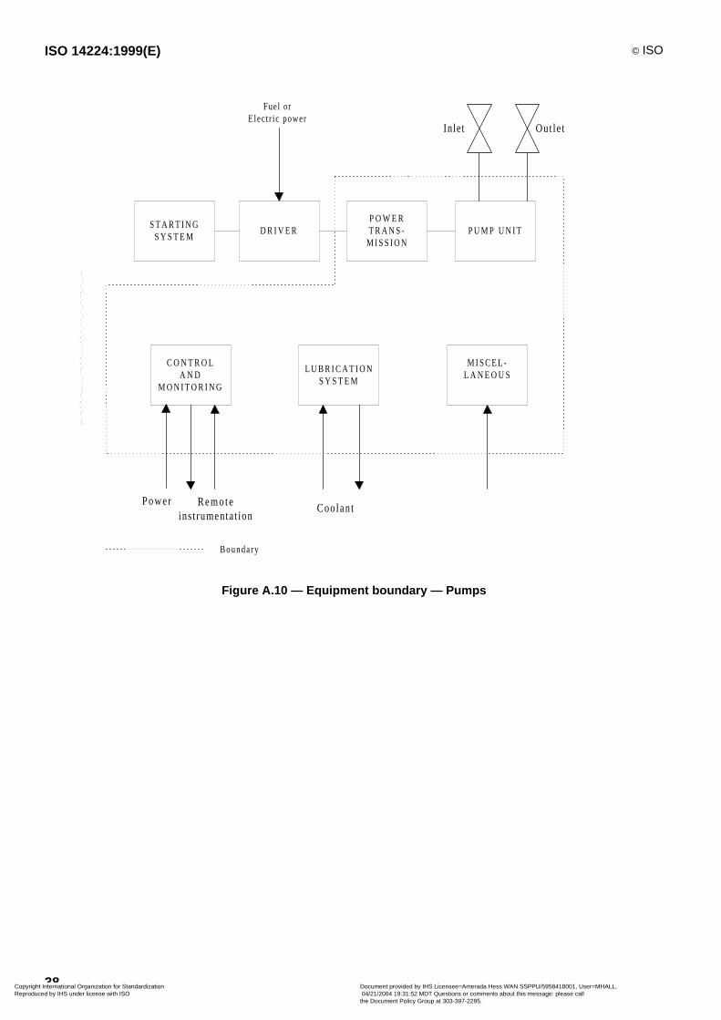
ISO 14224:1999(E) © ISO
38
S T A R T I N GS Y S T E M
D R I V E RP O W E RT R A N S -
M I S S I O NP U M P U N I T
Fuel orElect r ic power
C O N T R O LA N D
M O N I T O R I N G
L U B R I C A T I O NS Y S T E M
M I S C E L -L A N E O U S
Boundary
Power Remoteinst rumentat ion
Coo lant
Inlet Out le t
Figure A.10 — Equipment boundary — Pumps
Copyright International Organization for Standardization Reproduced by IHS under license with ISO
Document provided by IHS Licensee=Amerada Hess WAN SSPPU/5958418001, User=MHALL, 04/21/2004 19:31:52 MDT Questions or comments about this message: please callthe Document Policy Group at 303-397-2295.
--````,``,,,`,,```,```,`,``,``,`,``````,,`,`,,,`````-`-`,,`,,`,`,,`---
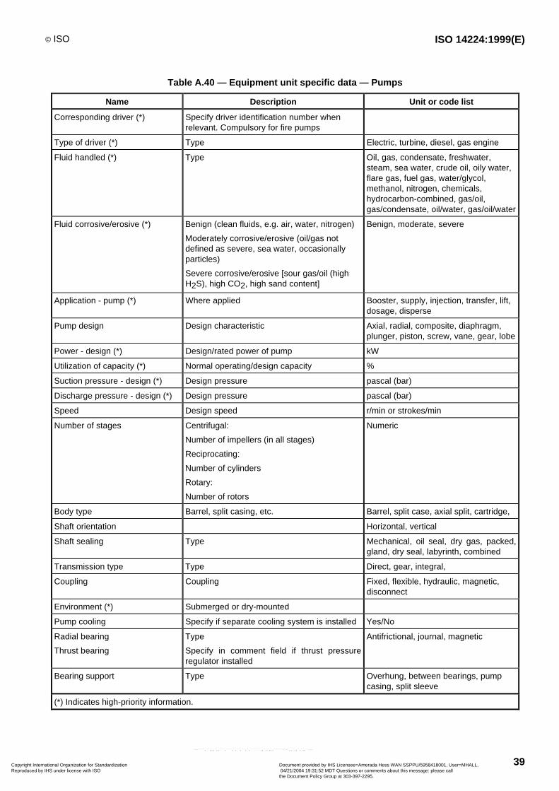
© ISO ISO 14224:1999(E)
39
Table A.40 — Equipment unit specific data — Pumps
Name Description Unit or code list
Corresponding driver (*) Specify driver identification number whenrelevant. Compulsory for fire pumps
Type of driver (*) Type Electric, turbine, diesel, gas engine
Fluid handled (*) Type Oil, gas, condensate, freshwater,steam, sea water, crude oil, oily water,flare gas, fuel gas, water/glycol,methanol, nitrogen, chemicals,hydrocarbon-combined, gas/oil,gas/condensate, oil/water, gas/oil/water
Fluid corrosive/erosive (*) Benign (clean fluids, e.g. air, water, nitrogen)
Moderately corrosive/erosive (oil/gas notdefined as severe, sea water, occasionallyparticles)
Severe corrosive/erosive [sour gas/oil (highH2S), high CO2, high sand content]
Benign, moderate, severe
Application - pump (*) Where applied Booster, supply, injection, transfer, lift,dosage, disperse
Pump design Design characteristic Axial, radial, composite, diaphragm,plunger, piston, screw, vane, gear, lobe
Power - design (*) Design/rated power of pump kW
Utilization of capacity (*) Normal operating/design capacity %
Suction pressure - design (*) Design pressure pascal (bar)
Discharge pressure - design (*) Design pressure pascal (bar)
Speed Design speed r/min or strokes/min
Number of stages Centrifugal:
Number of impellers (in all stages)
Reciprocating:
Number of cylinders
Rotary:
Number of rotors
Numeric
Body type Barrel, split casing, etc. Barrel, split case, axial split, cartridge,
Shaft orientation Horizontal, vertical
Shaft sealing Type Mechanical, oil seal, dry gas, packed,gland, dry seal, labyrinth, combined
Transmission type Type Direct, gear, integral,
Coupling Coupling Fixed, flexible, hydraulic, magnetic,disconnect
Environment (*) Submerged or dry-mounted
Pump cooling Specify if separate cooling system is installed Yes/No
Radial bearing
Thrust bearing
Type
Specify in comment field if thrust pressureregulator installed
Antifrictional, journal, magnetic
Bearing support Type Overhung, between bearings, pumpcasing, split sleeve
(*) Indicates high-priority information.
Copyright International Organization for Standardization Reproduced by IHS under license with ISO
Document provided by IHS Licensee=Amerada Hess WAN SSPPU/5958418001, User=MHALL, 04/21/2004 19:31:52 MDT Questions or comments about this message: please callthe Document Policy Group at 303-397-2295.
--````,``,,,`,,```,```,`,``,``,`,``````,,`,`,,,`````-`-`,,`,,`,`,,`---
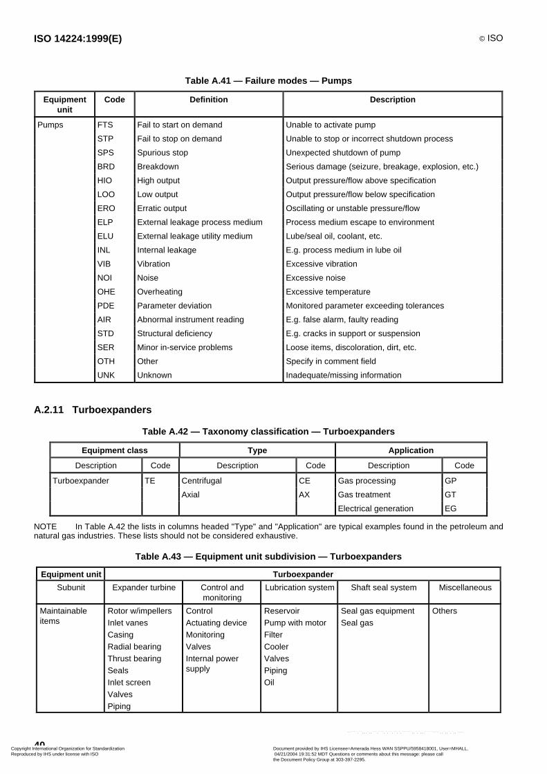
ISO 14224:1999(E) © ISO
40
Table A.41 — Failure modes — Pumps
Equipmentunit
Code Definition Description
Pumps FTS Fail to start on demand Unable to activate pump
STP Fail to stop on demand Unable to stop or incorrect shutdown process
SPS Spurious stop Unexpected shutdown of pump
BRD Breakdown Serious damage (seizure, breakage, explosion, etc.)
HIO High output Output pressure/flow above specification
LOO Low output Output pressure/flow below specification
ERO Erratic output Oscillating or unstable pressure/flow
ELP External leakage process medium Process medium escape to environment
ELU External leakage utility medium Lube/seal oil, coolant, etc.
INL Internal leakage E.g. process medium in lube oil
VIB Vibration Excessive vibration
NOI Noise Excessive noise
OHE Overheating Excessive temperature
PDE Parameter deviation Monitored parameter exceeding tolerances
AIR Abnormal instrument reading E.g. false alarm, faulty reading
STD Structural deficiency E.g. cracks in support or suspension
SER Minor in-service problems Loose items, discoloration, dirt, etc.
OTH Other Specify in comment field
UNK Unknown Inadequate/missing information
A.2.11 Turboexpanders
Table A.42 — Taxonomy classification — Turboexpanders
Equipment class Type Application
Description Code Description Code Description Code
Turboexpander TE Centrifugal CE Gas processing GP
Axial AX Gas treatment GT
Electrical generation EG
NOTE In Table A.42 the lists in columns headed "Type" and "Application" are typical examples found in the petroleum andnatural gas industries. These lists should not be considered exhaustive.
Table A.43 — Equipment unit subdivision — Turboexpanders
Equipment unit Turboexpander
Subunit Expander turbine Control andmonitoring
Lubrication system Shaft seal system Miscellaneous
Maintainableitems
Rotor w/impellersInlet vanesCasingRadial bearingThrust bearingSealsInlet screenValvesPiping
ControlActuating deviceMonitoringValvesInternal powersupply
ReservoirPump with motorFilterCoolerValvesPipingOil
Seal gas equipmentSeal gas
Others
Copyright International Organization for Standardization Reproduced by IHS under license with ISO
Document provided by IHS Licensee=Amerada Hess WAN SSPPU/5958418001, User=MHALL, 04/21/2004 19:31:52 MDT Questions or comments about this message: please callthe Document Policy Group at 303-397-2295.
--````,``,,,`,,```,```,`,``,``,`,``````,,`,`,,,`````-`-`,,`,,`,`,,`---
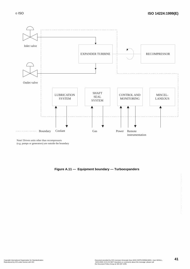
© ISO ISO 14224:1999(E)
41
Inlet valve
Outlet valve
EXPANDER TURBINE RECOMPRESSOR
LUBRICATIONSYSTEM
SHAFTSEAL
SYSTEM
CONTROL ANDMONITORING
MISCEL-LANEOUS
Boundary
Note! Driven units other than recompressors(e.g. pumps or generators) are outside the boundary
Coolant Gas Power Remoteinstrumentation
Figure A.11 — Equipment boundary — Turboexpanders
Copyright International Organization for Standardization Reproduced by IHS under license with ISO
Document provided by IHS Licensee=Amerada Hess WAN SSPPU/5958418001, User=MHALL, 04/21/2004 19:31:52 MDT Questions or comments about this message: please callthe Document Policy Group at 303-397-2295.
--````,``,,,`,,```,```,`,``,``,`,``````,,`,`,,,`````-`-`,,`,,`,`,,`---
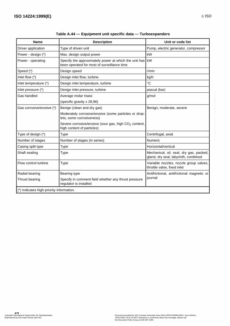
ISO 14224:1999(E) © ISO
42
Table A.44 — Equipment unit specific data — Turboexpanders
Name Description Unit or code list
Driver application Type of driven unit Pump, electric generator, compressor
Power - design (*) Max. design output power kW
Power - operating Specify the approximately power at which the unit hasbeen operated for most of surveillance time
kW
Speed (*) Design speed r/min
Inlet flow (*) Design inlet flow, turbine kg/h
Inlet temperature (*) Design inlet temperature, turbine °C
Inlet pressure (*) Design inlet pressure, turbine pascal (bar)
Gas handled Average molar mass
(specific gravity x 28,96)
g/mol
Gas corrosive/erosive (*) Benign (clean and dry gas)
Moderately corrosive/erosive (some particles or drop-lets, some corrosiveness)
Severe corrosive/erosive (sour gas, high CO2 content,high content of particles)
Benign, moderate, severe
Type of design (*) Type Centrifugal, axial
Number of stages Number of stages (in series) Numeric
Casing split type Type Horizontal/vertical
Shaft sealing Type Mechanical, oil, seal, dry gas, packed,gland, dry seal, labyrinth, combined
Flow control turbine Type Variable nozzles, nozzle group valves,throttle valve, fixed inlet
Radial bearing
Thrust bearing
Bearing type
Specify in comment field whether any thrust pressureregulator is installed
Antifrictional, antifrictional magnetic orjournal
(*) Indicates high-priority information.
Copyright International Organization for Standardization Reproduced by IHS under license with ISO
Document provided by IHS Licensee=Amerada Hess WAN SSPPU/5958418001, User=MHALL, 04/21/2004 19:31:52 MDT Questions or comments about this message: please callthe Document Policy Group at 303-397-2295.
--````,``,,,`,,```,```,`,``,``,`,``````,,`,`,,,`````-`-`,,`,,`,`,,`---
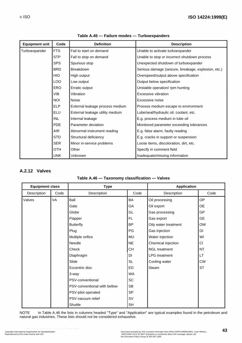
© ISO ISO 14224:1999(E)
43
Table A.45 — Failure modes — Turboexpanders
Equipment unit Code Definition Description
Turboexpander FTS Fail to start on demand Unable to activate turboexpander
STP Fail to stop on demand Unable to stop or incorrect shutdown process
SPS Spurious stop Unexpected shutdown of turboexpander
BRD Breakdown Serious damage (seizure, breakage, explosion, etc.)
HIO High output Overspeed/output above specification
LOO Low output Output below specification
ERO Erratic output Unstable operation/ rpm hunting
VIB Vibration Excessive vibration
NOI Noise Excessive noise
ELP External leakage process medium Process medium escape to environment
ELU External leakage utility medium Lube/seal/hydraulic oil, coolant, etc.
INL Internal leakage E.g. process medium in lube oil
PDE Parameter deviation Monitored parameter exceeding tolerances
AIR Abnormal instrument reading E.g. false alarm, faulty reading
STD Structural deficiency E.g. cracks in support or suspension
SER Minor in-service problems Loose items, discoloration, dirt, etc.
OTH Other Specify in comment field
UNK Unknown Inadequate/missing information
A.2.12 Valves
Table A.46 — Taxonomy classification — Valves
Equipment class Type Application
Description Code Description Code Description Code
Valves VA Ball BA Oil processing OP
Gate GA Oil export OE
Globe GL Gas processing GP
Flapper FL Gas export GE
Butterfly BP Oily water treatment OW
Plug PG Gas injection GI
Multiple orifice MU Water injection WI
Needle NE Chemical injection CI
Check CH NGL treatment NT
Diaphragm DI LPG treatment LT
Slide SL Cooling water CW
Eccentric disc ED Steam ST
3-way WA
PSV-conventional SC
PSV-conventional with bellow SB
PSV-pilot operated SP
PSV-vacuum relief SV
Shuttle SH
NOTE In Table A.46 the lists in columns headed "Type" and "Application" are typical examples found in the petroleum andnatural gas industries. These lists should not be considered exhaustive.
Copyright International Organization for Standardization Reproduced by IHS under license with ISO
Document provided by IHS Licensee=Amerada Hess WAN SSPPU/5958418001, User=MHALL, 04/21/2004 19:31:52 MDT Questions or comments about this message: please callthe Document Policy Group at 303-397-2295.
--````,``,,,`,,```,```,`,``,``,`,``````,,`,`,,,`````-`-`,,`,,`,`,,`---
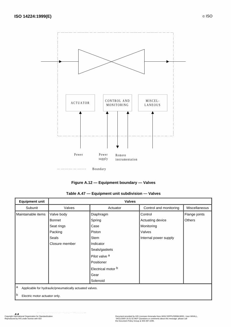
ISO 14224:1999(E) © ISO
44
Bounda ry
A C T U A T O RC O N T R O L A N DM O N I T O R I N G
M I S C E L -L A N E O U S
P o w e r P o w e rsupp ly
Remo teins t rumentat ion
Figure A.12 — Equipment boundary — Valves
Table A.47 — Equipment unit subdivision — Valves
Equipment unit Valves
Subunit Valves Actuator Control and monitoring Miscellaneous
Maintainable items Valve body
Bonnet
Seat rings
Packing
Seals
Closure member
Diaphragm
Spring
Case
Piston
Stem
Indicator
Seals/gaskets
Pilot valve a
Positioner
Electrical motor b
Gear
Solenoid
Control
Actuating device
Monitoring
Valves
Internal power supply
Flange joints
Others
a Applicable for hydraulic/pneumatically actuated valves.
b Electric motor actuator only.
Copyright International Organization for Standardization Reproduced by IHS under license with ISO
Document provided by IHS Licensee=Amerada Hess WAN SSPPU/5958418001, User=MHALL, 04/21/2004 19:31:52 MDT Questions or comments about this message: please callthe Document Policy Group at 303-397-2295.
--````,``,,,`,,```,```,`,``,``,`,``````,,`,`,,,`````-`-`,,`,,`,`,,`---
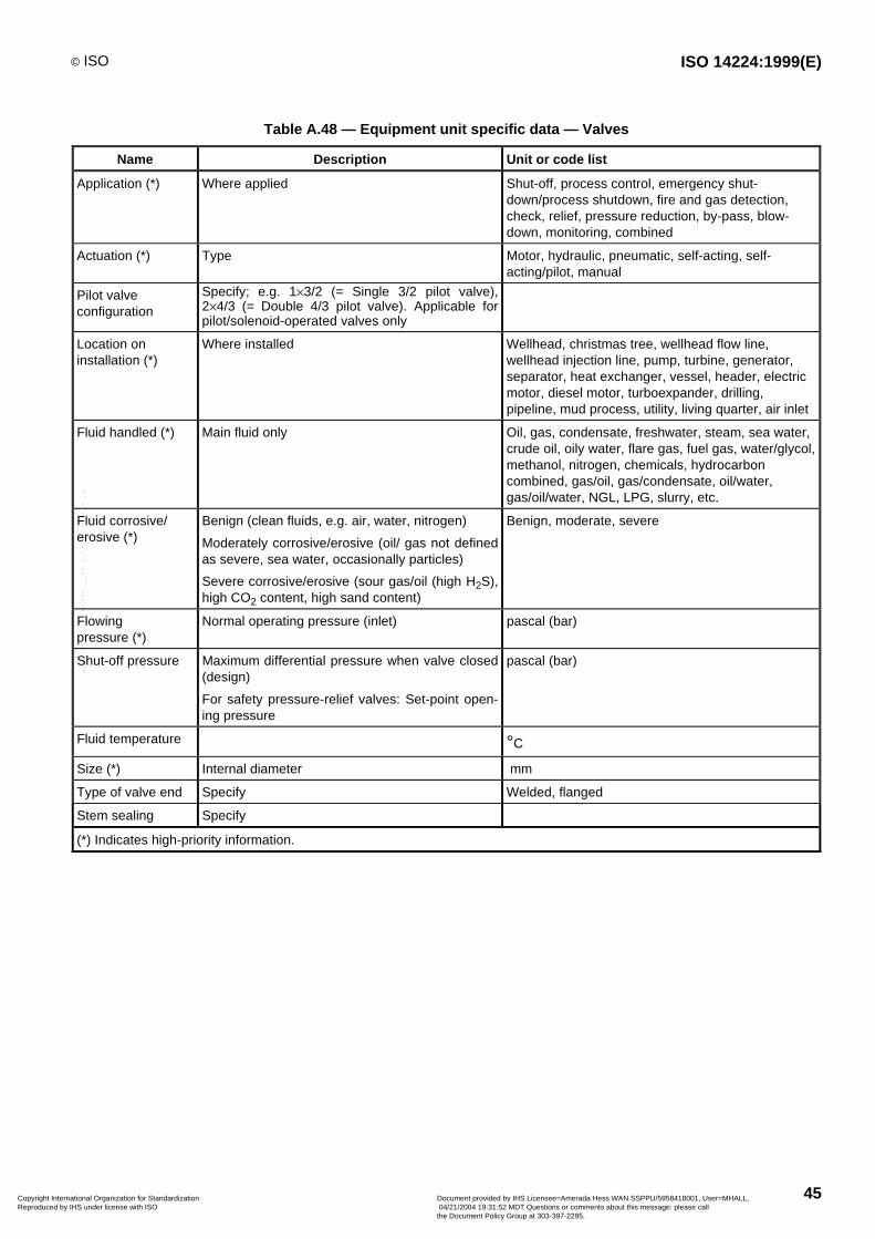
© ISO ISO 14224:1999(E)
45
Table A.48 — Equipment unit specific data — Valves
Name Description Unit or code list
Application (*) Where applied Shut-off, process control, emergency shut-down/process shutdown, fire and gas detection,check, relief, pressure reduction, by-pass, blow-down, monitoring, combined
Actuation (*) Type Motor, hydraulic, pneumatic, self-acting, self-acting/pilot, manual
Pilot valveconfiguration
Specify; e.g. 1¥3/2 (= Single 3/2 pilot valve),2¥4/3 (= Double 4/3 pilot valve). Applicable forpilot/solenoid-operated valves only
Location oninstallation (*)
Where installed Wellhead, christmas tree, wellhead flow line,wellhead injection line, pump, turbine, generator,separator, heat exchanger, vessel, header, electricmotor, diesel motor, turboexpander, drilling,pipeline, mud process, utility, living quarter, air inlet
Fluid handled (*) Main fluid only Oil, gas, condensate, freshwater, steam, sea water,crude oil, oily water, flare gas, fuel gas, water/glycol,methanol, nitrogen, chemicals, hydrocarboncombined, gas/oil, gas/condensate, oil/water,gas/oil/water, NGL, LPG, slurry, etc.
Fluid corrosive/erosive (*)
Benign (clean fluids, e.g. air, water, nitrogen)
Moderately corrosive/erosive (oil/ gas not definedas severe, sea water, occasionally particles)
Severe corrosive/erosive (sour gas/oil (high H2S),high CO2 content, high sand content)
Benign, moderate, severe
Flowingpressure (*)
Normal operating pressure (inlet) pascal (bar)
Shut-off pressure Maximum differential pressure when valve closed(design)
For safety pressure-relief valves: Set-point open-ing pressure
pascal (bar)
Fluid temperature °C
Size (*) Internal diameter mm
Type of valve end Specify Welded, flanged
Stem sealing Specify
(*) Indicates high-priority information.
Copyright International Organization for Standardization Reproduced by IHS under license with ISO
Document provided by IHS Licensee=Amerada Hess WAN SSPPU/5958418001, User=MHALL, 04/21/2004 19:31:52 MDT Questions or comments about this message: please callthe Document Policy Group at 303-397-2295.
--````,``,,,`,,```,```,`,``,``,`,``````,,`,`,,,`````-`-`,,`,,`,`,,`---

ISO 14224:1999(E) © ISO
46
Table A.49 — Failure modes — Valves
Equipment unit Code Definition Description
Valves FTC Fail to close on demand Stuck open or fail to close fully
FTO Fail to open on demand Stuck closed or fail to open fully
FTR Fail to regulate "Stuck" valve, control valves only
OWD Operates without demand Undesired closure/opening
DOP Delayed operation Opening/closure time different from specification
HIO High output Faulty regulation, control valves only
LOO Low output Faulty regulation, control valves only
ELP External leakage process medium Process medium escape to environment
ELU External leakage utility medium Actuation fluid, lubrication, etc.
INL Internal leakage Internal leakage of actuating fluid, or valve-actuatorcommunication
LCP Leakage in closed position Leak-through valve in closed position
PLU Plugged/Choked Partial or full flow restriction
STD Structural deficiency Reduced integrity due to impact, unacceptable
corrosion, cracks, etc.
AIR Abnormal instrument reading E.g. faulty position indication
SER Minor in-service problems Loose items, discoloration, dirt, etc.
OTH Other Specify in comment field
UNK Unknown Inadequate/missing information
A.2.13 Vessels
Table A.50 — Taxonomy classification — Vessels
Equipment class Type Application
Description Code Description Code Description Code
Vessel VE Stripper SP Oil processing OP
Separator SE Oily water treatment OW
Coalescer CA Gas processing GP
Flash drum FD Gas treatment GT
Scrubber SB Gas export GE
Contactor CO Flare, vent, blowdown FL
Surge drum SD NGL treatment NT
Hydrocyclone HY LPG treatment LT
Chemical storage CS
NOTE In Table A.50 the lists in columns headed "Type" and "Application" are typical examples found in the petroleum andnatural gas industries. These lists should not be considered exhaustive.
Copyright International Organization for Standardization Reproduced by IHS under license with ISO
Document provided by IHS Licensee=Amerada Hess WAN SSPPU/5958418001, User=MHALL, 04/21/2004 19:31:52 MDT Questions or comments about this message: please callthe Document Policy Group at 303-397-2295.
--````,``,,,`,,```,```,`,``,``,`,``````,,`,`,,,`````-`-`,,`,,`,`,,`---

© ISO ISO 14224:1999(E)
47
Out let valveInlet valve
Pressure rel iefvalve
C O N T R O L A N D M O N I T O R I N GS Y S T E M
Drain va lve
Power Remoteinst rumentat ion
Boundary
M I S C E L -L A N E O U S
E X T E R N A L I N T E R N A L
Figure A.13 — Equipment boundary — Vessels
Table A.51 — Equipment unit subdivision — Vessels
Equipment
unit
Vessels
Subunit External items Internal items Control and monitoring Miscellaneous
Maintainableitems
Support
Body/Shell
Valves
Piping
Body/Shell
Plates, trays, vanes, pads
Sand trap system
Heater
Corrosion protection
Distributor
Coil
Control
Actuating device
Monitoring
Valves
Internal power supply
Others
Copyright International Organization for Standardization Reproduced by IHS under license with ISO
Document provided by IHS Licensee=Amerada Hess WAN SSPPU/5958418001, User=MHALL, 04/21/2004 19:31:52 MDT Questions or comments about this message: please callthe Document Policy Group at 303-397-2295.
--````,``,,,`,,```,```,`,``,``,`,``````,,`,`,,,`````-`-`,,`,,`,`,,`---
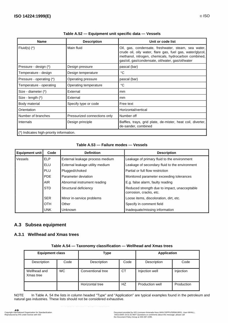
ISO 14224:1999(E) © ISO
48
Table A.52 — Equipment unit specific data — Vessels
Name Description Unit or code list
Fluid(s) (*) Main fluid Oil, gas, condensate, freshwater, steam, sea water,crude oil, oily water, flare gas, fuel gas, water/glycol,methanol, nitrogen, chemicals, hydrocarbon combined,gas/oil, gas/condensate, oil/water, gas/oil/water
Pressure - design (*) Design pressure pascal (bar)
Temperature - design Design temperature °C
Pressure - operating (*) Operating pressure pascal (bar)
Temperature - operating Operating temperature °C
Size - diameter (*) External mm
Size - length (*) External mm
Body material Specify type or code Free text
Orientation Horizontal/vertical
Number of branches Pressurized connections only Number off
Internals Design principle Baffles, trays, grid plate, de-mister, heat coil, diverter,de-sander, combined
(*) Indicates high-priority information.
Table A.53 — Failure modes — Vessels
Equipment unit Code Definition Description
Vessels ELP External leakage process medium Leakage of primary fluid to the environment
ELU External leakage utility medium Leakage of secondary fluid to the environment
PLU Plugged/choked Partial or full flow restriction
PDE Parameter deviation Monitored parameter exceeding tolerances
AIR Abnormal instrument reading E.g. false alarm, faulty reading
STD Structural deficiency Reduced strength due to impact, unacceptablecorrosion, cracks, etc.
SER Minor in-service problems Loose items, discoloration, dirt, etc.
OTH Other Specify in comment field
UNK Unknown Inadequate/missing information
A.3 Subsea equipment
A.3.1 Wellhead and Xmas trees
Table A.54 — Taxonomy classification — Wellhead and Xmas trees
Equipment class Type Application
Description Code Description Code Description Code
Wellhead andXmas tree
WC Conventional tree CT Injection well Injection
Horizontal tree HZ Production well Production
NOTE In Table A. 54 the lists in column headed "Type" and "Application" are typical examples found in the petroleum andnatural gas industries. These lists should not be considered exhaustive.
Copyright International Organization for Standardization Reproduced by IHS under license with ISO
Document provided by IHS Licensee=Amerada Hess WAN SSPPU/5958418001, User=MHALL, 04/21/2004 19:31:52 MDT Questions or comments about this message: please callthe Document Policy Group at 303-397-2295.
--````,``,,,`,,```,```,`,``,``,`,``````,,`,`,,,`````-`-`,,`,,`,`,,`---
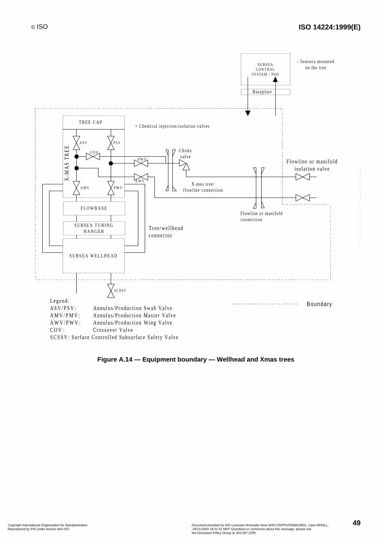
© ISO ISO 14224:1999(E)
49
T R E E C A P
A M V P M V
P W V
A W V
A S V P S V
X-M
AS
TR
EE
C O V
Tree /we l lheadconnec tor
Legend :A S V / P S V : Annu lus /Produc t ion Swab Va lveA M V / P M V : Annu lus /Produc t ion Mas te r Va lveA W V / P W V : Annu lus /Produc t ion Wing Va lveC O V : Crossover Va lveS C S S V : Sur face Cont ro l led Subsur face Safe ty Va lve
S C S S V
S U B S E AC O N T R O L
S Y S T E M / P O D
- Sensors mountedon the t ree
Basepla te
Flowl ine or mani fo ldconnec t ion
C h o k evalve
+ Chemical in ject ion/ iso lat ion valves
X-mas t ree/f lowl ine connect ion
F lowl ine or mani fo ldiso lat ion valve
Boundary
F L O W B A S E
S U B S E A T U B I N GH A N G E R
S U B S E A W E L L H E A D
Figure A.14 — Equipment boundary — Wellhead and Xmas trees
Copyright International Organization for Standardization Reproduced by IHS under license with ISO
Document provided by IHS Licensee=Amerada Hess WAN SSPPU/5958418001, User=MHALL, 04/21/2004 19:31:52 MDT Questions or comments about this message: please callthe Document Policy Group at 303-397-2295.
--````,``,,,`,,```,```,`,``,``,`,``````,,`,`,,,`````-`-`,,`,,`,`,,`---
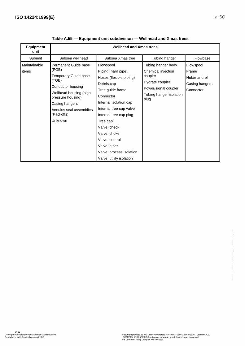
ISO 14224:1999(E) © ISO
50
Table A.55 — Equipment unit subdivision — Wellhead and Xmas trees
Equipmentunit
Wellhead and Xmas trees
Subunit Subsea wellhead Subsea Xmas tree Tubing hanger Flowbase
Maintainable
items
Permanent Guide base(PGB)
Temporary Guide base(TGB)
Conductor housing
Wellhead housing (highpressure housing)
Casing hangers
Annulus seal assemblies(Packoffs)
Unknown
Flowspool
Piping (hard pipe)
Hoses (flexible piping)
Debris cap
Tree guide frame
Connector
Internal isolation cap
Internal tree cap valve
Internal tree cap plug
Tree cap
Valve, check
Valve, choke
Valve, control
Valve, other
Valve, process isolation
Valve, utility isolation
Tubing hanger body
Chemical injectioncoupler
Hydrate coupler
Power/signal coupler
Tubing hanger isolationplug
Flowspool
Frame
Hub/mandrel
Casing hangers
Connector
Copyright International Organization for Standardization Reproduced by IHS under license with ISO
Document provided by IHS Licensee=Amerada Hess WAN SSPPU/5958418001, User=MHALL, 04/21/2004 19:31:52 MDT Questions or comments about this message: please callthe Document Policy Group at 303-397-2295.
--````,``,,,`,,```,```,`,``,``,`,``````,,`,`,,,`````-`-`,,`,,`,`,,`---
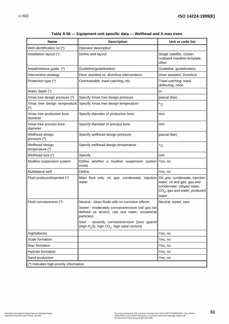
© ISO ISO 14224:1999(E)
51
Table A.56 — Equipment unit specific data — Wellhead and X-mas trees
Name Description Unit or code list
Well identification no.(*) Operator description
Installation layout (*) Define well layout Single satellite, cluster,multiwell manifold template,other
Install/retrieve guide (*) Guideline/guidelineless Guideline, guidelineless
Intervention strategy Diver assisted vs. diverless interventions Diver assisted, Diverless
Protection type (*) Overtrawable, trawl-catching, etc. Trawl-catching, trawl-deflecting, none
Water depth (*) m
Xmas tree design pressure (*) Specify Xmas tree design pressure pascal (bar)
Xmas tree design temperature(*)
Specify Xmas tree design temperature °C
Xmas tree production borediameter
Specify diameter of production bore mm
Xmas tree annulus borediameter
Specify diameter of annulus bore mm
Wellhead designpressure (*)
Specify wellhead design pressure pascal (bar)
Wellhead designtemperature (*)
Specify wellhead design temperature °C
Wellhead size (*) Specify mm
Mudline suspension system Define whether a mudline suspension systemexists
Yes, no
Multilateral well Define Yes, no
Fluid produced/injected (*) Main fluid only: oil, gas, condensate, injectionwater
Oil, gas, condensate, injectionwater, oil and gas, gas andcondensate, oil/gas/ water,CO2, gas and water, produced
water
Fluid corrosiveness (*) Neutral - clean fluids with no corrosive effects
Sweet - moderately corrosive/erosive (oil/ gas notdefined as severe, raw sea water, occasionalparticles)
Sour - severely corrosive/erosive [sour gas/oil(high H2S), high CO2, high sand content]
Neutral, sweet, sour
Asphaltenes Yes, no
Scale formation Yes, no
Wax formation Yes, no
Hydrate formation Yes, no
Sand production Yes, no
(*) Indicates high-priority information.
Copyright International Organization for Standardization Reproduced by IHS under license with ISO
Document provided by IHS Licensee=Amerada Hess WAN SSPPU/5958418001, User=MHALL, 04/21/2004 19:31:52 MDT Questions or comments about this message: please callthe Document Policy Group at 303-397-2295.
--````,``,,,`,,```,```,`,``,``,`,``````,,`,`,,,`````-`-`,,`,,`,`,,`---

ISO 14224:1999(E) © ISO
52
Table A.57 — Failure modes — Wellhead and X-mas trees
Equipmentunit
Code Definition Description
Wellhead and ELP External leakage process medium Process medium leak to sea
Xmas tree ELU External leakage utility medium Hydraulic fluid, methanol, etc.
ILP Internal leakage - Process medium E.g. annulus to production bore communication
ILU Internal leakage - Utility medium E.g. internal leakage of hydraulic fluid or chemicals
PLU Plugged/choked Partial or full flow restriction due to hydrate, scale,wax, etc.
STD Structural deficiency Reduced integrity due to impact, unacceptablecorrosion, cracks, etc.
OTH Other Specify in comment field
UNK Unknown Inadequate/missing information
NON No immediate effect
Failure modes should be specified on all three indenture levels of the equipment hierarchy, to enhance the usabilityof the data in later applications. The failure modes in Table A.57 are related to equipment level, i.e. wellhead andXmas tree.
A.4 Well-completion equipment
A.4.1 Equipment data
A.4.1.1 Item categories
Well-completion equipment in this context refers to equipment below wellhead level. All major completion equipmentitems are included, from tubing hanger at the top end to equipment at the bottom of the well.
The following item categories are defined for well-completion equipment:
a) String items
String items are defined as items which are all integral parts of the conduit ("string") used for production orinjection of well effluents. The string is built by screwing together a variety of equipment items.
b) Accessories
Accessories are items which must be tied to a "host" string item to define a system. This is done to be able tologically represent string items which are too complex to be given as just a stand-alone item of the string. Onlytwo such "host" string items, or string items with accessories, have been defined to date. These are ElectricalSubmersible Pump (ESP) and Downhole Permanent Gauge (DHPG) systems.
c) Inserted items
Inserted items are defined as items which can be attached (set) inside string items. A typical example is thecombination of a lock and wireline-retrievable safety valve set inside a safety valve nipple.
d) Control line/cable
The control line/cable category allows information to be stored for control lines and cables and a variety of partswhich are normally associated with control lines or cables. Examples of such parts are packer penetrators,electric connectors for gauges, electric wellhead connectors, etc. This category provides the opportunity tobuild control line/cable "systems" consisting of the hydraulic control line or cable itself and all associated parts.
Copyright International Organization for Standardization Reproduced by IHS under license with ISO
Document provided by IHS Licensee=Amerada Hess WAN SSPPU/5958418001, User=MHALL, 04/21/2004 19:31:52 MDT Questions or comments about this message: please callthe Document Policy Group at 303-397-2295.
--````,``,,,`,,```,```,`,``,``,`,``````,,`,`,,,`````-`-`,,`,,`,`,,`---

© ISO ISO 14224:1999(E)
53
Reliability analysis will then subsequently be possible for the control line system when the system has been tiedto a specific string item in a completion.
Each control line/cable shall always be connected to one or more string items.
e) Casing
The casing category is included to store information on individual casing string sections and associated casingfailures. The casing category represents full lengths of individual casing sections and does not representindividual items threaded into the casing string, compared with the production/injection string.
Sealing elements which are designed to seal off against leakage of hydrocarbons between the various sectionsof casing string (casing pack-offs) are not included.
A.4.1.2 Standard equipment specifications
Table A.58 — Item database format and name specification
Item category Data collection format Predefined item name
String item Annulus safety valve Tubing-retrievable surface-controlled annularsubsurface safety valve (TR-SCASSV)
Default Adjustable union
Landing nipple
Millout extension
Muleshoe
Nipple for wireline-SCSSV
Gravel pack screen
Perforated pup joint
Pup joint
Sliding sleeve
Tubing anchor
Wireline re-entry guide
Electrical submersible pumpsystem with accessories
Electrical submersible pump unit (straight)
Electrical submersible pump unit (y-tool)
Expansion joint Expansion joint
Flow coupling Flow coupling
Gauge mandrel with accessories Permanent gauge mandrel
Packer type Production packer
Downhole packer/hanger
Seal assembly Seal assembly (conventional)
Seal assembly (overshot )
Side pocket mandrel Side pocket mandrel (for valve )
Spacer type Spacer
Tubing type Tubing
Tubing safety valve Tubing-retrievable surface-controlled subsurface safetyvalve (TR-SCSSV)(ball)
Tubing-retrievable surface-controlled subsurface safetyvalve (TR-SCSSV)(flapper)
X-over X-over
Y-block Y-block
Copyright International Organization for Standardization Reproduced by IHS under license with ISO
Document provided by IHS Licensee=Amerada Hess WAN SSPPU/5958418001, User=MHALL, 04/21/2004 19:31:52 MDT Questions or comments about this message: please callthe Document Policy Group at 303-397-2295.
--````,``,,,`,,```,```,`,``,``,`,``````,,`,`,,,`````-`-`,,`,,`,`,,`---

ISO 14224:1999(E) © ISO
54
Table A.58 (end)
Item category Data collection format Predefined item name
Accessories Default None defined
Downhole gauge Permanent gauge
Intake section Intake section
Motor Electrical submersible pump motor
Motor lead extension Motor lead extension
Motor seal system Motor seal system
Pump Pump with electric drive
Inserted item Annulus safety valve Wireline surface-controlled subsurface safety valve(SCSSV)
Default Brain (sideguard)
Lock for wireline surface-controlled annular subsurfacesafety valve (SCASSV)
Gas lift valve Gas lift valve
Chemical injection valve
Safety valve Wireline-SCSSV
Control line/cable Default None defined
Electric connector, gauge Electric connector downhole gauge
Electric connector, hanger Electric connector tubing hanger
Hydraulic line Hydraulic control line
Penetrator Wellhead penetrator
Hanger penetrator
Packer penetrator
Power cable Power cable
Signal cable Signal/instrument cable
Surface controller Surface controller
Casing
An example of data collection format with associated data field definitions and registration alternatives is shown fora tubing item in Table A.59.
Copyright International Organization for Standardization Reproduced by IHS under license with ISO
Document provided by IHS Licensee=Amerada Hess WAN SSPPU/5958418001, User=MHALL, 04/21/2004 19:31:52 MDT Questions or comments about this message: please callthe Document Policy Group at 303-397-2295.
--````,``,,,`,,```,```,`,``,``,`,``````,,`,`,,,`````-`-`,,`,,`,`,,`---
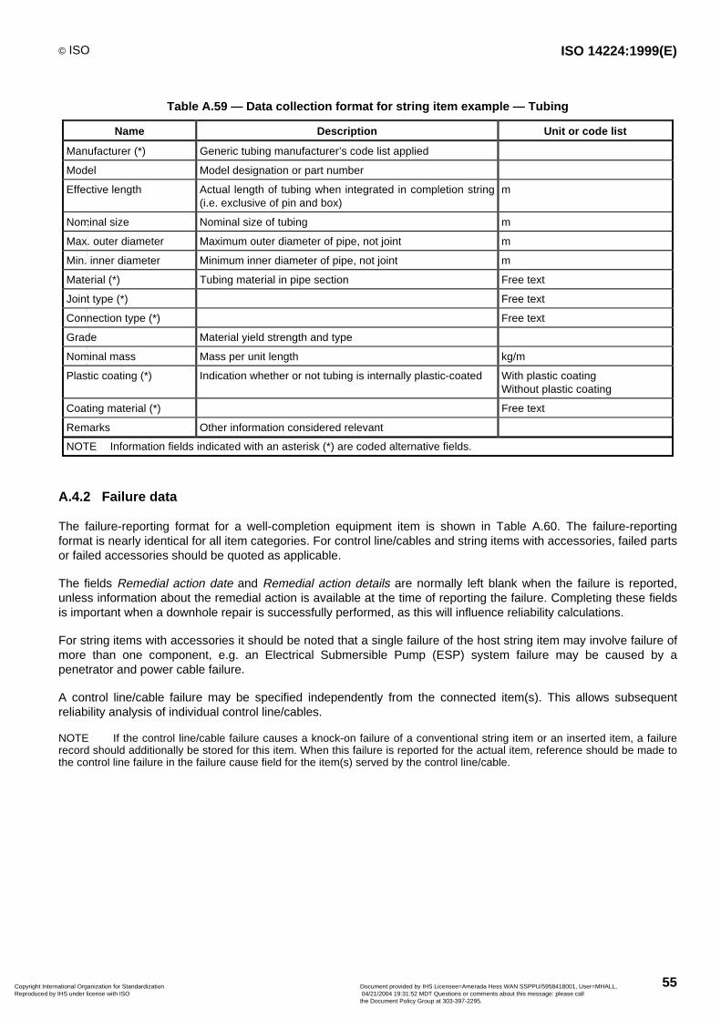
© ISO ISO 14224:1999(E)
55
Table A.59 — Data collection format for string item example — Tubing
Name Description Unit or code list
Manufacturer (*) Generic tubing manufacturer’s code list applied
Model Model designation or part number
Effective length Actual length of tubing when integrated in completion string(i.e. exclusive of pin and box)
m
Nominal size Nominal size of tubing m
Max. outer diameter Maximum outer diameter of pipe, not joint m
Min. inner diameter Minimum inner diameter of pipe, not joint m
Material (*) Tubing material in pipe section Free text
Joint type (*) Free text
Connection type (*) Free text
Grade Material yield strength and type
Nominal mass Mass per unit length kg/m
Plastic coating (*) Indication whether or not tubing is internally plastic-coated With plastic coatingWithout plastic coating
Coating material (*) Free text
Remarks Other information considered relevant
NOTE Information fields indicated with an asterisk (*) are coded alternative fields.
A.4.2 Failure data
The failure-reporting format for a well-completion equipment item is shown in Table A.60. The failure-reportingformat is nearly identical for all item categories. For control line/cables and string items with accessories, failed partsor failed accessories should be quoted as applicable.
The fields Remedial action date and Remedial action details are normally left blank when the failure is reported,unless information about the remedial action is available at the time of reporting the failure. Completing these fieldsis important when a downhole repair is successfully performed, as this will influence reliability calculations.
For string items with accessories it should be noted that a single failure of the host string item may involve failure ofmore than one component, e.g. an Electrical Submersible Pump (ESP) system failure may be caused by apenetrator and power cable failure.
A control line/cable failure may be specified independently from the connected item(s). This allows subsequentreliability analysis of individual control line/cables.
NOTE If the control line/cable failure causes a knock-on failure of a conventional string item or an inserted item, a failurerecord should additionally be stored for this item. When this failure is reported for the actual item, reference should be made tothe control line failure in the failure cause field for the item(s) served by the control line/cable.
Copyright International Organization for Standardization Reproduced by IHS under license with ISO
Document provided by IHS Licensee=Amerada Hess WAN SSPPU/5958418001, User=MHALL, 04/21/2004 19:31:52 MDT Questions or comments about this message: please callthe Document Policy Group at 303-397-2295.
--````,``,,,`,,```,```,`,``,``,`,``````,,`,`,,,`````-`-`,,`,,`,`,,`---
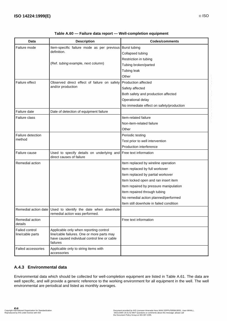
ISO 14224:1999(E) © ISO
56
Table A.60 — Failure data report — Well-completion equipment
Data Description Codes/comments
Failure mode Item-specific failure mode as per previousdefinition.
(Ref. tubing example, next column)
Burst tubing
Collapsed tubing
Restriction in tubing
Tubing broken/parted
Tubing leak
Other
Failure effect Observed direct effect of failure on safetyand/or production
Production affected
Safety affected
Both safety and production affected
Operational delay
No immediate effect on safety/production
Failure date Date of detection of equipment failure
Failure class Item-related failure
Non-item-related failure
Other
Failure detectionmethod
Periodic testing
Test prior to well intervention
Production interference
Failure cause Used to specify details on underlying anddirect causes of failure
Free text information
Remedial action Item replaced by wireline operation
Item replaced by full workover
Item replaced by partial workover
Item locked open and ran insert item
Item repaired by pressure manipulation
Item repaired through tubing
No remedial action planned/performed
Item still downhole in failed condition
Remedial action date Used to identify the date when downholeremedial action was performed.
Remedial actiondetails
Free text information
Failed controlline/cable parts
Applicable only when reporting controlline/cable failures. One or more parts mayhave caused individual control line or cablefailures
Failed accessories Applicable only to string items withaccessories
A.4.3 Environmental data
Environmental data which should be collected for well-completion equipment are listed in Table A.61. The data arewell specific, and will provide a generic reference to the working environment for all equipment in the well. The wellenvironmental are periodical and listed as monthly averages.
Copyright International Organization for Standardization Reproduced by IHS under license with ISO
Document provided by IHS Licensee=Amerada Hess WAN SSPPU/5958418001, User=MHALL, 04/21/2004 19:31:52 MDT Questions or comments about this message: please callthe Document Policy Group at 303-397-2295.
--````,``,,,`,,```,```,`,``,``,`,``````,,`,`,,,`````-`-`,,`,,`,`,,`---
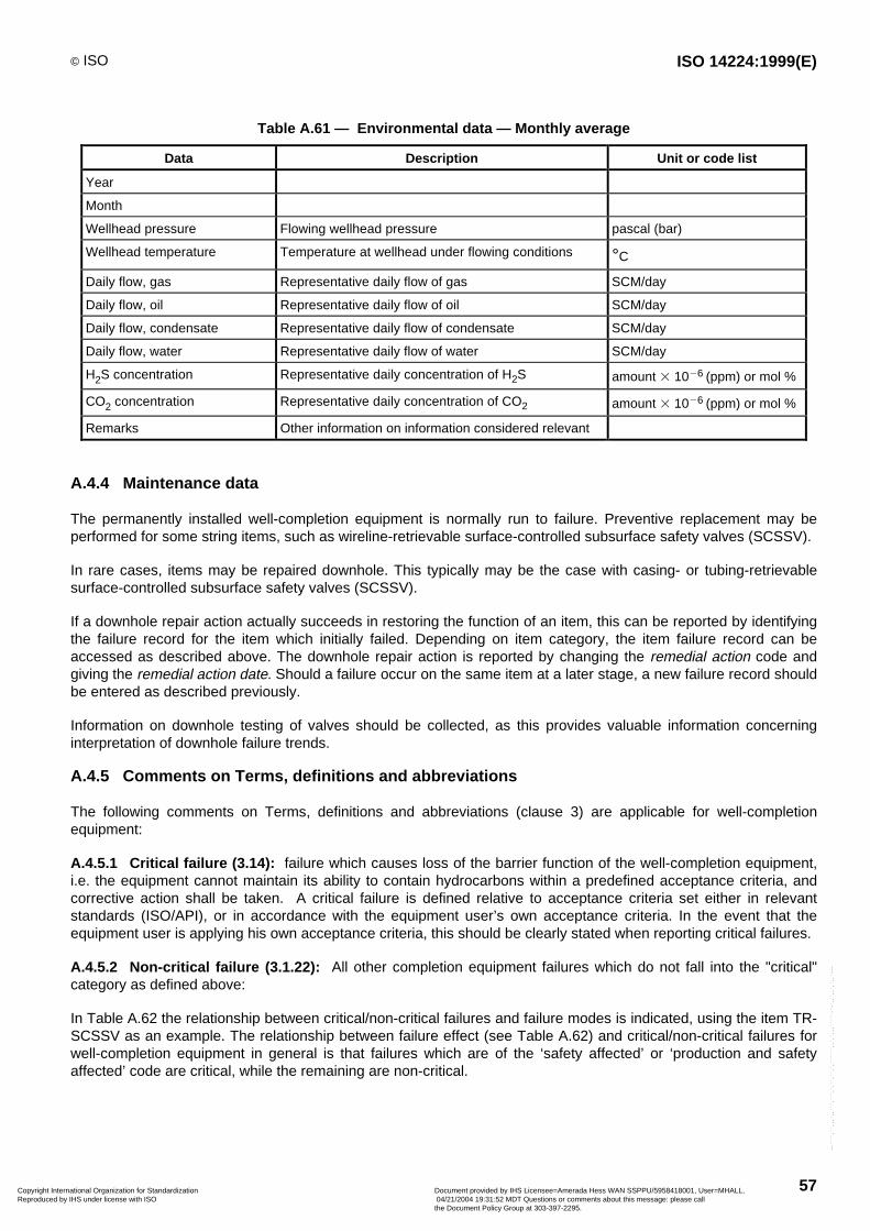
© ISO ISO 14224:1999(E)
57
Table A.61 — Environmental data — Monthly average
Data Description Unit or code list
Year
Month
Wellhead pressure Flowing wellhead pressure pascal (bar)
Wellhead temperature Temperature at wellhead under flowing conditions °C
Daily flow, gas Representative daily flow of gas SCM/day
Daily flow, oil Representative daily flow of oil SCM/day
Daily flow, condensate Representative daily flow of condensate SCM/day
Daily flow, water Representative daily flow of water SCM/day
H2S concentration Representative daily concentration of H2S amount 3 1026 (ppm) or mol %
CO2 concentration Representative daily concentration of CO2 amount 3 1026 (ppm) or mol %
Remarks Other information on information considered relevant
A.4.4 Maintenance data
The permanently installed well-completion equipment is normally run to failure. Preventive replacement may beperformed for some string items, such as wireline-retrievable surface-controlled subsurface safety valves (SCSSV).
In rare cases, items may be repaired downhole. This typically may be the case with casing- or tubing-retrievablesurface-controlled subsurface safety valves (SCSSV).
If a downhole repair action actually succeeds in restoring the function of an item, this can be reported by identifyingthe failure record for the item which initially failed. Depending on item category, the item failure record can beaccessed as described above. The downhole repair action is reported by changing the remedial action code andgiving the remedial action date. Should a failure occur on the same item at a later stage, a new failure record shouldbe entered as described previously.
Information on downhole testing of valves should be collected, as this provides valuable information concerninginterpretation of downhole failure trends.
A.4.5 Comments on Terms, definitions and abbreviations
The following comments on Terms, definitions and abbreviations (clause 3) are applicable for well-completionequipment:
A.4.5.1 Critical failure (3.14): failure which causes loss of the barrier function of the well-completion equipment,i.e. the equipment cannot maintain its ability to contain hydrocarbons within a predefined acceptance criteria, andcorrective action shall be taken. A critical failure is defined relative to acceptance criteria set either in relevantstandards (ISO/API), or in accordance with the equipment user’s own acceptance criteria. In the event that theequipment user is applying his own acceptance criteria, this should be clearly stated when reporting critical failures.
A.4.5.2 Non-critical failure (3.1.22): All other completion equipment failures which do not fall into the "critical"category as defined above:
In Table A.62 the relationship between critical/non-critical failures and failure modes is indicated, using the item TR-SCSSV as an example. The relationship between failure effect (see Table A.62) and critical/non-critical failures forwell-completion equipment in general is that failures which are of the ‘safety affected’ or ‘production and safetyaffected’ code are critical, while the remaining are non-critical.
Copyright International Organization for Standardization Reproduced by IHS under license with ISO
Document provided by IHS Licensee=Amerada Hess WAN SSPPU/5958418001, User=MHALL, 04/21/2004 19:31:52 MDT Questions or comments about this message: please callthe Document Policy Group at 303-397-2295.
--````,``,,,`,,```,```,`,``,``,`,``````,,`,`,,,`````-`-`,,`,,`,`,,`---
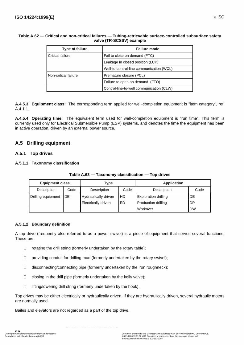
ISO 14224:1999(E) © ISO
58
Table A.62 — Critical and non-critical failures — Tubing-retrievable surface-controlled subsurface safetyvalve (TR-SCSSV) example
Type of failure Failure mode
Critical failure Fail to close on demand (FTC)
Leakage in closed position (LCP)
Well-to-control-line communication (WCL)
Non-critical failure Premature closure (PCL)
Failure to open on demand (FTO)
Control-line-to-well communication (CLW)
A.4.5.3 Equipment class: The corresponding term applied for well-completion equipment is "item category", ref.A.4.1.1.
A.4.5.4 Operating time : The equivalent term used for well-completion equipment is "run time". This term iscurrently used only for Electrical Submersible Pump (ESP) systems, and denotes the time the equipment has beenin active operation, driven by an external power source.
A.5 Drilling equipment
A.5.1 Top drives
A.5.1.1 Taxonomy classification
Table A.63 — Taxonomy classification — Top drives
Equipment class Type Application
Description Code Description Code Description Code
Drilling equipment DE Hydraulically driven HD Exploration drilling DE
Electrically driven ED Production drilling DP
Workover DW
A.5.1.2 Boundary definition
A top drive (frequently also referred to as a power swivel) is a piece of equipment that serves several functions.These are:
rotating the drill string (formerly undertaken by the rotary table);
providing conduit for drilling mud (formerly undertaken by the rotary swivel);
disconnecting/connecting pipe (formerly undertaken by the iron roughneck);
closing in the drill pipe (formerly undertaken by the kelly valve);
lifting/lowering drill string (formerly undertaken by the hook).
Top drives may be either electrically or hydraulically driven. If they are hydraulically driven, several hydraulic motorsare normally used.
Bailes and elevators are not regarded as a part of the top drive.
Copyright International Organization for Standardization Reproduced by IHS under license with ISO
Document provided by IHS Licensee=Amerada Hess WAN SSPPU/5958418001, User=MHALL, 04/21/2004 19:31:52 MDT Questions or comments about this message: please callthe Document Policy Group at 303-397-2295.
--````,``,,,`,,```,```,`,``,``,`,``````,,`,`,,,`````-`-`,,`,,`,`,,`---
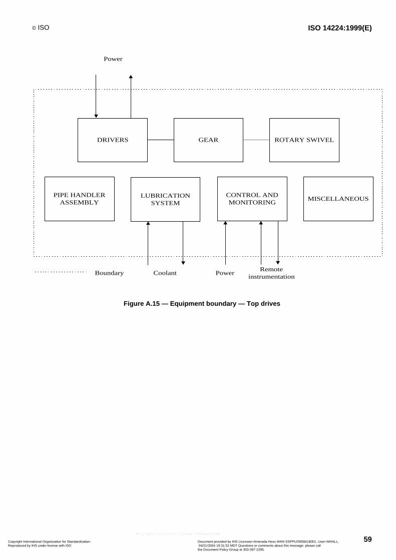
© ISO ISO 14224:1999(E)
59
DRIVERS GEAR ROTARY SWIVEL
PIPE HANDLERASSEMBLY
LUBRICATIONSYSTEM
CONTROL ANDMONITORING
MISCELLANEOUS
Boundary Coolant PowerRemote
instrumentation
Power
Figure A.15 — Equipment boundary — Top drives
Copyright International Organization for Standardization Reproduced by IHS under license with ISO
Document provided by IHS Licensee=Amerada Hess WAN SSPPU/5958418001, User=MHALL, 04/21/2004 19:31:52 MDT Questions or comments about this message: please callthe Document Policy Group at 303-397-2295.
--````,``,,,`,,```,```,`,``,``,`,``````,,`,`,,,`````-`-`,,`,,`,`,,`---

ISO 14224:1999(E) © ISO
60
A.5.1.3 Equipment unit subdivision
Top drives are subdivided in subunits and maintainable items as in Table A.64.
Table A.64 — Equipment unit subdivision — Top drives
Equipment
unit
Top drive/power swivel
Subunit Drivers Gear Rotary swivel Pipe-handlerassembly
Lubri-cation
Control andmonitoring
Miscellaneous
Maintainableitems
Electricdriver:
Stator
Rotor
Overloadprotection
Hydraulicdriver:
External seals
Gear
Angle piston
Piping/ hoses
General :
Coupling
Radial, thrustand axialbearing
Bearings
Gear lubricationpump
Packing/seals
Coupling todriver
Coupling toswivel
Pinion
Gooseneck
Packing/seals
Axial, radial andthrust bearing
Swivel housing
Swivel stem
Link hangerincl. tiltactuators
Pipe-handlerposition motor
Swivelcoupling
Torque wrench
Oil tankHeaters
Coolers
Pump withmotor
Valves
Filters
Lube oil
Control panel
Control
Electric and/orhydraulicsolenoidcabinet
Service loops
Manifolds
Junction box
Dolly frame
Internal blow-out preventer
Counter-balancecompensator
Copyright International Organization for Standardization Reproduced by IHS under license with ISO
Document provided by IHS Licensee=Amerada Hess WAN SSPPU/5958418001, User=MHALL, 04/21/2004 19:31:52 MDT Questions or comments about this message: please callthe Document Policy Group at 303-397-2295.
--````,``,,,`,,```,```,`,``,``,`,``````,,`,`,,,`````-`-`,,`,,`,`,,`---
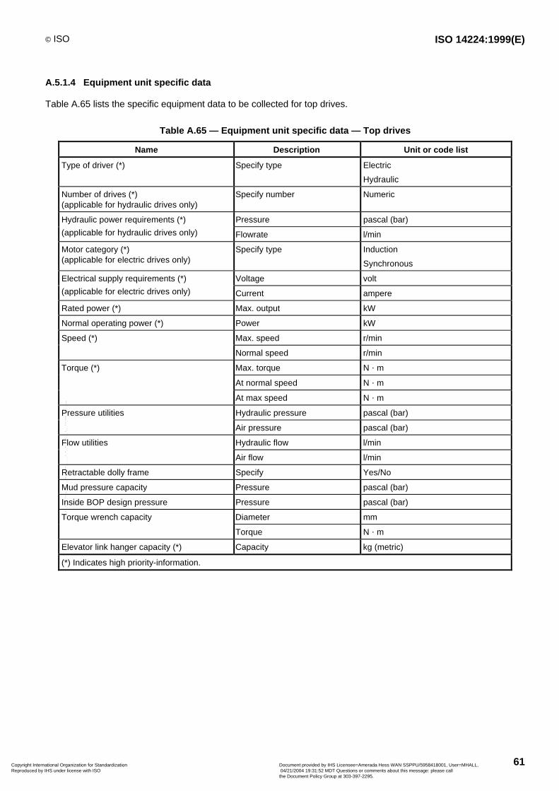
© ISO ISO 14224:1999(E)
61
A.5.1.4 Equipment unit specific data
Table A.65 lists the specific equipment data to be collected for top drives.
Table A.65 — Equipment unit specific data — Top drives
Name Description Unit or code list
Type of driver (*) Specify type Electric
Hydraulic
Number of drives (*)(applicable for hydraulic drives only)
Specify number Numeric
Hydraulic power requirements (*) Pressure pascal (bar)
(applicable for hydraulic drives only) Flowrate l/min
Motor category (*)(applicable for electric drives only)
Specify type Induction
Synchronous
Electrical supply requirements (*) Voltage volt
(applicable for electric drives only) Current ampere
Rated power (*) Max. output kW
Normal operating power (*) Power kW
Speed (*) Max. speed r/min
Normal speed r/min
Torque (*) Max. torque N • m
At normal speed N • m
At max speed N • m
Pressure utilities Hydraulic pressure pascal (bar)
Air pressure pascal (bar)
Flow utilities Hydraulic flow l/min
Air flow l/min
Retractable dolly frame Specify Yes/No
Mud pressure capacity Pressure pascal (bar)
Inside BOP design pressure Pressure pascal (bar)
Torque wrench capacity Diameter mm
Torque N • m
Elevator link hanger capacity (*) Capacity kg (metric)
(*) Indicates high priority-information.
Copyright International Organization for Standardization Reproduced by IHS under license with ISO
Document provided by IHS Licensee=Amerada Hess WAN SSPPU/5958418001, User=MHALL, 04/21/2004 19:31:52 MDT Questions or comments about this message: please callthe Document Policy Group at 303-397-2295.
--````,``,,,`,,```,```,`,``,``,`,``````,,`,`,,,`````-`-`,,`,,`,`,,`---
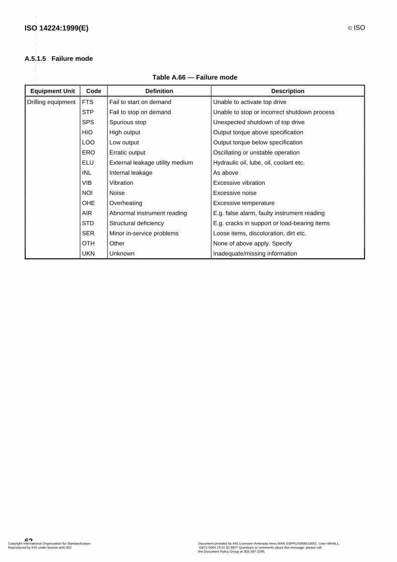
ISO 14224:1999(E) © ISO
62
A.5.1.5 Failure mode
Table A.66 — Failure mode
Equipment Unit Code Definition Description
Drilling equipment FTS Fail to start on demand Unable to activate top drive
STP Fail to stop on demand Unable to stop or incorrect shutdown process
SPS Spurious stop Unexpected shutdown of top drive
HIO High output Output torque above specification
LOO Low output Output torque below specification
ERO Erratic output Oscillating or unstable operation
ELU External leakage utility medium Hydraulic oil, lube, oil, coolant etc.
INL Internal leakage As above
VIB Vibration Excessive vibration
NOI Noise Excessive noise
OHE Overheating Excessive temperature
AIR Abnormal instrument reading E.g. false alarm, faulty instrument reading
STD Structural deficiency E.g. cracks in support or load-bearing items
SER Minor in-service problems Loose items, discoloration, dirt etc.
OTH Other None of above apply. Specify
UKN Unknown Inadequate/missing information
Copyright International Organization for Standardization Reproduced by IHS under license with ISO
Document provided by IHS Licensee=Amerada Hess WAN SSPPU/5958418001, User=MHALL, 04/21/2004 19:31:52 MDT Questions or comments about this message: please callthe Document Policy Group at 303-397-2295.
--````,``,,,`,,```,```,`,``,``,`,``````,,`,`,,,`````-`-`,,`,,`,`,,`---

© ISO ISO 14224:1999(E)
63
Annex B(informative)
Failure and maintenance notations
Table B.1 — Failure descriptors
No. Notation Description
1.0 Mechanical failure - general A failure related to some mechanical defect, but where no further details areknown
1.1 Leakage External and internal leakages, either liquids or gases. If the failure mode atequipment unit level is leakage, a more causal-oriented failure descriptor shouldbe used wherever possible
1.2 Vibration Abnormal vibration. If the failure mode at equipment level is vibration, a morecausal-oriented failure descriptor should be used wherever possible
1.3 Clearance/alignment failure Failure caused by faulty clearance or alignment
1.4 Deformation Distortion, bending, buckling, denting, yielding, shrinking, etc.
1.5 Looseness Disconnection, loose items
1.6 Sticking Sticking, seizure, jamming due to reasons other than deformation or clear-ance/alignment failures
2.0 Material failure - general A failure related to a material defect, but no further details known
2.1 Cavitation Relevant for equipment such as pumps and valves
2.2 Corrosion All types of corrosion, both wet (electrochemical) and dry (chemical)
2.3 Erosion Erosive wear
2.4 Wear Abrasive and adhesive wear, e.g. scoring, galling, scuffing, fretting, etc.
2.5 Breakage Fracture, breach, crack
2.6 Fatigue If the cause of breakage can be traced to fatigue, this code should be used
2.7 Overheating Material damage due to overheating/burning
2.8 Burst Item burst, blown, exploded, imploded, etc.
3.0 Instrument failure - general Failure related to instrumentation, but no details known
3.1 Control failure
3.2 No signal/indication/alarm No signal/indication/alarm when expected
3.3 Faulty signal/indication/alarm Signal/indication/alarm is wrong in relation to actual process. Could be spurious,intermittent, oscillating, arbitrary
3.4 Out of adjustment Calibration error, parameter drift
3.5 Software failure Faulty or no control/monitoring/operation due to software failure
3.6 Common mode failure Several instrument items failed simultaneously, e.g. redundant fire and gasdetectors
4.0 Electrical failure - general Failures related to the supply and transmission of electrical power, but where nofurther details are known
4.1 Short circuiting Short circuit
4.2 Open circuit Disconnection, interruption, broken wire/cable
4.3 No power/voltage Missing or insufficient electrical power supply
4.4 Faulty power/voltage Faulty electrical power supply, e.g. overvoltage
4.5 Earth/isolation fault Earth fault, low electrical resistance
Copyright International Organization for Standardization Reproduced by IHS under license with ISO
Document provided by IHS Licensee=Amerada Hess WAN SSPPU/5958418001, User=MHALL, 04/21/2004 19:31:52 MDT Questions or comments about this message: please callthe Document Policy Group at 303-397-2295.
--````,``,,,`,,```,```,`,``,``,`,``````,,`,`,,,`````-`-`,,`,,`,`,,`---
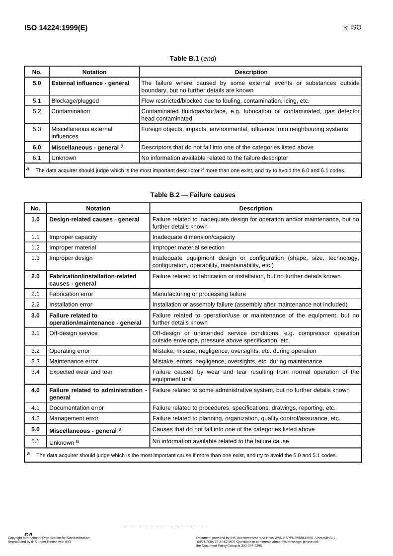
ISO 14224:1999(E) © ISO
64
Table B.1 (end)
No. Notation Description
5.0 External influence - general The failure where caused by some external events or substances outsideboundary, but no further details are known
5.1 Blockage/plugged Flow restricted/blocked due to fouling, contamination, icing, etc.
5.2 Contamination Contaminated fluid/gas/surface, e.g. lubrication oil contaminated, gas detectorhead contaminated
5.3 Miscellaneous externalinfluences
Foreign objects, impacts, environmental, influence from neighbouring systems
6.0 Miscellaneous - general a Descriptors that do not fall into one of the categories listed above
6.1 Unknown No information available related to the failure descriptor
a The data acquirer should judge which is the most important descriptor if more than one exist, and try to avoid the 6.0 and 6.1 codes.
Table B.2 — Failure causes
No. Notation Description
1.0 Design-related causes - general Failure related to inadequate design for operation and/or maintenance, but nofurther details known
1.1 Improper capacity Inadequate dimension/capacity
1.2 Improper material Improper material selection
1.3 Improper design Inadequate equipment design or configuration (shape, size, technology,configuration, operability, maintainability, etc.)
2.0 Fabrication/installation-relatedcauses - general
Failure related to fabrication or installation, but no further details known
2.1 Fabrication error Manufacturing or processing failure
2.2 Installation error Installation or assembly failure (assembly after maintenance not included)
3.0 Failure related tooperation/maintenance - general
Failure related to operation/use or maintenance of the equipment, but nofurther details known
3.1 Off-design service Off-design or unintended service conditions, e.g. compressor operationoutside envelope, pressure above specification, etc.
3.2 Operating error Mistake, misuse, negligence, oversights, etc. during operation
3.3 Maintenance error Mistake, errors, negligence, oversights, etc. during maintenance
3.4 Expected wear and tear Failure caused by wear and tear resulting from normal operation of theequipment unit
4.0 Failure related to administration -general
Failure related to some administrative system, but no further details known
4.1 Documentation error Failure related to procedures, specifications, drawings, reporting, etc.
4.2 Management error Failure related to planning, organization, quality control/assurance, etc.
5.0 Miscellaneous - general a Causes that do not fall into one of the categories listed above
5.1 Unknown a No information available related to the failure cause
a The data acquirer should judge which is the most important cause if more than one exist, and try to avoid the 5.0 and 5.1 codes.
Copyright International Organization for Standardization Reproduced by IHS under license with ISO
Document provided by IHS Licensee=Amerada Hess WAN SSPPU/5958418001, User=MHALL, 04/21/2004 19:31:52 MDT Questions or comments about this message: please callthe Document Policy Group at 303-397-2295.
--````,``,,,`,,```,```,`,``,``,`,``````,,`,`,,,`````-`-`,,`,,`,`,,`---
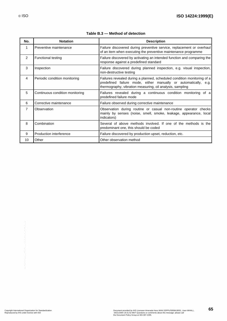
© ISO ISO 14224:1999(E)
65
Table B.3 — Method of detection
No. Notation Description
1 Preventive maintenance Failure discovered during preventive service, replacement or overhaulof an item when executing the preventive maintenance programme
2 Functional testing Failure discovered by activating an intended function and comparing theresponse against a predefined standard
3 Inspection Failure discovered during planned inspection, e.g. visual inspection,non-destructive testing
4 Periodic condition monitoring Failures revealed during a planned, scheduled condition monitoring of apredefined failure mode, either manually or automatically, e.g.thermography, vibration measuring, oil analysis, sampling
5 Continuous condition monitoring Failures revealed during a continuous condition monitoring of apredefined failure mode
6 Corrective maintenance Failure observed during corrective maintenance
7 Observation Observation during routine or casual non-routine operator checksmainly by senses (noise, smell, smoke, leakage, appearance, localindicators)
8 Combination Several of above methods involved. If one of the methods is thepredominant one, this should be coded
9 Production interference Failure discovered by production upset, reduction, etc.
10 Other Other observation method
Copyright International Organization for Standardization Reproduced by IHS under license with ISO
Document provided by IHS Licensee=Amerada Hess WAN SSPPU/5958418001, User=MHALL, 04/21/2004 19:31:52 MDT Questions or comments about this message: please callthe Document Policy Group at 303-397-2295.
--````,``,,,`,,```,```,`,``,``,`,``````,,`,`,,,`````-`-`,,`,,`,`,,`---

ISO 14224:1999(E) © ISO
66
Table B.4 — Maintenance activity
No. Activity Description Examples Usea
1 Replace Replacement of the item by a new, or refurbished,of the same type and make
Replacement of a worn-out bearing C, P
2 Repair Manual maintenance action performed to restorean item to its original appearance or state
Repack, weld, plug, reconnect,remake, etc.
C
3 Modify Replace, renew, or change the item, or a part of it,with an item/part of different type, make, materialor design
Install a filter with smaller meshdiameter, replace a lubrication oilpump with another type, etc.
C
4 Adjust Bringing any out-of-tolerance condition into toler-ance
Align, set and reset, calibrate,balance
C
5 Refit Minor repair/servicing activity to bring back anitem to an acceptable appearance, internal andexternal
Polish, clean, grind, paint, coat, lube,oil change, etc.
C
6 Check b The cause of the failure is investigated, but nomaintenance action performed, or action deferred.Able to regain function by simple actions, e.g.restart or resetting
Restart, resetting, etc. In particularrelevant for functional failures, e.g.fire and gas detectors
C
7 Service Periodic service tasks. Normally no dismantling ofthe item
E.g. cleaning, replenishment ofconsumables, adjustments andcalibrations
P
8 Test Periodic test of function availability Function test of fire pump, gasdetector etc.
P
9 Inspection Periodic inspection/check. A careful scrutiny of anitem carried out with or without dismantling, nor-mally by use of senses
All types of general checks. Includesminor servicing as part of theinspection task
P
10 Overhaul Major overhaul Comprehensive inspection/overhaulwith extensive disassembly andreplacement of items as specified orrequired
P(C)
11 Combination Several of the above activities are included If one activity is the dominating, thiscould alternatively be recorded
C, P
12 Other Maintenance activity other than specified above C, P
a C = used typically in corrective maintenance, P = used typically in preventive maintenance.
b "Check" includes both circumstances where a failure cause was revealed, but no maintenance action considered necessary, and whereno failure cause could be found.
Copyright International Organization for Standardization Reproduced by IHS under license with ISO
Document provided by IHS Licensee=Amerada Hess WAN SSPPU/5958418001, User=MHALL, 04/21/2004 19:31:52 MDT Questions or comments about this message: please callthe Document Policy Group at 303-397-2295.
--````,``,,,`,,```,```,`,``,``,`,``````,,`,`,,,`````-`-`,,`,,`,`,,`---
© ISO ISO 14224:1999(E)
67
Annex C(informative)
Quality control checklist
C.1 Quality control before and during data collection
A quality check procedure should be performed by the data acquirer for each new installation on which data arecollected and documented in proper format. The self-check should be an ongoing activity during the planning andexecution of the data collection process, and can typically be divided into two main phases:
a) before the data collection starts, viz.:
are data collection plans prepared and approved?
are relevant specifications of data to be collected in place, and procedures for quality control of dataavailable to and understood by personnel involved?
are required resources available (trained personnel, software, data sources, etc.)?
b) during data collection and finalization:
are data of sufficient quality and consistency, e.g.:
are definitions of boundaries and failure events adhered to?
are data correctly coded and commented for later analysis?
are data collected only for the time periods and equipment units specified?
are the following procedures followed:
reporting of deviations and interpretation problems?
a requirement on confidentiality, security and storing/shipment of data?
C.2 Verification of collected data
Typical checks to verify the quality of collected data would be:
frequency analyses to detect missing information, incorrect interpretation, proper coding, data consistency,irregular distributions;
spot checks on data as indicated in C.1 b).
The results of these checks should be documented and errors corrected. An example quality control form is given inTable C.1.
Copyright International Organization for Standardization Reproduced by IHS under license with ISO
Document provided by IHS Licensee=Amerada Hess WAN SSPPU/5958418001, User=MHALL, 04/21/2004 19:31:52 MDT Questions or comments about this message: please callthe Document Policy Group at 303-397-2295.
--````,``,,,`,,```,```,`,``,``,`,``````,,`,`,,,`````-`-`,,`,,`,`,,`---
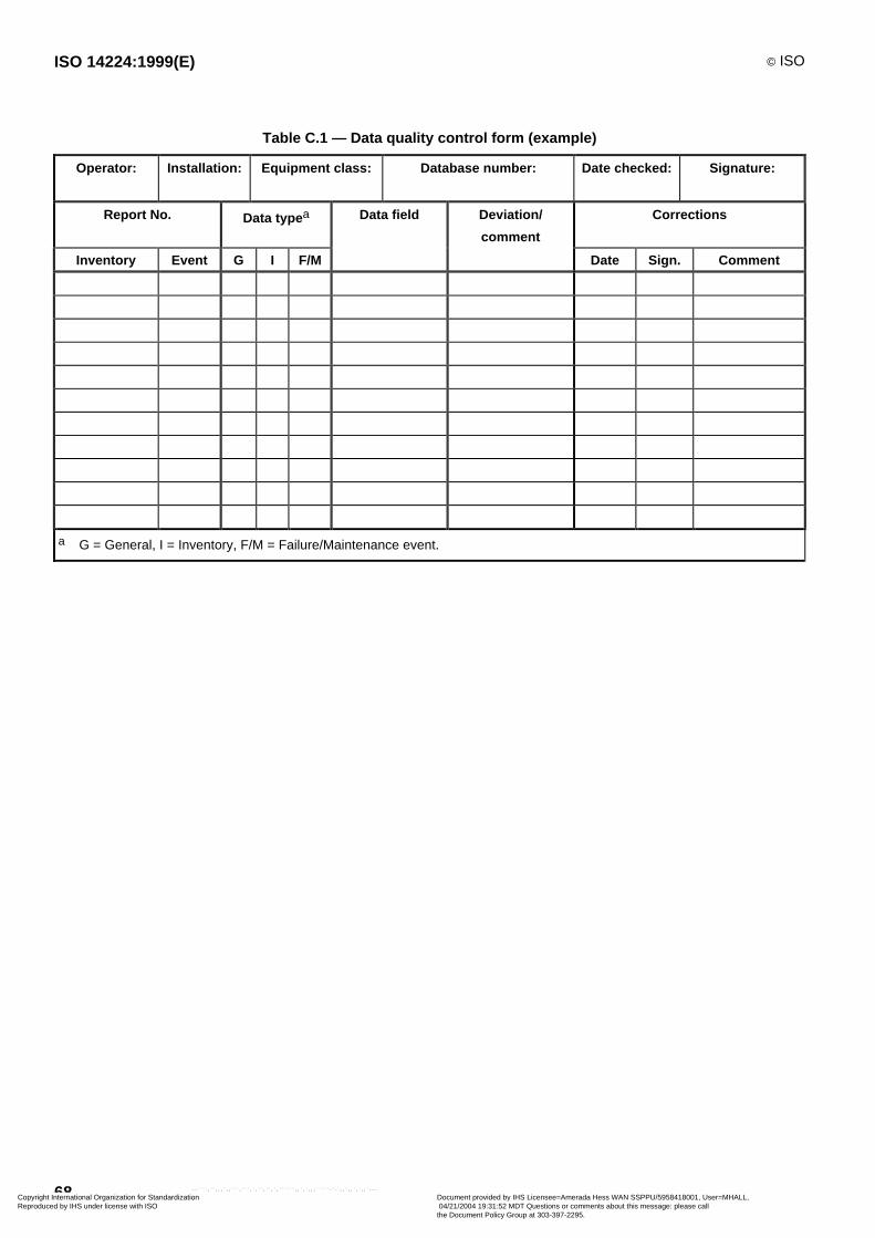
ISO 14224:1999(E) © ISO
68
Table C.1 — Data quality control form (example)
Operator: Installation: Equipment class: Database number: Date checked: Signature:
Report No. Data type a Data field Deviation/
comment
Corrections
Inventory Event G I F/M Date Sign. Comment
a G = General, I = Inventory, F/M = Failure/Maintenance event.
Copyright International Organization for Standardization Reproduced by IHS under license with ISO
Document provided by IHS Licensee=Amerada Hess WAN SSPPU/5958418001, User=MHALL, 04/21/2004 19:31:52 MDT Questions or comments about this message: please callthe Document Policy Group at 303-397-2295.
--````,``,,,`,,```,```,`,``,``,`,``````,,`,`,,,`````-`-`,,`,,`,`,,`---
© ISO ISO 14224:1999(E)
69
Annex D(informative)
Typical requirements for data
The collection of RM data has to be carefully considered so that the type of data is consistent with the intendedpurpose. There are five main areas of application for RM data (see also Table D.1).
a) High Safeguarding Performance — reliability of key safeguarding functions, e.g. firewater systems can bedemonstrated by reference to actual RM data from the facility, where appropriate.
b) Optimization of Plant Configuration — accurate RM data for equipment classes can assist with determining theappropriate sparing requirements for a facility by balancing increased costs with higher plant throughput.
c) Reliability-Centred Maintenance — improvement of the maintenance strategy for a facility can be made byreference to suitable RM data from the facility itself.
d) Benchmarking — by collecting consistent RM data, comparison can be made between subgroups ofequipment.
e) Life Cycle Cost Analysis — by obtaining comprehensive data during the operational phase (maintenance hours,down time), the true life cycle cost can be estimated and compared.
Due to the variety of different uses for RM data, it is stressed that for each data-collection programme attentionshould be given to the appropriate level of data required.
It is envisaged that the RM data can be used to compare operational performance among different equipment itemslocated in various facilities and companies by interested parties, including operators, owners, consultants, vendors,insurers, etc.
Copyright International Organization for Standardization Reproduced by IHS under license with ISO
Document provided by IHS Licensee=Amerada Hess WAN SSPPU/5958418001, User=MHALL, 04/21/2004 19:31:52 MDT Questions or comments about this message: please callthe Document Policy Group at 303-397-2295.
--````,``,,,`,,```,```,`,``,``,`,``````,,`,`,,,`````-`-`,,`,,`,`,,`---
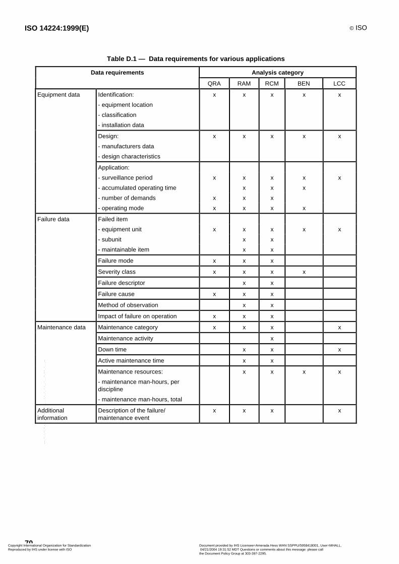
ISO 14224:1999(E) © ISO
70
Table D.1 — Data requirements for various applications
Data requirements Analysis category
QRA RAM RCM BEN LCC
Equipment data Identification:
- equipment location
- classification
- installation data
x x x x x
Design:
- manufacturers data
- design characteristics
x x x x x
Application:
- surveillance period x x x x x
- accumulated operating time x x x
- number of demands x x x
- operating mode x x x x
Failure data Failed item
- equipment unit x x x x x
- subunit x x
- maintainable item x x
Failure mode x x x
Severity class x x x x
Failure descriptor x x
Failure cause x x x
Method of observation x x
Impact of failure on operation x x x
Maintenance data Maintenance category x x x x
Maintenance activity x
Down time x x x
Active maintenance time x x
Maintenance resources:
- maintenance man-hours, perdiscipline
- maintenance man-hours, total
x x x x
Additionalinformation
Description of the failure/maintenance event
x x x x
Copyright International Organization for Standardization Reproduced by IHS under license with ISO
Document provided by IHS Licensee=Amerada Hess WAN SSPPU/5958418001, User=MHALL, 04/21/2004 19:31:52 MDT Questions or comments about this message: please callthe Document Policy Group at 303-397-2295.
--````,``,,,`,,```,```,`,``,``,`,``````,,`,`,,,`````-`-`,,`,,`,`,,`---
© ISO ISO 14224:1999(E)
71
Bibliography
[1] ISO 6527, Nuclear power plants — Reliability data exchange — General guidelines.
[2] ISO 7385, Nuclear power plants — Guidelines to ensure quality of collected data on reliability.
[3] ISO/IEC 2382-14, Information technology — Vocabulary — Part 14: Reliability, maintainability and availability.
[4] IEC 60085, Thermal evaluation and classification of electrical insulation.
[5] IEC 60300-1, Dependability management — Part 1: Dependability programme management.
[6] IEC 60300-2, Dependability management — Part 2: Dependability programme elements and tasks.
[7] IEC 60300-3-1, Dependability management — Part 3: Application Guide — Section 1: Analysis techniques fordependability: Guide on methodology.
[8] IEC 60300-3-2, Dependability management. Part 3: Application guide — Section 2: Collection of dependabilitydata from the field.
[9] IEC 60300-3-3, Dependability management — Part 3: Application guide — Section 3: Life cycle costing.
[10] IEC 60381-2, Analogue signals for process control systems. Part 2: Direct voltage signals.
[11] IEC 60529, Degree of protection provided by enclosures (IP Code).
[12] IEC 60706-1, Guide on maintainability of equipment. Part 1 — Sections One, Two and Three. Introduction,requirements and maintainability programmes.
[13] IEC 60706-2, Guide on maintainability of equipment. Part 2 — Section Five: Maintainability studies during thedesign phase.
[14] IEC 60706-3: Guide on maintainability of equipment. Part 3 — Section Six and Seven. Verification andcollection, analysis and presentation of data.
[15] IEC 60706-4: Guide on maintainability of equipment. Part 4 — Section Eight: Maintenance and maintenancesupport planning.
[16] BS 4778-11, Section 3.1, Guide to concepts and related definitions.
[17] BS 5760-11, Collection of reliability, availability, maintainability and maintenance support data from the field.
Copyright International Organization for Standardization Reproduced by IHS under license with ISO
Document provided by IHS Licensee=Amerada Hess WAN SSPPU/5958418001, User=MHALL, 04/21/2004 19:31:52 MDT Questions or comments about this message: please callthe Document Policy Group at 303-397-2295.
--````,``,,,`,,```,```,`,``,``,`,``````,,`,`,,,`````-`-`,,`,,`,`,,`---

ISO 14224:1999(E) © ISO
ICS 75.180.10
Price based on 71 pages
Copyright International Organization for Standardization Reproduced by IHS under license with ISO
Document provided by IHS Licensee=Amerada Hess WAN SSPPU/5958418001, User=MHALL, 04/21/2004 19:31:52 MDT Questions or comments about this message: please callthe Document Policy Group at 303-397-2295.
--````,``,,,`,,```,```,`,``,``,`,``````,,`,`,,,`````-`-`,,`,,`,`,,`---