Embed Size (px)
Citation preview

UNCLASSIFIED
UNCLASSIFIED
Notice: NETPDTC is no longer responsible for the content accuracy of the NRTCs. For content issues, contact the servicing Center of Excellence: Center for Surface Combat Systems; (540) 284-1061 or DSN: 234. For course registration, issues, or login issues contact the NRTC Helpdesk at: 1-877-264-8583 DSN: 922-1511 or Email: [email protected] DISTRIBUTION STATEMENT A: Approved for public release; distribution is unlimited.
NONRESIDENT TRAINING COURSE
December 2012
Navy Electricity and Electronics Training
Series Module 15-Principles of Synchros, Servos,
and Gyros
NAVEDTRA 14187A
S/N 0504LP1128912

UNCLASSIFIED
UNCLASSIFIED
DISTRIBUTION STATEMENT A: Approved for public release; distribution is unlimited.
Although the words “he,” “him,” and “his” are used sparingly in this course to enhance communication, they are not intended to be gender driven or to affront or discriminate against anyone.

UNCLASSIFIED
i UNCLASSIFIED
PREFACE
By enrolling in this self-study course, you have demonstrated a desire to improve yourself and the Navy. Remember, however, this self-study course is only one part of the total Navy training program. Practical experience, schools, selected reading, and your desire to succeed are also necessary to successfully round out a fully meaningful training program. THE COURSE: This self-study course is organized into subject matter areas, each containing learning objectives to help you determine what you should learn along with text and illustrations to help you understand the information. The subject matter reflects day-to-day requirements and experiences of personnel in the rating or skill area. It also reflects guidance provided by Enlisted Community Managers (ECMs) and other senior personnel, technical references, instructions, etc., and either the occupational or naval standards, which are listed in the Manual of Navy Enlisted Manpower Personnel Classifications and Occupational Standards, NAVPERS 18068. THE QUESTIONS: The questions that appear in this course are designed to help you understand the material in the text. VALUE: In completing this course, you will improve your military and professional knowledge. Importantly, it can also help you study for the Navy-wide advancement in rate examination. If you are studying and discover a reference in the text to another publication for further information, look it up.
2012 Edition
Published by Center for Surface Combat Systems (CSCS)
NAVSUP Logistics Tracking Number 0504-LP-112-8912

UNCLASSIFIED
ii UNCLASSIFIED
Sailor’s Creed
“I am a United States Sailor. I will support and defend the Constitution of the United States of America and I will obey the orders of those appointed over me. I represent the fighting spirit of the Navy and those who have gone before me to defend freedom and democracy around the world. I proudly serve my country’s Navy combat team with honor, courage and commitment. I am committed to excellence and the fair treatment of all.”

UNCLASSIFIED
iii UNCLASSIFIED
TABLE OF CONTENTS CHAPTER PAGE 1 Synchros….…..…………................................................................ 1-1 2 Servos…………………................................................................... 2-1 3 Gyros…………………………….................................................... 3-1 4 Related Devices.…………………................................................... 4-1 APPENDIX A Glossary......................................................................................... A-1
Course Assignments follow Appendix A

UNCLASSIFIED
iv UNCLASSIFIED
NAVY ELECTRICITY AND ELECTRONICS TRAINING SERIES
The Navy Electricity and Electronics Training Series (NEETS) was developed for use by personnel in many electrical and electronic-related Navy ratings. Written by, and with the advice of, senior technicians in these ratings, this series provides beginners with fundamental electrical and electronic concepts through self-study. The presentation of this series is not oriented to any specific rating structure, but is divided into modules containing related information organized into traditional paths of instruction. The series is designed to give small amounts of information that can be easily digested before advancing further into the more complex material. For a student just becoming acquainted with electricity or electronics, it is highly recommended that the modules be studied in their suggested sequence. Considerable emphasis has been placed on illustrations to provide a maximum amount of information. In some instances, knowledge of basic algebra may be required. Course descriptions and ordering information may be found at https://www.netc.navy.mil then click on the Programs tab, then select the Nonresident Training Courses from the list. Throughout the text of this course and while using technical manuals associated with the equipment you will be working on, you will find the below notations at the end of some paragraphs. The notations are used to emphasize that safety hazards exist and care must be taken or observed.
WARNING AN OPERATING PROCEDURE, PRACTICE, OR CONDITION, ETC., WHICH MAY RESULT IN INJURY OR DEATH IF NOT CAREFULLY OBSERVED OR FOLLOWED.
CAUTION AN OPERATING PROCEDURE, PRACTICE, OR CONDITION, ETC., WHICH MAY RESULT IN DAMAGE TO EQUIPMENT IF NOT CAREFULLY OBSERVED OR FOLLOWED.
NOTE An operating procedure, practice, or condition, etc., which is essential to emphasize.

UNCLASSIFIED
v UNCLASSIFIED
STUDENT FEEDBACK AND QUESTIONS We value your suggestions, questions, and criticisms on our courses. If you would like to communicate with us regarding this course, we encourage you, if possible, to use e-mail or to post your comments on the Community of Practice (COP) page located at https://wwwa.nko.navy.mil/portal/home/. If you write or fax, please use a copy of the Student Comment form that follows this page.
For subject matter questions: E-mail: [email protected] Phone: Comm: 540-284-1061 DSN: 234-4639 Address: COMMANDING OFFICER Center for Surface Combat Systems 5395 First St Dahlgren, VA 22448-5200

UNCLASSIFIED
vi UNCLASSIFIED
Student Comments
Course Title: NEETS Module 15-Principles of Synchros, Servos, and Gyros NAVEDTRA: 14187A Date: ____________ We need some information about you: Rate/Rank and Name: _____________ Command/Unit: _________________________ Street Address: ________________ City: _____________ State/FPO: _____ Zip _____ Your comments, suggestions, etc.:
Privacy Act Statement: Under authority of Title 5, USC 301, information regarding your military status is requested in processing your comments and in preparing a reply. This information will not be divulged without written authorization to anyone other than those within DOD for official use in determining performance.

UNCLASSIFIED
vii UNCLASSIFIED
This page left intentionally blank.

NEETS MODULE 15-Principles of Synchros, Servos, and Gyros
UNCLASSIFIED
1-1 UNCLASSIFIED
1 SYNCHROS
LEARNING OBJECTIVES
After you finish this chapter, you should be able to do the following: 1. Define the term "synchro." 2. State the primary purpose of a synchro. 3. Explain the importance of synchros in naval equipment. 4. Name the two general classifications of synchros. 5. Explain the differences between torque and control synchros. 6. Name the seven functional classes of synchros and list all inputs and outputs. 7. Name the two types of synchro identification codes. 8. Interpret all synchro markings and identify the particular codes used. 9. Draw the five standard schematic symbols for synchros and identify all
connections. 10. Describe the general construction and physical appearance of synchro rotors and
stators. 11. Name the two common types of synchro rotors, giving an application of each. 12. List the different synchro characteristics and give a brief explanation of each. 13. State the advantage of using 400-Hz synchros over 60-Hz synchros. 14. Explain the operation of a basic synchro transmitter and receiver. 15. State the difference between a synchro transmitter and a synchro receiver. 16. List the basic components that compose a torque synchro system. 17. Explain the operation of a simple synchro transmission system. 18. Define the term "correspondence" and explain how it is used in a simple synchro
system. 19. Explain the principle behind reversing the S1 and S3 leads on a synchro receiver
and how this action affects receiver operation. 20. Explain what happens when the rotor leads on a synchro transmitter or receiver
are reversed. 21. State the purposes of differential synchros. 22. Name the two types of differential synchros and give a brief explanation of each. 23. Explain the difference between the torque differential transmitter and the torque
differential receiver. 24. Name the components that make up the TDX and the TDR synchro systems. 25. Explain how the two differential synchro systems add and subtract. 26. State the wiring changes required to convert the differential synchro systems from
subtraction to addition. 27. State the purposes and functions of control synchros. 28. Name the different types of control synchros. 29. Explain how the CX and CDX differ from the TX and TDX.

NEETS MODULE 15-Principles of Synchros, Servos, and Gyros
UNCLASSIFIED
1-2 UNCLASSIFIED
30. Explain the theory and operation of a control transformer. 31. List the basic components that compose a control synchro system. 32. Explain the operation of a control synchro system and how it is used to control a
servo system. 33. State the purpose and function of the synchro capacitor. 34. Explain how synchro capacitors improve the accuracy of synchro systems. 35. Explain the method used to connect synchro capacitors in a circuit. 36. Define single and multispeed synchro systems. 37. State the purposes and functions of multispeed synchro systems. 38. Stale the purposes for zeroing synchros. 39. Name three common synchro zeroing methods and give a brief explanation of
each. 40. Explain the different troubleshooting techniques used in isolating synchro
malfunctions and breakdowns. 1.1 INTRODUCTION
Synchros play a very important role in the operation of Navy equipment. Synchros are found in just about every weapon system, communication system, underwater detection system, and navigation system used in the Navy. The importance of synchros is sometimes taken lightly because of their low failure rate. However, the technician who understands the theory of operation and the alignment procedures for synchros is well ahead of the problem when a malfunction does occur. The term "synchro" is an abbreviation of the word "synchronous." It is the name given to a variety of rotary, electromechanical, position-sensing devices. Figure 1-1 shows a phantom view of typical synchro. A synchro resembles a small electrical motor in size and appearance and operates like a variable transformer. The synchro, like the transformer, uses the principle of electromagnetic induction.

NEETS MODULE 15-Principles of Synchros, Servos, and Gyros
UNCLASSIFIED
1-3 UNCLASSIFIED
Synchros are used primarily for the rapid and accurate transmission of information between equipment and stations. Examples of such information are changes in course, speed, and range of targets or missiles; angular displacement (position) of the ship's rudder; and changes in the speed and depth of torpedoes. This information must be transmitted quickly and accurately. Synchros can provide this speed and accuracy. They are reliable, adaptable, and compact. Figure 1-2 shows a simple synchro system that can be used to transmit different as of data or information In this system, a single synchro transmitter furnishes information to two synchro receivers located in distant spaces. Operators put information into the system by turning the handwheel. As the handwheel turns, its attached gear rotates the transmitter shaft (which has a dial attached to indicate the value of the transmitted information). As the synchro transmitter shaft turns, it converts the mechanical input into an electrical signal, which is sent through interconnecting wiring to the two synchro receivers. The receiver shafts rotate in response to the electrical signal from the transmitter. When these shafts turn, the dials attached to the shafts indicate the transmitted information.
Figure 1-1 Phantom view of a synchro

NEETS MODULE 15-Principles of Synchros, Servos, and Gyros
UNCLASSIFIED
1-4 UNCLASSIFIED
By studying the simple synchro system, you can see that information can be transmitted over long distances, from space to space, and from equipment to equipment. In addition to supplying data by positioning dials and pointers, synchros are also used as control devices in servo systems. When the synchro and the servo are combined, they work as a team to move and position heavy loads. The methods used to accomplish this are covered in detail in the next chapter. Q-1. What is the name given to a variety of rotary electromechanical, position sensing devices?
Q-2. What is the primary purpose of a synchro system?
Figure 1-2 Data transfer with synchros

NEETS MODULE 15-Principles of Synchros, Servos, and Gyros
UNCLASSIFIED
1-5 UNCLASSIFIED
1.2 SYNCHRO CLASSIFICATION
Synchros work in teams. Two or more synchros interconnected electrically form a synchro system. There are two general classifications of synchro systems—TORQUE SYSTEMS AND CONTROL SYSTEMS. Torque-synchro systems use torque synchros and control-synchro systems use control synchros. The load dictates the type of synchro system, and thus the type of synchro. Torque-synchro systems are classified "torque" because they are mainly concerned with the torque or turning force required to move light loads such as dials, pointers, or similar indicators. The positioning of these devices requires a relatively low amount of torque. Control synchros are used in systems that are designed to move heavy loads such as gun directors, radar antennas, and missile launchers. In addition to the two general classifications, synchros are grouped into seven basic functional classes as shown in table 1-1. Four of these are the torque type and three are the control type. Each synchro is described in the table by name, abbreviation, input, output, and the other synchro units that may be connected to it. Generally, torque and control synchros may not be interchanged. The functional operation of each of these seven synchros is covered later in this text.
FUNCTIONAL CLASSIFICATION
ABBREVIATION INPUT OUTPUT
Torque transmitter TX Mechanical input to rotor (rotor energized from AC source)
Electrical output from stator representing angular position of rotor to TDX, TDR, or TR.
Control transmitter CX Same as TX Same as TX except it is supplied to CDX or CT
Torque differential transmitter
TDX Mechanical input to rotor, electrical input to stator from TX or another TDX.
Electric output from rotor representing algebraic sum or difference between rotor angle and angle represented by electrical input to TR, TDR, or another TDX.
Control differential transmitter
CDX Same as TDX except electrical input is from CX or another CDX.
Same as TDX except output to CT or another CDX.
Torque receiver TR Electrical input to stator from TX or TDX. (Rotor energized from AC source)
Mechanical output from rotor. Note: Rotor has mechanical inertia damper.

NEETS MODULE 15-Principles of Synchros, Servos, and Gyros
UNCLASSIFIED
1-6 UNCLASSIFIED
Torque differential receiver
TDR Electrical input to stator from TX or TDX, another electrical input to rotor from TX or TDX.
Mechanical output from rotor representing algebraic sum or difference between angles represented by electrical inputs. Has inertia damper.
Control transformer CT Electric input to stator from CX or CDX, mechanical input to rotor.
Electrical output from rotor proportional to the sine of the angle between rotor position and angle represented by electrical input to stator. Called error signal.
Torque receiver TRX Depending on application, same as TX.
Depending on application, same as TX or TR.
Table 1-1 Synchro Information Synchros are also classified according to their operating frequency. This classification was brought about by the development of the 400-Hz synchro. Prior to this time, the 60-Hz synchro was the only one in use. Synchro operating frequencies are covered in detail in the section on synchro characteristics. Q-3. Name the two general classifications of synchro systems.
Q-4. What is the difference between a torque synchro and a control synchro?
Q-5. Using table 1-1, name two synchros that provide a mechanical output.

NEETS MODULE 15-Principles of Synchros, Servos, and Gyros
UNCLASSIFIED
1-7 UNCLASSIFIED
1.3 STANDARD MARKINGS AND SYMBOLS
Synchros used in the Navy can be grouped into two broad categories: MILITARY STANDARD SYNCHROS and PRESTANDARD NAVY SYNCHROS. Military standard synchros conform to specifications that are uniform throughout the armed services. New varieties of equipment use synchros of this type. Prestandard synchros were designed to meet Navy, rather than servicewide, specifications. Each category has its own designation code for identification. 1.3.1 Military Standard Synchro Code
The military standard designation code identifies standard synchros by their physical size, functional purpose, and supply voltage characteristics. The code is alphanumerical and is broken down in the following manner. The first two digits indicate the diameter of the synchro in tenths of an inch, to the next higher tenth. For example, a synchro with a diameter of 1.75 inches has the numeral 18 as its first two digits. The first letter indicates the general function of the synchro and of the synchro system-C for control or T for torque. The next letter indicates the specific function of the synchro, as follows:
LETTER DEFINITION D Differential R Receiver T Transformer X Transmitter If the letter B follows the specific function designation, the synchro has a rotatable stator. The last number in the designation indicates the operating frequency-6 for 60 Hz and 4 for 400 Hz. The upper-case letter following the frequency indicator is the modification designation. The letter "A" indicates that the synchro design is original. The first modification is indicated by the letter "B." Succeeding modifications are indicated by the letters "C," "D," and so on, except for the unused letters "I," "L," "O," and "Q." For example, an 18TR6A synchro is an original design, 60-Hz torque receiver with a diameter of between 1.71 and 1.80 inches. A synchro designated 16CTB4B is the first modification of a 400-Hz control transformer with a rotatable stator and a diameter of between 1.51 and 1.60 inches. All standard synchros are labeled with such a code. Synchros used in circuits supplied by 26 volts are classified in the same way, except that the symbol 26V is prefixed to the designator (for example, 26V-16CTB4A). Otherwise, a 115 volts source is assumed for the synchro system.

NEETS MODULE 15-Principles of Synchros, Servos, and Gyros
UNCLASSIFIED
1-8 UNCLASSIFIED
1.3.2 Navy Prestandard Synchro Code
The Navy prestandard designation code identifies prestandard synchros by size and function, using a number and letter combination. Unlike the standard code, the number does not indicate directly the diameter of the synchro. The number merely represents the approximate size of the synchro, increasing as the size increases. The approximate size and weight of the five most common sizes are shown in the following table.
SIZE APPROX. DIAMETER
APPROX. LENGTH
APPROX WEIGHT
1 2 1/4 in 4 in 2 lb 3 3 1/10 in 5 3/8 in 3 lb 5 3 3/8 to 3 5/8 in 6 1/2 in 5 lb 6 4 1/2 in 7 in 8 lb 7 5 3/4 in 9 in 18 lb
Note that prestandard size 1 is approximately the same size as standard size 23 (2.21 to 2.30 inches in diameter). Prestandard size 3 is approximately the same size as standard size 31. Prestandard size 5 is approximately the same size as standard size 37. The letters used in the prestandard coding system indicate the function, mounting, or special characteristics of the synchro as shown in the following chart.
LETTER DEFINITION G Transmitter F Flange Mounted Receiver (this letter is normally
omitted if letters other than H or S occur in type designation)
D Differential Receiver DG Differential Transmitter CT Control Transformer H High-Speed Unit B Bearing Mounted Unit N Nozzle Mounted Unit S Special Unit Navy prestandard synchros are rarely used today. They have been replaced by the standard synchro. However, by being familiar with the prestandard coding system, you will be able to identify the older synchros and make correct replacements if necessary. Q-6. What does the code 26V-11TX4D mean on a synchro nameplate?
Q-7. Which of the two synchro designation codes is indicated by 5DG on a synchro nameplate?

NEETS MODULE 15-Principles of Synchros, Servos, and Gyros
UNCLASSIFIED
1-9 UNCLASSIFIED
1.3.3 Schematic Symbols
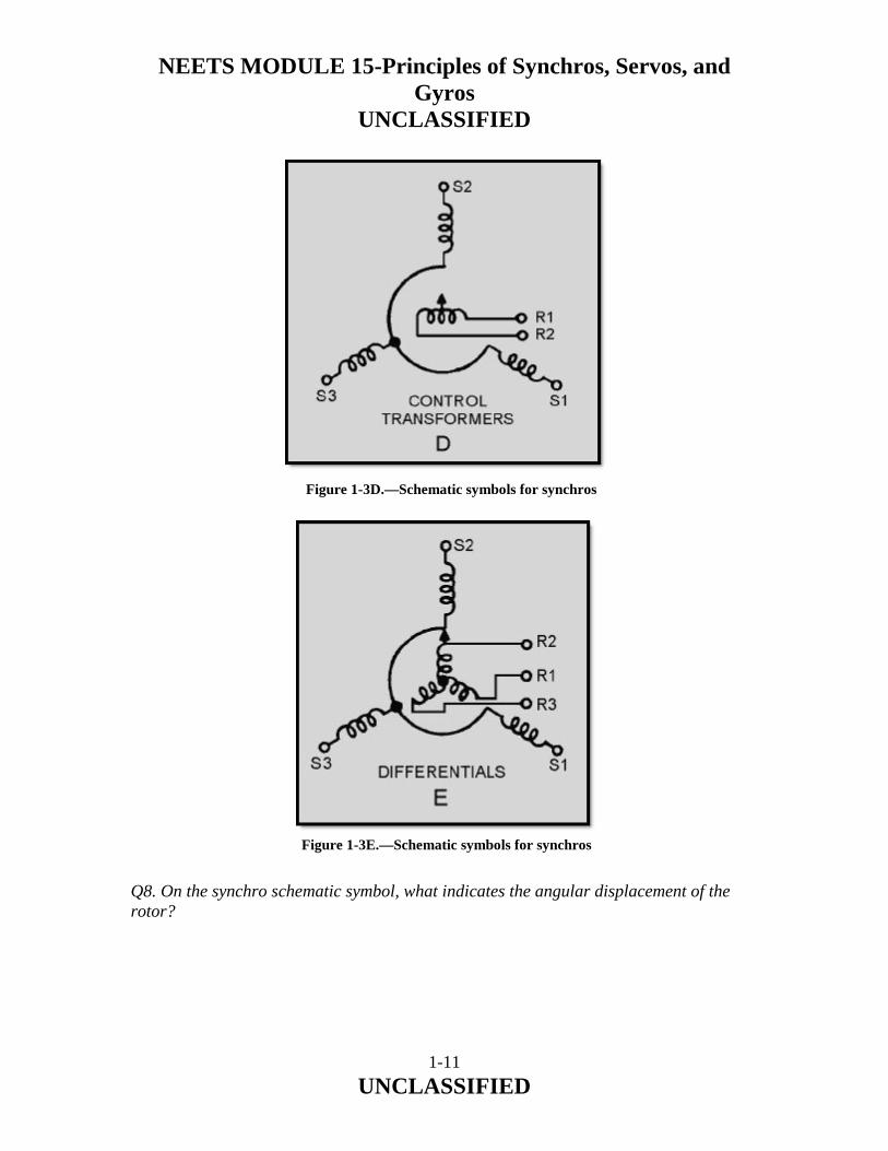
Schematic symbols for synchros are drawn by various manufacturers in many different ways. Only five symbols (as shown in figure 1-3), however, meet the standard military specifications for schematic diagrams of synchros and synchro connections. When a symbol is used on a schematic, it will be accompanied by the military abbreviation of one of the eight synchro functional classifications (TR, TX, TDX, etc.). The symbols shown in views A and B of figure 1-3 are used when it is necessary to show only the external connections to a synchro, while those shown in views C, D, and E are used when it is important to see the positional relationship between the rotor and stator. The letters R and S, in conjunction with an Arabic number, are used to identify the rotor and stator connections; for example, R1, R2, S1, S2, and S3.The small arrow on the rotor symbol indicates the angular displacement of the rotor; in figure 1-3 the displacement is zero degrees.
Figure 1-3A Schematic symbols for synchros

NEETS MODULE 15-Principles of Synchros, Servos, and Gyros
UNCLASSIFIED
1-10 UNCLASSIFIED
Figure 1-3B.—Schematic symbols for synchros
Figure 1-3C.—Schematic symbols for synchros
NEETS MODULE 15-Principles of Synchros, Servos, and Gyros
UNCLASSIFIED
1-11 UNCLASSIFIED
Q8. On the synchro schematic symbol, what indicates the angular displacement of the rotor?
Figure 1-3D.—Schematic symbols for synchros
Figure 1-3E.—Schematic symbols for synchros

NEETS MODULE 15-Principles of Synchros, Servos, and Gyros
UNCLASSIFIED
1-12 UNCLASSIFIED
1.4 SYNCHRO CONSTRUCTION
Figure 1-4 shows a cutaway view of a typical synchro. Having the knowledge of how a synchro is constructed should enable you to better understand how synchros operate. In this section we will discuss how rotors and stators are constructed and how the synchro is assembled. Each synchro contains a rotor, similar in appearance to the armature in a motor, and a stator, which corresponds to the field in a motor. The synchro stator is composed of three Y-connected windings (S1, S2, and S3). The rotor is composed of one single winding (R1 and R2). As you can see in the figure, the rotor winding is free to turn inside the stator. The rotor is usually the primary winding and receives its voltage (excitation) from an external voltage source. The stator receives its voltage from the rotor by magnetic coupling.
Figure 1-4 Typical synchro assembly

NEETS MODULE 15-Principles of Synchros, Servos, and Gyros
UNCLASSIFIED
1-13 UNCLASSIFIED
1.5 ROTOR CONSTRUCTION
There are two common types of synchro rotors in use-the SALIENT-POLE ROTOR and the DRUM or WOUND ROTOR. The salient-pole rotor shown in figure 1-5 has a single coil wound on a laminated core. The core is shaped like a "dumb-bell" or the letter "H." This type of winding is frequently used in both transmitters and receivers. The drum or wound rotor has coils wound in slots in a laminated core as shown in figure 1-6. This type of rotor is used in most synchro control transformers and differential units, and occasionally in torque transmitters. It may be wound continuously with a single length of wire or may have a group of coils connected in series. The single continuous winding provides a distributed winding effect for use in transmitters. When the rotor is wound with a group of coils connected in series, a concentrated winding effect is provided for use in control transformers. When used in differential units, the rotor is wound with three coils so their magnetic axes are 120º apart.
Figure 1-5 Salient-pole rotor

NEETS MODULE 15-Principles of Synchros, Servos, and Gyros
UNCLASSIFIED
1-14 UNCLASSIFIED
Both types of synchro rotors have their coils wound on laminated cores that are rigidly mounted on a shaft. To enable the excitation voltage to be applied to the rotor winding, two slip rings are mounted on one end of the shaft and insulated from the shaft to prevent shorting. An insulated terminal board, mounted on the end of the cylindrical frame, houses the brushes, which ride on the slip rings. These brushes provide continuous electrical contact to the rotor during its rotation. Also mounted on the rotor shaft are low-friction ball bearings, which permit the rotor to turn easily. 1.6 STATOR CONSTRUCTION
The stator of a synchro is a cylindrical structure of slotted laminations on which three Y-connected coils are wound with their axes 120º apart. In figure 1-7, view A shows a typical stator assembly consisting of the laminated stator, stator windings, and cylindrical frame; view B shows the stator lamination and the slots in which the windings are placed. Some synchros are constructed so both the stator and the rotor may be turned. Electrical connections to this type of stator are made through slip rings and brushes.
Figure 1-6 Drum or wound rotor

NEETS MODULE 15-Principles of Synchros, Servos, and Gyros
UNCLASSIFIED
1-15 UNCLASSIFIED
Figure 1-7A Typical stator
Figure 1-7B.—Stator lamination

NEETS MODULE 15-Principles of Synchros, Servos, and Gyros
UNCLASSIFIED
1-16 UNCLASSIFIED
Now, refer to figure 1-4 for a view of a completed synchro assembly. The rotor has been placed in the stator assembly, and a terminal board has been added to provide a point at which internal and external connections can be made. Q-9. What are the two major components of a synchro?
Q-10. Which of the two main types of rotors can have either a single winding or three Y-connected windings?
Q-11. How does the stator receive its voltage?
Q-12. Where are the external connections made on standard synchros?

NEETS MODULE 15-Principles of Synchros, Servos, and Gyros
UNCLASSIFIED
1-17 UNCLASSIFIED
1.7 SYNCHRO CHARACTERISTICS
Synchro characteristics play a very important part in synchro troubleshooting and maintenance. By closely observing these characteristics, you can generally tell if a synchro or synchro system is working properly. Low torque, overheating, and improper operating voltages are just a few of the abnormal characteristics found in synchro systems. In general, the load capacity of a synchro system is limited by the number and types of receiver units loading the transmitter, the loads on these receiver units, and the operating temperature. 1.7.1 Torque
Torque is simply a measure of how much load a machine can turn. In torque synchros, only small loads are turned; therefore, only a small amount of torque is required. The measure of torque is the product of the applied force and the distance between the point of application and the center of rotation. For instance, if a 3 ounce weight is suspended from a synchro pulley having a radius of 2 inches, the torque required to move the weight is 6 ounce-inches. In heavy machinery, torque may be expressed in pound-feet, but torque synchro measurements are in ounce-inches. NOTE: The unit of torque is the pound-foot or ounce-inch. Do not confuse this with foot-pounds, which is the measurement of work. Many times in referring to torque, tools are marked in foot-pounds. While this use of foot-pounds is technically incorrect, common usage has made it acceptable. The torque developed in a synchro receiver results from the tendency of two electromagnets to align themselves. Since the rotor can be turned and the stator usually cannot, the stator must exert a force (torque) tending to pull the rotor into a position where the primary and secondary magnetic fields are in line. The strength of the magnetic field produced by the stator determines the torque. The field strength depends on the current through the stator coils. As the current through the stator is increased, the field strength increases and more torque is developed. Q-13. What major factors determine the load capacity of a torque-synchro transmitter?
Q-14. Define the term "torque."
Q-15. What unit of measurement refers to the torque of a synchro transmitter?

NEETS MODULE 15-Principles of Synchros, Servos, and Gyros
UNCLASSIFIED
1-18 UNCLASSIFIED
1.7.2 Operating Voltages and Frequencies
Military standard and Navy prestandard synchros are designed to operate on either 115 volts or 26 volts. Synchros used in shipboard equipment are designed predominately for 115 volts, while most aircraft synchros operate on 26 volts. Synchros are also designed to operate on a 60- or 400-Hz frequency. But like transformers, they are more efficient at the higher frequency. Operating a synchro at a higher frequency also permits it to be made physically smaller. This is because the lines of flux produced by the 400-Hz excitation voltage are much more concentrated than those produced by the 60-Hz excitation voltage. Hence, the core of the 400- Hz synchro can be made smaller than the core of the 60-Hz synchro. However, some 400-Hz synchro units are identical in size to their 60-Hz counterparts. This is done so that 60- and 400-Hz units can be physically interchanged without special mounting provisions. The operating voltage and frequency of each synchro is marked on its nameplate. The use of the smaller size synchro permits the construction of smaller and more compact equipment. The most widely used frequency for airborne equipment is 400 Hz. It is being used increasingly in shipboard equipment as well. The newer gun and missile fire-control systems use 400-Hz synchros almost exclusively. A synchro designed for 60-Hz operation may occasionally be used with a 400-Hz supply. There may be considerable loss of accuracy, but the synchro will not be damaged. This should be done only in the case of an emergency when the specified replacement is not available, and system accuracy is not critical.
CAUTION NEVER connect a 400-Hz synchro to 60-Hz voltage. The reduced impedance results in excessive current flow and the windings quickly burn out. Q-16. What type of equipment normally uses 26-volt 400-hertz synchros?

NEETS MODULE 15-Principles of Synchros, Servos, and Gyros
UNCLASSIFIED
1-19 UNCLASSIFIED
1.7.3 Operating Temperatures and Speeds
Standard synchros are designed to withstand surrounding temperatures ranging from −67º F to +257º F (-55º C to +125º C) at the terminal board. Prestandard synchros operate in a range of −13º F to +185º F (-25º C to +85º C). When a synchro is energized and not loaded, its temperature should stay within prescribed limits. Loading an energized synchro causes it to generate more heat. Similarly, overloading causes a synchro to generate much more heat than it would under normal loading conditions and could possibly result in permanent synchro damage. To meet military specifications, all standard synchros must be capable of continuous operation for 1,000 hours at 1,200 revolutions per minute (rpm) without a load. A prestandard synchro has one of two specifications, depending upon its use in a data transmission system. Low-speed prestandard synchros must be capable of continuous operation for 500 hours at 300 rpm without a load. Low-speed prestandard synchros must be capable of continuous operation for 1,500 hours at 1200 rpm without a load. Q-17. When will a synchro generate more heat than it is designed to handle?
1.8 THEORY OF OPERATION
Synchros, as stated earlier, are simply variable transformers. They differ from conventional transformers by having one primary winding (the rotor), which may be rotated through 360º and three stationary secondary windings (the stator) spaced 120º apart. It follows that the magnetic field within the synchro may also be rotated through 360º. If an iron bar or an electromagnet were placed in this field and allowed to turn freely, it would always tend to line up in the direction of the magnetic field. This is the basic principle underlying all synchro operations. We will begin the discussion of synchro operation with a few basic points on electromagnets. Look at figure 1-8. In this figure, a simple electromagnet is shown with a bar magnet pivoted in the electromagnet's field. In view A, the bar is forced to assume the position shown, since the basic law of magnetism states that like poles of magnets repel and unlike poles attract. Also notice that when the bar is aligned with the field, the magnetic lines of force are shortest. If the bar magnet is turned from this position and held as shown in view B, the flux is distorted and the magnetic lines of force are lengthened. In this condition, a force (torque) is exerted on the bar magnet. When the bar magnet is released, it snaps back to its original position. When the polarity of the electromagnet is reversed, as shown in view C, the field reverses and the bar magnet is rotated 180º from its original position.

NEETS MODULE 15-Principles of Synchros, Servos, and Gyros
UNCLASSIFIED
1-20 UNCLASSIFIED
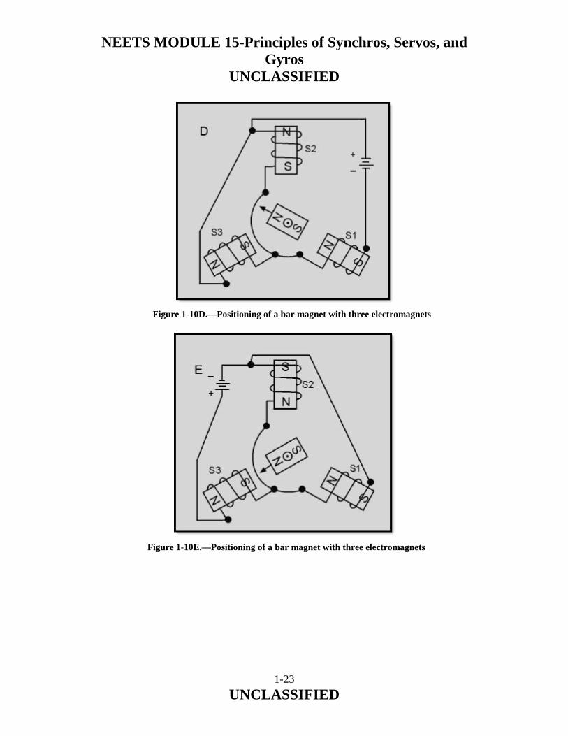
Keeping in mind these basic points, consider how the bar magnet reacts to three electromagnets spaced 120º apart as illustrated in figure 1-9. In this figure, stator coils S1 and S3, connected in parallel, together have the same field strength as stator coil S2. The magnetic field is determined by current flow through the coils. The strongest magnetic field is set up by stator coil S2, since it has twice the current and field strength as either S1 or S3 alone. A resultant magnetic field is developed by the combined effects of the three stator fields. Coil S2 has the strongest field, and thus, the greatest effect on the resultant field, causing the field to align in the direction shown by the vector in view B of the figure. The iron-bar rotor aligns itself within the resultant field at the point of greatest flux density. By convention, this position is known as the zero-degree position. The rotor can be turned from this position to any number of positions by applying the proper combination of voltages to the three coils, as illustrated in figure 1-10, view (A), view (B), view (C), view (D), view (E), view (F).
Figure 1-8 Operation of an electromagnet with a bar-magnet rotor

NEETS MODULE 15-Principles of Synchros, Servos, and Gyros
UNCLASSIFIED
1-21 UNCLASSIFIED
Figure 1-9 Operation of three electromagnets spaced 120º apart
Figure 1-10A Positioning of a bar magnet with three electromagnets

NEETS MODULE 15-Principles of Synchros, Servos, and Gyros
UNCLASSIFIED
1-22 UNCLASSIFIED
Figure 1-10B.—Positioning of a bar magnet with three electromagnets
Figure 1-10C.—Positioning of a bar magnet with three electromagnets
NEETS MODULE 15-Principles of Synchros, Servos, and Gyros
UNCLASSIFIED
1-23 UNCLASSIFIED
Figure 1-10D.—Positioning of a bar magnet with three electromagnets
Figure 1-10E.—Positioning of a bar magnet with three electromagnets

NEETS MODULE 15-Principles of Synchros, Servos, and Gyros
UNCLASSIFIED
1-24 UNCLASSIFIED
Notice in figure 1-10, in views A C, and E, that the rotor positions are achieved by shifting the total current through different stator windings (S1, S2, and S3). This causes the rotor to move toward the coil with the strongest magnetic field. To obtain the rotor positions in views B, D, and F, it was necessary only to reverse the battery connections. This causes the direction of current flow to reverse and in turn reverses the direction of the magnetic field. Since the rotor follows the magnetic field the rotor also changes direction. By looking closely at these last three rotor positions, you will notice that they are exactly opposite the first three positions we discussed. This is caused by the change in the direction of current flow. You can now see that by varying the voltages to the three stator coils, we can change the current in these coils and cause the rotor to assume any position we desire. In the previous examples, dc voltages were applied to the coils. Since synchros operate on ac rather than dc, consider what happens when ac is applied to the electromagnet in figure 1-11. During one complete cycle of the alternating current, the polarity reverses twice.
Figure 1-10F.—Positioning of a bar magnet with three electromagnets

NEETS MODULE 15-Principles of Synchros, Servos, and Gyros
UNCLASSIFIED
1-25 UNCLASSIFIED
Therefore, the number of times the polarity reverses each second is twice the excitation frequency, or 120 times a second when a 60-Hz frequency is applied. Since the magnetic field of the electromagnet follows this alternating current, the bar magnet is attracted in one direction during one-half cycle (view A) and in the other direction during the next half cycle (view B). Because of its inertia, the bar magnet cannot turn rapidly enough to follow the changing magnetic field and may line up with either end toward the coil (view C). This condition also causes weak rotor torque. For these reasons, the iron-bar rotor is not practical for ac applications. Therefore, it must be replaced by an electromagnetic rotor as illustrated in figure 1-12.
Figure 1-11 Operation of an electromagnet with ac voltage

NEETS MODULE 15-Principles of Synchros, Servos, and Gyros
UNCLASSIFIED
1-26 UNCLASSIFIED
In this figure, both stationary and rotating coils are connected to the same 60-Hz source. During the positive alternation (view A), the polarities are as shown and the top of the rotor is attracted to the bottom of the stationary coil. During the negative alternation (view B), the polarities of both coils reverse, thus keeping the rotor aligned in the same position. In summary, since both magnetic fields change direction at the same time when following the 60-Hz ac supply voltage, the electromagnetic rotor does not change position because it is always aligned with the stationary magnetic field. Q-18. How do synchros differ from conventional transformers?
Q-19. Describe the zero-position of a synchro transmitter.
Figure 1-12 Operation of fixed and moveable electromagnets with ac voltage

NEETS MODULE 15-Principles of Synchros, Servos, and Gyros
UNCLASSIFIED
1-27 UNCLASSIFIED
1.9 SYNCHRO TORQUE TRANSMITTER
The synchro transmitter converts the angular position of its rotor (mechanical input) into an electrical output signal. When a 115-volt ac excitation voltage is applied to the rotor of a synchro transmitter, such as the one shown in figure 1-13, the resultant current produces an ac magnetic field around the rotor winding. The lines of force cut through the turns of the three stator windings and, by transformer action, induce voltage into the stator coils. The effective voltage induced in any stator coil depends upon the angular position of hat coil's axis with respect to the rotor axis. When the maximum effective coil voltage is known, the effective voltage induced into a stator coil at any angular displacement can be determined.
Figure 1-13 Synchro transmitter

NEETS MODULE 15-Principles of Synchros, Servos, and Gyros
UNCLASSIFIED
1-28 UNCLASSIFIED
Figure 1-14 illustrates a cross section of a synchro transmitter and shows the effective voltage induced in one stator coil as the rotor is turned to different positions. The turns ratios in synchros may vary widely, depending upon design and application, but there is commonly a 2.2:1 stepdown between the rotor and a single coil. Thus, when 115 volts is applied to the rotor, the highest value of effective voltage induced in any one stator coil is 52 volts. The maximum induced voltage occurs each time there is maximum magnetic coupling between the rotor and the stator coil (views A, C, and E). The effective voltage induced in the secondary winding is approximately equal to the product of the effective voltage on the primary, the secondary-to-primary turns ratio, and the magnetic coupling between primary and secondary. Therefore, because the primary voltage and the turns ratio are constant, it is commonly said that the secondary voltage varies with the angle between the rotor and the stator. When stator voltages are measured, reference is always made to terminal-to-terminal voltages (voltage induced between two stator terminals) instead of to a single coil's voltage. This is because the voltage induced in one stator winding cannot be measured because the common connection between the stator coils is not physically accessible.
Figure 1-14 Stator voltage vs rotor position
NEETS MODULE 15-Principles of Synchros, Servos, and Gyros
UNCLASSIFIED
1-29 UNCLASSIFIED
In summary, the synchro transmitter converts the angular position of its rotor into electrical stator signals, which are sent through interconnecting wires to other synchro devices. Q-20. When is the maximum voltage induced into a stator coil?
Q-21. What three factors determine the amplitude of the voltage induced into a stator winding?
1.10 SYNCHRO TORQUE RECEIVER
Synchro torque receivers, commonly called synchro receivers, are electrically identical to torque transmitters of the same size except for the addition of some form of damping. In some sizes of 400-Hz synchros, units are designated as torque receivers but may be used as either transmitters or receivers. Unlike the transmitter, the receiver has an electrical input to its stator and a mechanical output from its rotor. The synchro receiver's function is to convert the electrical data supplied to its stator from the transmitter, back to a mechanical angular position through the movement of its rotor. This function is accomplished when the rotor is connected to the same ac source as the transmitter and assumes a position determined by the interaction of its magnetic field with the magnetic field of the stator. If you recall, this is the same concept discussed earlier under the operation of electromagnets. Normally, the receiver rotor is unrestrained in movement except for brush and bearing friction. When power is first applied to a system, the transmitter position changes quickly; or if the receiver is switched into the system, the receiver rotor turns to correspond to the position of the transmitter rotor. This sudden motion can cause the rotor to oscillate (swing back and forth) around the synchronous position If the movement of the rotor is great enough, it may even spin. Some method of preventing oscillations or spinning must be used. Any method that accomplishes this task is termed DAMPING.

NEETS MODULE 15-Principles of Synchros, Servos, and Gyros
UNCLASSIFIED
1-30 UNCLASSIFIED
There are two types of damping methods ELECTRICAL and MECHANICAL. In small synchros the electrical method is used more frequently than the mechanical method. This method uses an additional winding placed in the synchro to retard oscillations. In larger units, a mechanical device, known as an inertia damper, is more effective. Several variations of the inertia damper are in use. One of the more common types consists of a heavy brass flywheel (inertia damper), which is free to rotate around a bushing that is attached to the rotor shaft (fig. 1-15). A tension spring on the bushing rubs against the flywheel so that the bushing and flywheel turn together during normal operation. If the rotor shaft turns or tends to change its speed or direction of rotation suddenly, the inertia of the damper opposes the changing condition. Q-22. What is the physical difference between a synchro transmitter and a synchro receiver?
Q-23. What method is used to prevent oscillations in large synchro units?
Figure 1-15 Cutaway view of torque receiver with inertia damper

NEETS MODULE 15-Principles of Synchros, Servos, and Gyros
UNCLASSIFIED
1-31 UNCLASSIFIED
1.11 TORQUE SYNCHRO SYSTEM
A torque transmitter (TX) and a torque receiver (TR) make up a simple torque-synchro system. Basically, the electrical construction of synchro transmitters and receivers is similar, but their intended functions are different. The rotor of a synchro transmitter is usually geared to a manual or mechanical input. This gearing may drive a visual indicator showing the value or quantity being transmitted. The rotor of the receiver synchronizes itself electrically with the position of the rotor of the transmitter and thus responds to the quantity being transmitted. 1.11.1 Basic Synchro System Operation
A simple synchro transmission system consisting of a torque transmitter connected to a torque receiver (TX-TR) is illustrated in figure 1-16. As you can see, in this system the rotors are connected in parallel across the ac line. The stators of both synchros have their leads connected S1 to S1, S2 to S2, and S3 to S3, so the voltage in each of the transmitter stator coils opposes the voltage in the corresponding coils of the receiver. The voltage directions are indicated by arrows for the instant of time shown by the dot on the ac line voltage.
Figure 1-16 A simple synchro transmission system

NEETS MODULE 15-Principles of Synchros, Servos, and Gyros
UNCLASSIFIED
1-32 UNCLASSIFIED
When both transmitter and receiver rotors in a synchro system are on zero or displaced from zero by the same angle, a condition known as CORRESPONDENCE exists. In view A of figure 1-16, the transmitter and receiver are shown in correspondence. In this condition, the rotor of the TR induces voltages in its stator coils (S2 = 52V; S1 and S3 = 26V) that are equal to and opposite the voltages induced into the TX stator coils (S2 = 52V; S1 and S3 = 26V). This causes the voltages to cancel and reduces the stator currents to zero. With zero current through the coils, the receiver torque is zero and the system remains in correspondence. The angle through which a transmitter rotor is mechanically rotated is called a SIGNAL. In view B of figure 1-16, the signal is 60º. Now, consider what happens to the two synchros in correspondence when this signal is generated. When the transmitter rotor is turned, the rotor field follows and the magnetic coupling between the rotor and stator windings changes. This results in the transmitter S2 coil voltage decreasing to 26 volts, the S3 coil voltage reversing direction, and the S1 coil voltage increasing to 52 volts. This imbalance in voltages, between the transmitter and receiver, causes current to flow in the stator coils in the direction of the stronger voltages. The current flow in the receiver produces a resultant magnetic field in the receiver stator in the same direction as the rotor field in the transmitter. A force (torque) is now exerted on the receiver rotor by the interaction between its resultant stator field and the magnetic field around its rotor. This force causes the rotor to turn through the same angle as the rotor of the transmitter. As the receiver approaches correspondence, the stator voltages of the transmitter and receiver approach equality. This action decreases the stator currents and produces a decreasing torque on the receiver. When the receiver and the transmitter are again in correspondence, as shown in view C, the stator voltages between the two synchros are equal and opposite (S1 = 52V; S2 and S3 = 26V), the rotor torque is zero, and the rotors are displaced from zero by the same angle (60º). This sequence of events causes the transmitter and receiver to stay in correspondence. In the system we just explained, the receiver reproduced the signal from the transmitter. As you can see, a synchro system such as this could provide a continuous, accurate, visual reproduction of important information to remote locations. Q-24. What two components make up a simple synchro transmission system?
Q-25. What leads in a simple synchro system are connected to the ac power line?

NEETS MODULE 15-Principles of Synchros, Servos, and Gyros
UNCLASSIFIED
1-33 UNCLASSIFIED
Q-26. What is the relationship between the transmitter and receiver stator voltages when their rotors are in correspondence?
Q-27. What is the name given to the angle through which a transmitters rotor is mechanically rotated?
1.11.1.1 Receiver Rotation
When the teeth of two mechanical gears are meshed and a turning force is applied, the gears turn in opposite directions. If a third gear is added, the original second gear turns in the same direction as the first. This is an important concept, because the output of a synchro receiver is often connected to the device it operates through a train of mechanical gears. Whether or not the direction of the force applied to the device and the direction in which the receiver rotor turns are the same depends on whether the number of gears in the train is odd or even. The important thing, of course, is to move the dial or other device in the proper direction. Even when there are no gears involved, the receiver rotor may turn in the direction opposite to the direction you desire. To correct this problem, some method must be used to reverse the receiver's direction of rotation. In the transmitter-receiver system, this is done by reversing the S1 and S3 connections so that SI of the transmitter is connected to S3 of the receiver and vice versa (fig. 1-17), view (A) and view (B).
Figure 1-17A Effect of reversing the S1 and S3 connections between the transmitter and the receiver

NEETS MODULE 15-Principles of Synchros, Servos, and Gyros
UNCLASSIFIED
1-34 UNCLASSIFIED
Even when the S1 and S3 connections are reversed, the system at 0º acts the same as the basic synchro system we previously described at 0º. This is because the voltages induced in the S1 and S3 stator windings are still equal and oppose each other. This causes a canceling effect, which results in zero stator current and no torque. Without the torque required to move the receiver rotor, the system remains in correspondence and the reversing of the stator connections has no noticeable effect on the system at 0º. Suppose the transmitter rotor is turned counterclockwise 60º, as shown in view A of figure 1-17. The TX rotor is now aligned with S1. This results in maximum magnetic coupling between the TX rotor and the S1 winding. This maximum coupling induces maximum voltage in S1. Because S1 is connected to S3 of the TR, a voltage imbalance occurs between them. As a result of this voltage imbalance, maximum current flows through the S3 winding of the TR causing it to have the strongest magnetic field. Because the other two fields around S2 and S1 decrease proportionately, the S3 field has the greatest effect on the resultant TR stator field. The strong S3 stator field forces the rotor to turn 60º clockwise into alignment with itself, as shown in view B. At this point, the rotor of the TR induces canceling voltages in its own stator coils and causes the rotor to stop. The system is now in correspondence. Notice that by reversing S1 and S3, both synchro rotors turn the same amount, but in OPPOSITE DIRECTIONS. We must emphasize that the only stator leads ever interchanged, for the purpose of reversing receiver rotation, are S1 and S3. S2 cannot be reversed with any other lead since it represents the electrical zero position of the synchro. As you know, the stator leads in a synchro are 120º apart. Therefore, any change in the S2 lead causes a 120º error in the synchro system and also reverses the direction of rotation.
Figure 1-17B.—Effect of reversing the S1 and S3 connections between the transmitter and the receiver
NEETS MODULE 15-Principles of Synchros, Servos, and Gyros
UNCLASSIFIED
1-35 UNCLASSIFIED
In new or modified synchro systems, a common problem is the accidental reversal of the R1 and R2 leads on either the transmitter or receiver. This causes a 180º error between the two synchros, but the direction of rotation remains the same. Q-28. What two receiver leads are reversed to reverse the rotor's direction of rotation?
Q-29. What is the most likely problem if the transmitter shaft reads 0º when the receiver shaft indicates 180º?
1.11.2 Torque Differential Synchro Systems
The demands on a synchro system are not always as simple as positioning an indicating device in response to information received from a single source (transmitter). For example, an error detector used in checking weapons equipment uses a synchro system to determine the error in a gun's position with respect to the positioning order. To do this, the synchro system must accept two signals, one containing the positioning order and the other corresponding to the actual position of the gun. The system must then compare the two signals and position an indicating dial to show the difference between them, which is the error. Obviously, the simple synchro transmitter-receiver system discussed so far could not handle a job of this sort. A different type of synchro is needed, one which can accept two signals simultaneously, add or subtract the signals, and furnish an output proportional to their sum or difference. This is where the SYNCHRO DIFFERENTIAL enters the picture. A differential can perform all of these functions. There are two types of differential units - differential transmitters and differential receivers. The differential transmitter (TDX) accepts one electrical input and one mechanical input and produces one electrical output. The differential receiver (TDR) accepts two electrical inputs and produces one mechanical output. A comparison of the TDX and TDR is shown in figure 1-18. The torque differential transmitter and the torque differential receiver can be used to form a DIFFERENTIAL SYNCHRO SYSTEM. The system can consist either of a torque transmitter (TX), a torque differential transmitter (TDX), and a torque receiver (TR), (TX-TDX-TR); or two torque transmitters (TXs) and one torque differential receiver (TDR), (TX-TDR-TX). Before beginning a discussion of the systems using differentials, we need to provide a brief explanation on the newly introduced synchros, the TDX and the TDR.

NEETS MODULE 15-Principles of Synchros, Servos, and Gyros
UNCLASSIFIED
1-36 UNCLASSIFIED
1.11.2.1 Torque Differential Transmitter
In the torque differential transmitter, BOTH the rotor and stator windings consist of three Y-connected coils, as illustrated in view A of figure 1-19. The stator is normally the primary, and receives its input signal from a synchro transmitter. The voltages appearing across the differential's rotor terminals (R1, R2, and R3) are determined by the magnetic field produced by the stator currents, the physical positioning of the rotor, and the step-up turns ratio between the stator and the rotor. The magnetic field, created by the stator currents, assumes an angle corresponding to that of the magnetic field in the transmitter supplying the signal. The position of the rotor controls the amount of magnetic coupling that takes place between the stator magnetic field and the rotor, and therefore, the amount of voltage induced into the rotor windings. If the rotor position changes in response to a mechanical input, then the voltages induced into its windings also change. Therefore, the output voltage of the TDX varies as a result of either a change in the input stator voltage or a change in the mechanical input to the rotor. This electrical output of the TDX may be either the SUM or the DIFFERENCE of the two inputs depending upon how the three units (the TX, the TDX, and the TR) are connected.
Figure 1-18 Torque differentials

NEETS MODULE 15-Principles of Synchros, Servos, and Gyros
UNCLASSIFIED
1-37 UNCLASSIFIED
Figure 1-19A Torque differential transmitter
Figure 1-19B.—Torque differential receiver

NEETS MODULE 15-Principles of Synchros, Servos, and Gyros
UNCLASSIFIED
1-38 UNCLASSIFIED
1.11.2.2 Torque Differential Receiver
The torque differential transmitter (TDX) and the torque differential receiver (TDR) are ELECTRICALLY IDENTICAL. The only difference in their construction is that the receiver (TDR) has a damper, which serves the same purposes as the damper in the TR — it prevents the rotor from oscillating. The real difference in the receiver lies in its application. It provides the mechanical output for a differential synchro system usually as the sum or difference of two electrical inputs from synchro transmitters. As in the case with the TDX, the TDR addition or subtraction function depends upon how the units in the system are connected. Basically, the torque differential receiver operates like the electromagnets we discussed earlier in this chapter. In view B, the rotor and stator of the torque differential receiver receive energizing currents from two torque transmitters. These currents produce two resultant magnetic fields, one in the rotor and the other in the stator. Each magnetic field assumes an angle corresponding to that of the magnetic field in the transmitter supplying the signal. It is the interaction of these two resultant magnetic fields that causes the rotor in the TDR to turn. Q-30. What is the purpose of using differential synchros instead of regular synchros?
Q-31. What are the two types of differential synchros?
Q-32. Other than their physical differences, what is the major difference between a TDX and a TDR?
Q-33. What determines whether a differential synchro adds or subtracts?

NEETS MODULE 15-Principles of Synchros, Servos, and Gyros
UNCLASSIFIED
1-39 UNCLASSIFIED
1.11.3 TX-TDX-TR System Operation (Subtraction)
Now that you know how the individual units work, we can continue our discussion with their application in different systems. The following sections explain how the TDX and TDR are used with other synchros to add and subtract. To understand how a TDX subtracts one input from another, first consider the conditions in a TXTDX-TR system when all the rotors are on 0º, as in view A of figure 1-20. In this case, the TDX is on electrical zero and merely passes along the voltages applied to its windings without any change. Therefore, the TX stator voltages are felt at the TDX rotor. With the system in perfect balance, the TDX rotor voltages equal and oppose the TR stator voltages so that no current flows in the circuit. Since there is no current to produce the torque required to move the TR rotor, the system will remain in this condition, thus solving the equation 0º − 0º = 0º.
Figure 1-20A TX-TDX-TR system operation (subtraction)

NEETS MODULE 15-Principles of Synchros, Servos, and Gyros
UNCLASSIFIED
1-40 UNCLASSIFIED
Figure 1-20B.—TX-TDX-TR system operation (subtraction)
Figure 1-20C.—TX-TDX-TR system operation (subtraction)

NEETS MODULE 15-Principles of Synchros, Servos, and Gyros
UNCLASSIFIED
1-41 UNCLASSIFIED
Up to this point, we have discussed the number of degrees a rotor is turned. Now, it is important to point out the labeling of synchro positions. Labeling is necessary to determine the actual position of the synchros rotor. Notice that synchro rotor positions are labeled from 0º, increasing in a counterclockwise direction. It is common practice to refer to a synchro transmitter as being on 120º when its rotor is pointing toward the S3 winding. Do not confuse these positions with the number of degrees a rotor is turned. Assume that a 240º input is applied to the system, as indicated in view B, by turning the TX rotor to its 240º position. At this position maximum voltage is induced into the S1 winding of the TX and coupled to S1 of the TDX. Since the TDX rotor is on 0º, it passes this maximum voltage (via R1) along to the S1 winding of the TR. The stator magnetic field in the receiver now lines up in the direction of the S1 winding and causes the rotor to turn counterclockwise to the 240º position. This illustrates an important point: Whenever the TDX rotor is at 0º, the TR rotor follows the TX rotor exactly. In the present case, the system has just solved the equation 240º − 0º = 240º. Before we go to another example, you need to understand that when you subtract a higher value of degrees from a lower value of degrees, you add 360º to the lower value and subtract directly. For example: 10º - 260º
Add 360º to lower value: 10º + 360º = 370º Subtract: 370º − 260º = 110º
Figure 1-20D.—TX-TDX-TR system operation (subtraction)

NEETS MODULE 15-Principles of Synchros, Servos, and Gyros
UNCLASSIFIED
1-42 UNCLASSIFIED
In the next example, hold the TX rotor on 0º and turn the TDX rotor to 120º, as illustrated in view C of figure 1-20. In this situation, R1 of the TDX has maximum voltage induced in its winding since it is in line with S2. With R1 of the TDX connected to S1 of the TR, the TR stator magnetic field lines up in the direction of S1 and causes the TR rotor to turn clockwise to the 240º position. Given, then, that the TX is on 360º (or the 0º position), and subtracting the 120º displacement of the TDX rotor, the difference is 240º. This is the position at which the TR rotor comes to rest. Therefore, the system has solved the equation 360º − 120º = 240º. The actual subtraction operation of the TDX is a little more apparent in the next example. Now, consider what happens in view D when the TX rotor is turned manually to 75º and the TDX rotor is set manually on 30º. When the TX rotor is turned to 75º, magnetic coupling increases between the rotor and S1. This, in turn, increases the voltage in S1 and, therefore, the magnetic field surrounding it. At the same time, the field in S2 and S3 decreases proportionately. This causes the resultant TX stator field to line up in the direction of its rotor. The increased voltage in S1 of the TX also causes an increase in current flow through S1 in the TDX, while decreased currents flow through S2 and S3. Therefore, a strong magnetic field is established around the S1 winding in the TDX. This field has the greatest effect on the resultant TDX stator field and causes it to line up in the same relative direction as the TX stator field (75º). The TDX stator field does not move from this 75º position because it is controlled by the position of the TX rotor. However, its angular position with respect to the R2 winding decreases by 30 when the TDX rotor is turned. Therefore, the signal induced into the TDX rotor and transmitted to the TR is 45º. The TR rotor responds to the transmitted signal and turns counterclockwise to 45º. This system has just solved the equation 75º −30 º = 45º. 1.11.4 TX-TDX-TR System Operation (Addition)
Frequently it is necessary to set up a TX-TDX-TR system for addition. This is done by reversing the S1 and S3 leads between the TX and the TDX, and the R1 and R3 leads between the TDX and the TR. With these connections, the system behaves as illustrated in figure 1-21. Consider what happens when the TX rotor is turned to 75º, while the TDX is set at 0º view A. In the TX, with the rotor at 75º, increased coupling between the rotor and S1 increases the current in, and consequently the magnetic field around, that coil. At the same time, the field strengths of S2 and S3 decrease proportionately. This causes the resultant field of the TX stator to rotate counterclockwise and align itself with its rotor field.

NEETS MODULE 15-Principles of Synchros, Servos, and Gyros
UNCLASSIFIED
1-43 UNCLASSIFIED
The system is now connected so the increased current in S1 of the TX flows through S3 of the TDX, while decreased currents flow through S1 and S2. Therefore, in the TDX, the resultant stator field is shifted 75º clockwise because of the stronger field around S3. Since the rotor of the TDX is on 0º, the voltage in the rotor is not changed but simply passed on to the TR. Remember, the R1 and R3 leads between the TDX and the TR have also been reversed. Just as in the simple TX-TR system with S1 and S3 leads interchanged, torque is developed in the TR, which turns the rotor in a direction opposite to the rotation of the TDX stator field. Therefore, the TR rotor rotates 75º counterclockwise and aligns itself with the TX rotor. Thus, the TXTDX- TR system connected for addition behaves in the same way as the system connected for subtraction as long as the TDX rotor remains on 0º. When this condition exists, the TR rotor follows the TX rotor exactly. As you can see, the system in view. A just solved the equation 75º + 0º = 75º.
Figure 1-21A TX-TR system operation (addition)
Figure 1-21B.—TX-TR system operation (addition)

NEETS MODULE 15-Principles of Synchros, Servos, and Gyros
UNCLASSIFIED
1-44 UNCLASSIFIED
Now, with the TX in the same position (75º), the TDX rotor is turned to 30º (view B). The angle between the TDX stator field and R2 is then increased by 30º. This appears to the TR as an additional rotation of the TDX stator field. In transmitting the TX signal to the TR, the TDX adds the amount its own rotor has turned. The TR rotor now turns to 105º. Thus, the equation 75º + 30º = 105º is solved. Q-34. In a TDX system when does the TR rotor follow the TX rotor exactly?
Q-35. What is the angular position of a TX rotor when it is pointing toward the S1 winding? (Hint. Remember synchros are labeled counter clockwise from 0º.)
Q-36. In a TDX system with standard synchro connections, the TX rotor is at 120º and the TDX rotor is at 40º. What position will the TR indicate?
Q-37. What connections in a TDX system are reversed to set up the system for addition?
1.11.5 TX-TDR-TX System Operation (Subtraction)
As we previously explained, the differential receiver differs chiefly from the differential transmitter in its application. The TDX in each of the previous examples combined its own input with the signal from a synchro transmitter (TX) and transmitted the sum or difference to a synchro receiver (TR). The synchro receiver then provided the system's mechanical output. When the differential receiver (TDR) is used, the TDR itself provides the system's mechanical output. This output is usually the sum or difference of the electrical signals received from two synchro transmitters. Figure 1-22 shows a system consisting of two TXs (No. 1 and No. 2) and a TDR connected for subtraction.

NEETS MODULE 15-Principles of Synchros, Servos, and Gyros
UNCLASSIFIED
1-45 UNCLASSIFIED
In this figure the signal from TX No. 1 rotates the resultant TDR stator field 75º counterclockwise. In a similar manner, the signal from TX No. 2 rotates the resultant TDR rotor field counterclockwise 30º. Since the two resultant fields are not rotated by equal amounts, a torque is exerted on the rotor to bring the two fields into alignment. This torque causes the rotor to turn to 45º, the point at which the two fields are aligned. To bring the two fields into alignment, the TDR rotor need turn only through an angle equal to the difference between the signals supplied by the two TXs. 1.11.6 TX-TDR-TX System Operation (Addition)
To set up the previous system for addition, it is necessary to reverse only the R1 and R3 leads between the TDR rotor and TX No. 2. With these connections reversed, the system operates as shown in figure 1-23.
Figure 1-22 TX-TDR-TX system operation (subtraction)

NEETS MODULE 15-Principles of Synchros, Servos, and Gyros
UNCLASSIFIED
1-46 UNCLASSIFIED
Assume the TDR rotor is initially at 0º. TX No. 1 is turned to 75º, and TX rotor No. 2 is turned to 30º. The TDR stator field still rotates counterclockwise 75º, but because R1 and R3 on the TDR rotor are reversed, its rotor field rotates 30º clockwise. The angular displacement of the two fields then, with respect to each other, is the sum of the signals transmitted by the two TXs. The magnetic force pulling the TDR rotor field into alignment with that of the stator turns the TDR rotor to 105º. Therefore, the system solves the equation 75º + 30º = 105º. Q-38. What connections in a TDR system are reversed to set up the system for addition?
Q-39. In a TDR system connected for addition in what direction will the TDR rotor field turn when the TX rotor to which it is connected turns counterclockwise?
Figure 1-23 TX-TDR-TX system operation (addition)

NEETS MODULE 15-Principles of Synchros, Servos, and Gyros
UNCLASSIFIED
1-47 UNCLASSIFIED
1.12 CONTROL SYNCHRO SYSTEMS
It should be clear to you from our discussion of torque synchro systems that, since they produce a relatively small mechanical output, they are suitable only for very light loads. Even when the torque system is moderately loaded, it is never entirely accurate because the receiver rotor requires a slight amount of torque to overcome its static friction. When large amounts of power and a higher degree of accuracy are required, as in the movement of heavy radar antennas and gun turrets, torque synchro systems give way to the use of CONTROL SYNCHROS. Control synchros by themselves cannot move heavy loads. However, they are used to "control" servo systems, which in turn do the actual movement. Servo systems are covered in depth in the next chapter in this module. There are three types of control synchros: the CONTROL TRANSMITTER (CX), the CONTROL TRANSFORMER (CT), and the CONTROL DIFFERENTIAL TRANSMITTER (CDX). The control transmitter (CX) and the control differential transmitter (CDX) are identical to the TX and the TDX we discussed previously except for higher impedance windings in the CX and CDX. The higher impedance windings are necessary because control systems are based on having an internal voltage provide an output voltage to drive a large load. Torque systems, on the other hand, are based on having an internal current provide the driving torque needed to position an indicator. Since we discussed the theory and operation of the TX and the TDX earlier, we will not discuss their counterparts, the CX and CDX. However, we will cover the third control synchro, the CT, in depth during this discussion.

NEETS MODULE 15-Principles of Synchros, Servos, and Gyros
UNCLASSIFIED
1-48 UNCLASSIFIED
1.12.1 Control Transformers
A control transformer is just what its name implies-a control synchro device accurately governing some type of power amplifying device used for moving heavy equipment. Figure 1-24 shows a phantom view of a typical CT and its schematic symbols.
Figure 1-24 (A) Phantom view of a typical CT; (B) CT schematic symbols

NEETS MODULE 15-Principles of Synchros, Servos, and Gyros
UNCLASSIFIED
1-49 UNCLASSIFIED
The CT compares two signals, the electrical signal applied to its stator and the mechanical signal applied to its rotor. Its output is a difference signal that controls a power amplifying device and thus the movement of heavy equipment. The unit construction and physical characteristics of a control transformer are similar to those of a control transmitter or torque receiver, except that there is no damper and the rotor is a drum or wound rotor rather than a salient-pole rotor. An interesting point about the rotor is that it is never connected to an ac supply and, therefore, induces no voltages in the stator coils. As a result, the CT stator currents are determined solely by the voltages applied to the high-impedance stator windings. The rotor itself is wound so that its position has very little effect on the stator currents. Also, there is never any appreciable current flowing in the rotor because its output voltage is always applied to a high-impedance load. As a result, the CT rotor does not try to follow the magnetic field of its stator and must be turned by some external force. The stator windings of the CT are considered to be the primary windings, and the rotor windings the secondary windings. The output, which is taken off the R1 and R2 rotor leads, is the voltage induced in the rotor windings. The phase and amplitude of the output voltage depend on the angular position of the rotor with respect to the magnetic field of the stator. Q-40. What type of synchro is used in systems requiring large amounts of power and a high degree of accuracy?
Q-41. What are the three types of control synchros?
Q-42. How do the CX and CDX differ from the TX and TDX?
Q-43. What three things prevent a CT rotor from turning when voltages are applied to its stator windings?

NEETS MODULE 15-Principles of Synchros, Servos, and Gyros
UNCLASSIFIED
1-50 UNCLASSIFIED
1.12.2 Control Synchro System Operation
A control synchro system consisting of a control transmitter and a control transformer is illustrated in figure 1-25. The stator windings of the CX are connected to the stator windings of the CT and both synchros are shown on 0º. Notice, that at 0º, the CT rotor is perpendicular to its S2 winding. This is contrary to what we have learned so far about synchros, but it is just another peculiarity of the CT. When the rotor of the CX is on 0º, the rotor's magnetic field points straight up as shown (the black arrow). The voltages induced in the CX stator windings, as a result of this field, are impressed on the CT stator windings through the three leads connecting the S1, S2, and S3 terminals. Exciting currents proportional to these voltages flow in the CT stator windings and establish a magnetic field in the CT in the same direction (white arrow) as the magnetic field (black arrow) in the CX. Observe that the rotor of the CT is perpendicular to the stator magnetic field and, therefore, the induced voltage in the rotor is zero, as indicated by the straight line on the oscilloscope presentation.
Figure 1-25 CX-CT system operation with rotor in correspondence

NEETS MODULE 15-Principles of Synchros, Servos, and Gyros
UNCLASSIFIED
1-51 UNCLASSIFIED
When the CT rotor is rotated 90º, as shown in figure 1-26, the rotor is parallel to the resultant stator field Maximum magnetic coupling occurs between the rotor and stator fields at this point. As a result of this coupling, the stator windings induce a maximum of 55 volts into the rotor winding. The phase of this voltage depends upon the direction in which the CT rotor is turned. The rotor of the CT is wound so that clockwise rotation of the stator magnetic field induces a voltage across the rotor which is proportional to the amount of rotation and in phase with the ac supply voltage. Counterclockwise rotation of the stator magnetic field produces a voltage that is still proportional to the amount of rotation, but 180º out of phase with the supply voltage. Keep in mind that the clockwise rotation of the CT stator magnetic field is the same as the counterclockwise rotation of the CT rotor. This phase relationship between the ac supply voltage and the CT output voltage becomes more apparent in figure 1-27.
Figure 1-26 CX-CT system operation with the CX rotor at 0º and the CT rotor at 90º

NEETS MODULE 15-Principles of Synchros, Servos, and Gyros
UNCLASSIFIED
1-52 UNCLASSIFIED
Figure 1-27A Control synchro system operation
Figure 1-27B.—Control synchro system operation

NEETS MODULE 15-Principles of Synchros, Servos, and Gyros
UNCLASSIFIED
1-53 UNCLASSIFIED
When the rotor of the CX in view A of figure 1-27 is turned 60º clockwise, the magnetic field in the CX (black arrow) and the magnetic field in the CT (white arrow) also rotate 60º clockwise. This action induces a voltage in the CT rotor that is in phase with the ac supply, as indicated by the oscilloscope presentation. If the rotor of the CX in view B is turned 60º in a counterclockwise direction from its 0º position, the magnetic field (white arrow) in the CT also rotates counterclockwise through the same number of degrees as the CX. Since the magnetic field in the stator of the CT cuts through the rotor in the opposite direction, the induced voltage in the rotor is now out of phase with the ac supply to the CX, as shown in the oscilloscope presentation. At times it is necessary, because the CT is used to control servo systems, to have the CT output reduced to zero volts to prevent any further movement of a load. To accomplish this, it is necessary to turn the rotor of the CT through the same number of degrees and in the same direction as the rotor of the CX. This places the CT rotor perpendicular to its own stator field and reduces its output to zero volts as illustrated in view C. The CT output voltage discussed throughout this section is commonly referred to as an ERROR SIGNAL. This is because the voltage represents the amount and direction that the CX and CT rotors are out of correspondence. It is this error signal that eventually is used in moving the load in a typical servo system.
Figure 1-27C.—Control synchro system operation

NEETS MODULE 15-Principles of Synchros, Servos, and Gyros
UNCLASSIFIED
1-54 UNCLASSIFIED
Now that we have covered the basic operation of the control synchro system, let us see how this system works with a servo system to move heavy equipment. Figure 1-28 shows a block diagram of a typical servo system that uses a control synchro system. Assume the shaft of the CX in this system is turned by some mechanical input. This causes an error signal to be generated by the CT because the CX and the CT rotors are now out of correspondence. The error signal is amplified by the servoamplifier and applied to the servomotor. The servomotor turns the load, and through a mechanical linkage called RESPONSE, also turns the rotor of the CT. The servomotor turns the rotor of the CT so that it is once again in correspondence with the rotor of the CX, the error signal drops to zero volts, and the system comes to a stop. Q-44. When a CT is on electrical zero, what is the relationship between its rotor and the S2 winding?
Q-45. What is the amplitude and voltage induced into the rotor when the CX is turned 90º while the CT remains on electrical zero?
Q-46. What is the name given to the electrical output of a CT?
Q-47. In a control synchro system, when is the output of the CT reduced to zero?
Figure 1-28 A positioning servo system using a control synchro system

NEETS MODULE 15-Principles of Synchros, Servos, and Gyros
UNCLASSIFIED
1-55 UNCLASSIFIED
1.13 SYNCHRO CAPACITORS
As we stated earlier, the speed and accuracy of data transmission are most important. With the use of more complex synchros, like the differential and the control transformer, the accuracy of the synchro systems may be affected. The following discussion will deal with how complex synchros affect the accuracy of synchro systems and what can be done to keep this accuracy as high as possible. Synchro capacitors play a major role in maintaining a high degree of accuracy in synchro systems. When a torque transmitter is connected to a torque receiver (TX-TR), very little, if any, current flows in the stators when the rotors are in correspondence. This is because the voltages induced in the TR windings almost exactly balance out the voltages induced in the TX windings. As a result, the TR is very sensitive to small changes in the position of the TX rotor, causing the TR to follow the TX with a high degree of accuracy. When a synchro system contains differential synchros (TDX or CDX), the stator currents at correspondence are greater than they are in a single TX-TR system. The reason is the step-up turns ratio between the stator and rotor in the differential synchro. In a synchro system that uses a CT, stator current at correspondence is also greater than in a TX-TR system. In this case, however, this reason is that the CT rotor is not energized and as a result no voltage is induced in the stator to oppose the voltage in the transmitter stator. The overall effect of this increase in stator current is to reduce the accuracy of the system. To maintain high accuracy in a synchro system containing either differential units or CTs, the stator currents must be kept to a minimum. This is done by connecting synchro capacitors in the circuit. To understand the operation of a synchro capacitor and how it reduces current drain on the transmitter requires a recollection of the voltage and current relationships in inductive and capacitive circuits. As you learned in module 2 of this series, current lags voltage by 90º in a purely inductive circuit. You also know that an ideal inductor is impossible to make because there is always resistance present. Therefore, an inductor has a combination of inductive reactance and resistance. Since current and voltage are always in phase in a resistive circuit and 90º out of phase in an inductive circuit, we can say that there are two currents in an inductor-the loss current, which is the resistive (in-phase) current, and the magnetizing current, which is the inductive (out-of-phase) current. It is this magnetizing current that we would like to eliminate in the stator coils of the TDX, CDX, and CT because it makes up most of the line current.

NEETS MODULE 15-Principles of Synchros, Servos, and Gyros
UNCLASSIFIED
1-56 UNCLASSIFIED
Keeping in mind that current leads voltage by 90º in a capacitive circuit, let's see what happens to magnetizing current when a capacitor is added to the circuit. Suppose a capacitor is hooked up across one of the stator coils of a TDX and its capacitance is adjusted so that its reactance equals the reactance of the coil. Since the two reactances are equal, the current they draw from the line must also be equal. However, these currents are going to be 180º out of phase, because the current in the coil lags the line voltage, while the capacitor's current leads it. Since the two currents are equal in magnitude but opposite in phase, they cancel. The total line current is reduced by this effect and, if a capacitor is placed across each coil in the TDX, the line current decreases even further. This, in effect, increases torque in synchro systems near the point of correspondence and, therefore, increases overall system accuracy. Connecting capacitors across individual stator windings is impractical because it requires that the stator winding's common connection be outside the synchro. Since this is not done with synchros, another method has been devised to connect up the capacitors which works just as well. This method is shown in figure 1-29.
Figure 1-29 The synchro capacitor

NEETS MODULE 15-Principles of Synchros, Servos, and Gyros
UNCLASSIFIED
1-57 UNCLASSIFIED
The three delta-connected capacitors, shown in figure 1-29, usually come as a unit mounted in a case with three external connections. The entire unit is called a SYNCHRO CAPACITOR. The synchro capacitor is made in many sizes to meet the requirements of all sizes of standard differentials and control transformers. The synchro capacitor is rated by its total capacity, which is the sum of the individual capacities in the unit. Figure 1-30 shows how a synchro capacitor affects the operation of a control synchro system. In this figure, the capacitor is placed between the CX and the CT. Two current meters are also placed in the circuit to show the effect the capacitor has on stator current. The meter connected between the capacitor and the CT reads normal stator current, 32 milliamperes (mA). This current would normally flow in the stator of the CX if the synchro capacitor were not connected. The other meter reads 10 mA, which is what is left of the original stator current after the magnetizing current has been canceled by the synchro capacitor. By reducing the current drain on the transmitter, the sensitivity and accuracy of the system increase. Figure 1-31 shows another application of a synchro capacitor; this time in a differential system in this circuit the capacitor is placed between a TX and a TDX. The meter readings show the same comparison between currents as in the previous paragraph. The only significant difference between this circuit and the one in figure 1-30 is that the differential draws more stator current than the CT.
Figure 1-30 The use of a synchro capacitor with a CT

NEETS MODULE 15-Principles of Synchros, Servos, and Gyros
UNCLASSIFIED
1-58 UNCLASSIFIED
Some synchro systems contain a differential and a control transformer, as illustrated in figure 1-32. In this figure, there are large stator currents flowing in the CX, since it supplies all the losses as well as the magnetizing current for both synchros. Two meters are placed in the circuit to show the value of stator current for the CDX and CT. Another meter is placed in series with the ac excitation voltage to show the amount of current being drawn from the ac line is 0.9 ampere. Adding synchro capacitors to this system, as shown in figure 1-33, greatly reduces the stator currents and improves the efficiency of the system. Also, notice that the line current is reduced from 0.9 ampere in figure 1-32 to 0.65 ampere in figure 1-33.
Figure 1-31 The use of a synchro capacitor with a TDX
Figure 1-32 Synchro current in a control synchro system using a CDX and a CT
Figure 1-33 The effects of synchro capacitors in a control synchro system using a CDX and a CT

NEETS MODULE 15-Principles of Synchros, Servos, and Gyros
UNCLASSIFIED
1-59 UNCLASSIFIED
When a synchro capacitor is used, it is always placed physically close to the differential or control transformer whose current it corrects. This is done to keep the connections as short as possible, because high currents in long leads increase the transmitter load and reduce the accuracy of the system. We must stress that the synchro capacitor should never be used in a simple transmitter-receiver system. This is because stator currents in this system are zero at correspondence and the addition of a synchro capacitor would only increase the stator current and throw the system out of balance. Q-48. What is the purpose of the synchro capacitor?
Q-49. What type of synchros usually require the use of synchro capacitors?
Q-50. What type of current is eliminated by synchro capacitors?
Q-51. How are synchro capacitors connected in a circuit?
Q-52. Why are synchro capacitors placed physically close to differentials transmitters and CTs?

NEETS MODULE 15-Principles of Synchros, Servos, and Gyros
UNCLASSIFIED
1-60 UNCLASSIFIED
1.14 MULTISPEED SYNCHRO SYSTEMS
The data to be transmitted is another important factor that we must consider when we discuss the accuracy of a synchro system. If this data covers a wide range of values, the basic synchro system is unable to detect any small changes in the data. When this happens, the accuracy of the system decreases. Because of this difficulty, multispeed synchro systems were developed. They handle this type of data very effectively and still maintain a high degree of accuracy. Multispeed synchro systems use more than one speed of data transmission. The speed of data transmission is, simply, the number of times a synchro transmitter rotor must turn to transmit a full range of values. For example, a system in which the rotors of synchro devices turn in unison with their input and output shafts is commonly called a 1-speed data transmission system. In this system, the transmitter's rotor is geared so that 1 revolution of the rotor corresponds to 1 revolution of the input. Until now, the discussion of synchro systems has dealt exclusively with this 1-speed system. In a 36-speed data transmission system, the rotor of the synchro transmitter is geared to turn through 36 revolutions for 1 revolution of its input. Units transmitting data at one speed are frequently called 1- speed synchros; a unit transmitting data at 36-speed would be a 36-speed synchro, and so forth. It is quite common in synchro systems to transmit the same data at two different speeds. For example, ship's course information is usually transmitted to other locations on a ship at 1-speed and 36- speed. A system in which data is transmitted at two different speeds is called a dual- or double-speed system. Sometimes a dual-speed system will be referred to by the speeds involved, for example a 1- and 36-speed system. In summary, the speed of data transmission is referred to as 1-speed, 2-speed, 36-speed, or some other definite numerical ratio. To indicate the number of different speeds at which data is transmitted, refer to the system as being a single-speed, dual-speed, or tri-speed synchro system.

NEETS MODULE 15-Principles of Synchros, Servos, and Gyros
UNCLASSIFIED
1-61 UNCLASSIFIED
1.14.1 Single-Speed Synchro System
If the data to be transmitted covers only a small range of values, a single-speed system is normally accurate enough. However, in applications where the data covers a wide range of values and the accuracy of the system is most important, the 1-speed system is not adequate enough and must be replaced by a more suitable system. Increasing the speed of a single-speed system from 1-speed to 36-speed provides greater accuracy, but the self-synchronous feature of the 1-speed system is lost. If primary power is interrupted in a 36-speed system and the transmitter is turned before power is reapplied, the synchros could realign themselves in an erroneous position. The number of positions in which the transmitter and receiver rotors can correspond is the same as the transmission speed. Thus, in the 36-speed system, there are 35 incorrect positions and only 1 correct position of correspondence. For accurate transmission of data over a wide range of values without the loss of self-synchronous operation, multispeed synchro systems must be used. Multispeed synchro systems use more than one speed of data transmission and, therefore, require more than one output shaft. 1.14.2 Dual-Speed Synchro System
A basic dual-speed synchro system consists of two transmitters and two receivers, as shown in figure 1-34. One transmitter receives the external input to the system and, through a network of gears, passes the effects of the external input to the second transmitter. The gear ratio between these two transmitters determines the two specific speeds the system will use to transmit the input data. The two speeds of this system are often referred to as fast and slow, high and low, or more often as fine and coarse.
Figure 1-34 Dual-speed synchro system

NEETS MODULE 15-Principles of Synchros, Servos, and Gyros
UNCLASSIFIED
1-62 UNCLASSIFIED
If, for example, the gear ratio between the two transmitters is 36 to 1, 1 revolution of the rotor of the first transmitter causes 36 revolutions of the rotor of the second transmitter. The first transmitter-the one that accepts the external input-can be called the coarse transmitter, and the second one can be called the fine transmitter. Representative speeds include 1 and 36, 2 and 36, and 2 and 72. The output of each transmitter is passed through standard synchro connections to a receiver. One receiver receives the coarse signal and the other one receives the fine signal. The two receivers may or may not be connected by a network of gears similar to the network between the two transmitters. In some dual-speed applications, a double receiver is used instead of two individual receivers. The double receiver (fig. 1-35) consists of a coarse and a fine receiver enclosed in a common housing. It has a two-shaft output one inside the other. The coarse and fine receivers may be likened to the hour and minute hands of a clock. The coarse receiver corresponds to the hour hand, and the fine receiver corresponds to the minute hand. This double receiver has the advantage of requiring less space than two single receivers. However, it also has a disadvantage — when one receiver goes bad, both must be replaced.
Figure 1-35 Cutaway view of a double receiver

NEETS MODULE 15-Principles of Synchros, Servos, and Gyros
UNCLASSIFIED
1-63 UNCLASSIFIED
In the dual-speed synchro system, data is transmitted by the coarse transmitter, while the system is far out of correspondence and then is shifted to the fine transmitter as the system approaches correspondence. This shifting from coarse to fine control is done automatically when the fine error signal exceeds the coarse error signal. The fine synchro transmitter then drives the system to the point of correspondence. When the dual-speed synchro system includes control transformers, there is always the possibility of a 180º error being present in the system. The reason is the rotor of the CT is not energized and its error voltage output is zero both at its proper position and also at a point 180º away from that position. To prevent the CT from locking 180º out of phase with the rest of the system, a low voltage is applied across the rotor terminals of the coarse CT as shown in figure 1-36.
Figure 1-36 Dual-speed synchro system using a stickoff transformer

NEETS MODULE 15-Principles of Synchros, Servos, and Gyros
UNCLASSIFIED
1-64 UNCLASSIFIED
This voltage is normally about 2.5 volts and is commonly termed "stickoff" voltage. It is obtained from the secondary of a small transformer. The voltage induced in the secondary of the transformer shifts the 0º position of the coarse CT To reestablish a new 0º position, the stator of the coarse CT must be turned through an angle that induces an opposing 2.5 volts in the rotor to cancel the stickoff voltage. Therefore, at 0º the two voltages cancel and no input exists to drive the servo amplifier. Should the rotor of the CT stop at 180º, the same 2.5 volts would be induced in the rotor. However, it would be in phase with the stickoff voltage and no cancellation would occur. The end result is an error signal at 180º that drives the dual-speed synchro system out of any false synchronizations. 1.14.3 Tri-Speed Synchro System
The advent of long-range missiles and high-speed aircraft has brought about the need for accurately transmitting very large quantities. This is best done by a tri-speed synchro system, which transmits data at three different speeds. These speeds are sometimes referred to as coarse, medium or intermediate, and fine. A typical weapons systems, for example, might transmit range in miles, thousands of yards, and hundreds of yards. By providing this range in three different scales, greater accuracy is obtained than would be possible with a dual-speed system. Representative speeds for tri-speed systems include 1, 36, and 180; 1, 36, and 360; and 1, 18, and 648. Q-53. What is the name given to the synchro system that transmits data at two different speeds?
Q-54. What is the main reason for using a multispeed synchro system instead of a single-speed synchro system?
Q-55. In a dual-speed synchro system what determines the two specific speeds at which the data will be transmitted?
Q-56. What type of synchro system is used to transmit very large quantities?

NEETS MODULE 15-Principles of Synchros, Servos, and Gyros
UNCLASSIFIED
1-65 UNCLASSIFIED
Q-57. What is the disadvantage of using a double receiver instead of two individual receivers?
Q-58. What is the purpose of "stickoff voltage"?
1.15 ZEROING SYNCHROS
If synchros are to work properly in a system, they must be connected and aligned correctly with respect to each other and to the other devices with which they are used. The reference point for alignment of all synchro units is ELECTRICAL ZERO. The mechanical reference point for the units connected to the synchros depends upon the particular application of the synchro system. Whatever the application, the electrical and mechanical reference points must be aligned with each other. The mechanical position is usually set first, and then the synchro device is aligned to electrical zero. There are various methods for zeroing synchros. Some of the more common zeroing methods are the voltmeter, the electrical-lock, and the synchro-tester methods. The method used depends upon the facilities and tools available and how the synchros are connected in the system. Also, the method for zeroing a unit whose rotor or stator is not free to turn may differ from the procedure for zeroing a similar unit whose rotor or stator is free to turn. 1.15.1 Voltmeter Method
The most accurate method of zeroing a synchro is the ac voltmeter method. The procedure and the test circuit configuration for this method vary somewhat, depending upon which type of synchro is to be zeroed. Transmitters and receivers, differentials, and control transformers each require different test circuit configurations. Regardless of the synchro to be zeroed, there are two major steps in each procedure. The first step is the coarse or approximate setting. The second step is the fine setting. The coarse setting ensures the device is zeroed on the 0º position rather than the 180º position. Many synchro units are marked in such a manner that the coarse setting may be approximated physically by aligning two marks on the synchro. On standard synchros, this setting is indicated by an arrow stamped on the frame and a line marked on the shaft, as shown in figure 1-37. The fine setting is where the synchro is precisely set on 0º.

NEETS MODULE 15-Principles of Synchros, Servos, and Gyros
UNCLASSIFIED
1-66 UNCLASSIFIED
For the ac voltmeter method to be as accurate as possible, an electronic or precision voltmeter having 0- to 250-volt and a 0- to 5-volt ranges should be used. On the low scale this meter should also be able to measure voltages as low as 0.1 volt. Q-59. What is the reference point for alignment of all synchro units?
Q-60. What is the most accurate method of zeroing a synchro?
Q-61. What is the purpose of the coarse setting of a synchro?
Figure 1-37 Coarse electrical zero markings

NEETS MODULE 15-Principles of Synchros, Servos, and Gyros
UNCLASSIFIED
1-67 UNCLASSIFIED
1.15.1.1 Zeroing Transmitters and Receivers (Voltmeter Method)
Since the TX, CX, and TR are functionally and physically similar, they can be zeroed in the same manner. For the TX and CX to be properly zeroed, electrical zero voltages (S2 = 52V; S1 and S3 = 26V) must exist across the stator winding when the rotor of the transmitter is set to 0º or its mechanical reference position. The synchro receiver (TR) is properly zeroed when the device it actuates assumes its zero or mechanical reference position while electrical zero voltages (S2 = 52V; S1 and S3 = 26V) exist across its stator windings. The following is a step-by-step procedure used to zero the TX, CX, and TR. 1. Carefully set the unit (antenna, gun mount, director, etc.) whose position the CX or TX transmits, accurately on 0º or on its reference position. In the case of the TR, deenergize the circuit and disconnect the stator leads before setting its rotor on zero or to its reference position. The rotor may need to be secured in this position; taping the dial to the frame is usually sufficient. 2. Deenergize the synchro circuit and disconnect the stator leads. NOTE: Many synchro systems are energized by individual switches. Therefore, be sure that the synchro power is off before working on the connections. Set the voltmeter to its 0- to 250-volt scale and connect it into the circuit as shown in view A of figure 1-38.
Figure 1-38A Zeroing a transmitter or receiver by the voltmeter method

NEETS MODULE 15-Principles of Synchros, Servos, and Gyros
UNCLASSIFIED
1-68 UNCLASSIFIED
3. Energize the synchro circuit and turn the stator until the meter reads about 37 volts (15 volts for a 26-volt synchro). Should the voltmeter read approximately 193 volts (115 volts + 78 volts = 193 volts), the rotor is at 180º. Turn it through a half revolution to bring it back to 0º. If you cannot obtain the desired 37 (or 15) volts, use the lowest reading you can take with the meter. This is the coarse setting and places the synchro approximately on electrical zero. 4. Deenergize the synchro circuit and connect the meter as shown in view B. Start with a high scale on the meter and work down to the 0- to 5-volt scale to protect the meter movement. 5. Reenergize the synchro circuit and adjust the stator for a zero or minimum voltage reading. This is the fine electrical zero position of the synchro.
Figure 1-38B.—Zeroing a transmitter or receiver by the voltmeter method.

NEETS MODULE 15-Principles of Synchros, Servos, and Gyros
UNCLASSIFIED
1-69 UNCLASSIFIED
When you have reconnected a TX and a TR into a system after zeroing them, you can perform a simple check on the system to see if they are accurately on electrical zero. First, place the transmitter on 0º. When the system reaches the point of correspondence, the induced voltages in the S1 and S3 stator windings of both synchros should be equal. Since the terminals of S1 and S3 are at equal potential, a jumper between these terminals at the TR should not affect the circuit. If, however, the TR rotor moves when you connect a jumper, there is a slight voltage difference between S1 and S3. This voltage difference indicates that the transmitter is not on electrical zero. If this is the case, recheck the transmitter for electrical zero. 1.15.1.2 Zeroing Differential Synchros (Voltmeter Method)
A differential synchro is zeroed when it can be inserted into a system without introducing any change. If a differential synchro requires zeroing, use the following voltmeter method: 1. Carefully and accurately set the unit whose position the CDX or TDX transmits on zero or on its reference position. In the case of the TDR, deenergize the circuit and disconnect all leads before setting its rotor to 0º or to its reference position. You may need to secure the rotor in this position; taping the dial to the frame is usually sufficient. 2. Deenergize the circuit and disconnect all leads on the differential except leads S2 and S3 when you use the 78-volt (10.2 volts for 26-volt units) supply from the transmitting unit to zero the differential. Set the voltmeter to its 0- to 250-volt scale and connect it as shown in view A of figure 1-39. If the 78-volts is not available from the transmitter or from an auto transformer, you may use a 115-volt source instead. If you use 115 volts instead of 78 volts, do not leave the synchro connected for more than 2 minutes or it will overheat and may become permanently damaged.
Figure 1-39A Zeroing differential synchros by the voltmeter method
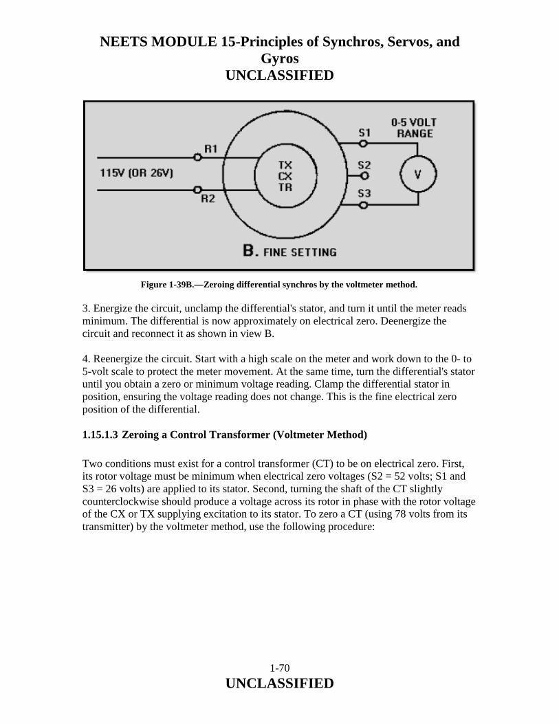
NEETS MODULE 15-Principles of Synchros, Servos, and Gyros
UNCLASSIFIED
1-70 UNCLASSIFIED
3. Energize the circuit, unclamp the differential's stator, and turn it until the meter reads minimum. The differential is now approximately on electrical zero. Deenergize the circuit and reconnect it as shown in view B. 4. Reenergize the circuit. Start with a high scale on the meter and work down to the 0- to 5-volt scale to protect the meter movement. At the same time, turn the differential's stator until you obtain a zero or minimum voltage reading. Clamp the differential stator in position, ensuring the voltage reading does not change. This is the fine electrical zero position of the differential. 1.15.1.3 Zeroing a Control Transformer (Voltmeter Method)
Two conditions must exist for a control transformer (CT) to be on electrical zero. First, its rotor voltage must be minimum when electrical zero voltages (S2 = 52 volts; S1 and S3 = 26 volts) are applied to its stator. Second, turning the shaft of the CT slightly counterclockwise should produce a voltage across its rotor in phase with the rotor voltage of the CX or TX supplying excitation to its stator. To zero a CT (using 78 volts from its transmitter) by the voltmeter method, use the following procedure:
Figure 1-39B.—Zeroing differential synchros by the voltmeter method.

NEETS MODULE 15-Principles of Synchros, Servos, and Gyros
UNCLASSIFIED
1-71 UNCLASSIFIED
1. Set the mechanism that drives the CT rotor to zero or to its reference position. Also, set the transmitter (CX or TX) that is connected to the CT to zero or its reference position. 2. Check to ensure there is zero volts between S1 and S3 and 78 volts between S2 and S3. If you cannot obtain these voltages, you will need to rezero the transmitter. NOTE: If you cannot use the 78 volts from the transmitter circuit and, an auto transformer is not available, you may use a 115- volt source. If you use 115 volts instead of 78 volts, do not energize the CT for more than 2 minutes because it will overheat and may become permanently damaged. 3. Deenergize the circuit and connect the circuit as shown in view A of figure 1-40. To obtain the 78 volts required to zero the CT, leave the S1 lead on, disconnect the S3 lead on the CT, and put the S2 lead (from the CX) on S3. This is necessary since 78 volts exists only between S1 and S2 or S2 and S3 on a properly zeroed CX. Now energize the circuit and turn the stator of the CT to obtain a minimum reading on the 250-volt scale. This is the coarse or approximate zero setting of the CT.
Figure 1-40A Zeroing a control transformer by the voltmeter method

NEETS MODULE 15-Principles of Synchros, Servos, and Gyros
UNCLASSIFIED
1-72 UNCLASSIFIED
4. Deenergize the circuit, reconnect the S1, S2, and S3 leads back to their original positions, and then connect the circuit as shown in view B. 5. Reenergize the circuit. Start with a high scale on the meter and work down to the 0- to 5-volts scale to protect the meter movement. At the same time, turn the stator of the CT to obtain a zero or minimum reading on the meter. Clamp down the CT stator, ensuring the reading does not change. This is the fine electrical zero position of the CT. 1.15.1.4 Zeroing Multispeed Synchro Systems
If multispeed synchro systems are used to accurately transmit data, the synchros within the systems must be zeroed together. This is necessary because these synchros require a common electrical zero to function properly in the system. First, establish the zero or reference position for the unit whose position the system transmits. Then, zero the most significant synchro in the system first, working down to the least significant. For example, zero the coarse synchro, then the medium synchro, and finally the fine synchro. When you zero those synchros, consider each synchro as an individual unit and zero it accordingly. Q-62. When is a synchro receiver (TR) properly zeroed?
Q-63. What should a voltmeter read when a TX is set on coarse zero?
Figure 1-40B.—Zeroing a control transformer by the voltmeter method

NEETS MODULE 15-Principles of Synchros, Servos, and Gyros
UNCLASSIFIED
1-73 UNCLASSIFIED
Q-64. What precaution should you take when you use 115 volts to zero a differential?
Q-65. Why should a synchro be rechecked for zero after it is clamped down?
Q-66. What is the output voltage of a CT when it is set on electrical zero?
Q-67. When you zero a multispeed synchro system which synchro should you zero first?
1.15.2 Electrical Lock Method
The electrical lock method, although not as accurate as the voltmeter method, is perhaps tile fastest method of zeroing synchros. However, this method can be used only if the rotors of the units to be zeroed are free to turn and the lead connections are accessible. For this reason, this method is usually used on the TR because, unlike transmitters, the TR shaft is free to turn. To zero a synchro by the electrical lock method, deenergize the unit, connect the leads as shown in figure 1-41, and apply power. The synchro rotor will then quickly snap to the electrical zero position and lock. If the indicating device connected to the synchro shaft does not point to zero, loosen the synchro in its mounting and rotate it until the zero position of the indicator corresponds with the electrical zero of the synchro. As we stated previously, you may use 115 volts as the power source instead of 78 volts, provided you do not leave the unit connected for more than 2 minutes.
Figure 1-41 Zeroing a synchro by the electrical lock method

NEETS MODULE 15-Principles of Synchros, Servos, and Gyros
UNCLASSIFIED
1-74 UNCLASSIFIED
1.15.2.1 SYNCHRO TESTERS
Two types of synchro testers are shown in figure 1-42, view (A) and view (B). Each is nothing more than a synchro receiver on which a calibrated dial is mounted.
Figure 1-42A Synchro Testers
Figure 1-42B.—Synchro Testers

NEETS MODULE 15-Principles of Synchros, Servos, and Gyros
UNCLASSIFIED
1-75 UNCLASSIFIED
These testers are used primarily for locating defective synchros. Although they do provide a method for zeroing synchros, they should not be relied on without question. It is possible for the calibrated dial to slip from its proper position, and since the dial is graduated only every 10º, it is difficult to read small angles with accuracy. Therefore, the synchro tester method of zeroing synchros is potentially less accurate than those previously described. To zero a TX, CX or TR using a synchro tester, use the following procedure: 1. Connect the synchro tester as shown in figure 1-43. 2. Set the unit whose position the TX or CX transmits accurately on zero or on its reference position. In the case of the TR, set its rotor to zero or to its reference position. 3. Turn the stator of the synchro being zeroed until the synchro tester dial reads 0º. The synchro is now approximately on electrically zero. 4. Momentarily short S1 to S3 as shown. If the synchro tester dial moves when S1 is shorted to S3, the synchro is not zeroed. Check the tester dial to ensure it has not slipped. If the tester dial has not slipped, move the synchro stator until there is no movement when S1 and S3 are shorted. This is the electrical zero position of the synchro being aligned. Q-68. What method of zeroing a synchro is perhaps the fastest but NOT necessarily the most accurate?
Figure 1-43 Zeroing a synchro using a synchro tester

NEETS MODULE 15-Principles of Synchros, Servos, and Gyros
UNCLASSIFIED
1-76 UNCLASSIFIED
Q-69. What restrictions are placed on the use of the electrical lock method?
Q-70. When you zero a synchro with a synchro tester, what is indicated by a jump in the synchro tester's dial when the S1 and S3 leads are momentarily shorted?
1.16 TROUBLESHOOTING SYNCHRO SYSTEMS
One of your duties in the Navy is to keep the synchro systems in your equipment in good working order. Therefore, it is essential that you become familiar with the details of synchro maintenance and repair. First, let's consider some of the more common problem areas you should avoid when working with synchros. As with any piece of electrical or electronic equipment, if it works—leave it alone. Do not attempt to zero a synchro system that is already zeroed just because you want to practice. More often than not, the system will end up more out of alignment than it was before you attempted to rezero it. Do not attempt to take a synchro apart, even if it is defective. A synchro is a piece of precision equipment that requires special equipment and techniques for disassembly. Disassembly should be done only by qualified technicians in authorized repair shops. A synchro, unlike an electric motor, does not require periodic lubrication. Therefore, never attempt to lubricate a synchro. Synchros also require careful handling. Never force a synchro into place, never use pliers on the threaded shaft, and never force a gear or dial onto the shaft. Finally, never connect equipment that is not related to the synchro system to the primary excitation bus. This will cause the system to show all the symptoms of a shorted rotor when the equipment is turned on; but, the system will check out good when the equipment is off. Trouble in a synchro system that has been in operation for some time is usually one of two types. First, the interconnecting synchro wiring often passes through a number of switches; at these points opens, shorts, or grounds may occur. You will be expected to trace down these troubles with an ohmmeter. You can find an open easily by checking for continuity between two points. Similarly, you can find a ground by checking the resistance between the suspected point and ground. A reading of zero ohms means that the point in question is grounded. Secondly, the synchro itself may become defective, due to opens and shorts in the windings, bad bearings, worn slip rings, or dirty brushes. You can do nothing about these defects except replace the synchro.

NEETS MODULE 15-Principles of Synchros, Servos, and Gyros
UNCLASSIFIED
1-77 UNCLASSIFIED
Troubles in new and modified synchro systems are most often because of (1) improper wiring and (2) misalignment caused by synchros not being zeroed. You are responsible for finding and correcting these troubles. You can check for improper wiring with an ohmmeter by making a point-to-point continuity and resistance check. You can correct misalignment of a synchro system by rezeroing the entire system. 1.16.1 TROUBLE INDICATORS
When trouble occurs in an electronic installation that contains a large number of synchro systems, it may be very difficult to isolate the trouble to one particular system. Since it is vital that maintenance personnel locate the point of trouble and fix it in as short a time as possible, indicators, which aid in locating the trouble quickly, are included in the equipment. These indicators are usually signal lights, mounted on a central control board and connected to the different synchro systems. When trouble occurs in a synchro system, the signal light connected to it may either light or flash. Maintenance personnel identify the defective system by reading the name or number adjacent to the light. Signal lights indicate either overload conditions or blown fuses. Overload indicators are usually placed in the stator circuit of a torque synchro system because the stator circuit gives a better indication of mechanical loading than does the current in the rotor circuit. One version of this type of indicator, as shown in figure 1-44, consists of a neon lamp connected across the stator leads of a synchro system by two transformers. The primaries, consisting of a few turns of heavy wire, are in series with two of the stator leads; the secondaries, consisting of many turns of fine wire, are in series with the lamp. The turns ratios are designed so that when excess current flows through the stator windings, the neon lamp lights. For example, when the difference in rotor positions exceeds about 18º, the lamp lights, indicating that the load on the motor shaft is excessive.
Figure 1-44 Overload stator current indicator

NEETS MODULE 15-Principles of Synchros, Servos, and Gyros
UNCLASSIFIED
1-78 UNCLASSIFIED
Blown fuse indicators are front panel lights which light when a protective fuse in series with the rotor blows. Figure 1-45 shows a typical blown fuse indicator. If excessive current flows in the rotor windings of this circuit because of a short or severe mechanical overload, one of the fuses will blow and the neon lamp across the fuse will light. Another type of blown fuse indicator uses a small transformer having two identical primaries and a secondary connected, as shown in figure 1-46. With both fuses closed, equal currents flow through the primaries. This induces mutually canceling voltages in the secondary. If a fuse blows, the induced voltage from just one primary is present in the secondary, and the lamp lights.
Figure 1-45 Simple blown fuse indicator
Figure 1-46 Blown fuse indicator requiring only one lamp

NEETS MODULE 15-Principles of Synchros, Servos, and Gyros
UNCLASSIFIED
1-79 UNCLASSIFIED
1.16.2 SYMPTOMS AND CAUSES
To help the technician further isolate synchro problems, many manufacturers furnish tables of trouble symptoms and probable causes with their equipment. These tables are a valuable aid in isolating trouble areas quickly. Tables 1-2 through 1-7 summarize, for a simple TX-TR system, some typical trouble symptoms and their probable causes. Keep in mind, if two or more receivers are connected to one transmitter, similar symptoms occur. However, if all the receivers act up, the trouble is usually in the transmitter or main bus. If the trouble appears in one receiver only, check the unit and its connections. The angles shown in these tables do not apply to systems using differentials, or to systems whose units are incorrectly zeroed. Preliminary Actions: Be sure TR is not jammed physically. Turn TX slowly in one direction and observe TR.
SYMPTOMS TROUBLE Overload Indicator lights Units hum at all TX settings One unit overheats TR follows smoothly but reads wrong
Rotor circuit open or shorted. See table 1-3.
Overload Indicator lights Units hum at all except two opposite TX settings Both units overheat TR stays on one reading half the time, then swings abruptly to the opposite one. TR may oscillate or spin.
Stator circuit shorted. See table 1-4.
Overload Indicator lights Units hum on two opposite TX settings Both units get warm TR turns smoothly on one direction, then reverses
Stator circuit open. See table 1-5.
TR reads wrong or turns backward, follows TX smoothly
Unit interconnections wrong. Unit not zeroed. See tables 1-6 and 1-7.
Table 1-2 General Symptoms
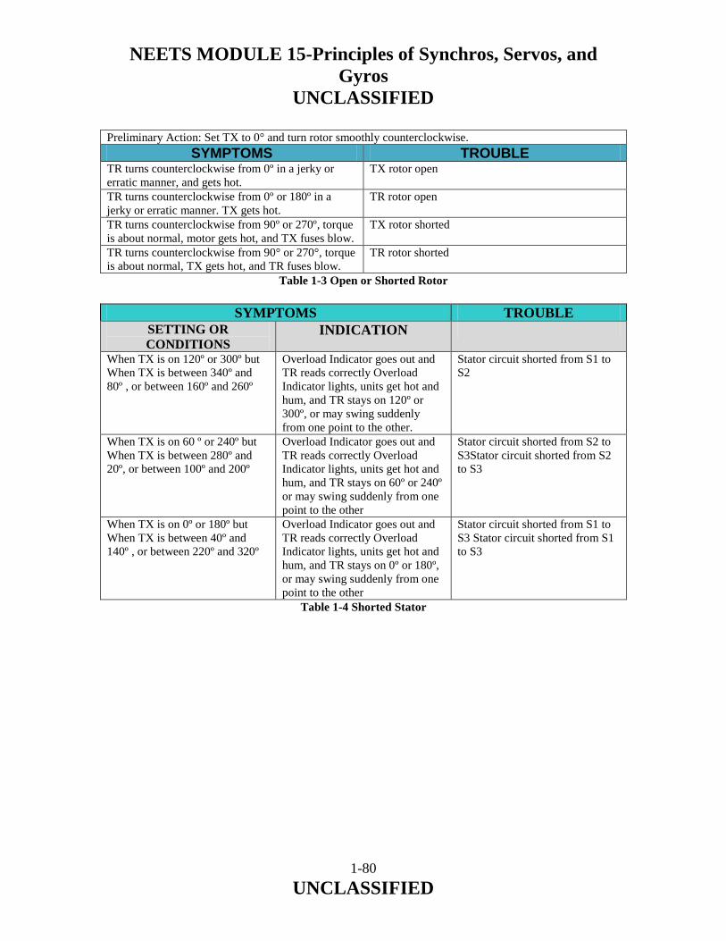
NEETS MODULE 15-Principles of Synchros, Servos, and Gyros
UNCLASSIFIED
1-80 UNCLASSIFIED
Preliminary Action: Set TX to 0° and turn rotor smoothly counterclockwise. SYMPTOMS TROUBLE
TR turns counterclockwise from 0º in a jerky or erratic manner, and gets hot.
TX rotor open
TR turns counterclockwise from 0º or 180º in a jerky or erratic manner. TX gets hot.
TR rotor open
TR turns counterclockwise from 90º or 270º, torque is about normal, motor gets hot, and TX fuses blow.
TX rotor shorted
TR turns counterclockwise from 90° or 270°, torque is about normal, TX gets hot, and TR fuses blow.
TR rotor shorted
Table 1-3 Open or Shorted Rotor
SYMPTOMS TROUBLE SETTING OR CONDITIONS
INDICATION
When TX is on 120º or 300º but When TX is between 340º and 80º , or between 160º and 260º
Overload Indicator goes out and TR reads correctly Overload Indicator lights, units get hot and hum, and TR stays on 120º or 300º, or may swing suddenly from one point to the other.
Stator circuit shorted from S1 to S2
When TX is on 60 º or 240º but When TX is between 280º and 20º, or between 100º and 200º
Overload Indicator goes out and TR reads correctly Overload Indicator lights, units get hot and hum, and TR stays on 60º or 240º or may swing suddenly from one point to the other
Stator circuit shorted from S2 to S3Stator circuit shorted from S2 to S3
When TX is on 0º or 180º but When TX is between 40º and 140º , or between 220º and 320º
Overload Indicator goes out and TR reads correctly Overload Indicator lights, units get hot and hum, and TR stays on 0º or 180º, or may swing suddenly from one point to the other
Stator circuit shorted from S1 to S3 Stator circuit shorted from S1 to S3
Table 1-4 Shorted Stator

NEETS MODULE 15-Principles of Synchros, Servos, and Gyros
UNCLASSIFIED
1-81 UNCLASSIFIED
SETTINGS OR CONDITIONS
INDICATION TROUBLE
When TX is on 150º or 330º and When TX is held on 0º
TR reverses or stalls and Overload Indicator lights TR moves between 300º and 0º in a jerky or erratic manner
S1 stator circuit open
When TX is on 90º or 270º and When TX is held on 0º
TR reverses or stalls and Overload Indicator lights TR moves to 0º or 180º , with fairly normal torque
S2 Stator circuit open
When TX is on 30º or 210º and When TX is held on 0º
TR reverses or stalls and Overload Indicator lights TR moves between 0º and 60º in a jerky or erratic manner
S3 stator circuit open
When TX is set at 0°, and then moved smoothly counterclockwise
Table 1-5 Open Stator
SETTING OR CONDITIONS
INDICATION TROUBLE
TX set to 0º and rotor turned smoothly counterclockwise
TR indication is wrong, turns clockwise from 240º
S1 and S2 stator connections are reversed
TR indication is wrong, turns clockwise from 120º
S2 and S3 stator connections are reversed
TR indication is wrong, turns clockwise from 0º
S1 and S3 stator connections are reversed
TR indication is wrong, turns counterclockwise from 120º
S1 is connected to S2, S2 is connected to S3, and S3 is connected to S1
TR indication is wrong, turns counterclockwise from 240º
S1 is connected to S3, S2 is connected to S1, and S3 is connected to S2
Table 1-6 Wrong Stator Connections, Rotor Wiring Correct

NEETS MODULE 15-Principles of Synchros, Servos, and Gyros
UNCLASSIFIED
1-82 UNCLASSIFIED
SETTINGS OR CONDITIONS
INDICATION TROUBLE
TX set to 0º and rotor turned smoothly counterclockwise
TR indication is wrong, turns counterclockwise from 180º
Stator connects are correct, but rotor connections are reversed
TR indication is wrong, turns clockwise from 60º
Stator connections S1 and S2 are reversed, and rotor connections are reversed
TR indication is wrong, turns clockwise from 300º
Stator connections S2 and S3 are reversed, and rotor connections are reversed
TR indication is wrong, turns clockwise from 180º
Stator connections S1 and S3 are reversed, and rotor connections are reversed
TR indication is wrong, turns counterclockwise from 300º
S1 is connected to S2, S2 is connected to S3, S3 is connected to S1, and rotor connections are reversed
TR indication is wrong, turns counterclockwise from 60º
S1 is connected to S3, S2 is connected to S1, S3 is connected to S2, and rotor connections are reversed
Table 1-7 Wrong Stator and/or Reversed Rotor Connections In a control system, the trouble may be slightly more difficult to isolate. However, the existence of trouble is readily indicated when the system does not properly respond to an input order. For control systems, it is easier to locate the trouble by using a synchro tester or by checking the operating voltages.

NEETS MODULE 15-Principles of Synchros, Servos, and Gyros
UNCLASSIFIED
1-83 UNCLASSIFIED
1.16.3 Voltage Testing
Another good way to isolate the trouble in an operating synchro system is to use known operating voltages as references for faulty operation. Since the proper operation of a system is indicated by specific rotor and stator voltages, an ac voltmeter can be used to locate the trouble. When an ac voltmeter is connected between any two stator leads, the voltage should vary from 0 to 90 volts (0 to 11.8 volts for 26- volt systems) as the transmitter rotates. The zero and maximum voltage values should occur at the following headings:
Meter Connected Between
Zero Voltage Headings
Maximum Voltage Headings
S1 and S2 120º, 300º 30º, 210º S2 and S3 60º, 240º 150º, 330º S1 and S3 0°, 180° 90°, 270° The rotor voltage should remain constant at all times, either 115 volts or 26 volts. In a system where the units are close enough to permit checking, the voltage between the R1 and R2 terminal of any unit energized by the primary ac source and the corresponding R1 or R2 terminal of any other unit energized by the primary ac source should be zero. When the excitation voltage (115 volts or 26 volts) is above or below the nominal value, the maximum stator voltages will also be above or below normal. 1.16.4 SYNCHRO TESTERS
Synchro testers, as stated earlier, are used primarily for quickly locating a defective synchro. These testers are capable of functioning as either transmitter or receiver. When a transmitter is suspected of being defective, a synchro tester is usually substituted in its place to simulate its actions. When the tester is used in this manner, a braking arrangement on the tester applies the necessary friction to hold its shaft in different positions so you can determine whether the transmitter is good or bad. When using the tester as a transmitter, it is usually a good idea to use only one receiver so as not to overload the tester. If the tester is connected in place of a TR or used to check the output of a transmitter, the brake is released, allowing the rotor to turn and indicate the transmitter's position. By observing the tester's response to the transmitted signal, you can determine if the TR is defective or if the transmitter's output is incorrect.

NEETS MODULE 15-Principles of Synchros, Servos, and Gyros
UNCLASSIFIED
1-84 UNCLASSIFIED
Q-71. What should you do with a synchro that has a bad set of bearings?
Q-72. Name two types of trouble you would expect to find in a newly installed synchro system.
Q-73. What type of indicator is usually placed in the stator circuit of a torque synchro system?
Q-74. What is the most probable cause of trouble in a synchro system that has all of its receivers reading incorrectly?
Q-75. If an ac voltmeter is connected between the S2 and S3 windings on a TX, at what two rotor positions should the voltmeter read maximum voltage?
Q-76. What precaution should you take when substituting a synchro tester in a circuit for a transmitter?
You should now have a good working knowledge of synchro systems. For further study and assistance in applying this knowledge to synchro troubleshooting and alignment, consult the following references: Pertinent PMS sources: 1. Applicable maintenance instruction manuals. 2. Military Handbook, Synchros, Description and Operation, MIL-HDBK-225A (March 91).
NEETS MODULE 15-Principles of Synchros, Servos, and Gyros
UNCLASSIFIED
1-85 UNCLASSIFIED
1.17 SUMMARY
Now that you have completed this chapter, a short review is in order. The following review will refresh your memory of synchros, their principles of operation, and how they are tied together to form synchro systems. A SYNCHRO resembles a small electric motor in size and appearance and operates like a variable transformer. Synchros are used primarily for the rapid and accurate transmission of data. They are also used as control devices in servo systems. A SYNCHRO SYSTEM consists of two or more synchros interconnected electrically. TORQUE SYNCHRO SYSTEMS are systems that use torque synchros to move light loads, such as dials and pointers. CONTROL SYNCHRO SYSTEMS are systems that use control synchros to control servo systems. The servo system, in conjunction with the control synchro system, is used to move heavy loads such as gun directors, radar antennas, and missile launchers. MILITARY STANDARD SYNCHROS are synchros that conform to specifications that are uniform throughout the Armed Services. They replace the prestandard Navy synchros. A typical example of a military standard synchro designation code is 18TR6A. This code has the following interpretation: 18—Synchro diameter of 1.71 to 1.80 inches T—Torque R—Receiver 6—60-Hz frequency A—Original design

NEETS MODULE 15-Principles of Synchros, Servos, and Gyros
UNCLASSIFIED
1-86 UNCLASSIFIED
PRESTANDARD NAVY SYNCHROS are synchros designed to meet Navy, rather than servicewide, specifications. A typical example of a prestandard Navy synchro designation code is 5DG. This code has the following interpretation: 5—Synchro diameter of 3 3/8 to 3 5/8 inches, length 1/2 inches, weight 5 lbs. DG—Differential transmitter SCHEMATIC SYMBOLS for synchros are drawn in two different forms. Two of the five standard military symbols are drawn to show only the external connections to the synchro. The other three symbols are drawn to show both the external connections and the internal relationship between the rotor and the stator. SYNCHROS ARE CONSTRUCTED like motors. Each contains a rotor, similar in appearance to the armature in a motor, and a stator which corresponds to the field in a motor. A SYNCHRO ROTOR is composed of either a single coil of wire wound on a laminated core or a group of coils wound in slots in a laminated core. The laminated core is rigidly mounted on a shaft that is free to turn inside the stator. Two slip rings are mounted on one end of the shaft to supply excitation voltage to the rotor. There are two common types of synchro rotors - the salient-pole rotor and the drum or wound rotor. The SALIENT-POLE ROTOR has a single coil of wire wound on a laminated core, shaped like a dumbbell or the letter "H." This type of rotor is frequently used in transmitters and receivers. The DRUM OR WOUND ROTOR may be wound continuously with a single length of wire or may have a group of coils connected in series. This type of rotor is used in most synchro control transformers and differential units, and occasionally in torque transmitters. When used in differential units, the rotor is wound with three coils so their magnetic axes are 120 degrees apart. A SYNCHRO STATOR is a cylindrical structure of slotted lamination on which three Y-connected coils are wound with their axes 120º apart. TORQUE is simply a measure of how much load a machine can turn. In heavy machinery, it is expressed in pound-feet and in torque synchro systems, it is expressed in ounce-inches.

NEETS MODULE 15-Principles of Synchros, Servos, and Gyros
UNCLASSIFIED
1-87 UNCLASSIFIED
SYNCHRO OPERATING VOLTAGES AND FREQUENCIES vary with different equipment. Synchros are designed for use on either a 115-volt or a 26-volt power source. They also operate on either a 60- or 400-Hz frequency. ELECTROMAGNETIC THEORY forms the basis for understanding all synchro operations. The RESULTANT MAGNETIC FIELD in a synchro is the result of the combined effects of three stator fields spaced 120º apart. The stator coil with the strongest field has the greatest effect on the position of the resultant field. The ZERO-DEGREE POSITION of a synchro, transmitter is the position where the rotor and the S2 stator winding are parallel. The SYNCHRO TRANSMITTER (TX) converts a mechanical input, which is the angular position of the rotor, into an electrical output signal. The output is taken from the stator windings and is used by a TDX, a TDR, or a TR to move light loads, such as dials and pointers. MAXIMUM INDUCED STATOR VOLTAGE occurs in a single synchro stator coil each time there is maximum magnetic coupling between the rotor and the stator coil. This voltage is approximately equal to the product of the effective voltage on the primary, the secondary-to-primary turns ratio, and the magnetic coupling between the rotor and the stator coil. The SYNCHRO RECEIVER (TR) is electrically identical to the synchro transmitter. The receiver, however, uses some form of rotor damping that is not present in the transmitter. This real difference between a synchro transmitter and a synchro receiver lies in their applications. The receiver converts the electrical data, supplied to its stator from the transmitter, back to a mechanical angular output through the movement of its rotor. DAMPING is a method used in synchro receivers to prevent the rotor from oscillating or spinning. There are two types of damping methods - ELECTRICAL and MECHANICAL. The electrical method is commonly used in small synchros, while the mechanical method is more effective in larger synchros. A TORQUE SYNCHRO SYSTEM consists of a torque transmitter (TX) electrically connected to a torque receiver (TR). In this system, the mechanical input to the TX is transmitted electrically to the TR. The TR reproduces the signal from the TX and positions either a dial or a pointer to indicate the transmitted information.

NEETS MODULE 15-Principles of Synchros, Servos, and Gyros
UNCLASSIFIED
1-88 UNCLASSIFIED
CORRESPONDENCE is the term given to the positions of the rotors of a synchro transmitter and a synchro receiver when both rotors are on 0º or displaced from 0º by the same angle. SIGNAL is defined as the angle through which a transmitter rotor is mechanically turned. This term has the same meaning as "transmitter's mechanical input." RECEIVER ROTATION may be in a direction opposite to that desired. When it is necessary to reverse receiver rotation, reverse the S1 and S3 connections on either the synchro transmitter or the synchro receiver. The causes both synchro rotors to turn through the same angle but in opposite directions. REVERSED ROTOR CONNECTIONS are common problems in new or modified synchro systems and should not be confused with the deliberate reversal of the stator connections. The reversal of the R1 and R2 connections on a synchro rotor causes a 180º error between the synchro transmitter and the synchro receiver, but the direction of rotor rotation still remains the same. A TORQUE DIFFERENTIAL SYNCHRO SYSTEM consists either of a TX, a TDX, (torque differential transmitter), and a TR; or two TXs and one TDR (torque differential receiver). The system is used in applications where it is necessary to compare two signals, add or subtract the signals, and finish an output proportional to the sum of or difference between the two signals. The TORQUE DIFFERENTIAL TRANSMITTER (TDX) has one electrical input to the stator and one mechanical input to the rotor. The TDX either adds or subtracts these inputs, depending upon how it is connected in the system, and provides an electrical output from its rotor proportional to the sum of or difference between the two signals. The TORQUE DIFFERENTIAL RECEIVER (TDR) is electrically identical to the TDX. The only difference in their construction is that the TDR has some form of damping. The real difference between the two differentials lies in their applications. The TDR has two electrical inputs, one to the rotor and the other to the stator. The output is the mechanical position of the rotor. As is the case with the TDX, the addition or subtraction function of the TDR depends upon how it is connected in the system. The TX-TDX-TR SYSTEM performs subtraction when the system contains standard synchro connections. Addition can also be performed with this system by reversing the S1 and S3 leads between the TX and the TDX, and the R1 and R3 leads between the TDX and the TR. Remember, this system works like a basic synchro system when the rotor of the TDX is on 0º; in this condition the TR rotor follows the TX rotor exactly.

NEETS MODULE 15-Principles of Synchros, Servos, and Gyros
UNCLASSIFIED
1-89 UNCLASSIFIED
The TX-TDR-TX SYSTEM performs subtraction when the system contains standard synchro connections. Addition can also be performed with this system when the R1 and R3 leads between the TDR rotor and TX No. 2 are reversed. CONTROL SYNCHRO SYSTEMS contain control synchros and are used to control large amounts of power with a high degree of accuracy. These synchro systems control servos that generate the required power to move heavy loads. CONTROL SYNCHROS are of three different types: the control transmitter (CX), the control transformer (CT), and the control differential transmitter (CDX). The CX and the CDX are identical to the TX and the TDX except for higher impedance windings. In theory, the CX and CDX are the same as the TX and TDX, respectively. The CONTROL TRANSFORMER (CT) is a synchro device that compares two signals, the electrical signal applied to its stator, and the mechanical signal applied to its rotor. The output is an electrical voltage, which is taken from the rotor winding and used to control some form of power amplifying device. The phase and amplitude of the output voltage depend on the angular position of the rotor with respect to the magnetic field of the stator. ERROR SIGNAL is the name given to the electrical output of a CT. The reason is that the electrical output voltage represents the amount and direction that the CX and CT rotors are out of correspondence. It is this error signal that eventually is used in moving the load in a typical servo system. The SYNCHRO CAPACITOR is a unit containing three delta-connected capacitors. It is used in synchro systems containing either differential transmitters or CTs. The addition of the synchro capacitor to these systems greatly reduces the stator current and therefore increases the accuracy of the systems. The SPEED OF DATA TRANSMISSION is simply the number of times a synchro transmitter rotor must turn to transmit a full range of values. You refer to the speed of data transmission as being 1-speed, 2-speed, 36-speed, or some other definite numerical ratio. MULTISPEED SYNCHRO SYSTEMS transmit a wide range of data at different speeds and still maintain a high degree of accuracy. To indicate the number of different speeds at which data is transmitted, refer to the system as being a single-speed, dual-speed, or tri-speed synchro system.

NEETS MODULE 15-Principles of Synchros, Servos, and Gyros
UNCLASSIFIED
1-90 UNCLASSIFIED
A DOUBLE RECEIVER consists of a fine and a coarse receiver enclosed in a common housing. It has a two-shaft output (one inside the other), and its operation may be likened to the hour and minute hands of a clock. STICKOFF VOLTAGE is a low voltage used in multispeed synchro systems that contain CTs to prevent false synchronizations. The voltage is usually obtained from a small transformer and applied across the rotor terminals of the coarse CT. ELECTRICAL ZERO is the reference point for alignment of all synchro units. SYNCHRO ZEROING METHODS are various and depend upon the facilities and tools available, and how the synchros are connected in the system. Some of the more common zeroing methods are the voltmeter, the electric-lock, and the synchro-tester methods. The VOLTMETER ZEROING METHOD is the most accurate and requires a precision voltmeter. This method has two major steps-the coarse or approximate setting and the fine setting. The coarse setting ensures the synchro is not zeroed 180º away from its reference. This setting may be approximated physically by aligning two marks on the synchro. The fine setting is where the synchro is precisely set on 0º . ELECTRICAL-LOCK ZEROING METHOD is perhaps the fastest. However, this method can be used only if the rotors of the synchros are free to turn and the leads are accessible. For this reason, this method is usually used on TRs. The SYNCHRO-TESTER ZEROING METHOD is potentially less accurate than the voltmeter or electric lock methods. This is because the dial on the tester is difficult to read and may slip from its locked position. The synchro tester is nothing more than a synchro receiver on which a calibrated dial is mounted. The tester is used primarily for locating defective synchros but does provide a method for zeroing synchros. TROUBLE INDICATORS are signal lights used to aid maintenance personnel in locating synchro trouble quickly. These lights are usually mounted on a central control board and connected to different synchro systems. The lights indicate either overload conditions or blown fuses.

NEETS MODULE 15-Principles of Synchros, Servos, and Gyros
UNCLASSIFIED
1-91 UNCLASSIFIED
SYNCHRO TROUBLESHOOTING is the locating or diagnosing of synchro malfunctions or breakdown by means of systematic checking or analysis. This is done by using trouble indicators, trouble tables furnished by manufacturers, known operating voltages as references, and synchro testers.

NEETS MODULE 15-Principles of Synchros, Servos, and Gyros
UNCLASSIFIED
1-92 UNCLASSIFIED
ANSWERS TO QUESTIONS Q1. THROUGH Q76.
A-1. The synchro. A-2. Precise and rapid transmission of data between equipment and stations. A-3. Torque and control. A-4. A torque synchro is used for light loads and a control synchro is used in systems
desired to move heavy loads.
A-5. The torque receiver (TR) and the torque differential receiver (TDR). A-6. It is the third modification of a 26-volt 400-hertz (torque) synchro transmitter
whose body diameter is between 1.01 and 1.10 inches. A-7. The Navy prestandard designation code. A-8. The position of the arrow. A-9. The rotor and the stator. A-10. The drum or wound rotor. A-11. By the magnetic coupling from the rotor. A-12. At the terminal board. A-13. The number and type of synchro receivers, the mechanical loads on these
receivers and the operating temperatures of both the transmitter and receivers. A-14. A measure of how much load a machine can turn. A-15. Ounce-inches. A-16. Aircraft.

NEETS MODULE 15-Principles of Synchros, Servos, and Gyros
UNCLASSIFIED
1-93 UNCLASSIFIED
A-17. When it is overloaded. A-18. Synchros have one primary winding that can be turned through 360º and three
secondary windings spaced 120º apart. A-19. The transmitter is in its zero-position when the rotor is aligned with the S2 stator
winding. A-20. When the rotor coil is aligned with the stator coil. A-21. The amplitude of the primary voltage, the turns ratio, and the angular
displacement between the rotor and the stator winding. A-22. A synchro receiver uses some form of damping to retard excessive oscillations or
spinning. A-23. Mechanical damping. A-24. A synchro transmitter and a synchro receiver. A-25. The rotor leads. A-26. The voltages are equal and oppose each other. A-27. Signal. A-28. 1 and S3. A-29. The rotor leads on either the transmitter or the receiver are reversed. A-30. Differential synchros can handle more signals than regular synchros and also
perform addition and subtraction functions. A-31. The TDX and the TDR. A-32. Their application: a TDX has one electrical and one mechanical input with an
electrical output.
NEETS MODULE 15-Principles of Synchros, Servos, and Gyros
UNCLASSIFIED
1-94 UNCLASSIFIED
A-33. The way the differential synchro is connected in a system is the deciding factor on whether the unit adds or subtracts its inputs.
A-34. When the TDX rotor is on 0º. A-35. 240º. A-36. 80º. A-37. The S1 and S3 leads are reversed between the TX and the TDX, and the R1 and
R3 leads are reversed between the TDX rotor and the TR. A-38. The R1 and R3 leads between the TDR rotor and the TX to which it is connected. A-39. Clockwise. A-40. A control synchro. A-41. CX, CT, and CDX. A-42. The CX and CDX have higher impedance windings. A-43. The rotor is specially wound, it is never connected to an ac supply, and its output
is always applied to a high-impedance load. A-44. They are perpendicular to each other. A-45. The voltage is maximum and in phase with the ac excitation voltage to the CX. A-46. Error signal. A-47. When the CX and CT rotors are in correspondence. A-48. To improve overall synchro system accuracy by reducing stator currents. A-49. TDXs, CDXs, and Cts. A-50. Magnetizing current.

NEETS MODULE 15-Principles of Synchros, Servos, and Gyros
UNCLASSIFIED
1-95 UNCLASSIFIED
A-51. They are delta-connected across the stator windings. A-52. To keep the connections as short as possible in order to maintain system. A-53. A dual or double-speed synchro system. A-54. Greater accuracy without the loss of self-synchronous operation. A-55. The gear ratio between the two transmitters. A-56. A tri-speed synchro system. A-57. If one of the receivers goes bad the entire unit must be replaced. A-58. It is used in synchro systems to prevent false synchronizations. A-59. Electrical zero. A-60. The voltmeter method. A-61. A61.It ensures the synchro is on 0º, not 180º. A-62. A TR is zeroed when electrical zero voltages exist across its stator windings at the
same time its rotor is on zero or on its mechanical reference position. A-63. Approximately 37 volts. A-64. Never leave the circuit energized for more than 2 minutes. A-65. To ensure that it did not move off zero while it was being clamped. A-66. Zero or minimum voltage. A-67. The coarse synchro. A-68. The electrical lock method. A-69. It can be used only if the leads of the synchro are accessible and the rotor is free
to turn.

NEETS MODULE 15-Principles of Synchros, Servos, and Gyros
UNCLASSIFIED
1-96 UNCLASSIFIED
A-70. The synchro under test is not on electrical zero. A-71. Replace it. A-72. Improper wiring and misalignment. A-73. An overload indicator. A-74. The transmitter or main bus. A-75. 150º and 330º A-76. Use only one receiver so as not to overload the tester.

NEETS MODULE 15-Principles of Synchros, Servos, and Gyros
UNCLASSIFIED
2-1 UNCLASSIFIED
2 SERVOS
LEARNING OBJECTIVES
After you finish this chapter, you should be able to do the following: 1. Define the term "servo system" and the terms associated with servo systems,
including open-loop and closed-loop control systems. 2. Identify from schematics and block diagrams the various servo circuits; give short
explanations of the components and their characteristics; and of each circuit and its characteristics.
3. Trace the flow of data through the components of typical servo systems from input(s) to b outputs(s) (cause to effect).
2.1 SERVOS
Servo mechanisms, also called SERVO SYSTEMS or SERVOS for short, have countless applications in the operation of electrical and electronic equipment. In working with radar and antennas, directors, computing devices, ship's communications, aircraft control, and many other equipments it is often necessary to operate a mechanical load that is remote from its source of control. To obtain smooth, continuous, and accurate operation, these loads are normally best controlled by synchros. As you already know, the big problem here is that synchros are not powerful enough to do any great amount of work. This is where servos come into use. A servo system uses a weak control signal to move large loads to a desired position with great accuracy. The key words in this definition are move and great accuracy. Servos may be found in such varied applications as moving the rudder and elevators of a model airplane in radio-controlled flight, to controlling the diving planes and rudders of nuclear submarines. Servos are powerful. They can move heavy loads and be remotely controlled with great precision by synchro devices. They take many forms. Servo systems are either electromechanical, electrohydraulic, hydraulic, or pneumatic. Whatever the form, a relatively weak signal that represents a desired movement of the load is generated, controlled, amplified, and fed to a servo motor that does the work of moving the heavy load.

NEETS MODULE 15-Principles of Synchros, Servos, and Gyros
UNCLASSIFIED
2-2 UNCLASSIFIED
Q-1. What is a servo?
2.2 CATEGORIES OF CONTROL SYSTEMS
A control system is a group of components that are linked together to perform a specific purpose. Generally, a control system has a large power gain between input and output. The components used in the system and the complexity of the system are directly related to the requirements of the system's application. Control systems are broadly classified as either CLOSED-LOOP or OPEN-LOOP. Closed-loop control systems are the type most commonly used in the Navy because they respond and move the loads they are controlling quicker and with greater accuracy than open-loop systems. The reason for quicker response and greater accuracy is that an automatic feedback system informs the input that the desired movement has taken place. Upon receipt of this feedback information, the system stops the motor, and motion of the load ceases until another movement is ordered by the input. This is similar to the system that controls heat in many homes. The thermostat (input) calls for heat. The furnace (output) produces heat and distributes it. Some of the heat is "fed back" to the thermostat. When this "feedback" raises the temperature of the room to that of the thermostat setting, the thermostat responds by shutting the system down until heat is again required. In such a system, the feedback path, input to output and back to input, forms what is called a "closed loop." This is a term you will hear and use often in discussions of control systems. Because closed-loop control systems are automatic in nature, they are further classified by the function they serve (e.g., controlling the position, the velocity, or the acceleration of the load being driven). An open-loop control system is controlled directly, and only, by an input signal, without the benefit of feedback. The basic units of this system are an amplifier and a motor. The amplifier receives a low-level input signal and amplifies it enough to drive the motor to perform the desired job. Open-loop control systems are not as commonly used as closed-loop control systems because they are less accurate.

NEETS MODULE 15-Principles of Synchros, Servos, and Gyros
UNCLASSIFIED
2-3 UNCLASSIFIED
2.2.1 Open-Loop Control System
As we stated previously, an open-loop control system is controlled directly, and only, by an input signal. The basic units of this type consist only of an amplifier and a motor. The amplifier receives a low-level input signal and amplifies it enough to drive the motor to perform the desired job. The open-loop control system is shown in basic block diagram form in figure 2-1. With this system, the input is a signal that is fed to the amplifier. The output of the amplifier is proportional to the amplitude of the input signal. The phase (ac system) and polarity (dc system) of the input signal determines the direction that the motor shaft will turn. After amplification, the input signal is fed to the motor, which moves the output shaft (load) in the direction that corresponds with the input signal. The motor will not stop driving the output shaft until the input signal is reduced to zero or removed. This system usually requires an operator who controls speed and direction of movement of the output by varying the input. The operator could be controlling the input by either a mechanical or an electrical linkage. 2.2.2 THE CLOSED-LOOP CONTROL SYSTEM
A closed-loop control system is another name for a servo system. To be classified as a servo, a control system must be capable of the following: 1. Accepting an order that defines the desired result 2. Determining the present conditions by some method of feedback 3. Comparing the desired result with the present conditions and obtaining a difference or an error signal 4. Issuing a correcting order (the error signal) that will properly change the existing conditions to the desired result 5. Obeying the correcting order
Figure 2-1 Open-loop control system basic block diagram

NEETS MODULE 15-Principles of Synchros, Servos, and Gyros
UNCLASSIFIED
2-4 UNCLASSIFIED
We have discussed the open- and closed-loop control systems and defined a servo system as a closed-loop control system. Although not technically accurate by definition, open-loop control systems are also often referred to in the Navy and many publications as servo systems even though they lack one of the five basic requirements, that of feedback. Q-2. In an open-loop control system, what action reduces the input to zero so the load is stopped at the desired position?
Q-3. What basic requirement of a closed-loop system (not present in open-loops) enables present load position to be sensed?
2.3 OPERATION OF A BASIC SERVO SYSTEM
For the following discussion of a servo system, refer to figure 2-2, view (A), view (B), view (C) and view (D).This closed-loop servo system is the most common type in the Navy today. It is normally made up of electromechanical parts and consists basically of a synchro-control system, servo amplifier, servo motor, and some form of feedback (response).
Figure 2-2A A basic servo system (closed-loop)

NEETS MODULE 15-Principles of Synchros, Servos, and Gyros
UNCLASSIFIED
2-5 UNCLASSIFIED
The synchro-control system provides a means of controlling the movement of the load, which may be located in a remote space. The servo amplifier and servo motor are the parts of the system in which power is actually developed (to move the load). As you remember, the controlling signal from a CT is relatively weak, too weak to drive an electric motor directly. In views A through D of figure 2-2, assume that the control signal will be initiated by a handcrank input connected to the synchro transmitter (CX). The dials located on the CX and the CT indicate the positions of the synchro's rotors, while the dial on the load indicates the position of the load.
Figure 2-2B.—A basic servo system (closed-loop)
Figure 2-2C.—A basic servo system (closed-loop)
Figure 2-2D.—A basic servo system (closed-loop)

NEETS MODULE 15-Principles of Synchros, Servos, and Gyros
UNCLASSIFIED
2-6 UNCLASSIFIED
In view A, the dials of both the CX and the load indicate that the load is in the desired position. Because the load is where it should be, there will be no error signal present at the servo amplifier and no power to the servo motor. In view B, the rotor of the CX has been moved by the handcrank to 90º. (This indicates that it is ordered to move the load by 90º.) Notice that the rotor of the CT is still at 0º. The CT now develops a signal, called the ERROR SIGNAL, which is proportional in amplitude to the amount the CT rotor is out of correspondence with the CX rotor. The phase of the error signal indicates the direction the CT rotor must move to reduce the error signal to zero or to "null out." The error signal is sent to the servo amplifier. In view C, the error signal has been amplified by the servo amplifier and sent on to the servo motor. The motor starts to drive in the direction that will reduce the error signal and bring the CT rotor back to the point of correspondence. In this case the motor is turning clockwise. The mechanical linkage attached to the servo motor also moves the rotor of the CT. This feedback causes the amplitude of the error signal to decrease, slowing the speed at which the load is moving. In view D, the servo motor has driven both the load and the rotor of the CT, so that the CT is now in correspondence with the CX rotor. As a result, the error signal is reduced to zero (nulled). The load stops at its new position. Note that in this servo system, we moved a heavy load to a predetermined position through the simple turning of a handcrank. In responding to the handcrank, the servo system performed a basic positioning function. Two key points for you to remember, thus far, about the operation of the closed-loop servo system are: 1. The original error (movement of the CX rotor) was "detected" by the CT. For this reason the CT is called an ERROR DETECTOR. 2. The servo motor, in addition to moving the load, also provides mechanical feedback to the CT to reduce the error signal. For this reason the servo motor is also called an ERROR REDUCER.

NEETS MODULE 15-Principles of Synchros, Servos, and Gyros
UNCLASSIFIED
2-7 UNCLASSIFIED
Q-4. An error signal is the difference between what two quantities fed to the CT (error detector)?
Q-5. What are the two functions of the servo motor in the system shown in figure 2-2?
2.3.1 Functional Servo Loops
Servo systems are also classified according to their functions: POSITION, VELOCITY, and ACCELERATION. We will cover the most common, POSITION and VELOCITY, in detail. 2.3.1.1 The Position Servo Loop
The primary purpose of the POSITION SERVO is to control the position of the load it is driving. It can be used to position a great number of devices (for example, valves, control surfaces, weapons, etc.). The basic servo loop we just explained using the block diagram in figure 2-2 is that of an ac position servo system. In the ac position servo system, the amplitude and phase of the ac error signal determine the amount and direction the load will be driven. In a dc position servo system, the amplitude and polarity of a dc error signal respectively are used to determine the amount and direction the load will be driven. Figure 2-3, view A, is a block diagram of a closed-loop de position servo. Note the Greek letter Sigma (Σ), meaning summation, surrounded by a circle.
Figure 2-3A Block diagram of a position servo

NEETS MODULE 15-Principles of Synchros, Servos, and Gyros
UNCLASSIFIED
2-8 UNCLASSIFIED
This is the summation, or "sum point" where the input signal, and the response signal (feedback) are summed to produce the error signal. View B shows a more in-depth illustration of view A. With the wiper arms of R1 and R4 at the midpoint of travel, the voltage from the wiper arm to ground is zero volts. Therefore, zero volts would also be measured at the connection point between R2 and R3 (the summation point). This means that the error signal is zero. With no input signal, the amplifier output is zero; therefore, the motor shaft remains stationary. For the purpose of explanation, imagine that the R1 wiper arm is mechanically moved upward to a new position where a voltage between the wiper arm and ground measures +10 volts. Further measurement shows zero volts between the wiper arm of R4 and ground. Since R 2 and R3 are of equal values, +5 volts is measured between the sum point and ground because 5 volts is dropped across each resistor. The +5 volts at the sum point is the "error" signal. As shown in figure 2-4, (view A, view B, and view C), when no error is present, the voltage at the sum point is zero. This is because the network composed of R1, R2, R 3, and R4 is balanced. When the wiper of R 1 is moved toward +45 volts, the network becomes unbalanced as shown in view B. The left-hand side of R 2 becomes positive. This causes current to flow from +45 volts through R3 and R2 to the +10 volts at the left side of R2. Because R2 and R3 are of equal value, the voltage drops then will be equal; therefore, the voltage at the sum point will equal +5 volts.
Figure 2-3B.—Block diagram of a position servo

NEETS MODULE 15-Principles of Synchros, Servos, and Gyros
UNCLASSIFIED
2-9 UNCLASSIFIED
Figure 2-4A Development of the error signal
Figure 2-4B.—Development of the error signal

NEETS MODULE 15-Principles of Synchros, Servos, and Gyros
UNCLASSIFIED
2-10 UNCLASSIFIED
The +5 volt error signal is fed into the amplifier. The amplified output starts driving the motor. The mechanical feedback from the motor drives the R4 wiper arm down when the R1 wiper is moved up, as shown in view C. This causes the right-hand side of R3 to go negative. When the R 4 wiper travels far enough toward negative, it causes the right-hand side of R3 to equal the voltage, but of opposite polarity, of the left-hand side of R2. Simply stated, the voltage at the sum point will be zero again, and the motor will stop. This is true because R2 and R 3 are of equal ohmic value, and when the left-hand side equals +10 volts, the right-hand side equals -10 volts. The point between the two resistors becomes zero volts at this time. At the instant that this occurs, the output shaft will have positioned the load to the new position. Figure 2-5 shows the basic operation of a typical position servo having wide application in Navy equipment. Remember that in a position servo, an input order indicates a position in which a load is to be placed. The load in figure 2-5 is a gun turret. The purpose of the system is to position the gun by means of an order from a remote handcrank. The load is mechanically coupled through a gear train to the rotor of a CT so that the turret's position is always accurately represented by the position of the CT's rotor. An order signaling the desired position of the gun turret is fed into the servo by positioning the rotor of the CX with the handcrank. A corresponding signal immediately appears across the CT stator. This signal differs from the actual position of the gun turret, causing an error voltage to be developed across the CT rotor. The error voltage is fed from the CT rotor to the servo amplifier. At this point it is converted into power with a polarity or phase relationship that drives the motor in the direction necessary to bring the load into the desired position.
Figure 2-4C.—Development of the error signal
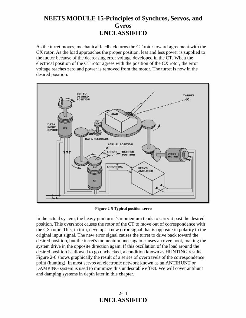
NEETS MODULE 15-Principles of Synchros, Servos, and Gyros
UNCLASSIFIED
2-11 UNCLASSIFIED
As the turret moves, mechanical feedback turns the CT rotor toward agreement with the CX rotor. As the load approaches the proper position, less and less power is supplied to the motor because of the decreasing error voltage developed in the CT. When the electrical position of the CT rotor agrees with the position of the CX rotor, the error voltage reaches zero and power is removed from the motor. The turret is now in the desired position. In the actual system, the heavy gun turret's momentum tends to carry it past the desired position. This overshoot causes the rotor of the CT to move out of correspondence with the CX rotor. This, in turn, develops a new error signal that is opposite in polarity to the original input signal. The new error signal causes the turret to drive back toward the desired position, but the turret's momentum once again causes an overshoot, making the system drive in the opposite direction again. If this oscillation of the load around the desired position is allowed to go unchecked, a condition known as HUNTING results. Figure 2-6 shows graphically the result of a series of overtravels of the correspondence point (hunting). In most servos an electronic network known as an ANTIHUNT or DAMPING system is used to minimize this undesirable effect. We will cover antihunt and damping systems in depth later in this chapter.
Figure 2-5 Typical position servo

NEETS MODULE 15-Principles of Synchros, Servos, and Gyros
UNCLASSIFIED
2-12 UNCLASSIFIED
Q-6. What are the three relatively common classifications of servo systems by function?
Q-7. The output of the sum point must contain information that controls what two factors of load movement in a position servo?
Q-8. What term is used for a series of overshoots in a servo system?
Figure 2-6 Overtravels of the correspondence point (hunting)

NEETS MODULE 15-Principles of Synchros, Servos, and Gyros
UNCLASSIFIED
2-13 UNCLASSIFIED
2.3.1.2 Velocity Servo Loop
The VELOCITY SERVO is based on the same principle of error-signal generation as the position servo, but there are some operational differences. Two major differences are as follows: 1. In this loop the VELOCITY of the output is sensed rather than the position of the load. 2. When the velocity loop is at correspondence or null position, an error signal is still present and the load is moving. This type of servo is used in applications where the load is required to be driven at a constant speed. This speed is governed by the level of the error signal present. Radar antennas, star-tracking telescopes, machine cutting tools, and other devices requiring variable speed regulation are all examples of the types of load this servo may be used to drive. Figure 2-7 is a block diagram of a velocity servo. It is similar to the block diagram of the position servo loop except that the velocity servo loop contains a TACHOMETER in the feedback line. The tachometer (tach) is a small generator that generates a voltage proportional to its shaft speed.
Figure 2-7 Block diagram of a velocity servo

NEETS MODULE 15-Principles of Synchros, Servos, and Gyros
UNCLASSIFIED
2-14 UNCLASSIFIED
In this application, the tach is used as a feedback device and is designed to produce 1 volt of feedback for each 10 rpm. Let's assume that the motor is designed to turn 10 rpm for each volt of error signal. Figure 2-7 shows the tach mechanically connected to the load. With this arrangement, the shaft of the tach rotates as the load rotates, and the tach can be said to "sense" the speed of rotation of the load. For purposes of explanation, we win assume that the load is an antenna that we want to rotate at 30 rpm. Initially, the wiper arm of R1 is set at the 0-volt point (mid-position). This applies 0 volts to the left side of R 2. Since the motor is not turning, the load is not being driven, and the tach output is 0 volts. This applies 0 volts to the left side of R 3. Under these conditions, 0 volts is felt at the sum point and the motor is not driven. The voltage at the sum point is the error signal. When the wiper arm of R1 is moved to the −9 volt point, an error signal appears at the sum point. At the first instant, the error signal (at the sum point) is −4.5 volts. This is because, at the first instant, the load and tach have not started to move. With the tach output at 0 volts, and the wiper of R1 at −9 volts, −4.5 volts is present at the sum point. This voltage will cause the motor to start to rotate the load. After a period of time, the load (and tach) are rotating at 10 rpm. This causes the tach to have an output of +1 volt. With +1 volt from the tach applied to the bottom of R3, and −9 volts (from R1 wiper) applied to the top of R2, the voltage at the sum point (error signal) is −4 volts. Since the motor will turn 10 rpm for each volt of error signal, the motor continues to speed up. When the load reaches 30 rpm, the tach output is +3 volts. With this +3 volts at the bottom of R3 and the −9 volts at the top of R 2, the error signal at the sum point is −3 volts. This −3 volts is the voltage required to drive the motor at 30 rpm, and places the system in balance. This satisfies the two conditions of the velocity servo. (1) The velocity of the output is sensed (by the tach), and (2) an error signal (−3 volts) is still present and the load continues to move when the velocity loop is at correspondence (30 rpm). You may ask why the velocity loop and feedback are necessary. If this motor turns 10 rpm for each 1 volt error signal, why not simply feed −3 volts into this amplifier from the wiper of R1 and not have a tach or summing network?
NEETS MODULE 15-Principles of Synchros, Servos, and Gyros
UNCLASSIFIED
2-15 UNCLASSIFIED
The answer is that the velocity loop will regulate the speed of the load for changing conditions. If the load in figure 2-7 were a rotating antenna on a ship, the antenna would tend to slow down as the wind opposed its movement and speed up as the wind aided its movement. Whenever the antenna slowed down, the output of the tach would decrease (since the tach is connected to the load). If the tach output decreased, the error signal would increase in amplitude and cause the motor to speed up. In the same way, if the antenna were to speed up, the tach output would increase, decreasing the error signal and the motor would slow down. Without the velocity loop to compensate for changing conditions, the load could not respond in the desired manner. The system shown in figure 2-7 is a simplified version of a velocity loop. In practice, the reaction of the motor to error voltage and the output of the tach would not be equal (10 rpm per volt and 1 volt per 10 rpm). This would be compensated for by gearing between the motor and load and between the load and tach, or by using a summation network in which the resistors (R2 and R3) are riot equal. This use of unequal resistors is called a SCALING FACTOR and compensates for tach outputs and required motor inputs. This is just another way of saying that the individual components of the velocity loop must be made to work together so that each can respond in a manner that produces the desired system result. Q-9. What are two major differences between velocity servos and position servos?
Q-10. In a typical velocity servo block diagram what device is placed in the feedback loop that is not present in the position servo?
Q-11. What is the advantage of using a closed-servo loop to control load velocity?

NEETS MODULE 15-Principles of Synchros, Servos, and Gyros
UNCLASSIFIED
2-16 UNCLASSIFIED
2.3.1.3 The Acceleration Servo
The acceleration servo is similar to the two loops we just discussed except that the acceleration of the load is sensed, rather than the position or velocity. In this loop, the tachometer of the velocity loop is replaced by an accelerometer (a device that generates a signal in response to an acceleration) as the feedback device. We have not provided an illustration of the acceleration servo because of the complexity of its applications as well as its components. This type of servo is widely used in the rocket and missile fields, and is used whenever acceleration control is required. 2.4 SERVO CHARACTERISTICS
Servo characteristics vary primarily with the job the servo is designed to do. There are almost as many types of servos as there are jobs for servos. All servos usually have the common purpose of controlling output in a way ordered by the input. Ideally, motion and output shaft position should duplicate the track of the input shaft. However, this ideal performance is never achieved. We will discuss the major reasons for this, and show some methods used in the attempt to approach the ideal. Because a servo compares an input signal with a feedback response, there will always be a TIME LAG between the input signal and the actual movement of the load. Also, the weight of the load may introduce an additional time lag. The time lag of the servo can be decreased by increasing the gain of the servo amplifier. If the gain is set too high, however, the servo output will tend to oscillate and be unstable. From this you can see that the gain of a servo is limited by stability considerations. Servo sensitivity must be considered along with stability to reach a "happy medium." 2.4.1 Time Lag
To reduce time lag, the gain of the servo amplifier could be increased. Increasing the gain of the servo amplifier will decrease the lag time and cause the load to move faster. However, there is a serious drawback because the load is moving faster, its inertia will likely cause it to go past the desired position (overshoot). When the load attempts to drive back to the desired position, the high gain of the amplifier may cause it to overshoot in the opposite direction. Therefore, the system must be stabilized to minimize or eliminate the problem of overshoot. This is done through DAMPING. Damping can be done by either introducing a voltage in opposition to the signal voltage or placing a physical restraint on the servo output. The actual function of this antihunting is to reduce the amplitude and duration of the oscillations that may exist in the system. Every system has one or more natural oscillating frequencies that depend on the weight of the load, designed speed, and other characteristics.

NEETS MODULE 15-Principles of Synchros, Servos, and Gyros
UNCLASSIFIED
2-17 UNCLASSIFIED
The degree of damping is determined by the purpose and the use of the system. If the system is OVERDAMPED, it will not be bothered by oscillations. However, the large amount of restraint placed on the servo presents an additional problem. This is an excessive time requirement for the system to reach synchronization. Figure 2-8 is a graphic representation showing the time relationship with regard to degree of damping. An UNDERDAMPED servo system has other traits. The favorable one is its instantaneous response to an error signal. The unfavorable trait is an erratic operation around the point of synchronization because of the low amount of restraining force placed on the servo. Somewhere between overdamped and underdamped, there is a combination of desirable accuracy, smoothness, and moderately short synchronizing time. The simplest form of damping is FRICTION damping. Friction damping is the application of friction to the output shaft or load that is proportional to the output velocity. The amount of friction applied to the system is critical, and will materially affect the results of the system. Friction absorbs power from the motor and converts that power to heat. A pure friction damper would absorb an excessive amount of power from the system. However, two available systems have some of the characteristics of a friction damper, but with somewhat less power loss. These are the friction clutch and the magnetic clutch.
Figure 2-8 Degree of damping

NEETS MODULE 15-Principles of Synchros, Servos, and Gyros
UNCLASSIFIED
2-18 UNCLASSIFIED
Q-12. If a position servo system tends to oscillate whenever a new position is selected, is the system overdamped or underdamped?
Q-13. If a position servo system does not respond to small changes of the input, is the system overdamped or underdamped?
2.4.1.1 Friction Clutch Damping
The friction clutch damper uses a friction clutch to couple a weighted flywheel to the output drive shaft of the servo motor. As the servo motor rotates, the clutch couples some of this motion to the flywheel. As the flywheel overcomes inertia and gains speed, it approaches the motor speed. The flywheel, in turning, absorbs energy (power) from the servo motor. The amount of energy stored in the flywheel is determined by its speed (velocity). Because of inertia, the flywheel resists any attempt to change its velocity. As the correspondence point of the system is approached, the error signal is reduced and the motor begins to slow down. In an attempt to keep the output shaft turning at the same speed, the flywheel releases some of its energy into the shaft. This causes the first overshoot to be large. When the servo system drives past the point of correspondence, a new error signal is developed. The new error signal is of opposite polarity and causes the servo system motor to drive in the opposite direction. Once again the flywheel resists the motor movement and absorbs energy from the system. This causes a large reduction in the second overshoot and all subsequent overshoots of the system. The overall effect is to dampen the oscillations about the point of correspondence and reduce the synchronizing time. The motor rotation is transmitted to the flywheel through the friction clutch. The inertia of the flywheel acts as an additional load on the motor. The friction clutch is designed to slip with a rapid change of direction or speed. This slipping effectively disconnects the flywheel instantaneously, and thus governs the amount of power the flywheel draws from the motor.

NEETS MODULE 15-Principles of Synchros, Servos, and Gyros
UNCLASSIFIED
2-19 UNCLASSIFIED
2.4.1.2 Magnetic Clutch
Another type of damper is the MAGNETIC CLUTCH. This type is similar in function to the friction-clutch damper. The main difference between the two is the method used to couple the flywheel to the shaft of the servo motor. There are two distinct types of magnetic clutch dampers. The first uses a magnetic field to draw two friction clutch plates together to produce damping. The action is similar to the friction clutch we just described. The second version of the magnetic clutch uses the action of a magnetic field generated by two sets of coils, or one set of coils and the induced eddy currents, which result from rotation of the single set of coils near a conducting surface (the flywheel). Coupling in this type of clutch is made by the interaction of two magnetic fields without a physical contact between the two. The two-coil or eddy-current type of magnetic clutch offers smoother operation than a pure friction clutch and has no problem of wear because of friction. In summary, a smooth, efficient operating servo system can only be achieved by a system of compromises. As you recall, earlier we increased the gain of the amplifier to reduce time lag. This had the drawback of increasing hunting or oscillations about the point of correspondence. We overcame this difficulty through friction damping. This solved the problem of hunting and smoothed out servo operation but acted as part of the servo load. It caused a large first overshoot and increased the time lag. Some form of damping that can be used with high amplification to obtain smooth servo operation and minimum time lag is needed. The answer lies with the use of ERROR-RATE damping. Q-14. Why is damping needed in a practical servo system?

NEETS MODULE 15-Principles of Synchros, Servos, and Gyros
UNCLASSIFIED
2-20 UNCLASSIFIED
2.4.1.3 Error-Rate Damping
Error-rate damping is a method of damping that "anticipates" the amount of overshoot. This form of damping corrects the overshoot by introducing a voltage in the error detector that is proportional to the rate of change of the error signal. This "correction" voltage is combined with the error signal in the proper ratio to obtain the desired servo operation with reduced overshooting and minimum time lag. The advantages of error-rate damping are as follows: 1. Maximum damping occurs when a maximum rate of change of error signal is present. This normally would occur as the servo load reverses direction. 2. Since a CHANGE in the signal causes damping, there is a minimum amount of damping when no signal, or a signal of constant strength, is present. Error-rate voltages are generated by either electromechanical devices or electrical networks in the equipment. One electromechanical device widely used to generate an error-rate voltage is the tachometer generator. As you learned previously, its output voltage is proportional to the output velocity of the servo. Hence, the output voltage of the tachometer can be used to anticipate sudden movement changes of the load. The compensating electrical network used for error-rate damping consists of a combination of resistors and capacitors forming an RC, differentiating or integrating network. You should recall that a differentiating circuit produces an output voltage that is proportional to the rate of change of the input voltage and that an integrating circuit produces an output proportional to the integral of the input signal. Figure 2-9 shows a basic RC INTEGRATOR. It can be recognized by the output voltage being taken across the capacitor. R 1 is added in this circuit to develop the transient error signal (small variation in the signal from the error detector). The RC integrator is sometimes referred to as an INTEGRAL CONTROL CIRCUIT and will be used to explain electrical error-rate damping.

NEETS MODULE 15-Principles of Synchros, Servos, and Gyros
UNCLASSIFIED
2-21 UNCLASSIFIED
The network consists of a capacitor and two resistors connected in series with the servo amplifier. The components of this circuit are designed to work with a constant or very slowly changing error signal. Initially, all of the error voltage is divided between R 1 and R2. But the longer the error voltage is applied, the more C1 charges, and the greater the voltage at the input of the amplifier. Because of the RC time of the circuit, it takes time for the capacitor to charge to the value of the error input signal. Because of the long charge time of C1, the circuit cannot respond instantaneously to a rapid change in error signal. What this means is that all error signals will be integrated (or smoothed out). The load will not respond as quickly. The inertia of the load will be reduced, and the system will be damped. The capacitor, by not responding instantaneously to the error signal, causes the damping action. This action is used to stabilize the servo system at the new velocity. By tailoring the stabilization network (through the proper selection of the RC components) to the system's performance requirements and the type of load to be driven, undesirable load or performance characteristics can be minimized. The various compensating networks that you will encounter will depend on the design of the individual servo system and will be covered in the associated system's technical manual. In summary, the key to understanding compensating networks is to realize that components are chosen so the capacitor does not have time to charge and discharge in response to large, rapid fluctuations. Q-15. Error-rate damping is effective because the circuitry has the capability of ______________the amount of overshoot before it happens.
Figure 2-9 Error rate stabilization network using an RC integrator

NEETS MODULE 15-Principles of Synchros, Servos, and Gyros
UNCLASSIFIED
2-22 UNCLASSIFIED
2.4.2 Frequency Response
The frequency response of a servo is the range of frequencies to which the system is able to respond in moving the load. It is a characteristic of the system, chosen by the designers so the system will be able to respond to whatever frequencies are expected to be present in the input signal for the particular application. 2.4.2.1 Oscillating Input Signal
At first, we considered the input order to a servo as being suddenly put at a fixed desired value. Later, we studied the case where the order slowly increased to the desired value. Actually, the input order to a servo in a given application may accelerate, start, stop, or oscillate about a fixed point. We will now consider the actions of a servo while the order oscillates. When the order is constant, oscillations of the load are undesirable. When the order oscillates, the load must oscillate in a similar manner. Let's assume that an oscillating input signal (order) is applied to a servo. The load may behave in several ways. Ideally, it would respond in perfect sync with the order. Actually, the amplitude and phase of the load are different from those of the order, figure 2-10. As we noted above, the frequency response of the system is normally designed so the load is able to respond to the order.
Figure 2-10 Frequency response

NEETS MODULE 15-Principles of Synchros, Servos, and Gyros
UNCLASSIFIED
2-23 UNCLASSIFIED
A servo may follow the order in amplitude and differ in phase; it may follow the order in phase, and differ in amplitude; or it may differ in both phase and amplitude. 2.4.2.2 Bandpass Frequencies in a Servo system
Servos are plagued by noise signals that ride through the system on desired electrical signals. These noise signals cause roughness in the servo system and must be eliminated to obtain smooth servo operation. By examining the different signals in a servo system, we can determine which frequencies are related to the movement of the load and which ones are from noise sources, such as static, motors, harmonics, and mechanical resonances. Filters in the signal circuit can be used to shunt some of the unwanted frequencies away from the amplifier, and allow only those frequencies that represent load movement to enter the amplifier. This can also be accomplished by designing the BANDWIDTH of the servo amplifier to accept only the range of frequencies that represents valid servo signals and to reject all others. This smoothes servo response, but has the drawback of reducing amplifier gain. Reduced amplifier bandwidth is another compromise in achieving optimum servo operation. Q-16. In a properly designed servo system that has an oscillating input (order), what should be the response of the load?
Q-17. What is the advantage of designing a limited bandwidth into a servo amplifier?

NEETS MODULE 15-Principles of Synchros, Servos, and Gyros
UNCLASSIFIED
2-24 UNCLASSIFIED
2.5 SERVO COMPONENTS AND CIRCUITS
In this section we will discuss the circuits and components that make up a typical servo system. We cannot cover all possible servo applications here because of the vast number of servo system configurations. The circuits and components discussed in the following pages are the most commonly used and represent a broad view of the systems used in the Navy today. We have not attempted to put the units into any rigid classification system. We will mention some of the more common terms used by manufacturers and the Navy to classify the devices to familiarize you with the wide variety of nomenclatures. We will be covering much of the electronic application without discussing the theory of the units. You may want to review some of the applicable NEETS modules or other sources before or during this discussion. You will find that much of the material necessary to understand these subjects is contained in the basic theory of electricity and electronics. 2.5.1 Position Sensors
A position sensor is a device that changes a mechanical position into a voltage that represents that position. The output of a position sensor can be either ac or dc voltage. There are many different kinds of position sensors. In the last chapter you learned about the CX, a synchro device that represents the position of its rotor by a voltage on its stators. You saw a CX used as a position sensor in a servo system earlier in this chapter. Other devices can be used as position sensors. The potentiometer is one of these devices. 2.5.1.1 Potentiometers
Potentiometer position sensors are generally used only where the input and output of the servo mechanism have limited motion. They are characterized by high accuracy and small size, and may have either a dc or an ac output voltage. Their disadvantages include limited motion and a life problem resulting from the wear of the brush on the potentiometer wire. Also the voltage output of the potentiometer changes in discrete steps as the brush moves from wire to wire. A further disadvantage of some potentiometers is the high drive torque required to rotate the wiper contact. A potentiometer is one of the simplest means of converting mechanical positional information to a proportional voltage. A schematic representation of a potentiometer is shown in figure 2-11.
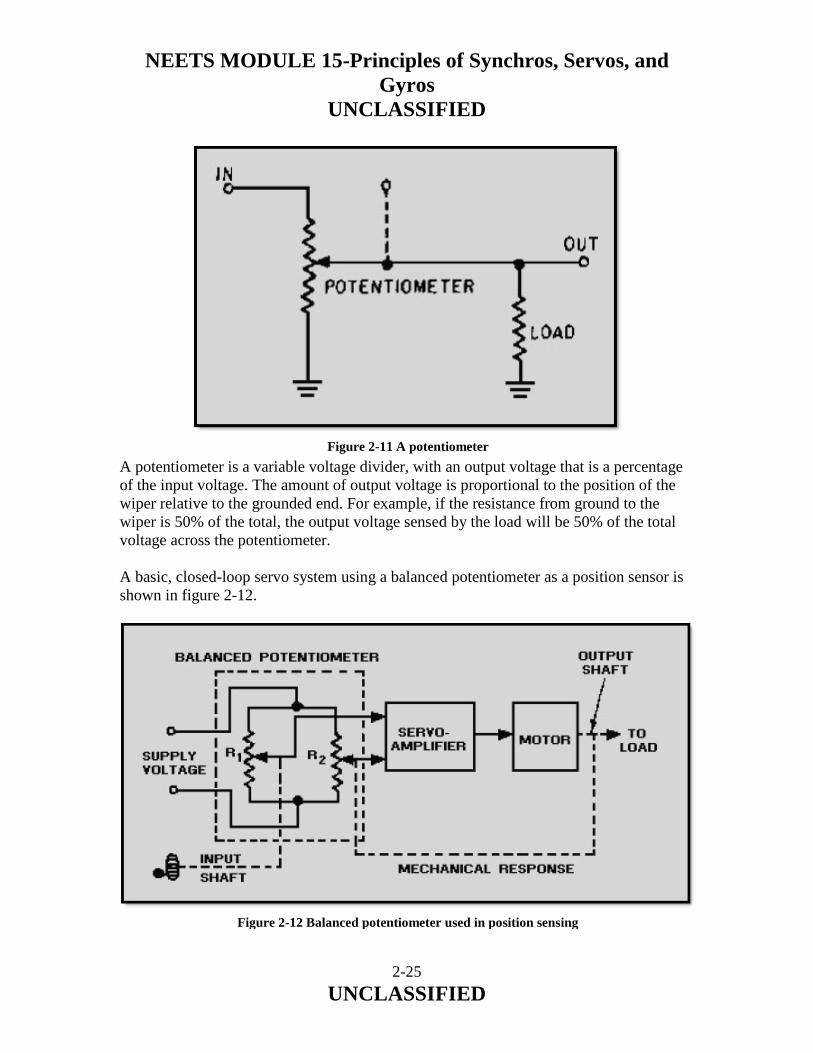
NEETS MODULE 15-Principles of Synchros, Servos, and Gyros
UNCLASSIFIED
2-25 UNCLASSIFIED
A potentiometer is a variable voltage divider, with an output voltage that is a percentage of the input voltage. The amount of output voltage is proportional to the position of the wiper relative to the grounded end. For example, if the resistance from ground to the wiper is 50% of the total, the output voltage sensed by the load will be 50% of the total voltage across the potentiometer. A basic, closed-loop servo system using a balanced potentiometer as a position sensor is shown in figure 2-12.
Figure 2-11 A potentiometer
Figure 2-12 Balanced potentiometer used in position sensing

NEETS MODULE 15-Principles of Synchros, Servos, and Gyros
UNCLASSIFIED
2-26 UNCLASSIFIED
The command input shaft is mechanically linked to R1, and the load is mechanically linked to R2. A supply voltage is applied across both potentiometers. The system is designed so that when the input and output shafts are in the same angular position, the voltages from the two potentiometers are equal and no error voltage is felt at the amplifier input. If the input shaft is rotated, moving the wiper contact of R1, an error voltage is applied to the servo amplifier. This error voltage is the difference between the voltages at the wiper contents of R1 and R2. The output of the amplifier causes the motor to rotate the load and the wiper contact of R2. This continues until both voltages are again equal. When the voltages are equal, the motor stops. In effect, the position of the output shaft has been sensed by the balanced potentiometer. Q-18. When the input and output wipers of a balanced potentiometer are in the same angular position. What is the value of the error voltage?
2.5.2 ERROR DETECTORS
Electrical error detectors may be either ac or dc devices, depending upon the requirements of the servo system. An ac device used as an error detector must compare the two signals and produce an error signal in which the phase and amplitude will indicate the direction and amount of control, respectively, that are necessary for correspondence. A dc device differs in that the polarity of the output error signal determines the direction of the necessary correction. We will discuss in the following paragraphs various devices that are commonly used in servo systems. 2.5.2.1 Summing Networks
Summing networks, as we mentioned earlier, are used as error detectors in servo applications where the servo output must be proportional to the algebraic sum of two or more inputs. A typical circuit is shown in figure 2-13.

NEETS MODULE 15-Principles of Synchros, Servos, and Gyros
UNCLASSIFIED
2-27 UNCLASSIFIED
As in the case of potentiometers, the networks may use either ac or dc voltage, with the phase or polarity of the input voltage determining whether the signals are additive or subtractive. Refer to figure 2-13. If two input signals E1 and E 2 are applied to the network, the network will provide an error voltage output that is proportional to the algebraic sum of the two signals. The servo motor drives the load and also a tachometer that supplies feedback voltage to resistor Rf. Resistor Rf nulls the error signal. In some installations, the servo motor may position the wiper arm of a potentiometer instead of driving a tachometer to supply the feedback voltage. 2.5.2.2 E-Transformers
The E-transformer is a type of magnetic unit that is used as an error detector in systems in which the load is not required to move through large angles. In the basic E-transformer shown in figure 2-14, an ac voltage is applied to the primary coil (2) located on the center leg of the laminated, E-shaped core. Two secondary coils (1 and 3) are wound series-opposing on the outer poles of the core. The magnetic coupling between the primary (coil 2) and the two secondaries varies with the position of the armature. The armature can be physically moved left or right in the magnetic circuit by mechanical linkage to the load. This changes the reluctance between either pole and the armature.
Figure 2-13 Summing network as an error detector

NEETS MODULE 15-Principles of Synchros, Servos, and Gyros
UNCLASSIFIED
2-28 UNCLASSIFIED
When the armature is located in the center of the E-shaped core, as shown in the figure, equal and opposite voltages are induced in the secondary coils. The difference between them is zero. Thus, the voltage at the output terminals is also zero. But, if the armature is moved, say to the tight, the voltage induced in coil 1 increases, while the voltage induced in coil 3 decreases. The two voltages are then unequal, so that the difference is no longer zero. A net voltage results at the output terminals. The amplitude of this voltage is directly proportional to the distance the armature has been moved from its center position. The phase of this output voltage, relative to the ac on the primary, controls the direction the load moves in correcting the error. The basic E-transformer will detect movement of the armature in one axis only (either the horizontal or vertical depending upon the way the unit is mounted). To detect movement in both the horizontal and vertical axes, a CROSSED-E-TRANSFORMER is used. If you place two E-transformers at right angles to each other and replace the bar armature with a dome-shaped one (fig. 2-15), you have the basic configuration of what is known as the crossed-E transformer, or pickoff. In most applications the dome-shaped armature is attached to a gyro, and the core assembly is fixed to a gimbal, which is the servo load.
Figure 2-14 Basic-E transformer

NEETS MODULE 15-Principles of Synchros, Servos, and Gyros
UNCLASSIFIED
2-29 UNCLASSIFIED
The crossed-E transformer assembly consists of five legs (poles). Each leg is encased by a coil. The coil around the center leg is the primary, which is excited by an alternating voltage. The remaining four coils are the secondaries. From this view, you can see how it gets the name, crossed-E. When the reluctance dome (armature) is moved to the left of center, more flux links the left leg with the primary coil, and the voltage induced in the left secondary increases. The right leg has fewer flux linkages with the center coil; therefore, the voltage induced in the right coil will be less than that in the left coil. Thus there will now be a net voltage out of the pickoff. The phase of the output will be that of the larger voltage. If the dome were moved to the right, the opposite condition would exist. From this brief description, you can see that the crossed-E transformer works on the same fundamental principle as the basic type described earlier. The major difference between the two is in shape and the number of secondaries, and in the fact that the armature has universal movement. 2.5.2.3 Control Transformers
A commonly used magnetic error detector is the synchro-control transformer, which is used as a control device in servo systems. Recall that we covered the CTs operation in depth in chapter 1 of this module, and discussed its application to the servo system earlier in this chapter.
Figure 2-15 Crossed-E transformer

NEETS MODULE 15-Principles of Synchros, Servos, and Gyros
UNCLASSIFIED
2-30 UNCLASSIFIED
As an error detector, the CT compares the input signal impressed upon its stator with the angular position of its rotor, which is the actual position of the load. The output is an electrical (error) signal taken from the rotor, which is the difference between the ordered position and the actual position of the load. A primary advantage of the CT over other types of error detectors is its unlimited rotation angle; that is, both the input and the output to the synchro control transformer may rotate through unlimited angles. A disadvantage is that the output supplied to the servo amplifier is always an ac error signal, and must be demodulated if it is to be used in a dc servo system. Q-19. In the output of an ac error detector, what indicates the (a) direction and (b) amount of control necessary for correspondence?
Q-20. What two basic types of magnetic devices are used as error detectors?
2.5.3 Rate Generator (Tachometer)
As we mentioned earlier, the tachometer in the velocity servo system is the heart of the feedback loop. It is used to sense the speed (velocity) of the load. The tachometer is sometimes referred to as a RATE GENERATOR. Whatever the name, it is a small ac or dc generator that develops an output voltage (proportional to its rpm) whose phase or polarity depends on the rotor's direction of rotation. The dc rate generator usually has permanent magnetic field excitation. The ac rate generator field is excited by a constant ac supply. In either case, the rotor of the tachometer is mechanically connected, directly or indirectly, to the load.

NEETS MODULE 15-Principles of Synchros, Servos, and Gyros
UNCLASSIFIED
2-31 UNCLASSIFIED
2.5.3.1 The AC Rate Generator
One type of ac rate generator used widely in the past is the drag-cup type. The tachometer generator shown in figure 2-16 has two stator windings 90º apart, and an aluminum or copper cup rotor. The rotor rotates around a stationary, soft-iron, magnetic core. One stator winding is energized by a reference ac source. The other stator winding is the generator output, or secondary winding the voltage applied to the primary winding produces a magnetic field at right angles to the secondary winding when the rotor is stationary, as shown in view A. When the rotor is turned by mechanical linkage from the load, it distorts the magnetic field so that it is no longer 90 electrical degrees from the secondary winding. Flux lines cut the secondary winding, and a voltage is induced in the output winding as shown in views B and C. The amount of magnetic field that will be distorted is determined by the speed of the rotor. Therefore, the magnitude of the voltage induced in the secondary winding is proportional to the rotor's velocity (speed).
Figure 2-16 Ac drag-cup rate generator

NEETS MODULE 15-Principles of Synchros, Servos, and Gyros
UNCLASSIFIED
2-32 UNCLASSIFIED
The direction of the magnetic field's distortion is determined by the direction of the rotor's motion. If the rotor is turned in one direction, the lines of flux will cut the secondary winding in one direction. If the motion of the rotor is reversed, the lines of flux will cut the secondary winding in the opposite direction. Therefore, the phase of the voltage induced in the secondary winding, measured with respect to the phase of the supply voltage, is determined by the direction of the rotor's motion. The phase relationship is shown in views B and C at the output winding. The frequency of the tachometer generator output voltage is the same as the frequency of the reference voltage. The output voltage is generated by the primary alternating flux field cutting the secondary winding; therefore, the output voltage must have the same frequency as the supply voltage. Other types of ac tachometer generators have a squirrel-cage rotor. Otherwise their construction and principles of operation are identical to the drag-cup type. 2.5.3.2 The DC Rate Generator
The dc rate generator uses the same principles of magnetic coupling as the ac rate generator. The dc rate generator, however, has a steady (nonfluctuating) primary magnetic field. This magnetic field is usually supplied by permanent magnets. The amount of voltage induced in the rotor winding is proportional to the number of magnetic flux lines cut. The polarity of the output voltage is determined by the direction in which the rotor cuts the lines of magnetic flux. The physical makeup and theory of operation of the dc rate generator (tach) is very similar to the dc generator (NEETS, Module 5, Generators and Motors). The only major differences are size and the prime mover. The tach is much smaller and is linked mechanically to the servo motor or load instead of to a prime mover. Tachometer generators are used in servo systems to supply velocity or damping signals and are sometimes mounted on or in the same housing as the servo motor. Q-21. What is the basic difference between the primaries of ac and dc rate generators?

NEETS MODULE 15-Principles of Synchros, Servos, and Gyros
UNCLASSIFIED
2-33 UNCLASSIFIED
2.5.4 MODULATORS IN THE SERVO SYSTEM
Because of problems associated with dc amplifiers, such as drift (where the output varies with no variation of the input signal), the ac amplifier is more widely used in servo applications. This creates a need for a device to convert a dc error signal into an ac input for the servo amplifier. Such a device is referred to as a MODULATOR. Modulator and modulating techniques vary with different types of electronic equipment. The modulator in the servo system performs a completely different function than its counterparts in radar or communications systems. The servo modulator converts a dc error signal into an ac error signal. The modulator uses two inputs to produce the ac error signal. One input is the dc error signal (for example from an input potentiometer); the other input is an ac reference voltage from some other source, such as the swp's ac supply system. The ac output error signal must contain the same control information that is contained in the original dc error signal. This is done in the following manner: 1. The phase between the ac output and the ac reference signal is determined by the polarity of the dc input signal. The phase of the ac output indicates the direction of error (direction of the load movement). 2. The amplitude of the ac output is proportional to the amplitude of the dc input signal and indicates the amount of error signal (speed or angular displacement of the load). These relationships of phase and amplitude must be maintained to ensure that the load will move the desired amount, or the proper speed, and in the right direction. A typical modulator that you will see in a servo system is the CRYSTAL DIODE MODULATOR. The following paragraphs provide a brief explanation of how this modulator works.

NEETS MODULE 15-Principles of Synchros, Servos, and Gyros
UNCLASSIFIED
2-34 UNCLASSIFIED
2.5.4.1 Crystal Diode Modulators
The crystal diode modulator (fig. 2-17) consists of a diode bridge and a transformer network. When the ac reference voltage is applied to transformer T1, diodes CR 2 and CR3 conduct during the negative half-cycle. Conversely, diodes CR1 and CR4 conduct on the positive half-cycle. The diodes will conduct under these conditions because of the 180º phase reversal across T1. Current flow during the positive and negative half-cycles is represented by dotted arrows and solid arrows, respectively. Suppose a positive, dc error signal is applied during the negative-going ac input half-cycle at the primary of T1. Current will flow from ground, through the upper half of the primary winding of transformer T2, through diode CR2, and through the upper half of the secondary winding of transformer T1 to the dc source. This produces a positive-going voltage (error signal) across the secondary of T 2 (the first half-cycle of the output signal). On the positive-going ac input reference voltage half-cycle, current will flow from ground, through the lower half of the primary of transformer T2, through diode CR4, and through transformer T1 to the dc error signal source. This produces a negative-going voltage (error signal) across the secondary of T 2 (completing the cycle of the ac input reference). Notice that the error signal is 180º out of phase with the reference signal.
Figure 2-17 Crystal diode modulator

NEETS MODULE 15-Principles of Synchros, Servos, and Gyros
UNCLASSIFIED
2-35 UNCLASSIFIED
If a negative dc error signal is applied to the modulator, under the same conditions of ac reference signal, current flow through the circuit will be reversed. Keep in mind that this occurs, for example, when the load approaches the desired position from an opposite direction. This circuit will work with either a positive or a negative dc input signal, but only one condition will exist at any given time. With a negative dc error applied, current will flow from the dc error signal source through diodes CR3 and CR 1 (on different half-cycles of the ac reference) to ground. This causes an ac voltage to be produced across the secondary of T2 in the same manner as previously described with the positive dc error signal input. The only difference is that current will flow through the upper and lower halves of T2 in a different direction (toward ground) and cause the output to be in phase with the ac reference signal. In summary, the modulator produced an ac output, either in phase or 180º out of phase with the ac reference signal, depending upon the polarity of the dc input signal. The amplitude of the output will be proportional to the dc input signal amplitude and at the frequency of the ac reference voltage. Q-22. What is the purpose of a modulator in a servo system?
2.5.5 Demodulators In The Servo System
As you know, servo systems use both ac and dc servo motors depending upon the requirements of the system. Systems that are required to move light loads at constant speed use ac motors. Systems that are required to move heavy loads with a wide speed range use dc motors. When the requirements of the system call for a dc motor or other dc devices, the ac error signal within the servo system must be converted to a dc error signal before being fed to the dc servo amplifier. The conversion is made by the circuit known as a DEMODULATOR. As with the modulator, the demodulator maintains the same relationships between its input and output signals. Just like the modulator, the demodulator's output amplitude is proportional to its input signal and its output polarity is determined by the phase of the input signal. These relationships, as in the modulator you just studied, are necessary so the "new" error signal will control the servo motor in the desired manner.

NEETS MODULE 15-Principles of Synchros, Servos, and Gyros
UNCLASSIFIED
2-36 UNCLASSIFIED
2.5.5.1 Diode Demodulator
One example of a servo demodulator is the DIODE DEMODULATOR, sometimes called a phase detector, shown in figure 2-18. This circuit is used in servo systems because it not only converts ac to dc, but it is also able to distinguish the phase of the ac signal by comparing it to a reference voltage. Do not confuse this circuit with other phase detector circuits, such as those used in radar or communications systems. This demodulator (phase detector) distinguishes signals that are either in phase or 180º out of phase. For this reason this circuit is useful in servo systems where the ac output from the error detector (CT) is either in phase with the reference signal or 180º out of phase. Whatever type of error detector is used in the servo system, the reference voltage to the error detector and to the demodulator must be IN PHASE with each other for the demodulator to do its job. As shown in figure 2-18, the anodes of the two diodes are supplied with the same reference voltage.
Figure 2-18 Diode demodulator

NEETS MODULE 15-Principles of Synchros, Servos, and Gyros
UNCLASSIFIED
2-37 UNCLASSIFIED
With no ac error input signal applied to T2 (quiescent state), both diodes will conduct equally on the positive half-cycle of the reference voltage. The voltage drops across R11 and R2 are equal. This results in the two output terminals being at the same potential; therefore, the output voltage is zero for the positive half-cycle. During the negative half-cycle, a negative voltage is felt on the anodes of both diodes, both diodes are cut off, and zero potential is felt across the output terminals. The circuit will remain in this condition until an ac error signal is applied. As we make this circuit work, you will notice that CR1 will conduct when the input signal is in phase with the reference voltage and then only on the positive half-cycle. CR2 will remain in cutoff unless the phase relationship between the ac error signal and the reference voltage changes by 180º. At this time CR1 will cut off. This change could be brought about by the error detector in the servo system sensing a change in the direction of the load. Effectively, we have a one-diode circuit for one direction of rotation. Assume that an ac error signal is applied to T2, making the anode of CR1 positive and the anode of CR 2 negative. At the same time, the reference voltage on the anodes of CR1 and CR2 is on its positive half-cycle. Under these conditions, CR1 will conduct and CR2 will be cut off. A positive voltage will be developed across R1 and felt on the output terminals. During the negative half-cycle, a negative voltage will be felt on the anodes of CR1, and CR2 and will cut them off. The output of the circuit for one complete cycle of the reference signal will be a filtered, pulsating, dc voltage. As long as the input and reference signals are in phase, the circuit acts as a half-wave rectifier and a filter network. As we mentioned earlier, this circuit will also respond to a 180º phase reversal between the input and reference signals. For instance, when the error signal applied to T2 is 180º out of phase with the reference signal, CR2 conducts and CR 1 cuts off, causing the output voltage to change polarity. You may encounter variations of the diode phase detector; however, they all depend on the same basic principle of operation. To quickly summarize, the demodulator converted the ac input signal to a dc error signal. The polarity of the dc error signal was determined by the phase relationship between the ac error input signal and the reference signal. The amplitude of the dc error signal was directly proportional to the magnitude of the ac input signal. Q-23. What is the purpose of a demodulator in a servo system?

NEETS MODULE 15-Principles of Synchros, Servos, and Gyros
UNCLASSIFIED
2-38 UNCLASSIFIED
2.5.6 Servo Amplifiers
The servo amplifiers previously discussed were used in servo systems to amplify either the ac or dc error signal to a sufficient amplitude to drive the servo motor. These amplifiers are the same amplifiers in principle as covered in NEETS Module 8, Amplifiers. The basic amplifier chosen for use in the servo system must have the following characteristics: 1. Flat gain versus frequency response over the broad band of frequencies of interest. 2. Minimum phase shift with a change in input signal (zero phase shift is desired, but a small amount of phase-shift is acceptable, if constant). 3. A low output impedance. 4. A low noise level. Up to this point in our discussion of servos, the amplifiers have been directly connected to the motor that drove the load. Servo amplifiers are also used within the system itself to amplify the error signal. For example, the signal from the demodulator or filter network may require additional amplification to maintain signal strength. In cases where the amplifier is used to feed large drive motors, to move large loads, the basic electronic amplifier that was presented earlier in this training series is not adequate to do the job. This type of work is done by large power amplifying devices such as the amplidyne generator (NEETS, Module 5, Generators and Motors) and the MAGNETIC AMPLIFIER, which we will discuss later in this chapter. 2.5.7 AC Servo Motors
Large ac motors are too inefficient for servo use. To move large loads, the ac motor draws excessive amounts of power, and is difficult to cool. Hence, ac servo motors are used primarily to move light loads. Most of the ac servo motors are of the two-phase or split-phase induction type. Fundamentally, these motors are constant-speed devices, although their speeds can be varied within limits by varying the amplitude of the voltage to one of the motors stator windings. When the load becomes heavy, the workhorse dc servo motor is used.

NEETS MODULE 15-Principles of Synchros, Servos, and Gyros
UNCLASSIFIED
2-39 UNCLASSIFIED
2.5.8 DC Servo Motors
The control characteristics of dc servo motors are superior to those of ac servo motors. The dc servo motor can control heavy loads at variable speeds. Most dc servo motors are either the permanent magnet type, which are used for light loads, or the shunt field type, which are used for heavy loads. The direction and speed of the dc motor's rotation is determined by the armature current. An increase in armature current will increase the motor's speed. A reversal of the motor's armature current will change the motor's direction of rotation more thorough explanations of ac and dc motors are given in NEETS Module 5, Generators and Motors. 2.5.9 Synchronizing Circuits
As we explained in chapter 1, the use of a multi-speed synchro transmission system increases the accuracy of data transmission. The accuracy of the servo system depends in part upon the accuracy of the input fed from the synchro system. For example, a dual-speed synchro system operating in conjunction with a servo system uses two CTs (one coarse and one fine) to define a quantity accurately. This is done by feeding the output of the COARSE CT to the servo amplifier when the system is far out of correspondence and then shifting to the output of the FINE CT when the system is within 2 or 3 degrees of synchronization. A circuit that will perform this job is known as a SYNCHRONIZING NETWORK. A synchronizing network (also called a crossover or switching network) senses how far the servo load is from the ordered position and then switches either the coarse signal or the fine signal into control. The signal selected by the circuit is the input to the amplifier. The selection is based on the size of the error signals the circuit receives. The coarse signal is the predominant factor in the selection, since it is a measure of the servo's output position throughout its limit of motion. The coarse signal drives the system into approximate synchronization, and then the fine signal is shifted into control. 2.5.9.1 Semiconductor-Diode Synchronizing Network
The SEMICONDUCTOR-DIODE SYNCHRONIZING NETWORK is fairly common and typical of the type used in servo systems. Let's take a look at a circuit that uses this technique. Figure 2-19 is an illustration of the circuit. In the following explanation, we will assume that the system is far out of correspondence (more than 3º). At this time, the coarse signal is large in amplitute. With this condition, CR 3 and CR4, or CR5 and CR6, will be forward-biased, depending upon the polarity of the input signal. This will cause current to flow through R1.

NEETS MODULE 15-Principles of Synchros, Servos, and Gyros
UNCLASSIFIED
2-40 UNCLASSIFIED
The voltage developed across R1 is felt on one leg of the summing network. A large amplitude fine signal CANNOT be present in the summing network, because CR1 and CR 2 are designed to limit the fine amplitude to a small value. With this condition present at the summing network, the coarse signal maintains control and drives the load toward correspondence. When the load is within 3º of correspondence, the coarse signal is no longer large enough to forward bias the coarse diode network. The effect of this is to cause a large impedance across the diode network, which then drops most of the coarse signal. Practically no coarse signal voltage is felt across R1 and one leg of the summing network. On the other hand, the fine signal is also small at this time, since the load is close to correspondence. Small fine signals are unaffected by CR 1 and CR2. Therefore, the small fine signal is impressed across the summing network. With the fine signal being the only signal felt at the summing network, it takes control and drives the load to the exact point of correspondence. There are various types of synchronizing circuits used in servo systems. Some applications call for electron tubes, relays, and different types of semiconductor diodes. The theory of the specific type you will encounter in servo equipments will be explained in detail in the equipment's technical manual. Q-24. What is the purpose of a synchronizing network in a servo system?
Figure 2-19 Semiconductor diode synchronizing network

NEETS MODULE 15-Principles of Synchros, Servos, and Gyros
UNCLASSIFIED
2-41 UNCLASSIFIED
2.5.10 Magnetic Amplifiers
As we stated earlier in this chapter, various types of servo amplifiers are used to drive servo motors. When the amplifier is required to produce a large amount of power, the conventional electronic amplifier becomes less efficient than some other types. The following is a brief discussion of a typical magnetic amplifier used in a servo system where large amounts of power are required to move a heavy load. If you need to refresh your memory on the theory of the magnetic amplifier, refer to Module 8 of this training series, Amplifiers. 2.5.10.1 Magnetic Amplifiers in a Servo
Figure 2-20 illustrates a magnetic amplifier being used as the output stage of a servo amplifier.
Figure 2-20 Magnetic amplifier used to drive a servo motor

NEETS MODULE 15-Principles of Synchros, Servos, and Gyros
UNCLASSIFIED
2-42 UNCLASSIFIED
The output of the servo amplifier is connected to one of the motor windings (controlled winding W1). The other winding (uncontrolled winding W2) is connected across the ac source, in series with a capacitor. The capacitor provides the required 90º phase shift necessary to cause motor rotation. The phase relationship of the current through the two windings determines the direction of rotation of the servo motor. The magnetic amplifier consists of a transformer (T1), and two saturable reactors (L1 and L 2), each having three windings. The key point to the operation of this circuit lies in the fact that the error signal windings are connected in series-opposing while the bias windings are series-aiding. With the circuit in the quiescent state (no input), the dc bias voltage causes the dc bias current to equally and partially saturate both reactors (L1 and L2). The reactances of L1 and L2 now being equal result in canceling currents through the W1 windings of the servo motor. With only one input to the motor, it remains at rest. Now, let's apply an error signal to the error signal windings. L2 saturates and L1 is driven further out of partial saturation, because the error windings are in series-opposition. This results in the error signal aiding the bias current in reactor L 2 and tending to cancel the bias current in reactor L 1. The reactance of L2 is reduced, causing an increased current through the L2 circuitry. In the other circuit (L1), the reverse is true; its current decreases. This imbalance in the L1 and L2 circuitry results in current flow through W1, say from left to right, and causes the motor to turn. Reversing the polarity of the error signal causes the direction of motor rotation to change. This is done by saturating reactor L 1 instead of reactor L2 and causing current to reverse directions through W1. In the previous discussion, an ac motor was driven by the output of the magnetic amplifier. If a dc motor is required in the servo to move a heavy load, the ac output from the magnetic amplifier must be rectified.

NEETS MODULE 15-Principles of Synchros, Servos, and Gyros
UNCLASSIFIED
2-43 UNCLASSIFIED
NOTE: All of the components that have been described as units within a servo system are, in general, the same components used in many other electronic and electrical applications. The theory of these components has been discussed here and in other modules of the Navy Electricity and Electronics Training Series. If you have the desire or a need for an in-depth study of these components, the following are excellent references: • Electronics Installation and Maintenance Books, NAVSEA 0967-LP-000-0130, for synchro and servo subjects. • Electronics Installation and Maintenance Books, NAVSEA 0967-LP-000-0120, for the basic components of the servo system. These references should be available in the technical library of your ship or station. Q-25. What the three basic components make up the typical magnetic amplifier?
2.5.11 Multi-Loop Servo Systems
Now that we have gone through the various servo loops and their components, let's continue our discussion with a realistic application of a servo system. Very seldom will we find applications where one type of servo loop is used by itself. Usually several loops are combined through the use of various types of relays and switches. The many components of a complex system are caused to work together by switching them in and out as necessary. Figure 2-21 illustrates a practical application of a multi-loop servo system. You should be able to recognize by now the different loops and components that make up this system. Nothing is really new in the system; we discussed all the loops and components earlier in this chapter.

NEETS MODULE 15-Principles of Synchros, Servos, and Gyros
UNCLASSIFIED
2-44 UNCLASSIFIED
As shown by the relay conditions, the system is configured, in its normal state, as a closed-loop position servo. This is indicated by the heavy dark lines in the figure. An alternate configuration positions the load in this system by using the potentiometer. This is done by energizing relay K2, and switching the system to an open-loop configuration. At the same time, the deenergized contacts of K2 (1-3) open, thereby breaking the closed loop. The open loop is shown by the medium density lines in the figure. This loop is not as accurate as the closed loop, because the operator must intervene by turning the shaft of the potentiometer back to the zero voltage position to stop the load at the desired position. This type of circuit could be used by maintenance personnel to position the load for easy access to equipments, such as on an antenna or gun mount. The open loop can also function as a basic velocity loop by simply not returning the potentiometer to the zero position. This results in a constant error signal being present at the wiper arm of the potentiometer. With this condition, the load will continue to drive at some speed (rate) determined by the components in the loop. The last loop we will consider is the closed-loop velocity servo, indicated by the fine density lines. This loop is switched into operation by energizing K1. Notice that there are two inputs to the summing network with K1 energized, the electrical input through contacts 2-4 and the feedback from the tach through contacts 1-3. The two signals are compared in the summing network, and their difference is used as the error signal to drive the load. When a state of equilibrium is reached in the circuit, the load will be moving at the desired velocity.
Figure 2-21 Multi-loop servo system

NEETS MODULE 15-Principles of Synchros, Servos, and Gyros
UNCLASSIFIED
2-45 UNCLASSIFIED
2.6 SUMMARY
This chapter has provided information basic to understanding servo systems and their components. The following is a summary of specific points in the chapter. The OPEN-LOOP CONTROL SYSTEM is controlled directly, and only by an input signal. It has no feedback and is therefore less accurate than the closed-loop control system. The open-loop system usually requires an operator to control the speed and direction of movement of the output. The CLOSED-LOOP CONTROL SYSTEM is the most common type used in the Navy. It can respond and move loads quickly and with greater accuracy than the open-loop system. The closed-loop system has an automatic feedback system that informs the input that the desired movement has taken place. The SERVO SYSTEM is classified as a closed- loop system when it is capable of: 1. Accepting an order and defining the desired result, 2. Evaluating present conditions, 3. Comparing the desired result with present conditions and obtaining a difference or an error signal, 4. Issuing a correcting order, and changing the existing conditions to the desired result, and 5. Obeying the correcting order. The BASIC SERVO SYSTEM is normally made up of electromechanical parts, and consists of a synchro-control system, servo amplifier, servo motor, and some form of feedback. The POSITION SERVO has the goal of controlling the position of the load. In the ac position servo system, the amplitude and phase of the ac error signal determine the amount and direction the load will be driven.

NEETS MODULE 15-Principles of Synchros, Servos, and Gyros
UNCLASSIFIED
2-46 UNCLASSIFIED
In the dc position servo system, the amplitude and polarity of the dc error signal are used to determine the amount and direction the load will be driven. The VELOCITY SERVO is based on the same principle of error-signal generation as the position servo, except that the VELOCITY of the output is sensed rather than position of the load. When the velocity loop is at correspondence, an error signal is still present, and the load is moving at the desired velocity. The ACCELERATION SERVO is similar to the velocity and position servos except that the acceleration of the load is being sensed rather than the position or velocity. In this loop, the tachometer of the velocity loop is replaced with an accelerometer. TIME LAG is a servo characteristic defined as the time between the input of the signal and the actual movement of the load. Time lag is undesirable and is reduced through the use of high-gain amplifiers. Damping systems are then added to attain smooth, efficient operation. An OVERDAMPED system will not be subject to oscillations but takes an excessive amount of time to reach synchronization. An UNDERDAMPED system provides instant response to an error signal but results in the load oscillating about the point of synchronism. Somewhere between overdamped and underdamped, designers achieve adequate accuracy, smoothness, and a moderately short synchronizing time. DAMPING is used to stabilize a system-to minimize or eliminate the problem of overshoot. The simplest form of damping is FRICTION CLUTCH damping. MAGNETIC CLUTCH damping is similar to friction clutch damping. The difference is in how the flywheel is coupled to the shaft of the servo motor. Magnetic coupling uses a magnetic field to draw two friction plates together to produce damping. Another method uses the magnetic field set up by a pair of coils or one coil in conjunction with a conducting surface (flywheel) to produce damping. ERROR-RATE DAMPING is defined as a method of damping that "anticipates" the amount of overshoot. This form of damping corrects the overshoot by introducing a voltage in the error detector that is proportional to the rate of change of the error signal. The stabilization network used for error-rate damping consists of either an RC differentiating network or an integrating network. The components of the RC network are chosen to tailor the stabilization network to the requirements of the servo system.

NEETS MODULE 15-Principles of Synchros, Servos, and Gyros
UNCLASSIFIED
2-47 UNCLASSIFIED
FREQUENCY RESPONSE of a servo is the range of frequencies to which the system is able to respond in moving the load. The ideal system can respond to whatever frequencies are present in the input signal. Frequency response is a good way of judging servo performance. In a given servo system, good frequency response provides maximum stability and minimum time lag. The BANDWIDTH of a servo amplifier, ideally, must be able to accept only the range of frequencies that represent valid servo signals. Amplifier bandwidth is another compromise in achieving optimum servo operation. A POTENTIOMETER is one of the simplest position sensor devices and is generally used because of its small size, high accuracy, and output, which can be either ac or dc. Its primary disadvantages are limited motion, limited life due to wear, and high torque required to rotate the wiper contact. A BALANCED POTENTIOMETER in a closed-loop servo system is a voltage divider that functions as a position sensor and produces the error voltage that is fed to the servo amplifier. SUMMING NETWORKS can be used as error detectors in servo systems to add algebraically two or more inputs and a feedback error voltage. The E-TRANSFORMER is a magnetic error detector that can be used in systems limited by large angular movements. Output signals are either in phase, 180º out of phase, or zero, depending on the direction of the E-transformer's armature motion. The amplitude of the signal is determined by the amount of armature motion. The basic E-transformer can only detect motion in one axis. A CROSSED-E TRANSFORMER (or pickoff) is two E-transformers placed at right angles to each other. This type of error detector is capable of detecting error in both horizontal and vertical directions. A CONTROL TRANSFORMER (CT), when used as a magnetic error detector, can rotate through unlimited angles. The output of this type of CT is always an ac servo error signal that must be demodulated if it is used with a dc servo motor.
NEETS MODULE 15-Principles of Synchros, Servos, and Gyros
UNCLASSIFIED
2-48 UNCLASSIFIED
A RATE GENERATOR (tachometer), when used in the velocity servo loop, is the heart of the feedback loop. The tach senses velocity (speed) of the load. A tachometer can be either an ac or dc rate generator. The output frequency of the ac tach is the same as the reference frequency, varying only in phase depending on the direction of rotation. MODULATORS are used to change a dc error signal into an ac input error signal for servo amplifiers. This device is required when ac servo amplifiers are used instead of dc amplifiers. DEMODULATORS convert ac error signals to dc error signals. The dc signal is required to drive a dc servo amplifier. A SERVO AMPLIFIER used in an ac or dc servo system must have a flat gain, minimum phase shift, low output impedance, and low noise level. AC SERVO MOTORS are used in servo systems that move light loads. Large ac motors are too inefficient for servo use when large loads are to be moved. DC SERVO MOTORS can control heavy loads, and are widely used in servo systems. The speed and direction of the dc servo motor can be varied easily by varying the armature current. MAGNETIC AMPLIFIERS are used when power from a conventional servo amplifier is too small to drive large servo motors (either ac or dc). The MULTI-LOOP SERVO SYSTEM combines several closed and/or open servo loops together to control a common load.
NEETS MODULE 15-Principles of Synchros, Servos, and Gyros
UNCLASSIFIED
2-49 UNCLASSIFIED
ANSWERS TO QUESTIONS Q1. THROUGH Q25.
A-1. A system in which the precise movement of a large load is controlled by a relatively weak control signal.
A-2. Usually the operator senses the desired load movement and reduces the input to
stop the motor. A-3. Feedback. A-4. Input signal and feedback. A-5. To move the load and provide feedback data to the error detector. A-6. Classifications in accordance with position, velocity, and acceleration functions. A-7. Amount and direction of rotation. A-8. Hunting. A-9. Velocity loop senses velocity rather than position. When velocity loop is nulled,
an error signal is still present and the load continues to move. A-10. Tachometer. A-11. The closed-servo loop can regulate load speed under changing conditions. A-12. Underdamped. A-13. Overdamped. A-14. To minimize overshoot and/or oscillations. A-15. Anticipating. A-16. It should oscillate. A-17. Unwanted noise-generated frequencies are rejected. A-18. Zero.

NEETS MODULE 15-Principles of Synchros, Servos, and Gyros
UNCLASSIFIED
2-50 UNCLASSIFIED
A-19. (a) Phase. (b) Amplitude. A-20. E-transformer and control transformers. A-21. The method of primary excitation (ac and permanent magnet). A-22. To convert a dc error signal into an ac error signal. A-23. To convert an ac error signal into a dc error signal. A-24. To switch control of the amplifier between either the coarse signal and the fine
error signal. A-25. Two saturable reactors and a transformer.

NEETS MODULE 15-Principles of Synchros, Servos, and Gyros
UNCLASSIFIED
3-1 UNCLASSIFIED
3 GYROS
LEARNING OBJECTIVES
After you finish this chapter, you should be able to do the following: 1. Describe the characteristics of a gyroscope. 2. List the two basic properties of gyroscopes and explain them. 3. Describe the components of a universally mounted gyro. 4. Describe the factors that determine rigidity in a gyro. 5. List the factors that determine the direction of precession in a gyro. 6. Explain the right-hand rule for gyro precession. 7. Describe the term "Degree of Freedom" as it applies to gyros. 8. Explain the effect of apparent precession (apparent rotation). 9. Explain the purposes of erection systems. 10. Describe the use of gyros with only one degree of freedom. 11. Explain the purpose of an accelerometer. 12. Explain the principle on which accelerometers operate. 13. Explain the need for a pulse-counting accelerometer. 3.1 GYROS
The word gyroscope was first coined by a French scientist, Leon Foucault, in 1852. It is derived from the Greek words "gyro," meaning revolution, and "skopien," meaning to view. The gyroscope, commonly called a GYRO, has existed since the first electron was sent spinning on its axis. Electrons spin and show all the characteristics of a gyro; so does the Earth, which spins about its polar axis at over 1000 miles per hour at the Equator. The Earth's rotation about its axis provides the stabilizing effect that keeps the North Pole pointed within one degree of Polaris (the North Star). Any rapidly spinning object—a top, a wheel, an airplane propeller, or a spinning projectile—is fundamentally a gyroscope. Strictly speaking, however, a gyroscope is a mechanical device containing a spinning mass that is universally mounted; that is, mounted so it can assume any position in space. Figure 3-1 shows a model of a gyro. As you can see, a heavy wheel (rotor) is mounted so that its spin axis is free to turn in any direction. The wheel spins about axis X; it can turn about axis Y, and it can turn about axis Z. With this mechanical arrangement, the spinning wheel can assume any position in space.

NEETS MODULE 15-Principles of Synchros, Servos, and Gyros
UNCLASSIFIED
3-2 UNCLASSIFIED
3.2 BASIC PROPERTIES OF GYROSCOPES
Gyroscopes have two basic properties: rigidity and precession. Those properties are defined as follows: 1. RIGIDITY — The axis of rotation (spin axis) of the gyro wheel tends to remain in a fixed direction in space if no force is applied to it. 2. PRECESSION — The axis of rotation has a tendency to turn at a right angle to the direction of an applied force. The idea of maintaining a fixed direction in space is simple to illustrate. When any object is spinning rapidly, it tends to keep its axis pointed always in the same direction. A toy top is a good example. As long as the top is spinning fast, it stays balanced on its point. Because of this gyro action, the spinning top resists the tendency of gravity to change the direction of its axis. You can think of many more examples. A bicycle is easier to balance at high speed than when it is barely moving. At high speed, the bicycle wheels act as gyros, and tend to keep their axes (axles) parallel to the ground.
Figure 3-1 Gyro model, universally mounted
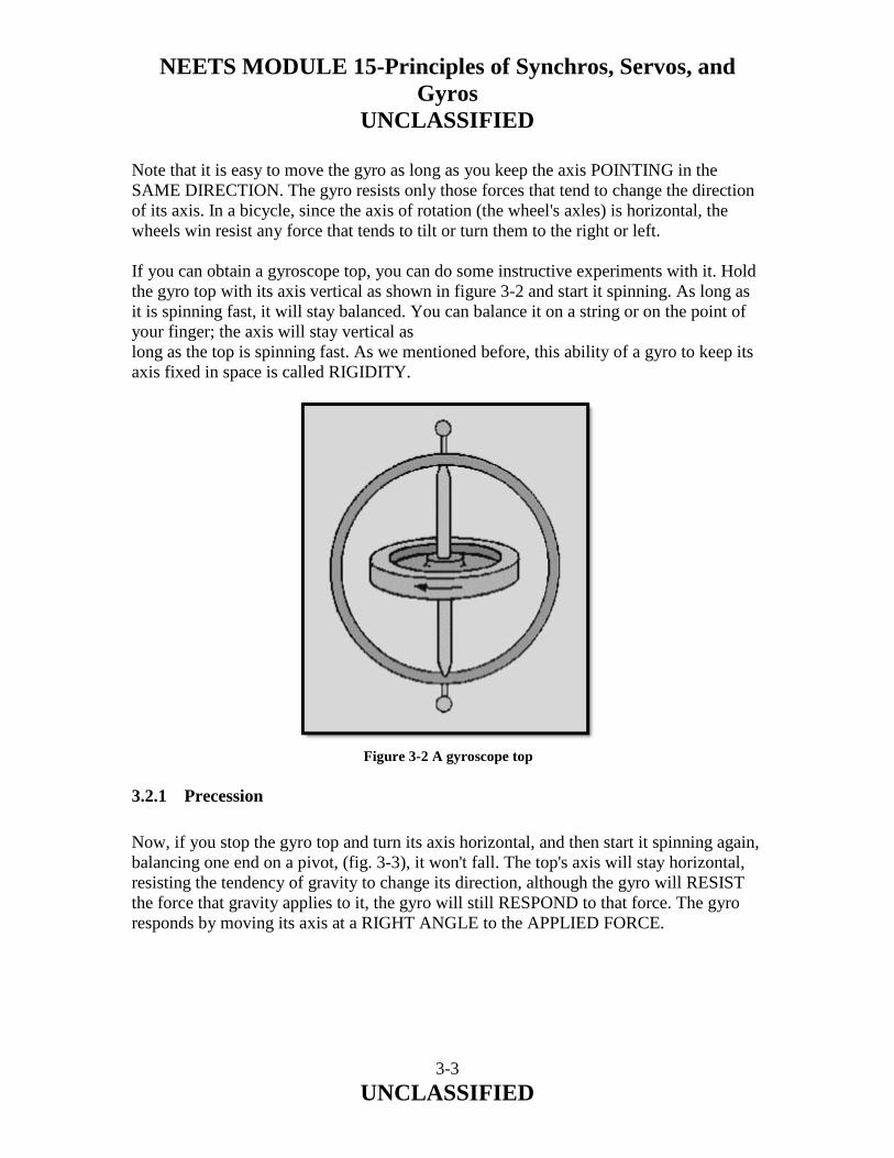
NEETS MODULE 15-Principles of Synchros, Servos, and Gyros
UNCLASSIFIED
3-3 UNCLASSIFIED
Note that it is easy to move the gyro as long as you keep the axis POINTING in the SAME DIRECTION. The gyro resists only those forces that tend to change the direction of its axis. In a bicycle, since the axis of rotation (the wheel's axles) is horizontal, the wheels win resist any force that tends to tilt or turn them to the right or left. If you can obtain a gyroscope top, you can do some instructive experiments with it. Hold the gyro top with its axis vertical as shown in figure 3-2 and start it spinning. As long as it is spinning fast, it will stay balanced. You can balance it on a string or on the point of your finger; the axis will stay vertical as long as the top is spinning fast. As we mentioned before, this ability of a gyro to keep its axis fixed in space is called RIGIDITY. 3.2.1 Precession
Now, if you stop the gyro top and turn its axis horizontal, and then start it spinning again, balancing one end on a pivot, (fig. 3-3), it won't fall. The top's axis will stay horizontal, resisting the tendency of gravity to change its direction, although the gyro will RESIST the force that gravity applies to it, the gyro will still RESPOND to that force. The gyro responds by moving its axis at a RIGHT ANGLE to the APPLIED FORCE.
Figure 3-2 A gyroscope top

NEETS MODULE 15-Principles of Synchros, Servos, and Gyros
UNCLASSIFIED
3-4 UNCLASSIFIED
The axis will tilt in a direction 90º away from the applied force. This is called PRECESSION. Figure 3-4 is another view of the same gyroscope. Its far end is still balanced on the pivot. Gravity is pulling down on the gyro. If the gyro rotor is turning in the direction shown by the arrow, the near end of the frame (axis) will move to the left. If the rotor were turning in the opposite direction, the frame would move to the right. Note that in each of these examples the direction of movement was displaced from the applied force (gravity) by 90º. The axis stays horizontal, but the gyroscope responds to the force of gravity by rotating around the pivot.
Figure 3-3 Gyro top with axis horizontal
Figure 3-4 Gyro precession

NEETS MODULE 15-Principles of Synchros, Servos, and Gyros
UNCLASSIFIED
3-5 UNCLASSIFIED
Gyro action may be summarized as follows: A spinning gyro tends to keep its axis pointing in the same direction. This is called RIGIDITY. If you apply a force that tends to change the direction of the spin axis, the axis will move at a right angle to the direction of the applied force. The direction of precession will be 90º clockwise from the applied force if the rotor is spinning clockwise (when viewed from the "free" end of the rotor's axis); if the rotor is spinning counterclockwise, the precession will be 90º counterclockwise. If the axis is horizontal, and you try to tilt it, the axis will turn. If the axis is horizontal, and you try to turn it, the axis will tilt. This second characteristic of a gyro is called PRECESSION. Because of precession, we can control the direction that the spin axis points. This enables us to aim the spin axis where we want it to point. Without precession, the rigidity of the gyro would be useless. Q-1. Can any rapidly spinning object be considered a gyroscope?
Q-2. In the drawing in figure 3-1, which axis is the gyro spin axis?
Q-3. What gyro property causes the gyro to remain in a fixed position?
Q-4. What type(s) of force does a gyro resist?
Q-5. In what direction will a gyro precess in response to an outside force?

NEETS MODULE 15-Principles of Synchros, Servos, and Gyros
UNCLASSIFIED
3-6 UNCLASSIFIED
3.3 BASIC GYRO ELEMENTS
The gyro shown in figure 3-5 is a basic, universally mounted gyro, sometimes called a free gyro. Its components are rotor, inner gimbal, outer gimbal, and base or support. Gimbals are devices that permit the rotor to assume any position and retain that position when the support is tipped or repositioned. Note that in figure 3-5, the support may be moved about all axes without the rotor position being disturbed. As you know, gravity is a force that acts along parallel lines upon each particle of matter. A plot of the resultant gravitational force on a body such as a gyro would be equivalent to the sum of these separate forces. The point at which the resultant force is applied is called the CENTER OF GRAVITY. To have a balanced gyro, the center of gravity must be located at the intersection of the three axes of the gyro.
Figure 3-5 Basic universally mounted gyro

NEETS MODULE 15-Principles of Synchros, Servos, and Gyros
UNCLASSIFIED
3-7 UNCLASSIFIED
3.4 RIGIDITY
A gyroscope is a spinning body that tends to keep its spin axis rigidly pointed in a fixed direction in space. What do we mean by "fixed direction in space"? A fixed direction on Earth is by no means fixed in space, because the Earth turns once on its axis every 24 hours, and makes a complete revolution around the sun every year. The sun itself is moving through space, taking the Earth and the other planets with it. Because of these motions, the expression "fixed direction in space" as used in this explanation is theoretical. For all practical purposes, we can say a line from the Earth to a distant star is a fixed direction in space. If the spin axis of a spinning gyro is pointed at a distant star, it will remain pointed at the star as the Earth turns. Gyro rigidity is the strength with which a gyro resists any external force that would tilt its rotor spin axis. There are three factors that determine gyro rigidity: weight of the rotor, distribution of this weight, and rotor speed. The gyro can be considered as an enclosed mechanical system. The energy in the system is equal to the input energy. Hence the energy necessary to spin the gyro rotor is contained in the rotor as angular momentum, which is a function of rotor weight and the speed of rotor rotation. The heavier the gyro rotor, the larger the torque necessary to spin it, and the greater the angular momentum of the rotor. If we have two rotors with identical shapes but different weights spinning at the same velocity, the heavier of the two will be more rigid in its spin axis since it has the greater angular momentum. Now let's look at the effect of weight distribution in the rotor of a gyro. Consider three rotors of the same weight, as shown in figure 3-6, view (A), view (B), and view (C), with the diameter of one rotor half the diameter of the other two. Now, when we spin these rotors at the same speed, we find that the rotors with the greater diameter are much more rigid than the one with the smaller diameter. Next, we find that we can make the rotors equally rigid by causing the rotor with the smaller diameter to spin faster than the larger rotors. Thus rigidity depends both on speed and distribution of weight. The weight of the larger rotor being farther away from the axis of spin causes it to be more rigid. This effect is even more pronounced if we shape the rotor as shown in view C of figure 3-6. Shifting as much weight as possible to the outer rim of the rotor increases rigidity even further.

NEETS MODULE 15-Principles of Synchros, Servos, and Gyros
UNCLASSIFIED
3-8 UNCLASSIFIED
Figure 3-6A Gyro rotors with equal weight and unequal diameters
Figure 3-6B.—Gyro rotors with equal weight and unequal diameters
Figure 3-6C.—Gyro rotors with equal weight and unequal diameters

NEETS MODULE 15-Principles of Synchros, Servos, and Gyros
UNCLASSIFIED
3-9 UNCLASSIFIED
Q-6. A universally mounted gyro has how many gimbals?
Q-7. What factors determine the rigidity of a gyro?
Q-8. Which gyro rotor in figure 3-6, view (A) view (B) view (C), will have the greatest rigidity if all are rotated at the same speed?
3.5 PRECESSION
To provide useful information, a gyro's spin axis must be related to some reference, usually the Earth's surface. This is done by using the second fundamental property of a gyro—PRECESSION. The gyro is precessed until its spin axis is pointed in the desired direction. So far we have covered precession in very general terms. The following paragraphs will cover this "gyro action" in more detail. We can show precession by using the models in figure 3-7, view (A) and view (B). The gyro wheel is mounted so it is free to have its spin axis pointed in any direction. Here the wheel rotates in a flat loop called the gyro case (inner gimbal). The gyro case is pivoted in the gimbal ring (outer gimbal) and the gyro can swing about the Z axis. The gimbal ring itself turns on pivots that connect it to the fork (support). The fork permits the gyro to tilt from side to side about the Y axis.
Figure 3-7A Gyro action

NEETS MODULE 15-Principles of Synchros, Servos, and Gyros
UNCLASSIFIED
3-10 UNCLASSIFIED
Regardless of how the fork is placed, the spinning gyro wheel is free to lie in any given plane. That's why it is called a free gyroscope in this type of mounting. To show the effect of precession, we can push down on the gimbal ring at point A at the nearer end of the Z-Z axis. (See view A of figure 3-7.) You might expect the ring to tilt around the Y-Y axis. Instead, the gyro case will tilt about the Z-Z axis. You can see the effect of this precession in view B. Here's a rule that applies to all spinning gyros: THE GYRO WILL ALWAYS PRECESS AT RIGHT ANGLES TO THE DIRECTION OF THE APPLIED FORCE. Look at view A again. If we keep pushing down on the gimbal ring at point (A), the gyro case will keep turning until the spin axis of the gyro wheel is horizontal. Then there will be no further precession. At this point the gyro wheel will be spinning in the same direction in which the applied force is pushing.
Figure 3-7B.—Gyro action

NEETS MODULE 15-Principles of Synchros, Servos, and Gyros
UNCLASSIFIED
3-11 UNCLASSIFIED
Here's another rule: A GYRO ALWAYS PRECESSES IN A DIRECTION TENDING TO LINE ITSELF UP SO THAT ITS ROTOR SPINS IN THE SAME DIRECTION THAT THE APPLIED FORCE IS TRYING TO TURN IT. In other words, the direction of spin chases the applied force. When the direction of spin and the applied force are in the same direction, precession stops. Now, compare the spin (X) axis in the two parts of figure 3-7. In view A, the spin axis is vertical. In view B, the spin axis has moved from the vertical until it is much closer to being horizontal. By applying the right amount of force in the right place, we have a method of "aiming" the spin axis so that it points to the specific fixed direction in space where we want it. The property of PRECESSION makes the property of RIGIDITY useable. You should understand that most forces, when applied to the gyro mounting, do not cause precession. For instance, you can swing the fork around in any direction, and the motion will merely be taken up in the Y-Y and Z-Z axes. Similarly, a force applied lengthwise along one of the axes will have no effect. Any force acting through the center of gravity of the gyroscope does not change the angle of the plane of rotation but moves the gyroscope as a unit. The position of its spin axis in space is not changed. Such forces as those stated above, operating through the center of gravity, are forces of TRANSLATION. In other words, the spinning gyroscope may be moved freely in space by means of its supporting frame, without disturbing the plane of rotation of the rotor. This condition exists because the force that is applied through the supporting frame, acting through the center of gravity produces no torque on the gyro rotor. ONLY THOSE FORCES TENDING TO TILT THE GYRO WHEEL ITSELF WILL CAUSE PRECESSION. Let's consider further the important characteristic of gyroscopic precession. For a given amount of force, the rate of precession of a gyro is governed by the weight, shape, and speed of the rotor. These factors are the same as those that determine the rigidity of a gyro. Therefore, there is a definite relationship between the rigidity of a gyro and the rate at which a given force will cause it to precess. The greater the rigidity of a gyro, the more difficult it is to cause precession, and the less precession there will be for a given force. A gyro will resist any force that attempts to change the direction of its spin axis. However, it will move (precess) in response to such force; NOT in the direction of the applied force, but at right angles to it.

NEETS MODULE 15-Principles of Synchros, Servos, and Gyros
UNCLASSIFIED
3-12 UNCLASSIFIED
The direction a gyro will precess also depends on the direction the gyro is spinning. Precession is actually the result of two forces: angular momentum (spinning force) and the applied force (torque). The direction of precession is always offset from the direction of the applied force. The offset is always in the direction of rotor spin. For example, when a force is applied upward on the inner gimbal, as shown in figure 3-8, the force may be visualized as applied in an arc about axis Y-Y. This applied force is opposed by the resistance of gyroscopic inertia, preventing the gyro from rotating about axis Y-Y. With the rotor spinning clockwise, the precession will take place 90º clockwise from the point of applied force. The gyro precesses about axis Z-Z in the direction of the arrow "P". The motions of a gyroscope can be analyzed according to three basic quantities: 1. SPIN (the angular velocity of the gyro rotor). 2. TORQUE (the rotary motion applied to change the direction of the rotor axis). 3. PRECESSION (the resulting angular change of the spin axis when torque is applied).
Figure 3-8 Force applied to a gyro

NEETS MODULE 15-Principles of Synchros, Servos, and Gyros
UNCLASSIFIED
3-13 UNCLASSIFIED
The above quantities are related to vectors so that the relative directions may be easily compared. The SPIN VECTOR lies along the spin axis of the rotor with an arrow indicating the direction of rotation. The TORQUE VECTOR represents the axis about which the applied force is felt. The PRECESSION VECTOR represents the axis about which precession occurs. In all the above cases the direction of the vector is such that the quantity (spin, torque, or precession) is in a clockwise direction if viewed from the tail of the vector. A simple hand rule will help you determine the direction of the SPIN VECTOR. (See fig. 3-9.) Curve the fingers of your fight hand in the direction in which the rotor is turning as if you intended to grasp the rotor. Your thumb will point in the direction of the spin vector. Similar rules will give you the direction of the TORQUE VECTOR and the PRECESSION VECTOR. With the fingers of your right hand wrapped in the direction of the applied torque (die direction the gyro would rotate if the rotor were not spinning), your thumb points in the direction of the torque vector. Placing your curved fingers in the direction of precession will place your thumb pointing in the direction of the precession vector.
Figure 3-9 Determining spin vector direction

NEETS MODULE 15-Principles of Synchros, Servos, and Gyros
UNCLASSIFIED
3-14 UNCLASSIFIED
All three motions are rotary (angular) and can be represented by vectors that point in such a direction that when you look in the direction of the vector the rotary motion around the vector is clockwise. Another hand rule convenient for determining the DIRECTION OF PRECESSION uses the fingers of the right hand. This method may not be new to you. A similar method is applied to electric motors (see NEETS, module 5). You may represent the three vectors listed above by arranging the thumb, forefinger, and middle finger of your right hand mutually perpendicular as shown in figure 3-10. Your thumb points in the direction of the precession vector, your middle finger points in the direction of the torque vector, and your forefinger points in the direction of the spin vector. You can consider these vectors as the axes about which angular motion takes place. If you look in the directions your fingers and thumb point, you can visualize that all the rotary motions are clockwise as indicated in figure 3-10.
Figure 3-10 Right-hand rule for determining direction of precession

NEETS MODULE 15-Principles of Synchros, Servos, and Gyros
UNCLASSIFIED
3-15 UNCLASSIFIED
This three-finger rule is useful for analyzing any gyroscope motion problem because if the directions of any two of the three vectors are known, the direction of the third vector can be found and the motion around this vector may be determined. Q-9. What type of force acts ONLY through the center of gravity of a gyro, and does NOT cause precession?
Q-10. The amount of precession that results from a given force is determined by what quantity?
Q-11. What factor determines the direction a gyro will precess in response to a particular force?
Q-12. When using the tight-hand rule to determine precession, which finger indicates the direction of the applied force?
3.6 DEGREES OF FREEDOM
A gyro can have different degrees of freedom, depending on the number of gimbals in which it is supported and the way the gimbals are arranged. Do not confuse the term "degrees of freedom" with an angular value such as degrees of a circle. The term, as it applies to gyros, is an indication of the number of axes about which the rotor is free to precess. A gyro mounted in two gimbals has two degrees of freedom. When two gimbals are used, the gyro is said to be UNIVERSALLY MOUNTED. This arrangement provides two axes about which the gyro can precess. These two axes and the spin axis intersect at the center of gravity of the entire system (excluding the support). Because of this arrangement, the force of gravity does not exert a torque to cause precession. The rotor, inner gimbal, and outer gimbal are balanced about the three principal axes.

NEETS MODULE 15-Principles of Synchros, Servos, and Gyros
UNCLASSIFIED
3-16 UNCLASSIFIED
3.6.1 Two Degrees-of-Freedom Gyros
The two-degrees-of-freedom (free) gyros can be divided into two groups. In the first group, the gyro's spin axis is perpendicular to the surface of the Earth. Thus the gyro's rotor will spin in a horizontal plane. These gyros are used to establish vertical and horizontal planes to be used where stabilized reference planes are needed. In the second group, the gyro's spin axis is either parallel to the surface of the Earth or at some angle other than perpendicular. The spin axis of the gyro in the gyrocompass, for example, is maintained in a plane parallel to the surface of the Earth It is aligned in a plane of the north-south meridian. Once set, it will continue to point north as long as no disturbing force causes it to precess out of the plane of the meridian. 3.6.1.1 Effect of Rotation of the Earth
As you have learned, a free gyro maintains its spin axis fixed in space, and not fixed relative to the Earth's surface. To understand this, imagine yourself in a space ship somewhere out in space and looking at the South Pole of the Earth. You see a sphere rotating clockwise, with the South Pole in the center. Maneuver your ship until it is on a direct line with the South Pole and then cut in the automatic controls to keep it in this position. You will now see the Earth make a complete rotation every 24 hours. You could keep track of that rotation by driving a big post into the Equator as shown in view A of figure 3-11. If this post were upright at 1200, the Earth's rotation would carry it around so it would be pointing to your right at 1800. Likewise, the Earth's rotation would carry the post around so that at 2400 it would be upside down. Then, at 0600 the next day, the post would be pointing to your left. Finally, at 1200 the next day the post would be back in its original position, having been carried, with the Earth, through its complete rotation. Notice that the post has many positions as you observe it—because it is attached to the Earth's surface and does not have rigidity in space.

NEETS MODULE 15-Principles of Synchros, Servos, and Gyros
UNCLASSIFIED
3-17 UNCLASSIFIED
If you put a gyroscope in place of the stake, you will see a different action. Imagine a gyroscope mounted at the Equator with its spin axis aligned with the E/W axis of the Earth. The gyro is spinning and has rigidity in space. Now look at view B. At 1200 the spinning axis is horizontal with respect to the Earth's surface. At 1800 the spinning axis is vertical with respect to the Earth's surface; but the gyro is still spinning in the same plane as before, and the black end is pointing away from the Earth's surface. At 2400, the spinning axis is again horizontal. At 0600 the spinning axis is again vertical, and the black end points toward the Earth. Finally, at 1200 the next day, the gyro is in the same position as when it started. The plane of spin of the gyro wheel did not change direction in space while the gyro rotated with the Earth. This is because the gyro is rigid in space.
Figure 3-11A Fixed direction in space. Post on the equator viewed from space
Figure 3-11B.—Fixed direction in space. Gyro on equator viewed from space

NEETS MODULE 15-Principles of Synchros, Servos, and Gyros
UNCLASSIFIED
3-18 UNCLASSIFIED
You have just imagined observing the gyro from space. Now, let's come back to Earth and stand right next to the gyro. Look at the gyro in view C. From your viewpoint on Earth, the spinning axis appears to make one complete rotation in one day. As you know, the gyro is rigid, and both you and the Earth are rotating. The effect of the Earth's rotation on a gyro is sometimes called APPARENT DRIFT, APPARENT PRECESSION, or APPARENT ROTATION. 3.6.1.2 Effect of Mechanical Drift
A directional error in a gyro is produced by random inaccuracies caused by mechanical drift and the effect of the Earth's rotation (apparent drift). We shall see later how it is corrected for in the equipment. First, let's consider the causes of mechanical drift. There are three general sources of mechanical drift: 1. Unbalance. A gyro often becomes dynamically unbalanced when operated at a speed or temperature other than that for which it was designed. The static balance of the gyro is upset when its center of gravity is not at the intersection of the three major axes. Some unbalance of both types will exist in any gyro since manufacturing processes cannot produce a perfectly balanced gyro. 2. Bearing friction. Friction in the gimbal bearings results in loss of energy and incorrect gimbal positions. Friction in the rotor bearings causes mechanical drift only if the friction is not symmetrical. An even amount of friction all around in a rotor bearing results only in a change of the speed of rotation.
Figure 3-11C.—Fixed direction in space. Gyro on equator viewed from earth

NEETS MODULE 15-Principles of Synchros, Servos, and Gyros
UNCLASSIFIED
3-19 UNCLASSIFIED
3. Inertia of gimbals. Energy is lost whenever a gimbal rotates because of the inertia of the gimbal. The greater the mass of the gimbal, the greater the drift from this source. The complete elimination of mechanical drift in gyros appears to be an impossibility. However, by proper design it has been kept to a minimum. Any error that still exists can be corrected for. Q-13. A universally mounted gyro has how many degrees of freedom?
Q-14. If a free gyro is placed at the equator at 1200 in a vertical position; in what position should it be at 1800?
Q-15. What are the three causes of mechanical drift in a gyro?
3.6.1.3 Establishing and Maintaining a Fixed Position
You now know that a free gyro maintains a fixed position in space. Because of this property, a free gyro can be used to establish a stable, unchanging reference, in any plane (horizontal, vertical, or any specific position in between). The gyro-erecting system has the function of positioning the gyro to the desired position and helping to keep it there. Any gyro-erecting system must meet the following requirements: 1. The system must provide torques (forces) of sufficient magnitude and direction to precess the gyro so that its spin axis is brought to the desired position after the rotor is spinning at its operating speed. 2. The system must provide torques to precess the gyro back to the required position at the proper rate and direction to cancel the effects of apparent and mechanical drift. Erection may be done mechanically or electrically, depending on the type of power available. Specific erection systems are many and varied. We will briefly discuss only two of them.

NEETS MODULE 15-Principles of Synchros, Servos, and Gyros
UNCLASSIFIED
3-20 UNCLASSIFIED
3.6.1.4 Mercury Erecting System
One of the common erection systems used for vertical gyros uses mercury as the element for sensing gyro position with respect to vertical. Mercury also provides the force to precess the gyro toward vertical when the gyro drifts. This system consists of two tanks of mercury fastened to opposite sides of the gyro case and connected by a small mercury tube as shown in figure 3-12. A small air tube is also connected between the tanks to prevent a vacuum from forming. If the spin axis tilts away from the vertical, as shown, the mercury will flow from one tank to the other. The added weight in the left tank provides a torque which causes the gyro to precess. At this point, if you were to apply the rule for precession, you would see that the precession would be 90º away from the desired direction. To overcome this difficulty, the point where the torque is applied must be moved. The torque point is moved by causing the gimbal assembly to slowly and continuously rotate in the proper direction. This is done in the following manner. With a small mercury tube, the mercury will take nearly a second to find its level. At the same time the mercury is flowing, a small motor is rotating the gimbal supporting the gyro about 18 times a minute. Therefore, during the time that it takes the mercury to flow into the low tank, the entire gimbal assembly has rotated 90º. The torque will now be applied at a point which causes the gyro to precess in the proper direction to maintain the gyro spin axis in a vertical position.
Figure 3-12 Mercury erecting system

NEETS MODULE 15-Principles of Synchros, Servos, and Gyros
UNCLASSIFIED
3-21 UNCLASSIFIED
3.6.1.5 Mercury Ballistic Erecting System
The erection system used in many horizontal gyros is very similar to the vertical gyro system just discussed. It is called the mercury ballistic erection system. The mercury ballistic system has the added feature of maintaining the spin axis not only in the horizontal plane, but also with the spin axis aligned North-South. There are many different methods of causing free gyros to precess to either the vertical or the horizontal plane. All such systems use the forces of gravity to sense variation from the desired position: all systems also use the principles of precession to position the gyro property. Q-16. What is the purpose of an erection system used with a gyro?
Q-17. What is the purpose of rotating the gimbal assembly in a gyro using a mercury erection system?
3.7 RATE GYROS
RATE GYROS are used in weapons control equipment, aircraft instrumentation, inertial navigation, and in many other applications to detect and measure angular rates of change. A rate gyro (sometimes called a rate-of-turn gyro) consists of a spinning rotor mounted in a single gimbal, as shown in figure 3-13. A gyro mounted in this manner has one degree of freedom; that is, it is free to tilt in only one direction. The rotor in a rate gyro is restrained from precessing by some means, usually a spring arrangement. This is done to limit precession and to return the rotor to a neutral position when there is no angular change taking place. Remember, the amount of precession of a gyro is proportional to the force that causes the precession.
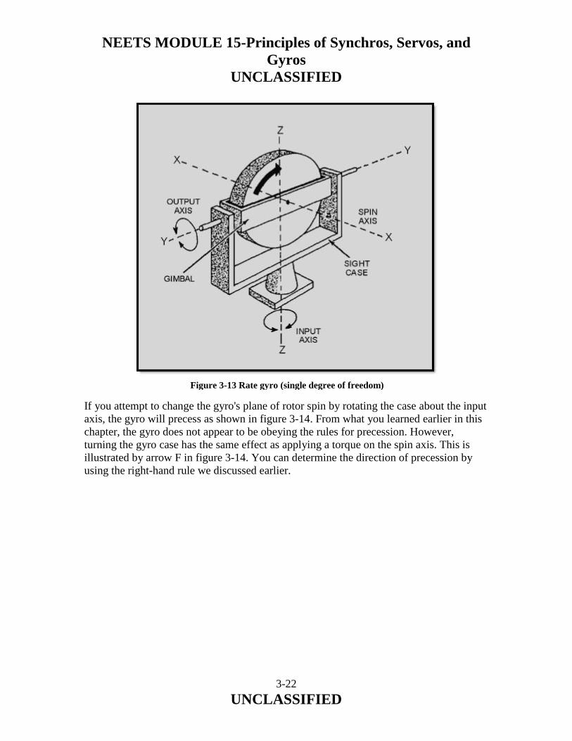
NEETS MODULE 15-Principles of Synchros, Servos, and Gyros
UNCLASSIFIED
3-22 UNCLASSIFIED
If you attempt to change the gyro's plane of rotor spin by rotating the case about the input axis, the gyro will precess as shown in figure 3-14. From what you learned earlier in this chapter, the gyro does not appear to be obeying the rules for precession. However, turning the gyro case has the same effect as applying a torque on the spin axis. This is illustrated by arrow F in figure 3-14. You can determine the direction of precession by using the right-hand rule we discussed earlier.
Figure 3-13 Rate gyro (single degree of freedom)

NEETS MODULE 15-Principles of Synchros, Servos, and Gyros
UNCLASSIFIED
3-23 UNCLASSIFIED
The force applied at F will cause the gyro to precess at right angles to the force. Likewise, attempting to turn the gyro case will cause the same result. The gyro will precess, as shown by the arrows, around the Y-Y axis (output axis). Since the rate of precession is proportional to the applied force, you can increase the precession by increasing the speed with which you are moving the gyro case. In other words, you have a rate gyro. The faster you turn the case, the more the gyro will precess, since the amount of precession is proportional to the rate at which you are turning the gyro case. This characteristic of a gyro, when properly used, fits the requirements needed to sense the rate of motion about any axis. Figure 3-15 shows a method of restraining the precession of a gyro to permit the calculation of an angle. Springs have been attached to the crossarm of the output shaft. These springs restrain the free precession of the gyro. The gyro may use other types of restraint, but no matter what type of restraint is used, the gyro is harnessed to produce some useful work.
Figure 3-14 Rate gyro precession

NEETS MODULE 15-Principles of Synchros, Servos, and Gyros
UNCLASSIFIED
3-24 UNCLASSIFIED
As the gyro precesses, it exerts a precessional force against the springs that is proportional to the momentum of the spinning wheel and the applied force. For example, suppose you rotate the gyro case (fig. 3-15) at a speed corresponding to a horizontal force of 2 pounds at F. Obviously, the gyro will precess; and as it does, it will cause the crossarm to pull up on spring A with a certain force, say 1 pound. (This amount of force would vary with the length of the crossarm.) If you continue to turn the gyro case at this rate, the precession of the gyro will continually exert a pull on the spring. More precisely, the gyro will precess until the 1 pound pull of the crossarm is exactly counterbalanced by the tension of the spring; it will remain in a fixed position, as shown in figure 3-15. That is, it will remain in the precessed position as long as you continue to rotate the gyro case at the same, constant speed. A pointer attached to the output axis could be used with a calibrated scale to measure precise angular rates.
Figure 3-15 Precession of a spring restrained rate gyro

NEETS MODULE 15-Principles of Synchros, Servos, and Gyros
UNCLASSIFIED
3-25 UNCLASSIFIED
When you stop moving the case, you remove the force at F, and the gyro stops precessing. The spring is still exerting a pull, however, so it pulls the crossarm back to the neutral position and returns the pointer to "zero." Suppose you now rotate the gyro case at a speed twice as fast as before, and in the same direction. This will be equal to a 4-pound force applied at F and a resulting 2-pound pull by the crossarm on spring A. In this situation the gyro will precess twice as far before the tension on the restraining spring equals the pull on the crossarm. Precession increases when the rate of rotation increases, as shown in figure 3-16. Another type of rate gyro (often used in inertial navigation equipment) is the floated gyro unit. This unit generally uses a restraint known as a torsion bar. The advantage of the torsion bar over the spring is that the torsion bar needs no lever arm to exert torque. The torsion bar is mounted along the output axis (fig. 3-17), and produces restraining torque in either direction by twisting instead of pulling. Also, there is no gimbal bearing friction to cause interference with gyro operation.
Figure 3-16 Precession is proportional to the rate of rotation

NEETS MODULE 15-Principles of Synchros, Servos, and Gyros
UNCLASSIFIED
3-26 UNCLASSIFIED
A fluid surrounds the gyro sphere and provides flotation. It also provides protection from shock, and damps the oscillations resulting from sudden changes in the angular rate input. In this gyro, the inner gimbal displacement must be measured with some type of electrical pickoff. As the gyro case is rotated about the input axis, clockwise or counterclockwise, a precession torque will be developed about the output axis that will cause the inner gimbal to exert torque against the torsion bars. The torsion bars provide a restraining torque proportional to the amount of the inner gimbal's displacement. When the exerted gimbal torque is exactly opposed by the restraining torque provided by the torsion bars, the inner gimbal displacement will be proportional to the rate of rotation of the gyro case about the input axis. The pickoff measures this displacement and provides a signal whose amplitude and polarity (or phase) represent the direction and magnitude of the input angular velocity. The important point to remember is that every "rate" gyro measures the RATE OF ROTATION ABOUT ITS INPUT AXIS. Up to this point, we have illustrated only basic gyros. We used these basic, or simple, gyros to explain their principles of operation In actuality, the rate gyros used in typical modern day weapon systems are considerably more complex, and in some cases, very compact. Figure 3-18 shows a cutaway view of a rate gyro used in our Navy's missile systems and aircraft.
Figure 3-17 Torsion bar-restrained floated rate gyro

NEETS MODULE 15-Principles of Synchros, Servos, and Gyros
UNCLASSIFIED
3-27 UNCLASSIFIED
Q-18. What are rate gyros primarily used for?
Q-19. How many degrees-of-freedom does a rate gyro usually have?
Q-20. What gyro characteristic provides the basis of the operation of a rate gyro?
Figure 3-18 Rate gyro, cutaway view

NEETS MODULE 15-Principles of Synchros, Servos, and Gyros
UNCLASSIFIED
3-28 UNCLASSIFIED
3.8 ACCELEROMETERS
An accelerometer is a device that gives an indication, usually in the form of a voltage, that is proportional to the acceleration to which it is subjected. The operation of an accelerometer is based on the property of INERTIA (Newton's First Law of Motion). A simple demonstration of inertia happens to us almost every day. You know that if your automobile is subjected to acceleration in a forward direction, you are forced back in the seat. If your auto comes to a sudden stop, you are drawn forward. When your auto goes into a turn, you tend to be forced away from the direction of the turn-that is, if your auto turns left, you are forced to the right, and vice versa. If we replace the human in an auto with a mass suspended in an elastic mounting system, as shown in figure 3-19, any acceleration of the auto will cause movement of the mass relative to the auto. The amount of displacement is proportional to the force causing the acceleration. The direction the mass moves is always opposite to the direction of the auto's acceleration. The mass moves according to Newton's second Law of Motion which states: when a body is acted on by force, its resulting acceleration is directly proportional to the force and inversely proportional to the mass of the body. When no acceleration is present, the mass will be at rest. When acceleration is present, the mass will lag in proportion to the acceleration force. In other words, the car moves but the mass wants to remain at rest. Accelerometers are used principally in inertial navigation systems. They are used in aircraft and missile navigation systems as well as aboard ship. Some common types of accelerometers are described briefly in the following paragraphs.
Figure 3-19 Auto with spring-suspended now

NEETS MODULE 15-Principles of Synchros, Servos, and Gyros
UNCLASSIFIED
3-29 UNCLASSIFIED
3.8.1 The Basic Accelerometer
Figure 3-20 is a simplified drawing of a basic accelerometer. It consists of a mass that is free to slide along the sensitive axis within the case. The movement of the mass is limited by the springs. When the case is accelerated, the mass, because of its inertia, tends to remain stationary. This results in a relative movement of the mass with respect to the case. When the stretch of the springs overcomes the inertia of the mass, the springs cause the mass to stop moving with respect to the case. The displacement of the mass with respect to the case is directly proportional to the acceleration of the case. When the case stops accelerating, the springs return the mass to its zero position (the reference position). To keep the springs from causing the mass to overshoot and oscillate about the reference position, some form of damping is needed. This is usually provided by an oil-filled case with vanes for oil to bypass the mass. An accelerometer is sensitive to gravity when its sensing axis is positioned so gravity can move or attempt to move the mass. This is useful in that we can use gravity as a reference for testing purposes, but it can be a serious problem because of the errors it may cause in acceleration measurements. If the unit is placed with the sensing axis vertical, the mass will be displaced such that the output is one "G," or one unit of gravity. This is done during testing. Then when the sensitive axis is turned so it is horizontal to the Earth, the springs center the mass, and the output of the unit is zero.
Figure 3-20 The basic accelerometer

NEETS MODULE 15-Principles of Synchros, Servos, and Gyros
UNCLASSIFIED
3-30 UNCLASSIFIED
3.8.2 E-Transformer Accelerometer
The E-transformer accelerometer (fig. 3-21) consists of a mass suspended from a calibrated leaf spring in a manner similar to a pendulum. The mass is effectively the armature of an E-transformer of the type used as an error detector in a servo system. The mass of the accelerometer is enclosed within a case that is filled with a damping liquid, which helps keep the pendulum from oscillating. The accelerometer is mounted so that acceleration in only the desired geometrical plane is detected. Refer to figure 3-21. Notice that when there is no acceleration, the pendulum remains centered and the accelerometer output is zero. However, when there is acceleration the mass or pendulum swings in the direction opposite to that of the acceleration, causing an output from the E-transformer. Since the amplitude of the pendulum's swing is proportional to the amplitude of the acceleration to which it is subjected, the output of the device indicates both the direction and amplitude of the acceleration. This output is within the limits of the equipment and is limited by physical stops.
Figure 3-21 E-transformer accelerometer

NEETS MODULE 15-Principles of Synchros, Servos, and Gyros
UNCLASSIFIED
3-31 UNCLASSIFIED
3.8.3 Pulse-Counting Accelerometer
The outputs of the accelerometers discussed so far are voltages, which are proportional to acceleration. These voltages are assigned scale factors (such as units per volt). The voltage represents the quantity. In many applications there is need for accelerometer output signals to be in digital form, which means that the signal consists of a series of pulses that indicates an actual number. Pulse counting accelerometers satisfy this need. Their pulse output can be supplied directly to computer circuits and other digital logic equipment. A schematic and a pictorial diagram of a pulse counting accelerometer is shown in figure 3-22, view (A) and view (B).
Figure 3-22A Pulse counting accelerometer

NEETS MODULE 15-Principles of Synchros, Servos, and Gyros
UNCLASSIFIED
3-32 UNCLASSIFIED
When velocity remains constant, the brush spring holds the mass at null, and the brush rests on the reset contact of the switch. As acceleration occurs, the tendency of the mass to remain at a constant velocity causes the spring to compress. As the spring compresses, it allows the brush to move off the reset contact. If the acceleration is great enough, the brush will pass over the switch contacts for acceleration levels 1, 2, 3, and 4. These levels are determined by the stiffness of the spring. As the brush passes over each contact (in a positive direction), an output pulse from each contact is coupled to one of four counters. This advances the counter one-half count. The accelerometer is designed so that as acceleration decreases, the mass tends to assume the new velocity. The counters will not advance the remaining half count until the brush once again touches the reset contact. With this type of pulse output, it is possible to record each time gravity forces have reached a predetermined level. Q-21. Operation of an accelerometer is based on what physical property?
Q-22. What type of systems primarily use accelerometers?
Q-23. What special requirement is the pulse counting accelerometer designed for?
Figure 3-22B.—Pulse counting accelerometer
NEETS MODULE 15-Principles of Synchros, Servos, and Gyros
UNCLASSIFIED
3-33 UNCLASSIFIED
3.9 SUMMARY
In this chapter you were introduced to the subject of gyros. You studied the characteristics of gyros and several applications of their use. You were also briefly introduced to the subject of accelerometers. The following information provides a summary of the chapter. The term GYROSCOPE (or GYRO) may be applied to any rapidly spinning object; however, a functional gyroscope is constructed and mounted to take advantage of certain characteristics. RIGIDITY in a gyro is the tendency of a spinning wheel (rotor) to remain in a fixed position in space. PRECESSION is the property of a gyro that causes it to tilt in a direction perpendicular to the direction of any outside force. The COMPONENTS OF A UNIVERSALLY MOUNTED GYRO are: the Rotor, the Inner Gimbal, the Outer Gimbal, and the Base. The FACTORS THAT EFFECT RIGIDITY are the weight, shape, and speed of rotation of the rotor. The DIRECTION OF PRECESSION in a gyro is always 90º from the direction of the applied force. A GYRO ERECTION SYSTEM must be capable of sensing the difference between the present rotor position and the desired rotor position, and must apply forces that will cause the gyro to precess toward the desired position. The mercury erection system discussed in this chapter is only one of several possible types of gyro erection systems. RATE GYROS are specially mounted so they are free to precess in only one direction; they are used to measure angular rates. An ACCELEROMETER is a device used to detect and measure any acceleration along a particular axis.

NEETS MODULE 15-Principles of Synchros, Servos, and Gyros
UNCLASSIFIED
3-34 UNCLASSIFIED
ANSWERS TO QUESTIONS Q1. THROUGH Q23.
A-1. Yes. A-2. X-axis. A-3. Rigidity. A-4. Any force that attempts to tilt the spin axis. A-5. Perpendicular (90º) to the force. A-6. Two. A-7. Rotor speed, weight, shape. A-8. C. A-9. Force of translation. A-10. Rigidity. A-11. Direction of spin. A-12. Middle finger. A-13. Two. A-14. Horizontal. A-15. Unbalanced gyro, inertia of gimbals, bearing friction. A-16. To achieve and maintain the proper operating position for the gyro (usually
vertical or horizontal). A-17. Applies torque at the proper point for correct precession. A-18. Measuring angular rates. A-19. One.

NEETS MODULE 15-Principles of Synchros, Servos, and Gyros
UNCLASSIFIED
3-35 UNCLASSIFIED
A-20. Precession. A-21. Inertia. A-22. Navigation systems. A-23. When digital data is required from an accelerometer.

NEETS MODULE 15-Principles of Synchros, Servos, and Gyros
UNCLASSIFIED
4-1 UNCLASSIFIED
4 RELATED DEVICES
LEARNING OBJECTIVES
After you finish this chapter, you should be able to do the following: 1. Compare standard synchro system connections with IC synchro connections. 2. Describe the operation of a step transmitter and receiver, and list the advantages
and disadvantages of a step-transmission system. 3. Compare the construction and operation of a resolver to those of a transformer,
describe the solution of resolution and composition problems by a resolver. 4.1 INTRODUCTION
Some other devices that logically should be included in this module are the IC synchros, step motors, and resolvers. These are all electromagnetic devices used in various shipboard and aircraft applications. They can be considered as second cousins of the synchro. 4.2 IC SYNCHROS
The engine order telegraph, steering telegraph, rudder-angle indicator, and similar position indicating systems used on naval ships are usually simple synchro systems. Some ships, however, use IC synchros to transfer such information. These units operate on the same general principle as the synchros we discussed in chapter 1. The interior communication synchro (IC synchro) is gradually being phased out and replaced by standard synchros when replacement is required. However, you will still find some IC synchros in use today. For that reason, you will find some background information on their purpose and theory to be beneficial. We will present these synchros in very basic form in the following paragraphs. Because of their construction, IC synchros are sometimes called reversed synchros. The primary winding, consisting of two series-connected coils, is mounted physically on the stator. The secondary, consisting of three Y-connected coils, is mounted physically on the rotor. This is shown schematically in figure 4-1.

NEETS MODULE 15-Principles of Synchros, Servos, and Gyros
UNCLASSIFIED
4-2 UNCLASSIFIED
IC synchros operate on the same principles of interacting magnetic fields as other synchros, but differ in direction of shaft rotation and amount of torque obtainable. When an IC transmitter and IC receiver are connected in parallel as shown in view A of figure 4-2, the shaft of the IC receiver follows the rotation of the IC transmitter shaft. In view B, the IC transmitter is replaced by a synchro transmitter; the IC receiver shaft now turns in a direction opposite to that of the synchro transmitter. Voltages that cause counterclockwise rotation of a standard synchro shaft cause clockwise rotation of an IC synchro shaft. When it is desirable to have the IC synchro receiver turn in an opposite direction from that of the transmitter, the connections are as shown in view C. For a standard synchro receiver to follow the rotation of an IC transmitter, their connections must be made as shown in view D.
Figure 4-1 IC synchro schematic diagrams

NEETS MODULE 15-Principles of Synchros, Servos, and Gyros
UNCLASSIFIED
4-3 UNCLASSIFIED
Figure 4-2A IC versus standard synchro connections
Figure 4-2B.—IC versus standard synchro connections
Figure 4-2C.—IC versus standard synchro connections

NEETS MODULE 15-Principles of Synchros, Servos, and Gyros
UNCLASSIFIED
4-4 UNCLASSIFIED
The torque obtainable from either an IC synchro or a standard synchro is determined by the magnetizing power, which is limited by the allowable temperature rise. When the stator is energized, as in IC synchros, the magnetizing power can be increased with a resulting larger torque. The reason for this is that the losses are dissipated in the form of heat around the outer shell of the IC transmitter or receiver. In standard synchros, this heat loss is dissipated through the rotor, the air gap, and then the outer shell to the surrounding air. The electrical zero position for an IC synchro is the position where rotor coil R2 is aligned with the stator as shown in figure 4-1. To zero an IC synchro, apply the same general theory as we described for other synchros. For further information on IC synchro replacement, alignment, and theory, refer to Military Handbook, Synchros, Description and Operation, (MIL-HDBK-225A). Q-1. What two characteristics of IC synchros cause them to differ from standard synchros?
Figure 4-2D.—IC versus standard synchro connections
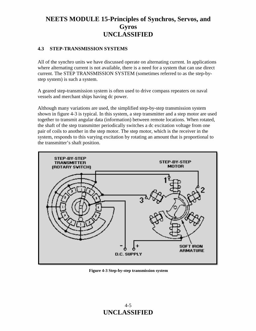
NEETS MODULE 15-Principles of Synchros, Servos, and Gyros
UNCLASSIFIED
4-5 UNCLASSIFIED
4.3 STEP-TRANSMISSION SYSTEMS
All of the synchro units we have discussed operate on alternating current. In applications where alternating current is not available, there is a need for a system that can use direct current. The STEP TRANSMISSION SYSTEM (sometimes referred to as the step-by-step system) is such a system. A geared step-transmission system is often used to drive compass repeaters on naval vessels and merchant ships having dc power. Although many variations are used, the simplified step-by-step transmission system shown in figure 4-3 is typical. In this system, a step transmitter and a step motor are used together to transmit angular data (information) between remote locations. When rotated, the shaft of the step transmitter periodically switches a dc excitation voltage from one pair of coils to another in the step motor. The step motor, which is the receiver in the system, responds to this varying excitation by rotating an amount that is proportional to the transmitter’s shaft position.
Figure 4-3 Step-by-step transmission system

NEETS MODULE 15-Principles of Synchros, Servos, and Gyros
UNCLASSIFIED
4-6 UNCLASSIFIED
The stator of this step motor has six field coils spaced 60 degrees apart. The coils are connected in three groups of two coils each, with opposite coils connected in series. One end of each pair of coils is connected to one of the brushes in the step transmitter. The other ends of the coils are connected to the other side of the dc supply voltage through a common lead. As the rotor of the step transmitter is turned, the corresponding coils in the step motor are energized in sequence, producing a rotating step-by-step stator field. Thus, the motor rotates in abrupt increments or steps rather than smoothly. NOTE: The theory of the step-by-step motor is similar to that involved in positioning the bar magnet (chapter 1, fig. 1-10). For ease of explanation, we will replace the step transmitter with a battery as we discuss the operation of the step motor. If, as shown in view A of figure 4-4, we apply the dc battery voltage across the number 1 coils only, the armature will turn to the position shown. When we apply the voltage also to the number 2 coils, the armature turns to a position midway between the number 1 and number 2 coils, view B. If we now disconnect the number 1 coils, the armature turns until it lines up with the number 2 coils, view C. View D shows the number 2 and 3 coils connected and the armature rotated one step further. As long as this process is continued, the armature can be rotated through 360 degrees.
Figure 4-4A Step-by-step motor in various positions. VOLTAGE APPLIED TO NUMBER 1 COILS ONLY

NEETS MODULE 15-Principles of Synchros, Servos, and Gyros
UNCLASSIFIED
4-7 UNCLASSIFIED
Figure 4-4B.—Step-by-step motor in various positions. VOLTAGE APPLIED TO NUMBER 1 AND NUMBER 2
Figure 4-4C.—Step-by-step motor in various positions. VOLTAGE APPLIED TO NUMBER 2 COILS ONLY
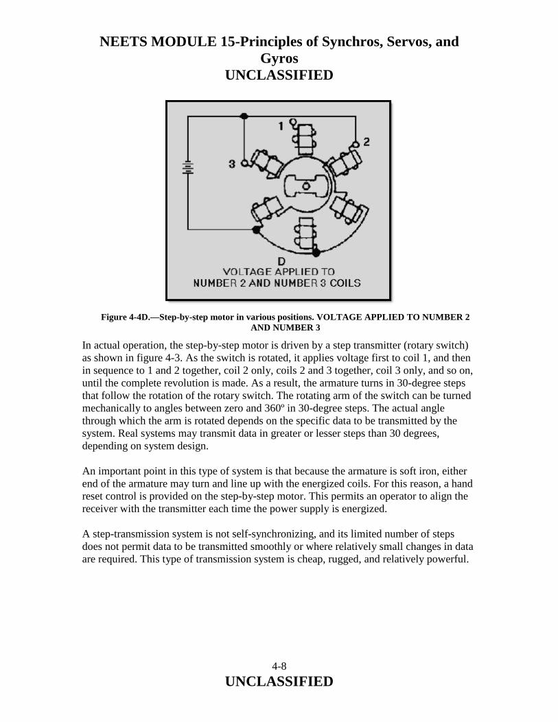
NEETS MODULE 15-Principles of Synchros, Servos, and Gyros
UNCLASSIFIED
4-8 UNCLASSIFIED
In actual operation, the step-by-step motor is driven by a step transmitter (rotary switch) as shown in figure 4-3. As the switch is rotated, it applies voltage first to coil 1, and then in sequence to 1 and 2 together, coil 2 only, coils 2 and 3 together, coil 3 only, and so on, until the complete revolution is made. As a result, the armature turns in 30-degree steps that follow the rotation of the rotary switch. The rotating arm of the switch can be turned mechanically to angles between zero and 360º in 30-degree steps. The actual angle through which the arm is rotated depends on the specific data to be transmitted by the system. Real systems may transmit data in greater or lesser steps than 30 degrees, depending on system design. An important point in this type of system is that because the armature is soft iron, either end of the armature may turn and line up with the energized coils. For this reason, a hand reset control is provided on the step-by-step motor. This permits an operator to align the receiver with the transmitter each time the power supply is energized. A step-transmission system is not self-synchronizing, and its limited number of steps does not permit data to be transmitted smoothly or where relatively small changes in data are required. This type of transmission system is cheap, rugged, and relatively powerful.
Figure 4-4D.—Step-by-step motor in various positions. VOLTAGE APPLIED TO NUMBER 2 AND NUMBER 3
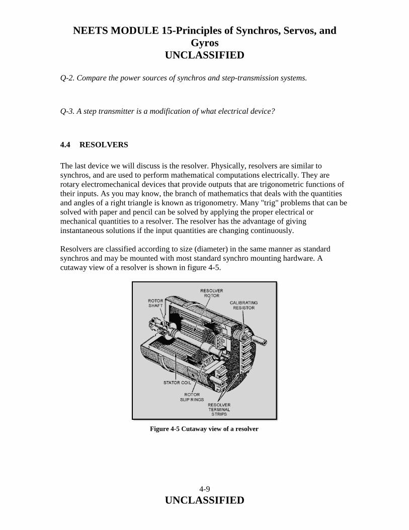
NEETS MODULE 15-Principles of Synchros, Servos, and Gyros
UNCLASSIFIED
4-9 UNCLASSIFIED
Q-2. Compare the power sources of synchros and step-transmission systems.
Q-3. A step transmitter is a modification of what electrical device?
4.4 RESOLVERS
The last device we will discuss is the resolver. Physically, resolvers are similar to synchros, and are used to perform mathematical computations electrically. They are rotary electromechanical devices that provide outputs that are trigonometric functions of their inputs. As you may know, the branch of mathematics that deals with the quantities and angles of a right triangle is known as trigonometry. Many "trig" problems that can be solved with paper and pencil can be solved by applying the proper electrical or mechanical quantities to a resolver. The resolver has the advantage of giving instantaneous solutions if the input quantities are changing continuously. Resolvers are classified according to size (diameter) in the same manner as standard synchros and may be mounted with most standard synchro mounting hardware. A cutaway view of a resolver is shown in figure 4-5.
Figure 4-5 Cutaway view of a resolver

NEETS MODULE 15-Principles of Synchros, Servos, and Gyros
UNCLASSIFIED
4-10 UNCLASSIFIED
Notice that the stator of the resolver is a cylindrical structure of slotted laminations on which two coils are wound. The rotor is composed of a shaft, laminations, two windings, and four slip rings. Compensator components, which improve the angular accuracy of resolvers, may consist of resistors or additional windings in the stator and rotor winding circuits. Compensator windings, which increase the accuracy of the resolver, are located inside the stator. Compensating (calibrating) resistors, which compensate for voltage inaccuracies and phase shifts, may be mounted either inside or outside the resolver housing. A cylindrical frame with a standardized mounting flange houses the assembled resolver. External and internal connections can be made to an insulated terminal board on the rear of the housing. Miniature resolvers often have lead wires brought out through the rear of the resolver, eliminating the need for a terminal block. A reference line is scribed on the face of the housing for alignment with a similar line on the end of the rotor shaft. These are used in determining coarse electrical zero. Basically, a resolver is a transformer in which the secondary windings can be rotated with respect to the primary windings. Consequently, the amount of magnetic coupling between the primary and the secondary is variable. In the most common form, a resolver consists of a stator and a rotor, each having two separate windings placed precisely at right angles to each other as shown in figure 4-6.
Figure 4-6 Resolver schematic

NEETS MODULE 15-Principles of Synchros, Servos, and Gyros
UNCLASSIFIED
4-11 UNCLASSIFIED
Since the two stator windings are physically and electrically at right angles to each other, there is no magnetic coupling between them. The stator windings are mounted on the resolver housing and are stationary with respect to it. Similarly, the rotor windings of the resolver are wound at right angles to each other. Hence, there is no magnetic coupling between the two windings. The rotor windings are mounted on the rotor shaft and turn with it. The rotor is capable of unlimited rotation. Thus, the rotor windings can be set at any angle with respect to the stator windings. Because of the 90º physical and electrical relationships, the resolver has the ability to separate a quantity into its two right-angle components. This is called RESOLUTION. Figure 4-7 illustrates the use of a resolver in solving a resolution problem. Assume that a voltage, E, and an angle, R, represent the magnitude and direction of a known quantity. To determine the two right angle components of the quantity, feed the magnitude of the quantity to one stator coil and physically turn the rotor through angle R. The input voltage (E) induces voltage E1 and E2 in the two rotor coils. The values of these rotor voltages represent the vertical and horizontal components of the known quantity and depend on both the value of E and the angle (R) through which the rotor was turned.
Figure 4-7 One example of resolution

NEETS MODULE 15-Principles of Synchros, Servos, and Gyros
UNCLASSIFIED
4-12 UNCLASSIFIED
Similarly, the resolver has the ability to add two vectors that are at right angles to each other and produce the resultant vector (hypotenuse) at the resultant angle. This is called COMPOSITION. Figure 4-8 illustrates one use of a resolver in solving a composition problem. Assume that we have two known quantities, vertical and horizontal components, that are represented by E1 and E2, respectively. Each of these is fed to a stator coil. These two voltages induce a voltage, ET, in one of the rotor coils. ET represents a voltage that is proportional to the hypotenuse. The voltage induced in the other rotor coils is fed to a closed-loop servo, which positions the rotor shaft to the angle (direction) of the hypotenuse. Other mathematical solutions are possible to designers who apply resolvers in equipment. Typical naval problems solved by resolvers involve distances, speeds, angular quantities, etc. In most cases, as in figures 4-7 and 4-8, only resolver coils actively used in solving a particular problem are shown in schematics. Resolvers can also perform a third function COMBINATION. This is the process of resolution and composition taking place simultaneously.
Figure 4-8 One example of composition

NEETS MODULE 15-Principles of Synchros, Servos, and Gyros
UNCLASSIFIED
4-13 UNCLASSIFIED
The resolver is a precision component, whose electrical characteristics are critical, and any deviation may result in excessive errors in the system. Before working on or replacing resolvers, you should check the associated equipment technical manual. Q-4. What type of mathematical problem is solved by resolvers?
4.5 SUMMARY
The following are brief summaries of the IC SYNCHROS, STEP-TRANSMISSION SYSTEMS, and RESOLVERS we covered in this chapter. IC SYNCHROS, sometimes referred to as reversed synchros, are used in systems where transfer of information is desired. They operate on the same principles as synchros but differ in the direction of shaft rotation and amount of torque obtained. A STEP-TRANSMISSION SYSTEM (STEP-BY-STEP SYSTEM) is similar to a synchro system, except that it is energized by direct current. This system uses a rotary switch to transfer angular data (information) between remote locations. The system is cheap, rugged, relatively powerful, but is not used where small changes in data are required. RESOLVERS are physically similar to synchros and are used to perform mathematical computations. They are used extensively in analog computers, radar sets, direction and target designation equipment.

NEETS MODULE 15-Principles of Synchros, Servos, and Gyros
UNCLASSIFIED
4-14 UNCLASSIFIED
ANSWERS TO QUESTIONS Q1. THROUGH Q4.
A-1. Direction of rotation and amount of torque. A-2. Synchros use ac; step transmission uses dc. A-3. Rotary switch. A-4. Right-triangle, or trigonometric, problems.

NEETS MODULE 15-Principles of Synchros, Servos, and Gyros
UNCLASSIFIED
A-1 UNCLASSIFIED
APPENDIX A
GLOSSARY
ACCELERATION SERVO SYSTEM—A servo system that controls the acceleration (rate of change in velocity) of a load. ACCELEROMETER—A device that measures acceleration to which it is subjected and develops a signal proportional to it. ANGULAR POSITION—The counterclockwise angular displacement of a synchro rotor, measured in degrees from its electrical zero position, as viewed from the shaft extension end of the synchro. APPARENT DRIFT—The effect of the Earth's rotation on a gyro, which causes the spinning axis to appear to make one complete rotation in one day. Also called APPARENT PRECESSION or APPARENT ROTATION. APPARENT PRECESSION—See apparent drift. APPARENT ROTATION—See apparent drift. AXIS—A straight line, either real or imaginary, passing through a body, around which the body revolves. BANDWIDTH—The range of frequencies a servo amplifier can amplify without causing unacceptable distortion to the input signal. CONTROL DIFFERENTIAL TRANSMITTER (CDX)—A type of synchro that transmits angular information equal to the algebraic sum or difference of the electrical input supplied to its stator, and the mechanical input supplied to its rotor. The output is an electrical voltage taken from the rotor windings. CONTROL SYNCHRO SYSTEMS—Synchro systems that contain control synchros and are used to control large amounts of power with a high degree of accuracy. The electrical outputs of these systems control servo systems, which in turn generate the required power to move heavy loads. CONTROL SYSTEM—A group of components, systematically organized to perform a specific control purpose. These systems are categorized as either closed- or open-loop systems. The main difference between the two is that the closed-loop system contains some form of feedback.

NEETS MODULE 15-Principles of Synchros, Servos, and Gyros
UNCLASSIFIED
A-2 UNCLASSIFIED
CONTROL TRANSFORMER (CT)—A type of synchro that compares two signals: the electrical signal applied to its stator and the mechanical signal applied to its rotor. The output is an electrical voltage, which is taken from the rotor winding and is used to control a power amplifying device. The phase and amplitude of the output voltage depend on the angular position of the rotor with respect to the magnetic field of the stator. CONTROL TRANSMITTER (CX)—A type of synchro that converts a mechanical input, which is the angular position of its rotor, into an electrical output signal. The output is taken from the stator windings and is used to drive either a CDX or CT. CORRESPONDENCE—The term given to the positions of the rotors of a synchro transmitter and a synchro receiver when both rotors are on 0 or displaced from 0 by the same angle. DAMPING—A mechanical or electrical technique used in synchro receivers to prevent the rotor from oscillating or spinning. Damping is also used in servo systems to minimize overshoot of the load. DATA TRANSMISSION—The transfer of information from one place to another or from one part of a system to another. DEGREE-OF-FREEDOM—The number of axes about which a gyro is free to precess. DEMODULATOR—A circuit used in servo systems to convert an ac signal to a dc signal. The magnitude of the dc output is determined by the magnitude of the ac input signal, and its polarity is determined by whether the ac input signal is in or out of phase with the ac reference voltage. DOUBLE RECEIVER—A fine and coarse synchro receiver enclosed in a common housing with a two-shaft output (one shaft inside the other). E-TRANSFORMER—A special form of differential transformer using an E-shaped core. The secondaries of the transformer are wound on the outer legs of the E, and the primary is on the center leg. An output voltage is developed across the secondary coils when its armature is displaced from its neutral position. This device is used as an error detector in servo systems that have limited load movements. ELECTRICAL-LOCK—A synchro zeroing method. This method is used only when the rotors of the synchros to be zeroed are free to turn and their leads are accessible. ELECTRICAL ZERO—A standard synchro position, with a definite set of stator voltages, that is used as the reference point for alignment of all synchro units. ERECTING (A GYRO)—The positioning of a gyro into a desired position and the maintaining of that position.

NEETS MODULE 15-Principles of Synchros, Servos, and Gyros
UNCLASSIFIED
A-3 UNCLASSIFIED
ERROR DETECTOR—The component in a servo system that determines when the load has deviated from its ordered position, velocity, etc. ERROR REDUCER—The name commonly given to the servo motor in a servo system. So named because it reduces the error signal by providing feedback to the error detector. ERROR SIGNAL—In servo systems, the signal whose amplitude and polarity or phase are used to correct the alignment between the controlling and the controlled element. It is also the name given to the electrical output of a control transformer (CT). EXCITATION VOLTAGE—The supply voltage required to excite a circuit. FREQUENCY RESPONSE—The measure of a servo's ability to respond to various input frequencies. GIMBAL—A mechanical frame, with two perpendicular, intersecting axes of rotation, used to support and furnish a gyro wheel with the necessary freedom to tilt in any direction. GYRO—Abbreviation for gyroscope. GYROSCOPE—A mechanical device containing a spinning mass mounted so that it can assume any position in space. IC SYNCHROS—Electromechanical devices, used to transmit information, that operate on the same principles of interacting magnetic fields as synchros, but differ in their direction of rotation and the amount of torque obtainable. Because of their construction, they are sometimes called reversed synchros. INERTIA—The physical tendency of a body in motion to remain in motion and a body at rest to remain at rest unless acted upon by an outside force (Newton's First Law of Motion). MAGNETIC AMPLIFIER—An electromagnetic device that uses one or more saturable reactors to obtain a large power gain. This device is used in servo systems requiring large amounts of power to move heavy loads. MILITARY STANDARD SYNCHROS—Synchros that conform to specifications that are uniform throughout the Armed Services. MODULATOR—A circuit used in servo systems to convert a dc signal to an ac signal. The output ac signal is a sine wave at the frequency of the ac reference voltage. The amplitude of the output is directly related to the amplitude of the dc input. The circuit's function is opposite to that of a DEMODULATOR. MULTI-LOOP SERVO SYSTEM—A servo system that contains more than one servo loop, each loop designed to perform its own function.

NEETS MODULE 15-Principles of Synchros, Servos, and Gyros
UNCLASSIFIED
A-4 UNCLASSIFIED
MULTISPEED SYNCHRO SYSTEMS—Systems that transmit data at different transmission speeds; for example, dual-speed and tri-speed synchro systems. NEWTON’S SECOND LAW OF MOTION—If an unbalanced outside force acts on a body, the resulting acceleration is directly proportional to the magnitude of the force, is in the direction of the force, and is inversely proportional to the mass of the body. POSITION SENSOR—A component in a servo system that measures position and converts the measurement into a form convenient for transmission as a feedback signal. POSITION SERVO SYSTEM—A servo system whose end function is to control the position of the load it is driving. POTENTIOMETER—An electromechanical device, used as a position sensor in servo systems, having a terminal connected to each end of a restrictive element, and a third connected to a wiper contact. The output is a voltage that is variable depending upon the position of the wiper contact. The potentiometer is commonly referred to as a variable voltage divider. It, in effect, converts mechanical information into an electrical signal. PRECESSION—The rotation of the spin axis of a gyro in response to an applied force. The direction of precession is always perpendicular to the direction of applied force. PRECESSION VECTOR—In a gyro, a vector representing the angular change of the spin axis when torque is applied. The precession vector represents the axis about which precession occurs. PRESTANDARD NAVY SYNCHROS—Synchros that are designed to meet Navy, rather than servicewide, specifications. RATE GYRO—A gyro used to detect and measure angular rates of change. RESOLVER—A rotary, electromechanical device used to perform trigonometric computations by varying the magnetic couplings between its primary and secondary windings. It is generally used in circuits that solve vector problems, such as analog computers and conversion equipment. The resolver solves three different type problems: (1) resolution—separating a vector into two mutually perpendicular components; (2) composition—combining two components of a vector to produce a vector sum; (3) combination—the process of resolution and composition taking place simultaneously. RESULTANT MAGNETIC FIELD—The magnetic field produced in a synchro by the combined effects of the three stator magnetic fields. RIGIDITY—The tendency of the spin axis of a gyro wheel to remain in a fixed direction in space if no force is applied to it.

NEETS MODULE 15-Principles of Synchros, Servos, and Gyros
UNCLASSIFIED
A-5 UNCLASSIFIED
ROTOR—The rotating member of a synchro that consists of one or more coils of wire wound on a laminated core. Depending on the type of synchro, the rotor functions similar to the primary or secondary winding of a transformer. In a gyro, the rotating member is sometimes called a gyro wheel. SCALING FACTOR—The term used to describe the use of unequal resistors in a servo's summing network to compensate for differences between input and output signal levels. SERVO AMPLIFIER—An ac or dc amplifier used in servo systems to build up signal strength. These amplifiers usually have relatively flat gain versus frequency response, minimum phase shift, low output impedance, and low noise level. The dc amplifier is subject to excessive drift and is relatively unstable. However, the ac amplifier is considered drift free and has a constant dynamic gain over a variety of operating points. SERVO MOTOR—An ac or dc motor used in servo systems to move a load to a desired position or at a desired speed. The ac motor is usually used to drive light loads at a constant speed, while the dc motor is used to drive heavy loads at varying speeds. SERVO SYSTEM—An automatic feedback control system that compares a required condition (desired value, position, etc.) with an actual condition and uses the difference to adjust a control device to achieve the required condition. SIGNAL—The angle through which a synchro transmitter rotor is mechanically turned. SPIN VECTOR—In a gyro, a vector representing the angular velocity of the gyro rotor. The spin vector lies along the spin axis of the rotor. STATOR—The stationary member of a synchro that consists of a cylindrical structure of slotted laminations on which three Y-connected coils are wound with their axes 120 apart. Depending on the type of synchro, the stator's functions are similar to the primary or secondary windings of a transformer. STEP-TRANSMISSION SYSTEM—A data transmission system that operates on direct current. It consists of a step transmitter (rotary switch) and a step motor interconnected to transmit data (information) between remote locations. STICKOFF VOLTAGE—A low voltage used in multispeed synchro systems to prevent false synchronizations. SUMMING NETWORK—A combination of two or more parallel resistors used in servo systems as error detectors. The output of the network is the algebraic sum of the inputs. SYNCHRO—A small motor-like device that operates like a variable transformer and is used primarily for the rapid and accurate transmission of data among equipments and stations.

NEETS MODULE 15-Principles of Synchros, Servos, and Gyros
UNCLASSIFIED
A-6 UNCLASSIFIED
SYNCHRO CAPACITOR—A unit containing three delta-connected capacitors. The synchro capacitor is used in synchro systems to increase the system's accuracy by cancelling or reducing phase shift introduced by synchro inductance. SYNCHRO SYSTEM—Two or more synchros interconnected electrically. The system is used to transmit data among equipments and stations. SYNCHRO TESTER—A synchro receiver with a calibrated dial. This receiver is used primarily for locating defective synchros. It can also be used for zeroing synchros. SYNCHRO TROUBLESHOOTING—The locating or diagnosing of synchro malfunctions or breakdowns by means of systematic checking or analysis. SYNCHRONIZING NETWORK—A circuit used in servo systems, also called a crossover or switching network, to sense how far the load is from the point of correspondence and then functions to switch the appropriate signal into control. TACHOMETER—A small ac or dc generator, sometimes referred to as a rate generator, which converts its shaft speed into an electrical output. The tachometer is frequently used in servo systems to sense the velocity of a load. TIME LAG—The delay in a servo system between the application of the input signal and the actual movement of the load. TORQUE—A measure of how much load a machine can turn. This measurement is expressed either in ounce-inches for torque synchro systems or in pound-feet for heavy machinery. TORQUE DIFFERENTIAL RECEIVER (TDR)—A type of differential synchro that takes two electrical inputs, one to the rotor and one to the stator, and produces a mechanical output. The output is the angular position of the rotor, which represents the algebraic sum or difference of the two electrical inputs. TORQUE DIFFERENTIAL SYNCHRO SYSTEM—A synchro system containing either a TDX or a TDR. This system is used in application where it is necessary to compare two signals, add or subtract the signals, and furnish an output proportional to the sum or difference between the two signals. TORQUE DIFFERENTIAL TRANSMITTER (TDX)—A synchro that is functionally the same as the CDX except that it is used in torque systems rather than control systems. TORQUE RECEIVER (TR)—A type of synchro that converts the electrical input supplied to its stator back to a mechanical angular output through the movement of its rotor. TORQUE SYNCHRO SYSTEM—A synchro system that uses torque synchros to move light loads such as dials, pointers, and other similar devices.

NEETS MODULE 15-Principles of Synchros, Servos, and Gyros
UNCLASSIFIED
A-7 UNCLASSIFIED
TORQUE TRANSMITTER (TX)—A synchro that is functionally the same as the CX except that it is used in torque synchro systems. TORQUE VECTOR—In a gyro, a vector representing the rotary motion applied to change the direction of the rotor axis. The torque vector represents the axis about which the applied force is felt. TRANSLATION—In a gyro, a force acting through the center of gravity of the gyro that causes no torque on the gyro rotor. Translation forces do not change the angle of the plane of rotation but move the gyroscope as a unit. TROUBLE INDICATORS—Signal lights used to aid maintenance personnel in locating synchro troubles quickly. TROUBLE TABLES—Tables of trouble symptoms and probable causes furnished by many manufacturers, with their equipment, to help technicians isolate synchro problems. VELOCITY SERVO SYSTEM—A servo system that controls the speed of the load it is driving. X-AXIS—In a gyro, the spin axis of the gyro. Y-AXIS—In a gyro, an axis through the center of gravity and perpendicular to the spin axis. Z-AXIS—In a gyro, an axis through the center of gravity and mutually perpendicular to both the spin (X) and Y axes. ZEROING—The process of adjusting a synchro to its electrical zero position.

NEETS MODULE 15-Principles of Synchros, Servos, and Gyros
UNCLASSIFIED
1 UNCLASSIFIED
ASSIGNMENT 1
Textbook assignment: Chapter 1, “Synchros,” pages 1-1 through 1-91. 1-1. Which of the following terms accurately describes a synchro?
1. Position-sensing 2. Electromechanical 3. Rotary 4. Each of the above
1-2. What are the two general classifications of synchro systems?
1. Torque and load 2. Torque and control 3. Load and control 4. Load and lock
1-3. What is the difference in application between the two classifications of synchros?
1. Light versus heavy load 2. Mechanical versus electrical Output 3. Circular versus straight-line motion 4. High-frequency versus low-frequency operation
1-4. Which of the following types of synchro devices provides a mechanical output?
1. A control transformer 2. A torque receiver 3. A torque transmitter 4. A control transmitter
1-5. A 115-volt, 400-Hz torque transmitter with a diameter of 2.36 inches will have what
military standard designation code?
1. 115 V-23CT6 2. 115 V-24TT4 3. 23TD4 4. 24TX4

NEETS MODULE 15-Principles of Synchros, Servos, and Gyros
UNCLASSIFIED
2 UNCLASSIFIED
1-6. A 3.5-inch diameter differential receiver will have what Navy prestandard designation code?
1. 35CR 2. 35TDR 3. 5D 4. 5DG
1-7. What does the arrow on a synchro schematic symbol indicate?
1. The direction of current flow 2. The direction of rotor movement 3. The angular position of the stator 4. The angular position of the rotor
1-8. What are the two major components of a synchro?
1. The rotor and the stator 2. The housing and the stator 3. The rotor and the shaft 4. The housing and the shaft
1-9. What type of rotor can be composed of a single winding or three Y-connected windings?
1. Salient-pole 2. Drum or wound 3. Fixed 4. "H"
1-10. How does the stator of a TX receive voltage?
1. By a physical connection with the rotor 2. By a magnetic coupling with another stator 3. By a magnetic coupling with the rotor 4. By a physical connection with a source
1-11. What part of a synchro provides a point for external connections?
1. The terminal board 2. The slip ring 3. The stator 4. The brush

NEETS MODULE 15-Principles of Synchros, Servos, and Gyros
UNCLASSIFIED
3 UNCLASSIFIED
1-12. Which of the following terms is defined as the amount of load a machine can turn?
1. Radian force 2. Load factor 3. Torque 4. Tension
1-13. Which of the following units should be used in measuring the amount of turning force of
a synchro?
1. Ounces 2. Pounds 3. Foot-pounds 4. Ounce-inches
1-14. An overloaded synchro will probably exhibit which of the following conditions?
1. Overspeed 2. Oscillation 3. Excessive temperature 4. Noisy operation
1-15. A synchro receiver has which of the following characteristics that is NOT found in an
ordinary transformer?
1. A primary that can rotate in relation to the secondary 2. A primary magnetically coupled to the secondary 3. A step-up turns ratio 4. An air core
1-16. When a synchro transmitter is in the zero-degree position, the rotor is aligned in what
manner?
1. With winding S1 2. With winding S2 3. With winding S3 4. Between winding S1 and S2
1-17. Maximum voltage is induced in a stator winding of a synchro transmitter when the rotor
and the stator winding have what angle between them?
1. 0 degrees 2. 30 degrees 3. 60 degrees 4. 90 degrees

NEETS MODULE 15-Principles of Synchros, Servos, and Gyros
UNCLASSIFIED
4 UNCLASSIFIED
1-18. Which of the following factors does NOT affect the amplitude of the voltage induced in a stator winding of a synchro transmitter?
1. The angular displacement between the rotor and stator 2. The amplitude of the primary voltage 3. The speed of data transmission 4. The turns ratio of the synchro
1-19. Damping is necessary for which of the following synchro devices?
1. Receiver 2. Transmitter 3. Control transformer 4. Differential transmitter
1-20. The primary purpose of damping is to reduce which of the following conditions in a
synchro device?
1. Readings 180º out of phase 2. Overheating 3. Oscillating 4. Each of the above
1-21. What is the minimum number of synchro devices needed for a simple synchro
transmission system?
1. One 2. Two 3. Three 4. Four
1-22. In a simple synchro system, what leads are connected to the source voltage?
1. R1 and R2 2. S1 and S2 3. S2 and S3 4. R1 and S1
1-23. When a synchro transmitter, and receiver are in correspondence, what is the relative
value of the (a) current through the stators and (b) receiver torque?
1. (a) Maximum (b) maximum 2. (a) Maximum (b) minimum 3. (a) Minimum (b) minimum 4. (a) Minimum (b) maximum

NEETS MODULE 15-Principles of Synchros, Servos, and Gyros
UNCLASSIFIED
5 UNCLASSIFIED
1-24. What term applies to the angle through which a synchro transmitter rotor is rotated mechanically?
1. Lag 2. Lead 3. Gain 4. Signal
1-25. If a synchro receiver is required to rotate in a direction opposite to the rotation of the
transmitter rotor, what leads should be reversed?
1. R1 and R2 2. S1 and S2 3. S2 and S3 4. S1 and S3
1-26. If a synchro receiver and transmitter are always 180 degrees out of phase with each other,
what leads are reversed?
1. R1 and R2 2. S1 and S2 3. S2 and S3 4. S1 and S3
1-27. What type of synchro can accept two signals simultaneously and add or subtract?
1. Transmission 2. Differential 3. Automatic 4. Shiftless
1-28. What are the two types of synchro devices that will accept two inputs?
1. TR and TX 2. TR and TDX 3. TDR and TX 4. TDR and TDX
1-29. What types of synchro devices have (a) one electrical and one mechanical input and an
electrical output; and (b) two electrical inputs and a mechanical outputs?
1. (a) TR (b) TX 2. (a) TX (b) TR 3. (a) TDX (b) TDR 4. (a) TDR (b) TDX

NEETS MODULE 15-Principles of Synchros, Servos, and Gyros
UNCLASSIFIED
6 UNCLASSIFIED
1-30. What determines whether a differential synchro device adds or subtracts its inputs?
1. The way it is connected in the system 2. The direction of rotor movement 3. The number of stator windings 4. The supply voltage polarity
1-31. In a TDX system, for the TR rotor to follow the TX rotor exactly, in what position must
the TDX rotor be kept?
1. 0 degree position 2. 60 degree position 3. 120 degree position 4. 240 degree position
1-32. What is the angular position of a TR rotor when it is pointing to the S3 winding?
1. 0 degrees 2. 60 degrees 3. 120 degrees 4. 240 degrees
1-33. If a TDX system with standard synchro connections has the TX rotor at the 60- degree
position and the TDX rotor at the 270-degree position, what is the position of the TR rotor?
1. 110 degrees 2. 150 degrees 3. 210 degrees 4. 250 degrees
1-34. For a TDX system to add its inputs rather than subtract them, what leads must be
reversed between (a) the TX and TDX, and (b) the TR and TDX?
1. (a) S1 and S2 (b) R1 and R3 2. (a) S1 and S3 (b) R1 and R3 3. (a) S2 and S3 (b) R1 and R2 4. (a) S1 and S3 (b) R1 and R2
1-35. For a TDR system to add its inputs rather than subtract them, what leads must be reversed
at the TDR?
1. S1 and S3 2. S1 and S2 3. R1 and R3 4. R1 and R2

NEETS MODULE 15-Principles of Synchros, Servos, and Gyros
UNCLASSIFIED
7 UNCLASSIFIED
1-36. If a TDR system is connected for addition and the TX rotor connected to the TDR rotor turns counterclockwise, in what direction will the TDR rotor field rotate?
1. In a direction determined by the other TX stator 2. In a direction determined by the other TX rotor 3. Counterclockwise 4. Clockwise
1-37. Which of the following types of synchros is used in a system requiring large amounts of
power and high accuracy?
1. Torque 2. Control 3. Differential 4. Each of the above
1-38. What are the three types of control synchros?
1. TX, TR, CT 2. TX, CDX, CR 3. CX, CT, CR 4. CX, CT, CDX
1-39. The CX and CDX differ from the TX and TDX because the CX and CDX have which of
the following characteristics?
1. Lower impedance windings 2. Higher impedance windings 3. Larger physical size 4. Smaller physical size
1-40. Which of the following is NOT a characteristic of the rotor of a control transformer (CT)
rotor?
1. It is connected to a high-impedance load 2. It must be turned by an external force 3. It is connected to an ac source 4. It has a drum- or wound-type rotor
1-41. When a control transformer is at electrical zero, the rotor is perpendicular to what
winding?
1. S1 2. S2 3. S3 4. R2

NEETS MODULE 15-Principles of Synchros, Servos, and Gyros
UNCLASSIFIED
8 UNCLASSIFIED
1-42. If a control transformer is held at electrical zero and the control transmitter is turned 90 degrees counterclockwise, what is (a) the amplitude of the induced voltage in the rotor of the control transformer, and (b) the phase relationship of this voltage and the excitation voltage to the control transmitter?
1. (a) Maximum (b) out-of-phase 2. (a) Maximum (b) in phase 3. (a) Minimum (b) out-of-phase 4. (a) Minimum (b) in phase
1-43. Which of the following terms applies to the output of a control transformer?
1. Mechanical movement 2. Deflection angle 3. Output voltage 4. Error signal
1-44. If the output of a control transformer is zero, what is the relationship of the rotors of the
control transformer and the control transmitters?
1. In correlation 2. Out of correlation 3. In correspondence 4. Out of correspondence
1-45. Synchro capacitors are used to provide which of the following characteristics in a
synchro system?
1. Improved accuracy 2. Reduced oscillations 3. Wider frequency response 4. Higher load-carrying capacity
1-46. Which of the following synchro devices uses a synchro capacitor?
1. TX 2. RX 3. TDR 4. CDX
1-47. What type of current is eliminated by synchro capacitors?
1. Loss 2. Rotor 3. Stator 4. Magnetizing Stator

NEETS MODULE 15-Principles of Synchros, Servos, and Gyros
UNCLASSIFIED
9 UNCLASSIFIED
1-48. In what configuration are synchro capacitors connected in a synchro circuit?
1. Wye, across the rotor windings 2. Delta, across the rotor windings 3. Wye, across the stator windings 4. Delta, across the stator windings
1-49. To maintain system accuracy, where are synchro capacitors physically placed in a
synchro circuit?
1. Close to the TX or RX 2. Close to the TDX, CDX, or CT 3. Midway between the TX and CT 4. Far away from the TDR, CDX, or CT
1-50. Synchro systems that transmit data at two different speeds are referred to by which of the
following terms?
1. Dual-speed 2. Two-speed 3. Twin-speed 4. Each of the above
1-51. Multispeed synchro systems have which of the following advantages over single speed
synchro systems?
1. Easier to troubleshoot and align 2. Fewer moving parts 3. Greater accuracy 4. All of the above
1-52. What does the gear ratio between the two transmitters in a dual-speed synchro system
determine?
1. The direction of transmitter-rotation 2. The direction of receiver rotation 3. The speeds of transmission 4. The relative direction of rotation
1-53. Which of the following synchro systems, if any, should be used to transmit very large
quantities?
1. Single-speed 2. Two-speed 3. Tri-speed 4. None of the above

NEETS MODULE 15-Principles of Synchros, Servos, and Gyros
UNCLASSIFIED
10 UNCLASSIFIED
1-54. Which of the following is a disadvantage of a double receiver as compared to two single receivers?
1. The entire unit must be replaced if one portion fails 2. It takes up much more space 3. It is much more costly 4. It is much heavier
1-55. The voltage used to prevent false synchronizations is known by what term?
1. Error voltage 2. Signal voltage 3. Source voltage 4. Stickoff voltage
1-56. What is the reference point for the alignment of all synchro units?
1. Mechanical zero 2. Electrical zero 3. Mechanical null 4. Electrical null
1-57. What is the most accurate method of aligning a synchro?
1. The dc voltmeter method 2. The ac voltmeter method 3. The synchro-tester method 4. The electric-lock method
1-58. During synchro alignment, what is the purpose of the coarse setting?
1. To ensure a setting of zero degrees rather than 180 degrees 2. To prevent the voltmeter from being overloaded 3. To keep the synchro device from overheating 4. To correct the fine setting
1-59. If a synchro receiver is properly zeroed, when do the stator windings have electrical zero
voltages?
1. When the rotor is moving 2. When the rotor is stopped 3. When the rotor is at 270 degrees 4. When the rotor is at its reference position

NEETS MODULE 15-Principles of Synchros, Servos, and Gyros
UNCLASSIFIED
11 UNCLASSIFIED
1-60. When a 115-volt synchro transmitter is set on its coarse-zero position, approximately what voltage should be read on a voltmeter?
1. 15 volts 2. 26 volts 3. 37 volts 4. 193 volts
1-61. When a 115-volt source is used during the alignment of a differential synchro, what is the
maximum time the circuit can be energized without causing damage to the synchro?
1. 1 minute 2. 2 minutes 3. 15 minutes 4. 30 minutes
1-62. After a control transformer has been zeroed and clamped down, what is the final step in
the zeroing procedure?
1. Replace the fuses 2. Turn it to 270 degrees 3. Recheck the zero voltage reading 4. Disconnect all wires to the control transformer
1-63. The output voltage of a control transformer on electrical zero is which of the following
relative values?
1. Equal to the supply voltage 2. Half the supply voltage 3. Maximum 4. Minimum
1-64. When a tri-speed synchro system is being zeroed, which synchro should be zeroed first?
1. Coarse 2. Medium 3. Largest 4. Fine
1-65. What method of zeroing a synchro is the fastest but NOT the most accurate?
1. The dc voltmeter method 2. The ac voltmeter method 3. The synchro-tester method 4. The electrical-lock method

NEETS MODULE 15-Principles of Synchros, Servos, and Gyros
UNCLASSIFIED
12 UNCLASSIFIED
1-66. The electrical-lock method of zeroing a synchro requires accessible leads and which of the following conditions?
1. A rotor free to turn 2. A stator free to turn 3. A supply voltage to the stators 4. A zero-volt potential between S1 and S2
1-67. A synchro is zeroed by the use of a synchro tester. After it is zeroed, the S1 and S3 leads
are shorted together, and the synchro tester dial moves. What does this indicate?
1. The synchro is zeroed correctly 2. The synchro is not zeroed correctly 3. The supply voltage is too low 4. The supply voltage is too high
1-68. If you find that a synchro has bad bearings, which of the following actions should you
take?
1. Replace the bearing 2. Lubricate the synchro 3. Replace the synchro 4. Continue to use it
1-69. Which of the following troubles is common in newly installed synchro systems?
1. Dirty brushes 2. Improper wiring 3. Worn slip rings 4. Shorted synchro windings
1-70. What type of indicating device is usually installed in the stator circuit of a torque synchro
system?
1. A voltmeter indicator 2. An ohmmeter indicator 3. An overload indicator 4. A blown-fuse indicator

NEETS MODULE 15-Principles of Synchros, Servos, and Gyros
UNCLASSIFIED
13 UNCLASSIFIED
1-71. A synchro system with four receivers is malfunctioning. All of the receivers have incorrect readings. Which of the following is/are the most likely cause(s) of the trouble?
1. Damper failure 2. The transmitter 3. One of the receivers 4. All of the receivers
1-72. An ac voltmeter is connected between windings S1 and S3 of a synchro transmitter.
Which of the following rotor positions should give a zero voltage reading?
1. 180º 2. 240º 3. 300º 4. 330º
1-73. When a synchro tester is used in place of a synchro transmitter, which of the following
precautions will help to keep the tester from being overloaded?
1. Use a 26-volt supply only 2. Use a 115-volt supply only 3. Use only one synchro receiver 4. Use at least three synchro receivers

NEETS MODULE 15-Principles of Synchros, Servos, and Gyros
UNCLASSIFIED
14 UNCLASSIFIED
ASSIGNMENT 2
Textbook assignment: Chapter 2, “Servos,” pages 2-1 through 2-48. Chapter 3, “Gyros,” pages 3-1 through 3-33. Chapter 4, “Related Devices,” pages 4-1 through 4-13. 2-1. A servo is normally designed to move (a) what type of load to (b) what type of
positions?
1. (a) Small (b) Exact 2. (a) Small (b) Approximate 3. (a) Large (b) Exact 4. (a) Large (b) Approximate
2-2. Servo systems can be found in which of the following forms?
1. Pneumatic 2. Hydraulic 3. Electromechanical 4. Each of the above
2-3. Which of the following systems are control systems?
1. Open-loop 2. Closed-loop 3. Both 1 and 2 above 4. Inductive-loop
2-4. A servo system is defined as which of the following types of control systems?
1. Open-loop 2. Closed-loop 3. Both 1 and 2 above 4. Inductive-loop
2-5. Which of the following is a basic difference between an open-loop control system
and a closed-loop control system?
1. Number of loops 2. Size of the load 3. Speed of movement 4. System of feedback

NEETS MODULE 15-Principles of Synchros, Servos, and Gyros
UNCLASSIFIED
15 UNCLASSIFIED
IN ANSWERING QUESTIONS 2-6 THROUGH 2-8, MATCH THE FUNCTION LISTED IN COLUMN B TO THE SERVO COMPONENT LISTED IN COLUMN A THAT ACCOMPLISHES THE FUNCTION. A. SERVO COMPONENTS B. FUNCTIONS 2-6. Synchro control system 1. Moves the load 2-7. Servo amplifier 2. Provides power 2-8. Servo motor 3. Controls movement
4. Converts dc to ac 2-9. In a dc position servo system, what characteristic of the error signal determines
the direction in which the load is driven?
1. Amplitude 2. Frequency 3. Polarity 4. Phase
2-10. The sum point in a position servo system combines what two signals to produce
an error signal?
1. Response and output 2. Feedback and Output 3. Feedback and input 4. Output and input
2-11. A position servo system exhibits a series of overtravels. This condition is known
by which of the following terms?
1. Hunting 2. Overdamping 3. Undershooting 4. All of the above

NEETS MODULE 15-Principles of Synchros, Servos, and Gyros
UNCLASSIFIED
16 UNCLASSIFIED
2-12. A velocity servo has which of the following characteristics?
1. Senses position of the load; no error signal at correspondence 2. Senses position of the load; error signal present at correspondence 3. Senses speed of the load; no error signal at correspondence 4. Senses speed of the load; error signal present at correspondence
2-13. What device is usually used to provide feedback in a velocity servo loop?
1. Potentiometer 2. Tachometer 3. CT 4. CX
2-14. For a servo system to operate smoothly and efficiently, it must have balance
between which of the following factors?
1. Acceleration and speed 2. Inertia and oscillation 3. Amplification and damping 4. Overshooting and feedback signal
2-15. When friction-clutch damping is used in a servo system, the first overshoot of the
load may be characterized as
1. small 2. large 3. reversed 4. eliminated
2-16. Error-rate damping is considered to be better than friction or friction-clutch
damping because of which of the following characteristics of the error-rate damping system?
1. A large error signal of short duration will not be damped 2. A small error signal of short duration will not be damped 3. A large change in the error signal causes maximum damping 4. A small change in the error signal causes maximum damping

NEETS MODULE 15-Principles of Synchros, Servos, and Gyros
UNCLASSIFIED
17 UNCLASSIFIED
2-17. Under what condition would a servo system that is properly designed and operating correctly have an oscillating load?
1. The input signal is large in amplitude 2. The input signal oscillates 3. Error-rate damping is used 4. Friction damping is used
2-18. A servo system is found to be "noisy." If the bandwidth of the servo amplifier
were adjusted to reject the unwanted noise signals, which of the following characteristics of the servo system would be affected?
1. Amplifier gain 2. Power requirements 3. Correspondence position 4. Error-detection capability
2-19. Which of the following devices can be used as a position sensor in a servo
system?
1. A summing network 2. An E-transformer 3. A potentiometer 4. A CT
2-20. Which of the following devices are magnetic error detectors?
1. CXs 2. E-transformers 3. Summing networks 4. All of the above
2-21. A dc rate generator is used in which of the following loops of a velocity servo
system?
1. Prime mover 2. Feedback 3. Control 4. Error

NEETS MODULE 15-Principles of Synchros, Servos, and Gyros
UNCLASSIFIED
18 UNCLASSIFIED
2-22. What is the function of a modulator in a servo system?
1. To change the frequency of an ac error signal 2. To impress an ac error signal on an ac carrier 3. To convert a dc error signal to an ac error signal 4. To convert an ac error signal to a dc error signal
2-23. In a servo system that uses a modulator, what characteristic of the modulator
output determines the direction of load movement?
1. Amplitude 2. Frequency 3. Polarity 4. Phase
2-24. What phase relationships between the input and reference signals are sensed by a
servo demodulator?
1. 0º and 180º 2. 45º and 225º 3. 90º and 270º 4. 135º and 315º
2-25. In a properly operating servo system, what is the phase relationship between the
reference voltages to the error detector and the demodulator?
1. In phase only 2. 180º out of phase only 3. Out of phase; somewhere between 0º and 180º 4. In phase or 180º out of phase, depending on the demodulator input
2-26. Which of the following should be a characteristic of a servo amplifier?
1. Narrow frequency band 2. High output impedance 3. 180º phase shift 4. Low noise level

NEETS MODULE 15-Principles of Synchros, Servos, and Gyros
UNCLASSIFIED
19 UNCLASSIFIED
2-27. An ac servo motor would probably be used instead of a dc servo motor in which of the following situations?
1. To move heavy loads at a constant speed 2. To move heavy loads at variable speeds 3. To move light loads at a constant speed 4. To move light loads at variable speeds
2-28. Which of the following circuits that is required in a multispeed servo system is
NOT required in a single-speed servo system?
1. Position sensor 2. Error detector 3. Feedback loop 4. Synchronizer
2-29. In a two-speed servo system such as that described in the text, which of the
following components controls the movement of the load at 2º but does NOT control the movement of the load at 10º?
1. Fine CT 2. Coarse CT 3. Synchronizer 4. Servoamplifier
2-30. In which of the following situations should a magnetic amplifier be used instead
of a conventional amplifier?
1. When a small load is to be driven at high speeds 2. If great accuracy is required in positioning the load 3. If a dual-speed servo system is required 4. When a heavy load is to be moved
2-31. Most servo systems used in the Navy are of which of the following types?
1. Open-loop 2. Multi-loop 3. Single-loop 4. Summing-loop

NEETS MODULE 15-Principles of Synchros, Servos, and Gyros
UNCLASSIFIED
20 UNCLASSIFIED
2-32. Which of the following objects has gyroscopic properties?
1. A spinning top 2. A wheel on a moving bicycle 3. The moving blade assembly of an electric fan 4. Each of the above
IN ANSWERING QUESTION 2-33, REFER TO FIGURE 2A. 2-33. Which of the following axes, if any, is the gyro spin axis?
1. X-X 2. Y-Y 3. Z-Z 4. None of the above
2-34. The ability of a gyro to maintain a fixed position in space is referred to by what
term?
1. Precession 2. Rigidity 3. Apparent rotation 4. Gimbal-stability
NEETS MODULE 15-Principles of Synchros, Servos, and Gyros
UNCLASSIFIED
21 UNCLASSIFIED
2-35. A gyro will resist all forces that attempt to change its
1. location 2. spin axis direction 3. speed of rotation 4. center of gravity
2-36. What action takes place when an outside force attempts to tilt the spin axis of a
gyro?
1. The gyro precesses in the direction of the applied force 2. The gyro precesses in a direction opposite to the applied force 3. The gyro precesses in a direction at a right angle to the applied force 4. The gyro remains fixed in its original position
2-37. For a gyro to be universally mounted, it MUST have a total of how many gimbals,
if any?
1. One 2. Two 3. Three 4. None
2-38. Of the following factors, which one does NOT affect rigidity?
1. Rotor speed 2. Rotor shape 3. Rotor weight 4. Rotor position
2-39. The forces that act through the center of gravity of a gyro and do NOT cause
precession are referred to by what term?
1. Forces of translation 2. Forces of induction 3. Forces of isolation 4. Forces of erection

NEETS MODULE 15-Principles of Synchros, Servos, and Gyros
UNCLASSIFIED
22 UNCLASSIFIED
2-40. Which of the following factors determine(s) the amount of precession that will result from a given applied force?
1. Rotor speed 2. Rotor weight 3. Rotor shape 4. All of the above
2-41. Which of the following factors determine(s) the direction a gyro will precess in
response to a particular force?
1. Speed of the rotor's spin 2. Shape of the rotor 3. Direction of the rotor's spin 4. All of the above
IN ANSWERING QUESTION 2-42, REFER TO FIGURE 2B.

NEETS MODULE 15-Principles of Synchros, Servos, and Gyros
UNCLASSIFIED
23 UNCLASSIFIED
2-42. If all of the rotors are rotated at the same speed, which one will have the greatest rigidity?
1. A 2. B 3. C 4. D
2-43. According to the right-hand rule for gyro precession, what does the thumb
indicate?
1. Spin vector and axis 2. Torque vector and axis 3. Precession vector and axis 4. Axis of rotor rotation only
2-44. Which of the following is a universally mounted gyro?
1. A one-degree-of-freedom gyro 2. A two-degrees-of-freedom gyro 3. A restrained gyro 4. A rate gyro
2-45. A free gyro at the Equator appears to tilt. What is the approximate total number of
degrees it will tilt in 4 hours?
1. 60º 2. 90º 3. 120º 4. 180º
2-46. Which of the following factors is NOT a cause of mechanical drift?
1. Unbalance 2. Friction 3. Apparent precession 4. Gimbal inertia
NEETS MODULE 15-Principles of Synchros, Servos, and Gyros
UNCLASSIFIED
24 UNCLASSIFIED
2-47. Which of the following is a purpose of a gyro-erection system?
1. To precess the gyro to its operating position 2. To prevent a gyro from precessing once the rotor is up to speed 3. To establish a vertical position to which the gyro position may be
compared 4. Each of the above
2-48. Which of the following is an advantage that the mercury ballistic erection system
has over the mercury erection system?
1. Greater sensitivity 2. Faster response time 3. Spin axis aligns in any desired position 4. Spin axis aligns north-south
2-49. What is the principal purpose of rate gyros?
1. To serve as gyroscopes 2. To serve as reference elements 3. To measure acceleration 4. To measure angular rates
2-50. In what maximum number of directions is a rate gyro free to precess?
1. One 2. Two 3. Three 4. Four
2-51. The amount of precession of a rate gyro is proportional to what input factor?
1. Rate of gyro case rotation 2. Amount of gyro case rotation 3. Rate of linear displacement 4. Amount of total movement
2-52. The operation of an accelerometer is based on what physical property?
1. Heat 2. Inertia 3. Gravity 4. Precession

NEETS MODULE 15-Principles of Synchros, Servos, and Gyros
UNCLASSIFIED
25 UNCLASSIFIED
2-53. Accelerometers find their greatest use in what type of system?
1. Navigation 2. Communication 3. Weapons control 4. Direction-indicating
2-54. Pulse-counting accelerometers are designed for use only with what type of
equipment?
1. Radar sensors 2. Electronic compasses 3. Analog indicators 4. Digital computers
2-55. Which of the following is NOT a difference between IC synchros and standard
synchros?
1. Amount of torque available 2. Construction of the stator 3. Construction of the rotor 4. Principle of operation
USE THE FOLLOWING INFORMATION IN ANSWERING QUESTIONS 2-56 AND 2-57. A SYNCHRO SYSTEM USING AN IC TRANSMITTER HAS THE REQUIREMENT THAT THE RECEIVER TURN IN THE OPPOSITE DIRECTION FROM THE TRANSMITTER. 2-56. If an IC receiver were used, what winding of the receiver would be connected to
winding R1 of the IC transmitter?
1. R1 2. R3 3. S1 4. S1
2-57. If a standard synchro receiver were used, what winding of the receiver would be
connected to winding R3 of the IC transmitter?
1. R1 2. R3 3. S1 4. S3

NEETS MODULE 15-Principles of Synchros, Servos, and Gyros
UNCLASSIFIED
26 UNCLASSIFIED
2-58. Angular data is to be transmitted and dc is the only power available. Which of the following systems should be used?
1. Resolver system 2. IC synchro system 3. Step-transmission system 4. Servo system using a CT and a dc servo motor
2-59. A step-transmission system is to be built in which the steps are to be smaller than
the steps in the system shown on page 4-3 of the text. What must be done to the system shown in the text to accomplish this change?
1. Increase the number of coils 2. Decrease the number of coils 3. Increase the supply voltage 4. Decrease the supply voltage
2-60. Which of the following is an advantage that a step-transmission system has over a
standard synchro system?
1. Smaller changes in data can be transmitted 2. Transmitted data is "smoother" 3. Synchronizing is not needed 4. Cost is considerably less
2-61. A resolver performs which of the following mathematical functions?
1. Differentiation 2. Trigonometric 3. Integration 4. Algebraic
2-62. Resolvers are used aboard a ship to keep a gun mount steady regardless of the
pitch and roll of the ship. What characteristic of the resolver makes it especially useful for this application?
1. Provides instant solutions with constantly changing inputs 2. Provides higher power gain for greater accuracy 3. Uses error-rate damping for smoother solutions 4. Uses ac for greater efficiency
NEETS MODULE 15-Principles of Synchros, Servos, and Gyros
UNCLASSIFIED
27 UNCLASSIFIED
2-63. The (a) rotor and (b) stator of a resolver are best described by which of the following?
1. (a) A single coil (b) Three coils, wye-connected 2. (a) Two coils in parallel (b) Two coils in series 3. (a) Two coils in series (b) Two coils in parallel 4. (a) Two coils at right angles (b) Two coils at right angles