Embed Size (px)
Citation preview

Independent Degree Project – First Cycle
ET049G – Electrical Engineering BA (C), Thesis Project, 15 credits PLC Lab Station An Implementation of External Monitoring and Control Using OPC Karl Andersson

PLC Lab Station – An Implementation of
External Monitoring and Control Using OPC
Karl Andersson 2014-08-19
ii
MID SWEDEN UNIVERSITY
Department of Electronics Design
Examiner: Claes Mattsson, [email protected]
Supervisors: Mazhar Hussain, [email protected]
Caroline Wallmark, [email protected]
Martin Sislegård, [email protected]
Author: Karl Andersson, [email protected]
Degree programme: Master of Science in Engineering,
Electronics Engineering, 300 credits
Main field of study: Electrical Engineering
Semester, year: ST, 2014

PLC Lab Station – An Implementation of
External Monitoring and Control Using OPC
Karl Andersson 2014-08-19
iii
Abstract The PLC is frequently used when implementing automated control, which is an
important part of many modern industries. This thesis has been carried out in
collaboration with ÅF Consult in Sundsvall, who were in need of a PLC lab
station for educational purposes. The overall aim of this thesis has been to
design and construct such a lab station and also to implement a solution for
external monitoring and control possibilities. The methodology of this project
has included a literary study, followed by the implementation of the actual
solutions and finally an evaluation of the project. The finished lab station
includes a conveyor belt and a robotic arm controlled using two PLCs. The
conveyor belt is designed to be able to store, transport, differentiate and sort
small cubes of various materials, and the robotic arm is designed as a pick-and-
place device that can move the cubes between different positions on the lab
station. The monitoring and control solution is set up using an OPC client-
server connection on a PC and it provides a graphical user interface where the
lab station can be monitored and controlled externally. The lab station offers
diverse functionality, but due to some inconsistency in the included equipment
it is not entirely reliable. The external monitoring and control solution also
provides good functionality, but the time frame of the project resulted in a less
extensive implementation than originally intended. The overall solutions are,
however, considered to offer a functional and proper platform for educational
purposes.
Keywords: PLC, lab station, automation, control, OPC, ÅF Consult.

PLC Lab Station – An Implementation of
External Monitoring and Control Using OPC
Karl Andersson 2014-08-19
iv
Table of Contents
Abstract .............................................................................................................. iii
Terminology ....................................................................................................... vi
1 Introduction...................................................................................... 1 1.1 Background and problem motivation ........................................... 1
1.2 Overall aim ................................................................................... 1 1.3 Scope ............................................................................................ 2
1.4 Detailed problem statement .......................................................... 2 1.5 Outline .......................................................................................... 2 1.6 Contributions ................................................................................ 3
2 Theory ............................................................................................... 4 2.1 PLC fundamentals ........................................................................ 4 2.1.1 Hardware components .............................................................. 4 2.1.2 Programming languages ........................................................... 5
2.2 Distributed control systems .......................................................... 5 2.3 OPC .............................................................................................. 7
2.4 PROFIBUS ................................................................................... 9 2.5 Industrial Ethernet ........................................................................ 9 2.6 Automotive industry processes ................................................... 10
3 Methodology ................................................................................... 11 3.1 Literary study .............................................................................. 11 3.2 Solutions ..................................................................................... 11 3.3 Evaluation ................................................................................... 12
4 Design .............................................................................................. 13 4.1 Lab station .................................................................................. 13
4.1.1 Conveyor belt ......................................................................... 13 4.1.2 Robotic arm ............................................................................ 15 4.1.3 Additional sensors .................................................................. 17 4.2 PLC setup ................................................................................... 17 4.2.1 Siemens S7-400 ...................................................................... 18
4.2.2 Siemens S7-300 ...................................................................... 19 4.2.3 Communication setup ............................................................. 19 4.3 PLC test program ........................................................................ 20
4.4 OPC setup ................................................................................... 22 4.4.1 OPC server .............................................................................. 22 4.4.2 OPC client ............................................................................... 24
5 Results ............................................................................................. 28 5.1 Evaluation of the lab station ....................................................... 28 5.1.1 Conveyor belt ......................................................................... 28 5.1.2 Robotic arm ............................................................................ 29
5.2 Evaluation of the monitoring and control solution ..................... 30

PLC Lab Station – An Implementation of
External Monitoring and Control Using OPC
Karl Andersson 2014-08-19
v
5.3 Lab tasks ..................................................................................... 31 5.4 Similar solutions ......................................................................... 32
6 Discussion ....................................................................................... 34 6.1 Conclusion of the solution evaluation ........................................ 34 6.2 Ethical and social aspects ........................................................... 35 6.3 Further development ................................................................... 36 6.3.1 Lab station .............................................................................. 36 6.3.2 Monitoring and control solution ............................................. 36
References ......................................................................................................... 38
Appendix A: Design of 3D-printed plastic pulleys ........................................ 41
Appendix B: Electrical schematics - S7-400 digital output module ............ 42
Appendix C: Electrical schematics - S7-300 digital input module .............. 43
Appendix D: Electrical schematics - S7-300 digital output module ............ 44
Appendix E: Electrical schematics - S7-300 analog input module .............. 45
Appendix F: Electrical schematics - S7-300 analog output module ............ 46
Appendix G: LabVIEW block diagram ......................................................... 47

PLC Lab Station – An Implementation of
External Monitoring and Control Using OPC
Karl Andersson 2014-08-19
vi
Terminology Below is a list of abbreviations that occur throughout the report.
Abbreviations
A&E Alarms and Events
AC Alternating Current
CPU Central Processing Unit
DA Data Access
DC Direct Current
DCS Distributed Control System
DP Distributed Peripheral
FBD Function Block Diagram
FMS Fieldbus Message Specification
HDA Historical Data Access
HMI Human Machine Interface
IL Instruction List
LD Ladder Diagram
OLE Object Linking and Embedding
OPC OLE for Process Control
PA Process Automation
PC Personal Computer
PLC Programmable Logic Controller
PROFIBUS Process Field Bus
SFC Sequential Function Chart
ST Structured Text
TCP/IP Transmission Control Protocol/Internet Protocol

PLC Lab Station – An Implementation of
External Monitoring and Control Using OPC
Karl Andersson 2014-08-19
1
1 Introduction This chapter provides a general introduction which includes information about
the problem motivation, the overall aim of the project and the structure of the
report. Section 1.1 contains some background information and a general
problem motivation. Section 1.2 contains the overall aim of the project. Section
1.3 describes the scope of the work. In section 1.4, a more detailed description
is provided, including five questions that have been examined during the
project. Section 1.5 presents the overall structure of the rest of the report.
Section 1.6 provides information about two additional theses that were
performed in parallel with this thesis.
1.1 Background and problem motivation
Automatic control systems have existed for a long time and the earliest
examples of mechanical solutions are dated back more than 2 000 years. The
field has developed a lot over the years and modern industrial solutions are now
highly reliant on different types of automatic control systems. The main purpose
of each individual control system is generally the same, namely to manage data
and control different types of devices, in order for complete systems to be able
to operate in unity. [1]
In the 1970s, the Programmable Logic Controller, or PLC, made its entrance as
a replacement for the traditional relay based control systems that had previously
been widely used. Today, the PLC is the most frequently used means of
implementing automated control for industrial solutions. [2] With the
widespread implementation of automated control systems, there has been an
increased need for reliable and consistent data management and communication
between the devices that make up each control system, as well as with external
devices and other systems. [3]
ÅF Consult is a leading consult organization with about 7 000 employees
worldwide. Their main areas of focus are energy, infrastructure and industrial
solutions. [4] This thesis work is performed in collaboration with their office in
Sundsvall, Sweden, which currently has 75 employees and is continuously
growing. Since they often take on assignments that include automated control
using PLCs, they are in need of a lab station that can be used to introduce
employees and students to PLC programming. This bachelor thesis will
therefore consider the design and construction of such a lab station, as well as
an implementation of external monitoring and control possibilities.
1.2 Overall aim
The overall aim of this project is to design a lab station that should be used by
ÅF Consult in order to introduce employees and students that are going to work
with programming and configuration of PLC systems. The lab station setup

PLC Lab Station – An Implementation of
External Monitoring and Control Using OPC
Karl Andersson 2014-08-19
2
should be able to simulate the functionality of a number of different common
industrial processes and include means of external monitoring and control.
In order to find a suitable solution, research will be performed regarding
appropriate data exchange methods that can be used for the external monitoring
and control stage, as well as common industrial processes that can motivate the
functionality that should be integrated in the setup. The lab station should also
be made portable so that it can easily be moved around inside the office space
and be transported to other locations if needed. In addition to this, suggestions
of lab tasks that can be performed using the station should be provided.
1.3 Scope
The main concern of this project is to create a lab station and configure and
integrate two PLC systems, as well as researching and designing a solution for
external monitoring and control purposes using a PC. The PLC systems that
will be used are Siemens SIMATIC S7 systems from the 300 [5] and 400 [6]
series respectively. The lab station should include sensors and actuators
connected to the PLC systems and it should also include active means of
communication. The total budget given for the project is 6 500 SEK.
1.4 Detailed problem statement
The lab station should be designed with respect to the given budget and the
requirements at hand. The overall goal of the project is to provide a functional
and versatile lab station that is suitable for education in PLC programming. In
detail, the objective of the project is to closer examine and answer the following
questions:
1. Can a lab station that offers diverse functionality and the possibility to
simulate industrial processes be designed with regards to the given
budget?
2. Can the station be made portable while still maintaining sufficient
functionality and reliability?
3. Will the lab station be able to provide a good platform for educational
purposes?
4. Can an active network be implemented using the provided equipment?
5. Can a suitable solution for external monitoring and control purposes be
implemented?
1.5 Outline
Apart from this first introductory chapter, the report is divided into five other
chapters. Chapter 2 contains the underlying theory, which is a summary of the
pre-studies to the project. Chapter 3 describes the methodology that was used
during the implementation of the project. In chapter 4, the final solution designs
for the lab station and the monitoring and control implementation are presented.
PLC Lab Station – An Implementation of
External Monitoring and Control Using OPC
Karl Andersson 2014-08-19
3
Chapter 5 contains the results of the complete project with an evaluation of the
finished solution. In chapter 6, the conclusive discussions of the complete
project are presented.
Finally, there is a list of all the references that were used during the completion
of this thesis work, as well as a number of appendices that provide further
details regarding more technical aspects that are not presented in the report
itself.
1.6 Contributions
This bachelor thesis is carried out in collaboration with two other theses, which
are also carried out in association with Mid Sweden University in Sundsvall.
The overall design and construction of the lab setup will be a collective part of
all three theses. The project is then divided into separate solution
implementations, corresponding to each field of research, using the finished lab
setup.
The two other theses are:
PLC Lab Station – Solution for Automatic Unloading of Paper Reels,
which will include research and implementation of a solution for
automatic unloading of paper reels in connection to the paper and pulp
industry. [7]
PLC Lab Station – Simulating an Automatic Quality Control of Loaf
Products, which will concentrate on research in relation to the food
industry and implementation of a solution for automatic quality control
of bread loaves. [8]

PLC Lab Station – An Implementation of
External Monitoring and Control Using OPC
Karl Andersson 2014-08-19
4
2 Theory This chapter contains a summary of the initial literary study and provides the
background material that was used during the course of the project completion.
Section 2.1 includes general information about PLC systems. Section 2.2
defines the meaning of a DCS. In section 2.3, the OPC standard and its
functionality is presented. Sections 2.4 and 2.5 briefly describe PROFIBUS and
Industrial Ethernet respectively. Section 2.6 gives an overview of some
common processes present in the automotive industry.
2.1 PLC fundamentals
A Programmable Logic Controller, or a PLC, is a computer system that is
commonly programmed to control specific equipment or systems, using only a
single program that is continuously repeated until stopped. The hardware and
software in PLC systems are specifically designed for operation in industrial
environments. [9] Subsection 2.1.1 describes the major hardware components
that make up a PLC and subsection 2.1.2 presents standardized PLC
programming languages.
2.1.1 Hardware components
The four fundamental hardware components of a PLC are described below:
The Central Processing Unit (CPU) is the main component of the PLC,
in which the execution of the actual program is performed. The
instruction set used by the CPU consists of a high-level program stored
in a read-only memory. [9]
The memory, which commonly consists of a flash memory, is used to
store the program of the PLC and the data that is managed by it. The
total memory space is divided into sections with dedicated purposes,
where some sections are used to store variables and some are used to
store the states of the different inputs and outputs. [9]
The inputs and outputs are the PLC system’s means of communicating
with the device or system that it is controlling. The inputs are used to
read values from sensors and the outputs are used to control the
behavior of different actuators. Inputs and outputs are available in both
analog and digital form. [9]
The power supply provides the system with power and can either be a
separate module or one that is integrated with the CPU. Commonly, the
power supply is not used to operate the inputs or outputs, hence separate
supplies might be needed. Most PLC systems operate from either 24 V
DC or 220 V AC. [9]

PLC Lab Station – An Implementation of
External Monitoring and Control Using OPC
Karl Andersson 2014-08-19
5
2.1.2 Programming languages
The IEC61131-3 standard developed by the International Electrotechnical
Commission (IEC), considers five different PLC programming languages.
These programming languages are Ladder Diagram (LD), Instruction List (IL),
Function Block Diagram (FBD), Structured Text (ST) and Sequential Function
Chart (SFC). Below, the three first languages are explained further: [10]
Ladder Diagram (LD) is a graphical programming language that
resembles the basic format of electric circuit diagrams, making it easy to
understand and get started with, even for people without any previous
programming experience. This language is most suitable for simple
processing with basic reading of inputs and writing to outputs, whereas
functionality like PID-controllers and other complex calculations might
be difficult to implement. Ladder Diagram is, however, universally
accepted around the world and simplifies code modification. [10]
Instruction List (IL) is a text-based programming language in which
each line of code represents a single operation. This language is similar
to assembler language, which makes it easy to follow for people with
experience in low-level programming. If a program is written in
Instruction List using the set of instructions defined by IEC, it is quite
manageable to use the same program on different hardware platforms.
Instruction List has a high rate of acceptance in Europe and is well
suited in areas where the execution time in the PLC is important. [10]
Function Block Diagram (FBD) is a graphical programming language
that also resembles circuit diagrams. In this language, different blocks
are connected in sequences that are easily understood. The Function
Block Diagram language uses the same set of instructions that are used
in Ladder Diagram, and is considered ideal for more simple types of
applications that are mainly using digital inputs and outputs with basic
processing needs. [10]
2.2 Distributed control systems
In general, a control system is a system, which may consist of a single or
multiple individual devices, that is designed to control the function of some
other device, process or complete system. The earliest form of control system to
be implemented was the centralized control system, where the control is
performed by a single device, often situated in close proximity to the controlled
device or system. Consequently, a Distributed Control System, or DCS, is a
control system in which the overall control responsibility is distributed across a
number of different devices. [9]
Figure 1 further illustrates the difference between a centralized control system
and a DCS that are performing the same three tasks. The left part shows a
centralized control system, where the three tasks are performed inside a single
device, which also controls all of the input and output data. The right part
shows a DCS, in which the three tasks, with the respective inputs and outputs,

PLC Lab Station – An Implementation of
External Monitoring and Control Using OPC
Karl Andersson 2014-08-19
6
are managed by three separate devices. This eases the workload on each device,
but demands for carefully organized data exchange between the devices. [9]
Figure 1: A centralized control system (left) and a DCS (right). [9]
When designing a control system for a certain process, the physical locations
which data should be retrieved from and sent to are usually fixed. For instance,
in order to measure the temperature of a fluid, the corresponding sensor needs
to be placed in, or in close proximity to, that fluid. However, the location where
the data should be processed in-between the input and output locations can be
chosen independently. In a DCS, the data management and processing should
be divided and performed where most suitable for the purpose of the entire
system. [9]
The data availability is often considered the most important factor for the
efficiency of a DCS, since the individual control devices often rely on each
other to be able to function. For this reason, it is important that the data is
managed in a consistent manner to make sure that it will not be misinterpreted
when read by another device. In this way, data will always be available when
another device needs to access it. [9]
A DCS commonly includes a high-resolution graphical user interface. The
purpose of the user interface is to provide detailed monitoring possibilities,
including real-time data, historical data and alarms and events. The user
interface can also allow for means of overriding the control devices and enable
manual control, and show the current state of the communication with the rest
of the system. [9]
The general complexity of a DCS can vary a lot between different
implementations. A simple DCS can be made up of a single PLC connected to a
PLC Lab Station – An Implementation of
External Monitoring and Control Using OPC
Karl Andersson 2014-08-19
7
PC, while more complex solutions can consist of a large number of devices and
can include remote devices that are allowed to operate separately, without
constant intervention of the other parts of the system. [9]
2.3 OPC
OPC is a method of data exchange which is designed to be used as a part of
automation and industrial solutions. It is based on a set of standards which are
meant to provide secure and reliable means of data exchange between different
kinds of devices. OPC is an abbreviation of OLE for Process Control, where
OLE in turn is an abbreviation of Object Linking and Embedding. Originally,
OPC was only available for the Windows platform, but lately an open-platform
architecture has also been developed. [11]
The purpose of OPC is to simplify interconnectivity between different types of
devices that need to communicate with each other. This is intended to eliminate
the need of creating custom drivers that manage the communication between
devices whose original means of communication are not compatible. [3]
All communication within OPC is performed in accordance with the same
standards, which makes it possible to connect different types of devices into the
same network while still making sure that data is exchanged correctly. Once a
device is OPC-enabled, it can communicate with other compatible devices in
the same network. This makes it possible to combine devices independent of
their manufacturers, age or communication interfaces. [3]
Within the OPC standard, the devices that generate data are referred to as data
sources, while the devices that monitor and further use the data are referred to
as data sinks. This means that PLCs are referred to as data sources and devices
like PCs and HMIs are referred to as data sinks. The concept of OPC is based
on creating a level of abstraction in-between the data sinks and the data sources,
in order to enable communication possibilities even if they are not directly
compatible. [3]
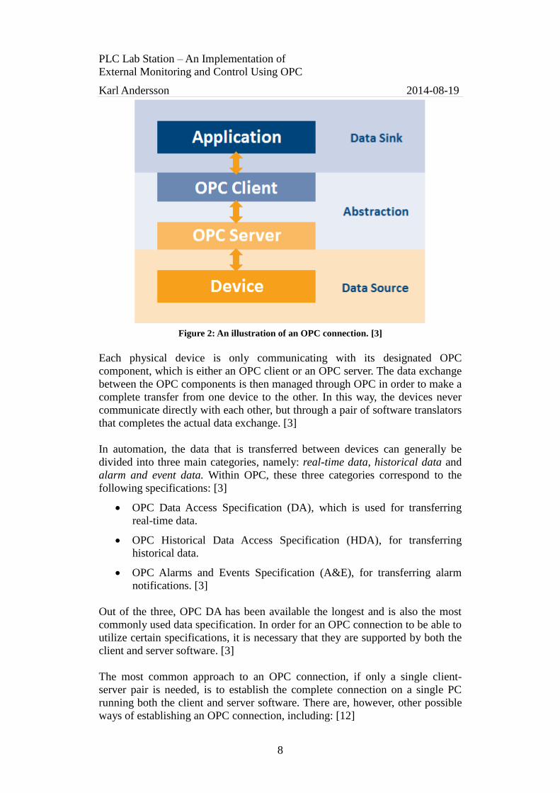
This level of abstraction is implemented using a client-server approach, which
is based on two OPC components; the OPC client and the OPC server. Figure 2
illustrates how the OPC client and server allows the data sink and data source to
communicate without having to be directly compatible with each other. The
OPC client and server acts as translators between each device’s original
communication interface and the OPC standard. [3]
PLC Lab Station – An Implementation of
External Monitoring and Control Using OPC
Karl Andersson 2014-08-19
8
Figure 2: An illustration of an OPC connection. [3]
Each physical device is only communicating with its designated OPC
component, which is either an OPC client or an OPC server. The data exchange
between the OPC components is then managed through OPC in order to make a
complete transfer from one device to the other. In this way, the devices never
communicate directly with each other, but through a pair of software translators
that completes the actual data exchange. [3]
In automation, the data that is transferred between devices can generally be
divided into three main categories, namely: real-time data, historical data and
alarm and event data. Within OPC, these three categories correspond to the
following specifications: [3]
OPC Data Access Specification (DA), which is used for transferring
real-time data.
OPC Historical Data Access Specification (HDA), for transferring
historical data.
OPC Alarms and Events Specification (A&E), for transferring alarm
notifications. [3]
Out of the three, OPC DA has been available the longest and is also the most
commonly used data specification. In order for an OPC connection to be able to
utilize certain specifications, it is necessary that they are supported by both the
client and server software. [3]
The most common approach to an OPC connection, if only a single client-
server pair is needed, is to establish the complete connection on a single PC
running both the client and server software. There are, however, other possible
ways of establishing an OPC connection, including: [12]

PLC Lab Station – An Implementation of
External Monitoring and Control Using OPC
Karl Andersson 2014-08-19
9
Connection between an OPC client and several different OPC servers.
Connection between an OPC client and an OPC server on different PCs
in a network.
Connection directly between OPC servers that should share data. [12]
2.4 PROFIBUS
Process Field Bus, or PROFIBUS, is a networking standard that is commonly
used for data communication within control systems worldwide. It is based on
traditional master-slave communication. The master devices are referred to as
active stations, and they control the use of the bus and can transfer data
whenever they are in access of the bus. The slave devices are called passive
stations and are only allowed to transmit data if a master has requested it, but
can always receive data that is being sent to them. [13]
The PROFIBUS standard supports up to 127 nodes on the same network and
data can be transmitted at speeds between 9.6 kbps and 12 Mbps, depending on
the transmission distance. Three different versions of the standard are available,
namely: [13]
PROFIBUS Distributed Peripheral (DP), which uses master-slave
communication and allows several masters and slaves on the same
network. A slave can only be assigned to one master at a time. This
means that a slave can only receive data from its assigned master, while
masters are still able to request data from all slaves on the network. [13]
PROFIBUS Fieldbus Message Specification (FMS), which provides the
possibility of master-master communication. If needed, all devices on
the network can be configured as masters. [13]
PROFIBUS Process Automation (PA), which is essentially the same as
DP, with the exception that the allowed voltage and current levels are
restricted to meet certain safety requirements. [13]
2.5 Industrial Ethernet
Today, Ethernet is used in virtually all office networks to interconnect PCs,
servers, printers and other devices, as well as to allow access to the Internet and
other networks. Due to the general recognition of Ethernet, it has also become
accepted as a means of connecting devices and systems in the industry, which
has formed the Industrial Ethernet standard. [9]
PLC Lab Station – An Implementation of
External Monitoring and Control Using OPC
Karl Andersson 2014-08-19
10
Despite the fact that Industrial Ethernet is based upon the regular Ethernet
standard, there are some differences in how the two are implemented. The
major difference lies in the hardware, since an Industrial Ethernet network has
to withstand the harsh environments that can be found in many industrial plants
and factories. Another difference is the use of the network protocols of the two
standards. Ethernet is commonly used to access external devices and
information is often sent via the Internet, whereas Industrial Ethernet
communication is often local, with data exchange being performed between
devices on the same network. [9]
With Industrial Ethernet, data transfer is generally carried out at speeds between
10 Mbps and 100 Mbps, utilizing full duplex. The equipment is specified to
operate using 24 V DC and often has redundant power supplies for increased
durability. The use of Ethernet in both office and industrial environments can
reduce the overall networking costs, since the need for other types of
specialized equipment for implementing and maintaining separate networks can
be reduced. [9]
2.6 Automotive industry processes
Modern day automotive manufacturing relies on the very same principle that
was once introduced by Henry Ford, namely the moving assembly line. The
manufacturing process is divided into several stations, each at which specific
tasks are performed. [14] The typical modern manufacturing chain is divided
into five stages, which include metal pressing, body assembly, paint, powertrain
manufacturing and final assembly [15].
Today, the largest difference compared to the conventional moving assembly
line is that the manufacturing processes are almost completely automated [16].
The different stages are connected using automated conveyor systems that
transport the assembled parts between stations [17] and factory workers are
replaced by robots that perform the repetitive tasks at each stage [16].
Smaller automotive manufacturers benefit from using flexible assembly lines,
where several different car models can be assembled using the same equipment.
This requires some form of recognition system that can distinguish the different
models and parts, in order for the system to function correctly. [18]

PLC Lab Station – An Implementation of
External Monitoring and Control Using OPC
Karl Andersson 2014-08-19
11
3 Methodology This chapter presents the methodology used during the course of the project.
Section 3.1 describes the literary study, section 3.2 provides information about
the solution methods and section 3.3 presents the evaluation methods used for
the final design.
3.1 Literary study
The initial phase of the project required a general understanding of all the
included elements. In order to achieve this, a literary study was performed, with
the goal of obtaining enough information in order to simplify the subsequent
steps towards the project completion. The outcome of this literary study has
been summarized and is presented in chapter 2.
The literary study was carried out using a number of references, both web-
based and in the form of books. These references were then reviewed and
summarized in order to provide information essential to this project. To avoid
unreliable facts and possible product placement, care was taken when reviewing
the sources, making sure that only relevant and trustworthy information should
be presented in this report.
3.2 Solutions
The requirements presented in section 1.2 specify that the lab station should
contain general functionality of some common industrial processes and also be
able to simulate the processes researched in the other two theses [7] [8],
mentioned in section 1.6. The lab station should also include active means of
communication and external monitoring and control possibilities. This means
that the lab setup should be made quite versatile and be able to perform a
variety of different tasks.
The component selection was carried out with respect to the given budget, the
requirements from ÅF Consult, as well as the research regarding the automotive
industry processes, presented in section 2.6.
The implementation and construction of the lab station was carried out by the
following general steps:
Design of the lab station.
Construction of the lab station.
Creation of a test program.
Implementation of external monitoring and control using OPC.
PLC Lab Station – An Implementation of
External Monitoring and Control Using OPC
Karl Andersson 2014-08-19
12
3.3 Evaluation
During the course of the design and implementation of the lab station, manual
testing of each individual component and solution was performed in order to
ensure that a satisfactory result should be achieved. The test program created
during the solution implementation was also used in order to evaluate the
overall functionality of the lab station.
The questions formulated in section 1.4 were used as the basis of the analysis
and evaluation of the finished solutions. An evaluation of the overall
possibilities of the lab station was considered as a part of the formulation of the
lab tasks.

PLC Lab Station – An Implementation of
External Monitoring and Control Using OPC
Karl Andersson 2014-08-19
13
4 Design This chapter contains descriptions of the design and implementation of the
provided solutions. Section 4.1 describes the design of the lab station, section
4.2 contains information about the control implementation with the PLCs,
section 4.3 describes the PLC test program and section 4.4 presents the solution
for the external monitoring and control using OPC.
4.1 Lab station
The complete lab setup has been designed according to the initial requirements.
These requirements include the 6 500 SEK budget and the fact that the station
should be able to simulate some common industrial processes. The overall
structure of the finished lab station can be divided into two major parts, namely
the conveyor belt and the robotic arm. Figure 3 shows an overview of the lab
station where the conveyor belt and the robotic arm are labeled. The PLC
systems are described in section 4.2. Subsections 4.1.1 to 4.1.3 contain
information about the conveyor belt, the robotic arm and some additional
equipment respectively.
Figure 3: An overview of the lab station.
4.1.1 Conveyor belt
The first major section of the lab setup is the conveyor belt, which is designed
to be able to store, transport, differentiate and sort small cubes of various

PLC Lab Station – An Implementation of
External Monitoring and Control Using OPC
Karl Andersson 2014-08-19
14
materials. Apart from the physical conveyor belt itself, this section integrates a
storage unit and two unloading zones. Figure 4 shows the conveyor belt
assembly with some important parts labeled.
Figure 4: The conveyor belt with its parts labeled.
The design of the conveyor belt is very simple and consists of two plastic
pulleys and three thin belts. These pulleys were printed in plastic using a 3D-
printer and are designed to fit the dimensions of the belts. The pulleys were
designed using SolidWorks 3D CAD, and the finished design can be seen in
Appendix A. One of the pulleys is driven by a DC motor which is connected to
a pulse width modulation module [19] for speed control, and the other pulley is
mounted using ball bearings. The assembly is also equipped with a photo diode
that can be used to monitor the speed of the conveyor belt, with the help of four
thin arms mounted on the motor shaft.
The storage unit is designed to hold a number of cubes that should be used
during the various tasks that can be performed at the lab station. In order to be
able to push a cube from the storage unit onto the conveyor belt, a revolving
arm, driven by a 6 V DC motor, is fitted to the side of the unit. Along with this
pusher arm, a photo diode is mounted. This photo diode allows for the
possibility to verify when the arm has completed a revolution, i.e. pushed a
cube out. The cubes that are pushed out of the storage unit slides down a ramp
onto the conveyor belt.
The conveyor belt is equipped with two sensors that are used to differentiate
between cubes of different materials. The setup includes an inductive sensor
[20] and a photoelectric sensor [21], which makes it possible to differentiate
metallic materials from non-metallic. In the current setup, the inductive sensor
is integrated in the ramp from the storage unit and the optical sensor is placed
directly after this ramp, at the start of the conveyor belt. The setup, however,
allows for relocation of the sensors and addition of further sensors for a simple
reconfiguration and an extended functionality.

PLC Lab Station – An Implementation of
External Monitoring and Control Using OPC
Karl Andersson 2014-08-19
15
The unloading zones consist of two sloped ramps positioned perpendicular to
the movement of the conveyor belt. In order to be able to move cubes from the
conveyor belt onto the ramps, two hinged walls are fitted. These walls are
controlled using two solenoid actuators and are used to redirect the passing
cubes from the conveyor belt onto the ramps when desired. Each of the two
ramps has an integrated limit switch that triggers every time a cube passes,
making it possible to monitor when cubes are present at the unloading stations.
On the far end of the conveyor belt, an additional limit switch is mounted. This
switch is intended to serve as an emergency switch and can be used to set a
warning or immediately stop the conveyor belt if triggered.
4.1.2 Robotic arm
The second major part of the lab station is the robotic arm, which is designed as
a pick-and-place device that should be used to move the cubes between
different positions on the lab station. The robotic arm is based on a kit [22] that
has been modified with a number of sensors, in order to make automated
control possible.
Since the kit with the robotic arm was actually intended to be controlled using
switches on a control box, it initially had no means of reading its current state.
In order to be able to implement automatic control, it therefore had to be
modified with a number of sensors that could provide monitoring possibilities.
In order to perform a certain task, it is necessary to know where the robotic arm
is situated, and how each axis should be moved in order to reach the desired
position.
The arm consists of an adjustable grip, three foldable joints and a revolving
base, which are controlled by five individual 3 V DC motors. Figure 5 shows
the different parts of the robotic arm kit.
Figure 5: The robotic arm kit with its parts labeled. [23]
PLC Lab Station – An Implementation of
External Monitoring and Control Using OPC
Karl Andersson 2014-08-19
16
In order to monitor the state of the adjustable grip, it is fitted with a resistive
pressure sensor [24]. By using this pressure sensor it is possible to read out
whether the grip is holding an object or not. If the material of the object is
known, hence the weight of the object is known, the pressure of the claw could
be adjusted accordingly.
The top and middle foldable joints are monitored using resistive flex sensors
[25] and are designed to be operated in a range from fully extended to an angle
of approximately 90 degrees. The two flex sensors are stationary mounted on
one end of the joint and slides freely in a slot on the other end, in order to not
get stretched or deformed during operation. The bottom joint of the arm uses
two limit switches and is only designed to be operated in two positions; one
vertical and one nearly horizontal.
The revolving base is equipped with an inductive sensor [20], which is used to
sense three different metal plates placed along the edge of the base, which
correspond to preset angles for the rotation of the arm. The rotation of the arm
has a total range of 180 degrees. In order to prevent it from rotating too far, the
base is equipped with a limit switch. This limit switch is also intended to be
used as a reference point when the arm is positioned during startup.
The robotic arm is mounted on a carriage that can be moved along the lab
station by means of a chain that is driven by a 6 V DC motor. This solution
makes it possible to cover a larger area of the lab station than would be possible
if the arm had been stationary. The placement of the carriage is monitored using
an ultrasonic range sensor [26], which measures the distance to the edge of the
carriage. There are also limit switches placed at the end positions, as well as a
photo diode placed in the middle of the range, which can be used as
complements to the range sensor.
The total of six DC motors that control the movement of the robotic arm are
controlled using two relays each, in order to allow for operation in both
directions. The relays are controlled using 24 V DC and supplies the motors
with 3 and 6 V DC respectively. Figure 6 shows the schematic of the control
circuitry for the motors.

PLC Lab Station – An Implementation of
External Monitoring and Control Using OPC
Karl Andersson 2014-08-19
17
Figure 6: Electrical schematic of the DC motor control circuitry.
4.1.3 Additional sensors
In addition to the conveyor belt and the robotic arm, the lab station is also
equipped with three additional sensors that can be used to perform different
measurements. These additional sensors are integrated into the lab station in
order to realize the simulation of the industrial processes that are examined in
the other two theses [7] [8]. When working with the lab station, these sensors
can either be used independently, as part of simpler tasks, or integrated into the
complete lab setup, as they are accessible using the robotic arm.
The additional sensors include: a vertically mounted range sensor, intended to
be used for height measurements of the cubes; a temperature sensor that can be
used to measure a temperature deviation if some of the cubes are heated or
cooled; a load cell that is used to weigh the cubes, which makes it possible to
further differentiate cubes of the same material after the initial sorting on the
conveyor belt.
The range sensor and the temperature sensor are integrated into the same unit,
where a cube or some other object can be placed on a metal surface in order for
both measurements to be performed. The range sensor is mounted with the
metal surface as a reference from which the height of the object can be
measured and the temperature sensor is fixated directly underneath the metal
surface. The load cell is placed next to the storage unit. It is equipped with a
metal plate on which an object can be placed in order to measure its weight.
These sensors and their respective functionality are described more in detail in
the other two theses [7] [8], where they are used as part of the simulation of
industrial processes.
4.2 PLC setup
The hardware used to control the process flow of the lab station consists of two
Siemens SIMATIC S7 PLC systems from the 300 [5] and 400 [6] series

PLC Lab Station – An Implementation of
External Monitoring and Control Using OPC
Karl Andersson 2014-08-19
18
respectively. The two PLC systems are connected via PROFIBUS to be able to
communicate directly with each other and exchange data. The configuration
was performed using Siemens SIMATIC STEP 7. Subsections 4.2.1 to 4.2.3
cover the configurations of the two PLC systems and the communication setup
respectively.
4.2.1 Siemens S7-400
The S7-400 system consists of: a CPU with a PPROFIBUS DP connection; a
power supply; a communications module with an Ethernet connection; a digital
output module with 32 outputs. The complete hardware configuration of the
system can be seen in Figure 7.
Figure 7: Hardware configuration for the S7-400.
The S7-400 system has two main assignments in the finished PLC setup, which
are to control the movement of the robotic arm and manage the data that is
being exchanged between the involved nodes in the network. The digital
outputs on the S7-400 system are used to control the six DC motors in the
robotic arm. As mentioned in subsection 4.1.2, each motor of the robotic arm is
designed to run in both directions, hence controlled using two relays each. This
means that 12 of the 32 available outputs are used to control the relays that
operate the motors. The electrical schematics of the digital output module in the
S7-400 system is provided in Appendix B.
Since the S7-400 system does not have any input modules, it communicates
with the S7-300 system using the PROFIBUS DP network in order to retrieve
the necessary data. The communications module in the S7-400 system is used to

PLC Lab Station – An Implementation of
External Monitoring and Control Using OPC
Karl Andersson 2014-08-19
19
connect the PLC to Ethernet, allowing for communication with the OPC server
on the PC, described in subsection 4.4.1.
4.2.2 Siemens S7-300
The S7-300 system includes: a CPU with a PROFIBUS DP connection; a power
supply; a digital input module with 16 inputs; a digital output module with eight
outputs; an analog input module with eight 12-bit inputs; an analog output
module with four 12-bit outputs. Figure 8 shows the complete hardware
configuration, with the exception of the power supply.
Figure 8: Hardware configuration for the S7-300.
The S7-300 system reads the input signals from all of the sensors on the lab
station, both analog and digital. It also controls the three actuators on the
conveyor belt along with the pulse width modulation module that controls the
conveyor belt motor. The electrical schematics of the S7-300 input and output
modules are included in appendices. Appendix C shows the digital input
module, Appendix D shows the digital output module, Appendix E shows the
analog input module and Appendix F shows the analog output module.
Since the S7-300 system has the most input and output modules, this is where
the majority of the test program is executed. The information that is needed
elsewhere in the system is sent to the S7-400 using the PROFIBUS DP
network. The data used by the OPC server is then accessed through the S7-400.
4.2.3 Communication setup
The PLC systems are interconnected into a PROFIBUS DP network to allow for
means of data exchange between the two. The communication setup also
PLC Lab Station – An Implementation of
External Monitoring and Control Using OPC
Karl Andersson 2014-08-19
20
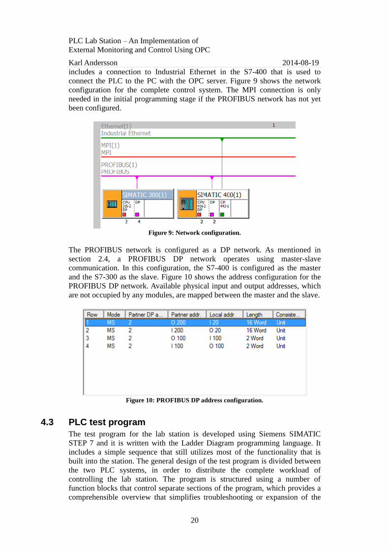
includes a connection to Industrial Ethernet in the S7-400 that is used to
connect the PLC to the PC with the OPC server. Figure 9 shows the network
configuration for the complete control system. The MPI connection is only
needed in the initial programming stage if the PROFIBUS network has not yet
been configured.
Figure 9: Network configuration.
The PROFIBUS network is configured as a DP network. As mentioned in
section 2.4, a PROFIBUS DP network operates using master-slave
communication. In this configuration, the S7-400 is configured as the master
and the S7-300 as the slave. Figure 10 shows the address configuration for the
PROFIBUS DP network. Available physical input and output addresses, which
are not occupied by any modules, are mapped between the master and the slave.
Figure 10: PROFIBUS DP address configuration.
4.3 PLC test program
The test program for the lab station is developed using Siemens SIMATIC
STEP 7 and it is written with the Ladder Diagram programming language. It
includes a simple sequence that still utilizes most of the functionality that is
built into the station. The general design of the test program is divided between
the two PLC systems, in order to distribute the complete workload of
controlling the lab station. The program is structured using a number of
function blocks that control separate sections of the program, which provides a
comprehensible overview that simplifies troubleshooting or expansion of the

PLC Lab Station – An Implementation of
External Monitoring and Control Using OPC
Karl Andersson 2014-08-19
21
program. An organization block is used in each PLC system to interconnect the
individual function blocks and call them when they should be executed in
accordance with the program flow.
The initial phase of the test program executes a startup sequence that moves the
robotic arm to a suitable position before the rest of the program is started. This
is done to prevent any damage to the lab station that might occur if the arm has
been stopped in an inconvenient position as a result of a loss of power or a
system failure. At the end of the startup sequence a memory bit is set high, in
order to show that the startup has completed. This memory bit is then used to
initialize the subsequent sections of the test program.
The movement of the robotic arm is controlled using the values from the
included sensors. The top and middle foldable joints, as well as the adjustable
grip and the horizontal positioning of the carriage, are all monitored using
analog sensors and are controlled using compare blocks. These blocks compare
the input values from the sensors to predefined set points that correspond to
specific positions. The outputs of the compare blocks operate the corresponding
physical outputs of the PLCs. Figure 11 shows an example of a compare block
that is used to operate the top foldable joint by monitoring the flex sensor and
comparing its value to a fixed set point.
Figure 11: An example of a compare block.
The positioning of the bottom joint and the revolving base of the robotic arm
are monitored using digital sensors and are controlled accordingly, where the
movement is restricted to a number of fixed positions. The conveyor belt speed
is controlled by a memory word that is set to an appropriate value, and the
sensors on the conveyor belt assembly are all digital, hence either active or not
in the program.
The next section of the test program pushes a cube from the storage onto the
conveyor belt and starts the belt itself. The sensors on the conveyor belt
assembly are used to differentiate the material of the cube, which is then sorted
by being pushed down the corresponding unloading zone. This step then
triggers the robotic arm, which moves to pick up the cube and place it back into
the storage.
PLC Lab Station – An Implementation of
External Monitoring and Control Using OPC
Karl Andersson 2014-08-19
22
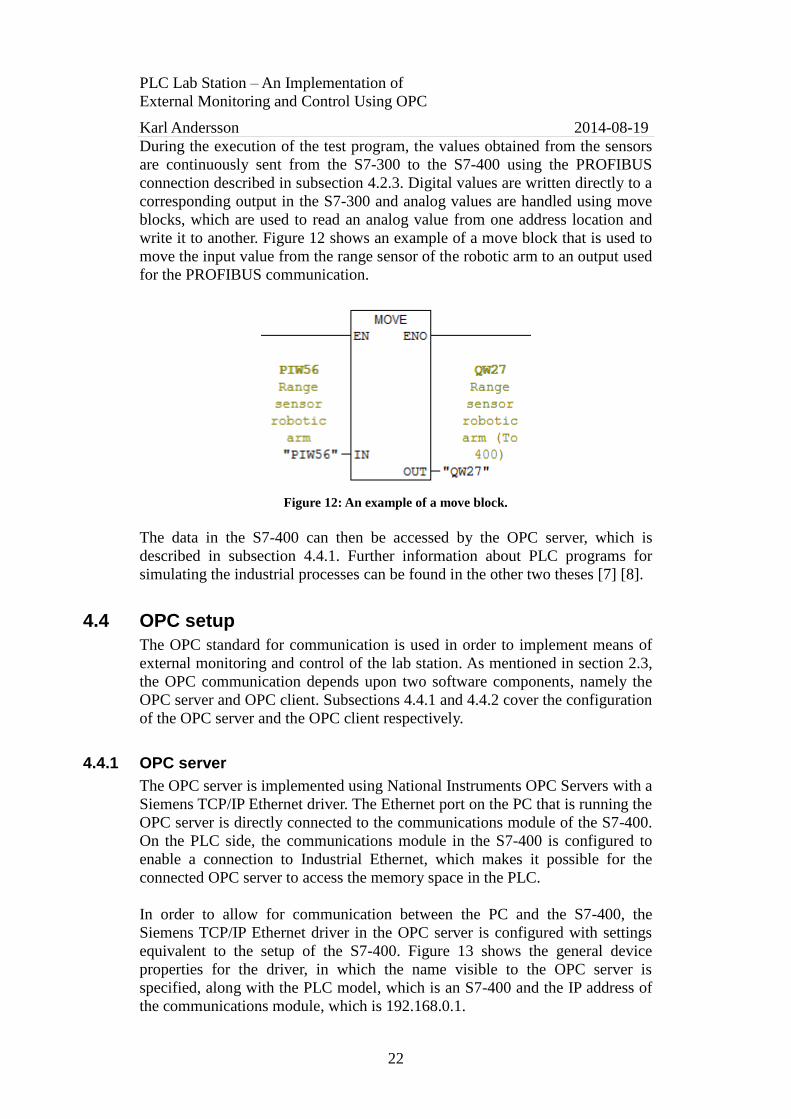
During the execution of the test program, the values obtained from the sensors
are continuously sent from the S7-300 to the S7-400 using the PROFIBUS
connection described in subsection 4.2.3. Digital values are written directly to a
corresponding output in the S7-300 and analog values are handled using move
blocks, which are used to read an analog value from one address location and
write it to another. Figure 12 shows an example of a move block that is used to
move the input value from the range sensor of the robotic arm to an output used
for the PROFIBUS communication.
Figure 12: An example of a move block.
The data in the S7-400 can then be accessed by the OPC server, which is
described in subsection 4.4.1. Further information about PLC programs for
simulating the industrial processes can be found in the other two theses [7] [8].
4.4 OPC setup
The OPC standard for communication is used in order to implement means of
external monitoring and control of the lab station. As mentioned in section 2.3,
the OPC communication depends upon two software components, namely the
OPC server and OPC client. Subsections 4.4.1 and 4.4.2 cover the configuration
of the OPC server and the OPC client respectively.
4.4.1 OPC server
The OPC server is implemented using National Instruments OPC Servers with a
Siemens TCP/IP Ethernet driver. The Ethernet port on the PC that is running the
OPC server is directly connected to the communications module of the S7-400.
On the PLC side, the communications module in the S7-400 is configured to
enable a connection to Industrial Ethernet, which makes it possible for the
connected OPC server to access the memory space in the PLC.
In order to allow for communication between the PC and the S7-400, the
Siemens TCP/IP Ethernet driver in the OPC server is configured with settings
equivalent to the setup of the S7-400. Figure 13 shows the general device
properties for the driver, in which the name visible to the OPC server is
specified, along with the PLC model, which is an S7-400 and the IP address of
the communications module, which is 192.168.0.1.

PLC Lab Station – An Implementation of
External Monitoring and Control Using OPC
Karl Andersson 2014-08-19
23
Figure 13: Driver device properties.
Figure 14 shows the communication parameters for the TCP/IP Ethernet driver.
These are configured in order to address the communication between the PC
and the CPU in the S7-400 system, which is located in slot 3 in its rack. The
driver is also setup to use big endian, which is the default byte order used in the
S7-400, showed in Figure 15. This ensures for consistent data management
between the PC and the S7-400.
Figure 14: Driver communication parameters.
Figure 15: Driver byte order.
Figure 16 shows an example of the configurable properties for the OPC tags.
Each tag is provided with a short name, along with the address location that it
should be linked to in the PLC and also a description that is used to clarify the
purpose of the tag. The data type is specified according to the memory type of
each individual tag. Tags that are used for control purposes are configured to
allow both read and write operations, while tags dedicated strictly for
monitoring are restricted as read only in order to prevent any conflicts and
possible errors. Finally, the refresh rate of the tag is specified.

PLC Lab Station – An Implementation of
External Monitoring and Control Using OPC
Karl Andersson 2014-08-19
24
Figure 16: OPC server tag properties.
The OPC server contains tags that are linked to relevant address locations used
in the test program, which consist of both memory locations and physical
outputs of the S7-400 system. Figure 17 shows an overview of the OPC server
where a selection of the included tags is visible.
Figure 17: OPC server overview.
4.4.2 OPC client
The OPC client is implemented using National Instruments LabVIEW, to which
the OPC server described in subsection 4.4.1 is connected. A graphical user
interface created using the LabVIEW environment provides means of external
monitoring and control of the lab station. This user interface provides real-time
access to all of the variables that are being monitored and controlled.
PLC Lab Station – An Implementation of
External Monitoring and Control Using OPC
Karl Andersson 2014-08-19
25
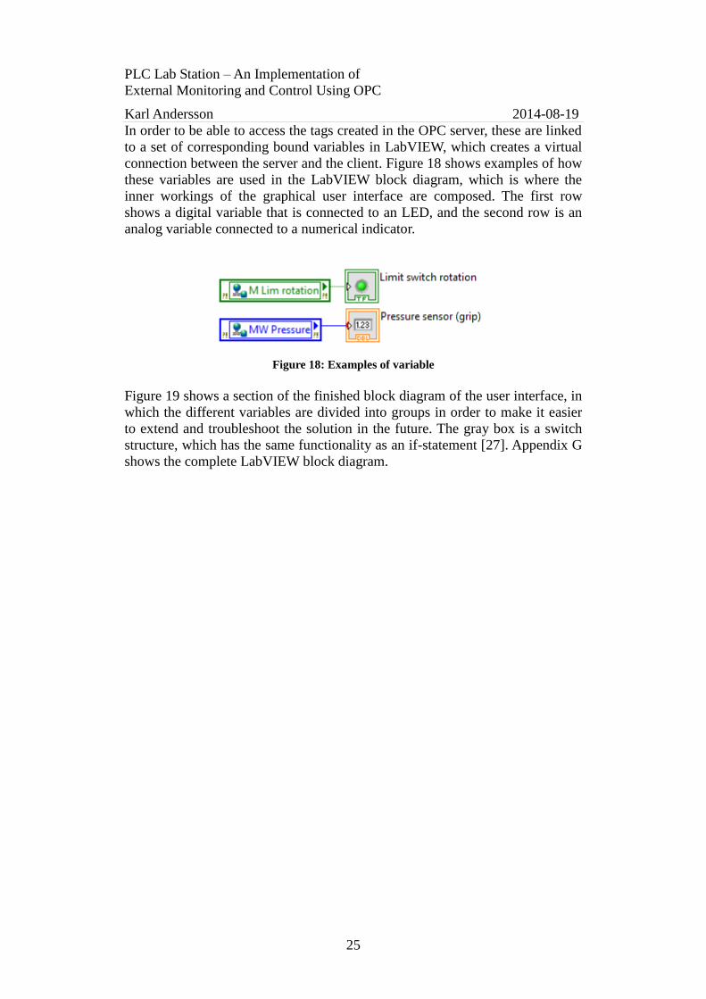
In order to be able to access the tags created in the OPC server, these are linked
to a set of corresponding bound variables in LabVIEW, which creates a virtual
connection between the server and the client. Figure 18 shows examples of how
these variables are used in the LabVIEW block diagram, which is where the
inner workings of the graphical user interface are composed. The first row
shows a digital variable that is connected to an LED, and the second row is an
analog variable connected to a numerical indicator.
Figure 18: Examples of variable
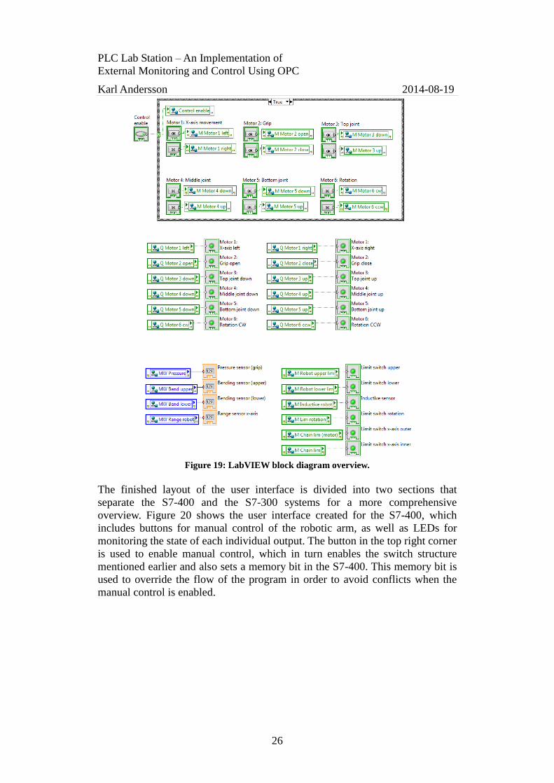
Figure 19 shows a section of the finished block diagram of the user interface, in
which the different variables are divided into groups in order to make it easier
to extend and troubleshoot the solution in the future. The gray box is a switch
structure, which has the same functionality as an if-statement [27]. Appendix G
shows the complete LabVIEW block diagram.
PLC Lab Station – An Implementation of
External Monitoring and Control Using OPC
Karl Andersson 2014-08-19
26
Figure 19: LabVIEW block diagram overview.
The finished layout of the user interface is divided into two sections that
separate the S7-400 and the S7-300 systems for a more comprehensive
overview. Figure 20 shows the user interface created for the S7-400, which
includes buttons for manual control of the robotic arm, as well as LEDs for
monitoring the state of each individual output. The button in the top right corner
is used to enable manual control, which in turn enables the switch structure
mentioned earlier and also sets a memory bit in the S7-400. This memory bit is
used to override the flow of the program in order to avoid conflicts when the
manual control is enabled.

PLC Lab Station – An Implementation of
External Monitoring and Control Using OPC
Karl Andersson 2014-08-19
27
Figure 20: Graphical user interface for monitoring and control of the S7-400.
Figure 21 shows the user interface for monitoring and control of the S7-300.
The left part is used to monitor the values of the sensors on the robotic arm,
which are both analog and digital sensors. The right part can be used to monitor
and control the conveyor belt. Here, a value for the speed of the conveyor belt
can be entered, and all of the sensors and actuators on the conveyor belt
assembly can be monitored. Analog values are monitored numerically and
digital values are monitored using LEDs.
Figure 21: Graphical user interface for monitoring and control of the S7-300.

PLC Lab Station – An Implementation of
External Monitoring and Control Using OPC
Karl Andersson 2014-08-19
28
5 Results This chapter presents the results of the evaluation of the implemented design
and the completed solutions, as well as suggestions for lab tasks that can be
performed using the finished lab station and some comparable solutions that are
already present. Section 5.1 includes the evaluation of the lab station and
section 5.2 presents the evaluation of the external monitoring and control
solution. The formulated suggestions of lab tasks are presented in section 5.3.
Similar solutions are described in section 5.4.
5.1 Evaluation of the lab station
This section contains the evaluation of the lab station, mainly with respect to its
functionality and reliability. The evaluation results for the conveyor belt and the
robotic arm are presented in subsection 5.1.1 and 5.1.2 respectively. In order to
completely understand the explanations presented here, it is important to have
read subsections 4.1.1 and 4.1.2 in advance, which describe the design of the
conveyor belt and the robotic arm respectively.
5.1.1 Conveyor belt
The conveyor belt has a good level of functionality, which relates to the
research about the automotive industry processes presented in section 2.6. This
research showed that conveyor systems and some form of recognition systems
are commonly used in the automotive industry. The actual implementation of a
simulation of an industrial processes was not included in this project, but was,
however, part of the other two theses [7] [8].
The overall reliability of the conveyor belt assembly is good, with all the
sensors, limit switches and actuators working as expected with a consistent
behavior. There are, however, some issues present in the design, with the largest
one being the unloading stations, which have proven to have an inconsistent
behavior. The problem is that the cubes do not always stop in the same positions
when sliding down the ramps. This in turn affects the operation of the robotic
arm, as sometimes it can miss cubes. In order to prevent any mechanical
damage to the equipment, it has sometimes proven necessary to reposition the
cubes after they have been sorted.
Another issue that has been found is that the storage unit can get obstructed if
the cubes are poorly placed, resulting in the pusher arm not being able to move
a cube from the storage onto the conveyor belt. This can, however, be avoided
by not placing more than one cube at a time in the storage unit.
PLC Lab Station – An Implementation of
External Monitoring and Control Using OPC
Karl Andersson 2014-08-19
29
5.1.2 Robotic arm
The robotic arm has a good level of functionality that can also be associated
with the initial research of the automotive industry processes presented in
section 2.6. As the research states, the automotive industry is highly dependent
on the use of robotic arms that perform repetitive tasks. The design and
placement of the sensors on the robotic arm results in a limited movement
compared to the original kit. However, the implementation of the arm at the lab
station still makes it possible to reach all of the required positions, which means
that the design does not actually limit the functionality of the arm.
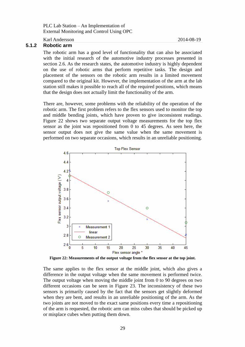
There are, however, some problems with the reliability of the operation of the
robotic arm. The first problem refers to the flex sensors used to monitor the top
and middle bending joints, which have proven to give inconsistent readings.
Figure 22 shows two separate output voltage measurements for the top flex
sensor as the joint was repositioned from 0 to 45 degrees. As seen here, the
sensor output does not give the same value when the same movement is
performed on two separate occasions, which results in an unreliable positioning.
Figure 22: Measurements of the output voltage from the flex sensor at the top joint.
The same applies to the flex sensor at the middle joint, which also gives a
difference in the output voltage when the same movement is performed twice.
The output voltage when moving the middle joint from 0 to 90 degrees on two
different occasions can be seen in Figure 23. The inconsistency of these two
sensors is primarily caused by the fact that the sensors get slightly deformed
when they are bent, and results in an unreliable positioning of the arm. As the
two joints are not moved to the exact same positions every time a repositioning
of the arm is requested, the robotic arm can miss cubes that should be picked up
or misplace cubes when putting them down.

PLC Lab Station – An Implementation of
External Monitoring and Control Using OPC
Karl Andersson 2014-08-19
30
Figure 23: Measurements of the output from the flex sensor at the middle joint.
Another issue is that the ultrasonic range sensor, which was originally intended
to be used as part of the placement of the carriage for the robotic arm, tends to
lose focus of the carriage as it moves further away from the sensor. The main
reason for this is that the spread of the area that the sensor monitors is interfered
by other objects on the lab station. However, the positioning of the carriage can
still be performed using the limit switches and the photo diode that is placed
along the path of the carriage.
The resistive pressure sensor that is mounted in the adjustable grip has also
proven to not work entirely as intended. The functionality of this sensor still
makes it possible to read out whether the grip is holding an object or not, but it
cannot be used to monitor the pressure applied to the object. This is due to the
fact that the mounting inside the grip makes the pressure distribute unevenly
across the sensor. This gives a very abrupt change in resistance which results in
an output voltage that increases from its minimum value to nearly its maximum
as soon as an object is gripped.
5.2 Evaluation of the monitoring and control solution
The external monitoring and control implementation is working at a satisfactory
level. The time frame of the project did not allow for much effort to be put into
this area, which in turn has resulted in a less extensive solution than at first
intended. The current setup only utilizes the OPC DA specification, using real-
time data, but future expansion of the solution could include the usage of other
specifications as well. However, the included functionality and the OPC
communication between the PC and the S7-400 are working as expected.

PLC Lab Station – An Implementation of
External Monitoring and Control Using OPC
Karl Andersson 2014-08-19
31
The solution with the PC based graphical user interface provides an extended
functionality as the complete lab station can be monitored and controlled
externally if needed. If there are several simultaneous users of the lab station,
each user can have an individual solution that is designed for the respective
application.
In this current OPC setup, both the server and the client reside on the same PC,
but there is also a possibility to distribute these components if needed. By using
a separate PC to run the OPC server software, it would be possible to allow for
employees to run separate OPC clients on their own PCs and accessing the
server using the office network. In this way, each employee can get the chance
to design an individual graphical user interface to use with the lab station.
5.3 Lab tasks
The main objective of this lab assignment is to design a graphical user interface
that can be used to monitor and control the lab station remotely. The following
tasks are intended to be performed after the tasks formulated in the other two
theses [7] [8] have been completed, including the hardware configuration and
control implementation of the conveyor belt, as well as the control
implementation of the robotic arm. Therefore, this lab task requires the use of
the ready-configured PLC setup, consisting of the S7-300 and S7-400 systems
that have been interconnected using a PROFIBUS DP network. Below are six
tasks that are intended as an introduction to OPC and some of its possibilities:
1) Establish an Ethernet connection between the S7-400 system and the PC.
a) Make sure that the Industrial Ethernet communication for the S7-400
communications module is enabled. This is done in the hardware
configuration of the S7-400.
b) Connect the S7-400 communications module to the PC.
c) Configure the OPC server software with the S7-400 communications
driver. In the following tasks, each address location in the PLC that
should be accessed externally has to be mapped to a corresponding tag
in the OPC server.
2) Design and implement a monitoring stage that can be used to read the state
of the required inputs, outputs and memories that have been used in the
previous stages to implement control of the conveyor belt and the robotic
arm.
a) Map all of the needed address locations to corresponding OPC tags.
b) Include the tags to be used in LabVIEW by linking them to bound
variables.
c) Create a graphical user interface for the monitoring stage which is easy
to understand. Digital values can be monitored using LEDs and analog
values can be monitored either numerically or graphically, depending on
the application.

PLC Lab Station – An Implementation of
External Monitoring and Control Using OPC
Karl Andersson 2014-08-19
32
3) Design and implement some means of manual control for the lab station.
This could be done for either the conveyor belt or the robotic arm, or both if
sufficient time is given. (Tip: Extend the PLC program to use a number of
memories that in turn control the outputs, rather than operating the outputs
directly. This makes it possible to intercept the manual control stage if an
emergency stop is activated or if it for any other reason should not be
allowed by the program.)
a) In the same way as in the previous task, map all required address
locations into OPC tags and then include them in LabVIEW. Make sure
to change the configuration of the concerned tags in the server to allow
for both read and write operations.
b) Implement means of enabling the manual control so that this feature is
only turned on when being used.
c) Extend the graphical user interface to accommodate the control stage as
well, which could be operated using switches or buttons.
4) Provide the graphical user interface with a software controlled emergency
stop that works in unity with the physical emergency stop at the lab station.
5) Implement some means of reading out the speed of the conveyor belt in the
graphical user interface. This can be performed using the photo diode that is
placed on the motor axis of the conveyor belt. A suggestion is to display the
measured speed in revolutions per minute or meters per second.
6) Provide means of integrating the readouts from the additional sensors with
the PLC program. A possible implementation could be to compare the
values from the load cell with a reference value, which could then be used
to set a memory bit if the weight of a cube is too high or low. This could be
used to sort out cubes that do not match the reference value.
5.4 Similar solutions
Two similar solutions to the designed and implemented lab station have been
found, and are briefly described below for comparative purposes:
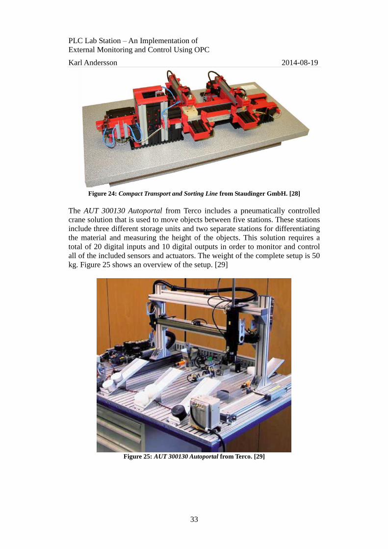
The Compact Transport and Sorting Line from Staudinger GmbH includes a
conveyor belt with a storage unit and two unloading stations. It provides the
possibility to store and transport objects, and also to differentiate and sort the
objects as they are transported along the conveyor belt. It requires a total of 13
digital inputs and eight digital outputs to monitor and control the complete
setup, hence only relies on digital data. The setup has a total weight of 4.7 kg
and it is shown in Figure 24. [28]
PLC Lab Station – An Implementation of
External Monitoring and Control Using OPC
Karl Andersson 2014-08-19
33
Figure 24: Compact Transport and Sorting Line from Staudinger GmbH. [28]
The AUT 300130 Autoportal from Terco includes a pneumatically controlled
crane solution that is used to move objects between five stations. These stations
include three different storage units and two separate stations for differentiating
the material and measuring the height of the objects. This solution requires a
total of 20 digital inputs and 10 digital outputs in order to monitor and control
all of the included sensors and actuators. The weight of the complete setup is 50
kg. Figure 25 shows an overview of the setup. [29]
Figure 25: AUT 300130 Autoportal from Terco. [29]

PLC Lab Station – An Implementation of
External Monitoring and Control Using OPC
Karl Andersson 2014-08-19
34
6 Discussion This chapter contains the final discussion and comments regarding the solutions
and the results of the completed project. In section 6.1, the conclusion regarding
the solution evaluation is presented. Section 6.2 contains some information
about ethical and social aspects of the project implementation, and section 6.3
states some suggestions for further development of the solutions.
6.1 Conclusion of the solution evaluation
In order to conclude the evaluation of the finished solutions, the design
implementation and the evaluation results are combined to further clarify the
progression towards the overall aim of the project. Below, this is done by
answering the five questions formulated in section 1.4:
1. Can a lab station that offers diverse functionality and the possibility to
simulate industrial processes be designed with regards to the given budget?
The lab station is considered to have a good level of functionality built in,
which should be able to be used to simulate many different industrial processes.
The functionality includes a conveyor belt for transporting purposes, the ability
to differentiate and sort objects, a pick-and-place device, as well as the
possibility to measure weight, temperature and height of objects.
2. Can the station be made portable while still maintaining sufficient
functionality and reliability?
The reliability of some parts of the lab station has proven not entirely satisfying.
However, this is not considered an outcome of the fact that the lab station has
been made portable, but rather a result of the given budget combined with the
amount of functionality that has been included. If a more simple solution had
been implemented, the overall reliability might have been increased in return
for less functionality.
3. Will the lab station be able to provide a good platform for educational
purposes?
The lab station is considered to provide a proper educational value since it
includes a variety of different challenges that has to be managed in order to
make the complete system work in unity. However, the design of the lab station
does not require the complete setup to be used at once. Separate parts can be
used individually, allowing for more simple implementations. This will make
the lab station suitable for people with various experiences in PLC
programming.
4. Can an active network be implemented using the provided equipment?
Yes, as proven, the provided equipment allows for an active network of data
exchange between the two PLC systems and the PC, which are all able to
access required data when needed. With the current setup, the S7-400 system

PLC Lab Station – An Implementation of
External Monitoring and Control Using OPC
Karl Andersson 2014-08-19
35
does not have any input modules and strictly relies on the information provided
by the S7-300 and the PC. However, the S7-400 still acts as an intermediary
between the PC and the S7-300, as they have no means of communicating
directly.
5. Can a suitable solution for external monitoring and control purposes be
implemented?
Yes, the use of OPC as a way to interconnect the S7-400 and the PC provides a
suitable means of implementing external monitoring and control possibilities
for the lab station. The implemented solution is comprehensive and can easily
be extended to include further functionality if needed. With larger control
systems using numerous devices that are dependent on each other, the demands
on reliable, fast data exchange becomes greater. The complete system is more
flexible as it can be monitored and controlled remotely.
The two similar solutions described in section 5.4 include elements that
together make up most of the functionality of the lab station and have been
included for comparative purposes. The solution from Staudinger GmbH is light
weight and can be considered portable, while the solution from Terco might be
too heavy to be moved around easily in an office environment. As for the cost
of these two solutions, no quotations of prices were available. However, these
solutions are considered to be priced higher than the solution that was designed
for ÅF Consult during this project.
6.2 Ethical and social aspects
During the whole implementation of the project, precautionary measures have
been taken in order to ensure that ÅF Consult should be provided with a useful
solution that has sufficient functionality and serves as an acceptable tool for
educational purposes. This has included a realistic approach to the overall
project, where decisions have been made in the hope of reaching a satisfactory
result. All of the involved equipment has been handled with caution in order to
prevent any unforeseen damage.
The responsibility of achieving a satisfactory result has been taken seriously as
the goal of the project incorporates meeting the requirements stated by ÅF
Consult. It has been clarified that the solution, with regards to the given budget
and the included functionality, might not be entirely reliable. The project has,
however, resulted in a diverse setup which can offer a wide range of educational
possibilities that will hopefully benefit the employees of ÅF Consult. Care has
also been taken not to exceed the given budget.
Safety precautions have been considered in order to make sure that the lab
station should not cause any accidental injuries to the people working with it, in
order to contribute to a safe work environment. This has been realized by
implementing emergency stops that are used to completely stop the process
flow of the lab station if needed. Physical stops for the moving parts have also
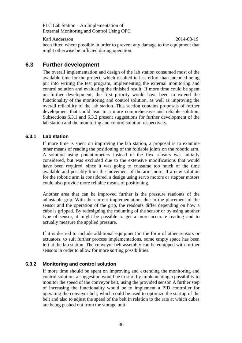
PLC Lab Station – An Implementation of
External Monitoring and Control Using OPC
Karl Andersson 2014-08-19
36
been fitted where possible in order to prevent any damage to the equipment that
might otherwise be inflicted during operation.
6.3 Further development
The overall implementation and design of the lab station consumed most of the
available time for the project, which resulted in less effort than intended being
put into writing the test program, implementing the external monitoring and
control solution and evaluating the finished result. If more time could be spent
on further development, the first priority would have been to extend the
functionality of the monitoring and control solution, as well as improving the
overall reliability of the lab station. This section contains proposals of further
development that could lead to a more comprehensive and reliable solution.
Subsections 6.3.1 and 6.3.2 present suggestions for further development of the
lab station and the monitoring and control solution respectively.
6.3.1 Lab station
If more time is spent on improving the lab station, a proposal is to examine
other means of reading the positioning of the foldable joints on the robotic arm.
A solution using potentiometers instead of the flex sensors was initially
considered, but was excluded due to the extensive modifications that would
have been required, since it was going to consume too much of the time
available and possibly limit the movement of the arm more. If a new solution
for the robotic arm is considered, a design using servo motors or stepper motors
could also provide more reliable means of positioning.
Another area that can be improved further is the pressure readouts of the
adjustable grip. With the current implementation, due to the placement of the
sensor and the operation of the grip, the readouts differ depending on how a
cube is gripped. By redesigning the mounting of the sensor or by using another
type of sensor, it might be possible to get a more accurate reading and to
actually measure the applied pressure.
If it is desired to include additional equipment in the form of other sensors or
actuators, to suit further process implementations, some empty space has been
left at the lab station. The conveyor belt assembly can be equipped with further
sensors in order to allow for more sorting possibilities.
6.3.2 Monitoring and control solution
If more time should be spent on improving and extending the monitoring and
control solution, a suggestion would be to start by implementing a possibility to
monitor the speed of the conveyor belt, using the provided sensor. A further step
of increasing the functionality would be to implement a PID controller for
operating the conveyor belt, which could be used to optimize the startup of the
belt and also to adjust the speed of the belt in relation to the rate at which cubes
are being pushed out from the storage unit.

PLC Lab Station – An Implementation of
External Monitoring and Control Using OPC
Karl Andersson 2014-08-19
37
Another suggestion for increasing the functionality of the monitoring and
control solution is to implement means of storing values from the analog
sensors, which could then be integrated with the simulation of the industrial
processes and used according to the OPC HDA specification. An example could
be to store the measurements from the load cell in order to keep statistics of the
weight of the objects, which could then be plotted into a graph over time to
clarify any variation in the measurements.
A more user friendly approach could be to use a separate PC for the OPC
server, which could be connected to the S7-400. This PC could then in turn be
accessed using the office network, making it possible for employees to use their
own PCs to run individual OPC clients with graphical user interfaces, allowing
for a more independent and manageable solution.
PLC Lab Station – An Implementation of
External Monitoring and Control Using OPC
Karl Andersson 2014-08-19
38
References Below is a complete list of the references that were used throughout the project:
[1] Process and Control Engineering, “Evolution of industrial control
systems”, http://www.pacetoday.com.au/features/evolution-of-industrial-
control-systems
Published 2013-12-04. Retrieved 2014-04-03.
[2] Automated Manufacturing Systems, “Programmable Logic Controllers”,
https://sites.google.com/site/automatedmanufacturingsystems/Home/plc
s
Published 2009-08-11. Retrieved 2014-04-18.
[3] MatrikonOPC, 2009: OPC: The Ins and Outs to What It’s About – The
Every Man’s Guide to OPC. Available at:
http://www.automation.com/pdf_articles/Guide_to_OPC.pdf
[4] ÅF Consult, “Company Information”,
http://www.afconsult.com/en/About-us/Company-Information/
Retrieved 2014-04-10.
[5] Siemens, “SIMATIC S7-300: the modular universal controller for the
manufacturing industry”, http://w3.siemens.com/mcms/programmable-
logic-controller/en/simatic-s7-controller/s7-300/Pages/Default.aspx
Retrieved 2014-07-28.
[6] Siemens, “SIMATIC S7-400 process controller: a powerful solution”,
http://w3.siemens.com/mcms/programmable-logic-controller/en/simatic-
s7-controller/s7-400/Pages/Default.aspx
Retrieved 2014-07-28.
[7] E. Estlind, “PLC Lab Station – Solution for Automatic Unloading of
Paper Reels”, Mid Sweden University, Sundsvall, 2014.
[8] J. Norberg, “PLC Lab Station – Simulating an Automatic Quality
Control of Loaf Products”, Mid Sweden University, Sundsvall, 2014.
[9] P. Zhang, Advanced Industrial Control Technology, 1st ed. Oxford:
Elsevier, 2010.
[10] Bosch Rexroth Corporation, 2009: Understanding the IEC61131-3
Programming Languages. Available at:
http://www.automation.com/pdf_articles/IEC_Programming_Thayer_L.

PLC Lab Station – An Implementation of
External Monitoring and Control Using OPC
Karl Andersson 2014-08-19
39
[11] OPC Foundation, “What is OPC?”,
https://opcfoundation.org/about/what-is-opc/
Retrieved 2014-04-14.
[12] OPC DataHub, “What is OPC?”,
http://www.opcdatahub.com/WhatIsOPC.html
Retrieved 2014-04-14.
[13] D. Reynders, S. Mackay, E. Wright, Practical Industrial Data
Communications – Best Practice Techniques, Oxford: Elsevier, 2005.
[14] HowStuffWorks, “How Automotive Production Lines Work – Modern
Automotive Production Lines”, http://auto.howstuffworks.com/under-
the-hood/auto-manufacturing/automotive-production-line3.htm
Retrieved 2014-04-03.
[15] Siemens, “Optimizing the automotive manufacturing process”,
http://www.industry.siemens.com/verticals/global/en/automotive-
manufacturing/process/Pages/Default.aspx
Retrieved 2014-04-03.
[16] HowStuffWorks, “How Automotive Production Lines Work – Recent
Changes to Automotive Production Lines”,
http://auto.howstuffworks.com/under-the-hood/auto-
manufacturing/automotive-production-line4.htm
Retrieved 2014-04-03.
[17] Design Build Network, “BMW Car Production Plant, Leipzig,
Germany”, http://www.designbuild-network.com/projects/bmw/
Retrieved 2014-04-03.
[18] Siemens, “Case Study – Process planning tools support Volvo Cars’
expansion to Asia Pacific region”,
http://www.plm.automation.siemens.com/se_se/about_us/success/case_s
tudy.cfm?Component=148707&ComponentTemplate=1481
Retrieved 2014-04-03.
[19] Velleman Components NV, 2003: DC to Pulse Width Modulator –
K8004. Available at:
http://www.electrokit.com/productFile/download/257
[20] Ifm Efector Inc, 2010: NF5004. Available at:
http://tds.ifm-electronic.com/tentacle/us/NF5004.pdf
[21] Panasonic: Cylindrical Photoelectric Sensor – CY-100 Series. Available
at: https://www1.elfa.se/data1/wwwroot/assets/datasheets/cy-
100_eng_tds.pdf
PLC Lab Station – An Implementation of
External Monitoring and Control Using OPC
Karl Andersson 2014-08-19
40
[22] Cebekit: Robot Arm Controlled by Cable-Kit C-9895. Available at:
https://www1.elfa.se/data1/wwwroot/assets/datasheets/c-
9895_1_eng_dts.pdf
[23] Elfa Distrelec, “Robotic arm kit, C-9895”,
https://www.elfa.se/elfa3~se_en/elfa/init.do?item=85-867-64
Retrieved 2014-07-08.
[24] Interlink Electronics: FSR 408 Data Sheet – FSR 400 Series Square
Force Sensing Resistor. Available at:
www.electrokit.com/productFile/download/5025
[25] Spectra Symbol: Flex Sensor FS. Available at:
www.electrokit.com/productFile/download/3181
[26] MaxBotix, 2012: HRLV-MaxSonar-EZ Series – High Resolution, Low
Voltage Ultra Sonic Range Finder. Available at:
www.electrokit.com/productFile/download/3053
[27] National Instruments, “The LabVIEW Equivalent of an “If” Statement”,
http://digital.ni.com/public.nsf/allkb/3B3D68F6EC5F2EFB8625694C00
654805
Published 2014-05-13. Retrieved 2014-06-12.
[28] Staudinger GmbH: Compact Transporting and Sorting Line. Available
at: http://www.staudinger-est.de/en/simulation/compact-
models/documents/226004.pdf
[29] Terco I&S AB, 2013: Processtyrning och Servosystem. Available at:
http://www.terco.se/wp-content/uploads/2009/09/Terco_Processtyrning-
Servosystem_SE_web.pdf

PLC Lab Station – An Implementation of
External Monitoring and Control Using OPC
Karl Andersson 2014-08-19
41
Appendix A: Design of 3D-printed plastic pulleys
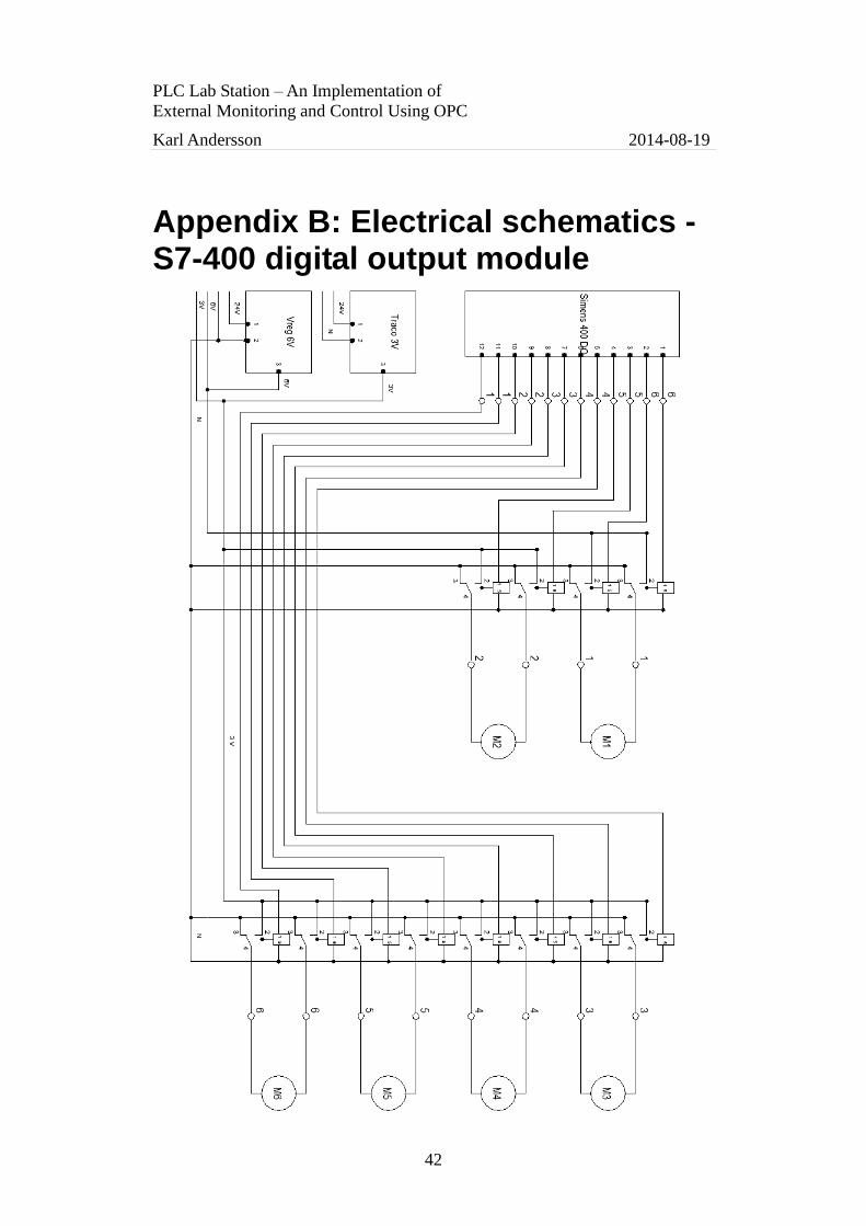
PLC Lab Station – An Implementation of
External Monitoring and Control Using OPC
Karl Andersson 2014-08-19
42
Appendix B: Electrical schematics - S7-400 digital output module

PLC Lab Station – An Implementation of
External Monitoring and Control Using OPC
Karl Andersson 2014-08-19
43
Appendix C: Electrical schematics - S7-300 digital input module

PLC Lab Station – An Implementation of
External Monitoring and Control Using OPC
Karl Andersson 2014-08-19
44
Appendix D: Electrical schematics - S7-300 digital output module

PLC Lab Station – An Implementation of
External Monitoring and Control Using OPC
Karl Andersson 2014-08-19
45
Appendix E: Electrical schematics - S7-300 analog input module

PLC Lab Station – An Implementation of
External Monitoring and Control Using OPC
Karl Andersson 2014-08-19
46
Appendix F: Electrical schematics - S7-300 analog output module
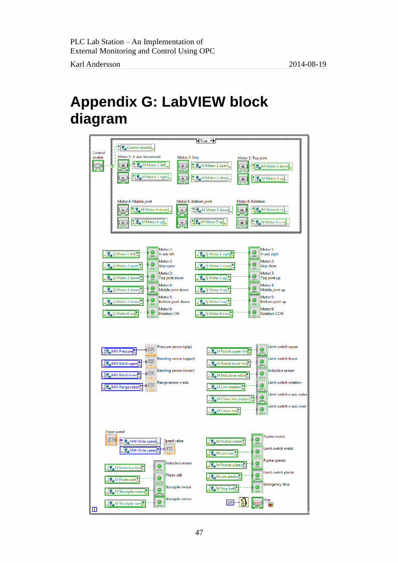
PLC Lab Station – An Implementation of
External Monitoring and Control Using OPC
Karl Andersson 2014-08-19
47
Appendix G: LabVIEW block diagram