Embed Size (px)
Citation preview

INCON FUEL MANAGEMENT SYSTEMS Inspection & Testing Presented By Matt Schuessler
Western Region Manager

Outline
1. Consoles. Model identification and testing. 2. Probes. Types, wiring, inspection, testing. 3. Sensors. Types, wiring, inspection, testing. 4. Electronic Line Leak Detection (ELLD). Model
identification and testing. 5. Accessories. Remote alarms. 6. Reports. Printing reports on various systems. 7. Resources. Where to get help.

1 - Consoles

Console Series Identification
INCON systems are comprised of the following series, newest to oldest: • Evo Fuel Management Systems. Extended T5
platform silver consoles with color touchscreen displays.
• Colibri. Compact grey console w color touchscreen but no printer, for in-tank (probe) use only.
• T5 Fuel Management Systems. Royal blue consoles with monochrome touchscreen display.
• T1 Tank Sentinel Systems. Black consoles with alphanumeric 2-line LCD display and membrane keypad. Models include TS-1001, 2001, 504/508, 750.
• TS-1000. First generation light blue console. No longer in production. (no photo)

T1 Series Functional Testing TS-504 (discontinued), TS-750, & TS-1001 Consoles • If console has a printer, verify it has paper. • Verify display is on and the date and time are correct. • Press Alarm Test button and verify WARNING and ALARM lights come
on and audible alarm sounds. • Identify and address any WARNINGS and ALARMS. Consult Tank
Sentinel Operator’s Guide for information. • Stick each tank and verify levels coincide with INCON tank levels. • Print Regulatory Report to confirm tanks, lines and sensors are
compliant (where applicable). • Print System Setup Report, then remove power using power switch.
Wait 10 seconds then restore power. If programming is lost the backup battery needs to be replaced.

T5 Series Functional Testing Colibri, TS-5/550/5000, TS-550/5000evo Consoles
• If console has a printer, verify it has paper.
• Verify display is on and the date and time are correct.
• Identify and address any WARNINGS and ALARMS. Consult Tank Sentinel Operator’s Guide for information.
• Stick each tank and verify that levels coincide with INCON tank levels.
• Print Regulatory Report to confirm tanks, lines and sensors are compliant (where applicable).
• Print System Setup Report, then remove power using power switch. After 10 seconds reapply power. If programming is lost the Controller Module needs to be replaced.

2 - Probes

Liquid Level Probes TSP-LL2-XX, TSP-LL2-XX-I Models
• Tank probes come in two models: ‘Precision’ which
can perform in-tank leak detection (i.e. tank testing for single-wall USTs) or Inventory-only.
• Probes use jacketed cables for communication. Inspect probe cables and connections. Replace any cracked, split, broken or swollen cables.
• Connections should be epoxy-sealed or in weatherproof junction boxes. Repair any connections showing corrosion, excessive moisture, or exposed bare wires.
• See Tank Sentinel or Fuel Management Systems Installation Guides for more information.

3 - Sensors
General Sensor Information
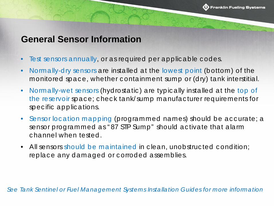
• Test sensors annually, or as required per applicable codes. • Normally-dry sensors are installed at the lowest point (bottom) of the
monitored space, whether containment sump or (dry) tank interstitial. • Normally-wet sensors (hydrostatic) are typically installed at the top of
the reservoir space; check tank/sump manufacturer requirements for specific applications.
• Sensor location mapping (programmed names) should be accurate; a sensor programmed as “87 STP Sump” should activate that alarm channel when tested.
• All sensors should be maintained in clean, unobstructed condition; replace any damaged or corroded assemblies.
See Tank Sentinel or Fuel Management Systems Installation Guides for more information
INCON Sensors & Part Numbers
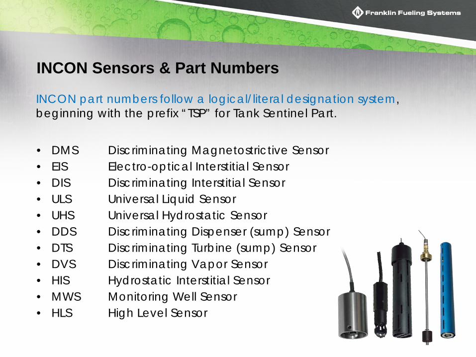
• DMS Discriminating Magnetostrictive Sensor • EIS Electro-optical Interstitial Sensor • DIS Discriminating Interstitial Sensor • ULS Universal Liquid Sensor • UHS Universal Hydrostatic Sensor • DDS Discriminating Dispenser (sump) Sensor • DTS Discriminating Turbine (sump) Sensor • DVS Discriminating Vapor Sensor • HIS Hydrostatic Interstitial Sensor • MWS Monitoring Well Sensor • HLS High Level Sensor
INCON part numbers follow a logical/literal designation system, beginning with the prefix “TSP” for Tank Sentinel Part.

Sensor Wiring TSP- DMS-12/24, EIS, DIS, ULS, UHS, DDS, DTS DVS, HIS, MWS, HLS Models
• Other than the Discriminating Mag Sensors (DMS), all sensors may be connected with stranded wire; DMS are probe-type devices therefore needing jacketed cable.
• Inspect sensor wiring and connections. Replace any cracked, split, broken or swollen wires.
• Connections should be epoxy-sealed or in weatherproof junction boxes. Repair any connections showing corrosion, excessive moisture, or exposed bare wires.
• Discriminating aka “Brite” sensors communicate using 3 wires; non-discriminating sensors use 2 wires.

Float Switch Sensors (non-discriminating)
• TSP-ULS Universal Liquid Sensor • Used to monitor sumps, wells, and dry tank
interstitial spaces. • To test, insert into container with at least three
inches of water (or the appropriate fuel when required) and verify LIQUID DETECTED ALARM trips.
• TSP-UHS Universal Hydrostatic Sensor • Similar to ULS but with inverted float for monitoring
normally-wet (liquid-filled) double-wall sump interstitial spaces.
• To test, lift the sensor from the reservoir and verify that SENSOR ALARM trips.
Float switch sensors are intended for vertical/upright orientation for proper operation

Optical Sensors
• Light-sensitive devices used in dark/enclosed spaces. Test in darkened/covered containers; light exposure may prevent activation.
• Include pull string eyelet for wraparound applications (i.e. dry DW fiberglass tank interstitial), and function in vertical or horizontal position.
• TSP-EIS Electro-optical Interstitial Sensor (non-discriminating) To test, insert sensor into darkened container with at least three inches of water (or the appropriate fuel when required) and verify that the LIQUID DETECTED alarm trips.
• TSP-DIS Discriminating Interstitial Sensor Insert sensor into darkened container with at least three inches of water (or the appropriate fuel when required) and verify that the WATER DETECTED or PRODUCT DETECTED alarm trips, as appropriate.
Wipe with clean, dry cloth before reinstallation.

Discriminating Sump Sensors
• Combined use of magnetic float switches to detect liquid at two levels, and polymer strip to detect hydrocarbons.
• TSP-DDS Discriminating Dispenser Sump Sensor (12”) • TSP-DTS Discriminating Turbine Sump Sensor (24”)
• Identical operation; DTS taller for deeper monitored spaces such as any tank sump (turbine, fill, piping, etc).
• To test, insert sensor into container with at least three inches of water (or the appropriate fuel when required) and verify WATER DETECTED or PRODUCT DETECTED alarm trips, as appropriate.
• Next, turn upside down or insert in several inches of water and verify that the SUMP FULL alarm trips.
Cleanse and dry after hydrocarbon exposure to return to service (recover)

Hydrostatic Interstitial Sensors
• Two internal float switches detect changes above or below full/normal tank interstitial reservoir level.
• TSP-DIS Discriminating Interstitial Sensor (12”) • TSP-DIS-XL Discriminating Interstitial Sensor (24”)
• To test, first verify brine level is filled to approximate middle of sensor body; adjust liquid or sensor positions as necessary.
• Remove from interstitial brine solution and verify LOW BRINE alarm trips.
• Next, fully submerge in interstitial brine solution and verify HIGH BRINE alarm trips.

TSP-MWS Monitoring Well Sensor
• Discriminating, normally-wet, groundwater monitoring well sensor which detects hydrocarbons anywhere along its length.
• Hangs suspended from top well cap/plug; available in 10’, 15’, 20’ and 25’ lengths.
• To test, remove sensor and verify DRY WELL alarm trips.
• Where required, insert into appropriate fuel and verify PRODUCT DETECTED alarm trips.

TSP-DVS Discriminating Vapor Sensor
• Discriminating, normally-dry sensor which detects hydrocarbon vapors in monitoring well or other containment space.
• To test, first place in high-vapor environment such as a mostly empty gasoline container and confirm VAPOR DETECTED alarm trips.
• Next, remove to open air; vapor reading will drop.
• Finally, insert into container with at least three inches of water and confirm WATER DETECTED alarm trips.
A wet sensor will not detect vapors

High Level/Overfill Sensors
• Rigid shaft, adjustable position float switch sensor; available in two lengths:
• TSP-HLS-15 High Level Sensor (15”) • TSP-HLS-30 High Level Sensor (30”)
• To test, manually move the float to raised/high level
position and verify LIQUID DETECTED alarm trips.

Magnetostrictive (MAG) Sensors
• Miniaturized probe-type device which detects water and hydrocarbons, indicates water level in inches, and will alarm if removed from installed (normal) position.
• TSP-DMS-12 Discriminating Mag Sensor (12”) • TSP-DMS-24 Discriminating Mag Sensor (24”) • To test, raise slightly off containment base and verify MAG
SENSOR INSTALLATION ERROR trips. • Place onto bottom of container with three inches of water
and verify MAG WATER warning trips. • Place onto bottom of container with three inches of fuel
and verify MAG PRODUCT Alarm trips. • Reinstall into original location, ensuring DMS sits at bottom
of containment space and verify no alarms or warnings remain.

4 - Electronic Line Leak Detection (ELLD)

TS-LLD Line Leak Detector
• Single-channel explosion-proof (retrofit) standalone ELLD using plenum gold transducers which communicate over STP power circuit.
• Confirm no active alarms; if present, check dispenser and submersible pump sumps for leaks.
• To test, introduce calibrated 3 GPH leak into product line and manually launch a Gross Test (3 GPH); verify controller completes test and indicates a flashing “3” and LINE LEAK DETECTED.
• Verify dispensing disabled while in Gross Alarm. • Press RESET/TEST button to restore normal system
operation after simulated leak is detected. Consult TS-LLD Installation Guide for specific instructions.

TS-LS300 AutoLearn Line Leak Detector
• 4-channel standalone or sidecar ELLD using gold transducers.
• To test, print Regulatory Report on INCON to confirm Monthly Line Tests (.2 GPH) are passing each month (when integrated with T1 Series).
• Confirm no active line alarms; if present, check dispenser and submersible pump sumps for leaks.
• Introduce calibrated 3 GPH leak into product line and manually launch a Gross Test (3 GPH); verify system completes test and indicates Gross Alarm.
• Verify dispensing disabled while in Gross Alarm.
Consult TS-LS300 AutoLearn User’s Guide for specific instructions.

TS-LS500 AutoLearn Line Leak Detector
• T5 series integrated ELLD using blue transducers. • To test, print Regulatory Report to confirm Monthly
Line Tests (.2 GPH) are passing each month. • Confirm no active line alarms; if present, check
dispenser and submersible pump sumps for leaks. • Introduce calibrated 3 GPH leak into product line
and manually launch a Gross Test (3 GPH); verify system completes test and indicates Gross Alarm.
• Verify dispensing disabled while in Gross Alarm.
Consult TS-LS500 AutoLearn User’s Guide for specific instructions.

5 - Accessories

Remote/Overfill Alarms
• Enclosed external alarm stations for remote notification of overfill threat. Can also be used for other alarms if desired, dependent upon system configuration.
• TS-RA1 Remote Alarm (indoor or outdoor) • TS-RA2 High-Intensity Remote Alarm (outdoor) • TS-RK Remote Acknowledgement Button • To test, remove tank probe then slide product float to a HIGH HIGH
level position, based on system setup. Confirm HIGH HIGH alarm on console, and audible and visual alarm on remote unit(s).
• Press acknowledgement button to clear remote unit.

6 - Report Printing

Printing Reports (T1 Series)
• Press the REPORT key.
• Press the DOWN key to view report types.
• Press M1-M4 menu softkeys to make report choice.

Printing Reports (T5/Colibri Series)
• Press to access the Report Menu.
• Select the Report Type and Date Range desired.

Printing Reports (Evo Series)
• Press the down arrow at
the top of the screen to open the Quick Jump Menu.
• Press to access the Report Menu.
• Select the Report Type and Date Range desired.
• Select the output method (print, email, fax).

Resources
• Website. www.franklinfueling.com Product info, catalogs, datasheets, manuals.
• TECHLAB. http://techlab.franklinfueling.com Technical extranet site. Check contractor certifications, register for online or classroom training, download manuals, CAD drawings, watch videos, etc.
• Helpdesk. Mon – Fri 8A to 5P all CONUS time zones. 800-984-6266.
• Regional Field Service Engineers. Instruction, technical field support, and on-site assistance when needed.
• Northeast Steve Nelson [email protected] 734-854-2026 • Southeast Loren Swalheim [email protected] 608-354-5175 • Midwest Doug Wanless [email protected] 608-698-7310 • Southwest Alex Molina [email protected] 608-280-1958 • West John Covington [email protected] 805-434-7329