Embed Size (px)
Citation preview
HTC 2015
HORIZONTAL DIRECTIONAL DRILLING AND WELL
INSTALLATION AT SMALL SITES
History of Horizontal Environmental Wells• Horizontal/Directional Oil Wells in the 1930s – Present
• Directional “River Crossings” in the 1970s
• Environmental Applications for the Department of
Energy in 1988
• Utilized for Most Remediation Applications by 2015
Environmental Applications• Sampling under
obstructions
• Extraction techniques– Groundwater
– Free phase product –NAPL and DNAPL
– Vapors
– Dual phase
• Injection techniques– ISCO
– Nutrient injection
– Air sparge
– Bio sparge
– Barriers – PRBs/HRx
• Thermal treatment
– Hot air/steam injection
– Electrical resistance
heating
• Dewatering
• Slope stability
• Mine tailings
• Ground water
production
Applications/Advantages of Horizontal WellsThree Major Advantages
• Geometry
• Access areas unreachable to vertical wells
• Minimal site impact
Directional Control
• The bit is navigated along a prescribed path
• The well need not be horizontal
• Bore path is design is based on
– Allowable bending radius of drill pipe and well materials
– Geology
– Treatment objective
– Surface constraints
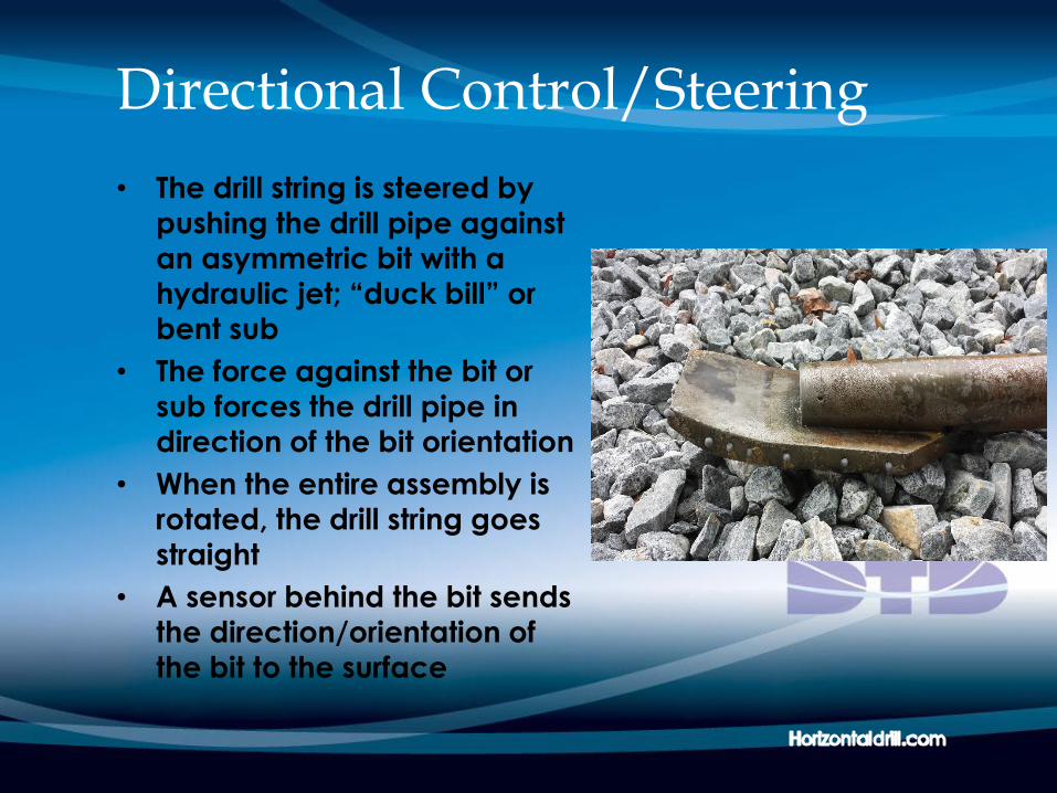
Directional Control/Steering
• The drill string is steered by pushing the drill pipe against
an asymmetric bit with a
hydraulic jet; “duck bill” or
bent sub
• The force against the bit or
sub forces the drill pipe in
direction of the bit orientation
• When the entire assembly is rotated, the drill string goes
straight
• A sensor behind the bit sends
the direction/orientation of
the bit to the surface
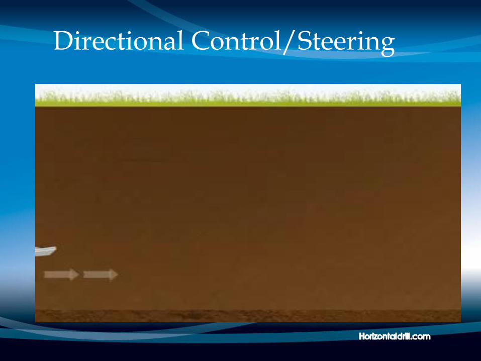
Directional Control/Steering
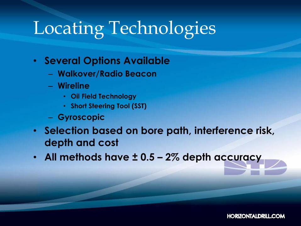
Locating Technologies
• Several Options Available
– Walkover/Radio Beacon
– Wireline• Oil Field Technology
• Short Steering Tool (SST)
– Gyroscopic
• Selection based on bore path, interference risk,
depth and cost
• All methods have ± 0.5 – 2% depth accuracy
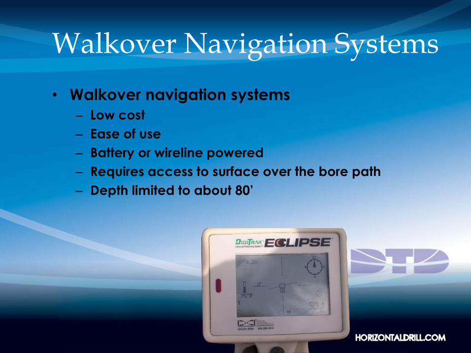
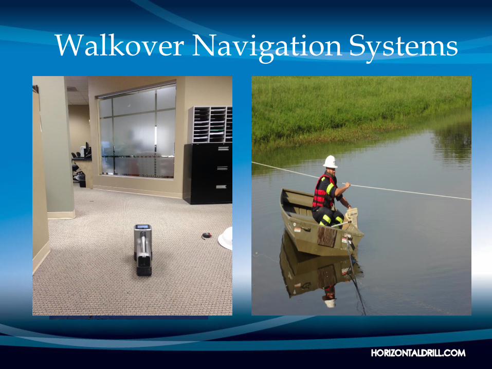
Walkover Navigation Systems
• Walkover navigation systems
– Low cost
– Ease of use
– Battery or wireline powered
– Requires access to surface over the bore path
– Depth limited to about 80’
Walkover Navigation Systems
Drilling Fluids are Required
• Maintain hole stability
• Remove cuttings
• Limit drilling fluid loss to the formation
• Cool bit and steering tools
• Two types commonly utilized
– Bentonite
– Biodegradable polymer
Well Materials (Screen & Casing)
• Similar materials to vertical well installations
– PVC
– Carbon steel
– Stainless steel (304 and 316L)
– HDPE
– Fiberglass
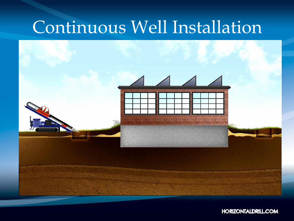
Continuous Well Installation
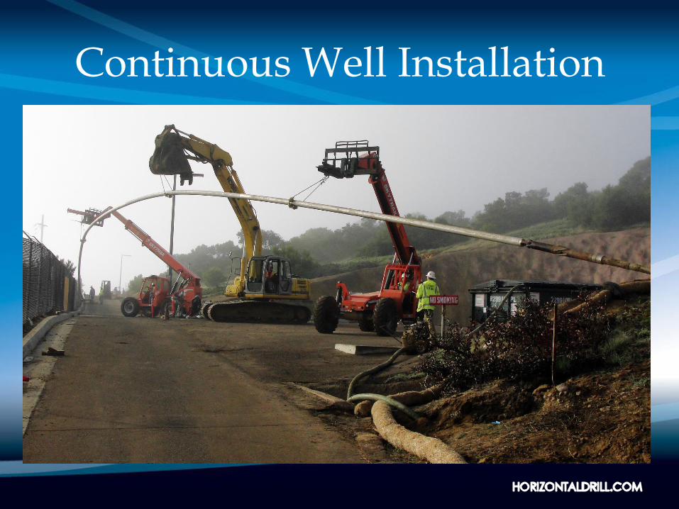
Continuous Well Installation
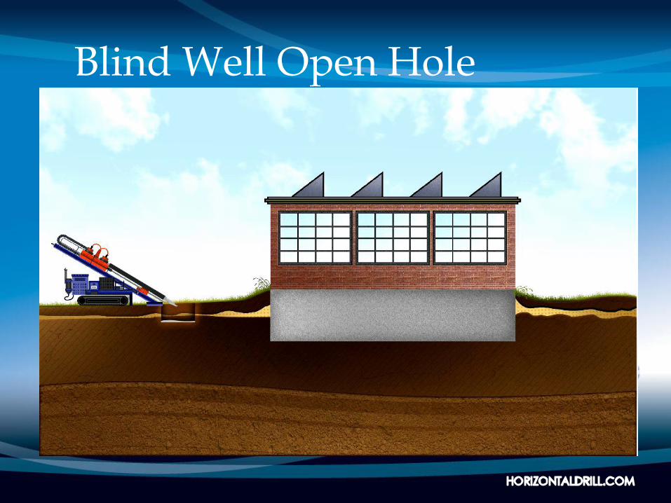
Blind Well Open Hole
Borepath/Well Geometry
• Terminology
– Entry angle
– Tangent
– Radius of curvature (build radius)
– Horizontal section
– True vertical depth
– Measured depth/pipe length
– Set back – determined by combination
of the above
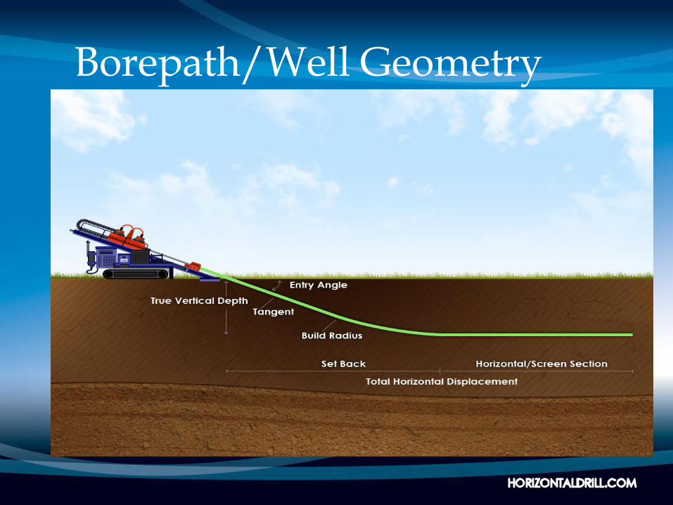
Borepath/Well Geometry
Drilling Equipment
• Drill rig
• Fluid cleaning/recycling system
• Pipe trailer
• Support vehicles
– Water truck
– Crew truck
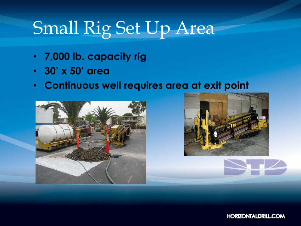
Small Rig Set Up Area
• 7,000 lb. capacity rig
• 30’ x 50’ area
• Continuous well requires area at exit point
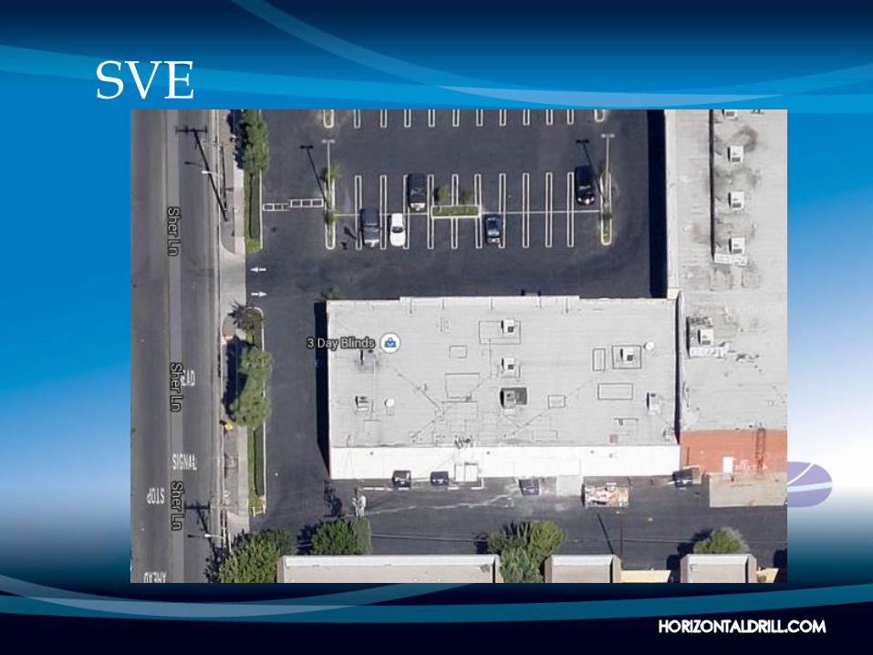
Sparge/SVE
• Former dry cleaning facility, Los Angeles Basin
• Active retail site
• Contaminant mass in soil and groundwater
under building
• Remedy could not impact ongoing operations
• Original plan included 20 vertical wells –
businesses closed for 60 days for construction
• Horizontal wells to the rescue
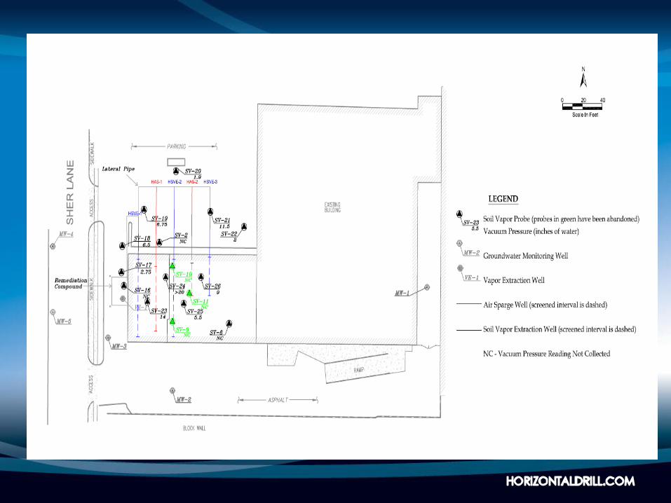
Sparge/SVE
• Original design called for continuous wells
– Three SVE
– Two sparge
• Site constraints altered design
• Blind well technology was utilized
– Three SVE wells: 99’ long, 4’ deep, 2” sch. 80 PVC
– Two sparge wells: 99’ long, 11’ deep, 2” sch. 80 PVC
SVE
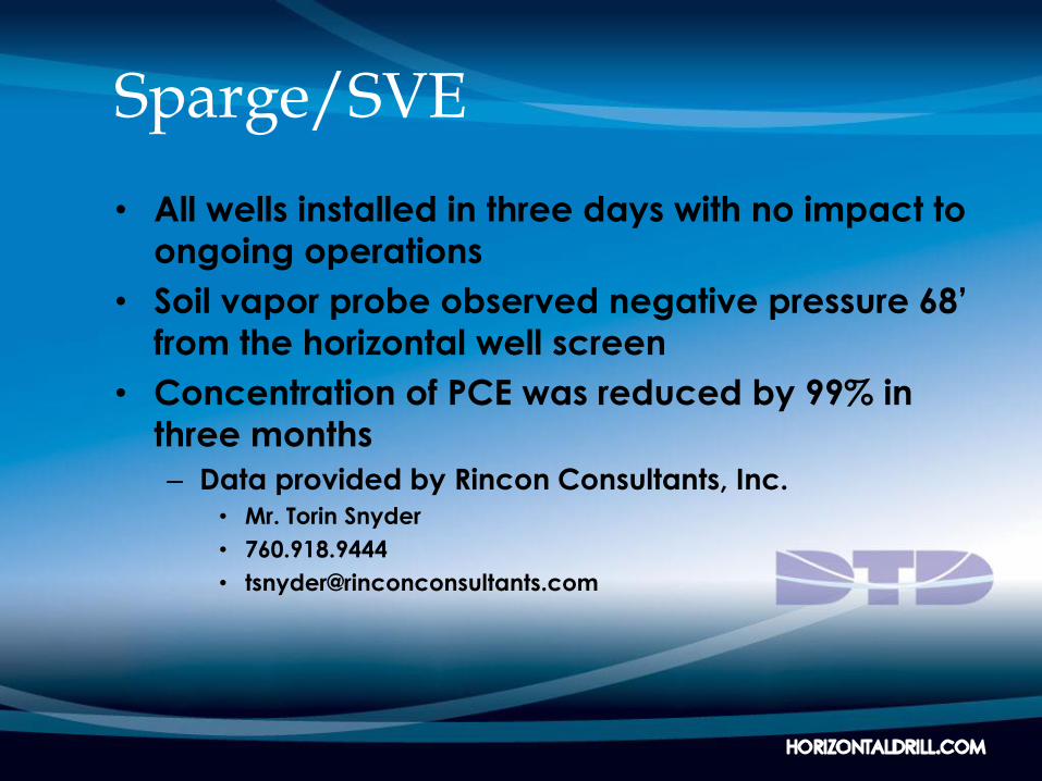
Sparge/SVE
• All wells installed in three days with no impact to
ongoing operations
• Soil vapor probe observed negative pressure 68’
from the horizontal well screen
• Concentration of PCE was reduced by 99% in
three months
– Data provided by Rincon Consultants, Inc.• Mr. Torin Snyder
• 760.918.9444
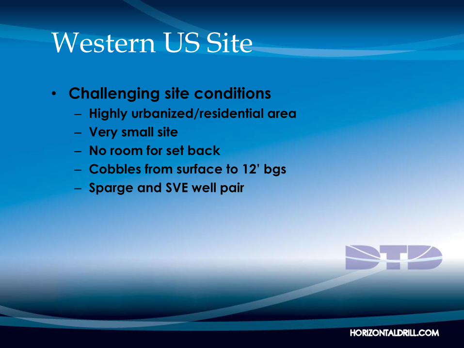
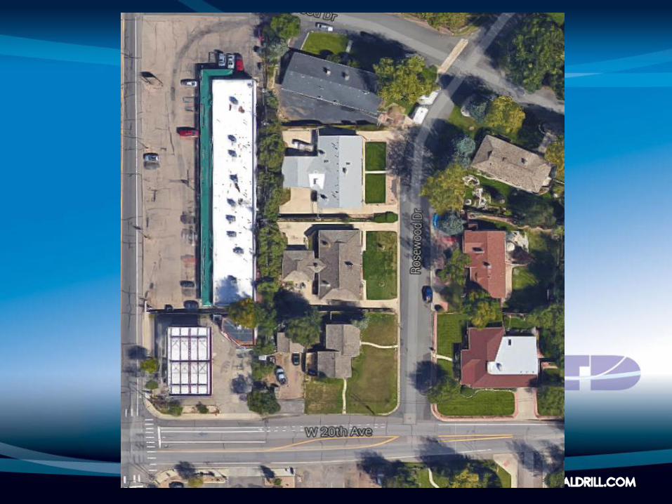
Western US Site
• Challenging site conditions
– Highly urbanized/residential area
– Very small site
– No room for set back
– Cobbles from surface to 12’ bgs
– Sparge and SVE well pair
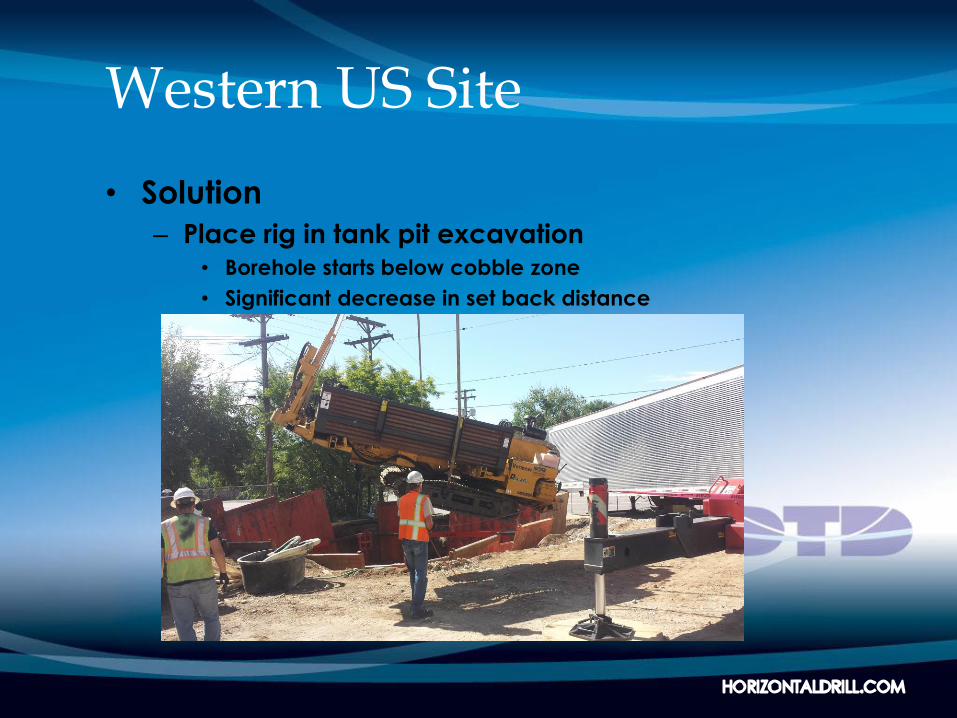
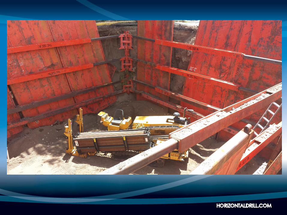
Western US Site
• Solution
– Place rig in tank pit excavation• Borehole starts below cobble zone
• Significant decrease in set back distance

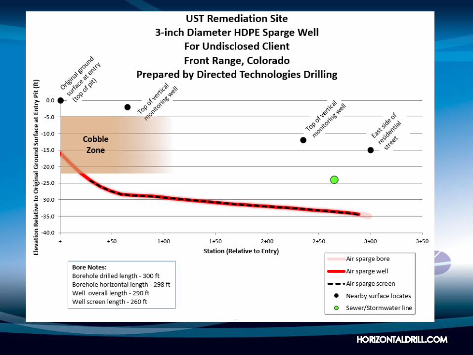
Western US Site
• Creative Thinking Overcame Site Challenges
• Total of 255’ of drilling
• Seven rig days
• Cost for drilling and well installation
– $85,000
– $153/ft.
– Costs do not include excavation, shoring and waste
containment and disposal
In Summary
• The technology is innovative - not experimental
• Horizontal wells are a proven, cost effective
installation method
• Thousands of wells have been successfully
completed in the US
• Horizontal wells can be used with all remediation
technologies
• The technology is innovative – not experimental