Embed Size (px)
Citation preview
68-791-01 Rev. H12 10
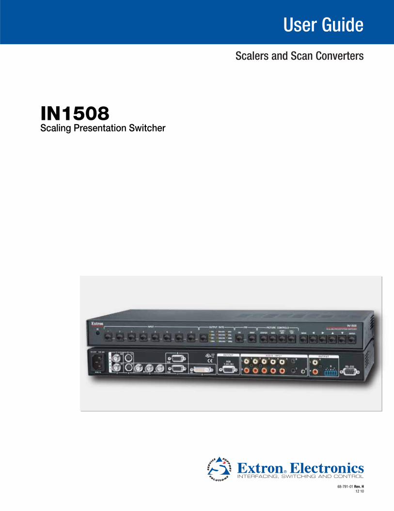
Scaling Presentation SwitcherIN1508
User Guide
Scalers and Scan Converters
This symbol is intended to alert the user of important operating and mainte-nance (servicing) instructions in the literature provided with the equipment.
This symbol is intended to alert the user of the presence of uninsulated dangerous voltage within the product’s enclosure that may present a risk of electric shock.
CautionRead Instructions • Read and understand all safety and operating instructions before using the equipment.
Retain Instructions • The safety instructions should be kept for future reference.
Follow Warnings • Follow all warnings and instructions marked on the equipment or in the user information.
Avoid Attachments • Do not use tools or attachments that are not recommended by the equipment manufacturer because they may be hazardous.
WarningPower sources • This equipment should be operated only from the power source indicated on the product. This
equipment is intended to be used with a main power system with a grounded (neutral) conductor. The third (grounding) pin is a safety feature, do not attempt to bypass or disable it.
Power disconnection • To remove power from the equipment safely, remove all power cords from the rear of the equipment, or the desktop power module (if detachable), or from the power source receptacle (wall plug).
Power cord protection • Power cords should be routed so that they are not likely to be stepped on or pinched by items placed upon or against them.
Servicing • Refer all servicing to qualified service personnel. There are no user-serviceable parts inside. To prevent the risk of shock, do not attempt to service this equipment yourself because opening or removing covers may expose you to dangerous voltage or other hazards.
Slots and openings • If the equipment has slots or holes in the enclosure, these are provided to prevent overheating of sensitive components inside. These openings must never be blocked by other objects.
Lithium battery • There is a danger of explosion if battery is incorrectly replaced. Replace it only with the same or equivalent type recommended by the manufacturer. Dispose of used batteries according to the manufacturer’s instructions.
Ce symbole sert à avertir l’utilisateur que la documentation fournie avec le matériel contient des instructions importantes concernant l’exploitation et la maintenance (réparation).
Ce symbole sert à avertir l’utilisateur de la présence dans le boîtier de l’appareil de tensions dangereuses non isolées posant des risques d’électrocution.
AttentionLire les instructions• Prendre connaissance de toutes les consignes de sécurité et d’exploitation avant
d’utiliser le matériel.
Conserver les instructions• Ranger les consignes de sécurité afin de pouvoir les consulter à l’avenir.
Respecter les avertissements • Observer tous les avertissements et consignes marqués sur le matériel ou présentés dans la documentation utilisateur.
Eviter les pièces de fixation • Ne pas utiliser de pièces de fixation ni d’outils non recommandés par le fabricant du matériel car cela risquerait de poser certains dangers.
AvertissementAlimentations • Ne faire fonctionner ce matériel qu’avec la source d’alimentation indiquée sur l’appareil. Ce
matériel doit être utilisé avec une alimentation principale comportant un fil de terre (neutre). Le troisième contact (de mise à la terre) constitue un dispositif de sécurité : n’essayez pas de la contourner ni de la désactiver.
Déconnexion de l’alimentation• Pour mettre le matériel hors tension sans danger, déconnectez tous les cordons d’alimentation de l’arrière de l’appareil ou du module d’alimentation de bureau (s’il est amovible) ou encore de la prise secteur.
Protection du cordon d’alimentation • Acheminer les cordons d’alimentation de manière à ce que personne ne risque de marcher dessus et à ce qu’ils ne soient pas écrasés ou pincés par des objets.
Réparation-maintenance • Faire exécuter toutes les interventions de réparation-maintenance par un technicien qualifié. Aucun des éléments internes ne peut être réparé par l’utilisateur. Afin d’éviter tout danger d’électrocution, l’utilisateur ne doit pas essayer de procéder lui-même à ces opérations car l’ouverture ou le retrait des couvercles risquent de l’exposer à de hautes tensions et autres dangers.
Fentes et orifices • Si le boîtier de l’appareil comporte des fentes ou des orifices, ceux-ci servent à empêcher les composants internes sensibles de surchauffer. Ces ouvertures ne doivent jamais être bloquées par des objets.
Lithium Batterie • Il a danger d’explosion s’ll y a remplacment incorrect de la batterie. Remplacer uniquement avec une batterie du meme type ou d’un ype equivalent recommande par le constructeur. Mettre au reut les batteries usagees conformement aux instructions du fabricant.
Safety Instructions • English
Consignes de Sécurité • Français
Sicherheitsanleitungen • DeutschDieses Symbol soll dem Benutzer in der im Lieferumfang enthaltenen Dokumentation besonders wichtige Hinweise zur Bedienung und Wartung (Instandhaltung) geben.
Dieses Symbol soll den Benutzer darauf aufmerksam machen, daß im Inneren des Gehäuses dieses Produktes gefährliche Spannungen, die nicht isoliert sind und die einen elektrischen Schock verursachen können, herrschen.
AchtungLesen der Anleitungen • Bevor Sie das Gerät zum ersten Mal verwenden, sollten Sie alle Sicherheits-und
Bedienungsanleitungen genau durchlesen und verstehen.
Aufbewahren der Anleitungen • Die Hinweise zur elektrischen Sicherheit des Produktes sollten Sie aufbewahren, damit Sie im Bedarfsfall darauf zurückgreifen können.
Befolgen der Warnhinweise • Befolgen Sie alle Warnhinweise und Anleitungen auf dem Gerät oder in der Benutzerdokumentation.
Keine Zusatzgeräte • Verwenden Sie keine Werkzeuge oder Zusatzgeräte, die nicht ausdrücklich vom Hersteller empfohlen wurden, da diese eine Gefahrenquelle darstellen können.
VorsichtStromquellen • Dieses Gerät sollte nur über die auf dem Produkt angegebene Stromquelle betrieben werden.
Dieses Gerät wurde für eine Verwendung mit einer Hauptstromleitung mit einem geerdeten (neutralen) Leiter konzipiert. Der dritte Kontakt ist für einen Erdanschluß, und stellt eine Sicherheitsfunktion dar. Diese sollte nicht umgangen oder außer Betrieb gesetzt werden.
Stromunterbrechung • Um das Gerät auf sichere Weise vom Netz zu trennen, sollten Sie alle Netzkabel aus der Rückseite des Gerätes, aus der externen Stomversorgung (falls dies möglich ist) oder aus der Wandsteckdose ziehen.
Schutz des Netzkabels • Netzkabel sollten stets so verlegt werden, daß sie nicht im Weg liegen und niemand darauf treten kann oder Objekte darauf- oder unmittelbar dagegengestellt werden können.
Wartung • Alle Wartungsmaßnahmen sollten nur von qualifiziertem Servicepersonal durchgeführt werden. Die internen Komponenten des Gerätes sind wartungsfrei. Zur Vermeidung eines elektrischen Schocks versuchen Sie in keinem Fall, dieses Gerät selbst öffnen, da beim Entfernen der Abdeckungen die Gefahr eines elektrischen Schlags und/oder andere Gefahren bestehen.
Schlitze und Öffnungen • Wenn das Gerät Schlitze oder Löcher im Gehäuse aufweist, dienen diese zur Vermeidung einer Überhitzung der empfindlichen Teile im Inneren. Diese Öffnungen dürfen niemals von anderen Objekten blockiert werden.
Litium-Batterie • Explosionsgefahr, falls die Batterie nicht richtig ersetzt wird. Ersetzen Sie verbrauchte Batterien nur durch den gleichen oder einen vergleichbaren Batterietyp, der auch vom Hersteller empfohlen wird. Entsorgen Sie verbrauchte Batterien bitte gemäß den Herstelleranweisungen.
Este símbolo se utiliza para advertir al usuario sobre instrucciones impor-tantes de operación y mantenimiento (o cambio de partes) que se desean destacar en el contenido de la documentación suministrada con los equipos.
Este símbolo se utiliza para advertir al usuario sobre la presencia de elemen-tos con voltaje peligroso sin protección aislante, que puedan encontrarse dentro de la caja o alojamiento del producto, y que puedan representar riesgo de electrocución.
PrecaucionLeer las instrucciones • Leer y analizar todas las instrucciones de operación y seguridad, antes de usar el
equipo.
Conservar las instrucciones • Conservar las instrucciones de seguridad para futura consulta.
Obedecer las advertencias • Todas las advertencias e instrucciones marcadas en el equipo o en la documentación del usuario, deben ser obedecidas.
Evitar el uso de accesorios • No usar herramientas o accesorios que no sean especificamente recomendados por el fabricante, ya que podrian implicar riesgos.
AdvertenciaAlimentación eléctrica • Este equipo debe conectarse únicamente a la fuente/tipo de alimentación eléctrica
indicada en el mismo. La alimentación eléctrica de este equipo debe provenir de un sistema de distribución general con conductor neutro a tierra. La tercera pata (puesta a tierra) es una medida de seguridad, no puentearia ni eliminaria.
Desconexión de alimentación eléctrica • Para desconectar con seguridad la acometida de alimentación eléctrica al equipo, desenchufar todos los cables de alimentación en el panel trasero del equipo, o desenchufar el módulo de alimentación (si fuera independiente), o desenchufar el cable del receptáculo de la pared.
Protección del cables de alimentación • Los cables de alimentación eléctrica se deben instalar en lugares donde no sean pisados ni apretados por objetos que se puedan apoyar sobre ellos.
Reparaciones/mantenimiento • Solicitar siempre los servicios técnicos de personal calificado. En el interior no hay partes a las que el usuario deba acceder. Para evitar riesgo de electrocución, no intentar personalmente la reparación/mantenimiento de este equipo, ya que al abrir o extraer las tapas puede quedar expuesto a voltajes peligrosos u otros riesgos.
Ranuras y aberturas • Si el equipo posee ranuras o orificios en su caja/alojamiento, es para evitar el sobrecalientamiento de componentes internos sensibles. Estas aberturas nunca se deben obstruir con otros objetos.
Batería de litio • Existe riesgo de explosión si esta batería se coloca en la posición incorrecta. Cambiar esta batería únicamente con el mismo tipo (o su equivalente) recomendado por el fabricante. Desachar las baterías usadas siguiendo las instrucciones del fabricante.
Instrucciones de seguridad • Español
安全须知 • 中文这个符号提示用户该设备用户手册中有重要的操作和维护说明。
这个符号警告用户该设备机壳内有暴露的危险电压,有触电危险。
注意阅读说明书 • 用户使用该设备前必须阅读并理解所有安全和使用说明。
保存说明书 • 用户应保存安全说明书以备将来使用。
遵守警告 • 用户应遵守产品和用户指南上的所有安全和操作说明。
避免追加 • 不要使用该产品厂商没有推荐的工具或追加设备,以避免危险。
警告电源 • 该设备只能使用产品上标明的电源。 设备必须使用有地线的供电系统供电。 第三条线
(地线)是安全设施,不能不用或跳过 。
拔掉电源 • 为安全地从设备拔掉电源,请拔掉所有设备后或桌面电源的电源线,或任何接到市电系统的电源线。
电源线保护 • 妥善布线, 避免被踩踏,或重物挤压。
维护 • 所有维修必须由认证的维修人员进行。 设备内部没有用户可以更换的零件。为避免出现触电危险不要自己试图打开设备盖子维修该设备。
通风孔 • 有些设备机壳上有通风槽或孔,它们是用来防止机内敏感元件过热。 不要用任何东西挡住通风孔。
锂电池 • 不正确的更换电池会有爆炸的危险。必须使用与厂家推荐的相同或相近型号的电池。按照生产厂的建议处理废弃电池。
FCC Class A Notice
This equipment has been tested and found to comply with the limits for a Class A digital device, pursuant to part 15 of the FCC Rules. Operation is subject to the following two conditions:
1. This device may not cause harmful interference.
2. This device must accept any interference received, including interference that may cause undesired operation.
The Class A limits are designed to provide reasonable protection against harmful interference when the equipment is operated in a commercial environment. This equipment generates, uses, and can radiate radio frequency energy and, if not installed and used in accordance with the instruction manual, may cause harmful interference to radio commu-nications. Operation of this equipment in a residential area is likely to cause harmful interference, in which case the user will be required to correct the interference at his own expense.
NOTE: This unit was tested with shielded cables on the peripheral devices. Shielded cables must be used with the unit to ensure compliance with FCC emissions limits. For more information on safety guidelines, regulatory compliances, EMI/EMF compliance, accessibility, and related topics, click here.
Notational Conventions Used in this Guide
TIP: A tip provides a suggestion to make setting up or working with the device easier.
NOTE: A note draws attention to important information.
CAUTION: A caution warns of things or actions that might damage the equipment.
WARNING: A warning warns of things or actions that might cause injury, death, or other severe consequences.
Copyright© 2010 Extron Electronics. All rights reserved.TrademarksAll trademarks mentioned in this guide are the properties of their respective owners.
Contents
Introduction ............................................ 1
About this Guide ............................................. 1About the Switcher .......................................... 2
DVI Video .................................................... 3Features ........................................................... 4
Installation .............................................. 6
Cabling and Rear Panel Views .......................... 6Power Connection ....................................... 6Video Connections ....................................... 6Audio Connections ...................................... 7RS-232 Connection ...................................... 8
Remote Control Battery Installation .................. 8Configuration .................................................. 8
Operation ................................................ 9
Front Panel Controls and Indicators .................. 9Infrared Sensor............................................. 9Input Controls ............................................ 10Output Rate Selection ................................ 11Picture-in-Picture Controls .......................... 12Picture Controls Buttons ............................. 13Menu Control Buttons ............................... 14
Remote Control Buttons ................................ 15Operations ..................................................... 17
Power ........................................................ 17Input Selection Operation .......................... 18Picture-in-picture Mode Operation ............. 18Menu System Operation ............................ 20Main Menu System .................................... 24Performing a System Reset from the Front Panel ................................. 33
Picture Adjustments ................................... 34Front Panel Security Lockout (Executive Mode 1) ................................... 38
Optimizing the Video ..................................... 38Setting up a DVD Source ............................ 38Resolution and Refresh Rates ..................... 38Selecting the Optimum Resolution and Refresh Rate for Fixed Pixel Displays ... 39
Input Submenu > Advanced Selections ...... 40
Optimizing the Audio..................................... 46Troubleshooting ............................................. 46
General Checks .......................................... 46Specific Problems ....................................... 47
Programming Guide ..............................51
RS-232 Port ................................................... 51Host-to-Switcher Instructions ......................... 51Switcher-Initiated Messages ........................... 52Switcher Error Responses ............................... 52Using the Command/Response Tables ............ 52
Symbol Definitions ..................................... 53Command/response Table for Special Function SIS Commands ................ 58
Reference Information ..........................61
Specifications ................................................. 61Part Numbers ................................................. 64
IN508 Part Numbers ................................... 64Suggested Adapters ................................... 64Cables ....................................................... 64
Rack Mounting .............................................. 65Tabletop Use .............................................. 65Rack Mounting .......................................... 65
IN1508 • Contents iii

IN1508 • Contents iv

Introduction
• About this Guide
• About the Switcher
• Features
About this GuideThis guide contains installation, configuration, and operating information for the Extron IN1508 Scaling Presentation Switcher (referred to in this manual as the “IN1508” or the “switcher”) (see figure 1).
100-240V 50-60Hz I
N
P
U
T
VID
VID
YC
Y
B-Y
R-Y
RGB
DVI
1
2
4
5
3
L
2
3
4
5
6
7
R
AUDIO INPUT
L
A
B
R
OUTPUT
L
R
OUTPUT
RGB
Y, B-Y, R
-Y
8
7
RGB
6
LISTED
1T23
I.T.E.
C
U S
1 XPA 1002
12
LIMITER/PROTECT
SIGNAL
OVER
TEMP
ON
OFF
DISPLAY
MUTE
SCREEN
UP
SCREEN
DOWN
VCR
DVD
DOC
CAM
LAPTOP
PC
1
31
42
31
42
31
42
2
3
100
LINK
ACT
COM
IR
INPUTRELAY
TXRX
R
IPL 250
®
ExtronSI 28Surface-mountSpeakers
ExtronXPA 1002Audio PowerAmpli�er
VCRDocumentCamera
LCD Projector
Laptop
DVD Player
PC
ExtronIN1508Scaling PresentationSwitcher
PCDVI Output
RS-232
TCP/IP
TouchLink™Control System
Figure 1. Typical IN1508 Scaling Presentation Switcher Application
IN1508 • Introduction 1

About the SwitcherThe Extron IN1508 is an eight-input video and stereo audio switcher that incorporates a video scaler. The switcher accepts:
• Two NTSC/PAL/SECAM/NTSC 4.43 composite video inputs on female BNC connectors
• Two S-video (Y/C) inputs on 4-pin mini DIN connectors
• One component (YUV) video input (progressive [Y, B-Y, R-Y] or interlaced [Y, B-Y, R-Y]) on female BNC connectors
• Two VGA – UXGA (RGBHV or RGBS) inputs on 15-pin HD connectors
• One digital visual interface (DVI), direct digital input on a DVI-I female connector with EDID emulation (see “DVI Video” on page 3 for an introduction to the DVI video format)
NOTE: With the proper adapters, the IN1508 can also be used with non-HDCP High Definition Multimedia Interface (HDMI®) signals.
• Eight unbalanced stereo or mono audio inputs (five inputs on RCA connectors and three inputs on 3.5 mm mini stereo jacks)
The IN1508 scales the video inputs to a variety of standard VGA and HDTV resolutions and any of up to 3 available refresh rates. The switcher outputs RGBHV, RGBS, RGsB, or progressive component (Y, B-Y, R-Y) video on a 15-pin HD (VGA) connector. It outputs stereo or mono audio on left and right RCA connectors and a 3.5 mm 5-pole captive screw connector. The IN1508 allows all of the input formats listed above to be displayed on a device with a fixed resolution and aspect ratio, such as a liquid crystal display (LCD) projector, digital light processor (DLP) projector, or plasma display.
The IN1508 seamlessly switches between the VGA and low-resolution video inputs. Seamless switching allows switching between sources without a loss of sync.
The scaler in the switcher upscales or downscales, converting the horizontal and vertical sync timing and the number of lines of the video input to match the native resolution of the display. This produces an undistorted, brighter picture.
The switcher is housed in a 1U high, 17.5 inch wide metal enclosure. With the included mounting ears, the switcher is rack-mountable. With optional mounting hardware, the switcher can be mounted under or through furniture or other mounting surface. The switcher has an internal 100 VAC to 240 VAC, 50/60 Hz, 40 watts, power supply that provides worldwide power compatibility.
IN1508 • Introduction 2
DVI Video
DVI is a digital transmission standard for high-speed, lossless video interfaces, such as between a computer and a direct digital monitor. The DVI standard, which Silicon Image Corporation also refers to as PanelLink and PanelLink Digital, specifies single link and dual link digital versions for either the digital only (DVI-D) or digital and analog combined (DVI-I) connectors. A single link supports resolutions higher than HDTV at a reduced blanking interval. The dual link configuration supports the higher bandwidth demands of displays that do not support reduced blanking. The IN1508 switcher supports a single link of DVI-D video.
DVI uses a process called transmission minimized differential signaling (TMDS) for sending graphics data to a compatible monitor. TMDS is based on an encoding algorithm that converts 8 bits of data into a 10-bit transition-minimized DC-balanced signal. The DVI standard, as supported by the switcher, allows for a single link of 3 channels (red, green and blue) of data, enabling the use of large pixel format digital display devices.
The IN1508 switcher converts direct digital video on input 8 to analog RGB video. EDID emulation defaults to 1024 x 768 at 60 Hz, but this value can be changed under Simple Instruction Set (SIS™) control. The switcher accepts a single link of DVI-D video from a computer or other digital video source device on a standard 25-pin female DVI-D connector. The Digital Flat Panel (DFP) video format can be input using a DFP-to-DVI adapter.
Standard DVI cable
DVI/DFP signals run at a very high frequency and are especially vulnerable to bad video connections, too many adapters, or excessive cable length. To avoid the loss of an image or jitter, follow these guidelines:
• Do not exceed 16.4 feet (5 meters) on the input to switcher when using standard DVI cables.
NOTE: Extron IN9700 extension cable can be used to extend the length of the input cable (see “IN9700 cable”, below).
• Only use an input cable specifically designed for DVI signals.
• Limit or avoid the use of adapters.
• Use only approved DVI/HDMI connectors.
NOTE: Use only cables specifically intended for DVI or HDMI interfaces. Use of non-DVI or non-HDMI cables or modified cables can cause the switcher to be unable to receive the DVI input.
IN9700 cable
Extron IN9700 extension cable can be used to stretch the length of the input cable, so long as no adapters are used in the cable run. Use the following lengths as a guideline:
Resolution Recommended maximum cable length1024 x 768 75 feet1280 x 1024 60 feet1600 x 1200 35 feet
IN1508 • Introduction 3
FeaturesInputs —
Video inputs — The switcher switches among:
• Two fully-configurable RGB video inputs on 15-pin HD connectors
• One HDTV component video, interlaced component video, or progressive scan video on three BNC connectors
• Two S-video inputs on 4-pin mini-DIN connectors
• Two composite video inputs on single BNC connectors.
• One single link of DVI-D on a DVI connector with EDID emulation
Audio inputs — The switcher switches among eight unbalanced stereo audio inputs, five inputs on left and right RCA connectors and three inputs on 3.5 mm mini stereo jacks. Inputs can come from sources such as a VCR, DVD player, computer audio card, or other audio device that outputs a stereo line-level signal.
Outputs —
Video outputs — The IN1508 outputs scaled video signals as progressive RGBHV, RGBS, RGsB, or component video, from 640 x 480 (VGA) up to 1600 x 1200 (UXGA), to match the optimum or native resolution of virtually any display device, on a 15-pin HD connector.
The output refresh rate is selectable as desired through the on-screen display menu. When used with LCD or DLA displays, Extron recommends the 60 Hz setting. Higher output refresh rates can be used with CRT displays to reduce flicker.
Audio outputs — The switcher provides an unbalanced line level signal that is identical to the input signal. This output can drive any line level compatible audio unit, or a local device such as powered speakers.
Video output resolutions — The IN1508 outputs an image scaled up to a wide variety of output resolutions and rates (see page 28 for a detailed list).
Seamless Switching — The IN1508 provides a seamless transition between scaled low resolution video inputs (inputs 1 through 4 [or inputs 1 through 5 if input 5 is configured as interlaced component video]) and the high resolution inputs (inputs 6 and 7 [or inputs 5 through 7 if input 5 is configured as progressive component video or HDTV]).
Picture-in-picture — Two inputs can be displayed on the IN1508 output simultaneously by using the picture-in-picture (PIP) feature. The two images displayed must come from different input groups (one high resolution and one low resolution). The primary and secondary PIP inputs can be instantly swapped at the touch of a button.
Inverse 3:2 pulldown detection for NTSC video sources and 2:2 film detection for PAL video sources — This advanced film mode processing feature helps maximize image detail and sharpness for video sources that originated from film. When film is converted to NTSC video, the film frame rate has to be matched to the video frame rate in a process called 3:2 pulldown. Jaggies and other image artifacts can result if conventional deinterlacing techniques are used on film-source video. The advanced film mode of the IN1508 processing recognizes signals that originated from film. The switcher then applies video processing algorithms that optimize the conversion of video that was made with the 3:2 pulldown process. This results in richly detailed images with sharply defined lines.
A similar process is used for PAL film-source video.
IN1508 • Introduction 4
Quad-standard decoding — The video decoder of the IN1508 provides accurate video decoding of composite video and S-video in the NTSC, PAL, SECAM, and NTSC 4.43 standards. The advanced 3-line adaptive comb filter that decodes composite video reduces cross-color interference and hanging dots while maintaining maximum image bandwidth and detail.
Picture controls — A wide variety of picture controls are available for fine picture adjustments:
• Position
• Size
• Brightness and contrast
• Color and tint
• Sharpness
Once these adjustments are made, the settings are stored in non-volatile memory and automatically recalled when the same input source is selected again.
On-screen menus — The switcher puts its menu displays on the output video stream, for display by the output monitor or projector. The menu system provides easy control of video adjustments. The on-screen menus also make it easy to verify and adjust advanced settings such as output signal resolution, refresh rate, sync format, and the reset to factory defaults function.
Audio follow — When an input is selected on the front panel, the audio input follows its corresponding video input signal (audio follow). Under RS-232 control, the audio input can be switched to follow either the main window selection or the PIP window selection.
Operational flexibility — Operations such as input and scaling selection and picture controls can be performed on the front panel or over the RS-232 link. The RS-232 links allow remote control via a PC or control system.
• Front panel control — The front panel controller on the switcher and on-screen menus support individual input selection, resolution selection, volume control, and complete configuration of the switcher.
• Infrared remote control — The switcher includes an Infrared (IR) remote control that duplicates all of the front panel functionality and some RS-232 functionality.
• SIS commands — The remote control protocol uses the Extron SIS commands for easy programming and operation.
Auto Image™ (inputs 6 and 7 only) — The auto imaging feature automatically sizes and centers the selected input to fill the screen.
Freeze mode — Provides a high quality still image for applications that require close examination of a specific video frame.
Blank mode — Suppresses the output video image. Blank silences the R, G, and B video outputs but the switcher still outputs sync. This ensures that the output device does not lose sync lock. Blank mode operates for video and RGB signals that are processed by the scaling circuitry. On-screen displays are not blanked.
Rack mountable — The 1U high switcher can be mounted in any conventional 19-inch wide rack using the included rack mounting brackets.
Power — The 100 VAC to 240 VAC, internal power supply of the IN1508 provides worldwide power compatibility.
IN1508 • Introduction 5
Installation
This section describes the installation of the IN1508, including:
• Cabling and Rear Panel Views
• Remote Control Battery Installation
• Configuration
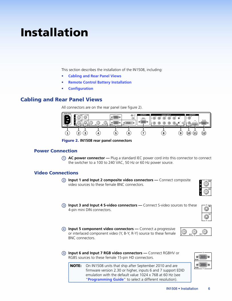
Cabling and Rear Panel ViewsAll connectors are on the rear panel (see figure 2).
50/60Hz
100-240V 50-60Hz
I
N
P
U
T
VID
VID
YC
YC
Y B-Y R-Y RGB DVI
RS-232
1
2 4 5
3
L
1 2 3 4 5 6
7R
AUDIO INPUT
LA
B
R
OUTPUT
L R
OUTPUT
RGBY, B-Y, R-Y
8
7 8
RGB
LISTED1T23I.T.E.
C U S
6
1 6 7 11 122 54 83 9 10
Figure 2. IN1508 rear panel connectors
Power Connection
a AC power connector — Plug a standard IEC power cord into this connector to connect the switcher to a 100 to 240 VAC, 50 Hz or 60 Hz power source.
Video Connections
b Input 1 and Input 2 composite video connectors — Connect composite I
N
P
U
T
VID
VID
1
2
video sources to these female BNC connectors.
c Input 3 and Input 4 S-video connectors — Connect S-video sources to these YC
YC
4
3YC
4-pin mini DIN connectors.
d Input 5 component video connectors — Connect a progressive Y B-Y R-Y
5
or interlaced component video (Y, B-Y, R-Y) source to these female BNC connectors.
e Input 6 and Input 7 RGB video connectors — Connect RGBHV or
RGB7
RGB
6 RGBS sources to these female 15-pin HD connectors.
NOTE: On IN1508 units that ship after September 2010 and are firmware version 2.30 or higher, inputs 6 and 7 support EDID emulation with the default value 1024 x 768 at 60 Hz (see “Programming Guide” to select a different resolution).
IN1508 • Installation 6
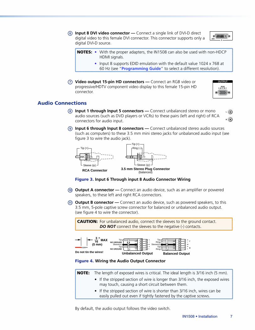
f Input 8 DVI video connector — Connect a single link of DVI-D direct DVI
8
digital video to this female DVI connector. This connector supports only a digital DVI-D source.
NOTES: • With the proper adapters, the IN1508 can also be used with non-HDCP HDMI signals.
• Input 8 supports EDID emulation with the default value 1024 x 768 at 60 Hz (see “Programming Guide” to select a different resolution).
g Video output 15-pin HD connectors — Connect an RGB video or OUTPUT
RGBY, B-Y, R-Y
progressive/HDTV component video display to this female 15-pin HD connector.
Audio Connections
h Input 1 through Input 5 connectors — Connect unbalanced stereo or mono L
R
audio sources (such as DVD players or VCRs) to these pairs (left and right) of RCA connectors for audio input.
i Input 6 through Input 8 connectors — Connect unbalanced stereo audio sources (such as computers) to these 3.5 mm mini stereo jacks for unbalanced audio input (see figure 3 to wire the audio jack).
Tip (+)
Sleeve ( ) Sleeve ( )
Ring (-)
Tip (+)
RCA Connector 3.5 mm Stereo Plug Connector(balanced)
Figure 3. Input 6 Through input 8 Audio Connector Wiring
j Output A connector — Connect an audio device, such as an amplifier or powered speakers, to these left and right RCA connectors.
k Output B connector — Connect an audio device, such as powered speakers, to this 3.5 mm, 5-pole captive screw connector for balanced or unbalanced audio output. (see figure 4 to wire the connector).
CAUTION: For unbalanced audio, connect the sleeves to the ground contact. DO NOT connect the sleeves to the negative (-) contacts.
Do not tin the wires! Balanced Output
LR
RingTip
Sleeve(s)Tip
Ring
Unbalanced Output
Sleeve(s)
Tip
Tip
NO GROUND
NO GROUND
Figure 4. Wiring the Audio Output Connector
NOTE: The length of exposed wires is critical. The ideal length is 3/16 inch (5 mm).
• If the stripped section of wire is longer than 3/16 inch, the exposed wires may touch, causing a short circuit between them.
• If the stripped section of wire is shorter than 3/16 inch, wires can be easily pulled out even if tightly fastened by the captive screws.
By default, the audio output follows the video switch.
IN1508 • Installation 7
RS-232 Connection
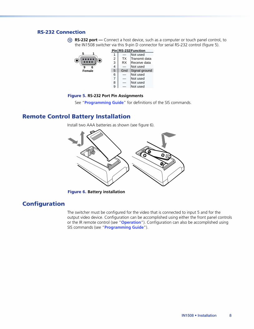
l RS-232 port — Connect a host device, such as a computer or touch panel control, to the IN1508 switcher via this 9-pin D connector for serial RS-232 control (figure 5).
5 1
9 6Female
RS-232 FunctionPin123456789
—TXRX—
Gnd————
Not usedTransmit dataReceive dataNot usedSignal groundNot usedNot usedNot usedNot used
Figure 5. RS-232 Port Pin Assignments
See “Programming Guide” for definitions of the SIS commands.
Remote Control Battery InstallationInstall two AAA batteries as shown (see figure 6).
Figure 6. Battery installation
ConfigurationThe switcher must be configured for the video that is connected to input 5 and for the output video device. Configuration can be accomplished using either the front panel controls or the IR remote control (see “Operation”). Configuration can also be accomplished using SIS commands (see “Programming Guide”).
IN1508 • Installation 8
Operation
This section describes the front panel operation of the IN1508, including:
• Front Panel Controls and Indicators
• Remote Control Buttons
• Operations
• Optimizing the Video
• Optimizing the Audio
• Troubleshooting
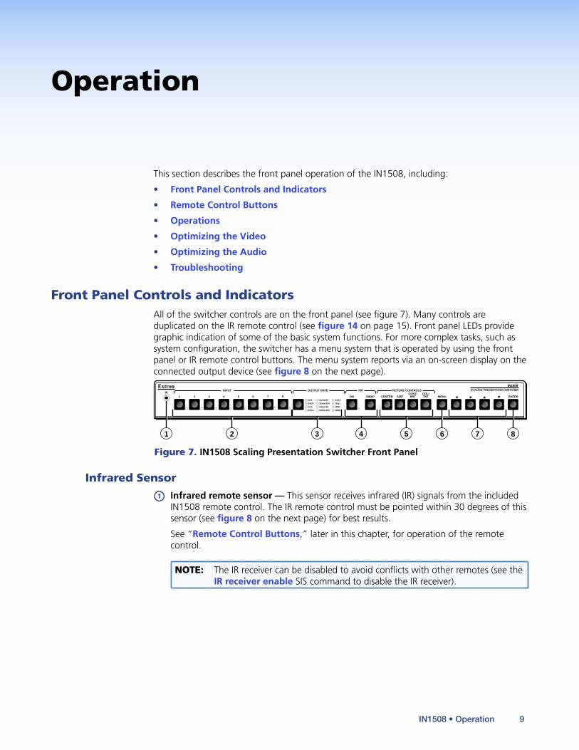
Front Panel Controls and IndicatorsAll of the switcher controls are on the front panel (see figure 7). Many controls are duplicated on the IR remote control (see figure 14 on page 15). Front panel LEDs provide graphic indication of some of the basic system functions. For more complex tasks, such as system configuration, the switcher has a menu system that is operated by using the front panel or IR remote control buttons. The menu system reports via an on-screen display on the connected output device (see figure 8 on the next page).
INPUT OUTPUT RATE PIP SCALING PRESENTATION SWITCHERIR
IN1508PICTURE CONTROLS
VGA
SVGA
XGA
SXGA
ON7654321 SWAP8 CENTER SIZECONT/BRT
COL/TNT MENU ENTER
1024x852
1024x1024
1366x768
1365x1024
UXGA
720p
1080i
1080p
1 6 82 3 4 5 7
Figure 7. IN1508 Scaling Presentation Switcher Front Panel
Infrared Sensor
a Infrared remote sensor — This sensor receives infrared (IR) signals from the included IN1508 remote control. The IR remote control must be pointed within 30 degrees of this sensor (see figure 8 on the next page) for best results.
See “Remote Control Buttons,” later in this chapter, for operation of the remote control.
NOTE: The IR receiver can be disabled to avoid conflicts with other remotes (see the IR receiver enable SIS command to disable the IR receiver).
IN1508 • Operation 9

INPUT
OUTPUT RATE
PIP
DIGITAL VIDEO SCALER
IR
IN1508
PICTURE CONTROL
VGA
SVGA
XGA
SXGA
ON
4
3
2
1
SWAPCENTER
SIZE
CONT/
BRT
COL/
TNT
MENU
ENTER
1024x852
1024x1024
1366x768
1365x1024
UXGA
720p
1080i
1080p
Menu Controls15HD
Menu Controls
PICTURE
OUTPUT
INPUT
ADVANCEDAUDIO Output Volume
Input Gain/Atten
Audio Delay
ASPECT
RATIO
SIZE
ENTER
MENU
CENTER
CONT/
BRT
COL/TINT
VIDEOMUTE
AUDIO
MUTE
A/VMUTE
ZOOM
PAN
5
6
ON/OFFPIP
SWAP
7
8
IN1508
REMOTE
ASPECT
RATIO
SHARP
PHASE
FREEZE
EXTRON ELECTRONICSIN1508 SCALING PRESENTATION SWITCHER
30°
Figure 8. Menu System Display
Input Controls
b Input buttons — The Input 1 through Input 8 buttons (see figure 9) select the associated video input to scale and output. The switch can be a cut or a fade, depending on the switch mode (see “Fade Switch selection box” on page 32). With front panel input selection, audio always follows (switches with) the front panel video selection.
NOTE: Video breakaway switching and audio breakaway switching are available under SIS control (see “Programming Guide”. Audio breakaway switching is not available when the PIP function is on).
INPUT
7654321 8
Figure 9. Input Selection Buttons and LEDs
NOTES: • If the picture-in-picture (PIP) feature is turned on (the PIP On LED, d, is lit), the input buttons select an input for either the primary (main) window or the secondary (PIP) window. If the PIP feature is turned off, the input buttons select the main output only (see “Input Selection Operation” on page 18).
• If the PIP feature is turned on, when an input is selected, the audio associated with that input in the PIP window is muted. The audio does not become unmuted until either:
• It is swapped to the main window.
• A Simple Instruction Set “Audio follow source” command has been issued to configure the switcher to make the audio follow the PIP window.
IN1508 • Operation 10

Auto-Image™ (inputs 6 and 7 only) — Input 6 and input 7 support the Auto-Image function, which automatically sizes and centers the selected input to fill the screen. Press and hold the selected input button for approximately 4 seconds to execute Auto-Image.
NOTE: Auto-Image sets the picture control window center, size, horizontal and vertical start, and horizontal and vertical active pixels controls. It does not affect the total pixels, phase, or aspect ratio controls.
Input LEDs — The Input 1 through Input 8 LEDs indicate the selected video and audio input(s).
An Input LED that is lit green indicates the primary (main) output. If the audio is broken away (switched separately from the video), the Input LED for the selected video light green and the Input LED for the selected audio blinks green.
NOTE: The audio breakaway indication is not available when the switcher is in PIP mode (the PIP On LED, d, is lit).
An Input LED that is lit red indicates the secondary output (the input that is displayed in the PIP window).
NOTE: No input LED lights red if the PIP feature is turned off.
Output Rate Selection
c Output Rate button — The Output Rate button (figure 10) cycles through the available output screen resolutions. Use this button to select the native resolution of the connected video display device. The switcher defaults to a refresh rate of 60 Hz with each resolution selection using the Output Rate button.
NOTE: A number of IN1508 output resolutions are not available from the front panel. These resolutions can be selected using the menu system (see “Resolution selection box” on page 28) and SIS commands (see “Programming Guide” on page 54). The output resolutions not available using the Output Rate button are:
• 852 x 480 • 1400 x 1050 • 1280 x 768 • 1280 x 800 • 1440 x 900 • 1680 x 1050 • 480p • 576p • 1080p Sharp • 1920 x 1200 • 1080p CVT
OUTPUT RATE
VGA
SVGA
XGA
SXGA
1024x852
1024x1024
1366x768
1365x1024
UXGA
720p
1080i
1080p
Pressbutton (P)
P
P
P
P
P
P
P
P
P
P P P
Figure 10. Output Rate Buttons
Output Rate button —The Output Rate LEDs indicate the selected resolution.
IN1508 • Operation 11
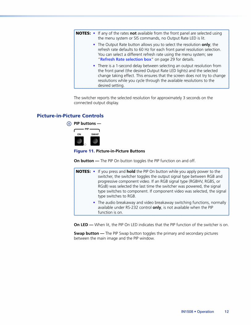
NOTES: • If any of the rates not available from the front panel are selected using the menu system or SIS commands, no Output Rate LED is lit.
• The Output Rate button allows you to select the resolution only; the refresh rate defaults to 60 Hz for each front panel resolution selection. You can select a different refresh rate using the menu system; see “Refresh Rate selection box” on page 29 for details.
• There is a 1-second delay between selecting an output resolution from the front panel (the desired Output Rate LED lights) and the selected change taking effect. This ensures that the screen does not try to change resolutions while you cycle through the available resolutions to the desired setting.
The switcher reports the selected resolution for approximately 3 seconds on the connected output display.
Picture-in-Picture Controls
d PIP buttons —PIP
ON SWAP
Figure 11. Picture-in-Picture Buttons
On button — The PIP On button toggles the PIP function on and off.
NOTES: • If you press and hold the PIP On button while you apply power to the switcher, the switcher toggles the output signal type between RGB and progressive component video. If an RGB signal type (RGBHV, RGBS, or RGsB) was selected the last time the switcher was powered, the signal type switches to component. If component video was selected, the signal type switches to RGB.
• The audio breakaway and video breakaway switching functions, normally available under RS-232 control only, is not available when the PIP function is on.
On LED — When lit, the PIP On LED indicates that the PIP function of the switcher is on.
Swap button — The PIP Swap button toggles the primary and secondary pictures between the main image and the PIP window.
IN1508 • Operation 12
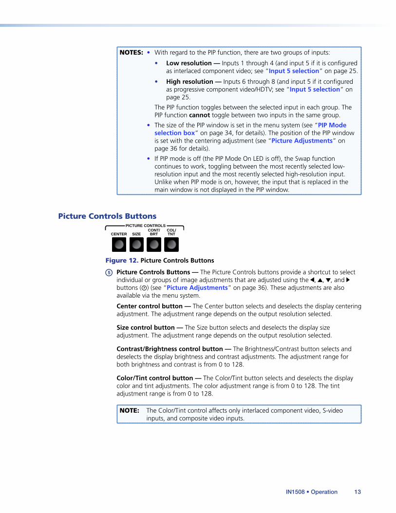
NOTES: • With regard to the PIP function, there are two groups of inputs:
• Low resolution — Inputs 1 through 4 (and input 5 if it is configured as interlaced component video; see “Input 5 selection” on page 25.
• High resolution — Inputs 6 through 8 (and input 5 if it configured as progressive component video/HDTV; see “Input 5 selection” on page 25.
The PIP function toggles between the selected input in each group. The PIP function cannot toggle between two inputs in the same group.
• The size of the PIP window is set in the menu system (see “PIP Mode selection box” on page 34, for details). The position of the PIP window is set with the centering adjustment (see “Picture Adjustments” on page 36 for details).
• If PIP mode is off (the PIP Mode On LED is off), the Swap function continues to work, toggling between the most recently selected low-resolution input and the most recently selected high-resolution input. Unlike when PIP mode is on, however, the input that is replaced in the main window is not displayed in the PIP window.
Picture Controls ButtonsPICTURE CONTROLS
CENTER SIZECONT/BRT
COL/TNT
Figure 12. Picture Controls Buttons
e Picture Controls Buttons — The Picture Controls buttons provide a shortcut to select individual or groups of image adjustments that are adjusted using the , , , and buttons (g) (see “Picture Adjustments” on page 36). These adjustments are also available via the menu system.
Center control button — The Center button selects and deselects the display centering adjustment. The adjustment range depends on the output resolution selected.
Size control button — The Size button selects and deselects the display size adjustment. The adjustment range depends on the output resolution selected.
Contrast/Brightness control button — The Brightness/Contrast button selects and deselects the display brightness and contrast adjustments. The adjustment range for both brightness and contrast is from 0 to 128.
Color/Tint control button — The Color/Tint button selects and deselects the display color and tint adjustments. The color adjustment range is from 0 to 128. The tint adjustment range is from 0 to 128.
NOTE: The Color/Tint control affects only interlaced component video, S-video inputs, and composite video inputs.
IN1508 • Operation 13
Menu Control ButtonsMENU ENTER
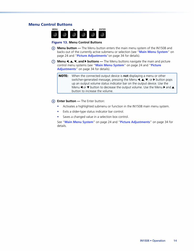
Figure 13. Menu Control Buttons
f Menu button — The Menu button enters the main menu system of the IN1508 and backs out of the currently active submenu or selection (see “Main Menu System” on page 24 and “Picture Adjustments”on page 34 for details).
g Menu , , , and buttons — The Menu buttons navigate the main and picture control menu systems (see “Main Menu System” on page 24 and “Picture Adjustments” on page 34 for details).
NOTE: When the connected output device is not displaying a menu or other switcher-generated message, pressing the Menu , , , or button pops up an output volume status indicator bar on the output device. Use the Menu or button to decrease the output volume. Use the Menu and button to increase the volume.
h Enter button — The Enter button:
• Activates a highlighted submenu or function in the IN1508 main menu system.
• Exits a slider-type status indicator bar control.
• Saves a changed value in a selection box control.
See “Main Menu System” on page 24 and “Picture Adjustments” on page 34 for details.
IN1508 • Operation 14
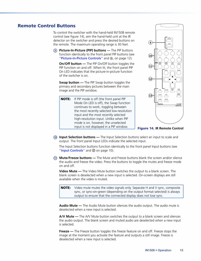
Remote Control ButtonsTo control the switcher with the hand-held IN1508 remote control (see figure 14), aim the hand-held unit at the IR detector on the switcher and press the desired buttons on the remote. The maximum operating range is 30 feet.
i Picture-In-Picture (PIP) buttons — The PIP buttons function identically to the front panel PIP buttons (see “Picture-in-Picture Controls” and d, on page 12).
On/Off button — The PIP On/Off button toggles the PIP function on and off. When lit, the front panel PIP On LED indicates that the picture-in-picture function of the switcher is on.
Swap button — The PIP Swap button toggles the primary and secondary pictures between the main image and the PIP window.
NOTE: If PIP mode is off (the front panel PIP Mode On LED is off), the Swap function continues to work, toggling between the most recently selected low-resolution input and the most recently selected high-resolution input. Unlike when PIP mode is on, however, the unselected input is not displayed in a PIP window.
j Input Selection buttons — The Input Selection buttons select an input to scale and output. The front panel Input LEDs indicate the selected input.
The Input Selection buttons function identically to the front panel Input buttons (see “Input Controls” and b on page 10).
k Mute/Freeze buttons — The Mute and Freeze buttons blank the screen and/or silence the audio and freeze the video. Press the buttons to toggle the mutes and freeze mode on and off.
Video Mute — The Video Mute button switches the output to a blank screen. The blank screen is deselected when a new input is selected. On-screen displays are still available when the video is muted.
NOTE: Video mute mutes the video signals only. Separate H and V sync, composite sync, or sync-on-green (depending on the output format selected) is always output to ensure that the connected display does not lose sync.
Audio Mute — The Audio Mute button silences the audio output. The audio mute is deselected when a new input is selected.
A/V Mute — The A/V Mute button switches the output to a blank screen and silences the audio output. The blank screen and muted audio are deselected when a new input is selected.
Freeze — The Freeze button toggles the freeze feature on and off. Freeze stops the image at the moment you activate the feature and outputs a still image. Freeze is deselected when a new input is selected.
SIZE
ENTERMENU
CENTERCONT/
BRTCOL/TINT
VIDEOMUTE
AUDIOMUTE
A/VMUTE
5 6
ON/OFFPIP
SWAP
7 8
IN1508REMOTE
ZOOM PAN
SHARP PHASE
ASPECTRATIO
FREEZE
12
13
10
9
11
Figure 14. IR Remote Control
IN1508 • Operation 15
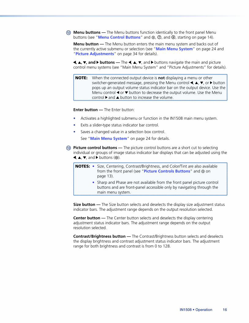
l Menu buttons — The Menu buttons function identically to the front panel Menu buttons (see “Menu Control Buttons” and f, g, and h, starting on page 14).
Menu button — The Menu button enters the main menu system and backs out of the currently active submenu or selection (see “Main Menu System” on page 24 and “Picture Adjustments” on page 34 for details).
, , , and buttons — The , , , and buttons navigate the main and picture control menu systems (see “Main Menu System” and “Picture Adjustments” for details).
NOTE: When the connected output device is not displaying a menu or other switcher-generated message, pressing the Menu control , , , or button pops up an output volume status indicator bar on the output device. Use the Menu control or button to decrease the output volume. Use the Menu control and button to increase the volume.
Enter button — The Enter button:
• Activates a highlighted submenu or function in the IN1508 main menu system.
• Exits a slider-type status indicator bar control.
• Saves a changed value in a selection box control.
See “Main Menu System” on page 24 for details.
m Picture control buttons — The picture control buttons are a short cut to selecting individual or groups of image status indicator bar displays that can be adjusted using the
, , , and buttons (l).
NOTES: • Size, Centering, Contrast/Brightness, and Color/Tint are also available from the front panel (see “Picture Controls Buttons” and e on page 13).
• Sharp and Phase are not available from the front panel picture control buttons and are front-panel accessible only by navigating through the main menu system.
Size button — The Size button selects and deselects the display size adjustment status indicator bars. The adjustment range depends on the output resolution selected.
Center button — The Center button selects and deselects the display centering adjustment status indicator bars. The adjustment range depends on the output resolution selected.
Contrast/Brightness button — The Contrast/Brightness button selects and deselects the display brightness and contrast adjustment status indicator bars. The adjustment range for both brightness and contrast is from 0 to 128.
IN1508 • Operation 16
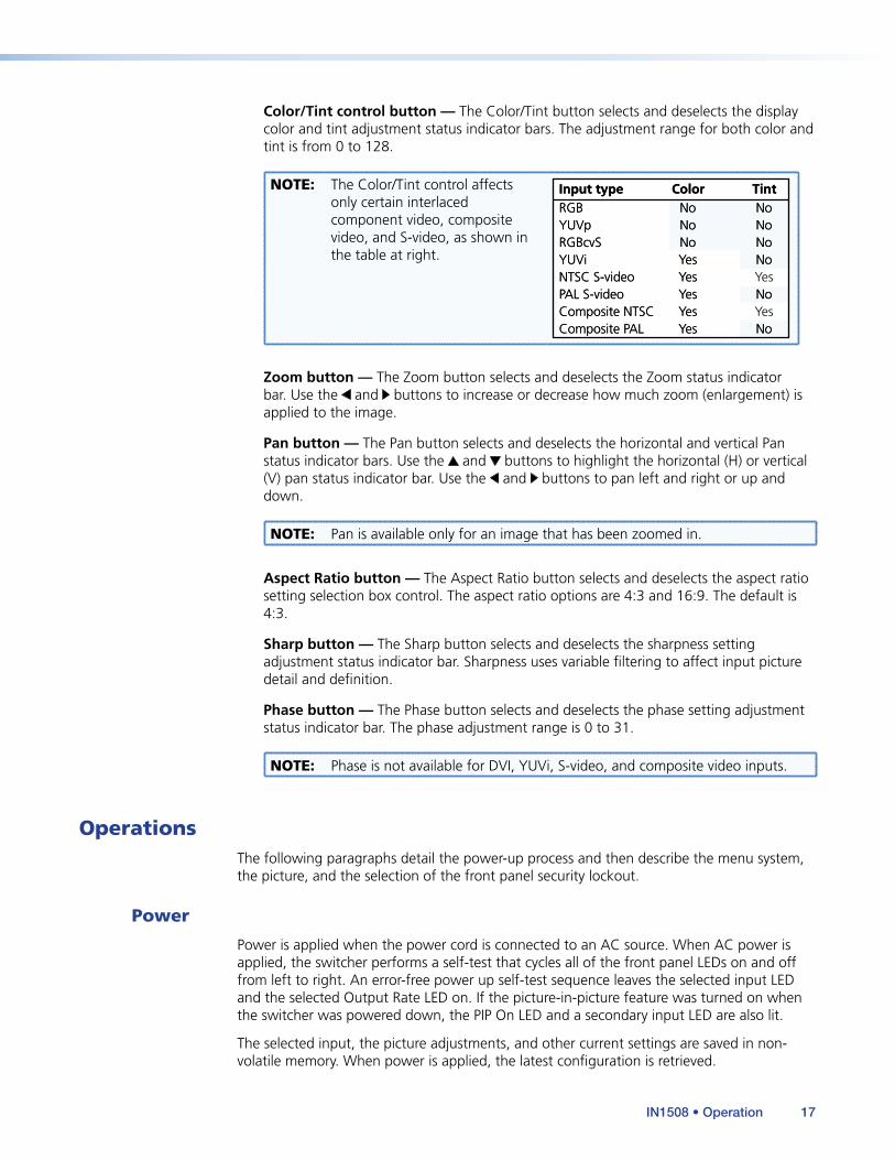
Color/Tint control button — The Color/Tint button selects and deselects the display color and tint adjustment status indicator bars. The adjustment range for both color and tint is from 0 to 128.
NOTE: The Color/Tint control affects only certain interlaced component video, composite video, and S-video, as shown in the table at right.
Input type Color TintRGB No NoYUVp No NoRGBcvS No NoYUVi Yes NoNTSC S-video Yes YesPAL S-video Yes NoComposite NTSC Yes YesComposite PAL Yes No
Input type Color TintRGB No NoYUVp No NoRGBcvS No NoYUVi Yes NoNTSC S-video Yes YesPAL S-video Yes NoComposite NTSC Yes YesComposite PAL Yes No
Zoom button — The Zoom button selects and deselects the Zoom status indicator bar. Use the and buttons to increase or decrease how much zoom (enlargement) is applied to the image.
Pan button — The Pan button selects and deselects the horizontal and vertical Pan status indicator bars. Use the and buttons to highlight the horizontal (H) or vertical (V) pan status indicator bar. Use the and buttons to pan left and right or up and down.
NOTE: Pan is available only for an image that has been zoomed in.
Aspect Ratio button — The Aspect Ratio button selects and deselects the aspect ratio setting selection box control. The aspect ratio options are 4:3 and 16:9. The default is 4:3.
Sharp button — The Sharp button selects and deselects the sharpness setting adjustment status indicator bar. Sharpness uses variable filtering to affect input picture detail and definition.
Phase button — The Phase button selects and deselects the phase setting adjustment status indicator bar. The phase adjustment range is 0 to 31.
NOTE: Phase is not available for DVI, YUVi, S-video, and composite video inputs.
OperationsThe following paragraphs detail the power-up process and then describe the menu system, the picture, and the selection of the front panel security lockout.
Power
Power is applied when the power cord is connected to an AC source. When AC power is applied, the switcher performs a self-test that cycles all of the front panel LEDs on and off from left to right. An error-free power up self-test sequence leaves the selected input LED and the selected Output Rate LED on. If the picture-in-picture feature was turned on when the switcher was powered down, the PIP On LED and a secondary input LED are also lit.
The selected input, the picture adjustments, and other current settings are saved in non-volatile memory. When power is applied, the latest configuration is retrieved.
IN1508 • Operation 17
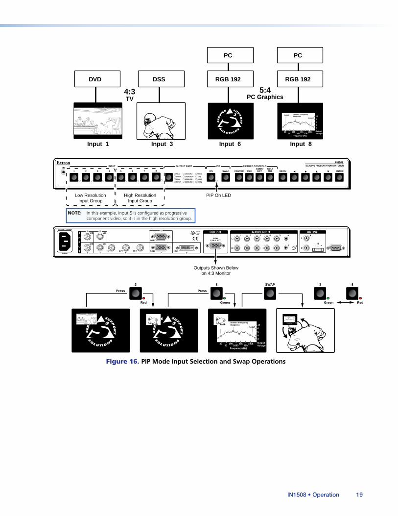
Input Selection Operation
Each of the inputs is assigned to one of two groups (see figure 16 on the next page):
• Low resolution — Inputs 1 through 4 (and input 5 if it is configured as interlaced component video (see “Input 5 selection” on page 25).
• High resolution — Inputs 6 through 8 (and input 5 if it configured as progressive component video/HDTV (see “Input 5 selection” on page 25).
Input selection acts differently, depending on whether PIP mode is on or off:
• PIP mode on — If PIP mode is on (the PIP On LED is lit), pressing the input button selects a new input for display in either the main window or the PIP window. The window in which the selected input is displayed depends on which group (high resolution or low resolution) the input is in. The selected input replaces the previously selected input from the same group in whichever window that input had been displayed.
• In figure 16, when you press the Input 3 button, input 3 replaces input 1 in the PIP window.
• In figure 16, when you press the Input 8 button, input 8 replaces input 6 in the main window.
• PIP mode off — If the PIP mode is off (the PIP On LED is off), pressing the input button selects a new input for display in the main window.
Picture-in-picture Mode Operation
The two images displayed when the PIP feature is on (the PIP On LED is lit) must come from different input groups (one high resolution and one low resolution).
• If the primary input (the image displayed in the main window) is a high-resolution input, the secondary input (the image displayed in the PIP window) must be a low-resolution input (see figure 16).
• If the primary input is a low-resolution input, the secondary input must be a high-resolution input (see figure 16).
The PIP function toggles between the selected input in each group. In figure 16, when you press the Swap button:
• Input 3 replaces input 8 in the main window.
• Input 8 replaces input 3 in the PIP window.
The PIP feature cannot toggle between two inputs in the same group.
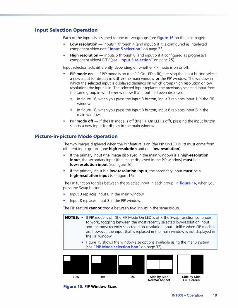
NOTES: • If PIP mode is off (the PIP Mode On LED is off), the Swap function continues to work, toggling between the most recently selected low-resolution input and the most recently selected high-resolution input. Unlike when PIP mode is on, however, the input that is replaced in the main window is not displayed in the PIP window.
• Figure 15 shows the window size options available using the menu system (see “PIP Mode selection box” on page 32).
1/25 1/9 1/4 Side by SideNormal Aspect
Side by SideFull Screen
Figure 15. PIP Window Sizes
IN1508 • Operation 18
INPUT OUTPUT RATE PIP IR
PICTURE CONTROLS
VGA
SVGA
XGA
SXGA
ON 7 6 5 4 3 2 1 SWAP
SWAP
8 CENTER SIZE CONT/ BRT
COL/ TNT MENU ENTER
1024x852
1024x1024
1366x768
1365x1024
UXGA
720p
1080i
1080p
3
Red
Press
8
Green
3
Green
Press
Red
8
50/60Hz
100-240V 50-60Hz
I
N
P
U
T
VID
VID
YC
YC
Y B-Y R-Y RGB DVI
1
2 4 5
3
L
1 2 3 4 5 6
7R
AUDIO INPUT
LA
B
R
OUTPUT
L R
OUTPUT
RGBY, B-Y, R-Y
8
7 8
RGB
6 LISTED1T23I.T.E.
C U S
DSS DVD
TV 4:3
PC Graphics 5:4
Input 1 Input 3 Input 6 Input 8
Low Resolution Input Group
High Resolution Input Group
PIP On LED
Outputs Shown Belowon 4:3 Monitor
RGB 192
PC
RGB 192
PC
2
4
6
8
10
20 50
100 1000
10k 75k
100k Output Voltage
Frequency (Hz)
Rolloff Uneven Frequency Response
Rolloff
2
4
6
8
10
2050
1001000
10k75k
100k OutputVoltage
Frequency (Hz)
Rolloff Uneven FrequencyResponse
Rolloff
2
4
6
8
10
2050
1001000
10k75k
100k OutputVoltage
Frequency (Hz)
Rolloff Uneven FrequencyResponse
Rolloff
SCALING PRESENTATION SWITCHER
IN1508
NOTE: In this example, input 5 is configured as progressive component video, so it is in the high resolution group.
Figure 16. PIP Mode Input Selection and Swap Operations
IN1508 • Operation 19
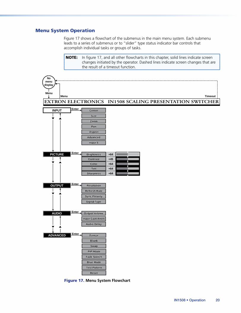
Menu System Operation
Figure 17 shows a flowchart of the submenus in the main menu system. Each submenu leads to a series of submenus or to “slider” type status indicator bar controls that accomplish individual tasks or groups of tasks.
NOTE: In figure 17, and all other flowcharts in this chapter, solid lines indicate screen changes initiated by the operator. Dashed lines indicate screen changes that are the result of a timeout function.
Size Size
Center Center
Aspect Aspect
Zoom Zoom
Pan Pan
Freeze Freeze
Blank Blank
PIP Mode PIP Mode
Swap Swap
Fade Switch Fade Switch
Test PatternTest Pattern
Blue ModeBlue Mode
ResetReset
Menu
Enter
Enter
No menu
display
Menu Timeout
EXTRON ELECTRONICS IN1508 SCALING PRESENTATION SWITCHER
INPUT
ADVANCED
Advanced Advanced
Input 5 Input 5
Enter PICTURE +45
+64
+64
+64
Sharpness Sharpness
Color Color
Tint Tint
Brightness Brightness
Contrast Contrast
+64
Resolution Resolution
Refresh Rate Refresh Rate
Sync Polarity Sync Polarity
Signal Type Signal Type
Enter OUTPUT
Enter AUDIO
Input Gain/AttenInput Gain/Atten
Output Volume Output Volume
Audio Delay Audio Delay
Figure 17. Menu System Flowchart
IN1508 • Operation 20
Menu button — Press the front panel or IR remote control Menu button to activate the menu system or to back up one level from the currently selected submenu or selection. (For example, pressing the Menu button in the Picture submenu turns off the Picture submenu selections and the switcher displays the main menu only).
, , , and buttons — Press the front panel or IR remote control , , , and buttons to navigate through the menu system, highlighting submenus or selections or increasing and decreasing selected picture control settings.
Enter button — Press the front panel or IR remote control Enter button to:
• Activate a highlighted submenu or function in the IN1508 main menu system
• Exit a slider-type status indicator bar control
• Save a changed value in a selection box control
NOTE: To return to normal operation (no menus), let the switcher remain idle for 20 seconds until the selected screen times out, or press the front panel or IR remote control Menu button repeatedly until the Main Menu is deselected.
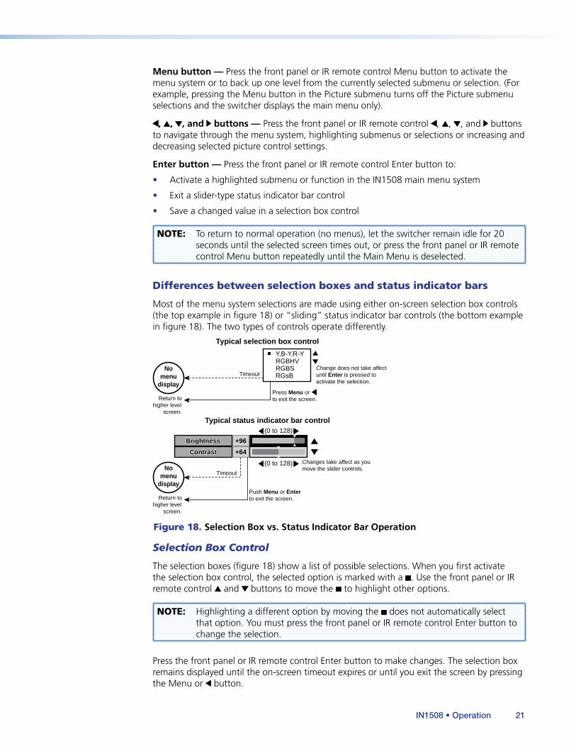
Differences between selection boxes and status indicator bars
Most of the menu system selections are made using either on-screen selection box controls (the top example in figure 18) or “sliding” status indicator bar controls (the bottom example in figure 18). The two types of controls operate differently.
Press Menu orto exit the screen.
ContrastContrast
BrightnessBrightness +96
+64
(0 to 128)
(0 to 128)Timeout
Changes take affect as youmove the slider controls.
Typical status indicator bar control
Typical selection box control
Change does not take affectuntil Enter is pressed toactivate the selection.
Return tohigher level
screen.
Timeout
RGBHV
RGsB
Y,B-Y,R-Y
RGBS
Push Menu or Enterto exit the screen.
Nomenu
display
Return tohigher level
screen.
Nomenu
display
Figure 18. Selection Box vs. Status Indicator Bar Operation
Selection Box Control
The selection boxes (figure 18) show a list of possible selections. When you first activate the selection box control, the selected option is marked with a . Use the front panel or IR remote control and buttons to move the to highlight other options.
NOTE: Highlighting a different option by moving the does not automatically select that option. You must press the front panel or IR remote control Enter button to change the selection.
Press the front panel or IR remote control Enter button to make changes. The selection box remains displayed until the on-screen timeout expires or until you exit the screen by pressing the Menu or button.
IN1508 • Operation 21
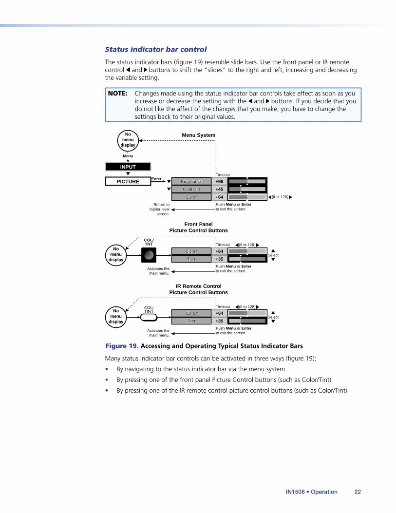
Status indicator bar control
The status indicator bars (figure 19) resemble slide bars. Use the front panel or IR remote control and buttons to shift the “slides” to the right and left, increasing and decreasing the variable setting.
NOTE: Changes made using the status indicator bar controls take effect as soon as you increase or decrease the setting with the and buttons. If you decide that you do not like the affect of the changes that you make, you have to change the settings back to their original values.
ColorColor
TintTint +35
+64
Enter
COL/TNT
Front PanelPicture Control Buttons
Menu System
(0 to 128)
(0 to 128)
PICTURE
+64ColorColor
+45
+96BrightnessBrightness
ContrastContrast
Select
Nomenu
display
INPUT
Menu
Nomenu
display
ColorColor
TintTint +35
+64
IR Remote ControlPicture Control Buttons
(0 to 128)
Select
Nomenu
display
COL/TINT
Timeout
Timeout
Timeout
Return tohigher level
screen.
Push Menu or Enterto exit the screen.
Activates themain menu.
Activates themain menu.
Push Menu or Enterto exit the screen.
Push Menu or Enterto exit the screen.
Figure 19. Accessing and Operating Typical Status Indicator Bars
Many status indicator bar controls can be activated in three ways (figure 19):
• By navigating to the status indicator bar via the menu system
• By pressing one of the front panel Picture Control buttons (such as Color/Tint)
• By pressing one of the IR remote control picture control buttons (such as Color/Tint)
IN1508 • Operation 22
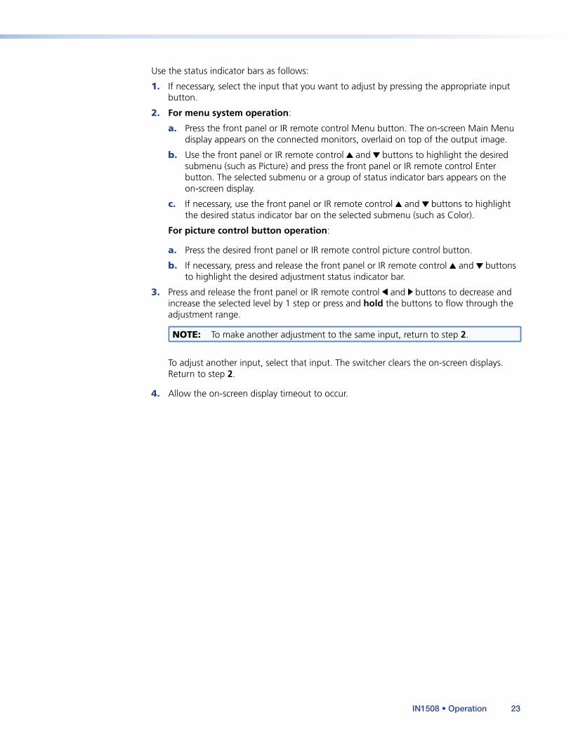
Use the status indicator bars as follows:
1. If necessary, select the input that you want to adjust by pressing the appropriate input button.
2. For menu system operation:
a. Press the front panel or IR remote control Menu button. The on-screen Main Menu display appears on the connected monitors, overlaid on top of the output image.
b. Use the front panel or IR remote control and buttons to highlight the desired submenu (such as Picture) and press the front panel or IR remote control Enter button. The selected submenu or a group of status indicator bars appears on the on-screen display.
c. If necessary, use the front panel or IR remote control and buttons to highlight the desired status indicator bar on the selected submenu (such as Color).
For picture control button operation:
a. Press the desired front panel or IR remote control picture control button.
b. If necessary, press and release the front panel or IR remote control and buttons to highlight the desired adjustment status indicator bar.
3. Press and release the front panel or IR remote control and buttons to decrease and increase the selected level by 1 step or press and hold the buttons to flow through the adjustment range.
NOTE: To make another adjustment to the same input, return to step 2.
To adjust another input, select that input. The switcher clears the on-screen displays. Return to step 2.
4. Allow the on-screen display timeout to occur.
IN1508 • Operation 23

Main Menu System
The main menu includes the following submenus:
• Input submenu — Size, centering, and aspect ratio• Picture submenu — Image quality adjustments• Output submenu — Resolution, refresh rate, sync, and signal format• Audio submenu — Input audio volume and audio delay• Advanced submenu — Advanced options
Input submenu
Figure 20 shows an overview of the Input submenu, its available selections, and their available settings. Use the front panel or IR remote control and buttons to highlight the desired selection and press the Enter button.
Timeout
Timeout
Timeout
Timeout
Timeout
Timeout
Timeout
Timeout
Timeout
Timeout
Timeout
No menu
display
AUDIO
PICTURE
INPUT
OUTPUT
ADVANCED
Menu Menu
Timeout
Timeout
Timeout
Timeout
Menu
Menu Menu
Menu
Menu
Enter
Enter
Enter
Menu
Menu
Menu
Menu
Menu
Menu
H
Menu
H
Menu
V
Timeout
Timeout V
Size
Pan
Aspect
Advanced
Input 5
Enter
Timeout
Timeout
Menu Enter
Menu
Center
Zoom Enter
Enter
Menu
16:9 4:3
Menu
HDTVProgressiveInterlaced
Enter Select
+480
+640
0
+8
V-Start
Phase
H-Start
Active Pixels
Active Lines
+127
Press Enter to select a change.
Ranges for Advance selections varies based on input applied and output rate selected. Press Enter to
select a change.
Total Pixels +800
H
Menu Z
V Size
Pan
Aspect
Advanced
Input 5
Center
Zoom
V-Start
Phase
H-Start
Active Pixels
Active Lines
Total Pixels
Figure 20. Input Submenu Flowchart
Center selection
The Center selection displays two status indicator bars that show, and allow you to adjust, the horizontal and vertical position of the main or picture-in-picture output on the monitor.
If the PIP feature is turned off (the front panel PIP On LED is unlit), Center adjusts the position of the main window.
If the picture-in-picture feature is turned on (the front panel PIP On LED is lit), Center adjusts the position of the PIP window.
The center adjustments do not crop the image or add blank lines.
Use the front panel or IR remote control and buttons to highlight the horizontal (H) or vertical (V) centering status indicator bar. Use the front panel or IR remote control and buttons to move the image.
IN1508 • Operation 24
Size selection
The Size selection displays two status indicator bars that show, and allow you to adjust, the horizontal and vertical size of the output. Use the front panel or IR remote control and buttons to highlight the horizontal (H) or vertical (V) size status indicator bar. Use the front panel or IR remote control and buttons to increase or decrease the size.
Zoom selection
The Zoom selection displays a status indicator bar that allows you to adjust the zoom level of the output. Use the front panel or IR remote control and buttons to increase or decrease how much zoom (enlargement) is applied to the image.
Pan selection
The Pan selection displays two status indicator bars that allow you to pan (move) horizontally and vertically on a zoomed image. Use the front panel or IR remote control and buttons to highlight the horizontal (H) or vertical (V) pan status indicator bar. Use the front panel or IR remote control and buttons to pan left and right or up and down.
Aspect ratio selection
The Aspect ratio selection displays a selection box that shows the currently selected aspect ratio and allows you to select another aspect ratio.
Use the front panel or IR remote control and buttons to highlight the desired aspect ratio. Press the Enter button to change to the highlighted value. The default for each input is 4:3.
NOTE: All signals applied to an input, such as input 6, share the common aspect ratio setting for that input. Each IN1508 input has a unique aspect ratio setting.
Advanced screen
NOTE: The Advanced settings available from the Input submenu are a comprehensive set of adjustments to optimize the switcher for non-standard video inputs. Most users do not encounter such signals. For those users who do, the switcher automatically adjusts these settings. The automatic adjustments of the switcher are adequate for most inputs.
The Advanced screen provides a submenu of advanced selection options: active pixels, active lines, phase, horizontal and vertical start, and total pixels. These advanced settings are rarely needed for standard video and computer video signals, but provide the user with manual control over scaling parameters that are automatic. The knowledgeable user may need to adjust these settings to optimize his or her input signal(s). Possible reasons to adjust these settings include tolerance issues and nonstandard resolutions and frequencies. The settings are described in more detail as part of the discussion on optimizing the video (see “Input Submenu > Advanced Selections”, on page 40).
To select one of the advanced settings, use the front panel or IR remote control or button to highlight the desired status indicator bar.
Input 5 selection
The Input 5 selection displays a selection box that shows the currently assigned component video format (interlaced [NTSC/PAL/SECAM], progressive [480p/576p], or HDTV [720p/1080i/1080p]) for input 5 and allows you to select a different format.
IN1508 • Operation 25
Use the front panel or IR remote control and buttons to highlight the desired component video format. Press the Enter button to change to the highlighted value. The default is progressive.
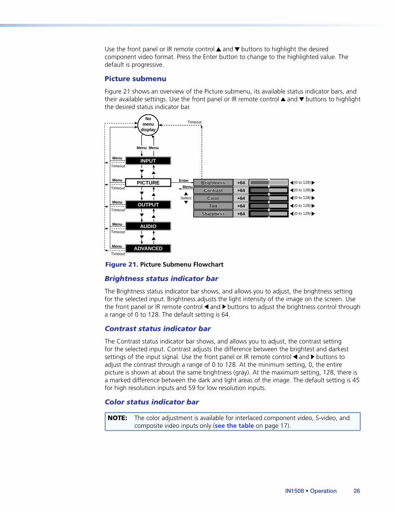
Picture submenu
Figure 21 shows an overview of the Picture submenu, its available status indicator bars, and their available settings. Use the front panel or IR remote control and buttons to highlight the desired status indicator bar.
Timeout
Timeout
Timeout
Timeout
Menu
Timeout
Menu
Menu
Menu
Menu
TimeoutNo
menudisplay
AUDIO
PICTURE
INPUT
OUTPUT
ADVANCED
MenuMenu
Select
(0 to 128)
(0 to 128)
(0 to 128)
(0 to 128)
(0 to 128)
+64
+64
+64
+64
Sharpness
Color
Tint
Brightness
Contrast
Sharpness
Color
Tint
Brightness
Contrast
+64
Menu
Enter
Figure 21. Picture Submenu Flowchart
Brightness status indicator bar
The Brightness status indicator bar shows, and allows you to adjust, the brightness setting for the selected input. Brightness adjusts the light intensity of the image on the screen. Use the front panel or IR remote control and buttons to adjust the brightness control through a range of 0 to 128. The default setting is 64.
Contrast status indicator bar
The Contrast status indicator bar shows, and allows you to adjust, the contrast setting for the selected input. Contrast adjusts the difference between the brightest and darkest settings of the input signal. Use the front panel or IR remote control and buttons to adjust the contrast through a range of 0 to 128. At the minimum setting, 0, the entire picture is shown at about the same brightness (gray). At the maximum setting, 128, there is a marked difference between the dark and light areas of the image. The default setting is 45 for high resolution inputs and 59 for low resolution inputs.
Color status indicator bar
NOTE: The color adjustment is available for interlaced component video, S-video, and composite video inputs only (see the table on page 17).
IN1508 • Operation 26
The Color status indicator bar shows, and allows you to adjust, the color setting for the selected input. Color increases and decreases the color intensity of the picture. Use the front panel or IR remote control and buttons to adjust the contrast through a range of 0 to 128. At the minimum setting, 128, the switcher removes most of the color. The default setting is 64.
Tint status indicator bar
NOTE: The tint adjustment is available for S-video and composite video inputs only (see the table on page 17).
The tint status indicator bar shows, and allows you to adjust, the tint setting. Tint is a relative measure of the amount of white in a given color and adjusts the color of the picture toward red or green. Use the front panel or IR remote control and buttons to adjust the tint control through a range of 0 to 128. Press the button to increase the green (and decrease the red). Press the button to increase the red (and decrease the green). The default setting is 64.
Sharpness status indicator bar
The Sharpness status indicator bar shows and allows you to adjust the sharpness setting. Sharpness uses variable filtering to affect input picture detail and definition. Use the front panel or IR remote control and buttons to increase or decrease the sharpness filtering through a range of 0 to 128. The default setting is 64.
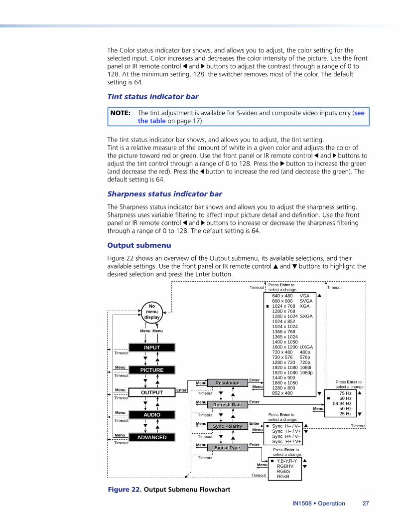
Output submenu
Figure 22 shows an overview of the Output submenu, its available selections, and their available settings. Use the front panel or IR remote control and buttons to highlight the desired selection and press the Enter button.
Timeout
Timeout
Timeout
Timeout
Timeout
Timeout
Timeout
Nomenu
display
AUDIO
PICTURE
INPUT
OUTPUT
ADVANCED
MenuMenu
Timeout
Timeout
Timeout
Timeout
Menu
Menu
Menu
Menu
Menu
Enter
Enter
Enter Menu
Menu
Menu
Enter
Enter
Timeout Timeout
1024 x 8521024 x 10241366 x 7681365 x 1024
800 x 600640 x 480
1024 x 768
1280 x 1024
720 x 480720 x 576
1600 x 12001400 x 1050
1280 x 7201920 x 10801920 x 1080
SVGAVGA
XGA1280 x 768
SXGA
480p576p
UXGA
720p1080i1080p
1440 x 9001680 x 10501280 x 800852 x 480
25 Hz50 Hz
60 Hz59.94 Hz
75 Hz
Sync H– / V+ Sync H– / V–
Sync H+ / V+ Sync H+ / V–
Resolution Resolution
Refresh Rate Refresh Rate
Sync Polarity Sync Polarity
Signal Type Signal Type
Menu
Menu
Menu
Menu
Press Enter toselect a change.
Press Enter to select a change.
Press Enter to select a change.
Press Enter toselect a change.
RGBHV
RGsB
Y,B-Y,R-Y
RGBS
Figure 22. Output Submenu Flowchart
IN1508 • Operation 27

NOTE: Resolution and refresh rate are crucial variables for optimum image quality. For best results, set the switcher output to match the native resolution of your display (see “Optimizing the Video” on page 38 for detailed guidelines for choosing the proper resolution and rate).
Resolution selection box
NOTES: • Three additional rates, 1080p Sharp, 1920 x 1200, and 1080p CVT are available, but cannot be selected either using the Ouptut Rate button or via the Resolution selection box. These rates can only be selected under RS-232 control (see “Programming Guide” on page 54).
• The front panel Output Rate button can also be used to select most of the resolutions that are available in this box, with the following exceptions:
• 852 x 480 • 1400 x 1050 • 1280 x 768 • 1280 x 800 • 1440 x 900 • 1680 x 1050 • 480p • 576p.
The Resolution selection box identifies the currently selected output resolution and allows you to select a different output resolution. The table below defines the combinations of resolutions and refresh rates that are available using the menu controls.
The default resolution is XGA. To select a different resolution, use the front panel or IR remote control or button to highlight the desired resolution and press the Enter button.
Resolution Aspectratio 50 Hz 60 Hz 75 Hz
640 x 480 VGA 4:3
800 x 600 SVGA 4:3
1024 x 768 XGA 4:3
1280 x 1024 SXGA 4:3
1024 x 852 4:3
1024 x 1024 4:3
1366 x 768 16:9
1365 x 1024 4:3
1400 x 1050 4:3
1280 x 720 720p 16:9
1920 x 1080 1080i 16:9
1920 x 1080 1080p 16:9
�
�
�
�
�
�
�
�
�
�
�
�
1280 x 768 16:9 �
�
�
�
�
�
�
�
�
�
�
�
�
�
�
�
�
720 x 576 576p 4:3 �
720 x 480 480p 4:3 �
�
�
�
�
24 Hz
�
�
��� �
1680 x 1050 16:9
1280 x 800 16:9
1080p CVT 16:9
�
�1440 x 900 16:9 �
��
�
1920 x 1200 16:9 �
1080p Sharp 16:9 �
852 x 480 16:9 � �
59.94 Hz
�
1600 x 1200 UXGA 4:3
NOTES: • 1080p Sharp is an HDTV 1080p rate specifically tailored to Sharp® Professional displays (such as the G655u).
• 1080p CVT is an HDTV 1080p rate specifically tailored to CVT (Coordinated Video Timings) reduced blanking timings.
IN1508 • Operation 28
Refresh Rate selection box
NOTE: The front panel Output Rate button can be used to select the resolution, but every front panel rate selection defaults to 60 Hz. Different refresh rates can be selected only by using this screen or RS-232 control.
The Refresh Rate selection box identifies the currently selected output refresh rate and allows you to select a different rate.
To select a different rate, use the front panel or IR remote control or button to highlight the desired resolution and press the Enter button.
Sync Polarity selection box
The Sync Polarity selection box identifies the currently selected sync polarity and provides the ability to select different sync polarities. The display or projector may require video with positive or negative horizontal (H) and/or vertical (V) sync polarity; consult the diplay or projector manual.
To select a different sync polarity, use the front panel or IR remote control or button to highlight the desired sync format and press the Enter button. The default setting is H–/V–.
Signal Type selection box
The Signal Type selection box identifies the currently selected output signal format (RGBHV, RGBS, RGsB, or progressive component video [Y, B-Y, R-Y]) and provides the ability to select a different type. To select a different sync type, use the front panel or IR remote control or
button to highlight the desired sync type and press the enter button. The default setting is RGBHV.
NOTE: Another way to select the output signal type is to press and hold the PIP On button while you apply power to the switcher. This action toggles the signal type between RGBHV and progressive component video. If RGB was selected the last time the switcher was powered, the signal type switches to component video. If component video was selected, the signal type switches to RGB.
IN1508 • Operation 29
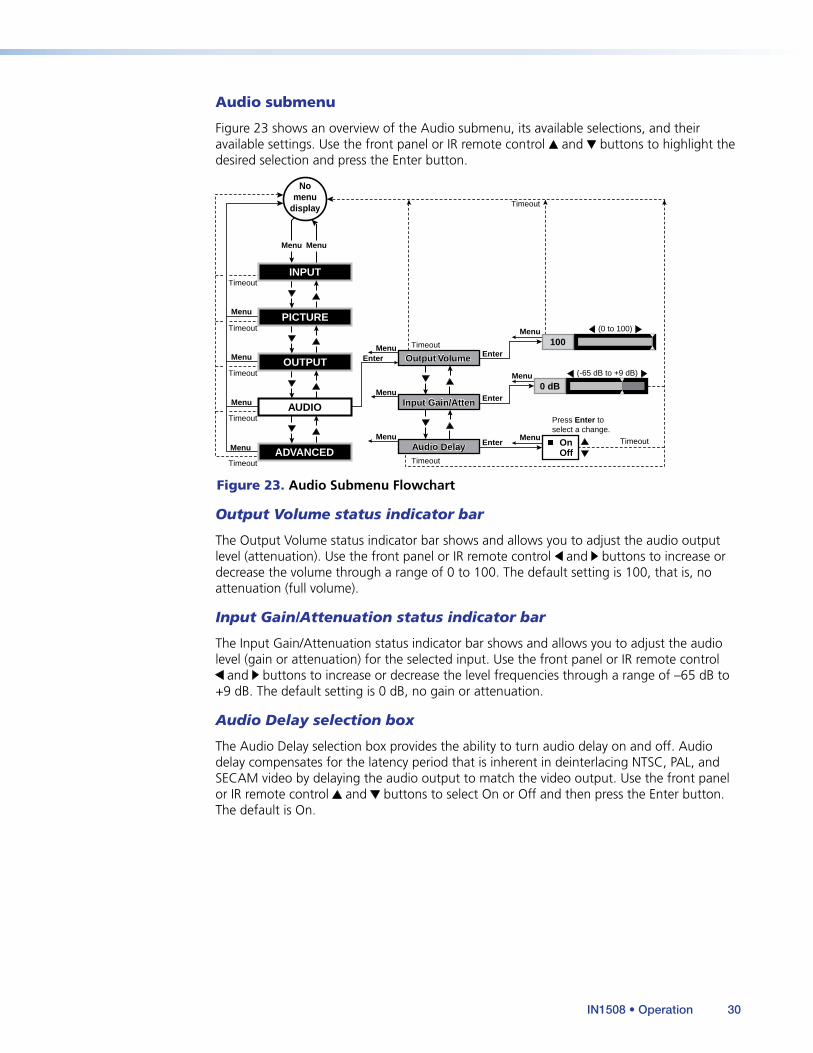
Audio submenu
Figure 23 shows an overview of the Audio submenu, its available selections, and their available settings. Use the front panel or IR remote control and buttons to highlight the desired selection and press the Enter button.
Menu
Menu
Menu
Menu
Timeout
Enter
Menu
No menu
display
0 dB
Timeout
Timeout
Timeout Enter
Press Enter to select a change.
Menu
(-65 dB to +9 dB)
Menu
Menu
Off On
AUDIO Input Gain/AttenInput Gain/Atten
Enter
Menu 100
(0 to 100)
Menu Enter Output Volume Output Volume
Audio Delay Audio Delay
PICTURE
INPUT
OUTPUT
ADVANCED
Menu Menu
Timeout
Timeout
Timeout
Timeout
Timeout
Figure 23. Audio Submenu Flowchart
Output Volume status indicator bar
The Output Volume status indicator bar shows and allows you to adjust the audio output level (attenuation). Use the front panel or IR remote control and buttons to increase or decrease the volume through a range of 0 to 100. The default setting is 100, that is, no attenuation (full volume).
Input Gain/Attenuation status indicator bar
The Input Gain/Attenuation status indicator bar shows and allows you to adjust the audio level (gain or attenuation) for the selected input. Use the front panel or IR remote control
and buttons to increase or decrease the level frequencies through a range of –65 dB to +9 dB. The default setting is 0 dB, no gain or attenuation.
Audio Delay selection box
The Audio Delay selection box provides the ability to turn audio delay on and off. Audio delay compensates for the latency period that is inherent in deinterlacing NTSC, PAL, and SECAM video by delaying the audio output to match the video output. Use the front panel or IR remote control and buttons to select On or Off and then press the Enter button. The default is On.
IN1508 • Operation 30

Advanced submenu
Figure 24 shows an overview of the Advanced submenu, its available selections, and their available settings.
Timeout
Timeout
Timeout
Timeout
Timeout
Timeout
Timeout
Timeout
Timeout
Timeout
Timeout
Timeout
Nomenu
display
AUDIO
PICTURE
INPUT
OUTPUT
ADVANCED
MenuMenu
Timeout
Timeout
Timeout
Timeout
Menu
Menu
Menu
Menu
Menu Enter
Enter
Enter
Menu
Menu
Menu
Menu
Menu
Menu
FreezeFreeze
BlankBlank
SwapSwap
PIP ModePIP Mode
Fade SwitchFade Switch
Timeout
Menu
Timeout
Menu
Enter
Menu
Test PatternTest Pattern
Timeout
Menu
Timeout
Blue ModeBlue Mode
ResetReset
OkCancel
OffOn
Timeout
OffOn
PIP 1/9 ScreenPIP 1/16 Screen
PIP 1/4 Screen
Side by Side Norm ARSide by Side Full Scrn
PIP 1/25 Screen
Enter
OffOn
Menu
Enter
Menu
OffOn
Menu
Enter
Alt. PixelOff
CropWhite Field
Menu
Enter
Press Enter toselect a change.
Press Enter toselect a change.
Press Enter toselect a change.
Press Enter toselect a change.
Press Enter toselect a change.
Press Enter toselect a change.
Press Enter toselect a change.
Press Enterto swap PIP.
Figure 24. Advance Submenu Flowchart
Freeze selection box
The Freeze selection box provides the ability to turn the freeze feature on and off. Freeze stops the image at the moment you activate the feature and outputs a still image. Use the front panel or IR remote control and buttons to select On or Off and press the Enter button.
NOTE: When the output is frozen, the video input can be removed without losing the displayed image.
If a different input is selected (see item b on page 10), the switching action deselects the freeze function and the frozen image is lost.
Blank selection box
The Blank selection box provides the ability to mute the scaled video, resulting in a black screen (except for any active on-screen displays). Use the front panel or IR remote control and buttons to select On or Off and press the Enter button.
If a different input is selected (see item b on page 10), the blanking action is deselected and the newly selected input is scaled and displayed.
IN1508 • Operation 31
Swap selection
The Swap selection toggles the primary and secondary inputs between the main image and the PIP window. Select swap by highlighting the Swap selection and pressing the Enter or button. Repeatedly press the Enter or button to toggle between the main and PIP windows. Press the , , or button to deselect Swap, or allow the menu timeout (from the final button press) to clear the on-screen displays. The function of this on-screen display is identical to pressing the front panel Swap button.
NOTE: If PIP mode is off (the front panel PIP Mode On LED off), the Swap function continues to work, toggling between the most recently selected low-resolution input and the most recently selected high-resolution input. Unlike when PIP mode is on, however, the unselected input is not displayed in a PIP window.
PIP Mode selection box
The PIP Mode selection box displays the currently selected size and position for the picture-in-picture window (if PIP mode is turned on) and allows you to select another size and position.
NOTE: The two side-by-side options are available only via this menu or an SIS command (see “Programming Guide” on page 58). If either side-by-side option is selected, the PIP size adjustment does not work.
Use the front panel or IR remote control and buttons to highlight the desired size and position and press the Enter button.
Fade Switch selection box
The Fade Switch selection box provides the ability to select between cuts and fades when you select a new input. A fade switch fades the output to black, switches to the new input, and then fades in from black. A cut selects the new input with no masking affect.
Use the front panel or IR remote control and buttons to select On for fade switches or Off for cuts and press the Enter button.
Blue Mode selection box
The Blue Mode selection box provides the ability to turn the blue mode feature on and off. Blue mode is helpful in the setup of the color and tint of the incoming video signal. In the blue mode, only the sync and blue video signals are passed to the display. Use the front panel or IR remote control and buttons to select On or Off and press the Enter button.
IN1508 • Operation 32
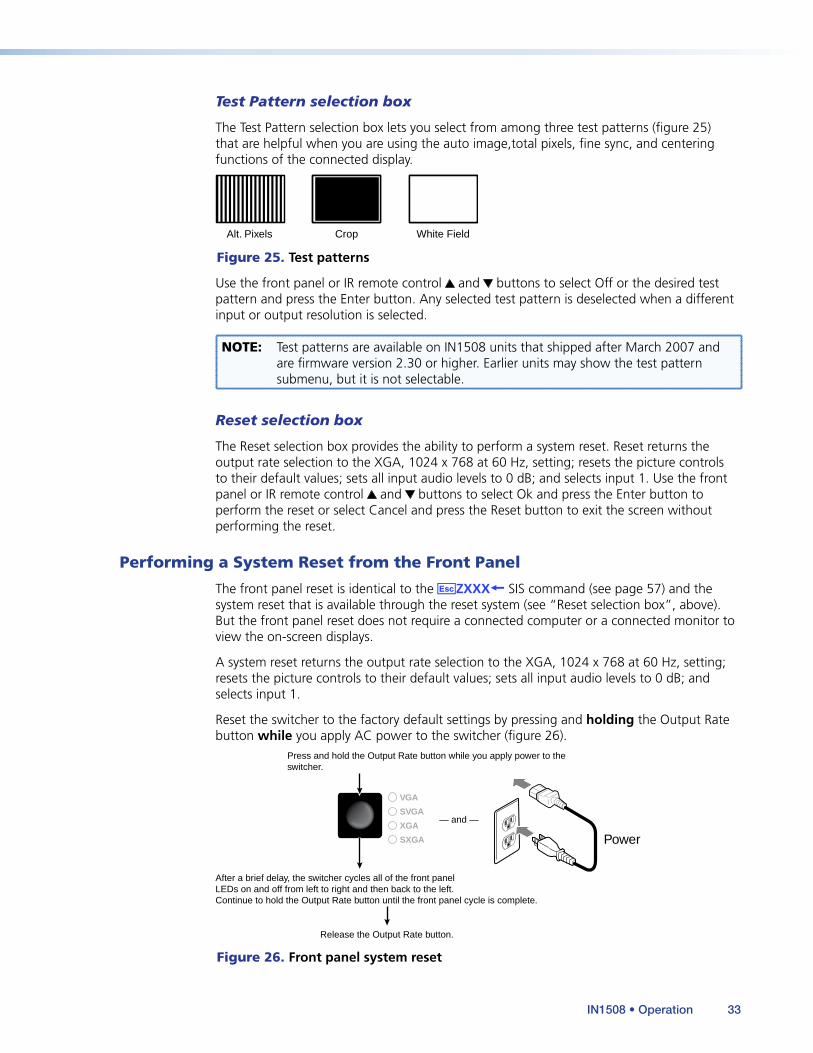
Test Pattern selection box
The Test Pattern selection box lets you select from among three test patterns (figure 25) that are helpful when you are using the auto image,total pixels, fine sync, and centering functions of the connected display.
Alt. Pixels Crop White Field
Figure 25. Test patterns
Use the front panel or IR remote control and buttons to select Off or the desired test pattern and press the Enter button. Any selected test pattern is deselected when a different input or output resolution is selected.
NOTE: Test patterns are available on IN1508 units that shipped after March 2007 and are firmware version 2.30 or higher. Earlier units may show the test pattern submenu, but it is not selectable.
Reset selection box
The Reset selection box provides the ability to perform a system reset. Reset returns the output rate selection to the XGA, 1024 x 768 at 60 Hz, setting; resets the picture controls to their default values; sets all input audio levels to 0 dB; and selects input 1. Use the front panel or IR remote control and buttons to select Ok and press the Enter button to perform the reset or select Cancel and press the Reset button to exit the screen without performing the reset.
Performing a System Reset from the Front Panel
The front panel reset is identical to the EZXXX} SIS command (see page 57) and the system reset that is available through the reset system (see “Reset selection box”, above). But the front panel reset does not require a connected computer or a connected monitor to view the on-screen displays.
A system reset returns the output rate selection to the XGA, 1024 x 768 at 60 Hz, setting; resets the picture controls to their default values; sets all input audio levels to 0 dB; and selects input 1.
Reset the switcher to the factory default settings by pressing and holding the Output Rate button while you apply AC power to the switcher (figure 26).
Power
VGA
SVGA
XGA
SXGA
Press and hold the Output Rate button while you apply power to the switcher.
After a brief delay, the switcher cycles all of the front panel LEDs on and off from left to right and then back to the left.Continue to hold the Output Rate button until the front panel cycle is complete.
Release the Output Rate button.
— and —
Figure 26. Front panel system reset
IN1508 • Operation 33
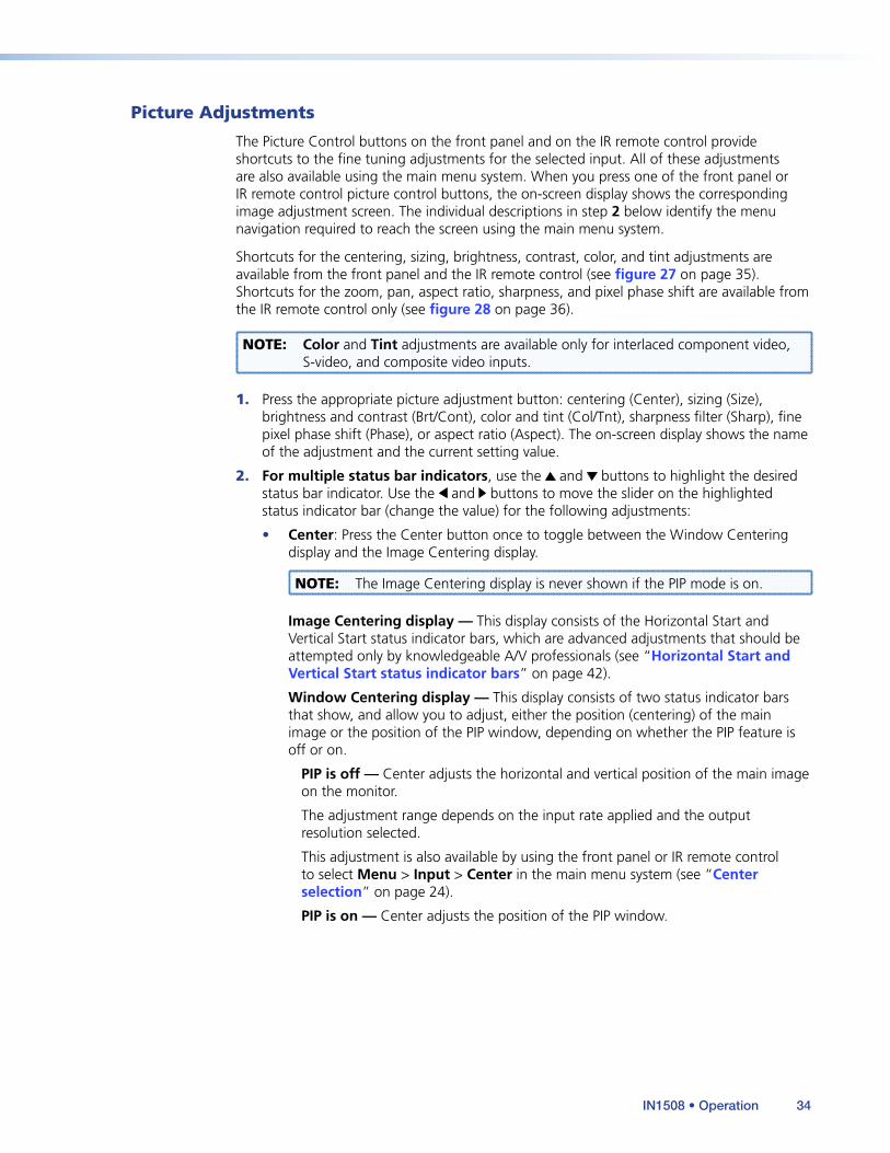
Picture Adjustments
The Picture Control buttons on the front panel and on the IR remote control provide shortcuts to the fine tuning adjustments for the selected input. All of these adjustments are also available using the main menu system. When you press one of the front panel or IR remote control picture control buttons, the on-screen display shows the corresponding image adjustment screen. The individual descriptions in step 2 below identify the menu navigation required to reach the screen using the main menu system.
Shortcuts for the centering, sizing, brightness, contrast, color, and tint adjustments are available from the front panel and the IR remote control (see figure 27 on page 35). Shortcuts for the zoom, pan, aspect ratio, sharpness, and pixel phase shift are available from the IR remote control only (see figure 28 on page 36).
NOTE: Color and Tint adjustments are available only for interlaced component video, S-video, and composite video inputs.
1. Press the appropriate picture adjustment button: centering (Center), sizing (Size), brightness and contrast (Brt/Cont), color and tint (Col/Tnt), sharpness filter (Sharp), fine pixel phase shift (Phase), or aspect ratio (Aspect). The on-screen display shows the name of the adjustment and the current setting value.
2. For multiple status bar indicators, use the and buttons to highlight the desired status bar indicator. Use the and buttons to move the slider on the highlighted status indicator bar (change the value) for the following adjustments:
• Center: Press the Center button once to toggle between the Window Centering display and the Image Centering display.
NOTE: The Image Centering display is never shown if the PIP mode is on.
Image Centering display — This display consists of the Horizontal Start and Vertical Start status indicator bars, which are advanced adjustments that should be attempted only by knowledgeable A/V professionals (see “Horizontal Start and Vertical Start status indicator bars” on page 42).
Window Centering display — This display consists of two status indicator bars that show, and allow you to adjust, either the position (centering) of the main image or the position of the PIP window, depending on whether the PIP feature is off or on.
PIP is off — Center adjusts the horizontal and vertical position of the main image on the monitor.
The adjustment range depends on the input rate applied and the output resolution selected.
This adjustment is also available by using the front panel or IR remote control to select Menu > Input > Center in the main menu system (see “Center selection” on page 24).
PIP is on — Center adjusts the position of the PIP window.
IN1508 • Operation 34
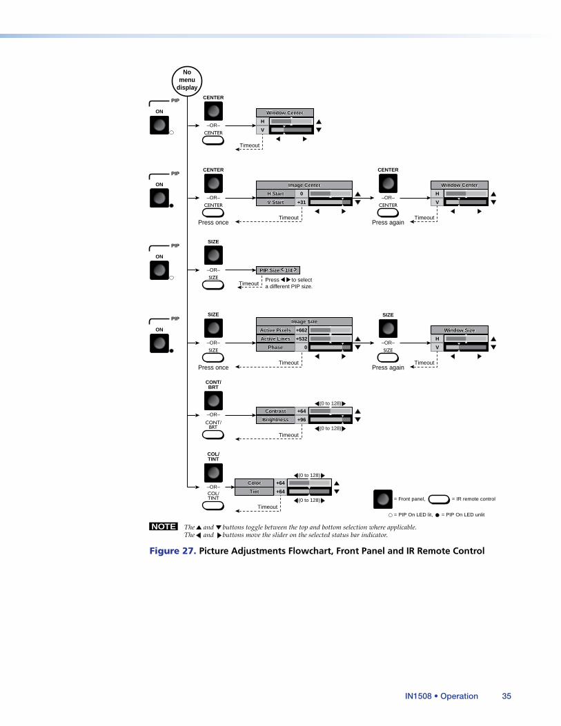
NOTE The and buttons toggle between the top and bottom selection where applicable.The and buttons move the slider on the selected status bar indicator.
Nomenu
display
Press once Press again
= Front panel, = IR remote control
= PIP On LED lit, = PIP On LED unlit
CENTER
–OR–
CENTER
CONT/BRT
CENTER
SIZE
CONT/BRT
–OR–
COL/TINT
COL/TINT
–OR–
Contrast
Brightness +96
+64
(0 to 128)
(0 to 128)
SIZE
–OR–
SIZE
SIZE
–OR–
Color
Tint +64
+64
(0 to 128)
(0 to 128)
V
H
Timeout
Timeout
H Start
V Start +31
0
Timeout
Timeout
–OR–
Press againPress once
CENTER
Window Center
V
H
Timeout
Window Size
Image Center
CENTER
–OR–
CENTER V
H
Timeout
Window Center
SIZE
Active Pixels
Phase 0
+662
Active Lines +532
Timeout
–OR–
SIZE
Image Size
PIP Size < 1/4 >
Contrast
Brightness
Color
Tint
H Start
V Start
Window Center
Window Size
Image Center
Window Center
Active Pixels
Phase
Active Lines
Image Size
PIP Size < 1/4 >
TimeoutPress to selecta different PIP size.
PIP
ON
PIP
ON
PIP
ON
PIP
ON
Figure 27. Picture Adjustments Flowchart, Front Panel and IR Remote Control
IN1508 • Operation 35

NOTE The and buttons toggle between the top and bottom selection where applicable. The and buttons move the slider on the selected status bar indicator.
No menu
display
= IR remote control
ASPECT RATIO
Sharpness
Aspect Ratio 4:3
+32
(0 to 63) SHARP
PHASE
Phase +64
(0 to 128)
Zoom
Pan
Sharpness
Aspect Ratio 4:3
Phase
Zoom
Pan V
H
Timeout
Timeout
Timeout
ZOOM
PAN
Timeout
Timeout Press to change the aspect ratio.
Figure 28. Picture Adjustments Flowchart, IR Remote Control
• Size: The Size button calls one of three displays, depending on whether PIP mode is on or off.
PIP is on — Size displays a single status indicator bar that allows you to cycle through the 1/4, 1/9, 1/16, and 1/25 sizes of the PIP window. Use the and buttons to cycle through the options.
This adjustment is also available by using the front panel or IR remote control to select Menu > Advanced > PIP Mode in the main menu system (see “PIP Mode selection box”, on page 32).
PIP is off — Size toggles between the Image Size display and the Window Size display.
Image Size display — This display consists of the Active Pixels, Active lines, and Phase status indicator bars, which are advanced adjustments that should be attempted only by knowledgeable A/V professionals (see “Active Pixels and Active Lines status indicator bars” on page 43 and “Phase status indicator bar” on page 45).
Window Size display — This display consists of two status indicator bars that show, and allow you to adjust, either the position (centering) of the main image or position of the PIP window, depending on whether the PIP feature is off or on.
The adjustment range depends on the input rate applied and the output resolution selected.
This adjustment is also available by using the front panel or IR remote control to select Menu > Input > Size in the main menu system (see “Size selection”, on page 25).
IN1508 • Operation 36
• Brightness/Contrast: Brightness adjusts the light intensity of the image on the screen. Contrast adjusts the difference between the brightest and darkest settings of the input signal.
The brightness adjustment is also available by using the front panel or IR remote control to select Menu > Picture > Brightness in the main menu system (see “Brightness status indicator bar” on page 26).
The contrast adjustment is also available by using the front panel or IR remote control to select Menu > Picture > Contrast in the main menu system (see “Contrast status indicator bar” on page 26).
• Color/Tint: Color increases and decreases the color intensity of the picture. Tint is a relative measure of the amount of white in a given color and adjusts the color of the picture toward red or green.
The color adjustment is also available by using the front panel or IR remote control to select Menu > Picture > Color in the main menu system (see “Color status indicator bar” on page 26).
The tint adjustment is also available by selecting Menu > Picture > Tint in the main menu system (see “Tint status indicator bar” on page 27).
• Zoom (IR remote control only): Zoom enlarges a portion of the scaled image.
This adjustment is also available by using the front panel or IR remote control to select Menu > Input > Zoom in the main menu system (see “Zoom selection”).
• Pan (IR remote control only): Pan shifts the center of the image on an image that has been zoomed in on.
NOTE: Pan is available only for an image that has been zoomed in.
This adjustment is also available by using the front panel or IR remote control to select Menu > Input > Pan in the main menu system (see “Pan selection”).
• Sharpness filter (IR remote control only): The adjustment range is from 0 to 128.
This adjustment is also available by using the front panel or IR remote control to select Menu > Picture > Sharpness in the main menu system (see “Sharpness status indicator bar” on page 27).
• Fine pixel phase (IR remote control only): The adjustment range is from 0 to 31.
This adjustment is also available by using the front panel or IR remote control to select Menu > Input > Advance > Phase in the main menu system (see “Phase status indicator bar” on page 45).
NOTE: Pixel phase is available only for YUVp, HDTV, and RGB inputs.
3. For the aspect ratio selection box, use the and buttons to toggle back and forth between the two selections: 4:3 and 16:9.
This adjustment is also available by using the front panel or IR remote control to select Menu > Input > Aspect in the main menu system (see “Aspect ratio selection” on page 25).
4. Repeat steps 1 and 2 for each image adjustment to be made for that input.
5. If you want to set picture adjustment on another input, press the appropriate input button.
IN1508 • Operation 37
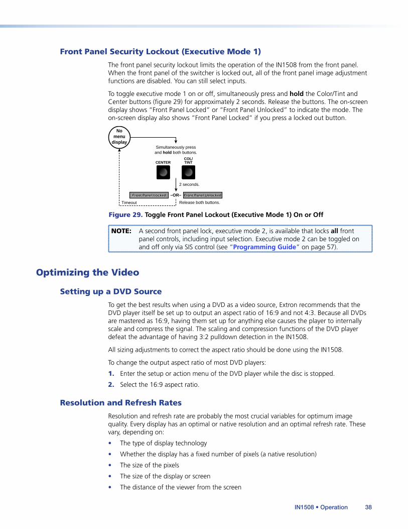
Front Panel Security Lockout (Executive Mode 1)
The front panel security lockout limits the operation of the IN1508 from the front panel. When the front panel of the switcher is locked out, all of the front panel image adjustment functions are disabled. You can still select inputs.
To toggle executive mode 1 on or off, simultaneously press and hold the Color/Tint and Center buttons (figure 29) for approximately 2 seconds. Release the buttons. The on-screen display shows “Front Panel Locked” or “Front Panel Unlocked” to indicate the mode. The on-screen display also shows “Front Panel Locked” if you press a locked out button.
Timeout
Simultaneously pressand hold both buttons.
2 seconds.
Release both buttons.
Nomenu
display
CENTERCOL/TINT
Front Panel Locked Front Panel Unlocked–OR–Front Panel Locked Front Panel Unlocked
Figure 29. Toggle Front Panel Lockout (Executive Mode 1) On or Off
NOTE: A second front panel lock, executive mode 2, is available that locks all front panel controls, including input selection. Executive mode 2 can be toggled on and off only via SIS control (see “Programming Guide” on page 57).
Optimizing the Video
Setting up a DVD Source
To get the best results when using a DVD as a video source, Extron recommends that the DVD player itself be set up to output an aspect ratio of 16:9 and not 4:3. Because all DVDs are mastered as 16:9, having them set up for anything else causes the player to internally scale and compress the signal. The scaling and compression functions of the DVD player defeat the advantage of having 3:2 pulldown detection in the IN1508.
All sizing adjustments to correct the aspect ratio should be done using the IN1508.
To change the output aspect ratio of most DVD players:
1. Enter the setup or action menu of the DVD player while the disc is stopped.
2. Select the 16:9 aspect ratio.
Resolution and Refresh Rates
Resolution and refresh rate are probably the most crucial variables for optimum image quality. Every display has an optimal or native resolution and an optimal refresh rate. These vary, depending on:
• The type of display technology
• Whether the display has a fixed number of pixels (a native resolution)
• The size of the pixels
• The size of the display or screen
• The distance of the viewer from the screen
IN1508 • Operation 38
Selecting the Optimum Resolution and Refresh Rate for Fixed Pixel Displays
Display devices that are based on LCD, DLP, D-ILA, and plasma technology have a specific number of pixels, a native resolution. These displays typically can show higher or lower resolution signals, but can do so only by scaling the image up or down to the native resolution. To avoid additional image scaling by the display (and more processing is inherently bad for image quality), it is important to know the native resolution of your display.
Check the operation manual for the display to determine its native resolution. Set the switcher to match this native resolution. The refresh rate of the switcher should be set to 60 Hz for most LCD, plasma, D-ILA, and DLP projectors.
NOTE: Higher refresh rates are not recommended for these display technologies. They usually do not improve the image and may cause compatibility problems.
For best results:
1. Set the output resolution and refresh rate of the switcher to match the native resolution of your display.
2. Output the White Field test pattern and then execute the auto image function of your display (this function may be called auto adjust or auto setup).
3. Output the Alternating Pixels test pattern and use the clocking or total pixels adjustment of your display to eliminate any vertical bars in the display.
4. While still outputting the Alternating Pixels test pattern, use the fine sync or phase adjustment of your display to eliminate any remaining noise.
5. Output the Crop test pattern and use the centering of shift controls of your display to center the image so that all four sides of the crop lines are visible.
6. Turn the test patterns off.
IN1508 • Operation 39

Input Submenu > Advanced Selections
Figure 30 shows the selections that are available from the Input > Advanced screen. The switcher automatically adjusts for different input and output modes. However, if the input signal has slightly different timing or is non-standard, some settings may need to be manually adjusted. All settings for each input and output mode (including non-standard input modes) are stored in non-volatile memory so that the adjustments do not need to be repeated after the settings are optimized.
Timeout
Timeout
No menu
display
INPUT
Menu Menu
Timeout
Menu Enter
Menu
Size
Pan
Aspect
Advanced
(Variable*)
(Variable*)
(Variable*)
(0 to 31)
Total Pixels +864
+556
+696
47
16Phase
H-Start
Active Pixels
Active Lines
Enter
Menu
Center
Zoom
Size
Pan
Aspect
Advanced
Total Pixels
Phase
H-Start
Active Pixels
Active Lines
Center
Zoom
(0 to 200)Inputs 5 - 5
(0 to 62)Inputs 1 - 4
V-Start 31V-Start (0 to 31)Inputs 1 - 4
* These variables are dependent on the input resolution and output resolution.
(0 to 85)Inputs 5 - 8
Figure 30. Input Submenu > Advanced Selections
To select one of the advanced settings, use the Menu or button to highlight the desired status indicator bar.
NOTE: The Advanced settings available from the Input submenu are a comprehensive set of adjustments to optimize the switcher for non-standard video inputs. Most users do not encounter such signals. For those users who do, the switcher automatically adjusts these settings. The automatic adjustments of the switcher are adequate for most inputs.
IN1508 • Operation 40
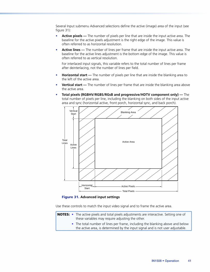
Several Input submenu Advanced selections define the active (image) area of the input (see figure 31):
• Active pixels — The number of pixels per line that are inside the input active area. The baseline for the active pixels adjustment is the right edge of the image. This value is often referred to as horizontal resolution.
• Active lines — The number of lines per frame that are inside the input active area. The baseline for the active lines adjustment is the bottom edge of the image. This value is often referred to as vertical resolution.
For interlaced input signals, this variable refers to the total number of lines per frame after deinterlacing, not the number of lines per field.
• Horizontal start — The number of pixels per line that are inside the blanking area to the left of the active area.
• Vertical start — The number of lines per frame that are inside the blanking area above the active area.
• Total pixels (RGBHV/RGBS/RGsB and progressive/HDTV component only) — The total number of pixels per line, including the blanking on both sides of the input active area and sync (horizontal active, front porch, horizontal sync, and back porch).
Active Pixels
Total Pixels
TotalLines
ActiveLines
VerticalStart
HorizontalStart
Active Area
Blanking Area
Figure 31. Advanced input settings
Use these controls to match the input video signal and to frame the active area.
NOTES: • The active pixels and total pixels adjustments are interactive. Setting one of these variables may require adjusting the other.
• The total number of lines per frame, including the blanking above and below the active area, is determined by the input signal and is not user adjustable.
IN1508 • Operation 41
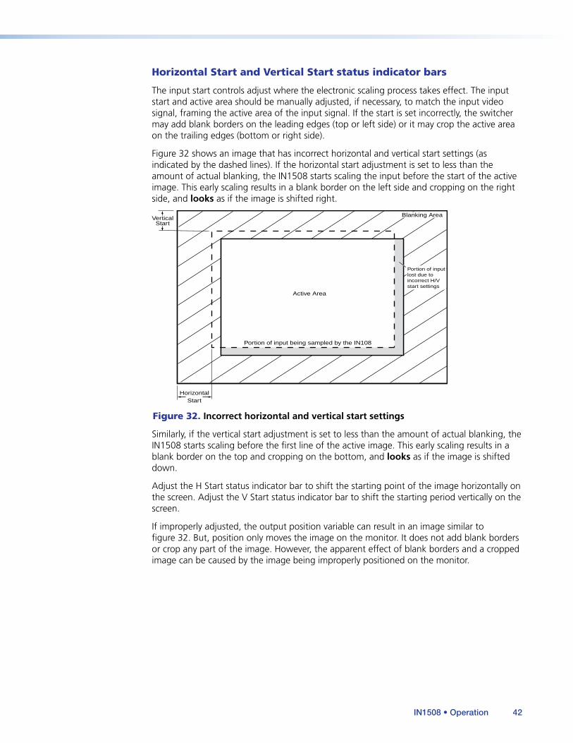
Horizontal Start and Vertical Start status indicator bars
The input start controls adjust where the electronic scaling process takes effect. The input start and active area should be manually adjusted, if necessary, to match the input video signal, framing the active area of the input signal. If the start is set incorrectly, the switcher may add blank borders on the leading edges (top or left side) or it may crop the active area on the trailing edges (bottom or right side).
Figure 32 shows an image that has incorrect horizontal and vertical start settings (as indicated by the dashed lines). If the horizontal start adjustment is set to less than the amount of actual blanking, the IN1508 starts scaling the input before the start of the active image. This early scaling results in a blank border on the left side and cropping on the right side, and looks as if the image is shifted right.
VerticalStart
HorizontalStart
Active Area
Blanking Area
Portion of input being sampled by the IN108
Portion of inputlost due toincorrect H/Vstart settings
Figure 32. Incorrect horizontal and vertical start settings
Similarly, if the vertical start adjustment is set to less than the amount of actual blanking, the IN1508 starts scaling before the first line of the active image. This early scaling results in a blank border on the top and cropping on the bottom, and looks as if the image is shifted down.
Adjust the H Start status indicator bar to shift the starting point of the image horizontally on the screen. Adjust the V Start status indicator bar to shift the starting period vertically on the screen.
If improperly adjusted, the output position variable can result in an image similar to figure 32. But, position only moves the image on the monitor. It does not add blank borders or crop any part of the image. However, the apparent effect of blank borders and a cropped image can be caused by the image being improperly positioned on the monitor.
IN1508 • Operation 42
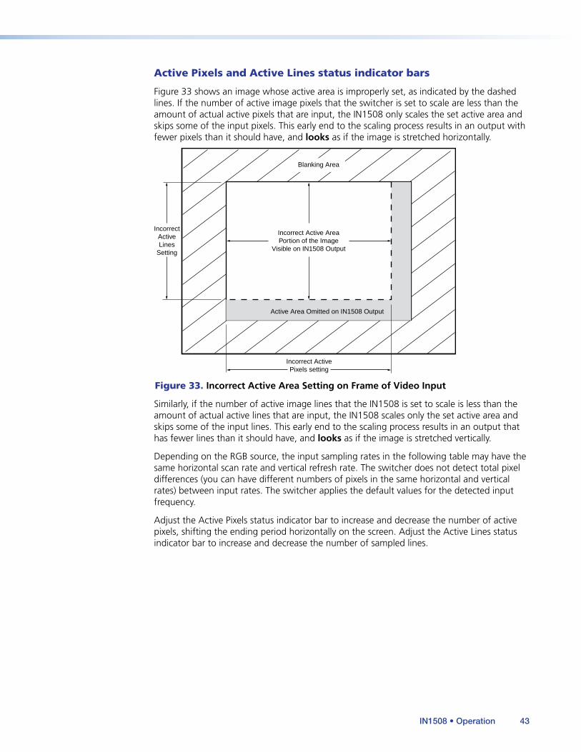
Active Pixels and Active Lines status indicator bars
Figure 33 shows an image whose active area is improperly set, as indicated by the dashed lines. If the number of active image pixels that the switcher is set to scale are less than the amount of actual active pixels that are input, the IN1508 only scales the set active area and skips some of the input pixels. This early end to the scaling process results in an output with fewer pixels than it should have, and looks as if the image is stretched horizontally.
Incorrect ActivePixels setting
IncorrectActiveLines
Setting
Incorrect Active AreaPortion of the Image
Visible on IN1508 Output
Active Area Omitted on IN1508 Output
Blanking Area
Figure 33. Incorrect Active Area Setting on Frame of Video Input
Similarly, if the number of active image lines that the IN1508 is set to scale is less than the amount of actual active lines that are input, the IN1508 scales only the set active area and skips some of the input lines. This early end to the scaling process results in an output that has fewer lines than it should have, and looks as if the image is stretched vertically.
Depending on the RGB source, the input sampling rates in the following table may have the same horizontal scan rate and vertical refresh rate. The switcher does not detect total pixel differences (you can have different numbers of pixels in the same horizontal and vertical rates) between input rates. The switcher applies the default values for the detected input frequency.
Adjust the Active Pixels status indicator bar to increase and decrease the number of active pixels, shifting the ending period horizontally on the screen. Adjust the Active Lines status indicator bar to increase and decrease the number of sampled lines.
IN1508 • Operation 43
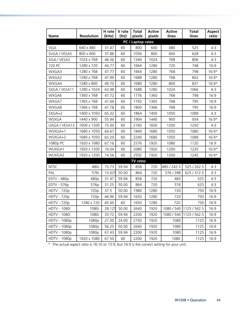
Name ResolutionH rate(kHz)
V rate(Hz)
Activepixels
Activelines
Aspectratio
Totalpixels
Totallines
640 x 480 60
800 x 600
1024 x 768
1280 x 720
1280 x 768
1280 x 768
1280 x 800
1280 x 1024
1360 x 768
1365 x 768
1366 x 768
1400 x 1050
1440 x 900
1600 x 1200
1680 x 1050
1680 x 1050
1920 x 1080
1920 x 1200
1920 x 1200
60
60
60
60
60
60
60
60
60
60
60
60
60
60
60
60
60
60
800
1056
1344
1664
1664
1688
1680
1688
1776
1792
1800
1864
1904
2160
1840
2240
2576
2080
2592
480
600
768
720
768
768
800
1024
768
768
768
1050
900
1200
1050
1050
1080
1200
1200
640
800
1024
1280
1280
1280
1280
1280
1360
1365
1366
1400
1440
1600
1680
1680
1920
1920
1920
525
628
806
748
798
802
831
1066
798
795
795
1089
934
1250
1080
1089
1120
1235
1245
4:3
4:3
4:3
16:9
16:9*
16:9*
16:9*
4:3
16:9
16:9
16:9
4:3
16:9*
4:3
16:9*
16:9*
16:9
16:9*
16:9*
31.47
37.88
48.36
44.77
47.77
47.99
49.70
63.98
47.72
47.69
47.78
65.32
55.94
75.00
64.67
65.29
67.16
74.04
74.56
VGA
SVGA / VESA5
XGA / VESA3
1280 x 720 60 1650 7201280 750 16:945.00HDTV - 720p
720 PC
WXGA3
WXGA2
WXGA4
WXGA6
SXGA / VESA11
WXGA7
WXGA8
SXGA+2
WSXGA
UXGA / VESA13
WSXGA+1
WSXGA+2
1920 x 1080 60 2200 10801920 1125 16:967.50HDTV - 1080p
1080p PC
WUXGA2
WUXGA1
PC / Laptop rates
480i 59.94
480p
720p
1080i
59.94
50.00
50.00
858
858
1980
2640
2200
485 / 242.5
483
720
1080 / 540
720
720
1280
1920
525 / 262.5
525
750
1125 / 562.5
4:3
4:3
16:9
16:9
15.73
31.47
37.5
28.125
NTSC
EDTV - 480p
576i 50.00 864 576 / 288720 625 / 312.5 4:315.625PAL
HDTV - 720p
576p 50.00 864 576720 625 4:331.25EDTV - 576p
HDTV - 1080i
720p 59.94 1650
2640
2200
2750
7201280 750 16:944.96HDTV - 720p
* The actual aspect ratio is 16:10 or 15:9, but 16:9 is the correct setting for your unit.
1080i 59.94 1080 / 5401920 1125 / 562.5 16:933.72HDTV - 1080i
1080p 24.00 10801920 1125 16:927.00HDTV - 1080p
1080p 50.00 10801920 1125 16:956.25HDTV - 1080p
1080p 59.94 10801920 1125 16:967.43HDTV - 1080p
TV rates
IN1508 • Operation 44
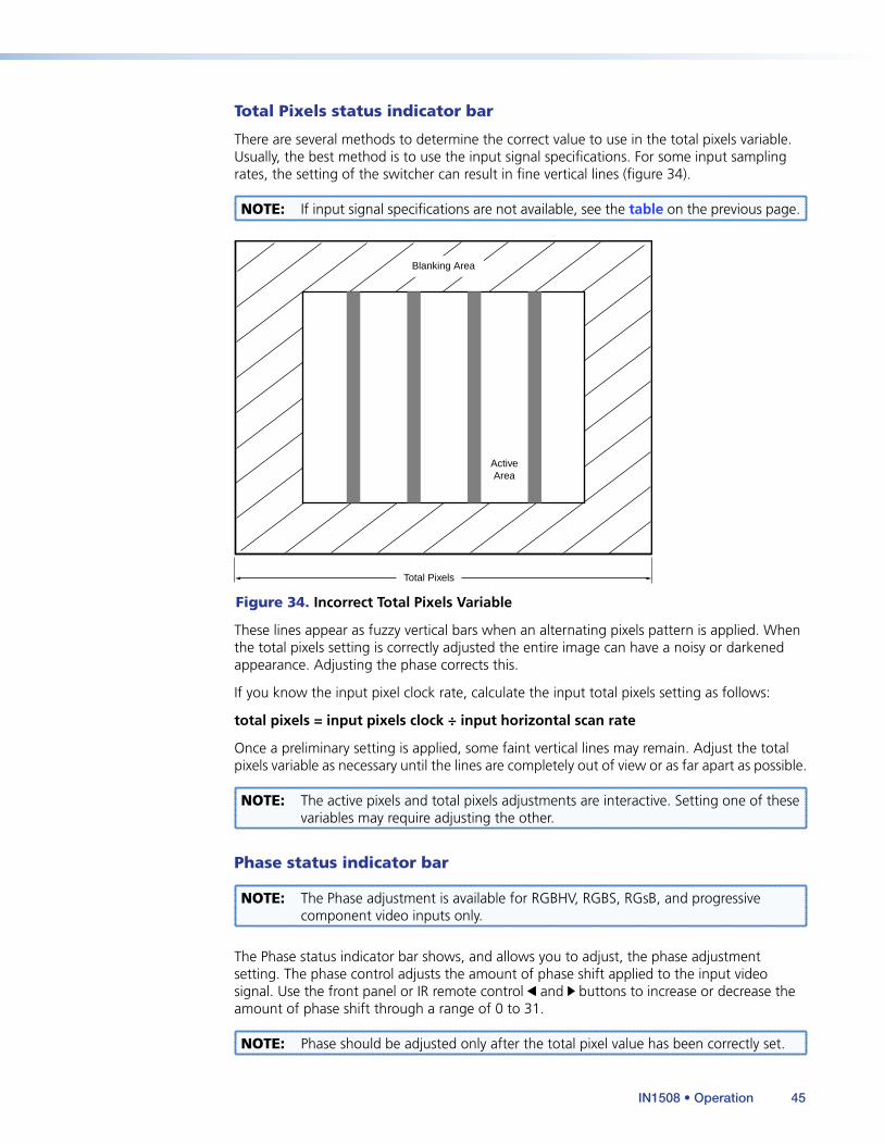
Total Pixels status indicator bar
There are several methods to determine the correct value to use in the total pixels variable. Usually, the best method is to use the input signal specifications. For some input sampling rates, the setting of the switcher can result in fine vertical lines (figure 34).
NOTE: If input signal specifications are not available, see the table on the previous page.
Total Pixels
ActiveArea
Blanking Area
Figure 34. Incorrect Total Pixels Variable
These lines appear as fuzzy vertical bars when an alternating pixels pattern is applied. When the total pixels setting is correctly adjusted the entire image can have a noisy or darkened appearance. Adjusting the phase corrects this.
If you know the input pixel clock rate, calculate the input total pixels setting as follows:
total pixels = input pixels clock ÷ input horizontal scan rate
Once a preliminary setting is applied, some faint vertical lines may remain. Adjust the total pixels variable as necessary until the lines are completely out of view or as far apart as possible.
NOTE: The active pixels and total pixels adjustments are interactive. Setting one of these variables may require adjusting the other.
Phase status indicator bar
NOTE: The Phase adjustment is available for RGBHV, RGBS, RGsB, and progressive component video inputs only.
The Phase status indicator bar shows, and allows you to adjust, the phase adjustment setting. The phase control adjusts the amount of phase shift applied to the input video signal. Use the front panel or IR remote control and buttons to increase or decrease the amount of phase shift through a range of 0 to 31.
NOTE: Phase should be adjusted only after the total pixel value has been correctly set.
IN1508 • Operation 45
Optimizing the AudioEach individual input audio level can be adjusted within a range of -65 dB to +9 dB, so there are no noticeable volume differences between sources and for the best headroom and signal-to-noise ratio. Adjust the audio gain and attenuation as follows:
1. Connect audio sources to all desired inputs and connect the audio output to an output device such as an audio player (see “Audio connections” on page 7).
2. Power on the audio sources, the switcher, and the audio players.
3. Select an input, listening to the audio with a critical ear.
4. As necessary, adjust each variable for the input (see “Input Gain/Attenuation status indicator bar” on page 30) for optimum audio quality.
5. Select each input in turn and repeat step 4 for each input.
TroubleshootingThis section gives recommendations on what to do if you have problems operating the switcher, and it provides examples and descriptions for some image problems you may encounter.
The following tips may help you in troubleshooting.
• Some symptoms may resemble others, so you may want to look through all of the examples before acting to solve the problem.
• Be prepared to backtrack in case the action taken does not solve the problem.
• It may help to keep notes and sketches in case the troubleshooting process gets lengthy. This will also give you something to discuss if you call for technical support.
• Try simplifying the system by eliminating components that may have introduced the problem or made it more complicated.
• For sync-related problems: Portable digital projectors are designed to operate close to the video source. Sync problems may result from using long cables or from improper termination. A sync adapter, such as the Extron ASTA (Active Sync Termination Adapter), may help solve these problems.
• For LCD and DLP projectors and plasma displays: In addition to the sync-related information above, check the user’s manual that came with the projector for troubleshooting tips, as well as for settings and adjustments. Each manufacturer may have its own terms, so look for terms like “auto setup”, “auto sync”, “pixel phase”, and “tracking.”
General Checks1. Ensure that all devices are plugged in and powered on. The switcher is receiving power
if one of the Input LEDs is lit.
2. Ensure that the input selected is active.
3. Ensure that the proper signal format is supplied.
4. Check the cabling and make corrections as necessary.
5. Call the Extron S3 Sales & Technical Support Hotline if necessary (see the last page of this manual for the phone number in your region of the world).
IN1508 • Operation 46

Specific Problems
The table below shows some common operating problems and their solutions.
Problem Possible cause Solution
No image appears.
Power. Ensure that the video source, the switcher, and the display are plugged into a live AC power source and that the switcher is turned on.
No video input. Check that the input device is outputting a video signal.
No video output. Press the Menu button. If the on-screen display does not appear, check the output connection.
The output signal is incompatible.
Select an output rate that is compatible with the display.
The output format is incompatible for the display.
Press and hold the front panel PIP On button while powering up the switcher. The IN1508 toggles between the RGB and YUV output formats.
The display may not accept the output sync format.
Check the sync capability of the display and select the correct output sync.
Freeze mode was entered when the image was black.
Issue the SIS command 0F to deactivate freeze mode.
Video may be muted. Issue the SIS command 0B to disable video mute.
No audio output.
Power. Ensure that the audio source, the switcher, and the amplifier/ speakers are plugged into a live AC power source and the switcher is turned on.
The source is incorrect. Ensure that the source is connected to the correct input and that the volume has not been turned down or muted.
The output is incorrect. The IN1508 outputs line level audio only. Ensure that it is connected to a mixer/amplifier or to amplified speakers.
Volume is too low. Increase the volume using the Audio submenu.
Audio may be muted. Issue the SIS command 0Z to disable audio mute.
The image is scrambled.
The output signal is incompatible.
Use the power up shortcuts to select an output format (RGB, component, and the like) and rate that are compatible with the display.
IN1508 • Operation 47
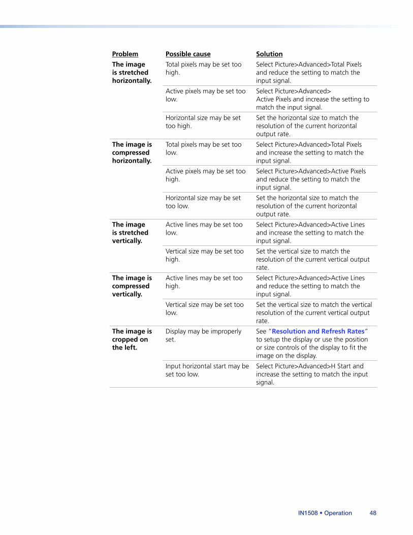
Problem Possible cause Solution
The image is stretched horizontally.
Total pixels may be set too high.
Select Picture>Advanced>Total Pixels and reduce the setting to match the input signal.
Active pixels may be set too low.
Select Picture>Advanced> Active Pixels and increase the setting to match the input signal.
Horizontal size may be set too high.
Set the horizontal size to match the resolution of the current horizontal output rate.
The image is compressed horizontally.
Total pixels may be set too low.
Select Picture>Advanced>Total Pixels and increase the setting to match the input signal.
Active pixels may be set too high.
Select Picture>Advanced>Active Pixels and reduce the setting to match the input signal.
Horizontal size may be set too low.
Set the horizontal size to match the resolution of the current horizontal output rate.
The image is stretched vertically.
Active lines may be set too low.
Select Picture>Advanced>Active Lines and increase the setting to match the input signal.
Vertical size may be set too high.
Set the vertical size to match the resolution of the current vertical output rate.
The image is compressed vertically.
Active lines may be set too high.
Select Picture>Advanced>Active Lines and reduce the setting to match the input signal.
Vertical size may be set too low.
Set the vertical size to match the vertical resolution of the current vertical output rate.
The image is cropped on the left.
Display may be improperly set.
See ”Resolution and Refresh Rates” to setup the display or use the position or size controls of the display to fit the image on the display.
Input horizontal start may be set too low.
Select Picture>Advanced>H Start and increase the setting to match the input signal.
IN1508 • Operation 48
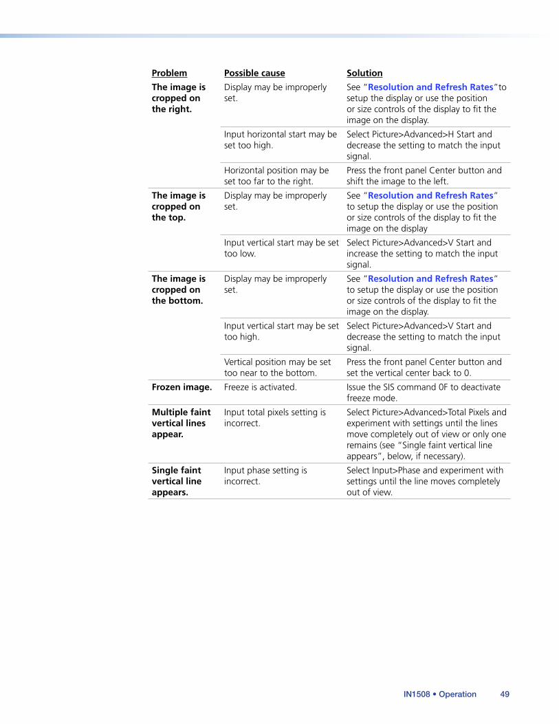
Problem Possible cause Solution
The image is cropped on the right.
Display may be improperly set.
See ”Resolution and Refresh Rates”to setup the display or use the position or size controls of the display to fit the image on the display.
Input horizontal start may be set too high.
Select Picture>Advanced>H Start and decrease the setting to match the input signal.
Horizontal position may be set too far to the right.
Press the front panel Center button and shift the image to the left.
The image is cropped on the top.
Display may be improperly set.
See ”Resolution and Refresh Rates” to setup the display or use the position or size controls of the display to fit the image on the display
Input vertical start may be set too low.
Select Picture>Advanced>V Start and increase the setting to match the input signal.
The image is cropped on the bottom.
Display may be improperly set.
See ”Resolution and Refresh Rates” to setup the display or use the position or size controls of the display to fit the image on the display.
Input vertical start may be set too high.
Select Picture>Advanced>V Start and decrease the setting to match the input signal.
Vertical position may be set too near to the bottom.
Press the front panel Center button and set the vertical center back to 0.
Frozen image. Freeze is activated. Issue the SIS command 0F to deactivate freeze mode.
Multiple faint vertical lines appear.
Input total pixels setting is incorrect.
Select Picture>Advanced>Total Pixels and experiment with settings until the lines move completely out of view or only one remains (see “Single faint vertical line appears”, below, if necessary).
Single faint vertical line appears.
Input phase setting is incorrect.
Select Input>Phase and experiment with settings until the line moves completely out of view.
IN1508 • Operation 49
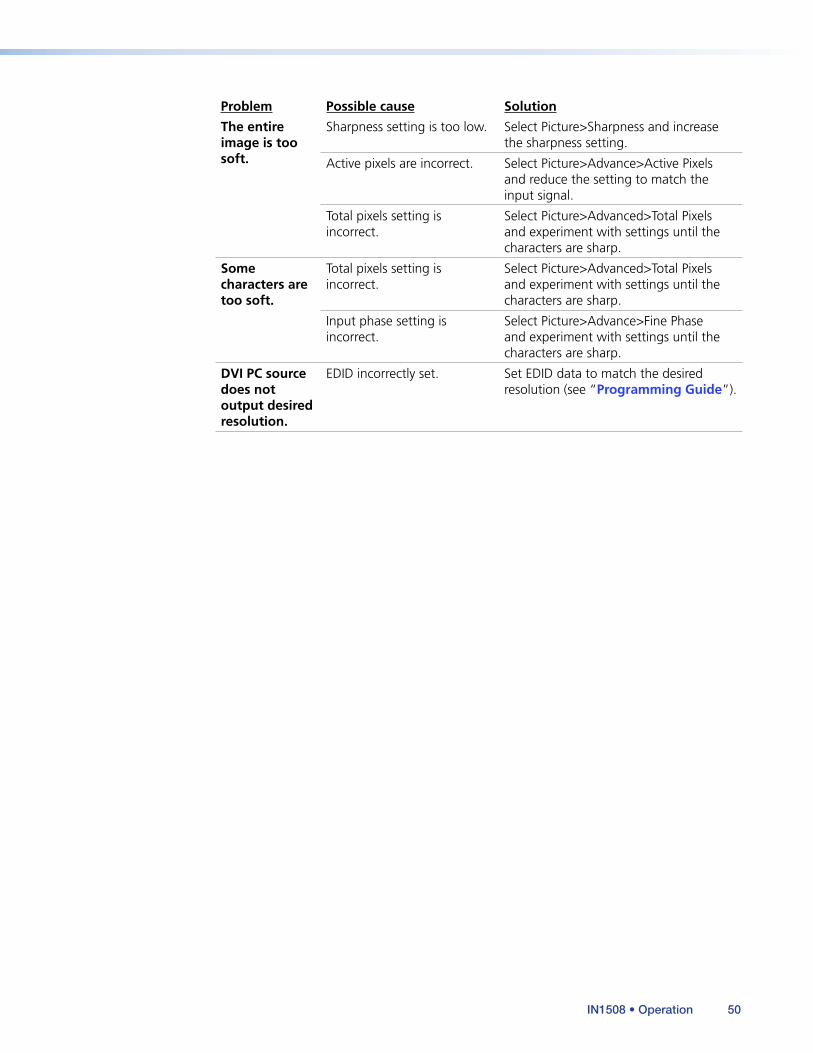
Problem Possible cause Solution
The entire image is too soft.
Sharpness setting is too low. Select Picture>Sharpness and increase the sharpness setting.
Active pixels are incorrect. Select Picture>Advance>Active Pixels and reduce the setting to match the input signal.
Total pixels setting is incorrect.
Select Picture>Advanced>Total Pixels and experiment with settings until the characters are sharp.
Some characters are too soft.
Total pixels setting is incorrect.
Select Picture>Advanced>Total Pixels and experiment with settings until the characters are sharp.
Input phase setting is incorrect.
Select Picture>Advance>Fine Phase and experiment with settings until the characters are sharp.
DVI PC source does not output desired resolution.
EDID incorrectly set. Set EDID data to match the desired resolution (see “Programming Guide”).
IN1508 • Operation 50
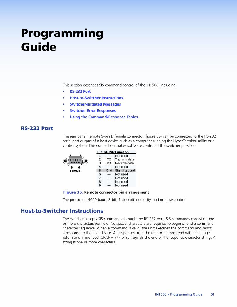
Programming Guide
This section describes SIS command control of the IN1508, including:
• RS-232 Port
• Host-to-Switcher Instructions
• Switcher-Initiated Messages
• Switcher Error Responses
• Using the Command/Response Tables
RS-232 PortThe rear panel Remote 9-pin D female connector (figure 35) can be connected to the RS-232 serial port output of a host device such as a computer running the HyperTerminal utility or a control system. This connection makes software control of the switcher possible.
5 1
9 6Female
RS-232 FunctionPin123456789
—TXRX—
Gnd————
Not usedTransmit dataReceive dataNot usedSignal groundNot usedNot usedNot usedNot used
Figure 35. Remote connector pin arrangement
The protocol is 9600 baud, 8-bit, 1 stop bit, no parity, and no flow control.
Host-to-Switcher InstructionsThe switcher accepts SIS commands through the RS-232 port. SIS commands consist of one or more characters per field. No special characters are required to begin or end a command character sequence. When a command is valid, the unit executes the command and sends a response to the host device. All responses from the unit to the host end with a carriage return and a line feed (CR/LF = ]), which signals the end of the response character string. A string is one or more characters.
IN1508 • Programming Guide 51
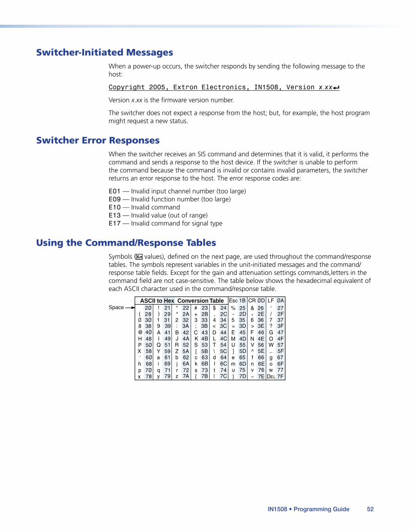
Switcher-Initiated MessagesWhen a power-up occurs, the switcher responds by sending the following message to the host:
Copyright 2005, Extron Electronics, IN1508, Version x.xx]
Version x.xx is the firmware version number.
The switcher does not expect a response from the host; but, for example, the host program might request a new status.
Switcher Error ResponsesWhen the switcher receives an SIS command and determines that it is valid, it performs the command and sends a response to the host device. If the switcher is unable to perform the command because the command is invalid or contains invalid parameters, the switcher returns an error response to the host. The error response codes are:
E01 — Invalid input channel number (too large) E09 — Invalid function number (too large) E10 — Invalid command E13 — Invalid value (out of range) E17 — Invalid command for signal type
Using the Command/Response TablesSymbols (X/ values), defined on the next page, are used throughout the command/response tables. The symbols represent variables in the unit-initiated messages and the command/response table fields. Except for the gain and attenuation settings commands,letters in the command field are not case-sensitive. The table below shows the hexadecimal equivalent of each ASCII character used in the command/response table.
ASCII to Hex Conversion Table
•
Space
IN1508 • Programming Guide 52

Symbol Definitions] = CR/LF (carriage return/line feed)
} = Carriage return (no line feed)
| = Pipe (can be used interchangeably with the } character)
• = Space (hard) character
E = Escape key (hex 1B)
W = Can be used interchangeable with the E character
X! = Input number 1 through 8
X@ = Switcher resolution (EDID):00 = Match output resolution (EDID only) 01 = 640 x 480 (VGA) 13 = 720p 02 = 800 x 600 (SVGA) 14 = 1080i 03 = 1024 x 768 (XGA) 15 = 1080p 04 = 1280 x 1024 (SXGA) 16 = 1280 x 768 05 = 1024 x 852 17 = 1440 x 900 06 = 1024 x 1024 18 = 1680 x 1050 07 = 1366 x 768 19 = 1280 x 800 08 = 1365 x 1024 20 = 852 x 480 09 = 1400 x 1050 21 = 1080p Sharp 10 = 1600 x 1200 (UXGA) 22 = 1920 x 1200 11 = 480p 23 = 1080p CVT 12 = 576p
X# = Video refresh rate:0 = Match output rate (EDID only) 1 = 50 Hz 3 = 75 Hz (24 Hz for 1080p) 2 = 60 Hz 4 = 59.94 Hz
X$ = On/off status (0 = off, 1 = on)
X% = Lock (Exec. mode) status (0 [unlocked], 1 [partial], or 2 [full])
X^ = Picture adjustment range (000 through 128)
X& = Horizontal shift range (000 through current horizontal output resolution)
X* = Vertical shift range (000 through current vertical output resolution)
X( = Sharpness level (00 through 128)
X1) = Horizontal start position (000 thru 200)
X1! = Vertical start position (000 thru {variable})
X1@ = Pixel phase value (0 to 31)
X1# = Gain value (numeric dB value, 0 to +9)
X1$ = Attenuation value (numeric dB value, –1 to –65)
X1% = Gain/attenuation (–65 dB to +9 dB, each step = 1 dB)
X1^ = Output volume (0 to 100)
X1& = Detected input signal standard (input 1 through 4 or 5): 0 = none 3 = NTSC 4.43 1 = NTSC 3.58 4 = SECAM 2 = PAL
X1* = Input 5 video type: 0 = Interlaced component 2 = HDTV 1 = Progressive component
X1( = PIP size:00 = 1/4 (default) 03 = 1/25 01 = 1/9 04 = Side-by-side normal 02 = 1/16 05 = Side-by-side full screen
X2) = Output video type: 0 = Y, B-Y, R-Y 2 = RGBS 1 = RGBHV 3 = RGsB
X2! = Output sync polarity: 0 = H–/V– 2 = H+/V– 1 = H–/V+ 3 = H+/V+
X2@ = Aspect ratio (0 = 4:3, 1 = 16:9)
X2# = Menu buttons:00 = Menu 03 = Left 01 = Up 04 = Right 02 = Down 05 = Enter
X2$ = Pixel and line values (The range depends on the input resolution applied and the output resolution selected).
X2% = Audio follow: 0 = Follow main window 2 = Toggle audio source 1 = Follow PIP window
X2^ = Window size (The range depends on the input resolution applied and the output resolution selected).
X2& = Test pattern: 0 = Off 2 = White field 1 = Alternating pixels 3 = Crop
IN1508 • Programming Guide 53
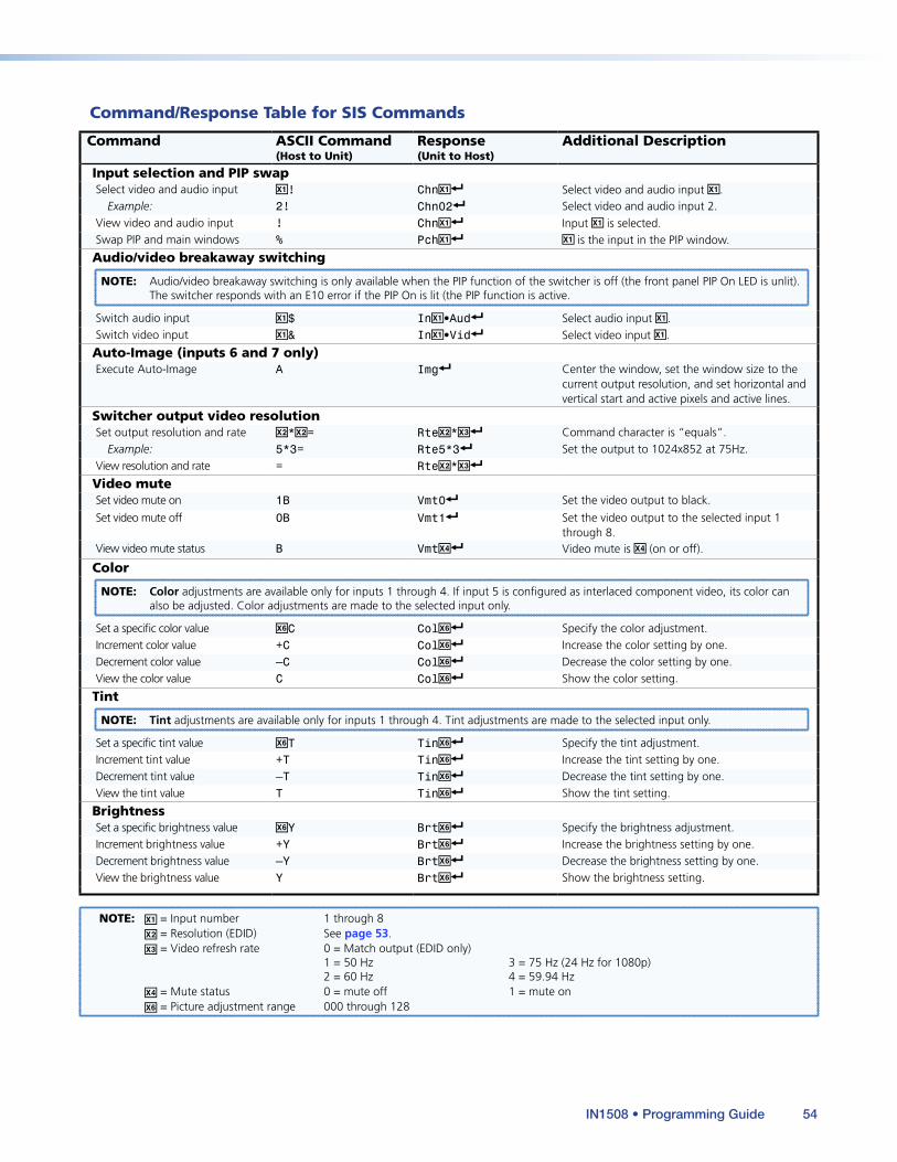
Command ASCII Command (Host to Unit)
Response (Unit to Host)
Additional Description
Input selection and PIP swapSelect video and audio input X!! ChnX!] Select video and audio input X!.
Example: 2! Chn02] Select video and audio input 2.View video and audio input ! ChnX!] Input X! is selected.Swap PIP and main windows % PchX!] X! is the input in the PIP window.
Audio/video breakaway switching
NOTE: Audio/video breakaway switching is only available when the PIP function of the switcher is off (the front panel PIP On LED is unlit). The switcher responds with an E10 error if the PIP On is lit (the PIP function is active.
Switch audio input X!$ InX!•Aud] Select audio input X!.Switch video input X!& InX!•Vid] Select video input X!.
Auto-Image (inputs 6 and 7 only)Execute Auto-Image A Img] Center the window, set the window size to the
current output resolution, and set horizontal and vertical start and active pixels and active lines.
Switcher output video resolutionSet output resolution and rate X@*X@= RteX@*X#] Command character is “equals”.
Example: 5*3= Rte5*3] Set the output to 1024x852 at 75Hz.View resolution and rate = RteX@*X#]
Video muteSet video mute on 1B Vmt0] Set the video output to black.
Set video mute off 0B Vmt1] Set the video output to the selected input 1 through 8.
View video mute status B VmtX$] Video mute is X$ (on or off).
Color
NOTE: Color adjustments are available only for inputs 1 through 4. If input 5 is configured as interlaced component video, its color can also be adjusted. Color adjustments are made to the selected input only.
Set a specific color value X^C ColX^] Specify the color adjustment.Increment color value +C ColX^] Increase the color setting by one.Decrement color value –C ColX^] Decrease the color setting by one.View the color value C ColX^] Show the color setting.
Tint
NOTE: Tint adjustments are available only for inputs 1 through 4. Tint adjustments are made to the selected input only.
Set a specific tint value X^T TinX^] Specify the tint adjustment.Increment tint value +T TinX^] Increase the tint setting by one.Decrement tint value –T TinX^] Decrease the tint setting by one.View the tint value T TinX^] Show the tint setting.
BrightnessSet a specific brightness value X^Y BrtX^] Specify the brightness adjustment.Increment brightness value +Y BrtX^] Increase the brightness setting by one.Decrement brightness value –Y BrtX^] Decrease the brightness setting by one.View the brightness value Y BrtX^] Show the brightness setting.
NOTE: X! = Input number 1 through 8 X@ = Resolution (EDID) See page 53. X# = Video refresh rate 0 = Match output (EDID only) 1 = 50 Hz 3 = 75 Hz (24 Hz for 1080p) 2 = 60 Hz 4 = 59.94 Hz X$ = Mute status 0 = mute off 1 = mute on X^ = Picture adjustment range 000 through 128
Command/Response Table for SIS Commands
IN1508 • Programming Guide 54
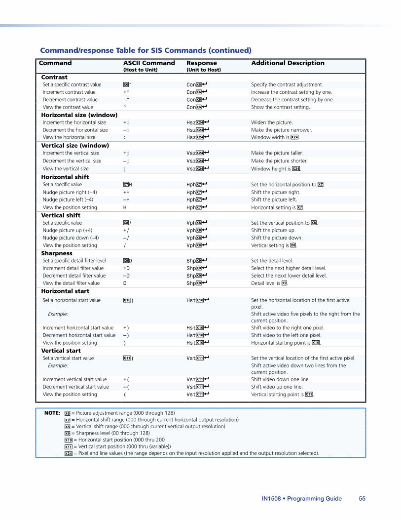
Command/response Table for SIS Commands (continued)
Command ASCII Command (Host to Unit)
Response (Unit to Host)
Additional Description
ContrastSet a specific contrast value X^^ ConX^] Specify the contrast adjustment.Increment contrast value +^ ConX^] Increase the contrast setting by one.Decrement contrast value –^ ConX^] Decrease the contrast setting by one.View the contrast value ^ ConX^] Show the contrast setting.
Horizontal size (window)Increment the horizontal size +: HszX2$] Widen the picture.Decrement the horizontal size –: HszX2$] Make the picture narrower.View the horizontal size : HszX2$] Window width is X2$.
Vertical size (window)Increment the vertical size +; VszX2$] Make the picture taller.
Decrement the vertical size –; VszX2$] Make the picture shorter.
View the vertical size ; VszX2$] Window height is X2$.
Horizontal shiftSet a specific value X&H HphX&] Set the horizontal position to X&.
Nudge picture right (+4) +H HphX&] Shift the picture right.Nudge picture left (–4) –H HphX&] Shift the picture left.
View the position setting H HphX&] Horizontal setting is X&.
Vertical shiftSet a specific value X*/ VphX*] Set the vertical position to X*.Nudge picture up (+4) +/ VphX*] Shift the picture up.Nudge picture down (–4) –/ VphX*] Shift the picture down.View the position setting / VphX*] Vertical setting is X*.
SharpnessSet a specific detail filter level X(D ShpX(] Set the detail level.Increment detail filter value +D ShpX(] Select the next higher detail level.Decrement detail filter value –D ShpX(] Select the nexxt lower detail level.View the detail filter value D ShpX(] Detail level is X(.
Horizontal startSet a horizontal start value X1)) HstX1)] Set the horizontal location of the first active
pixel.Example: Shift active video five pixels to the right from the
current position.Increment horizontal start value +) HstX1)] Shift video to the right one pixel.Decrement horizontal start value –) HstX1)] Shift video to the left one pixel.View the position setting ) HstX1)] Horizontal starting point is X1).
Vertical startSet a vertical start value X1!( VstX1!] Set the vertical location of the first active pixel.
Example: Shift active video down two lines from the current position.
Increment vertical start value +( VstX1!] Shift video down one line.Decrement vertical start value –( VstX1!] Shift video up one line.View the position setting ( VstX1!] Vertical starting point is X1!.
NOTE: X^ = Picture adjustment range (000 through 128) X& = Horizontal shift range (000 through current horizontal output resolution) X* = Vertical shift range (000 through current vertical output resolution) X( = Sharpness level (00 through 128) X1) = Horizontal start position (000 thru 200 X1! = Vertical start position (000 thru {variable}) X2$ = Pixel and line values (the range depends on the input resolution applied and the output resolution selected).
IN1508 • Programming Guide 55
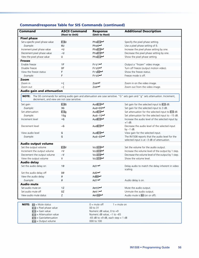
Command/response Table for SIS Commands (continued)
Command ASCII Command (Host to Unit)
Response (Unit to Host)
Additional Description
Pixel phaseSet a specific pixel phase value X1@U PhsX1@] Specify the pixel phase setting.
Example: 6U Phs6] Use a pixel phase setting of 6.Increment pixel phase value +U PhsX1@] Increase the pixel phase setting by one.Decrement pixel phase value –U PhsX1@] Decrease the pixel phase setting by one.View the pixel phase value U PhsX1@] Show the pixel phase setting.
FreezeEnable freeze 1F Frz1] Output a “frozen” video image.Disable freeze 0F Frz0] Turn off freeze (output motion video).View the freeze status F FrzX$] Show the freeze status.
Example: F Frz0] Freeze mode is off.
ZoomZoom in +{ Zom] Zoom in on the video image.Zoom out –{ Zom] Zoom out from the video image.
Audio gain and attenuation
NOTE: The SIS commands for setting audio gain and attenuation are case sensitive. “G” sets gain and “g” sets attenuation. Increment, decrement, and view are not case sensitive.
Set gain X1#G AudX1%] Set gain for the selected input to X1# dB.Example: 3G Aud+03] Set gain for the selected input to 3 dB.
Set attenuation X1$g AudX1%] Set attenuation for the selected input to X1$ dB.Example: 15g Aud–15] Set attenuation for the selected input to –15 dB.
Increment level +G AudX1%] Increase the audio level of the selected input by +1 dB.
Decrement level –G AudX1%] Decrease the audio level of the selected input by –1 dB.
View audio level G AudX1%] View gain for the selected input.Example: G Aud–03] The IN1508 reports that the audio level for the
selected input is at –3 dB of attenuation.
Audio output volumeSet the output volume X1^V VolX1^] Set the volume for the audio output.Increment the output volume +V VolX1^] Increase the volume level of the output by 1 step.Decrement the output volume –V VolX1^] Decrease the volume level of the output by 1 step.View the output volume V VolX1^] Show the volume level.
Audio delaySet the audio delay on 1@ Ad1] Delay audio to match the delay inherent in video
scaling.Set the audio delay off 0@ Ad0]
View the audio delay @ AdX$]
Example: @ Ad1] Audio delay is on.
Audio muteSet audio mute on 1Z Amt0] Mute the audio output.Set audio mute off 0Z Amt1] Unmute the audio output.View audio mute status Z AmtX$] Audio mute is X$ (on or off).
NOTE: X$ = Mute status 0 = mute off 1 = mute on X1@ = Pixel phase value 00 to 31 X1# = Gain value Numeric dB value, 0 to +9 X1$ = Attenuation value Numeric dB value, –1 to –65 X1% = Gain/attenuation -65 dB to +9 dB, each step = 1 dB X1^ = Output volume 000 to 100
IN1508 • Programming Guide 56
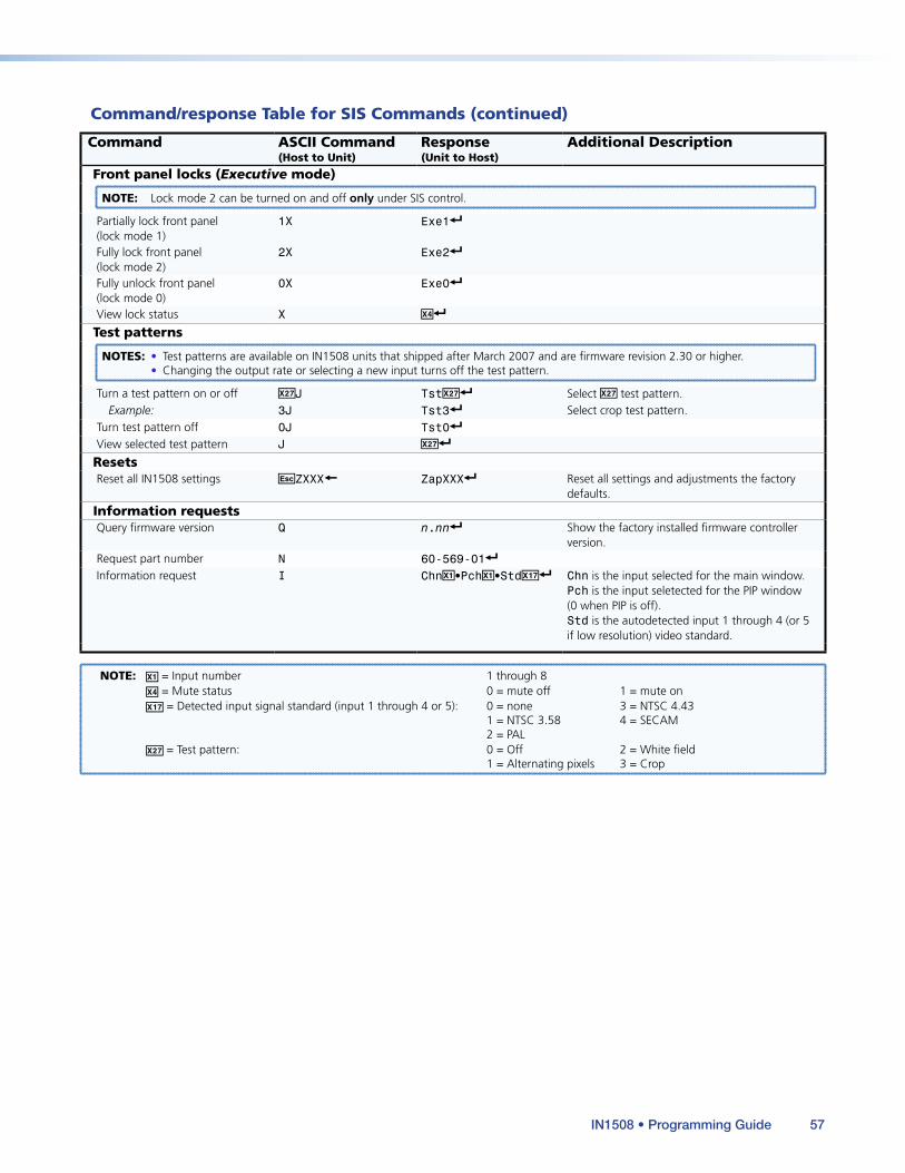
Command/response Table for SIS Commands (continued)
Command ASCII Command (Host to Unit)
Response (Unit to Host)
Additional Description
Front panel locks (Executive mode)
NOTE: Lock mode 2 can be turned on and off only under SIS control.
Partially lock front panel (lock mode 1)
1X Exe1]
Fully lock front panel (lock mode 2)
2X Exe2]
Fully unlock front panel (lock mode 0)
0X Exe0]
View lock status X X$]
Test patterns
NOTES: • Test patterns are available on IN1508 units that shipped after March 2007 and are firmware revision 2.30 or higher. • Changing the output rate or selecting a new input turns off the test pattern.
Turn a test pattern on or off X2&J TstX2&] Select X2& test pattern.Example: 3J Tst3] Select crop test pattern.
Turn test pattern off 0J Tst0]
View selected test pattern J X2&]
ResetsReset all IN1508 settings EZXXX} ZapXXX] Reset all settings and adjustments the factory
defaults.
Information requestsQuery firmware version Q n.nn] Show the factory installed firmware controller
version.Request part number N 60-569-01]
Information request I ChnX!•PchX!•StdX1&] Chn is the input selected for the main window. Pch is the input seletected for the PIP window (0 when PIP is off). Std is the autodetected input 1 through 4 (or 5 if low resolution) video standard.
NOTE: X! = Input number 1 through 8 X$ = Mute status 0 = mute off 1 = mute on X1& = Detected input signal standard (input 1 through 4 or 5): 0 = none 3 = NTSC 4.43 1 = NTSC 3.58 4 = SECAM 2 = PAL X2& = Test pattern: 0 = Off 2 = White field 1 = Alternating pixels 3 = Crop
IN1508 • Programming Guide 57
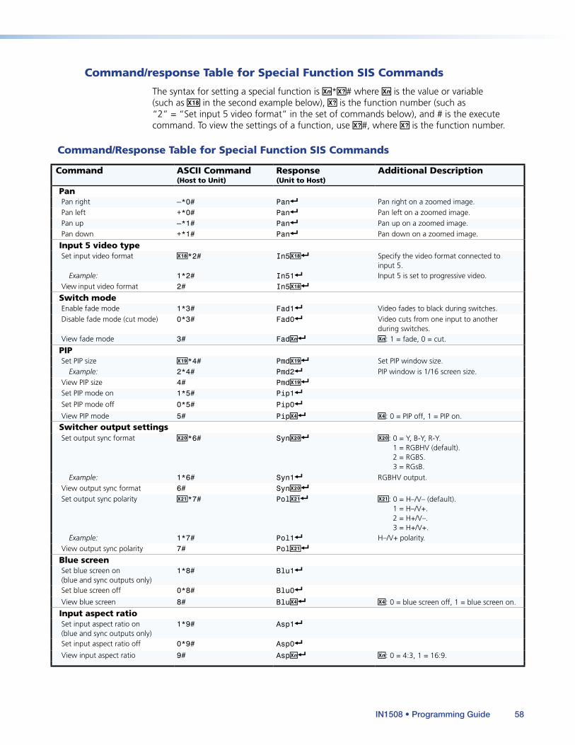
Command/response Table for Special Function SIS Commands
The syntax for setting a special function is X/*X?# where X/ is the value or variable (such as X1* in the second example below), X? is the function number (such as “2” = “Set input 5 video format” in the set of commands below), and # is the execute command. To view the settings of a function, use X?#, where X? is the function number.
Command/Response Table for Special Function SIS Commands
Command ASCII Command (Host to Unit)
Response (Unit to Host)
Additional Description
PanPan right –*0# Pan] Pan right on a zoomed image.Pan left +*0# Pan] Pan left on a zoomed image.Pan up –*1# Pan] Pan up on a zoomed image.Pan down +*1# Pan] Pan down on a zoomed image.
Input 5 video typeSet input video format X1**2# In5X1*] Specify the video format connected to
input 5.Example: 1*2# In51] Input 5 is set to progressive video.
View input video format 2# In5X1*]
Switch modeEnable fade mode 1*3# Fad1] Video fades to black during switches.Disable fade mode (cut mode) 0*3# Fad0] Video cuts from one input to another
during switches.View fade mode 3# FadX/] X/: 1 = fade, 0 = cut.
PIPSet PIP size X1(*4# PmdX1(] Set PIP window size.
Example: 2*4# Pmd2] PIP window is 1/16 screen size.View PIP size 4# PmdX1(]
Set PIP mode on 1*5# Pip1]
Set PIP mode off 0*5# Pip0]
View PIP mode 5# PipX$] X$: 0 = PIP off, 1 = PIP on.
Switcher output settingsSet output sync format X2)*6# SynX2)] X2): 0 = Y, B-Y, R-Y.
1 = RGBHV (default). 2 = RGBS. 3 = RGsB.
Example: 1*6# Syn1] RGBHV output.View output sync format 6# SynX2)]
Set output sync polarity X2!*7# PolX21] X2!: 0 = H–/V– (default). 1 = H–/V+. 2 = H+/V–. 3 = H+/V+.
Example: 1*7# Pol1] H–/V+ polarity.View output sync polarity 7# PolX2!]
Blue screenSet blue screen on (blue and sync outputs only)
1*8# Blu1]
Set blue screen off 0*8# Blu0]
View blue screen 8# BluX$] X$: 0 = blue screen off, 1 = blue screen on.
Input aspect ratioSet input aspect ratio on (blue and sync outputs only)
1*9# Asp1]
Set input aspect ratio off 0*9# Asp0]
View input aspect ratio 9# AspX/] X/: 0 = 4:3, 1 = 16:9.
IN1508 • Programming Guide 58
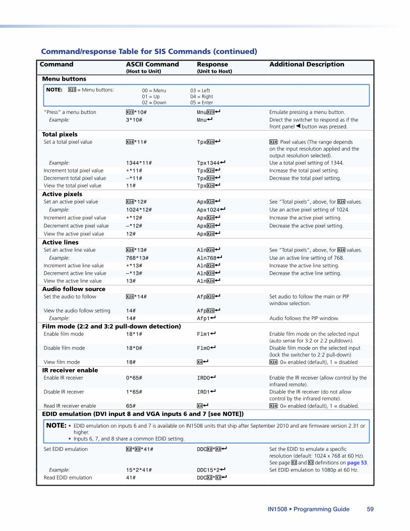
Command/response Table for SIS Commands (continued)
Command ASCII Command (Host to Unit)
Response (Unit to Host)
Additional Description
Menu buttons
NOTE: X2# = Menu buttons: 00 = Menu 03 = Left 01 = Up 04 = Right 02 = Down 05 = Enter
“Press” a menu button X2#*10# MnuX2#] Emulate pressing a menu button.Example: 3*10# Mnu] Direct the switcher to respond as if the
front panel button was pressed.
Total pixelsSet a total pixel value X2$*11# TpxX2$] X2$: Pixel values (The range depends
on the input resolution applied and the output resolution selected).
Example: 1344*11# Tpx1344] Use a total pixel setting of 1344.Increment total pixel value +*11# TpxX2$] Increase the total pixel setting.Decrement total pixel value –*11# TpxX2$] Decrease the total pixel setting.View the total pixel value 11# TpxX2$]
Active pixelsSet an active pixel value X2$*12# ApxX2$] See “Total pixels”, above, for X2$ values.
Example: 1024*12# Apx1024] Use an active pixel setting of 1024.
Increment active pixel value +*12# ApxX2$] Increase the active pixel setting.
Decrement active pixel value –*12# ApxX2$] Decrease the active pixel setting.
View the active pixel value 12# ApxX2$]
Active linesSet an active line value X2$*13# AlnX2$] See “Total pixels”, above, for X2$ values.
Example: 768*13# Aln768] Use an active line setting of 768.Increment active line value +*13# AlnX2$] Increase the active line setting.Decrement active line value –*13# AlnX2$] Decrease the active line setting.View the active line value 13# AlnX2$]
Audio follow sourceSet the audio to follow X2%*14# AfpX2%] Set audio to follow the main or PIP
window selection.View the audio follow setting 14# AfpX2%]
Example: 14# Afp1] Audio follows the PIP window.
Film mode (2:2 and 3:2 pull-down detection)Enable film mode 18*1# Flm1] Enable film mode on the selected input
(auto sense for 3:2 or 2:2 pulldown).Disable film mode 18*0# Flm0] Disable film mode on the selected input
(lock the switcher to 2:2 pull-down)View film mode 18# X$] X2$: 0= enabled (default), 1 = disabled
IR receiver enableEnable IR receiver 0*65# IRD0] Enable the IR receiver (allow control by the
infrared remote).Disable IR receiver 1*65# IRD1] Disable the IR receiver (do not allow
control by the infrared remote).Read IR receiver enable 65# X$] X2$: 0= enabled (default), 1 = disabled.
EDID emulation (DVI input 8 and VGA inputs 6 and 7 [see NOTE])
NOTE: • EDID emulation on inputs 6 and 7 is available on IN1508 units that ship after September 2010 and are firmware version 2.31 or higher.
• Inputs 6, 7, and 8 share a common EDID setting.
Set EDID emulation X@*X#*41# DDCX@*X#] Set the EDID to emulate a specific resolution (default: 1024 x 768 at 60 Hz). See page X@ and X# definitions on page 53.
Example: 15*2*41# DDC15*2] Set EDID emulation to 1080p at 60 Hz.Read EDID emulation 41# DDCX@*X#]
IN1508 • Programming Guide 59
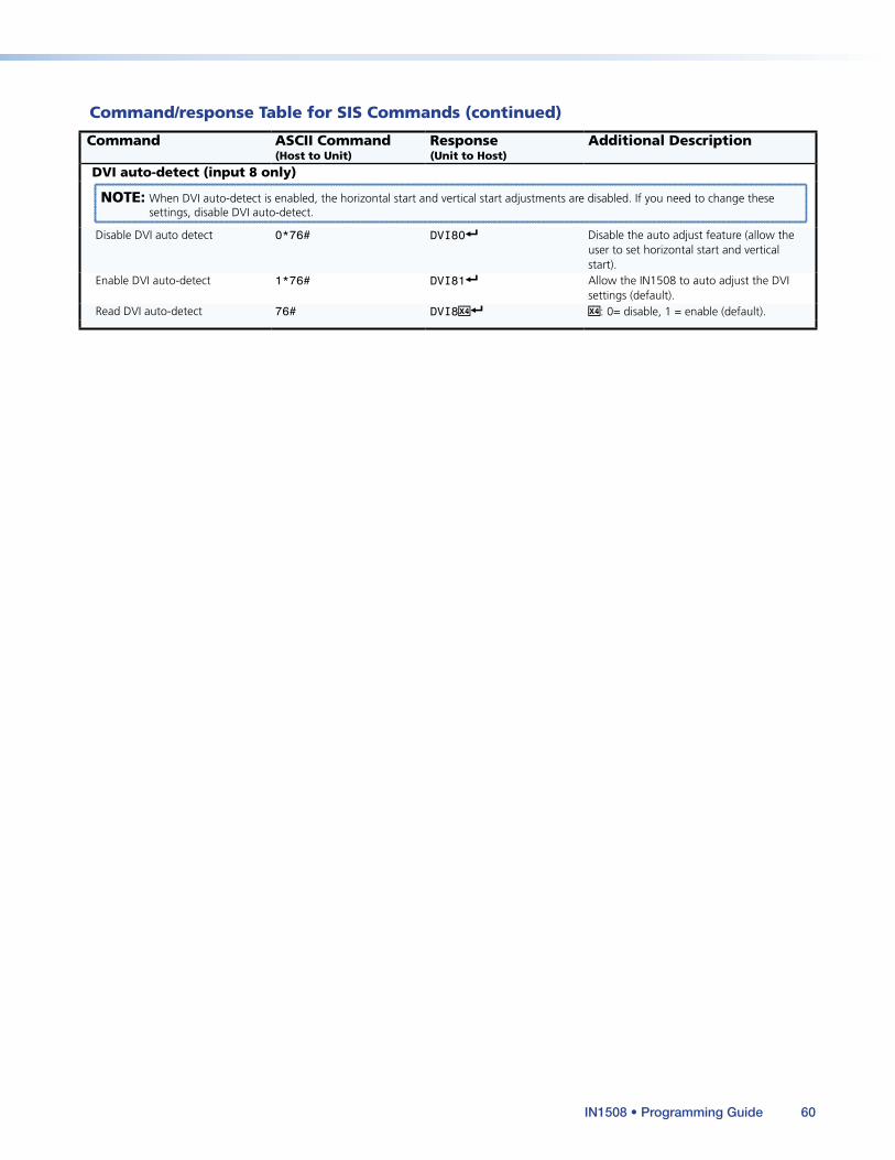
Command/response Table for SIS Commands (continued)
Command ASCII Command (Host to Unit)
Response (Unit to Host)
Additional Description
DVI auto-detect (input 8 only)
NOTE: When DVI auto-detect is enabled, the horizontal start and vertical start adjustments are disabled. If you need to change these settings, disable DVI auto-detect.
Disable DVI auto detect 0*76# DVI80] Disable the auto adjust feature (allow the user to set horizontal start and vertical start).
Enable DVI auto-detect 1*76# DVI81] Allow the IN1508 to auto adjust the DVI settings (default).
Read DVI auto-detect 76# DVI8X$] X$: 0= disable, 1 = enable (default).
IN1508 • Programming Guide 60
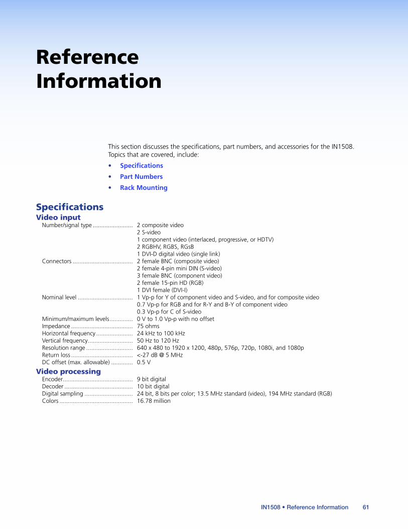
Reference Information
This section discusses the specifications, part numbers, and accessories for the IN1508. Topics that are covered, include:
• Specifications
• Part Numbers
• Rack Mounting
SpecificationsVideo input
Number/signal type ........................ 2 composite video 2 S-video 1 component video (interlaced, progressive, or HDTV) 2 RGBHV, RGBS, RGsB 1 DVI-D digital video (single link)
Connectors .................................... 2 female BNC (composite video) 2 female 4-pin mini DIN (S-video) 3 female BNC (component video) 2 female 15-pin HD (RGB) 1 DVI female (DVI-I)
Nominal level ................................. 1 Vp-p for Y of component video and S-video, and for composite video 0.7 Vp-p for RGB and for R-Y and B-Y of component video 0.3 Vp-p for C of S-video
Minimum/maximum levels .............. 0 V to 1.0 Vp-p with no offsetImpedance ..................................... 75 ohmsHorizontal frequency ...................... 24 kHz to 100 kHzVertical frequency ........................... 50 Hz to 120 HzResolution range ............................ 640 x 480 to 1920 x 1200, 480p, 576p, 720p, 1080i, and 1080pReturn loss ..................................... <-27 dB @ 5 MHzDC offset (max. allowable) ............. 0.5 V
Video processingEncoder .......................................... 9 bit digitalDecoder ......................................... 10 bit digitalDigital sampling ............................. 24 bit, 8 bits per color; 13.5 MHz standard (video), 194 MHz standard (RGB)Colors ............................................ 16.78 million
61IN1508 • Reference Information

Video outputNumber/signal type ........................ Scaled RGBHV, RGBS, RGsB; Y, R-Y, B-YConnectors .................................... 1 female 15-pin HDNominal level ................................. 1 Vp-p for Y of component video and for G of RGsB
0.7 Vp-p for RGB and for R-Y and B-Y of component videoMinimum/maximum levels .............. 0 V to 1.0 Vp-pImpedance ..................................... 75 ohmsVertical frequency ........................... 24 Hz, 50 Hz, 59.94 Hz, 60 Hz, or 75 Hz, depending on selected output resolutionScaled resolution ............................ 640x4801,2,3, 800x6001,2,3, 852x4801,2, 1024x7681,2,3, 1024x8521,2,3, 1024x10241,2,3,
1280x7682, 1280x8001,2, 1280x10241,2,3, 1366x7681,2,3, 1365x10241,2,3, 1400x10501,2, 1440x9002,3, 1600x12001,2, 1680x10502, 480p2,4, 576p1, 720p1,2,4, 1080i1,2,4, 1080p1,2,3,4, 1080p Sharp2, 1920x12002, 1080p CVT2 1 = at 50 Hz, 2 = at 60 Hz, 3 = at 75 Hz (24 Hz for 1080p); 4 = 59.94 Hz
Return loss ..................................... -21 dB @ 5 MHzDC offset ....................................... ±300 mV maximum with input at 0 offset
SyncInput type ...................................... RGBHV, RGBS, RGsB, bi-level or tri-level component videoOutput type ................................... RGBHV, RGBS, RGsB; Y, R-Y, B-Y (tri-level)Standards ....................................... NTSC 3.58, NTSC 4.43, PAL, SECAMInput level ...................................... 2.75 V to 5.0 Vp-p for RGBHV or RGBS
0.6 Vp-p for component video tri-level sync 0.3 Vp-p for component video bi-level sync or RGsB
Output level ................................... TTL: 5.0 Vp-p, unterminatedInput impedance ............................ 1k ohmsOutput impedance ......................... 45 ohmsMax. input voltage ......................... 5V p-pPolarity ........................................... Positive or negative (selectable)
AudioGain ............................................... Unbalanced output: 0 dB; balanced output: +6 dBFrequency response ........................ 20 Hz to 20 kHz, ±1.7 dBTHD + Noise ................................... 0.03% @ 1 kHz at nominal level, 0 dB gainS/N ................................................. >90 dB at rated maximum outputCrosstalk ........................................ <-70 dB @ 1 kHzStereo channel separation .............. >84 dB @ 1 kHz
Audio inputNumber/signal type ........................ 8 stereo, unbalancedConnectors .................................... 5 pairs of RCA (tip-ring) jacks
(3) 3.5 mm mini stereo (tip-ring-sleeve) jacksImpedance ..................................... >10k ohms unbalanced, DC coupledNominal level ................................. +4 dBu (1.23 Vrms), -10 dBV (316 mVrms)Maximum level ............................... +10.4 dBu, (unbalanced) at 1% THD+NInput gain adjustment .................... -65 dBu to +9 dBu, adjustable per input
NOTE: 0 dBu = 0.775 Vrms, 0 dBV = 1 Vrms, 0 dBV ≈ 2 dBu
Audio outputNumber/signal type ........................ 1 stereo, unbalanced
1 stereo, balanced/unbalancedConnectors .................................... 1 pair of RCA (tip-ring) jacks
(1) 3.5 mm captive screw connector, 5 poleImpedance ..................................... 50 ohms unbalanced, 100 ohms balancedGain error ...................................... ±0.1 dB channel to channelMaximum level (Hi-Z) ...................... >+16 dBu, balanced at 1% THD+N
>+10 dBu, unbalanced at 1% THD+NMaximum level (600 ohm) .............. >+10 dBu, balanced at 1% THD+N
>+7 dBu, unbalanced at 1% THD+N
IN1508 • Reference Information 62
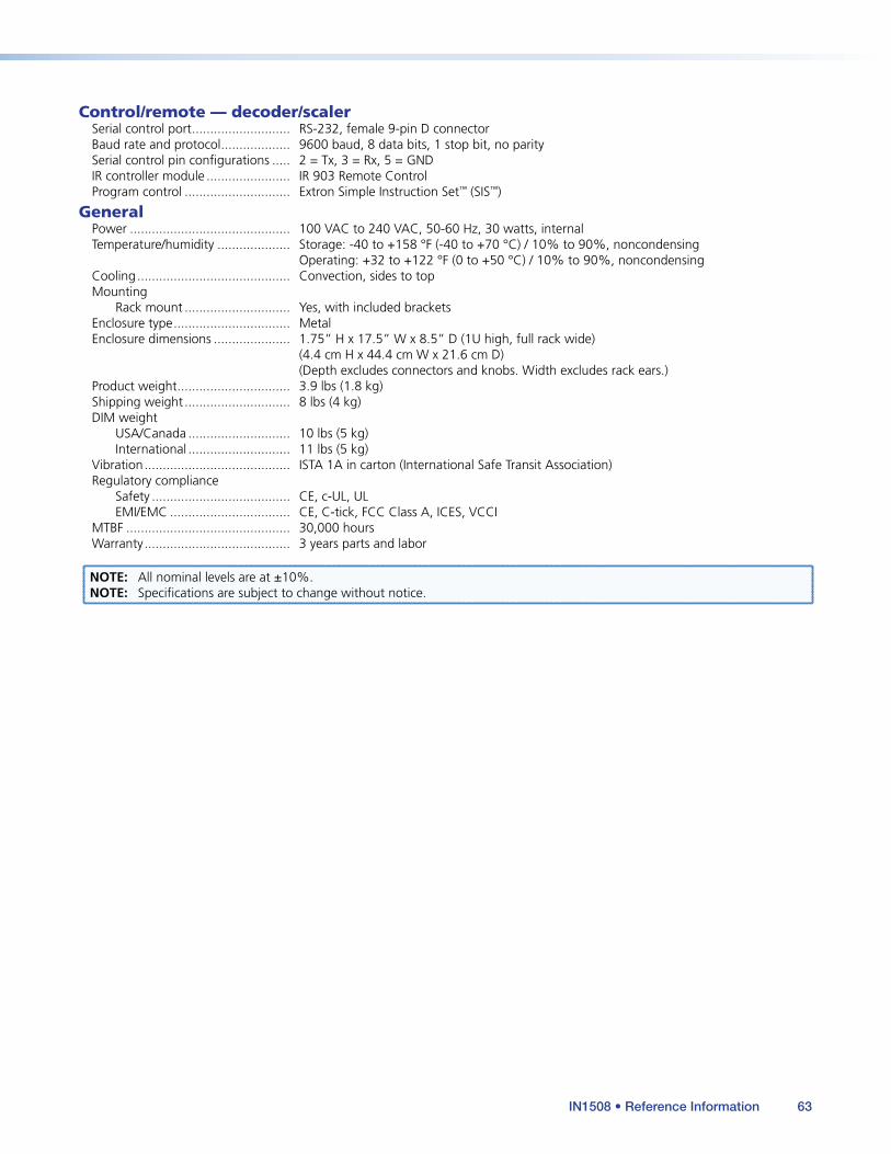
Control/remote — decoder/scalerSerial control port ........................... RS-232, female 9-pin D connectorBaud rate and protocol ................... 9600 baud, 8 data bits, 1 stop bit, no paritySerial control pin configurations ..... 2 = Tx, 3 = Rx, 5 = GNDIR controller module ....................... IR 903 Remote ControlProgram control ............................. Extron Simple Instruction Set™ (SIS™)
GeneralPower ............................................ 100 VAC to 240 VAC, 50-60 Hz, 30 watts, internalTemperature/humidity .................... Storage: -40 to +158 °F (-40 to +70 °C) / 10% to 90%, noncondensing
Operating: +32 to +122 °F (0 to +50 °C) / 10% to 90%, noncondensingCooling .......................................... Convection, sides to topMounting
Rack mount ............................. Yes, with included bracketsEnclosure type ................................ MetalEnclosure dimensions ..................... 1.75” H x 17.5” W x 8.5” D (1U high, full rack wide)
(4.4 cm H x 44.4 cm W x 21.6 cm D) (Depth excludes connectors and knobs. Width excludes rack ears.)
Product weight ............................... 3.9 lbs (1.8 kg)Shipping weight ............................. 8 lbs (4 kg)DIM weight
USA/Canada ............................ 10 lbs (5 kg)International ............................ 11 lbs (5 kg)
Vibration ........................................ ISTA 1A in carton (International Safe Transit Association)Regulatory compliance
Safety ...................................... CE, c-UL, ULEMI/EMC ................................. CE, C-tick, FCC Class A, ICES, VCCI
MTBF ............................................. 30,000 hoursWarranty ........................................ 3 years parts and labor
NOTE: All nominal levels are at ±10%.NOTE: Specifications are subject to change without notice.
IN1508 • Reference Information 63
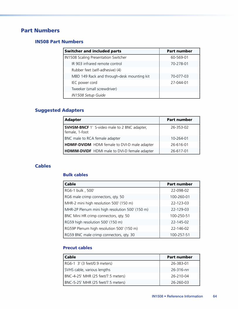
Part Numbers
IN508 Part Numbers
Switcher and included parts Part number
IN1508 Scaling Presentation Switcher 60-569-01
IR 903 infrared remote control 70-278-01
Rubber feet (self-adhesive) (4)
MBD 149 Rack and through-desk mounting kit 70-077-03
IEC power cord 27-044-01
Tweeker (small screwdriver)
IN1508 Setup Guide
Suggested Adapters
Adapter Part number
SVHSM-BNCF 1' S-video male to 2 BNC adapter, female, 1-foot
26-353-02
BNC male to RCA female adapter 10-264-01
HDMIF-DVIDM HDMI female to DVI-D male adapter 26-616-01
HDMIM-DVIDF HDMI male to DVI-D female adapter 26-617-01
Cables
Bulk cables
Cable Part number
RG6-1 bulk , 500' 22-098-02
RG6 male crimp connectors, qty. 50 100-260-01
MHR-2 mini high resolution 500' (150 m) 22-123-03
MHR-2P Plenum mini high resolution 500' (150 m) 22-129-03
BNC Mini HR crimp connectors, qty. 50 100-250-51
RG59 high resolution 500' (150 m) 22-145-02
RG59P Plenum high resolution 500' (150 m) 22-146-02
RG59 BNC male crimp connectors, qty. 30 100-257-51
Precut cables
Cable Part number
RG6-1 3' (3 feet/0.9 meters) 26-383-01
SVHS cable, various lengths 26-316-nn
BNC-4-25' MHR (25 feet/7.5 meters) 26-210-04
BNC-5-25' MHR (25 feet/7.5 meters) 26-260-03
IN1508 • Reference Information 64
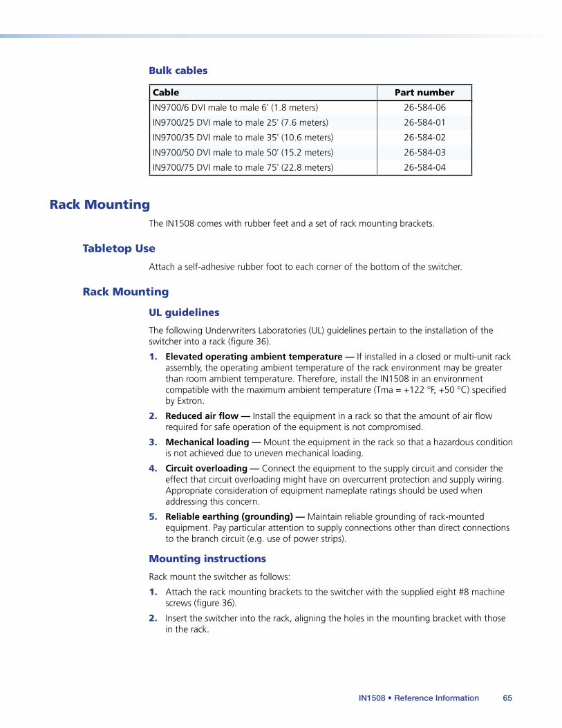
Bulk cables
Cable Part number
IN9700/6 DVI male to male 6' (1.8 meters) 26-584-06
IN9700/25 DVI male to male 25' (7.6 meters) 26-584-01
IN9700/35 DVI male to male 35' (10.6 meters) 26-584-02
IN9700/50 DVI male to male 50' (15.2 meters) 26-584-03
IN9700/75 DVI male to male 75' (22.8 meters) 26-584-04
Rack MountingThe IN1508 comes with rubber feet and a set of rack mounting brackets.
Tabletop Use
Attach a self-adhesive rubber foot to each corner of the bottom of the switcher.
Rack Mounting
UL guidelines
The following Underwriters Laboratories (UL) guidelines pertain to the installation of the switcher into a rack (figure 36).
1. Elevated operating ambient temperature — If installed in a closed or multi-unit rack assembly, the operating ambient temperature of the rack environment may be greater than room ambient temperature. Therefore, install the IN1508 in an environment compatible with the maximum ambient temperature (Tma = +122 °F, +50 °C) specified by Extron.
2. Reduced air flow — Install the equipment in a rack so that the amount of air flow required for safe operation of the equipment is not compromised.
3. Mechanical loading — Mount the equipment in the rack so that a hazardous condition is not achieved due to uneven mechanical loading.
4. Circuit overloading — Connect the equipment to the supply circuit and consider the effect that circuit overloading might have on overcurrent protection and supply wiring. Appropriate consideration of equipment nameplate ratings should be used when addressing this concern.
5. Reliable earthing (grounding) — Maintain reliable grounding of rack-mounted equipment. Pay particular attention to supply connections other than direct connections to the branch circuit (e.g. use of power strips).
Mounting instructions
Rack mount the switcher as follows:
1. Attach the rack mounting brackets to the switcher with the supplied eight #8 machine screws (figure 36).
2. Insert the switcher into the rack, aligning the holes in the mounting bracket with those in the rack.
IN1508 • Reference Information 65

100-240V 50-60Hz I
N
P
U
T
VID
VID
YC
Y
B-Y
C-Y
RGB
DVI
1
2
4
5
3
L
2
3
4
5
6
7
R
AUDIO INPUT
L
A
B
R
OUTPUT
L
R
OUTPUT
RGB
Y, B-Y, C
-Y
8
7
RGB
6
LISTED
1T23
I.T.E.
C
U S
Rack-mountBracket
Figure 36. Mounting the Switcher
3. Secure the switcher to the rack using the supplied machine screws.
IN1508 • Reference Information 66

Extron® WarrantyExtron Electronics warrants this product against defects in materials and workmanship for a period of three years from the date of purchase. In the event of malfunction during the warranty period attributable directly to faulty workmanship and/or materials, Extron Electronics will, at its option, repair or replace said products or components, to whatever extent it shall deem necessary to restore said product to proper operating condition, provided that it is returned within the warranty period, with proof of purchase and description of malfunction to:
USA, Canada, South America, and Central America: Extron Electronics 1001 East Ball Road Anaheim, CA 92805 U.S.A.
Japan: Extron Electronics, Japan Kyodo Building, 16 Ichibancho Chiyoda-ku, Tokyo 102-0082 Japan
Europe, Africa, and the Middle East: Extron Europe Hanzeboulevard 10 3825 PH Amersfoort The Netherlands
China: Extron China 686 Ronghua Road Songjiang District Shanghai 201611 China
Asia: Extron Asia 135 Joo Seng Road, #04-01 PM Industrial Bldg. Singapore 368363 Singapore
Middle East: Extron Middle East Dubai Airport Free Zone F12, PO Box 293666 United Arab Emirates, Dubai
This Limited Warranty does not apply if the fault has been caused by misuse, improper handling care, electrical or mechanical abuse, abnormal operating conditions, or if modifications were made to the product that were not authorized by Extron.
NOTE: If a product is defective, please call Extron and ask for an Application Engineer to receive an RA (Return Authorization) number. This will begin the repair process. USA: (714) 491-1500 Europe: +31.33.453.4040 Asia: +65.6383.4400 Japan: +81.3.3511.7655
Units must be returned insured, with shipping charges prepaid. If not insured, you assume the risk of loss or damage during shipment. Returned units must include the serial number and a description of the problem, as well as the name of the person to contact in case there are any questions.
Extron Electronics makes no further warranties either expressed or implied with respect to the product and its quality, performance, merchantability, or fitness for any particular use. In no event will Extron Electronics be liable for direct, indirect, or consequential damages resulting from any defect in this product even if Extron Electronics has been advised of such damage.
Please note that laws vary from state to state and country to country, and that some provisions of this warranty may not apply to you.
Extron USA - WestHeadquarters
+800.633.9876Inside USA/Canada Only
+1.714.491.1500+1.714.491.1517 FAX
Extron USA - East
+800.633.9876Inside USA/Canada Only
+1.919.863.1794+1.919.863.1797 FAX
Extron Europe
+800.3987.6673Inside Europe Only
+31.33.453.4040+31.33.453.4050 FAX
Extron Asia
+800.7339.8766Inside Asia Only
+65.6383.4400+65.6383.4664 FAX
Extron Japan
+81.3.3511.7655+81.3.3511.7656 FAX
Extron China
+400.883.1568Inside China Only
+86.21.3760.1568+86.21.3760.1566 FAX
Extron Middle East
+971.4.2991800+971.4.2991880 FAX
© 2010 Extron Electronics. All rights reserved. www.extron.com