Embed Size (px)
Citation preview

© Copyright 2011, SOC Robotics, Inc Manual Revision 1.00
IMU8420 9/10 Degree of Freedom Extended Kalman Filter Processing Platform
+-16G, +-2000 dps, +-8Gauss, 350-1100hPa
IMU8420-9 IMU8420-10
Technical Reference Guide Preliminary PCB Rev 1.0
www.soc-robotics.com
IMU8420 Technical Reference Manual
© Copyright 2013, SOC Robotics, Inc - 2 - Manual Revision 1.00
Warranty Statement SOC Robotics warrants that the Product delivered hereunder shall conform to the applicable SOC Robotics Data Sheet or mutually agreed upon specifications and shall be free from defects in material and workmanship under normal use and service for a period of 30 days from the applicable date of invoice. Products that are “samples”, “design verification units”, and/or “prototypes” are sold “AS IS,” “WITH ALL FAULTS,” and without a warranty. If, during such warranty period, (i) SOC Robotics is notified promptly in writing upon discovery of any defect in the goods, including a detailed description of such defect; (ii) such goods are returned to SOC Robotics, DDP SOC Robotics facility accompanied by SOC Robotics Returned Material Authorization form; and (iii) SOC Robotics examination of such goods discloses to SOC Robotics satisfaction that such goods are defective and such defects are not caused by accident, abuse, misuse, neglect, alteration, improper installation, repair, improper testing, or use contrary to any instructions issued by SOC Robotics. SOC Robotics shall (at its sole option) either repair, replace, or credit Buyer the purchase price of such goods. No goods may be returned to SOC Robotics without SOC Robotics Returned Material Authorization form. Prior to any return of goods by Buyer pursuant to this Section, Buyer shall afford SOC Robotics the opportunity to inspect such goods at Buyer’s location, and any such goods so inspected shall not be returned to SOC Robotics without its prior written consent. SOC Robotics shall return any goods repaired or replaced under this warranty to Buyer transportation prepaid, and reimburse Buyer for the transportation charges paid by Buyer for such goods. The performance of this warranty does not extend the warranty period for any goods beyond that period applicable to the goods originally delivered.
THE FOREGOING WARRANTY CONSTITUTES SOC ROBOTICS EXCLUSIVE LIABILITY, AND THE EXCLUSIVE REMEDY OF BUYER, FOR ANY BREACH OF ANY WARRANTY OR OTHER NONCONFORMITY OF THE GOODS COVERED BY THIS AGREEMENT. THIS WARRANTY IS EXCLUSIVE, AND IN LIEU OF ALL OTHER WARRANTIES. SOC ROBOTICS MAKES NO OTHER WARRANTIES, EXPRESS, IMPLIED, OR STATUTORY, INCLUDING WITHOUT LIMITATION ANY WARRANTIES OF MERCHANTABILITY OR FITNESS FOR A PARTICULAR PURPOSE. THE SOLE AND EXCLUSIVE REMEDY FOR ANY BREACH OF THIS WARRANTY SHALL BE AS EXPRESSLY PROVIDED HEREIN.
Limitation on Liability Notwithstanding anything to the contrary contained herein, SOC Robotics shall not, under any circumstances, be liable to Buyer or any third parties for consequential, incidental, indirect, exemplary, special, or other damages. SOC Robotics total liability shall not exceed the total amount paid by Buyer or SOC Robotics hereunder. SOC Robotics shall not under any circumstances be liable for excess costs of re-procurement.
© Copyright 2013. SOC Robotics, Inc. All rights reserved. SOC Robotics, Inc. makes no warranty for the use of its products, other than those expressly contained in the Company’s standard warranty which is detailed in SOC Robotics Terms and Conditions located on the Company’s web site. The Company assumes no responsibility for any errors which may appear in this document, reserves the right to change devices or specifications detailed herein at any time without notice, and does not make any commitment to update the information contained herein. No licenses to patents or other intellectual property of SOC Robotics are granted by the Company in connection with the sale of SOC Robotics products, expressly or by implication. SOC Robotics products are not authorized for use as critical components in life support devices or systems. Pentium is a registered trademark of Intel Corporation. Windows, Windows NT and Windows XP are registered trademarks of Microsoft Corporation. Marks bearing ® and/or ™ are trademarks of SOC Robotics, Inc. Terms and product names in this document may be trademarks of others. 1935A–08/00/5M

IMU8420 Technical Reference Manual
© Copyright 2013, SOC Robotics, Inc - 3 - Manual Revision 1.00
Table of Contents Warranty Statement ………………………………………………………………………2
1.0 Introduction ………………………………………………………………………….4 2.0 Feature Summary ……………………………..……………………………...……6
2.1 Introduction………………………………………….………………………………..…..…7 2.2 Theory of Operation...……………………….……..…..……………………………..……8 2.3 Software Overview ...……………………..…….….…………….……….…………..……8 2.4 MEMs Specifications...…………………..………………………………..…………..……9
3.0 Detailed Description ………………………………………………………..……11
3.1 Introduction………………………………………….……………………………....…..…11 3.2 Processor...…………………………………….………..……………………..……..……12 3.3 Real Time Clock...……………………..………………………….……….…..……..……12 3.4 External microSD….....…………………..………………………………..…..………..…12 3.5 USB Port...……………………………………………………………………..….…..……12 3.6 TWI Port...……………………………………………………………………..….…..……12 3.7 Expansion Ports...……………………………..……………………………..……………13 3.8 MEMs Sensors...………………………..………..……………………………….….……13 3.9 Power Options...………………………………..……………………………….….……...13 3.10 Programming...……...………….……………………………………………..…....……13 3.11 Molex Connector……………………………………………………………………....…15 3.12 Applications……………………………………………………………………………….16
4.0 IMU8420 Hardware Expansion Ports Summary …………….….……..19 4.1 Introduction…………………………………………………………………….…….…..…20 4.2 Expansion Port J1……....……………………….…………………….…………….….…20 4.3 Expansion Port J2 ……..…...……..………………………………………………………20 4.4 Expansion Port J3.…………..……………………………………….………….…..….…20 4.5 TWI I2C Expansion Port .……………..……………………………………………..……21 4.6 Board Power Options………………………...……………………………………………22 4.7 aWire Emulation Port………………………………….…………………..………………23 4.8 JTAG Emulation Port………………………………….…………………..………………23 4.9 ANT ZigBee Wireless Communications Port ….……………………………….………23
5.0 Electrical and Mechanical Description …………………………..….……25
5.1 Component Layout…………………………………………………………………...……25 5.2 Electrical Specifications……………………………………………………………...……25 5.3 Mechanical Dimensions ……………………………………………….…………….……25
6.0 Circuit Schematics ………………………………………………………….……26

IMU8420 Technical Reference Manual
© Copyright 2013, SOC Robotics, Inc - 4 - Manual Revision 1.00
1.0 Introduction
Features: • 32bit RISC AVR32 Processor (AT32UC3C2512c)
• 64MHz frequency crystal controlled
• Hardware FPU on chip • 10DOF 4 MEMs Sensors integrated onto one PCB
• 3-Axis Accelerometer +-16G
• 3-Axis Rate Gyro 250/500/2000 deg/sec
• 3-Axis Magnetometer eight ranges from 0.88 – 8.1 gauss
• BMP180 Barometer with 8m accuracy and 0.8m sensitivity
• MS5611 Barometer with 10cm resolution
• Extended Kalman Filter real time operation (300Hz)
• All digital sensors – no analog interface required
• 8ch 12 bit A/D 1.5msample/sec
• 15 Digital IO
• SPI Port
• TWI I2C Port
• 512K Internal Program Flash
• 64K SRAM
• USB 2.0 Interface
• Up to 32Gbyte microSD Port
• ANT/ZigBee wireless port
• DFU UC3 Bootloader for reflashing
• Lithium Polymer battery charger integrated on board
• Separate 12-24V High Voltage Regulator
• 32.756KHz External Clock crystal
• Datalogging application source code for AVR Studio 6 • 3-3.3V DC operation
• Small form factor (1.34x2.34in) – 0.34in height with battery
• 9 DOF version available
• Turnkey IMU Data Logger Application V0.98 (AVR Studio 6.0 – source code included)
• IMULINK Wireless Communications Application (Java based)
• Desktop Integration with SOC Hexapod Simulator
Hardware The IMU8420 is an extremely compact embedded processing platform for 10DOF MEMs data logging and processing applications in mobile data acquisition, control and remote monitoring applications. The 32bit AVR32 processor with hardware floating-point capability is able to acquire all the MEMs sensor data and convert it to roll, pitch and yaw using an Extended Kalman Filter in real time (300Hz). The AT32UC3C2512 runs at 64Mhz and has extensive peripherals for fast real time data acquisition and processing. An external 32.756KHz clock crystal is also on the board to provide an accurate real time clock active during power down modes. The IMU8420 consumes about 35ma in the active state (not including losses through the USB voltage regulator - not present with battery operation) and about 1.5ma in standby. By changing the internal clock and reducing power to certain peripherals it is possible for the IMU8420 to operate with very low power consumption. The IMU8420 is programming using an the on chip DFU programmer via the USB port so no external programmer is required to re-flash the part.

IMU8420 Technical Reference Manual
© Copyright 2013, SOC Robotics, Inc - 5 - Manual Revision 1.00
The Rev 1.0 PCB has connectors J1, J2 and J3 on 0.1” pin spacing so prototype daughter cards can easily be attached to the top or bottom of the board making custom circuit design possible without the need for a custom PCB. The IMU8420 can be power via the USB port, lithium polymer battery, 12-24VDC in using the optional High Voltage Regulator or by two double AA batteries (with the optional battery holder installed) with power source selected by a slide switch.
Software The IMU8420 IMU Data Logger V0.98 application was developed using Atmel’s AVR Studio 6.0 IDE. An on chip DFU bootloader allows new versions to be loaded without the need for any external programming hardware. The complete Project Folder is available for download on the SOC Robotics web site. A brief description of the IMU Data Logger command options is in Section 3.12.
Configurations The IMU8420 is available in two different configurations – a 9DOF or 10DOF. The difference between the two is the installation of a barometric pressure sensor.
MEMs Configuration
Model Designation
9 DOF IMU8420-9 10 DOF IMU8420-10
Options The following options are available for the IMU8420: High performance barometer MS5611 High Voltage Regulator Lithium Polymer Battery 145mah, 230mah and 240mah AA Battery Holder New Data Logger Version 1.00 Features The IMU8420 comes pre-loaded with a comprehensive IMU Data Logger and EKF sensor fusion algorithm. The current version is V0.98. The next release of the IMU Data Logger will provide extensive support for both ANT and ZigBee wireless operation. The V1.00 release will come with a new Java desktop application IMULINK for real time data logging, data retrieval and control. V1.00 is scheduled for mid February 2013 release.
IMU8420 Technical Reference Manual
© Copyright 2013, SOC Robotics, Inc - 6 - Manual Revision 1.00
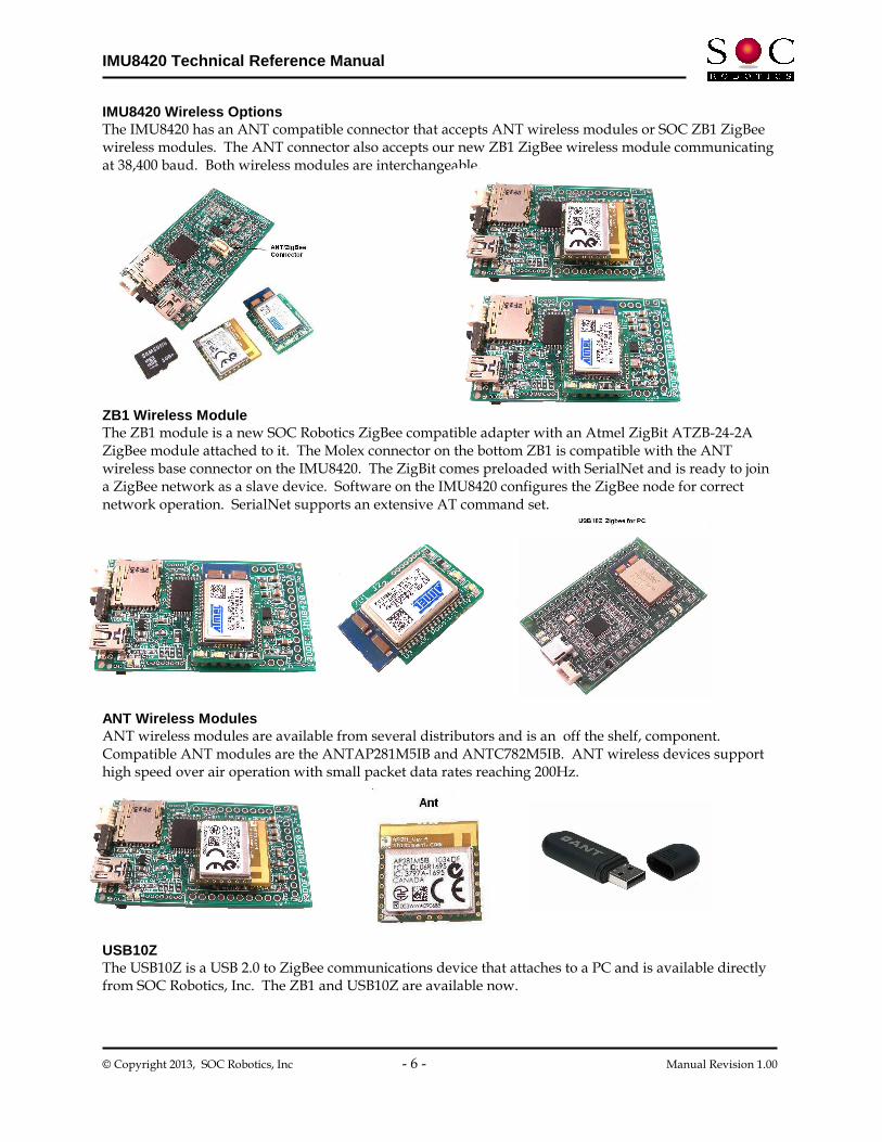
IMU8420 Wireless Options The IMU8420 has an ANT compatible connector that accepts ANT wireless modules or SOC ZB1 ZigBee wireless modules. The ANT connector also accepts our new ZB1 ZigBee wireless module communicating at 38,400 baud. Both wireless modules are interchangeable. ZB1 Wireless Module The ZB1 module is a new SOC Robotics ZigBee compatible adapter with an Atmel ZigBit ATZB-24-2A ZigBee module attached to it. The Molex connector on the bottom ZB1 is compatible with the ANT wireless base connector on the IMU8420. The ZigBit comes preloaded with SerialNet and is ready to join a ZigBee network as a slave device. Software on the IMU8420 configures the ZigBee node for correct network operation. SerialNet supports an extensive AT command set. ANT Wireless Modules ANT wireless modules are available from several distributors and is an off the shelf, component. Compatible ANT modules are the ANTAP281M5IB and ANTC782M5IB. ANT wireless devices support high speed over air operation with small packet data rates reaching 200Hz. USB10Z The USB10Z is a USB 2.0 to ZigBee communications device that attaches to a PC and is available directly from SOC Robotics, Inc. The ZB1 and USB10Z are available now.

IMU8420 Technical Reference Manual
© Copyright 2013, SOC Robotics, Inc - 7 - Manual Revision 1.00
2.0 Feature Summary
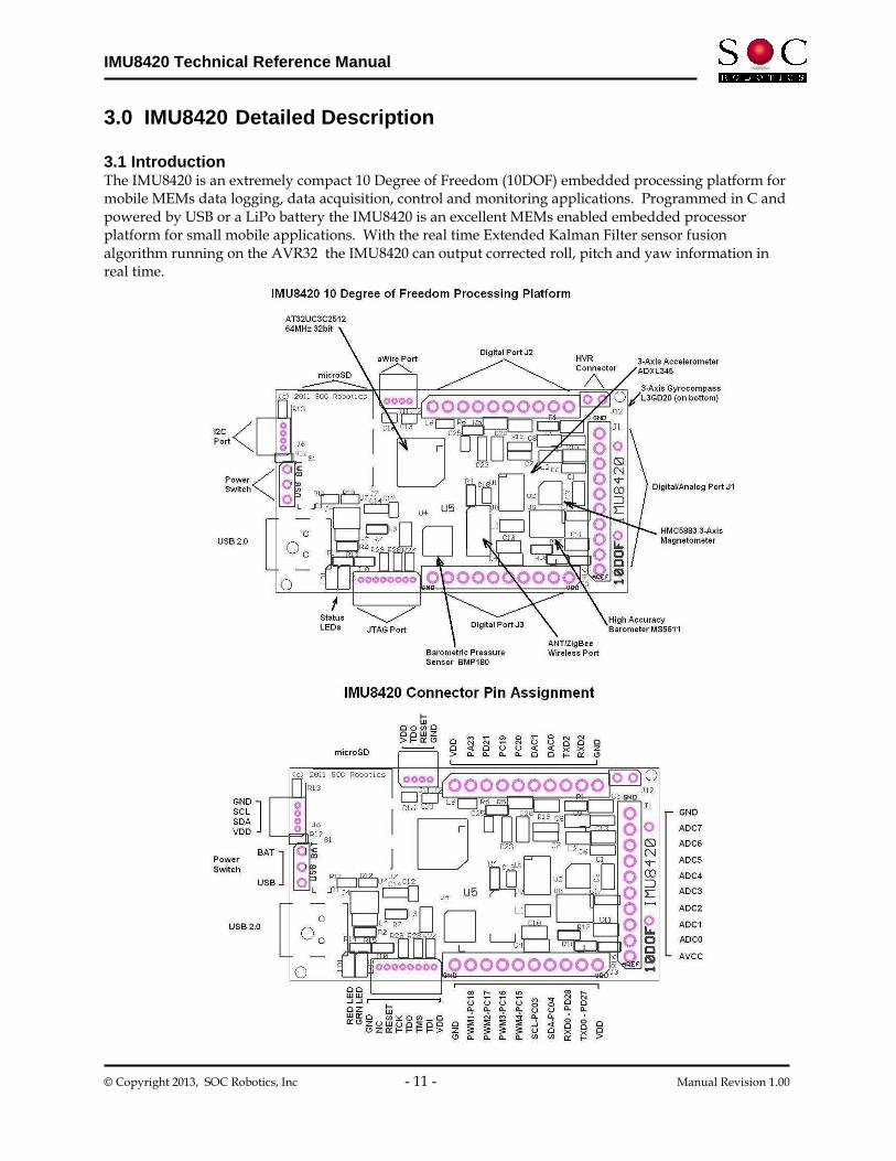
2.1 Introduction The IMU8420 is a 10 Degree of Freedom (DOF) all digital sensor that brings a new level of integration and sensing. The IMU8420 has a 3-axis accelerometer, 3-axis rate gyro, 3-axis magnetometer and a barometric pressure sensor. The accelerometer is the Analog Devices ADXL345 with several acceleration range settings with a maximum of +-16G and a sensitivity of 4mG. The rate gyro is the ST Microelectronics L3G20D with three range settings of 250, 500 and 2000 deg/sec. The magnetometer is a Honeywell HMC5883 with eight range settings from 0.88Gauss to 8.1Gauss. The barometer is a Bosch BMP085 with an absolute accuracy of 8M and a sensitivity of 80cm. The picture below shows the IMU8420 pin assignment. The accelerometer and rate gyro use an SPI interface while the magnetometer and barometer are I2C devices. Software to program and configure each of the four sensors is provided. The IMU8420 has three expansion ports with a mix of digital IO and analog IO.

IMU8420 Technical Reference Manual
© Copyright 2013, SOC Robotics, Inc - 8 - Manual Revision 1.00
2.2 Theory of Operation Circuit Description The IMU8420 uses sensors with digital interfaces so no A/D conversion interface logic is required. See the individual sensor datasheets for detailed operational and programming information. The Accelerometer and Rate Gyro have a high speed SPI interface. The Magnetometer and Barometric pressure sensor have an I2C interface. The IMU8420 is easily interfaced to other processors via the I2C and multiple UART interfaces. The output from each sensor is in binary format and is easily converted to engineering units. The pressure sensor, however, requires a more sophisticated conversion formula and the source code for this conversion is provided in the sample application IMU Data Logger V0.98 available for download from our web site.
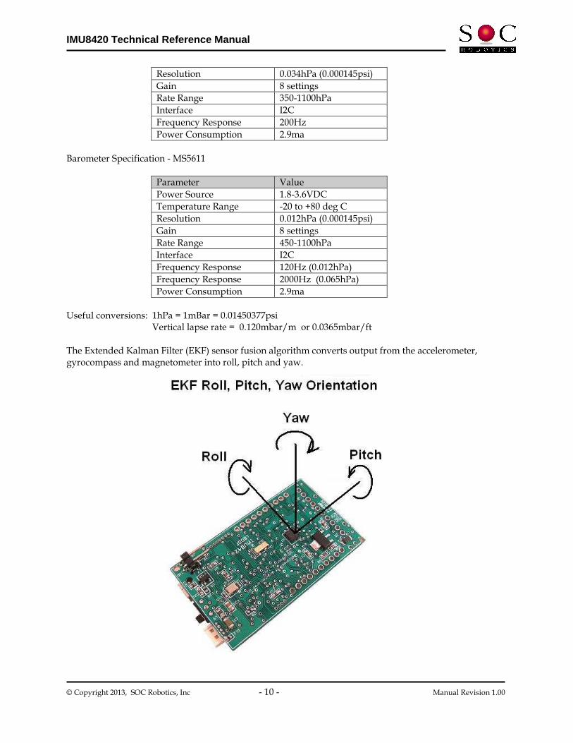
Polarity of Measurement The IMU8420 outputs sensor data with 9 degrees of freedom. The pictures below show the output orientation of each sensor. The barometric pressure sensor is not affected by orientation. Calibration Although each sensor has a digital interface sensor output may vary slightly due to sensor mounting skew – this should be taken into account before use.
2.3 Software Overview A sample application running on the AVR32 called the IMU Data Logger V0.98 configures each of the sensors on the IMU8420 and outputs the sensor data to the USB port. The application was developed using Atmel’s AVR Studio 6 IDE and the project file (with full source code) can be downloaded from the SOC Robotics web site. The IMU Data Logger is a complete data logging application designed to simplify the setup and configuration of the sensors. Included is a sophisticated Extended Kalman Filter sensor fusion algorithm along with various MEMs sensor test and configuration functions. Users can easily modify the source code to add additional functions such as AHRS or additional processing tasks. The Data Logger application requires approximately a third of the 512K flash leaving plenty of room for custom enhancements.

IMU8420 Technical Reference Manual
© Copyright 2013, SOC Robotics, Inc - 9 - Manual Revision 1.00
A Java desktop GUI application IMULINK is in development and will be released in Q1 2013.
2.4 MEMs Specifications The IMU8420 uses the STMicroelectronics L3GD20D digital 3-axis rate gyro, the Analog Devices ADXL345 3-axis accelerometer, Honeywell HMC5883 3-axis magnetometer and the Bosch BMP180 or Measurement Specialties MS5611 barometric pressure sensor. Several of the sensors also include an on chip temperature sensor. Accelerometer Specifications – ADXL345
Parameter Value
Power Source 3.0V-+0.3VDC
Temperature Range -20 to +80 deg C
Resolution 4mG
Gain 2,4,8,16g
Rate Range -+100 deg/sec
Interface SPI
Frequency Response 1600Hz
Power Consumption 140uA
Rate Gyro Specifications – L3GD20
Parameter Value
Power Source 3.0V-+0.6VDC
Temperature Range -20 to +80 deg C
Resolution 8.7/17/70mdps
Gain 3 settings
Rate Range 250/500/2000dps
Interface SPI
Frequency Response 760Hz (90 deg delay)
Power Consumption 2.9ma
Magnetometer Specifications – HMC5883
Parameter Value
Power Source 3.0V-+0.3VDC
Temperature Range -20 to +80 deg C
Resolution 5mGauss
Gain 8 settings
Rate Range 0.88,1.3,8.1Gauss
Interface I2C
Frequency Response 200Hz
Power Consumption 2.9ma
Barometer Specification - BMP180
Parameter Value
Power Source 1.8-3.6VDC
Temperature Range -20 to +80 deg C
IMU8420 Technical Reference Manual
© Copyright 2013, SOC Robotics, Inc - 10 - Manual Revision 1.00
Resolution 0.034hPa (0.000145psi)
Gain 8 settings
Rate Range 350-1100hPa
Interface I2C
Frequency Response 200Hz
Power Consumption 2.9ma
Barometer Specification - MS5611
Parameter Value
Power Source 1.8-3.6VDC
Temperature Range -20 to +80 deg C
Resolution 0.012hPa (0.000145psi)
Gain 8 settings
Rate Range 450-1100hPa
Interface I2C
Frequency Response 120Hz (0.012hPa)
Frequency Response 2000Hz (0.065hPa)
Power Consumption 2.9ma
Useful conversions: 1hPa = 1mBar = 0.01450377psi Vertical lapse rate = 0.120mbar/m or 0.0365mbar/ft The Extended Kalman Filter (EKF) sensor fusion algorithm converts output from the accelerometer, gyrocompass and magnetometer into roll, pitch and yaw.
IMU8420 Technical Reference Manual
© Copyright 2013, SOC Robotics, Inc - 11 - Manual Revision 1.00
3.0 IMU8420 Detailed Description 3.1 Introduction The IMU8420 is an extremely compact 10 Degree of Freedom (10DOF) embedded processing platform for mobile MEMs data logging, data acquisition, control and monitoring applications. Programmed in C and powered by USB or a LiPo battery the IMU8420 is an excellent MEMs enabled embedded processor platform for small mobile applications. With the real time Extended Kalman Filter sensor fusion algorithm running on the AVR32 the IMU8420 can output corrected roll, pitch and yaw information in real time.

IMU8420 Technical Reference Manual
© Copyright 2013, SOC Robotics, Inc - 12 - Manual Revision 1.00
3.2 Processor The IMU8420 uses a 32bit RISC AVR32 AT32UC3C2512 processor running at 64MHz. The processor has a large number of internal peripherals, a hardware Floating Point Unit, event system and DMA driven cross point switch. The Processor is capable of significant processing throughput and is able to run a complex Extended Kalman Filter sensor fusion algorithm at a 300Hz rate. A detailed device datasheet is available from the Atmel’s web site providing detailed information on the internal peripherals. The AT32UC3C2512 is clock by an external 16MHz crystal and the board runs at 3.30V when powered by the USB port, Lithium Polymer battery and High Voltage Regulator and 3.00 volts when powered by two AA batteries. Nominal power consumption of the board is 34ma. If internal peripherals are turned off and the processor placed in a sleep state power drops below 1ma. 3.3 Real Time Clock A 32.756KHz clock crystal is connected to the AVR32’s internal real time clock. The 32bit real time counter is used to time stamp MEMs sensor data. The real time clock can be configured to wake the processor from a sleep state reducing power consumption dramatically. 3.4 microSD Port The IMU8420 has a microSD connector that supports microSD storage cards with FAT16/FAT32 file support. Up to 32G cards can be used. 3.5 USB 2.0 Port The IMU8420 has a USB 2.0 port configured as a serial communication device CDC COMx. Baud rates up to 2Mbits/second are supported. The USB interface on the AT32UC3C2512 can be configured as 3.6 TWI Port The IMU8420 has a TWI I2C port for communicating with smart peripherals, off board sensors and/or other I2C peripherals. The TWI port uses a 4 pin Molex connector with power and ground so the IMU8420 can power other peripherals or be powered itself via this connector.
Figure 2-1. Feature summary and expansion ports pin assignments.

IMU8420 Technical Reference Manual
© Copyright 2013, SOC Robotics, Inc - 13 - Manual Revision 1.00
3.7 Expansion Ports The IMU8420 has three expansion ports J1, J2 and J3, an I2C port and two programming/emulation ports – aWire and JTAG. The emulation ports don’t have connectors installed, as the preferred method of reprogramming the board is to use the on chip DFU bootloader.
3.8 MEMs sensors The IMU8420 uses the STMicroelectronics L3GD20D digital 3-axis rate gyro, the Analog Devices ADXL345 3-axis accelerometer, Honeywell HMC5883 3-axis magnetometer and the Bosch BMP180 barometric pressure sensor or Measurement Specialties MS5611. Both of the barometers can be installed at the same time. See the respective vendor datasheets for detail specifications and programming information.
3.9 Power Options The IMU8420 can be powered either by the USB port, a Lithium Polymer battery or the optional 12-24VDC High Voltage Regulator (HVR). An onboard charging circuit powered by either the USB Port or HVR charges the Lithium Polymer battery. In addition, an optional battery holder can be installed on the bottom of the board that holds two AA batteries. A slide switch selects power from the USB Port or battery pack.
3.10 Programming The AT32UC3C2512 can be programmed using the on chip DFU bootloader, the aWire port or the JTAG port. The preferred method of programming is to use the DFU bootloader. Programming the AT32UC3C2512 To program the AT32UC3C2512 using the DFU bootloader follow the steps below:
- Download the AVR Studio 6.0 IDE from the Atmel web site (registration required) - Download the IMU8420 Data Logger V0.98 Project File from the SOC Robotics web site - Download the Flip programming utility from the Atmel web site - Find the debug folder in the IMU8420 Project file folder - Plug the IMU8420 into the Windows PC and load the *.inf file located in the debug folder
to install the CDC Virtual COM driver - Start a terminal app such as HyperTerminal and make sure the IMU8420 communicates with the
desktop - Connect PD21 on J2 to ground and repower the board – this should start the DFU bootloader - Windows will ask for the location of the *.inf file for the DFU bootloader – it is located is located
in the same debug folder - Run the batch file p512.bat – this starts the programming process - If any changes are made to the IMU8420 project files and build is successful repeat the last two
steps t0 load the new code – batchisp does not overwrite the bootloader even though it says it does
The contents of p512.bat is below: batchisp -device at32uc3c2512c -hardware usb -operation erase f memory flash blankcheck loadbuffer IMU8420_Controller.elf program verify start reset 0 DFU AT32UC3C2512 Bootloader The AT32UC3C2512 has an on chip DFU bootloader that is activated by pulling signal PD21 on connector J2 to ground when the board is powered up. Once the bootloader starts it requests a USB driver be

IMU8420 Technical Reference Manual
© Copyright 2013, SOC Robotics, Inc - 14 - Manual Revision 1.00
installed which is an Atmel program called batchisp.exe is used to reprogram the memory. The bootloader requires a *.inf file to be installed when Atmel’s Flip programming utility is installed. If the AT32UC3C2512 processor is reprogrammed using the aWire or JTAG ports the DFU bootloader is erased and must be reloaded. The procedure to reprogram the DFU bootloader is described below and in the file “Reloading the IMU8420 bootloader.txt” located in the debug folder of the IMU8420 Data Logger V0.98 Project folders available for down load from the SOC Robotics web site. Re-Programming the AT32UC3C2512 Bootloader There are a few steps required to reload the AVR32 bootloader on the IMU8420 AT32UC3C2512 OR AT32UC3C2256 processors. The DRAGON programmer must be used in aWire mode along with avr32program.exe utility from AVR32 Studio 2.6. Any programmer capable of aWire or JTAG emulation can be used. First connect the DRAGON to the aWire programming port on the IMU8420. The programming operations documented below use commands that are part of the AVR32 Studio 2.6 distribution – download this tool chain from the Atmel web site. Note that a path to AVR32 Studio 2.6 must in the target folder. Execute the CMD command and move to the target folder and change the path as follows: path C:\Program Files\Atmel\AVR Tools\AVR32 Studio\plugins\com.atmel.avr.toolchains.win32.x86_3.0.0.201009140852\os\win32\x86\bin;C:\Program Files\Atmel\AVR Tools\AVR32 Studio\plugins\com.atmel.avr.utilities.win32.x86_3.0.0.201009140848\os\win32\x86\bin;%path%; This points the current folder to the proper executables. Now execute the following commands from the command line in sequence: echo Erase the flash avr32program -p AVRDRAGON chiperase -F echo Convert bootloader hex file to bin file avr32-objcopy -I ihex -O binary at32uc3c-isp-1.1.4.hex at32uc3c-isp-1.1.4.bin echo Program the bootloader avr32program -p AVRDRAGON program -finternal@0x80000000 -cint -e -v -O0x80000000 -Fbin at32uc3c-isp-1.1.4.bin echo Program ISP configuration word avr32program -p AVRDRAGON program -finternal@0x80000000 -cint -e -v -O0x808001F8 -Fbin at32uc3c-isp_cfg-1.1.4.dat echo Program general purpose fuse bits avr32program -p AVRDRAGON writefuses -finternal@0x80000000 gp=0xF877FFFF echo Reset MCU so it enters DFU - now you can use batchisp to load the application. avr32program -p AVRDRAGON run -R The commands above are in the file: program_at32uc3c-isp-1.1.4b.sh For some reason this file does not run correctly when invoked so you need to enter the commands manually from the command line. To re-start the bootloader connect PD21 to ground and repower the IMU8420.
IMU8420 Technical Reference Manual
© Copyright 2013, SOC Robotics, Inc - 15 - Manual Revision 1.00
aWire Emulation Port The aWire port is a three wire (GND,VDD,RESET) programming port that several Atmel programmers can use to re-flash the AVR32. A cost effective programmer is Atmel’s Dragon programmer. The Atmel web site has additional information on the Dragon.
JTAG Emulation Port The JTAG port provides full emulation control of the AVR32. Several programmers are available from Atmel such as the Mark II and Dragon. The Atmel web site has information on the Mark II and Dragon programmers.
3.11 Molex Connector The IMU8420 uses one small Molex picoBlade 4 pin connector with 1.25mm pin spacing (4 pin Molex Part No. 53048-0410 - Digikey Part No. WM1744-ND ). The connectors mate with a female Molex 4 housing connector (4 pin housing Molex Part No. 51021-0400 - Digikey Part No. WM1722-ND). The housing connector has two different crimp terminal types: 26-28AWG (Molex Part No. 50079-8000 - Digikey Part No. WM1722-ND – Crimp tool 63811-0300 ) and 28-32AWG (Molex Part No. 50058-8000 - Digikey Part No. WM1775-ND - Crimp tool 63811-0200).

IMU8420 Technical Reference Manual
© Copyright 2013, SOC Robotics, Inc - 16 - Manual Revision 1.00
3.12 Applications The IMU8420 is a small, battery powered, low power, Inertial Measurement Unit with a high performance embedded processor with can process and store MEMs data to an onboard uSD port supporting up to 32Gbytes of storage, 8 12 bit analog 1.5msample/sec input channels, 2 12bit DAC channels and up to 14 digital IO channels. A sample MEMs data logging application is preloaded on the AT32UC3C2512 processor and automatically configures all the MEMs sensors when activated. Included with the data logger is a real time Extended Kalman Filter sensor fusion algorithm that converts 9DOF sensor data to roll, pitch and yaw. IMU8420 Data Logger Overview V0.98 The IMU8420 Data Logger manages the acquisition and storage of 10 DOF MEMs sensor data to the microSD storage adapter and USB port. The microSD subsystem supports both a FAT16 and FAT32 file system automatically. Files are stored by a user specified unique name or automatically using a default incremental naming convention starting with the three letters IMU followed by a file number - IMU00001.txt. The incremental naming system automatically creates the next name in sequence as below: IMU00001.txt IMU00002.txt . . . IMUnnnnn.txt Logging configuration settings are selected using the “l” command at the top level command menu. As logging mode selections are entered they are automatically stored in Flash. The data logger checks if a microSD card is installed. By default, data from all four MEMs sensors is logged to the microSD card. Several logging trigger conditions activate logging such as delayed start, keyboard start, threshold start or switch start. Delayed start allows logging to start at some time in the future. This allows the IMU8420 to be placed in a specific location, such as an instrument carriage, so the effects of sensor placement is not logged. Keyboard start is for immediate data logging start. Just enter the start logging command or the 9t, 10t commands. Threshold start depends on certain sensor values exceeding defined thresholds as a percentage plus or minus of full range at the current value. Switch start allows the press of a button to start and stop logging. The start of logging is indicated by a fast blinking Green LED. There are also several logging stop modes. Halt logging is a keyboard command that immediately stops logging and closes the logging file. Timeout stop terminates logging after a specific time delay in seconds. Switch stop uses a switch to stop logging. Note that if switch stop and timeout are both selected then the one occurs first stops logging. Delayed start and thresholding can be combined to allow time to place IMU8420 in position so that logging doesn’t start prematurely. For example, say it takes 30 seconds to place the IMU8420 into a test jig after which movement on any axis exceeding a specific threshold is the trigger to start logging. This allows the IMU8420 to capture significant events defined by the user.

IMU8420 Technical Reference Manual
© Copyright 2013, SOC Robotics, Inc - 17 - Manual Revision 1.00
Thresholding start can be set on an individual sensor and sensor axis basis. So, for example, if the x axis acceleration exceeds +1G and the magnetometer axis falls below a specific value logging starts while changes to other sensor values does not start logging. Automatic power up logging is also supported. This allows power cycling to start a logging event. This mode simplifies field-logging applications. By combining power on logging with delayed start, thresholding, timeout termination and incremental file naming it is possible to prepare an IMU8420 for field logging by simply cycling the power on and off. Auto restart is a mode that closes files after a specific time period in seconds and then opens a new file to continue logging in combination with the file name increment function. The file system requires that a file be closed to save it. If power is lost and all the data is in a single file then that file is lost. By opening and closing smaller files data loss due to power failure is significantly reduced. Up to 32,000 files can be created. The logging software also automatically snap shots logged data every 20 seconds. If power fails before the next 20 second snap shot that data is lost.
Logging command summary: ? - Logging parameters summary p – Power up log start mode a - Arm/disarm switch PB0 t - Terminate mode (b,t,h) w - Start logging at future time j - Threshold mode setup y - Log restart mode setup u - Store data in uSD or Serial Flash x - Enter sensor range s - Start data logging h - Halt data logging i - Enter Sensor ID1 or ID2 name e - Erase chip d - Select sensor(s) to log (a-accelerometer, g-gyro, m-mag, b-barometer) r - Retrieve data l - Log rate (msec) f - Output format (raw, processed, minmax) c - Display command summary q - Quit data logging mode Example of a logging event setup: Enter the “u” command to select logging to the microSD and select incremental logging – this resets the file number to 1. Enter the “t” command to set terminate mode to time out and enter a time out period in seconds. If 60 seconds is entered then after 60 seconds logging will stop and the file closed (saved). Enter the “y” command to enable automatic restart and enter the number of restarts. If 20 restarts are selected and a time out period of 60 seconds is selected this will result in 20 files starting with the name IMU00001.txt and ending in IMU00020.txt to be created.
IMU8420 Technical Reference Manual
© Copyright 2013, SOC Robotics, Inc - 18 - Manual Revision 1.00
Enter the “w” command to set a future logging start time. If this time is set to 45 seconds then you have 45 seconds from power up to place the unit in position before logging to the microSD starts. Enter the “p” command to enable automatically start logging on power up. Each time the IMU6410 is powered on it will start logging based on the other entered parameters rather than waiting for a keyboard “10t” or “9t” command. Note that each time the unit is powered up a new file start number is used. So if 20 files are logged during the first power up then the next power up will start the file number at 21. If the u command is used again then the file numbering starts at 1 again. Automatic restart is also designed to recover from power failures. If 20 restarts are selected and power is lost at file cycle 14 only file 14 is lost. On the next power up file 15 is stored and so on. Thresholding is also supported as a start condition. By combining delayed start with thresholding it is possible to both place the unit in position and start logging based on a MEMs sensor event. Thresholding is based on a percentage sensor value change from the current resting state rather than a value entered as an absolute number. This allows the unit to be placed in variety of different configurations with a change in orientation or translation triggering a logging start condition. Extended Kalman Filter (beta) The IMU8420 runs a real time sensor fusion algorithm using an Extended Kalman Filter (EKF) that outputs roll, pitch and yaw in real time. The EKF is based on the paparazzi code base modified to work with the sensors on the IMU8420. The EKF is in beta test and may require changes for optimal operation. 3-axis accelerometer - ADXL345
3-axis gyrocompass - L3GD20 3-axis magnetometer - HMC5883
The EKF output is selected by entering the “kv” command at the top level menu. Entering the “k1” initializes the EKF which then waits for a “1” command to return the current roll, pitch and yaw in a query response mode. The EKF is capable of accessing all sensor data and computing a new set of attitudes at a 300Hz rate.

IMU8420 Technical Reference Manual
© Copyright 2013, SOC Robotics, Inc - 19 - Manual Revision 1.00
4.0 IMU8420 Hardware Expansion Port Summary 4.1 Introduction The IMU8420 has three I/O expansion ports, two programming/emulation ports, USB port, three power ports and an I2C port as shown in the connector layout diagram below.
IMU8420 Technical Reference Manual
© Copyright 2013, SOC Robotics, Inc - 20 - Manual Revision 1.00
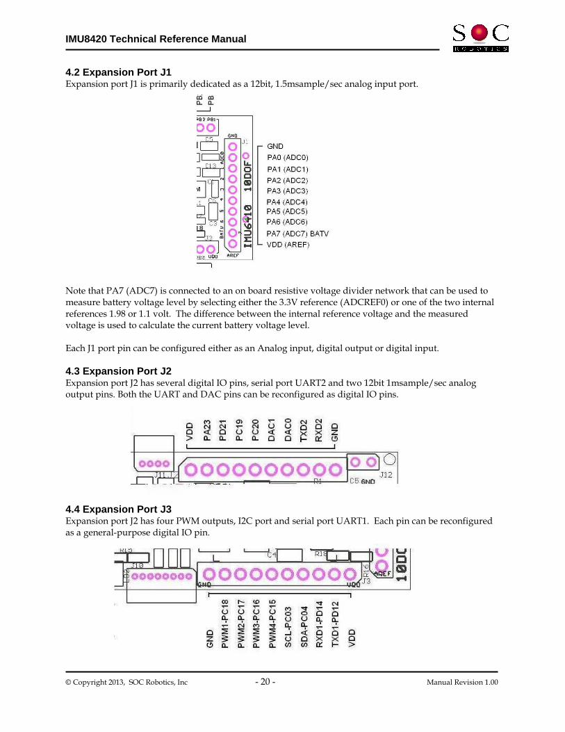
4.2 Expansion Port J1 Expansion port J1 is primarily dedicated as a 12bit, 1.5msample/sec analog input port. Note that PA7 (ADC7) is connected to an on board resistive voltage divider network that can be used to measure battery voltage level by selecting either the 3.3V reference (ADCREF0) or one of the two internal references 1.98 or 1.1 volt. The difference between the internal reference voltage and the measured voltage is used to calculate the current battery voltage level. Each J1 port pin can be configured either as an Analog input, digital output or digital input.
4.3 Expansion Port J2 Expansion port J2 has several digital IO pins, serial port UART2 and two 12bit 1msample/sec analog output pins. Both the UART and DAC pins can be reconfigured as digital IO pins.
4.4 Expansion Port J3 Expansion port J2 has four PWM outputs, I2C port and serial port UART1. Each pin can be reconfigured as a general-purpose digital IO pin.
IMU8420 Technical Reference Manual
© Copyright 2013, SOC Robotics, Inc - 21 - Manual Revision 1.00
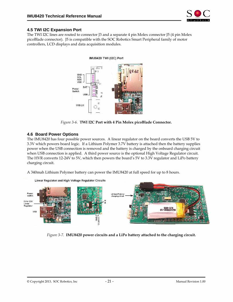
4.5 TWI I2C Expansion Port The TWI I2C lines are routed to connector J3 and a separate 4 pin Molex connector J5 (4 pin Molex picoBlade connector). J5 is compatible with the SOC Robotics Smart Peripheral family of motor controllers, LCD displays and data acquisition modules.
4.6 Board Power Options The IMU8420 has four possible power sources. A linear regulator on the board converts the USB 5V to 3.3V which powers board logic. If a Lithium Polymer 3.7V battery is attached then the battery supplies power when the USB connection is removed and the battery is charged by the onboard charging circuit when USB connection is applied. A third power source is the optional High Voltage Regulator circuit. The HVR converts 12-24V to 5V, which then powers the board’s 5V to 3.3V regulator and LiPo battery charging circuit. A 340mah Lithium Polymer battery can power the IMU8420 at full speed for up to 8 hours.
Figure 3-7. IMU8420 power circuits and a LiPo battery attached to the charging circuit.
Figure 3-6. TWI I2C Port with 4 Pin Molex picoBlade Connector.
IMU8420 Technical Reference Manual
© Copyright 2013, SOC Robotics, Inc - 22 - Manual Revision 1.00
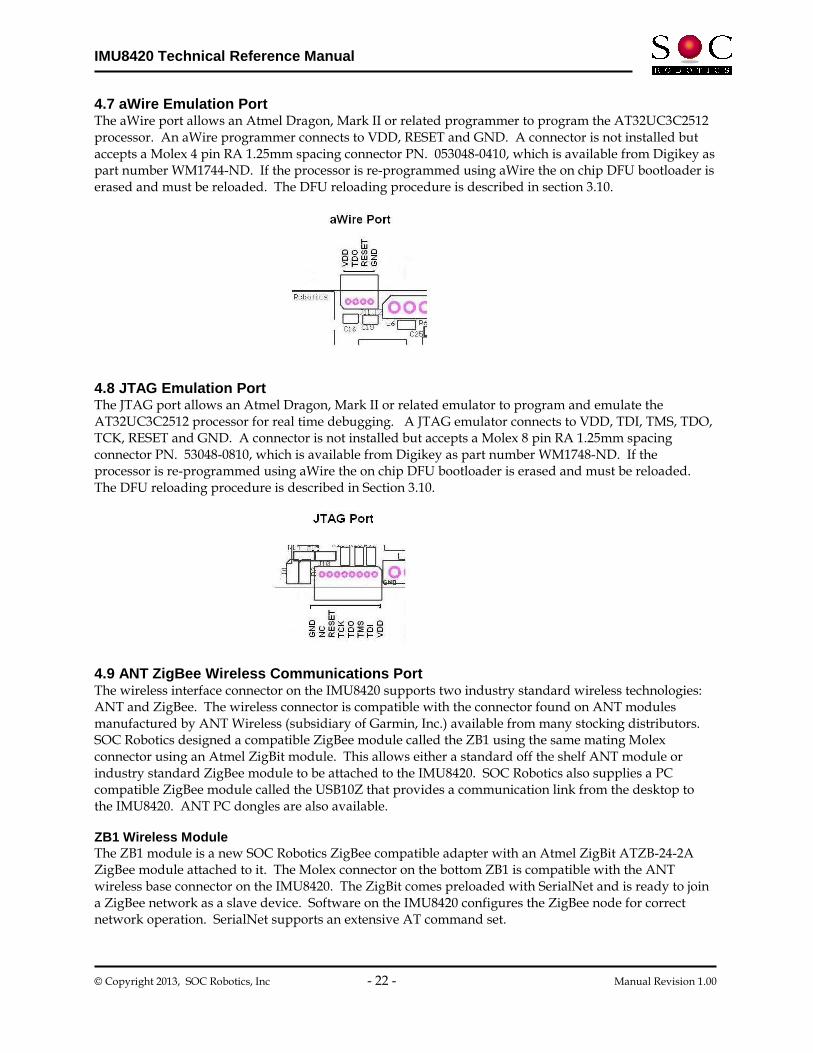
4.7 aWire Emulation Port The aWire port allows an Atmel Dragon, Mark II or related programmer to program the AT32UC3C2512 processor. An aWire programmer connects to VDD, RESET and GND. A connector is not installed but accepts a Molex 4 pin RA 1.25mm spacing connector PN. 053048-0410, which is available from Digikey as part number WM1744-ND. If the processor is re-programmed using aWire the on chip DFU bootloader is erased and must be reloaded. The DFU reloading procedure is described in section 3.10. 4.8 JTAG Emulation Port The JTAG port allows an Atmel Dragon, Mark II or related emulator to program and emulate the AT32UC3C2512 processor for real time debugging. A JTAG emulator connects to VDD, TDI, TMS, TDO, TCK, RESET and GND. A connector is not installed but accepts a Molex 8 pin RA 1.25mm spacing connector PN. 53048-0810, which is available from Digikey as part number WM1748-ND. If the processor is re-programmed using aWire the on chip DFU bootloader is erased and must be reloaded. The DFU reloading procedure is described in Section 3.10. 4.9 ANT ZigBee Wireless Communications Port The wireless interface connector on the IMU8420 supports two industry standard wireless technologies: ANT and ZigBee. The wireless connector is compatible with the connector found on ANT modules manufactured by ANT Wireless (subsidiary of Garmin, Inc.) available from many stocking distributors. SOC Robotics designed a compatible ZigBee module called the ZB1 using the same mating Molex connector using an Atmel ZigBit module. This allows either a standard off the shelf ANT module or industry standard ZigBee module to be attached to the IMU8420. SOC Robotics also supplies a PC compatible ZigBee module called the USB10Z that provides a communication link from the desktop to the IMU8420. ANT PC dongles are also available. ZB1 Wireless Module The ZB1 module is a new SOC Robotics ZigBee compatible adapter with an Atmel ZigBit ATZB-24-2A ZigBee module attached to it. The Molex connector on the bottom ZB1 is compatible with the ANT wireless base connector on the IMU8420. The ZigBit comes preloaded with SerialNet and is ready to join a ZigBee network as a slave device. Software on the IMU8420 configures the ZigBee node for correct network operation. SerialNet supports an extensive AT command set.

IMU8420 Technical Reference Manual
© Copyright 2013, SOC Robotics, Inc - 23 - Manual Revision 1.00
ANT Wireless Modules An ANT wireless module are available from several distributors and is an off the shelf component. Compatible ANT modules are the ANTAP281M5IB and ANTC782M5IB. ANT wireless devices support high speed over air operation with small 8 byte packet data rates reaching 200Hz. IMULINK Java Desktop Application IMULINK is a Windows desktop application written in Java that manages the communication between IMU8420’s and the desktop wirelessly. IMULINK coupled with the next version of the IMU Data Logger software (V1.00 in beta test) allows a user to communicate and control multiple IMU8420’s from the desktop wirelessly. IMULINK synchronizes all IMU clocks, sets log file names on each IMU, starts and stops logging, retrieves min/max readings and retrieves data. USB10Z PC ZigBee The USB10Z is a USB 2.0 to ZigBee communications device that attaches to a PC and is available directly from SOC Robotics, Inc. The USB10Z is based on the USB10 device and runs a small application called the Ferret. The Ferret application creates a serial link between the AT90USB162 processor on the board and the ZigBit module. ZigBit default baud rate is 38,400. A complete summary of the commands supported by the Ferret application is in the USB10 Technical Reference Manual.
IMU8420 Technical Reference Manual
© Copyright 2013, SOC Robotics, Inc - 24 - Manual Revision 1.00
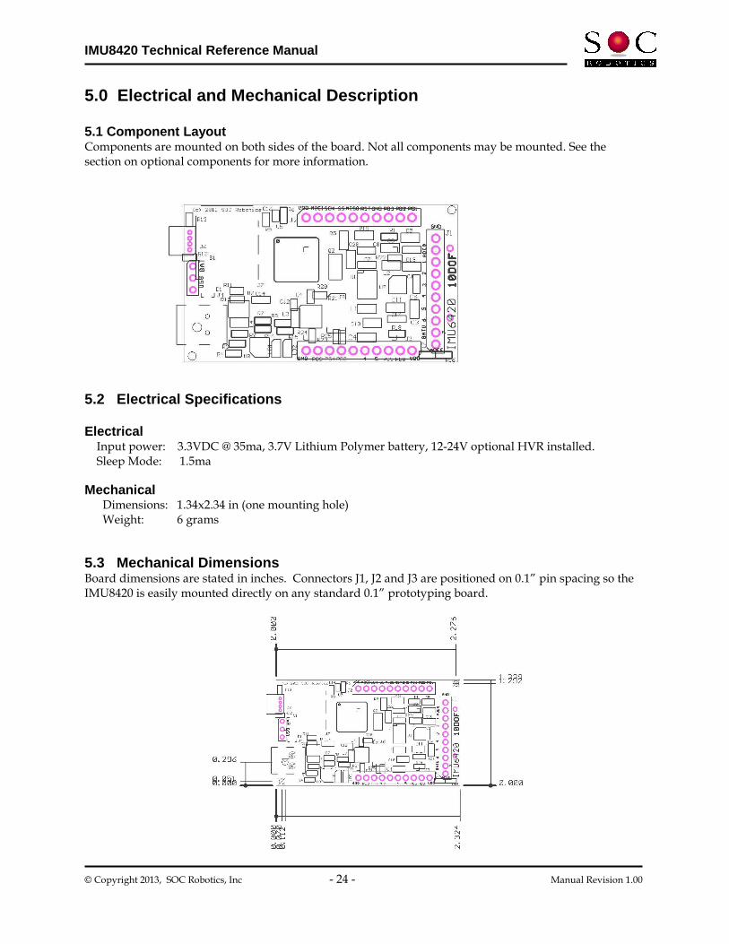
5.0 Electrical and Mechanical Description 5.1 Component Layout Components are mounted on both sides of the board. Not all components may be mounted. See the section on optional components for more information. 5.2 Electrical Specifications Electrical Input power: 3.3VDC @ 35ma, 3.7V Lithium Polymer battery, 12-24V optional HVR installed. Sleep Mode: 1.5ma Mechanical Dimensions: 1.34x2.34 in (one mounting hole) Weight: 6 grams 5.3 Mechanical Dimensions Board dimensions are stated in inches. Connectors J1, J2 and J3 are positioned on 0.1” pin spacing so the IMU8420 is easily mounted directly on any standard 0.1” prototyping board.

IMU8420 Technical Reference Manual
© Copyright 2013, SOC Robotics, Inc - 25 - Manual Revision 1.00
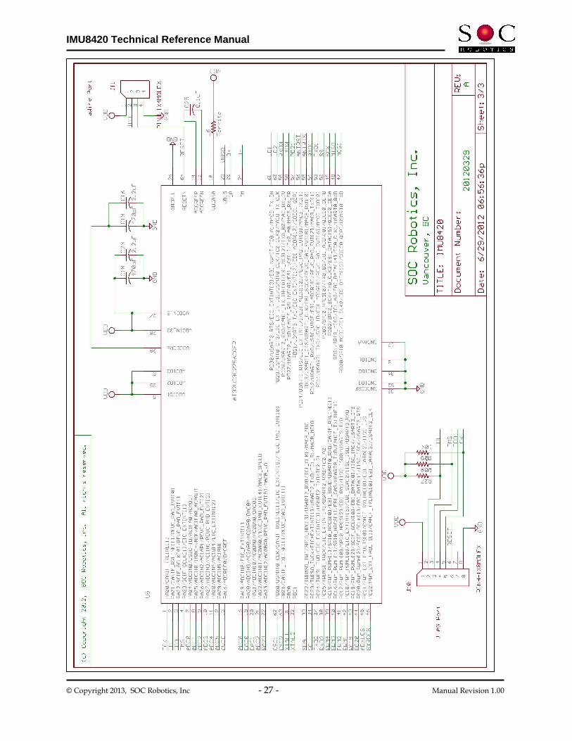
6.0 IMU8420 Rev 1.0 Schematics

IMU8420 Technical Reference Manual
© Copyright 2013, SOC Robotics, Inc - 26 - Manual Revision 1.00
IMU8420 Technical Reference Manual
© Copyright 2013, SOC Robotics, Inc - 27 - Manual Revision 1.00

IMU8420 Technical Reference Manual
© Copyright 2013, SOC Robotics, Inc - 28 - Manual Revision 1.00
Notes: